Groundwater Workshop Well Site Selection, Design, Construction, and Testing Russell Kyle, MS, PG, CHG Wood Rodgers, Inc. American Water Works Association California - Nevada Section Groundwater Workshop, 2015 Rancho Cucamonga, California February 25, 2015
Transcript
Groundwater WorkshopWell Site Selection, Design,
Construction, and Testing
Russell Kyle, MS, PG, CHG
Wood Rodgers, Inc.
American Water Works Association
California-Nevada Section
Groundwater Workshop, 2015
Rancho Cucamonga, California
February 25, 2015
Overview
• Well Site Selection
• Common Well Types
• Well Drilling Methods
• Well Design
• Well Construction
• Well Development
• Aquifer Testing
• Post Construction
Overview
• Well Site Selection
• Common Well Types
• Well Drilling Methods
• Well Design
• Well Construction
• Well Development
• Aquifer Testing
• Post Construction
Well Site Selection
• Define Preliminary Project Objectives
– Capacity requirements
– Specific areas that need water
– Distribution system limitations
– Water quality requirements
– Property availability
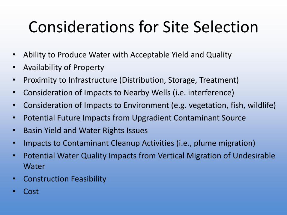
Considerations for Site Selection
• Ability to Produce Water with Acceptable Yield and Quality
• Availability of Property
• Proximity to Infrastructure (Distribution, Storage, Treatment)
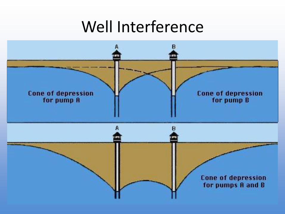
• Consideration of Impacts to Nearby Wells (i.e. interference)
• Consideration of Impacts to Environment (e.g. vegetation, fish, wildlife)
• Potential Future Impacts from Upgradient Contaminant Source
• Basin Yield and Water Rights Issues
• Impacts to Contaminant Cleanup Activities (i.e., plume migration)
• Potential Water Quality Impacts from Vertical Migration of Undesirable Water
• Construction Feasibility
• Cost
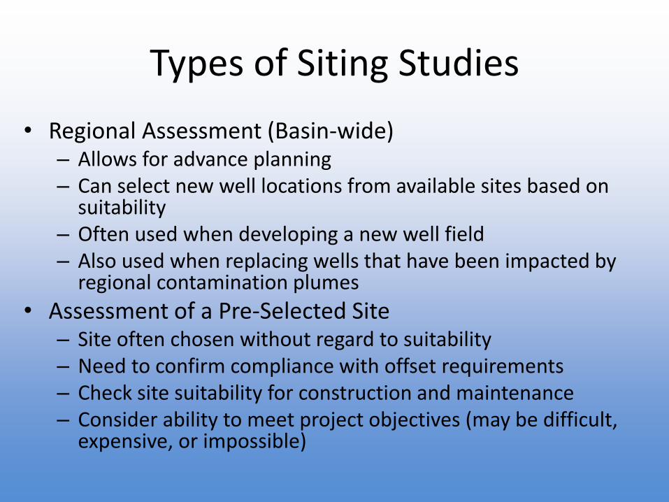
Types of Siting Studies
• Regional Assessment (Basin-wide)– Allows for advance planning– Can select new well locations from available sites based on
suitability– Often used when developing a new well field– Also used when replacing wells that have been impacted by
regional contamination plumes
• Assessment of a Pre-Selected Site– Site often chosen without regard to suitability– Need to confirm compliance with offset requirements– Check site suitability for construction and maintenance – Consider ability to meet project objectives (may be difficult,
expensive, or impossible)
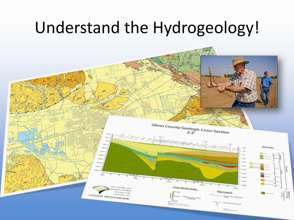
Understand the Hydrogeology!
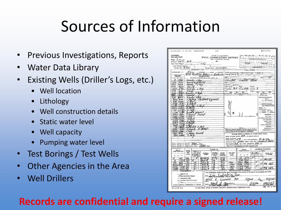
Sources of Information
• Previous Investigations, Reports
• Water Data Library
• Existing Wells (Driller’s Logs, etc.)• Well location
• Lithology
• Well construction details
• Static water level
• Well capacity
• Pumping water level
• Test Borings / Test Wells
• Other Agencies in the Area
• Well Drillers
Records are confidential and require a signed release!
• Water quality data for regulated public systems
• Statewide database available for download
• Typically only includes data submitted for regulatory compliance (purveyors will often have more extensive datasets)
• Does not include any information on well construction or location
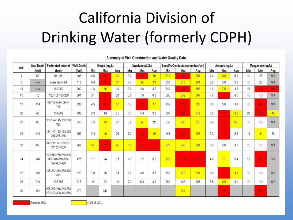
California Division of Drinking Water (formerly CDPH)
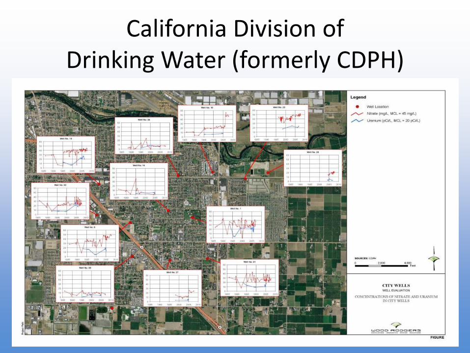
California Division of Drinking Water (formerly CDPH)
California Division of Drinking Water (formerly CDPH)
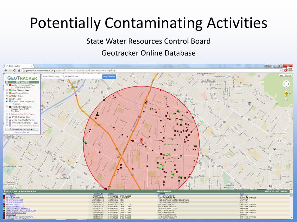
Potentially Contaminating ActivitiesState Water Resources Control Board
Geotracker Online Database
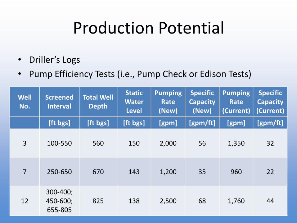
Production Potential
• Driller’s Logs
• Pump Efficiency Tests (i.e., Pump Check or Edison Tests)
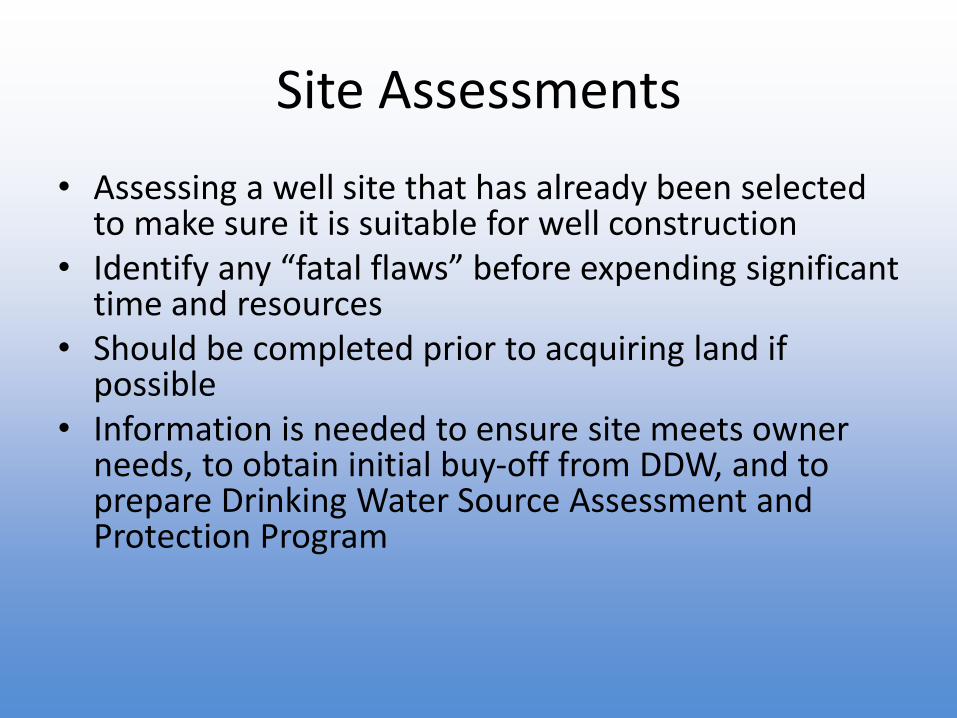
• Assessing a well site that has already been selected to make sure it is suitable for well construction
• Identify any “fatal flaws” before expending significant time and resources
• Should be completed prior to acquiring land if possible
• Information is needed to ensure site meets owner needs, to obtain initial buy-off from DDW, and to prepare Drinking Water Source Assessment and Protection Program
Site Assessments
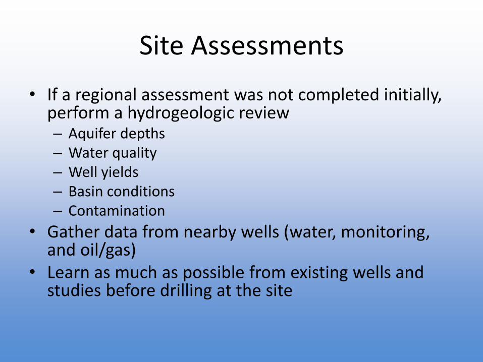
• If a regional assessment was not completed initially, perform a hydrogeologic review– Aquifer depths– Water quality– Well yields– Basin conditions– Contamination
• Gather data from nearby wells (water, monitoring, and oil/gas)
• Learn as much as possible from existing wells and studies before drilling at the site
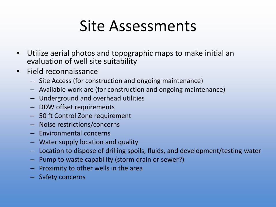
Site Assessments
• Utilize aerial photos and topographic maps to make initial an evaluation of well site suitability
• Field reconnaissance– Site Access (for construction and ongoing maintenance)– Available work are (for construction and ongoing maintenance)– Underground and overhead utilities– DDW offset requirements– 50 ft Control Zone requirement– Noise restrictions/concerns– Environmental concerns– Water supply location and quality– Location to dispose of drilling spoils, fluids, and development/testing water– Pump to waste capability (storm drain or sewer?)– Proximity to other wells in the area– Safety concerns
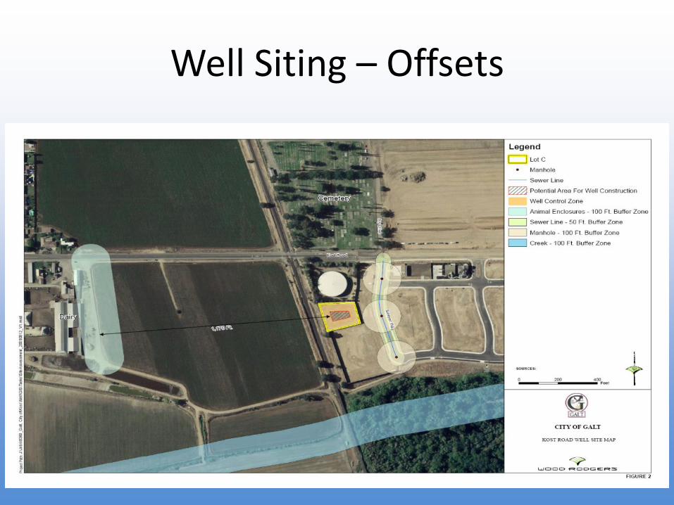
Well Siting – Offsets
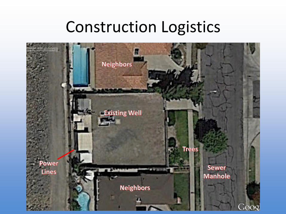
Construction Logistics
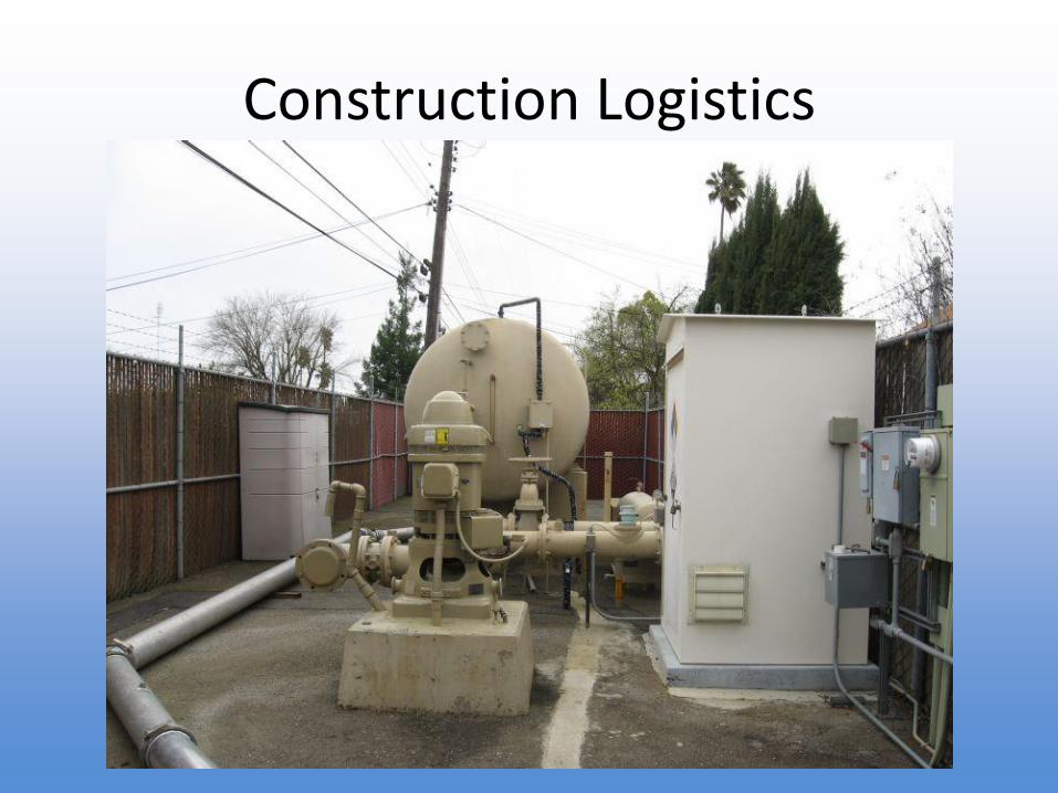
Construction Logistics
Overview
• Well Site Selection
• Common Well Types
• Well Drilling Methods
• Well Design
• Well Construction
• Well Development
• Aquifer Testing
• Post Construction
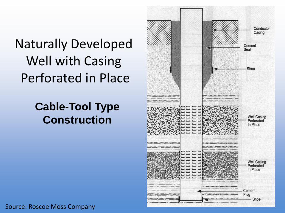
Naturally Developed Well with Casing
Perforated in Place
Cable-Tool Type
Construction
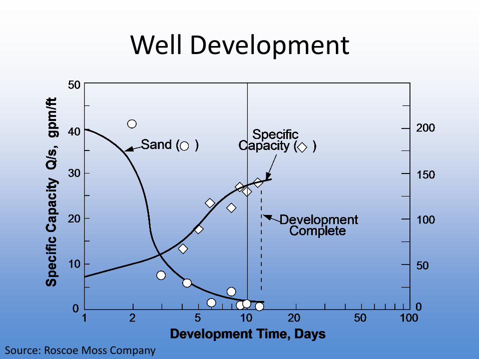
Source: Roscoe Moss Company
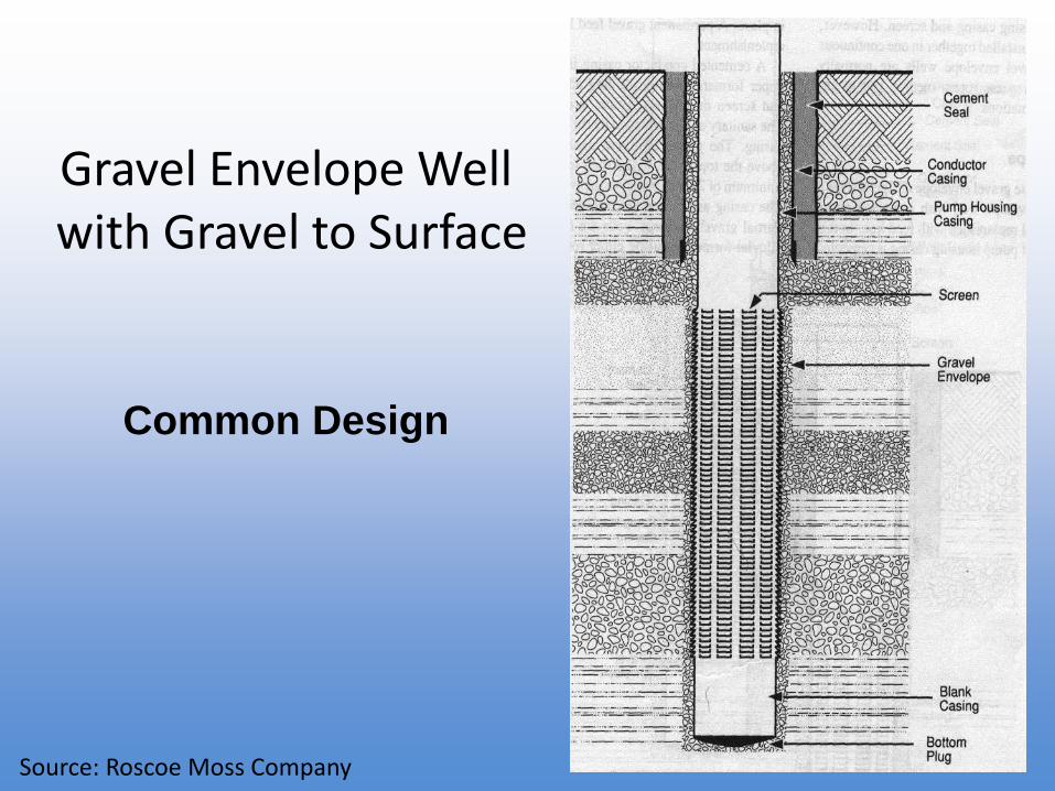
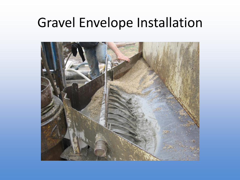
Gravel Envelope Wellwith Gravel to Surface
Common Design
Source: Roscoe Moss Company
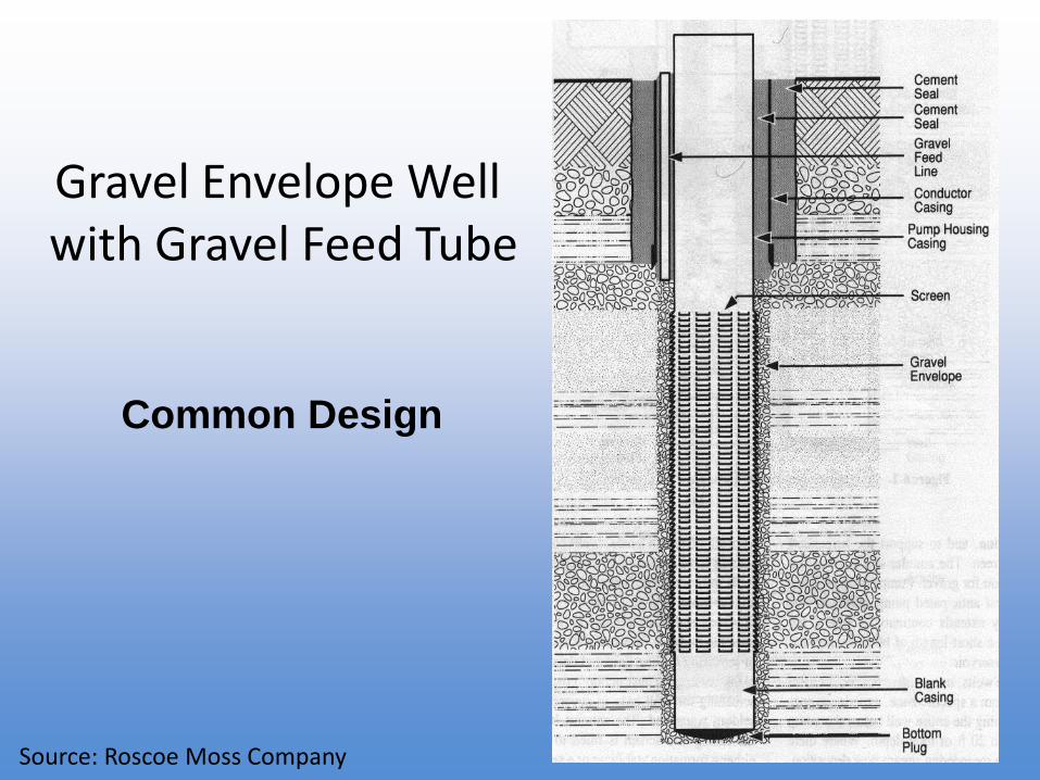
Gravel Envelope Wellwith Gravel Feed Tube
Common Design
Source: Roscoe Moss Company
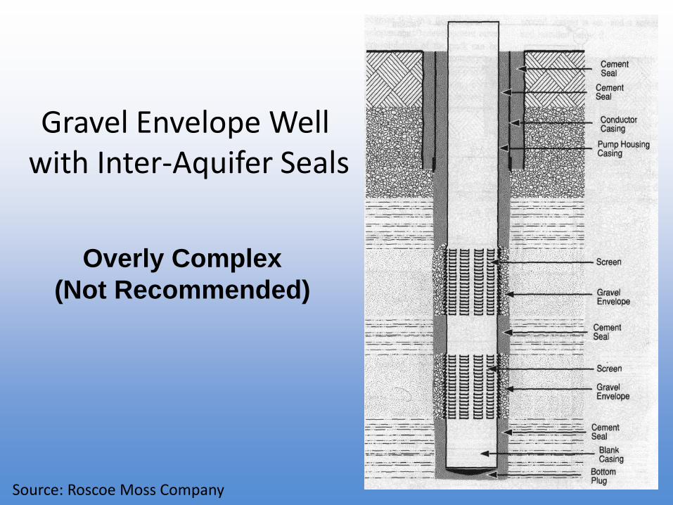
Gravel Envelope Wellwith Inter-Aquifer Seals
Overly Complex
(Not Recommended)
Source: Roscoe Moss Company
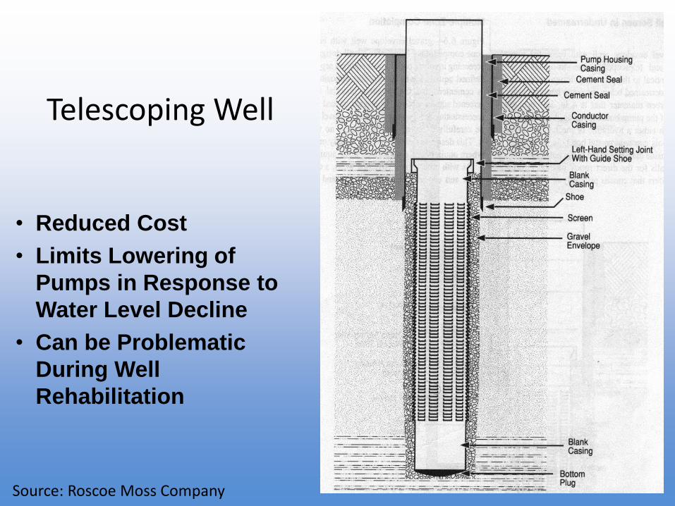
Telescoping Well
• Reduced Cost
• Limits Lowering of
Pumps in Response to
Water Level Decline
• Can be Problematic
During Well
Rehabilitation
Source: Roscoe Moss Company
Overview
• Well Site Selection
• Common Well Types
• Well Drilling Methods
• Well Design
• Well Construction
• Well Development
• Aquifer Testing
• Post Construction
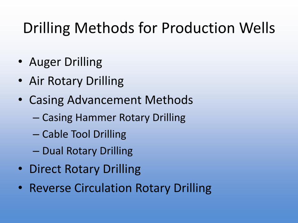
Drilling Methods for Production Wells
• Auger Drilling
• Air Rotary Drilling
• Casing Advancement Methods
– Casing Hammer Rotary Drilling
– Cable Tool Drilling
– Dual Rotary Drilling
• Direct Rotary Drilling
• Reverse Circulation Rotary Drilling
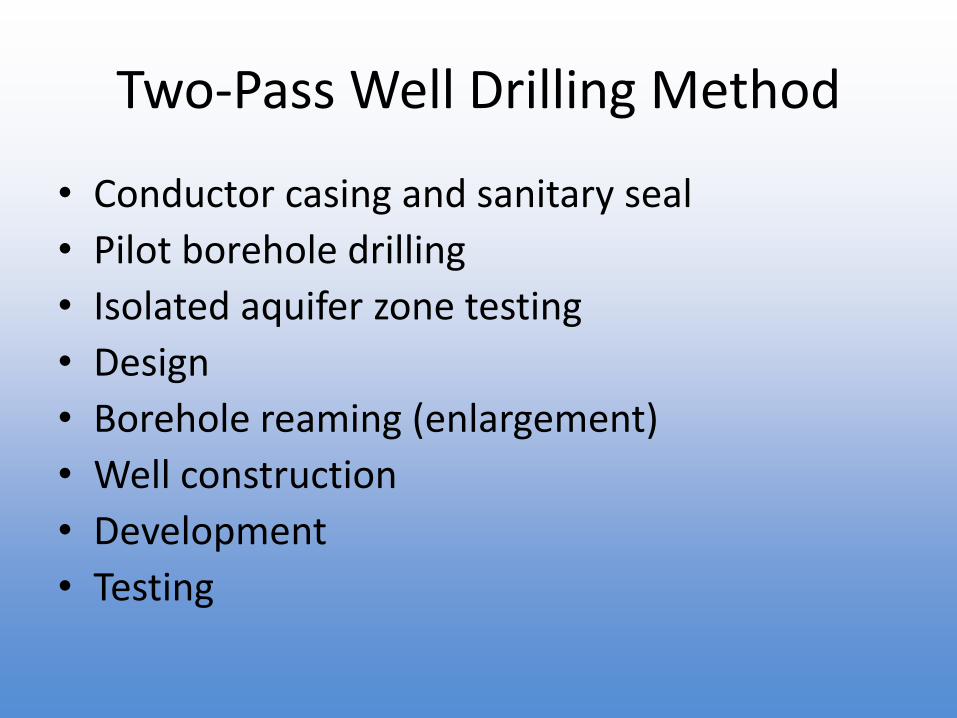
Two-Pass Well Drilling Method
• Conductor casing and sanitary seal
• Pilot borehole drilling
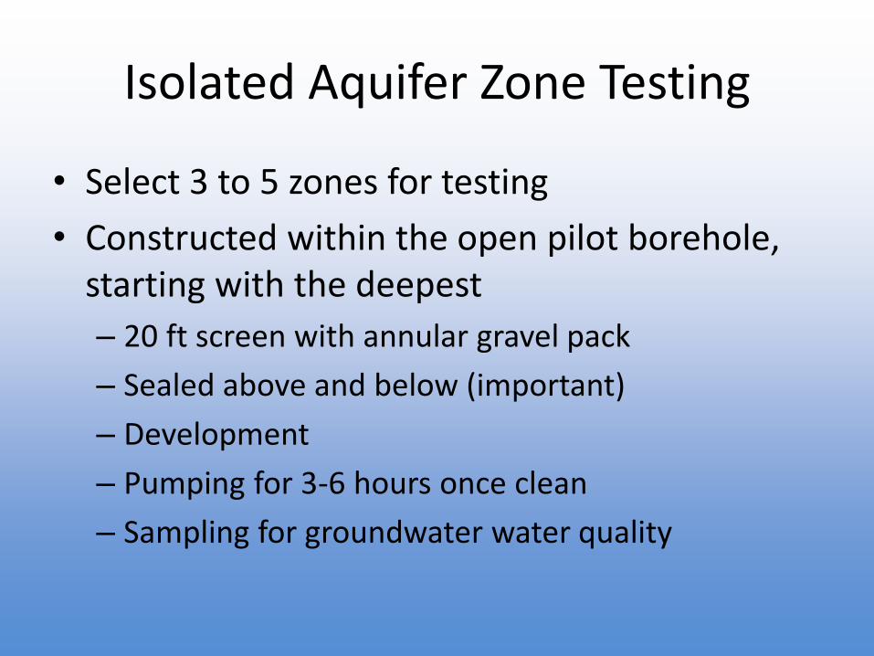
• Isolated aquifer zone testing
• Design
• Borehole reaming (enlargement)
• Well construction
• Development
• Testing
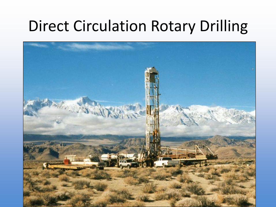
Direct Circulation Rotary Drilling
Direct Circulation
Rotary Drilling
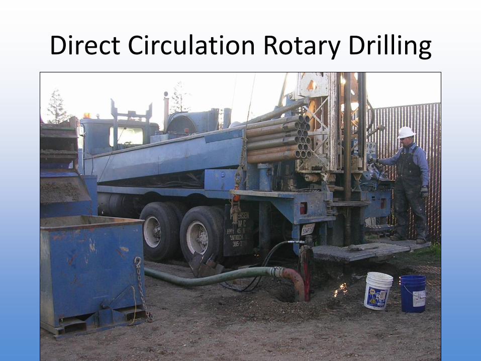
Direct Circulation Rotary Drilling
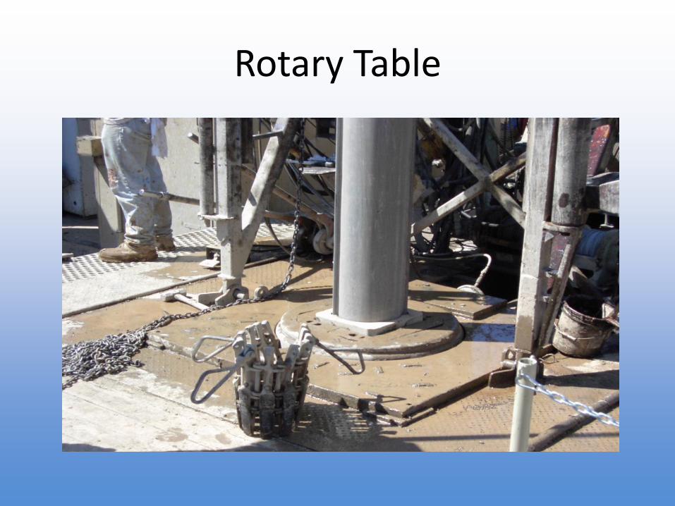
Rotary Table
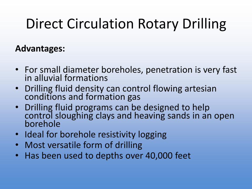
Direct Circulation Rotary Drilling
Advantages:
• For small diameter boreholes, penetration is very fast in alluvial formations
• Drilling fluid density can control flowing artesian conditions and formation gas
• Drilling fluid programs can be designed to help control sloughing clays and heaving sands in an open borehole
• Ideal for borehole resistivity logging• Most versatile form of drilling• Has been used to depths over 40,000 feet
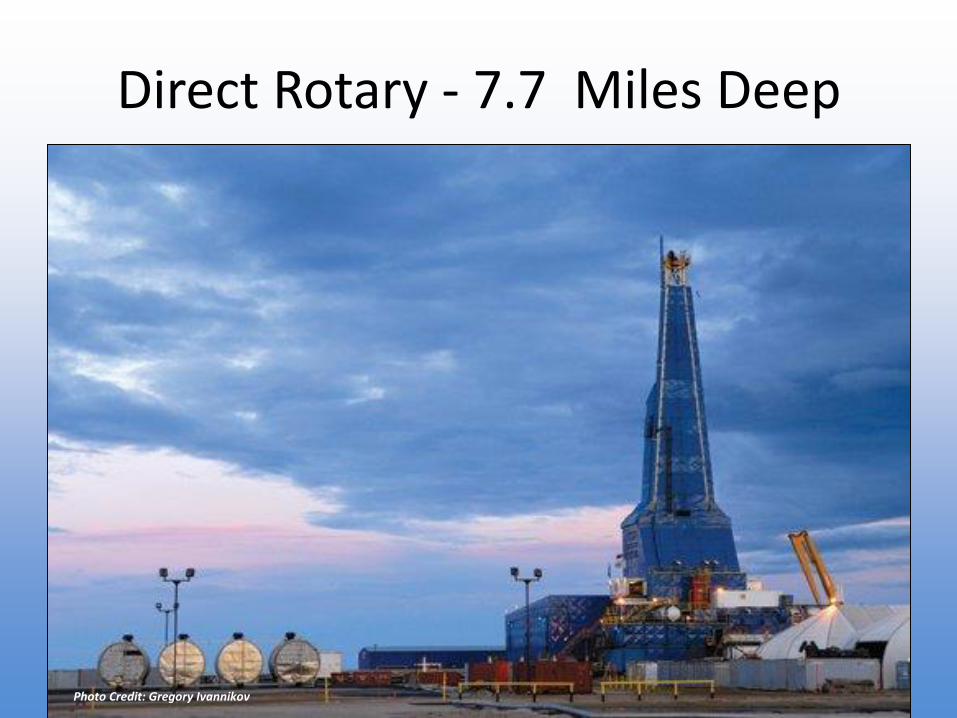
Direct Rotary - 7.7 Miles Deep
Photo Credit: Gregory Ivannikov
Direct Circulation Rotary Drilling
Disadvantages:
• Requires potable water for drilling fluid makeup• Requires mud mixing equipment and drilling fluid
circulation system• Large diameter boreholes require high viscosity drilling
fluids to remove the formation cuttings• Drilling fluid additives may cause aquifer damage• Drilling fluid can be expensive to dispose of in urban
settings• Higher downhole fluid velocities can lead to borehole
washouts
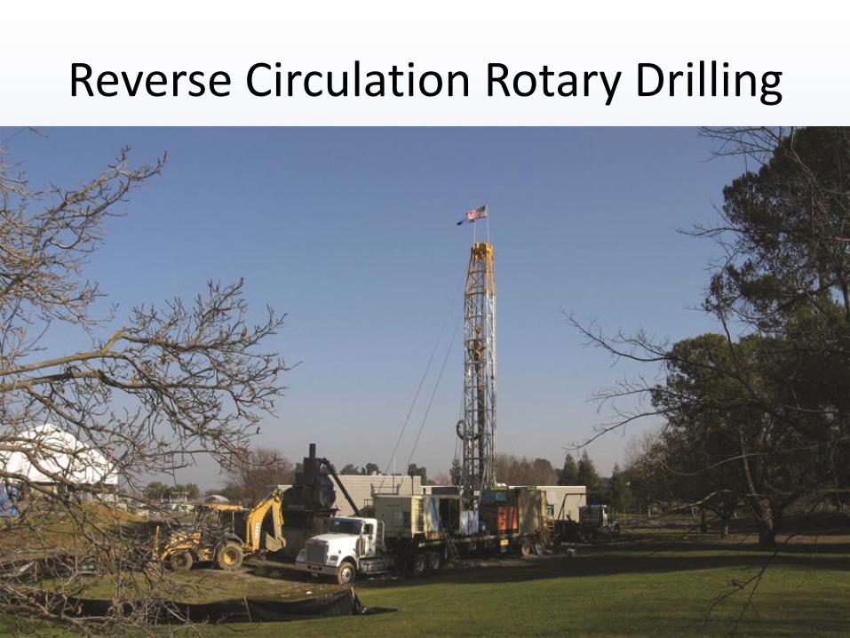
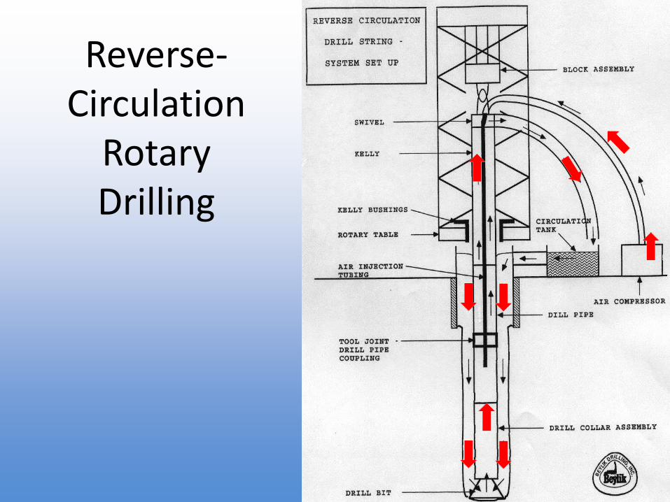
Reverse Circulation Rotary Drilling
Reverse-Circulation
Rotary Drilling
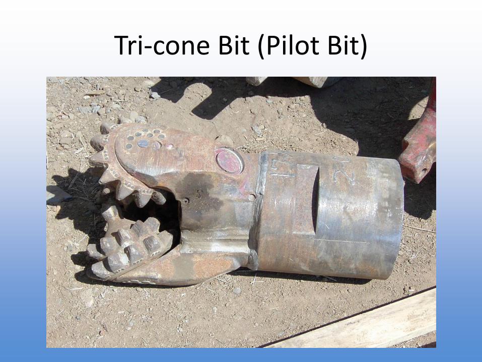
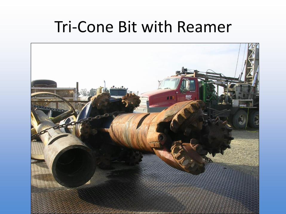
Tri-cone Bit (Pilot Bit)
Tri-Cone Bit with Reamer
Weight Indicators
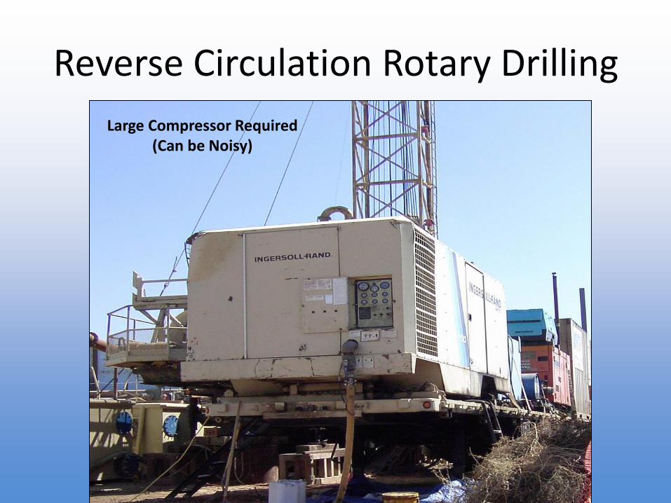
Reverse Circulation Rotary Drilling
Large Compressor Required(Can be Noisy)
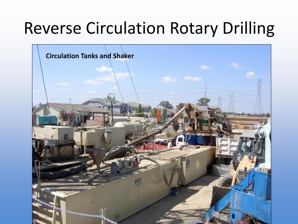
Reverse Circulation Rotary Drilling
Circulation Tanks and Shaker
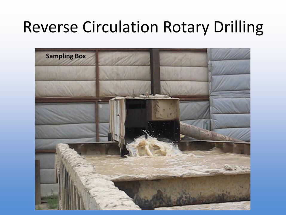
Reverse Circulation Rotary Drilling
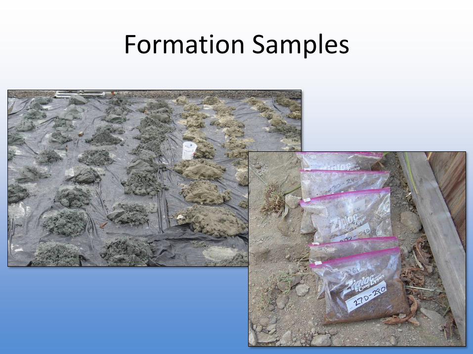
Sampling Box
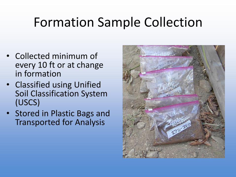
Formation Samples
Reverse Circulation Rotary Drilling
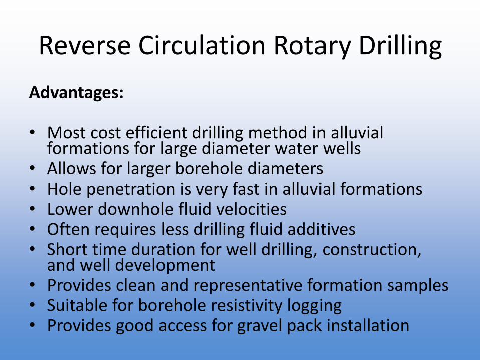
Advantages:
• Most cost efficient drilling method in alluvial formations for large diameter water wells
• Allows for larger borehole diameters• Hole penetration is very fast in alluvial formations• Lower downhole fluid velocities• Often requires less drilling fluid additives • Short time duration for well drilling, construction,
and well development • Provides clean and representative formation samples• Suitable for borehole resistivity logging • Provides good access for gravel pack installation
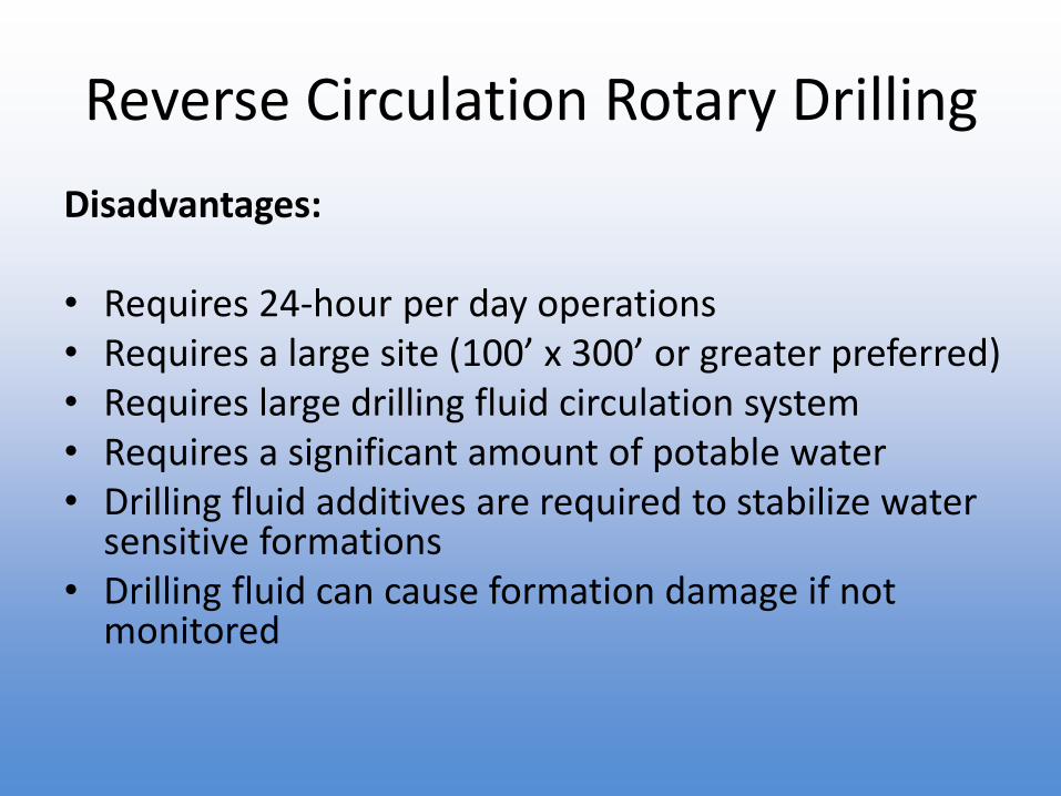
Reverse Circulation Rotary Drilling
Disadvantages:
• Requires 24-hour per day operations• Requires a large site (100’ x 300’ or greater preferred)• Requires large drilling fluid circulation system• Requires a significant amount of potable water• Drilling fluid additives are required to stabilize water
sensitive formations• Drilling fluid can cause formation damage if not
monitored
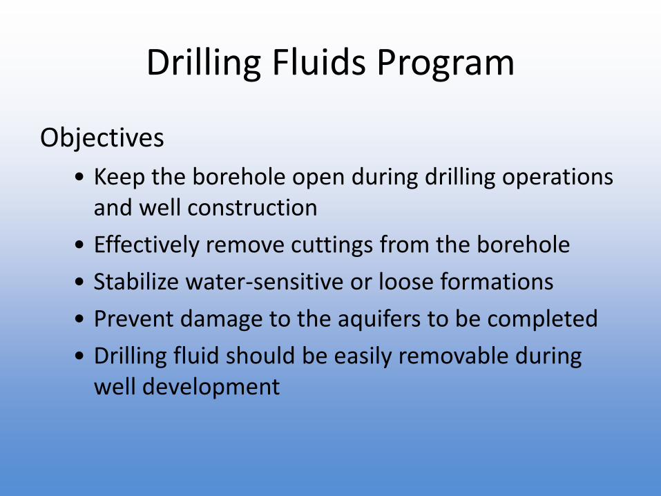
Drilling Fluids Program
Objectives
• Keep the borehole open during drilling operations and well construction
• Effectively remove cuttings from the borehole
• Stabilize water-sensitive or loose formations
• Prevent damage to the aquifers to be completed
• Drilling fluid should be easily removable during well development
Drilling Methods Summary
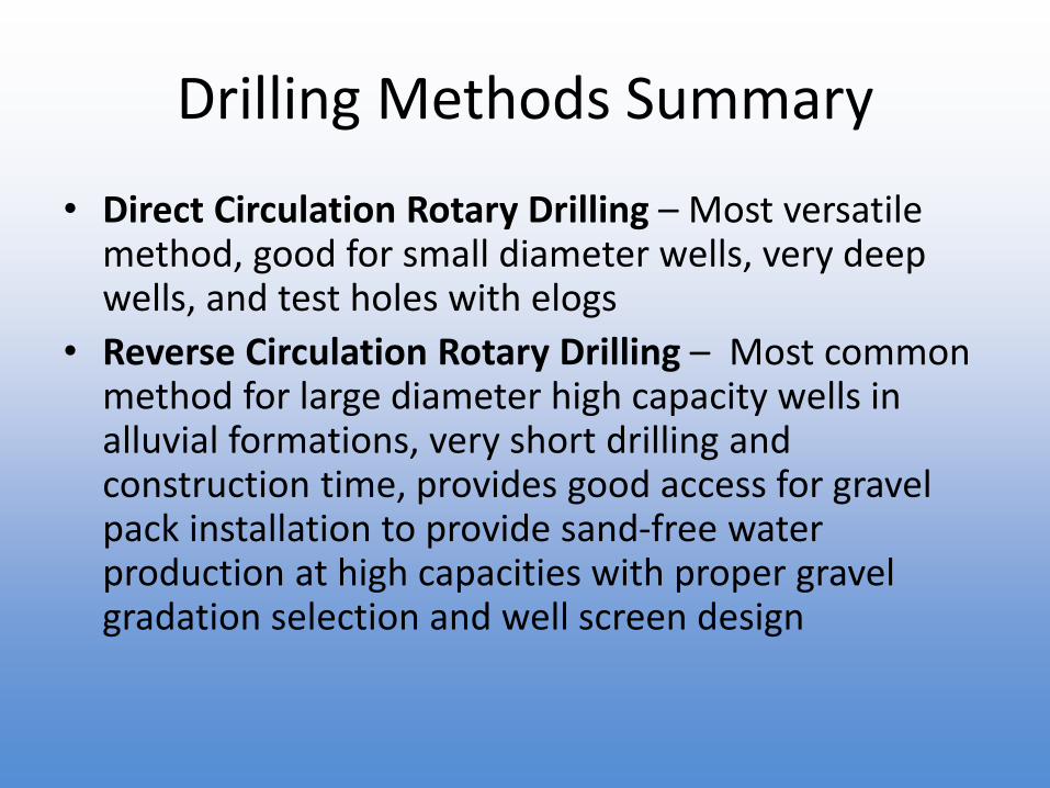
• Direct Circulation Rotary Drilling – Most versatile method, good for small diameter wells, very deep wells, and test holes with elogs
• Reverse Circulation Rotary Drilling – Most common method for large diameter high capacity wells in alluvial formations, very short drilling and construction time, provides good access for gravel pack installation to provide sand-free water production at high capacities with proper gravel gradation selection and well screen design
Overview
• Well Site Selection
• Common Well Types
• Well Drilling Methods
• Well Design
• Well Construction
• Well Development
• Aquifer Testing
• Post Construction
Design Objectives
• Desired Water Quality
• Total Capacity Needed
• Desired Well Efficiency
• Operational Plans
• Desired Well Service Life
• Sand Production Requirements
• Budget
• Schedule
Well Design Requirements and Standards
• Local Agency Well Standards
• California Department of Water Resources (DWR) Bulletin 74-90 Well Standards
• California Department of Drinking Water (DDW) Requirements
• AWWA Standard for Water Wells A 100
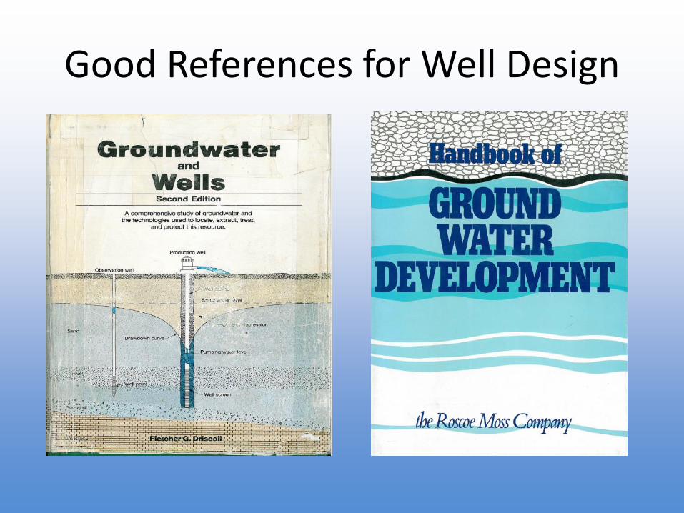
Good References for Well Design
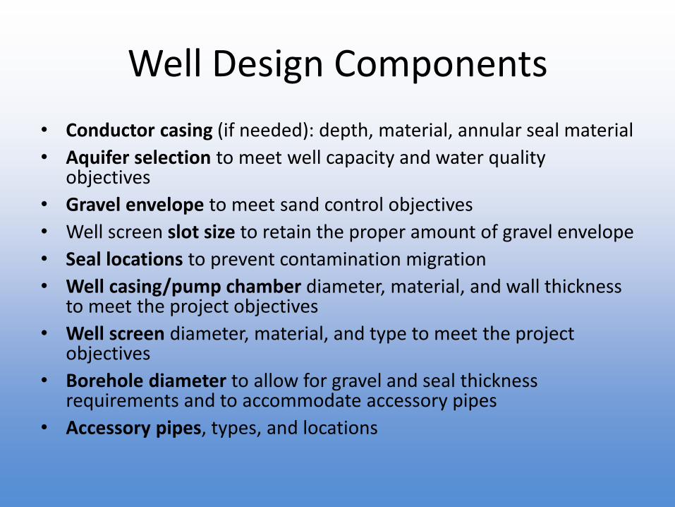
Well Design Components
• Conductor casing (if needed): depth, material, annular seal material
• Aquifer selection to meet well capacity and water quality objectives
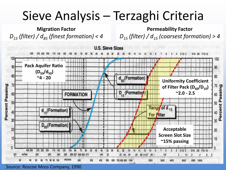
• Gravel envelope to meet sand control objectives
• Well screen slot size to retain the proper amount of gravel envelope
• Seal locations to prevent contamination migration
• Well casing/pump chamber diameter, material, and wall thickness to meet the project objectives
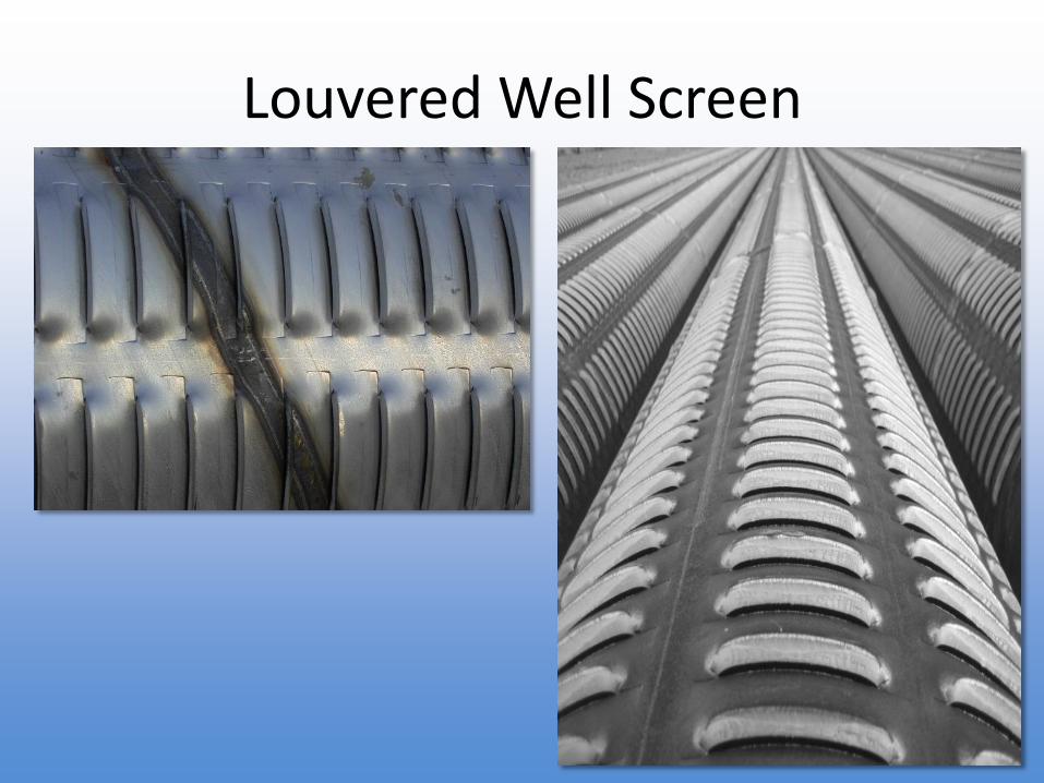
• Well screen diameter, material, and type to meet the project objectives
• Borehole diameter to allow for gravel and seal thickness requirements and to accommodate accessory pipes
• Accessory pipes, types, and locations
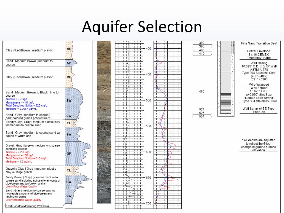
Aquifer Criteria
• Acceptable water quality (from zone testing)
• Sufficient yield
• Separation from contamination
• Confining zones above to seal against
Aquifer Selection
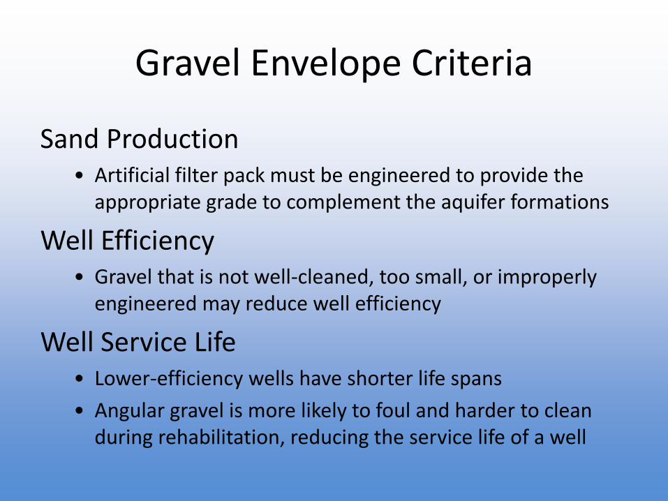
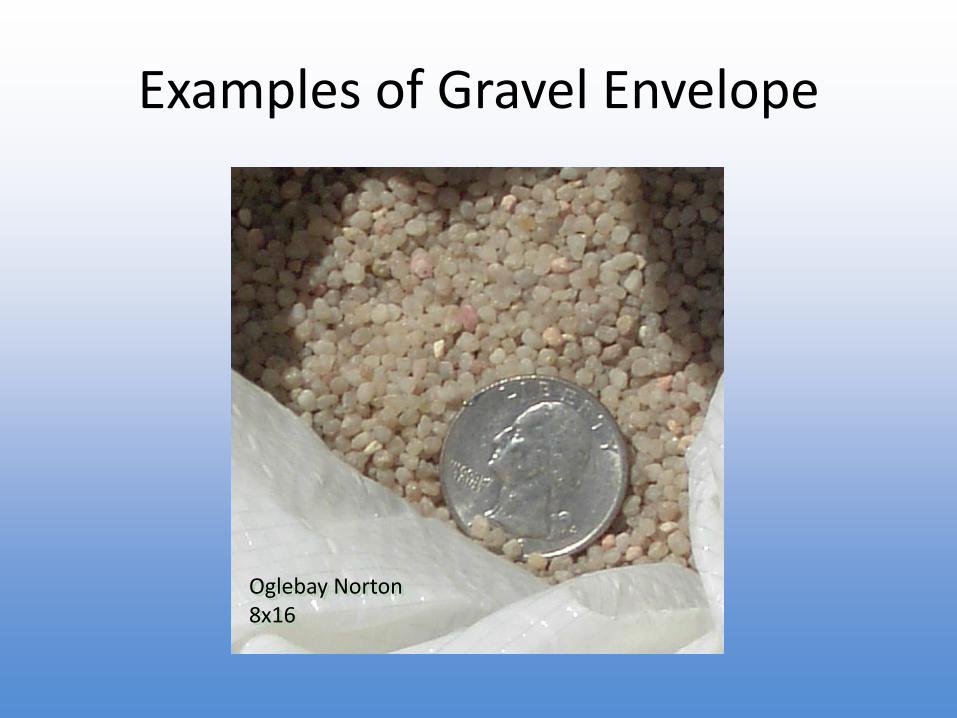
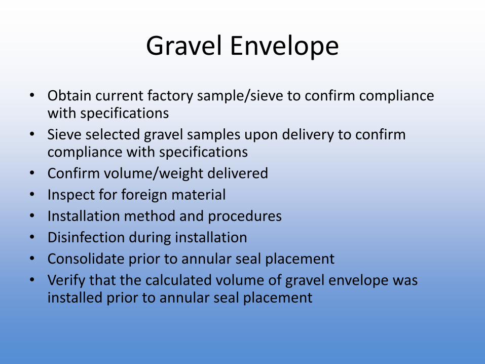
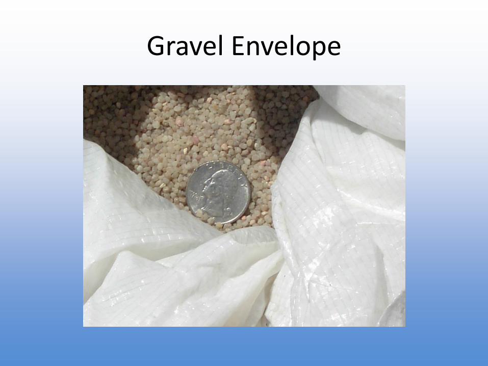
Gravel Envelope Criteria
Sand Production• Artificial filter pack must be engineered to provide the
appropriate grade to complement the aquifer formations
Well Efficiency• Gravel that is not well-cleaned, too small, or improperly
engineered may reduce well efficiency
Well Service Life• Lower-efficiency wells have shorter life spans
• Angular gravel is more likely to foul and harder to clean during rehabilitation, reducing the service life of a well
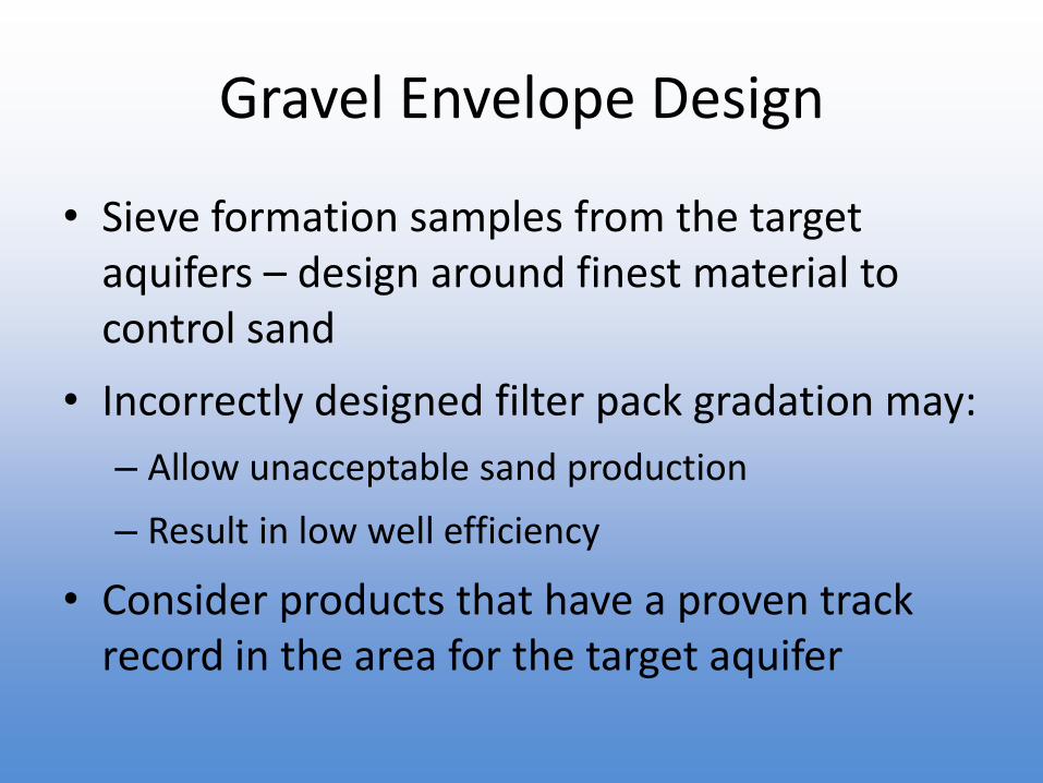
Gravel Envelope Design
• Sieve formation samples from the target aquifers – design around finest material to control sand
• Incorrectly designed filter pack gradation may:
– Allow unacceptable sand production
– Result in low well efficiency
• Consider products that have a proven track record in the area for the target aquifer
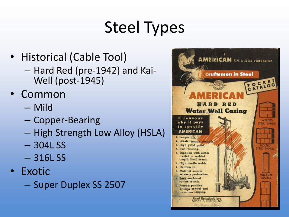
• Historical (Cable Tool)– Hard Red (pre-1942) and Kai-
Well (post-1945)
• Common– Mild– Copper-Bearing– High Strength Low Alloy (HSLA)– 304L SS– 316L SS
• Exotic– Super Duplex SS 2507
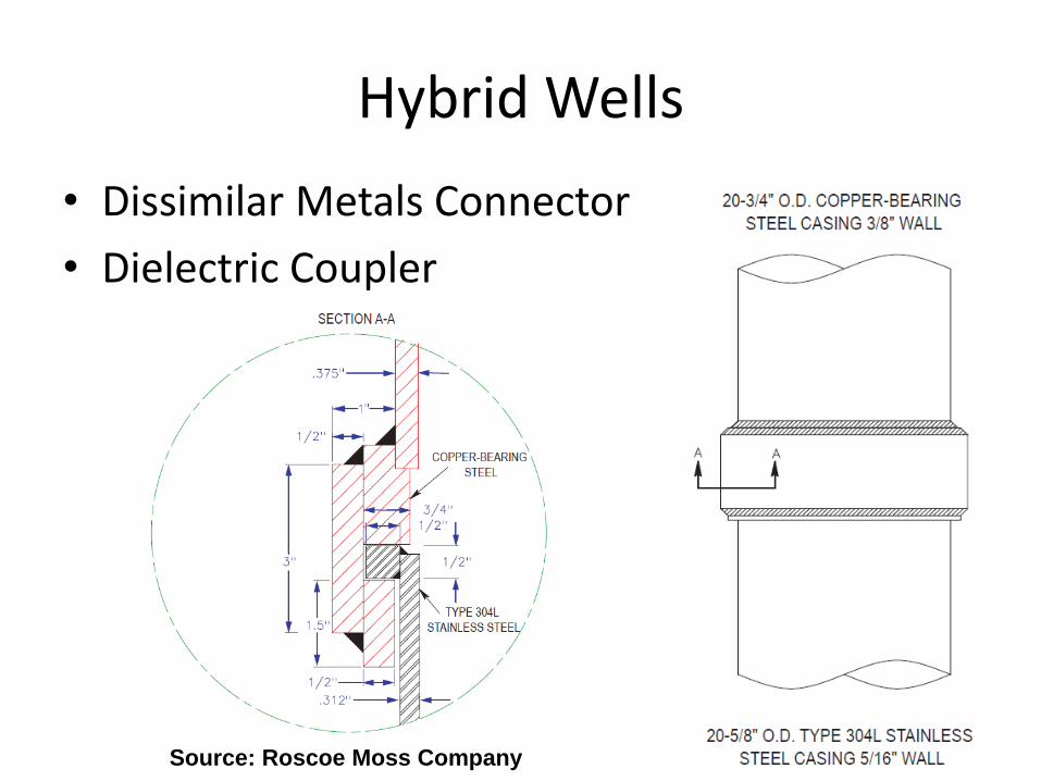
Hybrid Wells
• Dissimilar Metals Connector
• Dielectric Coupler
Source: Roscoe Moss Company
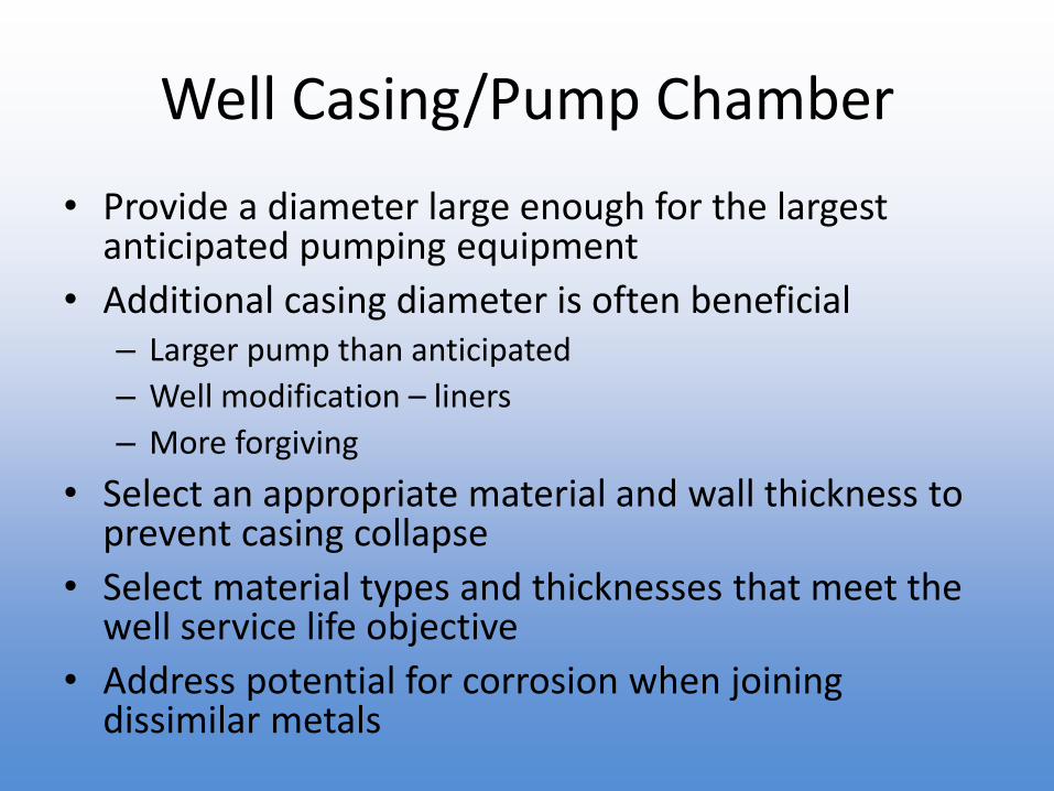
Well Casing/Pump Chamber
• Provide a diameter large enough for the largest anticipated pumping equipment
• Additional casing diameter is often beneficial– Larger pump than anticipated
– Well modification – liners
– More forgiving
• Select an appropriate material and wall thickness to prevent casing collapse
• Select material types and thicknesses that meet the well service life objective
• Address potential for corrosion when joining dissimilar metals
Well Casing/Pump Chamber
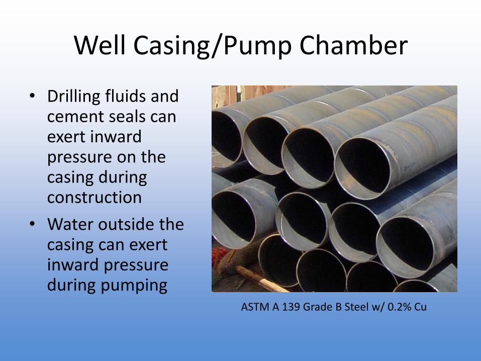
• Drilling fluids and cement seals can exert inward pressure on the casing during construction
• Water outside the casing can exert inward pressure during pumping
ASTM A 139 Grade B Steel w/ 0.2% Cu
Well Casing/Pump Chamber
Other well casing design considerations:
• Calculate the collapse pressure for each casing type to confirm the materials can withstand pressures exerted during well construction and pumping operations of the completed well
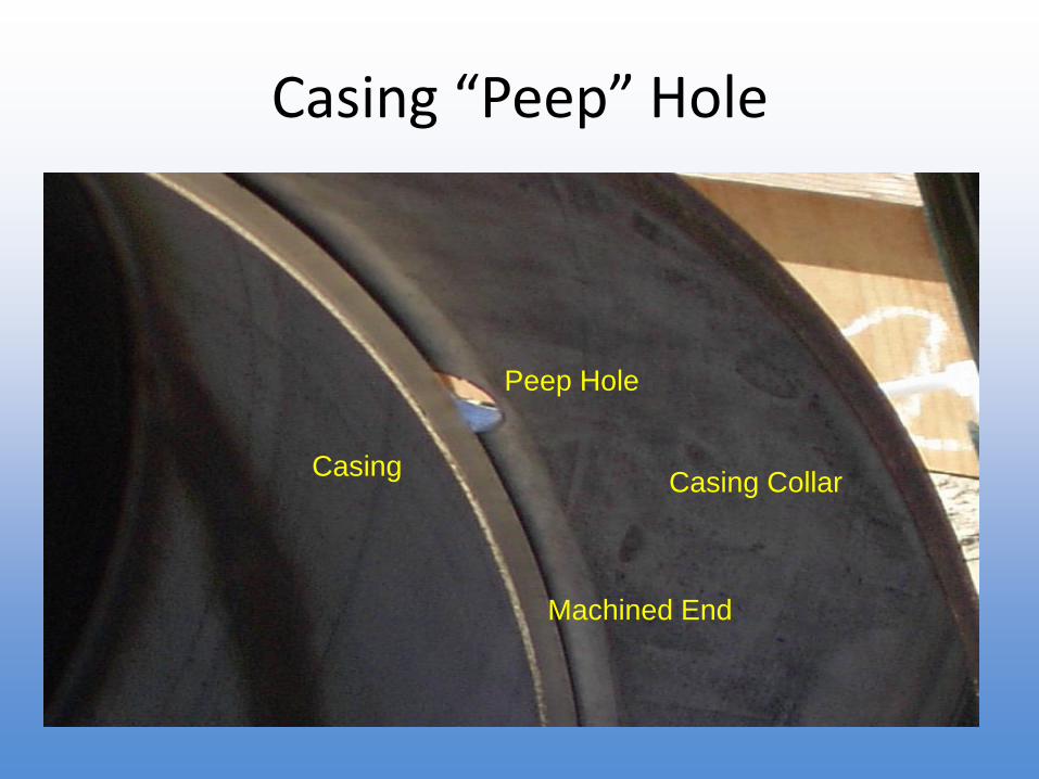
• Adding sounding and camera ports will significantly weaken the casing
• Pumping cement seals applies additional pressure to the casing
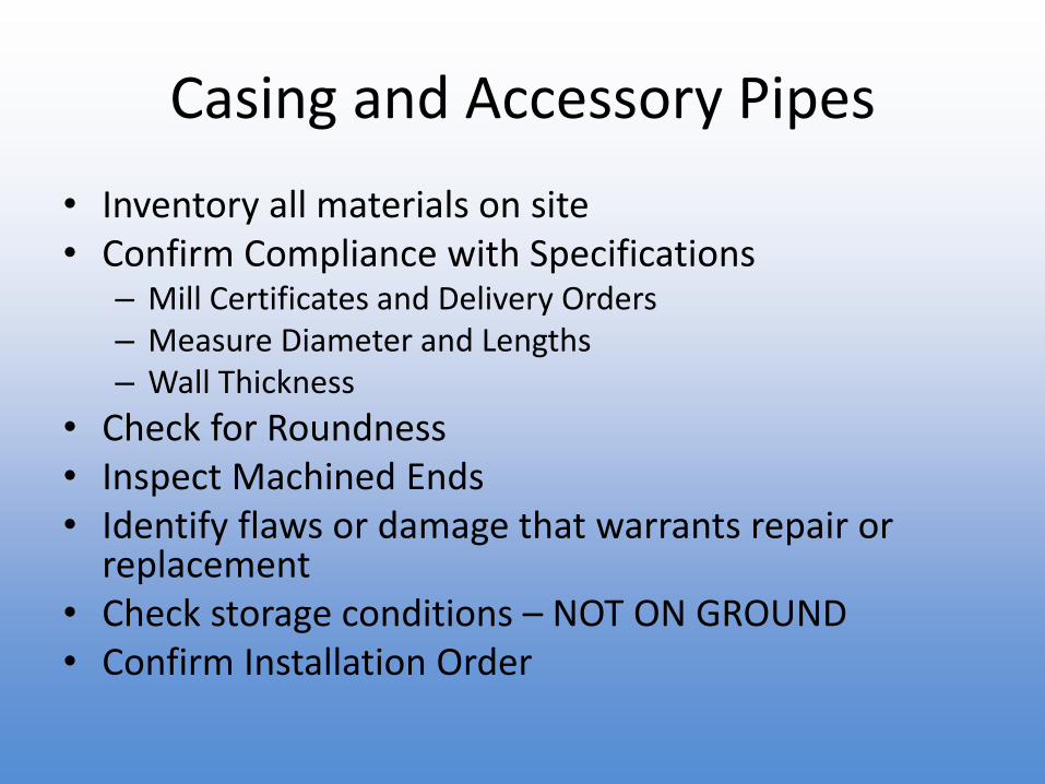
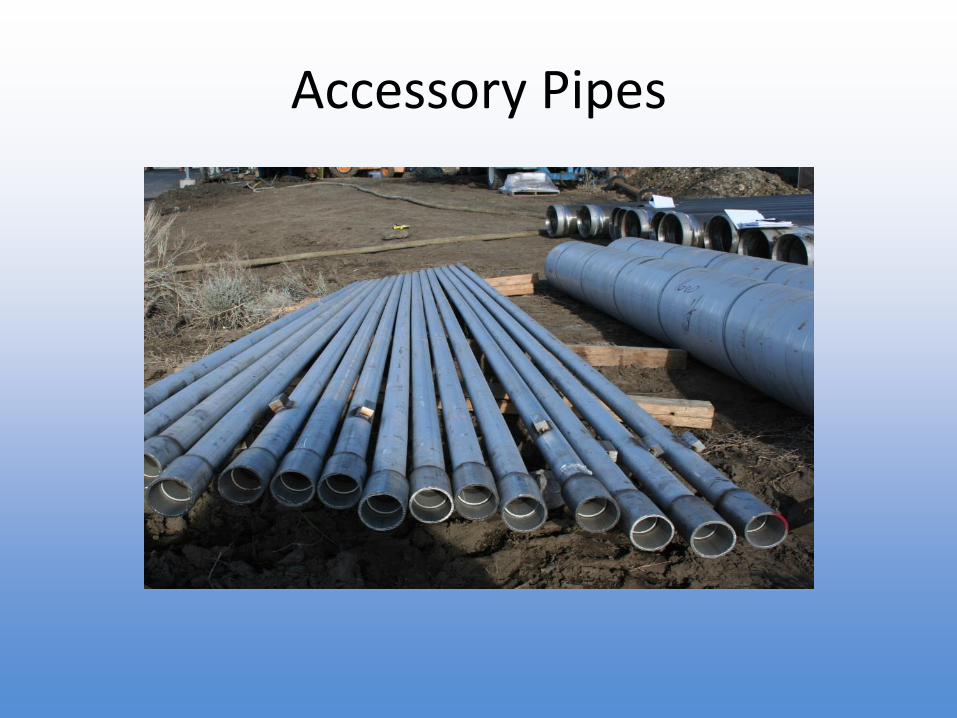
Accessory Pipes
• Provide adequate internal diameter for the intended use
• Select materials and wall thickness to meet the well service life objective
• Provide adequate borehole diameter to ensure seals can be placed around the pipes (2-inch annulus)
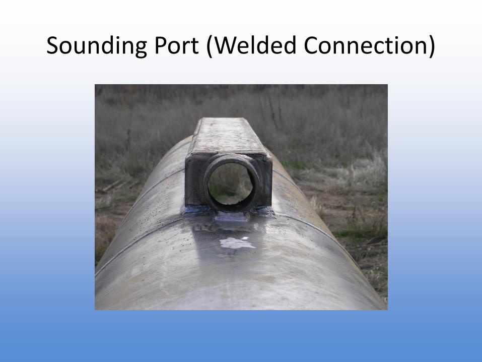
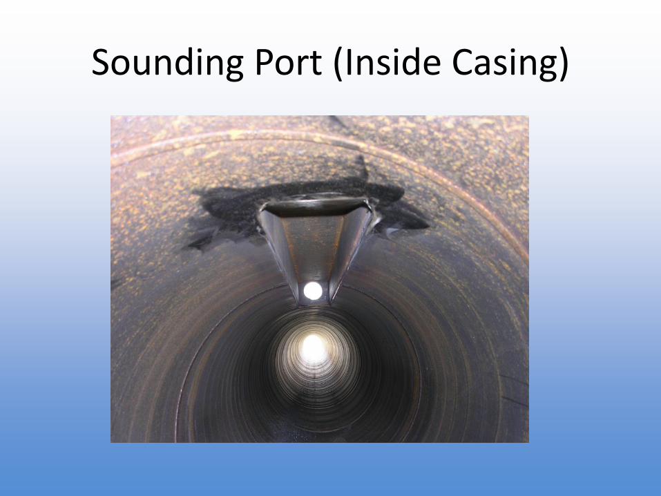
• Injection, camera, and sounding ports should have smooth entrances to the well casing
• Inlet depths should be designed for planned uses
• Weld all accessory pipe joints
Example Accessory Pipes
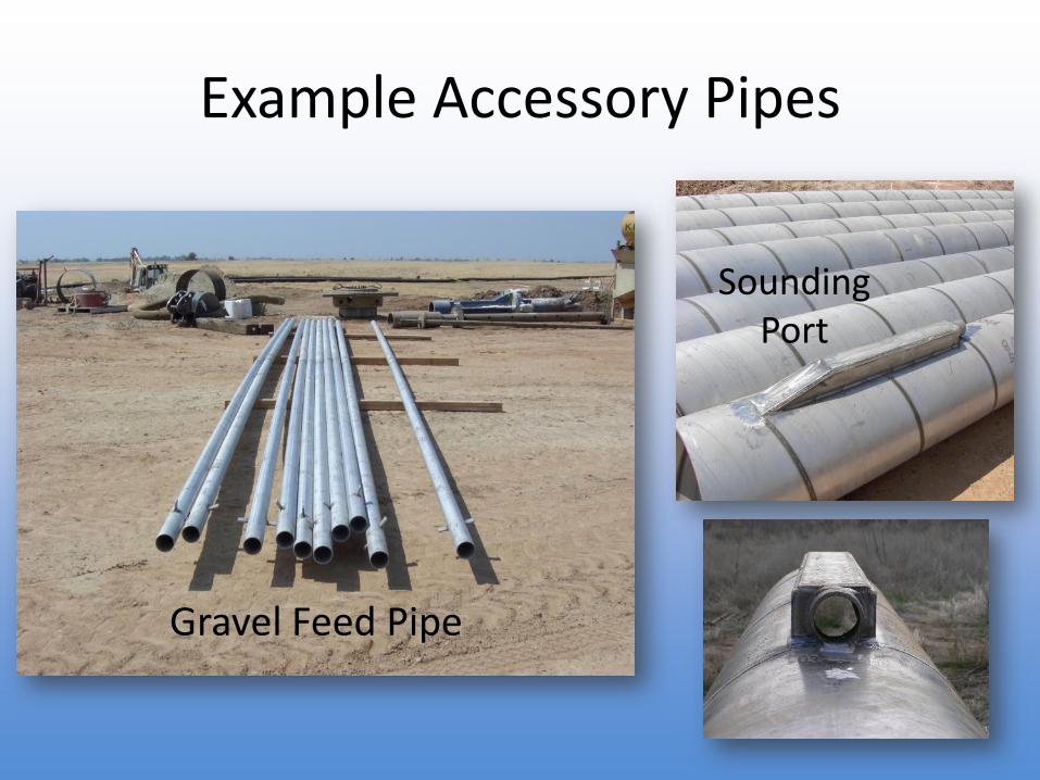
Gravel Feed Pipe
SoundingPort
Conductor Casing
• Often fulfills “sanitary” seal requirements with DDW
• Stabilizes surface materials to allow circulation of fluids during drilling
• May aid in sealing very permeable unsaturated (dry) formations that could cause lost circulation
• Typically mild steel casing, normally sealed with cement grout that is pumped under pressure
• The production borehole is drilled through the conductor casing, so it must be plumb
• Large enough to allow for largest anticipated reamed borehole diameter
Annular Seals
“Sanitary” Seals• Regulatory term for a surface seal with specified minimum
requirements
• Minimum requirements may not meet project objectives
Surface Seals• Seal off upper aquifers
• Provide a barrier against the downward migration of contamination
Intermediate Seals• Isolate aquifers
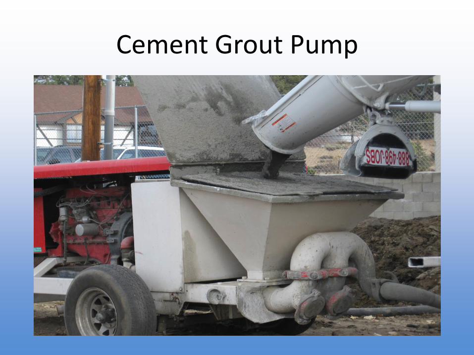
Sand/Cement Grout
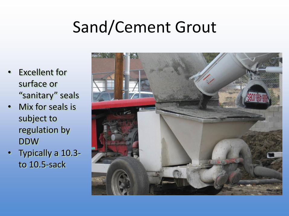
• Excellent for surface or “sanitary” seals
• Mix for seals is subject to regulation by DDW
• Typically a 10.3-to 10.5-sack
Well Design Summary
• The additional material costs for an extended well life are relatively small portion of the cost of a new well and pump station
• Viable new well sites are going to continue to become harder to locate and more expensive to purchase
• Not every well can be designed with a 100-year service life; however, advanced design considerations can extend the life of a well in most settings
Overview
• Well Site Selection
• Common Well Types
• Well Drilling Methods
• Well Design
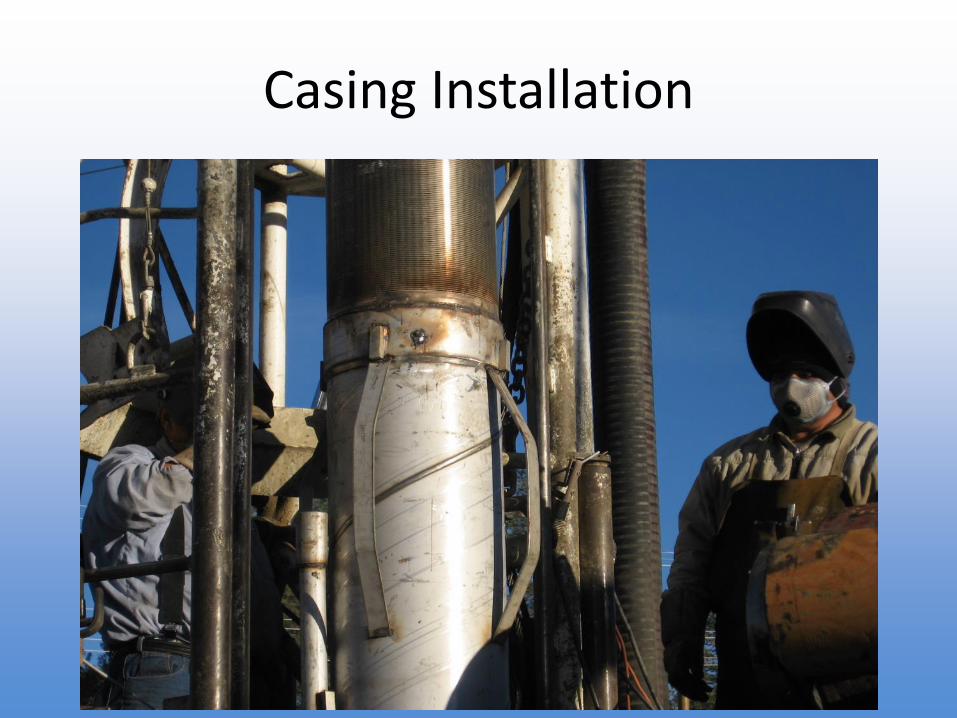
• Well Construction
• Well Development
• Aquifer Testing
• Post Construction
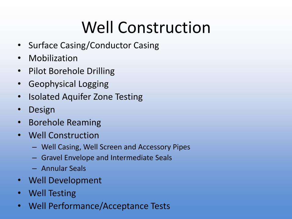
Well Construction• Surface Casing/Conductor Casing
• Mobilization
• Pilot Borehole Drilling
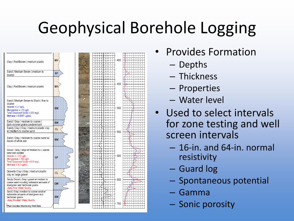
• Geophysical Logging
• Isolated Aquifer Zone Testing
• Design
• Borehole Reaming
• Well Construction– Well Casing, Well Screen and Accessory Pipes
– Gravel Envelope and Intermediate Seals
– Annular Seals
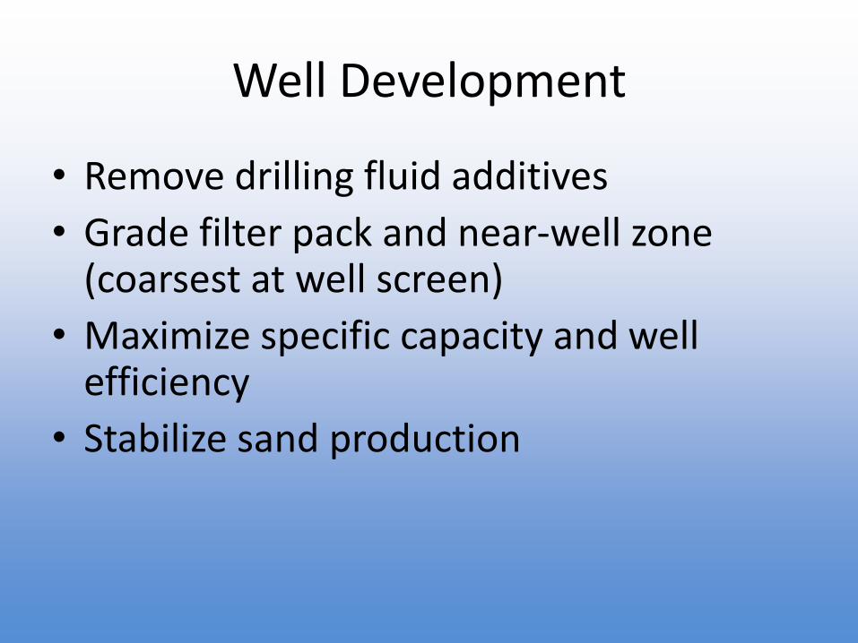
• Well Development
• Well Testing
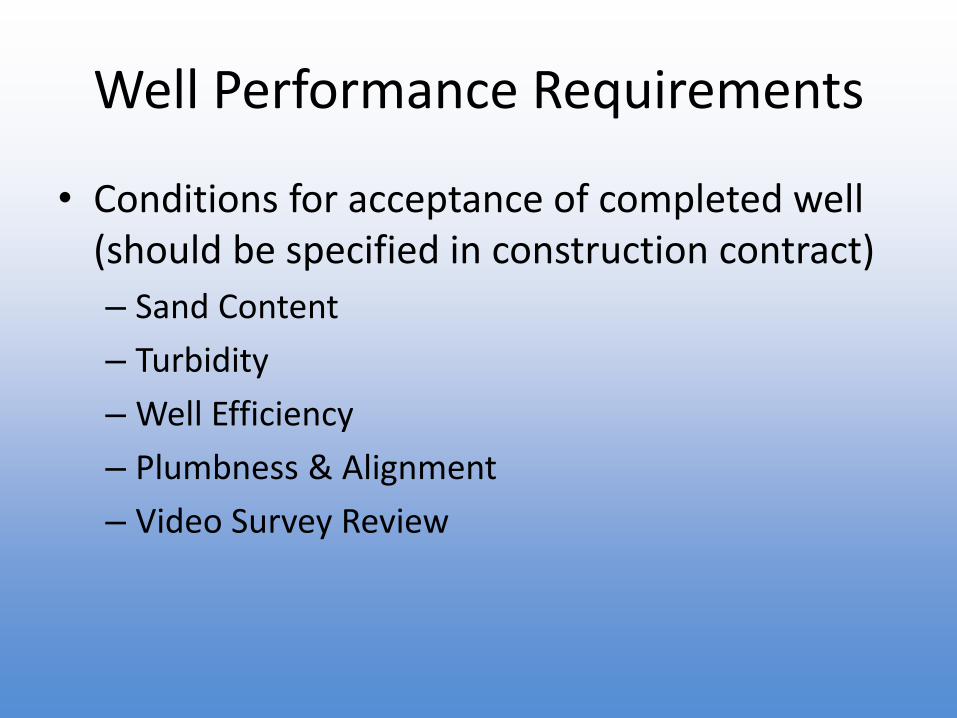
• Well Performance/Acceptance Tests
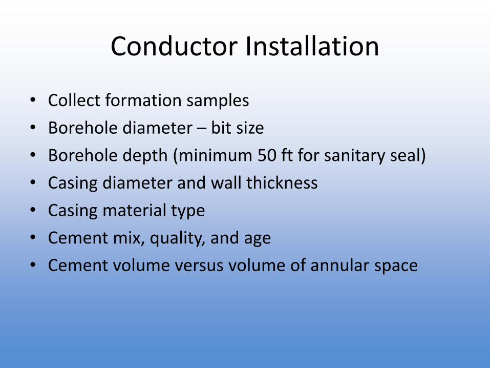
Conductor Installation
• Collect formation samples
• Borehole diameter – bit size
• Borehole depth (minimum 50 ft for sanitary seal)
• Casing diameter and wall thickness
• Casing material type
• Cement mix, quality, and age
• Cement volume versus volume of annular space
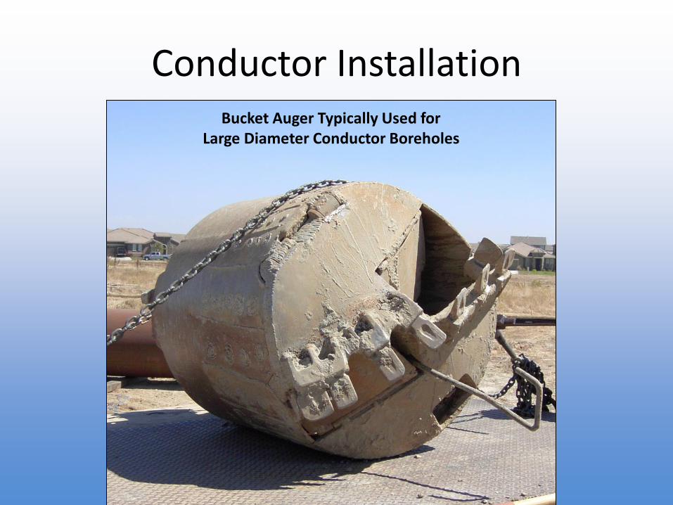
Conductor InstallationBucket Auger Typically Used for
Large Diameter Conductor Boreholes
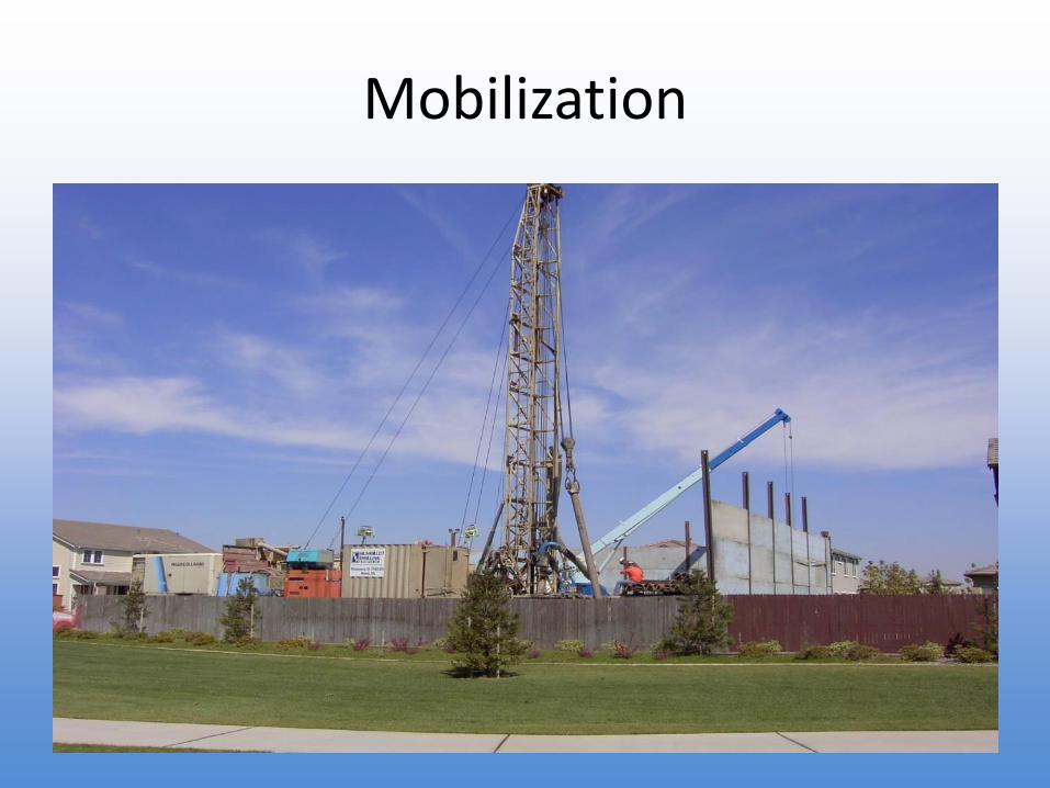
Mobilization
• Document and inventory equipment– Drill Rig Type and Model
– Support Equipment (i.e., backhoe, water truck, pipe trailers, air compressor, etc. )