96
Product: DOC2100E, Revision:17r4 January 2013 Telemetry and data transfer via SATellite TSAT 2100 / 2150 User Guide Hub Station and Remote Terminal Configuration Parameter (MIB) Description
| Date post: | 04-Apr-2018 |
| Category: |
Documents |
| Upload: | nguyenxuyen |
| View: | 215 times |
| Download: | 2 times |

Product: DOC2100E, Revision:17r4
January 2013
Telemetry and data transfer via SATellite
TSAT 2100 / 2150 User Guide
Hub Station and Remote Terminal Configuration Parameter (MIB)
Description

TSAT 2100 / 2150 - Telemetry and data transfer via SATellite
TSAT 2100 / 2150 Configuration Parameter Description, January 2013 Page 2 of 96
Document Status
Product description: Hub Station and Remote Terminal Configuration Parameter Description
Revision Date Reason for change Archive 1 2000.02.02 First Revision U2100E01.DOC
2 2000.06.06 Update to CCU version C22.8.0 U2100E02.DOC
3 2000.08.25 Update to CCU version C22.8.1 U2100E03.DOC
4 2001.06.26 Update to CCU version C23.1.0: Changed UTL_UTILITY_MASK. Changed COM{n}_BIT_RATE. Changed COM{n}_OPTIONS. Changed COM{n}_STREAM_RT. Changed COM{n}_STREAM_RT_PORT. Changed TX_GAIN_OVERRIDE. Described NET_MAX_POLL_PACKETS. NET_GROUPS isn’t Volatile.
U2100E04.DOC
5 2001.09.17 Update to CCU version C23.2.0: Described new COM{n}_DTR_OUT_FUNC. Changed COM{n}_OPTIONS. Described new PHL_TX_GAIN.
U2100E05.DOC
6 2001.10.31 Update to CCU version C23.2.1: Changed PHL_TX_GAIN.
U2100E06.DOC
7 2002.09.09 Update to CCU version C23.5.0. Corrected COM{n}_MAX_PKT_SIZE. Changed + more description COM{n}_PORT_TYPE. More description most COM{n}_ parameters. Described PHL_BITRATE_MODE. Described PHL_TX_RT_FREQUENCY_2. Changed FE_{RX | TX}_LO New POW_LISTEN_HPA_{ON | OFF}. New POW_LISTEN_POLL Changed COM_MAX_APPL_PKT_AGE. New COM_MAX_NETW_PKT_AGE. Changed UTL_{DEBUG | UTILITY}_MASK..
U2100E07.DOC
X 2002.10.08 Update to CCU version C23.5.2. New LCC_{MIN | MAX}_RESET_RETRANS_DELAY. Changed UTL_DEBUG_MASK.. Changed UTL_UTILITY_MASK.
U2100EXX.DOC
X 2002.12.06 Update to CCU version C24.0.0. Changed LCC_{MIN | MAX}_RESET_RETRANS_DELAY. Changed LCC_NO_OF_PACKETIZERS. Changed UTL_UTILITY_MASK. Changed NET_MAX_POLL_PACKETS. Changed MAC_TIMESLOT_MAP_{n}. Changed PHL_TX_GAIN_CAL. Changed PHL_TX_GAIN_REF. Changed SYS_HW_REVISION.
U2100EXX.DOC
8 2003.01.16 Update to CCU version C24.1.0. New PHL_TX_FREQUENCY_ADJUST. Described {MOD | DEMOD}_NCO_NOM. Changed UTL_UTILITY_MASK.
U2100E08.DOC

TSAT 2100 / 2150 - Telemetry and data transfer via SATellite
TSAT 2100 / 2150 Configuration Parameter Description, January 2013 Page 3 of 96
9 2003.01.30 Update to CCU version C24.2.0. New MAC_TIMESLOT_COM{1 | 2}. Described MAC_SLOT_REQ_RSV. Changed COM_MANAGEMENT_PRIORITY. Changed UTL_UTILITY_MASK.
U2100E09.DOC
10 2003.04.01 Upgrade to CCU version C24.2.4. Described MAC_TIMESLOT_MARGIN. Changed MAC_TIMESLOT_COM1. Changed DELTA_SEARCH_FREQUENCY
U2100E10.DOC
11 2003.06.10 Upgrade to CCU version C24.3.0. Changed UTL_UTILITY_MASK. Changed MAC_NO_OF_TIMESLOT_MAPS. New NET_START_POLL_RT.
U2100E11.DOC
12 2003.09.15 Upgrade to CCU version C24.3.1 + C24.4.0. Changed UTL_DEBUG_MASK. Changed COM{n}_FORWARD_CHAR. Changed MAC_TIMESLOT_COM{n}.
U2100E12.DOC
13 2003.12.01 Upgrade to CCU version C24.4.2: Described COM{n}_PKT_TIMEOUT Described LCC_WINDOW_SIZE. New PHL_TX_FREQUENCY_ADJUST_BKUP.
Upgrade to CCU version C24.4.3: Changed LCC_TX_QUE_SIZE. Changed LCC_TX_QUE_SIZE. Changed LCC_TX_QUE_SIZE. Upgrade to CCU version C24.4.4 + C24.4.5:
U2100E13.DOC
14 2004.07.07 Upgrade to CCU version C24.4.6: Changed MAC_TIMESLOT_MARGIN. Described COM{n}_CD_IN_FUNC. Changed / Described PHL_BITRATE_MODE. Described PHL_{INBOUND | OUTBOUND}_IDENTITY. Described PKT_OUTBOUND_SIZE.
U2100E14.DOC
TSAT 2100 / 2150 - Telemetry and data transfer via SATellite
TSAT 2100 / 2150 Configuration Parameter Description, January 2013 Page 4 of 96
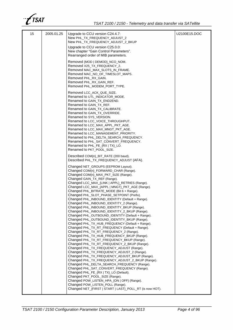
15 2005.01.25 Upgrade to CCU version C24.4.7: New PHL_TX_FREQUENCY_ADJUST_2 New PHL_TX_FREQUENCY_ADJUST_2_BKUP Upgrade to CCU version C25.0.0: New chapter “Gain Control Parameters”. Rearranged order of MIB parameters.
Removed {MOD | DEMOD}_NCO_NOM. Removed X25_TX_FREQUENCY_2. Removed MAC_MAX_SLOTS_IN_FRAME. Removed MAC_NO_OF_TIMESLOT_MAPS. Removed PHL_RX_GAIN. Removed PHL_RX_GAIN_REF. Removed PHL_MODEM_PORT_TYPE.
Removed LCC_ACK_QUE_SIZE. Renamed to UTL_INDICATOR_MODE. Renamed to GAIN_TX_END2END. Renamed to GAIN_TX_REF. Renamed to GAIN_TX_CALIBRATE. Renamed to GAIN_TX_OVERRIDE. Renamed to SYS_VERSION. Renamed to LCC_VOICE_THROUGHPUT. Renamed to LCC_MAX_APPL_PKT_AGE. Renamed to LCC_MAX_MNGT_PKT_AGE. Renamed to LCC_MANAGEMENT_PRIORITY. Renamed to PHL_DELTA_SEARCH_FREQUENCY. Renamed to PHL_SAT_CONVERT_FREQUENCY. Renamed to PHL_FE_{RX | TX}_LO. Renamed to PKT_POOL_SIZE.
Described COM{n}_BIT_RATE (200 baud). Described PHL_TX_FREQUENCY_ADJUST (AFA).
Changed NET_GROUPS (EEPROM Layout). Changed COM{n}_FORWARD_CHAR (Range). Changed COM{n}_MAX_PKT_SIZE (Range). Changed GAIN_TX_REF (Range). Changed LCC_MAX_{LINK | APPL}_RETRIES (Range). Changed LCC_MAX_{APPL | MNGT}_PKT_AGE (Range). Changed PHL_BITRATE_MODE (Bit 6 + Range). Changed PHL_SLOT_PHASE_SETPOINT (Prefix). Changed PHL_INBOUND_IDENTITY (Default + Range). Changed PHL_INBOUND_IDENTITY_2 (Range). Changed PHL_INBOUND_IDENTITY_BKUP (Range). Changed PHL_INBOUND_IDENTITY_2_BKUP (Range). Changed PHL_OUTBOUND_IDENTITY (Default + Range). Changed PHL_OUTBOUND_IDENTITY_BKUP (Range). Changed PHL_TX_HUB_FREQUENCY (Default + Range). Changed PHL_TX_RT_FREQUENCY (Default + Range). Changed PHL_TX_RT_FREQUENCY_2 (Range). Changed PHL_TX_HUB_FREQUENCY_BKUP (Range). Changed PHL_TX_RT_FREQUENCY_BKUP (Range). Changed PHL_TX_RT_FREQUENCY_2_BKUP (Range). Changed PHL_TX_FREQUENCY_ADJUST (Range). Changed PHL_TX_FREQUENCY_ADJUST_2 (Range). Changed PHL_TX_FREQUENCY_ADJUST_BKUP (Range). Changed PHL_TX_FREQUENCY_ADJUST_2_BKUP (Range). Changed PHL_DELTA_SEARCH_FREQUENCY (Range). Changed PHL_SAT_CONVERT_FREQUENCY (Range). Changed PHL_FE_{RX | TX}_LO (Default). Changed PKT_POOL_SIZE (Range). Changed POW_LISTEN_HPA_{ON | OFF} (Range). Changed POW_LISTEN_POLL (Range). Changed NET_{FIRST | START | LAST}_POLL_RT (is now HOT).
U2100E15.DOC

TSAT 2100 / 2150 - Telemetry and data transfer via SATellite
TSAT 2100 / 2150 Configuration Parameter Description, January 2013 Page 5 of 96
15r1 2005.04.12 Upgrade to CCU version C25.0.1 Changed UTL_DEBUG_MASK.
U2100E15r1.DOC
16 2006.01.18 Upgrade to CCU version C25.0.2 Upgrade to CCU version C25.0.3 Described PHL_SLOT_PHASE_MODE. Described PHL_TX_FREQUENCY_ADJUST.
Upgrade to CCU version C25.0.4 Upgrade to CCU version C25.0.5 Upgrade to CCU version C25.1.0 Changed UTL_UTILITY_MASK (Report all packtizer-errors) Changed COM{n}_OPTIONS (Delay between packets) Changed COM{n}_FLOW_CTRL (RTS on while Tx) Changed COM{n}_DTR_OUT_FUNC (DTR on while Tx) New COM_SIGNAL_DATA_DELAY New COM_SIGNAL_HOLD
U21000E16.DOC
16r1 2006.01.28 Upgrade to CCU version C25.1.1 Changed MAC_TIMESLOTS_IN_FRAME (Max 64 => 240)
U2100E16r1.DOC
16r2 2006.09.18 Upgrade to CCU version C25.1.2 Upgrade to CCU version C25.1.3 Changed PHL_TX_FREQUENCY_ADJUST
U2100E16r2.DOC
17 2007.03.19 Upgrade to CCU version C25.1.4 Upgrade to CCU version C25.1.5 Upgrade to CCU version C25.1.6 Changed COM{n}_OPTIONS
U2100E17.DOC
17r1 2007.09.06 Upgrade to CCU version C25.1.7 Upgrade to CCU version C25.1.8 Upgrade to CCU version C25.2.0 Changed LCC_TX_QUE_SIZE (Limits 10…250) New PHL_SWITCH_BACK_TO_MAIN_HUB
U2100E17r1.DOC
17r2 2008.12.10 Upgrade to CCU version C25.2.1 Corrected description UTL_UTILITY_MASK “Named Destinations” for NMS access to MIBs
U2100E17r2.DOC
17r3 2009.03.20 2009.06.04 2010.06.24 2010.07.06 2010.11.02 2010.11.14 2011.01.14 2011.05.23 2011.06.17
Upgrade to CCU version C25.2.2 Upgrade to CCU version C25.2.3 Upgrade to CCU version C25.2.4 Upgrade to CCU version C25.2.5 Upgrade to CCU version C25.2.6 Upgrade to CCU version C25.2.7 Upgrade to CCU version C25.2.8 Upgrade to CCU version C25.2.9 Upgrade to CCU version C25.3.0 New COM{n}_REPLY_TIMEOUT Changed UTL_DEBUG_MASK (DEBUG_CONNECTIONS)
U2100E17r3.DOC
17r4 2011.09.01 2013.01.10
Upgrade to CCU version C25.3.1 Upgrade to CCU version C25.3.2 Described NET_MAX_POLL_PKTS (Described RESET / Switchover) Described LCC_MAX_LINK_RETRIES (Ref NET_MAX_POLL_PKTS).
U2100E17r4.DOC
Approved LHO
Date 2013.01.10
Checked JHA
Date 2013.01.10

TSAT 2100 / 2150 - Telemetry and data transfer via SATellite
TSAT 2100 / 2150 Configuration Parameter Description, January 2013 Page 6 of 96
Documentation Comment Form AV SatCom AS encourages you to comment on the documentation supplied with our products. This information helps us to provide quality products to meet your needs. Edition Date: January 2013 Product: DOC2100E17r4
Please comment on the correctness, completeness, clarity, organisation and usefulness of the manual.
________________________________________________________________________
If you find errors in the manual, please record the page numbers and describe the errors.
________________________________________________________________________ Thank you for your help.
Name___________________________________________________________________
Title_____________________________________________________________________
Company_________________________________________________________________
Address__________________________________________________________________
________________________________________________________________________
Phone (________)________________________________________________________ Following documentation is available for the TSAT 2000/2100 system:
• DOC2000A; System Description • DOC2100A; System Description • DOC2000B; Configuration and Diagnostics Guide; TSAT 2000 / 2100 • DOC2000C; Product Guide • DOC2100C; Product Guide • DOC2000E; Hub Station and Remote Terminal Configuration Parameter Description • DOC2100E; Hub Station and Remote Terminal Configuration Parameter Description • DOC2100F; Hardware Configuration Guide • DOC2010A; Hub Station and Remote Terminal Installation, Operation and Maintenance Guide • DOC2110A; Hub Station and Remote Terminal Installation, Operation and Maintenance Guide • DOC2010B; Supervisory Terminal User Guide; TSAT 2000/2100 • DOC2020A; Remote Terminal Field Installation Guide
AV SatCom AS makes no warranty of any kind with regard to this material, including, but not limited to, the implied warranties of merchantability and fitness for a particular purpose. AV SatCom AS assumes no responsibility for any errors that may appear in this document. AV SatCom AS makes no commitment to update nor to keep current the information contained in this document. Specifications and procedures may change at any time without notice. No part of this document may be copied or reproduced in any form or by any means without prior written consent of AV SatCom AS. Brand names used in this document are the property of their respective owners. Company and product names are trademarks or registered trademarks of their respective companies..

TSAT 2100 / 2150 - Telemetry and data transfer via SATellite
TSAT 2100 / 2150 Configuration Parameter Description, January 2013 Page 7 of 96
Table of contents
1. SCOPE.............................................................................................................................................................. 10
2. GENERAL ....................................................................................................................................................... 10
3. MIB PARAMETER DESCRIPTION............................................................................................................ 11
3.1 COM PARAMETERS ..................................................................................................................................... 11 3.1.1 COM{n}_PORT_TYPE ............................................................................................................................ 11 3.1.2 COM{n}_BIT_RATE ................................................................................................................................ 13 3.1.3 COM{n}_DATA_BITS.............................................................................................................................. 14 3.1.4 COM{n}_STOP_BITS .............................................................................................................................. 14 3.1.5 COM{n}_PARITY..................................................................................................................................... 14 3.1.6 COM{n}_FLOW_CTRL ........................................................................................................................... 15 3.1.7 COM{n}_PRIORITY ................................................................................................................................ 16 3.1.8 COM{n}_PKT_TIMEOUT ....................................................................................................................... 17 3.1.9 COM{n}_FORWARD_CHAR .................................................................................................................. 18 3.1.10 COM{n}_MAX_PKT_SIZE .................................................................................................................... 19 3.1.11 COM{n}_TX_QUEUE_SIZE.................................................................................................................. 21 3.1.12 COM{n}_CD_IN_FUNC........................................................................................................................ 21 3.1.13 COM{n}_DTR_OUT_FUNC.................................................................................................................. 22 3.1.14 COM{n}_REPLY_TIMEOUT................................................................................................................. 23 3.1.15 COM{n}_OPTIONS ............................................................................................................................... 24 3.1.16 COM{n}_STREAM_RT .......................................................................................................................... 28 3.1.17 COM{n}_STREAM_RT_PORT .............................................................................................................. 29 3.1.18 COM{n}_TX_FREQUENCY_2 .............................................................................................................. 30 3.1.19 X25_TX_FREQUENCY_2...................................................................................................................... 30 3.1.20 COM_SIGNAL_DATA_DELAY ............................................................................................................. 31 3.1.21 COM_SIGNAL_HOLD .......................................................................................................................... 31
3.2 GAIN CONTROL PARAMETERS................................................................................................................. 32 3.2.1 PHL_RX_GAIN........................................................................................................................................ 32 3.2.2 PHL_RX_GAIN_REF............................................................................................................................... 32 3.2.3 GAIN_TX_END2END -- PHL_TX_GAIN.............................................................................................. 32 3.2.4 GAIN_TX_REF -- PHL_TX_GAIN_REF ............................................................................................... 33 3.2.5 GAIN_TX_CALIBRATE -- TX_GAIN_CAL ........................................................................................... 34 3.2.6 GAIN_TX_OVERRIDE -- TX_GAIN_OVERRIDE.................................................................................34
3.3 LINK LAYER PARAMETERS....................................................................................................................... 35 3.3.1 LCC_TX_QUE_SIZE ............................................................................................................................... 35 3.3.2 LCC_RETRANS_QUE_SIZE ................................................................................................................... 35 3.3.3 LCC_ACK_QUE_SIZE ............................................................................................................................ 36 3.3.4 LCC_WINDOW_SIZE.............................................................................................................................. 36 3.3.5 LCC_MAX_LINK_RETRIES.................................................................................................................... 37 3.3.6 LCC_MAX_APPL_RETRIES ................................................................................................................... 37 3.3.7 LCC_MAX_APPL_PKT_AGE -- COM_MAX_APPL_PKT_AGE ......................................................... 38 3.3.8 LCC_MAX_MNGT_PKT_AGE -- COM_MAX_NETW_PKT_AGE....................................................... 38 3.3.9 LCC_MANAGEMENT_PRIORITY -- COM_MANAGEMENT_PRIORITY........................................... 38 3.3.10 LCC_{MIN | MAX}_RETRANS_DELAY................................................................................................ 39 3.3.11 LCC_{MIN | MAX}_RESET_RETRANS_DELAY .................................................................................. 39 3.3.12 LCC_NO_OF_PACKETIZERS .............................................................................................................. 40 3.3.13 LCC_VOICE_THROUGHPUT -- COM_VOICE_THROUGHPUT .................................................... 40

TSAT 2100 / 2150 - Telemetry and data transfer via SATellite
TSAT 2100 / 2150 Configuration Parameter Description, January 2013 Page 8 of 96
3.4 MEDIA ACCESS PARAMETERS ................................................................................................................. 41 3.4.1 MAC_MAX_SLOTS_IN_FRAME............................................................................................................. 41 3.4.2 MAC_TIMESLOTS_IN_FRAME.............................................................................................................. 41 3.4.3 MAC_NO_OF_TIMESLOT_MAPS.......................................................................................................... 41 3.4.4 MAC_TIMESLOT_MAP_{n} ................................................................................................................... 42 3.4.5 MAC_TIMESLOT_COM{n}..................................................................................................................... 44 3.4.6 MAC_SLOT_REQ_RSV ........................................................................................................................... 47 3.4.7 MAC_TIMESLOT_LENGTH ................................................................................................................... 48 3.4.8 MAC_TIMESLOT_MARGIN.................................................................................................................... 48
3.5 NETWORK PARAMETERS .......................................................................................................................... 50 3.5.1 NET_NO_OF_RTS................................................................................................................................... 50 3.5.2 NET_RT_ADDRESS................................................................................................................................. 50 3.5.3 NET_{FIRST | LAST}_POLL_RT ............................................................................................................ 51 3.5.4 NET_START_POLL_RT........................................................................................................................... 51 3.5.5 NET_MAX_POLL_PACKETS.................................................................................................................. 52 3.5.6 NET_GROUPS......................................................................................................................................... 52
3.6 PHYSICAL LAYER PARAMETERS............................................................................................................. 53 3.6.1 PHL_BITRATE_MODE ........................................................................................................................... 53 3.6.2 PHL_MODEM_PORT_TYPE .................................................................................................................. 54 3.6.3 PHL_SLOT_PHASE_MODE ................................................................................................................... 55 3.6.4 PHL_SLOT_PHASE_SETPOINT -- SLOTPHASE_SETPOINT ............................................................ 59 3.6.5 PHL_INBOUND_IDENTITY ................................................................................................................... 60 3.6.6 PHL_INBOUND_IDENTITY_2 ............................................................................................................... 60 3.6.7 PHL_INBOUND_IDENTITY_BKUP....................................................................................................... 60 3.6.8 PHL_INBOUND_IDENTITY_2_BKUP................................................................................................... 60 3.6.9 PHL_OUTBOUND_IDENTITY ............................................................................................................... 61 3.6.10 PHL_OUTBOUND_IDENTITY_BKUP................................................................................................. 61 3.6.11 PHL_TX_HUB_FREQUENCY .............................................................................................................. 62 3.6.12 PHL_TX_RT_FREQUENCY.................................................................................................................. 62 3.6.13 PHL_TX_RT_FREQUENCY_2.............................................................................................................. 62 3.6.14 PHL_TX_HUB_FREQUENCY_BKUP.................................................................................................. 63 3.6.15 PHL_TX_RT_FREQUENCY_BKUP ..................................................................................................... 63 3.6.16 PHL_TX_RT_FREQUENCY_2_BKUP ................................................................................................. 63 3.6.17 PHL_TX_FREQUENCY_ADJUST ........................................................................................................ 64 3.6.18 PHL_TX_FREQUENCY_ADJUST_2 .................................................................................................... 65 3.6.19 PHL_TX_FREQUENCY_ADJUST_BKUP............................................................................................ 65 3.6.20 PHL_TX_FREQUENCY_ADJUST_2_BKUP........................................................................................ 65 3.6.21 PHL_SWITCH_BACK_TO_MAIN_HUB............................................................................................... 66 3.6.22 PHL_DELTA_SEARCH_FREQUENCY -- DELTA_SEARCH_FREQUENCY.................................... 67 3.6.23 PHL_SAT_CONVERT_FREQUENCY -- SAT_CONVERT_FREQUENCY......................................... 67 3.6.24 PHL_FE_{RX | TX}_LO -- FE_{RX | TX}_LO.................................................................................... 68 3.6.25 {MOD | DEMOD}_NCO_NOM............................................................................................................. 68
3.7 PACKET PARAMETERS............................................................................................................................... 69 3.7.1 PKT_MAX_SIZE ...................................................................................................................................... 69 3.7.2 PKT_OUTBOUND_SIZE......................................................................................................................... 69 3.7.3 PKT_INBOUND_SIZE............................................................................................................................. 70 3.7.4 PKT_POOL_SIZE -- PKT_NO_OF_MEDIUM_PKTS.......................................................................... 70
3.8 POWER PARAMETERS ................................................................................................................................ 71 3.8.1 POW_WAKEUP_FIRST_TIME ............................................................................................................... 71 3.8.2 POW_LINK_UP_DURATION ................................................................................................................. 71 3.8.3 POW_WAKEUP_INTERVAL................................................................................................................... 72 3.8.4 POW_LISTEN_HPA_ON......................................................................................................................... 73 3.8.5 POW_LISTEN_HPA_OFF....................................................................................................................... 73 3.8.6 POW_LISTEN_POLL .............................................................................................................................. 74

TSAT 2100 / 2150 - Telemetry and data transfer via SATellite
TSAT 2100 / 2150 Configuration Parameter Description, January 2013 Page 9 of 96
3.9 SYSTEM PARAMETERS .............................................................................................................................. 75 3.9.1 SYS_IS_HUB............................................................................................................................................ 75 3.9.2 SYS_COPYRIGHT.................................................................................................................................... 75 3.9.3 SYS_EEPROM_VERSION ....................................................................................................................... 75 3.9.4 SYS_HW_REVISION................................................................................................................................ 75 3.9.5 SYS_VERSION -- SYS_TAG................................................................................................................... 76 3.9.6 SYS_DATE ............................................................................................................................................... 77 3.9.7 SYS_TIME ................................................................................................................................................ 77
3.10 UTILITY PARAMETERS ............................................................................................................................ 78 3.10.1 UTL_DEBUG_MASK ............................................................................................................................ 78 3.10.2 UTL_INDICATOR_MODE -- INDICATOR_MODE ........................................................................... 79 3.10.3 UTL_TRACE_MASK.............................................................................................................................. 80 3.10.4 UTL_UTILITY_MASK............................................................................................................................ 81
4. MIB INDEX SUMMARY............................................................................................................................... 84
5. EEPROM LAYOUT........................................................................................................................................ 87
5.1 VERSION C22.1.0, C22.1.2, C22.1.3, C22.1.4 .................................................................................................. 87 5.2 VERSION C22.2.0, C22.2.1 ............................................................................................................................... 87 5.3 VERSION C22.2.2, C22.2.3, C22.2.4................................................................................................................. 88 5.4 VERSION C22.2.5, C22.2.6 ............................................................................................................................... 88 5.5 VERSION C22.3.0, C22.3.1 ............................................................................................................................... 89 5.6 VERSION C22.4.0, C22.5.0, C22.6.0................................................................................................................. 89 5.7 VERSION C22.7.0, C22.7.1 ............................................................................................................................... 90 5.8 VERSION C22.8.0, C22.8.1, C23.0.0, C23.0.1, C23.1.0, C23.2.0, C23.2.1, C23.3.0, C23.3.1 .......................... 90 5.9 VERSION C23.4.0, C23.5.0, C23.5.1................................................................................................................. 91 5.10 VERSION C23.5.2, C24.0.0 ............................................................................................................................. 91 5.11 VERSION C24.1.0 ........................................................................................................................................... 92 5.12 VERSION C24.2.0, C24.2.1, C24.2.2, C24.2.3, C24.2.4.................................................................................. 92 5.13 VERSION C24.3.0, C24.3.1, C24.4.0, C24.4.1 ................................................................................................ 93 5.14 VERSION C24.4.2, C24.4.3, C24.4.4, C24.4.5, C24.4.6.................................................................................. 93 5.15 VERSION C24.4.7 ........................................................................................................................................... 94 5.16 VERSION C25.0.0, C25.0.1, C25.0.2, C25.0.3, C25.0.4, C25.0.5 ................................................................... 94 5.17 VERSION C25.1.0, C25.1.1, C25.1.2, C25.1.3, C25.1.4, C25.1.5, C25.1.6, C25.1.7, C25.1.8 ........................ 95 5.18 VERSION C25.2.0, C25.2.1, C25.2.2, C25.2.3, C25.2.4, C25.2.5, C25.2.6, C25.2.7, C25.2.8, C25.2.9.......... 95 5.19 VERSION C25.3.0, C25.3.1, C25.3.2............................................................................................................... 96

TSAT 2100 / 2150 - Telemetry and data transfer via SATellite
TSAT 2100 / 2150 Configuration Parameter Description, January 2013 Page 10 of 96
1. SCOPE This document describes the configuration parameters in the .SAT file generated from the TCONFIG.EXE program. The purpose, and legal values, of each parameter is described. 2. GENERAL Unless otherwise stated, all MIB parameters described here are present in the TSAT 2100 / 2150 CCU software versions C22.2.0 to C25.3.2. Generally, unless otherwise stated with the HOT qualifier, the CCU has to be restarted after a MIB variable is changed. Most of the MIB variables will also survive a RESTART of the CCU, unless otherwise stated with the Volatile qualifier. Some of the MIB parameters (i.e. the Backup Frequency parameters) don’t have a CURRENT value. This is indicated with the NoCurrent qualifier. Within the CCU, each MIB variable may have up to 5 different values: • DEFAULT is a table with default values stored in PROM. • EEPROM is a table of MIB variables that will survive a restart of the CCU. MIB variables that
doesn’t have an EEPROM value will not survive a CCU reset, and are also called ‘Volatile’ variables.
• CACHE is a RAM copy of the EEPROM table. It is initialised from the EEPROM values during start-up of the CCU, and it will be copied back to the EEPROM when the operator is doing a FLUSH operation.
• CURRENT is the table with values that is actually used. It is initialised from DEFAULT immediately after CCU reset, and when the variables has been successfully copied from EEPROM to CACHE, it will be initialised from CACHE (over-write the DEFAULT configuration).
• LOCAL is local copies (or transformations) of the CURRENT variables that may be used within some of the software modules. MIB variables that doesn’t have a LOCAL value are also called ‘HOT’ variables. I.e: The operator may change the CURRENT value, and the change will take effect immediately. Otherwise, the operator must change the CACHE value, flush the CACHE to EEPROM and RESET the CCU to activate the new configuration.
From the ‘Management Information Base’ and ‘CCU Configuration’ windows in the Supervisory Terminal the operator may select to: • READ the DEFAULT, CURRENT or CACHE variables. The LOCAL values cannot be read. • WRITE the variable to CURRENT or CACHE. The DEFAULT or LOCAL values cannot be
written. • FLUSH the content of CACHE to EEPROM.
EEPROM
CACHE
CURRENT
LOCAL
Supervisory Terminal
DEFAULT

TSAT 2100 / 2150 - Telemetry and data transfer via SATellite
TSAT 2100 / 2150 Configuration Parameter Description, January 2013 Page 11 of 96
3. MIB PARAMETER DESCRIPTION 3.1 COM PARAMETERS 3.1.1 COM{n}_PORT_TYPE
Ver <= 22.7.1 Default 1, Range 0…2 Ver >= 22.8.0 Default 1, Range 0…2 – HOT
Sets the application type connected to the COM{n} port of the CCU.
Value Mnemonic Description
0 BYTE_STREAM_TYPE Raw byte stream. The input bytes are transferred transparently through the TSAT network.
SERVICE_TYPE TSAT Management Protocol mode.
1 VOICE_TYPE Ver >= 22.2.2: TSAT Management Protocol mode for use by SCADA Voice interface. NOTE: The port is configured as standard SERVICE_TYPE port.
2 ADAPTER_TYPE Ver <= 23.3.1: The port will operate as SERVICE_TYPE. Ver == 23.4.0: Illegal. Operation is not defined. Ver >= 23.5.0: Protocol Adapter port. This mode is applicable at
RT only. At the HUB, the port will operate as standard BYTE_STREAM_TYPE.

TSAT 2100 / 2150 - Telemetry and data transfer via SATellite
TSAT 2100 / 2150 Configuration Parameter Description, January 2013 Page 12 of 96
Depending on the value of COM{n}_PORT_TYPE, the other Port MIB parameters may be used, or not. A summary of actually used Port parameters is given in the table below:
Service Voice-Stream Byte-Stream Adapter Version Port Type 1 0 2
Data Bit Rate COM{n}_BIT_RATE
Data Parity NONE COM{n}_PARITY
Number of Data Bits 8 bit COM{n}_DATA_BITS
Number of Stop Bits 1 bit COM{n}_STOP_BITS
Flow Control COM{n}_FLOW_CTRL & 1 (Not XON/XOFF) COM{n}_FLOW_CTRL
Priority N/A VERY_HIGH COM{n}_PRIORITY
300 ms COM{n}_PKT_TIMEOUT <= 23.3.0 Packet Timeout
300 ms COM{n}_PKT_TIMEOUT >= 23.3.1
DISABLED COM{n}_FORWARD_CHAR <= 23.3.0
DISABLED COM{n}_FORWARD_CHAR 23.3.1 … 24.3.1 Forward Character
DISABLED COM{n}_FORWARD_CHAR AUTO >= 24.4.0
Max Packet Size N/A COM{n}_MAX_PKT_SIZE >= 1000 bytes >= 22.8.0
TX Queue Size COM{n}_TX_QUEUE_SIZE
Action when CD toggle COM{n}_CD_IN_FUNC >= 22.4.0
State of DTR COM{n}_DTR_OUT_FUNC >= 23.2.0
RTS ON while TX COM{n}_FLOW_CTRL + COM_SIGNAL_DATA_DELAY + COM_SIGNAL_HOLD >= 25.1.0
DTR ON while TX COM{n}_DTR_OUT_FUNC + COM_SIGNAL_DATA_DELAY + COM_SIGNAL_HOLD >= 25.1.0
Reply Timeout N/A COM{n}_REPLY_TIMEOUT N/A >= 25.3.0
Option: Merge packets N/A COM{n}_OPTIONS = 1 N/A >= 22.8.0
N/A COM{n}_OPT = 2 N/A <= 23.3.1 Option: Use Packetizer
N/A COM{n}_OPTIONS = 2 N/A >= 23.4.0
Option: Delay between Tx pkt COM{n}_OPTIONS = 4 >= 22.8.0
Option: AT command reply N/A COM{n}_OPTIONS = 8 >= 23.2.0
Option: Error handler DISABLED COM{n}_OPTIONS = 16, 32 >= 22.8.1
Option: Low level loop DISABLED COM{n}_OPTIONS = 64 >= 23.1.0
Option: High level loop DISABLED COM{n}_OPTIONS = 128 >= 23.1.0
Option: Echo loop DISABLED COM{n}_OPTIONS = 192 >= 25.1.6

TSAT 2100 / 2150 - Telemetry and data transfer via SATellite
TSAT 2100 / 2150 Configuration Parameter Description, January 2013 Page 13 of 96
3.1.2 COM{n}_BIT_RATE Ver <= 22.4.0 Default 5, Range 0...9 Ver == 22.5.0 ... 22.7.1 Default 5, Range 0...11 Ver == 22.8.0 ... 23.0.1 Default 7, Range 0...11 – HOT Ver >= 23.1.0 Default 7, Range 0...12 – HOT
Sets the bit rate of the COM{n} port of the CCU.
Value Bit Rate Version
0 300
1 600
2 1200
3 2400
4 4800
5 9600
6 19200
7 38400
8 57600
9 115200
10 50 Ver >= 22.5.0
11 100 Ver >= 22.5.0
12 200 Ver >= 23.1.0 (#) #) Note: 200 baud (value 12) was implemented in version C23.1.0, but the functionality hadn’t
been tested. It didn’t work correctly, and it’s corrected in version C24.4.7.

TSAT 2100 / 2150 - Telemetry and data transfer via SATellite
TSAT 2100 / 2150 Configuration Parameter Description, January 2013 Page 14 of 96
3.1.3 COM{n}_DATA_BITS Ver <= 22.7.1 Default 1, Range 0...1 Ver >= 22.8.0 Default 1, Range 0...1 – HOT
Sets the number of data bits used on the COM{n} port of the CCU.
Value Mnemonic
0 DATA_BITS_7
1 DATA_BITS_8
3.1.4 COM{n}_STOP_BITS Ver <= 22.7.1 Default 1, Range 0...1 Ver >= 22.8.0 Default 1, Range 0...1 – HOT
Sets the number of stop bits used on the COM{n} port of the CCU.
Value Mnemonic
0 STOP_BIT_1
1 STOP_BIT_2
3.1.5 COM{n}_PARITY Ver <= 22.7.1 Default 0, Range 0...2 Ver >= 22.8.0 Default 0, Range 0...2 – HOT
Enable or disable parity check and generation on the COM{n} port of the CCU.
Value Mnemonic
0 PARITY_NONE
1 PARITY EVEN
2 PARITY_ODD

TSAT 2100 / 2150 - Telemetry and data transfer via SATellite
TSAT 2100 / 2150 Configuration Parameter Description, January 2013 Page 15 of 96
3.1.6 COM{n}_FLOW_CTRL Ver <= 22.7.1 Default 0, Range 0...3 Ver == 22.8.0 … 25.0.5 Default 0, Range 0...3 – HOT Ver >= 25.1.0 Default 0, Range 0...5 – HOT
Sets the flow control used on the COM{n} port of the CCU.
Value Mnemonic Description Version
0 NO_FLOW_CTRL No handshake. Data may be lost if any of the internal buffers becomes full.
1, 3 HW_FLOW_CTRL The CCU will set the RTS line when it is prepared to receive data, and stop transmitting data when the CTS signal is inactive.
2 SW_FLOW_CTRL For 7 bits ASCII transfer only. The CCU sends the XOFF character when it is busy, and the XON character when it is prepared to receive data. When the XON or XOFF character is received, the CCU will start or stop transmitting data.
4 RTS_ON_TX Normally RTS is OFF, but it’s set ON while data is transmitted to the port. Timing is controlled by COM_SIGNAL_DATA_DELAY and COM_SIGNAL_HOLD.
Ver >= 25.1.0
5 RTS_OFF_TX Normally RTS is ON, but it’s set OFF while data is transmitted to the port. Timing is controlled by COM_SIGNAL_DATA_DELAY and COM_SIGNAL_HOLD.
Ver >= 25.1.0
See also LCC_TX_QUE_SIZE.

TSAT 2100 / 2150 - Telemetry and data transfer via SATellite
TSAT 2100 / 2150 Configuration Parameter Description, January 2013 Page 16 of 96
3.1.7 COM{n}_PRIORITY Ver <= 22.2.4 Default {1 | 0}, Range 0...1 Ver == 22.2.5 ... 22.7.1 Default 0, Range 0...1 Ver >= 22.8.0 Default 0, Range 0...1 – HOT
Sets the priority of application data received from the COM{n} port on the CCU.
Value Mnemonic Notes
0 LOW_PRIORITY
1 HIGH_PRIORITY
2 SUPER_PRIORITY Is only assigned to a COM port when a Voice Connection is active.
The port priority is only applicable for BYTE_STREAM and ADAPTER ports, and it serves three purposes:
1) Application data from a HIGH_PRIORITY port will be entered in the HIGH_PRIORITY TX queue, which is emptied for transfer to the satellite modem before the LOW_PRIORITY TX queue is searched.
2a) Ver <= 22.2.0: When the size of the TX queue (to satellite modem) is about to exceed the threshold limit, all Byte-Stream COM port(s) are flow controlled. See LCC_TX_QUE_SIZE.
2b) Ver >= 22.2.1: When the size of the TX queue (to satellite modem) is about to exceed the threshold limit, the appropriate COM port(s) are flow controlled. See LCC_TX_QUE_SIZE.
3) RT Ver >= 22.7.0: Used for reservation of Inbound slots in conjunction with the “Slot Request and Reservation Facility”. See MAC_SLOT_REQ_RSV for a description of this facility.
TSAT 2100 / 2150 - Telemetry and data transfer via SATellite
TSAT 2100 / 2150 Configuration Parameter Description, January 2013 Page 17 of 96
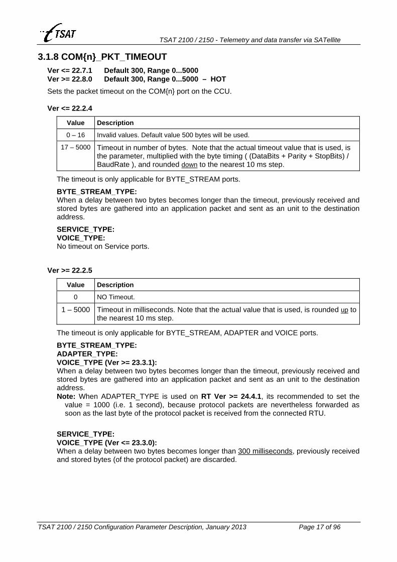
3.1.8 COM{n}_PKT_TIMEOUT Ver <= 22.7.1 Default 300, Range 0...5000 Ver >= 22.8.0 Default 300, Range 0...5000 – HOT
Sets the packet timeout on the COM{n} port on the CCU. Ver <= 22.2.4
Value Description
0 – 16 Invalid values. Default value 500 bytes will be used.
17 – 5000 Timeout in number of bytes. Note that the actual timeout value that is used, is the parameter, multiplied with the byte timing ( (DataBits + Parity + StopBits) / BaudRate ), and rounded down to the nearest 10 ms step.
The timeout is only applicable for BYTE_STREAM ports.
BYTE_STREAM_TYPE: When a delay between two bytes becomes longer than the timeout, previously received and stored bytes are gathered into an application packet and sent as an unit to the destination address.
SERVICE_TYPE: VOICE_TYPE: No timeout on Service ports.
Ver >= 22.2.5
Value Description
0 NO Timeout.
1 – 5000 Timeout in milliseconds. Note that the actual value that is used, is rounded up to the nearest 10 ms step.
The timeout is only applicable for BYTE_STREAM, ADAPTER and VOICE ports.
BYTE_STREAM_TYPE: ADAPTER_TYPE: VOICE_TYPE (Ver >= 23.3.1): When a delay between two bytes becomes longer than the timeout, previously received and stored bytes are gathered into an application packet and sent as an unit to the destination address. Note: When ADAPTER_TYPE is used on RT Ver >= 24.4.1, its recommended to set the
value = 1000 (i.e. 1 second), because protocol packets are nevertheless forwarded as soon as the last byte of the protocol packet is received from the connected RTU.
SERVICE_TYPE: VOICE_TYPE (Ver <= 23.3.0): When a delay between two bytes becomes longer than 300 milliseconds, previously received and stored bytes (of the protocol packet) are discarded.

TSAT 2100 / 2150 - Telemetry and data transfer via SATellite
TSAT 2100 / 2150 Configuration Parameter Description, January 2013 Page 18 of 96
3.1.9 COM{n}_FORWARD_CHAR Ver <= 22.7.1 Default 0, Range (0...255) Ver == 22.8.0 … 24.4.7 Default 0, Range (0...255) – HOT Ver >= 25.0.0 Default 0, Range 0...255 – HOT
Defines the ASCII character that shall force an immediate sending of data (including the forward character) from the COM{n} port defined as: • BYTE_STREAM_TYPE • ADAPTER_TYPE Version == 23.5.0 … 24.3.1. • VOICE_TYPE Version >= 23.3.1. Ver <= 22.2.4
Not Implemented. Ver >= 22.2.5
• Setting the variable to 0 will disable this facility, otherwise it is enabled. • Setting the variable to 126 (‘~’ = 0x7E = SYNC) will enable the IP-frame recognition
facility. An IP-frame consist of SYNC + <max 1540 bytes> + SYNC. Data will only be forwarded if at least one other character is received when the SYNC character is received (to avoid that the packet is forwarded when the Start-SYNC character is received).
Ver >= 22.8.0 The IP-frame recognition facility has been corrected: When the first byte of an IP-frame isn’t SYNC (which may happen when two IP-frames are separated by a single SYNC character), an extra SYNC character is inserted as the first byte of the IP-frame. Furthermore, a Warning is given to the operator if the End-SYNC character isn’t received.
TSAT 2100 / 2150 - Telemetry and data transfer via SATellite
TSAT 2100 / 2150 Configuration Parameter Description, January 2013 Page 19 of 96
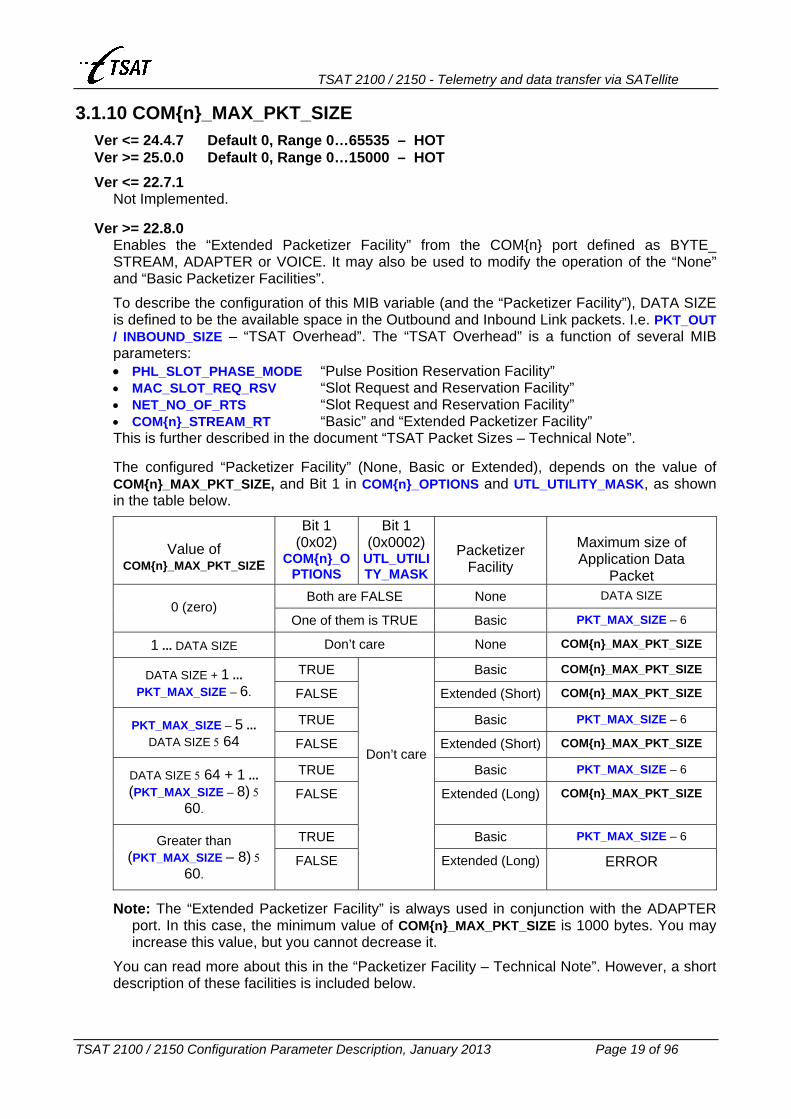
3.1.10 COM{n}_MAX_PKT_SIZE Ver <= 24.4.7 Default 0, Range 0…65535 – HOT Ver >= 25.0.0 Default 0, Range 0…15000 – HOT
Ver <= 22.7.1 Not Implemented.
Ver >= 22.8.0
Enables the “Extended Packetizer Facility” from the COM{n} port defined as BYTE_ STREAM, ADAPTER or VOICE. It may also be used to modify the operation of the “None” and “Basic Packetizer Facilities”.
To describe the configuration of this MIB variable (and the “Packetizer Facility”), DATA SIZE is defined to be the available space in the Outbound and Inbound Link packets. I.e. PKT_OUT / INBOUND_SIZE – “TSAT Overhead”. The “TSAT Overhead” is a function of several MIB parameters: • PHL_SLOT_PHASE_MODE “Pulse Position Reservation Facility” • MAC_SLOT_REQ_RSV “Slot Request and Reservation Facility” • NET_NO_OF_RTS “Slot Request and Reservation Facility” • COM{n}_STREAM_RT “Basic” and “Extended Packetizer Facility” This is further described in the document “TSAT Packet Sizes – Technical Note”. The configured “Packetizer Facility” (None, Basic or Extended), depends on the value of COM{n}_MAX_PKT_SIZE, and Bit 1 in COM{n}_OPTIONS and UTL_UTILITY_MASK, as shown in the table below.
Value of COM{n}_MAX_PKT_SIZE
Bit 1 (0x02)
COM{n}_OPTIONS
Bit 1 (0x0002)
UTL_UTILITY_MASK
Packetizer Facility
Maximum size of Application Data
Packet Both are FALSE None DATA SIZE
0 (zero) One of them is TRUE Basic PKT_MAX_SIZE – 6
1 ... DATA SIZE Don’t care None COM{n}_MAX_PKT_SIZE
TRUE Basic COM{n}_MAX_PKT_SIZE DATA SIZE + 1 ... PKT_MAX_SIZE – 6. FALSE Extended (Short) COM{n}_MAX_PKT_SIZE
TRUE Basic PKT_MAX_SIZE – 6 PKT_MAX_SIZE – 5 ... DATA SIZE 5 64 FALSE Extended (Short) COM{n}_MAX_PKT_SIZE
TRUE Basic PKT_MAX_SIZE – 6 DATA SIZE 5 64 + 1 ... (PKT_MAX_SIZE – 8) 5
60. FALSE Extended (Long) COM{n}_MAX_PKT_SIZE
TRUE Basic PKT_MAX_SIZE – 6 Greater than (PKT_MAX_SIZE – 8) 5
60. FALSE
Don’t care
Extended (Long) ERROR
Note: The “Extended Packetizer Facility” is always used in conjunction with the ADAPTER port. In this case, the minimum value of COM{n}_MAX_PKT_SIZE is 1000 bytes. You may increase this value, but you cannot decrease it.
You can read more about this in the “Packetizer Facility – Technical Note”. However, a short description of these facilities is included below.

TSAT 2100 / 2150 - Telemetry and data transfer via SATellite
TSAT 2100 / 2150 Configuration Parameter Description, January 2013 Page 20 of 96
None Packetizer When a “None Packetized” packet is received from the Application (COM Port), it is immediately queued in the “Link TX Queue”, and later sent on (controlled by Priority and Access Scheme) to the opposite unit. An Application Data packet will always fit into a single TSAT Link packet.
When a “None Packetized” packet is received from the Satellite link, it is immediately queued in the appropriate “COM TX Queue”, and later sent (controlled by COM port flow control) to the connected Application. Basic Packetizer When a “Basic Packetized” packet is received from the Application (COM Port), it is split into several TSAT Link packets, each containing DATA SIZE number of application bytes. All packets are immediately queued in the “Link TX Queue”, and later sent on (controlled by Priority and Access Scheme) to the opposite unit. An Application Data packet will always fit into a single Internal packet, and from 2 to 12 TSAT Link packets. The actual number is given by: RoundUP( (PKT_MAX_SIZE – 6) / DATA SIZE).
When a “Basic Packetized” packet is received from the Satellite link, it is concatenated with already received packets into a single Internal packet. When the last link packet has been received, the Internal packet (containing one Application Data packet) is immediately queued in the appropriate “COM TX Queue”, and later sent (controlled by COM port flow control) to the connected Application.
All “Basic Packetized” packets have a sequence number (from 0 to 15). If a packet is lost on the Satellite link, all other packets within this sequence are discarded, and Warnings are given to the operator. Extended Packetizer The “Extended Packetizer Facility” may operate in two modes: • “Short Sequence” is selected when COM{n}_MAX_PKT_SIZE fits into maximum 64 Link
packets. I.e. RoundUP(COM{n}_MAX_PKT_SIZE / DATA SIZE) is less or equal 64. • “Long Sequence” is selected when the “Short Sequence” mode cannot be selected. In
this case, a 14 bits sequence number is used (range 0 ... 16383), but due to other limitations it cannot be larger than (PKT_MAX_SIZE – 8) 5 60 / DATA SIZE. (I.e. maximum 715 Link packets).
When an “Extended Packetized” packet is received from the Application (COM Port), the CCU is reading it in blocks of DATA SIZE bytes. When one block is received, it is immediately queued in the “Link TX Queue”, and later sent on (controlled by Priority and Access Scheme) to the opposite unit. One data block will always fit into a single TSAT Link packet.
When an “Extended Packetized” packet is received from the Satellite link, it is concatenated with already received packets into maximum 60 internal packets, each containing PKT_MAX_SIZE – 8 bytes. When the last link packet has been received, all the Internal packets (containing the complete Application Data Packet) is immediately queued in the appropriate “COM TX Queue”, and later sent (controlled by COM port flow control) to the connected Application. Note that COM{n}_TX_QUEUE_SIZE must be large enough to hold a complete Application Data Packet (max 60 Internal packets).
If COM{n}_MAX_PKT_SIZE at the originating side is so large that more than 60 Internal packets are needed to store the Application Data Packet at the destination side, the “packetizer” will start to send the first Internal packet(s) to the Application. Therefore, no more than 60 internal packets are queued, but the TSAT network cannot guarantee that the Application Data Packet is delivered to the Application as a continuous stream of bytes.
All “Extended Packetized” packets have a sequence number (“Short Sequence”: from 0 to 63, or “Long Sequence” from 0 to 16383). If a packet is lost on the Satellite link, all other packets within this sequence are discarded, and Warnings are given to the operator.

TSAT 2100 / 2150 - Telemetry and data transfer via SATellite
TSAT 2100 / 2150 Configuration Parameter Description, January 2013 Page 21 of 96
3.1.11 COM{n}_TX_QUEUE_SIZE Ver <= 22.6.0 Default 20, Range 10...50 Ver == 22.7.0 ... 22.7.1 Default 20, Range 10...200 Ver >= 22.8.0 Default 64, Range 10...200 – HOT
Sets the number of application packets that may be stored in the COM{n} port transmitter driver (to the connected application).
3.1.12 COM{n}_CD_IN_FUNC Default 0, Range 0…3 – HOT
Ver <= 22.3.1 Not Implemented.
Ver >= 22.4.0
Controls the interpretation of the CD (Carrier Detect) input signal (pin 1), and what to do when the signal changes.
Value Mnemonic Description
0 CD_IGNORE Ignore CD input.
1 CD_POWER If the sleep mode MIB variable POW_WAKEUP_INTERVAL is greater than zero, the change of CD signal from ON to OFF, and it has been OFF for 1.5 +/– 0.5 seconds, the CCU will start the shut-down sequence and enter sleep mode: HUB: Wait 3 seconds, program the power to be turned ON
after POW_WAKEUP_INTERVAL minutes, and then turning the power OFF.
RT: Wait until the RT doesn’t have any more packets to send to Hub, but maximum 10 seconds. Then a LINK_DISCONNECT message will be sent to the Hub, it will wait 3 seconds, program the power to be turned ON after POW_WAKEUP_INTERVAL minutes (1…10080: i.e. 1 minute … 1 week), and turn the power OFF.
Note 1: Strap SW902 must be connected to enable the power down functions.
Note 2: The power will be turned ON when the CD signal is changing from OFF to ON, or after POW_WAKEUP_INTERVAL minutes have elapsed, whichever occurs first.
Note 3: ON is +5V, OFF is –5V.
2 Not valid.
3 Not valid.

TSAT 2100 / 2150 - Telemetry and data transfer via SATellite
TSAT 2100 / 2150 Configuration Parameter Description, January 2013 Page 22 of 96
3.1.13 COM{n}_DTR_OUT_FUNC Ver <= 25.0.5 Default 0, Range 0…3 – HOT Ver >= 25.1.0 Default 0, Range 0…5 – HOT
Ver <= 22.3.1 Not Implemented (DTR is always ON).
Ver == 22.4.0 … 23.1.0
Not Used (DTR is always ON). Ver >= 23.2.0
Controls the state and behaviour of the DTR (Data Terminal Ready) output signal (pin 4).
Value Mnemonic Description
0 DTR_ON DTR is always ON.
1 DTR_OFF DTR is always OFF, but may be set ON by the Supervisory Terminal. Should be used in conjunction with DIALLED line when the ‘Toggle DCD’ option is selected.
2 DTR_LINK_UP Enable the Link Up detection facility: HUB: Depending of the value of COM{n}_STREAM_RT: • In the range from 1 to NET_NO_OF_RTS: The DTR signal
is set ON when the link to the specified RT is UP. Otherwise, the DTR signal is OFF.
• Other values: The DTR signal is set ON when the link to at least one RT is UP. Otherwise, the DTR signal is OFF.
RT: DTR is ON when the link to Hub is UP. Otherwise, the DTR signal is OFF.
3 DTR_LINK_DOWN Same behaviour as described for the DTR_LINK_UP option above, but the logic is inverted. I.e. The DTR signal is set ON when the link is DOWN.
Ver >= 25.1.0
In additions to the functions above, it’s possible to activate the DTR signal while data is transmitted to the COM port:
Value Mnemonic Description
4 DTR_ON_TX Normally DTR is OFF, but it’s set ON while data is transmitted to the port. Timing is controlled by COM_SIGNAL_DATA_DELAY and COM_SIGNAL_HOLD
5 DTR_OFF_TX Normally DTR is ON, but it’s set OFF while data is transmitted to the port. Timing is controlled by COM_SIGNAL_DATA_DELAY and COM_SIGNAL_HOLD.

TSAT 2100 / 2150 - Telemetry and data transfer via SATellite
TSAT 2100 / 2150 Configuration Parameter Description, January 2013 Page 23 of 96
3.1.14 COM{n}_REPLY_TIMEOUT Default 0, Range 0…60 – HOT
Ver <= 25.2.9 Not Implemented.
Ver >= 25.3.0
The “Reply Timeout” facility is enabled for BYTE_STREAM ports when this value is different to zero. In this case, a timer is started (i.e. COM{n}_REPLY_TIMEOUT [seconds]) each time data is sent to the COM port (from TSAT modem to locally connected equipment). Data from the COM port will only be accepted as long as this timer is running, and sent via satellite link to the HUB. Data received after the timer has expired will be discarded. When bit 8 (0x0100 – DEBUG_CONNECTIONS) in UTL_DEBUG_MASK is enabled, a Warning (Code 55 – Timeout) will be issued whenever data is discarded.
This facility will correct a problem that could occur with double (alternate) communication to Application-Equipment (AE). When the other communication path is much faster than TSAT, the AE could be polled more often and would also reply more often. When reply is feed to both communication paths, TSAT would send all these replies to HUB and possible saturate the inbound link. This problem is now corrected.
.

TSAT 2100 / 2150 - Telemetry and data transfer via SATellite
TSAT 2100 / 2150 Configuration Parameter Description, January 2013 Page 24 of 96
3.1.15 COM{n}_OPTIONS Ver <= 23.0.1 Default 1, Range 0…255 – HOT Ver >= 23.1.0 Default 0, Range 0…255 – HOT
Ver <= 22.7.1 Not Implemented.
Ver == 22.8.0
Controls miscellaneous COM port functions.
Bit Field Mnemonic Comments
0 0x01 COM_OPTION_MERGE_PKTS Byte/Voice-Stream – “None Packetizer”.
1 0x02 COM_OPTION_PCKTIZER_ON Byte/Voice-Stream – “Basic Packetizer”.
2 0x04 COM_OPTION_DELAY_BETWEEN_PKTS Service, Byte/Voice-Stream and Adapter.
3 – 7 0xF8 Not defined. Should be set to zero. COM OPTION MERGE PKTS When enabled, received packets from the COM{n} port will be merged with already existing packets in the “Link TX Queue” (that is waiting to be transmitted on the satellite link). This is a very useful function when we are receiving a lot of small packets from the Application, and is not able to send all of them to the other side before we receive more data from the Application. By this way, all Link packets will be completely filled with Application data, and the load on the satellite link will be minimised. This option is only available for BYTE_STREAM and VOICE ports that are configured to use the “None Packetizer Facility”. COM OPTION PCKTIZER ON When enabled, received packets from the COM{n} port will use the “Basic Packetizer Facility”. This is equally to set Bit 1 (0x0002, UTILITY_WS_PCTIZER_ON) in UTL_UTILITY_MASK, but here you may enable the “Basic Packetizer” for a specified COM port. Setting the bit in UTL_UTILITY_MASK will enable the “Basic Packetizer” for both COM ports. This option is only available for BYTE_STREAM and VOICE ports. See also COM{n}_MAX_PKT_SIZE. COM OPTION DELAY BETWEEN PKTS When enabled, a delay is inserted after each packet has been transmitted to the COM{n} port. A “packet” is in this context: • A single Link packet (maximum PKT_OUT / INBOUND_SIZE – TSAT Overhead bytes), when
the “None Packetizer Facility” is used. • A single Internal packet (maximum PKT_MAX_SIZE – 6 bytes), when the “Basic Packetizer
Facility” is used. • A number of Internal packets (maximum 60 x (PKT_MAX_SIZE – 5) bytes), when the
“Extended Packetizer Facility” is used.
Ver <= 25.0.5: The pause is set equal COM{n}_PKT_TIMEOUT – the time to send the (last) Internal packet at the specified baud rate. The delay will therefore at least be greater than: COM{n}_PKT_TIMEOUT – (PKT_MAX_SIZE – 5) x 8000 / COM{n}_BIT_RATE [ms].
Ver >= 25.1.0: The pause is set equal COM_SIGNAL_HOLD.

TSAT 2100 / 2150 - Telemetry and data transfer via SATellite
TSAT 2100 / 2150 Configuration Parameter Description, January 2013 Page 25 of 96
Ver == 22.8.1 … 23.0.1
Controls miscellaneous COM port functions. More functions are defined, compared to software version C22.8.0.
Bit Field Mnemonic Comments
0 0x01 COM_OPTION_MERGE_PKTS Byte/Voice-Stream – “None Packetizer”.
1 0x02 COM_OPTION_PCKTIZER_ON Byte/Voice-Stream – “Basic Packetizer”.
2 0x04 COM_OPTION_DELAY_BETWEEN_PKTS Service, Byte/-Stream and Adapter.
3 0x08 Not defined. Should be set to zero.
4, 5 0x30 COM_OPTION_ERROR_HANDLER Byte/Voice-Stream and Adapter
6, 7 0xC0 Not defined. Should be set to zero. COM OPTION ERROR HANDLER Two bits are defining what to do when the CCU is receiving Parity, Framing, Overrun and Break errors. These options are only available for BYTE_STREAM, VOICE and ADAPTER ports. • OLD (0x00): Do exactly as older software versions are doing. I.e. when a Parity, Framing
or Overrun error occurred, all previously received bytes (and possible a few bytes received after the error occurred) was discarded. Nothing is sent to the remote unit.
• CONDITIONAL (0x10): When a Parity, Framing, Overrun or Break error occurs, all previously received bytes (not including the erroneous character) are gathered together into one packet and immediately sent to the remote unit. Thereafter, all received bytes are discarded until one of the following happens: a) 10 following bytes are received without any Parity, Framing, Overrun or Break errors. b) 10 seconds has elapsed without receiving any errors. When either a) or b) occurs, the COM port will start to receive characters as normal, and forward them to the remote unit when one of the “Packet Forward” criteria is met.
• IGNORE (0x20): Ignore all Parity, Framing, Overrun and Break errors, and send all received bytes (including the erroneous characters) to the remote unit (when one of the “Packet Forward” criteria is met).
• DISCARD (0x30): Ignore all Parity, Framing, Overrun and Break errors. Discard all bytes received with Parity or Framing errors, and send the remaining bytes to the remote unit. (when one of the “Packet Forward” criteria is met). NB: When the COM{n} port is configured as BYTE_STREAM or ADAPTER with ODD or EVEN Parity, and this option is enabled, it is not possible to connect this port to TCONF (the TSAT Configuration program). Therefore, this option should not be enabled on both COM ports. Otherwise, it may not be possible to configure this RT from a locally connected terminal.
Note: Older software versions are ignoring Break errors, while Ver >= 22.8.1 will handle the Break error in the same way as Overrun errors are handled.

TSAT 2100 / 2150 - Telemetry and data transfer via SATellite
TSAT 2100 / 2150 Configuration Parameter Description, January 2013 Page 26 of 96
Ver == 23.1.0
Controls miscellaneous COM port functions. More functions are defined, compared to software version C23.0.1.
Bit Field Mnemonic Comments
0 0x01 COM_OPTION_MERGE_PKTS Byte/Voice-Stream – “None Packetizer”.
1 0x02 COM_OPTION_PCKTIZER_ON Byte/Voice-Stream – “Basic Packetizer”.
2 0x04 COM_OPTION_DELAY_BETWEEN_PKTS Service, Byte/Voice-Stream and Adapter.
3 0x08 Not defined. Should be set to zero.
4, 5 0x30 COM_OPTION_ERROR_HANDLER Byte/Voice-Stream and Adapter
6 0x40 COM_OPTION_LOW_LEVEL_LOOP Byte-Stream and Adapter.
7 0x80 COM_OPTION_HIGH_LEVEL_LOOP Byte-Stream and Adapter.
COM OPTION LOW LEVEL LOOP When enabled, data received from the satellite link and sent to the BYTE_STREAM or ADAPTER COM port, will be (hardware) looped within the UART device, and handled as it was received from the COM port (i.e. sent back to the other network node). No data will be sent to, or received from, the COM port.
COM OPTION HIGH LEVEL LOOP When enabled, data received from the satellite link and sent to the BYTE_STREAM or ADAPTER COM port, will be (software) looped within the UART device driver, and handled as it was received from the COM port (i.e. sent back to the other network node). Data received from the COM port will be looped back to the COM port.
COM Driver UART
Satellite Link RS 232
COM Driver UART
Satellite Link RS 232

TSAT 2100 / 2150 - Telemetry and data transfer via SATellite
TSAT 2100 / 2150 Configuration Parameter Description, January 2013 Page 27 of 96
Ver >= 23.2.0
Controls miscellaneous COM port functions. More functions are defined, compared to software version C23.1.0.
Bit Field Mnemonic Comments
0 0x01 COM_OPTION_MERGE_PKTS Byte/Voice-Stream – “None Packetizer”.
1 0x02 COM_OPTION_PCKTIZER_ON Byte/Voice-Stream – “Basic Packetizer”.
2 0x04 COM_OPTION_DELAY_BETWEEN_PKTS Service, Byte/Voice-Stream and Adapter.
3 0x08 COM_OPTION_AT_COMMAND_REPLY Byte-Stream with IP-frames
4, 5 0x30 COM_OPTION_ERROR_HANDLER Byte/Voice-Stream and Adapter.
6 0x40 COM_OPTION_LOW_LEVEL_LOOP Byte-Stream or Adapter.
7 0x80 COM_OPTION_HIGH_LEVEL_LOOP Byte-Stream or Adapter.
COM OPTION AT COMMAND REPLY When enabled, data received from the BYTE_STREAM COM port (defined with the “IP frame recognition facility”. See COM{n}_FORWARD_CHAR) will be scanned for AT (modem) commands (I.e. Text string beginning with “AT”). All such AT commands will be handled locally, and the reply “OK<CR>” is sent back to the connected application.
Ver >= 25.1.6
Controls miscellaneous COM port functions. More functions are defined, compared to software version C23.2.0.
Bit Field Mnemonic Comments
0 0x01 COM_OPTION_MERGE_PKTS Byte/Voice-Stream – “None Packetizer”.
1 0x02 COM_OPTION_PCKTIZER_ON Byte/Voice-Stream – “Basic Packetizer”.
2 0x04 COM_OPTION_DELAY_BETWEEN_PKTS Service, Byte/Voice-Stream and Adapter.
3 0x08 COM_OPTION_AT_COMMAND_REPLY Byte-Stream with IP-frames
4, 5 0x30 COM_OPTION_ERROR_HANDLER Byte/Voice-Stream and Adapter.
6 0x40 COM_OPTION_LOW_LEVEL_LOOP Byte-Stream or Adapter.
7 0x80 COM_OPTION_HIGH_LEVEL_LOOP Byte-Stream or Adapter.
6, 7 0xC0 COM_OPTION_ECHO_LOOP Byte-Stream or Adapter.
COM OPTION ECHO LOOP When enabled (i.e. both COM_OPTION_LOW_LEVEL_LOOP and COM_OPTION_HIGH_LEVEL_ LOOP), the following procedure applies: • Data received from the BYTE_STREAM or ADAPTER COM port will be sent to the satellite
network (as normal). • Data received from satellite network to this BYTE_STREAM or ADAPER COM port will be
sent to the COM port (as normal). In addition, the data will be looped and also sent back to the TSAT satellite network.
COM Driver UART
Satellite Link RS 232

TSAT 2100 / 2150 - Telemetry and data transfer via SATellite
TSAT 2100 / 2150 Configuration Parameter Description, January 2013 Page 28 of 96
3.1.16 COM{n}_STREAM_RT Hub+RT Ver <= 23.0.1 Default –1, Range –1...12287 (0x2FFF) – HOT Hub Ver >= 23.1.0 Default –1, Range –1...12287 (0x2FFF) – HOT RT Ver >= 23.1.0 Default –1, Range –1...12287 and 32768...65535 – HOT
If the COM{n} port on the Main Unit is configured as BYTE_STREAM or ADAPTER, this port can be used to transmit and receive Leased Line data (circuit switched protocol). The following configuration is legal:
Value Hex Leased Line Description Hub RT Version
–1 0xFFFF DISABLED (default) YES YES
0 0x0000 From Hub to BROADCAST (all RTs) YES no
n 0x0XXX From Hub to RT n (1 <= n <= NET_NO_OF_RTS) YES no
4096 + n 0x1XXX From Hub to RT-Cluster n YES YES Ver >= 22.2.5
8192 + n 0x2XXX From Hub to GROUP n YES YES
32768 0x8000 From this RT to BROADCAST (all RTs) no YES Ver >= 23.1.0
32768 + n 0x8XXX From this RT to another RT n no YES Ver >= 23.1.0
36864 + n 0x9XXX From this RT to RT-Cluster n no YES Ver >= 23.1.0
40960 + n 0xAXXX From this RT to GROUP n no YES Ver >= 23.1.0
RT: When COM{n}_STREAM_RT is defined on a RT to a value in the range 4096 ... 12287
(0x1000 ... 0x2FFF), data received on this COM port will be sent to the Hub, tagged with the defined GROUP (or RT-Cluster) address. The RT will also be included in the defined GROUP, and hence it is not necessary to set the NET_GROUPS MIB variable. Note: The “Packetizer Facility” cannot be used when this MIB variable is enabled on the RT,
and the Hub and RT software is Ver <= 22.7.1. This error is corrected in Ver >= 22.8.0. RT Ver >= 23.1.0: When COM{n}_STREAM_RT is defined on a RT to a value in the range 32768
... 45055 (0x8000 ... 0xAFFF – the two upper bits are 10), a Leased Line connection is defined between this RT and the specified RT(s) or GROUP (see the table above). Application Data will now be sent from this RT, via the Hub, and directly to another RT (or RTs). Note 1: In this case, the TSAT Overhead is increased with 2 bytes (to include re-route
information). See also the document “TSAT Packet Sizes – Technical Note” Note 2: When COM{n}_STREAM_RT = 0x8000 + NET_RT_ADDRESS (and
COM{n}_STREAM_RT_PORT = n – 1), data received from the COM port will be sent to the Hub, looped back to the RT, and transmitted onto the same COM port. You may use this to verify that the connection to Hub is functioning OK.

TSAT 2100 / 2150 - Telemetry and data transfer via SATellite
TSAT 2100 / 2150 Configuration Parameter Description, January 2013 Page 29 of 96
3.1.17 COM{n}_STREAM_RT_PORT Ver <= 22.2.3 Default 0, Range 0...1 – HOT Ver >= 22.2.4 Default 0, Range 0...3 – HOT
Value Description Version
0 Leased Line COM{n} to/from RT.COM 1.
1 Leased Line COM{n} to/from RT.COM 2.
2 Not defined.
3 Leased Line COM{n} to/from both RT.COM 1 and COM 2. Ver >= 22.2.4 HUB: If the COM{n} port on the Hub Main Unit is configured as BYTE_STREAM or ADAPTER,
and COM{n}_STREAM_RT is defined different to –1, then COM{n}_STREAM_RT_PORT has a legal value, and identifies the COM port number on the RT(s).
RT Ver <= 23.0.1: Not Used. RT Ver >= 23.1.0: If the COM{n} port on the RT Main Unit is configured as BYTE_STREAM or
ADAPTER, and the two upper bits of COM{n}_STREAM_RT is 10 (binary) (i.e. Leased Line from this RT to another RT(s)), COM{n}_STREAM_RT_PORT has a legal value, and identifies the COM port number on the destination RT(s).

TSAT 2100 / 2150 - Telemetry and data transfer via SATellite
TSAT 2100 / 2150 Configuration Parameter Description, January 2013 Page 30 of 96
3.1.18 COM{n}_TX_FREQUENCY_2 Default 0, Range 0...1 – HOT
HUB: Not Used. RT: Enable or disable the transmission of application data from COM{n} on the RTs secondary
TX frequency.
Value Mnemonic Description
0 FALSE Data received from COM{n} are sent to the Master Hub by using the PHL_TX_RT_FREQUENCY.
1 TRUE Data received from COM{n} are sent to the Slave Hub by using the PHL_TX_RT_FREQUENCY_2.
3.1.19 X25_TX_FREQUENCY_2 Default 0, Range 0...2 – HOT
Ver <= 22.2.4 Not Implemented.
Ver == 22.2.5 … 24.4.7
Enable or disable the transmission of X.25 application data on the RTs secondary TX frequency. The variable is only used on RT and Slave Hubs, and should be set equal on the two units. HUB (Master): Not Used. HUB (Slave):
Value Description
0, 1 X.25 data received from the RT are sent to the X.25 processor located at the Master Hub (via the Supervisory Terminal).
2 X.25 data received form the RT are sent to the local X.25 processor.
RT:
Value Description
0 Data received from X.25 are sent to the Master Hub by using the PHL_TX_RT_FREQUENCY.
1, 2 Data received form X.25 are sent to the Slave Hub, using the PHL_TX_RT_FREQUENCY_2.
See also COM{n}_TX_FREQUENCY_2.
Ver >= 25.0.0
Not Implemented (TSAT 2150 isn’t equipped with X.25 processor).

TSAT 2100 / 2150 - Telemetry and data transfer via SATellite
TSAT 2100 / 2150 Configuration Parameter Description, January 2013 Page 31 of 96
3.1.20 COM_SIGNAL_DATA_DELAY
Default 0, Range 0...5000 – HOT
Ver <= 25.0.5 Not Implemented.
Ver >= 25.1.0
Control the timing of RTS or DTR signal. See the description of COM_SIGNAL_HOLD.
3.1.21 COM_SIGNAL_HOLD
Default 0, Range 0...5000 – HOT
Ver <= 25.0.5 Not Implemented.
Ver >= 25.1.0
When the “RTS when TX” facility (see COM{n}_FLOW_CTRL) or “DTR when TX” facility (see COM{n}_DTR_OUT_FUNC) is enabled, the appropriate signal (RTS or DTR) will be set active as long as CCU is transmitting data on this COM port. When both facilities are enabled, the “DTR when TX” will take precedence (i.e. you cannot toggle both RTS and DTR simultaneously). • The appropriate signal will be set active COM_SIGNAL_DATA_DELAY [ms] before the first
data byte is transmitted to the COM port. Timer resolution is 10 ms. • The appropriate signal will be set inactive COM_SIGNAL_HOLD [ms] after the last data
byte have been transmitted to the COM port. Timer resolution is 100 ms.
The value of COM_SIGNAL_HOLD will also affect the timing when COM_OPTION_DELAY_ BETWEEN_PKTS is enabled in COM{n}_OPTIONS.

TSAT 2100 / 2150 - Telemetry and data transfer via SATellite
TSAT 2100 / 2150 Configuration Parameter Description, January 2013 Page 32 of 96
3.2 GAIN CONTROL PARAMETERS 3.2.1 PHL_RX_GAIN
Default 0, (Not used)
Ver <= 24.4.7 Not Used.
Ver >= 25.0.0
Not Implemented. 3.2.2 PHL_RX_GAIN_REF
Default 0, (Not used)
Ver <= 24.4.7 Not Used.
Ver >= 25.0.0
Not Implemented.
3.2.3 GAIN_TX_END2END -- PHL_TX_GAIN Ver <= 23.1.0 Default 0, (Not used) Ver == 23.2.0 Default 0, Range (0...40) – HOT Ver >= 23.2.1 Default 0, Range 0...40 – HOT
Ver <= 23.1.0 Not Used.
Ver >= 23.2.0 Controls the “End-to-End Gain Control” facility, that will be enabled by setting GAIN_TX_END2END greater than zero, while the normal “Automatic Gain Control” is enabled (see GAIN_TX_REF next page). When enabled, the TX gain is adjusted in small steps until the measured TX gain is equal the wanted TX gain given by GAIN_TX_REF + DELTA_GAIN. DELTA_GAIN is in the range from 0 to GAIN_TX_END2END, but maximum 40, and will be changed in small steps: • Incremented – When the signal level received at the other side of the link is < 8.0 dB. • Decremented – When the signal level received at the other side of the link is >= 8.5 dB.
The CCU is detecting the signal level, received at the other side of the link: • The RT will detect when the HUB is receiving this RT below 8.0 dB or above/equal 8.5 dB.
(This information is signalled back from the HUB to all RTs in the SYNC packets). • The HUB will detect when at least one of the RTs is receiving the HUB below 8.0 dB, or all
RTs are receiving the HUB above/equal 8.5 dB. (This information is signalled back from the RTs to the HUB in the POLL_ACK packets).
Note: The MIB parameter is called PHL_TX_GAIN in Ver <= 24.4.7.

TSAT 2100 / 2150 - Telemetry and data transfer via SATellite
TSAT 2100 / 2150 Configuration Parameter Description, January 2013 Page 33 of 96
3.2.4 GAIN_TX_REF -- PHL_TX_GAIN_REF Ver <= 24.4.7 Default 0, Range (80...140) – HOT Ver >= 25.0.0 Default 0, Range 0…255 – HOT
Sets the gain and controls the Automatic Gain Control (AGC) of the TX chain:
Ver <= 23.0.1 Without AGC: By setting GAIN_TX_OVERRIDE different to zero, the AGC is disabled and the
TX gain is fixed at the value given by GAIN_TX_OVERRIDE (range 0...4095). With AGC: By setting GAIN_TX_OVERRIDE to zero, the AGC is enabled. TX gain is initiated
to value 1200, and later adjusted until desired gain (GAIN_TX_REF, range 80...140 – from Front-End calibration sheet) is achieved. See also GAIN_TX_CALIBRATE.
Ver >= 23.1.0 Without AGC: By setting bit 12 (0x1000) in GAIN_TX_OVERRIDE to zero, AND the lower 12
bits (0x0FFF) different to zero (i.e. range 1…4095), the AGC is disabled and the TX gain is fixed at the value given by the lower 12 bits in GAIN_TX_OVERRIDE.
With AGC: By setting bit 12 (0x1000) in GAIN_TX_OVERRIDE to 1, OR the lower 12 bits (0x0FFF) are zero (i.e. value ZERO or range 4096 … 8191), the AGC is enabled. • When bit 12 is “0” (i.e. GAIN_TX_OVERRIDE = 0): TX gain is initialised to a fixed value,
dependent of Software version and Hardware revision: Ver == 23.1.0 … 23.5.2: value 1200. Ver >= 24.0.0 and SYS_HW_REVISION <= 15 (TSAT 2100): value 1500. Ver >= 24.0.0 and SYS_HW_REVISION >= 16 (TSAT 2150): value 2000.
• When bit 12 is “1” (i.e. GAIN_TX_OVERRIDE = 4096 … 8191). TX gain is initialised to the value given by the lower 12 bits in GAIN_TX_OVERRIDE (range 0...4095).
The TX gain is later adjusted until desired gain (GAIN_TX_REF, range 80...140 – from Front-End calibration) is achieved. See also GAIN_TX_END2END and GAIN_TX_CALIBRATE. HUB: TX gain is measured, and possible adjusted, in each slot. RT: Depending on bit 13 (0x2000) in GAIN_TX_OVERRIDE. The TX gain is measured,
and possible adjusted: • When bit 13 is “0”: When the RT is sending a packet to the Hub, AND no packet
was sent in the previous slot. • When bit 13 is “1”: Each time the RT is sending a packet to the Hub.
Note: The MIB parameter is called PHL_TX_GAIN_REF in Ver <= 24.4.7.

TSAT 2100 / 2150 - Telemetry and data transfer via SATellite
TSAT 2100 / 2150 Configuration Parameter Description, January 2013 Page 34 of 96
3.2.5 GAIN_TX_CALIBRATE -- TX_GAIN_CAL Default 0, Range 0...255 – HOT
Controls the Automatic Gain Control (AGC) of the TX chain:
The MIB variable is used to calibrate the TX gain. This is the expected measured TX gain when, in calibrate mode, HPA simulates 25 dBm gain by putting a pre-set voltage to the V2F converter in HPA. See also GAIN_TX_REF. Ver >= 24.0.0
The calibration of AGC isn’t applicable in TSAT 2150, and the CURRENT value of GAIN_TX_CALIBRATE is therefore always initialised to ZERO after restart when SYS_HW_REVISION >= 16.
Note: The MIB parameter is called TX_GAIN_CAL in Ver <= 24.4.7.
3.2.6 GAIN_TX_OVERRIDE -- TX_GAIN_OVERRIDE Ver <= 23.0.1 Default 0, Range 0... 4095 (0x0FFF) – HOT Ver >= 23.1.0 Default 0, Range 0...16383 (0x3FFF) – HOT
Controls the Automatic Gain Control (AGC) of the TX chain: The operation is described by GAIN_TX_REF. Ver <= 23.0.1
Bits Field Value Description
0 – 11 0x0FFF 0 – 4095
Fixed TX gain. (0 => AGC).
12 – 15 0xF000 0 – 15 Not used.
Ver >= 23.1.0 Bits Field Value Description
0 – 11 0x0FFF 0 – 4095
Initial OR fixed TX gain.
12 0x1000 0 – 1 Use initial TX gain.
13 0x2000 0 – 1 Measure TX gain after each sent packet (RT only). 14 – 15 0xC000 0 – 3 Not used.
Note: The MIB parameter is called TX_GAIN_OVERRIDE in Ver <= 24.4.7.

TSAT 2100 / 2150 - Telemetry and data transfer via SATellite
TSAT 2100 / 2150 Configuration Parameter Description, January 2013 Page 35 of 96
3.3 LINK LAYER PARAMETERS 3.3.1 LCC_TX_QUE_SIZE
Ver <= 24.4.2 Default 40, Range 1... 50 Ver == 24.4.3 … 25.1.8 Default 40, Range 1...250 Ver >= 25.1.9 Default 40, Range 10...250
Sets the maximum number of packets that may be stored in the satellite link Transmission Queue before transmission. NOTE: The flow control of Byte-Stream COM ports (COM{n}_FLOW_CTRL), and Application data from the Supervisory Terminal, are controlled by the number of packets in the Transmission Queue. See also COM{n}_PRIORITY. Ver <= 22.2.0
PRIORITY Flow Control ON Flow Control OFF
0 = LOW_PRIORITY Size > Max – 15 packets
Size < 5 packets
1 = HIGH_PRIORITY Size > Max – 5 packets
Size < 5 packets
Ver == 22.2.1 … 22.8.1
PRIORITY Flow Control ON Flow Control OFF
0 = LOW_PRIORITY Size > 50 % Size <= 30 %
1 = HIGH_PRIORITY Size > 70 % Size <= 50 %
2 = SUPER_PRIORITY Size > 90 % Size <= 70 % Ver == 23.0.0 … 23.3.1
PRIORITY Flow Control ON Flow Control OFF
0 = LOW_PRIORITY Size > 30 % Size <= 30 %
1 = HIGH_PRIORITY Size > 50 % Size <= 50 %
2 = SUPER_PRIORITY Size > 70 % Size <= 70 %
This scheme causes a lot of FLOW_{ON | OFF} messages to the Supervisory Terminal, and the Satellite Link Transmission Queue is normally never filled more than 50 %.
Ver >= 23.4.0 Normally, the scheme used by version C22.2.1 … C22.8.1 is used, but it’s also possible to enable the scheme used by version C23.0.0 … C23.3.1 by setting bit 18 in UTL_UTILITY_MASK (0x0004.0000 – UTILITY_NO_THRESHOLD_LINK_TX_QUEUE).
3.3.2 LCC_RETRANS_QUE_SIZE Ver <= 22.7.1 Default 20, Range 1... 50 Ver == 22.8.0 … 24.4.2 Default 32, Range 1... 50 Ver >= 24.4.3 Default 32, Range 1...250
Sets the maximum number of packets that may be stored in the satellite link Retransmission Queue; i.e.: packets that are transmitted, but not acknowledged yet. See also LCC_WINDOW_SIZE.

TSAT 2100 / 2150 - Telemetry and data transfer via SATellite
TSAT 2100 / 2150 Configuration Parameter Description, January 2013 Page 36 of 96
3.3.3 LCC_ACK_QUE_SIZE Ver <= 24.4.2 Default 20, Range 1... 50 Ver >= 24.4.3 Default 20, Range 1...250
Sets the maximum number of RTs that may be stored in the satellite link Info Acknowledge Queue; i.e. waiting to transmit INFO_ACK to the RT. Ver <= 22.6.0
HUB: Any non-zero value is valid, but normally it should at least be 10. RT: Any non-zero value is valid, but it is no reason to set it greater than 1, as the RT has
only 1 link to the Hub. Ver == 22.7.0 … 24.4.7
HUB: Any non-zero value is valid, but normally it should at least be 10. RT: Not Used (the RT has only 1 link to the Hub).
Ver >= 25.0.0
Not Implemented. The value is hard-coded to 1 on the RT, while HUB will set the value equal NET_NO_OF_RTS.
3.3.4 LCC_WINDOW_SIZE Ver <= 22.6.0 Default 7, Range 1...7 Ver >= 22.7.0 Default 16, Range 2...32 – HOT
Sets the maximum number of satellite link packets that may be outstanding before an acknowledge (INFO_ACK) from the remote side is required. The packet sequence numbering is only used in conjunction with the “Secure Link Facility”. See LCC_MAX_APPL_RETRIES and LCC_MAX_LINK_RETRIES. Please also note the following: • The actual number of outstanding packets is 1 less than the value indicated by
LCC_WINDOW_SIZE. • To utilise the full satellite link throughput capacity, LCC_WINDOW_SIZE should be 1 greater
than the round-trip delay (measured in number of packets). The round-trip delay is from 3 to 24 slots, depending on Satellite Link Rate and Packet Size.
• To utilise the full window size, the LCC_RETRANS_QUE_SIZE must also be greater or equal LCC_WINDOW_SIZE.
Ver 22.7.0 … 23.0.1
NB: Piggy-back acknowledge is not supported, so you must expect a decreased throughput when you are transferring large files in both directions (RT ∏ Hub, and Hub ∏ RT) simultaneously.
Ver >= 24.2.2
HUB: The Hub will send its CURRENT value of LCC_WINDOW_SIZE to the RTs in the outbound LINK_RESET and LINK_ACK packets.
RT: Not used. The RTs will use the value obtained from Hub.

TSAT 2100 / 2150 - Telemetry and data transfer via SATellite
TSAT 2100 / 2150 Configuration Parameter Description, January 2013 Page 37 of 96
3.3.5 LCC_MAX_LINK_RETRIES Ver <= 24.4.7 Default 5, Range (0...255) – HOT Ver >= 25.0.0 Default 5, Range 0...255 – HOT
Ver <= 22.2.4 The variable is HOT Volatil, with default value 5, and is applicable on both Hub and RT. Sets the maximum number of retransmissions (from 0 to 255) used by NETWORK layer (TSAT management) packets: I.e. “Secure Link” or not. See also LCC_MAX_APPL_RETRIES.
Ver >= 22.2.5 The maximum number of retransmissions used by NETWORK layer packets is hardcoded to 5. The variable is HOT, with default value 5, and sets the maximum number of attempts to retransmit a management LINK layer LINK_RESET packet. May be set to any value between 0 and 255. HUB: The Hub will stop re-transmitting LINK_RESET packets to the RT after this number of
retransmissions, provided the value is greater than zero. In the latter case, it will never stop re-transmitting LINK_RESET packets to the RT.
RT: When the RT has retransmitted this number of LINK_RESET packets to the Hub without
receiving a LINK_ACK packet, or it has received more than this number + 1 LINK_RESET packets from the Hub, it will assume that something is wrong in the TX chain and RESET itself. See also NET_MAX_POLL_PACKETS.
3.3.6 LCC_MAX_APPL_RETRIES Ver <= 24.4.7 Default 0, Range (0...255) – HOT Ver >= 25.0.0 Default 0, Range 0...64 – HOT
The “Secure Link Facility” is enabled by setting LCC_MAX_APPL_RETRIES greater than zero. This sets the maximum number of attempts to retransmit an APPLICATION layer (with application data) packet. It may be set to any value between 0 and 255. Multi destination (Broadcast and Group addressing from Hub to RT) packets will never be retransmitted. When the packet has been retransmitted this number of times, the link is assumed to be DOWN, and the Hub and RT will try to open the link with the exchange of LINK_RESET / LINK_ACK packets. The packet will be retransmitted when the link has been opened. See also LCC_MAX_APPL_PKT_AGE.
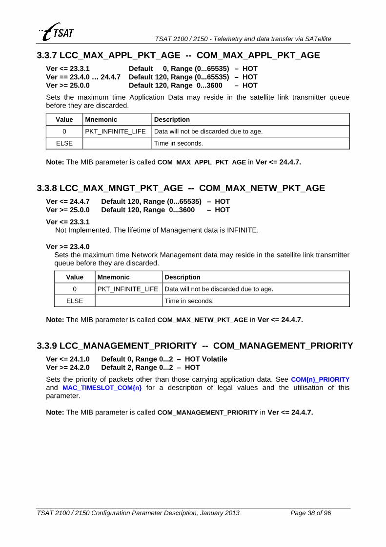
TSAT 2100 / 2150 - Telemetry and data transfer via SATellite
TSAT 2100 / 2150 Configuration Parameter Description, January 2013 Page 38 of 96
3.3.7 LCC_MAX_APPL_PKT_AGE -- COM_MAX_APPL_PKT_AGE Ver <= 23.3.1 Default 0, Range (0...65535) – HOT Ver == 23.4.0 … 24.4.7 Default 120, Range (0...65535) – HOT Ver >= 25.0.0 Default 120, Range 0...3600 – HOT
Sets the maximum time Application Data may reside in the satellite link transmitter queue before they are discarded.
Value Mnemonic Description
0 PKT_INFINITE_LIFE Data will not be discarded due to age.
ELSE Time in seconds. Note: The MIB parameter is called COM_MAX_APPL_PKT_AGE in Ver <= 24.4.7.
3.3.8 LCC_MAX_MNGT_PKT_AGE -- COM_MAX_NETW_PKT_AGE Ver <= 24.4.7 Default 120, Range (0...65535) – HOT Ver >= 25.0.0 Default 120, Range 0...3600 – HOT
Ver <= 23.3.1 Not Implemented. The lifetime of Management data is INFINITE.
Ver >= 23.4.0
Sets the maximum time Network Management data may reside in the satellite link transmitter queue before they are discarded.
Value Mnemonic Description
0 PKT_INFINITE_LIFE Data will not be discarded due to age.
ELSE Time in seconds. Note: The MIB parameter is called COM_MAX_NETW_PKT_AGE in Ver <= 24.4.7.
3.3.9 LCC_MANAGEMENT_PRIORITY -- COM_MANAGEMENT_PRIORITY Ver <= 24.1.0 Default 0, Range 0...2 – HOT Volatile Ver >= 24.2.0 Default 2, Range 0...2 – HOT
Sets the priority of packets other than those carrying application data. See COM{n}_PRIORITY and MAC_TIMESLOT_COM{n} for a description of legal values and the utilisation of this parameter. Note: The MIB parameter is called COM_MANAGEMENT_PRIORITY in Ver <= 24.4.7.

TSAT 2100 / 2150 - Telemetry and data transfer via SATellite
TSAT 2100 / 2150 Configuration Parameter Description, January 2013 Page 39 of 96
3.3.10 LCC_{MIN | MAX}_RETRANS_DELAY Ver <= 22.6.0 Default {20 | 50}, Range 1...600 Ver == 22.7.0 ... 22.7.1 Default {20 | 50}, Range 1...600 – HOT Ver >= 22.8.0 Default {40 | 60}, Range 1...600 – HOT
Lost packets on the satellite link are retransmitted after a random delay in this range, provided that “Secure Link” is enabled (see LCC_MAX_LINK_RETRIES and LCC_MAX_APPL_RETRIES). The interval is doubled after 3 retransmissions. The values are given in 1/10 seconds, and are only applicable for NETWORK and APPLICATION layer packets. Values below 7 (i.e. 0.7 seconds) shall not be used, as the round-trip delay is approximately 0.7 seconds.
LINK layer packets (i.e. LINK_RESET) retransmission delays are controlled by LCC_{MIN | MAX}_RESET_RETRANS_DELAY (default 10 ... 20 seconds).
3.3.11 LCC_{MIN | MAX}_RESET_RETRANS_DELAY Ver == 23.5.2 Default {10 | 20}, Range (1...255) – HOT Ver >= 24.0.0 Default {10 | 20}, Range 5...255 – HOT
Lost LINK_RESET packets on the satellite link are retransmitted after a random delay in this range. The interval is doubled after 3 retransmissions. Ver <= 23.5.1
Not implemented. The parameter values are hard-coded, and LINK_RESET packets are always retransmitted after 10 … 20 seconds.
Ver >= 23.5.2 The values are given in seconds.

TSAT 2100 / 2150 - Telemetry and data transfer via SATellite
TSAT 2100 / 2150 Configuration Parameter Description, January 2013 Page 40 of 96
3.3.12 LCC_NO_OF_PACKETIZERS Ver <= 23.5.2 Default 10, Range 1... 50 Ver >= 24.0.0 Default 10, Range 1...250
Sets the number of packetized packets (Application or Management packets that have been split into several smaller satellite link packets), that may be handled simultaneously by the Hub and RT.
3.3.13 LCC_VOICE_THROUGHPUT -- COM_VOICE_THROUGHPUT Default 4800, Range 0...10000 – HOT
Ver <= 22.2.1 Not Implemented.
Ver >= 22.2.2
Sets the throughput that shall be reserved on the Inbound link for a RT when a Voice connection is active. Default value is 4800 [bits/sec].
Note: The MIB parameter is called COM_VOICE_THROUGHPUT in Ver <= 24.4.7.

TSAT 2100 / 2150 - Telemetry and data transfer via SATellite
TSAT 2100 / 2150 Configuration Parameter Description, January 2013 Page 41 of 96
3.4 MEDIA ACCESS PARAMETERS 3.4.1 MAC_MAX_SLOTS_IN_FRAME
Default 16, Range 2...64
Ver <= 24.4.7 Sets the maximum number of Media Access timeslots that may be assigned to a frame. The MAC_TIMESLOTS_IN_FRAME may never exceed this value.
Ver >= 25.0.0
Not Implemented. Value is hard-coded to maximum 64 Media Access timeslots.
3.4.2 MAC_TIMESLOTS_IN_FRAME Ver <= 25.1.0 Default 16, Range 2... 64 – HOT Ver >= 25.1.1 Default 16, Range 2...240 – HOT
HUB: Sets the number of Media Access timeslots in a frame. The value must be in the range from 2 to MAC_MAX_SLOTS_IN_FRAME. Note that when the Hub is connected to the Supervisory Terminal, this MIB variable will be over-written by the value configured in the Supervisory Terminal.
RT: The MIB variable is not used on the RT, as the current number of timeslots in a frame is
distributed from the Hub to all RTs in every SYNC packet.
3.4.3 MAC_NO_OF_TIMESLOT_MAPS Ver <= 22.2.4 Default 5, Range 1...5 Ver == 22.2.5 … 24.2.4 Default 4, Range 4...16 Ver >= 24.3.0 Default 5, Range 5...16
Ver <= 22.6.0 HUB: Not Used. RT: Sets the number of different Media Access Strategies that may be stored in an RT. The
Supervisory Terminal can configure only 4 of these Access Schemes.
Ver == 22.7.0 … 24.2.4 Sets the number of different Media Access Strategies that may be stored in the Hub and RTs. The Supervisory Terminal can configure only 4 of these Access Schemes.
Ver == 24.3.0 … 24.4.7
Sets the number of different Media Access Strategies that may be stored in the Hub and RTs. The Supervisory Terminal can configure only 5 of these Access Schemes.
Ver >= 25.0.0
Not Implemented. Value is hard-coded to maximum 5 Media Access Strategies.

TSAT 2100 / 2150 - Telemetry and data transfer via SATellite
TSAT 2100 / 2150 Configuration Parameter Description, January 2013 Page 42 of 96
3.4.4 MAC_TIMESLOT_MAP_{n} Ver <= 22.2.4 {0} Default 1, Range (1...0xFFFF.FFFF) Ver == 22.2.5 ... 22.6.0 {0+2 | 1+3} Default {1 | 2}, Range (1...0xFFFF.FFFF) Ver == 22.7.0 ... 23.5.2 {0+2 | 1+3} Default {1 | 2}, Range (1...0xFFFF.FFFF) – HOT Ver >= 24.0.0 {0+2 | 1+3} Default {1 | 2}, Range (0...0xFFFF.FFFF) – HOT HUB:
Ver <= 22.6.0 Not Used.
Ver >= 22.7.0 For each access scheme, these MIB variables defines the Inbound slots which are possible to reserve (temporary) by any of the RTs in conjunction with the “Slot Request and Reservation” facility. See MAC_SLOT_REQ_RSV for a description of this facility. The coding of these parameters is the same as for the RTs (described below), and the cycle is one more than MAC_TIMESLOTS_IN_FRAME (avoiding that any of the RTs are totally excluded from the network when TDMA is used and other RTs are reserving Inbound slots).
RT: The RTs default Media Access Strategy number {n} is represented by this 32 bits MIB
parameter in a packet format. The parameter consists of a 17 elements array:
bit 31
bit 30
bit 29,28
bit 27,26
bit 25,24
bit 23,22
bit 21,20
bit 19,18
bit 17,16
bit 15,14
bit 13,12
bit 11,10
bit 9,8
bit 7,6
bit 5,4
bit 3,2
bit 1,0
17 16 15 14 13 12 11 10 9 8 7 6 5 4 3 2 1
where each of the elements may have one of the following values:
Value Mnemonic Description
0 RESERVED_TIME_SLOT No packets may be sent in this slot
1 LOW_PRIORITY_TIMESLOT Low-, High- and Super-priority packet may be sent
2 HIGH_PRIORITY_TIMESLOT High- and Super-priority packets may be sent
3 SUPER_PRIORITY_TIMESLOT Only Super-priority packets may be sent
Exception: Element 16 and 17 may only have values 0 or 1 (as they are represented by a single bit). The first non-zero element found (searching from MSB to LSB) is recognised as the start of the access right list. The rest of the elements (from MSB to LSB) are repeated in the default Media Access table from Slot[0] up to Slot[MAC_MAX_SLOTS_IN_FRAME]. If only the 1st element is present, this value is repeated in all slots. Examples: 0x0000.0001 gives the Time Slot Map: 1,1,1,1,1,1...... 0x0000.0011 gives the Time Slot Map: 0,1,0,1,0,1...... 0x0000.0014 gives the Time Slot Map: 1,0,1,0,1,0...... 0x0000.0102 gives the Time Slot Map: 0,0,0,2,0,0,0,2...... 0x8000.0001 gives the Time Slot Map: 0,0,0,0,0,0,0,0,0,0,0,0,0,0,0,1,0,0,0......

TSAT 2100 / 2150 - Telemetry and data transfer via SATellite
TSAT 2100 / 2150 Configuration Parameter Description, January 2013 Page 43 of 96
Manual procedure to calculate MAC_TIMESLOT_MAP_{n}
Example 1 Example 2
Decide the slot access scheme for each RT. From 1 to 16 slots may be included in the pattern, and each slot may be represented by code 0, 1, 2 or 3 (base 4). The chosen pattern will be repeated for all slots in the frame (also when the frame consists of more than 16 slots).
0,0,1,0,2,3
0,0,1,0,2,3,0,0,1,0,2,3......
0,1
0,1,0,1,0,1......
Prefix the pattern with ‘1’. 1,0,0,1,0,2,3 1,0,1 Convert to binary digits. 01, 00, 00, 01, 00, 10, 11 01, 00, 01 Arrange in groups of 4 binary digits. 01, 0000, 0100, 1011 01, 0001 Convert each group to hex digit. 1, 0, 4, B 1, 1 Convert the digits to hex number. 104B (hex) 11 (hex) Convert to decimal number. 4171 (dec) 17 (dec) Program MAC_TIMESLOT_MAP_{n} with: 4171 17
Ver <= 22.2.4
{n} = 0. (I.e. only one MIB variable) Note: It’ only possible to set the repeat pattern from 1 to 15 slots. The 16th slot is ignored.
Ver >= 22.2.5
{n} = 0, 1, 2 or 3 (I.e. 4 different MIB variables) When MAC_TIMESLOT_MAP_{n} has the special value 0xFFFF.FFFF (–1), the RT initiates the Media Access Map {n} to default values, so that each RT is reserved equal number of slots. Media Access Map 0 and 1 will distribute the access rights among all RTs (from 1 to NET_NO_OF_RTS), while Media Access Map 2 and 3 will distribute the access rights among all RTs within a RT-Cluster (from NET_FIRST_POLL_RT to NET_LAST_POLL_RT). When MAC_TIMESLOT_MAP_{n} has the special value 0xFFFF.FFFE (–2), the same procedure apply as described above, but only RTs which are reported UP (by the Hub) are included in the Media Access Map.

TSAT 2100 / 2150 - Telemetry and data transfer via SATellite
TSAT 2100 / 2150 Configuration Parameter Description, January 2013 Page 44 of 96
3.4.5 MAC_TIMESLOT_COM{n} Ver <= 24.2.1 Default {0|0}, Range 0...15 – HOT Ver == 24.2.2 … 24.3.1 Default {1|0}, Range 0...15 – HOT Ver >= 24.4.0 Default {1|1}, Range 0...15 – HOT
Ver <= 24.1.0 Not Implemented.
Ver >= 24.2.0
HUB: Not used.
RT: The RT’s slot access is controlled by both “Allowance and Priority” (see MAC_TIMESLOT_MAP_{n}), AND “Source of Data”. Both requirements must be fulfilled, in order for the RT to send a packet. I.e. The packet must have a Priority >= the priority of the current slot in Slot Access Schemes, AND the source of the packet must match the allowed source of data (COM1, COM2 or Management) of the current slot. The allowed source of data is controlled by these two MIB parameters MAC_TIMESLOT_COM{n}.
MAC_ TIMESLOT_
COM2
MAC_ TIMESLOT_
COM1 Source of Data Version
0 0 Data from both COM1, COM2 and Management is allowed to be sent in all enabled slots.
0 1 … 15 Only data from COM1 is allowed to be sent in all enabled slots.
1 … 15 0 Only data from COM2 is allowed to be sent in all enabled slots.
1 1 Only data from COM1 and COM2 are allowed to be sent in all enabled slots
>= 24.4.0
ELSE The operation is dependent of COM{n}_TX_FREQUENCY_2, COM{n}_PRIORITY and Slot Access Schemes (MAC_TIMESLOT_MAP_{n}), as described below.
When both MAC_TIMESLOT_COM1 and MAC_TIMESLOT_COM2 are greater than zero, and at least one of them is greater than 1 (Ver >= 24.4.0), the rules on the next page apply:

TSAT 2100 / 2150 - Telemetry and data transfer via SATellite
TSAT 2100 / 2150 Configuration Parameter Description, January 2013 Page 45 of 96
• When COM1_TX_FREQUENCY_2 is different to COM2_TX_FREQUENCY_2 (I.e. the two
COM ports are sending on different inbound carriers – Multi Inbound Links): - Both COM1 and COM2 (but not Management) is allowed to send in all enabled slots. - The values of MAC_TIMESLOT_COM{n} are don’t care, as long as both are > zero.
• When COM1_PRIORITY is different to COM2_PRIORITY (I.e. one of the COM ports is sending at LOW priority, while the other is sending at HIGH priority), AND both LOW- and HIGH-priority slots are defined in the current Access Scheme: - The LOW-priority COM port is allowed to send in all enabled LOW-priority slots. - The HIGH-priority COM port is allowed to send in all enabled HIGH-priority slots. - The values of MAC_TIMESLOT_COM{n} are don’t care, as long as both are > zero.
• Otherwise: The available enabled LOW- and HIGH-priority slots are distributed fairly between COM1 and COM2. - COM1 is allowed to send in (Total enabled slots x MAC_TIMESLOT_COM1) /
(MAC_TIMESLOT_COM1 + MAC_TIMESLOT_COM2) of the enabled slots. - COM2 is allowed to send in (Total enabled slots x MAC_TIMESLOT_COM2) /
(MAC_TIMESLOT_COM1 + MAC_TIMESLOT_COM2) of the enabled slots. Although default MIB values are zero (Ver <= 24.2.1), it’s recommended to set at least on of them greater than zero. Both default MIB values are 1 in Ver >= 24.4.0. In addition to all rules described above, Management data will always be allowed in SUPER-priority slots. It’s therefore recommended to set LCC_MANAGEMENT_PRIORITY = 2, to utilise this functionality. Note: When either MAC_TIMESLOT_COM1 or MAC_TIMESLOT_COM2 is greater than zero, Management packets will not be granted access to other than SUPER-priority slots, or slots temporary reserved to the RT by one or more of the following: • The Hub is polling the RT – A request for POLL_ACK is included in the SYNC packet. • The next inbound slot, after an outbound Management packet is reserved to the
requested RT. • Retransmission by the “Pulse Position Reservation (PPR) Facility”. See also
PHL_SLOT_PHASE_MODE. • Slots reserved by the “Slot Request and Reservation (SRR) Facility”. See also
MAC_SLOT_REQ_RSV. • Slots reserved by the “Management Slot Reservation (MSR) Facility”. See the
description of this facility on the next page.
This will effectively avoid collisions between Application Data and Management packets (when the operator is requesting data from RTs).

TSAT 2100 / 2150 - Telemetry and data transfer via SATellite
TSAT 2100 / 2150 Configuration Parameter Description, January 2013 Page 46 of 96
Management Slot Reservation (MSR) Facility In software Ver <= 24.1.0, the RTs will reserve the next inbound slot to the addressed RT when they receive a Network Management packet from the Hub. Sometimes, this is not sufficient: - When more than 1 packet is returned (ex: Reply from TSAT Text Command “log.warn”). - When RT is using long time before the reply is returned (ex: Reply from “Flush to EEPROM”
command). - When Management Priority is less or equal the priority of Application Data. The Application
Data may be returned in the reserved slot, and the Management Reply in another non-reserved slot.
The reply will then be returned in non-reserved (but available) slots, and might collide with Application Data. When either MAC_TIMESLOT_COM1 or MAC_TIMESLOT_COM2 is greater than zero, no such non-reserved slots exist (all slots are granted to Application Data from COM1 or COM2), and the Management Reply packets can only be returned when the RT is polled by the Hub. Due to the limitations mentioned above, the “Management Slot Reservation (MSR) Facility” is implemented in the HUB Ver >= 24.2.0. The facility works as follows: • Whenever the Hub is sending or receiving a normal Network Management packet to/from any
of the RTs, it will schedule approximately 8 - 12 dummy Network Management packets for sending.
• The dummy Network Management packets will be sent to the RTs in each second slot, if the Hub doesn’t have other data to send.
• Each time the RTs receives one of these dummy Network Management packets, the next slot will be reserved to the addressed RT (as normal).
• The addressed RT will send data to the Hub in the reserved slot (if it has anything to send). Note: The Management Priority (LCC_MANAGEMENT_PRIORITY) should be greater than the priority of Application Data (COM{n}_PRIORITY), to ensure that the (preferred) Network Management packets are returned in the reserved slot.
It’s possible to disable this facility by setting bit 24 (0x0100.0000 – UTILITY_DISABLE_NETW_ RESERVATION) in UTL_UTILITY_MASK.

TSAT 2100 / 2150 - Telemetry and data transfer via SATellite
TSAT 2100 / 2150 Configuration Parameter Description, January 2013 Page 47 of 96
3.4.6 MAC_SLOT_REQ_RSV Default 0, Range 0...255 – HOT
Ver <= 22.6.0 Not Implemented.
Ver >= 22.7.0
Bits Field Value Mnemonic Description
0 – 4 0x1F 0 – 31 SRR_PACKETS HUB: The number of slots that shall be reserved each time the RT is requesting Inbound slots. This facility is disabled (in the entire network) when this parameter is zero.
RT: The transmit-queue threshold value. I.e. the RT will request Inbound slots whenever it is sending a packet to the Hub, and the number of packets waiting for transmission to the Hub is greater or equal this value. The RT will never request any Inbound slots when this parameter is zero.
5 – 7 0xE0 0 – 7 SRR_RTS
SRR_WAIT
HUB: Tell the Hub the maximum number of RTs (SRR_RTS + 1) that is allowed to have simultaneously pending requests.
RT: Enable the “Wait for Reserved Slot” option. That is: Whenever a packet is sent, a SRR_WAIT second timer is started, and as long as the timer is running, the RT is only allowed to send in slots that are reserved to this RT.
The facility is enabled by setting SRR_PACKETS on the Hub greater than zero. When enabled, the number of bytes available for application data in the Outbound packets is decreased by 1 or 2 bytes, depending on the network size (1 byte when NET_NO_OF_RTS <= 127, otherwise 2 bytes). This byte(s) is used to signal the slot reservations back from Hub to RTs. Note that the extra Outbound header byte(s) is shared between this facility, and the “Pulse Position Reservation Facility” (see PHL_SLOT_PHASE_MODE) when both facilities are enabled. The facility is enabled on the RT by setting SRR_PACKETS on the RT greater than zero. When enabled, the RT will request Inbound slots each time it is sending a packet to the Hub, and it has more or equal SRR_PACKETS number of packets waiting in the transmit-queue. The priority of the packet is defined by COM{n}_PRIORITY, and is sent together with the packet to the Hub. The Hub will reserve SRR_PACKETS number of slots to this RT each time it receives a request for Inbound slots. Maximum SRR_RTS + 1 RTs can have simultaneously pending requests, and not more than 100 slots will be reserved (to each of the maximum SRR_RTS + 1 RTs) for the future.

TSAT 2100 / 2150 - Telemetry and data transfer via SATellite
TSAT 2100 / 2150 Configuration Parameter Description, January 2013 Page 48 of 96
On the Hub, the MAC_TIMESLOT_MAP_{n} defines (for each of the four Access Schemes) the Inbound slots that may be reserved by any of the RTs. These 32 bit MIB variables will define repeating patterns of 1 to 16 slots with NONE, LOW or HIGH priority access. The actual Access Schemes that are used may be inspected (and temporary modified) from Supervisory Terminal versions >= 7.6.2. The cycle of these Access Schemes is one more than MAC_TIMESLOTS_IN_FRAME (avoiding that any of the RTs are totally excluded from the network when TDMA is used and other RTs are reserving Inbound slots). When a slot is allowed to be reserved (LOW or HIGH priority in the current Access Scheme), and the Hub has received request(s) for Inbound slots, it will signal this back to all RTs, and only the indicated RT is then allowed to send in this slot. All RTs with HIGH priority packets in their transmit-queue will be served (round-robin) before the other RTs. Setting the SRR_WAIT on the RT different to zero, will enable the “Wait for Reserved Slot” option. That is: Whenever a packet is sent, a SRR_WAIT second timer is started, and as long as the timer is running, the RT is only allowed to send in slots that are reserved to this RT. This option will minimise the possibility of collisions in a network were all RTs are allowed to send in all inbound slots (Slotted-ALOHA).
3.4.7 MAC_TIMESLOT_LENGTH Read-Only
Read the Timeslot length in milliseconds.
3.4.8 MAC_TIMESLOT_MARGIN Ver <= 22.5.0 Default 30, Range 1...500 – HOT Ver == 22.6.0 … 24.4.5 Default 0, Range 0...500 – HOT Ver >= 24.4.6 Default –1, Range –4...500 – HOT Ver <= 22.5.0
Sets the transmission time for a data packet from CCU to DSP. The MAC_TIMESLOT_MARGIN is expressed in milliseconds before the time when the DSP is sending the packet on the satellite link.
Ver == 22.6.0 … 24.4.5 Sets the transmission time for a data packet from CCU to DSP. The MAC_TIMESLOT_MARGIN is expressed in milliseconds before the time when the DSP is sending the packet on the satellite link. Setting the value to zero enables the automatic Timeslot Margin facility. This ensures that the optimal point of time for data transfer to the DSP is selected (avoiding that packets are sent to the DSP at nearly the same time as other packets are received from the DSP).
Note: Due to an error, corrected in version C23.2.1, older CCU versions should not set MAC_TIMESLOT_MARGIN = zero.
Ver >= 24.4.6
See next page.

TSAT 2100 / 2150 - Telemetry and data transfer via SATellite
TSAT 2100 / 2150 Configuration Parameter Description, January 2013 Page 49 of 96
Ver >= 24.4.6
Sets the transmission time for a data packet from CCU to DSP.
Value Description
> 0 Number of milliseconds (+/– 5 ms) before the DSP is sending the packet on satellite link.
0 Automatically some milliseconds (+/– 5 ms) before DSP is sending packet on satellite link.
–1 1 – 10 ms after the CCU has received a packet from DSP.
–2 Immediately after the CCU has received a packet from DSP.
–3 1 – 10 ms after the DSP has sent a packet on the satellite link.
–4 Immediately after the DSP has sent a packet on the satellite link.
It’s recommended to always using value -1 (or -2) on the RTs.
On the HUB, value 0, -1, -2, -3 or -4 should be used, depending on when the HUB CCU is receiving packets from DSP.
DSP is sending on satellite link.
On RT: PHL_SLOT_PHASE_SETPOINT.
CCU receives from DSP.
CCU sending to DSP when MAC_TIMESLOT_MARGIN = –4
CCU sending to DSP when MAC_TIMESLOT_MARGIN = –2
CCU sending to DSP when MAC_TIMESLOT_MARGIN >= 0
CCU sending to DSP when MAC_TIMESLOT_MARGIN = –1
CCU sending to DSP when MAC_TIMESLOT_MARGIN = –3

TSAT 2100 / 2150 - Telemetry and data transfer via SATellite
TSAT 2100 / 2150 Configuration Parameter Description, January 2013 Page 50 of 96
3.5 NETWORK PARAMETERS 3.5.1 NET_NO_OF_RTS
Ver <= 22.2.4 Default 3, Range 1...4096 – RT: HOT Ver >= 22.2.5 Default 3, Range 1...4095 – RT: HOT
Sets the maximum number of RTs that may exist in the network. The value must be in the range 1 to 4095, and should be set equal on the Hub and all RTs in the network. It must also be higher or equal the highest NET_RT_ADDRESS in the network. See also: COM{n}_STREAM_RT
MAC_SLOT_REQ_RSV MAC_TIMESLOT_MAP_{n} NET_FIRST_POLL_RT NET_LAST_POLL_RT POW_WAKEUP_FIRST_TIME
3.5.2 NET_RT_ADDRESS Ver <= 22.2.4 Default 1, Range 1...4095 RT Ver >= 22.2.5 Default 1, Range 1...4095 HUB Ver >= 22.2.5 Default 0, Range 0...15 – HOT
Ver <= 22.2.4
HUB: Not Used.
RT: Sets the identifier of an RT. The value must be in the range from 1 to NET_NO_OF_RTS.
Ver >= 22.2.5
HUB : Sets the identifier of the Hub. The value must be in the range from 0 to 15, and is used by the Supervisory Terminal to identify the Hubs in a Multi Inbound Carrier system. Address 0 is reserved to the Master Hub, while addresses 1 to 15 are reserved for Slave Hubs. The variable is not used on Single Inbound Carrier systems, or in systems without the Supervisory Terminal.
RT: Sets the identifier of an RT. The value must be in the range from 1 to NET_NO_OF_RTS. See also POW_WAKEUP_FIRST_TIME.

TSAT 2100 / 2150 - Telemetry and data transfer via SATellite
TSAT 2100 / 2150 Configuration Parameter Description, January 2013 Page 51 of 96
3.5.3 NET_{FIRST | LAST}_POLL_RT Ver <= 22.2.4 Default {1 | 3}, Range 1…4095 Ver == 22.2.5 … 24.4.7 Default {1 | 3}, Range {1…4093 | 1…4095} Ver >= 25.0.0 Default {1 | 3}, Range {1…4093 | 1…4095} – HOT
Ver <= 22.2.4
HUB: When the Hub is establishing the network, it will start with polling NET_FIRST_POLL_RT. If no poll acknowledge is received within NET_MAX_POLL_PACKETS, it will continue with polling next RT until NET_LAST_POLL_RT has been polled. Then it will start the polling all over again. When the Hub has polled NET_NO_OF_RTS + 2 RTs, without receiving poll acknowledge, it will RESET itself.
RT: Not used. Ver = 22.2.5
HUB: The operation is as described above.
HUB Slave: The MIB variables will identify the RT-Cluster that shall be connected to this Slave Hub.
RT: The MIB variables will identify the RT-Cluster to which this RT belongs. See also MAC_TIMESLOT_ MAP_{n} and COM{n}_STREAM_RT.
Ver >= 22.2.6
HUB: The operation is as described above. In addition, the following procedure applies: After the Hub has got in-lock to RT, it will send a LINK_RESET packet (to open the link) to each RT in the range from NET_FIRST_POLL_RT to NET_LAST_POLL_RT.
HUB Slave: The operation is as described above.
RT: The operation is as described above.
3.5.4 NET_START_POLL_RT Ver <= 24.4.7 Default 1, Range 1...4095 Ver >= 25.0.0 Default 1, Range 1...4095 – HOT
Ver <= 24.2.4 Not Implemented.
Ver >= 24.3.0
HUB: When the Hub is establishing the network, the operation is as described for NET_{FIRST | LAST}_POLL_RT, but it will start to poll NET_START_POLL_RT. The poll sequence is START, … , LAST, FIRST, … , START. Then, the Hub will reset itself.
RT: Not used.

TSAT 2100 / 2150 - Telemetry and data transfer via SATellite
TSAT 2100 / 2150 Configuration Parameter Description, January 2013 Page 52 of 96
3.5.5 NET_MAX_POLL_PACKETS Ver <= 24.4.7 Default 1000, Range (10...65535) – HOT Ver >= 25.0.0 Default 1000, Range 100...65535 – HOT
HUB: Number of POLL packets that are transmitted without receiving acknowledge (POLL_ACK) from RT before the Hub is starting to poll the next RT. See also NET_{FIRST | LAST}_POLL_RT.
RT: Number of received garbled packets that may be received before the RT will RESET itself.
Ver >= 22.3.0: the RT will first try to get in-lock to the Backup Hub (if PHL_TX_HUB_FREQUENCY_BKUP is different to zero) before it will RESET itself.
Ver >= 23.1.0: the RT will RESET itself (or start searching for Backup Hub) after a specific number of seconds, defined by NET_MAX_POLL_PACKETS ∗ MAC_TIMESLOT_LENGTH / 1000. (Avoiding the problem when no carrier is found, the RT is reading spectrum forever, and only a few packets are received from the DSP now and then).
Ver >= 24.0.0: the RT will RESET itself (or start searching for Backup Hub) when the Hub is searching for this RT, the RT is in-lock to Hub and it has returned NET_MAX_POLL_PACKETS x 0.75 POLL_ACK packets to the Hub (which obviously cannot find the RT-carrier).
Ver >= 25.2.8: the RT will RESET itself (or start searching for Backup Hub) when the RT has sent more than LCC_MAX_LINK_RETRIES LINK_RESET packets to HUB without being able to Open link.
Ver >= 25.3.2: the RT will RESET itself (or start searching for Backup Hub) when the RT has received more than LCC_MAX_LINK_RETRIES LINK_RESET packets from HUB without being able to Open link. The RT will also do so when link has been Closed for more than 20 minutes, or no OK packets received the last 20 minutes.
3.5.6 NET_GROUPS Default No Group membership defined, Range (1...4095) – HOT
HUB: Not Used. RT: Sets the Group information of an RT. An RT may belong to maximum 5 Groups, and each
Group address may be in the range 1...4095. The 20 byte data field of the MIB read or write commands is as follows:
Byte Contents
1 1st Group address (LSB)
2 1st Group address (MSB)
3 not used
4 not used - - - - - -
17 5th Group address (LSB)
18 5th Group address (MSB)
19 not used
20 not used See also COM{n}_STREAM_RT.

TSAT 2100 / 2150 - Telemetry and data transfer via SATellite
TSAT 2100 / 2150 Configuration Parameter Description, January 2013 Page 53 of 96
3.6 PHYSICAL LAYER PARAMETERS 3.6.1 PHL_BITRATE_MODE
Ver <= 22.7.1 Default 23, Range (0...255) Ver == 22.8.0 … 24.4.5 Default 0x83 = 131, Range (0...255) Ver == 24.4.6 Default 0x83 = 131, Range (0...255) – HOT Ver == 24.4.7 Default 0x83 = 131, Range (0...255) Ver >= 25.0.0 Default 0x83 = 131, Range 1...255
Command the DSP to take a specific action. The following values are supported by the DSP.
Value Mnemonic Description User data rate 0 NONE 1 SET_CW Set Continuous Wave 2 SET_MODULATION 3 SET_TX_FREQ 4 SET_OQPSK Set OQPSK, 4800 bit/s, FEC=1/2 2400 bit/s 5 SET_24PSK Change to 24PSK Modulation 6 TURN_FREQ_SWEEP 7 FREQ_HOPP 9 SET_48_OQPSK OQPSK, 9600 bit/s, FEC=1/2 4800 bit/s 20 SET_24PSK Set 24PSK, 4800 bit/s, FEC=1/2 2400 bit/s 21 SET_36PSK Set 24PSK, 4800 bit/s, FEC=3/4 3600 bit/s 22 SET_42PSK Set 24PSK, 4800 bit/s, FEC=7/8 4200 bit/s 23 SET_48PSK Set 24PSK, 9600 bit/s, FEC=1/2 4800 bit/s 24 SET_72PSK Set 24PSK, 9600 bit/s, FEC=3/4 7200 bit/s 25 SET_84PSK Set 24PSK, 9600 bit/s, FEC=7/8 8400 bit/s 29 Set OQPSK, 4800 bit/s, FEC=3/4 3600 bit/s 31 Set OQPSK, 4800 bit/s, FEC=7/8 4200 bit/s 34 Set OQPSK, 9600 bit/s, FEC=3/4 7200 bit/s 36 Set OQPSK, 9600 bit/s, FEC=7/8 8400 bit/s 37 Set OQPSK, 19200 bit/s, FEC=1/2 9600 bit/s 80 Set OQPSK, 19200 bit/s, FEC=3/4 14400 bit/s 81 Set OQPSK, 19200 bit/s, FEC=7/8 16800 bit/s
ELSE Undefined Operation

TSAT 2100 / 2150 - Telemetry and data transfer via SATellite
TSAT 2100 / 2150 Configuration Parameter Description, January 2013 Page 54 of 96
Ver >= 22.2.5
If the most significant bit (0x80) is FALSE, the operation is as described in the tables above. Otherwise, the following coding applies:
Bits Field Value Description Coding
0 – 1 0x03 0 – 3 Data Rate 0, 1, 2, 3 = 2400, 4800, 9600, 19200 bps.
2 – 3 0x0C 0 – 3 Forward Error Correction 0, 1, 2, 3 = 1/2, 3/4, 7/8, 1/1 rate.
4 0x10 0 – 1 Modulation 0, 1 = OQPSK, 24PSK.
5 0x20 0 – 1 Dummy symbols in preamble 0, 1 = OFF, ON.
6 0x40 0 – 1 Old Frequency Tracking (test)
0, 1 = OFF, ON.
7 0x80 1 Use this coding scheme 1
The options may also be visualised as:
bit 7 bit 6 bit 5 bit 4 bit 3 bit 2 Bit 1 bit 0 Use this Freq Track Dummy Modulation Forward Error Corr. Data Rate
1 0 = OFF 1 = ON
0 = OFF 1 = ON
0 = OQPSK 1 = 24PSK
0,0 = 1/2 rate 0,1 = 3/4 rate 1,0 = 7/8 rate 1,1 = 1/1 rate
0,0 = 2400 bps 0,1 = 4800 bps 1,0 = 9600 bps 1,1 = 19200 bps
Note 1: Not all combinations of Data Rate, FEC and Modulations are implemented in the DSP.
Note 2: Bit 5 (0x20 – Dummy symbols in preamble) should normally be enabled in a Multi Inbound Carrier (MIL) network (i.e. when the RTs are transmitting data on two different frequencies) when DSP version <= P22.4.0.
Note 3: Bit 6 (0x40 – Old Frequency Tracking) must be OFF when DSP is version <= P22.5.7. When DSP version >= P22.5.8, this test option will cause the DSP to use the old Rx Frequency Tracking algorithm (as DSP version <= P22.5.7 are using).
Note 4: When FEC = 3/4 or 7/8, the value of PKT_OUTBOUND_SIZE is restricted.
3.6.2 PHL_MODEM_PORT_TYPE Read-Only
Ver <= 24.4.7 Read the HW interface type between CCU and DSP.
Value Mnemonic Interface
2 MODEM_PORT_FIFO TSAT 2100 PSK Modem Ver >= 25.0.0
Not Implemented.

TSAT 2100 / 2150 - Telemetry and data transfer via SATellite
TSAT 2100 / 2150 Configuration Parameter Description, January 2013 Page 55 of 96
3.6.3 PHL_SLOT_PHASE_MODE Ver <= 22.2.4 Default 0, Range 0...1 Ver >= 22.2.5 Default 0, Range 0...65535
Ver <= 22.2.4 Value Mnemonic Description
0 SYSTEM_SATELLITE Normal operation.
1 SYSTEM_GROUND Test bench.
Ver == 22.2.5 ... 22.6.0 Bits Field Value Description
0 0x0001 0 – 1 Normal operation / Test (SYSTEM_SATELLITE / GROUND).
1 – 3 0x000E 0 Reserved.
4 – 7 0x00F0 0 – 15 Number of Pulse Positions (default 1).
8 – 13 0x3F00 0 – 64 Number of channel bits separating each position.
14 – 15 0xC000 0 – 3 DSP Test options (to be defined).
The options may also be visualised as:
15 14 13 12 11 10 9 8 7 6 5 4 3 2 1 0 Test opt. Position separating Noof Pulse Positions Reserved opr
0,0 0, 4...64 bits 0, 2...15 pulses 0 0=sat 1=tst
The format of the MIB variable is defined, but the only legal values are 0 and 1 (Normal operation / Test bench), unless bit 11 (0x0800) in UTL_UTILITY_MASK is set. This mode is used to test the DSP's PPR functionality.
Ver >= 22.7.0 You might enable the “Pulse Position Reservation (PPR) Facility” when DSP Ver >= P22.3.0. See description the next page.

TSAT 2100 / 2150 - Telemetry and data transfer via SATellite
TSAT 2100 / 2150 Configuration Parameter Description, January 2013 Page 56 of 96
When the “Pulse Position Reservation Facility” is enabled (PPR_PULSES > 1), all packets from the RTs to Hub are sent at different positions of time within the slot, as shown in the figure below.
Send in Pos 0 Preamble PKT_INBOUND_SIZE number of bytes CRC Next Slot Send in Pos 1 Preamble PKT_INBOUND_SIZE number of bytes CRC Next Slot Send in Pos 2 Preamble PKT_INBOUND_SIZE number of bytes CRC Next Slot Send in Pos 3 Preamble PKT_INBOUND_SIZE number of bytes CRC Next Slot
When received at the Hub, it will detect in which position the packet was sent, but this information is not used when a single OK packet is received. When two or more RTs are sending packets to the Hub in the same slot, the packets will collide. Normally this will result in a CRC error, but sometimes one of them will be decoded OK. The Hub is still able to detect at which positions the packets was sent. This information is signalled back to all RTs, inbound slots will be reserved, and the RTs (that know they have sent a packet in the specified position and slot) will retransmit the packets. When two packets are sent in the same slot and same position, the probability to detect at least one of the packets is approximately 75%. In addition to increasing the available Inbound throughput in a Slotted-ALOHA network, this facility will also make it easier for the RT to log into the TSAT network after a restart. The RT will try to log into the network by sending a LINK_RESET packet to the Hub. When other RTs are sending a lot of data to the Hub, the packets may collide, and the RT will retransmit the LINK_RESET after 10...20 seconds. If it hasn’t got a reply (LINK_ACK) after LCC_MAX_LINK_RETRIES (normally 5), the RT will reset itself. With the "Pulse Position Reservation Facility" enabled, slots will be reserved when packets collide, and the LINK_RESET packet will be retransmitted by the PPR retransmission mechanism. The number of bytes available for application data in the Outbound packets is decreased by 1 or 2 bytes, depending on the defined number of pulses (1 byte when PPR_PULSES <= 7, otherwise 2 bytes). This byte(s) is used to signal the slot retransmissions and reservations back from Hub to RTs. Note that the extra Outbound header byte(s) is shared between this facility, and the “Slot Request and Reservation Facility” (see MAC_SLOT_REQ_RSV) when both facilities are enabled.
PPR_SEPARATION is the space between pulses, measured in number of channel bits.
PPR PULSES is in this example 4. I.e. it is possible to send in 4 different positions.
Approximately 1 ms between packets.

TSAT 2100 / 2150 - Telemetry and data transfer via SATellite
TSAT 2100 / 2150 Configuration Parameter Description, January 2013 Page 57 of 96
The size of the Inbound packet (PKT_INBOUND_SIZE) is also decreased, to give room for the specified number of pulses at the given separation. It is normally 2 bytes, given by:
PKT_INBOUND_SIZE = PKT_OUTBOUND_SIZE – RoundUP( x FEC)
...but now we have to subtract the PPR Subtract, given by: PPR Subtract = RoundUP( x FEC)
...where LinkRate is the satellite link bit rate, expressed in kbps (9.6 or 19.2 kbps), and FEC is ½, ¾ or 7/8. The PPR Inbound Overhead is the difference between these two subtracted values.
Examples (LinkRate is 19.2 kbps):
PPR Overhead PPR_PULSES PPR_SEPARATION FEC Outbound Inbound
5 3 ½ 1 byte 0 bytes
7 4 ½ 1 byte 1 byte
13 5 ½ 2 bytes 3 byte
5 3 ¾ 1 byte 1 byte
7 4 ¾ 1 byte 3 bytes
13 5 ¾ 2 bytes 7 bytes
The “Pulse Position Reservation (PPR) Facility” is primarily intended to be used in networks configured for Slotted-ALOHA access to the Inbound channel. The following benefits are offered: • Increased application Inbound throughput. In normal Slotted-ALOHA systems, network
saturation is reached at less than 37 % of the maximal Inbound throughput. With the PPR protocol, you can expect the point of saturation to be greater than 60 %.
• Decreased response time, as nearly all collided packets will be retransmitted immediately. There is no need to wait for the retransmission timer to expire.
• Make it easier for the RT to log into the TSAT network after a restart (when there is a lot of Inbound traffic from the other RTs).
The “Secure Link Facility” (see LCC_MAX_APPL_RETRIES) is normally used together with the “Pulse Position Reservation Facility”, at least on the Inbound link. (It is not necessary on the Outbound link). Otherwise, the TSAT network cannot guarantee the correct reception-order of Inbound packets from the RTs. Packets may also be lost due to collisions (or other reasons), even though most of the collided packet will be retransmitted by the PPR protocol.
LinkRate + (PPR-PULSES – 1) x PPR-SEPARATION 8
LinkRate 8
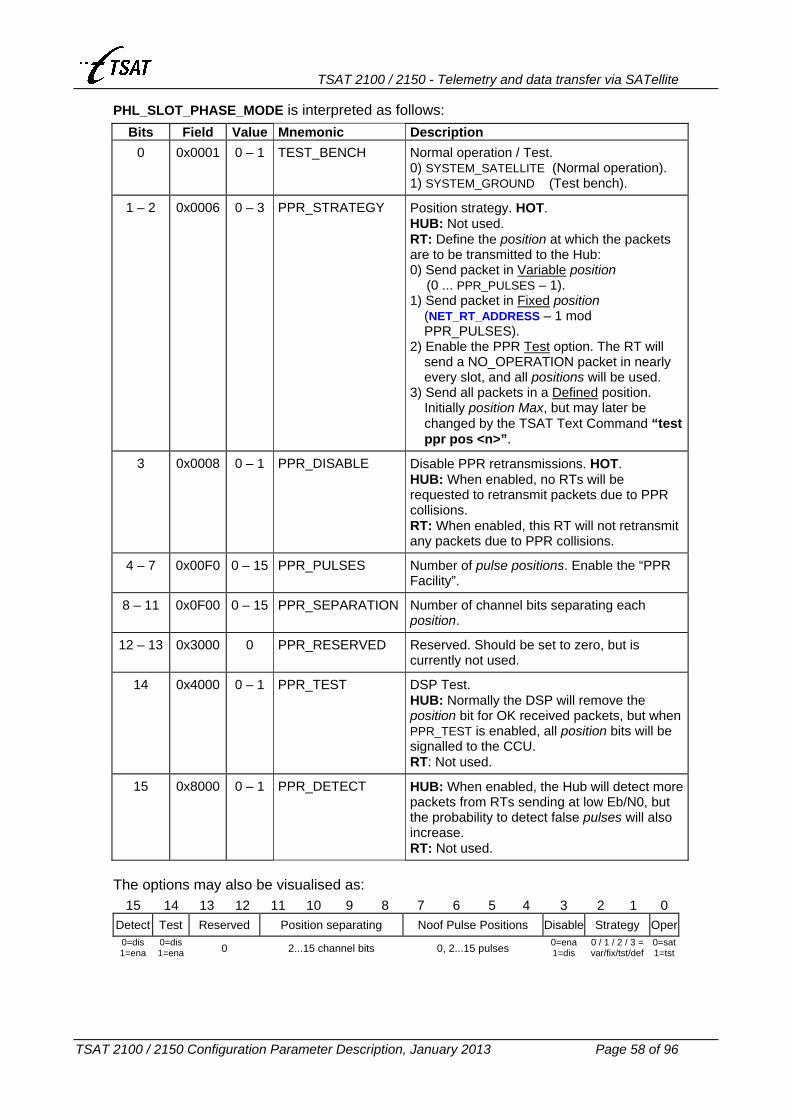
TSAT 2100 / 2150 - Telemetry and data transfer via SATellite
TSAT 2100 / 2150 Configuration Parameter Description, January 2013 Page 58 of 96
PHL_SLOT_PHASE_MODE is interpreted as follows:
Bits Field Value Mnemonic Description 0 0x0001 0 – 1 TEST_BENCH Normal operation / Test.
0) SYSTEM_SATELLITE (Normal operation). 1) SYSTEM_GROUND (Test bench).
1 – 2 0x0006 0 – 3 PPR_STRATEGY Position strategy. HOT. HUB: Not used. RT: Define the position at which the packets are to be transmitted to the Hub: 0) Send packet in Variable position
(0 ... PPR_PULSES – 1). 1) Send packet in Fixed position
(NET_RT_ADDRESS – 1 mod PPR_PULSES).
2) Enable the PPR Test option. The RT will send a NO_OPERATION packet in nearly every slot, and all positions will be used.
3) Send all packets in a Defined position. Initially position Max, but may later be changed by the TSAT Text Command “test ppr pos <n>”.
3 0x0008 0 – 1 PPR_DISABLE Disable PPR retransmissions. HOT. HUB: When enabled, no RTs will be requested to retransmit packets due to PPR collisions. RT: When enabled, this RT will not retransmit any packets due to PPR collisions.
4 – 7 0x00F0 0 – 15 PPR_PULSES Number of pulse positions. Enable the “PPR Facility”.
8 – 11 0x0F00 0 – 15 PPR_SEPARATION Number of channel bits separating each position.
12 – 13 0x3000 0 PPR_RESERVED Reserved. Should be set to zero, but is currently not used.
14 0x4000 0 – 1 PPR_TEST DSP Test. HUB: Normally the DSP will remove the position bit for OK received packets, but when PPR_TEST is enabled, all position bits will be signalled to the CCU. RT: Not used.
15 0x8000 0 – 1 PPR_DETECT HUB: When enabled, the Hub will detect more packets from RTs sending at low Eb/N0, but the probability to detect false pulses will also increase. RT: Not used.
The options may also be visualised as:
15 14 13 12 11 10 9 8 7 6 5 4 3 2 1 0 Detect Test Reserved Position separating Noof Pulse Positions Disable Strategy Oper
0=dis 1=ena
0=dis 1=ena 0 2...15 channel bits 0, 2...15 pulses 0=ena
1=dis 0 / 1 / 2 / 3 = var/fix/tst/def
0=sat1=tst

TSAT 2100 / 2150 - Telemetry and data transfer via SATellite
TSAT 2100 / 2150 Configuration Parameter Description, January 2013 Page 59 of 96
3.6.4 PHL_SLOT_PHASE_SETPOINT -- SLOTPHASE_SETPOINT Ver <= 22.5.0 Default 0, Range (–32768...+32768) Ver == 22.6.0 Default 0, Range (–32768...+32768) – HOT Ver >= 22.7.0 Default –50, Range –10000...+10000 – HOT
The MIB parameter is expressed in 1/10 millisecond units.
HUB: Not Used.
RT: It has no effect to set PHL_SLOT_PHASE_SETPOINT if the system is configured to test modus (see PHL_SLOT_PHASE_MODE).
Note: The MIB parameter is called SLOTPHASE_SETPOINT in Ver <= 22.2.3 The Slot Phase Set Point is used to specify the time at which the DSP shall start the transmission of a slot. It is required to set this variable on the RTs so that the Hub will receive the packets from all RTs at exactly the same point of time, independent of the RT’s geographical location (i.e. satellite delay). Ver >= 22.6.0
The Slot Phase Setpoint Auto-Correction facility is implemented by the following procedure: The UW position (the point of time when the Hub receives the packet) of all Slot-Zero packets (normally POLL_ACK) is reported back to the RT in the next SYNC packet. The RT will use this information to correct its own Slot Phase Setpoint, to match the networks target UW position. Setting bit 15 (0x0.8000) in UTL_UTILITY_MASK will disable this facility. Setting bit 16 (0x1.0000) in UTL_UTILITY_MASK will enable the Scanning facility. The RT will try with different Slot Phase Set Point values when it is sending LINK_RESET to the Hub. Note that the UW position received from the Hub DSP is measured in: • DSP Ver <= P22.2.2: Number of Link-bit-rate bits. • DSP Ver >= P22.3.0: Number of 1/38400 seconds. ...while the UW position reported back to the RTs is measured in: • Number of 1/38400 seconds.
As already mentioned, the PHL_SLOT_PHASE_SETPOINT is expressed in 1/10 milliseconds units. This value is converted by the CCU, and the actual value that is sent to the DSP is expressed in: • DSP Ver <= P22.2.2: Number of 1/10000 second units. • DSP Ver >= P22.3.0: Number of 1/38400 second units. Ver == 22.6.0 … 24.4.7
The operator may bypass the CCU conversion by prefixing the value with 0xABCD when he is changing the CURRENT MIB variable. Examples: The value 0xABCD0009 is giving the following results:
DSP Ver <= P22.2.2: 9/10000 = 0.90 millisec. DSP Ver >= P22.3.0: 9/38400 = 0.23 millisec.
Note: CCU versions <= C22.5.0 cannot be used together with DSP versions >= P22.3.0.

TSAT 2100 / 2150 - Telemetry and data transfer via SATellite
TSAT 2100 / 2150 Configuration Parameter Description, January 2013 Page 60 of 96
3.6.5 PHL_INBOUND_IDENTITY Ver <= 24.4.7 Default 40, Range (0...65536) Ver >= 25.0.0 Default 850, Range 0...65536 ‘
Carrier identifier for inbound carrier (related to the Hub), PHL_TX_RT_FREQUENCY. This identifier must be set alike for the Hub and all RTs using the same carrier. It is used to prohibit the Hub to lock to a carrier of another TSAT system with frequencies within its search range. The identifier must be in the range 0 to 65535.
Note: It’s a requirement that PHL_INBOUND_IDENTITY is different to PHL_OUTBOUND_IDENTITY when DSP is version >= P22.5.7, and PHL_SLOT_PHASE_MODE > 0 (i.e. PPR is enabled).
3.6.6 PHL_INBOUND_IDENTITY_2 Ver <= 24.4.7 Default 0, Range (0...65536) Ver >= 25.0.0 Default 0, Range 0...65536
Carrier identifier for the secondary inbound carrier (related to the Slave Hub), PHL_TX_RT_FREQUENCY_2. This identifier must be set alike for the Slave Hub and all RTs using the same secondary carrier. It is used to prohibit the Slave Hub to lock to a carrier of another TSAT system with frequencies within its search range. The identifier must be in the range 0 to 65535.
3.6.7 PHL_INBOUND_IDENTITY_BKUP Ver <= 24.4.7 Default 0, Range (0...65536) – NoCurrent Ver >= 25.0.0 Default 0, Range 0...65536 – NoCurrent
Ver <= 22.2.4 Not Implemented.
Ver == 22.2.5 ... 22.2.6 Not Used.
Ver >= 22.3.0
HUB: Not Used. RT: Carrier identifier for the inbound carrier PHL_TX_RT_FREQUENCY_BKUP to the Backup
Hub.
3.6.8 PHL_INBOUND_IDENTITY_2_BKUP Ver <= 24.4.7 Default 0, Range (0...65536) – NoCurrent Ver >= 25.0.0 Default 0, Range 0...65536 – NoCurrent
Ver <= 22.2.4 Not Implemented.
Ver == 22.2.5 ... 22.2.6 Not Used.
Ver >= 22.3.0
HUB: Not Used. RT: Carrier identifier for the secondary inbound carrier PHL_TX_RT_FREQUENCY_2_BKUP to
the Backup Hub.

TSAT 2100 / 2150 - Telemetry and data transfer via SATellite
TSAT 2100 / 2150 Configuration Parameter Description, January 2013 Page 61 of 96
3.6.9 PHL_OUTBOUND_IDENTITY Ver <= 24.4.7 Default 0, Range (0...65536) Ver >= 25.0.0 Default 875, Range 0...65536
Carrier identifier for outbound carrier (related to the Hub), PHL_TX_HUB_FREQUENCY. This identifier must be set alike for the Hub and all RTs using the same carrier. It is used to prohibit the RT to lock to a carrier of another TSAT system with frequencies within its search range. The identifier must be in the range 0 to 65535.
Note: It’s a requirement that PHL_INBOUND_IDENTITY is different to PHL_OUTBOUND_IDENTITY when DSP is version >= P22.5.7, and PHL_SLOT_PHASE_MODE > 0 (i.e. PPR is enabled).
3.6.10 PHL_OUTBOUND_IDENTITY_BKUP Ver <= 24.4.7 Default 0, Range (0...65536) – NoCurrent Ver >= 25.0.0 Default 0, Range 0...65536 – NoCurrent
Ver <= 22.2.4 Not Implemented.
Ver == 22.2.5 ... 22.2.6 Not Used.
Ver >= 22.3.0
HUB: Not Used. RT: Carrier identifier for the outbound carrier PHL_TX_HUB_FREQUENCY_BKUP from the
Backup Hub.

TSAT 2100 / 2150 - Telemetry and data transfer via SATellite
TSAT 2100 / 2150 Configuration Parameter Description, January 2013 Page 62 of 96
3.6.11 PHL_TX_HUB_FREQUENCY Ver <= 24.4.7 Default 14.455.000, Range (0 + 14.000.000...14.500.000) Ver >= 25.0.0 Default 14.239.875, Range 14.000.000...14.500.000
The Hub TX frequency in kHz. Range from 14.000.000 to 14.500.000. Transmission from Hub will be disabled if this variable is set to 0 (Ver <= 24.4.7).
3.6.12 PHL_TX_RT_FREQUENCY Ver <= 24.4.7 Default 14.455.040, Range (0 + 14.000.000...14.500.000) Ver >= 25.0.0 Default 14.239.850, Range 14.000.000...14.500.000
The RT TX frequency in kHz. Range from 14.000.000 to 14.500.000. Transmission from RT will be disabled if this variable is set to 0 (Ver <= 24.4.7).
3.6.13 PHL_TX_RT_FREQUENCY_2 Ver <= 24.4.7 Default 0, Range (0 + 14.000.000...14.500.000) Ver >= 25.0.0 Default 0, Range 0 + 14.000.000...14.500.000
The RT secondary TX frequency in kHz. Range from 14.000.000 to 14.500.000. A legal value will define the Main Unit as a RT or Slave Hub (i.e. Hub transmission will be disabled) in a multi inbound carrier system. This frequency is used for RT to Slave Hub communication, while PHL_TX_RT_FREQUENCY is used for RT to Master Hub communication. Note: See also PHL_BITRATE_MODE.

TSAT 2100 / 2150 - Telemetry and data transfer via SATellite
TSAT 2100 / 2150 Configuration Parameter Description, January 2013 Page 63 of 96
3.6.14 PHL_TX_HUB_FREQUENCY_BKUP Ver <= 24.4.7 Default 0, Range (0 + 14.000.000...14.500.000) – NoCurrent Ver >= 25.0.0 Default 0, Range 0 + 14.000.000...14.500.000 – NoCurrent
Ver <= 22.2.4 Not Implemented.
Ver == 22.2.5 ... 22.2.6
Not Used. Ver >= 22.3.0
HUB: Not Used. RT: The Backup Hub TX frequency in kHz. The RT will switch to receive from this Hub if it
cannot achieve carrier lock to the Main Hub. See also NET_MAX_POLL_PACKETS. Setting this MIB variable to zero disables this functionality.
3.6.15 PHL_TX_RT_FREQUENCY_BKUP Ver <= 24.4.7 Default 0, Range (0 + 14.000.000...14.500.000) – NoCurrent Ver >= 25.0.0 Default 0, Range 0 + 14.000.000...14.500.000 – NoCurrent
Ver <= 22.2.4 Not Implemented.
Ver == 22.2.5 ... 22.2.6
Not Used. Ver >= 22.3.0
HUB: Not Used. RT: The RT TX frequency to Backup Hub in kHz. Setting PHL_TX_HUB_FREQUENCY_BKUP
to zero disables the Backup Hub functionality.
3.6.16 PHL_TX_RT_FREQUENCY_2_BKUP Ver <= 24.4.7 Default 0, Range (0 + 14.000.000...14.500.000) – NoCurrent Ver >= 25.0.0 Default 0, Range 0 + 14.000.000...14.500.000 – NoCurrent
Ver <= 22.2.4 Not Implemented.
Ver == 22.2.5 ... 22.2.6
Not Used. Ver >= 22.3.0
HUB: Not Used. RT: The RT TX frequency to Backup Slave Hub in kHz. Setting
PHL_TX_HUB_FREQUENCY_BKUP to zero disables the Backup Hub functionality. Setting this MIB variable to zero disables the Backup Slave Hub functionality. See also PHL_TX_RT_FREQUENCY_2.

TSAT 2100 / 2150 - Telemetry and data transfer via SATellite
TSAT 2100 / 2150 Configuration Parameter Description, January 2013 Page 64 of 96
3.6.17 PHL_TX_FREQUENCY_ADJUST Ver <= 24.4.7 Default 0, Range (–32768...+32768) – HOT Ver >= 25.0.0 Default 0, Range –10000...+10000 – HOT
The inbound carrier from RTs with different hardware revisions (TSAT 2100 (HW-Id < 16) and TSAT 2150 (HW-Id >= 16)), and different DSP software versions (version <= P22.4.0, and version >= 22.5.0) are received by the Hub at slightly different frequencies. Up to 150 Hz difference has been observed.
This doesn’t cause any problems in a homogeneous network with only TSAT 2100 or TSAT 2150 RTs (and all RT DSPs are version <= P22.4.0 or version >= P22.5.0). However, in a mixed network with both older and newer hardware and/or older and newer DSP software, the RTs will send at different frequencies, and the HUB will have problems to receive all RTs. Therefore, we have to slightly adjust the RT’s transmitting frequency. Ver <= 24.0.0
Not Implemented. Ver >= 24.1.0
HUB: It’s possible to adjust the Hub’s outbound frequency, but why should you do this?
RT: PHL_TX_FREQUENCY_ADJUST (expressed in Hz) is used to adjust the RT’s inbound frequency.
You might enable Automatic Frequency Adjustment (AFA), by setting bit 23 (0x80.0000 – UTILITY_TX_FREQUENCY_ADJUST) in UTL_UTILITY_MASK. Do not confuse with Absolute Frequency Control (AFC). Note: You should NOT enable AFA, when the HUB is Ver <= 25.0.0. HUB version must be
>= 25.0.1.
Enable AFA will only have effect on RTs with CCU version >= C24.1.0 and DSP version >= P22.5.0. When enabled, AFA works as follows: • The RT’s DSP software version is signalled from RT to HUB in all POLL_ACK packets.
When RT Ver >= 25.0.0, the RT’s HW revision (i.e. TSAT 2100 or 2150) is also signalled from RT to HUB in all POLL_ACK packets.
• The HUB (Ver >= 25.0.0) will select one of the RTs as reference frequency, and keep this RT as Reference-RT until link has been reported DOWN (for more than 10 poll-cycles), or a more prioritised RT is reported UP (i.e. is included in the poll-cycle for more than 10 poll-cycles). The HUB is selecting the Reference-RT after the following criteria: 1) Preferable the first RT in the poll-cycle with CCU version <= C24.0.0 or DSP version
<= P22.4.0 is selected (because such RTs cannot adjust frequency). 2) The first RT in the poll-cycle with CCU version <= C24.4.7 or HW revision <= 15 (i.e.
TSAT 2100, but only RTs Ver >= 25.0.0 are telling the HUB whether they are TSAT 2100 or 2150).
3) The first RT in the poll-cycle. • The offset frequency (compared to the other RTs inbound frequency) is signalled to
each of the RTs (but not the Reference-RT) in the SYNC packets. Only RTs with CCU >= C24.1.0 and DSP >= P22.5.0 are requested to modify their TX frequency.
• Only RTs with AFA enabled, will actually adjust their TX frequency. The CURRENT value of PHL_TX_FREQUENCY_ADJUST will be modified (in small steps). However, it cannot be automatically adjusted to a value outside the range (EEPROM value of PHL_TX_FREQUENCY_ADJUST) +/– 150 Hz.

TSAT 2100 / 2150 - Telemetry and data transfer via SATellite
TSAT 2100 / 2150 Configuration Parameter Description, January 2013 Page 65 of 96
RT Ver == 25.0.0 … 25.1.2: If the RT isn’t able to Open the link to HUB (i.e. it has sent
LINK_RESET to HUB a number of times (LCC_MAX_LINK_RETRIES – default 5), without any reply), it would normally RESET itself. When AFA is enabled, the following procedure apply: • Adjust the TX freq. in 25 Hz steps, and send more LINK_RESET packets to the HUB. • Try all frequencies in the range PHL_TX_RT_FREQUENCY +
PHL_TX_FREQUENCY_ADJUST +/– 200 Hz. • The RT will RESET itself, if no connection is achieved after several (85) retries. • When connection is achieved, the RT will save the CURRENT (i.e. modified) value of
PHL_TX_FREQUENCY_ADJUST to EEPROM, and then FLUSH it.
RT Ver >= 25.1.3: The “RT Frequency Scanning” facility (as described above) is disabled. 3.6.18 PHL_TX_FREQUENCY_ADJUST_2
Ver <= 24.4.7 Default 0, Range (–32768...+32768) – HOT Ver >= 25.0.0 Default 0, Range –10000...+10000 – HOT
Ver <= 24.4.6 Not Implemented.
Ver >= 24.4.7
HUB: Not used.
RT: The parameter has the same meaning and interpretation as PHL_TX_FREQUENCY_ADJUS, but this value is used on the Secondary Inbound carrier (MIL network).
3.6.19 PHL_TX_FREQUENCY_ADJUST_BKUP
Ver <= 24.4.7 Default 0, Range (–32768...+32768) – NoCurrent Ver >= 25.0.0 Default 0, Range –10000...+10000 – NoCurrent
Ver <= 24.4.1 Not Implemented.
Ver >= 24.4.2
HUB: Not used.
RT: The parameter has the same meaning and interpretation as PHL_TX_FREQUENCY_ADJUS, but this value is used when the Backup set of frequencies is used.
3.6.20 PHL_TX_FREQUENCY_ADJUST_2_BKUP
Ver <= 24.4.7 Default 0, Range (–32768...+32768) – NoCurrent Ver >= 25.0.0 Default 0, Range –10000...+10000 – NoCurrent
Ver <= 24.4.6 Not Implemented.
Ver >= 24.4.7
HUB: Not used.
RT: The parameter has the same meaning and interpretation as PHL_TX_FREQUENCY_ADJUS, but this value is used on the Secondary Inbound carrier (MIL network) when the Backup set of frequencies is used.

TSAT 2100 / 2150 - Telemetry and data transfer via SATellite
TSAT 2100 / 2150 Configuration Parameter Description, January 2013 Page 66 of 96
3.6.21 PHL_SWITCH_BACK_TO_MAIN_HUB
Default 0, Range –1...1440 – HOT
The “Auto RT Switch-Back to Main Hub” function is controlled by an option in NMS ‘Network Behaviour’ window. This parameter controls the RT behaviour when this option is enabled. Ver <= 25.1.8
Not Implemented. Ver >= 25.2.0
HUB: Not used.
RT: Used when Backup-Hub is defined (i.e. PHL_TX_HUB_FREQUENCY_BKUP > 0) and “Auto RT Switch-Back to Main Hub” option is enabled in NMS:
Value Interpretation -1 Disable “Auto Switch-Back to Main Hub” at this RT 0 Immediately Switch-Back to Main Hub when it’s reported operational.
1 – 1440
Wait specified number of minutes (after first Link Open to Backup-Hub) before doing a Switch-Back to Main-Hub.

TSAT 2100 / 2150 - Telemetry and data transfer via SATellite
TSAT 2100 / 2150 Configuration Parameter Description, January 2013 Page 67 of 96
3.6.22 PHL_DELTA_SEARCH_FREQUENCY -- DELTA_SEARCH_FREQUENCY Ver <= 22.2.4 Default 30, Range (5...500) Ver == 22.2.5 … 24.2.3 Default 60, Range (5...500) Ver == 24.2.4 … 24.4.7 Default 60, Range (0x0...0x007F.FFFF) Ver >= 25.0.0 Default 60, Range 10...0x007F.FFFF
Ver <= 24.2.3 Half the frequency search range, expressed in kHz.
Ver >= 24.2.4
Bit Field Value Interpretation 0 - 7 0x0000.00FF 0 - 255 Half the frequency search range when CCU is reading
Spectrum from DSP (kHz) – as before.
8 - 22 0x007F.FF00 0 - 32767 When enabled (greater than zero), the default frequency search range (when CCU is searching for Hub/RT) is overridden (Hz). HOT. HUB: Default is normally 300 Hz, but 500 Hz when bit 22
(0x40.0000 – UTILITY_RT_HUB_FREQ_ERROR) in UTL_UTILITY_MASK is enabled. When HUB is searching for HUB: +/– SearchRange. When HUB is searching for RT: +/– 2 x SearchRange
RT: Default is always 300 Hz. When RT is searching for HUB: +/– SearchRange.
It’s also possible to set SearchRange by the TSAT Text Command “search <SearchRange>”.
23 - 31 0xFF80.0000 0 - 511 Not used.
Calculate the MIB value as: SearchRange[Hz] * 256 + DeltaSearchFrequency[kHz]
Note: The MIB parameter is called DELTA_SEARCH_FREQUENCY in Ver <= 24.4.7.
3.6.23 PHL_SAT_CONVERT_FREQUENCY -- SAT_CONVERT_FREQUENCY
Ver <= 24.4.7 Default 1.500.000, Range (1.000.000...10.000.000) Ver >= 25.0.0 Default 1.500.000, Range 500.000... 5.000.000
The satellite conversion frequency in kHz. Typically 1.500.000 or 2.800.000. Note: The MIB parameter is called SAT_CONVERT_FREQUENCY in Ver <= 24.4.7.

TSAT 2100 / 2150 - Telemetry and data transfer via SATellite
TSAT 2100 / 2150 Configuration Parameter Description, January 2013 Page 68 of 96
3.6.24 PHL_FE_{RX | TX}_LO -- FE_{RX | TX}_LO Ver <= 23.3.1 RX: Default 11.250.000, Range (defined by LNB) TX: Default 13.250.000, Range (defined by BUC) Ver == 23.4.0 … 24.4.7 RX+TX: Default 1554, Range (defined by LNB+BUC) Ver >= 25.0.0 RX+TX: Default 1602, Range (defined by LNB+BUC)
Sets the lower RX and TX frequencies (kHz) in the Front End. The MIB values must match the connected Front End. Ver >= 23.4.0
You can still program PHL_FE{RX | TX}_LO with the Front-End’s local oscillator frequencies, but it’s now also possible to program them with SET values. The CCU will replace (EEPROM) SET values with (CURRENT) real frequencies, as shown in the table below:
SET value Front End PHL_FE_TX_LO [kHz]
PHL_FE_RX_LO [kHz]
1552 RFA 1552 (TSAT) 13.260.000 10.455.000 1554 RFA 1554 (TSAT) 13.260.000 11.220.000 1555 RFA 1555 (TSAT) 13.515.000 11.220.000 1602 RFA 1602 (ZINWELL) 13.050.000 11.300.000 1603 RFA 1603 (ZIN+NOR) 15.450.000 11.300.000 1604 RFA 1604 (NORSAT) 15.450.000 11.300.000 1605 RFA 1605 (NOR+ZIN) 13.050.000 11.300.000
Note: The MIB parameters are called FE_{RX | TX}_LO in Ver <= 24.4.7.
Note: Currently, the following BUC and LNBs are used with TSAT 2150 Main Units.
Type TSAT Part No PHL_FE_TX_LO [kHz] PHL_FE_RX_LO [kHz]
BUC TX 1414 13.050.000 n/a LNB RX 1410 A n/a 11.300.000 LNB RX 1410 B n/a 10.000.000 LNB RX 1410 C n/a 10.750.000
3.6.25 {MOD | DEMOD}_NCO_NOM MOD HwId = 0 Default 4.530.000, Range 4.000.000.....5.000.000 DEMOD HwId = 0 Default 4.470.000, Range 4.000.000.....5.000.000 MOD HwId > 0 Default 10.730.000, Range 10.000.000...20.000.000 DEMOD HwId > 0 Default 10.670.000, Range 10.000.000...20.000.000
Ver <= 24.4.7 Not used. Defines the hardware dependent reference frequency in Hz.
SYS_HW_REVISION Reference frequency
0 4.5 MHz
>= 1 10.7 MHz
Ver >= 25.0.0 Not Implemented. Default values are hard-coded.

TSAT 2100 / 2150 - Telemetry and data transfer via SATellite
TSAT 2100 / 2150 Configuration Parameter Description, January 2013 Page 69 of 96
3.7 PACKET PARAMETERS 3.7.1 PKT_MAX_SIZE
Ver <= 22.2.4 Default 180, Range 8...255 Ver == 22.5.0 ... 22.7.1 Default 180, Range 50...255 Ver >= 22.8.0 Default 255, Range 50...255
Sets the size of the CCU’s internal packet structure, and must be in the range from 50 to 255 bytes. The actual link layer packet size is set by PKT_OUTBOUND_SIZE.
Ver <= 22.4.0 254 bytes >= PKT_MAX_SIZE >= PKT_OUTBOUND_SIZE + 24 bytes
Ver >= 22.5.0 255 bytes >= PKT_MAX_SIZE >= PKT_OUTBOUND_SIZE + 22 bytes
In TSAT networks equipped with X.25, PKT_MAX_SIZE must be greater or equal 98 bytes, due to the maximum X.25 Management message (get all active SVC's).
3.7.2 PKT_OUTBOUND_SIZE Ver <= 22.7.1 Default 150, Range (60...233) Ver == 22.8.0 … 24.4.7 Default 60, Range (40...233) Ver >= 25.0.0 Default 60, Range 30...233
Sets the number of bytes in a satellite link packet from Hub to RT. It should at least be greater or equal 30 bytes, due to the size of SYNC packets.
Ver <= 22.4.0 The size selected must at least be 2+3+17+2=24 bytes less than PKT_MAX_SIZE.
Ver >= 22.5.0 The size selected must at least be 2+3+17=22 bytes less than PKT_MAX_SIZE.
Note: When FEC = 3/4 or 7/8 (see PHL_BITRATE_MODE), the value of PKT_OUTBOUND_SIZE is
restricted to: • When FEC = 3/4: PKT_OUTBOUND_SIZE modulo 3 must be 0. • When FEC = 7/8: PKT_OUTBOUND_SIZE modulo 7 must be 0 or 2.

TSAT 2100 / 2150 - Telemetry and data transfer via SATellite
TSAT 2100 / 2150 Configuration Parameter Description, January 2013 Page 70 of 96
3.7.3 PKT_INBOUND_SIZE Read-Only
Read the number of bytes in a satellite link packet from RT to Hub. It is calculated after the restart of the Main Unit. PKT_INBOUND_SIZE should at least be greater or equal 29 bytes, due to the size of RT_STATISTICS packets (when the Supervisory Terminal is requesting statistics from the RTs). The following values are used:
User Link Bit Rate PKT_INBOUND_SIZE
4800 bps = PKT_OUTBOUND_SIZE – 1 byte. 7200 bps = PKT_OUTBOUND_SIZE – 1 byte. 8400 bps = PKT_OUTBOUND_SIZE – 2 bytes. 9600 bps = PKT_OUTBOUND_SIZE – 2 bytes. 14400 bps = PKT_OUTBOUND_SIZE – 2 bytes. 16800 bps = PKT_OUTBOUND_SIZE – 3 bytes.
Ver >= 22.7.0
The PKT_INBOUND_SIZE will be further decreased when the “Pulse Position Reservation (PPR) Facility” is enabled. See PHL_SLOT_PHASE_MODE.
3.7.4 PKT_POOL_SIZE -- PKT_NO_OF_MEDIUM_PKTS Ver <= 22.6.0 Default 100, Range 20... 300 Ver == 22.7.0 … 23.0.1 Default 150, Range 20...1000 Ver == 23.1.0 … 24.4.7 Default 300, Range 20...1000 Ver >= 25.0.0 Default 300, Range 100...1000
Sets the number of available packets in the CCU. It may cause loss of data if set too small. Note: The MIB parameters are called PKT_NO_OF_MEDIUM_PKTS in Ver <= 24.4.7.

TSAT 2100 / 2150 - Telemetry and data transfer via SATellite
TSAT 2100 / 2150 Configuration Parameter Description, January 2013 Page 71 of 96
3.8 POWER PARAMETERS 3.8.1 POW_WAKEUP_FIRST_TIME
Default 0, Range –1...1440 – HOT
Controls the Main Unit power-save (sleep) functions:
Ver <= 22.3.1 Not implemented.
Ver >= 22.4.0
This MIB variable is only used when the Main Unit power-save (controlled by CCU at regular intervals) function is enabled: 0 < POW_LINK_UP_DURATION < POW_WAKEUP_INTERVAL. To let the different RTs wake up to specified time(s) (relative to Supervisory Terminal, Hub and RT Real Time), the MIB variable should be different to zero. Examples:
POW_WAKEUP_ FIRST_TIME
POW_WAKEUP_INTERVAL
CCU is waking UP (hh:mm)
12 60 00:12, 01:12, 02:12, … 23:12
10 10 00:00, 00:10, 00:20, … 23:50
1 70 00:01, 01:11, 02:21, … 23:21
On the RTs, POW_WAKEUP_FIRST_TIME may be set to –1, in which case all RTs will wake up to different times, specified by:
(POW_WAKEUP_INTERVAL x NET_RT_ADDRESS) / NET_NO_OF_RTS.
3.8.2 POW_LINK_UP_DURATION Default 0, Range 0...1440 – HOT
Controls the Main Unit power-save (sleep) functions:
Ver <= 22.3.1 Not implemented.
Ver >= 22.4.0
Used together with POW_WAKEUP_INTERVAL to enable the power-save (controlled by CCU at regular intervals) function. Range is 1 … 1440 minutes, i.e. 1 minute … 1 day.

TSAT 2100 / 2150 - Telemetry and data transfer via SATellite
TSAT 2100 / 2150 Configuration Parameter Description, January 2013 Page 72 of 96
3.8.3 POW_WAKEUP_INTERVAL Default 0, Range 0...10080 – HOT
Controls the Main Unit power-save (sleep) functions:
Ver <= 22.3.1 Not implemented.
Ver >= 22.4.0
The Main Unit power-save function (controlled by connected Application) is enabled if POW_WAKEUP_INTERVAL is greater than zero, and COM{n}_CD_IN_FUNC is 1. The Main Unit power-save function (controlled by CCU at regular intervals) is enabled if the following equation is true: 0 < POW_LINK_UP_DURATION < POW_WAKEUP_INTERVAL. The power-save functions are somewhat different implemented on Hub and RT, but both units will wake up (turn power ON) every POW_WAKEUP_INTERVAL minute (range 2 …10080: i.e. 2 minutes … 1 week). HUB: Wait until the power has been ON for POW_LINK_UP_DURATION minutes, then it will
turn power OFF, and go to sleep for (POW_WAKEUP_INTERVAL – POW_LINK_UP_DURATION) minutes.
RT: Wait until the link to Hub has been UP for POW_LINK_UP_DURATION +/– 0.5 minutes, then a LINK_DISCONNECT message will be sent to the Hub, it will wait 3 seconds, program the power to be turned ON after a calculated number of minutes (remaining minutes until next wake up), and turn the power OFF. Se also POW_WAKEUP_FIRST_TIME.
Note 1: Strap SW902 must be connected to enable the power down functions. Note 2: The power will be turned ON when the CD signal is changing from OFF to ON, or
after the programmed number of minutes has elapsed, whichever occurs first. Note 3: The CD input signal has to be either terminated or un-connected. By no way it should
be connected to a cable, and not terminated in the other end.

TSAT 2100 / 2150 - Telemetry and data transfer via SATellite
TSAT 2100 / 2150 Configuration Parameter Description, January 2013 Page 73 of 96
3.8.4 POW_LISTEN_HPA_ON Ver <= 24.4.7 Default 0, Range (0...255) – HOT Ver >= 25.0.0 Default 0, Range 0...255 – HOT
Controls the RT Main Unit power-save (listen) mode:
Ver <= 23.3.1 Not implemented.
Ver >= 23.4.0
HUB: Not used. RT: The RT is normally consuming 35 W, but only 20 W when HPA is disabled. You can
enable this power-save (listen) mode by setting POW_LISTEN_HPA_ON >= 1. When enabled, the operation is as follows: • The HPA is normally OFF, but when the RT has something to send to the HUB, it will
turn HPA ON, wait POW_LISTEN_HPA_ON ∗ 10 millisec, and then send the packet(s). A value of 60 (i.e. 600 ms) seems to function OK (due to the long HPA settle time).
• When the RT doesn’t have more packets to send, it will wait POW_LISTEN_HPA_OFF ∗ 10 millisec, and then turn HPA OFF again. A value of 0 (i.e. immediately) is functioning OK. If you expect more data from the connected Application a short time after the first batch of packet(s) have been sent, it might be a good idea to increase POW_LISTEN_HPA_OFF.
Note 1: The polled round-trip delay will increase with POW_LISTEN_HPA_ON ∗ 10 millisec (normally 600 ms) when this power-save mode is enabled.
Note 2: All RTs operating in Power-Save (listen) mode, should also use the timeout-polling scheme. See POW_LISTEN_POLL
Note 3: Calculating the exact amount of consumed power, is a function of: • HPA turn-on time (approx. 500 – 550 ms) • HPA turn-off time (approx. 1300 – 1500 ms). • Slots in Frame – MAC_TIMESLOTS_IN_FRAME. • Slot Access Schemes – MAC_TIMESLOT_MAP_{n}. • Slot Length – MAC_TIMESLOT_LENGTH. • Number of returned Application packets. • The frequency at which the Application is polled. • POW_LISTEN_HPA_ON + POW_LISTEN_HPA_OFF. • POW_LISTEN_POLL. To make it simple: Assume that the RT is using 35 W @ 3 seconds each time the RT or Application is polled, and that it’s using 20 W in the time between polls.
3.8.5 POW_LISTEN_HPA_OFF Ver <= 24.4.7 Default 0, Range (0...255) – HOT Ver >= 25.0.0 Default 0, Range 0...255 – HOT
Controls the RT Main Unit power-save (listen) mode:
Ver <= 23.3.1 Not implemented.
Ver >= 23.4.0
HUB: Not used. RT: Used together with POW_LISTEN_HPA_ON to control the RT’s power-save (listen) mode.

TSAT 2100 / 2150 - Telemetry and data transfer via SATellite
TSAT 2100 / 2150 Configuration Parameter Description, January 2013 Page 74 of 96
3.8.6 POW_LISTEN_POLL Ver <= 24.4.7 Default 0, Range (0...255) – HOT Ver >= 25.0.0 Default 0, Range 0...255 – HOT
Controls the RT Main Unit power-save (listen) mode:
Ver <= 23.3.1 Not implemented.
Ver >= 23.4.0
During the exchange of LINK_RESET / LINK_ACK messages, the RT will request the HUB to be included or excluded from the regular polling of all RTs. Two polling schemes are implemented: A) Regular (traditional) Polling: The HUB will include a request for POLL_ACK packet from
RTs in each SYNC packet. The RTs are polled one after each other (1, 2, 3, … NET_NO_OF_RTS, 1, 2, 3, …).
B) Timeout Polling: The HUB will send a POLL packet to the RTs at regular (configurable) intervals, and expect a reply (POLL_ACK) within 3 seconds. The link is reported DOWN, when no reply has been returned after 3 re-transmissions. A minimum delay of 5 seconds is included between each issued POLL packet.
HUB: This parameter is only used when one or more of the RTs also have
POW_LISTEN_POLL > zero. In this case, the total time between two POLLs to this RT is defined by: POW_LISTEN_POLL (HUB side) ∗ POLL_LISTEN_POLL (RT side) seconds. Normally, POW_LISTEN_POLL (at HUB) should be 60, so that the denomination of POW_LISTEN_POLL (at RT) can be given in minutes.
Value Description 0 NOT valid. Will always be replaced by value 60 (i.e. 1 minute).
1 – 255 Send POLL packets to RTs included in the timeout-polling scheme each (HUB) POW_LISTEN_POLL x (RT) POLL_LISTEN_POLL seconds.
RT: Include or exclude this RT from the regular-polling scheme.
Value Description 0 Include this RT in the regular-(traditional) polling scheme.
1 – 254 Exclude this RT from the regular-polling scheme, and request the HUB to send a POLL packet to this RT each (HUB) POW_LISTEN_POLL x (RT) POLL_LISTEN_POLL sec.
255 Exclude this RT from both the regular- and timeout-polling schemes.
Note 1: All RTs operating in Power-Save (listen) mode should always be excluded from the regular-polling scheme. However, normal RTs may also use the timeout-polling scheme.
Note 2: At least one RT in the network should always be included in the regular-polling scheme.
Note 3: RTs in a Multi-Inbound Link (MIL) network cannot be excluded from the regular-polling scheme.
Note 4: The HUB will not detect when the link is DOWN, when the RT is excluded from both the regular- and timeout-polling schemes,
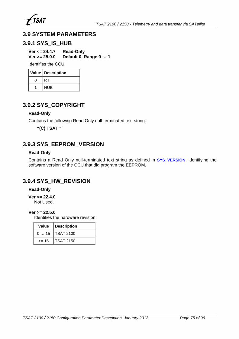
TSAT 2100 / 2150 - Telemetry and data transfer via SATellite
TSAT 2100 / 2150 Configuration Parameter Description, January 2013 Page 75 of 96
3.9 SYSTEM PARAMETERS 3.9.1 SYS_IS_HUB
Ver <= 24.4.7 Read-Only Ver >= 25.0.0 Default 0, Range 0 … 1
Identifies the CCU.
Value Description
0 RT
1 HUB
3.9.2 SYS_COPYRIGHT Read-Only
Contains the following Read Only null-terminated text string:
“(C) TSAT “
3.9.3 SYS_EEPROM_VERSION Read-Only
Contains a Read Only null-terminated text string as defined in SYS_VERSION, identifying the software version of the CCU that did program the EEPROM.
3.9.4 SYS_HW_REVISION Read-Only
Ver <= 22.4.0 Not Used.
Ver >= 22.5.0
Identifies the hardware revision.
Value Description
0 … 15 TSAT 2100
>= 16 TSAT 2150

TSAT 2100 / 2150 - Telemetry and data transfer via SATellite
TSAT 2100 / 2150 Configuration Parameter Description, January 2013 Page 76 of 96
3.9.5 SYS_VERSION -- SYS_TAG Read-Only
Contains the following Read Only null-terminated text string, identifying the CCU software version: Ver == 22.2.0 //
“Cxx.yy.zzA – G”
Field Description
C C identifies the CCU software
xx Main revision number: 22
yy Minor revision number: 2
zz Sub revision number: 0
A Application identifier: H, R
– G Postfix (Hardware): – G2, Ver == 22.2.1 … 24.4.7 //
“Cxx.yy.zzA”
Field Description
C C identifies the CCU software
xx Main revision number: 22 . . . 24
yy Minor revision number: 2 . . . 99
zz Sub revision number: 0 . . . 99
A Application identifier: H, R Ver >= 25.0.0 //
“Cxx.yy.zz”
Field Description
C C identifies the CCU software
xx Main revision number: 25 . . . 99
yy Minor revision number: 0 . . . 99
zz Sub revision number: 0 . . . 99 Note: The MIB parameter is called SYS_TAG in Ver <= 24.4.7.

TSAT 2100 / 2150 - Telemetry and data transfer via SATellite
TSAT 2100 / 2150 Configuration Parameter Description, January 2013 Page 77 of 96
3.9.6 SYS_DATE Read-Only
Contains the following Read Only null-terminated text string, identifying the creation date of the CCU software:
“DD MND YEAR”
Field Description
DD Date: 1...32
MND Month: 3 letter abbreviation (jan...dec)
YEAR Year: 1998, 1999, 2000 ... etc.
3.9.7 SYS_TIME Read-Only
Contains the following Read Only null-terminated text string, identifying the creation time of the CCU software:
“HH:MM:SS”
Field Description
HH Hour: 00...23
MM Minute: 00...59
SS Second: 00...59

TSAT 2100 / 2150 - Telemetry and data transfer via SATellite
TSAT 2100 / 2150 Configuration Parameter Description, January 2013 Page 78 of 96
3.10 UTILITY PARAMETERS 3.10.1 UTL_DEBUG_MASK
Default 0x3F = 63, Range (0...0x009F.FFFF) – HOT
Bit field to control the output of debugging messages.
Bit Value Mnemonic Description
0 0x0001 DEBUG_CCU_MSG Enable CCU-MSG’s. Global enable/disable of all other debug options (except bit 2).
1 0x0002 DEBUG_RT_CCU_LINK Enable trace of Link messages (retransmissions, discarded packets, etc.). Ver >= 22.7.0: The messages in conjunction with LINK_RESET / ACK is not controlled by this bit anymore, but are always issued.
2 0x0004 DEBUG_ENABLE_WARNING Enable Warnings. This bit is always set TRUE after restart.
3 0x0008 DEBUG_DSP_MESSAGE Enable DSP message to TDIAG.
DEBUG_GAINCTRL_MSG Ver >= 22.7.0: Enable messages from GAINCTRL.
4 0x0010 DEBUG_DSPCTRL_MSG RT Ver >= 22.7.0: Enable messages when DSP is controlled (changing Slot Phase SetPoint + Absolute Frequency Control).
DEBUG_DSP_CONSOLE Enable DSP messages to console.
5 0x0020 DEBUG_SHOW_CRC_ERRORS Statistics on packets with CRC errors.
6 0x0040 DEBUG_HUB_CRCOK_PRINT HUB: Print packets that have OK CRC, but are invalid.
DEBUG_RT_CRCPKT_PRINT RT: Print packets that have CRC errors during Lock.
7 0x0080 DEBUG_PROC_SPECTRUM Send processed Spectrum packets to service ports.
8 0x0100 DEBUG_CONNECTIONS Ver >= 22.2.2: Enable Voice-connection messages.
Ver >= 25.3.0: Also enable Warnings when packets are discarded due to “Reply Timeout” facility. See COM{n}_REPLY_TIMEOUT.
9 0x0200 DEBUG_SLOT_TIMING Ver >= 22.2.5: printf statistics: timeStamp, timeSlot, etc.
10 0x0400 DEBUG_TS_DRX_TIMING Ver >= 22.7.0: CCU-MSG when length of Time Slot, or the time between RX two packets from DSP is too low / high.
11 0x0800 DEBUG_PPR Ver >= 22.7.0: CCU-MSG when PPR is re-transmitting.
12 0x1000 DEBUG_PACKETIZER_RX Ver >= 22.8.0: CCU-MSG when Application and Network data is received from the satellite link.
13 0x2000 DEBUG_PACKETIZER_TX Ver >= 22.8.0: CCU-MSG when Application and Network data is sent to the satellite link.
14 0x4000 DEBUG_ADAPTER Ver >= 23.4.0: Enable the Protocol Adapter CCU-MSGs. Applicable on RT only.
15 0x8000 DEBUG_SYNTH Ver >= 23.4.0: CCU-MSGs, containing the synth-program-bits, will be issued when the Synths are programmed.

TSAT 2100 / 2150 - Telemetry and data transfer via SATellite
TSAT 2100 / 2150 Configuration Parameter Description, January 2013 Page 79 of 96
16 0x1.0000 DEBUG_NO_LINK_ RESET_ACK
Ver >= 23.5.2: CCU-MSGs containing the LINK_RESET / LINK_ACK messages will not be issued.
17 0x2.0000 DEBUG_QUEUES Ver >= 24.3.1: CCU-MSGs telling noof packet in TX- and ACK-Queue will be issued each 2.5 sec.
18 0x4.0000 DEBUG_COM_RX Ver >= 24.4.0: CCU-MSGs containing data received from the Byte-Stream port.
19 0x8.0000 DEBUG_COM_TX Ver >= 24.4.0: CCU-MSGs containing data sent to the Byte-Stream port.
20 0x10.0000 DEBUG_DISABLE_ HUB_BAD_TIMING
Ver >= 24.4.0: Suppress WARNINGs and CCU-MSGs related to "Bad Timing" on the Hub.
21 0x20.0000
22 0x40.0000
23 0x80.0000 DEBUG_TX_ FREQUENCY_ADJUST
HUB Ver >= 25.0.1: CCU-MSGs when Hub is adjusting the RTs Tx Frequency (AFA). See PHL_TX_FREQUENCY_ADJUST.
3.10.2 UTL_INDICATOR_MODE -- INDICATOR_MODE Default 2, Range 0...255 – HOT
Controls the operation of the 6 internal LEDs (used to visualise the software progress):
Value Action
0 LED 1–6: No action.
1 LED 1+2: Time stamp running. LED 3+4: Scheduler running. LED 5+6: Dummy task running.
2 LED 1+2: Tx Gain regulation. LED 3+4: Time tick running. LED 5: HPA state. LED 6: Syntlock state.
3 LED 1–6: Dummy task progress indicator (binary counter).
4 LED 1–6: Activity progress indicator (binary counter).
5 LED 1+2: Timer process running. LED 3+4: Timer expires. LED 5+6: Timer scheduled .
6 LED 1+2: Scheduler running. LED 3+4: Schedule progress. LED 5+6: Timed task progress.
7 LED 1–6: Activity progress indicator (binary counter).
Else LED 1–6: All LEDs flashing. Note: The MIB parameter is called INDICATOR_MODE in Ver <= 24.4.7.

TSAT 2100 / 2150 - Telemetry and data transfer via SATellite
TSAT 2100 / 2150 Configuration Parameter Description, January 2013 Page 80 of 96
3.10.3 UTL_TRACE_MASK Default 0, Range (0...0xFFFF.FFFF)
Bit field for debugging purposes.
Bit Value Mnemonic Description
0 0x0000.0001 OS OpSys Operating System
1 0x0000.0002 DU DUart Asynchronous serial ports
2 0x0000.0004 II IIc IIC bus
3 0x0000.0008 SY SYnt Synthesisers
4 0x0000.0010 AD ADc A/D converter
5 0x0000.0020 EE EEprom EEPROM
6 0x0000.0040 MI MIb Management Information Base
7 0x0000.0080 FI FIfodev FIFO device
8 0x0000.0100 OB OBj Objects
9 0x0000.0200 APL APpL APL module
10 0x0000.0400 LL LinkL Link layer
11 0x0000.0800 MO MOdem/dsp DSP communication
12 0x0000.1000 CO COm COM module
13 0x0000.2000 GA GAin Gain control module
14 0x0000.4000 PO POll POLL module
15 0x0000.8000 SC SChed Scheduler
16 0x0001.0000 TM TxMan Transmission Manage
17 0x0002.0000 BS BytStr Byte Stream
18 0x0004.0000 GE GEneral General
19 0x0008.0000 TS TimSlot Time slot
20 0x0010.0000 SL SLeep Sleep function
21 0x0020.0000 TI TImer Timer
22 0x0040.0000 FQ FifoQ FIFO queue
23 0x0080.0000 TC TextCmd TSAT Text command
24 0x0100.0000 MC MultiCast Multicast facility
25 0x0200.0000 DG DataGram Datagram facility
26 0x0400.0000 26 –
27 0x0800.0000 27 –
28 0x1000.0000 28 –
29 0x2000.0000 29 –
30 0x4000.0000 WA WArn Warnings
31 0x8000.0000 ER ERr Errors

TSAT 2100 / 2150 - Telemetry and data transfer via SATellite
TSAT 2100 / 2150 Configuration Parameter Description, January 2013 Page 81 of 96
3.10.4 UTL_UTILITY_MASK Default 0x21 = 33, Range (0...0x01FF.FFFF)
Bit field to control miscellaneous functions.
Bit Value Mnemonic Description
0 0x0.0001 UTILITY_ABS_FRQ_CTRL Enable Absolute Frequency Control. HOT.
1 0x0.0002 UTILITY_WS_ PCKTIZER_ON
Enable “Basic Packetizer” on Byte-Stream ports. HOT. See also COM{n}_OPTIONS.
2 0x0.0004 UTILITY_HPA_ON_OFF Enable HPA on/off. HOT.
3 0x0.0008 UTILITY_HUB_CANNOT_ SEE_OWN_CARRIER
Ver >= 23.1.0: HOT. RT: Not used. HUB: The Hub cannot see it’s own carrier, and will
start to search for RT carriers (directly).
4 0x0.0010 UTILITY_ENABLE_INFO_ ACK_ SLOT_RESERVATION
Enable slot reservation after INFO_ACK is received. HOT.
5 0x0.0020 UTILITY_LOG_ CRC_ERRORS
Log CRC and DUMMY packets. HOT.
6 0x0.0040 UTILITY_NO_DSP_OR_ FRONTEND
Switch data between COM 1 and COM 2. Set HPA OFF.
7 0x0.0080 UTILITY_RANDOM_FILL_ PATTERN
Ver >= 22.6.0: Fill unused space in packet with random values.
8 0x0.0100 UTILITY_TUT_OG_KJOR Disable several safety mechanisms. HOT.
9 0x0.0200 UTILITY_SPECTRUM_ READ_FOREVER
Force POLL to read spectrum (from DSP) continuously. Ver >= 24.2.5: When both bit 9 and bit 10 (0x0600) are enabled: Do forever: Read Spectrum + Search Hub + Reset DSP.
10 0x0.0400 UTILITY_SPECTRUM_ SEARCH_FOREVER
Force POLL to search for carriers continuously. Ver >= 24.2.5: When both bit 9 and bit 10 (0x0600) are enabled: Do forever: Read Spectrum + Search Hub + Reset DSP.
UTILITY_SPECTRUM_ NO_SEARCH
Ver >= 23.4.0: Force POLL to not read spectrum, and the DSP to keep a stable RX frequency.
11
0x0.0800
UTILITY_PULSE_POSITION_ RESERVATION_TEST
RT Ver == 22.2.5 … 22.6.0: HOT. Send test packets to DSP containing PPR information.
12 0x0.1000 UTILITY_SEND_ALWAYS_ NOOP_TX_FREQUENCY_2
Ver >= 22.2.5: HOT. RT: Send always NO_OPERATION on secondary
Tx carrier when nothing else to send. Slave HUB: It will not count NO_OPERATION as
good packets (network load measurements).
13 0x0.2000 UTILITY_SEND_ALWAYS_ NOOP_MAIN_TX_ FREQUENCY
Ver >= 22.2.5: HOT. RT: Send always NO_OPERATION on primary Tx
carrier when nothing else to send. Master HUB: It will not count NO_OPERATION as
good packets (network load measurements).

TSAT 2100 / 2150 - Telemetry and data transfer via SATellite
TSAT 2100 / 2150 Configuration Parameter Description, January 2013 Page 82 of 96
UTILITY_RT_LISTEN_ TO_HUB
RT Ver >= 22.2.5: Only listen to Hub. Do not start link, or send anything to the Hub. Set HPA OFF.
14
0x0.4000
UTILITY_HUB_LISTEN_ TO_RT
HUB Ver >= 23.1.0: Only listen to RT. Do not start link, or send anything to the RTs. Set HPA OFF.
Ver >= 24.3.0: HOT.
15 0x0.8000 UTILITY_STATIC_ SLOTPHASE_SETPOINT
RT Ver >= 22.6.0: HOT. Disable the auto-correction of Slot Phase Setpoint. See PHL_SLOT_PHASE_SETPOINT.
16 0x01.0000 UTILITY_SLOTPHASE_ SETPOINT_SCANNING
RT Ver >= 22.6.0: HOT. The RT will try with different Slot Phase Setpoint values when it is sending LINK_RESET to Hub. See PHL_SLOT_PHASE_SETPOINT.
17 0x02.0000 UTILITY_RESET_ALL_RTS_ DISABLE
HUB Ver >= 22.8.1: HOT. When enabled, the Hub will operate as older software
versions do: I.e. Send a single LINK_RESET packet to all RTs in Poll-Range (from NET_FIRST_POLL_RT to NET_LAST_POLL_RT) after Hub getting In-Lock RT, but not re-transmitting it if the LINK_ACK isn’t received.
When disabled, the Hub will operate as described above, but if the LINK_ACK isn’t received, the LINK_RESET packet will be re-transmitted after 10 … 20 seconds. The interval is doubled after 3 re-transmissions, and the re-transmissions will be repeated the number of times defined by LCC_MAX_LINK_RETRIES (zero = infinite).
18 0x04.0000 UTILITY_NO_THRESHOLD_ LINK_TX_QUEUE
Ver >= 23.4.0: HOT. When enabled, the CCU will use the “No threshold Flow Control” scheme, as used by some older CCU versions (C23.0.0 to C23.3.1). See LCC_TX_QUE_SIZE.
19 0x08.0000 UTILITY_AUTO_ STATISTICS_ DISABLE
Ver >= 23.1.0: HOT. When enabled, the Hub or RT will disable the automatic sending of “Statistics Report” packets (one packet in the start of every frame) to the Service COM ports.
20 0x10.0000 UTILITY_HUB_SEARCH_ HUB_FOREVER
HUB Ver >= 23.5.0: When enabled, the Hub will only search for its own carrier. When found, it will not start to search for RT-carrier, but continue locking to itself.
21 0x20.0000 UTILITY_HUB_LOCK_TO_ FIRST_RT_PACKET
HUB Ver >= 23.5.2: HOT. When enabled, the Hub will lock to the RT when it receives the first OK packet from an RT (i.e. not wait until it has received 20 immediately following OK pkts).

TSAT 2100 / 2150 - Telemetry and data transfer via SATellite
TSAT 2100 / 2150 Configuration Parameter Description, January 2013 Page 83 of 96
22 0x40.0000 UTILITY_RT_HUB_ FREQ_ERROR
RT Ver >= 24.0.0: When enabled (and AFC enabled), the RT carrier will be offset approx. 400 – 500 Hz, to be compatible with older RT software version.
RT Ver >= 25.0.0 – HOT. HUB Ver >= 24.0.0 – HOT: When enabled (and
AFC not enabled), the HUB will search for RT carrier offset approx. 400 – 500 Hz (as older HUBs are doing).
HUB Ver >= 24.1.0 – HOT: Additional features: • Also disable the requirement of receiving two
packets at the same frequency before Hub is In-Lock to Hub.
Also increase the delta search freq. (when Hub is searching for RTs) from +/– 600 => +/– 1000 Hz.
23 0x80.0000 UTILITY_TX_ FREQUENCY_ADJUST
RT Ver >= 24.1.0: HOT. Enable the Automatic Frequency Adjustment (AFA). See PHL_TX_FREQUENCY_ADJUS.
24 0x100.0000 UTILITY_DISABLE_NETW_ RESERVATION
HUB Ver >= 24.2.0: HOT. Disable the “Management Slot Reservation (MSR) Facility”. See MAC_TIMESLOT_COM{n}.
25 0x0200.0000 UTILITY_REPORT_ALL_ PKTZ_ERRORS
Ver >= 25.1.0: HOT. Enable the packtizer-module to report all errors. Otherwise, errors are reported each 5th second.

TSAT 2100 / 2150 - Telemetry and data transfer via SATellite
TSAT 2100 / 2150 Configuration Parameter Description, January 2013 Page 84 of 96
4. MIB INDEX SUMMARY The MIB index associated with each MIB parameter is shown in the table below. Changes from one software version to another are indicated by GRAY colour.
MIB PARAMETER
22.2.0 22.2.1
22.2.2 22.2.3 22.2.4
22.2.522.2.622.3.022.3.1
22.4.022.5.022.6.0
22.7.022.7.1
22.8.022.8.123.0.023.0.123.1.023.2.023.2.123.3.023.3.1
23.4.023.5.023.5.1
23.5.224.0.0
24.1.0
24.2.024.2.124.2.224.2.324.2.4
24.3.0 24.3.1 24.4.0 24.4.1
24.4.2 24.4.3 24.4.4 24.4.5 24.4.6
24.4.7 25.0.025.0.125.0.225.0.325.0.425.0.5
25.1.025.1.125.1.225.1.325.1.425.1.525.1.625.1.725.1.8
25.2.025.2.125.2.225.2.325.2.425.2.525.2.625.2.725.2.825.2.9
25.3.025.3.125.3.2
COM1_PORT_TYPE 4 4 4 4 4 4 4 4 4 4 4 4 4 4 4 4 4 COM1_BIT_RATE 1 1 1 1 1 1 1 1 1 1 1 1 1 1 1 1 1 COM1_DATA_BITS 5 5 5 5 5 5 5 5 5 5 5 5 5 5 5 5 5 COM1_STOP_BITS 3 3 3 3 3 3 3 3 3 3 3 3 3 3 3 3 3 COM1_PARITY 2 2 2 2 2 2 2 2 2 2 2 2 2 2 2 2 2 COM1_FLOW_CTRL 6 6 6 6 6 6 6 6 6 6 6 6 6 6 6 6 6 COM1_FORWARD_CHAR 10 10 10 10 10 10 10 10 10 10 10 10 10 10 10 10 10 COM1_PKT_TIMEOUT 8 8 8 8 8 8 8 8 8 8 8 8 8 8 8 8 8 COM1_PRIORITY 7 7 7 7 7 7 7 7 7 7 7 7 7 7 7 7 7 COM1_TX_QUEUE_SIZE 9 9 9 9 9 9 9 9 9 9 9 9 9 9 9 9 9 COM1_STREAM_RT 12 12 12 12 12 12 12 12 12 12 12 12 12 12 12 12 12 COM1_STREAM_RT_PORT 13 13 13 13 13 13 13 13 13 13 13 13 13 13 13 13 13 COM1_TX_FREQUENCY_2 11 11 11 11 11 11 11 11 11 11 11 11 11 11 11 11 11 COM1_CD_IN_FUNC - - - 111 111 111 111 111 111 111 111 111 111 111 111 111 111 COM1_DTR_OUT_FUNC - - - 114 114 114 114 114 114 114 114 114 114 114 114 114 114 COM1_REPLY_TIMEOUT - - - - - - - - - - - - - - - - 143 COM1_MAX_PKT_SIZE - - - - - 121 121 121 121 121 121 121 121 121 121 121 121 COM1_OPTIONS - - - - - 124 124 124 124 124 124 124 124 124 124 124 124 COM2_PORT_TYPE 17 17 17 17 17 17 17 17 17 17 17 17 17 17 17 17 17 COM2_BIT_RATE 14 14 14 14 14 14 14 14 14 14 14 14 14 14 14 14 14 COM2_DATA_BITS 18 18 18 18 18 18 18 18 18 18 18 18 18 18 18 18 18 COM2_STOP_BITS 16 16 16 16 16 16 16 16 16 16 16 16 16 16 16 16 16 COM2_PARITY 15 15 15 15 15 15 15 15 15 15 15 15 15 15 15 15 15 COM2_FLOW_CTRL 19 19 19 19 19 19 19 19 19 19 19 19 19 19 19 19 19 COM2_FORWARD_CHAR 23 23 23 23 23 23 23 23 23 23 23 23 23 23 23 23 23 COM2_PKT_TIMEOUT 21 21 21 21 21 21 21 21 21 21 21 21 21 21 21 21 21 COM2_PRIORITY 20 20 20 20 20 20 20 20 20 20 20 20 20 20 20 20 20 COM2_TX_QUEUE_SIZE 22 22 22 22 22 22 22 22 22 22 22 22 22 22 22 22 22 COM2_STREAM_RT 25 25 25 25 25 25 25 25 25 25 25 25 25 25 25 25 25 COM2_STREAM_RT_PORT 26 26 26 26 26 26 26 26 26 26 26 26 26 26 26 26 26 COM2_TX_FREQUENCY_2 24 24 24 24 24 24 24 24 24 24 24 24 24 24 24 24 24 COM2_CD_IN_FUNC - - - 112 112 112 112 112 112 112 112 112 112 112 112 112 112 COM2_DTR_OUT_FUNC - - - 115 115 115 115 115 115 115 115 115 115 115 115 115 115 COM2_REPLY_TIMEOUT - - - - - - - - - - - - - - - - 144 COM2_MAX_PKT_SIZE - - - - - 122 122 122 122 122 122 122 122 122 122 122 122 COM2_OPTIONS - - - - - 125 125 125 125 125 125 125 125 125 125 125 125 COM3_PORT_TYPE 30 30 30 30 30 30 30 30 30 30 30 30 30 30 30 30 30 COM3_BIT_RATE 27 27 27 27 27 27 27 27 27 27 27 27 27 27 27 27 27 COM3_DATA_BITS 31 31 31 31 31 31 31 31 31 31 31 31 31 31 31 31 31 COM3_STOP_BITS 29 29 29 29 29 29 29 29 29 29 29 29 29 29 29 29 29 COM3_PARITY 28 28 28 28 28 28 28 28 28 28 28 28 28 28 28 28 28 COM3_FLOW_CTRL 32 32 32 32 32 32 32 32 32 32 32 32 32 32 32 32 32 COM3_FORWARD_CHAR 36 36 36 36 36 36 36 36 36 36 36 36 36 36 36 36 36 COM3_PKT_TIMEOUT 34 34 34 34 34 34 34 34 34 34 34 34 34 34 34 34 34 COM3_PRIORITY 33 33 33 33 33 33 33 33 33 33 33 33 33 33 33 33 33 COM3_TX_QUEUE_SIZE 35 35 35 35 35 35 35 35 35 35 35 35 35 35 35 35 35 COM3_STREAM_RT 38 38 38 38 38 38 38 38 38 38 38 38 38 38 38 38 38 COM3_STREAM_RT_PORT 39 39 39 39 39 39 39 39 39 39 39 39 39 39 39 39 39 COM3_TX_FREQUENCY_2 37 37 37 37 37 37 37 37 37 37 37 37 37 37 37 37 37 COM3_CD_IN_FUNC - - - 113 113 113 113 113 113 113 113 113 113 113 113 113 113 COM3_DTR_OUT_FUNC - - - 116 116 116 116 116 116 116 116 116 116 116 116 116 116 COM3_REPLY_TIMEOUT - - - - - - - - - - - - - - - - 145 COM3_MAX_PKT_SIZE - - - - - 123 123 123 123 123 123 123 123 123 123 123 123 COM3_OPTIONS - - - - - 126 126 126 126 126 126 126 126 126 126 126 126

TSAT 2100 / 2150 - Telemetry and data transfer via SATellite
TSAT 2100 / 2150 Configuration Parameter Description, January 2013 Page 85 of 96
COM_SIGNAL_DATA_DELAY - - - - - - - - - - - - - - 140 140 140 COM_SIGNAL_HOLD - - - - - - - - - - - - - - 141 141 141 X25_TX_FREQUENCY_2 - - 104 104 104 104 104 104 104 104 104 104 104 - - - - PHL_RX_GAIN 83 84 84 84 84 84 84 84 84 84 84 84 84 - - - - PHL_RX_GAIN_REF 85 86 86 86 86 86 86 86 86 86 86 86 86 - - - - GAIN_TX_END2END 84 85 85 85 85 85 85 85 85 85 85 85 85 85 85 85 85 GAIN_TX_REF 86 87 87 87 87 87 87 87 87 87 87 87 87 87 87 87 87 GAIN_TX_CALIBRATE 87 88 88 88 88 88 88 88 88 88 88 88 88 88 88 88 88 GAIN_TX_OVERRIDE 88 89 89 89 89 89 89 89 89 89 89 89 89 89 89 89 89 LCC_TX_QUE_SIZE 61 62 62 62 62 62 62 62 62 62 62 62 62 62 62 62 62 LCC_RETRANS_QUE_SIZE 62 63 63 63 63 63 63 63 63 63 63 63 63 63 63 63 63 LCC_ACK_QUE_SIZE 63 64 64 64 64 64 64 64 64 64 64 64 64 - - - - LCC_WINDOW_SIZE 66 67 67 67 67 67 67 67 67 67 67 67 67 67 67 67 67 LCC_MAX_LINK_RETRIES 65 66 66 66 66 66 66 66 66 66 66 66 66 66 66 66 66 LCC_MAX_APPL_RETRIES 58 59 59 59 59 59 59 59 59 59 59 59 59 59 59 59 59 LCC_MAX_APPL_PKT_AGE 41 41 41 41 41 41 41 41 41 41 41 41 41 41 41 41 41 LCC_MAX_MNGT_PKT_AGE - - - - - - 130 130 130 130 130 130 130 130 130 130 130 LCC_MANAGEMENT_PRIORITY 40 40 40 40 40 40 40 40 40 40 40 40 40 40 40 40 40 LCC_MIN_RETRANS_DELAY 59 60 60 60 60 60 60 60 60 60 60 60 60 60 60 60 60 LCC_MAX_RETRANS_DELAY 60 61 61 61 61 61 61 61 61 61 61 61 61 61 61 61 61 LCC_MIN_RESET_RETRANS_DELAY - - - - - - - 131 131 131 131 131 131 131 131 131 131 LCC_MAX_RESET_RETRANS_DELAY - - - - - - - 132 132 132 132 132 132 132 132 132 132 LCC_NO_OF_PACKETIZERS 64 65 65 65 65 65 65 65 65 65 65 65 65 65 65 65 65 LCC_VOICE_THROUGHPUT - 42 42 42 42 42 42 42 42 42 42 42 42 42 42 42 42 MAC_MAX_SLOTS_IN_FRAME 45 46 46 46 46 46 46 46 46 46 46 46 46 - - - - MAC_TIMESLOTS_IN_FRAME 43 44 44 44 44 44 44 44 44 44 44 44 44 44 44 44 44 MAC_NO_OF_TIMESLOT_MAPS 46 47 47 47 47 47 47 47 47 47 47 47 47 - - - - MAC_TIMESLOT_MAP_0 47 48 48 48 48 48 48 48 48 48 48 48 48 48 48 48 48 MAC_TIMESLOT_MAP_1 - - 101 101 101 101 101 101 101 101 101 101 101 101 101 101 101 MAC_TIMESLOT_MAP_2 - - 102 102 102 102 102 102 102 102 102 102 102 102 102 102 102 MAC_TIMESLOT_MAP_3 - - 103 103 103 103 103 103 103 103 103 103 103 103 103 103 103 MAC_TIMESLOT_COM1 - - - - - - - - - 134 134 134 134 134 134 134 134 MAC_TIMESLOT_COM2 - - - - - - - - - 135 135 135 135 135 135 135 135 MAC_SLOT_REQ_RSV - - - - 120 120 120 120 120 120 120 120 120 120 120 120 120 MAC_TIMESLOT_LENGTH 42 43 43 43 43 43 43 43 43 43 43 43 43 43 43 43 43 MAC_TIMESLOT_MARGIN 44 45 45 45 45 45 45 45 45 45 45 45 45 45 45 45 45 NET_NO_OF_RTS 52 53 53 53 53 53 53 53 53 53 53 53 53 53 53 53 53 NET_RT_ADDRESS 53 54 54 54 54 54 54 54 54 54 54 54 54 54 54 54 54 NET_FIRST_POLL_RT 55 56 56 56 56 56 56 56 56 56 56 56 56 56 56 56 56 NET_START_POLL_RT - - - - - - - - - - 136 136 136 136 136 136 136 NET_LAST_POLL_RT 56 57 57 57 57 57 57 57 57 57 57 57 57 57 57 57 57 NET_MAX_POLL_PACKETS 57 58 58 58 58 58 58 58 58 58 58 58 58 58 58 58 58 NET_GROUPS 54 55 55 55 55 55 55 55 55 55 55 55 55 55 55 55 55

TSAT 2100 / 2150 - Telemetry and data transfer via SATellite
TSAT 2100 / 2150 Configuration Parameter Description, January 2013 Page 86 of 96
PHL_BITRATE_MODE 82 83 83 83 83 83 83 83 83 83 83 83 83 83 83 83 83 PHL_MODEM_PORT_TYPE 81 82 82 82 82 82 82 82 82 82 82 82 82 - - - - PHL_SLOT_PHASE_MODE 70 71 71 71 71 71 71 71 71 71 71 71 71 71 71 71 71 PHL_SLOT_PHASE_SETPOINT 80 81 81 81 81 81 81 81 81 81 81 81 81 81 81 81 81 PHL_INBOUND_IDENTITY 71 72 72 72 72 72 72 72 72 72 72 72 72 72 72 72 72 PHL_INBOUND_IDENTITY_2 72 73 73 73 73 73 73 73 73 73 73 73 73 73 73 73 73 PHL_INBOUND_IDENTITY_BKUP - - 109 109 109 109 109 109 109 109 109 109 109 109 109 109 109 PHL_INBOUND_IDENTITY_2_BKUP - - 110 110 110 110 110 110 110 110 110 110 110 110 110 110 110 PHL_OUTBOUND_IDENTITY 73 74 74 74 74 74 74 74 74 74 74 74 74 74 74 74 74 PHL_OUTBOUND_IDENTITY_BKUP - - 108 108 108 108 108 108 108 108 108 108 108 108 108 108 108 PHL_TX_HUB_FREQUENCY 67 68 68 68 68 68 68 68 68 68 68 68 68 68 68 68 68 PHL_TX_RT_FREQUENCY 68 69 69 69 69 69 69 69 69 69 69 69 69 69 69 69 69 PHL_TX_RT_FREQUENCY_2 69 70 70 70 70 70 70 70 70 70 70 70 70 70 70 70 70 PHL_TX_HUB_FREQUENCY_BKUP - - 105 105 105 105 105 105 105 105 105 105 105 105 105 105 105 PHL_TX_RT_FREQUENCY_BKUP - - 106 106 106 106 106 106 106 106 106 106 106 106 106 106 106 PHL_TX_RT_FREQUENCY_2_BKUP - - 107 107 107 107 107 107 107 107 107 107 107 107 107 107 107 PHL_TX_FREQUENCY_ADJUST - - - - - - - - 133 133 133 133 133 133 133 133 133 PHL_TX_FREQUENCY_ADJUST_2 - - - - - - - - - - - - 138 138 138 138 138 PHL_TX_FREQUENCY_ADJUST_BKUP - - - - - - - - - - - 137 137 137 137 137 137 PHL_TX_FREQUENCY_ADJUST_2_BK - - - - - - - - - - - - 139 139 139 139 139 PHL_SWITCH_BACK_TO_MAIN_HUB - - - - - - - - - - - - - - - 142 142 PHL_DELTA_SEARCH_FREQUENCY 75 76 76 76 76 76 76 76 76 76 76 76 76 76 76 76 76 PHL_SAT_CONVERT_FREQUENCY 74 75 75 75 75 75 75 75 75 75 75 75 75 75 75 75 75 PHL_FE_RX_LO 76 77 77 77 77 77 77 77 77 77 77 77 77 77 77 77 77 PHL_FE_TX_LO 77 78 78 78 78 78 78 78 78 78 78 78 78 78 78 78 78 MOD_NCO_NOM 78 79 79 79 79 79 79 79 79 79 79 79 79 - - - - DEMOD_NCO_NOM 79 80 80 80 80 80 80 80 80 80 80 80 80 - - - - PKT_MAX_SIZE 51 52 52 52 52 52 52 52 52 52 52 52 52 52 52 52 52 PKT_OUTBOUND_SIZE 49 50 50 50 50 50 50 50 50 50 50 50 50 50 50 50 50 PKT_INBOUND_SIZE 50 51 51 51 51 51 51 51 51 51 51 51 51 51 51 51 51 PKT_POOL_SIZE 48 49 49 49 49 49 49 49 49 49 49 49 49 49 49 49 49 POW_WAKEUP_FIRST_TIME - - - 117 117 117 117 117 117 117 117 117 117 117 117 117 117 POW_WAKEUP_INTERVAL - - - 118 118 118 118 118 118 118 118 118 118 118 118 118 118 POW_LINK_UP_DURATION - - - 119 119 119 119 119 119 119 119 119 119 119 119 119 119 POW_LISTEN_HPA_ON - - - - - - 127 127 127 127 127 127 127 127 127 127 127 POW_LISTEN_HPA_OFF - - - - - - 128 128 128 128 128 128 128 128 128 128 128 POW_LISTEN_POLL - - - - - - 129 129 129 129 129 129 129 129 129 129 129 SYS_IS_HUB 90 91 91 91 91 91 91 91 91 91 91 91 91 91 91 91 91 SYS_COPYRIGHT 93 94 94 94 94 94 94 94 94 94 94 94 94 94 94 94 94 SYS_EEPROM_VERSION 91 92 92 92 92 92 92 92 92 92 92 92 92 92 92 92 92 SYS_HW_REVISION 92 93 93 93 93 93 93 93 93 93 93 93 93 93 93 93 93 SYS_VERSION 94 95 95 95 95 95 95 95 95 95 95 95 95 95 95 95 95 SYS_DATE 95 96 96 96 96 96 96 96 96 96 96 96 96 96 96 96 96 SYS_TIME 96 97 97 97 97 97 97 97 97 97 97 97 97 97 97 97 97 UTL_DEBUG_MASK 98 99 99 99 99 99 99 99 99 99 99 99 99 99 99 99 99 UTL_INDICATOR_MODE 89 90 90 90 90 90 90 90 90 90 90 90 90 90 90 90 90 UTL_TRACE_MASK 97 98 98 98 98 98 98 98 98 98 98 98 98 98 98 98 98 UTL_UTILITY_MASK 99 100 100 100 100 100 100 100 100 100 100 100 100 100 100 100 100

TSAT 2100 / 2150 - Telemetry and data transfer via SATellite
TSAT 2100 / 2150 Configuration Parameter Description, January 2013 Page 87 of 96
5. EEPROM LAYOUT All writeable MIB variables (that aren’t Volatile) are stored in the EEPROM. The maximum size of the EEPROM is 256 bytes, and the layout is described in the following sub-sections. 5.1 Version C22.1.0, C22.1.2, C22.1.3, C22.1.4
ADDR. 0x00 0x01 0x02 0x03 0x04 0x05 0x06 0x07 0x08 0x09 0x0A 0x0B 0x0C 0x0D 0x0E 0x0F0x00 EEP_PROGRAMMED
COM1_ PARAMETERS PRIO
PKT_ TIMEOUT
TX_Q_ SIZE COM2_
PARAMETERS PRIO PKT_
TIMEOUT
0x10 TX_Q_ SIZE SLOT_LENGTH
TIMESLOTS_ IN_FRAME
TIMESLOT_ MARGIN
MAX_SLOTS_ IN_FRAME
NO_OF_TIME SLOTS_MAPS
NET_PORT_ BYTE_RATE
0x20 NO_OF_MEDIUM_PACKETS OUTBOUND_
SIZE INBOUND_ SIZE PKT_MAX_
SIZE HUB_ID RT_ADDRESS NET_GROUP
0x30 NET_GROUP
0x40 NET_GROUP APPL_ RETR.
MIN_RETRANS_ DELAY
MAX_RETRANS_DELAY
TX_QUEUE_ SIZE
RETRANS_ QUEUE_SIZE
NO_OF_ PKTIZERS
TRG_ XXX
TX_HUB_ FREQUENCY
0x50 TX_HUB_ FREQUENCY TX_RT_FREQUENCY
SLOT_PHASE_ MODE INBOUND_ID OUTBOUND_ID
RX_ GAIN
TX_ GAIN
RX_G_ REF
TX_G_ REF
0x60 HW_
REVIS FIIRST_POLL_
RT LAST_POLL_
RT MAX_POLL_
PACKETS MAX_APPL_
PKT_AGE COM1_ STREAM_RT
1_RT_ PORT
COM2_STR_RT
0x70 COM2_STR_RT
2_RT_ PORT UTL_TRACE_MASK UTL_DEBUG_MASK UTL_UTILITY_MASK
RATE_MODE
CONV_FREQ
0x80 SAT_CONV_FREQ FE_RX_LO FE_TX_LO DELTA_SEARCH_FREQ MOD_ NOM
0x90 MOD_NCO_NOM DEMOD_NCO_NOM TX_GAIN_ OVERRIDE
TX_G_ CAL
INDIC_ MODE NO_OF_RTS
SLOT_PHASE_ SETPOINT
0xA0
0xB0
0xC0
0xD0
0xE0
0xF0 EEP VER
CRC
5.2 Version C22.2.0, C22.2.1
ADDR. 0x00 0x01 0x02 0x03 0x04 0x05 0x06 0x07 0x08 0x09 0x0A 0x0B 0x0C 0x0D 0x0E 0x0F0x00 EEP_PROGRAMMED
COM1_ PARAMETERS PRIO
PKT_ TIMEOUT
TX_Q_ SIZE
FORW_ CHAR
COM2_ PARAMETERS PRIO
PKT_ TIMEOUT
0x10 TX_Q_ SIZE
FORW_ CHAR SLOT_LENGTH
TIMESLOTS_ IN_FRAME
TIMESLOT_ MARGIN
MAX_SLOTS_ IN_FRAME
NO_OF_TIME SLOTS_MAPS
0x20 NO_OF_MEDIUM_PACKETS
ACK_QUE_ SIZE
OUTBOUND_ SIZE
PKT_MAX_ SIZE RT_ADDRESS NET_GROUP
0x30 NET_GROUP
0x40 NET_GROUP APPL_ RETR.
MIN_RETRANS_ DELAY
MAX_RETRANS_DELAY
TX_QUEUE_ SIZE
RETRANS_ QUEUE_SIZE
NO_OF_ PKTIZERS
WIND_ SIZE
TX_HUB_ FREQUENCY
0x50 TX_HUB_ FREQUENCY TX_RT_FREQUENCY
SLOT_PHASE_ MODE INBOUND_ID OUTBOUND_ID
RX_ GAIN
TX_ GAIN
RX_G_ REF
TX_G_ REF
0x60 FIIRST_POLL_ RT
LAST_POLL_ RT
MAX_POLL_ PACKETS
MAX_APPL_ PKT_AGE
INBOUND_ ID_2
COM1_ STREAM_RT
1_RT_ PORT
COM2_STR_RT
0x70 COM2_STR_RT
2_RT_ PORT UTL_TRACE_MASK UTL_DEBUG_MASK UTL_UTILITY_MASK
RATE_MODE
CONV_FREQ
0x80 SAT_CONV_FREQ FE_RX_LO FE_TX_LO DELTA_SEARCH_FREQ MOD_ NOM
0x90 MOD_NCO_NOM DEMOD_NCO_NOM TX_GAIN_ OVERRIDE
TX_G_ CAL
INDIC_ MODE NO_OF_RTS
SLOT_PHASE_ SETPOINT
0xA0 COM3_ PARAMETERS PRIO
PKT_ TIMEOUT
TX_Q_ SIZE
FORW_ CHAR
COM1_ PARAM
COM2_PARAM
COM3_PARAM
COM3_ STREAM_RT
3_RT_ PORT
0xB0 TX_RT_FREQUENCY_2 TIMESLOT_MAP_0
0xC0
0xD0
0xE0
0xF0 SYS_EEPROM_TAG EEP VER
CRC

TSAT 2100 / 2150 - Telemetry and data transfer via SATellite
TSAT 2100 / 2150 Configuration Parameter Description, January 2013 Page 88 of 96
5.3 Version C22.2.2, C22.2.3, C22.2.4
ADDR. 0x00 0x01 0x02 0x03 0x04 0x05 0x06 0x07 0x08 0x09 0x0A 0x0B 0x0C 0x0D 0x0E 0x0F0x00 EEP_PROGRAMMED
COM1_ PARAMETERS PRIO
PKT_ TIMEOUT
TX_Q_ SIZE
FORW_ CHAR
COM2_ PARAMETERS PRIO
PKT_ TIMEOUT
0x10 TX_Q_ SIZE
FORW_ CHAR SLOT_LENGTH
TIMESLOTS_ IN_FRAME
TIMESLOT_ MARGIN
MAX_SLOTS_ IN_FRAME
NO_OF_TIME SLOTS_MAPS COM_VOICE_
THROUGHPUT
0x20 NO_OF_MEDIUM_PACKETS
ACK_QUE_ SIZE
OUTBOUND_ SIZE
PKT_MAX_ SIZE RT_ADDRESS NET_GROUP
0x30 NET_GROUP
0x40 NET_GROUP APPL_ RETR.
MIN_RETRANS_ DELAY
MAX_RETRANS_DELAY
TX_QUEUE_ SIZE
RETRANS_ QUEUE_SIZE
NO_OF_ PKTIZERS
WIND_ SIZE
TX_HUB_ FREQUENCY
0x50 TX_HUB_ FREQUENCY TX_RT_FREQUENCY
SLOT_PHASE_ MODE INBOUND_ID OUTBOUND_ID
RX_ GAIN
TX_ GAIN
RX_G_ REF
TX_G_ REF
0x60 FIIRST_POLL_ RT
LAST_POLL_ RT
MAX_POLL_ PACKETS
MAX_APPL_ PKT_AGE
INBOUND_ ID_2
COM1_ STREAM_RT
1_RT_ PORT
COM2_STR_RT
0x70 COM2_STR_RT
2_RT_ PORT UTL_TRACE_MASK UTL_DEBUG_MASK UTL_UTILITY_MASK
RATE_MODE
CONV_FREQ
0x80 SAT_CONV_FREQ FE_RX_LO FE_TX_LO DELTA_SEARCH_FREQ MOD_ NOM
0x90 MOD_NCO_NOM DEMOD_NCO_NOM TX_GAIN_ OVERRIDE
TX_G_ CAL
INDIC_ MODE NO_OF_RTS
SLOT_PHASE_ SETPOINT
0xA0 COM3_ PARAMETERS PRIO
PKT_ TIMEOUT
TX_Q_ SIZE
FORW_ CHAR
COM1_ PARAM
COM2_PARAM
COM3_PARAM
COM3_ STREAM_RT
3_RT_ PORT
0xB0 TX_RT_FREQUENCY_2 TIMESLOT_MAP_0
0xC0
0xD0
0xE0
0xF0 SYS_EEPROM_TAG EEP VER
CRC
5.4 Version C22.2.5, C22.2.6
ADDR. 0x00 0x01 0x02 0x03 0x04 0x05 0x06 0x07 0x08 0x09 0x0A 0x0B 0x0C 0x0D 0x0E 0x0F0x00 EEP_PROGRAMMED
COM1_ PARAMETERS PRIO
PKT_ TIMEOUT
TX_Q_ SIZE
FORW_ CHAR
COM2_ PARAMETERS PRIO
PKT_ TIMEOUT
0x10 TX_Q_ SIZE
FORW_ CHAR SLOT_LENGTH
TIMESLOTS_ IN_FRAME
TIMESLOT_ MARGIN
MAX_SLOTS_ IN_FRAME
NO_OF_TIME SLOTS_MAPS COM_VOICE_
THROUGHPUT
0x20 NO_OF_MEDIUM_PACKETS
ACK_QUE_ SIZE
OUTBOUND_ SIZE
PKT_MAX_ SIZE RT_ADDRESS NET_GROUP
0x30 NET_GROUP
0x40 NET_GROUP APPL_ RETR.
MIN_RETRANS_ DELAY
MAX_RETRANS_DELAY
TX_QUEUE_ SIZE
RETRANS_ QUEUE_SIZE
NO_OF_ PKTIZERS
WIND_ SIZE
TX_HUB_ FREQUENCY
0x50 TX_HUB_ FREQUENCY TX_RT_FREQUENCY
SLOT_PHASE_ MODE INBOUND_ID OUTBOUND_ID
RX_ GAIN
TX_ GAIN
RX_G_ REF
TX_G_ REF
0x60 FIIRST_POLL_ RT
LAST_POLL_ RT
MAX_POLL_ PACKETS
MAX_APPL_ PKT_AGE
INBOUND_ ID_2
COM1_ STREAM_RT
1_RT_ PORT
COM2_STR_RT
0x70 COM2_STR_RT
2_RT_ PORT UTL_TRACE_MASK UTL_DEBUG_MASK UTL_UTILITY_MASK
RATE_MODE
CONV_FREQ
0x80 SAT_CONV_FREQ FE_RX_LO FE_TX_LO DELTA_SEARCH_FREQ MOD_ NOM
0x90 MOD_NCO_NOM DEMOD_NCO_NOM X25_
PARAMTX_GAIN_ OVERRIDE
TX_G_ CAL
INDIC_ MODE NO_OF_RTS
SLOT_PHASE_ SETPOINT
0xA0 COM3_ PARAMETERS PRIO
PKT_ TIMEOUT
TX_Q_ SIZE
FORW_ CHAR
COM1_ PARAM
COM2_PARAM
COM3_PARAM
COM3_ STREAM_RT
3_RT_ PORT
LINK_ RETRIS
0xB0 TX_RT_FREQUENCY_2 TIMESLOT_MAP_0 TIMESLOT_MAP_1 TIMESLOT_MAP_2
0xC0 TIMESLOT_MAP_3 TX_HUB_FREQUENCY_BKUP TX_RT_FREQUENCY_BKUP TX_RT_FREQUENCY_2_BKUP
0xD0 OUTBOUND_ ID_BKUP
INBOUND_ ID_BKUP
INBOUND_ ID_2_BKUP
0xE0
0xF0 SYS_EEPROM_TAG EEP VER
CRC

TSAT 2100 / 2150 - Telemetry and data transfer via SATellite
TSAT 2100 / 2150 Configuration Parameter Description, January 2013 Page 89 of 96
5.5 Version C22.3.0, C22.3.1
ADDR. 0x00 0x01 0x02 0x03 0x04 0x05 0x06 0x07 0x08 0x09 0x0A 0x0B 0x0C 0x0D 0x0E 0x0F0x00 EEP_PROGRAMMED
COM1_ PARAMETERS PRIO
PKT_ TIMEOUT
TX_Q_ SIZE
FORW_ CHAR
COM2_ PARAMETERS PRIO
PKT_ TIMEOUT
0x10 TX_Q_ SIZE
FORW_ CHAR
TIMESLOTS_ IN_FRAME
TIMESLOT_ MARGIN
MAX_SLOTS_ IN_FRAME
NO_OF_TIME SLOTS_MAPS COM_VOICE_
THROUGHPUT
0x20 NO_OF_MEDIUM_PACKETS
ACK_QUE_ SIZE
OUTBOUND_ SIZE
PKT_MAX_ SIZE RT_ADDRESS NET_GROUP
0x30 NET_GROUP
0x40 NET_GROUP APPL_ RETR.
MIN_RETRANS_ DELAY
MAX_RETRANS_DELAY
TX_QUEUE_ SIZE
RETRANS_ QUEUE_SIZE
NO_OF_ PKTIZERS
WIND_ SIZE
TX_HUB_ FREQUENCY
0x50 TX_HUB_ FREQUENCY TX_RT_FREQUENCY
SLOT_PHASE_ MODE INBOUND_ID OUTBOUND_ID
RX_ GAIN
TX_ GAIN
RX_G_ REF
TX_G_ REF
0x60 FIIRST_POLL_ RT
LAST_POLL_ RT
MAX_POLL_ PACKETS
MAX_APPL_ PKT_AGE
INBOUND_ ID_2
COM1_ STREAM_RT
1_RT_ PORT
COM2_STR_RT
0x70 COM2_STR_RT
2_RT_ PORT UTL_TRACE_MASK UTL_DEBUG_MASK UTL_UTILITY_MASK
RATE_MODE
CONV_FREQ
0x80 SAT_CONV_FREQ FE_RX_LO FE_TX_LO DELTA_SEARCH_FREQ MOD_ NOM
0x90 MOD_NCO_NOM DEMOD_NCO_NOM X25_
PARAMTX_GAIN_ OVERRIDE
TX_G_ CAL
INDIC_ MODE NO_OF_RTS
SLOT_PHASE_ SETPOINT
0xA0 COM3_ PARAMETERS PRIO
PKT_ TIMEOUT
TX_Q_ SIZE
FORW_ CHAR
COM1_ PARAM
COM2_PARAM
COM3_PARAM
COM3_ STREAM_RT
3_RT_ PORT
LINK_ RETRIS
0xB0 TX_RT_FREQUENCY_2 TIMESLOT_MAP_0 TIMESLOT_MAP_1 TIMESLOT_MAP_2
0xC0 TIMESLOT_MAP_3 TX_HUB_FREQUENCY_BKUP TX_RT_FREQUENCY_BKUP TX_RT_FREQUENCY_2_BKUP
0xD0 OUTBOUND_ ID_BKUP
INBOUND_ ID_BKUP
INBOUND_ ID_2_BKUP
0xE0
0xF0 SYS_EEPROM_TAG EEP VER
CRC
5.6 Version C22.4.0, C22.5.0, C22.6.0
ADDR. 0x00 0x01 0x02 0x03 0x04 0x05 0x06 0x07 0x08 0x09 0x0A 0x0B 0x0C 0x0D 0x0E 0x0F0x00 EEP_PROGRAMMED
COM1_ PARAMETERS PRIO
PKT_ TIMEOUT
TX_Q_ SIZE
FORW_ CHAR
COM2_ PARAMETERS PRIO
PKT_ TIMEOUT
0x10 TX_Q_ SIZE
FORW_ CHAR
TIMESLOTS_ IN_FRAME
TIMESLOT_ MARGIN
MAX_SLOTS_ IN_FRAME
NO_OF_TIME SLOTS_MAPS COM_VOICE_
THROUGHPUT
0x20 NO_OF_MEDIUM_PACKETS
ACK_QUE_ SIZE
OUTBOUND_ SIZE
PKT_MAX_ SIZE RT_ADDRESS NET_GROUP
0x30 NET_GROUP
0x40 NET_GROUP APPL_ RETR.
MIN_RETRANS_ DELAY
MAX_RETRANS_DELAY
TX_QUEUE_ SIZE
RETRANS_ QUEUE_SIZE
NO_OF_ PKTIZERS
WIND_ SIZE
TX_HUB_ FREQUENCY
0x50 TX_HUB_ FREQUENCY TX_RT_FREQUENCY
SLOT_PHASE_ MODE INBOUND_ID OUTBOUND_ID
RX_ GAIN
TX_ GAIN
RX_G_ REF
TX_G_ REF
0x60 FIIRST_POLL_ RT
LAST_POLL_ RT
MAX_POLL_ PACKETS
MAX_APPL_ PKT_AGE
INBOUND_ ID_2
COM1_ STREAM_RT
1_RT_ PORT
COM2_STR_RT
0x70 COM2_STR_RT
2_RT_ PORT UTL_TRACE_MASK UTL_DEBUG_MASK UTL_UTILITY_MASK
RATE_MODE
CONV_FREQ
0x80 SAT_CONV_FREQ FE_RX_LO FE_TX_LO DELTA_SEARCH_FREQ MOD_ NOM
0x90 MOD_NCO_NOM DEMOD_NCO_NOM X25_
PARAMTX_GAIN_ OVERRIDE
TX_G_ CAL
INDIC_ MODE NO_OF_RTS
SLOT_PHASE_ SETPOINT
0xA0 COM3_ PARAMETERS PRIO
PKT_ TIMEOUT
TX_Q_ SIZE
FORW_ CHAR
COM1_ PARAM
COM2_PARAM
COM3_PARAM
COM3_ STREAM_RT
3_RT_ PORT
LINK_ RETRIS
0xB0 TX_RT_FREQUENCY_2 TIMESLOT_MAP_0 TIMESLOT_MAP_1 TIMESLOT_MAP_2
0xC0 TIMESLOT_MAP_3 TX_HUB_FREQUENCY_BKUP TX_RT_FREQUENCY_BKUP TX_RT_FREQUENCY_2_BKUP
0xD0 OUTBOUND_ ID_BKUP
INBOUND_ ID_BKUP
INBOUND_ ID_2_BKUP
POW_WAKEUP_ FIRST_TIME
POW_WAKEUP_INTERVAL
POW_LINK_UP_ DURATION
0xE0
0xF0 SYS_EEPROM_TAG EEP VER
CRC
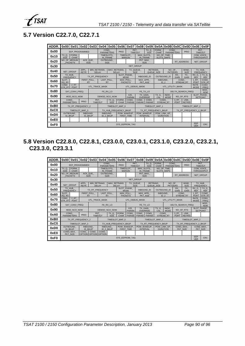
TSAT 2100 / 2150 - Telemetry and data transfer via SATellite
TSAT 2100 / 2150 Configuration Parameter Description, January 2013 Page 90 of 96
5.7 Version C22.7.0, C22.7.1
ADDR. 0x00 0x01 0x02 0x03 0x04 0x05 0x06 0x07 0x08 0x09 0x0A 0x0B 0x0C 0x0D 0x0E 0x0F0x00 EEP_PROGRAMMED
COM1_ PARAMETERS PRIO
PKT_ TIMEOUT
TX_Q_ SIZE
FORW_ CHAR
COM2_ PARAMETERS PRIO
PKT_ TIMEOUT
0x10 TX_Q_ SIZE
FORW_ CHAR
TIMESLOTS_ IN_FRAME
TIMESLOT_ MARGIN
MAX_SLOTS_ IN_FRAME
NO_OF_TIME SLOTS_MAPS COM_VOICE_
THROUGHPUT
0x20 NO_OF_MEDIUM_PACKETS
ACK_QUE_ SIZE
OUTBOUND_ SIZE
PKT_MAX_ SIZE RT_ADDRESS NET_GROUP
0x30 NET_GROUP
0x40 NET_GROUP APPL_ RETR.
MIN_RETRANS_ DELAY
MAX_RETRANS_DELAY
TX_QUEUE_ SIZE
RETRANS_ QUEUE_SIZE
NO_OF_ PKTIZERS
WIND_ SIZE
TX_HUB_ FREQUENCY
0x50 TX_HUB_ FREQUENCY TX_RT_FREQUENCY
SLOT_PHASE_ MODE INBOUND_ID OUTBOUND_ID
RX_ GAIN
TX_ GAIN
RX_G_ REF
TX_G_ REF
0x60 SLOT_ RQ_RV FIRST_POLL_
RT LAST_POLL_
RT MAX_POLL_
PACKETS MAX_APPL_
PKT_AGE INBOUND_
ID_2 COM1_
STREAM_RT 1_RT_ PORT
COM2_STR_RT
0x70 COM2_STR_RT
2_RT_ PORT UTL_TRACE_MASK UTL_DEBUG_MASK UTL_UTILITY_MASK
RATE_MODE
CONV_FREQ
0x80 SAT_CONV_FREQ FE_RX_LO FE_TX_LO DELTA_SEARCH_FREQ MOD_ NOM
0x90 MOD_NCO_NOM DEMOD_NCO_NOM X25_
PARAMTX_GAIN_ OVERRIDE
TX_G_ CAL
INDIC_ MODE NO_OF_RTS
SLOT_PHASE_ SETPOINT
0xA0 COM3_ PARAMETERS PRIO
PKT_ TIMEOUT
TX_Q_ SIZE
FORW_ CHAR
COM1_ PARAM
COM2_PARAM
COM3_PARAM
COM3_ STREAM_RT
3_RT_ PORT
LINK_ RETRIS
0xB0 TX_RT_FREQUENCY_2 TIMESLOT_MAP_0 TIMESLOT_MAP_1 TIMESLOT_MAP_2
0xC0 TIMESLOT_MAP_3 TX_HUB_FREQUENCY_BKUP TX_RT_FREQUENCY_BKUP TX_RT_FREQUENCY_2_BKUP
0xD0 OUTBOUND_ ID_BKUP
INBOUND_ ID_BKUP
INBOUND_ ID_2_BKUP
POW_WAKEUP_ FIRST_TIME
POW_WAKEUP_INTERVAL
POW_LINK_UP_ DURATION
0xE0
0xF0 SYS_EEPROM_TAG EEP VER
CRC
5.8 Version C22.8.0, C22.8.1, C23.0.0, C23.0.1, C23.1.0, C23.2.0, C23.2.1,
C23.3.0, C23.3.1
ADDR. 0x00 0x01 0x02 0x03 0x04 0x05 0x06 0x07 0x08 0x09 0x0A 0x0B 0x0C 0x0D 0x0E 0x0F0x00 EEP_PROGRAMMED
COM1_ PARAMETERS PRIO
PKT_ TIMEOUT
TX_Q_ SIZE
FORW_ CHAR
COM2_ PARAMETERS PRIO
PKT_ TIMEOUT
0x10 TX_Q_ SIZE
FORW_ CHAR
TIMESLOTS_ IN_FRAME
TIMESLOT_ MARGIN
MAX_SLOTS_ IN_FRAME
NO_OF_TIME SLOTS_MAPS COM_VOICE_
THROUGHPUT
0x20 NO_OF_MEDIUM_PACKETS
ACK_QUE_ SIZE
OUTBOUND_ SIZE
PKT_MAX_ SIZE RT_ADDRESS NET_GROUP
0x30 NET_GROUP
0x40 NET_GROUP APPL_ RETR.
MIN_RETRANS_ DELAY
MAX_RETRANS_DELAY
TX_QUEUE_ SIZE
RETRANS_ QUEUE_SIZE
NO_OF_ PKTIZERS
WIND_ SIZE
TX_HUB_ FREQUENCY
0x50 TX_HUB_ FREQUENCY TX_RT_FREQUENCY
SLOT_PHASE_ MODE INBOUND_ID OUTBOUND_ID
RX_ GAIN
TX_ GAIN
RX_G_ REF
TX_G_ REF
0x60 SLOT_ RQ_RV FIRST_POLL_
RT LAST_POLL_
RT MAX_POLL_
PACKETS MAX_APPL_
PKT_AGE INBOUND_
ID_2 COM1_
STREAM_RT 1_RT_ PORT
COM2_STR_RT
0x70 COM2_STR_RT
2_RT_ PORT UTL_TRACE_MASK UTL_DEBUG_MASK UTL_UTILITY_MASK
RATE_MODE
CONV_FREQ
0x80 SAT_CONV_FREQ FE_RX_LO FE_TX_LO DELTA_SEARCH_FREQ MOD_ NOM
0x90 MOD_NCO_NOM DEMOD_NCO_NOM X25_
PARAMTX_GAIN_ OVERRIDE
TX_G_ CAL
INDIC_ MODE NO_OF_RTS
SLOT_PHASE_ SETPOINT
0xA0 COM3_ PARAMETERS PRIO
PKT_ TIMEOUT
TX_Q_ SIZE
FORW_ CHAR
COM1_ PARAM
COM2_PARAM
COM3_PARAM
COM3_ STREAM_RT
3_RT_ PORT
LINK_ RETRIS
0xB0 TX_RT_FREQUENCY_2 TIMESLOT_MAP_0 TIMESLOT_MAP_1 TIMESLOT_MAP_2
0xC0 TIMESLOT_MAP_3 TX_HUB_FREQUENCY_BKUP TX_RT_FREQUENCY_BKUP TX_RT_FREQUENCY_2_BKUP
0xD0 OUTBOUND_ ID_BKUP
INBOUND_ ID_BKUP
INBOUND_ ID_2_BKUP
POW_WAKEUP_ FIRST_TIME
POW_WAKEUP_INTERVAL
POW_LINK_UP_ DURATION
COM1_MAX_ PKT_SIZE
COM2_MAX_ PKT_SIZE
0xE0 COM3_MAX_ PKT_SIZE
COM1_OPTION
COM2_OPTION
COM3_OPTION
0xF0 SYS_EEPROM_TAG EEP VER
CRC

TSAT 2100 / 2150 - Telemetry and data transfer via SATellite
TSAT 2100 / 2150 Configuration Parameter Description, January 2013 Page 91 of 96
5.9 Version C23.4.0, C23.5.0, C23.5.1
ADDR. 0x00 0x01 0x02 0x03 0x04 0x05 0x06 0x07 0x08 0x09 0x0A 0x0B 0x0C 0x0D 0x0E 0x0F0x00 EEP_PROGRAMMED
COM1_ PARAMETERS PRIO
PKT_ TIMEOUT
TX_Q_ SIZE
FORW_ CHAR
COM2_ PARAMETERS PRIO
PKT_ TIMEOUT
0x10 TX_Q_ SIZE
FORW_ CHAR
TIMESLOTS_ IN_FRAME
TIMESLOT_ MARGIN
MAX_SLOTS_ IN_FRAME
NO_OF_TIME SLOTS_MAPS COM_VOICE_
THROUGHPUT
0x20 NO_OF_MEDIUM_PACKETS
ACK_QUE_ SIZE
OUTBOUND_ SIZE
PKT_MAX_ SIZE RT_ADDRESS NET_GROUP
0x30 NET_GROUP
0x40 NET_GROUP APPL_ RETR.
MIN_RETRANS_ DELAY
MAX_RETRANS_DELAY
TX_QUEUE_ SIZE
RETRANS_ QUEUE_SIZE
NO_OF_ PKTIZERS
WIND_ SIZE
TX_HUB_ FREQUENCY
0x50 TX_HUB_ FREQUENCY TX_RT_FREQUENCY
SLOT_PHASE_ MODE INBOUND_ID OUTBOUND_ID
RX_ GAIN
TX_ GAIN
RX_G_ REF
TX_G_ REF
0x60 SLOT_ RQ_RV FIRST_POLL_
RT LAST_POLL_
RT MAX_POLL_
PACKETS MAX_APPL_
PKT_AGE INBOUND_
ID_2 COM1_
STREAM_RT 1_RT_ PORT
COM2_STR_RT
0x70 COM2_STR_RT
2_RT_ PORT UTL_TRACE_MASK UTL_DEBUG_MASK UTL_UTILITY_MASK
RATE_MODE
CONV_FREQ
0x80 SAT_CONV_FREQ FE_RX_LO FE_TX_LO DELTA_SEARCH_FREQ MOD_ NOM
0x90 MOD_NCO_NOM DEMOD_NCO_NOM X25_
PARAMTX_GAIN_ OVERRIDE
TX_G_ CAL
INDIC_ MODE NO_OF_RTS
SLOT_PHASE_ SETPOINT
0xA0 COM3_ PARAMETERS PRIO
PKT_ TIMEOUT
TX_Q_ SIZE
FORW_ CHAR
COM1_ PARAM
COM2_PARAM
COM3_PARAM
COM3_ STREAM_RT
3_RT_ PORT
LINK_ RETRIS
COM_MAX_NETW_PKT_AGE
0xB0 TX_RT_FREQUENCY_2 TIMESLOT_MAP_0 TIMESLOT_MAP_1 TIMESLOT_MAP_2
0xC0 TIMESLOT_MAP_3 TX_HUB_FREQUENCY_BKUP TX_RT_FREQUENCY_BKUP TX_RT_FREQUENCY_2_BKUP
0xD0 OUTBOUND_ ID_BKUP
INBOUND_ ID_BKUP
INBOUND_ ID_2_BKUP
POW_WAKEUP_ FIRST_TIME
POW_WAKEUP_INTERVAL
POW_LINK_UP_ DURATION
COM1_MAX_ PKT_SIZE
COM2_MAX_ PKT_SIZE
0xE0 COM3_MAX_ PKT_SIZE
COM1_OPTION
COM2_OPTION
COM3_OPTION
POW_HPA_ON
POW_HPA_OFF
POW_ POLL
0xF0 SYS_EEPROM_TAG EEP VER
CRC
5.10 Version C23.5.2, C24.0.0
ADDR. 0x00 0x01 0x02 0x03 0x04 0x05 0x06 0x07 0x08 0x09 0x0A 0x0B 0x0C 0x0D 0x0E 0x0F0x00 EEP_PROGRAMMED
COM1_ PARAMETERS PRIO
PKT_ TIMEOUT
TX_Q_ SIZE
FORW_ CHAR
COM2_ PARAMETERS PRIO
PKT_ TIMEOUT
0x10 TX_Q_ SIZE
FORW_ CHAR
TIMESLOTS_ IN_FRAME
TIMESLOT_ MARGIN
MAX_SLOTS_ IN_FRAME
NO_OF_TIME SLOTS_MAPS COM_VOICE_
THROUGHPUT
0x20 NO_OF_MEDIUM_PACKETS
ACK_QUE_ SIZE
OUTBOUND_ SIZE
MIN_RR _DELAY
MAX_RR _DELAY
PKT_MAX_ SIZE RT_ADDRESS NET_GROUP
0x30 NET_GROUP
0x40 NET_GROUP APPL_ RETR.
MIN_RETRANS_ DELAY
MAX_RETRANS_DELAY
TX_QUEUE_ SIZE
RETRANS_ QUEUE_SIZE
NO_OF_ PKTIZERS
WIND_ SIZE
TX_HUB_ FREQUENCY
0x50 TX_HUB_ FREQUENCY TX_RT_FREQUENCY
SLOT_PHASE_ MODE INBOUND_ID OUTBOUND_ID
RX_ GAIN
TX_ GAIN
RX_G_ REF
TX_G_ REF
0x60 SLOT_ RQ_RV FIRST_POLL_
RT LAST_POLL_
RT MAX_POLL_
PACKETS MAX_APPL_
PKT_AGE INBOUND_
ID_2 COM1_
STREAM_RT 1_RT_ PORT
COM2_STR_RT
0x70 COM2_STR_RT
2_RT_ PORT UTL_TRACE_MASK UTL_DEBUG_MASK UTL_UTILITY_MASK
RATE_MODE
CONV_FREQ
0x80 SAT_CONV_FREQ FE_RX_LO FE_TX_LO DELTA_SEARCH_FREQ MOD_ NOM
0x90 MOD_NCO_NOM DEMOD_NCO_NOM X25_
PARAMTX_GAIN_ OVERRIDE
TX_G_ CAL
INDIC_ MODE NO_OF_RTS
SLOT_PHASE_ SETPOINT
0xA0 COM3_ PARAMETERS PRIO
PKT_ TIMEOUT
TX_Q_ SIZE
FORW_ CHAR
COM1_ PARAM
COM2_PARAM
COM3_PARAM
COM3_ STREAM_RT
3_RT_ PORT
LINK_ RETRIS
COM_MAX_NETW_PKT_AGE
0xB0 TX_RT_FREQUENCY_2 TIMESLOT_MAP_0 TIMESLOT_MAP_1 TIMESLOT_MAP_2
0xC0 TIMESLOT_MAP_3 TX_HUB_FREQUENCY_BKUP TX_RT_FREQUENCY_BKUP TX_RT_FREQUENCY_2_BKUP
0xD0 OUTBOUND_ ID_BKUP
INBOUND_ ID_BKUP
INBOUND_ ID_2_BKUP
POW_WAKEUP_ FIRST_TIME
POW_WAKEUP_INTERVAL
POW_LINK_UP_ DURATION
COM1_MAX_ PKT_SIZE
COM2_MAX_ PKT_SIZE
0xE0 COM3_MAX_ PKT_SIZE
COM1_OPTION
COM2_OPTION
COM3_OPTION
POW_ HPA_ON
POW_HPA_OFF
POW_ POLL
0xF0 SYS_EEPROM_TAG EEP VER CRC

TSAT 2100 / 2150 - Telemetry and data transfer via SATellite
TSAT 2100 / 2150 Configuration Parameter Description, January 2013 Page 92 of 96
5.11 Version C24.1.0
ADDR. 0x00 0x01 0x02 0x03 0x04 0x05 0x06 0x07 0x08 0x09 0x0A 0x0B 0x0C 0x0D 0x0E 0x0F0x00 EEP_PROGRAMMED
COM1_ PARAMETERS PRIO
PKT_ TIMEOUT
TX_Q_ SIZE
FORW_ CHAR
COM2_ PARAMETERS PRIO
PKT_ TIMEOUT
0x10 TX_Q_ SIZE
FORW_ CHAR
TIMESLOTS_ IN_FRAME
TIMESLOT_ MARGIN
MAX_SLOTS_ IN_FRAME
NO_OF_TIME SLOTS_MAPS
TX_FREQUENCY_ADJUST
COM_VOICE_ THROUGHPUT
0x20 NO_OF_MEDIUM_PACKETS
ACK_QUE_ SIZE
OUTBOUND_ SIZE
MIN_RR _DELAY
MAX_RR _DELAY
PKT_MAX_ SIZE RT_ADDRESS NET_GROUP
0x30 NET_GROUP
0x40 NET_GROUP APPL_ RETR.
MIN_RETRANS_ DELAY
MAX_RETRANS_DELAY
TX_QUEUE_ SIZE
RETRANS_ QUEUE_SIZE
NO_OF_ PKTIZERS
WIND_ SIZE
TX_HUB_ FREQUENCY
0x50 TX_HUB_ FREQUENCY TX_RT_FREQUENCY
SLOT_PHASE_ MODE INBOUND_ID OUTBOUND_ID
RX_ GAIN
TX_ GAIN
RX_G_ REF
TX_G_ REF
0x60 SLOT_ RQ_RV FIRST_POLL_
RT LAST_POLL_
RT MAX_POLL_
PACKETS MAX_APPL_
PKT_AGE INBOUND_
ID_2 COM1_
STREAM_RT 1_RT_ PORT
COM2_STR_RT
0x70 COM2_STR_RT
2_RT_ PORT UTL_TRACE_MASK UTL_DEBUG_MASK UTL_UTILITY_MASK
RATE_MODE
CONV_FREQ
0x80 SAT_CONV_FREQ FE_RX_LO FE_TX_LO DELTA_SEARCH_FREQ MOD_ NOM
0x90 MOD_NCO_NOM DEMOD_NCO_NOM X25_
PARAMTX_GAIN_ OVERRIDE
TX_G_ CAL
INDIC_ MODE NO_OF_RTS
SLOT_PHASE_ SETPOINT
0xA0 COM3_ PARAMETERS PRIO
PKT_ TIMEOUT
TX_Q_ SIZE
FORW_ CHAR
COM1_ PARAM
COM2_PARAM
COM3_PARAM
COM3_ STREAM_RT
3_RT_ PORT
LINK_ RETRIS
COM_MAX_NETW_PKT_AGE
0xB0 TX_RT_FREQUENCY_2 TIMESLOT_MAP_0 TIMESLOT_MAP_1 TIMESLOT_MAP_2
0xC0 TIMESLOT_MAP_3 TX_HUB_FREQUENCY_BKUP TX_RT_FREQUENCY_BKUP TX_RT_FREQUENCY_2_BKUP
0xD0 OUTBOUND_ ID_BKUP
INBOUND_ ID_BKUP
INBOUND_ ID_2_BKUP
POW_WAKEUP_ FIRST_TIME
POW_WAKEUP_INTERVAL
POW_LINK_UP_ DURATION
COM1_MAX_ PKT_SIZE
COM2_MAX_ PKT_SIZE
0xE0 COM3_MAX_ PKT_SIZE
COM1_OPTION
COM2_OPTION
COM3_OPTION
POW_ HPA_ON
POW_HPA_OFF
POW_ POLL
0xF0 SYS_EEPROM_TAG EEP VER CRC
5.12 Version C24.2.0, C24.2.1, C24.2.2, C24.2.3, C24.2.4
ADDR. 0x00 0x01 0x02 0x03 0x04 0x05 0x06 0x07 0x08 0x09 0x0A 0x0B 0x0C 0x0D 0x0E 0x0F0x00 EEP_PROGRAMMED
COM1_ PARAMETERS PRIO
PKT_ TIMEOUT
TX_Q_ SIZE
FORW_ CHAR
COM2_ PARAMETERS PRIO
PKT_ TIMEOUT
0x10 TX_Q_ SIZE
FORW_ CHAR
TIMESLOTS_ IN_FRAME
TIMESLOT_ MARGIN
MAX_SLOTS_ IN_FRAME
NO_OF_TIME SLOTS_MAPS
TX_FREQUENCY_ADJUST
COM_VOICE_ THROUGHPUT
0x20 NO_OF_MEDIUM_PACKETS
ACK_QUE_ SIZE
OUTBOUND_ SIZE
MIN_RR _DELAY
MAX_RR _DELAY
PKT_MAX_ SIZE
MANAG_ PRIO RT_ADDRESS NET_GROUP
0x30 NET_GROUP
0x40 NET_GROUP APPL_ RETR.
MIN_RETRANS_ DELAY
MAX_RETRANS_DELAY
TX_QUEUE_ SIZE
RETRANS_ QUEUE_SIZE
NO_OF_ PKTIZERS
WIND_ SIZE
TX_HUB_ FREQUENCY
0x50 TX_HUB_ FREQUENCY TX_RT_FREQUENCY
SLOT_PHASE_ MODE INBOUND_ID OUTBOUND_ID
RX_ GAIN
TX_ GAIN
RX_G_ REF
TX_G_ REF
0x60 SLOT_ RQ_RV
TIMSLOT_COM
FIRST_POLL_ RT
LAST_POLL_ RT
MAX_POLL_ PACKETS
MAX_APPL_ PKT_AGE
INBOUND_ ID_2
COM1_ STREAM_RT
1_RT_ PORT
COM2_STR_RT
0x70 COM2_STR_RT
2_RT_ PORT UTL_TRACE_MASK UTL_DEBUG_MASK UTL_UTILITY_MASK
RATE_MODE
CONV_FREQ
0x80 SAT_CONV_FREQ FE_RX_LO FE_TX_LO DELTA_SEARCH_FREQ MOD_ NOM
0x90 MOD_NCO_NOM DEMOD_NCO_NOM X25_
PARAMTX_GAIN_ OVERRIDE
TX_G_ CAL
INDIC_ MODE NO_OF_RTS
SLOT_PHASE_ SETPOINT
0xA0 COM3_ PARAMETERS PRIO
PKT_ TIMEOUT
TX_Q_ SIZE
FORW_ CHAR
COM1_ PARAM
COM2_PARAM
COM3_PARAM
COM3_ STREAM_RT
3_RT_ PORT
LINK_ RETRIS
COM_MAX_NETW_PKT_AGE
0xB0 TX_RT_FREQUENCY_2 TIMESLOT_MAP_0 TIMESLOT_MAP_1 TIMESLOT_MAP_2
0xC0 TIMESLOT_MAP_3 TX_HUB_FREQUENCY_BKUP TX_RT_FREQUENCY_BKUP TX_RT_FREQUENCY_2_BKUP
0xD0 OUTBOUND_ ID_BKUP
INBOUND_ ID_BKUP
INBOUND_ ID_2_BKUP
POW_WAKEUP_ FIRST_TIME
POW_WAKEUP_INTERVAL
POW_LINK_UP_ DURATION
COM1_MAX_ PKT_SIZE
COM2_MAX_ PKT_SIZE
0xE0 COM3_MAX_ PKT_SIZE
COM1_OPTION
COM2_OPTION
COM3_OPTION
POW_ HPA_ON
POW_HPA_OFF
POW_ POLL
0xF0 SYS_EEPROM_TAG EEP VER CRC

TSAT 2100 / 2150 - Telemetry and data transfer via SATellite
TSAT 2100 / 2150 Configuration Parameter Description, January 2013 Page 93 of 96
5.13 Version C24.3.0, C24.3.1, C24.4.0, C24.4.1
ADDR. 0x00 0x01 0x02 0x03 0x04 0x05 0x06 0x07 0x08 0x09 0x0A 0x0B 0x0C 0x0D 0x0E 0x0F0x00 EEP_PROGRAMMED
COM1_ PARAMETERS PRIO
PKT_ TIMEOUT
TX_Q_ SIZE
FORW_ CHAR
COM2_ PARAMETERS PRIO
PKT_ TIMEOUT
0x10 TX_Q_ SIZE
FORW_ CHAR
START_POLL_ RT
TIMESLOTS_ IN_FRAME
TIMESLOT_ MARGIN
MAX_SLOTS_ IN_FRAME
NO_OF_TIME SLOTS_MAPS
TX_FREQUENCY_ADJUST
COM_VOICE_ THROUGHPUT
0x20 NO_OF_MEDIUM_PACKETS
ACK_QUE_ SIZE
OUTBOUND_ SIZE
MIN_RR _DELAY
MAX_RR _DELAY
PKT_MAX_ SIZE
MANAG_ PRIO RT_ADDRESS NET_GROUP
0x30 NET_GROUP
0x40 NET_GROUP APPL_ RETR.
MIN_RETRANS_ DELAY
MAX_RETRANS_DELAY
TX_QUEUE_ SIZE
RETRANS_ QUEUE_SIZE
NO_OF_ PKTIZERS
WIND_ SIZE
TX_HUB_ FREQUENCY
0x50 TX_HUB_ FREQUENCY TX_RT_FREQUENCY
SLOT_PHASE_ MODE INBOUND_ID OUTBOUND_ID
RX_ GAIN
TX_ GAIN
RX_G_ REF
TX_G_ REF
0x60 SLOT_ RQ_RV
TIMSLOT_COM
FIRST_POLL_ RT
LAST_POLL_ RT
MAX_POLL_ PACKETS
MAX_APPL_ PKT_AGE
INBOUND_ ID_2
COM1_ STREAM_RT
1_RT_ PORT
COM2_STR_RT
0x70 COM2_STR_RT
2_RT_ PORT UTL_TRACE_MASK UTL_DEBUG_MASK UTL_UTILITY_MASK
RATE_MODE
CONV_FREQ
0x80 SAT_CONV_FREQ FE_RX_LO FE_TX_LO DELTA_SEARCH_FREQ MOD_ NOM
0x90 MOD_NCO_NOM DEMOD_NCO_NOM X25_
PARAMTX_GAIN_ OVERRIDE
TX_G_ CAL
INDIC_ MODE NO_OF_RTS
SLOT_PHASE_ SETPOINT
0xA0 COM3_ PARAMETERS PRIO
PKT_ TIMEOUT
TX_Q_ SIZE
FORW_ CHAR
COM1_ PARAM
COM2_PARAM
COM3_PARAM
COM3_ STREAM_RT
3_RT_ PORT
LINK_ RETRIS
COM_MAX_NETW_PKT_AGE
0xB0 TX_RT_FREQUENCY_2 TIMESLOT_MAP_0 TIMESLOT_MAP_1 TIMESLOT_MAP_2
0xC0 TIMESLOT_MAP_3 TX_HUB_FREQUENCY_BKUP TX_RT_FREQUENCY_BKUP TX_RT_FREQUENCY_2_BKUP
0xD0 OUTBOUND_ ID_BKUP
INBOUND_ ID_BKUP
INBOUND_ ID_2_BKUP
POW_WAKEUP_ FIRST_TIME
POW_WAKEUP_INTERVAL
POW_LINK_UP_ DURATION
COM1_MAX_ PKT_SIZE
COM2_MAX_ PKT_SIZE
0xE0 COM3_MAX_ PKT_SIZE
COM1_OPTION
COM2_OPTION
COM3_OPTION
POW_ HPA_ON
POW_HPA_OFF
POW_ POLL
0xF0 SYS_EEPROM_TAG EEP VER CRC
5.14 Version C24.4.2, C24.4.3, C24.4.4, C24.4.5, C24.4.6
ADDR. 0x00 0x01 0x02 0x03 0x04 0x05 0x06 0x07 0x08 0x09 0x0A 0x0B 0x0C 0x0D 0x0E 0x0F0x00 EEP_PROGRAMMED
COM1_ PARAMETERS PRIO
PKT_ TIMEOUT
TX_Q_ SIZE
FORW_ CHAR
COM2_ PARAMETERS PRIO
PKT_ TIMEOUT
0x10 TX_Q_ SIZE
FORW_ CHAR
START_POLL_ RT
TIMESLOTS_ IN_FRAME
TIMESLOT_ MARGIN
MAX_SLOTS_ IN_FRAME
NO_OF_TIME SLOTS_MAPS
TX_FREQUENCY_ADJUST
COM_VOICE_ THROUGHPUT
0x20 NO_OF_MEDIUM_PACKETS
ACK_QUE_ SIZE
OUTBOUND_ SIZE
MIN_RR _DELAY
MAX_RR _DELAY
PKT_MAX_ SIZE
MANAG_ PRIO RT_ADDRESS NET_GROUP
0x30 NET_GROUP
0x40 NET_GROUP APPL_ RETR.
MIN_RETRANS_ DELAY
MAX_RETRANS_DELAY
TX_QUEUE_ SIZE
RETRANS_ QUEUE_SIZE
NO_OF_ PKTIZERS
WIND_ SIZE
TX_HUB_ FREQUENCY
0x50 TX_HUB_ FREQUENCY TX_RT_FREQUENCY
SLOT_PHASE_ MODE INBOUND_ID OUTBOUND_ID
RX_ GAIN
TX_ GAIN
RX_G_ REF
TX_G_ REF
0x60 SLOT_ RQ_RV
TIMSLOT_COM
FIRST_POLL_ RT
LAST_POLL_ RT
MAX_POLL_ PACKETS
MAX_APPL_ PKT_AGE
INBOUND_ ID_2
COM1_ STREAM_RT
1_RT_ PORT
COM2_STR_RT
0x70 COM2_STR_RT
2_RT_ PORT UTL_TRACE_MASK UTL_DEBUG_MASK UTL_UTILITY_MASK
RATE_MODE
CONV_FREQ
0x80 SAT_CONV_FREQ FE_RX_LO FE_TX_LO DELTA_SEARCH_FREQ MOD_ NOM
0x90 MOD_NCO_NOM DEMOD_NCO_NOM X25_
PARAMTX_GAIN_ OVERRIDE
TX_G_ CAL
INDIC_ MODE NO_OF_RTS
SLOT_PHASE_ SETPOINT
0xA0 COM3_ PARAMETERS PRIO
PKT_ TIMEOUT
TX_Q_ SIZE
FORW_ CHAR
COM1_ PARAM
COM2_PARAM
COM3_PARAM
COM3_ STREAM_RT
3_RT_ PORT
LINK_ RETRIS
COM_MAX_NETW_PKT_AGE
0xB0 TX_RT_FREQUENCY_2 TIMESLOT_MAP_0 TIMESLOT_MAP_1 TIMESLOT_MAP_2
0xC0 TIMESLOT_MAP_3 TX_HUB_FREQUENCY_BKUP TX_RT_FREQUENCY_BKUP TX_RT_FREQUENCY_2_BKUP
0xD0 OUTBOUND_ ID_BKUP
INBOUND_ ID_BKUP
INBOUND_ ID_2_BKUP
POW_WAKEUP_ FIRST_TIME
POW_WAKEUP_INTERVAL
POW_LINK_UP_ DURATION
COM1_MAX_ PKT_SIZE
COM2_MAX_ PKT_SIZE
0xE0 COM3_MAX_ PKT_SIZE
COM1_OPTION
COM2_OPTION
COM3_OPTION
POW_ HPA_ON
POW_HPA_OFF
POW_ POLL
TX_FREQUENCY_ADJUST_BKUP
0xF0 SYS_EEPROM_TAG EEP VER CRC

TSAT 2100 / 2150 - Telemetry and data transfer via SATellite
TSAT 2100 / 2150 Configuration Parameter Description, January 2013 Page 94 of 96
5.15 Version C24.4.7
ADDR. 0x00 0x01 0x02 0x03 0x04 0x05 0x06 0x07 0x08 0x09 0x0A 0x0B 0x0C 0x0D 0x0E 0x0F0x00 EEP_PROGRAMMED
COM1_ PARAMETERS PRIO
PKT_ TIMEOUT
TX_Q_ SIZE
FORW_ CHAR
COM2_ PARAMETERS PRIO
PKT_ TIMEOUT
0x10 TX_Q_ SIZE
FORW_ CHAR
START_POLL_ RT
TIMESLOTS_ IN_FRAME
TIMESLOT_ MARGIN
MAX_SLOTS_ IN_FRAME
NO_OF_TIME SLOTS_MAPS
TX_FREQUENCY_ADJUST
COM_VOICE_ THROUGHPUT
0x20 NO_OF_MEDIUM_PACKETS
ACK_QUE_ SIZE
OUTBOUND_ SIZE
MIN_RR _DELAY
MAX_RR _DELAY
PKT_MAX_ SIZE
MANAG_ PRIO RT_ADDRESS NET_GROUP
0x30 NET_GROUP
0x40 NET_GROUP APPL_ RETR.
MIN_RETRANS_ DELAY
MAX_RETRANS_DELAY
TX_QUEUE_ SIZE
RETRANS_ QUEUE_SIZE
NO_OF_ PKTIZERS
WIND_ SIZE
TX_HUB_ FREQUENCY
0x50 TX_HUB_ FREQUENCY TX_RT_FREQUENCY
SLOT_PHASE_ MODE INBOUND_ID OUTBOUND_ID
RX_ GAIN
TX_ GAIN
RX_G_ REF
TX_G_ REF
0x60 SLOT_ RQ_RV
TIMSLOT_COM
FIRST_POLL_ RT
LAST_POLL_ RT
MAX_POLL_ PACKETS
MAX_APPL_ PKT_AGE
INBOUND_ ID_2
COM1_ STREAM_RT
1_RT_ PORT
COM2_STR_RT
0x70 COM2_STR_RT
2_RT_ PORT UTL_TRACE_MASK UTL_DEBUG_MASK UTL_UTILITY_MASK
RATE_MODE
CONV_FREQ
0x80 SAT_CONV_FREQ FE_RX_LO FE_TX_LO DELTA_SEARCH_FREQ MOD_ NOM
0x90 MOD_NCO_NOM DEMOD_NCO_NOM X25_
PARAMTX_GAIN_ OVERRIDE
TX_G_ CAL
INDIC_ MODE NO_OF_RTS
SLOT_PHASE_ SETPOINT
0xA0 COM3_ PARAMETERS PRIO
PKT_ TIMEOUT
TX_Q_ SIZE
FORW_ CHAR
COM1_ PARAM
COM2_PARAM
COM3_PARAM
COM3_ STREAM_RT
3_RT_ PORT
LINK_ RETRIS
COM_MAX_NETW_PKT_AGE
0xB0 TX_RT_FREQUENCY_2 TIMESLOT_MAP_0 TIMESLOT_MAP_1 TIMESLOT_MAP_2
0xC0 TIMESLOT_MAP_3 TX_HUB_FREQUENCY_BKUP TX_RT_FREQUENCY_BKUP TX_RT_FREQUENCY_2_BKUP
0xD0 OUTBOUND_ ID_BKUP
INBOUND_ ID_BKUP
INBOUND_ ID_2_BKUP
POW_WAKEUP_ FIRST_TIME
POW_WAKEUP_INTERVAL
POW_LINK_UP_ DURATION
COM1_MAX_ PKT_SIZE
COM2_MAX_ PKT_SIZE
0xE0 COM3_MAX_ PKT_SIZE
COM1_OPTION
COM2_OPTION
COM3_OPTION
POW_ HPA_ON
POW_HPA_OFF
POW_ POLL
TX_FREQUENCY_ADJUST_BKUP
TX_FREQUENCY_ADJUST_2
TX_FREQUENCY_ADJUST_2_BKUP
0xF0 SYS_EEPROM_TAG EEP VER CRC
5.16 Version C25.0.0, C25.0.1, C25.0.2, C25.0.3, C25.0.4, C25.0.5
ADDR. 0x00 0x01 0x02 0x03 0x04 0x05 0x06 0x07 0x08 0x09 0x0A 0x0B 0x0C 0x0D 0x0E 0x0F0x00 EEP_PROGRAMMED
COM1_ PARAMETERS PRIO
COM1_PKT_ TIMEOUT
TX_Q_ SIZE 1
FORW_ CHAR
COM2_ PARAMETERS PRIO
COM2_PKT_ TIMEOUT
0x10 TX_Q_ SIZE 2
FORW_ CHAR
START_ POLL_RT
TIMESLOTS_ IN_FRAME
TIMESLOT_ MARGIN TX_FREQUENCY_
ADJUST LCC_VOICE_
THROUGHPUT
0x20 PKT_POOL_ SIZE OUTBOUND_
SIZE MIN_RR _DELAY
MAX_RR _DELAY
PKT_ MAX_SIZE
MANAG_PRIO IS_HUB RT_ADDRESS NET_GROUP [1]
0x30 NET_GROUP [2] NET_GROUP [3] NET_GROUP [4] NET_GROUP [5]
0x40 APPL_ RETR.
MIN_RETRANS_ DELAY
MAX_RETRANS_DELAY
LCC_TX_ QUEUE_SIZE
LCC_RETRANS_ QUEUE_SIZE
LCC_NO_OF_ PKTIZERS
WIND_ SIZE
TX_HUB_ FREQUENCY
0x50 TX_HUB_ FREQUENCY PHL_TX_RT_FREQUENCY
SLOT_PHASE_ MODE INBOUND_ID OUTBOUND_ID GAIN_
TX_ E2E GAIN_ TX_REF
0x60 SLOT_ RQ_RV
TIMSLOT_COM
FIRST_ POLL_RT
LAST_ POLL_RT
MAX_POLL_ PACKETS
MAX_APPL_ PKT_AGE
INBOUND_ ID_2
COM1_ STREAM_RT
1_RT_ PORT
COM2_STR_RT
0x70 COM2_ STR_RT
2_RT_ PORT UTL_TRACE_MASK UTL_DEBUG_MASK UTL_UTILITY_MASK
RATE_ MODE
CONV_FREQ
0x80 PHL_SAT_CONV_FREQ PHL_FE_RX_LO PHL_FE_TX_LO PHL_DELTA_SEARCH_FREQ
0x90 X25_
PARAMGAIN_TX
OVERRIDE GAIN_
TX_CALINDIC_ MODE NO_OF_RTS
SLOT_PHASE_ SETPOINT
0xA0 COM3_ PARAMETERS PRIO
COM3_PKT_ TIMEOUT
TX_Q_ SIZE 3
FORW_ CHAR
COM1_ PARAM
COM2_PARAM
COM3_PARAM
COM3_ STREAM_RT
3_RT_ PORT
LINK_ RETRIS
LCC_MAX_MNGT_PKT_AGE
0xB0 TX_RT_FREQUENCY_2 TIMESLOT_MAP_0 TIMESLOT_MAP_1 TIMESLOT_MAP_2
0xC0 TIMESLOT_MAP_3 TX_HUB_FREQUENCY_BKUP TX_RT_FREQUENCY_BKUP TX_RT_FREQUENCY_2_BKUP
0xD0 OUTBOUND_ ID_BKUP
INBOUND_ ID_BKUP
INBOUND_ ID_2_BKUP
POW_WAKEUP_ FIRST_TIME
POW_WAKEUP_INTERVAL
POW_LINK_UP_ DURATION
COM1_MAX_ PKT_SIZE
COM2_MAX_ PKT_SIZE
0xE0 COM3_MAX_ PKT_SIZE
COM1_OPTION
COM2_OPTION
COM3_OPTION
POW_ HPA_ON
POW_HPA_OFF
POW_ POLL
TX_FREQUENCY_ADJUST_BKUP
TX_FREQUENCY_ADJUST_2
TX_FREQUENCY_ADJUST_2_BKUP
0xF0 SYS_EEPROM_TAG EEP VER CRC

TSAT 2100 / 2150 - Telemetry and data transfer via SATellite
TSAT 2100 / 2150 Configuration Parameter Description, January 2013 Page 95 of 96
5.17 Version C25.1.0, C25.1.1, C25.1.2, C25.1.3, C25.1.4, C25.1.5, C25.1.6,
C25.1.7, C25.1.8
ADDR. 0x00 0x01 0x02 0x03 0x04 0x05 0x06 0x07 0x08 0x09 0x0A 0x0B 0x0C 0x0D 0x0E 0x0F0x00 EEP_PROGRAMMED
COM1_ PARAMETERS PRIO
COM1_PKT_ TIMEOUT
TX_Q_ SIZE 1
FORW_ CHAR
COM2_ PARAMETERS PRIO
COM2_PKT_ TIMEOUT
0x10 TX_Q_ SIZE 2
FORW_ CHAR
START_ POLL_RT
TIMESLOTS_ IN_FRAME
TIMESLOT_ MARGIN TX_FREQUENCY_
ADJUST LCC_VOICE_
THROUGHPUT
0x20 PKT_POOL_ SIZE OUTBOUND_
SIZE MIN_RR _DELAY
MAX_RR _DELAY
PKT_ MAX_SIZE
MANAG_ PRIO IS_HUB RT_ADDRESS NET_GROUP [1]
0x30 NET_GROUP [2] NET_GROUP [3] NET_GROUP [4] COM_SIGNAL_ DATA_DELAY
NET_GROUP [5]
0x40 COM_SIGNAL_ HOLD
APPL_ RETR.
MIN_RETRANS_ DELAY
MAX_RETRANS_DELAY
LCC_TX_ QUEUE_SIZE
LCC_RETRANS_ QUEUE_SIZE
LCC_NO_OF_ PKTIZERS
WIND_ SIZE
TX_HUB_ FREQUENCY
0x50 TX_HUB_ FREQUENCY PHL_TX_RT_FREQUENCY
SLOT_PHASE_ MODE INBOUND_ID OUTBOUND_ID GAIN_
TX_ E2E GAIN_ TX_REF
0x60 SLOT_ RQ_RV
TIMSLOT_COM
FIRST_ POLL_RT
LAST_ POLL_RT
MAX_POLL_ PACKETS
MAX_APPL_ PKT_AGE
INBOUND_ ID_2
COM1_ STREAM_RT
1_RT_ PORT
COM2_STR_RT
0x70 COM2_ STR_RT
2_RT_ PORT UTL_TRACE_MASK UTL_DEBUG_MASK UTL_UTILITY_MASK
RATE_ MODE
CONV_FREQ
0x80 PHL_SAT_CONV_FREQ PHL_FE_RX_LO PHL_FE_TX_LO PHL_DELTA_SEARCH_FREQ
0x90 X25_
PARAMGAIN_TX
OVERRIDE GAIN_
TX_CALINDIC_ MODE NO_OF_RTS
SLOT_PHASE_ SETPOINT
0xA0 COM3_ PARAMETERS PRIO
COM3_PKT_ TIMEOUT
TX_Q_ SIZE 3
FORW_ CHAR
COM1_ PARAM
COM2_PARAM
COM3_PARAM
COM3_ STREAM_RT
3_RT_ PORT
LINK_ RETRIS
LCC_MAX_MNGT_PKT_AGE
0xB0 TX_RT_FREQUENCY_2 TIMESLOT_MAP_0 TIMESLOT_MAP_1 TIMESLOT_MAP_2
0xC0 TIMESLOT_MAP_3 TX_HUB_FREQUENCY_BKUP TX_RT_FREQUENCY_BKUP TX_RT_FREQUENCY_2_BKUP
0xD0 OUTBOUND_ ID_BKUP
INBOUND_ ID_BKUP
INBOUND_ ID_2_BKUP
POW_WAKEUP_ FIRST_TIME
POW_WAKEUP_INTERVAL
POW_LINK_UP_ DURATION
COM1_MAX_ PKT_SIZE
COM2_MAX_ PKT_SIZE
0xE0 COM3_MAX_ PKT_SIZE
COM1_OPTION
COM2_OPTION
COM3_OPTION
POW_ HPA_ON
POW_HPA_OFF
POW_ POLL
TX_FREQUENCY_ADJUST_BKUP
TX_FREQUENCY_ADJUST_2
TX_FREQUENCY_ADJUST_2_BKUP
0xF0 SYS_EEPROM_TAG EEP VER CRC
5.18 Version C25.2.0, C25.2.1, C25.2.2, C25.2.3, C25.2.4, C25.2.5, C25.2.6,
C25.2.7, C25.2.8, C25.2.9
ADDR. 0x00 0x01 0x02 0x03 0x04 0x05 0x06 0x07 0x08 0x09 0x0A 0x0B 0x0C 0x0D 0x0E 0x0F0x00 EEP_PROGRAMMED
COM1_ PARAMETERS PRIO
COM1_PKT_ TIMEOUT
TX_Q_ SIZE 1
FORW_ CHAR
COM2_ PARAMETERS PRIO
COM2_PKT_ TIMEOUT
0x10 TX_Q_ SIZE 2
FORW_ CHAR
START_ POLL_RT
TIMESLOTS_ IN_FRAME
TIMESLOT_ MARGIN TX_FREQUENCY_
ADJUST LCC_VOICE_
THROUGHPUT
0x20 PKT_POOL_ SIZE OUTBOUND_
SIZE MIN_RR _DELAY
MAX_RR _DELAY
PKT_ MAX_SIZE
MANAG_ PRIO IS_HUB RT_ADDRESS NET_GROUP [1]
0x30 NET_GROUP [2] NET_GROUP [3] NET_GROUP [4] COM_SIGNAL_ DATA_DELAY
NET_GROUP [5]
0x40 COM_SIGNAL_ HOLD
APPL_ RETR.
MIN_RETRANS_ DELAY
MAX_RETRANS_DELAY
LCC_TX_ QUEUE_SIZE
LCC_RETRANS_ QUEUE_SIZE
LCC_NO_OF_ PKTIZERS
WIND_ SIZE
TX_HUB_ FREQUENCY
0x50 TX_HUB_ FREQUENCY PHL_TX_RT_FREQUENCY
SLOT_PHASE_ MODE INBOUND_ID OUTBOUND_ID GAIN_
TX_ E2E GAIN_ TX_REF
0x60 SLOT_ RQ_RV
TIMSLOT_COM
FIRST_ POLL_RT
LAST_ POLL_RT
MAX_POLL_ PACKETS
MAX_APPL_ PKT_AGE
INBOUND_ ID_2
COM1_ STREAM_RT
1_RT_ PORT
COM2_STR_RT
0x70 COM2_ STR_RT
2_RT_ PORT UTL_TRACE_MASK UTL_DEBUG_MASK UTL_UTILITY_MASK
RATE_ MODE
CONV_FREQ
0x80 PHL_SAT_CONV_FREQ PHL_FE_RX_LO PHL_FE_TX_LO PHL_DELTA_SEARCH_FREQ
0x90 X25_
PARAMGAIN_TX
OVERRIDE GAIN_
TX_CALINDIC_ MODE NO_OF_RTS
SLOT_PHASE_ SETPOINT
0xA0 COM3_ PARAMETERS PRIO
COM3_PKT_ TIMEOUT
TX_Q_ SIZE 3
FORW_ CHAR
COM1_ PARAM
COM2_PARAM
COM3_PARAM
COM3_ STREAM_RT
3_RT_ PORT
LINK_ RETRIS
LCC_MAX_MNGT_PKT_AGE
0xB0 TX_RT_FREQUENCY_2 TIMESLOT_MAP_0 TIMESLOT_MAP_1 TIMESLOT_MAP_2
0xC0 TIMESLOT_MAP_3 TX_HUB_FREQUENCY_BKUP TX_RT_FREQUENCY_BKUP TX_RT_FREQUENCY_2_BKUP
0xD0 OUTBOUND_ ID_BKUP
INBOUND_ ID_BKUP
INBOUND_ ID_2_BKUP
POW_WAKEUP_ FIRST_TIME
POW_WAKEUP_INTERVAL
POW_LINK_UP_ DURATION
COM1_MAX_ PKT_SIZE
COM2_MAX_ PKT_SIZE
0xE0 COM3_MAX_ PKT_SIZE
COM1_OPTION
COM2_OPTION
COM3_OPTION
POW_ HPA_ON
POW_HPA_OFF
POW_ POLL
TX_FREQUENCY_ADJUST_BKUP
TX_FREQUENCY_ADJUST_2
TX_FREQUENCY_ADJUST_2_BKUP
SWITCH_BACK_ TO_MAIN_HUB
0xF0 SYS_EEPROM_TAG EEP VER CRC

TSAT 2100 / 2150 - Telemetry and data transfer via SATellite
TSAT 2100 / 2150 Configuration Parameter Description, January 2013 Page 96 of 96
5.19 Version C25.3.0, C25.3.1, C25.3.2
ADDR. 0x00 0x01 0x02 0x03 0x04 0x05 0x06 0x07 0x08 0x09 0x0A 0x0B 0x0C 0x0D 0x0E 0x0F0x00 EEP_PROGRAMMED
COM1_ PARAMETERS PRIO
COM1_PKT_ TIMEOUT
TX_Q_ SIZE 1
FORW_ CHAR
COM2_ PARAMETERS PRIO
COM2_PKT_ TIMEOUT
0x10 TX_Q_ SIZE 2
FORW_ CHAR
START_ POLL_RT
TIMESLOTS_ IN_FRAME
TIMESLOT_ MARGIN TX_FREQUENCY_
ADJUST LCC_VOICE_
THROUGHPUT
0x20 PKT_POOL_ SIZE OUTBOUND_
SIZE MIN_RR _DELAY
MAX_RR _DELAY
PKT_ MAX_SIZE
MANAG_ PRIO IS_HUB RT_ADDRESS NET_GROUP [1]
0x30 NET_GROUP [2] NET_GROUP [3] NET_GROUP [4] COM_SIGNAL_ DATA_DELAY
NET_GROUP [5]
0x40 COM_SIGNAL_ HOLD
APPL_ RETR.
MIN_RETRANS_ DELAY
MAX_RETRANS_DELAY
LCC_TX_ QUEUE_SIZE
LCC_RETRANS_ QUEUE_SIZE
LCC_NO_OF_ PKTIZERS
WIND_ SIZE
TX_HUB_ FREQUENCY
0x50 TX_HUB_ FREQUENCY PHL_TX_RT_FREQUENCY
SLOT_PHASE_ MODE INBOUND_ID OUTBOUND_ID
COM1_ RPL_TO
GAIN_ TX_ E2E
COM2_ RPL_TO
GAIN_ TX_REF
0x60 SLOT_ RQ_RV
TIMSLOT_COM
FIRST_ POLL_RT
LAST_ POLL_RT
MAX_POLL_ PACKETS
MAX_APPL_ PKT_AGE
INBOUND_ ID_2
COM1_ STREAM_RT
1_RT_ PORT
COM2_STR_RT
0x70 COM2_ STR_RT
2_RT_ PORT UTL_TRACE_MASK UTL_DEBUG_MASK UTL_UTILITY_MASK
RATE_ MODE
CONV_FREQ
0x80 PHL_SAT_CONV_FREQ PHL_FE_RX_LO PHL_FE_TX_LO PHL_DELTA_SEARCH_FREQ COM3_ RPL_TO
0x90 X25_
PARAMGAIN_TX
OVERRIDE GAIN_
TX_CALINDIC_ MODE NO_OF_RTS
SLOT_PHASE_ SETPOINT
0xA0 COM3_ PARAMETERS PRIO
COM3_PKT_ TIMEOUT
TX_Q_ SIZE 3
FORW_ CHAR
COM1_ PARAM
COM2_PARAM
COM3_PARAM
COM3_ STREAM_RT
3_RT_ PORT
LINK_ RETRIS
LCC_MAX_MNGT_PKT_AGE
0xB0 TX_RT_FREQUENCY_2 TIMESLOT_MAP_0 TIMESLOT_MAP_1 TIMESLOT_MAP_2
0xC0 TIMESLOT_MAP_3 TX_HUB_FREQUENCY_BKUP TX_RT_FREQUENCY_BKUP TX_RT_FREQUENCY_2_BKUP
0xD0 OUTBOUND_ ID_BKUP
INBOUND_ ID_BKUP
INBOUND_ ID_2_BKUP
POW_WAKEUP_ FIRST_TIME
POW_WAKEUP_INTERVAL
POW_LINK_UP_ DURATION
COM1_MAX_ PKT_SIZE
COM2_MAX_ PKT_SIZE
0xE0 COM3_MAX_ PKT_SIZE
COM1_OPTION
COM2_OPTION
COM3_OPTION
POW_ HPA_ON
POW_HPA_OFF
POW_ POLL
TX_FREQUENCY_ADJUST_BKUP
TX_FREQUENCY_ADJUST_2
TX_FREQUENCY_ADJUST_2_BKUP
SWITCH_BACK_ TO_MAIN_HUB
0xF0 SYS_EEPROM_TAG EEP VER CRC


