11


GRUYERE GAS PIPELINE PROJECT EPA REFERRAL SUPPORTING DOCUMENT 2-7
2.5 Construction Aspects
As operators of EGP, APA Group has had early involvement with Gold Road in providing preliminary
advice and works to identify the scope of work necessary to supply a gas transportation service to the
proposed Gruyere Gold Project (APA Group, 2015). APA Group will also be involved in the early
tendering phase for the GGPP including the supply of gas and infrastructure.
Construction and installation of gas pipelines is a standard procedure which has been recently
documented in other proposals within the goldfields region (APA Group, 2014). The construction
aspects of this project will be similarly applied to the GGPP and as such, the following sections on
construction aspects have been sourced verbatim from APA Group (2014).
The pipeline will be constructed to comply with all relevant codes and standards including:
AS 2885.1 Pipelines — Gas and Liquid Petroleum Design and Construction (AS 2012).
Australian Pipeline Industry Association (APIA) Code of Environmental Practice (APIA 2013).
The construction will also be guided by the environmental requirements specified in the CEP for the
GGPP, which will be prepared in accordance with the Western Australia Petroleum Pipelines
(Environment) Regulations (2012) and approved by the Department of Mines and Petroleum (DMP).
Construction ROW (a)
The construction ROW for the project is a temporary construction zone that will accommodate
equipment, allow vehicle travel along the construction route and temporary storage of trench spoil and
topsoil (Figure 2-6). The width of the construction ROW ensures that construction activities can be
safely performed with minimum risk of any incidents, accident or injury to construction personnel.
Access to the construction ROW will be via designated access tracks.
A survey of the centreline of the pipeline and the limits of the construction ROW will be required prior
to mobilisation. Boundaries will be marked using pegs and will be retained until the construction ROW
rehabilitation and restoration is undertaken. Any fences to be cut to allow for construction will also be
marked by surveyors.

GRUYERE GAS PIPELINE PROJECT EPA REFERRAL SUPPORTING DOCUMENT 2-8
Figure 2-6: Example of a construction Right of Way
Temporary Construction Support Areas (b)
Establishment of temporary construction support areas and infrastructure will be required, including:
Construction camp (if additional area apart from those established at Laverton and the Gruyere
Gold Project facilities are required).
Site offices.
Ablutions.
Equipment laydown areas.
Pipe storage areas.
While some of these components may be consolidated at the same site, this is dependent upon
construction logistics. Construction support areas for this project are expected to be located within
close proximity to the construction ROW.
Access (c)
Access to the construction ROW will primarily be from existing roads and tracks, as well as the new
construction ROW track to be constructed (and maintained for operations). Landholders and lease
holders will be consulted for permission regarding any use of existing tracks and maintenance
requirements for any access tracks on their properties.
The construction ROW will traverse a significant distance and cross several other existing transport
corridors, particularly the public White Cliffs Road. A traffic and/or travel management plan will be
developed in consultation with key stakeholders as appropriate (e.g., the Shire of Laverton), prior to the
commencement of construction.

GRUYERE GAS PIPELINE PROJECT EPA REFERRAL SUPPORTING DOCUMENT 2-9
Sufficient gaps will be provided along the construction ROW for public and private access including the
movement of vehicles, pastoral lease equipment and livestock.
Clear and Grade (d)
Proposed construction methods of the pipeline include a clear and grade process to remove vegetation
and topsoil from the construction ROW. Clear and grade will include the removal of vegetation and the
grading of 100 mm of topsoil, depending on the soil profile, using bulldozers and graders. The
vegetation will be pushed aside and topsoil will be separately stockpiled (in windrows) along the edge of
the construction ROW to permit safe and practical construction access, whilst preserving the topsoil for
later reinstatement.
Vegetation clearing will be carried out in accordance with the relevant approvals. Clearing of vegetation
will be minimised where ever possible and is not anticipated to exceed 660 ha. All disturbances
associated with project activities, including soil stockpiles, laydown areas, parking areas and
construction works will be contained within approved disturbance footprint and clearing limits.
The gas transportation provider will supervise the extent of clearing required and ensure compliance
with the CEP. Special features not to be disturbed will be included on alignment sheets and a
construction line list, and be clearly marked in the field.
Excavation and Trenching (e)
The trench will be excavated using a range of specialist equipment to a depth that provides an
appropriate cover for the pipe (as established in the Safety Management Study – AS 2885),
commensurate with the terrain and land use characteristics. Trench depth will be increased at
infrastructure crossings as appropriate. Trench spoil will be stockpiled separately from topsoil on the
trench side of the construction ROW.
Excavation and small amounts of trenching will also be required for installation of the facilities and other
services associated with the meter stations.
All excavation will be conducted in accordance with standard pipeline excavation procedures. Works
will be appropriately marked and secured, with benching put in place for stability and to allow for fauna
egress as required (including ramping of excavations for access).
Ramps of approximately 45 degrees will be installed at regular intervals, providing egress points for any
trapped fauna. It is anticipated that these will be located in‐line with trench plugs, which will be located
approximately every 1 km. In addition, scramble mats or other egress (branches etc.) and / or fauna
refuges (hessian bags or alike) will be placed at intervals not more than 100 m within the trench,
providing suitable shelter from the sun and predators.
Crossings (f)
Directional boring
Horizontal boring methods may be employed in order to avoid disruption of infrastructure corridors
such as sealed roads.The installation of the pipeline by horizontal boring involves boring a hole from one
GRUYERE GAS PIPELINE PROJECT EPA REFERRAL SUPPORTING DOCUMENT 2-10
bore pit to another bore pit, then pulling the welded pipe string back through the bored hole. Boring is
conducted by a specially designed bore rig and operated by a specialist construction contractor.
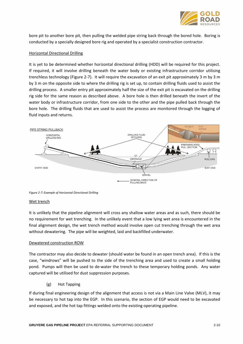
Horizontal Directional Drilling
It is yet to be determined whether horizontal directional drilling (HDD) will be required for this project.
If required, it will involve drilling beneath the water body or existing infrastructure corridor utilising
trenchless technology (Figure 2-7). It will require the excavation of an exit pit approximately 3 m by 3 m
by 3 m on the opposite side to where the drilling rig is set up, to contain drilling fluids used to assist the
drilling process. A smaller entry pit approximately half the size of the exit pit is excavated on the drilling
rig side for the same reason as described above. A bore hole is then drilled beneath the invert of the
water body or infrastructure corridor, from one side to the other and the pipe pulled back through the
bore hole. The drilling fluids that are used to assist the process are monitored through the logging of
fluid inputs and returns.
Figure 2-7: Example of Horizontal Directional Drilling
Wet trench
It is unlikely that the pipeline alignment will cross any shallow water areas and as such, there should be
no requirement for wet trenching. In the unlikely event that a low lying wet area is encountered in the
final alignment design, the wet trench method would involve open cut trenching through the wet area
without dewatering. The pipe will be weighted, laid and backfilled underwater.
Dewatered construction ROW
The contractor may also decide to dewater (should water be found in an open trench area). If this is the
case, “windrows” will be pushed to the side of the trenching area and used to create a small holding
pond. Pumps will then be used to de‐water the trench to these temporary holding ponds. Any water
captured will be utilised for dust suppression purposes.
Hot Tapping (g)
If during final engineering design of the alignment that access is not via a Main Line Valve (MLV), it may
be necessary to hot tap into the EGP. In this scenario, the section of EGP would need to be excavated
and exposed, and the hot tap fittings welded onto the existing operating pipeline.

GRUYERE GAS PIPELINE PROJECT EPA REFERRAL SUPPORTING DOCUMENT 2-11
Hot tapping is the process of drilling a hole into the operating pipe. Once the hot tap fitting has been
installed onto the pipe, a valve is installed onto the fitting and a hot tap machine is installed onto the
valve. The valve is opened allowing access to the top of the pipe and the inside of the machine is
pressurised to the same pressure as the pipeline. Inside the hot tap machine is a whole saw that is
rotated and slowly lowered onto the pipe. A pilot hole in the pipe is drilled first and wires extend
through the hole to ensure the steel disc to be removed (coupon) does not fall into the pipe. The hole
saw cuts into the pipe and completely removes the coupon. The saw is moved back into the machine
and the valve closed, sealing the pipe. The gas inside the machine can then be vented off and the
machine safely removed.
Pipe Assembly (h)
Pipe will be delivered to the construction ROW and laid out end‐to‐end alongside the trench. The pipes
are anticipated to be 18 m long and will be placed on raised timber skids or sandbags to protect the pipe
from damage, and allow it to be welded into continuous lengths (pipe strings). Gaps will be provided for
access.
Bending may be required to enable the pipe to conform to topographic conditions. Pipe may either be
‘cold bent’ in the field using hydraulic bending equipment or manufactured by applying heat in a factory
to produce the desired shape.
Pipe segments will be welded into continuous lengths before being laid in the trench. Welded joints will
be x‐ray tested to ensure compliance with AS 2885.2 Pipelines‐Gas and Liquid Petroleum‐Welding (AS
2012a), garnet blasted to remove surface scale and rust and then coated with a high build epoxy (HBE)
to provide a continuous external coating to prevent corrosion.
Once welded, the pipe strings will be placed into the trench by side‐boom tractors (or equivalent).
Bedding and padding sand will be placed around the pipe to provide protection from sharp objects
damaging the pipe coating. This will consist of fine material sourced from the trench material, wherever
possible. If this is not possible, it is anticipated that sand will be obtained from local borrow pits on Gold
Road tenure.
Dewatering (i)
Prior to lowering‐in, it may be necessary to dewater the trench if water is present. Any water will be
utilised for dust suppression purposes.
Testing (j)
The entire pipeline will be hydrostatically tested in accordance with the Australian Standard (AS2885.5)
(AS 2012b) to verify the integrity of the pipeline. Prior to hydrostatic testing, the interior of the pipeline
will be pre‐cleaned to remove weld debris, dust and surface scale. Once full of water, the pipeline will
be pressurised for an extended period (strength test). The pressure (125%) is then lowered and held for
24 hours and monitored for pressure drops (leak detection test). Hydro‐test water is anticipated to be
sourced from a variety of options including existing sources such as Laverton and bores developed for
local existing mines. Should additional water be required, water may be obtained from new bores or
dewatering wells (if required) subject to licensing from the Department of Water (DoW).

GRUYERE GAS PIPELINE PROJECT EPA REFERRAL SUPPORTING DOCUMENT 2-12
It is expected that no chemicals (biodices etc.) will be added for hydrotesting, as the pipeline is internally
coated. However, at some locations chemicals may be needed. Where required, the water will be
treated to an appropriate standard before being discharged to the environment. Discharge will comply
with DoW requirements as set out in Water Quality Protection Note 13 (DoW 2012).
Other testing of equipment that will be undertaken onsite prior to commissioning includes:
Non Destructive Testing (NDT).
Functional testing of all manual valves.
Earthing compliance checks.
Hazardous area checks/inspections.
Continuity and point to point testing of circuits.
Backfilling (k)
The period of time that any part of the trench is left open will be minimised (typically not more than 28
days). Wherever possible, stockpiled trench spoil will be returned to the trench and compacted
following the lowering‐in of the pipe. If required, clean approved locally‐sourced fill will be imported to
make up any shortfall from soil removed. This is then covered with the stockpiled spoil, where suitable.
Topsoil removed during grading will then be re‐spread over the construction ROW and contours
reinstated.
Clean‐up and Rehabilitation (l)
Upon completion of works, temporary infrastructure, equipment, waste and other stockpiled material
(e.g., stockpiled rocky material that cannot be reused for backfill) will be removed from the site. Waste
will be disposed of at the appropriate class landfill facility.
Rehabilitation of the construction ROW will aim to reinstate contours, minimise the potential for
erosion, minimise any impact on drainage patterns, minimise weed establishment, minimise the visual
impact of the pipeline installation, assist vegetative regrowth and minimise adverse impacts of the
pipeline on the existing environment.
Rehabilitation will involve re‐spreading of the stockpiled topsoil and vegetation, as well as redistribution
of any mulch from cleared vegetation, over the pipeline construction ROW to facilitate vegetative
regrowth. It is noted that a line of site must be maintained and the coating of the pipeline must be
protected from damage by plant root systems, which may require selective removal of vegetation
during the operation and maintenance phase of the project.
Revegetation of the construction ROW will be based on specialist advice and consultation with
stakeholders. Landholder’s specific requirements and requests will be identified, conditions will be
negotiated, and contact will be maintained with the landholder during construction activities. The
entire disturbed area of the construction ROW will be subject to weed monitoring, and control
programmes if required, following construction (as a part of ongoing pipeline operations). Sign posts
designating the location of the pipeline will be installed.

GRUYERE GAS PIPELINE PROJECT EPA REFERRAL SUPPORTING DOCUMENT 2-13
Commissioning (m)
Commissioning of the GGPP will be undertaken as per a project specific commissioning plan. An
overview of works undertaken during the commissioning phase of the project is as follows:
Pre‐testing of all mechanical and electrical equipment and instrumentation.
Commissioning of communications and control systems prior to introduction of gas.
Progressive introduction of gas, commissioning each item of equipment sequentially until the
whole system is capable of operating as a unit.
Handover to the relevant operations section of the gas transportation provider.
Additional requirements (n)
As the GGPP is some 220 km in length, the construction workforce is likely to be split with one team
commencing construction from the Laverton end, and the other starting at the Gruyere Gold Project
end. Accommodation for the construction teams will be available at existing facilities both in Laverton
and Gruyere Gold Project. A temporary construction camp may also be required at the mid-way point if
logistics and schedule constraints are encountered. The temporary construction camp will be located
within the Miscellaneous Licence area. The temporary construction camp site will be selected with the
following considerations in mind:
Preferred location within an area previously surveyed for heritage values so that any heritage
sites can be avoided.
Preferred location avoiding conservation significant vegetation/habitat where practicable.
Preferred location adjacent to the existing White Cliffs Road so that new road construction
(and associated environmental aspects) can be avoided.
Minimising impacts on surrounding land use.
Preferred location where existing access rights are in place.
The camp will comprise a ground surface area of approximately five ha and be purpose-designed to
accommodate up to 200 workers during peak construction. The camp will be complete with auxiliary
services such as power, communications, water, ablutions and kitchen facilities.
The camp facility will be designed and installed in accordance with the following requirements:
Wind ratings.
Health Department standards.
Local Authority planning requirements.
AS/NZS 3000:2007 – Electrical Installations (known as the Australian/New Zealand Wiring
Rules).
DFES – Built Environments Administration standards.
Water will be required for various uses at the temporary accommodation camp, dust suppression and
hydro‐testing. The following volumes of water are anticipated to be required:
GRUYERE GAS PIPELINE PROJECT EPA REFERRAL SUPPORTING DOCUMENT 2-14
Camp/ Potable water = 80 kL/day (400 L per person per day).
Dust suppression (untreated bore water): 200 kL/day.
Hydro testing = 1,500 kL.
The source of the water is yet to be determined, however, the following or combinations of all are being
explored:
Mine void water.
Established bores:
On intersected pastoral properties.
Belonging to the Shire.
Associated with adjacent mining operations (such as Granny Smith and Gruyere).
The drilling of new bores in suitable locations.
Any groundwater abstraction will be carried out in accordance with appropriate DoW licenses.
Above Ground Facilities (o)
Above ground facilities will include the off‐take, delivery/meter station and main line valve. Site civil
works at these facilities will include:
Pad construction.
Minor excavations for slab placement, control hut and meter and filter skids.
Pouring and placement of concrete slabs.
Installation of underground conduits and earth cable to the new skids.
Erection of site security fencing.
Upon completion of construction, it is expected that aggregate will be laid over ground surface areas
within 2 m of above-ground equipment, to prevent vegetative regrowth.
In addition, the following work will be required at the meter station sites:
Mechanical works include:
Assembly of equipment and lifting into position as per civil and mechanical design.
Installation of free standing equipment and structural steel work for pipe racks, pipe supports
and cable tray supports.
Installation of interconnected piping and cable tray.
Installation of instrument air and gas utility lines.
Electrical works include:
Installation of electrical power distribution and control components, cable trays and
underground conduits.

GRUYERE GAS PIPELINE PROJECT EPA REFERRAL SUPPORTING DOCUMENT 2-15
Installation of power and control cables between equipment and Remote Terminal Unit (RTU)
hut.
Loop checking, point to point and functional checking.


