369
2016 SPIDER OWNER’S MANUAL

2 0 1 6
20
16
4C
SP
IDE
R
SPIDERThird Edition
Printed in U.S.A.
©2016 FCA US LLC. All Rights Reserved.ALFA ROMEO is a registered trademark ofFCA Group Marketing S.p.A., used with permission.
16SPDR-126-AC OW N E R ’ S M A N U A L

VEHICLES SOLD IN CANADAWith respect to any Vehicles Sold in Canada, the name FCAUS LLC shall be deemed to be deleted and the name FCACanada Inc. used in substitution therefore.
DRIVING AND ALCOHOLDrunken driving is one of the most frequent causes ofaccidents.Your driving ability can be seriously impaired with bloodalcohol levels far below the legal minimum. If you aredrinking, don’t drive. Ride with a designated non-drinking driver, call a cab, a friend, or use public trans-portation.
WARNING!
Driving after drinking can lead to an accident.Your perceptions are less sharp, your reflexes areslower, and your judgment is impaired when youhave been drinking. Never drink and then drive.
This manual illustrates and describes the operation offeatures and equipment that are either standard or op-tional on this vehicle. This manual may also include adescription of features and equipment that are no longeravailable or were not ordered on this vehicle. Pleasedisregard any features and equipment described in thismanual that are not on this vehicle.
FCA US LLC reserves the right to make changes in designand specifications, and/or make additions to or improve-ments to its products without imposing any obligationupon itself to install them on products previously manu-factured.
Copyright © 2016 FCA US LLC
TABLE OF CONTENTSSECTION PAGE
1 INTRODUCTION . . . . . . . . . . . . . . . . . . . . . . . . . . . . . . . . . . . . . . . . . . . . . . . . . . . . . . . . . . . . . . . 3
2 THINGS TO KNOW BEFORE STARTING YOUR VEHICLE . . . . . . . . . . . . . . . . . . . . . . . . . . . . . . . . . . 9
3 UNDERSTANDING THE FEATURES OF YOUR VEHICLE . . . . . . . . . . . . . . . . . . . . . . . . . . . . . . . . . . 73
4 UNDERSTANDING YOUR INSTRUMENT PANEL . . . . . . . . . . . . . . . . . . . . . . . . . . . . . . . . . . . . . . . 117
5 STARTING AND OPERATING . . . . . . . . . . . . . . . . . . . . . . . . . . . . . . . . . . . . . . . . . . . . . . . . . . . . 171
6 WHAT TO DO IN EMERGENCIES . . . . . . . . . . . . . . . . . . . . . . . . . . . . . . . . . . . . . . . . . . . . . . . . . . 245
7 MAINTAINING YOUR VEHICLE . . . . . . . . . . . . . . . . . . . . . . . . . . . . . . . . . . . . . . . . . . . . . . . . . . . 263
8 MAINTENANCE SCHEDULES . . . . . . . . . . . . . . . . . . . . . . . . . . . . . . . . . . . . . . . . . . . . . . . . . . . . 329
9 IF YOU NEED CONSUMER ASSISTANCE . . . . . . . . . . . . . . . . . . . . . . . . . . . . . . . . . . . . . . . . . . . . 341
10 INDEX . . . . . . . . . . . . . . . . . . . . . . . . . . . . . . . . . . . . . . . . . . . . . . . . . . . . . . . . . . . . . . . . . . . . . 351
1
2
3
4
5
6
7
8
9
10

INTRODUCTION
CONTENTS� INTRODUCTION . . . . . . . . . . . . . . . . . . . . . . . .4
� HOW TO USE THIS MANUAL . . . . . . . . . . . . . .5
� WARNINGS AND CAUTIONS . . . . . . . . . . . . . .7
� VEHICLE IDENTIFICATION NUMBER . . . . . . . .7
� VEHICLE MODIFICATIONS/ALTERATIONS . . . .8
1
INTRODUCTION
Congratulations on selecting your new vehicle. Be as-sured that it represents precision workmanship, distinc-tive styling, and high quality - all essentials that aretraditional to our vehicles.
This Owner’s Manual has been prepared with the assis-tance of service and engineering specialists to acquaintyou with the operation and maintenance of your vehicle.It is supplemented by Warranty Information, and variouscustomer-oriented documents. Please take the time toread these publications carefully. Following the instruc-tions and recommendations in this manual will helpassure safe and enjoyable operation of your vehicle.
The enclosed Warranty Information lists the services thatFCA US LLC offers to its customers:
• The Warranty with terms and conditions for maintain-ing its validity
• The range of additional services available to FCA USLLC customers
NOTE: After reviewing the owner information, itshould be stored in the vehicle for convenient referenc-ing and remain with the vehicle when sold.
When it comes to service, remember that your authorizeddealer knows your vehicle best, has factory-trained tech-nicians and genuine MOPAR® parts, and cares aboutyour satisfaction.
4 INTRODUCTION
HOW TO USE THIS MANUAL
Consult the Table of Contents to determine which sectioncontains the information you desire.
Since the specification of your vehicle depends on theitems of equipment ordered, certain descriptions andillustrations may differ from your vehicle’s equipment.
The detailed index at the back of this Owner’s Manualcontains a complete listing of all subjects.
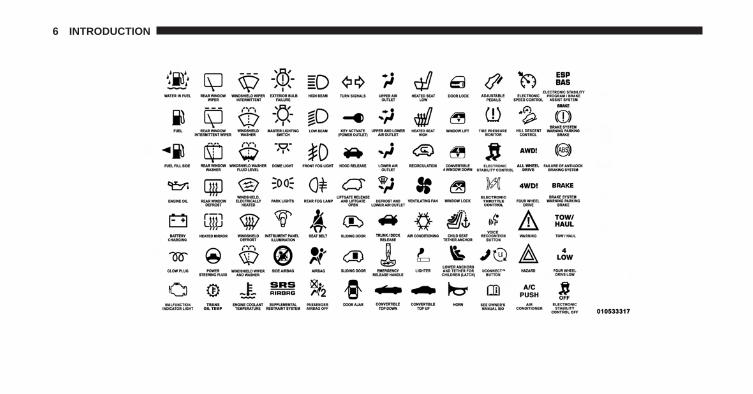
Consult the following table for a description of thesymbols that may be used on your vehicle or throughoutthis Owner’s Manual:
1
INTRODUCTION 5
6 INTRODUCTION
WARNINGS AND CAUTIONS
This Owner’s Manual contains WARNINGS againstoperating procedures that could result in a collision,bodily injury and/or death. It also contains CAUTIONSagainst procedures that could result in damage to yourvehicle. If you do not read this entire Owner’s Manual,you may miss important information. Observe all Warn-ings and Cautions.
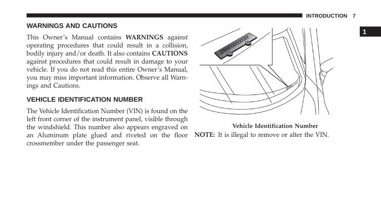
VEHICLE IDENTIFICATION NUMBER
The Vehicle Identification Number (VIN) is found on theleft front corner of the instrument panel, visible throughthe windshield. This number also appears engraved onan Aluminum plate glued and riveted on the floorcrossmember under the passenger seat.
NOTE: It is illegal to remove or alter the VIN.Vehicle Identification Number
1
INTRODUCTION 7
VEHICLE MODIFICATIONS/ALTERATIONS
WARNING!
Any modifications or alterations to this vehicle couldseriously affect its roadworthiness and safety andmay lead to a collision resulting in serious injury ordeath.
8 INTRODUCTION
THINGS TO KNOW BEFORE STARTING YOUR VEHICLE
CONTENTS� A WORD ABOUT YOUR KEYS . . . . . . . . . . . . .11
▫ Ignition Key Removal . . . . . . . . . . . . . . . . . . .12
▫ Locking Doors With A Key . . . . . . . . . . . . . . .13
▫ Key-In-Ignition Reminder . . . . . . . . . . . . . . . .14
� SENTRY KEY . . . . . . . . . . . . . . . . . . . . . . . . . .14
▫ Replacement Keys . . . . . . . . . . . . . . . . . . . . .15
▫ General Information . . . . . . . . . . . . . . . . . . . .15
� VEHICLE SECURITY ALARM SYSTEM —IF EQUIPPED . . . . . . . . . . . . . . . . . . . . . . . . . .15
▫ To Arm The System . . . . . . . . . . . . . . . . . . . .16
▫ To Disarm The System . . . . . . . . . . . . . . . . . .17
� ILLUMINATED ENTRY . . . . . . . . . . . . . . . . . . .18
� REMOTE KEYLESS ENTRY (RKE) —IF EQUIPPED . . . . . . . . . . . . . . . . . . . . . . . . . .18
▫ To Unlock The Doors . . . . . . . . . . . . . . . . . . .19
▫ To Lock The Doors . . . . . . . . . . . . . . . . . . . . .19
▫ Transmitter Battery Replacement . . . . . . . . . . .20
▫ General Information . . . . . . . . . . . . . . . . . . . .22
� DOOR LOCKS . . . . . . . . . . . . . . . . . . . . . . . . .22
▫ Central Door Locking/Unlocking . . . . . . . . . . .22
2
▫ Locking/Unlocking Doors From The Inside . . .24
▫ Emergency Door Locking Device . . . . . . . . . . .24
▫ Door Opening/Closing Mechanism Reset . . . . .25
� WINDOWS . . . . . . . . . . . . . . . . . . . . . . . . . . .26
▫ Power Windows . . . . . . . . . . . . . . . . . . . . . . .26
� DECKLID . . . . . . . . . . . . . . . . . . . . . . . . . . . . .28
� OCCUPANT RESTRAINT SYSTEMS . . . . . . . . . .30
▫ Important Safety Precautions . . . . . . . . . . . . . .31
▫ Seat Belt Systems . . . . . . . . . . . . . . . . . . . . . .32
▫ Supplemental Restraint System (SRS) . . . . . . . .43
▫ Child Restraints . . . . . . . . . . . . . . . . . . . . . . .57
▫ Transporting Pets . . . . . . . . . . . . . . . . . . . . . .67
� ENGINE BREAK-IN RECOMMENDATIONS . . . .68
� SAFETY TIPS . . . . . . . . . . . . . . . . . . . . . . . . . .69
▫ Transporting Passengers . . . . . . . . . . . . . . . . .69
▫ Exhaust Gas . . . . . . . . . . . . . . . . . . . . . . . . .69
▫ Safety Checks You Should Make InsideThe Vehicle . . . . . . . . . . . . . . . . . . . . . . . . . .70
▫ Periodic Safety Checks You Should MakeOutside The Vehicle . . . . . . . . . . . . . . . . . . . .71
10 THINGS TO KNOW BEFORE STARTING YOUR VEHICLE
A WORD ABOUT YOUR KEYS
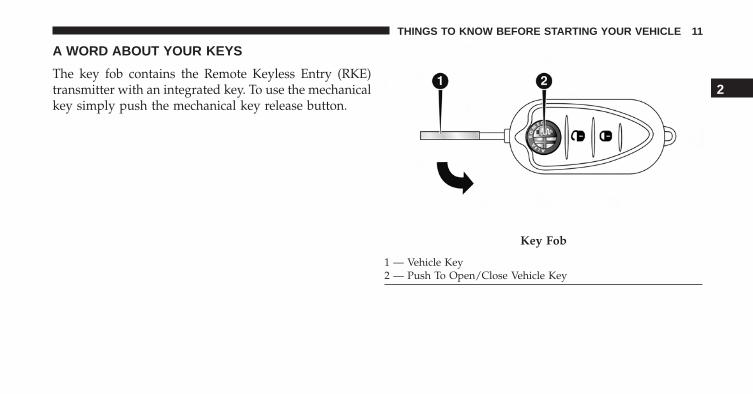
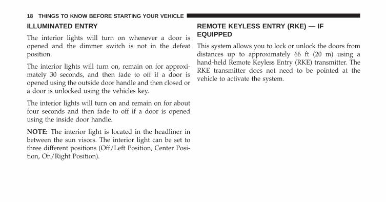
The key fob contains the Remote Keyless Entry (RKE)transmitter with an integrated key. To use the mechanicalkey simply push the mechanical key release button.
Key Fob
1 — Vehicle Key2 — Push To Open/Close Vehicle Key
2
THINGS TO KNOW BEFORE STARTING YOUR VEHICLE 11
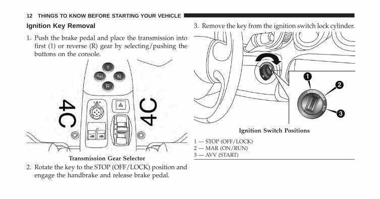
Ignition Key Removal
1. Push the brake pedal and place the transmission intofirst (1) or reverse (R) gear by selecting/pushing thebuttons on the console.
2. Rotate the key to the STOP (OFF/LOCK) position andengage the handbrake and release brake pedal.
3. Remove the key from the ignition switch lock cylinder.
Transmission Gear Selector
Ignition Switch Positions
1 — STOP (OFF/LOCK)2 — MAR (ON/RUN)3 — AVV (START)
12 THINGS TO KNOW BEFORE STARTING YOUR VEHICLE
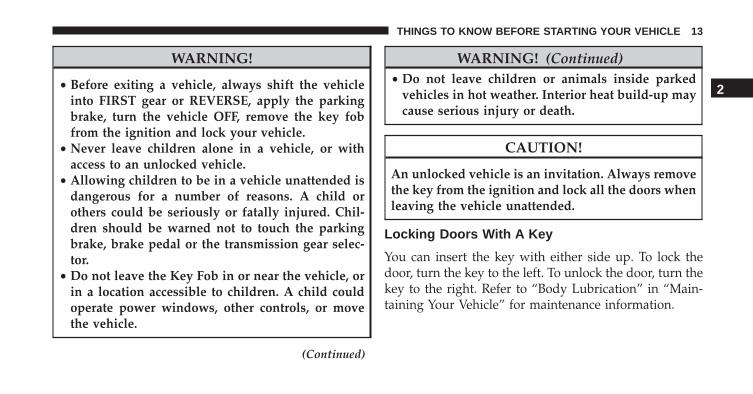
WARNING!
• Before exiting a vehicle, always shift the vehicleinto FIRST gear or REVERSE, apply the parkingbrake, turn the vehicle OFF, remove the key fobfrom the ignition and lock your vehicle.
• Never leave children alone in a vehicle, or withaccess to an unlocked vehicle.
• Allowing children to be in a vehicle unattended isdangerous for a number of reasons. A child orothers could be seriously or fatally injured. Chil-dren should be warned not to touch the parkingbrake, brake pedal or the transmission gear selec-tor.
• Do not leave the Key Fob in or near the vehicle, orin a location accessible to children. A child couldoperate power windows, other controls, or movethe vehicle.
(Continued)
WARNING! (Continued)• Do not leave children or animals inside parked
vehicles in hot weather. Interior heat build-up maycause serious injury or death.
CAUTION!
An unlocked vehicle is an invitation. Always removethe key from the ignition and lock all the doors whenleaving the vehicle unattended.
Locking Doors With A Key
You can insert the key with either side up. To lock thedoor, turn the key to the left. To unlock the door, turn thekey to the right. Refer to “Body Lubrication” in “Main-taining Your Vehicle” for maintenance information.
2
THINGS TO KNOW BEFORE STARTING YOUR VEHICLE 13
Key-In-Ignition Reminder
Opening the driver’s door when the key is in the ignitionand the ignition switch position is in the STOP (OFF/LOCK) position, sounds a signal to remove the key.
SENTRY KEY
The Sentry Key Immobilizer System prevents unauthor-ized vehicle operation by disabling the engine. Thesystem does not need to be armed or activated. Operationis automatic, regardless of whether the vehicle is lockedor unlocked.
The system uses ignition keys which have an embeddedelectronic chip (transponder) to prevent unauthorizedvehicle operation. Therefore, only keys that are pro-grammed to the vehicle can be used to start and operatethe vehicle.
NOTE: A key which has not been programmed is alsoconsidered an invalid key, even if it is cut to fit theignition switch lock cylinder for that vehicle.
If the Vehicle Security Light is on after the key is turnedto the ON/RUN position, it indicates that there is aproblem with the electronics.
CAUTION!
• Always remove the Sentry Key from the vehicleand lock all doors when leaving the vehicle unat-tended.
• The Sentry Key Immobilizer system is not compat-ible with some aftermarket remote starting sys-tems. Use of these systems may result in vehiclestarting problems and loss of security protection.
All of the keys provided with your new vehicle havebeen programmed to the vehicle electronics.
14 THINGS TO KNOW BEFORE STARTING YOUR VEHICLE
Replacement Keys
NOTE: Only keys that have been programmed to thevehicle electronics can be used to start the vehicle. Oncea Sentry Key has been programmed to a vehicle, it cannotbe programmed to any other vehicle.
NOTE: When having the Sentry Key Immobilizer Sys-tem serviced, bring all vehicle keys with you to anauthorized dealer.
General Information
The following regulatory statement applies to all RadioFrequency (RF) devices equipped in this vehicle:
This device complies with Part 15 of the FCC Rules andwith Industry Canada license-exempt RSS standard(s).Operation is subject to the following two conditions:1. This device may not cause harmful interference, and2. This device must accept any interference received, in-
cluding interference that may cause undesired operation.
NOTE: Changes or modifications not expressly approvedby the party responsible for compliance could void theuser’s authority to operate the equipment.
VEHICLE SECURITY ALARM SYSTEM — IFEQUIPPED
The Vehicle Security Alarm monitors the doors anddecklid for unauthorized entry and the ignition forunauthorized operation. If something triggers the alarm,the Vehicle Security Alarm will prevent the vehicle fromstarting. It will also emit an acoustic signal and flash thepark lights, and taillights.
Operation
The alarm activates in the following cases:
1. Wrongful opening of one of the doors or the decklid(perimeter protection);
2
THINGS TO KNOW BEFORE STARTING YOUR VEHICLE 15
2. Wrongful operation of the ignition switch (key turnedto MAR ON/RUN);
3. Cutting of the battery leads;
4. Anomalous lifting/tilting of the car.
Operation of the alarm is indicated by an acoustic andvisual signal (flashing of the direction indicators forseveral seconds). The alarm activation modes may varyaccording to the market. There is a maximum number ofacoustic/visual cycles. When this is reached the systemreturns to normal operation.
NOTE:
• The engine locking function is guaranteed by the AlfaRomeo CODE, which is automatically activated whenthe key is extracted from the ignition switch.
• The alarm is adapted to meet requirements in variouscountries.
To Arm The System
With the doors and decklid closed and the ignition keyeither turned to STOP (OFF/LOCK) or removed, pointthe key towards the vehicle then push and release thelock button.
The system emits a visual signal and activates doorlocking.
A self-diagnosis stage lasting approximately 30 secondsprecedes the activation of the alarm. During the self-diagnosis, the vehicle security light flashes in the instru-ment panel at a frequency of about one flash per second.
After the self-diagnosis stage, the vehicle security lightflashes at a lower frequency (approximately one flashevery three seconds).
If, after the alarm is switched on, a second visual signalemit via the vehicle security light in the instrument panel,wait about four seconds and switch off the alarm by
16 THINGS TO KNOW BEFORE STARTING YOUR VEHICLE
pushing the lock button, check that the doors and decklidare closed correctly and then reactivate the system bypushing the unlock button.
If the alarm emits a visual signal even when the doorsand decklid are closed correctly, a system malfunctionhas occurred: in this case, contact a authorized vehicleDealership.
To Disarm The System
Deactivation
Push the unlock button.
The following operations are performed:
• Two brief flashes of the direction indicators.
• Unlocking of the doors.
NOTE:
• If the central door locking system is released using themetal insert of the key, the alarm is not disabled.
• In the event of accidental activation of the alarm, or inany case to interrupt the visual signal cycle whenactivated, it is possible to push the unlock button orturn the ignition key to MAR (ON/RUN) for at leastfive seconds, after which the system will deactivate.
Disarming
To completely disable the alarm (e.g. during a lengthyperiod of vehicle inactivity), lock the vehicle by turningthe metal insert of the key in the door lock.
NOTE: If the batteries of the key fob run out or there is afault in the system, the alarm can be switched off byinserting the key in the ignition switch and turning it toMAR (ON/RUN).
2
THINGS TO KNOW BEFORE STARTING YOUR VEHICLE 17
ILLUMINATED ENTRY
The interior lights will turn on whenever a door isopened and the dimmer switch is not in the defeatposition.
The interior lights will turn on, remain on for approxi-mately 30 seconds, and then fade to off if a door isopened using the outside door handle and then closed ora door is unlocked using the vehicles key.
The interior lights will turn on and remain on for aboutfour seconds and then fade to off if a door is openedusing the inside door handle.
NOTE: The interior light is located in the headliner inbetween the sun visors. The interior light can be set tothree different positions (Off/Left Position, Center Posi-tion, On/Right Position).
REMOTE KEYLESS ENTRY (RKE) — IFEQUIPPED
This system allows you to lock or unlock the doors fromdistances up to approximately 66 ft (20 m) using ahand-held Remote Keyless Entry (RKE) transmitter. TheRKE transmitter does not need to be pointed at thevehicle to activate the system.
18 THINGS TO KNOW BEFORE STARTING YOUR VEHICLE
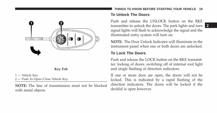
NOTE: The line of transmission must not be blockedwith metal objects.
To Unlock The Doors
Push and release the UNLOCK button on the RKEtransmitter to unlock the doors. The park lights and turnsignal lights will flash to acknowledge the signal and theilluminated entry system will turn on.
NOTE: The Door Unlock Indicator will illuminate in theinstrument panel when one or both doors are unlocked.
To Lock The Doors
Push and release the LOCK button on the RKE transmit-ter: locking of doors, switching off of internal roof lightand single flashing of direction indicators.
If one or more door are open, the doors will not belocked. This is indicated by a rapid flashing of thedirection indicators. The doors will be locked if thedecklid is open however.
Key Fob
1 — Vehicle Key2 — Push To Open/Close Vehicle Key
2
THINGS TO KNOW BEFORE STARTING YOUR VEHICLE 19
When a speed of more than 12 mph (20 km/h) is reached,the doors will be locked automatically if the Autoclosefunction was selected. Refer to “Electronic Vehicle Infor-mation Center (EVIC)” in “Understanding Your Instru-ment Panel” for further information.
When the doors are locked from outside the vehicle (usingthe remote control), the door lock indicator will illuminatefor a few seconds and then start flashing (deterrent function).
Transmitter Battery Replacement
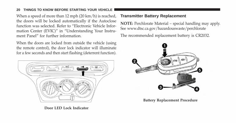
NOTE: Perchlorate Material – special handling may apply.See www.dtsc.ca.gov/hazardouswaste/perchlorate
The recommended replacement battery is CR2032.
Door LED Lock Indicator
Battery Replacement Procedure
20 THINGS TO KNOW BEFORE STARTING YOUR VEHICLE
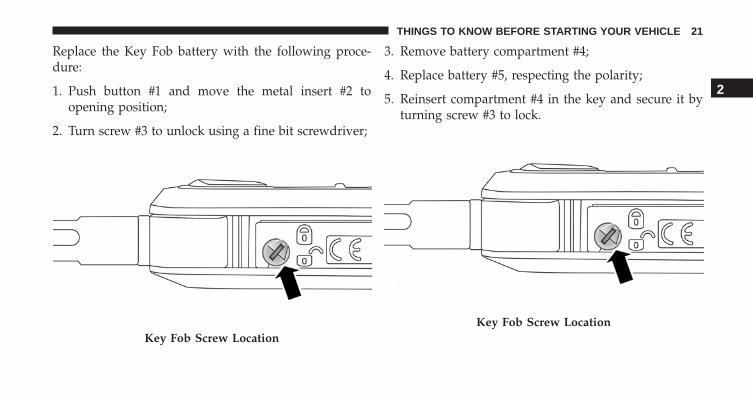
Replace the Key Fob battery with the following proce-dure:
1. Push button #1 and move the metal insert #2 toopening position;
2. Turn screw #3 to unlock using a fine bit screwdriver;
3. Remove battery compartment #4;
4. Replace battery #5, respecting the polarity;
5. Reinsert compartment #4 in the key and secure it byturning screw #3 to lock.
Key Fob Screw LocationKey Fob Screw Location
2
THINGS TO KNOW BEFORE STARTING YOUR VEHICLE 21
General Information
The following regulatory statement applies to all RadioFrequency (RF) devices equipped in this vehicle:
This device complies with Part 15 of the FCC Rules andwith Industry Canada license-exempt RSS standard(s).Operation is subject to the following two conditions:
1. This device may not cause harmful interference, and
2. This device must accept any interference received,including interference that may cause undesired op-eration.
NOTE: Changes or modifications not expressly approvedby the party responsible for compliance could void theuser’s authority to operate the equipment.
DOOR LOCKS
Central Door Locking/Unlocking
Locking Doors From The Outside
With the doors closed, push the lock button on the keyfob or turn the metal insert (located inside the key fob) inthe door lock.
The Door Lock LED Indicator button will illuminateto indicate that the doors have locked.
22 THINGS TO KNOW BEFORE STARTING YOUR VEHICLE
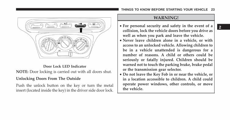
NOTE: Door locking is carried out with all doors shut.
Unlocking Doors From The Outside
Push the unlock button on the key or turn the metalinsert (located inside the key) in the driver side door lock.
WARNING!
• For personal security and safety in the event of acollision, lock the vehicle doors before you drive aswell as when you park and leave the vehicle.
• Never leave children alone in a vehicle, or withaccess to an unlocked vehicle. Allowing children tobe in a vehicle unattended is dangerous for anumber of reasons. A child or others could beseriously or fatally injured. Children should bewarned not to touch the parking brake, brake pedalor the transmission gear selector.
• Do not leave the Key Fob in or near the vehicle, orin a location accessible to children. A child couldoperate power windows, other controls, or movethe vehicle.
Door Lock LED Indicator
2
THINGS TO KNOW BEFORE STARTING YOUR VEHICLE 23
Locking/Unlocking Doors From The Inside
Push the Lock LED Indicator button . The button hasan LED that indicates whether the doors are locked orunlocked.
Pushing the Lock LED Indicator button again cen-trally unlocks all doors and switches off the LED.
Pushing the Lock LED Indicator button again cen-trally locks all the doors. The doors will be locked onlyif all the doors are properly shut.
Once the doors have been locked using the remotecontrol or the key, it will no longer be possible to unlockthem by pushing the Lock LED Indicator button .
NOTE: In the absence of electrical power supply (blownfuse, battery disconnected, etc.), it is still possible to lockthe doors manually.
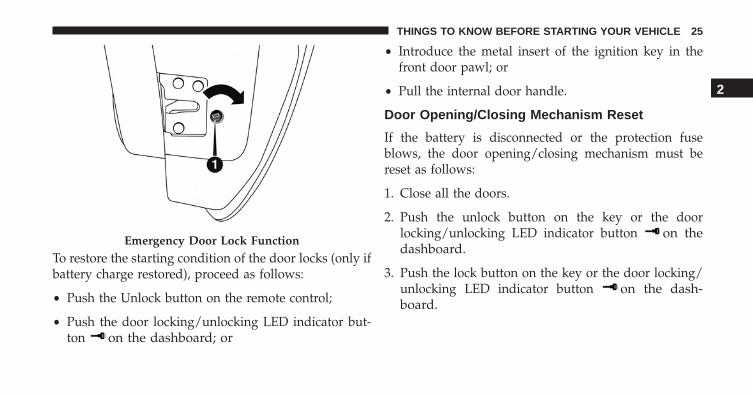
Emergency Door Locking Device
Passenger Side Door
The passenger side door has a device to lock it whenthere is no current.
To lock it, place the metal insert of the ignition key inhousing #1 and turn it clockwise.
24 THINGS TO KNOW BEFORE STARTING YOUR VEHICLE
To restore the starting condition of the door locks (only ifbattery charge restored), proceed as follows:
• Push the Unlock button on the remote control;
• Push the door locking/unlocking LED indicator but-ton on the dashboard; or
• Introduce the metal insert of the ignition key in thefront door pawl; or
• Pull the internal door handle.
Door Opening/Closing Mechanism Reset
If the battery is disconnected or the protection fuseblows, the door opening/closing mechanism must bereset as follows:
1. Close all the doors.
2. Push the unlock button on the key or the doorlocking/unlocking LED indicator button on thedashboard.
3. Push the lock button on the key or the door locking/unlocking LED indicator button on the dash-board.
Emergency Door Lock Function
2
THINGS TO KNOW BEFORE STARTING YOUR VEHICLE 25
WINDOWS
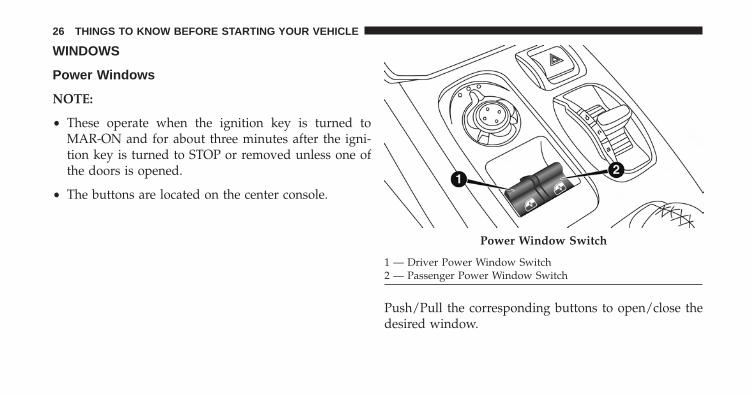
Power Windows
NOTE:
• These operate when the ignition key is turned toMAR-ON and for about three minutes after the igni-tion key is turned to STOP or removed unless one ofthe doors is opened.
• The buttons are located on the center console.
Push/Pull the corresponding buttons to open/close thedesired window.
Power Window Switch
1 — Driver Power Window Switch2 — Passenger Power Window Switch
26 THINGS TO KNOW BEFORE STARTING YOUR VEHICLE
When one of the two buttons is pushed briefly, thewindow moves in stages; if the button is held down toopen, �continuous automatic� operation is activated.
If the button is pushed again, the window will stop in itscurrent position. If the button is pushed for severalseconds, the window lowers automatically (only withignition key in MAR-ON position).
Continuous Automatic Operation
This is activated by pushing one of the two buttons forlonger than half a second. The window will stop when itis fully opened, or when the button is pushed again.
It can be used on both the driver side and passenger side,only for lowering the window.
Electric Window System Reset
After a break in power supply for the control units(battery replaced or disconnected or protective fuses for
the electric window control units replaced), the auto-matic operation of the windows must be restored.
The restoration procedure must be performed as de-scribed below with the doors closed:
1. Completely open the driver’s door window keepingthe operating button pushed for at least three secondsafter the (lower) end of travel position is reached.
2. Completely raise the driver side window and hold thebutton down for at least three seconds once the(upper) end of travel position has been reached.
3. Proceed in the same way as described in points 1 and2 for the passenger side door.
4. Make sure that the reset is correct by checking that thewindows work automatically.
2
THINGS TO KNOW BEFORE STARTING YOUR VEHICLE 27
WARNING!
Improper actuation of the power windows may bedangerous. Never leave children unattended in avehicle, and do not let children play with powerwindows. Before and during window operationmake sure no one and no object (including clothing)is in the path of the moving glass or its mechanism.Do not leave the key fob in or near the vehicle, or ina location accessible to children. Occupants, particu-larly unattended children, can become entrapped bythe windows while operating the power windowswitches. Such entrapment may result in seriousinjury or death.
DECKLID
NOTE: During normal vehicle operation, the luggagecompartment can reach temperatures above 149º F (65°C). Pay attention when transporting objects that may bedamaged at such temperatures. Do not keep aerosol cansin the vehicle: danger of explosion. Aerosol cans must notbe exposed to temperatures above 122º F (50° C).
Opening Procedure
With driver side door open, pull lever #1 located at thepoint illustrated in the figure.
28 THINGS TO KNOW BEFORE STARTING YOUR VEHICLE
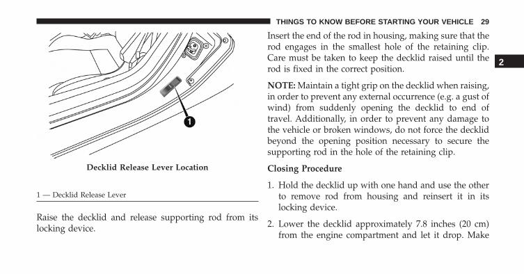
Raise the decklid and release supporting rod from itslocking device.
Insert the end of the rod in housing, making sure that therod engages in the smallest hole of the retaining clip.Care must be taken to keep the decklid raised until therod is fixed in the correct position.
NOTE: Maintain a tight grip on the decklid when raising,in order to prevent any external occurrence (e.g. a gust ofwind) from suddenly opening the decklid to end oftravel. Additionally, in order to prevent any damage tothe vehicle or broken windows, do not force the decklidbeyond the opening position necessary to secure thesupporting rod in the hole of the retaining clip.
Closing Procedure
1. Hold the decklid up with one hand and use the otherto remove rod from housing and reinsert it in itslocking device.
2. Lower the decklid approximately 7.8 inches (20 cm)from the engine compartment and let it drop. Make
Decklid Release Lever Location
1 — Decklid Release Lever
2
THINGS TO KNOW BEFORE STARTING YOUR VEHICLE 29
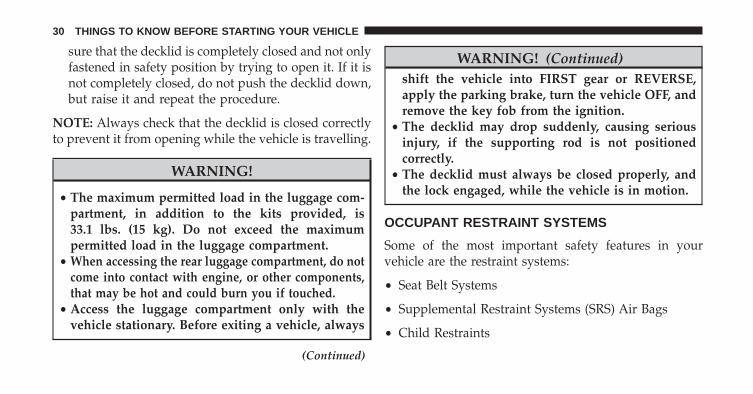
sure that the decklid is completely closed and not onlyfastened in safety position by trying to open it. If it isnot completely closed, do not push the decklid down,but raise it and repeat the procedure.
NOTE: Always check that the decklid is closed correctlyto prevent it from opening while the vehicle is travelling.
WARNING!
• The maximum permitted load in the luggage com-partment, in addition to the kits provided, is33.1 lbs. (15 kg). Do not exceed the maximumpermitted load in the luggage compartment.
• When accessing the rear luggage compartment, do notcome into contact with engine, or other components,that may be hot and could burn you if touched.
• Access the luggage compartment only with thevehicle stationary. Before exiting a vehicle, always
(Continued)
WARNING! (Continued)shift the vehicle into FIRST gear or REVERSE,apply the parking brake, turn the vehicle OFF, andremove the key fob from the ignition.
• The decklid may drop suddenly, causing seriousinjury, if the supporting rod is not positionedcorrectly.
• The decklid must always be closed properly, andthe lock engaged, while the vehicle is in motion.
OCCUPANT RESTRAINT SYSTEMS
Some of the most important safety features in yourvehicle are the restraint systems:
• Seat Belt Systems
• Supplemental Restraint Systems (SRS) Air Bags
• Child Restraints
30 THINGS TO KNOW BEFORE STARTING YOUR VEHICLE
Important Safety Precautions
Please pay close attention to the information in this section.It tells you how to use your restraint system properly, tokeep you and your passengers as safe as possible.
Here are some simple steps you can take to minimize therisk of harm from a deploying air bag:
1. Children 12 years old and under should always ridebuckled up in a vehicle with a rear seat.
2. If a child from 2 to 12 years old (not in a rear-facingchild restraint) must ride in the front passenger seat,move the seat as far back as possible and use theproper child restraint. (Refer to “Child Restraints”)
3. Children that are not big enough to wear the vehicle seatbelt properly (Refer to �Child Restraints�) should besecured in a vehicle with a rear seat in child restraints orbelt-positioning booster seats. Older children who do
not use child restraints or belt-positioning booster seatsshould ride properly buckled up in a vehicle with a rearseat.
4. Never allow children to slide the shoulder belt behindthem or under their arm.
5. You should read the instructions provided with yourchild restraint to make sure that you are using it properly.
6. All occupants should always wear their lap andshoulder belts properly.
7. The driver and front passenger seats should be movedback as far as practical to allow the Advanced FrontAir Bags room to inflate.
8. Do not lean against the door or window. If yourvehicle has side air bags, and deployment occurs, theside air bags will inflate forcefully into the spacebetween occupants and the door and occupants couldbe injured.
2
THINGS TO KNOW BEFORE STARTING YOUR VEHICLE 31
9. If the air bag system in this vehicle needs to bemodified to accommodate a disabled person, contactthe Customer Center. Phone numbers are providedunder �If You Need Assistance.�
WARNING!
• Never place a rear-facing child restraint in front ofan air bag. A deploying passenger Advanced FrontAir Bag can cause death or serious injury to a child12 years or younger, including a child in a rear-facing child restraint.
• Only use a rear-facing child restraint in a vehiclewith a rear seat.
Seat Belt Systems
Buckle up even though you are an excellent driver, evenon short trips. Someone on the road may be a poor driverand could cause a collision that includes you. This canhappen far away from home or on your own street.
Research has shown that seat belts save lives, and theycan reduce the seriousness of injuries in a collision. Someof the worst injuries happen when people are thrownfrom the vehicle. Seat belts reduce the possibility ofejection and the risk of injury caused by striking theinside of the vehicle. Everyone in a motor vehicle shouldbe belted at all times.
Driver And Passenger BeltAlert (If Equipped)
BeltAlert is a feature intended to remind the driverand outboard front seat passenger (if equipped withoutboard front passenger seat BeltAlert) to buckle
32 THINGS TO KNOW BEFORE STARTING YOUR VEHICLE
their seat belts. The Belt Alert feature is active when-ever the ignition switch is in the AVV/START orMAR/RUN position.
Initial Indication
If the driver is unbuckled when the ignition switch is firstturned to the AVV/START or MAR/RUN position, achime will signal for a few seconds. If the driver oroutboard front seat passenger (if equipped with outboardfront passenger seat BeltAlert) is unbuckled when theignition switch is first turned to the AVV/START orMAR/ RUN position the Seat Belt Reminder Light willturn on and remain on until both outboard front seatbelts are buckled. The outboard front passenger seatBeltAlert is not active when the outboard front passengerseat is unoccupied.
BeltAlert Warning Sequence
The BeltAlert warning sequence is activated when thevehicle is moving above a specified vehicle speed rangeand the driver or outboard front seat passenger is un-buckled (the outboard front passenger seat BeltAlert isnot active when the outboard front passenger seat isunoccupied). The BeltAlert warning sequence starts byblinking the Seat Belt Reminder Light and sounding anintermittent chime. Once the BeltAlert warning sequencehas completed, the Seat Belt Reminder Light will remainon until the seat belts are buckled. The BeltAlert warningsequence may repeat based on vehicle speed until thedriver and occupied outboard front seat passenger seatbelts are buckled. The driver should instruct all occu-pants to buckle their seat belts.
2
THINGS TO KNOW BEFORE STARTING YOUR VEHICLE 33
Change Of Status
If the driver or outboard front seat passenger (ifequipped with outboard front passenger seat BeltAlert)unbuckles their seat belt while the vehicle is traveling,the BeltAlert warning sequence will begin until the seatbelts are buckled again. The outboard front passengerseat BeltAlert is not active when the outboard frontpassenger seat is unoccupied. BeltAlert may be triggeredwhen an animal or heavy object is on the outboard frontpassenger seat or when the seat is folded flat (ifequipped). It is recommended that pets be restrained inthe rear seat (if equipped) in pet harnesses or pet carriersthat are secured by seat belts, and cargo is properlystowed.
BeltAlert can be activated or deactivated by your autho-rized dealer. FCA US LLC does not recommend deacti-vating BeltAlert.
NOTE: If BeltAlert has been deactivated and the driveror outboard front seat passenger is unbuckled the SeatBelt Reminder Light will turn on and remain on until thedriver and outboard front seat passenger seat belts arebuckled.
Lap/Shoulder Belts
All seating positions in your vehicle are equipped withlap/shoulder belts.
The seat belt webbing retractor will lock only during verysudden stops or collisions. This feature allows the shoul-der part of the seat belt to move freely with you undernormal conditions. However, in a collision the seat beltwill lock and reduce your risk of striking the inside of thevehicle or being thrown out of the vehicle.
34 THINGS TO KNOW BEFORE STARTING YOUR VEHICLE
WARNING!
• Relying on the air bags alone could lead to moresevere injuries in a collision. The air bags workwith your seat belt to restrain you properly. Insome collisions, the air bags won’t deploy at all.Always wear your seat belt even though you haveair bags.
• In a collision, you and your passengers can suffermuch greater injuries if you are not properly buck-led up. You can strike the interior of your vehicle orother passengers, or you can be thrown out of thevehicle. Always be sure you and others in yourvehicle are buckled up properly.
• It is dangerous to ride in a cargo area, inside oroutside of a vehicle. In a collision, people riding inthese areas are more likely to be seriously injuredor killed.
(Continued)
WARNING! (Continued)• Do not allow people to ride in any area of your
vehicle that is not equipped with seats and seatbelts.
• Be sure everyone in your vehicle is in a seat andusing a seat belt properly.
• Wearing your seat belt incorrectly could make yourinjuries in a collision much worse. You mightsuffer internal injuries, or you could even slide outof the seat belt. Follow these instructions to wearyour seat belt safely and to keep your passengerssafe, too.
• Two people should never be belted into a singleseat belt. People belted together can crash into oneanother in a collision, hurting one another badly.Never use a lap/shoulder belt or a lap belt for morethan one person, no matter what their size.
(Continued)
2
THINGS TO KNOW BEFORE STARTING YOUR VEHICLE 35
WARNING! (Continued)• A lap belt worn too high can increase the risk of
injury in a collision. The seat belt forces won’t be atthe strong hip and pelvic bones, but across yourabdomen. Always wear the lap part of your seatbelt as low as possible and keep it snug.
• A twisted seat belt may not protect you properly. Ina collision, it could even cut into you. Be sure theseat belt is flat against your body, without twists. Ifyou can’t straighten a seat belt in your vehicle, takeit to your authorized dealer immediately and haveit fixed.
• A seat belt that is buckled into the wrong bucklewill not protect you properly. The lap portion couldride too high on your body, possibly causing inter-nal injuries. Always buckle your seat belt into thebuckle nearest you.
(Continued)
WARNING! (Continued)• A seat belt that is too loose will not protect you
properly. In a sudden stop, you could move too farforward, increasing the possibility of injury. Wearyour seat belt snugly.
• A seat belt that is worn under your arm is dangerous.Your body could strike the inside surfaces of thevehicle in a collision, increasing head and neck injury.A seat belt worn under the arm can cause internalinjuries. Ribs aren’t as strong as shoulder bones. Wearthe seat belt over your shoulder so that your strongestbones will take the force in a collision.
• A shoulder belt placed behind you will not protectyou from injury during a collision. You are morelikely to hit your head in a collision if you do notwear your shoulder belt. The lap and shoulder beltare meant to be used together.
(Continued)
36 THINGS TO KNOW BEFORE STARTING YOUR VEHICLE
WARNING! (Continued)• A frayed or torn seat belt could rip apart in a
collision and leave you with no protection. Inspectthe seat belt system periodically, checking for cuts,frays, or loose parts. Damaged parts must be re-placed immediately. Do not disassemble or modifythe seat belt system. Seat belt assemblies must bereplaced after a collision.
Lap/Shoulder Belt Operating Instructions
1. Enter the vehicle and close the door. Sit back andadjust the seat.
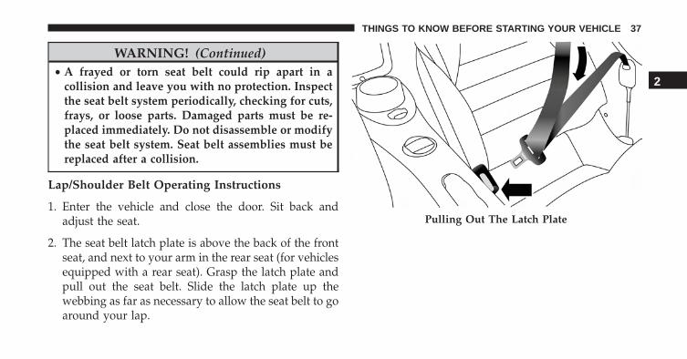
2. The seat belt latch plate is above the back of the frontseat, and next to your arm in the rear seat (for vehiclesequipped with a rear seat). Grasp the latch plate andpull out the seat belt. Slide the latch plate up thewebbing as far as necessary to allow the seat belt to goaround your lap.
Pulling Out The Latch Plate
2
THINGS TO KNOW BEFORE STARTING YOUR VEHICLE 37
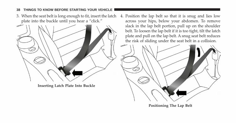
3. When the seat belt is long enough to fit, insert the latchplate into the buckle until you hear a “click.”
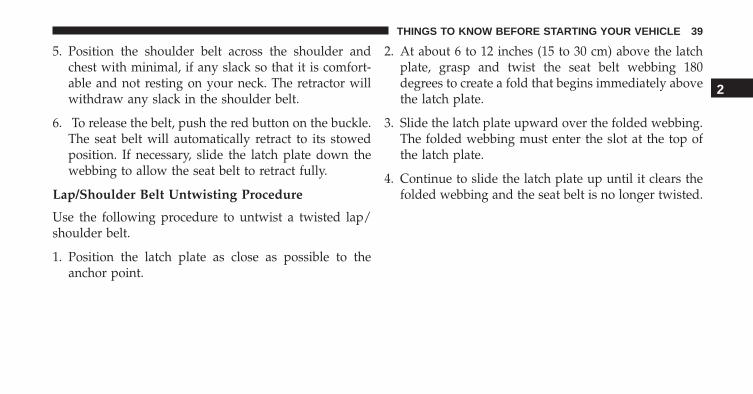
4. Position the lap belt so that it is snug and lies lowacross your hips, below your abdomen. To removeslack in the lap belt portion, pull up on the shoulderbelt. To loosen the lap belt if it is too tight, tilt the latchplate and pull on the lap belt. A snug seat belt reducesthe risk of sliding under the seat belt in a collision.
Inserting Latch Plate Into Buckle
Positioning The Lap Belt
38 THINGS TO KNOW BEFORE STARTING YOUR VEHICLE
5. Position the shoulder belt across the shoulder andchest with minimal, if any slack so that it is comfort-able and not resting on your neck. The retractor willwithdraw any slack in the shoulder belt.
6. To release the belt, push the red button on the buckle.The seat belt will automatically retract to its stowedposition. If necessary, slide the latch plate down thewebbing to allow the seat belt to retract fully.
Lap/Shoulder Belt Untwisting Procedure
Use the following procedure to untwist a twisted lap/shoulder belt.
1. Position the latch plate as close as possible to theanchor point.
2. At about 6 to 12 inches (15 to 30 cm) above the latchplate, grasp and twist the seat belt webbing 180degrees to create a fold that begins immediately abovethe latch plate.
3. Slide the latch plate upward over the folded webbing.The folded webbing must enter the slot at the top ofthe latch plate.
4. Continue to slide the latch plate up until it clears thefolded webbing and the seat belt is no longer twisted.
2
THINGS TO KNOW BEFORE STARTING YOUR VEHICLE 39
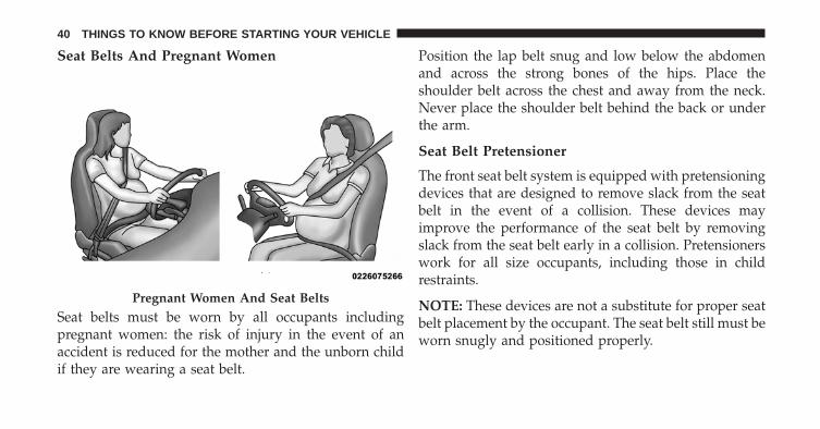
Seat Belts And Pregnant Women
Seat belts must be worn by all occupants includingpregnant women: the risk of injury in the event of anaccident is reduced for the mother and the unborn childif they are wearing a seat belt.
Position the lap belt snug and low below the abdomenand across the strong bones of the hips. Place theshoulder belt across the chest and away from the neck.Never place the shoulder belt behind the back or underthe arm.
Seat Belt Pretensioner
The front seat belt system is equipped with pretensioningdevices that are designed to remove slack from the seatbelt in the event of a collision. These devices mayimprove the performance of the seat belt by removingslack from the seat belt early in a collision. Pretensionerswork for all size occupants, including those in childrestraints.
NOTE: These devices are not a substitute for proper seatbelt placement by the occupant. The seat belt still must beworn snugly and positioned properly.
Pregnant Women And Seat Belts
40 THINGS TO KNOW BEFORE STARTING YOUR VEHICLE
The pretensioners are triggered by the Occupant Re-straint Controller (ORC). Like the air bags, the preten-sioners are single use items. A deployed pretensioner ora deployed air bag must be replaced immediately.
Energy Management Feature
This vehicle has a seat belt system with an EnergyManagement feature in the front seating positions thatmay help further reduce the risk of injury in the event ofa collision. This seat belt system has a retractor assemblythat is designed to release webbing in a controlledmanner.
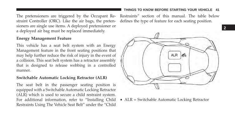
Switchable Automatic Locking Retractor (ALR)
The seat belt in the passenger seating position isequipped with a Switchable Automatic Locking Retractor(ALR) which is used to secure a child restraint system.For additional information, refer to “Installing ChildRestraints Using The Vehicle Seat Belt” under the “Child
Restraints” section of this manual. The table belowdefines the type of feature for each seating position.
• ALR = Switchable Automatic Locking Retractor
2
THINGS TO KNOW BEFORE STARTING YOUR VEHICLE 41
If the passenger seating position is equipped with anALR and is being used for normal usage, only pull theseat belt webbing out far enough to comfortably wraparound the occupant’s mid-section so as to not activatethe ALR. If the ALR is activated, you will hear a clickingsound as the seat belt retracts. Allow the webbing toretract completely in this case and then carefully pull outonly the amount of webbing necessary to comfortablywrap around the occupant’s mid-section. Slide the latchplate into the buckle until you hear a �click.�
In Automatic Locking Mode, the shoulder belt is auto-matically pre-locked. The seat belt will still retract toremove any slack in the shoulder belt. Use the AutomaticLocking Mode anytime a child restraint is installed in aseating position that has a seat belt with this feature.Children 12 years old and under should always beproperly restrained in a vehicle with a rear seat.
WARNING!
• Never place a rear-facing child restraint in front ofan air bag. A deploying Passenger Advanced FrontAir Bag can cause death or serious injury to a child12 years or younger, including a child in a rear-facing child restraint.
• Only use a rear-facing child restraint in a vehiclewith a rear seat.
How To Engage The Automatic Locking Mode
1. Buckle the combination lap and shoulder belt.
2. Grasp the shoulder portion and pull downward untilthe entire seat belt is extracted.
3. Allow the seat belt to retract. As the seat belt retracts,you will hear a clicking sound. This indicates the seatbelt is now in the Automatic Locking Mode.
42 THINGS TO KNOW BEFORE STARTING YOUR VEHICLE
How To Disengage The Automatic Locking Mode
Unbuckle the combination lap/shoulder belt and allow itto retract completely to disengage the Automatic LockingMode and activate the vehicle sensitive (emergency)locking mode.
WARNING!
• The seat belt assembly must be replaced if theswitchable Automatic Locking Retractor (ALR) fea-ture or any other seat belt function is not workingproperly when checked according to the proce-dures in the Service Manual.
• Failure to replace the seat belt assembly couldincrease the risk of injury in collisions.
• Do not use the Automatic Locking Mode to restrainoccupants who are wearing the seat belt or childrenwho are using booster seats. The locked mode is
(Continued)
WARNING! (Continued)only used to install rear-facing or forward-facingchild restraints that have a harness for restrainingthe child.
Supplemental Restraint System (SRS)
Air Bag System Components
Your vehicle may be equipped with the following air bagsystem components:
• Occupant Restraint Controller (ORC)
• Air Bag Warning Light
• Steering Wheel and Column
• Instrument Panel
• Knee Impact Bolsters
• Advanced Front Air Bags
2
THINGS TO KNOW BEFORE STARTING YOUR VEHICLE 43
• Supplemental Side Air Bags
• Supplemental Knee Air Bags
• Front and Side Impact Sensors
• Seat Belt Pretensioners
• Seat Belt Buckle Switch
• Seat Track Position Sensors
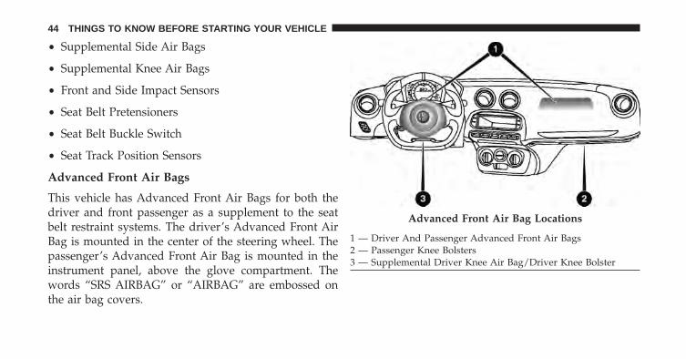
Advanced Front Air Bags
This vehicle has Advanced Front Air Bags for both thedriver and front passenger as a supplement to the seatbelt restraint systems. The driver’s Advanced Front AirBag is mounted in the center of the steering wheel. Thepassenger’s Advanced Front Air Bag is mounted in theinstrument panel, above the glove compartment. Thewords “SRS AIRBAG” or “AIRBAG” are embossed onthe air bag covers.
Advanced Front Air Bag Locations
1 — Driver And Passenger Advanced Front Air Bags2 — Passenger Knee Bolsters3 — Supplemental Driver Knee Air Bag/Driver Knee Bolster
44 THINGS TO KNOW BEFORE STARTING YOUR VEHICLE
WARNING!
• Being too close to the steering wheel or instrumentpanel during Advanced Front Air Bag deploymentcould cause serious injury, including death. Airbags need room to inflate. Sit back, comfortablyextending your arms to reach the steering wheel orinstrument panel.
• Never place a rear-facing child restraint in front ofan air bag. A deploying Passenger Advanced FrontAir Bag can cause death or serious injury to a child12 years or younger, including a child in a rear-facing child restraint.
• Only use a rear-facing child restraint in a vehiclewith a rear seat.
Advanced Front Air Bag Features
The Advanced Front Air Bag system has multistagedriver and front passenger air bags. This system providesoutput appropriate to the severity and type of collision asdetermined by the Occupant Restraint Controller (ORC),which may receive information from the front impactsensors or other system components.
The first stage inflator is triggered immediately during animpact that requires air bag deployment. A low energyoutput is used in less severe collisions. A higher energyoutput is used for more severe collisions.
This vehicle may be equipped with a driver and/or frontpassenger seat belt buckle switch that detects whetherthe driver or front passenger seat belt is buckled. The seatbelt buckle switch may adjust the inflation rate of theAdvanced Front Air Bags.
2
THINGS TO KNOW BEFORE STARTING YOUR VEHICLE 45
WARNING!
• No objects should be placed over or near the airbag on the instrument panel or steering wheelbecause any such objects could cause harm if thevehicle is in a collision severe enough to cause theair bag to inflate.
• Do not put anything on or around the air bagcovers or attempt to open them manually. You maydamage the air bags and you could be injuredbecause the air bags may no longer be functional.The protective covers for the air bag cushions aredesigned to open only when the air bags areinflating.
• Relying on the air bags alone could lead to moresevere injuries in a collision. The air bags workwith your seat belt to restrain you properly. In
(Continued)
WARNING! (Continued)some collisions, air bags won’t deploy at all. Al-ways wear your seat belts even though you have airbags.
Advanced Front Air Bag Operation
Advanced Front Air Bags are designed to provide addi-tional protection by supplementing the seat belts. Ad-vanced Front Air Bags are not expected to reduce the riskof injury in rear, side, or rollover collisions. The Ad-vanced Front Air Bags will not deploy in all frontalcollisions, including some that may produce substantialvehicle damage — for example, some pole collisions,truck underrides, and angle offset collisions.
On the other hand, depending on the type and location ofimpact, Advanced Front Air Bags may deploy in crasheswith little vehicle front-end damage but that produce asevere initial deceleration.
46 THINGS TO KNOW BEFORE STARTING YOUR VEHICLE
Because air bag sensors measure vehicle decelerationover time, vehicle speed and damage by themselves arenot good indicators of whether or not an air bag shouldhave deployed.
Seat belts are necessary for your protection in all colli-sions, and also are needed to help keep you in position,away from an inflating air bag.
When the ORC detects a collision requiring the Ad-vanced Front Air Bags, it signals the inflator units. A largequantity of non-toxic gas is generated to inflate theAdvanced Front Air Bags.
The steering wheel hub trim cover and the upper rightside of the instrument panel separate and fold out of theway as the air bags inflate to their full size. The AdvancedFront Air Bags fully inflate in less time than it takes toblink your eyes. The air bags then quickly deflate whilehelping to restrain the driver and front passenger.
Knee Impact Bolsters
The Knee Impact Bolsters help protect the knees of thedriver and front passenger, and position the front occu-pants for improved interaction with the Advanced FrontAir Bags.
WARNING!
• Do not drill, cut, or tamper with the knee impactbolsters in any way.
• Do not mount any accessories to the knee impactbolsters such as alarm lights, stereos, citizen bandradios, etc.
2
THINGS TO KNOW BEFORE STARTING YOUR VEHICLE 47
Supplemental Driver Knee Air Bag
This vehicle is equipped with a Supplemental DriverKnee Air Bag mounted in the instrument panel below thesteering column. The Supplemental Driver Knee Air Bagprovides enhanced protection during a frontal impact byworking together with the seat belts, pretensioners, andAdvanced Front Air Bags.
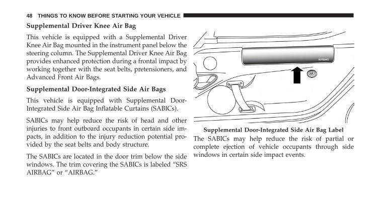
Supplemental Door-Integrated Side Air Bags
This vehicle is equipped with Supplemental Door-Integrated Side Air Bag Inflatable Curtains (SABICs).
SABICs may help reduce the risk of head and otherinjuries to front outboard occupants in certain side im-pacts, in addition to the injury reduction potential pro-vided by the seat belts and body structure.
The SABICs are located in the door trim below the sidewindows. The trim covering the SABICs is labeled “SRSAIRBAG” or “AIRBAG.”
The SABICs may help reduce the risk of partial orcomplete ejection of vehicle occupants through sidewindows in certain side impact events.
Supplemental Door-Integrated Side Air Bag Label
48 THINGS TO KNOW BEFORE STARTING YOUR VEHICLE
The SABICs deploy upward, covering the side windows.An inflating SABIC pushes the outside edge of the trimout of the way and covers the window. The SABICsinflate with enough force to injure occupants if they arenot belted and seated properly, or if items are positionedin the area where the SABICs inflate. Children are at aneven greater risk of injury from a deploying air bag.
SABICs are designed to activate in certain side impacts.The Occupant Restraint Controller (“ORC”) determineswhether the deployment of the SABIC in a particularimpact event is appropriate, based on the severity andtype of collision. The side impact sensors aid the ORC indetermining the appropriate response to impact events.The system is calibrated to deploy the SABIC on theimpact side of the vehicle during impacts that requireSABIC occupant protection. In side impacts, the SABICsdeploy independently; a left side impact deploys the leftside SABIC only and a right-side impact deploys the
right side SABIC only. Vehicle damage by itself is not agood indicator of whether or not SABICs should havedeployed.
SABICs will not deploy in all side collisions, includingsome collisions at certain angles, or some side collisionsthat do not impact the area of the passenger compart-ment. SABICs may deploy during angled or offset frontalcollisions where the Advanced Front Air Bags deploy.
SABICs are a supplement to the seat belt restraint system.SABICs deploy in less time than it takes to blink youreyes. Occupants, including children, who are up againstor very close to SABICs can be seriously injured or killed.Occupants, including children, should never lean on orsleep against the door, side windows, or area where theside air bags inflate, even if they are in an infant or childrestraint.
2
THINGS TO KNOW BEFORE STARTING YOUR VEHICLE 49
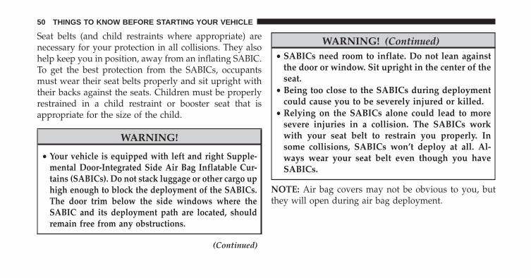
Seat belts (and child restraints where appropriate) arenecessary for your protection in all collisions. They alsohelp keep you in position, away from an inflating SABIC.To get the best protection from the SABICs, occupantsmust wear their seat belts properly and sit upright withtheir backs against the seats. Children must be properlyrestrained in a child restraint or booster seat that isappropriate for the size of the child.
WARNING!
• Your vehicle is equipped with left and right Supple-mental Door-Integrated Side Air Bag Inflatable Cur-tains (SABICs). Do not stack luggage or other cargo uphigh enough to block the deployment of the SABICs.The door trim below the side windows where theSABIC and its deployment path are located, shouldremain free from any obstructions.
(Continued)
WARNING! (Continued)• SABICs need room to inflate. Do not lean against
the door or window. Sit upright in the center of theseat.
• Being too close to the SABICs during deploymentcould cause you to be severely injured or killed.
• Relying on the SABICs alone could lead to moresevere injuries in a collision. The SABICs workwith your seat belt to restrain you properly. Insome collisions, SABICs won’t deploy at all. Al-ways wear your seat belt even though you haveSABICs.
NOTE: Air bag covers may not be obvious to you, butthey will open during air bag deployment.
50 THINGS TO KNOW BEFORE STARTING YOUR VEHICLE
If A Deployment Occurs
The Advanced Front Air Bags are designed to deflateimmediately after deployment.
NOTE: Front and/or side air bags will not deploy in allcollisions. This does not mean something is wrong withthe air bag system.
If you do have a collision which deploys the air bags, anyor all of the following may occur:
• The air bag material may sometimes cause abrasionsand/or skin reddening to the occupants as the air bagsdeploy and unfold. The abrasions are similar to fric-tion rope burns or those you might get sliding along acarpet or gymnasium floor. They are not caused bycontact with chemicals. They are not permanent andnormally heal quickly. However, if you haven’t healedsignificantly within a few days, or if you have anyblistering, see your doctor immediately.
• As the air bags deflate, you may see some smoke-likeparticles. The particles are a normal by-product of theprocess that generates the non-toxic gas used for airbag inflation. These airborne particles may irritate theskin, eyes, nose, or throat. If you have skin or eyeirritation, rinse the area with cool water. For nose orthroat irritation, move to fresh air. If the irritationcontinues, see your doctor. If these particles settle onyour clothing, follow the garment manufacturer’s in-structions for cleaning.
Do not drive your vehicle after the air bags have de-ployed. If you are involved in another collision, the airbags will not be in place to protect you.
2
THINGS TO KNOW BEFORE STARTING YOUR VEHICLE 51
WARNING!
Deployed air bags and seat belt pretensioners cannotprotect you in another collision. Have the air bags,seat belt pretensioners, and the seat belt retractorassemblies replaced by an authorized dealer imme-diately. Also, have the Occupant Restraint ControllerSystem serviced as well.
NOTE:
• Air bag covers may not be obvious in the interior trim,but they will open during air bag deployment.
• After any collision, the vehicle should be taken to anauthorized dealer immediately.
Enhanced Accident Response System
In the event of an impact, if the communication networkremains intact, and the power remains intact, dependingon the nature of the event, the ORC will determinewhether to have the Enhanced Accident Response Sys-tem perform the following functions:
• Cut off fuel to the engine.
• Flash hazard lights as long as the battery has power oruntil the hazard light button is pushed. The hazardlights can be deactivated by pushing the hazard lightbutton.
• Turn on the interior lights, which remain on as long asthe battery has power or for 15 minutes from theintervention of the Enhanced Accident Response Sys-tem.
• Unlock the power door locks.
52 THINGS TO KNOW BEFORE STARTING YOUR VEHICLE
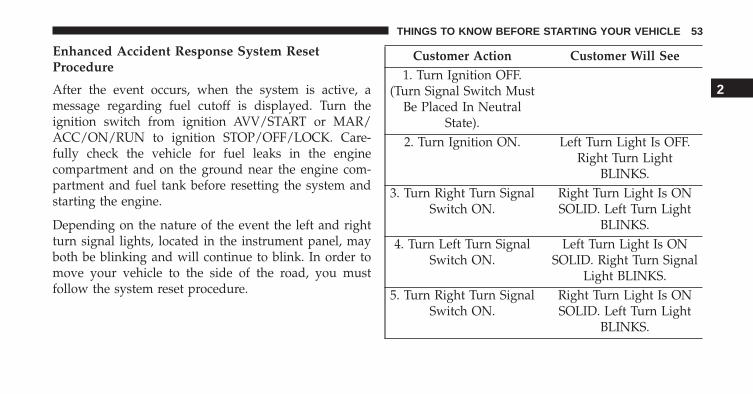
Enhanced Accident Response System ResetProcedure
After the event occurs, when the system is active, amessage regarding fuel cutoff is displayed. Turn theignition switch from ignition AVV/START or MAR/ACC/ON/RUN to ignition STOP/OFF/LOCK. Care-fully check the vehicle for fuel leaks in the enginecompartment and on the ground near the engine com-partment and fuel tank before resetting the system andstarting the engine.
Depending on the nature of the event the left and rightturn signal lights, located in the instrument panel, mayboth be blinking and will continue to blink. In order tomove your vehicle to the side of the road, you mustfollow the system reset procedure.
Customer Action Customer Will See1. Turn Ignition OFF.
(Turn Signal Switch MustBe Placed In Neutral
State).2. Turn Ignition ON. Left Turn Light Is OFF.
Right Turn LightBLINKS.
3. Turn Right Turn SignalSwitch ON.
Right Turn Light Is ONSOLID. Left Turn Light
BLINKS.4. Turn Left Turn Signal
Switch ON.Left Turn Light Is ON
SOLID. Right Turn SignalLight BLINKS.
5. Turn Right Turn SignalSwitch ON.
Right Turn Light Is ONSOLID. Left Turn Light
BLINKS.
2
THINGS TO KNOW BEFORE STARTING YOUR VEHICLE 53
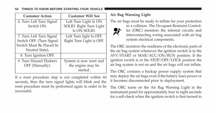
Customer Action Customer Will See6. Turn Left Turn Signal
Switch ON.Left Turn Light Is ON
SOLID. Right Turn LightIs ON SOLID.
7. Turn Left Turn SignalSwitch OFF. (Turn SignalSwitch Must Be Placed In
Neutral State).
Left Turn light Is OFF.Right Turn Light is OFF.
8. Turn Ignition OFF.9. Turn Hazard Flashers
OFF (Manually).System is now reset and
the engine may bestarted.
If a reset procedure step is not completed within 60seconds, then the turn signal lights will blink and thereset procedure must be performed again in order to besuccessful.
Air Bag Warning Light
The air bags must be ready to inflate for your protectionin a collision. The Occupant Restraint Control-ler (ORC) monitors the internal circuits andinterconnecting wiring associated with air bagsystem electrical components.
The ORC monitors the readiness of the electronic parts ofthe air bag system whenever the ignition switch is in theAVV/START or MAR/ACC/ON/RUN position. If theignition switch is in the STOP/OFF/LOCK position theair bag system is not on and the air bags will not inflate.
The ORC contains a backup power supply system thatmay deploy the air bags even if the battery loses power orit becomes disconnected prior to deployment.
The ORC turns on the Air Bag Warning Light in theinstrument panel for approximately four to eight secondsfor a self-check when the ignition switch is first turned to
54 THINGS TO KNOW BEFORE STARTING YOUR VEHICLE
the MAR/ACC/ON/RUN position. After the self-check,the Air Bag Warning Light will turn off. If the ORCdetects a malfunction in any part of the system, it turnson the Air Bag Warning Light, either momentarily orcontinuously. A single chime will sound to alert you if thelight comes on again after initial startup.
The ORC also includes diagnostics that will illuminatethe instrument panel Air Bag Warning Light if a malfunc-tion is detected that could affect the air bag system. Thediagnostics also record the nature of the malfunction.While the air bag system is designed to be maintenancefree, if any of the following occurs, have an authorizeddealer service the air bag system immediately.
• The Air Bag Warning Light does not come on duringthe four to eight seconds when the ignition switch isfirst turned to the MAR/ACC/ON/RUN position.
• The Air Bag Warning Light remains on after the four toeight-second interval.
• The Air Bag Warning Light comes on intermittently orremains on while driving.
NOTE: If the speedometer, tachometer, or any enginerelated gauges are not working, the Occupant RestraintController (ORC) may also be disabled. In this conditionthe air bags may not be ready to inflate for your protec-tion. Have an authorized dealer service the air bagsystem immediately.
WARNING!
Ignoring the Air Bag Warning Light in your instru-ment panel could mean you won’t have the air bagsto protect you in a collision. If the light does not comeon as a bulb check when the ignition is first turnedon, stays on after you start the vehicle, or if it comeson as you drive, have an authorized dealer service theair bag system immediately.
2
THINGS TO KNOW BEFORE STARTING YOUR VEHICLE 55
Maintaining Your Air Bag System
WARNING!
• Modifications to any part of the air bag systemcould cause it to fail when you need it. You couldbe injured if the air bag system is not there toprotect you. Do not modify the components orwiring, including adding any kind of badges orstickers to the steering wheel hub trim cover or theupper right side of the instrument panel. Do notmodify the front bumper, vehicle body structure, oradd aftermarket side steps or running boards.
• It is dangerous to try to repair any part of the airbag system yourself. Be sure to tell anyone whoworks on your vehicle that it has an air bag system.
• Do not attempt to modify any part of your air bagsystem. The air bag may inflate accidentally or may
(Continued)
WARNING! (Continued)not function properly if modifications are made.Take your vehicle to an authorized dealer for anyair bag system service. If your seat, including yourtrim cover and cushion, needs to be serviced in anyway (including removal or loosening/tightening ofseat attachment bolts), take the vehicle to yourauthorized dealer. Only manufacturer approvedseat accessories may be used. If it is necessary tomodify the air bag system for persons with dis-abilities, contact your authorized dealer.
Event Data Recorder (EDR)
This vehicle is equipped with an event data recorder(EDR). The main purpose of an EDR is to record, incertain crash or near crash-like situations, such as an airbag deployment or hitting a road obstacle, data that will
56 THINGS TO KNOW BEFORE STARTING YOUR VEHICLE
assist in understanding how a vehicle’s systems per-formed. The EDR is designed to record data related tovehicle dynamics and safety systems for a short period oftime, typically 30 seconds or less. The EDR in this vehicleis designed to record such data as:
• How various systems in your vehicle were operating;
• Whether or not the driver and passenger safety beltswere buckled/fastened;
• How far (if at all) the driver was depressing theaccelerator and/or brake pedal; and,
• How fast the vehicle was traveling.
These data can help provide a better understanding ofthe circumstances in which crashes and injuries occur.
NOTE: EDR data are recorded by your vehicle only if anon-trivial crash situation occurs; no data are recorded by
the EDR under normal driving conditions and no per-sonal data (e.g., name, gender, age, and crash location)are recorded. However, other parties, such as law en-forcement, could combine the EDR data with the type ofpersonally identifying data routinely acquired during acrash investigation.
To read data recorded by an EDR, special equipment isrequired, and access to the vehicle or the EDR is needed.In addition to the vehicle manufacturer, other parties,such as law enforcement, that have the special equip-ment, can read the information if they have access to thevehicle or the EDR.
Child Restraints
Everyone in your vehicle needs to be buckled up at alltimes, including babies and children. Every state in theUnited States, and every Canadian province, requiresthat small children ride in proper restraint systems. Thisis the law, and you can be prosecuted for ignoring it.
2
THINGS TO KNOW BEFORE STARTING YOUR VEHICLE 57
Children 12 years or younger should ride properlybuckled up in a rear seat, if available. According to crashstatistics, children are safer when properly restrained inthe rear seats rather than in the front.
WARNING!
In a collision, an unrestrained child can become aprojectile inside the vehicle. The force required tohold even an infant on your lap could become sogreat that you could not hold the child, no matterhow strong you are. The child and others could bebadly injured. Any child riding in your vehicleshould be in a proper restraint for the child’s size.
There are different sizes and types of restraints forchildren from newborn size to the child almost largeenough for an adult safety belt. Always check the childseat Owner’s Manual to make sure you have the correctseat for your child. Carefully read and follow all the
instructions and warnings in the child restraint Owner’sManual and on all the labels attached to the childrestraint.
Before buying any restraint system, make sure that it hasa label certifying that it meets all applicable SafetyStandards. You should also make sure that you can installit in the vehicle where you will use it.
NOTE:
• For additional information, refer towww.seatcheck.org or call 1–866–732–8243.
• Canadian residents should refer to Transport Cana-da’s website for additional information: http://www.tc.gc.ca/eng/motorvehiclesafety/safedrivers-childsafety-index-53.htm
58 THINGS TO KNOW BEFORE STARTING YOUR VEHICLE
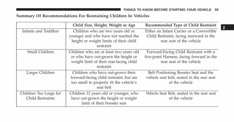
Summary Of Recommendations For Restraining Children In Vehicles
Child Size, Height, Weight or Age Recommended Type of Child RestraintInfants and Toddlers Children who are two years old or
younger and who have not reached theheight or weight limits of their child
restraint
Either an Infant Carrier or a ConvertibleChild Restraint, facing rearward in the
rear seat of the vehicle
Small Children Children who are at least two years oldor who have out-grown the height orweight limit of their rear-facing child
restraint
Forward-Facing Child Restraint with afive-point Harness, facing forward in the
rear seat of the vehicle
Larger Children Children who have out-grown theirforward-facing child restraint, but aretoo small to properly fit the vehicle’s
seat belt
Belt Positioning Booster Seat and thevehicle seat belt, seated in the rear seat
of the vehicle
Children Too Large forChild Restraints
Children 12 years old or younger, whohave out-grown the height or weight
limit of their booster seat
Vehicle Seat Belt, seated in the rear seatof the vehicle
2
THINGS TO KNOW BEFORE STARTING YOUR VEHICLE 59
Infant and Child Restraints
Safety experts recommend that children ride rear-facingin the vehicle until they are two years old or until theyreach either the height or weight limit of their rear-facingchild restraint. Two types of child restraints can be usedrear-facing: infant carriers and convertible child seats.
The infant carrier is only used rear-facing in the vehicle.It is recommended for children from birth until theyreach the weight or height limit of the infant carrier.Convertible child seats can be used either rear-facing orforward-facing in the vehicle. Convertible child seatsoften have a higher weight limit in the rear-facingdirection than infant carriers do, so they can be usedrear-facing by children who have outgrown their infantcarrier but are still less than at least two years old.Children should remain rear-facing until they reach thehighest weight or height allowed by their convertiblechild seat.
WARNING!
• Never place a rear-facing child restraint in front ofan air bag. A deploying Passenger Advanced FrontAir Bag can cause death or serious injury to a child12 years or younger, including a child in a rear-facing child restraint.
• Only use a rear-facing child restraint in a vehiclewith a rear seat.
Older Children And Child Restraints
Children who are two years old or who have outgrowntheir rear-facing convertible child seat can ride forward-facing in the vehicle. Forward-facing child seats andconvertible child seats used in the forward-facing direc-tion are for children who are over two years old or whohave outgrown the rear-facing weight or height limit oftheir rear-facing convertible child seat. Children should
60 THINGS TO KNOW BEFORE STARTING YOUR VEHICLE
remain in a forward-facing child seat with a harness foras long as possible, up to the highest weight or heightallowed by the child seat.
All children whose weight or height is above theforward-facing limit for the child seat should use abelt-positioning booster seat until the vehicle’s seat beltsfit properly. If the child cannot sit with knees bent overthe vehicle’s seat cushion while the child’s back is againstthe seatback, they should use a belt-positioning boosterseat. The child and belt-positioning booster seat are heldin the vehicle by the seat belt.
WARNING!
• Improper installation can lead to failure of aninfant or child restraint. It could come loose in acollision. The child could be badly injured orkilled. Follow the child restraint manufacturer’s
(Continued)
WARNING! (Continued)directions exactly when installing an infant orchild restraint.
• After a child restraint is installed in the vehicle, donot move the vehicle seat forward or rearwardbecause it can loosen the child restraint attach-ments. Remove the child restraint before adjustingthe vehicle seat position. When the vehicle seat hasbeen adjusted, reinstall the child restraint.
• When your child restraint is not in use, secure it inthe vehicle with the seat belt or LATCH anchor-ages, or remove it from the vehicle. Do not leave itloose in the vehicle. In a sudden stop or accident, itcould strike the occupants or seatbacks and causeserious personal injury.
2
THINGS TO KNOW BEFORE STARTING YOUR VEHICLE 61
Children Too Large For Booster Seats
Children who are large enough to wear the shoulder beltcomfortably, and whose legs are long enough to bendover the front of the seat when their back is against theseatback, should use the seat belt in a rear seat. Use thissimple 5-step test to decide whether the child can use thevehicle’s seat belt alone:
1. Can the child sit all the way back against the back ofthe vehicle seat?
2. Do the child’s knees bend comfortably over the frontof the vehicle seat – while they are still sitting all theway back?
3. Does the shoulder belt cross the child’s shoulderbetween their neck and arm?
4. Is the lap part of the belt as low as possible, touchingthe child’s thighs and not their stomach?
5. Can the child stay seated like this for the whole trip?
If the answer to any of these questions was “no,” then thechild still needs to use a booster seat in this vehicle. If thechild is using the lap/shoulder belt, check seat belt fitperiodically and make sure the seat belt buckle is latched.A child’s squirming or slouching can move the belt out ofposition. If the shoulder belt contacts the face or neck,move the child closer to the center of the vehicle, or usea booster seat to position the seat belt on the childcorrectly.
WARNING!
Never allow a child to put the shoulder belt under anarm or behind their back. In a crash, the shoulder beltwill not protect a child properly, which may result inserious injury or death. A child must always wearboth the lap and shoulder portions of the seat beltcorrectly.
62 THINGS TO KNOW BEFORE STARTING YOUR VEHICLE
Installing Child Restraints Using The Vehicle SeatBelt
The seat belts in the passenger seating positions areequipped with a Switchable Automatic Locking Retractor(ALR) that is designed to keep the lap portion of the seatbelt tight around the child restraint so that it is notnecessary to use a locking clip. The ALR retractor can be“switched” into a locked mode by pulling all of thewebbing out of the retractor and then letting the webbingretract back into the retractor. If it is locked, the ALR willmake a clicking noise while the webbing is pulled backinto the retractor. Refer to “Occupant Restraints” in“Things To Know Before Starting Your Vehicle” foradditional information on ALR.
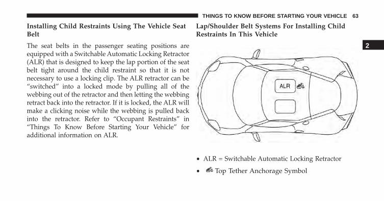
Lap/Shoulder Belt Systems For Installing ChildRestraints In This Vehicle
• ALR = Switchable Automatic Locking Retractor
• Top Tether Anchorage Symbol
2
THINGS TO KNOW BEFORE STARTING YOUR VEHICLE 63
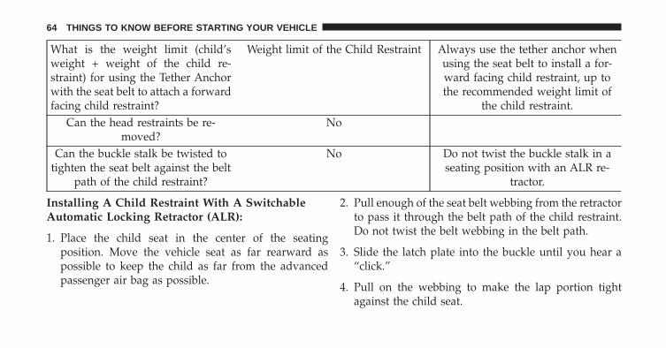
What is the weight limit (child’sweight + weight of the child re-straint) for using the Tether Anchorwith the seat belt to attach a forwardfacing child restraint?
Weight limit of the Child Restraint Always use the tether anchor whenusing the seat belt to install a for-ward facing child restraint, up tothe recommended weight limit of
the child restraint.Can the head restraints be re-
moved?No
Can the buckle stalk be twisted totighten the seat belt against the belt
path of the child restraint?
No Do not twist the buckle stalk in aseating position with an ALR re-
tractor.
Installing A Child Restraint With A SwitchableAutomatic Locking Retractor (ALR):
1. Place the child seat in the center of the seatingposition. Move the vehicle seat as far rearward aspossible to keep the child as far from the advancedpassenger air bag as possible.
2. Pull enough of the seat belt webbing from the retractorto pass it through the belt path of the child restraint.Do not twist the belt webbing in the belt path.
3. Slide the latch plate into the buckle until you hear a“click.”
4. Pull on the webbing to make the lap portion tightagainst the child seat.
64 THINGS TO KNOW BEFORE STARTING YOUR VEHICLE
5. To lock the seat belt, pull down on the shoulder part ofthe belt until you have pulled all the seat belt webbingout of the retractor. Then, allow the webbing to retractback into the retractor. As the webbing retracts, youwill hear a clicking sound. This means the seat belt isnow in the Automatic Locking mode.
6. Try to pull the webbing out of the retractor. If it islocked, you should not be able to pull out any web-bing. If the retractor is not locked, repeat step 5.
7. Finally, pull up on any excess webbing to tighten thelap portion around the child restraint while you pushthe child restraint rearward and downward into thevehicle seat.
8. If the child restraint has a top tether strap and theseating position has a top tether anchorage, connectthe tether strap to the anchorage and tighten the tether
strap. See the section “Installing Child RestraintsUsing the Top Tether Anchorage” for directions toattach a tether anchor.
9. Test that the child restraint is installed tightly bypulling back and forth on the child seat at the beltpath. It should not move more than 1 inch (25.4 mm)in any direction.
Any seat belt system will loosen with time, so check thebelt occasionally, and pull it tight if necessary.
Installing Child Restraints Using The Top TetherAnchorage:
WARNING!
Do not attach a tether strap for a rear-facing car seatto any location in front of the car seat, including theseat frame or a tether anchorage. Only attach the
(Continued)
2
THINGS TO KNOW BEFORE STARTING YOUR VEHICLE 65
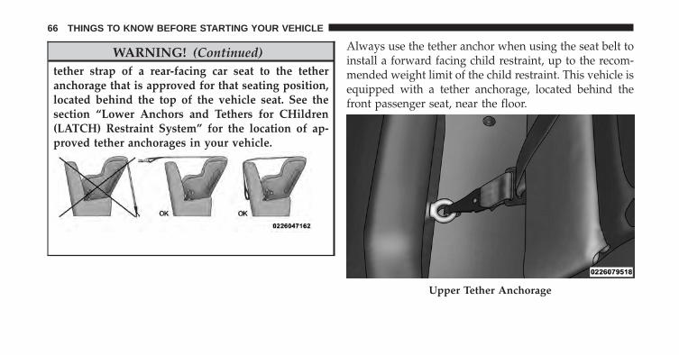
WARNING! (Continued)tether strap of a rear-facing car seat to the tetheranchorage that is approved for that seating position,located behind the top of the vehicle seat. See thesection “Lower Anchors and Tethers for CHildren(LATCH) Restraint System” for the location of ap-proved tether anchorages in your vehicle.
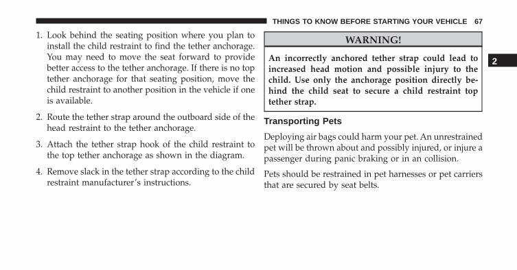
Always use the tether anchor when using the seat belt toinstall a forward facing child restraint, up to the recom-mended weight limit of the child restraint. This vehicle isequipped with a tether anchorage, located behind thefront passenger seat, near the floor.
Upper Tether Anchorage
66 THINGS TO KNOW BEFORE STARTING YOUR VEHICLE
1. Look behind the seating position where you plan toinstall the child restraint to find the tether anchorage.You may need to move the seat forward to providebetter access to the tether anchorage. If there is no toptether anchorage for that seating position, move thechild restraint to another position in the vehicle if oneis available.
2. Route the tether strap around the outboard side of thehead restraint to the tether anchorage.
3. Attach the tether strap hook of the child restraint tothe top tether anchorage as shown in the diagram.
4. Remove slack in the tether strap according to the childrestraint manufacturer’s instructions.
WARNING!
An incorrectly anchored tether strap could lead toincreased head motion and possible injury to thechild. Use only the anchorage position directly be-hind the child seat to secure a child restraint toptether strap.
Transporting Pets
Deploying air bags could harm your pet. An unrestrainedpet will be thrown about and possibly injured, or injure apassenger during panic braking or in an collision.
Pets should be restrained in pet harnesses or pet carriersthat are secured by seat belts.
2
THINGS TO KNOW BEFORE STARTING YOUR VEHICLE 67
ENGINE BREAK-IN RECOMMENDATIONS
A long break-in period is not required for the drivetrain(engine, transmission, and rear axle) in your new vehicle.
Driving your vehicle with a new transmission requires nospecial techniques but, to reach optimal shifting qualityand help with engine Break-in, Dynamic and Race Modewill be inhibited until the vehicle has accumulated 155miles (250 km).
Additionally, for the first 200 miles (300 km), followingthese few simple guidelines is all that is necessary for agood break-in.
• Avoid very aggressive driving.
• Avoid driving at a constant speed, either fast or slow,for long periods.
• Do not make any full throttle starts and avoid fullthrottle acceleration while cruising within the postedspeed limits of local traffic laws.
• Use the proper gear for your speed range.
• Wait until the engine has reached normal operatingtemperature before driving at the recommended maxi-mum break-in speed.
• Avoid excessive idling.
• Check the engine oil level at every fuel fill.
68 THINGS TO KNOW BEFORE STARTING YOUR VEHICLE
SAFETY TIPS
Transporting Passengers
NEVER TRANSPORT PASSENGERS IN THE CARGOAREA.
WARNING!
• Do not leave children or animals inside parkedvehicles in hot weather. Interior heat build-up maycause serious injury or death.
• It is extremely dangerous to ride in a cargo area,inside or outside of a vehicle. In a collision, peopleriding in these areas are more likely to be seriouslyinjured or killed.
• Do not allow people to ride in any area of your vehiclethat is not equipped with seats and seat belts.
• Be sure everyone in your vehicle is in a seat andusing a seat belt properly.
Exhaust Gas
WARNING!
Exhaust gases can injure or kill. They contain carbonmonoxide (CO), which is colorless and odorless.Breathing it can make you unconscious and caneventually poison you. To avoid breathing (CO),follow these safety tips:• Do not run the engine in a closed garage or in
confined areas any longer than needed to moveyour vehicle in or out of the area.
• If you are required to drive with the trunk/liftgate/rear doors open, make sure that all windows areclosed and the climate control BLOWER switch isset at high speed. DO NOT use the recirculationmode.
(Continued)
2
THINGS TO KNOW BEFORE STARTING YOUR VEHICLE 69
WARNING! (Continued)• If it is necessary to sit in a parked vehicle with the
engine running, adjust your heating or coolingcontrols to force outside air into the vehicle. Set theblower at high speed.
The best protection against carbon monoxide entry intothe vehicle body is a properly maintained engine exhaustsystem.
Whenever a change is noticed in the sound of the exhaustsystem, when exhaust fumes can be detected inside thevehicle, or when the underside or rear of the vehicle isdamaged, have a competent mechanic inspect the com-plete exhaust system and adjacent body areas for broken,damaged, deteriorated, or mispositioned parts. Openseams or loose connections could permit exhaust fumesto seep into the passenger compartment. In addition,inspect the exhaust system each time the vehicle is raisedfor lubrication or oil change. Replace as required.
Safety Checks You Should Make Inside The Vehicle
Seat Belts
Inspect the belt system periodically, checking for cuts,frays, and loose parts. Damaged parts must be replacedimmediately. Do not disassemble or modify the system.
Front seat belt assemblies must be replaced after acollision. Seat belt assemblies must be replaced after acollision if they have been damaged (i.e., bent retractor,torn webbing, etc.). If there is any question regarding beltor retractor condition, replace the belt.
Air Bag Warning Light
The light should come on and remain on for four to eightseconds as a bulb check when the ignition is first cycledto ON. If the light is not lit during starting, see yourauthorized dealer. If the light stays on, flickers, or comeson while driving, have the system checked by an autho-rized dealer.
70 THINGS TO KNOW BEFORE STARTING YOUR VEHICLE
Defroster
Check operation by selecting the defrost mode and placethe blower control on high speed. You should be able tofeel the air directed against the windshield. See yourauthorized dealer for service if your defroster is inoper-able.
Floor Mat Safety Information
Always use floor mats designed to fit the foot well ofyour vehicle. Use only floor mats that leave the pedalarea unobstructed and that are firmly secured so thatthey cannot slip out of position and interfere with thepedals or impair safe operation of your vehicle in otherways.
Periodic Safety Checks You Should Make OutsideThe Vehicle
Tires
Examine tires for excessive tread wear and uneven wearpatterns. Check for stones, nails, glass, or other objectslodged in the tread. Inspect the tread and sidewall forcuts and cracks. Check the wheel nuts for tightness.Check the tires for proper pressure.
Lights
Have someone observe the operation of brake lights andexterior lights while you work the controls. Check turnsignal and high beam indicator lights on the instrumentpanel.
2
THINGS TO KNOW BEFORE STARTING YOUR VEHICLE 71
Door Latches
Check for positive closing, latching, and locking.
Fluid Leaks
Check area under vehicle after overnight parking for fuel,engine coolant, oil, or other fluid leaks. Also, if gasolinefumes are detected or if fuel, power steering fluid (ifequipped), or brake fluid leaks are suspected, the causeshould be located and corrected immediately.
72 THINGS TO KNOW BEFORE STARTING YOUR VEHICLE
UNDERSTANDING THE FEATURES OF YOUR VEHICLE
CONTENTS� MIRRORS . . . . . . . . . . . . . . . . . . . . . . . . . . . . .76
▫ Inside Day/Night Mirror . . . . . . . . . . . . . . . .76
▫ Outside Mirrors . . . . . . . . . . . . . . . . . . . . . . .77
▫ Power Mirrors . . . . . . . . . . . . . . . . . . . . . . . .77
▫ Folding Mirrors. . . . . . . . . . . . . . . . . . . . . . . .78
▫ Heated Mirrors . . . . . . . . . . . . . . . . . . . . . . .78
� REMOVABLE SOFT TOP — IF EQUIPPED . . . . . .79
▫ Installing The Soft Top. . . . . . . . . . . . . . . . . . .80
� SEATS . . . . . . . . . . . . . . . . . . . . . . . . . . . . . . .86
▫ Manual Seats . . . . . . . . . . . . . . . . . . . . . . . . .87
▫ Non-Adjustable Head Restraints . . . . . . . . . . .89
� TO OPEN AND CLOSE THE DECKLID . . . . . . .90
� LIGHTS . . . . . . . . . . . . . . . . . . . . . . . . . . . . . .93
▫ Multifunction Lever. . . . . . . . . . . . . . . . . . . . .93
▫ Headlights . . . . . . . . . . . . . . . . . . . . . . . . . . .94
▫ Daytime Running Lights . . . . . . . . . . . . . . . . .94
▫ High Beams . . . . . . . . . . . . . . . . . . . . . . . . . .94
▫ Flash-To-Pass . . . . . . . . . . . . . . . . . . . . . . . . .95
▫ Parking Lights . . . . . . . . . . . . . . . . . . . . . . . .95
▫ Turn Signals . . . . . . . . . . . . . . . . . . . . . . . . . .95
3
▫ Lane Change Assist . . . . . . . . . . . . . . . . . . . .95
▫ Follow Me Home/Headlight Delay —If Equipped . . . . . . . . . . . . . . . . . . . . . . . . . .95
▫ Dimmer Controls . . . . . . . . . . . . . . . . . . . . . .96
▫ Interior Light . . . . . . . . . . . . . . . . . . . . . . . . .97
� WINDSHIELD WIPERS AND WASHERS . . . . . .98
▫ Intermittent Wiper System . . . . . . . . . . . . . . .98
▫ Windshield Wiper Operation . . . . . . . . . . . . . .99
▫ Mist . . . . . . . . . . . . . . . . . . . . . . . . . . . . . . . .99
▫ Windshield Washers . . . . . . . . . . . . . . . . . . . .99
� TILT/TELESCOPING STEERING COLUMN . . .100
� ELECTRONIC SPEED CONTROL —IF EQUIPPED . . . . . . . . . . . . . . . . . . . . . . . . .101
▫ To Activate . . . . . . . . . . . . . . . . . . . . . . . . . .101
▫ To Set A Desired Speed . . . . . . . . . . . . . . . . .102
▫ To Deactivate . . . . . . . . . . . . . . . . . . . . . . . .102
▫ To Resume Speed . . . . . . . . . . . . . . . . . . . . .102
▫ To Vary The Speed Setting . . . . . . . . . . . . . . .103
▫ To Accelerate For Passing . . . . . . . . . . . . . . .104
� PARKING SENSORS — IF EQUIPPED . . . . . . .104
▫ Activation/Deactivation . . . . . . . . . . . . . . . . .105
▫ Acoustic Signal . . . . . . . . . . . . . . . . . . . . . . .105
▫ Indications On Display — If Equipped . . . . . .106
▫ Fault Indication . . . . . . . . . . . . . . . . . . . . . . .107
▫ General Warnings . . . . . . . . . . . . . . . . . . . . .107
� POWER OUTLETS . . . . . . . . . . . . . . . . . . . . .109
74 UNDERSTANDING THE FEATURES OF YOUR VEHICLE
� CIGAR LIGHTER AND ASH RECEIVER —IF EQUIPPED. . . . . . . . . . . . . . . . . . . . . . . . . .111
� CUPHOLDER . . . . . . . . . . . . . . . . . . . . . . . . .112
� STORAGE . . . . . . . . . . . . . . . . . . . . . . . . . . . .112
▫ Seatback Storage . . . . . . . . . . . . . . . . . . . . . .112
▫ Console Features . . . . . . . . . . . . . . . . . . . . . .113
▫ Rear Compartment Storage . . . . . . . . . . . . . . .1133
UNDERSTANDING THE FEATURES OF YOUR VEHICLE 75
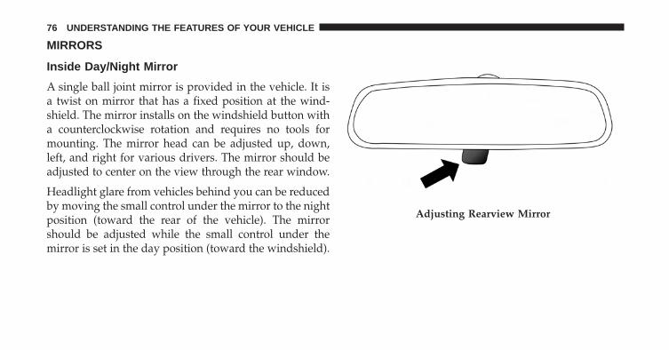
MIRRORS
Inside Day/Night Mirror
A single ball joint mirror is provided in the vehicle. It isa twist on mirror that has a fixed position at the wind-shield. The mirror installs on the windshield button witha counterclockwise rotation and requires no tools formounting. The mirror head can be adjusted up, down,left, and right for various drivers. The mirror should beadjusted to center on the view through the rear window.
Headlight glare from vehicles behind you can be reducedby moving the small control under the mirror to the nightposition (toward the rear of the vehicle). The mirrorshould be adjusted while the small control under themirror is set in the day position (toward the windshield).
Adjusting Rearview Mirror
76 UNDERSTANDING THE FEATURES OF YOUR VEHICLE
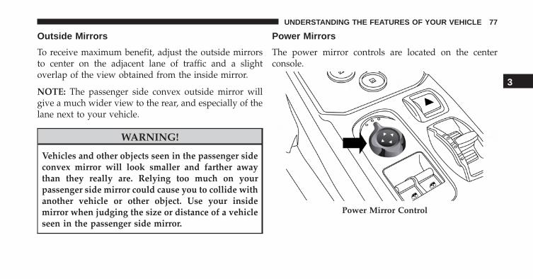
Outside Mirrors
To receive maximum benefit, adjust the outside mirrorsto center on the adjacent lane of traffic and a slightoverlap of the view obtained from the inside mirror.
NOTE: The passenger side convex outside mirror willgive a much wider view to the rear, and especially of thelane next to your vehicle.
WARNING!
Vehicles and other objects seen in the passenger sideconvex mirror will look smaller and farther awaythan they really are. Relying too much on yourpassenger side mirror could cause you to collide withanother vehicle or other object. Use your insidemirror when judging the size or distance of a vehicleseen in the passenger side mirror.
Power Mirrors
The power mirror controls are located on the centerconsole.
Power Mirror Control
3
UNDERSTANDING THE FEATURES OF YOUR VEHICLE 77
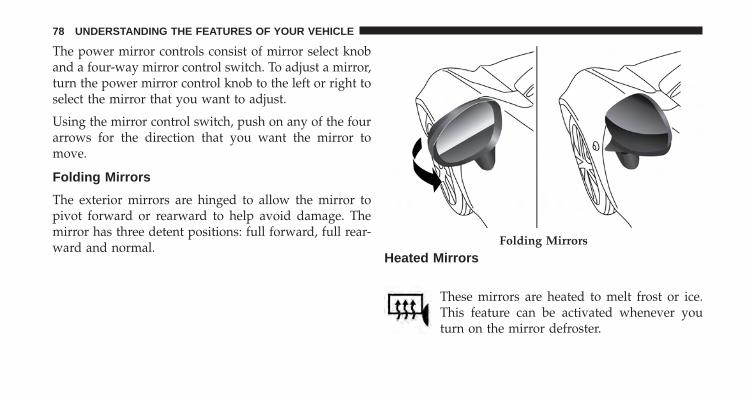
The power mirror controls consist of mirror select knoband a four-way mirror control switch. To adjust a mirror,turn the power mirror control knob to the left or right toselect the mirror that you want to adjust.
Using the mirror control switch, push on any of the fourarrows for the direction that you want the mirror tomove.
Folding Mirrors
The exterior mirrors are hinged to allow the mirror topivot forward or rearward to help avoid damage. Themirror has three detent positions: full forward, full rear-ward and normal.
Heated Mirrors
These mirrors are heated to melt frost or ice.This feature can be activated whenever youturn on the mirror defroster.
Folding Mirrors
78 UNDERSTANDING THE FEATURES OF YOUR VEHICLE
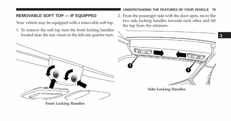
REMOVABLE SOFT TOP — IF EQUIPPED
Your vehicle may be equipped with a removable soft top.
1. To remove the soft top turn the front locking handleslocated near the sun visors to the left one quarter turn.
2. From the passenger side with the door open, move thetwo side locking handles towards each other and liftthe top from the retainers.
Front Locking Handles
Side Locking Handles
3
UNDERSTANDING THE FEATURES OF YOUR VEHICLE 79
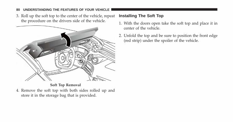
3. Roll up the soft top to the center of the vehicle, repeatthe procedure on the drivers side of the vehicle.
4. Remove the soft top with both sides rolled up andstore it in the storage bag that is provided.
Installing The Soft Top
1. With the doors open take the soft top and place it incenter of the vehicle.
2. Unfold the top and be sure to position the front edge(red strip) under the spoiler of the vehicle.
Soft Top Removal
80 UNDERSTANDING THE FEATURES OF YOUR VEHICLE
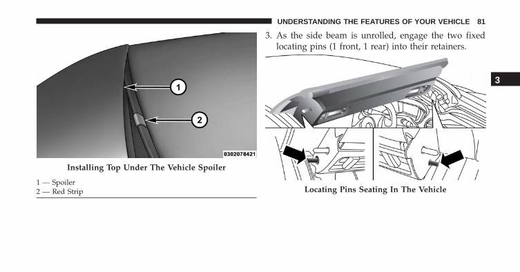
3. As the side beam is unrolled, engage the two fixedlocating pins (1 front, 1 rear) into their retainers.
Installing Top Under The Vehicle Spoiler
1 — Spoiler2 — Red Strip Locating Pins Seating In The Vehicle
3
UNDERSTANDING THE FEATURES OF YOUR VEHICLE 81
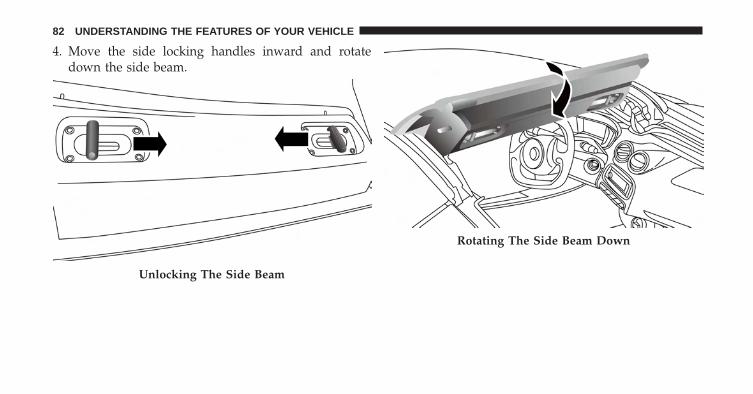
4. Move the side locking handles inward and rotatedown the side beam.
Unlocking The Side Beam
Rotating The Side Beam Down
82 UNDERSTANDING THE FEATURES OF YOUR VEHICLE
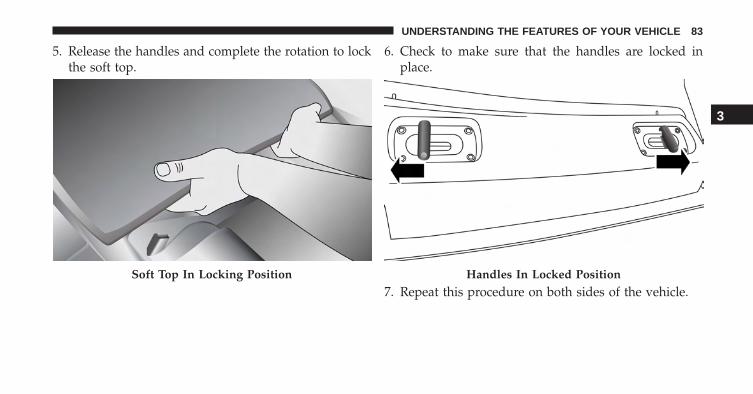
5. Release the handles and complete the rotation to lockthe soft top.
6. Check to make sure that the handles are locked inplace.
7. Repeat this procedure on both sides of the vehicle.Soft Top In Locking Position Handles In Locked Position
3
UNDERSTANDING THE FEATURES OF YOUR VEHICLE 83
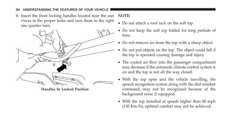
8. Insert the front locking handles located near the sunvisors in the proper holes and turn them to the rightone quarter turn.
NOTE:
• Do not attach a roof rack on the soft top.
• Do not keep the soft top folded for long periods oftime.
• Do not remove ice from the top with a sharp object.
• Do not put objects on the top. The object could fall ifthe top is operated causing damage and injury.
• The cooled air flow into the passenger compartmentmay decrease if the automatic climate control system ison and the top is not all the way closed.
• With the top open and the vehicle travelling, thespeech recognition system along with the dial numbercommand, may not be recognized because of thebackground noise if equipped.
• With the top installed at speeds higher than 80 mph(130 Km/h), optimal comfort may not be achieved.
Handles In Locked Position
84 UNDERSTANDING THE FEATURES OF YOUR VEHICLE
The top fabric is treated with a special water repellent,waterproof product. The water-repellent properties willdegrade in time with exposure to the weather elements.Observe the following instructions for washing:
NOTE:
• Use of specific products is recommended for washingthe top.
• Bird droppings must be washed off immediately andthoroughly as the acid they contain is particularlyaggressive.
• Never use high-pressure washing systems.
• Hand washing is recommended; modern automaticwashing systems equipped with soft brushes which donot apply excessive pressure and employ specific softtop products may be used.
• When using steam washers or high-pressure powerwashers, maintain a suitable distance and do notexceed a maximum temperature of 140 °F (60 °C).Damage, alterations and water infiltrations may occurif the distance is too small.
• If a water jet is used, direct away from the edges of thefabric to prevent water infiltrations.
• Never use alcohol, petroleum products, chemicalproducts, detergents, stain removers, wax, solvents,and “wash and polish” products.
• Remove as much dirt from the surface of the top witha soft brush or vacuum cleaner before washing it. Thisoperation will considerably improve the final result. Inlack of specific products, use water and mild soapapplied with a sponge preferably in the shade forwashing. Rinse the top with clean water after havingeliminated all the stains.
3
UNDERSTANDING THE FEATURES OF YOUR VEHICLE 85
• Rinse immediately to remove soap to prevent stains.
• Leave the vehicle in the shade after washing avoidingdirect sunlight.
• Use specific waterproofing products for fabric topsand follow the instructions on the product containerfor best results.
• The rubber seals of the top must be washed with wateronly. Apply talcum power or use specific rubber careproducts (silicone spray) if the seals are dry or partiallystuck.
SEATS
Seats are a part of the Occupant Restraint System of thevehicle.
WARNING!
• It is dangerous to ride in a cargo area, inside oroutside of a vehicle. In a collision, people riding inthese areas are more likely to be seriously injuredor killed.
• Do not allow people to ride in any area of yourvehicle that is not equipped with seats and seatbelts. In a collision, people riding in these areas aremore likely to be seriously injured or killed.
• Be sure everyone in your vehicle is in a seat andusing a seat belt properly.
86 UNDERSTANDING THE FEATURES OF YOUR VEHICLE
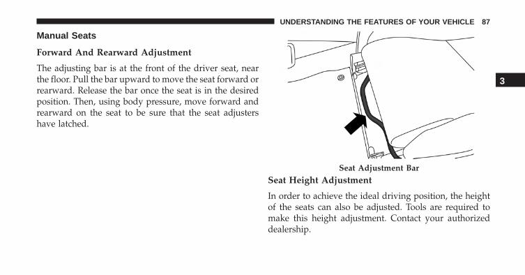
Manual Seats
Forward And Rearward Adjustment
The adjusting bar is at the front of the driver seat, nearthe floor. Pull the bar upward to move the seat forward orrearward. Release the bar once the seat is in the desiredposition. Then, using body pressure, move forward andrearward on the seat to be sure that the seat adjustershave latched.
Seat Height Adjustment
In order to achieve the ideal driving position, the heightof the seats can also be adjusted. Tools are required tomake this height adjustment. Contact your authorizeddealership.
Seat Adjustment Bar
3
UNDERSTANDING THE FEATURES OF YOUR VEHICLE 87
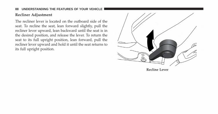
Recliner Adjustment
The recliner lever is located on the outboard side of theseat. To recline the seat, lean forward slightly, pull therecliner lever upward, lean backward until the seat is inthe desired position, and release the lever. To return theseat to its full upright position, lean forward, pull therecliner lever upward and hold it until the seat returns toits full upright position.
Recline Lever
88 UNDERSTANDING THE FEATURES OF YOUR VEHICLE
WARNING!
• Adjusting a seat while driving may be dangerous.Moving a seat while driving could result in loss ofcontrol which could cause a collision and seriousinjury or death.
• Seats should be adjusted before fastening the seatbelts and while the vehicle is parked. Seriousinjury or death could result from a poorly adjustedseat belt.
• Do not ride with the seatback reclined so that theshoulder belt is no longer resting against your chest.In a collision you could slide under the seat belt,which could result in serious injury or death.
Non-Adjustable Head Restraints
The non-adjustable head restraints are form fitted intothe upper structure of the seatback and are designed toreduce the risk of injury by restricting head movement inthe event of a rear impact. The seatback should beproperly adjusted to an upright position where the headrestraint is positioned as close as possible to the back ofyour head.
WARNING!
Be certain that the seatback is locked securely intoposition. Otherwise, the seat will not provide theproper stability for passengers. An improperlylatched seatback could cause serious injury.
(Continued)
3
UNDERSTANDING THE FEATURES OF YOUR VEHICLE 89
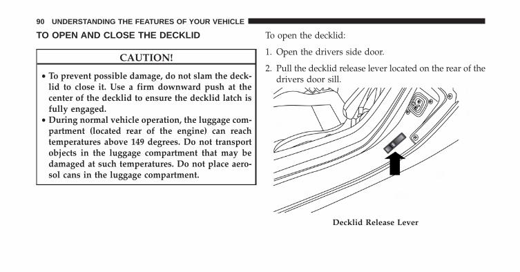
TO OPEN AND CLOSE THE DECKLID
CAUTION!
• To prevent possible damage, do not slam the deck-lid to close it. Use a firm downward push at thecenter of the decklid to ensure the decklid latch isfully engaged.
• During normal vehicle operation, the luggage com-partment (located rear of the engine) can reachtemperatures above 149 degrees. Do not transportobjects in the luggage compartment that may bedamaged at such temperatures. Do not place aero-sol cans in the luggage compartment.
To open the decklid:
1. Open the drivers side door.
2. Pull the decklid release lever located on the rear of thedrivers door sill.
Decklid Release Lever
90 UNDERSTANDING THE FEATURES OF YOUR VEHICLE
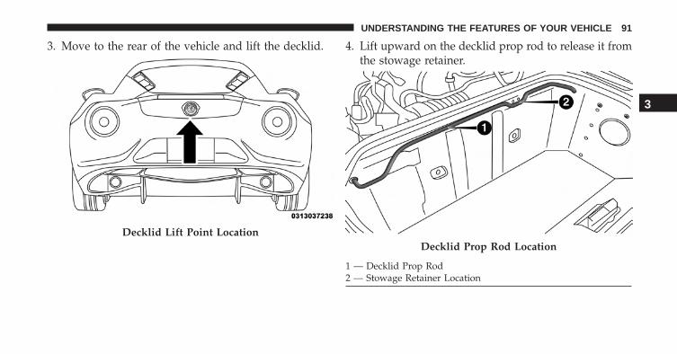
3. Move to the rear of the vehicle and lift the decklid. 4. Lift upward on the decklid prop rod to release it fromthe stowage retainer.
Decklid Lift Point LocationDecklid Prop Rod Location
1 — Decklid Prop Rod2 — Stowage Retainer Location
3
UNDERSTANDING THE FEATURES OF YOUR VEHICLE 91
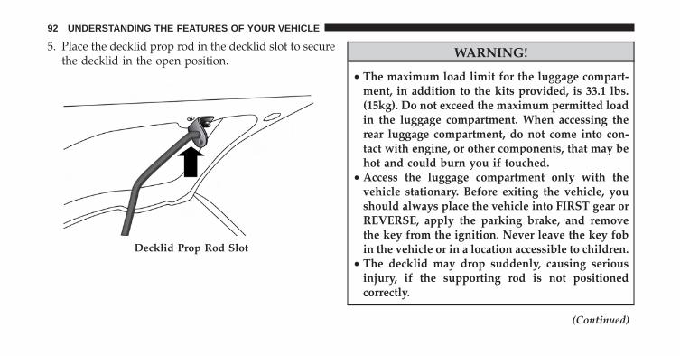
5. Place the decklid prop rod in the decklid slot to securethe decklid in the open position.
WARNING!
• The maximum load limit for the luggage compart-ment, in addition to the kits provided, is 33.1 lbs.(15kg). Do not exceed the maximum permitted loadin the luggage compartment. When accessing therear luggage compartment, do not come into con-tact with engine, or other components, that may behot and could burn you if touched.
• Access the luggage compartment only with thevehicle stationary. Before exiting the vehicle, youshould always place the vehicle into FIRST gear orREVERSE, apply the parking brake, and removethe key from the ignition. Never leave the key fobin the vehicle or in a location accessible to children.
• The decklid may drop suddenly, causing seriousinjury, if the supporting rod is not positionedcorrectly.
(Continued)
Decklid Prop Rod Slot
92 UNDERSTANDING THE FEATURES OF YOUR VEHICLE
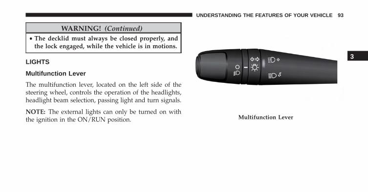
WARNING! (Continued)• The decklid must always be closed properly, and
the lock engaged, while the vehicle is in motions.
LIGHTS
Multifunction Lever
The multifunction lever, located on the left side of thesteering wheel, controls the operation of the headlights,headlight beam selection, passing light and turn signals.
NOTE: The external lights can only be turned on withthe ignition in the ON/RUN position. Multifunction Lever
3
UNDERSTANDING THE FEATURES OF YOUR VEHICLE 93
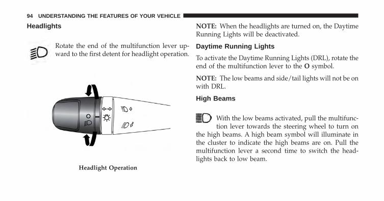
Headlights
Rotate the end of the multifunction lever up-ward to the first detent for headlight operation.
NOTE: When the headlights are turned on, the DaytimeRunning Lights will be deactivated.
Daytime Running Lights
To activate the Daytime Running Lights (DRL), rotate theend of the multifunction lever to the O symbol.
NOTE: The low beams and side/tail lights will not be onwith DRL.
High Beams
With the low beams activated, pull the multifunc-tion lever towards the steering wheel to turn on
the high beams. A high beam symbol will illuminate inthe cluster to indicate the high beams are on. Pull themultifunction lever a second time to switch the head-lights back to low beam.
Headlight Operation
94 UNDERSTANDING THE FEATURES OF YOUR VEHICLE
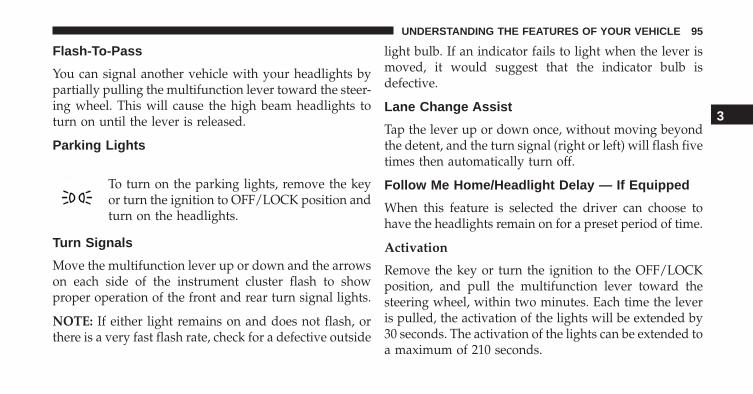
Flash-To-Pass
You can signal another vehicle with your headlights bypartially pulling the multifunction lever toward the steer-ing wheel. This will cause the high beam headlights toturn on until the lever is released.
Parking Lights
To turn on the parking lights, remove the keyor turn the ignition to OFF/LOCK position andturn on the headlights.
Turn Signals
Move the multifunction lever up or down and the arrowson each side of the instrument cluster flash to showproper operation of the front and rear turn signal lights.
NOTE: If either light remains on and does not flash, orthere is a very fast flash rate, check for a defective outside
light bulb. If an indicator fails to light when the lever ismoved, it would suggest that the indicator bulb isdefective.
Lane Change Assist
Tap the lever up or down once, without moving beyondthe detent, and the turn signal (right or left) will flash fivetimes then automatically turn off.
Follow Me Home/Headlight Delay — If Equipped
When this feature is selected the driver can choose tohave the headlights remain on for a preset period of time.
Activation
Remove the key or turn the ignition to the OFF/LOCKposition, and pull the multifunction lever toward thesteering wheel, within two minutes. Each time the leveris pulled, the activation of the lights will be extended by30 seconds. The activation of the lights can be extended toa maximum of 210 seconds.
3
UNDERSTANDING THE FEATURES OF YOUR VEHICLE 95
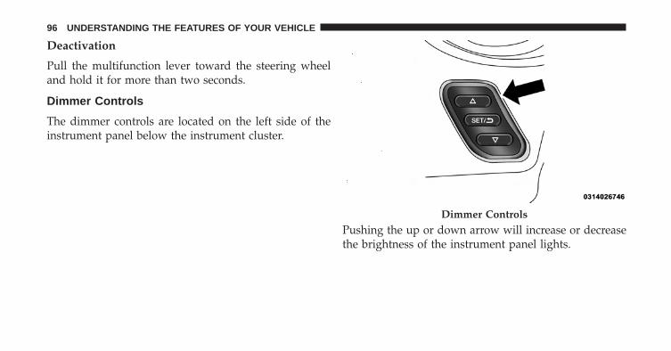
Deactivation
Pull the multifunction lever toward the steering wheeland hold it for more than two seconds.
Dimmer Controls
The dimmer controls are located on the left side of theinstrument panel below the instrument cluster.
Pushing the up or down arrow will increase or decreasethe brightness of the instrument panel lights.
Dimmer Controls
96 UNDERSTANDING THE FEATURES OF YOUR VEHICLE
Interior Light
The interior light is located in the headliner in betweenthe sun visors. The interior light can be set to threedifferent positions (Off/Left Position, Center Position,On/Right Position).
Using the interior light lens, push the lens to the rightfrom its center position and the lights are always on.Push the lens to the left from its center position and thelights are always off. Leave the lens in the center position,and the light is turned on and off when the doors areopened or closed.
CAUTION!
Before getting out of the vehicle be sure that theOverhead Dome Lamp is in the center position orthat the lights are off to avoid draining the battery.
Interior Light Timing (Center Position)
There are four different modes of operation that can beactivated in this position:
• When one door is opened a three minute timer isactivated.
Interior Light (Off Position Shown)
3
UNDERSTANDING THE FEATURES OF YOUR VEHICLE 97
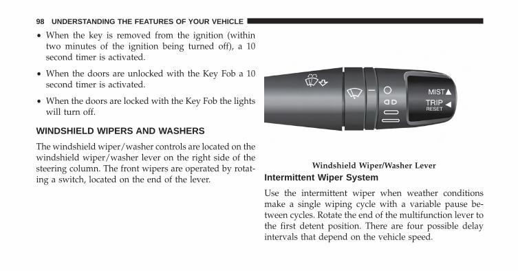
• When the key is removed from the ignition (withintwo minutes of the ignition being turned off), a 10second timer is activated.
• When the doors are unlocked with the Key Fob a 10second timer is activated.
• When the doors are locked with the Key Fob the lightswill turn off.
WINDSHIELD WIPERS AND WASHERS
The windshield wiper/washer controls are located on thewindshield wiper/washer lever on the right side of thesteering column. The front wipers are operated by rotat-ing a switch, located on the end of the lever. Intermittent Wiper System
Use the intermittent wiper when weather conditionsmake a single wiping cycle with a variable pause be-tween cycles. Rotate the end of the multifunction lever tothe first detent position. There are four possible delayintervals that depend on the vehicle speed.
Windshield Wiper/Washer Lever
98 UNDERSTANDING THE FEATURES OF YOUR VEHICLE
Windshield Wiper Operation
Rotate the end of the lever upward, to the first detent pastthe intermittent settings for low-speed wiper operation.Rotate the end of the lever upward to the second detentpast the intermittent settings for high-speed wiper opera-tion.
Mist
Use the mist feature when weather conditions makeoccasional usage of the wipers necessary. Push the leverupward to the mist position and release for a singlewiping cycle.
NOTE: The mist feature does not activate the washerpump; therefore, no washer fluid will be sprayed on thewindshield. The wash function must be used in order tospray the windshield with washer fluid.
Windshield Washers
To use the washer, pull the lever toward you and holdwhile spray is desired. If the lever is pulled while in thedelay range, the wiper will start and continue to operatefor three wipe cycles after the lever is released, and thenresume the intermittent interval previously selected.
If the lever is pulled while in the off position, the wiperswill operate for three wipe cycles and then turn off.
WARNING!
Sudden loss of visibility through the windshieldcould lead to a collision. You might not see othervehicles or other obstacles. To avoid sudden icing ofthe windshield during freezing weather, warm thewindshield with defroster before and during wind-shield washer use.
3
UNDERSTANDING THE FEATURES OF YOUR VEHICLE 99
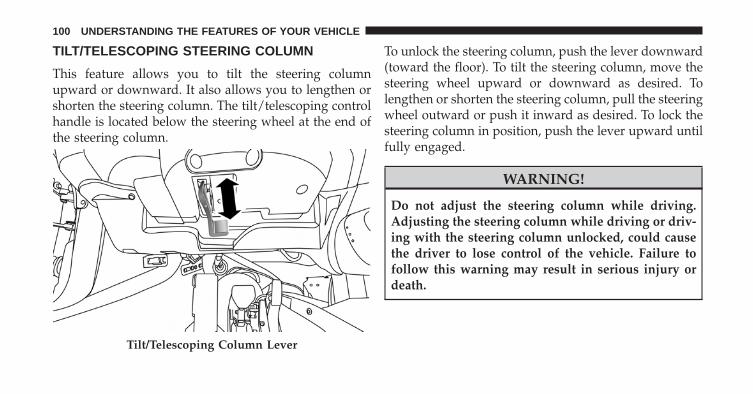
TILT/TELESCOPING STEERING COLUMN
This feature allows you to tilt the steering columnupward or downward. It also allows you to lengthen orshorten the steering column. The tilt/telescoping controlhandle is located below the steering wheel at the end ofthe steering column.
To unlock the steering column, push the lever downward(toward the floor). To tilt the steering column, move thesteering wheel upward or downward as desired. Tolengthen or shorten the steering column, pull the steeringwheel outward or push it inward as desired. To lock thesteering column in position, push the lever upward untilfully engaged.
WARNING!
Do not adjust the steering column while driving.Adjusting the steering column while driving or driv-ing with the steering column unlocked, could causethe driver to lose control of the vehicle. Failure tofollow this warning may result in serious injury ordeath.
Tilt/Telescoping Column Lever
100 UNDERSTANDING THE FEATURES OF YOUR VEHICLE
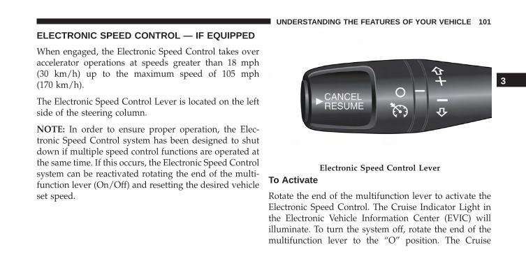
ELECTRONIC SPEED CONTROL — IF EQUIPPED
When engaged, the Electronic Speed Control takes overaccelerator operations at speeds greater than 18 mph(30 km/h) up to the maximum speed of 105 mph(170 km/h).
The Electronic Speed Control Lever is located on the leftside of the steering column.
NOTE: In order to ensure proper operation, the Elec-tronic Speed Control system has been designed to shutdown if multiple speed control functions are operated atthe same time. If this occurs, the Electronic Speed Controlsystem can be reactivated rotating the end of the multi-function lever (On/Off) and resetting the desired vehicleset speed.
To Activate
Rotate the end of the multifunction lever to activate theElectronic Speed Control. The Cruise Indicator Light inthe Electronic Vehicle Information Center (EVIC) willilluminate. To turn the system off, rotate the end of themultifunction lever to the “O” position. The Cruise
Electronic Speed Control Lever
3
UNDERSTANDING THE FEATURES OF YOUR VEHICLE 101
Indicator Light will turn off. The system should beturned off when not in use.
WARNING!
Leaving the Electronic Speed Control system onwhen not in use is dangerous. You could accidentallyset the system or cause it to go faster than you want.You could lose control and have an accident. Alwaysleave the system OFF when you are not using it.
To Set A Desired Speed
Turn the Electronic Speed Control ON. When the vehiclehas reached the desired speed, move the electronic speedcontrol lever upward SET(+) and release. Release theaccelerator and the vehicle will operate at the selectedspeed.
NOTE: The vehicle should be traveling at a steady speedand on level ground before moving the electronic speedcontrol lever upward SET(+).
To Deactivate
A soft tap on the brake pedal, pushing the RESUME/CANCEL button, or normal brake pressure while slow-ing the vehicle will deactivate Electronic Speed Controlwithout erasing the set speed memory. Rotating the endof the multifunction lever to the “O” position or turningthe ignition switch OFF erases the set speed memory.
To Resume Speed
To resume a previously set speed, push the RESUMEbutton and release. Resume can be used at any speedabove 18 mph (30 km/h).
102 UNDERSTANDING THE FEATURES OF YOUR VEHICLE
To Vary The Speed Setting
To Increase Speed
When the Electronic Speed Control is set, you can in-crease speed by tapping the Speed Control lever up (+).
The speed increment shown is dependant on the speed ofU.S. (mph) or Metric (km/h) units:
U.S. Speed (mph)
• Tapping the Speed Control lever up (+) once will resultin a 1 mph increase in set speed. Each subsequent tapof the lever results in an increase of 1 mph.
• If the lever is continually help up, the set speed willcontinue to increase until the lever is released, then thenew set speed will be established.
Metric Speed (km/h)
• Tapping the Speed Control lever up (+) once will resultin a 2 km/h increase in set speed. Each subsequent tapof the lever results in an increase of 2 km/h.
• If the lever is continually help up, the set speed willcontinue to increase until the lever is released, then thenew set speed will be established.
To Decrease Speed
When the Electronic Speed Control is set, you can decreasespeed by tapping the Speed Control lever down (-).
The speed decrement shown is dependant on the speedof U.S. (mph) or Metric (km/h) units:
U.S. Speed (mph)
• Tapping the Speed Control lever down (-) once willresult in a 1 mph decrease in set speed. Each subse-quent tap of the lever results in a decrease of 1 mph.
3
UNDERSTANDING THE FEATURES OF YOUR VEHICLE 103
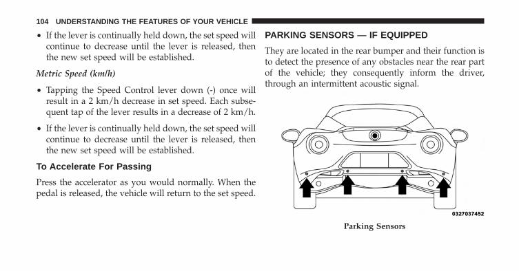
• If the lever is continually held down, the set speed willcontinue to decrease until the lever is released, thenthe new set speed will be established.
Metric Speed (km/h)
• Tapping the Speed Control lever down (-) once willresult in a 2 km/h decrease in set speed. Each subse-quent tap of the lever results in a decrease of 2 km/h.
• If the lever is continually held down, the set speed willcontinue to decrease until the lever is released, thenthe new set speed will be established.
To Accelerate For Passing
Press the accelerator as you would normally. When thepedal is released, the vehicle will return to the set speed.
PARKING SENSORS — IF EQUIPPED
They are located in the rear bumper and their function isto detect the presence of any obstacles near the rear partof the vehicle; they consequently inform the driver,through an intermittent acoustic signal.
Parking Sensors
104 UNDERSTANDING THE FEATURES OF YOUR VEHICLE
Activation/Deactivation
The sensors are automatically activated when reversegear is engaged. As the obstacle behind the vehicle getscloser, the acoustic signal becomes more frequent.
Acoustic Signal
When reverse gear is engaged and there is an obstaclebehind the vehicle, an acoustic signal is emitted whichvaries according to the distance of the bumper from theobstacle.
The frequency of the acoustic signal:
• Increases as the distance between vehicle and obstacledecreases, culminating in a continuous acoustic signalwhen the distance is less than approximately 12 in(30 cm).
• Decreases if the distance from the obstacle increases,until the signal ceases entirely.
• Remains constant if the distance between vehicle andobstacle remains unchanged; if this situation concernsthe side sensors, the signal will stop after approxi-mately 3 seconds to avoid, for example, indications inthe event of manoeuvres along a wall.
If several obstacles are detected by the sensors, only thenearest one is considered.
3
UNDERSTANDING THE FEATURES OF YOUR VEHICLE 105
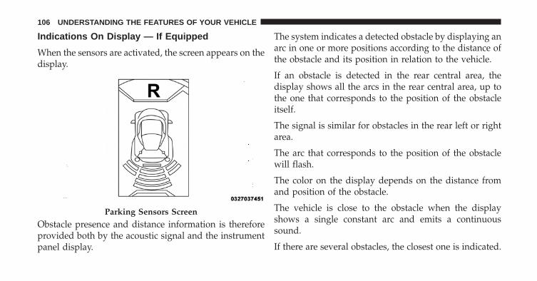
Indications On Display — If Equipped
When the sensors are activated, the screen appears on thedisplay.
Obstacle presence and distance information is thereforeprovided both by the acoustic signal and the instrumentpanel display.
The system indicates a detected obstacle by displaying anarc in one or more positions according to the distance ofthe obstacle and its position in relation to the vehicle.
If an obstacle is detected in the rear central area, thedisplay shows all the arcs in the rear central area, up tothe one that corresponds to the position of the obstacleitself.
The signal is similar for obstacles in the rear left or rightarea.
The arc that corresponds to the position of the obstaclewill flash.
The color on the display depends on the distance fromand position of the obstacle.
The vehicle is close to the obstacle when the displayshows a single constant arc and emits a continuoussound.
If there are several obstacles, the closest one is indicated.
Parking Sensors Screen
106 UNDERSTANDING THE FEATURES OF YOUR VEHICLE
Fault Indication
Parking sensor failures, if any, will be indicated whenreverse is engaged by the switching on of the warn-ing light on the instrument panel together with themessage on the display.
General Warnings
When parking, take the utmost care over obstacles thatmay be above or under the sensor.
Under certain circumstances, objects close to the vehicleare not detected by the system and could therefore causedamage to the vehicle or be damaged themselves.
Some conditions may influence the performance of theparking sensors:
• The presence of ice, snow, mud or multiple layers ofpaint on the sensor surface may cause reduced sensi-tivity of the sensor itself and therefore reduce thesystem performance.
• Mechanical interference (e.g washing the vehicle, rain,strong wind, hail) may cause the sensor to detect anon-existent obstacle (“echo interference”).
• The presence of ultrasonic systems (e.g. pneumaticbrake systems of trucks or pneumatic drills) near thevehicle could alter the signals sent by the sensor.
• The variation in sensor position, caused by variation inride (due to suspension component wear), changingtires, overloaded vehicle, or tuning that lowers thevehicle, for example, may affect parking sensor systemperformance.
3
UNDERSTANDING THE FEATURES OF YOUR VEHICLE 107
NOTE: The sensor must be free from mud, dirt snow orice in order for the system to operate correctly. Be carefulnot to scratch or damage the sensors while cleaning them.Avoid using dry, rough or hard cloths. The sensors must bewashed using clean water, with the addition of car sham-poo if necessary. When using special washing equipmentsuch as high pressure jets or steam cleaning, clean thesensors very quickly keeping the jet more than 4 in (10 cm)away. Also, do not apply stickers to the sensors.
CAUTION!
• The Parking Sensor system is only a parking aidand it is unable to recognize every obstacle, includ-ing small obstacles. Parking curbs might be tem-porarily detected or not detected at all. Obstacleslocated above or below the sensors will not bedetected when they are in close proximity
(Continued)
CAUTION! (Continued)• The vehicle must be driven slowly when using the
Parking Sensor system in order to be able to stop intime when an obstacle is detected. It is recom-mended that the driver looks over his/her shoulderwhen using the Parking Sensor system.
WARNING!
Drivers must be careful when backing up even whenusing the Parking Sensor system. Always check care-fully behind your vehicle, and be sure to check forpedestrians, animals, other vehicles, obstructions, orblind spots before backing up. You are responsiblefor the safety of your surroundings and must con-tinue to pay attention while backing up. Failure to doso can result in serious injury or death.
108 UNDERSTANDING THE FEATURES OF YOUR VEHICLE
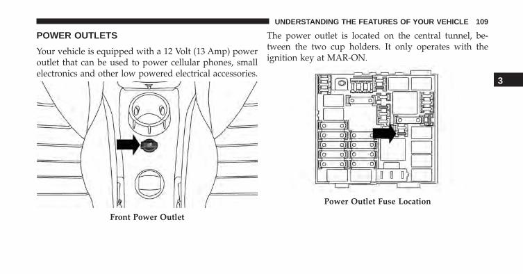
POWER OUTLETS
Your vehicle is equipped with a 12 Volt (13 Amp) poweroutlet that can be used to power cellular phones, smallelectronics and other low powered electrical accessories.
The power outlet is located on the central tunnel, be-tween the two cup holders. It only operates with theignition key at MAR-ON.
Front Power Outlet
Power Outlet Fuse Location
3
UNDERSTANDING THE FEATURES OF YOUR VEHICLE 109
WARNING!
To avoid serious injury or death:• Only devices designed for use in this type of outlet
should be inserted into any 12 Volt outlet.• Do not touch with wet hands.• Close the lid when not in use and while driving the
vehicle.• If this outlet is mishandled, it may cause an electric
shock and failure.
CAUTION!
• Many accessories that can be plugged in drawpower from the vehicle’s battery, even when not inuse (i.e., cellular phones, etc.). Eventually, ifplugged in long enough, the vehicle’s battery willdischarge sufficiently to degrade battery life and/orprevent the engine from starting.
• Accessories that draw higher power (i.e., coolers,vacuum cleaners, lights, etc.) will degrade the bat-tery even more quickly. Only use these intermit-tently and with greater caution.
• After the use of high power draw accessories, orlong periods of the vehicle not being started (withaccessories still plugged in), the vehicle must bedriven a sufficient length of time to allow thegenerator to recharge the vehicle’s battery.
110 UNDERSTANDING THE FEATURES OF YOUR VEHICLE
CAUTION!
• Do not exceed the maximum power of 180 Watts (15Amps) at 12 Volts. If the 180 Watts (15 Amps) powerrating is exceeded, the fuse protecting the systemwill need to be replaced.
• Power outlets are designed for accessory plugsonly. Do not insert any other object in the poweroutlets as this will damage the outlet and blow thefuse. Improper use of the power outlet can causedamage not covered by your New Vehicle LimitedWarranty.
CIGAR LIGHTER AND ASH RECEIVER — IFEQUIPPED
The cigar lighter and ash receiver are located on thecentral tunnel. To activate the cigar lighter, push thebutton down. After a few seconds the button automati-cally returns to its initial position, and the cigar lighter isready for use.
NOTE:
• Always check that the cigar lighter is switched off.
• Do not connect devices with power higher than 180 Wto the socket.
• Do not damage the socket by using unsuitable adap-tors.
3
UNDERSTANDING THE FEATURES OF YOUR VEHICLE 111
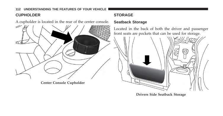
CUPHOLDER
A cupholder is located in the rear of the center console.
STORAGE
Seatback Storage
Located in the back of both the driver and passengerfront seats are pockets that can be used for storage.
Center Console Cupholder
Drivers Side Seatback Storage
112 UNDERSTANDING THE FEATURES OF YOUR VEHICLE
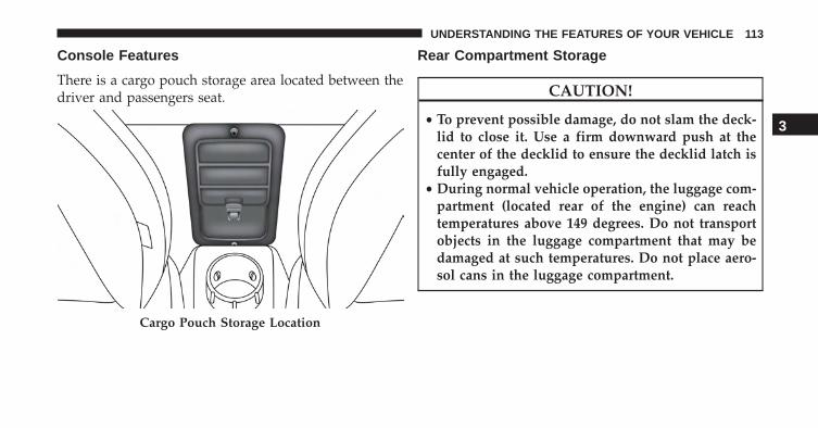
Console Features
There is a cargo pouch storage area located between thedriver and passengers seat.
Rear Compartment Storage
CAUTION!
• To prevent possible damage, do not slam the deck-lid to close it. Use a firm downward push at thecenter of the decklid to ensure the decklid latch isfully engaged.
• During normal vehicle operation, the luggage com-partment (located rear of the engine) can reachtemperatures above 149 degrees. Do not transportobjects in the luggage compartment that may bedamaged at such temperatures. Do not place aero-sol cans in the luggage compartment.
Cargo Pouch Storage Location
3
UNDERSTANDING THE FEATURES OF YOUR VEHICLE 113
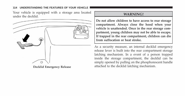
Your vehicle is equipped with a storage area locatedunder the decklid.
WARNING!
Do not allow children to have access to rear storagecompartment. Always close the hood when yourvehicle is unattended. Once in the rear storage com-partment, young children may not be able to escape.If trapped in the rear compartment, children can diefrom suffocation or heat stroke.
As a security measure, an internal decklid emergencyrelease lever is built into the rear compartment storagelatching mechanism. In a event of a person trappedinside the storage compartment, the decklid can besimply opened by pulling on the phosphorescent handleattached to the decklid latching mechanism.Decklid Emergency Release
114 UNDERSTANDING THE FEATURES OF YOUR VEHICLE
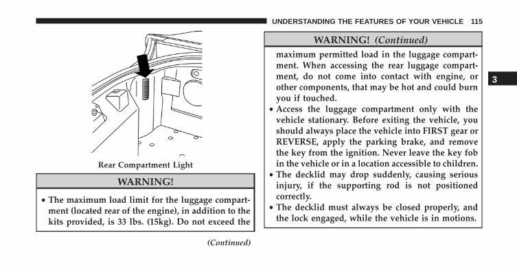
WARNING!
• The maximum load limit for the luggage compart-ment (located rear of the engine), in addition to thekits provided, is 33 lbs. (15kg). Do not exceed the
(Continued)
WARNING! (Continued)maximum permitted load in the luggage compart-ment. When accessing the rear luggage compart-ment, do not come into contact with engine, orother components, that may be hot and could burnyou if touched.
• Access the luggage compartment only with thevehicle stationary. Before exiting the vehicle, youshould always place the vehicle into FIRST gear orREVERSE, apply the parking brake, and removethe key from the ignition. Never leave the key fobin the vehicle or in a location accessible to children.
• The decklid may drop suddenly, causing seriousinjury, if the supporting rod is not positionedcorrectly.
• The decklid must always be closed properly, andthe lock engaged, while the vehicle is in motions.
Rear Compartment Light
3
UNDERSTANDING THE FEATURES OF YOUR VEHICLE 115

UNDERSTANDING YOUR INSTRUMENT PANEL
CONTENTS� INSTRUMENT PANEL FEATURES . . . . . . . . . .118
� INSTRUMENT CLUSTER . . . . . . . . . . . . . . . . .119
� WARNING AND INDICATOR LIGHTS . . . . . . .121▫ Red Telltale Indicator Lights . . . . . . . . . . . . . .122
▫ Yellow Telltale Indicator Lights . . . . . . . . . . . .130
▫ Green Telltale Indicator Lights . . . . . . . . . . . .139
▫ White Telltale Indicator Lights . . . . . . . . . . . .142
▫ Blue Telltale Indicator Lights. . . . . . . . . . . . . .143
� ELECTRONIC VEHICLE INFORMATIONCENTER (EVIC) . . . . . . . . . . . . . . . . . . . . . . .144▫ Electronic Vehicle Information Center (EVIC)
Setup Menu . . . . . . . . . . . . . . . . . . . . . . . . .146
▫ Change Engine Oil Indicator System . . . . . . . .155
▫ Trip Computer . . . . . . . . . . . . . . . . . . . . . . .156
▫ Values Displayed . . . . . . . . . . . . . . . . . . . . .158
� CYBERSECURITY. . . . . . . . . . . . . . . . . . . . . . .160
� RADIO SYSTEM. . . . . . . . . . . . . . . . . . . . . . . .162
� RADIO OPERATION AND MOBILE PHONES . .162
▫ General Information . . . . . . . . . . . . . . . . . . .163
� HEATING AND VENTILATION . . . . . . . . . . . .163
▫ Manual Climate Controls With A/C . . . . . . . .163
4
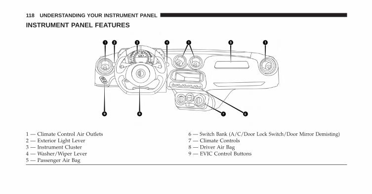
INSTRUMENT PANEL FEATURES
1 — Climate Control Air Outlets 6 — Switch Bank (A/C/Door Lock Switch/Door Mirror Demisting)2 — Exterior Light Lever 7 — Climate Controls3 — Instrument Cluster 8 — Driver Air Bag4 — Washer/Wiper Lever 9 — EVIC Control Buttons5 — Passenger Air Bag
118 UNDERSTANDING YOUR INSTRUMENT PANEL
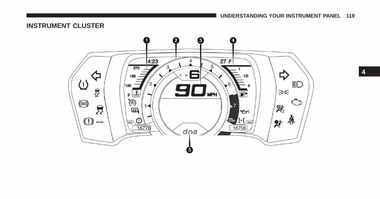
INSTRUMENT CLUSTER
4
UNDERSTANDING YOUR INSTRUMENT PANEL 119
1. Temperature Gauge• The temperature gauge shows engine coolant tem-
perature. Any reading within the normal range indi-cates that the engine cooling system is operatingsatisfactorily.
• The digital gauge will likely indicate a higher tem-perature when driving in hot weather, or up moun-tain grades. It should not be allowed to exceed theupper limits of the normal operating range.
NOTE: Driving with a hot engine cooling system coulddamage your vehicle. The digital warning light mayswitch on (together with a message on the display) toindicate that the coolant temperature is too high; in thiscase, stop the engine and contact a dedicated authorizeddealership.
WARNING!
A hot engine cooling system is dangerous. You orothers could be badly burned by steam or boilingcoolant. You may want to call an authorized dealerfor service if your vehicle overheats. If you decide tolook under the hood yourself, see “Maintaining YourVehicle.” Follow the warnings under the CoolingSystem Pressure Cap paragraph.
2. Tachometer• This gauge measures engine revolutions per minute
(RPM x 1000). Before the pointer reaches the red area,ease up on the accelerator to prevent engine damage.
3. Speedometer• Indicates vehicle speed.
120 UNDERSTANDING YOUR INSTRUMENT PANEL
4. Fuel Gauge• The digital display shows the amount of fuel in the
tank.• The switching on of the digital warning light indi-
cates that 1 – 1.3 gallons of fuel are left in the tank; inthis situation, refuel as soon as possible.
• Do not travel with the fuel tank almost empty; anygaps in fuel delivery could damage the catalyticconverter.
The fuel pump symbol points to the side of thevehicle where the fuel door is located.
5. “Alfa DNA” Driving Mode Indicator• This area of the cluster displays which driving mode
the vehicle is currently in. A letter (d, n, or a)corresponding to the active driving mode (dynamicor race, natural, all weather) and a dedicated mes-sage is shown on the display.
WARNING AND INDICATOR LIGHTS
IMPORTANT: The warning / indicator lights switch onin the instrument panel together with a dedicated mes-sage and/or acoustic signal when applicable. Theseindications are indicative and precautionary and as suchmust not be considered as exhaustive and/or alternativeto the information contained in the Owner Manual,which you are advised to read carefully in all cases.Always refer to the information in this chapter in theevent of a failure indication.
All active telltales will display first if applicable. Thesystem check menu may appear different based uponequipment options and current vehicle status. Sometelltales are optional and may not appear.
4
UNDERSTANDING YOUR INSTRUMENT PANEL 121
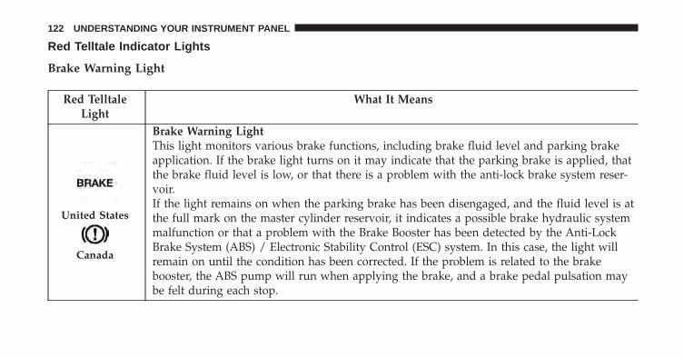
Red Telltale Indicator Lights
Brake Warning Light
Red TelltaleLight
What It Means
United States
Canada
Brake Warning LightThis light monitors various brake functions, including brake fluid level and parking brakeapplication. If the brake light turns on it may indicate that the parking brake is applied, thatthe brake fluid level is low, or that there is a problem with the anti-lock brake system reser-voir.If the light remains on when the parking brake has been disengaged, and the fluid level is atthe full mark on the master cylinder reservoir, it indicates a possible brake hydraulic systemmalfunction or that a problem with the Brake Booster has been detected by the Anti-LockBrake System (ABS) / Electronic Stability Control (ESC) system. In this case, the light willremain on until the condition has been corrected. If the problem is related to the brakebooster, the ABS pump will run when applying the brake, and a brake pedal pulsation maybe felt during each stop.
122 UNDERSTANDING YOUR INSTRUMENT PANEL
The dual brake system provides a reserve braking capac-ity in the event of a failure to a portion of the hydraulicsystem. A leak in either half of the dual brake system isindicated by the Brake Warning Light, which will turn onwhen the brake fluid level in the master cylinder hasdropped below a specified level.
The light will remain on until the cause is corrected.
NOTE: The light may flash momentarily during sharpcornering maneuvers, which change fluid level condi-tions. The vehicle should have service performed, andthe brake fluid level checked.
If brake failure is indicated, immediate repair is necessary.
WARNING!
Driving a vehicle with the red brake light on isdangerous. Part of the brake system may have failed.
(Continued)
WARNING! (Continued)It will take longer to stop the vehicle. You could havea collision. Have the vehicle checked immediately.
Vehicles equipped with the Anti-Lock Brake System(ABS) are also equipped with Electronic Brake ForceDistribution (EBD). In the event of an EBD failure, theBrake Warning Light will turn on along with the ABSLight. Immediate repair to the ABS system is required.
Operation of the Brake Warning Light can be checked byturning the ignition switch from the OFF position to theON/RUN position. The light should illuminate for ap-proximately two seconds. The light should then turn offunless the parking brake is applied or a brake fault isdetected. If the light does not illuminate, have the lightinspected by an authorized dealer.
4
UNDERSTANDING YOUR INSTRUMENT PANEL 123
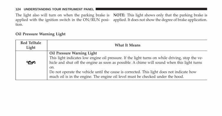
The light also will turn on when the parking brake isapplied with the ignition switch in the ON/RUN posi-tion.
NOTE: This light shows only that the parking brake isapplied. It does not show the degree of brake application.
Oil Pressure Warning Light
Red TelltaleLight
What It Means
Oil Pressure Warning LightThis light indicates low engine oil pressure. If the light turns on while driving, stop the ve-hicle and shut off the engine as soon as possible. A chime will sound when this light turnson.Do not operate the vehicle until the cause is corrected. This light does not indicate howmuch oil is in the engine. The engine oil level must be checked under the hood.
124 UNDERSTANDING YOUR INSTRUMENT PANEL
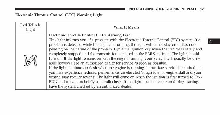
Electronic Throttle Control (ETC) Warning Light
Red TelltaleLight
What It Means
Electronic Throttle Control (ETC) Warning LightThis light informs you of a problem with the Electronic Throttle Control (ETC) system. If aproblem is detected while the engine is running, the light will either stay on or flash de-pending on the nature of the problem. Cycle the ignition key when the vehicle is safely andcompletely stopped and the transmission is placed in the PARK position. The light shouldturn off. If the light remains on with the engine running, your vehicle will usually be driv-able; however, see an authorized dealer for service as soon as possible.If the light continues to flash when the engine is running, immediate service is required andyou may experience reduced performance, an elevated/rough idle, or engine stall and yourvehicle may require towing. The light will come on when the ignition is first turned to ON/RUN and remain on briefly as a bulb check. If the light does not come on during starting,have the system checked by an authorized dealer.
4
UNDERSTANDING YOUR INSTRUMENT PANEL 125
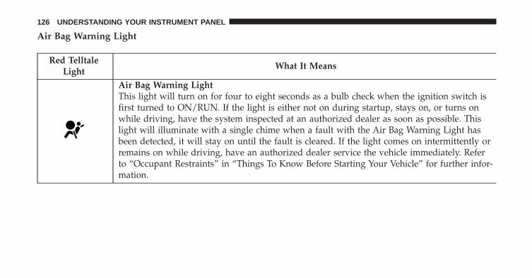
Air Bag Warning Light
Red TelltaleLight
What It Means
Air Bag Warning LightThis light will turn on for four to eight seconds as a bulb check when the ignition switch isfirst turned to ON/RUN. If the light is either not on during startup, stays on, or turns onwhile driving, have the system inspected at an authorized dealer as soon as possible. Thislight will illuminate with a single chime when a fault with the Air Bag Warning Light hasbeen detected, it will stay on until the fault is cleared. If the light comes on intermittently orremains on while driving, have an authorized dealer service the vehicle immediately. Referto “Occupant Restraints” in “Things To Know Before Starting Your Vehicle” for further infor-mation.
126 UNDERSTANDING YOUR INSTRUMENT PANEL
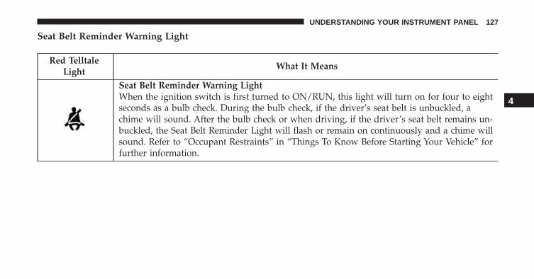
Seat Belt Reminder Warning Light
Red TelltaleLight
What It Means
Seat Belt Reminder Warning LightWhen the ignition switch is first turned to ON/RUN, this light will turn on for four to eightseconds as a bulb check. During the bulb check, if the driver’s seat belt is unbuckled, achime will sound. After the bulb check or when driving, if the driver’s seat belt remains un-buckled, the Seat Belt Reminder Light will flash or remain on continuously and a chime willsound. Refer to “Occupant Restraints” in “Things To Know Before Starting Your Vehicle” forfurther information.
4
UNDERSTANDING YOUR INSTRUMENT PANEL 127
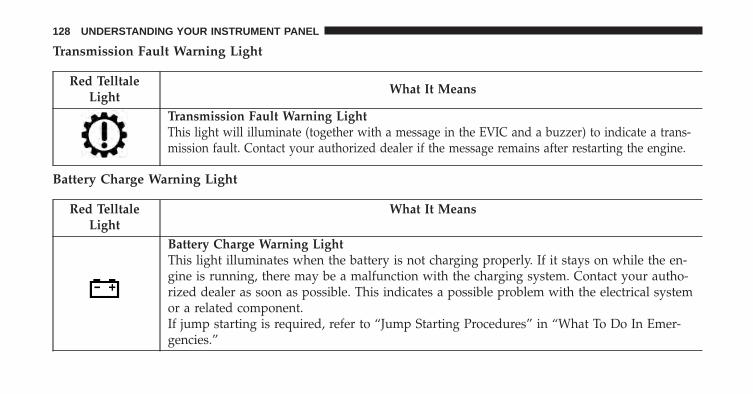
Transmission Fault Warning Light
Red TelltaleLight
What It Means
Transmission Fault Warning LightThis light will illuminate (together with a message in the EVIC and a buzzer) to indicate a trans-mission fault. Contact your authorized dealer if the message remains after restarting the engine.
Battery Charge Warning Light
Red TelltaleLight
What It Means
Battery Charge Warning LightThis light illuminates when the battery is not charging properly. If it stays on while the en-gine is running, there may be a malfunction with the charging system. Contact your autho-rized dealer as soon as possible. This indicates a possible problem with the electrical systemor a related component.If jump starting is required, refer to “Jump Starting Procedures” in “What To Do In Emer-gencies.”
128 UNDERSTANDING YOUR INSTRUMENT PANEL
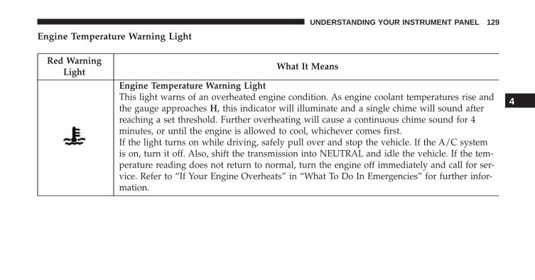
Engine Temperature Warning Light
Red WarningLight
What It Means
Engine Temperature Warning LightThis light warns of an overheated engine condition. As engine coolant temperatures rise andthe gauge approaches H, this indicator will illuminate and a single chime will sound afterreaching a set threshold. Further overheating will cause a continuous chime sound for 4minutes, or until the engine is allowed to cool, whichever comes first.If the light turns on while driving, safely pull over and stop the vehicle. If the A/C systemis on, turn it off. Also, shift the transmission into NEUTRAL and idle the vehicle. If the tem-perature reading does not return to normal, turn the engine off immediately and call for ser-vice. Refer to “If Your Engine Overheats” in “What To Do In Emergencies” for further infor-mation.
4
UNDERSTANDING YOUR INSTRUMENT PANEL 129
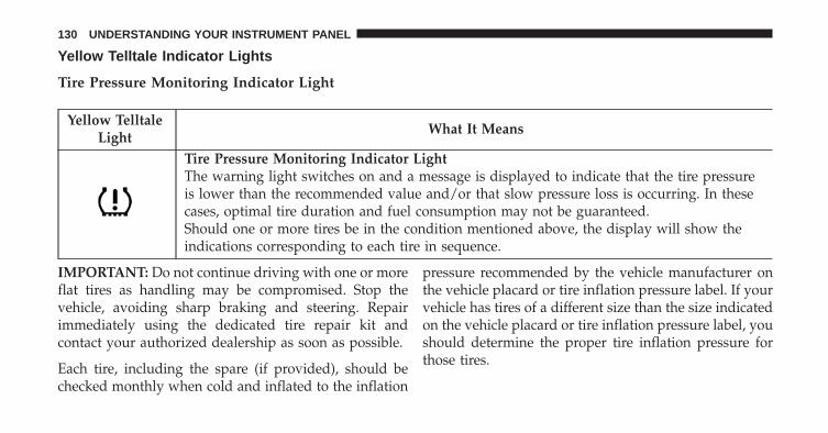
Yellow Telltale Indicator Lights
Tire Pressure Monitoring Indicator Light
Yellow TelltaleLight
What It Means
Tire Pressure Monitoring Indicator LightThe warning light switches on and a message is displayed to indicate that the tire pressureis lower than the recommended value and/or that slow pressure loss is occurring. In thesecases, optimal tire duration and fuel consumption may not be guaranteed.Should one or more tires be in the condition mentioned above, the display will show theindications corresponding to each tire in sequence.
IMPORTANT: Do not continue driving with one or moreflat tires as handling may be compromised. Stop thevehicle, avoiding sharp braking and steering. Repairimmediately using the dedicated tire repair kit andcontact your authorized dealership as soon as possible.
Each tire, including the spare (if provided), should bechecked monthly when cold and inflated to the inflation
pressure recommended by the vehicle manufacturer onthe vehicle placard or tire inflation pressure label. If yourvehicle has tires of a different size than the size indicatedon the vehicle placard or tire inflation pressure label, youshould determine the proper tire inflation pressure forthose tires.
130 UNDERSTANDING YOUR INSTRUMENT PANEL
As an added safety feature, your vehicle has beenequipped with a Tire Pressure Monitoring System(TPMS) that illuminates a low tire pressure telltale whenone or more of your tires is significantly under-inflated.Accordingly, when the low tire pressure telltale illumi-nates, you should stop and check your tires as soon aspossible and inflate them to the proper pressure. Drivingon a significantly under-inflated tire causes the tire tooverheat and can lead to tire failure. Under-inflation alsoreduces fuel efficiency and tire tread life, and may affectthe vehicle’s handling and stopping ability.
Please note that the TPMS is not a substitute for propertire maintenance, and it is the driver’s responsibility tomaintain correct tire pressure, even if under-inflation hasnot reached the level to trigger illumination of the TPMSlow tire pressure telltale.
Your vehicle has also been equipped with a TPMSmalfunction indicator to indicate when the system is not
operating properly. The TPMS malfunction indicator iscombined with the low tire pressure telltale. When thesystem detects a malfunction, the telltale will flash forapproximately one minute and then remain continuouslyilluminated. This sequence will continue upon subse-quent vehicle start-ups as long as the malfunction exists.When the malfunction indicator is illuminated, the sys-tem may not be able to detect or signal low tire pressureas intended. TPMS malfunctions may occur for a varietyof reasons, including the installation of replacement oralternate tires or wheels on the vehicle that prevent theTPMS from functioning properly. Always check theTPMS malfunction telltale after replacing one or moretires or wheels on your vehicle, to ensure that thereplacement or alternate tires and wheels allow the TPMSto continue to function properly.
4
UNDERSTANDING YOUR INSTRUMENT PANEL 131
CAUTION!
The TPMS has been optimized for the originalequipment tires and wheels. TPMS pressures andwarning have been established for the tire sizeequipped on your vehicle. Undesirable system opera-tion or sensor damage may result when using re-placement equipment that is not of the same size,
(Continued)
CAUTION! (Continued)type, and/or style. Aftermarket wheels can causesensor damage. Using aftermarket tire sealants maycause the Tire Pressure Monitoring System (TPMS)sensor to become inoperable. After using an after-market tire sealant it is recommended that you takeyour vehicle to an authorized dealership to have yoursensor function checked.
132 UNDERSTANDING YOUR INSTRUMENT PANEL
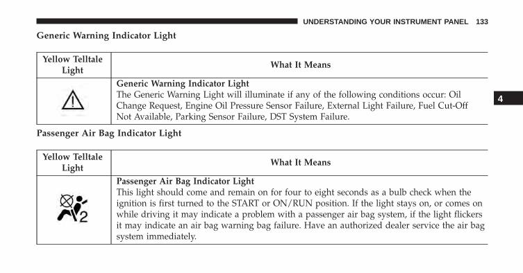
Generic Warning Indicator Light
Yellow TelltaleLight
What It Means
Generic Warning Indicator LightThe Generic Warning Light will illuminate if any of the following conditions occur: OilChange Request, Engine Oil Pressure Sensor Failure, External Light Failure, Fuel Cut-OffNot Available, Parking Sensor Failure, DST System Failure.
Passenger Air Bag Indicator Light
Yellow TelltaleLight
What It Means
Passenger Air Bag Indicator LightThis light should come and remain on for four to eight seconds as a bulb check when theignition is first turned to the START or ON/RUN position. If the light stays on, or comes onwhile driving it may indicate a problem with a passenger air bag system, if the light flickersit may indicate an air bag warning bag failure. Have an authorized dealer service the air bagsystem immediately.
4
UNDERSTANDING YOUR INSTRUMENT PANEL 133
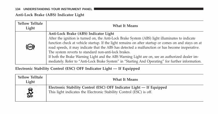
Anti-Lock Brake (ABS) Indicator Light
Yellow TelltaleLight
What It Means
Anti-Lock Brake (ABS) Indicator LightAfter the ignition is turned on, the Anti-Lock Brake System (ABS) light illuminates to indicatefunction check at vehicle startup. If the light remains on after startup or comes on and stays on atroad speeds, it may indicate that the ABS has detected a malfunction or has become inoperative.The system reverts to standard non-anti-lock brakes.If both the Brake Warning Light and the ABS Warning Light are on, see an authorized dealer im-mediately. Refer to “Anti-Lock Brake System” in “Starting And Operating” for further information.
Electronic Stability Control (ESC) OFF Indicator Light — If Equipped
Yellow TelltaleLight
What It Means
Electronic Stability Control (ESC) OFF Indicator Light — If EquippedThis light indicates the Electronic Stability Control (ESC) is off.
134 UNDERSTANDING YOUR INSTRUMENT PANEL
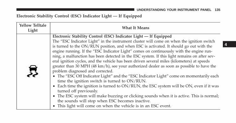
Electronic Stability Control (ESC) Indicator Light — If Equipped
Yellow TelltaleLight
What It Means
Electronic Stability Control (ESC) Indicator Light — If EquippedThe “ESC Indicator Light” in the instrument cluster will come on when the ignition switchis turned to the ON/RUN position, and when ESC is activated. It should go out with theengine running. If the “ESC Indicator Light” comes on continuously with the engine run-ning, a malfunction has been detected in the ESC system. If this light remains on after sev-eral ignition cycles, and the vehicle has been driven several miles (kilometers) at speedsgreater than 30 MPH (48 km/h), see your authorized dealer as soon as possible to have theproblem diagnosed and corrected.• The “ESC Off Indicator Light” and the “ESC Indicator Light” come on momentarily each
time the ignition switch is turned to ON/RUN.• Each time the ignition is turned to ON/RUN, the ESC system will be ON, even if it was
turned off previously.• The ESC system will make buzzing or clicking sounds when it is active. This is normal;
the sounds will stop when ESC becomes inactive.• This light will come on when the vehicle is in an ESC event.
4
UNDERSTANDING YOUR INSTRUMENT PANEL 135
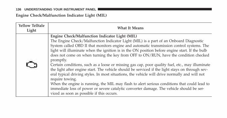
Engine Check/Malfunction Indicator Light (MIL)
Yellow TelltaleLight
What It Means
Engine Check/Malfunction Indicator Light (MIL)The Engine Check/Malfunction Indicator Light (MIL) is a part of an Onboard DiagnosticSystem called OBD II that monitors engine and automatic transmission control systems. Thelight will illuminate when the ignition is in the ON position before engine start. If the bulbdoes not come on when turning the key from OFF to ON/RUN, have the condition checkedpromptly.Certain conditions, such as a loose or missing gas cap, poor quality fuel, etc., may illuminatethe light after engine start. The vehicle should be serviced if the light stays on through sev-eral typical driving styles. In most situations, the vehicle will drive normally and will notrequire towing.When the engine is running, the MIL may flash to alert serious conditions that could lead toimmediate loss of power or severe catalytic converter damage. The vehicle should be ser-viced as soon as possible if this occurs.
136 UNDERSTANDING YOUR INSTRUMENT PANEL
CAUTION!
Prolonged driving with the Malfunction IndicatorLight (MIL) on could cause damage to the enginecontrol system. It also could affect fuel economy anddriveability. If the MIL is flashing, severe catalyticconverter damage and power loss will soon occur.Immediate service is required.
WARNING!
A malfunctioning catalytic converter, as referencedabove, can reach higher temperatures than in normaloperating conditions. This can cause a fire if youdrive slowly or park over flammable substances suchas dry plants, wood, cardboard, etc. This could resultin death or serious injury to the driver, occupants orothers.
4
UNDERSTANDING YOUR INSTRUMENT PANEL 137
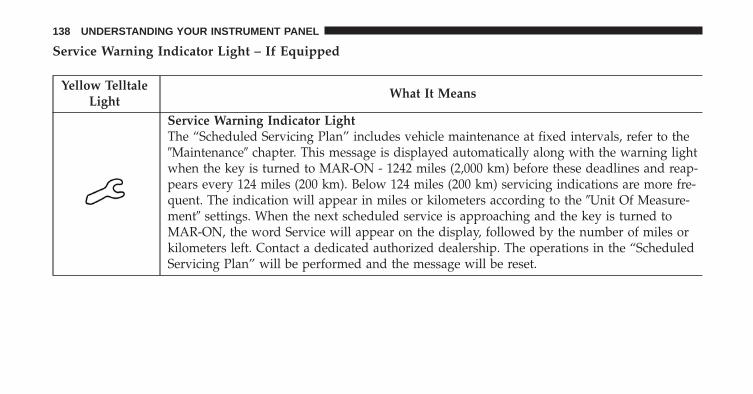
Service Warning Indicator Light – If Equipped
Yellow TelltaleLight
What It Means
Service Warning Indicator LightThe “Scheduled Servicing Plan” includes vehicle maintenance at fixed intervals, refer to the�Maintenance� chapter. This message is displayed automatically along with the warning lightwhen the key is turned to MAR-ON - 1242 miles (2,000 km) before these deadlines and reap-pears every 124 miles (200 km). Below 124 miles (200 km) servicing indications are more fre-quent. The indication will appear in miles or kilometers according to the �Unit Of Measure-ment� settings. When the next scheduled service is approaching and the key is turned toMAR-ON, the word Service will appear on the display, followed by the number of miles orkilometers left. Contact a dedicated authorized dealership. The operations in the “ScheduledServicing Plan” will be performed and the message will be reset.
138 UNDERSTANDING YOUR INSTRUMENT PANEL
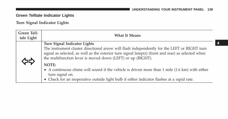
Green Telltale Indicator Lights
Turn Signal Indicator Lights
Green Tell-tale Light
What It Means
Turn Signal Indicator LightsThe instrument cluster directional arrow will flash independently for the LEFT or RIGHT turnsignal as selected, as well as the exterior turn signal lamp(s) (front and rear) as selected whenthe multifunction lever is moved down (LEFT) or up (RIGHT).
NOTE:• A continuous chime will sound if the vehicle is driven more than 1 mile (1.6 km) with either
turn signal on.• Check for an inoperative outside light bulb if either indicator flashes at a rapid rate.
4
UNDERSTANDING YOUR INSTRUMENT PANEL 139
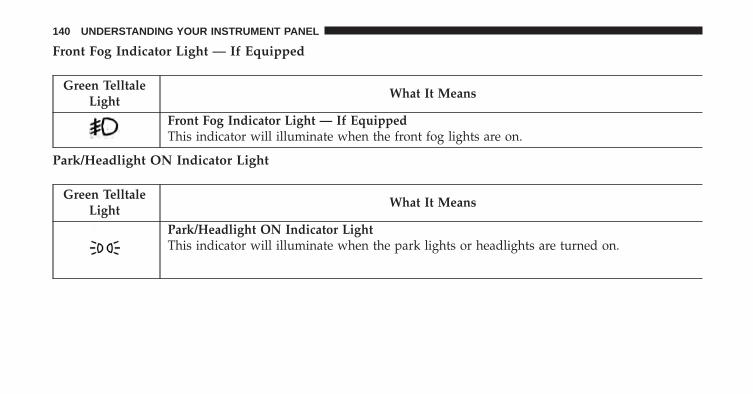
Front Fog Indicator Light — If Equipped
Green TelltaleLight
What It Means
Front Fog Indicator Light — If EquippedThis indicator will illuminate when the front fog lights are on.
Park/Headlight ON Indicator Light
Green TelltaleLight
What It Means
Park/Headlight ON Indicator LightThis indicator will illuminate when the park lights or headlights are turned on.
140 UNDERSTANDING YOUR INSTRUMENT PANEL
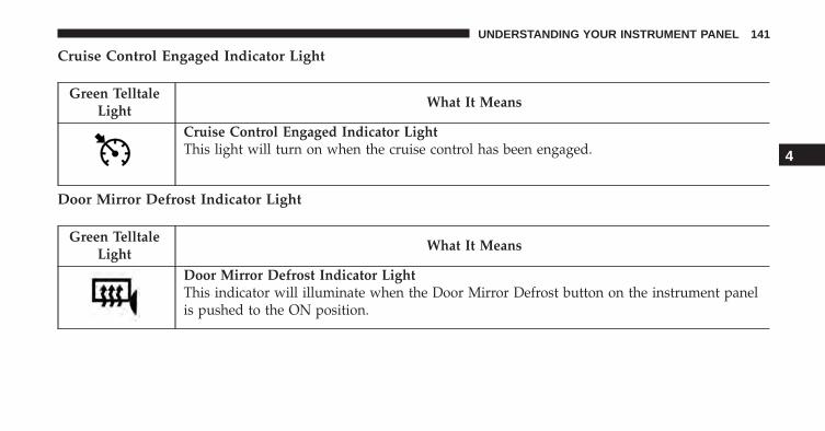
Cruise Control Engaged Indicator Light
Green TelltaleLight
What It Means
Cruise Control Engaged Indicator LightThis light will turn on when the cruise control has been engaged.
Door Mirror Defrost Indicator Light
Green TelltaleLight
What It Means
Door Mirror Defrost Indicator LightThis indicator will illuminate when the Door Mirror Defrost button on the instrument panelis pushed to the ON position.
4
UNDERSTANDING YOUR INSTRUMENT PANEL 141
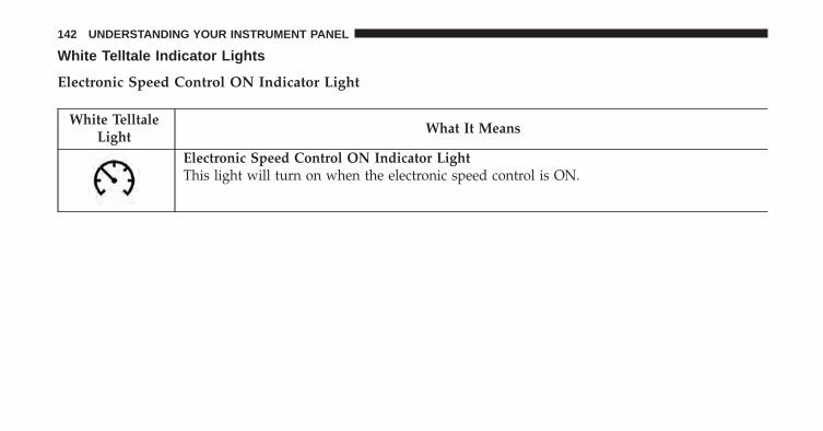
White Telltale Indicator Lights
Electronic Speed Control ON Indicator Light
White TelltaleLight
What It Means
Electronic Speed Control ON Indicator LightThis light will turn on when the electronic speed control is ON.
142 UNDERSTANDING YOUR INSTRUMENT PANEL
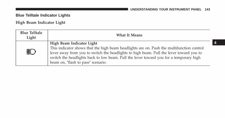
Blue Telltale Indicator Lights
High Beam Indicator Light
Blue TelltaleLight
What It Means
High Beam Indicator LightThis indicator shows that the high beam headlights are on. Push the multifunction controllever away from you to switch the headlights to high beam. Pull the lever toward you toswitch the headlights back to low beam. Pull the lever toward you for a temporary highbeam on, �flash to pass� scenario.
4
UNDERSTANDING YOUR INSTRUMENT PANEL 143
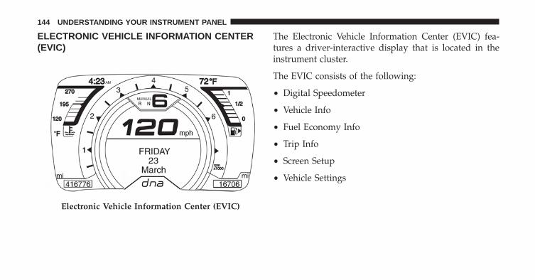
ELECTRONIC VEHICLE INFORMATION CENTER(EVIC)
The Electronic Vehicle Information Center (EVIC) fea-tures a driver-interactive display that is located in theinstrument cluster.
The EVIC consists of the following:
• Digital Speedometer
• Vehicle Info
• Fuel Economy Info
• Trip Info
• Screen Setup
• Vehicle Settings
Electronic Vehicle Information Center (EVIC)
144 UNDERSTANDING YOUR INSTRUMENT PANEL
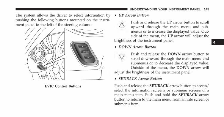
The system allows the driver to select information bypushing the following buttons mounted on the instru-ment panel to the left of the steering column:
• UP Arrow Button
Push and release the UP arrow button to scrollupward through the main menu and sub-menus or to increase the displayed value. Out-side of the menu, the UP arrow will adjust the
brightness of the instrument panel.
• DOWN Arrow Button
Push and release the DOWN arrow button toscroll downward through the main menu andsubmenus or to decrease the displayed value.Outside of the menu, the DOWN arrow will
adjust the brightness of the instrument panel.
• SET/BACK Arrow Button
Push and release the SET/BACK arrow button to access/select the information screens or submenu screens of amain menu item. Push and hold the SET/BACK arrowbutton to return to the main menu from an info screen orsubmenu item.
EVIC Control Buttons
4
UNDERSTANDING YOUR INSTRUMENT PANEL 145
Electronic Vehicle Information Center (EVIC)Setup Menu
The menu comprises a series of functions arranged in acycle. Push the UP and DOWN arrow buttons toaccess the different options and settings (setup).
The setup menu can be activated by pushing the SET/BACK button. Single push on the UP or DOWN
arrow button will scroll through the setup menuoptions. The menu includes the following functions:
• Menu
• Speed Buzzer
• Trip B/Data
• Set Time
• Set Date
• Autoclose
• Units
• Language
• Buzzer Volume
• Service
• Daylights (D.R.L.) – If Equipped
• Exit Menu
Selecting An Option Of The Main Menu WithoutSubmenu
1. Briefly push the SET/BACK button to select the mainmenu option to set.
2. Push the UP or DOWN arrow button (by asingle push) to select the new setting.
3. Briefly push the SET/BACK button to store the newsetting and go back to the main menu option previ-ously selected.
146 UNDERSTANDING YOUR INSTRUMENT PANEL
Selecting An Option Of The Main Menu With Submenu
1. Briefly push the SET/BACK button to display the firstsubmenu option.
2. Push the UP or DOWN arrow button (by asingle push) to scroll through all the submenu options.
3. Briefly push the SET/BACK button to select the dis-played submenu option and to open the relevant setupmenu.
4. Push the UP or DOWN arrow button (by asingle push) to select the new setting for thissubmenu option.
5. Briefly push the SET/BACK button to store the newsetting and go back to the previously selected sub-menu option.
6. Push and hold the SET/BACK button to return to themain menu (short hold) or the main screen (longer hold).
Speed Buzzer (Speed Limit)
With this function, it is possible to set the vehicle speedlimit (MPH or km/h) to immediately alert the driverwhen the set limit is exceeded.
To set the speed limit, proceed as follows:
1. Briefly push the SET/BACK button. The display willshow the message (Speed Buzzer).
2. Push and release the UP or DOWN arrowbutton to select speed limit activation (On) ordeactivation (Off).
3. When the function is activated (On), briefly push theSET/BACK button to display the previously set speed.Pushing the UP or DOWN arrow buttonsselects the speed limit. Push SET/BACK to confirmselection.
4
UNDERSTANDING YOUR INSTRUMENT PANEL 147
NOTE: The setting can be increased or decreased by 5MPH or km/h each time the UP or DOWN arrowbutton is pushed for speed settings above 20 MPH(32 km/h). To increase or decrease the set speedrapidly, push and hold the UP or DOWN arrowbutton. Save the setting by briefly pushing the buttonwhen you approach the required setting.
• Briefly push the SET/BACK button to go back to themenu screen, or push and hold the SET/BACK button(approximately one second) to go back to the mainscreen without storing the settings.
To cancel the setting, proceed as follows:
1. Briefly push the SET/BACK button. “On” will display.
2. Push and release the DOWN button. “Off” willdisplay.
3. Briefly push the SET/BACK button to go back to themenu screen, or push and hold the SET/BACK button(approximately one second) to go back to the mainscreen without storing the settings.
Trip B Activation
Through this option, it is possible to activate (On) ordeactivate (Off) the Trip B (partial trip) display.
For further information, see “Trip Computer.”
For activation/deactivation, proceed as follows:
1. Briefly push the SET/BACK button. “On” or “Off”will display in the EVIC (according to previous set-ting).
2. Push and release the UP or DOWN arrowbutton to select the setting and once selected a beepwill occur to signal the setting is saved.
148 UNDERSTANDING YOUR INSTRUMENT PANEL
3. Briefly push the SET/BACK button to go back to themenu screen, or push and hold the SET/BACK button(approximately one second) to go back to the mainscreen without storing the settings.
Set Time
This function may be used to set the clock through twosub-menu items: “Time” and “Mode.”
Proceed as follows:
1. Briefly push the SET/BACK button. The display willshow the two sub-menu items “Time” and “Mode.”
2. Push and release the UP or DOWN arrowbutton to navigate the two sub-menu items.
3. Select the required option and then push the SET/BACK button.
4. When accessing the “Time” sub-menu item, brieflypush the SET/BACK button and “hours” will flash onthe display.
5. Push and release the UP or DOWN arrowbutton for setting.
6. Briefly push the SET/BACK button and “minutes”will flash on the display.
7. Push and release the UP or DOWN arrowbutton for setting.
4
UNDERSTANDING YOUR INSTRUMENT PANEL 149
NOTE:
• The setting will increase or decrease by one unit eachtime the UP or DOWN arrow button ispushed. Push and hold the button to increase/decrease the setting rapidly. Save the setting bybriefly pushing the button when you approach therequired setting.
• Briefly push the SET/BACK button to return to the“Time” sub-function.
• When accessing the “Mode” submenu, briefly pushthe SET/BACK button. The previously set displayformat will flash on the display.
• Push and release the UP or DOWN arrowbutton to select “24h” or “12h.”
When you have selected the required settings, brieflypush the SET/BACK button to go back to the Time, Mode
sub-menu screen, or push and hold the SET/BACKbutton (approximately one second) to go back to themain screen without storing the settings.
Set Date
This function may be used to set the date (day - month -year).
To change the date, proceed as follows:
1. Briefly push the SET/BACK button and “year” willflash on the display.
2. Push and release the UP or DOWN arrowbutton for setting.
3. Briefly push the SET/BACK button and “month” willflash on the display.
4. Push and release the UP or DOWN arrowbutton for setting.
150 UNDERSTANDING YOUR INSTRUMENT PANEL
5. Briefly push the SET/BACK button and “day” willflash on the display.
6. Push and release the UP or DOWN button forsetting.
NOTE: The setting will increase or decrease by one uniteach time the UP or DOWN arrow button ispushed. Push and hold the UP or DOWN arrowbutton to increase/decrease the setting rapidly. Savethe setting by briefly pushing the button when youapproach the required setting.
• Briefly push the SET/BACK button to go back to themenu screen, or push and hold the SET/BACK button(approximately one second) to go back to the mainscreen without storing the settings.
Autoclose
With this function active, the doors will automaticallylock at when the vehicle’s speed exceeds 12 MPH(20 km/h).
To change the setting, proceed as follows:
1. Briefly push the SET/BACK button “On” or “Off” willflash on the display (according to the previous set-ting).
2. Push and release the UP or DOWN arrowbutton for setting.
3. Briefly push the SET/BACK button to go back to themenu screen, or push and hold the SET/BACK button(approximately one second) to go back to the mainscreen without storing the settings.
4
UNDERSTANDING YOUR INSTRUMENT PANEL 151
Units (Set Units)
This function may be used to set the measurement unit inthree submenus: “Distance,” “Temperature” and “FuelEconomy.”
To set the required unit, proceed as follows:
1. Briefly push the SET/BACK button to display thethree sub-menus.
2. Push and release the UP or DOWN arrowbutton to navigate the three sub-menus.
3. Select the required sub-menu and then briefly pushthe SET/BACK button.
4. When accessing the “Distance” submenu, briefly pushthe SET/BACK button. Either “mi” or “km” willappear on the display (according to the previoussetting).
5. Push and release the UP or DOWN arrowbutton for setting.
6. Briefly push the SET/BACK button to return to thesub-menu.
7. When accessing the “Fuel Economy” submenu, brieflypush the SET/BACK button. Either “mpg,” “km/l ” or“l/100km” will appear on the display (according tothe previous setting).
If the distance unit set is “mi,” the fuel economy unit willbe displayed in “mpg.”
If the distance unit set is “km,” the fuel economy unit willbe displayed in either km/l or l/100km.
1. Push and release the UP or DOWN arrowbutton for setting.
2. Briefly push the SET/BACK button to return to thesub-menu.
152 UNDERSTANDING YOUR INSTRUMENT PANEL
3. When accessing the “Temperature” submenu, brieflypush the SET/BACK button. Either “°F” or “°C” willappear on the display (according to the previous setting).
4. Push and release the UP or DOWN arrowbutton for setting.
5. Briefly push the SET/BACK button to return to thesub-menu.
When you have made the required settings, briefly pushthe SET/BACK button to go back to the sub-menu screen,or push and hold the SET/BACK button (approximatelyone second) to go back to the main screen without storingthe settings.
Language (Selecting The Language)
The messages can be displayed in the following lan-guages: Italian, English (USA), German, Portuguese,Spanish, French, Chinese, Russian, and Mexican.
To set the required language, proceed as follows:1. Briefly push the SET/BACK button. The previously
set “language” will flash on the display.
2. Push and release the UP or DOWN arrowbutton for setting.
3. Briefly push the SET/BACK button to go back to themenu screen, or push and hold the SET/BACK button(approximately one second) to go back to the mainscreen without storing the settings.
Buzzer Volume (Adjusting The Failure/WarningBuzzer Volume)
With this function, the volume of the buzzer accompany-ing any failure/warning indication can be adjusted toone of eight volume levels.
To adjust the volume, proceed as follows:
1. Briefly push the SET/BACK button. The previouslyset volume “level” will flash on the display.
4
UNDERSTANDING YOUR INSTRUMENT PANEL 153
2. Push and release the UP or DOWN arrowbutton for setting.
3. Briefly push the SET/BACK button to go back to themenu screen, or push and hold the SET/BACK button(approximately one second) to go back to the mainscreen without storing the settings.
Service (Scheduled Servicing) — If Equipped
With this function, it is possible to view infor-mation on mileage intervals for servicing.
To obtain this information, proceed as follows:
Push the SET/BACK button briefly. The display showsthe service interval in miles (mi) or kilometers (km)according to the previous setting (see the �Unit OfMeasurement� paragraph).
Briefly push the SET/BACK button to go back to themenu screen or hold the button down to go back to thestandard screen.
NOTE: The “Scheduled Servicing Plan” includes vehiclemaintenance at fixed intervals, refer to the �Maintenance�chapter. This message is displayed automatically alongwith the warning light when the key is turned toMAR-ON - 1242 miles (2,000 km) before these dead-lines and reappears every 124 miles (200 km). Below124 miles (200 km) servicing indications are morefrequent. The indication will appear in miles or kilo-meters according to the �Unit Of Measurement� set-tings. When the next scheduled service is approachingand the key is turned to MAR-ON, the word Servicewill appear on the display, followed by the number ofmiles or kilometers left. Contact a dedicated AlfaRomeo Dealership. The operations in the “ScheduledServicing Plan” will be performed and the messagewill be reset.
154 UNDERSTANDING YOUR INSTRUMENT PANEL
Daytime Running Lamps
This function may be used to activate/deactivate theDaytime Running Lamps.
Proceed as follows to switch this function on or off:
1. Briefly push the SET/BACK button to display thethree submenus.
2. Briefly push the SET/BACK button. “On” or “Off”will flash on the display (according to previous set-ting).
3. Push and release the UP or DOWN arrowbutton for setting.
4. Briefly push the SET/BACK button to go back to themenu screen, or push and hold the button (approxi-mately one second) to go back to the main screenwithout storing the settings.
Exit Menu
This function closes the initial menu screen.
Briefly push the SET/BACK button to go back to themain screen.
Push and release the UP arrow button to return tothe first menu option (Speed Buzzer).
Push and release the DOWN arrow button to returnto the last menu option (Daylights).
Change Engine Oil Indicator System
Your vehicle is equipped with an engine oilchange indicator system. The “Change Engine Oil” mes-sage will flash in the EVIC display for approximately 10seconds and the Oil Pressure Warning Light will illumi-nate. The “Change Engine Oil” message in the EVIC andthe Oil Pressure Warning Light will turn off after ap-proximately 10 seconds.
4
UNDERSTANDING YOUR INSTRUMENT PANEL 155
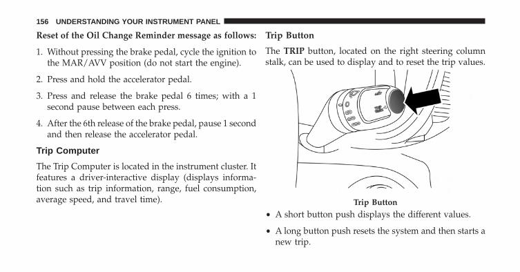
Reset of the Oil Change Reminder message as follows:
1. Without pressing the brake pedal, cycle the ignition tothe MAR/AVV position (do not start the engine).
2. Press and hold the accelerator pedal.
3. Press and release the brake pedal 6 times; with a 1second pause between each press.
4. After the 6th release of the brake pedal, pause 1 secondand then release the accelerator pedal.
Trip Computer
The Trip Computer is located in the instrument cluster. Itfeatures a driver-interactive display (displays informa-tion such as trip information, range, fuel consumption,average speed, and travel time).
Trip Button
The TRIP button, located on the right steering columnstalk, can be used to display and to reset the trip values.
• A short button push displays the different values.
• A long button push resets the system and then starts anew trip.
Trip Button
156 UNDERSTANDING YOUR INSTRUMENT PANEL
Trip Functions
Both trip functions are resettable (reset — start of newtrip).
“Trip A” can be used to display the figures relating to:
• Range
• Average Fuel Consumption
• Travel Distance
• Current Fuel Consumption
• Average speed
• Travel time
“Trip B” can be used to display the figures relating to:
• Average Fuel Consumption
• Travel Distance
• Average speed
• Travel time
“Current Trip” can be used to display the figures relating to:
NOTE: “Trip B” functions may be excluded (see “TripB Data”). “Range” and “Instantaneous consumption”cannot be reset.
New Trip
To reset:
• Push and hold the TRIP button to reset the systemmanually.
• When the “Trip distance” reaches 99999.9 miles orkilometers or when the “Travel time” reaches 999.59(999 hours and 59 minutes), the system is reset auto-matically.
4
UNDERSTANDING YOUR INSTRUMENT PANEL 157
• Disconnecting/Reconnecting the battery resets thesystem.
NOTE: If the reset operation occurs in the presence ofthe screens concerning Trip A or Trip B, only the infor-mation associated with Trip A or Trip B functions will bereset.
Start Of Trip Procedure
With the ignition on, push and hold the TRIP button forover one second to reset.
Exit Trip
To exit the Trip function, wait until all the values havebeen displayed or hold the MENU button for longer thanone second.
Briefly push and release the MENU button to go back tothe menu screen or push and hold the MENU (approxi-mately one second) to go back to the main screen withoutstoring settings.
Values Displayed
Indications On Display
Each time a value is selected, the following information isshown in the EVIC:• “Trip A” or “Trip B” location(s)• Name, value and unit of measure of the selected value
(e.g. �Range 520 mi�).
158 UNDERSTANDING YOUR INSTRUMENT PANEL
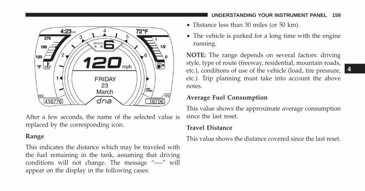
After a few seconds, the name of the selected value isreplaced by the corresponding icon.
Range
This indicates the distance which may be traveled withthe fuel remaining in the tank, assuming that drivingconditions will not change. The message “----” willappear on the display in the following cases:
• Distance less than 30 miles (or 50 km).
• The vehicle is parked for a long time with the enginerunning.
NOTE: The range depends on several factors: drivingstyle, type of route (freeway, residential, mountain roads,etc.), conditions of use of the vehicle (load, tire pressure,etc.). Trip planning must take into account the abovenotes.
Average Fuel Consumption
This value shows the approximate average consumptionsince the last reset.
Travel Distance
This value shows the distance covered since the last reset.
4
UNDERSTANDING YOUR INSTRUMENT PANEL 159
Current Fuel Consumption
This indicates the fuel consumption. The value is con-stantly updated. The message “----” will appear on thedisplay if the vehicle is parked with the engine running.
Average Speed
This value shows the vehicle’s average speed as a func-tion of the overall time elapsed since the last reset.
Travel Time
This value shows the time elapsed since the last reset.
Tire Pressure Values
This screen will display OK at each Tire Pressure Moni-toring sensor. Refer to “Tire Pressure Monitoring System”in “Starting And Operating.”
CYBERSECURITY
Your vehicle may be a connected vehicle and may beequipped with both wired and wireless networks. Thesenetworks allow your vehicle to send and receive infor-mation. This information allows systems and features inyour vehicle to function properly.
Your vehicle may be equipped with certain securityfeatures to reduce the risk of unauthorized and unlawfulaccess to vehicle systems and wireless communications.Vehicle software technology continues to evolve overtime and FCA US LLC, working with its suppliers,evaluates and takes appropriate steps as needed. Similarto a computer or other devices, your vehicle may requiresoftware updates to improve the usability and perfor-mance of your systems or to reduce the potential risk ofunauthorized and unlawful access to your vehicle sys-tems.
160 UNDERSTANDING YOUR INSTRUMENT PANEL
The risk of unauthorized and unlawful access to yourvehicle systems may still exist, even if the most recentversion of vehicle software (such as Uconnect software) isinstalled.
WARNING!
• It is not possible to know or to predict all of thepossible outcomes if your vehicle’s systems arebreached. It may be possible that vehicle systems,including safety related systems, could be im-paired or a loss of vehicle control could occur thatmay result in an accident involving serious injuryor death.
• ONLY insert media (e.g., USB, SD card, or CD) intoyour vehicle if it came from a trusted source. Mediaof unknown origin could possibly contain mali-cious software, and if installed in your vehicle, it
(Continued)
WARNING! (Continued)may increase the possibility for vehicle systems tobe breached.
• As always, if you experience unusual vehicle be-havior, take your vehicle to your nearest authorizeddealer immediately.
NOTE:
• FCA or your dealer may contact you directly regardingsoftware updates.
• To help further improve vehicle security and minimizethe potential risk of a security breach, vehicle ownersshould:• Routinely check www.driveuconnect.com/software-
update to learn about available Uconnect softwareupdates.
• Only connect and use trusted media devices (e.g.personal mobile phones, USBs, CDs).
4
UNDERSTANDING YOUR INSTRUMENT PANEL 161
Privacy of any wireless and wired communications can-not be assured. Third parties may unlawfully interceptinformation and private communications without yourconsent. For further information, refer to “Onboard Di-agnostic System (OBD II) Cybersecurity” in “MaintainingYour Vehicle”.
RADIO SYSTEM
The radio system consists of:
• Supply cables for radio, speakers and aerial
• Radio
• Antenna located on the inside of the front fascia
• Two tweeter speakers with 6 inch (38 mm) diameterand two mid-woofer speakers with 20 inch (130 mm)diameter, fitted on the doors
NOTE: Be sure to press the RESET button when using theunit for the first time, after changing the vehicle battery,or using the battery disconnect (anytime the vehicle losespower).
For further information on radio functions and use, referto the dedicated Supplement attached to the On-BoardDocumentation.
RADIO OPERATION AND MOBILE PHONES
Under certain conditions, the mobile phone being on inyour vehicle can cause erratic or noisy performance fromyour radio. This condition may be lessened or eliminatedby relocating the mobile phone antenna. This condition isnot harmful to the radio. If your radio performance doesnot satisfactorily “clear” by the repositioning of theantenna, it is recommended that the radio volume beturned down or off during mobile phone operation.
162 UNDERSTANDING YOUR INSTRUMENT PANEL
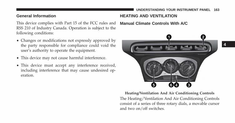
General Information
This device complies with Part 15 of the FCC rules andRSS 210 of Industry Canada. Operation is subject to thefollowing conditions:
• Changes or modifications not expressly approved bythe party responsible for compliance could void theuser’s authority to operate the equipment.
• This device may not cause harmful interference.
• This device must accept any interference received,including interference that may cause undesired op-eration.
HEATING AND VENTILATION
Manual Climate Controls With A/C
The Heating/Ventilation And Air Conditioning Controlsconsist of a series of three rotary dials, a movable cursorand two on/off switches.
Heating/Ventilation And Air Conditioning Controls
4
UNDERSTANDING YOUR INSTRUMENT PANEL 163
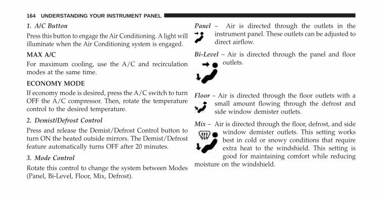
1. A/C Button
Press this button to engage the Air Conditioning. A light willilluminate when the Air Conditioning system is engaged.
MAX A/CFor maximum cooling, use the A/C and recirculationmodes at the same time.
ECONOMY MODEIf economy mode is desired, press the A/C switch to turnOFF the A/C compressor. Then, rotate the temperaturecontrol to the desired temperature.
2. Demist/Defrost Control
Press and release the Demist/Defrost Control button toturn ON the heated outside mirrors. The Demist/Defrostfeature automatically turns OFF after 20 minutes.
3. Mode Control
Rotate this control to change the system between Modes(Panel, Bi-Level, Floor, Mix, Defrost).
Panel – Air is directed through the outlets in theinstrument panel. These outlets can be adjusted todirect airflow.
Bi-Level – Air is directed through the panel and flooroutlets.
Floor – Air is directed through the floor outlets with asmall amount flowing through the defrost andside window demister outlets.
Mix – Air is directed through the floor, defrost, and sidewindow demister outlets. This setting worksbest in cold or snowy conditions that requireextra heat to the windshield. This setting isgood for maintaining comfort while reducing
moisture on the windshield.
164 UNDERSTANDING YOUR INSTRUMENT PANEL
4. Recirculation Control
Slide cursor to change the system between recirculationmode and outside air mode. Recirculation can be usedwhen outside conditions such as smoke, odors, dust, orhigh humidity are present.
NOTE:
• Continuous use of the Recirculation mode may makethe inside air stuffy and window fogging may occur.Extended use of this mode is not recommended.
• The use of the Recirculation mode in cold or dampweather could cause windows to fog on the inside,because of moisture buildup inside the vehicle. Se-lect the outside air position for maximum defogging.
5. Temperature Control
Rotate this control to regulate the temperature of the airinside the passenger compartment. Rotating the dial
counterclockwise into the blue area of the scale indicatescooler temperatures, while rotating clockwise into the redarea indicates warmer temperatures.
6. Blower Control
Rotate this control to regulate the amount of air forcedthrough the ventilation system in any mode. The blowerspeed increases as you move the control clockwise fromthe “0” (OFF) position. There are four blower speeds.
Heating
To heat the passenger compartment, proceed as follows:
1. Rotate the Temperature Control to the red section.
2. Turn the Blower Control to the desired speed.
3. Turn the Mode Control to .
4. Then operate the controls to maintain the desiredcomfort conditions.
4
UNDERSTANDING YOUR INSTRUMENT PANEL 165
NOTE:
• This air distribution allows the passenger compart-ment to be heated quickly.
• When the engine is cold, it takes a few minutes toachieve optimum passenger compartment heating.
Fast Demisting/Defrosting Of Windshield AndSide Windows
Proceed as follows:
1. Rotate the Temperature Control to the red section.
2. Turn the Blower Control to 4 (maximum fan speed).
3. Turn the Mode Control to .
4. Move the Recirculation Control to .
After demisting/defrosting, operate the controls as nor-mal to restore the required comfort conditions.
NOTE: The climate control system is very useful forspeeding up and maintaining demisting since it dehu-midifies the air. Adjust the controls as described previ-ously and switch on the climate control system bypressing the A/C button.
Window Demisting
In the event of considerable external moisture and/orrain and/or large differences in temperature inside andoutside the passenger compartment, perform the follow-ing preventive window demisting procedure:
1. Move the Recirculation Control to .
2. Rotate the Temperature Control to the red section.
3. Turn the Blower Control to 2 (intermediate fan speed).
4. Turn the Mode Control to with the possibility ofmoving it to position if window misting does notoccur.
166 UNDERSTANDING YOUR INSTRUMENT PANEL
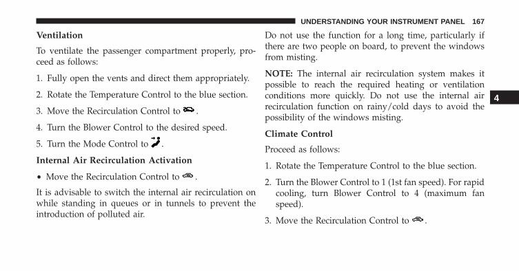
Ventilation
To ventilate the passenger compartment properly, pro-ceed as follows:
1. Fully open the vents and direct them appropriately.
2. Rotate the Temperature Control to the blue section.
3. Move the Recirculation Control to .
4. Turn the Blower Control to the desired speed.
5. Turn the Mode Control to .
Internal Air Recirculation Activation
• Move the Recirculation Control to .
It is advisable to switch the internal air recirculation onwhile standing in queues or in tunnels to prevent theintroduction of polluted air.
Do not use the function for a long time, particularly ifthere are two people on board, to prevent the windowsfrom misting.
NOTE: The internal air recirculation system makes itpossible to reach the required heating or ventilationconditions more quickly. Do not use the internal airrecirculation function on rainy/cold days to avoid thepossibility of the windows misting.
Climate Control
Proceed as follows:
1. Rotate the Temperature Control to the blue section.
2. Turn the Blower Control to 1 (1st fan speed). For rapidcooling, turn Blower Control to 4 (maximum fanspeed).
3. Move the Recirculation Control to .
4
UNDERSTANDING YOUR INSTRUMENT PANEL 167
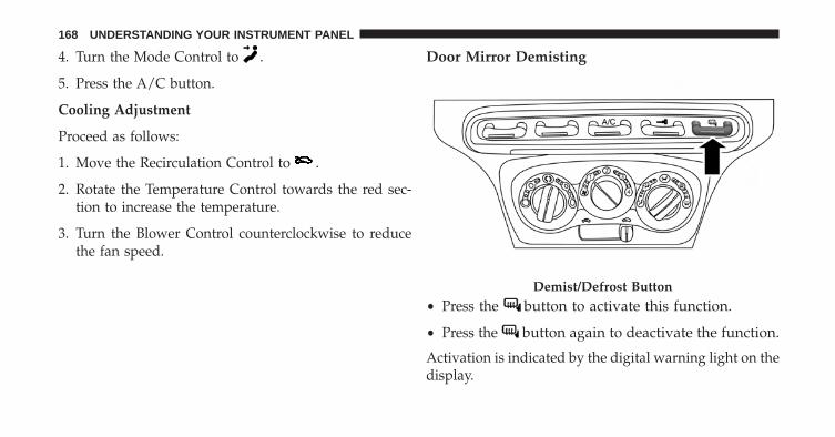
4. Turn the Mode Control to .
5. Press the A/C button.
Cooling Adjustment
Proceed as follows:
1. Move the Recirculation Control to .
2. Rotate the Temperature Control towards the red sec-tion to increase the temperature.
3. Turn the Blower Control counterclockwise to reducethe fan speed.
Door Mirror Demisting
• Press the button to activate this function.
• Press the button again to deactivate the function.
Activation is indicated by the digital warning light on thedisplay.
Demist/Defrost Button
168 UNDERSTANDING YOUR INSTRUMENT PANEL
System Maintenance
In winter, the climate control system must be turned on atleast once a month for about 10 minutes. Have the systeminspected at an authorized dealer before the summer.
NOTE: The system uses R-1234yf coolant which does notpollute the environment in the event of accidental leak-age. Under no circumstances should you use R-134a fluidwhich, in addition to being incompatible with the sys-tem’s components, contributes greatly to the greenhouseeffect.
4
UNDERSTANDING YOUR INSTRUMENT PANEL 169

STARTING AND OPERATING
CONTENTS� STARTING PROCEDURES . . . . . . . . . . . . . . . .174
▫ Automatic Transmission . . . . . . . . . . . . . . . .174
▫ Normal Starting. . . . . . . . . . . . . . . . . . . . . . .175
▫ Cold Weather Operation . . . . . . . . . . . . . . . .175
▫ If Engine Fails To Start . . . . . . . . . . . . . . . . .175
▫ After Starting . . . . . . . . . . . . . . . . . . . . . . . .176
▫ Turbo Charger “Cool Down” . . . . . . . . . . . . .176
� SIX-SPEED ALFA TWIN CLUTCHTRANSMISSION . . . . . . . . . . . . . . . . . . . . . . .176
▫ Using The Transmission . . . . . . . . . . . . . . . .177
� ALFA DNA SYSTEM(DYNAMIC VEHICLE CONTROL SYSTEM) . . .184
▫ Driving Modes . . . . . . . . . . . . . . . . . . . . . . .185
▫ System Failure. . . . . . . . . . . . . . . . . . . . . . . .189
▫ Launch Control . . . . . . . . . . . . . . . . . . . . . .189
� DRIVING ON SLIPPERY SURFACES . . . . . . . . .190
▫ Acceleration . . . . . . . . . . . . . . . . . . . . . . . . .190
▫ Traction . . . . . . . . . . . . . . . . . . . . . . . . . . . .190
� DRIVING THROUGH WATER . . . . . . . . . . . . .191
▫ Flowing/Rising Water . . . . . . . . . . . . . . . . . .191
5
▫ Shallow Standing Water . . . . . . . . . . . . . . . . .191
� PARKING BRAKE . . . . . . . . . . . . . . . . . . . . . .193
� BRAKE SYSTEM . . . . . . . . . . . . . . . . . . . . . . .195
� ESC (ELECTRONIC STABILITY CONTROL)SYSTEM . . . . . . . . . . . . . . . . . . . . . . . . . . . . .195
▫ System Activation . . . . . . . . . . . . . . . . . . . . .197
▫ System Intervention . . . . . . . . . . . . . . . . . . .197
▫ Electronic Brake Distribution System (EBD) . . .197
▫ Four-Wheel Anti-Lock Brake System (ABS) . . .197
▫ Cornering Brake Control System (CBC) . . . . . .199
▫ Drag Torque Control System (DTC) . . . . . . . .199
▫ AntiSlip Regulation System (ASR) . . . . . . . . .200
▫ Hill Start Assist (HSA) . . . . . . . . . . . . . . . . . .201
▫ Hydraulic Brake Assistant System (HBA) . . . .202
▫ Electronic Q2 System (E-Q2) . . . . . . . . . . . . .203
▫ Ready Alert Brake System (RAB) . . . . . . . . . .204
� TIRE SAFETY INFORMATION . . . . . . . . . . . . .204
▫ Tire Markings . . . . . . . . . . . . . . . . . . . . . . . .204
▫ Tire Identification Number (TIN). . . . . . . . . . .208
▫ Tire Terminology And Definitions . . . . . . . . . .210
▫ Tire Loading And Tire Pressure . . . . . . . . . . .211
� TIRES — GENERAL INFORMATION . . . . . . . .216
▫ Tire Pressure . . . . . . . . . . . . . . . . . . . . . . . .216
▫ Tire Inflation Pressures . . . . . . . . . . . . . . . . .218
▫ Tire Pressures For High Speed Operation . . . .219
▫ Radial Ply Tires . . . . . . . . . . . . . . . . . . . . . .219
172 STARTING AND OPERATING
▫ Tire Types . . . . . . . . . . . . . . . . . . . . . . . . . . .220
▫ Run Flat Tires — If Equipped . . . . . . . . . . . . .222
▫ Spare Tires — If Equipped . . . . . . . . . . . . . . .222
▫ Tire Spinning . . . . . . . . . . . . . . . . . . . . . . . .225
▫ Tread Wear Indicators . . . . . . . . . . . . . . . . . .225
▫ Life Of Tire . . . . . . . . . . . . . . . . . . . . . . . . .226
▫ Replacement Tires . . . . . . . . . . . . . . . . . . . . .227
� TIRE CHAINS (TRACTION DEVICES) . . . . . . .228
� TIRE ROTATION RECOMMENDATIONS . . . . .230
� TIRE PRESSURE MONITORING SYSTEM(TPMS) . . . . . . . . . . . . . . . . . . . . . . . . . . . . . .230
▫ Base System . . . . . . . . . . . . . . . . . . . . . . . . .233
▫ General Information . . . . . . . . . . . . . . . . . . .235
� FUEL REQUIREMENTS — 1750 Turbo . . . . . . .235
▫ Reformulated Gasoline . . . . . . . . . . . . . . . . .236
▫ Gasoline/Oxygenate Blends . . . . . . . . . . . . . .236
▫ E-85 Usage In Non-Flex Fuel Vehicles . . . . . . .237
▫ MMT In Gasoline . . . . . . . . . . . . . . . . . . . . .237
▫ Materials Added To Fuel . . . . . . . . . . . . . . . .238
▫ Fuel System Cautions. . . . . . . . . . . . . . . . . . .238
▫ Carbon Monoxide Warnings . . . . . . . . . . . . .239
� ADDING FUEL/SMART FUEL . . . . . . . . . . . . .240
� TRAILER TOWING . . . . . . . . . . . . . . . . . . . . .243
� RECREATIONAL TOWING(BEHIND MOTORHOME, ETC.) . . . . . . . . . . . .243
▫ Towing This Vehicle Behind Another Vehicle . .243
5
STARTING AND OPERATING 173
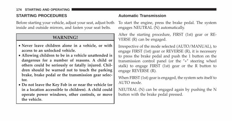
STARTING PROCEDURES
Before starting your vehicle, adjust your seat, adjust bothinside and outside mirrors, and fasten your seat belts.
WARNING!
• Never leave children alone in a vehicle, or withaccess to an unlocked vehicle.
• Allowing children to be in a vehicle unattended isdangerous for a number of reasons. A child orothers could be seriously or fatally injured. Chil-dren should be warned not to touch the parkingbrake, brake pedal or the transmission gear selec-tor.
• Do not leave the Key Fob in or near the vehicle (orin a location accessible to children). A child couldoperate power windows, other controls, or movethe vehicle.
Automatic Transmission
To start the engine, press the brake pedal. The systemengages NEUTRAL (N) automatically.
After the starting procedure, FIRST (1st) gear or RE-VERSE (R) can be engaged.
Irrespective of the mode selected (AUTO/MANUAL), toengage FIRST (1st) gear or REVERSE (R), it is necessaryto press the brake pedal and push the 1 button on thetransmission control panel (or the �+� steering wheelstalk) to engage FIRST (1st) gear or the R button toengage REVERSE (R).
When FIRST (1st) gear is engaged, the system sets itself toAUTO mode.
NEUTRAL (N) can be engaged again by pushing the Nbutton with the brake pedal pressed.
174 STARTING AND OPERATING
When the 1, N or R buttons are pushed (or �+� steeringwheel stalk is operated) without pressing the brakepedal, no gear change request is implemented by thesystem.
NOTE: REVERSE (R) cannot be engaged by pushing the�-� stalk on the steering wheel.
Normal Starting
NOTE: Normal starting of either a cold or a warmengine is obtained without pumping or pressing theaccelerator pedal.
Turn the ignition switch to the AVV/ACC (START)position and release it when the engine starts. If theengine fails to start within 10 seconds, turn the ignitionswitch to the STOP (OFF/LOCK) position, wait 10 to 15seconds, then repeat the “Normal Starting” procedure.
Cold Weather Operation
Your engine is designed to operate at temperatures aslow as 0°F (-18°C).
CAUTION!
Use of the recommended SAE 5W-40 Synthetic oiland adhering to the prescribed oil change intervals isimportant to prevent engine damage and ensuresatisfactory starting in cold conditions.
If Engine Fails To Start
WARNING!
Never pour fuel or other flammable liquids into thethrottle body air inlet opening in an attempt to startthe vehicle. This could result in a flash fire causingserious personal injury.
5
STARTING AND OPERATING 175
CAUTION!
• Do not attempt to push or tow your vehicle to get itstarted. Vehicles equipped with a Alfa Twin ClutchTransmission cannot be started this way. Unburnedfuel could enter the catalytic converter and once theengine has started, ignite and damage the converterand vehicle.
• To prevent damage to the starter, do not continu-ously crank the engine for more than 15 seconds ata time. Wait 10 to 15 seconds before trying again.
After Starting
The idle speed is controlled automatically and it willdecrease as the engine warms up.
Turbo Charger “Cool Down”
This vehicle is equipped with an after-run pump to coolthe turbocharger after the engine is shut off. Depending
on the type of driving and the amount of cargo, the pumpwill run for up to five minutes after the engine has beenshut off to circulate coolant through the turbocharger.
Although the pump is rubber-mounted for quiet opera-tion, it is normal to hear it running during this time.
SIX-SPEED ALFA TWIN CLUTCH TRANSMISSION
WARNING!
• It is dangerous to shift out of NEUTRAL if theengine speed is higher than idle speed. If your footis not firmly pressing the brake pedal, the vehiclecould accelerate quickly forward or in reverse. Youcould lose control of the vehicle and hit someone orsomething. Only shift into gear when the engine isidling normally and your foot is firmly pressingthe brake pedal.
(Continued)
176 STARTING AND OPERATING
WARNING! (Continued)• Unintended movement of a vehicle could injure
those in or near the vehicle. As with all vehicles,you should never exit a vehicle while the engine isrunning.
• Before exiting a vehicle, always shift the vehicleinto FIRST gear or REVERSE, apply the parkingbrake, turn the vehicle OFF, remove the key fobfrom the ignition and lock your vehicle.
• Never leave children alone in a vehicle, or withaccess to an unlocked vehicle. Allowing children tobe in a vehicle unattended is dangerous for anumber of reasons. A child or others could beseriously or fatally injured. Children should bewarned not to touch the parking brake, brake pedalor the transmission gear selector.
(Continued)
WARNING! (Continued)• Do not leave the ignition key in or near the vehicle
(or in a location accessible to children). A childcould operate power windows, other controls, ormove the vehicle.
Using The Transmission
This vehicle is equipped with a Six-Speed Alfa TwinClutch transmission with steering wheel mounted shiftpaddles.
When the ignition is in the OFF position, the transmissioncontrols (shift paddles on the steering wheel, and gearselector buttons on the center console) are disabled.
5
STARTING AND OPERATING 177
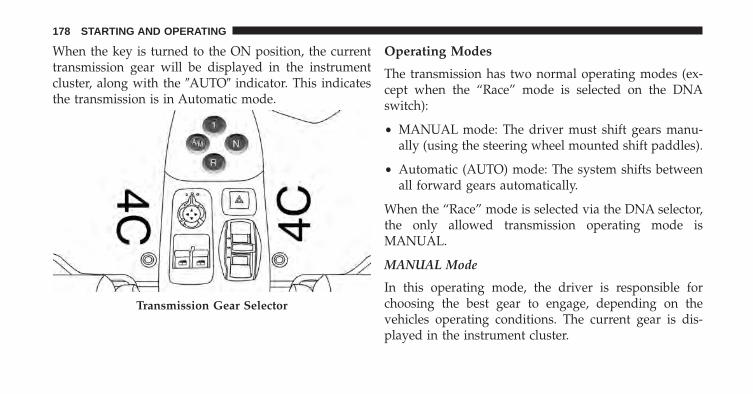
When the key is turned to the ON position, the currenttransmission gear will be displayed in the instrumentcluster, along with the �AUTO� indicator. This indicatesthe transmission is in Automatic mode.
Operating Modes
The transmission has two normal operating modes (ex-cept when the “Race” mode is selected on the DNAswitch):
• MANUAL mode: The driver must shift gears manu-ally (using the steering wheel mounted shift paddles).
• Automatic (AUTO) mode: The system shifts betweenall forward gears automatically.
When the “Race” mode is selected via the DNA selector,the only allowed transmission operating mode isMANUAL.
MANUAL Mode
In this operating mode, the driver is responsible forchoosing the best gear to engage, depending on thevehicles operating conditions. The current gear is dis-played in the instrument cluster.
Transmission Gear Selector
178 STARTING AND OPERATING
To activate/deactivate MANUAL mode, push the A/Mbutton on the center console when the transmission is inany forward gear.
Use the “+” shift paddle to engage a higher gear, or the“–” paddle to engage a lower gear.
If a requested gear shift is not allowed (typically, becauseit would cause engine overspeed or lugging), an acousticsignal will sound and the transmission will remain in theexisting gear.
The transmission will automatically downshift duringclosed-throttle decelerations, to prevent engine lugging.When coming to a stop, the transmission will automati-cally select FIRST (1st) gear. The driver must manuallyupshift the transmission (by tapping the + shift paddle)as the vehicle accelerates.
NOTE: To provide better comfort, the transmission willup-shift to the next available gear if the engine speedlimit is reached. This feature is only available in NATU-RAL and ALL WEATHER Modes.
AUTO Mode
In AUTO mode the transmission shifts gears automati-cally depending on vehicle speed, engine RPM, andaccelerator pedal position.
AUTO is the default operating mode at startup. When inAUTO mode, �AUTO� appears in the instrument cluster,adjacent to the current gear display.
To toggle between AUTO and MANUAL modes, pushthe A/M button on the center console.
5
STARTING AND OPERATING 179
Accelerating From A Stop
FIRST (1st) and REVERSE (R) can only be engaged (at astop) by pushing “1” or “R” when the brake pedal ispressed.
To drive, press the brake pedal, and select 1 (1st) or R(REVERSE) by pushing “1” or “R” using the transmissiongear selector buttons on the center console. Then releasethe brake pedal and smoothly press the accelerator pedal.
NOTE:
• The vehicle will not “creep” when the brake pedal isreleased, and may in fact roll down on an incline.Leaving from a stop, the accelerator pedal must bepressed to transmit driving torque to the wheels.
• When starting on a fairly steep incline, it may behelpful to engage the parking brake.
• The vehicle can only be launched (from a stop) inFIRST (1st) or REVERSE (R). SECOND (2nd) gear (orhigher) cannot be engaged when the vehicle is station-ary.
• If the brake pedal is not depressed (and the vehicle isstationary for a period of time), the transmission willautomatically engage NEUTRAL (N).
• FIRST (1st) and REVERSE (R) gears can only beengaged at vehicle speeds below 2 mph (3 km/h). Atspeeds below 6 mph (10 km/h), attempts to shift from1st to R (or R to 1st) will only be allowed if the vehiclespeed drops below the 2 mph (3 km/h) thresholdwithin three seconds of the request; otherwise, thetransmission will shift to NEUTRAL (N). The drivershould then repeat the request for 1st or R once thevehicle has come to a stop.
180 STARTING AND OPERATING
Shift Paddles
In MANUAL mode, the steering wheel mounted shiftpaddles (labeled + and -) control the transmission shift-ing.
Tapping the (+) paddle will upshift the transmission tothe next higher gear, while tapping the (-) paddle willdownshift to the next lower gear. The current gear isdisplayed in the instrument cluster. If a requested shiftwould cause engine lugging or overspeed, that requestwill be ignored.
In AUTO mode, tapping a shift paddle will temporarilyplace the transmission in MANUAL mode, and executethe requested upshift or downshift (if allowable). Thetransmission will then return to AUTO mode after a briefinterval.
Pressing a shift paddle will only shift the transmissionone gear at a time. Holding a paddle depressed will not
command multiple shifts; the paddle must be pressedmultiple times in succession to generate multiple shifts.
Neutral (N)
Use this range when the vehicle is standing for prolongedperiods with the engine running. Always apply theparking brake if you must leave the vehicle.
At engine startup, the transmission will automaticallyselect NEUTRAL (N) and AUTO mode. The brake pedalmust be pressed when starting the engine.
To select NEUTRAL (N) when the vehicle is stationary,turn the ignition key to the MAR-ON position (enginerunning or not), press the brake pedal, and push the Nbutton on the transmission gear selector.
When the vehicle is moving (with ignition ON), pushingthe NEUTRAL (N) button will engage N, regardless ofwhether the brake pedal is pressed.
5
STARTING AND OPERATING 181
WARNING!
Do not coast in NEUTRAL and never turn off theignition to coast down a hill. Coasting in NEUTRALand turning off the ignition while coasting severelylimit your ability to respond to changing traffic orroad conditions. Failure to follow this WARNINGmay result in your loss of vehicle control, collisionand serious injury or death.
With the vehicle in motion, to engage a gear from theNEUTRAL (N) position, push the 1 button on the trans-mission control panel (it is not necessary to press thebrake pedal). The transmission will engage the correctgear according to the vehicles speed.
Acoustic Signal
If the vehicle is stationary with the engine running andFIRST (1st) gear or REVERSE (R) engaged, the systemactivates an acoustic signal and automatically places thetransmission in NEUTRAL (N) when:
• The accelerator and/or brake pedal are not operatedfor at least three minutes.
• The brake pedal is pressed for longer than 10 minutes.
• The driver’s door is opened and the accelerator pedalor the brake pedal are not operated for at least one anda half seconds.
• A fault has been detected in the transmission.
Parking The Vehicle
When parking and leaving the vehicle, proceed as follows:
1. Make sure that the vehicle has come to a complete stop.
182 STARTING AND OPERATING
2. With the brake pedal depressed, put the vehicle intoeither a forward or reverse gear by pressing 1 or R.(The vehicle may already be in 1 or R if you were justdriving.)
3. Engage the parking brake.
4. Turn off and remove the key.
5. Release the brake.
When parking on an incline, turn the front wheels towardthe curb on a downhill slope and away from the curb onan uphill slope. Always chock the wheels when parkingon steep grades.
General Notes
When the vehicle is stopped and in gear, always keep thebrake pedal pressed until you decide to set off, thenrelease the brake and accelerate gradually.
During prolonged stops with the engine running, it isadvisable to keep the transmission in NEUTRAL (N).
When stopped on an incline, always hold the vehicle inplace using the brakes. On steep inclines, Hill Start Assist(HSA) will temporarily hold the vehicle in position whenthe brake pedal is released. If the accelerator pedal is notapplied after a short time, the vehicle will roll back.Either reapply the brake (to hold the vehicle) or press theaccelerator to climb the hill.
Only shift between FIRST (1st) and REVERSE (R) whencompletely stopped, with the brake pedal pressed.
When necessary, it is possible to engage FIRST (1st),REVERSE (R) or NEUTRAL (N) with the engine off, thekey at MAR-ON and the brake pressed. In this case, waitat least five seconds between one gear change and thenext, in order to safeguard the operation of the hydraulicsystem, and the pump in particular.
5
STARTING AND OPERATING 183
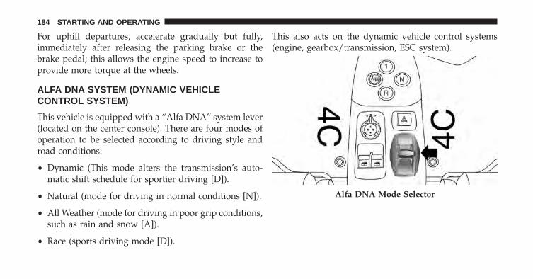
For uphill departures, accelerate gradually but fully,immediately after releasing the parking brake or thebrake pedal; this allows the engine speed to increase toprovide more torque at the wheels.
ALFA DNA SYSTEM (DYNAMIC VEHICLECONTROL SYSTEM)
This vehicle is equipped with a “Alfa DNA” system lever(located on the center console). There are four modes ofoperation to be selected according to driving style androad conditions:
• Dynamic (This mode alters the transmission’s auto-matic shift schedule for sportier driving [D]).
• Natural (mode for driving in normal conditions [N]).
• All Weather (mode for driving in poor grip conditions,such as rain and snow [A]).
• Race (sports driving mode [D]).
This also acts on the dynamic vehicle control systems(engine, gearbox/transmission, ESC system).
Alfa DNA Mode Selector
184 STARTING AND OPERATING
Driving Modes
The Alfa DNA system lever will always return to thecenter position after use.
The selected driving mode is indicated by the corre-sponding LED switching in the panel and by an indica-tion on the display.
Dynamic Mode
Activation
Move the Alfa DNA system lever upwards (to the letter“D”) and hold in this position for half a second, until thecorresponding LED lights up and the Dynamic modeactivation indicator appears on the display.
When Dynamic mode is activated, the turbochargerpressure and engine oil temperature screen is displayedautomatically. When released, the Alfa DNA system leverwill return to the central position.
NOTE: Dynamic Mode will be inhibited until the vehiclehas accumulated 155 miles (250 km).
Electronic Stability Control (ESC) and Anti-Slip Regu-lation (ASR) systems:
The ESC and ASR system ensures more enjoyable,sportier driving while guaranteeing the stability of thevehicle.
Electronic Q2 system:
The system increases vehicle stability while acceleratingon bends, improving the agility of the vehicle.
Engine And Gearbox/Transmission:
The system adjusts the transmission shift calibration forsportier shifting.
NOTE: In Dynamic mode, the engine response to theaccelerator pedal position increases considerably. Conse-quently, driving is less fluid and comfortable.
5
STARTING AND OPERATING 185
Deactivation
To deactivate Dynamic mode and return to Natural,move lever downwards (to letter “A”) and keep it in thisposition for half a second.
The LED corresponding to Natural mode will light upand the Natural mode activation indication will appearon the display.
Race Mode
Activation
Starting in Dynamic mode, move the Alfa DNA systemlever upwards (to the letter “D”) and hold in this positionfor five seconds, until the Race mode activation indicatorappears on the display.
When Race mode is activated, the longitudinal/lateralaccelerometer indicator screen (G-meter information) isdisplayed automatically. This considers gravitational ac-celeration (G).
Electronic Stability Control (ESC) and Anti-Slip Regu-lation (ASR) systems:
These systems are deactivated in order to ensure thefullest sensation of sport, leaving the driver in full controlof the vehicle. When the vehicle is in unstable conditions,the ESC reactivates automatically when the brake pedalis pressed until the ABS intervenes, thus returning thevehicle to stable conditions. To deactivate the ESC andASR systems reactivate Race mode.
Electronic Q2 system:
The system increases vehicle stability while acceleratingon bends, improving the agility of the vehicle.
186 STARTING AND OPERATING
Engine And Gearbox/Transmission:
The system adjusts the transmission shift calibration forsportier shifting.
NOTE: In Race mode, the sensitivity of the acceleratorpedal increases considerably. Consequently, driving isless fluid and comfortable.
In Race mode the transmission only works in MANUALmode. Refer to the �Manual Operation� in �Starting andOperating� for further information.
Deactivation
To deactivate Race mode and return to Dynamic mode,move the Alfa DNA system lever downwards (to letter“A”) and keep it in this position for half a second.
The LED corresponding to Dynamic mode will light upand the Dynamic mode activation indication will appearon the display.
Natural Mode
Electronic Stability Control (ESC) and Anti-Slip Regu-lation (ASR) systems:
ESC and ASR system thresholds are aimed at providingcomfort and safety in normal grip and driving condi-tions.
Electronic Q2 system:
The system is calibrated to ensure the best drivingcomfort.
Engine And Gearbox/Transmission:
Standard response shifting.
5
STARTING AND OPERATING 187
All Weather Mode
Activation
Move the Alfa DNA system lever downwards (to theletter “A”) and hold in this position for half a second,until the corresponding LED lights up and the AllWeather mode activation indicator appears on the dis-play.
Electronic Stability Control (ESC) and Anti-Slip Regu-lation (ASR) systems:
ESC and ASR system thresholds are aimed at ensuringmaximum safety in low-grip driving conditions. It isadvisable to select All Weather mode in the presence oflow-grip road surfaces.
Electronic Q2 System:
The system is deactivated.
Engine And Gearbox/Transmission:
Standard response shifting.
Deactivation
To deactivate All Weather mode and return to Naturalmode, move the Alfa DNA system lever upwards (toletter “D”) and keep it in this position for half a second.
NOTE:
• When the engine is next started, All weather mode orNatural mode will be retained when the vehicle isrestarted.
• When the engine is next started, Race mode or Dy-namic mode previously selected is not retained. Thesystem will reactivate in Natural mode.
• It is not possible to go directly from Dynamic mode toAll Weather mode and vice versa. You must always firstgo back to Natural mode and then select the other mode.
188 STARTING AND OPERATING
System Failure
In the event of system failure or a fault with the gearselector, no driving modes can be selected.
The display will become grey (same screen as �Natural�mode) but without an indication of the Alfa DNA setting.The display will also show a warning message.
Please contact your authorized dealer for service.
Launch Control
The Launch Control strategy permits high-performanceacceleration from stand still.
This strategy can be activated with vehicle at a standstill,Race mode selected and FIRST (1st) gear engaged.
The sequence of operations to perform is as follows:
1. Press the brake pedal and hold it down.
2. Press the accelerator pedal and hold it down.
3. Press the �–� paddle behind the steering wheel. (Thisallows the engine to rev above the 3000 RPM limit.)
When the brake pedal is released, the vehicle will startwith maximum acceleration. Despite the MANUALmode, the vehicle will automatically shift the gear toguarantee maximum acceleration, once the correct shift-ing speed has been reached.
WARNING!
Launch Control is intended for off-highway or off-road use only and should not be used on any publicroadways. Use Launch Control only in a controlledand dry track environment; within the limits of thelaw. Actual Launch Control performance may changedepending on the surface and current traction condi-tions. The capabilities of the vehicle as measured bythe performance pages must never be exploited in a
(Continued)
5
STARTING AND OPERATING 189
WARNING! (Continued)reckless or dangerous manner, which can jeopardizethe user’s safety or the safety of others. Only a safe,attentive, and skillful driver can prevent accidents.Failure to follow this warning may result in seriousinjury or death.
To discontinue the strategy, simply interrupt the abovesequence of operations or release the accelerator pedal.
DRIVING ON SLIPPERY SURFACES
Acceleration
Rapid acceleration on snow covered, wet, or other slip-pery surfaces may cause the driving wheels to pullerratically to the right or left. This phenomenon occurswhen there is a difference in the surface traction underthe rear (driving) wheels.
WARNING!
Rapid acceleration on slippery surfaces is dangerous.Unequal traction can cause sudden pulling of the rearwheels. You could lose control of the vehicle andpossibly have a collision. Accelerate slowly andcarefully whenever there is likely to be poor traction(ice, snow, wet mud, loose sand, etc.).
Traction
When driving on wet or slushy roads, it is possible for awedge of water to build up between the tire and roadsurface. This is known as hydroplaning and may causepartial or complete loss of vehicle control and stoppingability. To reduce this possibility, the following precau-tions should be observed:
• Slow down during rainstorms or when the roads areslushy.
190 STARTING AND OPERATING
• Slow down if the road has standing water or puddles.
• Replace tires when tread wear indicators first becomevisible.
• Keep tires properly inflated.
• Maintain sufficient distance between your vehicle andthe vehicle in front of you to avoid a collision in asudden stop.
Your vehicle may be equipped with a Limited SlipDifferential (LSD) that reduces, but does not eliminate,the amount of wheel slip across a given axle for im-proved handling.
DRIVING THROUGH WATER
Driving through water more than a few inches/centimeters deep will require extra caution to ensuresafety and prevent damage to your vehicle.
Flowing/Rising Water
WARNING!
Do not drive on or across a road or path where wateris flowing and/or rising (as in storm run-off). Flow-ing water can wear away the road or path’s surfaceand cause your vehicle to sink into deeper water.Furthermore, flowing and/or rising water can carryyour vehicle away swiftly. Failure to follow thiswarning may result in injuries that are serious orfatal to you, your passengers, and others around you.
Shallow Standing Water
Although your vehicle is capable of driving throughshallow standing water, consider the following Cautionsand Warnings before doing so.
5
STARTING AND OPERATING 191
WARNING!
• Driving through standing water limits your vehi-cle’s traction capabilities. Do not exceed 5 mph(8 km/h) when driving through standing water.
• Driving through standing water limits your vehi-cle’s braking capabilities, which increases stoppingdistances. Therefore, after driving through stand-ing water, drive slowly and lightly press on thebrake pedal several times to dry the brakes.
• Failure to follow these warnings may result ininjuries that are serious or fatal to you, your pas-sengers, and others around you.
CAUTION!
• Always check the depth of the standing waterbefore driving through it. Never drive through
(Continued)
CAUTION! (Continued)standing water that is deeper than the bottom ofthe tire rims mounted on the vehicle.
• Determine the condition of the road or the paththat is under water and if there are any obstacles inthe way before driving through the standing water.
• Do not exceed 5 mph (8 km/h) when driving throughstanding water. This will minimize wave effects.
• Driving through standing water may cause damageto your vehicle’s drivetrain components. Always in-spect your vehicle’s fluids (i.e., engine oil, transmis-sion, axle, etc.) for signs of contamination (i.e., fluidthat is milky or foamy in appearance) after drivingthrough standing water. Do not continue to operatethe vehicle if any fluid appears contaminated, as thismay result in further damage. Such damage is notcovered by the New Vehicle Limited Warranty.
(Continued)
192 STARTING AND OPERATING
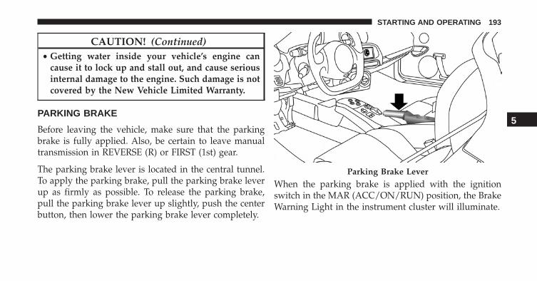
CAUTION! (Continued)• Getting water inside your vehicle’s engine can
cause it to lock up and stall out, and cause seriousinternal damage to the engine. Such damage is notcovered by the New Vehicle Limited Warranty.
PARKING BRAKE
Before leaving the vehicle, make sure that the parkingbrake is fully applied. Also, be certain to leave manualtransmission in REVERSE (R) or FIRST (1st) gear.
The parking brake lever is located in the central tunnel.To apply the parking brake, pull the parking brake leverup as firmly as possible. To release the parking brake,pull the parking brake lever up slightly, push the centerbutton, then lower the parking brake lever completely.
When the parking brake is applied with the ignitionswitch in the MAR (ACC/ON/RUN) position, the BrakeWarning Light in the instrument cluster will illuminate.
Parking Brake Lever
5
STARTING AND OPERATING 193
When parking on a hill, it is important to turn the frontwheels toward the curb on a downhill grade and awayfrom the curb on an uphill grade. The parking brake shouldalways be applied whenever the driver is not in the vehicle.
WARNING!
• Never leave children alone in a vehicle, or withaccess to an unlocked vehicle.
• Allowing children to be in a vehicle unattended isdangerous for a number of reasons. A child or otherscould be seriously or fatally injured. Children shouldbe warned not to touch the parking brake, brake pedalor the transmission gear selector.
• Do not leave the Key Fob in or near the vehicle orin a location accessible to children. A child couldoperate power windows, other controls, or movethe vehicle.
(Continued)
WARNING! (Continued)• Be sure the parking brake is fully disengaged
before driving; failure to do so can lead to brakefailure and a collision.
• Always fully apply the parking brake when leav-ing your vehicle, or it may roll and cause damage orinjury. Also be certain to leave a manual transmis-sion in REVERSE or FIRST gear. Failure to do somay allow the vehicle to roll and cause damage orinjury.
CAUTION!
If the Brake Warning Light remains on with theparking brake released, a brake system malfunctionis indicated. Have the brake system serviced by anauthorized dealer immediately.
194 STARTING AND OPERATING
BRAKE SYSTEM
Your vehicle is equipped with dual hydraulic brakesystems. If either of the two hydraulic systems losesnormal capability, the remaining system will still func-tion. However, there will be some loss of overall brakingeffectiveness. You may notice increased pedal travelduring application, greater pedal force required to slowor stop, and potential activation of the “Brake SystemWarning Light”.
In the event power assist is lost for any reason (i.e.,repeated brake applications with the engine off), thebrakes will still function. However, the effort required tobrake the vehicle will be much greater than that requiredwith the power system operating.
ESC (ELECTRONIC STABILITY CONTROL)SYSTEM
The ESC system improves the directional control andstability of the vehicle in various driving conditions.
The ESC system corrects the vehicle understeer andoversteer, distributing the brake force on the appropriatewheels. The torque supplied by the engine can also bereduced in order to maintain control of the vehicle.
WARNING!
• Electronic Stability Control (ESC) cannot preventthe natural laws of physics from acting on thevehicle, nor can it increase the traction afforded byprevailing road conditions. ESC cannot prevent allcollisions, including those resulting from excessivespeed in turns, driving on very slippery surfaces, or
(Continued)
5
STARTING AND OPERATING 195
WARNING! (Continued)hydroplaning. ESC also cannot prevent collisionsresulting from loss of vehicle control due to inap-propriate driver input for the conditions. Only asafe, attentive, and skillful driver can prevent col-lisions.The capabilities of an ESC equipped ve-hicle must never be exploited in a reckless ordangerous manner which could jeopardize the us-er’s safety or the safety of others.
• Vehicle modifications, or failure to properly main-tain your vehicle, may change the handling charac-teristics of your vehicle, and may negatively affectthe performance of the ESC system. Changes to thesteering system, suspension, braking system, tiretype and size or wheel size may adversely affect ESCperformance. Improperly inflated and unevenlyworn tires may also degrade ESC performance. Any
(Continued)
WARNING! (Continued)vehicle modification or poor vehicle maintenancethat reduces the effectiveness of the ESC system canincrease the risk of loss of vehicle control, vehiclerollover, personal injury and death.
The ESC system uses sensors installed on the vehicle todetermine the trajectory that the driver intends to followand compares it with the vehicles effective trajectory.When the real trajectory deviates from the desired trajec-tory, the ESC system intervenes to counter the vehiclesundersteer or oversteer.
• Oversteer: occurs when the vehicle is turning morethan it should according to the angle of the steeringwheel.
• Understeer: occurs when the vehicle is turning lessthan it should according to the angle of the steeringwheel.
196 STARTING AND OPERATING
This vehicle’s advanced electronic brake control systemalso includes: Electronic Brake Distribution (EBD), Anti-Lock Brake System (ABS), Cornering Brake Control Sys-tem (CBC), Drag Torque Control System (DTC), AntiSlipRegulation System (ASR), Hill Start Assist (HSA), Hy-draulic Brake Assistant System (HBA), ELECTRONIC Q2system (E-Q2) and Ready Alert Brake (RAB). All of thesystems work together to enhance vehicle stability andcontrol in various driving conditions, and are commonlyreferred to as ESC.
System Activation
The ESC system activates automatically when the engineis started and can only be deactivated by selecting �Race�mode. Refer to the �Six-Speed Alfa Twin Clutch Trans-mission� in this section for further information.
System Intervention
This is indicated by the flashing of the warning light onthe instrument panel, to inform the driver that the vehicleis in critical stability and grip conditions.
Electronic Brake Distribution System (EBD)
The EBD system is an integral part of the ESC system andintervenes during braking, distributing the brake forceoptimally between front and rear wheels.
This guarantees greater braking stability for the vehicle,preventing sudden locking of the rear wheels and theconsequent instability of the vehicle.
Four-Wheel Anti-Lock Brake System (ABS)
The Four-Wheel ABS is designed to aid the driver inmaintaining vehicle control under adverse braking con-ditions. The system operates with a separate computer tomodulate hydraulic pressure, to prevent wheel lock-upand to help avoid skidding on slippery surfaces.
5
STARTING AND OPERATING 197
The system’s pump motor runs during an ABS stop toprovide regulated hydraulic pressure. The pump motormakes a low humming noise during operation, which isnormal.
The ABS includes an amber ABS Warning Light. Whenthe light is illuminated, the ABS is not functioning. Thesystem reverts to standard non-anti-lock brakes. Turningthe ignition Off and On again may reset the ABS if thefault detected was only momentary.
WARNING!
• When the ABS intervenes and you feel the brakepedal pulsating, do not reduce the pressure, buthold it down firmly and confidently; in doing soyou will brake in the shortest distance possible,depending on the current road conditions.
(Continued)
WARNING! (Continued)• For maximum efficiency of the braking system, a
bedding-in period of about 311 miles (500 km) isrequired: during this period it is advisable to avoidsharp, repeated and prolonged braking.
• If the ABS intervenes, this indicates that the grip ofthe tires on the road is nearing its limit: you mustslow down to a speed compatible with the avail-able grip.
• The ABS can’t overrule the natural laws of physics,and can’t increase the grip available according tothe condition of the road.
• The ABS cannot prevent accidents, including thosedue to excessive speed on corners, driving onlow-grip surfaces or aquaplaning.
(Continued)
198 STARTING AND OPERATING
WARNING! (Continued)• The capability of the ABS must never be tested
irresponsibly and dangerously, in such a way as tocompromise personal safety and the safety of oth-ers.
• For the correct operation of the ABS, the tires mustof necessity be the same make and type on allwheels, in perfect condition and, above all, of theprescribed type and dimensions.
When you are in a severe braking condition involving theuse of the ABS, you will experience some pedal drop asthe vehicle comes to a stop. This is the result of thesystem reverting to the base brake system.
Engagement of the ABS may be accompanied by apulsing sensation. You may also hear a clicking noise.These occurrences are normal and indicate that thesystem is functioning properly.
System Intervention
A slight pulsing of the brake pedal and noise indicatesthe intervention of the ABS: this is completely normalwhen the system intervenes.
Cornering Brake Control System (CBC)
The system acts when braking on corners, optimizing thedistribution of brake pressure on the four wheels: thesystem prevents the wheels on the inside of the corner(less affected by the weight of the vehicle) from locking,ensuring better stability and direction for the vehicle.
Drag Torque Control System (DTC)
This is an integral part of the ESC system and intervenesin the event of sudden downshifting, or during brakingwhen the ABS intervenes, restoring torque to the engineand thus preventing excessive drag at the drive wheels,which may lead the wheels to lock and a loss of vehiclestability, above all in low-grip conditions.
5
STARTING AND OPERATING 199
AntiSlip Regulation System (ASR)
WARNING!
• Electronic Stability Control (ESC) cannot preventthe natural laws of physics from acting on thevehicle, nor can it increase the traction afforded byprevailing road conditions. ESC cannot prevent allcollisions, including those resulting from excessivespeed in turns, driving on very slippery surfaces, orhydroplaning. ESC also cannot prevent collisionsresulting from loss of vehicle control due to inap-propriate driver input for the conditions. Only asafe, attentive, and skillful driver can prevent col-lisions.The capabilities of an ESC equipped ve-hicle must never be exploited in a reckless ordangerous manner which could jeopardize the us-er’s safety or the safety of others.
(Continued)
WARNING! (Continued)• Vehicle modifications, or failure to properly main-
tain your vehicle, may change the handling charac-teristics of your vehicle, and may negatively affectthe performance of the ESC system. Changes to thesteering system, suspension, braking system, tiretype and size or wheel size may adversely affect ESCperformance. Improperly inflated and unevenlyworn tires may also degrade ESC performance. Anyvehicle modification or poor vehicle maintenancethat reduces the effectiveness of the ESC system canincrease the risk of loss of vehicle control, vehiclerollover, personal injury and death.
This is an integral part of the ESC system and automati-cally operates in the event of one or both drive wheelsslipping, loss of grip on wet roads (hydroplaning) andacceleration on slippery, snowy or icy roads, etc.
200 STARTING AND OPERATING
Depending on the slipping conditions, two differentcontrol systems are activated:
• If the slipping involves both drive wheels, the ASRsystem intervenes, reducing the power transmitted bythe engine.
• If the slipping only involves one of the drive wheels, italso intervenes automatically, braking the wheel that isslipping.
System Intervention
This is indicated by the flashing of the warning light onthe instrument panel, to inform the driver that the vehicleis in critical stability and grip conditions.
Hill Start Assist (HSA)
This is an integral part of the ESC system and facilitatesstarting on slopes, activating automatically in the follow-ing cases:
• Uphill: vehicle stationary on a road with a gradienthigher than 5%, engine running, brake pressed andtransmission in neutral (N) or gear other than reverseengaged.
• Downhill: vehicle stationary on a road with a gradienthigher than 5%, engine running, brake pressed andreverse (R) gear engaged.
When setting off, the ESC system control unit maintainsthe braking pressure on the wheels until the enginetorque necessary for starting is reached, or in any case fora maximum of two seconds, allowing your right foot tobe moved easily from the brake pedal to the accelerator.
5
STARTING AND OPERATING 201
When the two seconds have elapsed, without starting,the system is automatically deactivated, gradually releas-ing the braking pressure. During this release stage, thetypical brake disengagement noise, indicating that thevehicle is going to move imminently, can be heard.
NOTE:
• HSA is not a parking brake; therefore, never leave thevehicle without having engaged the parking brake,turned the engine off and engaged first gear, so thatthe vehicle is parked in safe conditions.
• There may be situations on small gradients (less than8%), with vehicle laden, in which the Hill Holdersystem may not activate, causing a slight reversingmotion and increasing the risk of collision with an-other vehicle or object. The driver is, in any case,responsible for safe driving.
Hydraulic Brake Assistant System (HBA)
WARNING!
• The HBA system can’t overrule the natural laws ofphysics, and can’t increase the grip available ac-cording to the condition of the road.
• The HBA system cannot prevent accidents, includ-ing those due to excessive speed on corners, driv-ing on low-grip surfaces or aquaplaning.
• The capability of the HBA system must never betested irresponsibly and dangerously, in such away as to compromise the safety of the driver, theother occupants of the vehicle or any other roaduser.
202 STARTING AND OPERATING
The HBA system is designed to improve the vehiclesbraking capacity during emergency braking. The systemdetects emergency braking by monitoring the speed andforce with which the brake pedal is pressed, and conse-quently applies the optimal brake pressure. This canreduce the braking distance, the HBA system thereforecompletes the ABS.
Maximum assistance from the HBA system is obtainedpressing the brake pedal very quickly. In addition, thebrake pedal should be pressed continuously duringbraking, avoiding intermittent presses, to get the mostout of the system.
Do not reduce pressure on the brake pedal until brakingis no longer necessary.
The HBA system is deactivated when the brake pedal isreleased.
Electronic Q2 System (E-Q2)
The �Electronic Q2� system intervenes during accelera-tion on corners, braking the inner drive wheel and thusincreasing the traction of the outer wheel (which bearsmore of the vehicles weight): the torque is thus distrib-uted optimally between the drive wheels in accordancewith the driving conditions and road surface, permittingparticularly effective, sporty driving. 5
STARTING AND OPERATING 203
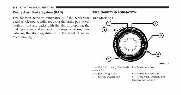
Ready Alert Brake System (RAB)
This function activates automatically if the acceleratorpedal is released rapidly, reducing the brake pad travel(both at front and back), with the aim of preparing thebraking system and enhancing its responsiveness, thusreducing the stopping distance in the event of subse-quent braking.
TIRE SAFETY INFORMATION
Tire Markings
1 — U.S. DOT Safety StandardsCode (TIN)
4 — Maximum Load
2 — Size Designation 5 — Maximum Pressure3 — Service Description 6 — Treadwear, Traction and
Temperature Grades
204 STARTING AND OPERATING
NOTE:
• P (Passenger) — Metric tire sizing is based on U.S.design standards. P-Metric tires have the letter “P”molded into the sidewall preceding the size designa-tion. Example: P215/65R15 95H.
• European — Metric tire sizing is based on Europeandesign standards. Tires designed to this standard havethe tire size molded into the sidewall beginning withthe section width. The letter �P� is absent from this tiresize designation. Example: 215/65R15 96H.
• LT (Light Truck) — Metric tire sizing is based on U.S.design standards. The size designation for LT-Metrictires is the same as for P-Metric tires except for theletters “LT” that are molded into the sidewall preced-ing the size designation. Example: LT235/85R16.
• Temporary spare tires are designed for temporaryemergency use only. Temporary high pressure com-pact spare tires have the letter “T” or “S” molded intothe sidewall preceding the size designation. Example:T145/80D18 103M.
• High flotation tire sizing is based on U.S. designstandards and it begins with the tire diameter moldedinto the sidewall. Example: 31x10.5 R15 LT.
5
STARTING AND OPERATING 205
Tire Sizing Chart
EXAMPLE:Example Size Designation: P215/65R15XL 95H, 215/65R15 96H, LT235/85R16C, T145/80D18 103M, 31x10.5 R15 LT
P = Passenger car tire size based on U.S. design standards, or�....blank....� = Passenger car tire based on European design standards, orLT = Light truck tire based on U.S. design standards, orT or S = Temporary spare tire or31 = Overall diameter in inches (in)215, 235, 145 = Section width in millimeters (mm)65, 85, 80 = Aspect ratio in percent (%)
– Ratio of section height to section width of tire, or10.5 = Section width in inches (in)R = Construction code
– �R� means radial construction, or– �D� means diagonal or bias construction
15, 16, 18 = Rim diameter in inches (in)
206 STARTING AND OPERATING
EXAMPLE:Service Description:
95 = Load Index– A numerical code associated with the maximum load a tire can carry
H = Speed Symbol– A symbol indicating the range of speeds at which a tire can carry a load corresponding toits load index under certain operating conditions– The maximum speed corresponding to the speed symbol should only be achieved underspecified operating conditions (i.e., tire pressure, vehicle loading, road conditions, andposted speed limits)
Load Identification:Absence of the following load identification symbols on the sidewall of the tire indicates a Standard Load (SL) tire:• XL = Extra load (or reinforced) tire, or• LL = Light load tire or• C, D, E, F, G = Load range associated with the maximum load a tire can carry at a specified pressureMaximum Load – Maximum load indicates the maximum load this tire is designed to carryMaximum Pressure – Maximum pressure indicates the maximum permissible cold tire inflation pressure for this tire
5
STARTING AND OPERATING 207
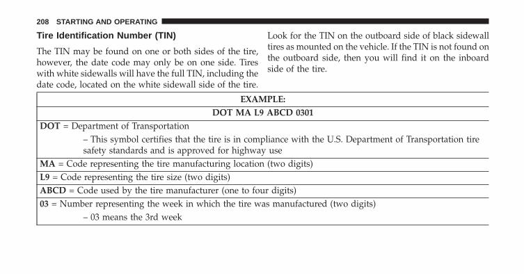
Tire Identification Number (TIN)
The TIN may be found on one or both sides of the tire,however, the date code may only be on one side. Tireswith white sidewalls will have the full TIN, including thedate code, located on the white sidewall side of the tire.
Look for the TIN on the outboard side of black sidewalltires as mounted on the vehicle. If the TIN is not found onthe outboard side, then you will find it on the inboardside of the tire.
EXAMPLE:DOT MA L9 ABCD 0301
DOT = Department of Transportation– This symbol certifies that the tire is in compliance with the U.S. Department of Transportation tiresafety standards and is approved for highway use
MA = Code representing the tire manufacturing location (two digits)L9 = Code representing the tire size (two digits)ABCD = Code used by the tire manufacturer (one to four digits)03 = Number representing the week in which the tire was manufactured (two digits)
– 03 means the 3rd week
208 STARTING AND OPERATING
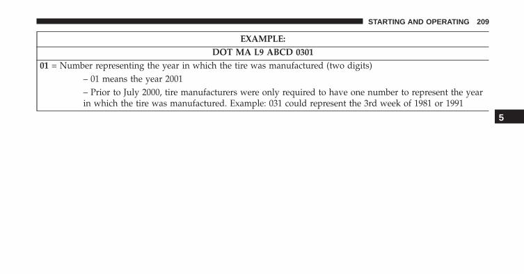
EXAMPLE:DOT MA L9 ABCD 0301
01 = Number representing the year in which the tire was manufactured (two digits)– 01 means the year 2001– Prior to July 2000, tire manufacturers were only required to have one number to represent the yearin which the tire was manufactured. Example: 031 could represent the 3rd week of 1981 or 1991
5
STARTING AND OPERATING 209
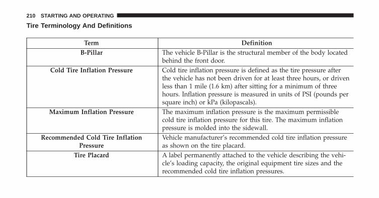
Tire Terminology And Definitions
Term DefinitionB-Pillar The vehicle B-Pillar is the structural member of the body located
behind the front door.Cold Tire Inflation Pressure Cold tire inflation pressure is defined as the tire pressure after
the vehicle has not been driven for at least three hours, or drivenless than 1 mile (1.6 km) after sitting for a minimum of threehours. Inflation pressure is measured in units of PSI (pounds persquare inch) or kPa (kilopascals).
Maximum Inflation Pressure The maximum inflation pressure is the maximum permissiblecold tire inflation pressure for this tire. The maximum inflationpressure is molded into the sidewall.
Recommended Cold Tire InflationPressure
Vehicle manufacturer’s recommended cold tire inflation pressureas shown on the tire placard.
Tire Placard A label permanently attached to the vehicle describing the vehi-cle’s loading capacity, the original equipment tire sizes and therecommended cold tire inflation pressures.
210 STARTING AND OPERATING
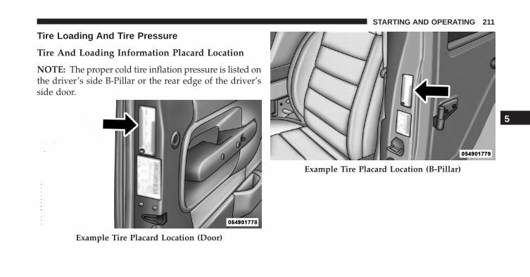
Tire Loading And Tire Pressure
Tire And Loading Information Placard Location
NOTE: The proper cold tire inflation pressure is listed onthe driver’s side B-Pillar or the rear edge of the driver’sside door.
Example Tire Placard Location (Door)
Example Tire Placard Location (B-Pillar)
5
STARTING AND OPERATING 211
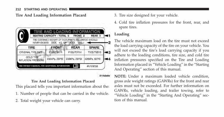
Tire And Loading Information Placard
This placard tells you important information about the:
1. Number of people that can be carried in the vehicle.
2. Total weight your vehicle can carry.
3. Tire size designed for your vehicle.
4. Cold tire inflation pressures for the front, rear, andspare tires.
Loading
The vehicle maximum load on the tire must not exceedthe load carrying capacity of the tire on your vehicle. Youwill not exceed the tire’s load carrying capacity if youadhere to the loading conditions, tire size, and cold tireinflation pressures specified on the Tire and LoadingInformation placard in “Vehicle Loading” in the “StartingAnd Operating” section of this manual.
NOTE: Under a maximum loaded vehicle condition,gross axle weight ratings (GAWRs) for the front and rearaxles must not be exceeded. For further information onGAWRs, vehicle loading, and trailer towing, refer to“Vehicle Loading” in the “Starting And Operating” sec-tion of this manual.
Tire And Loading Information Placard
212 STARTING AND OPERATING
To determine the maximum loading conditions of yourvehicle, locate the statement “The combined weight ofoccupants and cargo should never exceed XXX kg orXXX lbs” on the Tire and Loading Information placard.The combined weight of occupants, cargo/luggage andtrailer tongue weight (if applicable) should never exceedthe weight referenced here.
Steps For Determining Correct Load Limit—
(1) Locate the statement “The combined weight ofoccupants and cargo should never exceed XXX kg orXXX lbs.” on your vehicle’s placard.
(2) Determine the combined weight of the driver andpassengers that will be riding in your vehicle.
(3) Subtract the combined weight of the driver andpassengers from XXX kg or XXX lbs.
(4) The resulting figure equals the available amount ofcargo and luggage load capacity. For example, if“XXX” amount equals 1400 lbs. and there will be five150 lb passengers in your vehicle, the amount ofavailable cargo and luggage load capacity is 650 lbs.(1400-750 (5x150) = 650 lbs.)
(5) Determine the combined weight of luggage andcargo being loaded on the vehicle. That weight maynot safely exceed the available cargo and luggage loadcapacity calculated in Step 4.
(6) If your vehicle will be towing a trailer, load fromyour trailer will be transferred to your vehicle. Con-sult this manual to determine how this reduces theavailable cargo and luggage load capacity of yourvehicle.
5
STARTING AND OPERATING 213
Metric Example For Load Limit
For example, if “XXX” amount equals 635 kg and therewill be five 68 kg passengers in your vehicle, the amountof available cargo and luggage load capacity is 295 kg(635-340 (5x68) = 295 kg) as shown in step 4.
NOTE:
• If your vehicle will be towing a trailer, load from yourtrailer will be transferred to your vehicle. The follow-ing table shows examples on how to calculate totalload, cargo/luggage, and towing capacities of yourvehicle with varying seating configurations and num-ber and size of occupants. This table is for illustrationpurposes only and may not be accurate for the seatingand load carry capacity of your vehicle.
• For the following example, the combined weight ofoccupants and cargo should never exceed 865 lbs(392 kg).
214 STARTING AND OPERATING
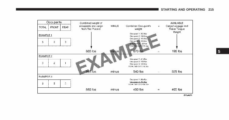
5
STARTING AND OPERATING 215
WARNING!
Overloading of your tires is dangerous. Overloading cancause tire failure, affect vehicle handling, and increaseyour stopping distance. Use tires of the recommendedload capacity for your vehicle. Never overload them.
TIRES — GENERAL INFORMATION
Tire Pressure
Proper tire inflation pressure is essential to the safe andsatisfactory operation of your vehicle. Four primary areasare affected by improper tire pressure:
• Safety and Vehicle Stability
• Economy
• Tread Wear
• Ride Comfort
Safety
WARNING!
• Improperly inflated tires are dangerous and cancause collisions.
• Underinflation increases tire flexing and can resultin overheating and tire failure.
• Overinflation reduces a tire’s ability to cushionshock. Objects on the road and chuckholes cancause damage that result in tire failure.
• Overinflated or underinflated tires can affect ve-hicle handling and can fail suddenly, resulting inloss of vehicle control.
• Unequal tire pressures can cause steering prob-lems. You could lose control of your vehicle.
(Continued)
216 STARTING AND OPERATING
WARNING! (Continued)• Unequal tire pressures from one side of the vehicle
to the other can cause the vehicle to drift to theright or left.
• Always drive with each tire inflated to the recom-mended cold tire inflation pressure.
Both under-inflation and over-inflation affect the stabilityof the vehicle and can produce a feeling of sluggishresponse or over responsiveness in the steering.
NOTE:
• Unequal tire pressures from side to side may causeerratic and unpredictable steering response.
• Unequal tire pressure from side to side may cause thevehicle to drift left or right.
Fuel Economy
Underinflated tires will increase tire rolling resistanceresulting in higher fuel consumption.
Tread Wear
Improper cold tire inflation pressures can cause abnor-mal wear patterns and reduced tread life, resulting in theneed for earlier tire replacement.
Ride Comfort And Vehicle Stability
Proper tire inflation contributes to a comfortable ride.Over-inflation produces a jarring and uncomfortableride.
5
STARTING AND OPERATING 217
Tire Inflation Pressures
The proper cold tire inflation pressure is listed on thedriver’s side B-Pillar or rear edge of the driver’s side door.
At least once a month:
• Check and adjust tire pressure with a good qualitypocket-type pressure gauge. Do not make a visualjudgement when determining proper inflation. Tiresmay look properly inflated even when they are under-inflated.
• Inspect tires for signs of tire wear or visible damage.
CAUTION!
After inspecting or adjusting the tire pressure, al-ways reinstall the valve stem cap. This will preventmoisture and dirt from entering the valve stem,which could damage the valve stem.
Inflation pressures specified on the placard are always“cold tire inflation pressure”. Cold tire inflation pressureis defined as the tire pressure after the vehicle has notbeen driven for at least three hours, or driven less than 1mile (1.6 km) after sitting for a minimum of three hours.The cold tire inflation pressure must not exceed themaximum inflation pressure molded into the tire side-wall.
Check tire pressures more often if subject to a wide rangeof outdoor temperatures, as tire pressures vary withtemperature changes.
Tire pressures change by approximately 1 psi (7 kPa) per12°F (7°C) of air temperature change. Keep this in mindwhen checking tire pressure inside a garage, especially inthe Winter.
218 STARTING AND OPERATING
Example: If garage temperature = 68°F (20°C) and theoutside temperature = 32°F (0°C) then the cold tireinflation pressure should be increased by 3 psi (21 kPa),which equals 1 psi (7 kPa) for every 12°F (7°C) for thisoutside temperature condition.
Tire pressure may increase from 2 to 6 psi (13 to 40 kPa)during operation. DO NOT reduce this normal pressurebuild up or your tire pressure will be too low.
Tire Pressures For High Speed Operation
The manufacturer advocates driving at safe speeds andwithin posted speed limits. Where speed limits or condi-tions are such that the vehicle can be driven at highspeeds, maintaining correct tire inflation pressure is veryimportant. Increased tire pressure and reduced vehicleloading may be required for high-speed vehicle opera-tion. Refer to your authorized tire dealer or originalequipment vehicle dealer for recommended safe operat-ing speeds, loading and cold tire inflation pressures.
WARNING!
High speed driving with your vehicle under maxi-mum load is dangerous. The added strain on yourtires could cause them to fail. You could have aserious collision. Do not drive a vehicle loaded to themaximum capacity at continuous speeds above75 mph (120 km/h).
Radial Ply Tires
WARNING!
Combining radial ply tires with other types of tireson your vehicle will cause your vehicle to handlepoorly. The instability could cause a collision. Al-ways use radial ply tires in sets of four. Nevercombine them with other types of tires.
5
STARTING AND OPERATING 219
Tire Repair
If your tire becomes damaged, it may be repaired if itmeets the following criteria:
• The tire has not been driven on when flat.
• The damage is only on the tread section of your tire(sidewall damage is not repairable).
• The puncture is no greater than a ¼ of an inch (6 mm).
Consult an authorized tire dealer for tire repairs andadditional information.
Damaged Run Flat tires, or Run Flat tires that haveexperienced a loss of pressure should be replaced imme-diately with another Run Flat tire of identical size andservice description (Load Index and Speed Symbol).
Tire Types
All Season Tires — If Equipped
All Season tires provide traction for all seasons (Spring,Summer, Fall and Winter). Traction levels may varybetween different all season tires. All season tires can beidentified by the M+S, M&S, M/S or MS designation onthe tire sidewall. Use all season tires only in sets of four;failure to do so may adversely affect the safety andhandling of your vehicle.
Summer Or Three Season Tires — If Equipped
Summer tires provide traction in both wet and dryconditions, and are not intended to be driven in snow oron ice. If your vehicle is equipped with Summer tires, beaware these tires are not designed for Winter or colddriving conditions. Install Winter tires on your vehiclewhen ambient temperatures are less than 40°F (5°C) or ifroads are covered with ice or snow. For more informa-tion, contact an authorized dealer.
220 STARTING AND OPERATING
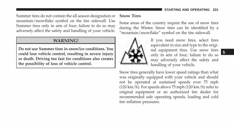
Summer tires do not contain the all season designation ormountain/snowflake symbol on the tire sidewall. UseSummer tires only in sets of four; failure to do so mayadversely affect the safety and handling of your vehicle.
WARNING!
Do not use Summer tires in snow/ice conditions. Youcould lose vehicle control, resulting in severe injuryor death. Driving too fast for conditions also createsthe possibility of loss of vehicle control.
Snow Tires
Some areas of the country require the use of snow tiresduring the Winter. Snow tires can be identified by a“mountain/snowflake” symbol on the tire sidewall.
If you need snow tires, select tiresequivalent in size and type to the origi-nal equipment tires. Use snow tiresonly in sets of four; failure to do somay adversely affect the safety andhandling of your vehicle.
Snow tires generally have lower speed ratings than whatwas originally equipped with your vehicle and shouldnot be operated at sustained speeds over 75 mph(120 km/h). For speeds above 75 mph (120 km/h) refer tooriginal equipment or an authorized tire dealer forrecommended safe operating speeds, loading and coldtire inflation pressures.
5
STARTING AND OPERATING 221
While studded tires improve performance on ice, skidand traction capability on wet or dry surfaces may bepoorer than that of non-studded tires. Some states pro-hibit studded tires; therefore, local laws should bechecked before using these tire types.
Run Flat Tires — If Equipped
Run Flat tires allow you the capability to drive 50 miles(80 km) at 50 mph (80 km/h) after a rapid loss of inflationpressure. This rapid loss of inflation is referred to as theRun Flat mode. A Run Flat mode occurs when the tireinflation pressure is of/or below 14 psi (96 kPa). Once aRun Flat tire reaches the run flat mode it has limiteddriving capabilities and needs to be replaced immedi-ately. A Run Flat tire is not repairable.
It is not recommended driving a vehicle loaded at fullcapacity or to tow a trailer while a tire is in the run flat mode.
See the tire pressure monitoring section for more infor-mation.
Spare Tires — If Equipped
NOTE: For vehicles equipped with Tire Service Kitinstead of a spare tire, please refer to “Tire Service Kit” in“What To Do In Emergencies” for further information.
CAUTION!
Because of the reduced ground clearance, do not takeyour vehicle through an automatic car wash with acompact or limited-use temporary spare installed.Damage to the vehicle may result.
Spare Tire Matching Original Equipped Tire AndWheel — If Equipped
Your vehicle may be equipped with a spare tire andwheel equivalent in look and function to the originalequipment tire and wheel found on the front or rear axleof your vehicle. This spare tire may be used in the tire
222 STARTING AND OPERATING
rotation for your vehicle. If your vehicle has this option,refer to an authorized tire dealer for the recommendedtire rotation pattern.
Compact Spare Tire — If Equipped
The compact spare is for temporary emergency use only.You can identify if your vehicle is equipped with acompact spare by looking at the spare tire description onthe Tire and Loading Information Placard located on thedriver’s side door opening or on the sidewall of the tire.Compact spare tire descriptions begin with the letter “T”or “S” preceding the size designation. Example: T145/80D18 103M.
T, S = Temporary Spare Tire
Since this tire has limited tread life, the original equip-ment tire should be repaired (or replaced) and reinstalledon your vehicle at the first opportunity.
Do not install a wheel cover or attempt to mount aconventional tire on the compact spare wheel, since thewheel is designed specifically for the compact spare tire.Do not install more than one compact spare tire andwheel on the vehicle at any given time.
WARNING!
Compact spares are for temporary emergency useonly. With these spares, do not drive more than50 mph (80 km/h). Temporary use spares have limitedtread life. When the tread is worn to the tread wearindicators, the temporary use spare tire needs to bereplaced. Be sure to follow the warnings, whichapply to your spare. Failure to do so could result inspare tire failure and loss of vehicle control.
5
STARTING AND OPERATING 223
Full Size Spare — If Equipped
The full size spare is for temporary emergency use only.This tire may look like the originally equipped tire on thefront or rear axle of your vehicle, but it is not. This sparetire may have limited tread life. When the tread is wornto the tread wear indicators, the temporary use full sizespare tire needs to be replaced. Since it is not the same asyour original equipment tire, replace (or repair) theoriginal equipment tire and reinstall on the vehicle at thefirst opportunity.
Limited Use Spare — If Equipped
The limited-use spare tire is for temporary emergencyuse only. This tire is identified by a label located on thelimited-use spare wheel. This label contains the drivinglimitations for this spare. This tire may look like theoriginal equipped tire on the front or rear axle of yourvehicle, but it is not. Installation of this limited-use sparetire affects vehicle handling. Since it is not the same as
your original equipment tire, replace (or repair) theoriginal equipment tire and reinstall on the vehicle at thefirst opportunity.
WARNING!
Limited-use spares are for emergency use only. In-stallation of this limited-use spare tire affects vehiclehandling. With this tire, do not drive more than thespeed listed on the limit-use spare wheel. Keepinflated to the cold tire inflation pressures listed onyour Tire and Loading Information Placard locatedon the driver’s side B-Pillar or the rear edge of thedriver’s side door. Replace (or repair) the originalequipment tire at the first opportunity and reinstall iton your vehicle. Failure to do so could result in lossof vehicle control.
224 STARTING AND OPERATING
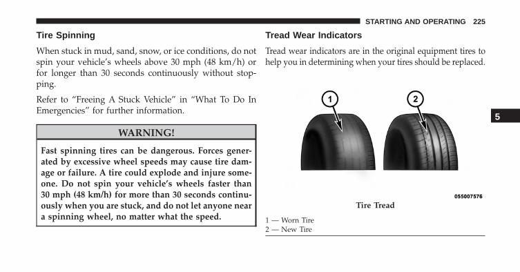
Tire Spinning
When stuck in mud, sand, snow, or ice conditions, do notspin your vehicle’s wheels above 30 mph (48 km/h) orfor longer than 30 seconds continuously without stop-ping.
Refer to “Freeing A Stuck Vehicle” in “What To Do InEmergencies” for further information.
WARNING!
Fast spinning tires can be dangerous. Forces gener-ated by excessive wheel speeds may cause tire dam-age or failure. A tire could explode and injure some-one. Do not spin your vehicle’s wheels faster than30 mph (48 km/h) for more than 30 seconds continu-ously when you are stuck, and do not let anyone neara spinning wheel, no matter what the speed.
Tread Wear Indicators
Tread wear indicators are in the original equipment tires tohelp you in determining when your tires should be replaced.
Tire Tread
1 — Worn Tire2 — New Tire
5
STARTING AND OPERATING 225
These indicators are molded into the bottom of the treadgrooves. They will appear as bands when the tread depthbecomes a 1/16 of an inch (1.6 mm). When the tread isworn to the tread wear indicators, the tire should bereplaced. Refer to “Replacement Tires” in this section forfurther information.
Life Of Tire
The service life of a tire is dependent upon varyingfactors including, but not limited to:
• Driving style.
• Tire pressure - Improper cold tire inflation pressurescan cause uneven wear patterns to develop across thetire tread. These abnormal wear patterns will reducetread life, resulting in the need for earlier tire replace-ment.
• Distance driven.
• Performance tires, tires with a speed rating of V orhigher, and Summer tires typically have a reducedtread life. Rotation of these tires per the vehicle main-tenance schedule is highly recommended.
WARNING!
Tires and the spare tire should be replaced after sixyears, regardless of the remaining tread. Failure tofollow this warning can result in sudden tire failure.You could lose control and have a collision resultingin serious injury or death.
Keep dismounted tires in a cool, dry place with as littleexposure to light as possible. Protect tires from contactwith oil, grease, and gasoline.
226 STARTING AND OPERATING
Replacement Tires
The tires on your new vehicle provide a balance of manycharacteristics. They should be inspected regularly forwear and correct cold tire inflation pressures. The manu-facturer strongly recommends that you use tires equiva-lent to the originals in size, quality and performancewhen replacement is needed. Refer to the paragraph on“Tread Wear Indicator”. Refer to the Tire and LoadingInformation placard or the Vehicle Certification Label forthe size designation of your tire. The Load Index andSpeed Symbol for your tire will be found on the originalequipment tire sidewall. See the Tire Sizing Chart ex-ample found in the “Tire Safety Information” section ofthis manual for more information relating to the LoadIndex and Speed Symbol of a tire.
It is recommended to replace the two front tires or tworear tires as a pair. Replacing just one tire can seriously
affect your vehicle’s handling. If you ever replace awheel, make sure that the wheel’s specifications matchthose of the original wheels.
It is recommended you contact your authorized tiredealer or original equipment dealer with any questionsyou may have on tire specifications or capability. Failureto use equivalent replacement tires may adversely affectthe safety, handling, and ride of your vehicle.
WARNING!
• Do not use a tire, wheel size or rating other thanthat specified for your vehicle. Some combinationsof unapproved tires and wheels may change sus-pension dimensions and performance characteris-tics, resulting in changes to steering, handling, and
(Continued)
5
STARTING AND OPERATING 227
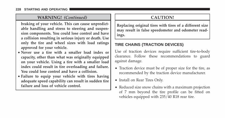
WARNING! (Continued)braking of your vehicle. This can cause unpredict-able handling and stress to steering and suspen-sion components. You could lose control and havea collision resulting in serious injury or death. Useonly the tire and wheel sizes with load ratingsapproved for your vehicle.
• Never use a tire with a smaller load index orcapacity, other than what was originally equippedon your vehicle. Using a tire with a smaller loadindex could result in tire overloading and failure.You could lose control and have a collision.
• Failure to equip your vehicle with tires havingadequate speed capability can result in sudden tirefailure and loss of vehicle control.
CAUTION!
Replacing original tires with tires of a different sizemay result in false speedometer and odometer read-ings.
TIRE CHAINS (TRACTION DEVICES)
Use of traction devices require sufficient tire-to-bodyclearance. Follow these recommendations to guardagainst damage.
• Traction device must be of proper size for the tire, asrecommended by the traction device manufacturer.
• Install on Rear Tires Only.
• Reduced size snow chains with a maximum projectionof 7 mm beyond the tire profile can be fitted onvehicles equipped with 235/40 R18 rear tire.
228 STARTING AND OPERATING
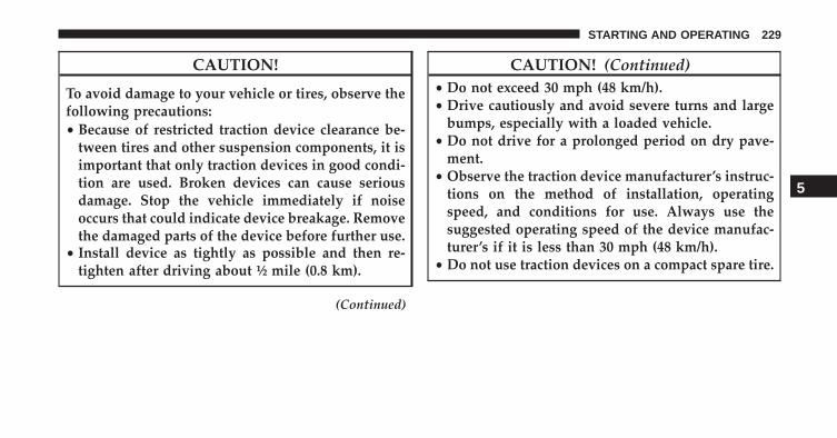
CAUTION!
To avoid damage to your vehicle or tires, observe thefollowing precautions:• Because of restricted traction device clearance be-
tween tires and other suspension components, it isimportant that only traction devices in good condi-tion are used. Broken devices can cause seriousdamage. Stop the vehicle immediately if noiseoccurs that could indicate device breakage. Removethe damaged parts of the device before further use.
• Install device as tightly as possible and then re-tighten after driving about ½ mile (0.8 km).
(Continued)
CAUTION! (Continued)• Do not exceed 30 mph (48 km/h).• Drive cautiously and avoid severe turns and large
bumps, especially with a loaded vehicle.• Do not drive for a prolonged period on dry pave-
ment.• Observe the traction device manufacturer’s instruc-
tions on the method of installation, operatingspeed, and conditions for use. Always use thesuggested operating speed of the device manufac-turer’s if it is less than 30 mph (48 km/h).
• Do not use traction devices on a compact spare tire.
5
STARTING AND OPERATING 229
TIRE ROTATION RECOMMENDATIONS
Due to tire design and size, tire rotations on this vehicleare not possible.
NOTE: For AR 4C models, where available, the vehiclemay be equipped with high performance tires that guar-antee high grip performance with little increase of wear.Alfa Romeo, in collaboration with Pirelli, developed aspecific high performance tire for the 4C model. Adedicated Pirelli PZero, identified with an AR mark,guarantees this vehicle to obtain the highest performancecapable.
TIRE PRESSURE MONITORING SYSTEM (TPMS)
The Tire Pressure Monitor System (TPMS) will warn thedriver of a low tire pressure based on the vehicle recom-mended cold tire pressure.
The tire pressure will vary with temperature by about 1psi (7 kPa) for every 12°F (6.5°C). This means that when
the outside temperature decreases, the tire pressure willdecrease. Tire pressure should always be set based oncold inflation tire pressure. This is defined as the tirepressure after the vehicle has not been driven for at leastthree hours, or driven less than 1 mile (1.6 km) after athree hour period. The cold tire inflation pressure mustnot exceed the maximum inflation pressure molded intothe tire sidewall. Refer to “Tires – General Information”in “Starting And Operating” for information on how toproperly inflate the vehicle’s tires. The tire pressure willalso increase as the vehicle is driven, this is normal andthere should be no adjustment for this increased pres-sure.
The TPMS will warn the driver of a low tire pressure ifthe tire pressure falls below the low pressure warninglimit for any reason, including low temperature effects, ornatural pressure loss through the tire.
230 STARTING AND OPERATING
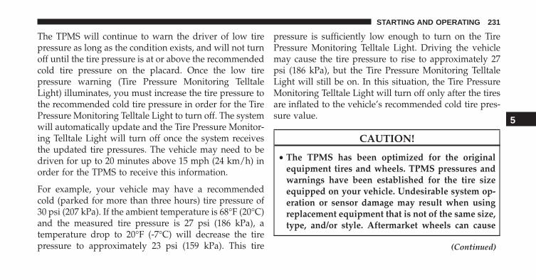
The TPMS will continue to warn the driver of low tirepressure as long as the condition exists, and will not turnoff until the tire pressure is at or above the recommendedcold tire pressure on the placard. Once the low tirepressure warning (Tire Pressure Monitoring TelltaleLight) illuminates, you must increase the tire pressure tothe recommended cold tire pressure in order for the TirePressure Monitoring Telltale Light to turn off. The systemwill automatically update and the Tire Pressure Monitor-ing Telltale Light will turn off once the system receivesthe updated tire pressures. The vehicle may need to bedriven for up to 20 minutes above 15 mph (24 km/h) inorder for the TPMS to receive this information.
For example, your vehicle may have a recommendedcold (parked for more than three hours) tire pressure of30 psi (207 kPa). If the ambient temperature is 68°F (20°C)and the measured tire pressure is 27 psi (186 kPa), atemperature drop to 20°F (-7°C) will decrease the tirepressure to approximately 23 psi (159 kPa). This tire
pressure is sufficiently low enough to turn on the TirePressure Monitoring Telltale Light. Driving the vehiclemay cause the tire pressure to rise to approximately 27psi (186 kPa), but the Tire Pressure Monitoring TelltaleLight will still be on. In this situation, the Tire PressureMonitoring Telltale Light will turn off only after the tiresare inflated to the vehicle’s recommended cold tire pres-sure value.
CAUTION!
• The TPMS has been optimized for the originalequipment tires and wheels. TPMS pressures andwarnings have been established for the tire sizeequipped on your vehicle. Undesirable system op-eration or sensor damage may result when usingreplacement equipment that is not of the same size,type, and/or style. Aftermarket wheels can cause
(Continued)
5
STARTING AND OPERATING 231
CAUTION! (Continued)sensor damage. Using aftermarket tire sealants maycause the Tire Pressure Monitoring System (TPMS)sensor to become inoperable. After using an after-market tire sealant it is recommended that you takeyour vehicle to an authorized dealership to haveyour sensor function checked.
• After inspecting or adjusting the tire pressure,always reinstall the valve stem cap. This willprevent moisture and dirt from entering the valvestem, which could damage the Tire Pressure Moni-toring Sensor.
NOTE:
• The TPMS is not intended to replace normal tire careand maintenance, or to provide warning of a tirefailure or condition.
• The TPMS should not be used as a tire pressure gaugewhile adjusting your tire pressure.
• Driving on a significantly under-inflated tire causesthe tire to overheat and can lead to tire failure.Under-inflation also reduces fuel efficiency and tiretread life, and may affect the vehicle’s handling andstopping ability.
• The TPMS is not a substitute for proper tire mainte-nance, and it is the driver’s responsibility to maintaincorrect tire pressure using an accurate tire gauge, evenif under-inflation has not reached the level to triggerillumination of the Tire Pressure Monitoring TelltaleLight.
• Seasonal temperature changes will affect tire pressure,and the TPMS will monitor the actual tire pressure inthe tire.
232 STARTING AND OPERATING
Base System
This is the TPMS warning indicator located in theinstrument cluster.
The TPMS uses wireless technology with wheel rimmounted electronic sensors to monitor tire pressure lev-els. Sensors, mounted to each wheel as part of the valvestem, transmit tire pressure readings to the ReceiverModule.
NOTE: It is particularly important for you to check thetire pressure in all of the tires on your vehicle regularlyand to maintain the proper pressure.
The TPMS consists of the following components:
• Receiver Module.
• Four Tire Pressure Monitoring Sensors.
• Tire Pressure Monitoring Telltale Light.
Tire Pressure Monitoring Low Pressure Warnings
The Tire Pressure Monitoring Telltale Light will illumi-nate in the instrument cluster, an acoustic signal will beactivated, and the “Check left or right front/rear tire”text message will display when one or more of the fouractive road tire pressures are low. Should this occur, youshould stop as soon as possible, check the inflationpressure of each tire on your vehicle, and inflate each tireto the vehicle’s recommended cold placard pressurevalue. The system will automatically update and the TirePressure Monitoring Light will extinguish once the up-dated tire pressures have been received. The vehicle mayneed to be driven for up to 20 minutes above 15 mph(24 km/h) to receive this information.
Check TPMS Warnings
The Tire Pressure Monitoring Telltale Light will flash onand off for 75 seconds and remain on solid when a systemfault is detected, the “TIRE PRESSURE MONITORING
5
STARTING AND OPERATING 233
UNAVAILABLE” text message will display. If the igni-tion key is cycled, this sequence will repeat providing thesystem fault still exists. The Tire Pressure MonitoringTelltale Light will turn off when the fault condition nolonger exists. A system fault can occur with any of thefollowing scenarios:
1. Jamming due to electronic devices or driving next tofacilities emitting the same radio frequencies as theTPM sensors.
2. Installing some form of aftermarket window tintingthat affects radio wave signals.
3. Snow or ice around the wheels or wheel housings.
4. Using tire chains on the vehicle.
5. Using wheels/tires not equipped with TPM sensors.
NOTE: Your vehicle may be equipped with a compactspare wheel and tire assembly.
1. The compact spare tire does not have a tire pressuremonitoring sensor. Therefore, the TPMS will not moni-tor the tire pressure in the compact spare tire.
2. If you install the compact spare tire in place of a roadtire that has a pressure below the low-pressure warn-ing limit, upon the next ignition key cycle, a chime willsound and the Tire Pressure Monitoring Telltale Lightwill still turn ON due to the low tire.
3. However, after driving the vehicle for up to 20 min-utes above 15 mph (24 km/h), the Tire PressureMonitoring Telltale Light will flash on and off for 75seconds and then remain on solid.
4. This occurs for each subsequent ignition key cycle, achime will sound and the Tire Pressure MonitoringTelltale Light will flash on and off for 75 seconds andthen remain on solid.
234 STARTING AND OPERATING
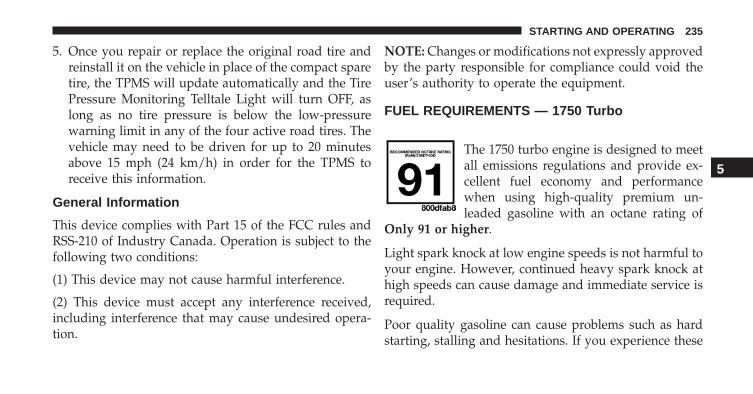
5. Once you repair or replace the original road tire andreinstall it on the vehicle in place of the compact sparetire, the TPMS will update automatically and the TirePressure Monitoring Telltale Light will turn OFF, aslong as no tire pressure is below the low-pressurewarning limit in any of the four active road tires. Thevehicle may need to be driven for up to 20 minutesabove 15 mph (24 km/h) in order for the TPMS toreceive this information.
General Information
This device complies with Part 15 of the FCC rules andRSS-210 of Industry Canada. Operation is subject to thefollowing two conditions:
(1) This device may not cause harmful interference.
(2) This device must accept any interference received,including interference that may cause undesired opera-tion.
NOTE: Changes or modifications not expressly approvedby the party responsible for compliance could void theuser’s authority to operate the equipment.
FUEL REQUIREMENTS — 1750 Turbo
The 1750 turbo engine is designed to meetall emissions regulations and provide ex-cellent fuel economy and performancewhen using high-quality premium un-leaded gasoline with an octane rating of
Only 91 or higher.
Light spark knock at low engine speeds is not harmful toyour engine. However, continued heavy spark knock athigh speeds can cause damage and immediate service isrequired.
Poor quality gasoline can cause problems such as hardstarting, stalling and hesitations. If you experience these
5
STARTING AND OPERATING 235
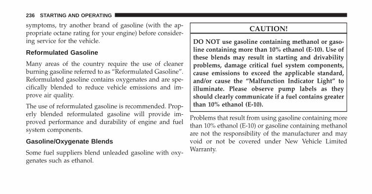
symptoms, try another brand of gasoline (with the ap-propriate octane rating for your engine) before consider-ing service for the vehicle.
Reformulated Gasoline
Many areas of the country require the use of cleanerburning gasoline referred to as “Reformulated Gasoline”.Reformulated gasoline contains oxygenates and are spe-cifically blended to reduce vehicle emissions and im-prove air quality.
The use of reformulated gasoline is recommended. Prop-erly blended reformulated gasoline will provide im-proved performance and durability of engine and fuelsystem components.
Gasoline/Oxygenate Blends
Some fuel suppliers blend unleaded gasoline with oxy-genates such as ethanol.
CAUTION!
DO NOT use gasoline containing methanol or gaso-line containing more than 10% ethanol (E-10). Use ofthese blends may result in starting and drivabilityproblems, damage critical fuel system components,cause emissions to exceed the applicable standard,and/or cause the “Malfunction Indicator Light” toilluminate. Please observe pump labels as theyshould clearly communicate if a fuel contains greaterthan 10% ethanol (E-10).
Problems that result from using gasoline containing morethan 10% ethanol (E-10) or gasoline containing methanolare not the responsibility of the manufacturer and mayvoid or not be covered under New Vehicle LimitedWarranty.
236 STARTING AND OPERATING
E-85 Usage In Non-Flex Fuel Vehicles
Non-Flex Fuel Vehicles (FFV) are compatible with gaso-line containing up to 10% ethanol (E-10). Gasoline withhigher ethanol content may void the New Vehicle Lim-ited Warranty.
If a Non-FFV vehicle is inadvertently fueled with E-85fuel, the engine will have some or all of these symptoms:
• Operate in a lean mode.
• OBD II “Malfunction Indicator Light” on.
• Poor engine performance.
• Poor cold start and cold drivability.
• Increased risk for fuel system component corrosion.
MMT In Gasoline
Methylcyclopentadienyl Manganese Tricarbonyl (MMT)is a manganese-containing metallic additive that isblended into some gasoline to increase octane. Gasolineblended with MMT provides no performance advantagebeyond gasoline of the same octane number withoutMMT. Gasoline blended with MMT reduces spark pluglife and reduces emissions system performance in somevehicles. The manufacturer recommends that gasolinewithout MMT be used in your vehicle. The MMT contentof gasoline may not be indicated on the gasoline pump,therefore, you should ask your gasoline retailer whetherthe gasoline contains MMT. MMT is prohibited in Federaland California reformulated gasoline.
5
STARTING AND OPERATING 237
Materials Added To Fuel
Besides using unleaded gasoline with the proper octanerating, gasolines that contain detergents, corrosion andstability additives are recommended. Using gasolinesthat have these additives will help improve fueleconomy, reduce emissions, and maintain vehicle perfor-mance. Designated TOP TIER Detergent Gasoline con-tains a higher level of detergents to further aide inminimizing engine and fuel system deposits. When avail-able the usage of Top Tier Detergent gasoline is recom-mended. Visit www.toptiergas.com for a list of TOP TIERDetergent Gasoline Retailers.
Indiscriminate use of fuel system cleaning agents shouldbe avoided. Many of these materials intended for gumand varnish removal may contain active solvents orsimilar ingredients. These can harm fuel system gasketand diaphragm materials.
Fuel System Cautions
CAUTION!
Follow these guidelines to maintain your vehicle’sperformance:• The use of leaded gasoline is prohibited by Federal
law. Using leaded gasoline can impair engine per-formance and damage the emissions control sys-tem.
• An out-of-tune engine or certain fuel or ignitionmalfunctions can cause the catalytic converter tooverheat. If you notice a pungent burning odor orsome light smoke, your engine may be out of tuneor malfunctioning and may require immediate ser-vice. Contact your authorized dealer for serviceassistance.
(Continued)
238 STARTING AND OPERATING
CAUTION! (Continued)• The use of fuel additives, which are now being
sold as octane enhancers, is not recommended.Most of these products contain high concentrationsof methanol. Fuel system damage or vehicle perfor-mance problems resulting from the use of suchfuels or additives is not the responsibility of themanufacturer and may void or not be coveredunder the New Vehicle Limited Warranty.
NOTE: Intentional tampering with the emissions controlsystem can result in civil penalties being assessed againstyou.
Carbon Monoxide Warnings
WARNING!
Carbon monoxide (CO) in exhaust gases is deadly.Follow the precautions below to prevent carbonmonoxide poisoning:• Do not inhale exhaust gases. They contain carbon
monoxide, a colorless and odorless gas, which cankill. Never run the engine in a closed area, such asa garage, and never sit in a parked vehicle with theengine running for an extended period. If thevehicle is stopped in an open area with the enginerunning for more than a short period, adjust theventilation system to force fresh, outside air intothe vehicle.
(Continued)
5
STARTING AND OPERATING 239
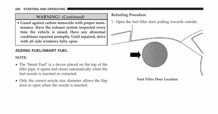
WARNING! (Continued)• Guard against carbon monoxide with proper main-
tenance. Have the exhaust system inspected everytime the vehicle is raised. Have any abnormalconditions repaired promptly. Until repaired, drivewith all side windows fully open.
ADDING FUEL/SMART FUEL
NOTE:
• The �Smart Fuel� is a device placed on the top of thefiller pipe, it opens and closes automatically when thefuel nozzle is inserted or extracted.
• Only the correct nozzle size diameter allows the flapdoor to open when the nozzle is inserted.
Refueling Procedure
1. Open the fuel filler door pulling towards outside.
Fuel Filler Door Location
240 STARTING AND OPERATING
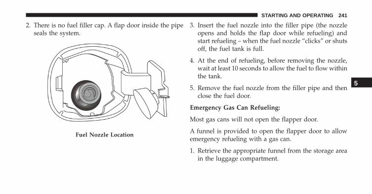
2. There is no fuel filler cap. A flap door inside the pipeseals the system.
3. Insert the fuel nozzle into the filler pipe (the nozzleopens and holds the flap door while refueling) andstart refueling – when the fuel nozzle “clicks” or shutsoff, the fuel tank is full.
4. At the end of refueling, before removing the nozzle,wait at least 10 seconds to allow the fuel to flow withinthe tank.
5. Remove the fuel nozzle from the filler pipe and thenclose the fuel door.
Emergency Gas Can Refueling:
Most gas cans will not open the flapper door.
A funnel is provided to open the flapper door to allowemergency refueling with a gas can.
1. Retrieve the appropriate funnel from the storage areain the luggage compartment.
Fuel Nozzle Location
5
STARTING AND OPERATING 241
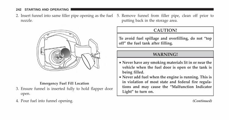
2. Insert funnel into same filler pipe opening as the fuelnozzle.
3. Ensure funnel is inserted fully to hold flapper dooropen.
4. Pour fuel into funnel opening.
5. Remove funnel from filler pipe, clean off prior toputting back in the storage area.
CAUTION!
To avoid fuel spillage and overfilling, do not “topoff” the fuel tank after filling.
WARNING!
• Never have any smoking materials lit in or near thevehicle when the fuel door is open or the tank isbeing filled.
• Never add fuel when the engine is running. This isin violation of most state and federal fire regula-tions and may cause the “Malfunction IndicatorLight” to turn on.
(Continued)
Emergency Fuel Fill Location
242 STARTING AND OPERATING
WARNING! (Continued)• A fire may result if fuel is pumped into a portable
container that is inside of a vehicle. You could beburned. Always place fuel containers on theground while filling.
TRAILER TOWING
Trailer towing with this vehicle is not recommended.
RECREATIONAL TOWING (BEHINDMOTORHOME, ETC.)
Towing This Vehicle Behind Another Vehicle
NOTE: This vehicle may be towed on a flatbed orvehicle trailer provided all four wheels are OFF theground.
CAUTION!
• DO NOT flat tow this vehicle. Damage to thedrivetrain will result.
• Do not dolly tow this vehicle. Use of a towing dollycan cause significant damage to your vehicle. Dam-age from improper towing is not covered under theNew Vehicle Limited Warranty.
• Towing this vehicle in violation of the above re-quirements can cause severe transmission damage.Damage from improper towing is not covered un-der the New Vehicle Limited Warranty.
5
STARTING AND OPERATING 243
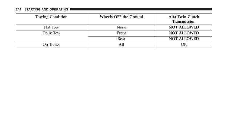
Towing Condition Wheels OFF the Ground Alfa Twin ClutchTransmission
Flat Tow None NOT ALLOWEDDolly Tow Front NOT ALLOWED
Rear NOT ALLOWEDOn Trailer All OK
244 STARTING AND OPERATING
WHAT TO DO IN EMERGENCIES
CONTENTS� HAZARD WARNING FLASHER . . . . . . . . . . .246
� IF YOUR ENGINE OVERHEATS . . . . . . . . . . . .246
� WHEEL AND TIRE TORQUESPECIFICATIONS . . . . . . . . . . . . . . . . . . . . . .248
▫ Torque Specifications . . . . . . . . . . . . . . . . . . .248
� TIRE SERVICE KIT . . . . . . . . . . . . . . . . . . . . . .249
� JUMP-STARTING . . . . . . . . . . . . . . . . . . . . . .254
▫ Preparations For Jump-Start . . . . . . . . . . . . . .254
▫ Jump-Starting Procedure . . . . . . . . . . . . . . . .256
� FRONT TOW EYE USAGE . . . . . . . . . . . . . . . .258
� FIRE EXTINGUISHER — IF EQUIPPED . . . . . . .261
� ENHANCED ACCIDENT RESPONSE SYSTEM(EARS) . . . . . . . . . . . . . . . . . . . . . . . . . . . . . .262
� EVENT DATA RECORDER (EDR) . . . . . . . . . . .262
6
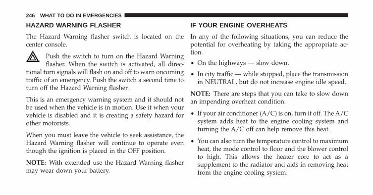
HAZARD WARNING FLASHER
The Hazard Warning flasher switch is located on thecenter console.
Push the switch to turn on the Hazard Warningflasher. When the switch is activated, all direc-
tional turn signals will flash on and off to warn oncomingtraffic of an emergency. Push the switch a second time toturn off the Hazard Warning flasher.
This is an emergency warning system and it should notbe used when the vehicle is in motion. Use it when yourvehicle is disabled and it is creating a safety hazard forother motorists.
When you must leave the vehicle to seek assistance, theHazard Warning flasher will continue to operate eventhough the ignition is placed in the OFF position.
NOTE: With extended use the Hazard Warning flashermay wear down your battery.
IF YOUR ENGINE OVERHEATS
In any of the following situations, you can reduce thepotential for overheating by taking the appropriate ac-tion.
• On the highways — slow down.
• In city traffic — while stopped, place the transmissionin NEUTRAL, but do not increase engine idle speed.
NOTE: There are steps that you can take to slow downan impending overheat condition:
• If your air conditioner (A/C) is on, turn it off. The A/Csystem adds heat to the engine cooling system andturning the A/C off can help remove this heat.
• You can also turn the temperature control to maximumheat, the mode control to floor and the blower controlto high. This allows the heater core to act as asupplement to the radiator and aids in removing heatfrom the engine cooling system.
246 WHAT TO DO IN EMERGENCIES
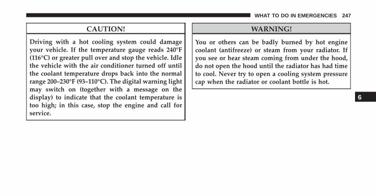
CAUTION!
Driving with a hot cooling system could damageyour vehicle. If the temperature gauge reads 240°F(116°C) or greater pull over and stop the vehicle. Idlethe vehicle with the air conditioner turned off untilthe coolant temperature drops back into the normalrange 200–230°F (93–110°C). The digital warning lightmay switch on (together with a message on thedisplay) to indicate that the coolant temperature istoo high; in this case, stop the engine and call forservice.
WARNING!
You or others can be badly burned by hot enginecoolant (antifreeze) or steam from your radiator. Ifyou see or hear steam coming from under the hood,do not open the hood until the radiator has had timeto cool. Never try to open a cooling system pressurecap when the radiator or coolant bottle is hot.
6
WHAT TO DO IN EMERGENCIES 247
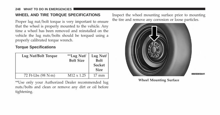
WHEEL AND TIRE TORQUE SPECIFICATIONS
Proper lug nut/bolt torque is very important to ensurethat the wheel is properly mounted to the vehicle. Anytime a wheel has been removed and reinstalled on thevehicle the lug nuts/bolts should be torqued using aproperly calibrated torque wrench.
Torque Specifications
Lug Nut/Bolt Torque **Lug Nut/Bolt Size
Lug Nut/Bolt
SocketSize
72 Ft-Lbs (98 N·m) M12 x 1.25 17 mm
**Use only your Authorized Dealer recommended lugnuts/bolts and clean or remove any dirt or oil beforetightening.
Inspect the wheel mounting surface prior to mountingthe tire and remove any corrosion or loose particles.
Wheel Mounting Surface
248 WHAT TO DO IN EMERGENCIES
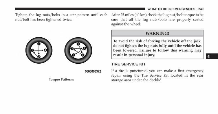
Tighten the lug nuts/bolts in a star pattern until eachnut/bolt has been tightened twice.
After 25 miles (40 km) check the lug nut/bolt torque to besure that all the lug nuts/bolts are properly seatedagainst the wheel.
WARNING!
To avoid the risk of forcing the vehicle off the jack,do not tighten the lug nuts fully until the vehicle hasbeen lowered. Failure to follow this warning mayresult in personal injury.
TIRE SERVICE KIT
If a tire is punctured, you can make a first emergencyrepair using the Tire Service Kit located in the rearstorage area under the decklid.Torque Patterns
6
WHAT TO DO IN EMERGENCIES 249
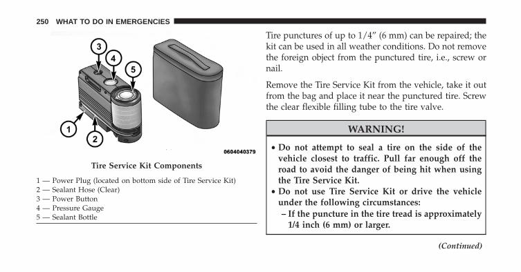
Tire punctures of up to 1/4” (6 mm) can be repaired; thekit can be used in all weather conditions. Do not removethe foreign object from the punctured tire, i.e., screw ornail.
Remove the Tire Service Kit from the vehicle, take it outfrom the bag and place it near the punctured tire. Screwthe clear flexible filling tube to the tire valve.
WARNING!
• Do not attempt to seal a tire on the side of thevehicle closest to traffic. Pull far enough off theroad to avoid the danger of being hit when usingthe Tire Service Kit.
• Do not use Tire Service Kit or drive the vehicleunder the following circumstances:– If the puncture in the tire tread is approximately
1/4 inch (6 mm) or larger.
(Continued)
Tire Service Kit Components
1 — Power Plug (located on bottom side of Tire Service Kit)2 — Sealant Hose (Clear)3 — Power Button4 — Pressure Gauge5 — Sealant Bottle
250 WHAT TO DO IN EMERGENCIES
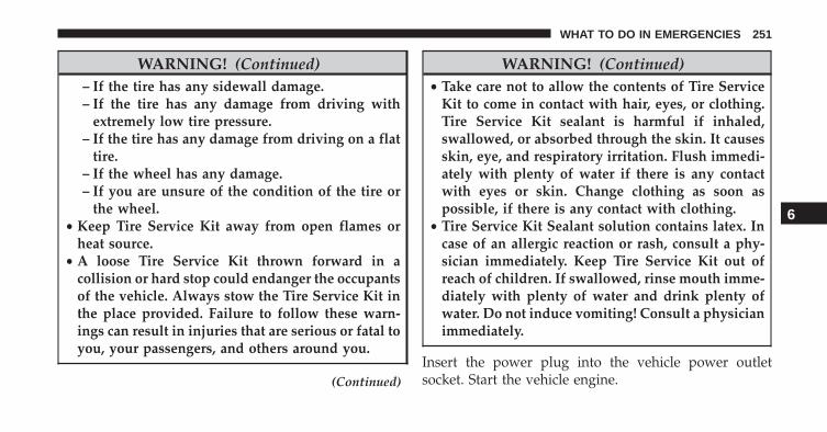
WARNING! (Continued)– If the tire has any sidewall damage.– If the tire has any damage from driving with
extremely low tire pressure.– If the tire has any damage from driving on a flat
tire.– If the wheel has any damage.– If you are unsure of the condition of the tire or
the wheel.• Keep Tire Service Kit away from open flames or
heat source.• A loose Tire Service Kit thrown forward in a
collision or hard stop could endanger the occupantsof the vehicle. Always stow the Tire Service Kit inthe place provided. Failure to follow these warn-ings can result in injuries that are serious or fatal toyou, your passengers, and others around you.
(Continued)
WARNING! (Continued)• Take care not to allow the contents of Tire Service
Kit to come in contact with hair, eyes, or clothing.Tire Service Kit sealant is harmful if inhaled,swallowed, or absorbed through the skin. It causesskin, eye, and respiratory irritation. Flush immedi-ately with plenty of water if there is any contactwith eyes or skin. Change clothing as soon aspossible, if there is any contact with clothing.
• Tire Service Kit Sealant solution contains latex. Incase of an allergic reaction or rash, consult a phy-sician immediately. Keep Tire Service Kit out ofreach of children. If swallowed, rinse mouth imme-diately with plenty of water and drink plenty ofwater. Do not induce vomiting! Consult a physicianimmediately.
Insert the power plug into the vehicle power outletsocket. Start the vehicle engine.
6
WHAT TO DO IN EMERGENCIES 251
Push the Tire Service Kit power button to the “I” position.The electric compressor will be turned on, sealant and airwill inflate the tire.
Minimum 26 psi (1.8 bar) of pressure should be reachedwithin 20 minutes. If the pressure has not been reachedturn off and remove the Tire Service Kit, drive the vehicle30 feet (10 meters) back and forth, to better distribute thesealant inside the tire.
Attach the clear flexible filling tube of the compressordirectly to the tire valve and repeat the inflation process.
When the correct pressure has been reached, start drivingthe vehicle to uniformly distribute the sealant inside thetire. After 10 minutes, stop and check the tire pressure. Ifthe pressure is below 19 psi (1.3 bar), do not drive thevehicle, as the tire is too damaged, contact the nearestAuthorized Dealer.
WARNING!
Tire Service Kit is not a permanent flat tire repair.Have the tire inspected and repaired or replaced afterusing Tire Service Kit. Do not exceed 65 mph(110 km/h) until the tire is repaired or replaced.Failure to follow this warning can result in injuriesthat are serious or fatal to you, your passengers, andothers around you. Have the tire checked as soon aspossible at an Authorized Dealer.
If the pressure is at 19 psi (1.3 bar) or above repeat theinflation process to reach the correct tire pressure andcontinue driving.
Peel off the warning label from the bottle and place it onthe dashboard as a reminder to the driver that the tire hasbeen treated with Tire Service Kit.
252 WHAT TO DO IN EMERGENCIES
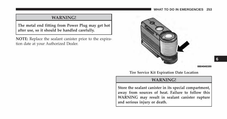
WARNING!
The metal end fitting from Power Plug may get hotafter use, so it should be handled carefully.
NOTE: Replace the sealant canister prior to the expira-tion date at your Authorized Dealer.
WARNING!
Store the sealant canister in its special compartment,away from sources of heat. Failure to follow thisWARNING may result in sealant canister ruptureand serious injury or death.
Tire Service Kit Expiration Date Location
6
WHAT TO DO IN EMERGENCIES 253
JUMP-STARTING
If your vehicle has a discharged battery it can be jump-started using a set of jumper cables and a battery inanother vehicle or by using a portable battery boosterpack. Jump-starting can be dangerous if done improperlyso please follow the procedures in this section carefully.
NOTE: When using a portable battery booster packfollow the manufacturer’s operating instructions andprecautions.
CAUTION!
Do not use a portable battery booster pack or anyother booster source with a system voltage greaterthan 12 Volts or damage to the battery, starter motor,alternator or electrical system may occur.
WARNING!
Do not attempt jump-starting if the battery is frozen.It could rupture or explode and cause personal injury.
Preparations For Jump-Start
The battery in your vehicle is located on the left side ofthe engine compartment. To access the battery removethe protective cover.
254 WHAT TO DO IN EMERGENCIES
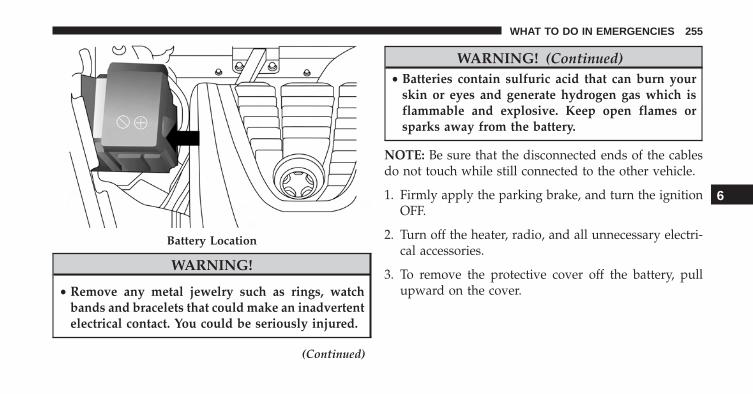
WARNING!
• Remove any metal jewelry such as rings, watchbands and bracelets that could make an inadvertentelectrical contact. You could be seriously injured.
(Continued)
WARNING! (Continued)• Batteries contain sulfuric acid that can burn your
skin or eyes and generate hydrogen gas which isflammable and explosive. Keep open flames orsparks away from the battery.
NOTE: Be sure that the disconnected ends of the cablesdo not touch while still connected to the other vehicle.
1. Firmly apply the parking brake, and turn the ignitionOFF.
2. Turn off the heater, radio, and all unnecessary electri-cal accessories.
3. To remove the protective cover off the battery, pullupward on the cover.
Battery Location
6
WHAT TO DO IN EMERGENCIES 255
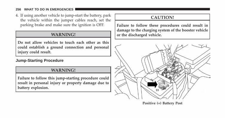
4. If using another vehicle to jump-start the battery, parkthe vehicle within the jumper cables reach, set theparking brake and make sure the ignition is OFF.
WARNING!
Do not allow vehicles to touch each other as thiscould establish a ground connection and personalinjury could result.
Jump-Starting Procedure
WARNING!
Failure to follow this jump-starting procedure couldresult in personal injury or property damage due tobattery explosion.
CAUTION!
Failure to follow these procedures could result indamage to the charging system of the booster vehicleor the discharged vehicle.
Positive (+) Battery Post
256 WHAT TO DO IN EMERGENCIES
Connecting The Jumper Cables
1. Connect the positive (+) end of the jumper cable to thepositive (+) post of the vehicle with the dischargedbattery.
2. Connect the opposite end of the positive (+) jumpercable to the positive (+) post of the booster battery.
3. Connect the negative end (-) of the jumper cable to thenegative (-) post of the booster battery.
4. Connect the opposite end of the negative (-) jumpercable to a good engine ground of the vehicle with thedischarged battery (exposed metal part of the engine)away from the battery and the fuel injection system.
WARNING!
Do not connect the jumper cable to the negative (-)post of the discharged battery. The resulting electri-cal spark could cause the battery to explode andcould result in personal injury. Only use the specificground point, do not use any other exposed metalparts.
5. Start the engine in the vehicle that has the boosterbattery, let the engine idle a few minutes, and thenstart the engine in the vehicle with the dischargedbattery.
6. Once the engine is started, remove the jumper cablesin the reverse sequence:
6
WHAT TO DO IN EMERGENCIES 257
Disconnecting The Jumper Cables
1. Disconnect the negative (-) jumper cable from theengine (-) ground of the vehicle with the dischargedbattery.
2. Disconnect the negative end (-) of the jumper cablefrom the negative (-) post of the booster battery.
3. Disconnect the opposite end of the positive (+) jumpercable from the positive (+) post of the booster battery.
4. Disconnect the positive (+) end of the jumper cablefrom the positive (+) post of the vehicle with thedischarged battery.
If frequent jump-starting is required to start your vehicleyou should have the battery and charging system in-spected at your authorized dealer.
CAUTION!
Accessories plugged into the vehicle power outletsdraw power from the vehicle’s battery, even when notin use (i.e., cellular devices, etc.). Eventually, ifplugged in long enough without engine operation,the vehicle’s battery will discharge sufficiently todegrade battery life and/or prevent the engine fromstarting.
FRONT TOW EYE USAGE
Your vehicle is equipped with a tow eye that can be usedto tow a disabled vehicle.
The front tow eye receptacle is located on the lower rightside of the front fascia.
To install the tow eye, thread the tow eye into thereceptacle.
258 WHAT TO DO IN EMERGENCIES
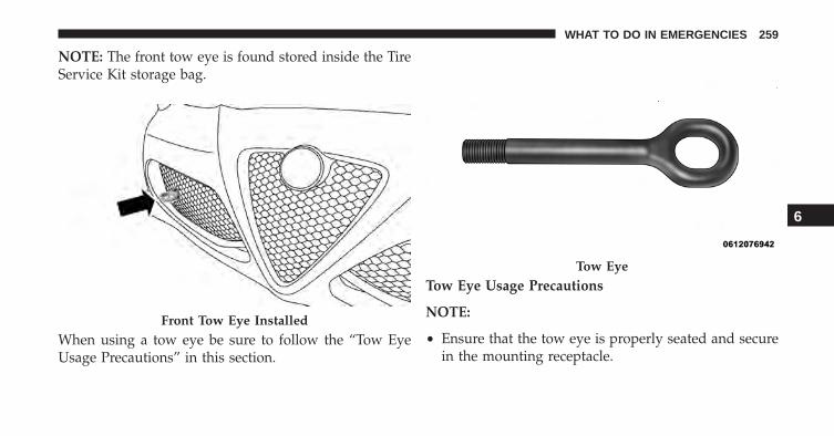
NOTE: The front tow eye is found stored inside the TireService Kit storage bag.
When using a tow eye be sure to follow the “Tow EyeUsage Precautions” in this section.
Tow Eye Usage Precautions
NOTE:
• Ensure that the tow eye is properly seated and securein the mounting receptacle.
Front Tow Eye Installed
Tow Eye
6
WHAT TO DO IN EMERGENCIES 259
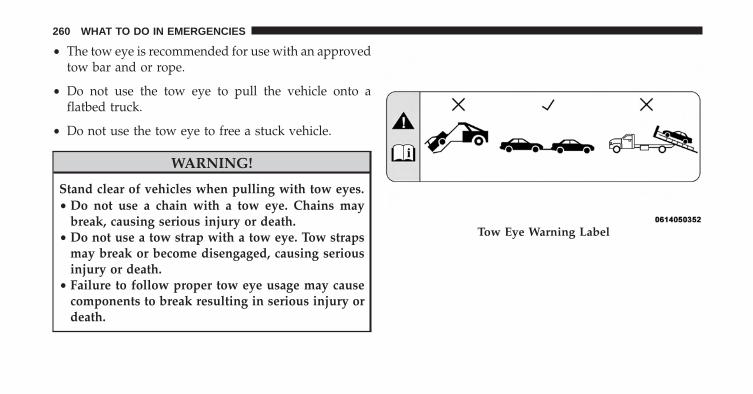
• The tow eye is recommended for use with an approvedtow bar and or rope.
• Do not use the tow eye to pull the vehicle onto aflatbed truck.
• Do not use the tow eye to free a stuck vehicle.
WARNING!
Stand clear of vehicles when pulling with tow eyes.• Do not use a chain with a tow eye. Chains may
break, causing serious injury or death.• Do not use a tow strap with a tow eye. Tow straps
may break or become disengaged, causing seriousinjury or death.
• Failure to follow proper tow eye usage may causecomponents to break resulting in serious injury ordeath.
Tow Eye Warning Label
260 WHAT TO DO IN EMERGENCIES
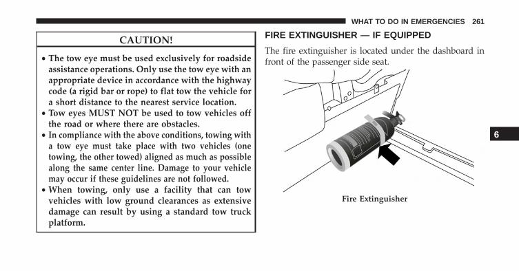
CAUTION!
• The tow eye must be used exclusively for roadsideassistance operations. Only use the tow eye with anappropriate device in accordance with the highwaycode (a rigid bar or rope) to flat tow the vehicle fora short distance to the nearest service location.
• Tow eyes MUST NOT be used to tow vehicles offthe road or where there are obstacles.
• In compliance with the above conditions, towing witha tow eye must take place with two vehicles (onetowing, the other towed) aligned as much as possiblealong the same center line. Damage to your vehiclemay occur if these guidelines are not followed.
• When towing, only use a facility that can towvehicles with low ground clearances as extensivedamage can result by using a standard tow truckplatform.
FIRE EXTINGUISHER — IF EQUIPPED
The fire extinguisher is located under the dashboard infront of the passenger side seat.
Fire Extinguisher
6
WHAT TO DO IN EMERGENCIES 261
ENHANCED ACCIDENT RESPONSE SYSTEM(EARS)
This vehicle is equipped with an Enhanced AccidentResponse System.
Please refer to “Supplemental Restraint System (SRS) —Air Bags” in “Occupant Restraints” in the Owner’sManual on the DVD for further information on theEnhanced Accident Response System (EARS) function.
EVENT DATA RECORDER (EDR)
This vehicle is equipped with an event data recorder(EDR). The main purpose of an EDR is to record, incertain crash or near crash-like situations, such as an airbag deployment or hitting a road obstacle, data that willassist in understanding how a vehicle’s systems per-formed.
Please refer to “Supplemental Restraint System (SRS) —Air Bags” in “Occupant Restraints” in the Owner’sManual on the DVD for further information on the EventData Recorder (EDR).
262 WHAT TO DO IN EMERGENCIES
MAINTAINING YOUR VEHICLE
CONTENTS� ENGINE COMPARTMENT — 1750 TURBO . . . .265
� ONBOARD DIAGNOSTIC SYSTEM — OBD II . .266
▫ Onboard Diagnostic System (OBD II)Cybersecurity . . . . . . . . . . . . . . . . . . . . . . . .266
� EMISSIONS INSPECTION ANDMAINTENANCE PROGRAMS . . . . . . . . . . . . .267
� REPLACEMENT PARTS . . . . . . . . . . . . . . . . . .269
� DEALER SERVICE . . . . . . . . . . . . . . . . . . . . . .269
� MAINTENANCE PROCEDURES . . . . . . . . . . .270
▫ Engine Oil . . . . . . . . . . . . . . . . . . . . . . . . . .271
▫ Engine Oil Filter . . . . . . . . . . . . . . . . . . . . . .273
▫ Engine Air Cleaner Filter . . . . . . . . . . . . . . . .273
▫ Engine Cover . . . . . . . . . . . . . . . . . . . . . . . .274
▫ Maintenance-Free Battery . . . . . . . . . . . . . . .274
▫ Air Conditioner Maintenance . . . . . . . . . . . . .275
▫ Body Lubrication . . . . . . . . . . . . . . . . . . . . .277
▫ Wiper Blades . . . . . . . . . . . . . . . . . . . . . . . .277
▫ Windshield Washer Nozzles . . . . . . . . . . . . . .280
▫ Adding Washer Solvent . . . . . . . . . . . . . . . . .280
▫ Exhaust System . . . . . . . . . . . . . . . . . . . . . .283
7
▫ Cooling System . . . . . . . . . . . . . . . . . . . . . .286
▫ Brake System . . . . . . . . . . . . . . . . . . . . . . . .291
▫ Alfa Twin Clutch Transmission . . . . . . . . . . .296
▫ Appearance Care And Protection FromCorrosion . . . . . . . . . . . . . . . . . . . . . . . . . . .298
� FUSES . . . . . . . . . . . . . . . . . . . . . . . . . . . . . .306
▫ Engine Compartment Fuses . . . . . . . . . . . . . .307
▫ Dashboard Fuse Box . . . . . . . . . . . . . . . . . . .310
� VEHICLE STORAGE . . . . . . . . . . . . . . . . . . . .311
� REPLACEMENT BULBS . . . . . . . . . . . . . . . . . .311
� BULB REPLACEMENT . . . . . . . . . . . . . . . . . .313
▫ Front Light Clusters . . . . . . . . . . . . . . . . . . .313
▫ Front Side Marker . . . . . . . . . . . . . . . . . . . . .318
▫ Rear Light Clusters . . . . . . . . . . . . . . . . . . . .320
▫ Direction Indicators . . . . . . . . . . . . . . . . . . .320
▫ Tail Lights/Brake Lights . . . . . . . . . . . . . . . .321
▫ Reversing Light . . . . . . . . . . . . . . . . . . . . . .321
▫ Third Brake Lights . . . . . . . . . . . . . . . . . . . .322
▫ License Plate Lights . . . . . . . . . . . . . . . . . . .323
▫ Roof Light . . . . . . . . . . . . . . . . . . . . . . . . . .324
▫ Luggage Compartment Roof Light . . . . . . . . .325
� FLUID CAPACITIES . . . . . . . . . . . . . . . . . . . .326
� FLUIDS, LUBRICANTS, AND GENUINEPARTS . . . . . . . . . . . . . . . . . . . . . . . . . . . . . .327
▫ Engine . . . . . . . . . . . . . . . . . . . . . . . . . . . . .327
▫ Chassis . . . . . . . . . . . . . . . . . . . . . . . . . . . .328
264 MAINTAINING YOUR VEHICLE
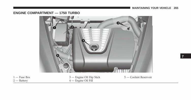
ENGINE COMPARTMENT — 1750 TURBO
1 — Fuse Box 3 — Engine Oil Dip Stick 5 — Coolant Reservoir2 — Battery 4 — Engine Oil Fill
7
MAINTAINING YOUR VEHICLE 265
ONBOARD DIAGNOSTIC SYSTEM — OBD II
Your vehicle is equipped with a sophisticated onboarddiagnostic system called OBD II. This system monitorsthe performance of the emissions, engine, and Alfa TwinClutch Transmission control systems. When these sys-tems are operating properly, your vehicle will provideexcellent performance and fuel economy, as well asengine emissions well within current government regu-lations.
If any of these systems require service, the OBD II systemwill turn on the “Malfunction Indicator Light (MIL).” Itwill also store diagnostic codes and other information toassist your service technician in making repairs. Al-though your vehicle will usually be drivable and notneed towing, see your authorized dealer for service assoon as possible.
CAUTION!
• Prolonged driving with the MIL on could causefurther damage to the emission control system. Itcould also affect fuel economy and driveability.The vehicle must be serviced before any emissionstests can be performed.
• If the MIL is flashing while the engine is running,severe catalytic converter damage and power losswill soon occur. Immediate service is required.
Onboard Diagnostic System (OBD II)Cybersecurity
Your vehicle is required to have an Onboard Diagnosticsystem (OBD II) and a connection port to allow access toinformation related to the performance of your emissionscontrols. Authorized service technicians may need to
266 MAINTAINING YOUR VEHICLE
access this information to assist with the diagnosis andservice of your vehicle and emissions system.
WARNING!
• ONLY an authorized service technician should con-nect equipment to the OBD II connection port inorder to diagnose or service your vehicle.
• If unauthorized equipment is connected to theOBD II connection port, such as a driver-behaviortracking device, it may:• Be possible that vehicle systems, including
safety related systems, could be impaired or aloss of vehicle control could occur that may resultin an accident involving serious injury or death.
• Access, or allow others to access, informationstored in your vehicle systems, including per-sonal information.
For further information, refer to “Cybersecurity” in “Un-derstanding Your Instrument Panel” in your Owner’sManual on the DVD.
EMISSIONS INSPECTION AND MAINTENANCEPROGRAMS
In some localities, it may be a legal requirement to passan inspection of your vehicle’s emissions control system.Failure to pass could prevent vehicle registration.
For states that require an Inspection and Mainte-nance (I/M), this check verifies the “MalfunctionIndicator Light (MIL)” is functioning and is not
on when the engine is running, and that the OBD IIsystem is ready for testing.
Normally, the OBD II system will be ready. The OBD IIsystem may not be ready if your vehicle was recentlyserviced, recently had a dead battery or a battery replace-ment. If the OBD II system should be determined notready for the I/M test, your vehicle may fail the test.
7
MAINTAINING YOUR VEHICLE 267
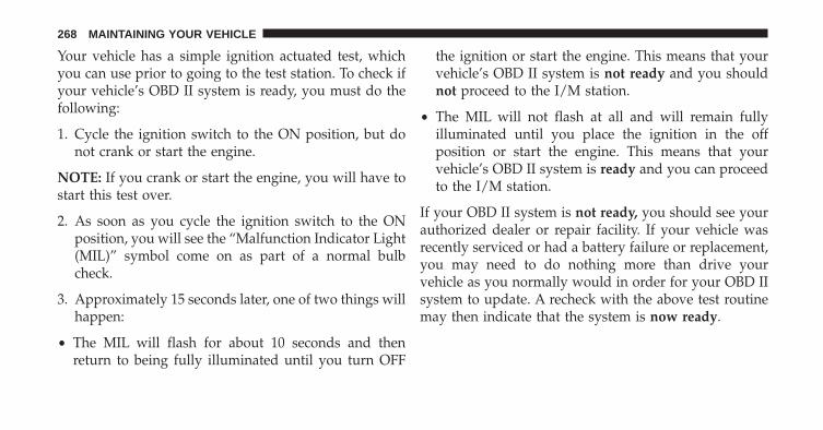
Your vehicle has a simple ignition actuated test, whichyou can use prior to going to the test station. To check ifyour vehicle’s OBD II system is ready, you must do thefollowing:
1. Cycle the ignition switch to the ON position, but donot crank or start the engine.
NOTE: If you crank or start the engine, you will have tostart this test over.
2. As soon as you cycle the ignition switch to the ONposition, you will see the “Malfunction Indicator Light(MIL)” symbol come on as part of a normal bulbcheck.
3. Approximately 15 seconds later, one of two things willhappen:
• The MIL will flash for about 10 seconds and thenreturn to being fully illuminated until you turn OFF
the ignition or start the engine. This means that yourvehicle’s OBD II system is not ready and you shouldnot proceed to the I/M station.
• The MIL will not flash at all and will remain fullyilluminated until you place the ignition in the offposition or start the engine. This means that yourvehicle’s OBD II system is ready and you can proceedto the I/M station.
If your OBD II system is not ready, you should see yourauthorized dealer or repair facility. If your vehicle wasrecently serviced or had a battery failure or replacement,you may need to do nothing more than drive yourvehicle as you normally would in order for your OBD IIsystem to update. A recheck with the above test routinemay then indicate that the system is now ready.
268 MAINTAINING YOUR VEHICLE
Regardless of whether your vehicle’s OBD II system isready or not, if the MIL is illuminated during normalvehicle operation you should have your vehicle servicedbefore going to the I/M station. The I/M station can failyour vehicle because the MIL is on with the enginerunning.
REPLACEMENT PARTS
Use of genuine parts for normal/scheduled maintenanceand repairs is highly recommended to ensure the de-signed performance. Damage or failures caused by theuse of parts which are not quality-equivalent to genuineparts for maintenance and repairs will not be covered bythe manufacturer’s warranty.
DEALER SERVICE
Your authorized dealer has the qualified service person-nel, special tools, and equipment to perform all serviceoperations in an expert manner. Service Manuals are
available which include detailed service information foryour vehicle. Refer to these Service Manuals beforeattempting any procedure yourself.
NOTE: Intentional tampering with emissions controlsystems may void your warranty and could result in civilpenalties being assessed against you.
WARNING!
You can be badly injured working on or around amotor vehicle. Only do service work for which youhave the knowledge and the proper equipment. Ifyou have any doubt about your ability to perform aservice job, take your vehicle to a competent me-chanic.
7
MAINTAINING YOUR VEHICLE 269
MAINTENANCE PROCEDURES
The pages that follow contain the required maintenanceservices determined by the engineers who designed yourvehicle.
Besides those maintenance items specified in the fixedmaintenance schedule, there are other components whichmay require servicing or replacement in the future.
CAUTION!
• Failure to properly maintain your vehicle or per-form repairs and service when necessary couldresult in more costly repairs, damage to othercomponents or negatively impact vehicle perfor-mance. Immediately have potential malfunctionsexamined by an authorized dealer or qualifiedrepair center.
(Continued)
CAUTION! (Continued)• Your vehicle has been built with improved fluids
that protect the performance and durability of yourvehicle and also allow extended maintenance inter-vals. Do not use chemical flushes in these compo-nents as the chemicals can damage your engine,transmission, or air conditioning. Such damage isnot covered by the New Vehicle Limited Warranty.If a flush is needed because of component malfunc-tion, use only the specified fluid for the flushingprocedure.
270 MAINTAINING YOUR VEHICLE
Engine Oil
Checking Oil Level
To assure proper engine lubrication, the engine oil mustbe maintained at the correct level. Check the oil level atregular intervals. The best time to check the engine oillevel is before starting the engine after it has sat over-night.
Do not check oil level when the engine is warm. Check-ing engine oil level when the engine is warm will giveyou an incorrect reading.
Checking the oil while the vehicle is on level ground, andhas sat overnight, will improve the accuracy of the oillevel readings. Maintain the oil level between the rangemarkings on the dipstick. The safe range is indicated bya crosshatch zone. Adding 1 quart of oil when the readingis at the low end of the indicated range will result in theoil level at the full end of the indicator range.
CAUTION!
Do not overfill the engine with oil. Overfilling theengine with oil will cause oil aeration, which canlead to loss of oil pressure and an increase in oiltemperature. This loss of oil pressure and increasedoil temperature could damage your engine.
Change Engine Oil
The oil change indicator system will remind you that it istime to take your vehicle in for scheduled maintenance.Refer to the “Maintenance Schedule” for further informa-tion.
NOTE: Under no circumstances should oil change inter-vals exceed 10,000 miles (16,000 km), twelve months or350 hours of engine run time, whichever comes first. The350 hours of engine run or idle time is generally only aconcern for fleet customers.
7
MAINTAINING YOUR VEHICLE 271
Engine Oil Selection
For best performance and maximum protection for tur-bocharged engines under all types of operating condi-tions, the manufacturer recommends synthetic engineoils that are API Certified and meet the requirements ofFCA Material Standard MS-12991.
Engine Oil Viscosity — 1750 Turbo Engine (SAEGrade)
SAE 5W-40 full synthetic engine oil is recommended forall operating temperatures. This engine oil improves lowtemperature starting and vehicle fuel economy.
Lubricants which do not have both the engine oil certi-fication mark and the correct SAE viscosity grade num-ber should not be used.
Materials Added To Engine Oil
The manufacturer strongly recommends against the ad-dition of any additives (other than leak detection dyes) tothe engine oil. Engine oil is an engineered product and itsperformance may be impaired by supplemental addi-tives.
Disposing Of Used Engine Oil And Oil Filters
Care should be taken in disposing of used engine oil andoil filters from your vehicle. Used oil and oil filters,indiscriminately discarded, can present a problem to theenvironment. Contact your authorized dealer, servicestation or governmental agency for advice on how andwhere used oil and oil filters can be safely discarded inyour area.
272 MAINTAINING YOUR VEHICLE
Engine Oil Filter
The engine oil filter should be replaced with a new filterat every engine oil change.
Engine Oil Filter Selection
This manufacturer’s engines have a full-flow type dispos-able oil filter. Use a filter of this type for replacement. Thequality of replacement filters varies considerably. Onlyhigh quality filters should be used to assure most efficientservice. MOPAR engine oil filters are high quality oilfilters and are recommended.
Engine Air Cleaner Filter
Refer to the “Maintenance Schedule” in the “Mainte-nance Schedules” section for the proper maintenanceintervals.
WARNING!
The air induction system (air cleaner, hoses, etc.) canprovide a measure of protection in the case of enginebackfire. Do not remove the air induction system (aircleaner, hoses, etc.) unless such removal is necessaryfor repair or maintenance. Make sure that no one isnear the engine compartment before starting thevehicle with the air induction system (air cleaner,hoses, etc.) removed. Failure to do so can result inserious personal injury.
Engine Air Cleaner Filter Selection
The quality of replacement engine air cleaner filtersvaries considerably. Only high quality filters should beused to assure most efficient service. MOPAR engine aircleaner filters are a high quality filter and are recom-mended.
7
MAINTAINING YOUR VEHICLE 273
Engine Cover
To avoid possible damage to the engine cover, pleasedisconnect each of the four mounting studs by pullingthe engine cover upward, and then lift off the completecover. Tilting the engine cover when one or more studsare still engaged will lead to premature failure of thecouplers.
To reassemble the cover back onto the engine, first makesure it is properly aligned, the oil cap is centered, and thatall four studs are lined up with their couplers. Thengently push on the four corners of the engine cover tosnap the stud back into position.
No tools are required to remove or reassemble the enginecover.
Maintenance-Free Battery
Your vehicle is equipped with a maintenance-free battery.You will never have to add water, nor is periodic main-tenance required.
WARNING!
• Battery fluid is a corrosive acid solution and canburn or even blind you. Do not allow battery fluidto contact your eyes, skin, or clothing. Do not leanover a battery when attaching clamps. If acidsplashes in eyes or on skin, flush the area imme-diately with large amounts of water. Refer to“Jump-Starting Procedures” in “What To Do InEmergencies” for further information.
• Battery gas is flammable and explosive. Keepflame or sparks away from the battery. Do not usea booster battery or any other booster source with
(Continued)
274 MAINTAINING YOUR VEHICLE
WARNING! (Continued)an output greater than 12 Volts. Do not allow cableclamps to touch each other.
• Battery posts, terminals, and related accessoriescontain lead and lead compounds. Wash handsafter handling.
• The battery in this vehicle has a vent hose thatshould not be disconnected and should only bereplaced with a battery of the same type (vented).
CAUTION!
• It is essential when replacing the cables on thebattery that the positive cable is attached to thepositive post and the negative cable is attached tothe negative post. Battery posts are marked positive(+) and negative (-) and are identified on the
(Continued)
CAUTION! (Continued)battery case. Cable clamps should be tight on theterminal posts and free of corrosion.
• If a “fast charger” is used while the battery is in thevehicle, disconnect both vehicle battery cables be-fore connecting the charger to the battery. Do notuse a “fast charger” to provide starting voltage.
Air Conditioner Maintenance
For best possible performance, your air conditionershould be checked and serviced by an authorized dealerat the start of each warm season. This service shouldinclude cleaning of the condenser fins and a performancetest. Drive belt tension should also be checked at thistime.
7
MAINTAINING YOUR VEHICLE 275
NOTE:
• Use only refrigerants and compressor lubricants ap-proved by the manufacturer for your air conditioningsystem. Some unapproved refrigerants are flammableand can explode, injuring you. Other unapprovedrefrigerants or lubricants can cause the system to fail,requiring costly repairs. Refer to Warranty InformationBook, located on the USB card, for further warrantyinformation.
• The air conditioning system contains refrigerant underhigh pressure. To avoid risk of personal injury ordamage to the system, adding refrigerant or any repairrequiring lines to be disconnected should be done byan experienced technician.
CAUTION!
Do not use chemical flushes in your air conditioningsystem as the chemicals can damage your air condi-tioning components. Such damage is not covered bythe New Vehicle Limited Warranty.
Refrigerant Recovery And Recycling HFO 1234yf
HFO 1234yf Air Conditioning Refrigerant is a hydro-fluorocarbon (HFC) that is endorsed by the Environmen-tal Protection Agency and is an ozone-saving productwith a low GWP (Global Warming Potential). However,the manufacturer recommends that air conditioning ser-vice be performed by authorized dealer or other servicefacilities using recovery and recycling equipment.
NOTE: Use only manufacturer approved A/C systemPAG compressor oil, and refrigerants.
276 MAINTAINING YOUR VEHICLE
Body Lubrication
Locks and all body pivot points, including such items asseat tracks, door hinge pivot points and rollers, liftgate,tailgate, decklid, sliding doors and hood hinges, shouldbe lubricated periodically with a lithium based grease,such as MOPAR Spray White Lube to assure quiet, easyoperation and to protect against rust and wear. Prior tothe application of any lubricant, the parts concernedshould be wiped clean to remove dust and grit; afterlubricating excess oil and grease should be removed.Particular attention should also be given to hood latchingcomponents to ensure proper function. When performingother underhood services, the hood latch, release mecha-nism and safety catch should be cleaned and lubricated.
The external lock cylinders should be lubricated twice ayear, preferably in the Fall and Spring. Apply a smallamount of a high quality lubricant, such as MOPAR LockCylinder Lubricant directly into the lock cylinder.
Wiper Blades
Clean the rubber edges of the wiper blades and thewindshield and rear window periodically with a spongeor soft cloth and a mild nonabrasive cleaner. This willremove accumulations of salt, waxes, or road film, andhelp reduce streaking and smearing.
Operation of the wipers on dry glass for long periodsmay cause deterioration of the wiper blades. Always usewasher fluid when using the wipers to remove salt or dirtfrom a dry windshield or rear window.
Avoid using the wiper blades to remove frost or ice fromthe windshield or rear window. Make sure that they arenot frozen to the glass before turning them on to avoiddamaging the blade. Keep the wiper blade out of contactwith petroleum products such as engine oil, gasoline, etc.
7
MAINTAINING YOUR VEHICLE 277
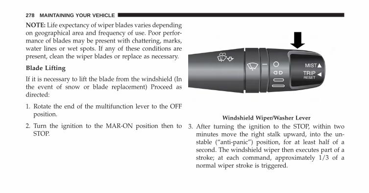
NOTE: Life expectancy of wiper blades varies dependingon geographical area and frequency of use. Poor perfor-mance of blades may be present with chattering, marks,water lines or wet spots. If any of these conditions arepresent, clean the wiper blades or replace as necessary.
Blade Lifting
If it is necessary to lift the blade from the windshield (Inthe event of snow or blade replacement) Proceed asdirected:
1. Rotate the end of the multifunction lever to the OFFposition.
2. Turn the ignition to the MAR-ON position then toSTOP.
3. After turning the ignition to the STOP, within twominutes move the right stalk upward, into the un-stable (“anti-panic”) position, for at least half of asecond. The windshield wiper then executes part of astroke; at each command, approximately 1/3 of anormal wiper stroke is triggered.
Windshield Wiper/Washer Lever
278 MAINTAINING YOUR VEHICLE
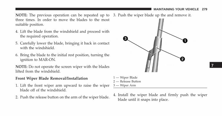
NOTE: The previous operation can be repeated up tothree times. In order to move the blades to the mostsuitable position.
4. Lift the blade from the windshield and proceed withthe required operation.
5. Carefully lower the blade, bringing it back in contactwith the windshield.
6. Bring the blade to the initial rest position, turning theignition to MAR-ON.
NOTE: Do not operate the screen wiper with the bladeslifted from the windshield.
Front Wiper Blade Removal/Installation
1. Lift the front wiper arm upward to raise the wiperblade off of the windshield.
2. Push the release button on the arm of the wiper blade.
3. Push the wiper blade up the and remove it.
4. Install the wiper blade and firmly push the wiperblade until it snaps into place.
1 — Wiper Blade2 — Release Button3 — Wiper Arm
7
MAINTAINING YOUR VEHICLE 279
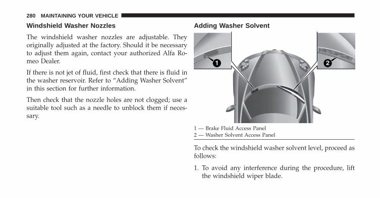
Windshield Washer Nozzles
The windshield washer nozzles are adjustable. Theyoriginally adjusted at the factory. Should it be necessaryto adjust them again, contact your authorized Alfa Ro-meo Dealer.
If there is not jet of fluid, first check that there is fluid inthe washer reservoir. Refer to “Adding Washer Solvent”in this section for further information.
Then check that the nozzle holes are not clogged; use asuitable tool such as a needle to unblock them if neces-sary.
Adding Washer Solvent
To check the windshield washer solvent level, proceed asfollows:
1. To avoid any interference during the procedure, liftthe windshield wiper blade.
1 — Brake Fluid Access Panel2 — Washer Solvent Access Panel
280 MAINTAINING YOUR VEHICLE
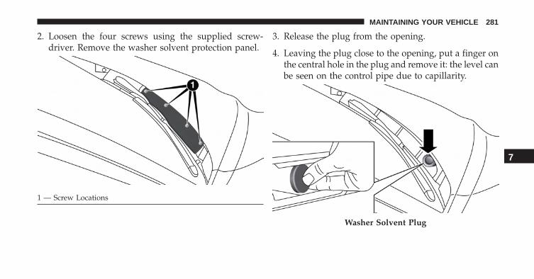
2. Loosen the four screws using the supplied screw-driver. Remove the washer solvent protection panel.
3. Release the plug from the opening.
4. Leaving the plug close to the opening, put a finger onthe central hole in the plug and remove it: the level canbe seen on the control pipe due to capillarity.
1 — Screw Locations
Washer Solvent Plug
7
MAINTAINING YOUR VEHICLE 281
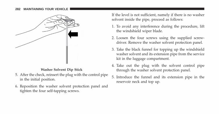
5. After the check, reinsert the plug with the control pipein the initial position.
6. Reposition the washer solvent protection panel andtighten the four self-tapping screws.
If the level is not sufficient, namely if there is no washersolvent inside the pipe, proceed as follows:
1. To avoid any interference during the procedure, liftthe windshield wiper blade.
2. Loosen the four screws using the supplied screw-driver. Remove the washer solvent protection panel.
3. Take the black funnel for topping up the windshieldwasher solvent and its extension pipe from the servicekit in the luggage compartment.
4. Take out the plug with the solvent control pipethrough the washer solvent protection panel.
5. Introduce the funnel and its extension pipe in thereservoir neck and top up.
Washer Solvent Dip Stick
282 MAINTAINING YOUR VEHICLE
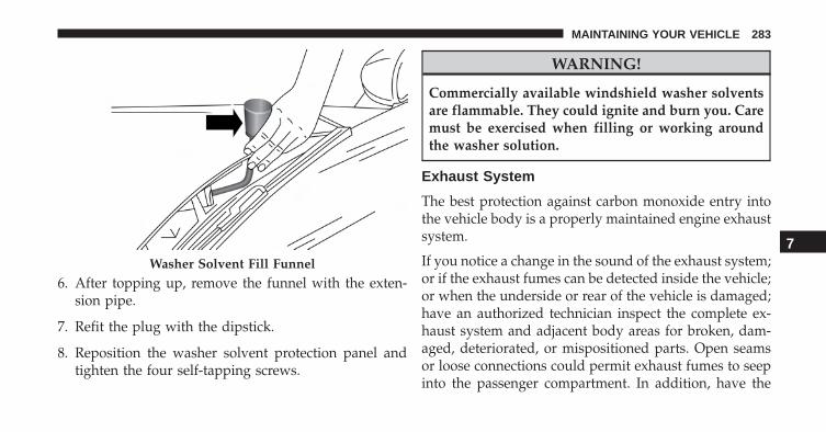
6. After topping up, remove the funnel with the exten-sion pipe.
7. Refit the plug with the dipstick.
8. Reposition the washer solvent protection panel andtighten the four self-tapping screws.
WARNING!
Commercially available windshield washer solventsare flammable. They could ignite and burn you. Caremust be exercised when filling or working aroundthe washer solution.
Exhaust System
The best protection against carbon monoxide entry intothe vehicle body is a properly maintained engine exhaustsystem.
If you notice a change in the sound of the exhaust system;or if the exhaust fumes can be detected inside the vehicle;or when the underside or rear of the vehicle is damaged;have an authorized technician inspect the complete ex-haust system and adjacent body areas for broken, dam-aged, deteriorated, or mispositioned parts. Open seamsor loose connections could permit exhaust fumes to seepinto the passenger compartment. In addition, have the
Washer Solvent Fill Funnel
7
MAINTAINING YOUR VEHICLE 283
exhaust system inspected each time the vehicle is raisedfor lubrication or oil change. Replace as required.
WARNING!
• Exhaust gases can injure or kill. They containcarbon monoxide (CO), which is colorless andodorless. Breathing it can make you unconsciousand can eventually poison you. To avoid breathingCO, refer to “Safety Tips/Exhaust Gas” in “ThingsTo Know Before Starting Your Vehicle” for furtherinformation.
• A hot exhaust system can start a fire if you parkover materials that can burn. Such materials mightbe grass or leaves coming into contact with yourexhaust system. Do not park or operate your ve-hicle in areas where your exhaust system can con-tact anything that can burn.
CAUTION!
• The catalytic converter requires the use of un-leaded fuel only. Leaded gasoline will destroy theeffectiveness of the catalyst as an emissions controldevice and may seriously reduce engine perfor-mance and cause serious damage to the engine.
• Damage to the catalytic converter can result if yourvehicle is not kept in proper operating condition.In the event of engine malfunction, particularlyinvolving engine misfire or other apparent loss ofperformance, have your vehicle serviced promptly.Continued operation of your vehicle with a severemalfunction could cause the converter to overheat,resulting in possible damage to the converter andvehicle.
284 MAINTAINING YOUR VEHICLE
Under normal operating conditions, the catalytic con-verter will not require maintenance. However, it is im-portant to keep the engine properly tuned to assureproper catalyst operation and prevent possible catalystdamage.
NOTE: Intentional tampering with emissions controlsystems can result in civil penalties being assessedagainst you.
In unusual situations involving grossly malfunctioningengine operation, a scorching odor may suggest severeand abnormal catalyst overheating. If this occurs, stopthe vehicle, turn off the engine and allow it to cool.Service, including a tune-up to manufacturer’s specifica-tions, should be obtained immediately.
To minimize the possibility of catalytic converter dam-age:
• Do not shut off the engine or interrupt the ignition,when the transmission is in gear and the vehicle is inmotion.
• Do not try to start the engine by pushing or towing thevehicle.
• Do not idle the engine with any spark plug wiresdisconnected or removed, such as when diagnostictesting, or for prolonged periods during very roughidle or malfunctioning operating conditions. 7
MAINTAINING YOUR VEHICLE 285
Cooling System
WARNING!
• When working near the radiator cooling fan, dis-connect the fan motor lead or turn the ignitionswitch to the OFF position. The fan is temperaturecontrolled and can start at any time the ignitionswitch is in the ON position.
• You or others can be badly burned by hot enginecoolant (antifreeze) or steam from your radiator. Ifyou see or hear steam coming from under the hood,do not open the hood until the radiator has hadtime to cool. Never try to open a cooling systempressure cap when the radiator is hot.
Coolant Checks
Check engine coolant (antifreeze) protection every 12months (before the onset of freezing weather, where
applicable). If the engine coolant (antifreeze) is dirty orrusty in appearance, the system should be drained,flushed and refilled with fresh engine coolant (anti-freeze). Check the front of the A/C condenser for anyaccumulation of bugs, leaves, etc. If dirty, clean by gentlyspraying water from a garden hose vertically down theface of the condenser.
Cooling System — Drain, Flush And Refill
NOTE: Some vehicles require special tools to add coolantproperly. Failure to fill these systems properly could leadto severe internal engine damage. If any coolant isneeded to be added to the system please contact yourlocal authorized dealer.
If the engine coolant (antifreeze) is dirty or containsvisible sediment, have an authorized dealer clean andflush with OAT coolant (antifreeze) (conforming toMS.90032).
286 MAINTAINING YOUR VEHICLE
Refer to the “Maintenance Schedule” for the propermaintenance intervals.
Selection Of Coolant
Refer to “Fluids, Lubricants, And Genuine Parts” in“Maintaining Your Vehicle” for further information.
CAUTION!
• Mixing of engine coolant (antifreeze) other thanspecified Organic Additive Technology (OAT) en-gine coolant (antifreeze), may result in enginedamage and may decrease corrosion protection.Organic Additive Technology (OAT) engine cool-ant is different and should not be mixed withHybrid Organic Additive Technology (HOAT) en-gine coolant (antifreeze) or any “globally compat-ible” coolant (antifreeze). If a non-OAT engine
(Continued)
CAUTION! (Continued)coolant (antifreeze) is introduced into the coolingsystem in an emergency, the cooling system willneed to be drained, flushed, and refilled with freshOAT coolant (conforming to MS.90032), by an au-thorized dealer as soon as possible.
• Do not use water alone or alcohol-based enginecoolant (antifreeze) products. Do not use additionalrust inhibitors or antirust products, as they may notbe compatible with the engine coolant and mayplug the radiator.
• This vehicle has not been designed for use withpropylene glycol-based engine coolant (antifreeze).Use of propylene glycol-based engine coolant (an-tifreeze) is not recommended.
7
MAINTAINING YOUR VEHICLE 287
Adding Coolant
Your vehicle has been built with an improved enginecoolant (OAT coolant conforming to MS.90032) that al-lows extended maintenance intervals. This engine cool-ant (antifreeze) can be used up to ten years or 150,000miles (240,000 km) before replacement. To prevent reduc-ing this extended maintenance period, it is important thatyou use the same engine coolant (OAT coolant conform-ing to MS.90032) throughout the life of your vehicle.
Please review these recommendations for using OrganicAdditive Technology (OAT) engine coolant (antifreeze)that meets the requirements of FCA Material StandardMS.90032. When adding engine coolant (antifreeze):
• We recommend using MOPAR Antifreeze/Coolant 10Year/150,000 Mile Formula OAT (Organic AdditiveTechnology) that meets the requirements of FCA Ma-terial Standard MS.90032.
• Mix a minimum solution of 50% OAT engine coolantthat meets the requirements of FCA Material StandardMS.90032 and distilled water. Use higher concentra-tions (not to exceed 70%) if temperatures below −34°F(−37°C) are anticipated. Please contact your authorizeddealer for assistance.
• Use only high purity water such as distilled or deion-ized water when mixing the water/engine coolant(antifreeze) solution. The use of lower quality waterwill reduce the amount of corrosion protection in theengine cooling system.
NOTE:
• It is the owner’s responsibility to maintain the properlevel of protection against freezing according to thetemperatures occurring in the area where the vehicle isoperated.
288 MAINTAINING YOUR VEHICLE
• Some vehicles require special tools to add coolantproperly. Failure to fill these systems properly couldlead to severe internal engine damage. If any coolant isneeded to be added to the system, please contact yourlocal authorized dealer.
• Mixing engine coolant (antifreeze) types is not recom-mended and can result in cooling system damage. IfHOAT and OAT coolant are mixed in an emergency,have a authorized dealer drain, flush, and refill withOAT coolant (conforming to MS.90032) as soon aspossible.
Cooling System Pressure Cap
The cap must be fully tightened to prevent loss of enginecoolant (antifreeze) and to ensure that engine coolant(antifreeze) will return to the radiator from the coolantrecovery tank.
The cap should be inspected and cleaned if there is anyaccumulation of foreign material on the sealing surfaces.
WARNING!
• Do not open hot engine cooling system. Never addengine coolant (antifreeze) when the engine isoverheated. Do not loosen or remove the cap to coolan overheated engine. Heat causes pressure tobuild up in the cooling system. To prevent scaldingor injury, do not remove the pressure cap while thesystem is hot or under pressure.
• Do not use a pressure cap other than the onespecified for your vehicle. Personal injury or en-gine damage may result.
7
MAINTAINING YOUR VEHICLE 289
Disposal Of Used Engine Coolant
Used ethylene glycol-based engine coolant (antifreeze) isa regulated substance requiring proper disposal. Checkwith your local authorities to determine the disposalrules for your community. To prevent ingestion by ani-mals or children, do not store ethylene glycol-basedengine coolant in open containers or allow it to remain inpuddles on the ground. If ingested by a child or pet, seekemergency assistance immediately. Clean up any groundspills immediately.
Coolant Level
The coolant expansion bottle provides a quick visualmethod for determining that the coolant level is ad-equate. With the engine off and cold, the level of theengine coolant (antifreeze) in the bottle should be be-tween the “MIN” and “MAX” marks.
As long as the engine operating temperature is satisfactory,the coolant bottle need only be checked once a month.
When additional engine coolant (antifreeze) is needed tomaintain the proper level, it should be added to thecoolant bottle. Do not overfill.
Points To Remember
NOTE: When the vehicle is stopped after a few miles/kilometers of operation, you may observe vapor comingfrom the front of the engine compartment. This is nor-mally a result of moisture from rain, snow, or highhumidity accumulating on the radiator and being vapor-ized when the thermostat opens, allowing hot enginecoolant (antifreeze) to enter the radiator.
If an examination of your engine compartment shows noevidence of radiator or hose leaks, the vehicle may besafely driven. The vapor will soon dissipate.
• Do not overfill the coolant expansion bottle.
• Check the coolant freeze point in the radiator and in
290 MAINTAINING YOUR VEHICLE
the coolant expansion bottle. If engine coolant (anti-freeze) needs to be added, the contents of the coolantexpansion bottle must also be protected against freez-ing.
• If frequent engine coolant (antifreeze) additions arerequired, the cooling system should be pressure testedfor leaks.
• Maintain engine coolant (antifreeze) concentration at aminimum of 50% OAT coolant (conforming toMS.90032) and distilled water for proper corrosionprotection of your engine which contains aluminumcomponents.
• Keep the front of the radiator clean. If your vehicle isequipped with air conditioning, keep the front of thecondenser clean.
• Do not change the thermostat for Summer or Winteroperation. If replacement is ever necessary, installONLY the correct type thermostat. Other designs may
result in unsatisfactory engine coolant (antifreeze)performance, poor gas mileage, and increased emis-sions.
Brake System
In order to assure brake system performance, all brakesystem components should be inspected periodically.Refer to the “Maintenance Schedule” for the propermaintenance intervals.
WARNING!
Riding the brakes can lead to brake failure andpossibly a collision. Driving with your foot resting orriding on the brake pedal can result in abnormallyhigh brake temperatures, excessive lining wear, andpossible brake damage. Riding the brakes may alsoreduce braking capacity in an emergency.
7
MAINTAINING YOUR VEHICLE 291
Brake Master Cylinder
The fluid level in the master cylinder should be checkedwhen performing under hood services, or immediately ifthe “Brake Warning Light” is on.
Be sure to clean the top of the master cylinder area beforeremoving the cap. If necessary, add fluid to bring thefluid level up to the requirements described on the brakefluid reservoir. Fluid level can be expected to fall as thebrake pads wear. The brake fluid level should be checkedwhen the pads are replaced. However, low fluid levelmay be caused by a leak and a checkup may be needed.
Use only manufacturer’s recommended brake fluid. Re-fer to “Fluids, Lubricants, And Genuine Parts” in “Main-taining Your Vehicle” for further information.
WARNING!
• Use only manufacturer’s recommended brakefluid. Refer to “Fluids, Lubricants, And GenuineParts” in “Maintaining Your Vehicle” for furtherinformation. Using the wrong type of brake fluidcan severely damage your brake system and/orimpair its performance. The proper type of brakefluid for your vehicle is also identified on theoriginal factory installed hydraulic master cylinderreservoir.
• To avoid contamination from foreign matter ormoisture, use only new brake fluid or fluid that hasbeen in a tightly closed container. Keep the mastercylinder reservoir cap secured at all times. Brakefluid in a open container absorbs moisture from theair resulting in a lower boiling point. This may
(Continued)
292 MAINTAINING YOUR VEHICLE
WARNING! (Continued)cause it to boil unexpectedly during hard or pro-longed braking, resulting in sudden brake failure.This could result in a collision.
• Overfilling the brake fluid reservoir can result inspilling brake fluid on hot engine parts, causingthe brake fluid to catch fire. Brake fluid can alsodamage painted and vinyl surfaces, care should betaken to avoid its contact with these surfaces.
• Do not allow petroleum-based fluid to contaminatethe brake fluid. Brake seal components could bedamaged, causing partial or complete brake failure.This could result in a collision.
CAUTION!
Use of improper brake fluids will affect overallclutch system performance. Improper brake fluidsmay damage the clutch system resulting in loss ofclutch function and the ability to shift the transmis-sion.
7
MAINTAINING YOUR VEHICLE 293
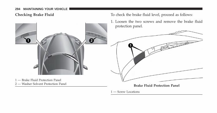
Checking Brake Fluid To check the brake fluid level, proceed as follows:
1. Loosen the two screws and remove the brake fluidprotection panel.
1 — Brake Fluid Protection Panel2 — Washer Solvent Protection Panel Brake Fluid Protection Panel
1 — Screw Locations
294 MAINTAINING YOUR VEHICLE
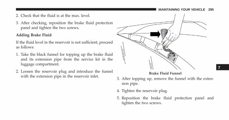
2. Check that the fluid is at the max. level.
3. After checking, reposition the brake fluid protectionpanel and tighten the two screws.
Adding Brake Fluid
If the fluid level in the reservoir is not sufficient, proceedas follows:
1. Take the black funnel for topping up the brake fluidand its extension pipe from the service kit in theluggage compartment.
2. Loosen the reservoir plug and introduce the funnelwith the extension pipe in the reservoir inlet. 3. After topping up, remove the funnel with the exten-
sion pipe.
4. Tighten the reservoir plug.
5. Reposition the brake fluid protection panel andtighten the two screws.
Brake Fluid Funnel
7
MAINTAINING YOUR VEHICLE 295
NOTE: Be very careful while removing the plug from theopening to prevent the plug from falling inside thevehicle body.
Alfa Twin Clutch Transmission
Selection Of Lubricant
It is important to use the proper transmission fluid toensure optimum transmission performance and life. Useonly the manufacturer’s specified transmission fluid.Refer to “Fluids, Lubricants, And Genuine Parts” in thissection for fluid specifications. It is important to maintainthe transmission fluid at the correct level using therecommended fluid. No chemical flushes should be usedin any transmission; only the approved lubricant shouldbe used.
CAUTION!
Using a transmission fluid other than the manufac-turer’s recommended fluid may cause deteriorationin transmission shift quality. Refer to “Fluids, Lubri-cants, and Genuine Parts” in this section for fluidspecifications.
Special Additives
The manufacturer strongly recommends against usingany special additives in the transmission.
Transmission fluid is an engineered product and itsperformance may be impaired by supplemental addi-tives. Therefore, do not add any fluid additives to thetransmission. The only exception to this policy is the useof special dyes for diagnosing fluid leaks.
296 MAINTAINING YOUR VEHICLE
CAUTION!
Do not use chemical flushes in your transmission asthe chemicals can damage your transmission compo-nents. Such damage is not covered by the NewVehicle Limited Warranty.
Fluid Level Check
The fluid level is preset at the factory and does notrequire adjustment under normal operating conditions.Routine fluid level checks are not required, therefore thetransmission has no dipstick. Your authorized dealer cancheck your transmission fluid level using special servicetools. If you notice fluid leakage or transmission malfunc-tion, visit your authorized dealer immediately to havethe transmission fluid level checked. Operating the ve-hicle with an improper fluid level can cause severetransmission damage.
CAUTION!
If a transmission fluid leak occurs, visit your autho-rized dealer immediately. Severe transmission dam-age may occur. Your authorized dealer has the propertools to adjust the fluid level accurately.
Fluid Changes
Under normal operating conditions, the fluid installed atthe factory will provide satisfactory lubrication for thelife of the vehicle. However, change the fluid if it becomescontaminated (with water, etc.), or if the transmission isdisassembled for any reason.
7
MAINTAINING YOUR VEHICLE 297
Appearance Care And Protection From Corrosion
Protection Of Body And Paint From Corrosion
Vehicle body care requirements vary according to geo-graphic locations and usage. Chemicals that make roadspassable in snow and ice and those that are sprayed ontrees and road surfaces during other seasons are highlycorrosive to the metal in your vehicle. Outside parking,which exposes your vehicle to airborne contaminants,road surfaces on which the vehicle is operated, extremehot or cold weather and other extreme conditions willhave an adverse effect on paint, metal trim, and under-body protection.
The following maintenance recommendations will enableyou to obtain maximum benefit from the corrosionresistance built into your vehicle.
What Causes Corrosion?
Corrosion is the result of deterioration or removal ofpaint and protective coatings from your vehicle.
The most common causes are:
• Road salt, dirt and moisture accumulation.
• Stone and gravel impact.
• Insects, tree sap and tar.
• Salt in the air near seacoast localities.
• Atmospheric fallout/industrial pollutants.
Washing
• Wash your vehicle regularly. Always wash your ve-hicle in the shade using MOPAR Car Wash, or a mildcar wash soap, and rinse the panels completely withclear water.
298 MAINTAINING YOUR VEHICLE
• If insects, tar, or other similar deposits have accumu-lated on your vehicle, use MOPAR Super Kleen Bugand Tar Remover to remove.
• Use a high quality cleaner wax, such as MOPARCleaner Wax to remove road film, stains and to protectyour paint finish. Take care never to scratch the paint.
• Avoid using abrasive compounds and power buffingthat may diminish the gloss or thin out the paint finish.
NOTE: Hand washing is recommended, Avoid washingwith power washers and do not use commercial car washfacilities.
CAUTION!
• Do not use abrasive or strong cleaning materialssuch as steel wool or scouring powder that willscratch metal and painted surfaces.
(Continued)
CAUTION! (Continued)• Use of power washers exceeding 1,200 psi (8 274
kPa) can result in damage or removal of paint anddecals.
• If the engine compartment is washed with an highpressure jet, keep it at a distance of at least 8 inches(20 centimeters) from filler surface.
• Do not run this vehicle through an Automatic CarWash facility as extensive damage can result due tothe vehicle’s low ground clearance.
Special Care
• If you drive on salted or dusty roads or if you drivenear the ocean, hose off the undercarriage at least oncea month.
• It is important that the drain holes in the lower edgesof the doors, rocker panels, and trunk be kept clear andopen.
7
MAINTAINING YOUR VEHICLE 299
• If you detect any stone chips or scratches in the paint,touch them up immediately. The cost of such repairs isconsidered the responsibility of the owner.
• If your vehicle is damaged due to a collision or similarcause that destroys the paint and protective coating,have your vehicle repaired as soon as possible. Thecost of such repairs is considered the responsibility ofthe owner.
• If you carry special cargo such as chemicals, fertilizers,de-icer salt, etc., be sure that such materials are wellpackaged and sealed.
• If a lot of driving is done on gravel roads, considermud or stone shields behind each wheel.
• Use MOPAR Touch Up Paint on scratches as soon aspossible. Your authorized dealer has touch up paint tomatch the color of your vehicle.
Wheel And Wheel Trim Care
All wheels and wheel trim, especially aluminum andchrome plated wheels, should be cleaned regularly usingmild (neutral Ph) soap and water to maintain their lusterand to prevent corrosion. Wash wheels with the samesoap solution recommended for the body of the vehicle.
Your wheels are susceptible to deterioration caused bysalt, sodium chloride, magnesium chloride, calcium chlo-ride, etc., and other road chemicals used to melt ice orcontrol dust on dirt roads. Use a soft cloth or sponge andmild soap to wipe away promptly. Do not use harshchemicals or a stiff brush. They can damage the wheel’sprotective coating that helps keep them from corrodingand tarnishing.
NOTE: Many aftermarket wheel cleaners contain strongacids or strong alkaline additives that can harm the wheelsurface.
300 MAINTAINING YOUR VEHICLE
CAUTION!
Avoid products or automatic car washes that useacidic solutions or strong alkaline additives or harshbrushes. These products and automatic car washesmay damage the wheel’s protective finish. Suchdamage is not covered by the New Vehicle LimitedWarranty. Only car wash soap, MOPAR WheelCleaner or equivalent is recommended.
When cleaning extremely dirty wheels including exces-sive brake dust, care must be taken in the selection of tireand wheel cleaning chemicals and equipment to preventdamage to the wheels. Mopar Wheel Treatment or MoparChrome Cleaner or their equivalent is recommended orselect a non-abrasive, non-acidic cleaner for aluminum orchrome wheels. Do not use any products on Dark Vaporor Black Satin Chrome Wheels. They will permanently
damage this finish and such damage is not covered bythe New Vehicle Limited Warranty.
CAUTION!
Do not use scouring pads, steel wool, a bristle brush,metal polishes or oven cleaner. These products maydamage the wheel’s protective finish. Such damage isnot covered by the New Vehicle Limited Warranty.Only car wash soap, MOPAR Wheel Cleaner orequivalent is recommended.
NOTE: If you intend parking or storing your vehicle foran extended period after cleaning the wheels with wheelcleaner, drive your vehicle for a few minutes before doingso. Driving the vehicle and applying the brakes whenstopping will reduce the risk of brake rotor corrosion.
7
MAINTAINING YOUR VEHICLE 301
Dark Vapor Or Black Satin Chrome Wheels
CAUTION!
If your vehicle is equipped with Dark Vapor or BlackSatin Chrome wheels DO NOT USE wheel cleaners,abrasives or polishing compounds. They will perma-nently damage this finish and such damage is notcovered by the New Vehicle Limited Warranty. USEONLY MILD SOAP AND WATER WITH A SOFTCLOTH. Used on a regular basis this is all that isrequired to maintain this finish.
Stain Repel Fabric Cleaning Procedure — IfEquipped
Stain Repel seats may be cleaned in the following man-ner:
• Remove as much of the stain as possible by blottingwith a clean, dry towel.
• Blot any remaining stain with a clean, damp towel.
• For tough stains, apply MOPAR Total Clean, or a mildsoap solution to a clean, damp cloth and remove stain.Use a fresh, damp towel to remove soap residue.
• For grease stains, apply MOPAR Multi-PurposeCleaner to a clean, damp cloth and remove stain. Usea fresh, damp towel to remove soap residue.
• Do not use any harsh solvents or any other form ofprotectants on Stain Repel products.
Interior Care
Use MOPAR Total Clean to clean fabric upholstery andcarpeting.
Use MOPAR Total Clean to clean vinyl upholstery.
MOPAR Total Clean is specifically recommended forleather upholstery.
302 MAINTAINING YOUR VEHICLE
Your leather upholstery can be best preserved by regularcleaning with a damp soft cloth. Small particles of dirtcan act as an abrasive and damage the leather upholsteryand should be removed promptly with a damp cloth.Stubborn soils can be removed easily with a soft clothand MOPAR Total Clean. Care should be taken to avoidsoaking your leather upholstery with any liquid. Pleasedo not use polishes, oils, cleaning fluids, solvents, deter-gents, or ammonia-based cleaners to clean your leatherupholstery. Application of a leather conditioner is notrequired to maintain the original condition.
WARNING!
Do not use volatile solvents for cleaning purposes.Many are potentially flammable, and if used inclosed areas they may cause respiratory harm.
CAUTION!
Direct contact of air fresheners, insect repellents,suntan lotions, or hand sanitizers to the plastic,painted, or decorated surfaces of the interior maycause permanent damage. Wipe away immediately.
CAUTION!
Damage caused by these type of products may not becovered by your New Vehicle Limited Warranty.
CAUTION!
Do not use Alcohol and Alcohol-based and/or Ketonbased cleaning products to clean leather seats, asdamage to the seat may result.
7
MAINTAINING YOUR VEHICLE 303
Cleaning Headlights
Your vehicle has plastic headlights that are lighter andless susceptible to stone breakage than glass headlights.
Plastic is not as scratch resistant as glass and thereforedifferent lens cleaning procedures must be followed.
To minimize the possibility of scratching the lenses andreducing light output, avoid wiping with a dry cloth. Toremove road dirt, wash with a mild soap solution fol-lowed by rinsing.
Do not use abrasive cleaning components, solvents, steelwool or other aggressive material to clean the lenses.
Glass Surfaces
All glass surfaces should be cleaned on a regular basiswith MOPAR, or any commercial household-type glasscleaner. Never use an abrasive type cleaner. Use caution
when cleaning the inside rear window equipped. Do notuse scrapers or other sharp instrument that may scratchthe elements.
Labels can be peeled off after soaking with warm water(if equipped), keep all objects a safe distance from thewindows.
When cleaning the rear view mirror, spray cleaner on thetowel or cloth that you are using. Do not spray cleanerdirectly on the mirror.
Instrument Panel Cover
The instrument panel cover has a low glare surface whichminimizes reflections on the windshield. Do not useprotectants or other products which may cause undesir-able reflections. Use soap and warm water to restore thelow glare surface.
304 MAINTAINING YOUR VEHICLE
Instrument Panel Bezels
CAUTION!
When installing hanging air fresheners in your ve-hicle, read the installation instructions carefully.Some air fresheners will damage the finish ofpainted or decorated parts if allowed to directlycontact any surface.
Cleaning Plastic Instrument Cluster Lenses
The lenses in front of the instruments in this vehicle aremolded in clear plastic. When cleaning the lenses, caremust be taken to avoid scratching the plastic.
1. Clean with a wet soft cloth. A mild soap solution maybe used, but do not use high alcohol content orabrasive cleaners. If soap is used, wipe clean with aclean damp cloth.
2. Dry with a soft cloth.
Seat Belt Maintenance
Do not bleach, dye or clean the belts with chemicalsolvents or abrasive cleaners. This will weaken the fabric.Sun damage can also weaken the fabric.
If the belts need cleaning, use a mild soap solution orlukewarm water. Do not remove the belts from thevehicle to wash them. Dry with a soft cloth.
Replace the belts if they appear frayed or worn or if thebuckles do not work properly.
WARNING!
A frayed or torn belt could rip apart in a collision andleave you with no protection. Inspect the belt systemperiodically, checking for cuts, frays, or loose parts.
(Continued)
7
MAINTAINING YOUR VEHICLE 305
WARNING! (Continued)Damaged parts must be replaced immediately. Do notdisassemble or modify the system. Seat belt assembliesmust be replaced after a collision if they have beendamaged (i.e., bent retractor, torn webbing, etc.).
FUSES
WARNING!
• When replacing a blown fuse, always use an appro-priate replacement fuse with the same amp rating asthe original fuse. Never replace a fuse with anotherfuse of higher amp rating. Never replace a blown fusewith metal wires or any other material. Failure to useproper fuses may result in serious personal injury, fireand/or property damage.
(Continued)
WARNING! (Continued)• Before replacing a fuse, make sure that the ignition
is off and that all the other services are switched offand/or disengaged.
• If the replaced fuse blows again, contact an autho-rized dealer.
• If a general protection fuse for safety systems (airbag system, braking system), power unit systems(engine system, gearbox system) or steering systemblows, contact an authorized dealer.
306 MAINTAINING YOUR VEHICLE
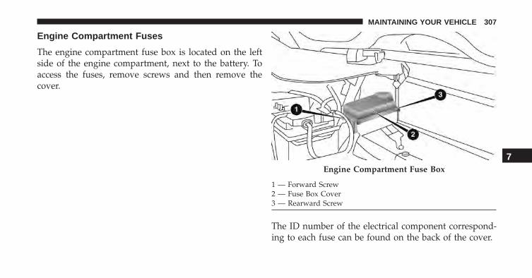
Engine Compartment Fuses
The engine compartment fuse box is located on the leftside of the engine compartment, next to the battery. Toaccess the fuses, remove screws and then remove thecover.
The ID number of the electrical component correspond-ing to each fuse can be found on the back of the cover.
Engine Compartment Fuse Box
1 — Forward Screw2 — Fuse Box Cover3 — Rearward Screw
7
MAINTAINING YOUR VEHICLE 307
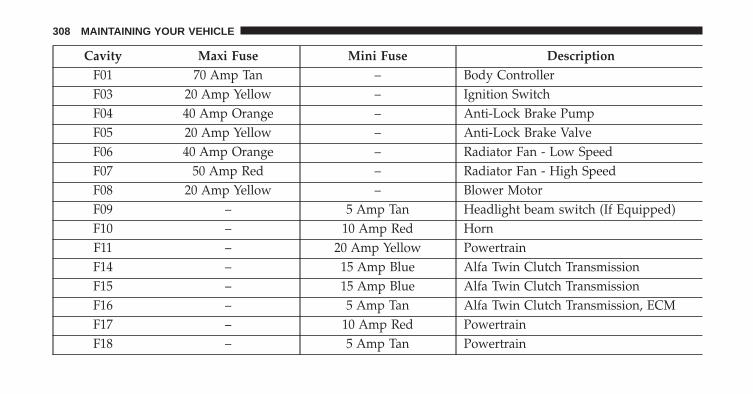
Cavity Maxi Fuse Mini Fuse DescriptionF01 70 Amp Tan – Body ControllerF03 20 Amp Yellow – Ignition SwitchF04 40 Amp Orange – Anti-Lock Brake PumpF05 20 Amp Yellow – Anti-Lock Brake ValveF06 40 Amp Orange – Radiator Fan - Low SpeedF07 50 Amp Red – Radiator Fan - High SpeedF08 20 Amp Yellow – Blower MotorF09 – 5 Amp Tan Headlight beam switch (If Equipped)F10 – 10 Amp Red HornF11 – 20 Amp Yellow PowertrainF14 – 15 Amp Blue Alfa Twin Clutch TransmissionF15 – 15 Amp Blue Alfa Twin Clutch TransmissionF16 – 5 Amp Tan Alfa Twin Clutch Transmission, ECMF17 – 10 Amp Red PowertrainF18 – 5 Amp Tan Powertrain
308 MAINTAINING YOUR VEHICLE
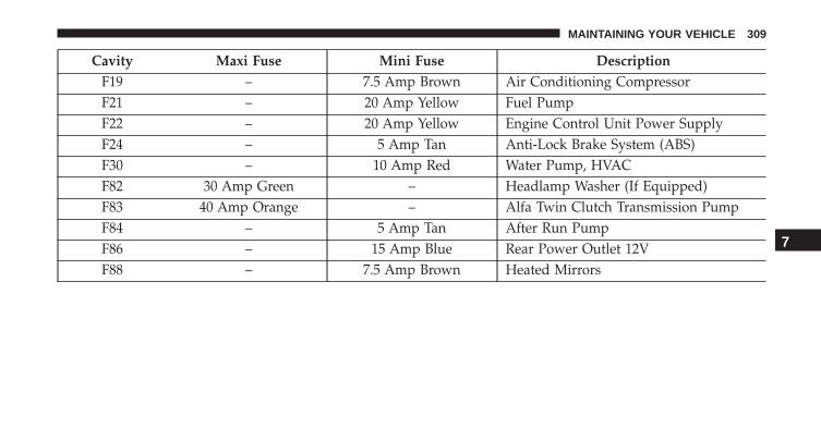
Cavity Maxi Fuse Mini Fuse DescriptionF19 – 7.5 Amp Brown Air Conditioning CompressorF21 – 20 Amp Yellow Fuel PumpF22 – 20 Amp Yellow Engine Control Unit Power SupplyF24 – 5 Amp Tan Anti-Lock Brake System (ABS)F30 – 10 Amp Red Water Pump, HVACF82 30 Amp Green – Headlamp Washer (If Equipped)F83 40 Amp Orange – Alfa Twin Clutch Transmission PumpF84 – 5 Amp Tan After Run PumpF86 – 15 Amp Blue Rear Power Outlet 12VF88 – 7.5 Amp Brown Heated Mirrors
7
MAINTAINING YOUR VEHICLE 309
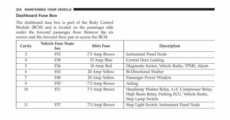
Dashboard Fuse Box
The dashboard fuse box is part of the Body ControlModule (BCM) and is located on the passenger sideunder the forward passenger floor. Remove the sixscrews and the forward floor pan to access the BCM.
CavityVehicle Fuse Num-
berMini Fuse Description
3 F53 7.5 Amp Brown Instrument Panel Node4 F38 15 Amp Blue Central Door Locking5 F36 10 Amp Red Diagnostic Socket, Vehicle Radio, TPMS, Alarm6 F43 20 Amp Yellow Bi-Directional Washer7 F48 20 Amp Yellow Passenger Power Window9 F50 7.5 Amp Brown Airbag
10 F51 7.5 Amp Brown Headlamp Washer Relay, A/C Compressor Relay,High Beam Relay, Parking ECU, Vehicle Radio,Stop Lamp Switch
11 F37 7.5 Amp Brown Stop Light Switch, Instrument Panel Node
310 MAINTAINING YOUR VEHICLE
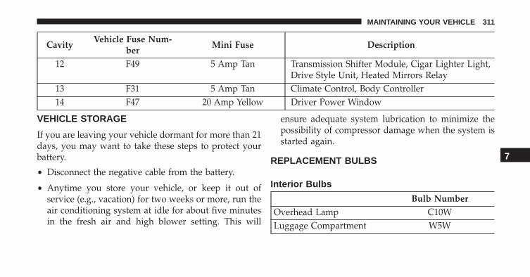
CavityVehicle Fuse Num-
berMini Fuse Description
12 F49 5 Amp Tan Transmission Shifter Module, Cigar Lighter Light,Drive Style Unit, Heated Mirrors Relay
13 F31 5 Amp Tan Climate Control, Body Controller14 F47 20 Amp Yellow Driver Power Window
VEHICLE STORAGE
If you are leaving your vehicle dormant for more than 21days, you may want to take these steps to protect yourbattery.
• Disconnect the negative cable from the battery.
• Anytime you store your vehicle, or keep it out ofservice (e.g., vacation) for two weeks or more, run theair conditioning system at idle for about five minutesin the fresh air and high blower setting. This will
ensure adequate system lubrication to minimize thepossibility of compressor damage when the system isstarted again.
REPLACEMENT BULBS
Interior Bulbs
Bulb NumberOverhead Lamp C10WLuggage Compartment W5W
7
MAINTAINING YOUR VEHICLE 311
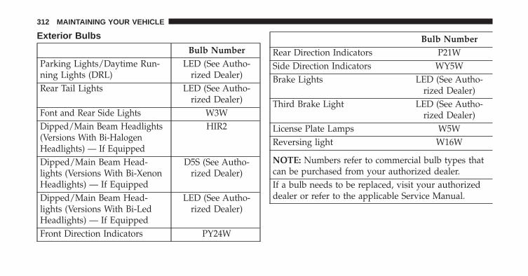
Exterior Bulbs
Bulb NumberParking Lights/Daytime Run-ning Lights (DRL)
LED (See Autho-rized Dealer)
Rear Tail Lights LED (See Autho-rized Dealer)
Font and Rear Side Lights W3WDipped/Main Beam Headlights(Versions With Bi-HalogenHeadlights) — If Equipped
HIR2
Dipped/Main Beam Head-lights (Versions With Bi-XenonHeadlights) — If Equipped
D5S (See Autho-rized Dealer)
Dipped/Main Beam Head-lights (Versions With Bi-LedHeadlights) — If Equipped
LED (See Autho-rized Dealer)
Front Direction Indicators PY24W
Bulb NumberRear Direction Indicators P21WSide Direction Indicators WY5WBrake Lights LED (See Autho-
rized Dealer)Third Brake Light LED (See Autho-
rized Dealer)License Plate Lamps W5WReversing light W16W
NOTE: Numbers refer to commercial bulb types thatcan be purchased from your authorized dealer.If a bulb needs to be replaced, visit your authorizeddealer or refer to the applicable Service Manual.
312 MAINTAINING YOUR VEHICLE
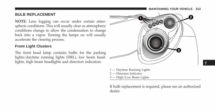
BULB REPLACEMENT
NOTE: Lens fogging can occur under certain atmo-spheric conditions. This will usually clear as atmosphericconditions change to allow the condensation to changeback into a vapor. Turning the lamps on will usuallyaccelerate the clearing process.
Front Light Clusters
The front head lamp contains bulbs for the parkinglights/daytime running lights (DRL), low beam head-lights, high beam headlights and direction indicators.
If bulb replacement is required, please see an authorizeddealer.
1 — Daytime Running Lights2 — Direction Indicator3 — High/Low Beam Lights
7
MAINTAINING YOUR VEHICLE 313
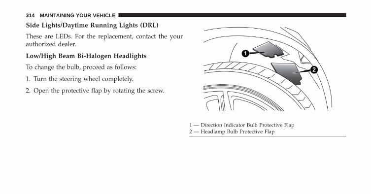
Side Lights/Daytime Running Lights (DRL)
These are LEDs. For the replacement, contact the yourauthorized dealer.
Low/High Beam Bi-Halogen Headlights
To change the bulb, proceed as follows:
1. Turn the steering wheel completely.
2. Open the protective flap by rotating the screw.
1 — Direction Indicator Bulb Protective Flap2 — Headlamp Bulb Protective Flap
314 MAINTAINING YOUR VEHICLE
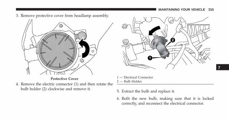
3. Remove protective cover from headlamp assembly.
4. Remove the electric connector (1) and then rotate thebulb holder (2) clockwise and remove it. 5. Extract the bulb and replace it.
6. Refit the new bulb, making sure that it is lockedcorrectly, and reconnect the electrical connector.
Protective Cover 1 — Electrical Connector2 — Bulb Holder
7
MAINTAINING YOUR VEHICLE 315
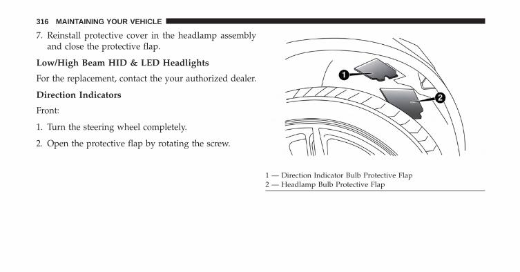
7. Reinstall protective cover in the headlamp assemblyand close the protective flap.
Low/High Beam HID & LED Headlights
For the replacement, contact the your authorized dealer.
Direction Indicators
Front:
1. Turn the steering wheel completely.
2. Open the protective flap by rotating the screw.
1 — Direction Indicator Bulb Protective Flap2 — Headlamp Bulb Protective Flap
316 MAINTAINING YOUR VEHICLE
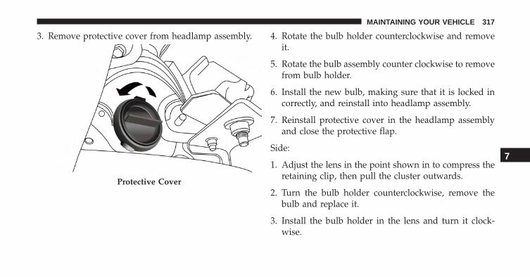
3. Remove protective cover from headlamp assembly. 4. Rotate the bulb holder counterclockwise and removeit.
5. Rotate the bulb assembly counter clockwise to removefrom bulb holder.
6. Install the new bulb, making sure that it is locked incorrectly, and reinstall into headlamp assembly.
7. Reinstall protective cover in the headlamp assemblyand close the protective flap.
Side:
1. Adjust the lens in the point shown in to compress theretaining clip, then pull the cluster outwards.
2. Turn the bulb holder counterclockwise, remove thebulb and replace it.
3. Install the bulb holder in the lens and turn it clock-wise.
Protective Cover
7
MAINTAINING YOUR VEHICLE 317
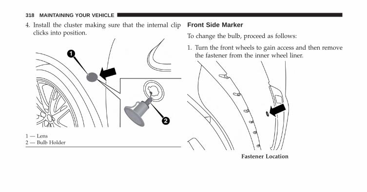
4. Install the cluster making sure that the internal clipclicks into position.
Front Side Marker
To change the bulb, proceed as follows:
1. Turn the front wheels to gain access and then removethe fastener from the inner wheel liner.
1 — Lens2 — Bulb Holder
Fastener Location
318 MAINTAINING YOUR VEHICLE
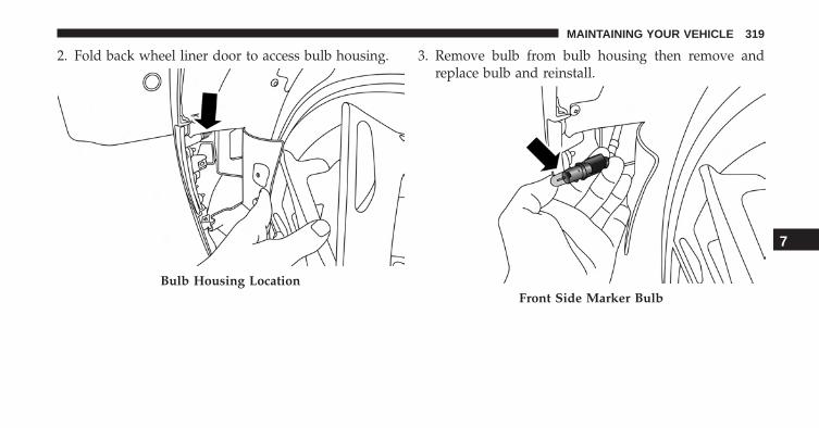
2. Fold back wheel liner door to access bulb housing. 3. Remove bulb from bulb housing then remove andreplace bulb and reinstall.
Bulb Housing LocationFront Side Marker Bulb
7
MAINTAINING YOUR VEHICLE 319
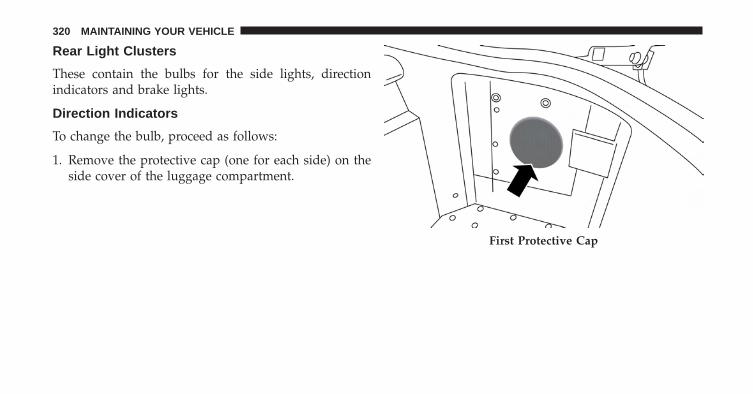
Rear Light Clusters
These contain the bulbs for the side lights, directionindicators and brake lights.
Direction Indicators
To change the bulb, proceed as follows:
1. Remove the protective cap (one for each side) on theside cover of the luggage compartment.
First Protective Cap
320 MAINTAINING YOUR VEHICLE
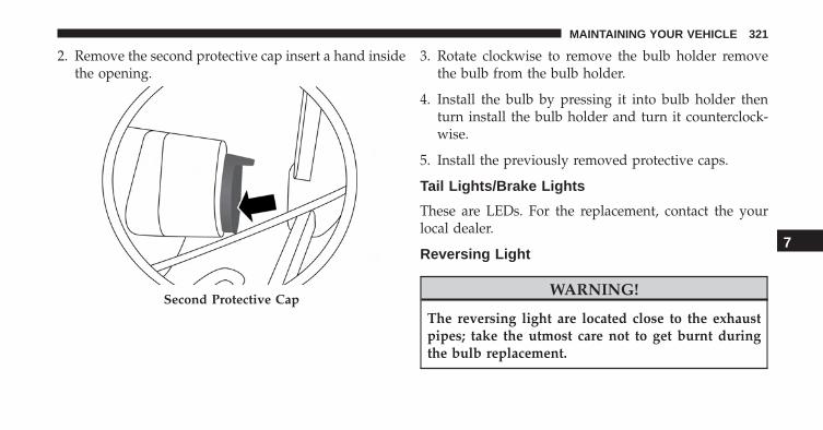
2. Remove the second protective cap insert a hand insidethe opening.
3. Rotate clockwise to remove the bulb holder removethe bulb from the bulb holder.
4. Install the bulb by pressing it into bulb holder thenturn install the bulb holder and turn it counterclock-wise.
5. Install the previously removed protective caps.
Tail Lights/Brake Lights
These are LEDs. For the replacement, contact the yourlocal dealer.
Reversing Light
WARNING!
The reversing light are located close to the exhaustpipes; take the utmost care not to get burnt duringthe bulb replacement.
Second Protective Cap
7
MAINTAINING YOUR VEHICLE 321
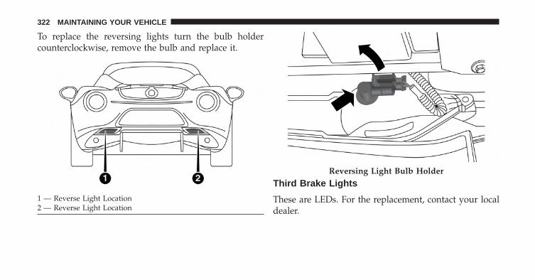
To replace the reversing lights turn the bulb holdercounterclockwise, remove the bulb and replace it.
Third Brake Lights
These are LEDs. For the replacement, contact your localdealer.
1 — Reverse Light Location2 — Reverse Light Location
Reversing Light Bulb Holder
322 MAINTAINING YOUR VEHICLE
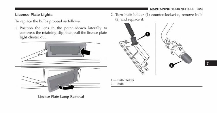
License Plate Lights
To replace the bulbs proceed as follows:
1. Position the lens in the point shown laterally tocompress the retaining clip, then pull the license platelight cluster out.
2. Turn bulb holder (1) counterclockwise, remove bulb(2) and replace it.
License Plate Lamp Removal
1 — Bulb Holder2 — Bulb
7
MAINTAINING YOUR VEHICLE 323
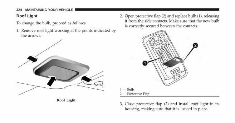
Roof Light
To change the bulb, proceed as follows:
1. Remove roof light working at the points indicated bythe arrows.
2. Open protective flap (2) and replace bulb (1), releasingit from the side contacts. Make sure that the new bulbis correctly secured between the contacts.
3. Close protective flap (2) and install roof light in itshousing, making sure that it is locked in place.
Roof Light
1 — Bulb2 — Protective Flap
324 MAINTAINING YOUR VEHICLE
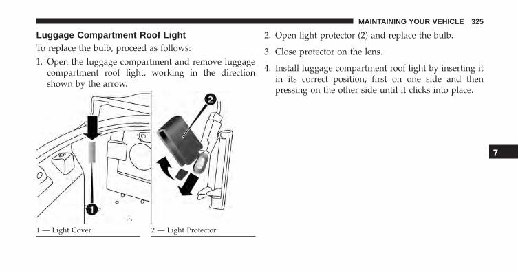
Luggage Compartment Roof LightTo replace the bulb, proceed as follows:1. Open the luggage compartment and remove luggage
compartment roof light, working in the directionshown by the arrow.
2. Open light protector (2) and replace the bulb.
3. Close protector on the lens.
4. Install luggage compartment roof light by inserting itin its correct position, first on one side and thenpressing on the other side until it clicks into place.
1 — Light Cover 2 — Light Protector
7
MAINTAINING YOUR VEHICLE 325
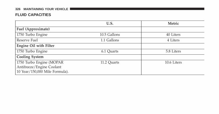
FLUID CAPACITIES
U.S. MetricFuel (Approximate)1750 Turbo Engine 10.5 Gallons 40 LitersReserve Fuel 1.1 Gallons 4 LitersEngine Oil with Filter1750 Turbo Engine 6.1 Quarts 5.8 LitersCooling System1750 Turbo Engine (MOPARAntifreeze/Engine Coolant10 Year/150,000 Mile Formula).
11.2 Quarts 10.6 Liters
326 MAINTAINING YOUR VEHICLE
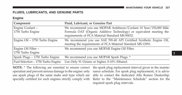
FLUIDS, LUBRICANTS, AND GENUINE PARTS
Engine
Component Fluid, Lubricant, or Genuine PartEngine Coolant –1750 Turbo Engine
We recommend you use MOPAR Antifreeze/Coolant 10 Year/150,000 MileFormula OAT (Organic Additive Technology) or equivalent meeting therequirements of FCA Material Standard MS.90032.
Engine Oil – 1750 Turbo Engine We recommend you use SAE 5W-40 API Certified Synthetic Engine Oil,meeting the requirements of FCA Material Standard MS-12991.
Engine Oil Filter –1750 Turbo Engine
We recommend you use MOPAR Engine Oil Filter.
Spark Plugs – 1750 Turbo Engine We recommend you use MOPAR Spark Plugs. *Fuel Selection – 1750 Turbo Engine Use Only 91 Octane or higher, 0-10% Ethanol.
NOTE: * The following are essential to ensure correctoperation and prevent serious damage to the engine: onlyuse spark plugs of the same make and type which arespecially certified for such engines strictly comply with
the spark plug replacement interval given in the mainte-nance schedule. For spark plug replacement, it is advis-able to contact the dedicated Alfa Romeo Dealership.Refer to the “Maintenance Schedule” section for therequired spark plug intervals.
7
MAINTAINING YOUR VEHICLE 327
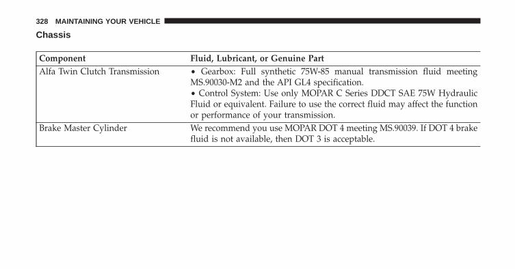
Chassis
Component Fluid, Lubricant, or Genuine PartAlfa Twin Clutch Transmission • Gearbox: Full synthetic 75W-85 manual transmission fluid meeting
MS.90030-M2 and the API GL4 specification.• Control System: Use only MOPAR C Series DDCT SAE 75W HydraulicFluid or equivalent. Failure to use the correct fluid may affect the functionor performance of your transmission.
Brake Master Cylinder We recommend you use MOPAR DOT 4 meeting MS.90039. If DOT 4 brakefluid is not available, then DOT 3 is acceptable.
328 MAINTAINING YOUR VEHICLE
MAINTENANCE SCHEDULES
CONTENTS� MAINTENANCE SCHEDULE . . . . . . . . . . . . .330 ▫ Maintenance Chart . . . . . . . . . . . . . . . . . . . .333
8
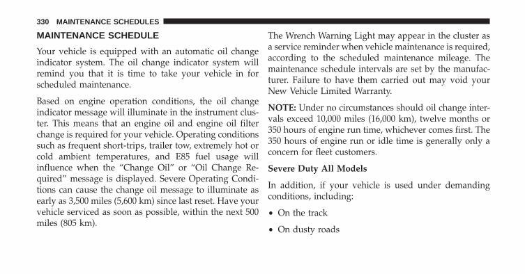
MAINTENANCE SCHEDULE
Your vehicle is equipped with an automatic oil changeindicator system. The oil change indicator system willremind you that it is time to take your vehicle in forscheduled maintenance.
Based on engine operation conditions, the oil changeindicator message will illuminate in the instrument clus-ter. This means that an engine oil and engine oil filterchange is required for your vehicle. Operating conditionssuch as frequent short-trips, trailer tow, extremely hot orcold ambient temperatures, and E85 fuel usage willinfluence when the “Change Oil” or “Oil Change Re-quired” message is displayed. Severe Operating Condi-tions can cause the change oil message to illuminate asearly as 3,500 miles (5,600 km) since last reset. Have yourvehicle serviced as soon as possible, within the next 500miles (805 km).
The Wrench Warning Light may appear in the cluster asa service reminder when vehicle maintenance is required,according to the scheduled maintenance mileage. Themaintenance schedule intervals are set by the manufac-turer. Failure to have them carried out may void yourNew Vehicle Limited Warranty.
NOTE: Under no circumstances should oil change inter-vals exceed 10,000 miles (16,000 km), twelve months or350 hours of engine run time, whichever comes first. The350 hours of engine run or idle time is generally only aconcern for fleet customers.
Severe Duty All Models
In addition, if your vehicle is used under demandingconditions, including:
• On the track
• On dusty roads
330 MAINTENANCE SCHEDULES
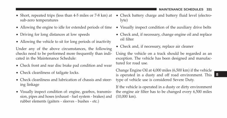
• Short, repeated trips (less than 4-5 miles or 7-8 km) atsub-zero temperatures
• Allowing the engine to idle for extended periods of time
• Driving for long distances at low speeds
• Allowing the vehicle to sit for long periods of inactivity
Under any of the above circumstances, the followingchecks need to be performed more frequently than indi-cated in the Maintenance Schedule:
• Check front and rear disc brake pad condition and wear
• Check cleanliness of tailgate locks.
• Check cleanliness and lubrication of chassis and steer-ing linkage
• Visually inspect condition of: engine, gearbox, transmis-sion, pipes and hoses (exhaust - fuel system - brakes) andrubber elements (gaiters - sleeves - bushes - etc.)
• Check battery charge and battery fluid level (electro-lyte)
• Visually inspect condition of the auxiliary drive belts
• Check and, if necessary, change engine oil and replaceoil filter
• Check and, if necessary, replace air cleaner
Using the vehicle on a track should be regarded as anexception. The vehicle has been designed and manufac-tured for road use.
Change Engine Oil at 4,000 miles (6,500 km) if the vehicleis operated in a dusty and off road environment. Thistype of vehicle use is considered Severe Duty.
If the vehicle is operated in a dusty or dirty environmentthe engine air filter has to be changed every 6,500 miles(10,000 km).
8
MAINTENANCE SCHEDULES 331
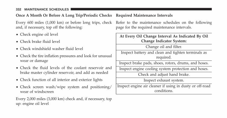
Once A Month Or Before A Long Trip/Periodic Checks
Every 600 miles (1,000 km) or before long trips, checkand, if necessary, top off the following:
• Check engine oil level
• Check brake fluid level
• Check windshield washer fluid level
• Check the tire inflation pressures and look for unusualwear or damage
• Check the fluid levels of the coolant reservoir andbrake master cylinder reservoir, and add as needed
• Check function of all interior and exterior lights
• Check screen wash/wipe system and positioning/wear of windscreen
Every 2,000 miles (3,000 km) check and, if necessary, topup: engine oil level
Required Maintenance Intervals
Refer to the maintenance schedules on the followingpage for the required maintenance intervals.
At Every Oil Change Interval As Indicated By OilChange Indicator System:
Change oil and filter.Inspect battery and clean and tighten terminals as
required.Inspect brake pads, shoes, rotors, drums, and hoses.Inspect engine cooling system protection and hoses.
Check and adjust hand brake.Inspect exhaust system.
Inspect engine air cleaner if using in dusty or off-roadconditions.
332 MAINTENANCE SCHEDULES
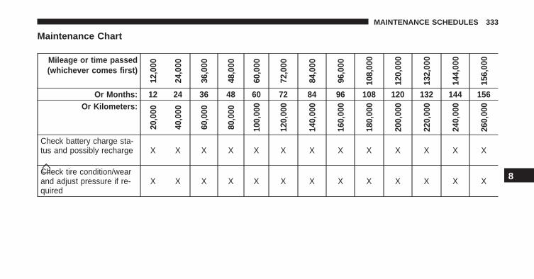
Maintenance Chart
Mileage or time passed(whichever comes first)
12,0
00
24,0
00
36,0
00
48,0
00
60,0
00
72,0
00
84,0
00
96,0
00
108,
000
120,
000
132,
000
144,
000
156,
000
Or Months: 12 24 36 48 60 72 84 96 108 120 132 144 156Or Kilometers:
20,0
00
40,0
00
60,0
00
80,0
00
100,
000
120,
000
140,
000
160,
000
180,
000
200,
000
220,
000
240,
000
260,
000
Check battery charge sta-tus and possibly recharge X X X X X X X X X X X X X
Check tire condition/wearand adjust pressure if re-quired
X X X X X X X X X X X X X 8
MAINTENANCE SCHEDULES 333

Mileage or time passed(whichever comes first)
12,0
00
24,0
00
36,0
00
48,0
00
60,0
00
72,0
00
84,0
00
96,0
00
108,
000
120,
000
132,
000
144,
000
156,
000
Or Months: 12 24 36 48 60 72 84 96 108 120 132 144 156Or Kilometers:
20,0
00
40,0
00
60,0
00
80,0
00
100,
000
120,
000
140,
000
160,
000
180,
000
200,
000
220,
000
240,
000
260,
000
Check lighting system op-eration (headlights, direc-tion indicators, hazardlights, passenger compart-ment lights, boot lights,instrument panel warninglights, etc.)
X X X X X X X X X X X X X
Check vehicle fasteners X X X X X X XCheck mechanical compo-nents fasteners X X X X X X X X X X X X X
Check windscreen wiper/washer operation, adjustnozzles
X X X X X X X X X X X X X
334 MAINTENANCE SCHEDULES
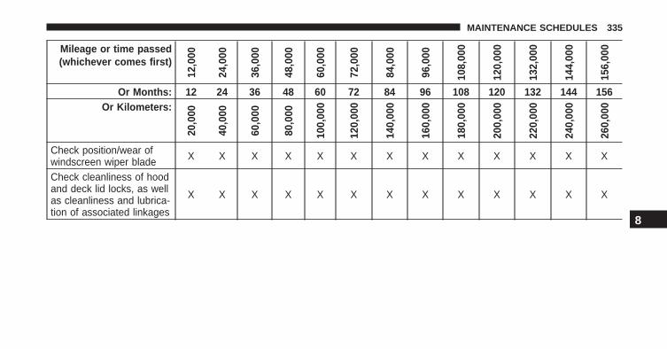
Mileage or time passed(whichever comes first)
12,0
00
24,0
00
36,0
00
48,0
00
60,0
00
72,0
00
84,0
00
96,0
00
108,
000
120,
000
132,
000
144,
000
156,
000
Or Months: 12 24 36 48 60 72 84 96 108 120 132 144 156Or Kilometers:
20,0
00
40,0
00
60,0
00
80,0
00
100,
000
120,
000
140,
000
160,
000
180,
000
200,
000
220,
000
240,
000
260,
000
Check position/wear ofwindscreen wiper blade X X X X X X X X X X X X X
Check cleanliness of hoodand deck lid locks, as wellas cleanliness and lubrica-tion of associated linkages
X X X X X X X X X X X X X
8
MAINTENANCE SCHEDULES 335
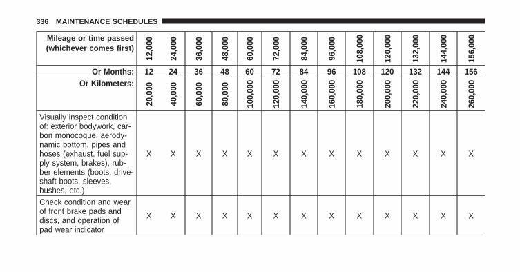
Mileage or time passed(whichever comes first)
12,0
00
24,0
00
36,0
00
48,0
00
60,0
00
72,0
00
84,0
00
96,0
00
108,
000
120,
000
132,
000
144,
000
156,
000
Or Months: 12 24 36 48 60 72 84 96 108 120 132 144 156Or Kilometers:
20,0
00
40,0
00
60,0
00
80,0
00
100,
000
120,
000
140,
000
160,
000
180,
000
200,
000
220,
000
240,
000
260,
000
Visually inspect conditionof: exterior bodywork, car-bon monocoque, aerody-namic bottom, pipes andhoses (exhaust, fuel sup-ply system, brakes), rub-ber elements (boots, drive-shaft boots, sleeves,bushes, etc.)
X X X X X X X X X X X X X
Check condition and wearof front brake pads anddiscs, and operation ofpad wear indicator
X X X X X X X X X X X X X
336 MAINTENANCE SCHEDULES
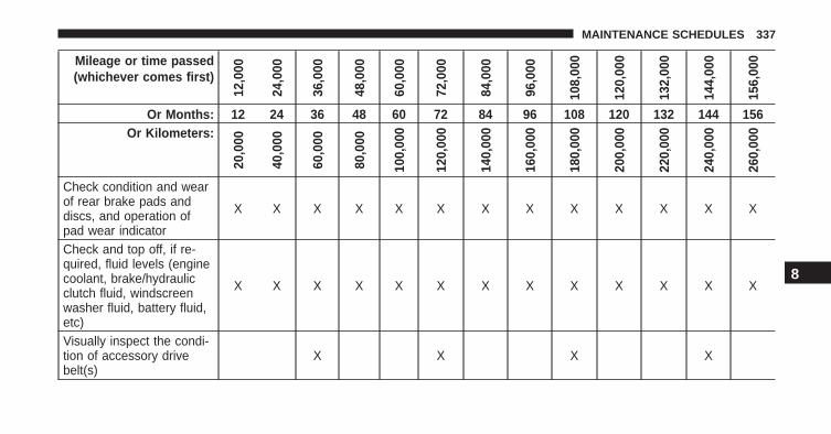
Mileage or time passed(whichever comes first)
12,0
00
24,0
00
36,0
00
48,0
00
60,0
00
72,0
00
84,0
00
96,0
00
108,
000
120,
000
132,
000
144,
000
156,
000
Or Months: 12 24 36 48 60 72 84 96 108 120 132 144 156Or Kilometers:
20,0
00
40,0
00
60,0
00
80,0
00
100,
000
120,
000
140,
000
160,
000
180,
000
200,
000
220,
000
240,
000
260,
000
Check condition and wearof rear brake pads anddiscs, and operation ofpad wear indicator
X X X X X X X X X X X X X
Check and top off, if re-quired, fluid levels (enginecoolant, brake/hydraulicclutch fluid, windscreenwasher fluid, battery fluid,etc)
X X X X X X X X X X X X X
Visually inspect the condi-tion of accessory drivebelt(s)
X X X X
8
MAINTENANCE SCHEDULES 337
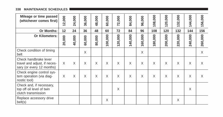
Mileage or time passed(whichever comes first)
12,0
00
24,0
00
36,0
00
48,0
00
60,0
00
72,0
00
84,0
00
96,0
00
108,
000
120,
000
132,
000
144,
000
156,
000
Or Months: 12 24 36 48 60 72 84 96 108 120 132 144 156Or Kilometers:
20,0
00
40,0
00
60,0
00
80,0
00
100,
000
120,
000
140,
000
160,
000
180,
000
200,
000
220,
000
240,
000
260,
000
Check condition of timingbelt X X X
Check handbrake levertravel and adjust, if neces-sary (or every 12 months)
X X X X X X X X X X X X X
Check engine control sys-tem operation (via diag-nostic tool)
X X X X X X X X X X X X X
Check and, if necessary,top off oil level of twinclutch transmission
X X
Replace accessory drivebelt(s) X X
338 MAINTENANCE SCHEDULES
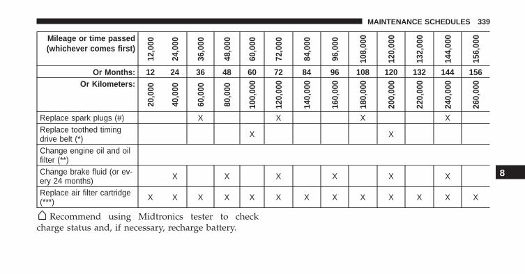
Mileage or time passed(whichever comes first)
12,0
00
24,0
00
36,0
00
48,0
00
60,0
00
72,0
00
84,0
00
96,0
00
108,
000
120,
000
132,
000
144,
000
156,
000
Or Months: 12 24 36 48 60 72 84 96 108 120 132 144 156Or Kilometers:
20,0
00
40,0
00
60,0
00
80,0
00
100,
000
120,
000
140,
000
160,
000
180,
000
200,
000
220,
000
240,
000
260,
000
Replace spark plugs (#) X X X XReplace toothed timingdrive belt (*) X X
Change engine oil and oilfilter (**)Change brake fluid (or ev-ery 24 months) X X X X X X
Replace air filter cartridge(***) X X X X X X X X X X X X X
Recommend using Midtronics tester to checkcharge status and, if necessary, recharge battery.
8
MAINTENANCE SCHEDULES 339
(#) The spark plug change interval is mileage based only,yearly intervals do not apply. The following are essentialto ensure correct operation and prevent serious damageto the engine:
• Only use spark plugs of the same make and typewhich are specially certified for such engines (refer to“Fluids, Lubricants and Genuine Parts” in “Maintain-ing Your Vehicle” for further information).
• Strictly comply with the spark plug replacement inter-val given in the maintenance schedule for spark plugreplacement.
• Contact your Alfa Romeo Dealer if you have questions.
(*) Regardless of the distance covered, the timing beltmust be changed every 4 years for particularly demand-ing use (cold climates, city driving, long periods ofidling) or at least every 5 years.
(**) The actual interval for changing the oil and replacingthe engine oil filter depends on the vehicle usage condi-tions and is signalled by the warning light or message (ifpresent) on the instrument panel or every 12 months.
(***) If the vehicle is operated in a dusty or dirtyenvironment the engine air filter has to be changed every6,500 miles (10,000 km).
WARNING!
• You can be badly injured working on or around amotor vehicle. Do only service work for which youhave the knowledge and the right equipment. If youhave any doubt about your ability to perform a servicejob, take your vehicle to a competent mechanic.
• Failure to properly inspect and maintain your ve-hicle could result in a component malfunction andeffect vehicle handling and performance. Thiscould cause an accident.
340 MAINTENANCE SCHEDULES
IF YOU NEED CONSUMER ASSISTANCE
CONTENTS� SUGGESTIONS FOR OBTAINING SERVICE
FOR YOUR VEHICLE . . . . . . . . . . . . . . . . . . .342
▫ Prepare For The Appointment. . . . . . . . . . . . .342
▫ Prepare A List . . . . . . . . . . . . . . . . . . . . . . . .342
▫ Be Reasonable With Requests . . . . . . . . . . . . .342
� IF YOU NEED ASSISTANCE . . . . . . . . . . . . . .342
▫ Alfa Customer Center . . . . . . . . . . . . . . . . . .343
▫ Alfa Customer Center (Canada) . . . . . . . . . . .343
▫ Customer Assistance For The Hearing OrSpeech Impaired (TDD/TTY) . . . . . . . . . . . . .343
▫ Service Contract . . . . . . . . . . . . . . . . . . . . . .344
� WARRANTY INFORMATION . . . . . . . . . . . . .345
� REPORTING SAFETY DEFECTS . . . . . . . . . . . .345
▫ In The 50 United States And Washington, D.C. . . .345
▫ In Canada . . . . . . . . . . . . . . . . . . . . . . . . . . .346
� PUBLICATION ORDER FORMS . . . . . . . . . . . .346
� DEPARTMENT OF TRANSPORTATIONUNIFORM TIRE QUALITY GRADES . . . . . . . .347
▫ Treadwear. . . . . . . . . . . . . . . . . . . . . . . . . . .347
▫ Traction Grades . . . . . . . . . . . . . . . . . . . . . . .348
▫ Temperature Grades. . . . . . . . . . . . . . . . . . . .348
9
SUGGESTIONS FOR OBTAINING SERVICE FORYOUR VEHICLE
Prepare For The Appointment
If you are having warranty work done, be sure to havethe right papers with you. Take your warranty folder. Allwork to be performed may not be covered by thewarranty. Discuss additional charges with the servicemanager. Keep a maintenance log of your vehicle’sservice history. This can often provide a clue to thecurrent problem.
Prepare A List
Make a written list of your vehicle’s problems or thespecific work you want done. If you’ve had an accidentor work done that is not on your maintenance log, let theservice advisor know.
Be Reasonable With Requests
If you list a number of items and you must have yourvehicle by the end of the day, discuss the situation withthe service advisor and list the items in order of priority.At many authorized dealers, you may obtain a rentalvehicle at a minimal daily charge. If you need a rental, itis advisable to make these arrangements when you callfor an appointment.
IF YOU NEED ASSISTANCE
The manufacturer and its authorized dealer are vitallyinterested in your satisfaction. We want you to be happywith our products and services.
Warranty service must be done by an authorized dealer.We strongly recommend that you take the vehicle to anauthorized dealer. They know your vehicle the best, andare most concerned that you get prompt and high qualityservice. The manufacturer’s authorized dealer have the
342 IF YOU NEED CONSUMER ASSISTANCE
facilities, factory-trained technicians, special tools, andthe latest information to ensure the vehicle is fixedcorrectly and in a timely manner.
This is why you should always talk to an authorizeddealer service manager first. Most matters can be re-solved with this process.
• If for some reason you are still not satisfied, talk to thegeneral manager or owner of the authorized dealer.They want to know if you need assistance.
• If an authorized dealer is unable to resolve the con-cern, you may contact the manufacturer’s customercenter.
Any communication to the manufacturer’s customer cen-ter should include the following information:
• Owner’s name and address
• Owner’s telephone number (home and office)
• Authorized dealer name
• Vehicle Identification Number (VIN)
• Vehicle delivery date and mileage
Alfa Customer Center
P.O. Box 21–8004 Auburn Hills, MI 48321–8004 Phone:1-844-Alfa-USA (1-844-253-2872)
Alfa Customer Center (Canada)
P.O. Box 1621 Windsor, Ontario N9A 4H6 Phone: 1-800-465-2001 (English) Phone: 1-800-387-9983 (French)
Customer Assistance For The Hearing Or SpeechImpaired (TDD/TTY)
To assist customers who have hearing difficulties, themanufacturer has installed special TDD (Telecommuni-cation Devices for the Deaf) equipment at its customercenter. Any hearing or speech impaired customer, who
9
IF YOU NEED CONSUMER ASSISTANCE 343
has access to a TDD or a conventional teletypewriter(TTY) in the United States, can communicate with themanufacturer by dialing 1-800-380-CHRY.
Canadian residents with hearing difficulties that requireassistance can use the special needs relay service offeredby Bell Canada. For TTY teletypewriter users, dial 711and for Voice callers, dial 1-800-855-0511 to connect witha Bell Relay Service operator.
Service Contract
You may have purchased a service contract for a vehicleto help protect you from the high cost of unexpectedrepairs after the manufacturer’s New Vehicle LimitedWarranty expires. The manufacturer stands behind onlythe manufacturer’s service contracts. If you purchased amanufacturer’s service contract, you will receive PlanProvisions and an Owner Identification Card in the mailwithin three weeks of the vehicle delivery date. If youhave any questions about the service contract, call the
manufacturer’s Service Contract National CustomerHotline at 1-800-521-9922 (Canadian residents, call (800)465-2001 English / (800) 387-9983 French).
The manufacturer will not stand behind any service contractthat is not the manufacturer’s service contract. It is notresponsible for any service contract other than the manufac-turer’s service contract. If you purchased a service contractthat is not a manufacturer’s service contract, and you requireservice after the manufacturer’s New Vehicle Limited War-ranty expires, please refer to the contract documents, andcontact the person listed in those documents.
We appreciate that you have made a major investmentwhen you purchased the vehicle. An authorized dealerhas also made a major investment in facilities, tools, andtraining to assure that you are absolutely delighted withthe ownership experience. You will be pleased with theirsincere efforts to resolve any warranty issues or relatedconcerns.
344 IF YOU NEED CONSUMER ASSISTANCE
WARNING!
Engine exhaust (internal combustion engines only),some of its constituents, and certain vehicle compo-nents contain, or emit, chemicals known to the Stateof California to cause cancer and birth defects, orother reproductive harm. In addition, certain fluidscontained in vehicles and certain products of compo-nent wear contain, or emit, chemicals known to theState of California to cause cancer and birth defects,or other reproductive harm.
WARRANTY INFORMATION
See the Warranty Information Booklet, located on theUSB card, for the terms and provisions of ALFA ROMEOAutomobiles warranties applicable to this vehicle andmarket.
REPORTING SAFETY DEFECTS
In The 50 United States And Washington, D.C.
If you believe that your vehicle has a defect that couldcause a crash or cause injury or death, you shouldimmediately inform the National Highway Traffic SafetyAdministration (NHTSA) in addition to notifying themanufacturer.
If NHTSA receives similar complaints, it may open aninvestigation, and if it finds that a safety defect exists ina group of vehicles, it may order a recall and remedycampaign. However, NHTSA cannot become involved inindividual problems between you, your authorizeddealer, and the manufacturer.
To contact NHTSA, you may either call the Auto SafetyHotline toll free at 1-888-327-4236 (TTY: 1-800-424-9153),or go to http://www.safercar.gov; or write to: Adminis-trator, NHTSA, 1200 New Jersey Avenue, SE., WestBuilding, Washington, D.C. 20590.
9
IF YOU NEED CONSUMER ASSISTANCE 345
You can also obtain other information about motorvehicle safety from http://www.safercar.gov.
In Canada
If you believe that your vehicle has a safety defect, youshould contact the Customer Service Department imme-diately. Canadian customers who wish to report a safetydefect to the Canadian government should contact Trans-port Canada, Motor Vehicle Defect Investigations andRecalls at 1-800-333-0510 or go to http://www.tc.gc.ca/roadsafety/
PUBLICATION ORDER FORMS
To order the following manuals, you may use either thewebsite or the phone numbers listed below. Visa, Mas-tercard, American Express, and Discover orders are ac-cepted. If you prefer mailing your payment, please callfor an order form.
NOTE: A street address is required when orderingmanuals (no P.O. Boxes).
Service Manuals
These comprehensive Service Manuals provide the infor-mation that students and professional technicians need indiagnosing/troubleshooting, problem solving, maintain-ing, servicing, and repairing FCA US LLC vehicles. Acomplete working knowledge of the vehicle, system,and/or components is written in straightforward lan-guage with illustrations, diagrams, and charts.
Diagnostic Procedure Manuals
Diagnostic Procedure Manuals are filled with diagrams,charts and detailed illustrations. These practical manualsmake it easy for students and technicians to find and fixproblems on computer-controlled vehicle systems andfeatures. They show exactly how to find and correct
346 IF YOU NEED CONSUMER ASSISTANCE
problems the first time, using step-by-step troubleshoot-ing and drivability procedures, proven diagnostic testsand a complete list of all tools and equipment.
Owner’s Manuals
These Owner’s Manuals have been prepared with theassistance of service and engineering specialists to ac-quaint you with specific FCA US LLC vehicles. Includedare starting, operating, emergency and maintenance pro-cedures as well as specifications, capabilities and safetytips.
• Call toll free at:
1-800-890-4038 (U.S.)
1-800-387-1143 (Canada)
Or
• Visit us on the Worldwide Web at:
www.techauthority.com
DEPARTMENT OF TRANSPORTATION UNIFORMTIRE QUALITY GRADES
The following tire grading categories were established bythe National Highway Traffic Safety Administration. Thespecific grade rating assigned by the tire’s manufacturerin each category is shown on the sidewall of the tires onyour vehicle.
All passenger vehicle tires must conform to Federalsafety requirements in addition to these grades.
Treadwear
The Treadwear grade is a comparative rating, based onthe wear rate of the tire when tested under controlledconditions on a specified government test course. Forexample, a tire graded 150 would wear one and one-halftimes as well on the government course as a tire graded100. The relative performance of tires depends upon theactual conditions of their use, however, and may depart
9
IF YOU NEED CONSUMER ASSISTANCE 347
significantly from the norm due to variations in drivinghabits, service practices, and differences in road charac-teristics and climate.
Traction Grades
The Traction grades, from highest to lowest, are AA, A, B,and C. These grades represent the tire’s ability to stop onwet pavement, as measured under controlled conditionson specified government test surfaces of asphalt andconcrete. A tire marked C may have poor traction perfor-mance.
WARNING!
The traction grade assigned to this tire is based onstraight-ahead braking traction tests, and does notinclude acceleration, cornering, hydroplaning, orpeak traction characteristics.
Temperature Grades
The temperature grades are A (the highest), B, and C,representing the tire’s resistance to the generation of heatand its ability to dissipate heat, when tested undercontrolled conditions on a specified indoor laboratorytest wheel. Sustained high temperature can cause thematerial of the tire to degenerate and reduce tire life, andexcessive temperature can lead to sudden tire failure. Thegrade C corresponds to a level of performance, which allpassenger vehicle tires must meet under the FederalMotor Vehicle Safety Standard No. 109. Grades B and Arepresent higher levels of performance on the laboratorytest wheel, than the minimum required by law.
348 IF YOU NEED CONSUMER ASSISTANCE
WARNING!
The temperature grade for this tire is established fora tire that is properly inflated and not overloaded.Excessive speed, under-inflation, or excessive load-ing, either separately or in combination, can causeheat buildup and possible tire failure.
9
IF YOU NEED CONSUMER ASSISTANCE 349


INDEX
10
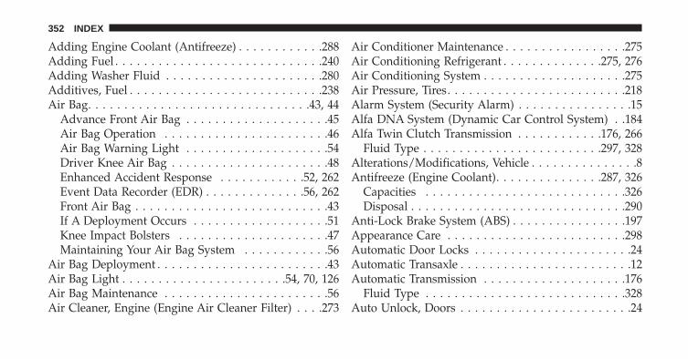
Adding Engine Coolant (Antifreeze) . . . . . . . . . . . .288Adding Fuel . . . . . . . . . . . . . . . . . . . . . . . . . . . . .240Adding Washer Fluid . . . . . . . . . . . . . . . . . . . . . .280Additives, Fuel . . . . . . . . . . . . . . . . . . . . . . . . . . .238Air Bag. . . . . . . . . . . . . . . . . . . . . . . . . . . . . . .43, 44
Advance Front Air Bag . . . . . . . . . . . . . . . . . . . .45Air Bag Operation . . . . . . . . . . . . . . . . . . . . . . .46Air Bag Warning Light . . . . . . . . . . . . . . . . . . . .54Driver Knee Air Bag . . . . . . . . . . . . . . . . . . . . . .48Enhanced Accident Response . . . . . . . . . . . .52, 262Event Data Recorder (EDR) . . . . . . . . . . . . . .56, 262Front Air Bag . . . . . . . . . . . . . . . . . . . . . . . . . . .43If A Deployment Occurs . . . . . . . . . . . . . . . . . . .51Knee Impact Bolsters . . . . . . . . . . . . . . . . . . . . .47Maintaining Your Air Bag System . . . . . . . . . . . .56
Air Bag Deployment . . . . . . . . . . . . . . . . . . . . . . . .43Air Bag Light . . . . . . . . . . . . . . . . . . . . . . .54, 70, 126Air Bag Maintenance . . . . . . . . . . . . . . . . . . . . . . .56Air Cleaner, Engine (Engine Air Cleaner Filter) . . . .273
Air Conditioner Maintenance . . . . . . . . . . . . . . . . .275Air Conditioning Refrigerant . . . . . . . . . . . . . .275, 276Air Conditioning System . . . . . . . . . . . . . . . . . . . .275Air Pressure, Tires. . . . . . . . . . . . . . . . . . . . . . . . .218Alarm System (Security Alarm) . . . . . . . . . . . . . . . .15Alfa DNA System (Dynamic Car Control System) . .184Alfa Twin Clutch Transmission . . . . . . . . . . . .176, 266
Fluid Type . . . . . . . . . . . . . . . . . . . . . . . . .297, 328Alterations/Modifications, Vehicle . . . . . . . . . . . . . . .8Antifreeze (Engine Coolant). . . . . . . . . . . . . . .287, 326
Capacities . . . . . . . . . . . . . . . . . . . . . . . . . . . .326Disposal . . . . . . . . . . . . . . . . . . . . . . . . . . . . . .290
Anti-Lock Brake System (ABS) . . . . . . . . . . . . . . . .197Appearance Care . . . . . . . . . . . . . . . . . . . . . . . . .298Automatic Door Locks . . . . . . . . . . . . . . . . . . . . . .24Automatic Transaxle . . . . . . . . . . . . . . . . . . . . . . . .12Automatic Transmission . . . . . . . . . . . . . . . . . . . .176
Fluid Type . . . . . . . . . . . . . . . . . . . . . . . . . . . .328Auto Unlock, Doors . . . . . . . . . . . . . . . . . . . . . . . .24
352 INDEX
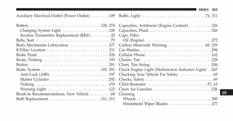
Auxiliary Electrical Outlet (Power Outlet) . . . . . . . .109
Battery . . . . . . . . . . . . . . . . . . . . . . . . . . . . .128, 274Charging System Light . . . . . . . . . . . . . . . . . . .128Keyless Transmitter Replacement (RKE) . . . . . . . .20
Belts, Seat . . . . . . . . . . . . . . . . . . . . . . . . . . . . . . .70Body Mechanism Lubrication . . . . . . . . . . . . . . . . .277B-Pillar Location . . . . . . . . . . . . . . . . . . . . . . . . . .211Brake Fluid . . . . . . . . . . . . . . . . . . . . . . . . . . . . .328Brake, Parking . . . . . . . . . . . . . . . . . . . . . . . . . . .193Brakes . . . . . . . . . . . . . . . . . . . . . . . . . . . . . . . . .291Brake System . . . . . . . . . . . . . . . . . . . . . . . . .195, 291
Anti-Lock (ABS) . . . . . . . . . . . . . . . . . . . . . . . .197Master Cylinder . . . . . . . . . . . . . . . . . . . . . . . .292Parking . . . . . . . . . . . . . . . . . . . . . . . . . . . . . .193Warning Light . . . . . . . . . . . . . . . . . . . . . . . . .122
Break-In Recommendations, New Vehicle . . . . . . . . .68Bulb Replacement. . . . . . . . . . . . . . . . . . . . . .311, 313
Bulbs, Light . . . . . . . . . . . . . . . . . . . . . . . . . . .71, 311
Capacities, Antifreeze (Engine Coolant) . . . . . . . . . .326Capacities, Fluid . . . . . . . . . . . . . . . . . . . . . . . . . .326Caps, Filler
Oil (Engine) . . . . . . . . . . . . . . . . . . . . . . . . . . .272Carbon Monoxide Warning . . . . . . . . . . . . . . . .69, 239Car Washes . . . . . . . . . . . . . . . . . . . . . . . . . . . . .298Cellular Phone . . . . . . . . . . . . . . . . . . . . . . . . . . .162Chains, Tire . . . . . . . . . . . . . . . . . . . . . . . . . . . . .228Chart, Tire Sizing . . . . . . . . . . . . . . . . . . . . . . . . .206Check Engine Light (Malfunction Indicator Light) . .267Checking Your Vehicle For Safety . . . . . . . . . . . . . . .69Checks, Safety . . . . . . . . . . . . . . . . . . . . . . . . . . . .69Child Restraint . . . . . . . . . . . . . . . . . . . . . . . . .57, 63Clean Air Gasoline . . . . . . . . . . . . . . . . . . . . . . . .236Cleaning
Wheels . . . . . . . . . . . . . . . . . . . . . . . . . . . . . . .300Windshield Wiper Blades . . . . . . . . . . . . . . . . . .277
10
INDEX 353
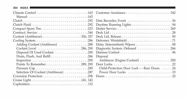
Climate Control . . . . . . . . . . . . . . . . . . . . . . . . . .163Manual . . . . . . . . . . . . . . . . . . . . . . . . . . . . . .163
Clutch . . . . . . . . . . . . . . . . . . . . . . . . . . . . . . . . .292Clutch Fluid . . . . . . . . . . . . . . . . . . . . . . . . . . . . .292Compact Spare Tire . . . . . . . . . . . . . . . . . . . . . . . .223Contract, Service . . . . . . . . . . . . . . . . . . . . . . . . . .344Coolant (Antifreeze) . . . . . . . . . . . . . . . . . . . .326, 327Cooling System. . . . . . . . . . . . . . . . . . . . . . . . . . .286
Adding Coolant (Antifreeze) . . . . . . . . . . . . . . .288Coolant Level . . . . . . . . . . . . . . . . . . . . . .286, 290Disposal Of Used Coolant . . . . . . . . . . . . . . . . .290Drain, Flush, And Refill . . . . . . . . . . . . . . . . . . .286Inspection . . . . . . . . . . . . . . . . . . . . . . . . . . . .290Points To Remember . . . . . . . . . . . . . . . . . .289, 290Pressure Cap . . . . . . . . . . . . . . . . . . . . . . . . . .289Selection Of Coolant (Antifreeze) . . . . . . . . . . . .287
Corrosion Protection . . . . . . . . . . . . . . . . . . . . . . .298Cruise Light. . . . . . . . . . . . . . . . . . . . . . . . . .141, 142Cupholders. . . . . . . . . . . . . . . . . . . . . . . . . . . . . .112
Customer Assistance . . . . . . . . . . . . . . . . . . . . . . .342
Data Recorder, Event . . . . . . . . . . . . . . . . . . . . . . .56Daytime Running Lights . . . . . . . . . . . . . . . . . . . . .94Dealer Service. . . . . . . . . . . . . . . . . . . . . . . . . . . .269Deck Lid . . . . . . . . . . . . . . . . . . . . . . . . . . . . . . . .28Deck Lid, Release . . . . . . . . . . . . . . . . . . . . . . . . . .90Defroster, Windshield . . . . . . . . . . . . . . . . . . . . . . .71Delay (Intermittent) Wipers . . . . . . . . . . . . . . . . . . .98Diagnostic System, Onboard . . . . . . . . . . . . . . . . .266Dimmer Control . . . . . . . . . . . . . . . . . . . . . . . . . . .96Disposal
Antifreeze (Engine Coolant) . . . . . . . . . . . . . . . .290Door Locks . . . . . . . . . . . . . . . . . . . . . . . . . . . . . .22
Child-Protection Door Lock — Rear Doors . . . . . .24Power Door Locks . . . . . . . . . . . . . . . . . . . . . . .19
Doors . . . . . . . . . . . . . . . . . . . . . . . . . . . . . . . . . .22
354 INDEX
DrivingThrough Flowing, Rising, Or Shallow StandingWater . . . . . . . . . . . . . . . . . . . . . . . . . . . . . . . .191
Electrical Outlet, Auxiliary (Power Outlet) . . . . . . . .109Electrical Power Outlets. . . . . . . . . . . . . . . . . . . . .109Electric Remote Mirrors. . . . . . . . . . . . . . . . . . . . . .77Electronic Brake Control System . . . . . . . . . . . . . . .195Electronic Speed Control (Cruise Control) . . . . . . . .101Electronic Throttle Control Warning Light . . . . . . . .125Electronic Vehicle Information Center (EVIC)
Activation Trip Data (Trip B On) . . . . . . . . . . . .148Autoclose . . . . . . . . . . . . . . . . . . . . . . . . . . . . .151Average Fuel Consumption . . . . . . . . . . . . . . . .159Average Speed . . . . . . . . . . . . . . . . . . . . . . . . .160Buzzer Volume (Adjusting The Failure/WarningBuzzer Volume) . . . . . . . . . . . . . . . . . . . . . . . .153Change Engine Oil . . . . . . . . . . . . . . . . . . . . . .155Change Engine Oil Indicator System . . . . . . . . . .155
Daytime Running Lamps (DRL) . . . . . . . . . . . . .155Distance Traveled . . . . . . . . . . . . . . . . . . . . . . .159Electronic Vehicle Information Center (EVIC) . . . .144Electronic Vehicle Information Center (EVIC)Setup Menu . . . . . . . . . . . . . . . . . . . . . . . . . . .146Exit Menu . . . . . . . . . . . . . . . . . . . . . . . . . . . .155Exit Trip . . . . . . . . . . . . . . . . . . . . . . . . . . . . . .158Fuel Range . . . . . . . . . . . . . . . . . . . . . . . . . . . .159Indications On Display . . . . . . . . . . . . . . . . . . .158Instant Fuel Consumption . . . . . . . . . . . . . . . . .160Language (Selecting The Language) . . . . . . . . . .153New Trip . . . . . . . . . . . . . . . . . . . . . . . . . . . . .157Oil Life . . . . . . . . . . . . . . . . . . . . . . . . . . . . . .155Service (Scheduled Servicing) . . . . . . . . . . . . . . .154Set Date . . . . . . . . . . . . . . . . . . . . . . . . . . . . . .150Speed Beep (Speed Limit) . . . . . . . . . . . . . . . . .147Start Of Trip Procedure . . . . . . . . . . . . . . . . . . .158Time Adjustment (Clock) . . . . . . . . . . . . . . . . . .149Travel Time . . . . . . . . . . . . . . . . . . . . . . . . . . .160
10
INDEX 355
Trip Button . . . . . . . . . . . . . . . . . . . . . . . . . . . .156Trip Computer . . . . . . . . . . . . . . . . . . . . . . . . .156Trip Functions . . . . . . . . . . . . . . . . . . . . . . . . .157Units (Set Units) . . . . . . . . . . . . . . . . . . . . . . . .152Values Displayed . . . . . . . . . . . . . . . . . . . . . . .158
Emergency, In Case OfHazard Warning Flasher . . . . . . . . . . . . . . . . . .246Jump Starting . . . . . . . . . . . . . . . . . . . . . . . . . .254Overheating . . . . . . . . . . . . . . . . . . . . . . . . . . .246
Emission Control System Maintenance . . . . . . . . . .267Engine
Air Cleaner . . . . . . . . . . . . . . . . . . . . . . . . . . .273Break-In Recommendations . . . . . . . . . . . . . . . . .68Checking Oil Level . . . . . . . . . . . . . . . . . . . . . .271Compartment . . . . . . . . . . . . . . . . . . . . . . . . . .265Cooling . . . . . . . . . . . . . . . . . . . . . . . . . . . . . .286Exhaust Gas Caution . . . . . . . . . . . . . . . . . .69, 239Fails To Start . . . . . . . . . . . . . . . . . . . . . . . . . .175Flooded, Starting . . . . . . . . . . . . . . . . . . . . . . .175
Fuel Requirements . . . . . . . . . . . . . . . . . . . . . .235Jump Starting . . . . . . . . . . . . . . . . . . . . . . . . . .254Oil . . . . . . . . . . . . . . . . . . . . . . . . . . . . . .271, 326Oil Filler Cap . . . . . . . . . . . . . . . . . . . . . . . . . .272Oil Filter . . . . . . . . . . . . . . . . . . . . . . . . . . . . .273Oil Selection . . . . . . . . . . . . . . . . . . . . . . . . . . .272Overheating . . . . . . . . . . . . . . . . . . . . . . . . . . .246Starting . . . . . . . . . . . . . . . . . . . . . . . . . . . . . .174
Enhanced Accident Response Feature. . . . . . . . .52, 262Ethanol . . . . . . . . . . . . . . . . . . . . . . . . . . . . . . . .236Euro Twin Clutch Transmission
Fluid Type . . . . . . . . . . . . . . . . . . . . . . . . . . . .297Event Data Recorder . . . . . . . . . . . . . . . . . . . . . . . .56Exhaust Gas Caution . . . . . . . . . . . . . . . . . . . .69, 239Exhaust System . . . . . . . . . . . . . . . . . . . . . . . .69, 283Exterior Lights . . . . . . . . . . . . . . . . . . . . . . . . . . . .71
FiltersAir Cleaner . . . . . . . . . . . . . . . . . . . . . . . . . . .273
356 INDEX
Engine Fuel . . . . . . . . . . . . . . . . . . . . . . . . . . .327Engine Oil . . . . . . . . . . . . . . . . . . . . . . . . . . . .273Engine Oil Disposal . . . . . . . . . . . . . . . . . . . . .272
FlashersHazard Warning . . . . . . . . . . . . . . . . . . . . . . . .246Turn Signal . . . . . . . . . . . . . . . . . . . . . . . . .71, 139
Flooded Engine Starting . . . . . . . . . . . . . . . . . . . .175Fluid, Brake . . . . . . . . . . . . . . . . . . . . . . . . . . . . .328Fluid Capacities . . . . . . . . . . . . . . . . . . . . . . . . . .326Fluid Leaks . . . . . . . . . . . . . . . . . . . . . . . . . . . . . .72Fluids, Lubricants And Genuine Parts . . . . . . . . . . .327Four-Way Hazard Flasher . . . . . . . . . . . . . . . . . . .246Fuel . . . . . . . . . . . . . . . . . . . . . . . . . . . . . . . . . . .235
Adding . . . . . . . . . . . . . . . . . . . . . . . . . . . . . .240Additives . . . . . . . . . . . . . . . . . . . . . . . . . . . . .238Capacity . . . . . . . . . . . . . . . . . . . . . . . . . . . . .326Clean Air . . . . . . . . . . . . . . . . . . . . . . . . . . . . .236Ethanol . . . . . . . . . . . . . . . . . . . . . . . . . . . . . .236Gasoline . . . . . . . . . . . . . . . . . . . . . . . . . . . . . .235
Materials Added . . . . . . . . . . . . . . . . . . . . . . . .238Methanol . . . . . . . . . . . . . . . . . . . . . . . . . . . . .236Octane Rating . . . . . . . . . . . . . . . . . . . . . . . . . .235Requirements . . . . . . . . . . . . . . . . . . . . . . . . . .235Tank Capacity . . . . . . . . . . . . . . . . . . . . . . . . . .326
Fueling . . . . . . . . . . . . . . . . . . . . . . . . . . . . . . . .240Fuses . . . . . . . . . . . . . . . . . . . . . . . . . . . . . . . . . .306
Gasoline, Clean Air . . . . . . . . . . . . . . . . . . . . . . . .236Gasoline (Fuel) . . . . . . . . . . . . . . . . . . . . . . . .235, 326Gasoline, Reformulated . . . . . . . . . . . . . . . . . . . . .236General Information . . . . . . . . . . . . . . . . . . . .163, 235General Maintenance. . . . . . . . . . . . . . . . . . . . . . .270Glass Cleaning . . . . . . . . . . . . . . . . . . . . . . . . . . .304
HazardDriving Through Flowing, Rising, Or ShallowStanding Water . . . . . . . . . . . . . . . . . . . . . . . . .191
Hazard Warning Flasher . . . . . . . . . . . . . . . . . . . .246
10
INDEX 357
Headlights . . . . . . . . . . . . . . . . . . . . . . . . . . . . . . .94Cleaning . . . . . . . . . . . . . . . . . . . . . . . . . . . . .304Passing . . . . . . . . . . . . . . . . . . . . . . . . . . . . . . .95
Head Restraints . . . . . . . . . . . . . . . . . . . . . . . . . . .89Heated Mirrors. . . . . . . . . . . . . . . . . . . . . . . . . . . .78Heater . . . . . . . . . . . . . . . . . . . . . . . . . . . . . .163, 165Holder, Cup . . . . . . . . . . . . . . . . . . . . . . . . . . . . .112
Ignition . . . . . . . . . . . . . . . . . . . . . . . . . . . . . . . . .12Key . . . . . . . . . . . . . . . . . . . . . . . . . . . . . . .11, 12
Ignition Key Removal . . . . . . . . . . . . . . . . . . . . . . .12Illuminated Entry . . . . . . . . . . . . . . . . . . . . . . . . . .18Immobilizer (Sentry Key) . . . . . . . . . . . . . . . . . . . .14Infant Restraint . . . . . . . . . . . . . . . . . . . . . . . . .57, 60Inside Rearview Mirror . . . . . . . . . . . . . . . . . . . . . .76Instrument Cluster . . . . . . . . . . . . . . . . . . . . .129, 139
Instrument Cluster . . . . . . . . . . . . . . . . . . . . . .119Instrument Panel And Controls . . . . . . . . . . . . . . .118Instrument Panel Cover . . . . . . . . . . . . . . . . . . . . .304
Instrument Panel Lens Cleaning . . . . . . . . . . . . . . .305Interior Appearance Care . . . . . . . . . . . . . . . . . . . .302Interior Lights . . . . . . . . . . . . . . . . . . . . . . . . . . . .97Intermittent Wipers (Delay Wipers) . . . . . . . . . . . . .98Introduction . . . . . . . . . . . . . . . . . . . . . . . . . . . . . .4
Jump Starting . . . . . . . . . . . . . . . . . . . . . . . . . . . .254
Key FobLock The Doors . . . . . . . . . . . . . . . . . . . . . . . . .19Unlock The Doors . . . . . . . . . . . . . . . . . . . . . . .19
Key-In Reminder . . . . . . . . . . . . . . . . . . . . . . . . . .14Key, Replacement . . . . . . . . . . . . . . . . . . . . . . . . . .15Keys . . . . . . . . . . . . . . . . . . . . . . . . . . . . . . . . . . .11Key, Sentry (Immobilizer) . . . . . . . . . . . . . . . . . . . .14
Lane Change Assist . . . . . . . . . . . . . . . . . . . . . . . .95Lap/Shoulder Belts. . . . . . . . . . . . . . . . . . . . . . . . .34Latches . . . . . . . . . . . . . . . . . . . . . . . . . . . . . . . . .72
358 INDEX
Lead Free Gasoline . . . . . . . . . . . . . . . . . . . . . . . .235Leaks, Fluid . . . . . . . . . . . . . . . . . . . . . . . . . . . . . .72Life Of Tires . . . . . . . . . . . . . . . . . . . . . . . . . . . . .226Light Bulbs . . . . . . . . . . . . . . . . . . . . . . . . . . .71, 311Lights . . . . . . . . . . . . . . . . . . . . . . . . . . . . .71, 93, 94
Air Bag . . . . . . . . . . . . . . . . . . . . . . . . .54, 70, 126Brake Warning . . . . . . . . . . . . . . . . . . . . . . . . .122Bulb Replacement . . . . . . . . . . . . . . . . . . . . . . .313Cruise . . . . . . . . . . . . . . . . . . . . . . . . . . . .141, 142Engine Temperature Warning . . . . . . . . . . . . . . .129Exterior . . . . . . . . . . . . . . . . . . . . . . . . . . . . . . .71Hazard Warning Flasher . . . . . . . . . . . . . . . . . .246Illuminated Entry . . . . . . . . . . . . . . . . . . . . . . . .18Interior . . . . . . . . . . . . . . . . . . . . . . . . . . . . . . .97Malfunction Indicator (Check Engine) . . . . . . . . .136Park . . . . . . . . . . . . . . . . . . . . . . . . . . . . . .95, 140Passing . . . . . . . . . . . . . . . . . . . . . . . . . . . . . . .95Seat Belt Reminder . . . . . . . . . . . . . . . . . . . . . .127Service . . . . . . . . . . . . . . . . . . . . . . . . . . . . . . .313
Tire Pressure Monitoring (TPMS) . . . . . . . . . . . .130Turn Signal . . . . . . . . . . . . . . . . . . . . . . . . .71, 139Warning (Instrument Cluster Description) . . .129, 139
Loading VehicleTires . . . . . . . . . . . . . . . . . . . . . . . . . . . . . . . .211
Locks . . . . . . . . . . . . . . . . . . . . . . . . . . . . . . . . . .22Auto Unlock . . . . . . . . . . . . . . . . . . . . . . . . . . .24Door . . . . . . . . . . . . . . . . . . . . . . . . . . . . . . . . .22Power Door . . . . . . . . . . . . . . . . . . . . . . . . . . . .22
Lubrication, Body . . . . . . . . . . . . . . . . . . . . . . . . .277Lug Nuts . . . . . . . . . . . . . . . . . . . . . . . . . . . . . . .248
Maintenance Free Battery. . . . . . . . . . . . . . . . . . . .274Maintenance, General . . . . . . . . . . . . . . . . . . . . . .270Maintenance Procedures . . . . . . . . . . . . . . . . . . . .270Maintenance Schedule . . . . . . . . . . . . . . . . . . . . . .330Malfunction Indicator Light (Check Engine) . . .136, 267Manual, Service . . . . . . . . . . . . . . . . . . . . . . . . . .346Manual Transmission
10
INDEX 359
Lubricant Selection . . . . . . . . . . . . . . . . . . . . . .328Master Cylinder (Brakes) . . . . . . . . . . . . . . . . . . . .292Methanol . . . . . . . . . . . . . . . . . . . . . . . . . . . . . . .236Mirrors . . . . . . . . . . . . . . . . . . . . . . . . . . . . . . . . .76
Electric Remote . . . . . . . . . . . . . . . . . . . . . . . . .77Heated . . . . . . . . . . . . . . . . . . . . . . . . . . . . . . .78Outside . . . . . . . . . . . . . . . . . . . . . . . . . . . . . . .77Rearview . . . . . . . . . . . . . . . . . . . . . . . . . . . . . .76
Modifications/Alterations, Vehicle . . . . . . . . . . . . . . .8Monitor, Tire Pressure System . . . . . . . . . . . . . . . .230MTBE/ETBE . . . . . . . . . . . . . . . . . . . . . . . . . . . .236Multi-Function Control Lever . . . . . . . . . . . . . . . . .94
New Vehicle Break-In Period . . . . . . . . . . . . . . . . . .68
Occupant Restraints . . . . . . . . . . . . . . . . . . . . . . . .30Octane Rating, Gasoline (Fuel) . . . . . . . . . . . . . . . .235Oil, Engine . . . . . . . . . . . . . . . . . . . . . . .271, 326, 327
Capacity . . . . . . . . . . . . . . . . . . . . . . . . . . . . .326
Change Interval . . . . . . . . . . . . . . . . . . . . . . . .271Checking . . . . . . . . . . . . . . . . . . . . . . . . . . . . .271Disposal . . . . . . . . . . . . . . . . . . . . . . . . . . . . . .272Filter . . . . . . . . . . . . . . . . . . . . . . . . . . . . . . . .273Filter Disposal . . . . . . . . . . . . . . . . . . . . . . . . .272Materials Added To . . . . . . . . . . . . . . . . . . . . . .272Pressure Warning Light . . . . . . . . . . . . . . . . . . .124Recommendation . . . . . . . . . . . . . . . . . . . .272, 326Viscosity . . . . . . . . . . . . . . . . . . . . . . . . . . . . .272
Oil Filter, Change . . . . . . . . . . . . . . . . . . . . . . . . .273Oil Filter, Selection . . . . . . . . . . . . . . . . . . . . . . . .273Oil Pressure Light . . . . . . . . . . . . . . . . . . . . . . . . .124Onboard Diagnostic System . . . . . . . . . . . . . . . . . .266Operating Precautions . . . . . . . . . . . . . . . . . . . . . .266Operator Manual (Owner’s Manual) . . . . . . . . . . . . .5Outside Rearview Mirrors . . . . . . . . . . . . . . . . . . . .77Overheating, Engine . . . . . . . . . . . . . . . . . . . . . . .246Owner’s Manual (Operator Manual) . . . . . . . . . .5, 346
360 INDEX
Paint Care . . . . . . . . . . . . . . . . . . . . . . . . . . . . . .298Parking Brake. . . . . . . . . . . . . . . . . . . . . . . . . . . .193Passing Light . . . . . . . . . . . . . . . . . . . . . . . . . . . . .95Pets. . . . . . . . . . . . . . . . . . . . . . . . . . . . . . . . . . . .67Pets, Transporting. . . . . . . . . . . . . . . . . . . . . . . . . .67Placard, Tire And Loading Information . . . . . . . . . .212Power
Door Locks . . . . . . . . . . . . . . . . . . . . . . . . . . . .22Mirrors . . . . . . . . . . . . . . . . . . . . . . . . . . . . . . .77Windows . . . . . . . . . . . . . . . . . . . . . . . . . . . . . .26
Pregnant Women And Seat Belts . . . . . . . . . . . . . . .40Pretensioners
Seat Belts . . . . . . . . . . . . . . . . . . . . . . . . . . . . . .40
Radial Ply Tires . . . . . . . . . . . . . . . . . . . . . . . . . .219Radio Frequency
General Information . . . . . . . . . . . . . . . . . . .15, 22Radio Operation . . . . . . . . . . . . . . . . . . . . . . . . . .162Reclining Front Seats . . . . . . . . . . . . . . . . . . . . . . .88
Recorder, Event Data . . . . . . . . . . . . . . . . . . . . . . .56Recreational Towing . . . . . . . . . . . . . . . . . . . . . . .243Reformulated Gasoline . . . . . . . . . . . . . . . . . . . . .236Refrigerant . . . . . . . . . . . . . . . . . . . . . . . . . . . . . .276Reminder, Seat Belt. . . . . . . . . . . . . . . . . . . . . . . . .32Remote Keyless Entry (RKE)
Remote Keyless Entry (RKE) . . . . . . . . . . . . . . . .18Unlock The Doors . . . . . . . . . . . . . . . . . . . . . . .19
Replacement Bulbs . . . . . . . . . . . . . . . . . . . . . . . .311Replacement Keys . . . . . . . . . . . . . . . . . . . . . . . . .15Replacement Parts. . . . . . . . . . . . . . . . . . . . . . . . .269Replacement Tires . . . . . . . . . . . . . . . . . . . . . . . . .227Reporting Safety Defects . . . . . . . . . . . . . . . . . . . .345Restraint, Head . . . . . . . . . . . . . . . . . . . . . . . . . . .89Restraints, Child . . . . . . . . . . . . . . . . . . . . . . . . . . .57Restraints, Infant . . . . . . . . . . . . . . . . . . . . . . . . . .60Restraints, Occupant . . . . . . . . . . . . . . . . . . . . . . . .30Rotation, Tires . . . . . . . . . . . . . . . . . . . . . . . . . . .230
10
INDEX 361
Safety Checks Inside Vehicle . . . . . . . . . . . . . . . . . .70Safety Checks Outside Vehicle . . . . . . . . . . . . . . . . .71Safety Defects, Reporting . . . . . . . . . . . . . . . . . . . .345Safety, Exhaust Gas. . . . . . . . . . . . . . . . . . . . . . . . .69Safety Information, Tire . . . . . . . . . . . . . . . . . . . . .204Safety Tips . . . . . . . . . . . . . . . . . . . . . . . . . . . . . . .69Schedule, Maintenance . . . . . . . . . . . . . . . . . . . . .330Seat Belt
Automatic Locking Retractor (ALR) . . . . . . . . . . .41Energy Management Feature . . . . . . . . . . . . . . . .41Lap/Shoulder Belt Operation . . . . . . . . . . . . . . . .37Lap/Shoulder Belts . . . . . . . . . . . . . . . . . . . . . . .34Lap/Shoulder Belt Untwisting . . . . . . . . . . . . . . .39Pregnant Women . . . . . . . . . . . . . . . . . . . . . . . .40Seat Belt Pretensioner . . . . . . . . . . . . . . . . . . . . .40Seat Belt Reminder . . . . . . . . . . . . . . . . . . . . . . .32Seat Belt System . . . . . . . . . . . . . . . . . . . . . . . . .30
Seat Belt Maintenance . . . . . . . . . . . . . . . . . . . . . .305Seat Belt Reminder . . . . . . . . . . . . . . . . . . . . . . . . .32
Seat Belts . . . . . . . . . . . . . . . . . . . . . . . . . . . . .32, 70Child Restraint . . . . . . . . . . . . . . . . . . . . .57, 60, 63Front Seat . . . . . . . . . . . . . . . . . . . . . . . .32, 34, 37Inspection . . . . . . . . . . . . . . . . . . . . . . . . . . . . .70Operating Instructions . . . . . . . . . . . . . . . . . . . .37Pregnant Women . . . . . . . . . . . . . . . . . . . . . . . .40Pretensioners . . . . . . . . . . . . . . . . . . . . . . . . . . .40Rear Seat . . . . . . . . . . . . . . . . . . . . . . . . . . . . . .34Reminder . . . . . . . . . . . . . . . . . . . . . . . . . . . . .127Untwisting Procedure . . . . . . . . . . . . . . . . . . . . .39
Seats . . . . . . . . . . . . . . . . . . . . . . . . . . . . . . . . . . .86Adjustment . . . . . . . . . . . . . . . . . . . . . . . . . .86, 87Reclining . . . . . . . . . . . . . . . . . . . . . . . . . . . . . .88
Security Alarm . . . . . . . . . . . . . . . . . . . . . . . . . . . .15Sentry Key (Immobilizer) . . . . . . . . . . . . . . . . . . . .14Service Assistance . . . . . . . . . . . . . . . . . . . . . . . . .342Service Contract . . . . . . . . . . . . . . . . . . . . . . . . . .344Service Manuals . . . . . . . . . . . . . . . . . . . . . . . . . .346Shoulder Belts . . . . . . . . . . . . . . . . . . . . . . . . . . . .34
362 INDEX
Signals, Turn . . . . . . . . . . . . . . . . . . . . . . . . . .71, 139Snow Chains (Tire Chains) . . . . . . . . . . . . . . . . . . .228Snow Tires . . . . . . . . . . . . . . . . . . . . . . . . . . . . . .221Spare Tire . . . . . . . . . . . . . . . . . . . . . . . .222, 223, 224Spark Plugs . . . . . . . . . . . . . . . . . . . . . . . . . . . . .327Speed Control
Accel/Decel . . . . . . . . . . . . . . . . . . . . . . . . . . .104Speed Control (Cruise Control). . . . . . . . . . . . . . . .101Starting . . . . . . . . . . . . . . . . . . . . . . . . . . . . . . . .174
Automatic Transmission . . . . . . . . . . . . . . . . . .174Cold Weather . . . . . . . . . . . . . . . . . . . . . . . . . .175Engine Fails To Start . . . . . . . . . . . . . . . . . . . . .175
SteeringColumn Lock . . . . . . . . . . . . . . . . . . . . . . . . . .100Tilt Column . . . . . . . . . . . . . . . . . . . . . . . . . . .100Wheel, Tilt . . . . . . . . . . . . . . . . . . . . . . . . . . . .100
Storage. . . . . . . . . . . . . . . . . . . . . . . . . . . . . . . . .311Storage, Vehicle. . . . . . . . . . . . . . . . . . . . . . . . . . .311Storing Your Vehicle . . . . . . . . . . . . . . . . . . . . . . .311
Supplemental Restraint System - Air Bag . . . . . . . . .44
Telescoping Steering Column . . . . . . . . . . . . . . . . .100Tilt Steering Column . . . . . . . . . . . . . . . . . . . . . . .100Tire And Loading Information Placard . . . . . . .211, 212Tire Markings . . . . . . . . . . . . . . . . . . . . . . . . . . . .204Tires . . . . . . . . . . . . . . . . . . . . . . . . .71, 216, 222, 347
Aging (Life Of Tires) . . . . . . . . . . . . . . . . . . . . .226Air Pressure . . . . . . . . . . . . . . . . . . . . . . . . . . .216Chains . . . . . . . . . . . . . . . . . . . . . . . . . . . . . . .228Compact Spare . . . . . . . . . . . . . . . . . . . . . . . . .223General Information . . . . . . . . . . . . . . . . . .216, 222High Speed . . . . . . . . . . . . . . . . . . . . . . . . . . .219Inflation Pressures . . . . . . . . . . . . . . . . . . . . . . .218Life Of Tires . . . . . . . . . . . . . . . . . . . . . . . . . . .226Load Capacity . . . . . . . . . . . . . . . . . . . . . .211, 212Pressure Monitor System (TPMS) . . . . . . . . . . . .230Pressure Warning Light . . . . . . . . . . . . . . . . . . .130Quality Grading . . . . . . . . . . . . . . . . . . . . . . . .347
10
INDEX 363
Radial . . . . . . . . . . . . . . . . . . . . . . . . . . . . . . .219Replacement . . . . . . . . . . . . . . . . . . . . . . . . . . .227Rotation . . . . . . . . . . . . . . . . . . . . . . . . . . . . . .230Safety . . . . . . . . . . . . . . . . . . . . . . . . . . . .204, 216Sizes . . . . . . . . . . . . . . . . . . . . . . . . . . . . . . . .206Snow Tires . . . . . . . . . . . . . . . . . . . . . . . . . . . .221Spare Tire . . . . . . . . . . . . . . . . . . . . . . . . .222, 224Spinning . . . . . . . . . . . . . . . . . . . . . . . . . . . . .225Tread Wear Indicators . . . . . . . . . . . . . . . . . . . .225
Tire Safety Information . . . . . . . . . . . . . . . . . . . . .204To Open Deck Lid . . . . . . . . . . . . . . . . . . . . . . . . .90Towing . . . . . . . . . . . . . . . . . . . . . . . . . . . . . . . .243
Recreational . . . . . . . . . . . . . . . . . . . . . . . . . . .243Towing Eyes. . . . . . . . . . . . . . . . . . . . . . . . . . . . .258Towing Vehicle Behind A Motorhome . . . . . . . . . . .243Traction . . . . . . . . . . . . . . . . . . . . . . . . . . . . . . . .190Trailer Towing . . . . . . . . . . . . . . . . . . . . . . . . . . .243Transaxle
Automatic . . . . . . . . . . . . . . . . . . . . . . . . . . . . .12
Transmission . . . . . . . . . . . . . . . . . . . . . . . . . . . .177Automatic . . . . . . . . . . . . . . . . . . . . . . . . . . . .176Fluid . . . . . . . . . . . . . . . . . . . . . . . . . . . . . . . .296Maintenance . . . . . . . . . . . . . . . . . . . . . . . . . . .296
Transmitter Battery Service (Remote Keyless Entry) . .20Transporting Passengers . . . . . . . . . . . . . . . . . . . . .69Transporting Pets . . . . . . . . . . . . . . . . . . . . . . . . . .67Tread Wear Indicators . . . . . . . . . . . . . . . . . . . . . .225Turn Signals . . . . . . . . . . . . . . . . . . . . . . . . . . . . .139
Uniform Tire Quality Grades . . . . . . . . . . . . . . . . .347Unleaded Gasoline . . . . . . . . . . . . . . . . . . . . . . . .235Untwisting Procedure, Seat Belt . . . . . . . . . . . . . . . .39
Vehicle Identification Number (VIN) . . . . . . . . . . . . .7Vehicle Loading . . . . . . . . . . . . . . . . . . . . . . . . . .212Vehicle Modifications/Alterations . . . . . . . . . . . . . . .8Vehicle Security Alarm (Security Alarm) . . . . . . . . . .15Vehicle Storage . . . . . . . . . . . . . . . . . . . . . . . . . . .311
364 INDEX
Ventilation System. . . . . . . . . . . . . . . . . . . . . . . . .163
Warning Flasher, Hazard . . . . . . . . . . . . . . . . . . . .246Warnings And Cautions . . . . . . . . . . . . . . . . . . . . . .7Warranty Information . . . . . . . . . . . . . . . . . . . .4, 345Washer
Adding Fluid . . . . . . . . . . . . . . . . . . . . . . . . . .280Washers, Windshield. . . . . . . . . . . . . . . . . . . . . . . .98Washing Vehicle . . . . . . . . . . . . . . . . . . . . . . . . . .298Water
Driving Through . . . . . . . . . . . . . . . . . . . . . . . .191Wheel And Wheel Trim . . . . . . . . . . . . . . . . . . . . .300Wheel And Wheel Trim Care . . . . . . . . . . . . . . . . .300Windows . . . . . . . . . . . . . . . . . . . . . . . . . . . . . . . .26
Power . . . . . . . . . . . . . . . . . . . . . . . . . . . . . . . .26Windshield Defroster . . . . . . . . . . . . . . . . . . . . . . .71Windshield Washers . . . . . . . . . . . . . . . . . . . . . . . .98Windshield Wiper Blades . . . . . . . . . . . . . . . . . . . .277Windshield Wipers . . . . . . . . . . . . . . . . . . . . . . . . .98
Wiper Blade Replacement . . . . . . . . . . . . . . . . . . .277Wipers, Intermittent . . . . . . . . . . . . . . . . . . . . . . . .98
10
INDEX 365
INSTALLATION OF RADIO TRANSMITTINGEQUIPMENTSpecial design considerations are incorporated into thisvehicle’s electronic system to provide immunity to radiofrequency signals. Mobile two-way radios and telephoneequipment must be installed properly by trained person-nel. The following must be observed during installation.
The positive power connection should be made directlyto the battery and fused as close to the battery as possible.The negative power connection should be made to bodysheet metal adjacent to the negative battery connection.This connection should not be fused.
Antennas for two-way radios should be mounted on theroof or the rear area of the vehicle. Care should be usedin mounting antennas with magnet bases. Magnets mayaffect the accuracy or operation of the compass onvehicles so equipped.
The antenna cable should be as short as practical androuted away from the vehicle wiring when possible. Useonly fully shielded coaxial cable.
Carefully match the antenna and cable to the radio toensure a low Standing Wave Ratio (SWR).
Mobile radio equipment with output power greater thannormal may require special precautions.
All installations should be checked for possible interfer-ence between the communications equipment and thevehicle’s electronic systems.

2 0 1 6
20
16
4C
SP
IDE
R
SPIDERThird Edition
Printed in U.S.A.
©2016 FCA US LLC. All Rights Reserved.ALFA ROMEO is a registered trademark ofFCA Group Marketing S.p.A., used with permission.
16SPDR-126-AC OW N E R ’ S M A N U A L


