30
2016 International Petroleum Environmental Conference HORIZONTAL DIRECTIONAL DRILLING AND WELL INSTALLATION AT SMALL SITES

2016 International Petroleum Environmental Conference
HORIZONTAL DIRECTIONAL DRILLING AND WELL INSTALLATION AT SMALL SITES

History of Horizontal Environmental Wells• Horizontal/Directional Oil Wells in the 1930s – Present
• Directional “River Crossings” in the 1970s
• Environmental Applications for the Department of Energy in 1988
• Utilized for Most Remediation Applications by 2015• Utilized for Most Remediation Applications by 2015

Environmental Applications• Sampling under
obstructions• Extraction techniques
– Groundwater– Free phase product –
NAPL and DNAPL– Vapors– Dual phase
• Thermal treatment– Hot air/steam injection
– Electrical resistance heating
• Dewatering
• Slope stability – Dual phase
• Injection techniques– ISCO– Nutrient injection– Air sparge– Bio sparge– Barriers – PRBs/HRx
• Slope stability
• Mine tailings
• Ground water production

Applications/Advantages of Horizontal WellsThree Major Advantages
• Geometry
• Access areas unreachable to vertical wells
• Minimal site impact

Directional Control
• The bit is navigated along a prescribed path
• The well need not be horizontal
• Bore path is design is based on – Allowable bending radius of drill pipe and well
materialsmaterials
– Geology
– Treatment objective
– Surface constraints

Directional Control/Steering
• The drill string is steered by pushing the drill pipe against an asymmetric bit with a hydraulic jet; “duck bill” or bent sub
• The force against the bit or sub forces the drill pipe in sub forces the drill pipe in direction of the bit orientation
• When the entire assembly is rotated, the drill string goes straight
• A sensor behind the bit sends the direction/orientation of the bit to the surface

Directional Control/Steering

Locating Technologies
• Several Options Available– Walkover/Radio Beacon
– Wireline• Oil Field Technology
• Short Steering Tool (SST)
– Gyroscopic – Gyroscopic
• Selection based on bore path, interference risk, depth and cost
• All methods have ± 0.5 – 2% depth accuracy
Drilling Fluids are Required
• Maintain hole stability
• Remove cuttings
• Limit drilling fluid loss to the formation
• Cool bit and steering tools
• Two types commonly utilized• Two types commonly utilized– Bentonite
– Biodegradable polymer

Well Materials (Screen & Casing)
• Similar materials to vertical well installations– PVC
– Carbon steel
– Stainless steel (304 and 316L)
– HDPE– HDPE
– Fiberglass

Continuous Well Installation
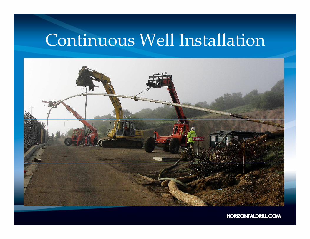
Continuous Well Installation

Blind Well Open Hole

Borepath/Well Geometry
• Terminology– Entry angle
– Tangent
– Radius of curvature (build radius)
– Horizontal section– Horizontal section
– True vertical depth
– Measured depth/pipe length
– Set back – determined by combination of the above

Borepath/Well Geometry

Drilling Equipment
• Drill rig
• Fluid cleaning/recycling system
• Pipe trailer
• Support vehicles– Water truck– Water truck
– Crew truck

Small Rig Set Up Area
• 7,000 lb. capacity rig
• 30’ x 50’ area
• Continuous well requires area at exit point

Sparge/SVE
• Former dry cleaning facility, Los Angeles Basin
• Active retail site
• Contaminant mass in soil and groundwater under building
• Remedy could not impact ongoing operations• Remedy could not impact ongoing operations
• Original plan included 20 vertical wells –businesses closed for 60 days for construction
• Horizontal wells to the rescue

Sparge/SVE
• Original design called for continuous wells– Three SVE
– Two sparge
• Site constraints altered design
• Blind well technology was utilized• Blind well technology was utilized– Three SVE wells: 99’ long, 4’ deep, 2” sch. 80 PVC
– Two sparge wells: 99’ long, 11’ deep, 2” sch. 80 PVC

SVE


Sparge/SVE
• All wells installed in three days with no impact to ongoing operations
• Soil vapor probe observed negative pressure 68’ from the horizontal well screen
• Concentration of PCE was reduced by 99% in • Concentration of PCE was reduced by 99% in three months– Data provided by Rincon Consultants, Inc.
• Mr. Torin Snyder
• 760.918.9444

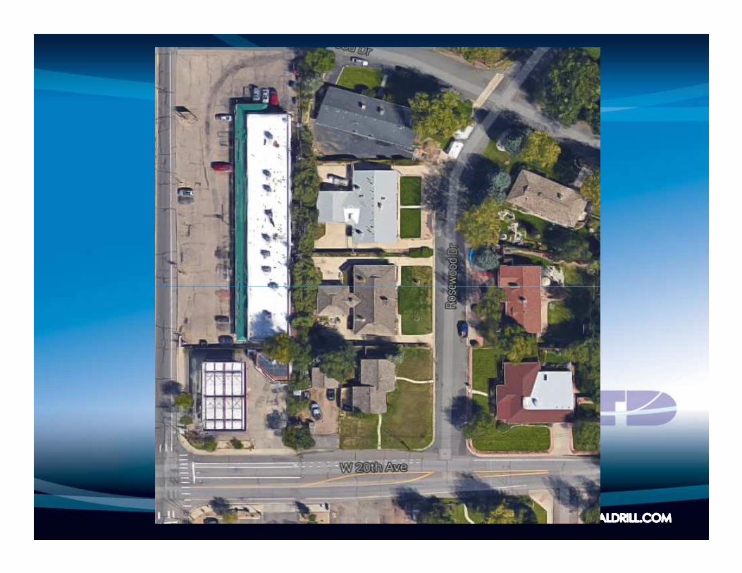
Western US Site
• Challenging site conditions– Highly urbanized/residential area
– Very small site
– No room for set back
– Cobbles from surface to 12’ bgs– Cobbles from surface to 12’ bgs
– Sparge and SVE well pair
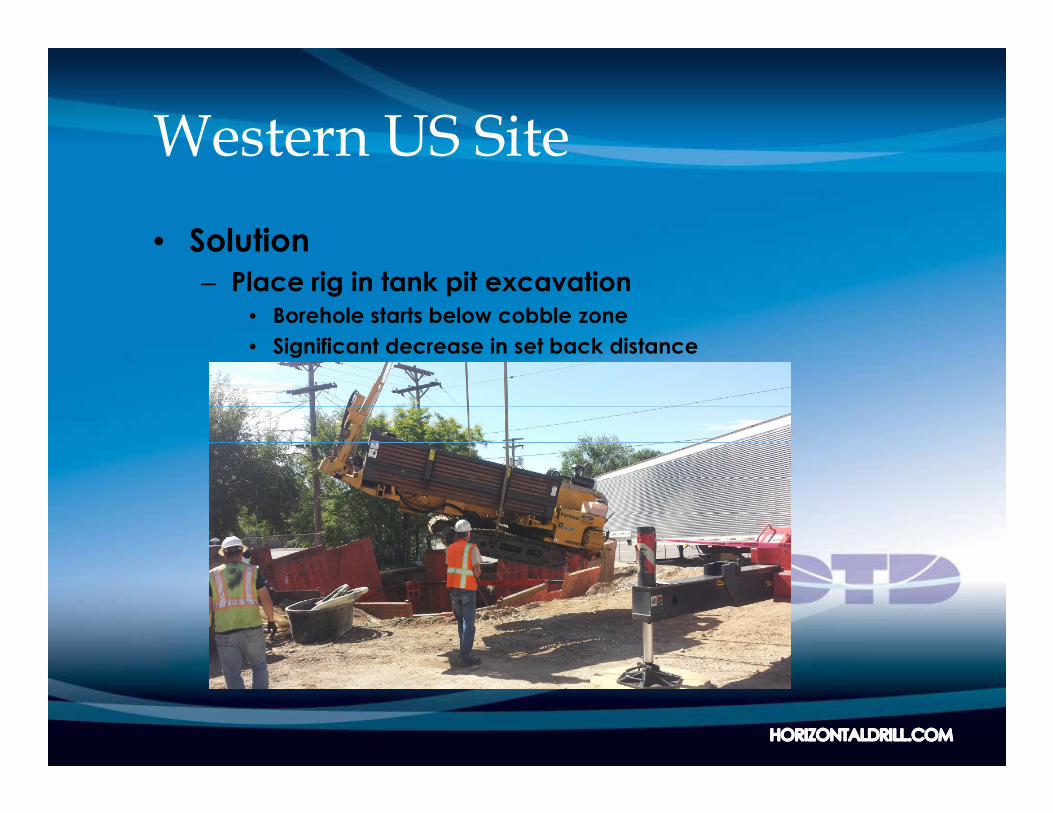
Western US Site
• Solution– Place rig in tank pit excavation
• Borehole starts below cobble zone
• Significant decrease in set back distance


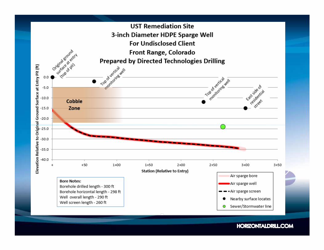
Western US Site
• Creative Thinking Overcame Site Challenges
• Total of 255’ of drilling
• Seven rig days
• Cost for drilling and well installation– $85,000 – $85,000
– $153/ft.
– Costs do not include excavation, shoring and waste containment and disposal

In Summary
• The technology is innovative - not experimental
• Horizontal wells are a proven, cost effective installation method
• Thousands of wells have been successfully completed in the UScompleted in the US
• Horizontal wells can be used with all remediation technologies
• The technology is innovative – not experimental


![State Environmental Planning Policy (Mining, … - Mining Petroleum Production...State Environmental Planning Policy (Mining, Petroleum Production and Extractive Industries) 2007 [2007-65]](https://static.documents.pub/doc/80x56/5aea10be7f8b9a66258b8d32/state-environmental-planning-policy-mining-mining-petroleum-productionstate.jpg)


