676
Renegade OWNER’S MANUAL 2016

RenegadeOW N E R ’ S M A N UA L
20
16 R
en
eg
ad
e
Fifth EditionPrinted in U.S.A.
16BU-126-AE©2016 FCA US LLC. All Rights Reserved.Jeep is a registered trademark of FCA US LLC.
2 0 1 6
STICK WITH THE SPECIALISTS®

VEHICLES SOLD IN CANADAWith respect to any Vehicles Sold in Canada, the name FCAUS LLC shall be deemed to be deleted and the name FCACanada Inc. used in substitution therefore.
DRIVING AND ALCOHOLDrunken driving is one of the most frequent causes ofaccidents.Your driving ability can be seriously impaired with bloodalcohol levels far below the legal minimum. If you aredrinking, don’t drive. Ride with a designated non-drinking driver, call a cab, a friend, or use public trans-portation.
WARNING!
Driving after drinking can lead to an accident.Your perceptions are less sharp, your reflexes areslower, and your judgment is impaired when youhave been drinking. Never drink and then drive.
This manual illustrates and describes the operation offeatures and equipment that are either standard or op-tional on this vehicle. This manual may also include adescription of features and equipment that are no longeravailable or were not ordered on this vehicle. Pleasedisregard any features and equipment described in thismanual that are not on this vehicle.
FCA US LLC reserves the right to make changes in designand specifications, and/or make additions to or improve-ments to its products without imposing any obligationupon itself to install them on products previously manu-factured.
Copyright © 2016 FCA US LLC

TABLE OF CONTENTSSECTION PAGE
1 INTRODUCTION . . . . . . . . . . . . . . . . . . . . . . . . . . . . . . . . . . . . . . . . . . . . . . . . . . . . . . . . . . . . . . . 3
2 CUSTOMER ASSISTANCE . . . . . . . . . . . . . . . . . . . . . . . . . . . . . . . . . . . . . . . . . . . . . . . . . . . . . . . . . 9
3 GRAPHICAL TABLE OF CONTENTS . . . . . . . . . . . . . . . . . . . . . . . . . . . . . . . . . . . . . . . . . . . . . . . . . 19
4 GETTING TO KNOW YOUR VEHICLE . . . . . . . . . . . . . . . . . . . . . . . . . . . . . . . . . . . . . . . . . . . . . . . 27
5 GETTING TO KNOW YOUR INSTRUMENT CLUSTER . . . . . . . . . . . . . . . . . . . . . . . . . . . . . . . . . . . 175
6 SAFETY . . . . . . . . . . . . . . . . . . . . . . . . . . . . . . . . . . . . . . . . . . . . . . . . . . . . . . . . . . . . . . . . . . . . . 225
7 STARTING AND OPERATING . . . . . . . . . . . . . . . . . . . . . . . . . . . . . . . . . . . . . . . . . . . . . . . . . . . . 307
8 IN CASE OF EMERGENCY . . . . . . . . . . . . . . . . . . . . . . . . . . . . . . . . . . . . . . . . . . . . . . . . . . . . . . . 421
9 MAINTAINING AND CARING FOR YOUR VEHICLE . . . . . . . . . . . . . . . . . . . . . . . . . . . . . . . . . . . . 509
10 TECHNICAL DATA . . . . . . . . . . . . . . . . . . . . . . . . . . . . . . . . . . . . . . . . . . . . . . . . . . . . . . . . . . . . 587
11 MULTIMEDIA . . . . . . . . . . . . . . . . . . . . . . . . . . . . . . . . . . . . . . . . . . . . . . . . . . . . . . . . . . . . . . . . 595
12 INDEX . . . . . . . . . . . . . . . . . . . . . . . . . . . . . . . . . . . . . . . . . . . . . . . . . . . . . . . . . . . . . . . . . . . . . 655
1
2
3
4
5
6
7
8
9
10
11
12


INTRODUCTION
CONTENTS� INTRODUCTION . . . . . . . . . . . . . . . . . . . . . . . .4
� HOW TO USE THIS MANUAL . . . . . . . . . . . . . .5
� WARNINGS AND CAUTIONS . . . . . . . . . . . . . .7
� VEHICLE MODIFICATIONS/ALTERATIONS . . . .7
� ROLLOVER WARNING . . . . . . . . . . . . . . . . . . .7
1

INTRODUCTION
Congratulations on selecting your new FCA US LLCvehicle. Be assured that it represents precision workman-ship, distinctive styling, and high quality - all essentialsthat are traditional to our vehicles.
This is a specialized utility vehicle. It can go places andperform tasks that conventional passenger cars are notintended. It handles and maneuvers differently frommany passenger cars both on-road and off-road, so taketime to become familiar with your vehicle.
The two-wheel drive version of this vehicle was designedfor on-road use only. It is not intended for off-roaddriving or use in other severe conditions suited for afour-wheel drive vehicle.
Before you start to drive this vehicle, read the Owner’sManual. Be sure you are familiar with all vehicle controls,particularly those used for braking, steering, transmis-sion, and transfer case shifting. Learn how your vehiclehandles on different road surfaces. Your driving skillswill improve with experience. When driving off-road orworking the vehicle, don’t overload the vehicle or expectthe vehicle to overcome the natural laws of physics.Always observe federal, state, provincial and local lawswherever you drive.
As with other vehicles of this type, failure to operate thisvehicle correctly may result in loss of control or acollision. Refer to “Driving Tips/Off-Road Driving Tips”in “Starting And Operating” for further information.
4 INTRODUCTION

This Owner’s Manual has been prepared with the assis-tance of service and engineering specialists to acquaintyou with the operation and maintenance of your vehicle.It is supplemented by Warranty Information, and variouscustomer-oriented documents. Please take the time toread these publications carefully. Following the instruc-tions and recommendations in this manual will helpassure safe and enjoyable operation of your vehicle.
NOTE: After reviewing the owner information, itshould be stored in the vehicle for convenient referenc-ing and remain with the vehicle when sold.
When it comes to service, remember that your authorizeddealer knows your Jeep® vehicle best, has factory-trainedtechnicians and genuine MOPAR® parts, and cares aboutyour satisfaction.
HOW TO USE THIS MANUAL
Consult the Table of Contents to determine which sectioncontains the information you desire.
Since the specification of your vehicle depends on theitems of equipment ordered, certain descriptions andillustrations may differ from your vehicle’s equipment.
The detailed index at the back of this Owner’s Manualcontains a complete listing of all subjects.
Consult the following table for a description of thesymbols that may be used on your vehicle or throughoutthis Owner’s Manual:
1
INTRODUCTION 5

6 INTRODUCTION

WARNINGS AND CAUTIONS
This Owner’s Manual contains WARNINGS againstoperating procedures that could result in a collision,bodily injury and/or death. It also contains CAUTIONSagainst procedures that could result in damage to yourvehicle. If you do not read this entire Owner’s Manual,you may miss important information. Observe all Warn-ings and Cautions.
VEHICLE MODIFICATIONS/ALTERATIONS
WARNING!
Any modifications or alterations to this vehicle couldseriously affect its roadworthiness and safety andmay lead to a collision resulting in serious injury ordeath.
ROLLOVER WARNING
Utility vehicles have a significantly higher rollover ratethan other types of vehicles. This vehicle has a higherground clearance and a higher center of gravity thanmany passenger vehicles. It is capable of performingbetter in a wide variety of off-road applications. Drivenin an unsafe manner, all vehicles can go out of control.Because of the higher center of gravity, if this vehicle isout of control it may roll over while some other vehiclesmay not.
1
INTRODUCTION 7

Do not attempt sharp turns, abrupt maneuvers, or otherunsafe driving actions that can cause loss of vehiclecontrol. Failure to operate this vehicle safely may resultin a collision, rollover of the vehicle, and severe or fatalinjury. Drive carefully.
Failure to use the driver and passenger seat belts pro-vided is a major cause of severe or fatal injury. In fact, theU.S. government notes that the universal use of existingseat belts could cut the highway death toll by 10,000 ormore each year and could reduce disabling injuries bytwo million annually. In a rollover crash, an unbeltedperson is significantly more likely to die than a personwearing a seat belt. Always buckle up.
Rollover Warning Label
8 INTRODUCTION

CUSTOMER ASSISTANCE
CONTENTS� SUGGESTIONS FOR OBTAINING SERVICE
FOR YOUR VEHICLE . . . . . . . . . . . . . . . . . . . .11
▫ Prepare For The Appointment . . . . . . . . . . . . .11
▫ Prepare A List . . . . . . . . . . . . . . . . . . . . . . . . .11
▫ Be Reasonable With Requests . . . . . . . . . . . . . .11
� IF YOU NEED ASSISTANCE . . . . . . . . . . . . . . .11
▫ FCA US LLC Customer Center . . . . . . . . . . . . .12
▫ FCA Canada Inc. Customer Center . . . . . . . . . .12
▫ In Mexico Contact . . . . . . . . . . . . . . . . . . . . . .13
▫ Puerto Rico And U.S. Virgin Islands . . . . . . . . .13
▫ Customer Assistance For The Hearing OrSpeech Impaired (TDD/TTY) . . . . . . . . . . . . . .13
▫ Service Contract . . . . . . . . . . . . . . . . . . . . . . .13
� WARRANTY INFORMATION . . . . . . . . . . . . . .15
� REPORTING SAFETY DEFECTS . . . . . . . . . . . . .15
▫ In The 50 United States And Washington, D.C.. .15
▫ In Canada . . . . . . . . . . . . . . . . . . . . . . . . . . .15
� PUBLICATION ORDER FORMS . . . . . . . . . . . . .16
2

� DEPARTMENT OF TRANSPORTATIONUNIFORM TIRE QUALITY GRADES . . . . . . . . .17
▫ Treadwear . . . . . . . . . . . . . . . . . . . . . . . . . . .17
▫ Traction Grades. . . . . . . . . . . . . . . . . . . . . . . .18
▫ Temperature Grades . . . . . . . . . . . . . . . . . . . .18
10 CUSTOMER ASSISTANCE

SUGGESTIONS FOR OBTAINING SERVICE FORYOUR VEHICLE
Prepare For The Appointment
If you are having warranty work done, be sure to havethe right papers with you. Take your warranty folder. Allwork to be performed may not be covered by thewarranty. Discuss additional charges with the servicemanager. Keep a maintenance log of your vehicle’sservice history. This can often provide a clue to thecurrent problem.
Prepare A List
Make a written list of your vehicle’s problems or thespecific work you want done. If you’ve had an accidentor work done that is not on your maintenance log, let theservice advisor know.
Be Reasonable With Requests
If you list a number of items and you must have yourvehicle by the end of the day, discuss the situation withthe service advisor and list the items in order of priority.At many authorized dealers, you may obtain a rentalvehicle at a minimal daily charge. If you need a rental, itis advisable to make these arrangements when you callfor an appointment.
IF YOU NEED ASSISTANCE
The manufacturer and its authorized dealer are vitallyinterested in your satisfaction. We want you to be happywith our products and services.
Warranty service must be done by an authorized dealer.We strongly recommend that you take the vehicle to anauthorized dealer. They know your vehicle the best, andare most concerned that you get prompt and high qualityservice. The manufacturer’s authorized dealer have the
2
CUSTOMER ASSISTANCE 11

facilities, factory-trained technicians, special tools, andthe latest information to ensure the vehicle is fixedcorrectly and in a timely manner.
This is why you should always talk to an authorizeddealer service manager first. Most matters can be re-solved with this process.
• If for some reason you are still not satisfied, talk to thegeneral manager or owner of the authorized dealer.They want to know if you need assistance.
• If an authorized dealer is unable to resolve the con-cern, you may contact the manufacturer’s customercenter.
Any communication to the manufacturer’s customer cen-ter should include the following information:
• Owner’s name and address
• Owner’s telephone number (home and office)
• Authorized dealer name
• Vehicle Identification Number (VIN)
• Vehicle delivery date and mileage
FCA US LLC Customer Center
P.O. Box 21–8004
Auburn Hills, MI 48321–8004
Phone: (877) 426-5337
FCA Canada Inc. Customer Center
P.O. Box 1621
Windsor, Ontario N9A 4H6
Phone: (800) 465-2001 English / (800) 387-9983 French
12 CUSTOMER ASSISTANCE

In Mexico Contact
Av. Prolongacion Paseo de la Reforma, 1240
Sante Fe C.P. 05109
Mexico, D. F.
In Mexico City: 5081-7568
Outside Mexico City: 1-800-505-1300
Puerto Rico And U.S. Virgin Islands
Customer Service Chrysler International Services LLC
P.O. Box 191857
San Juan 00919-1857
Tel.: (787) 782-5757
Fax: (787) 782-3345
Customer Assistance For The Hearing Or SpeechImpaired (TDD/TTY)
To assist customers who have hearing difficulties, themanufacturer has installed special TDD (Telecommuni-cation Devices for the Deaf) equipment at its customercenter. Any hearing or speech impaired customer, whohas access to a TDD or a conventional teletypewriter(TTY) in the United States, can communicate with themanufacturer by dialing 1-800-380-CHRY.
Canadian residents with hearing difficulties that requireassistance can use the special needs relay service offeredby Bell Canada. For TTY teletypewriter users, dial 711and for Voice callers, dial 1-800-855-0511 to connect witha Bell Relay Service operator.
Service Contract
You may have purchased a service contract for a vehicleto help protect you from the high cost of unexpectedrepairs after the manufacturer’s New Vehicle Limited
2
CUSTOMER ASSISTANCE 13
Warranty expires. The manufacturer stands behind onlythe manufacturer’s service contracts. If you purchased amanufacturer’s service contract, you will receive PlanProvisions and an Owner Identification Card in the mailwithin three weeks of the vehicle delivery date. If youhave any questions about the service contract, call themanufacturer’s Service Contract National CustomerHotline at 1-800-521-9922 (Canadian residents, call (800)465-2001 English / (800) 387-9983 French).
The manufacturer will not stand behind any servicecontract that is not the manufacturer’s service contract. Itis not responsible for any service contract other than themanufacturer’s service contract. If you purchased a ser-vice contract that is not a manufacturer’s service contract,and you require service after the manufacturer’s NewVehicle Limited Warranty expires, please refer to thecontract documents, and contact the person listed inthose documents.
We appreciate that you have made a major investmentwhen you purchased the vehicle. An authorized dealerhas also made a major investment in facilities, tools, andtraining to assure that you are absolutely delighted withthe ownership experience. You will be pleased with theirsincere efforts to resolve any warranty issues or relatedconcerns.
WARNING!
Engine exhaust (internal combustion engines only),some of its constituents, and certain vehicle compo-nents contain, or emit, chemicals known to the Stateof California to cause cancer and birth defects, orother reproductive harm. In addition, certain fluidscontained in vehicles and certain products of compo-nent wear contain, or emit, chemicals known to theState of California to cause cancer and birth defects,or other reproductive harm.
14 CUSTOMER ASSISTANCE

WARRANTY INFORMATION
See the Warranty Information Booklet, located on theDVD, for the terms and provisions of FCA US LLCwarranties applicable to this vehicle and market.
REPORTING SAFETY DEFECTS
In The 50 United States And Washington, D.C.
If you believe that your vehicle has a defect that couldcause a crash or cause injury or death, you shouldimmediately inform the National Highway Traffic SafetyAdministration (NHTSA) in addition to notifying FCAUS LLC.
If NHTSA receives similar complaints, it may open aninvestigation, and if it finds that a safety defect exists ina group of vehicles, it may order a recall and remedycampaign. However, NHTSA cannot become involved inindividual problems between you, your authorizeddealer or FCA US LLC.
To contact NHTSA, you may call the Vehicle SafetyHotline toll free at 1-888-327-4236 (TTY: 1-800-424-9153);or go to http://www.safercar.gov; or write to: Adminis-trator, NHTSA, 400 Seventh Street, SW., Washington,D.C. 20590. You can also obtain other information aboutmotor vehicle safety from http://www.safercar.gov.
In Canada
If you believe that your vehicle has a safety defect, youshould contact the Customer Service Department imme-diately. Canadian customers who wish to report a safetydefect to the Canadian government should contact Trans-port Canada, Motor Vehicle Defect Investigations andRecalls at 1-800-333-0510 or go to http://www.tc.gc.ca/roadsafety/
2
CUSTOMER ASSISTANCE 15

PUBLICATION ORDER FORMS
To order the following manuals, you may use either thewebsite or the phone numbers listed below. Visa, Mas-tercard, American Express, and Discover orders are ac-cepted. If you prefer mailing your payment, please callfor an order form.
NOTE: A street address is required when orderingmanuals (no P.O. Boxes).
Service Manuals
These comprehensive Service Manuals provide the infor-mation that students and professional technicians need indiagnosing/troubleshooting, problem solving, maintain-ing, servicing, and repairing FCA US LLC vehicles. Acomplete working knowledge of the vehicle, system,and/or components is written in straightforward lan-guage with illustrations, diagrams, and charts.
Diagnostic Procedure Manuals
Diagnostic Procedure Manuals are filled with diagrams,charts and detailed illustrations. These practical manualsmake it easy for students and technicians to find and fixproblems on computer-controlled vehicle systems andfeatures. They show exactly how to find and correctproblems the first time, using step-by-step troubleshoot-ing and drivability procedures, proven diagnostic tests,and a complete list of all tools and equipment.
Owner’s Manuals
These Owner’s Manuals have been prepared with theassistance of service and engineering specialists to ac-quaint you with specific FCA US LLC vehicles. Includedare starting, operating, emergency and maintenance pro-cedures as well as specifications, capabilities and safetytips.
16 CUSTOMER ASSISTANCE

Call toll free at:
• 1-800-890-4038 (U.S.)
• 1-800-387-1143 (Canada)
Or
Visit us on the Worldwide Web at:
• www.techauthority.com
DEPARTMENT OF TRANSPORTATION UNIFORMTIRE QUALITY GRADES
The following tire grading categories were established bythe National Highway Traffic Safety Administration. Thespecific grade rating assigned by the tire’s manufacturerin each category is shown on the sidewall of the tires onyour vehicle.
All passenger vehicle tires must conform to Federalsafety requirements in addition to these grades.
Treadwear
The Treadwear grade is a comparative rating, based onthe wear rate of the tire when tested under controlledconditions on a specified government test course. Forexample, a tire graded 150 would wear one and one-halftimes as well on the government course as a tire graded100. The relative performance of tires depends upon theactual conditions of their use, however, and may departsignificantly from the norm due to variations in drivinghabits, service practices, and differences in road charac-teristics and climate.
2
CUSTOMER ASSISTANCE 17

Traction Grades
The Traction grades, from highest to lowest, are AA, A, B,and C. These grades represent the tire’s ability to stop onwet pavement, as measured under controlled conditionson specified government test surfaces of asphalt andconcrete. A tire marked C may have poor traction perfor-mance.
WARNING!
The traction grade assigned to this tire is based onstraight-ahead braking traction tests, and does notinclude acceleration, cornering, hydroplaning, orpeak traction characteristics.
Temperature Grades
The temperature grades are A (the highest), B, and C,representing the tire’s resistance to the generation of heatand its ability to dissipate heat, when tested under
controlled conditions on a specified indoor laboratorytest wheel. Sustained high temperature can cause thematerial of the tire to degenerate and reduce tire life, andexcessive temperature can lead to sudden tire failure. Thegrade C corresponds to a level of performance, which allpassenger vehicle tires must meet under the FederalMotor Vehicle Safety Standard No. 109. Grades B and Arepresent higher levels of performance on the laboratorytest wheel, than the minimum required by law.
WARNING!
The temperature grade for this tire is established fora tire that is properly inflated and not overloaded.Excessive speed, under-inflation, or excessive load-ing, either separately or in combination, can causeheat buildup and possible tire failure.
18 CUSTOMER ASSISTANCE

GRAPHICAL TABLE OF CONTENTS
CONTENTS� FRONT VIEW . . . . . . . . . . . . . . . . . . . . . . . . . .20
▫ Front View (Trailhawk) . . . . . . . . . . . . . . . . . .21
� REAR VIEW . . . . . . . . . . . . . . . . . . . . . . . . . . .22
▫ Rear View (Trailhawk) . . . . . . . . . . . . . . . . . . .23
� INSTRUMENT PANEL . . . . . . . . . . . . . . . . . . . .24
� INTERIOR. . . . . . . . . . . . . . . . . . . . . . . . . . . . .25
3

FRONT VIEW
Front View
1 — Headlights2 — Engine Compartment3 — Windshield
4 — Doors5 — Exterior Mirrors6 — Wheels
20 GRAPHICAL TABLE OF CONTENTS

Front View (Trailhawk)
Front View (Trailhawk)
1 — Headlights2 — Engine Compartment3 — Windshield
4 — Doors5 — Exterior Mirrors6 — Wheels
3
GRAPHICAL TABLE OF CONTENTS 21

REAR VIEW
Rear View
1 — Rear Lights2 — Rear Windshield Wiper3 — Liftgate
22 GRAPHICAL TABLE OF CONTENTS

Rear View (Trailhawk)
Rear View (Trailhawk)
1 — Rear Lights2 — Rear Windshield Wiper3 — Liftgate
3
GRAPHICAL TABLE OF CONTENTS 23

INSTRUMENT PANEL
Instrument Panel
1 — Headlight Switch2 — Air Vents3 — Instrument Cluster4 — Multifunction Lever5 — Windshield Wiper Lever
6 — Air Vents7 — Hand Grip8 — Glove Compartment9 — Steering Wheel
24 GRAPHICAL TABLE OF CONTENTS

INTERIOR
Interior Features
1 — Seats2 — Power Window Switches3 — Transmission Gear Selector (Automatic/Manual options)4 — Selec-Terrain Mode Knob — If Equipped
5 — Climate Controls6 — Switch Panel7 — Uconnect Radio
3
GRAPHICAL TABLE OF CONTENTS 25


GETTING TO KNOW YOUR VEHICLE
CONTENTS� KEY FOBS . . . . . . . . . . . . . . . . . . . . . . . . . . . .31
▫ Key Fob With Remote Control . . . . . . . . . . . . .31
� IGNITION SWITCH . . . . . . . . . . . . . . . . . . . . .40
▫ Operation . . . . . . . . . . . . . . . . . . . . . . . . . . . .40
� REMOTE STARTING SYSTEM — IF EQUIPPED . .45
▫ Remote Start Cancel Message — If Equipped . . .45
▫ How To Use Remote Start . . . . . . . . . . . . . . . .46
▫ To Enter Remote Start Mode. . . . . . . . . . . . . . .47
▫ To Exit Remote Start Mode Without DrivingThe Vehicle . . . . . . . . . . . . . . . . . . . . . . . . . .47
▫ To Exit Remote Start Mode And Drive TheVehicle . . . . . . . . . . . . . . . . . . . . . . . . . . . . . .47
▫ Remote Start Comfort Systems — If Equipped . .48
▫ Remote Start Windshield Wiper De–IcerActivation — If Equipped . . . . . . . . . . . . . . . .48
▫ General Information . . . . . . . . . . . . . . . . . . . .49
� SENTRY KEY . . . . . . . . . . . . . . . . . . . . . . . . . .49
▫ General Information . . . . . . . . . . . . . . . . . . . .50
� VEHICLE SECURITY ALARM . . . . . . . . . . . . . .51
▫ To Arm The System . . . . . . . . . . . . . . . . . . . .52
4

▫ To Disarm The System . . . . . . . . . . . . . . . . . . .53
▫ Disabling . . . . . . . . . . . . . . . . . . . . . . . . . . . .54
� DOORS . . . . . . . . . . . . . . . . . . . . . . . . . . . . . .54
▫ Manual Door Locks . . . . . . . . . . . . . . . . . . . . .54
▫ Central Lock/Unlock . . . . . . . . . . . . . . . . . . . .56
▫ Keyless Enter-N-Go — Passive Entry . . . . . . . .57
▫ Child Locks . . . . . . . . . . . . . . . . . . . . . . . . . .64
� SEATS . . . . . . . . . . . . . . . . . . . . . . . . . . . . . . .65
▫ Manual Front Seats . . . . . . . . . . . . . . . . . . . . .66
▫ Power Adjustment (Front) — If Equipped . . . . .67
▫ Heated Seats — If Equipped. . . . . . . . . . . . . . .68
▫ Rear Seats. . . . . . . . . . . . . . . . . . . . . . . . . . . .70
� HEAD RESTRAINTS . . . . . . . . . . . . . . . . . . . . .76
▫ Front Head Restraints . . . . . . . . . . . . . . . . . . .77
▫ Rear Head Restraints . . . . . . . . . . . . . . . . . . . .78
� STEERING WHEEL . . . . . . . . . . . . . . . . . . . . . .79
▫ Tilt/Telescoping Steering Column . . . . . . . . . .79
▫ Heated Steering Wheel — If Equipped . . . . . . .80
� MIRRORS . . . . . . . . . . . . . . . . . . . . . . . . . . . . .81
▫ Inside Day/Night Mirror . . . . . . . . . . . . . . . .81
▫ Auto Dimming Mirror — If Equipped . . . . . . . .82
▫ Outside Mirrors . . . . . . . . . . . . . . . . . . . . . . .83
▫ Heated Mirrors — If Equipped . . . . . . . . . . . .85
� BLIND SPOT MONITORING (BSM) —IF EQUIPPED . . . . . . . . . . . . . . . . . . . . . . . . . .85
▫ Rear Cross Path (RCP) . . . . . . . . . . . . . . . . . .91
28 GETTING TO KNOW YOUR VEHICLE

▫ Mode Of Operation . . . . . . . . . . . . . . . . . . . . .92
▫ Blind Spot Monitoring Fault Warnings . . . . . . .93
▫ General Information . . . . . . . . . . . . . . . . . . . .94
� EXTERIOR LIGHTS . . . . . . . . . . . . . . . . . . . . . .95
▫ Headlights . . . . . . . . . . . . . . . . . . . . . . . . . . .95
▫ Automatic Lighting — If Equipped . . . . . . . . .95
▫ Daytime Running Lights (DRL) —If Equipped . . . . . . . . . . . . . . . . . . . . . . . . . .96
▫ Front Fog Lights — If Equipped . . . . . . . . . . .96
▫ Parking Lights . . . . . . . . . . . . . . . . . . . . . . . .96
▫ Headlight Delay . . . . . . . . . . . . . . . . . . . . . . .97
▫ Flash-To-Pass . . . . . . . . . . . . . . . . . . . . . . . . .97
▫ High Beams . . . . . . . . . . . . . . . . . . . . . . . . . .98
▫ Turn Signals . . . . . . . . . . . . . . . . . . . . . . . . .98
� INTERIOR LIGHTS . . . . . . . . . . . . . . . . . . . . . .99
▫ Front Lights . . . . . . . . . . . . . . . . . . . . . . . . . .99
▫ Interior Lights Dimmer Switch . . . . . . . . . . . .104
� WIPERS AND WASHERS . . . . . . . . . . . . . . . . .105
▫ Front Wiper Operation . . . . . . . . . . . . . . . . . .105
▫ Rear Wiper Operation . . . . . . . . . . . . . . . . . .108
▫ Windshield Wiper De-Icer — If Equipped . . . .110
� WINDOWS . . . . . . . . . . . . . . . . . . . . . . . . . . .111
▫ Power Windows . . . . . . . . . . . . . . . . . . . . . .111
� CLIMATE CONTROLS . . . . . . . . . . . . . . . . . . .114
▫ Air Outlet And Diffuser Locations —Passenger Compartment . . . . . . . . . . . . . . . . .114
4
GETTING TO KNOW YOUR VEHICLE 29

▫ Manual Climate Controls — If Equipped . . . . .116
▫ Automatic Climate Controls — If Equipped . .120
� MY SKY SUN ROOF — IF EQUIPPED . . . . . . .134
▫ Removable Roof — If Equipped . . . . . . . . . . .134
▫ Power My Sky — If Equipped . . . . . . . . . . . .135
▫ Removing And Installing Panels . . . . . . . . . . .137
▫ Bag For Housing Panels — If Equipped . . . . . .143
▫ Emergency Open/Close . . . . . . . . . . . . . . . . .146
� HOOD . . . . . . . . . . . . . . . . . . . . . . . . . . . . . .148
� LIFTGATE . . . . . . . . . . . . . . . . . . . . . . . . . . .150
▫ Opening . . . . . . . . . . . . . . . . . . . . . . . . . . . .150
▫ Closing. . . . . . . . . . . . . . . . . . . . . . . . . . . . .153
▫ Cargo Area Features. . . . . . . . . . . . . . . . . . . .154
� INTERNAL EQUIPMENT . . . . . . . . . . . . . . . . .161
▫ Glove Compartment . . . . . . . . . . . . . . . . . . .161
▫ Sun Visors . . . . . . . . . . . . . . . . . . . . . . . . . .163
▫ Power Outlets . . . . . . . . . . . . . . . . . . . . . . .165
▫ Power Inverter — If Equipped . . . . . . . . . . . .167
▫ Cigar Lighter — If Equipped . . . . . . . . . . . . .168
▫ Ashtray — If Equipped . . . . . . . . . . . . . . . . .169
▫ Front Armrest . . . . . . . . . . . . . . . . . . . . . . .170
▫ Cupholders . . . . . . . . . . . . . . . . . . . . . . . . .171
▫ Handle Grip . . . . . . . . . . . . . . . . . . . . . . . . .172
� ROOF LUGGAGE RACK — IF EQUIPPED . . . .173
30 GETTING TO KNOW YOUR VEHICLE

KEY FOBS
Your vehicle uses either a key start ignition system orkeyless ignition system. The key start ignition systemconsists of a key fob and an Ignition Node Module(IGNM). The keyless ignition system consists of a keyfob.
Key Fob With Remote Control
The key fob with Remote Control contains a RemoteKeyless Entry key fob. The Remote Keyless Entry systemallows you to lock or unlock the doors and liftgate oractivate the Panic Alarm from distances up to approxi-mately 66 ft (20 m) using a handheld key fob. The key fobdoes not need to be pointed at the vehicle to activate thesystem.
NOTE: In the ON/RUN position, the LOCK button isdisabled. Only the UNLOCK button is enabled.
Key Fobs
Keyless Ignition Key Fob
4
GETTING TO KNOW YOUR VEHICLE 31
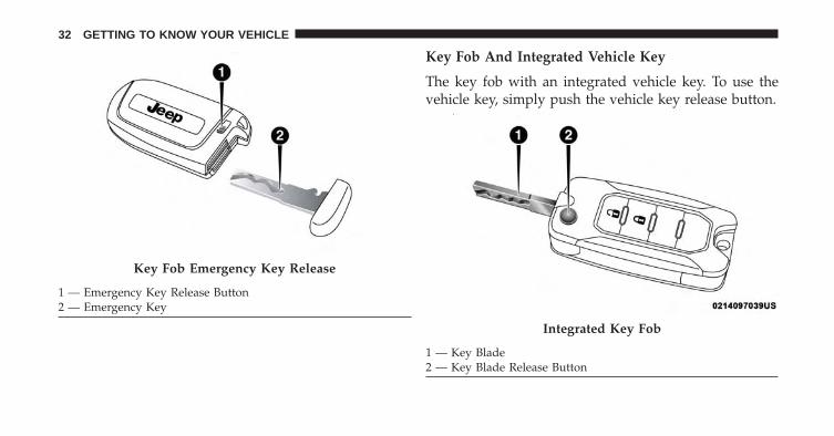
Key Fob And Integrated Vehicle Key
The key fob with an integrated vehicle key. To use thevehicle key, simply push the vehicle key release button.
Key Fob Emergency Key Release
1 — Emergency Key Release Button2 — Emergency Key
Integrated Key Fob
1 — Key Blade2 — Key Blade Release Button
32 GETTING TO KNOW YOUR VEHICLE

General Information
The following regulatory statement applies to all RadioFrequency (RF) devices equipped in this vehicle:
This device complies with Part 15 of the FCC Rules andwith Industry Canada license-exempt RSS standard(s).Operation is subject to the following two conditions:
1. This device may not cause harmful interference, and
2. This device must accept any interference received,including interference that may cause undesired op-eration.
NOTE: Changes or modifications not expressly approvedby the party responsible for compliance could void theuser’s authority to operate the equipment.
To Unlock The Doors And Liftgate
The driver’s door may be unlocked by inserting thevehicle key into the exterior driver’s door lock cylinder.To unlock all the doors, push the interior door unlockbutton on the door panel.
Push and release the UNLOCK button on the key fobonce to unlock the driver’s door or twice within fiveseconds to unlock all doors and the liftgate. The turnsignal lights will flash to acknowledge the unlock signal.The illuminated entry system will also turn on.
1st Push Of Key Fob Unlocks
This feature lets you program the system to unlock eitherthe driver’s door or all doors on the first push of theUNLOCK button on the key fob. To change the currentsetting, refer to “Uconnect SETTINGS” in “Multimedia”for further information.
4
GETTING TO KNOW YOUR VEHICLE 33

NOTE: If the vehicle is equipped with Passive Entry,refer to “Keyless Enter-N-Go” in “Getting To Know YourVehicle” for further information.
To Lock The Doors And Liftgate
If equipped, the doors may be locked by inserting thevehicle key into the exterior driver’s door lock cylinder.
Push and release the LOCK button on the key fob tolock all doors and liftgate. The turn signal lights willflash and the horn will chirp to acknowledge thesignal. Settings in radio can change to lights only,chirp only, or both.
If the vehicle is equipped with Passive Entry, refer to“Keyless Enter-N-Go — Passive Entry” in “Getting ToKnow Your Vehicle” for further information.
Key Fob And Integrated Vehicle Key
If one or more doors are open, or the liftgate is open, thedoors will lock. This is signaled by a quick flash of theturn signals.
Key Fob
If one or more doors are open, or the liftgate is open, thedoors will lock. The doors will unlock again only if thekey is inside the passenger compartment.
NOTE:
• The current setting can be changed within the Elec-tronic Vehicle Information Center (EVIC) menu or inthe Uconnect Settings so that the system will allow/inhibit the ability to lock the doors when one or moreof them are open.
34 GETTING TO KNOW YOUR VEHICLE

• For more information, refer to “Electronic VehicleInformation Center (EVIC)/ Driver Information Dis-play (DID)” in “Getting To Know Your InstrumentCluster” or “Uconnect Settings” in “Multimedia.”
Replacing The Battery In The Key Fob
The recommended replacement battery is one CR2032battery.
NOTE:
• Perchlorate Material — special handling may apply.See www.dtsc.ca.gov/hazardouswaste/perchlorate
• Do not touch the battery terminals that are on the backhousing or the printed circuit board.
Key Fob
1. Separating key fob halves requires screw removal (ifequipped) and gently prying the two halves of the keyfob apart using a screwdriver or similar tool. Makesure not to damage the seal during removal.
1 — Integrated Key Fob
4
GETTING TO KNOW YOUR VEHICLE 35

2. Remove the battery by turning the back cover over(battery facing downward) and tapping it lightly on asolid surface such as a table or similar surface. Then,replace the battery.
When replacing the battery, match the + sign on thebattery to the + sign on the inside of the battery clip,located on the back cover. Avoid touching the newbattery with your fingers. Skin oils may cause batterydeterioration. If you touch a battery, clean it with rubbingalcohol.
2 — Integrated Key Battery Removal
36 GETTING TO KNOW YOUR VEHICLE

Separating Key Fob Case
1. Remove the emergency key by sliding the mechanicallatch on the back of the key fob sideways with yourthumb. Then, pull the key out with your other hand.
2. Separating key fob halves requires screw removal (ifequipped) and gently prying the two halves of the keyfob apart with the emergency key. Make sure not todamage the seal during removal.
1 — Separating The Key Fob Case
4
GETTING TO KNOW YOUR VEHICLE 37

3. Remove the battery by turning the back cover over(battery facing downward) and tapping it lightly on asolid surface such as a table or similar surface. Then,replace the battery.
When replacing the battery, match the + sign on thebattery to the + sign on the inside of the battery clip,located on the back cover. Avoid touching the newbattery with your fingers. Skin oils may cause batterydeterioration. If you touch a battery, clean it with rubbingalcohol.
4. To assemble the key fob case, snap the two halvestogether and insert the emergency key.
1 — Key Fob Battery Replacement
38 GETTING TO KNOW YOUR VEHICLE

Programming Additional Key Fobs
Programming key fobs may be performed at an autho-rized dealer.
Request For Additional Key Fobs
NOTE: Only key fobs that are programmed to the ve-hicle electronics can be used to start and operate thevehicle. Once a key fob is programmed to a vehicle, itcannot be programmed to any other vehicle.
CAUTION!
• Always remove the key fobs from the vehicle andlock all doors when leaving the vehicle unat-tended.
• For vehicles equipped with Keyless Enter-N-Go —Ignition, always remember to place the ignition inthe OFF mode.
At the time of purchase, the original owner is providedwith a four-digit Personal Identification Number (PIN).Keep the PIN in a secure location. This number isrequired for authorized dealer replacement of key fobs.Duplication of key fobs may be performed at an autho-rized dealer. This procedure consists of programming ablank key fob to the vehicle electronics. A blank key fobis one that has never been programmed.
NOTE: When having the Sentry Key Immobilizer Systemserviced, bring all vehicle keys with you to an authorizeddealer.
4
GETTING TO KNOW YOUR VEHICLE 39

IGNITION SWITCH
Operation
Your vehicle uses either a key start ignition system orkeyless ignition system. The key start ignition systemconsists of a key fob with a Remote Keyless Entry key foband an Ignition Node Module (IGNM). The keylessignition system consists of a key fob with Keyless PushButton Ignition.
Models With Integrated Vehicle Key
The Ignition Node Module (IGNM) operates similar to anignition switch. It has three operating positions, two withdetents and one that is spring-loaded. The detent posi-tions are STOP/OFF, MAR/RUN, and AVV/START. TheAVV/START position is a spring-loaded momentarycontact position. When released from the AVV/STARTposition, the switch automatically returns to the MAR/RUN position.
1 — STOP/OFF
• The engine is stopped.
• The key can be removed from the IGNM.
• The steering column can be locked (with the ignitionkey removed).
Ignition Node Module (IGNM)
40 GETTING TO KNOW YOUR VEHICLE

• Some electrical devices (e.g. power locks, alarm, etc.)are still available.
2 — MAR/RUN
• Driving position.
• Electrical devices are available.
3 — AVV/START
• Start the engine.
The ignition switch is provided with a safety mechanism.If the engine fails to start, the ignition should be returnedto the STOP/OFF position prior to repeating the startingprocedure.
On models equipped with an automatic transmission, theignition key is only removable when the gear selector isin PARK (P).
NOTE: Ensure mechanical key is cycled to the STOP/OFF position. There may be a one second delay beforebeing able to remove the mechanical key from theignition.
Models With Keyless Enter-N-Go
This feature allows the driver to operate the ignitionswitch with the push of a button as long as the key fob isin the passenger compartment.
The Keyless Push Button Ignition has three operatingpositions. The three positions are STOP, RUN, andSTART.
4
GETTING TO KNOW YOUR VEHICLE 41

NOTE: If the ignition switch does not change with thepush of a button, the key fob may have a low or deadbattery. In this situation, a back up method can be used tooperate the ignition switch. Put the nose side (sideopposite of the emergency key) of the key fob against theENGINE START/STOP button and push to operate theignition switch.
START/STOP Button
42 GETTING TO KNOW YOUR VEHICLE

The Keyless Push Button Ignition can be placed in thefollowing positions:
STOP
• The engine is stopped.
• Some electrical devices (e.g. Central locking, alarm,etc.) are still available.
RUN
• Driving position.
• All the electrical devices are available.
START
• Start the engine.
NOTE: The vehicle will not start if the FOBIK (key fob) islocated inside the cargo area and the liftgate is opened.
WARNING!
• When leaving the vehicle, always remove the keyfob from the vehicle and lock your vehicle.
• Never leave children alone in a vehicle, or withaccess to an unlocked vehicle.
• Allowing children to be in a vehicle unattended isdangerous for a number of reasons. A child orothers could be seriously or fatally injured. Chil-dren should be warned not to touch the parkingbrake, brake pedal or the gear selector.
• Do not leave the key fob in or near the vehicle, orin a location accessible to children, and do notleave the ignition of a vehicle equipped withKeyless Enter-N-Go in the MAR/RUN mode. Achild could operate power windows, other controls,or move the vehicle.
(Continued)
4
GETTING TO KNOW YOUR VEHICLE 43

WARNING! (Continued)• Do not leave children or animals inside parked
vehicles in hot weather. Interior heat build-up maycause serious injury or death.
CAUTION!
An unlocked car is an invitation. Always remove thekey from the ignition and lock all doors whenleaving the vehicle unattended.
NOTE: For further information, refer to �Starting theEngine,� in �Starting And Operating.�
General Information
The following regulatory statement applies to all RadioFrequency (RF) devices equipped in this vehicle:
This device complies with Part 15 of the FCC Rules andwith Industry Canada license-exempt RSS standard(s).Operation is subject to the following two conditions:
1. This device may not cause harmful interference, and
2. This device must accept any interference received,including interference that may cause undesired op-eration.
NOTE: Changes or modifications not expressly approvedby the party responsible for compliance could void theuser’s authority to operate the equipment.
44 GETTING TO KNOW YOUR VEHICLE

REMOTE STARTING SYSTEM — IF EQUIPPED
This system uses the key fob to start the engineconveniently from outside the vehicle whilestill maintaining security. The system has arange of 328 ft (100 m).
The Remote Starting System also activates the ClimateControl and (if equipped) the optional heated seats andoptional heated steering wheel depending on tempera-tures outside and inside the car.
NOTE:
• The vehicle must be equipped with an automatictransmission to be equipped with Remote Start.
• Obstructions between the vehicle and key fob mayreduce this range.
Remote Start Cancel Message — If Equipped
The following messages will display in the instrumentcluster if the vehicle fails to remote start or exits remotestart prematurely:
• Remote Start Cancelled — Door Open
• Remote Start Cancelled — Hood Open
• Remote Start Cancelled — Fuel Low
• Remote Start Cancelled — Liftgate Open
• Remote Start Disabled — Start Vehicle To Reset
• Remote Start Cancelled — Too Cold
• Remote Start Cancelled — Time Expired
The message will stay active until the ignition is placed inthe MAR/RUN position.
4
GETTING TO KNOW YOUR VEHICLE 45

How To Use Remote Start
All of the following conditions must be met before theengine will remote start:
• Gear Selector in PARK
• Doors closed
• Hood closed
• Liftgate closed
• Hazard switch off
• Brake switch inactive (brake pedal not pushed)
• Battery at an acceptable charge level
• PANIC button not pushed
• System not disabled from previous remote start event
• Vehicle alarm system indicator flashing
• Ignition in STOP/OFF position
• Fuel level meets minimum requirement
• Vehicle Security Alarm is not signaling an intrusion
WARNING!
• Do not start or run an engine in a closed garage orconfined area. Exhaust gas contains Carbon Mon-oxide (CO) which is odorless and colorless. CarbonMonoxide is poisonous and can cause serious in-jury or death when inhaled.
• Keep key fobs away from children. Operation ofthe Remote Start System, windows, door locks orother controls could cause serious injury or death.
46 GETTING TO KNOW YOUR VEHICLE

To Enter Remote Start Mode
Push and release the REMOTE START buttonon the key fob twice within five seconds. Thevehicle doors will lock, the turn signals willflash, and the horn will chirp twice. Then, the
engine will start, and the vehicle will remain in theRemote Start mode for a 15-minute cycle.
NOTE:
• If an engine fault is present or fuel level is low, thevehicle will start and then shut down in 10 seconds.
• The park lamps will turn on and remain on duringRemote Start mode.
• For security, power window operation is disabledwhen the vehicle is in the Remote Start mode.
To Exit Remote Start Mode Without Driving TheVehicle
Push and release the REMOTE START button onetime or allow the engine to run for the entire 15-minute cycle.
NOTE: To avoid unintentional shutdowns, the systemwill disable with a one time push of the REMOTE START
button for two seconds after receiving a validRemote Start request.
To Exit Remote Start Mode And Drive The Vehicle
Before the end of 15-minute cycle, push and release theUNLOCK button on the key fob to unlock the doorsand disarm the Vehicle Security Alarm (if equipped).Then, prior to the end of the 15-minute cycle, forvehicles equipped with the Keyless Enter-N-Go fea-ture push and release the keyless ignition button;for vehicles not equipped with Keyless Enter-N-Gofeature put the key in RUN position.
4
GETTING TO KNOW YOUR VEHICLE 47

NOTE: For vehicles equipped with the Keyless Enter-N-Go feature, the message “Remote Start Active — PushStart Button” will display in the Electronic Vehicle Infor-mation Center (EVIC) or the Driver Information Display(DID) until you push the keyless ignition button.
NOTE: For vehicles not equipped with the KeylessEnter-N-Go feature, the message “Remote Start Active —Key to RUN” will display in the Electronic VehicleInformation Center (EVIC) until you put the key in RUNposition.
Remote Start Comfort Systems — If Equipped
When Remote Start is activated, the heated steeringwheel and driver heated seat features will automaticallyturn on in cold weather. These features will stay onthrough the duration of Remote Start or until the ignitionswitch is cycled to the MAR/RUN position.
NOTE: The Remote Start Comfort System can be acti-vated and deactivated through the Uconnect Settings. Formore information on Remote Start Comfort System op-eration, refer to “Uconnect Settings” in “Multimedia.”
Remote Start Windshield Wiper De–IcerActivation — If Equipped
When Remote Start is active and the outside ambienttemperature is less than 40° F (4.4° C), the WindshieldWiper De-Icer will be enabled. Exiting Remote Start willresume previous operation, except if the WindshieldWiper De-Icer is active. The Windshield Wiper De-Icertimer and operation will continue.
48 GETTING TO KNOW YOUR VEHICLE

General Information
The following regulatory statement applies to all RadioFrequency (RF) devices equipped in this vehicle:
This device complies with Part 15 of the FCC Rules andwith Industry Canada license-exempt RSS standard(s).Operation is subject to the following two conditions:
1. This device may not cause harmful interference, and
2. This device must accept any interference received,including interference that may cause undesired op-eration.
NOTE: Changes or modifications not expressly approvedby the party responsible for compliance could void theuser’s authority to operate the equipment.
SENTRY KEY
The Sentry Key Immobilizer system prevents unauthor-ized vehicle operation by disabling the engine. Thesystem does not need to be armed or activated. Operationis automatic, regardless of whether the vehicle is lockedor unlocked.
The system uses a key fob with a Keyless Push ButtonIgnition, and a RF receiver to prevent unauthorizedvehicle operation. Therefore, only key fobs that areprogrammed to the vehicle can be used to start andoperate the vehicle. The system will not allow the engineto crank if an invalid key fob tries to start the engine.
After placing the ignition to the ON/RUN position, ifthere is a problem with the system, the Vehicle SecurityLight will turn on. This condition will result in the enginebeing shut off after two seconds.
4
GETTING TO KNOW YOUR VEHICLE 49

Should this occur, have the vehicle serviced as soon aspossible by an authorized dealer.
CAUTION!
• Do not make modifications or alterations to theimmobilizer system. Modifications or alterations tothe immobilization system may result in a loss ofsecurity protection.
• The Sentry Key Immobilizer system is not compat-ible with some aftermarket remote starting sys-tems. Use of these systems may result in vehiclestarting problems and loss of security protection.
General Information
The following regulatory statement applies to all radiofrequency (RF) devices equipped in this vehicle:
This device complies with Part 15 of the FCC Rules andwith Industry Canada license-exempt RSS standard(s).Operation is subject to the following two conditions:
1. This device may not cause harmful interference, and
2. This device must accept any interference received,including interference that may cause undesired op-eration.
NOTE: Changes or modifications not expressly approvedby the party responsible for compliance could void theuser’s authority to operate the equipment.
50 GETTING TO KNOW YOUR VEHICLE

VEHICLE SECURITY ALARM
The Vehicle Security Alarm monitors the vehicle doorsfor unauthorized entry and if the ignition switch is cycledto the ON/RUN position without a valid key. While theVehicle Security Alarm is armed, interior switches fordoor locks and liftgate release are disabled.
If something triggers the alarm, the Vehicle SecurityAlarm will provide the following audible and visiblesignals:
• Horn will pulse.
• Park lamps and/or turn signals will flash.
• Vehicle Security Light in the instrument cluster willflash.
1 — Vehicle Security Light
4
GETTING TO KNOW YOUR VEHICLE 51

To Arm The System
Follow these steps to arm the Vehicle Security Alarm:
1. Make sure the keyless ignition is placed in the STOP/OFF position (refer to �Starting The Engine� in �Start-ing And Operating� for further information).• For vehicles equipped with Keyless Enter-N-Go —
Ignition, make sure the vehicle ignition system is OFF.• For vehicles not equipped with Keyless Enter-N-Go
— Ignition, make sure the keyless ignition system isSTOP/OFF, and the key fob is physically removedfrom the vehicle.
2. Perform one of the following methods to lock the vehicle:
• Push the LOCK button on the interior powerdoor lock switch with the driver and/or passen-ger door open.
• Push the LOCK button on the exterior PassiveEntry Door Handle with a valid key fob available
in the same exterior zone (for further information,refer to �Keyless Enter-N-Go� in �Getting To KnowYour Vehicle”).
• Push the LOCK button on the key fob.
3. If any doors are open, close them.
NOTE:
• If a second chime is heard after approximately fourseconds from arming the alarm, disarm the alarm bypressing the UNLOCK button. Check for the correctclosure of doors and liftgate, then reactivate thesystem by following steps 1 and 2.
• If a second chime is heard after approximately fourseconds from arming the alarm, even with the doorsand liftgate properly closed, a fault may have oc-curred during the arming operation. If this occurs,contact your authorized dealer.
52 GETTING TO KNOW YOUR VEHICLE

To Disarm The System
The Vehicle Security Alarm can be disarmed using any ofthe following methods:
• Push the UNLOCK button on the key fob.
• Grasp the Passive Entry Unlock Door Handle with avalid key fob available in the same exterior zone (ifequipped). Refer to �Keyless Enter-N-Go� in �GettingTo Know Your Vehicle� for further information.
• Cycle the vehicle ignition system out of the STOP/OFFposition.– For vehicles equipped with Keyless Enter-N-Go,
push the Keyless Enter-N-Go START/STOP button(requires at least one valid key fob in the vehicle).
– For vehicles not equipped with Keyless Enter-N-Go,insert a valid key into the ignition switch and turnthe key to the MAR/RUN position.
NOTE:
• The driver’s door key cylinder cannot arm or disarmthe Vehicle Security Alarm.
• When the Vehicle Security Alarm is armed, the interiorpower door lock switches will not unlock the doors.
The Vehicle Security Alarm is designed to protect yourvehicle. However, you can create conditions where thesystem will give you a false alarm. If one of the previ-ously described arming sequences has occurred, theVehicle Security Alarm will arm regardless of whetheryou are in the vehicle or not. If you remain in the vehicleand open a door, the alarm will sound. If this occurs,disarm the Vehicle Security Alarm.
If the Vehicle Security Alarm is armed and the batterybecomes disconnected, the Vehicle Security Alarm willremain armed when the battery is reconnected.
4
GETTING TO KNOW YOUR VEHICLE 53

Disabling
To completely disable the alarm (e.g. in the case of longinactivity of the car), lock the doors by turning the vehiclekey in the exterior door lock cylinder.
NOTE: If the batteries in the key fob discharge in theevent of a failure to the system, or to switch off the alarm,place the ignition in the MAR/RUN position.
DOORS
Manual Door Locks
To lock each door, rotate the door lock button on eachdoor trim panel forward. To unlock the doors, pull theinside door handle to the first detent or rotate the doorlock button until the lock symbol is no longer visible.
If the lock symbol is visible when the door is shut, thedoor will lock. Therefore, make sure the key fob is notinside the vehicle before closing the door.
Locking/Unlocking Doors From Outside
With the doors closed, insert the key blade into the driverexterior door lock cylinder and turn to the right to lockthe driver’s door.
To unlock the driver’s door, insert the key blade into thedriver exterior door lock cylinder and turn to the left tounlock the driver’s door.
54 GETTING TO KNOW YOUR VEHICLE

NOTE: The manual lock knob unlocks each individualdoor separately.
WARNING!
• For personal security and safety in the event of acollision, lock the vehicle doors before you drive aswell as when you park and leave the vehicle.
• When leaving the vehicle, always remove the keyfob from the vehicle and lock your vehicle. Unsu-pervised use of vehicle equipment may cause se-vere personal injuries or death.
• Never leave children alone in a vehicle, or withaccess to an unlocked vehicle. Allowing children tobe in a vehicle unattended is dangerous for anumber of reasons. A child or others could beseriously or fatally injured. Children should bewarned not to touch the parking brake, brake pedalor the gear selector.
(Continued)
Manual Door Lock
4
GETTING TO KNOW YOUR VEHICLE 55

WARNING! (Continued)• Do not leave the key fob in or near the vehicle, or
in a location accessible to children, and do notleave the ignition of a vehicle equipped withKeyless Enter-N-Go in the RUN mode. A childcould operate power windows, other controls, ormove the vehicle.
Central Lock/Unlock
A power door lock switch is located on each ofthe front door trim panels. This switch is used to lockor unlock the doors and liftgate.
Locking/Unlocking From The Inside
Push the LOCK button on the driver or passengerdoor trim panel to lock the doors.
With the doors locked, push the button to unlock thedoors.
The doors can also be locked and unlocked with theKeyless Enter-N-Go — Passive Entry system if equipped.Refer to “Keyless Enter-N-Go — Passive Entry” in “Get-ting To Know Your Vehicle” for further information.
Power Door Lock Switch
56 GETTING TO KNOW YOUR VEHICLE

The power locks will continue to operate while theignition is in the MAR/RUN and STOP/OFF position. Ifa door is open, and the ignition is in the MAR/RUNposition, a chime will sound as a reminder to remove thekey.
NOTE: If all of the doors are closed properly, the doorlocks will lock automatically when the vehicle’s speedexceeds 12 MPH (20 km/h). Refer to “Uconnect SET-TINGS” in “Multimedia” for further information.
Keyless Enter-N-Go — Passive Entry
The Passive Entry system is an enhancement to thevehicle’s Remote Keyless Entry system and a feature ofKeyless Enter-N-Go. This feature allows you to lock andunlock the vehicle’s door(s) without having to push thekey fob LOCK or UNLOCK buttons.
NOTE:
• Passive Entry can be enabled or disabled. Refer to“Uconnect SETTINGS” in “Multimedia” for furtherinformation.
• If wearing gloves on your hands, or if it has beenraining on the Passive Entry door handle, the unlocksensitivity can be affected, resulting in a slower re-sponse time.
• If the vehicle is unlocked by the Passive Entry DoorHandle, and no door is opened within 60 seconds, thevehicle will re-lock and if equipped, the security alarmwill arm.
4
GETTING TO KNOW YOUR VEHICLE 57

To Unlock From The Driver’s Side
With a valid Passive Entry key fob within 5 ft (1.5 m) ofthe driver’s door handle, grab the front driver doorhandle to unlock the driver’s door automatically.
NOTE: If “Unlock All Doors 1st Press” is programmed,all doors will unlock when you grab hold of the frontdriver’s door handle. To select between “Unlock DriverDoor 1st Press” and “Unlock All Doors 1st Press,” refer to“Uconnect SETTINGS” in “Multimedia” for further in-formation.
To Unlock From The Passenger Side
With a valid Passive Entry key fob within 5 ft (1.5 m) ofthe passenger door handle, grab the front passenger doorhandle to unlock all four doors and the liftgate automati-cally.
NOTE: All doors will unlock when the front passengerdoor handle is grabbed regardless of the driver’s doorunlock preference setting (“Unlock Driver Door 1stPress” or “Unlock All Doors 1st Press”).
Grab The Door Handle To Unlock
58 GETTING TO KNOW YOUR VEHICLE

To Lock The Vehicle’s Doors And Liftgate
With one of the vehicle’s Passive Entry key fobs within 5ft (1.5 m) of the driver or passenger front door handles,push the door handle LOCK button to lock all four doors.
Do NOT grab the door handle when pushing the doorhandle LOCK button. This could unlock the door(s).
NOTE: The Passive Entry system will not operate if thekey fob battery is dead.
The vehicle doors can also be locked by using the lockbutton located on the vehicle’s interior door panel.
Push The Door Handle Button To Lock
DO NOT Grab The Door Handle When Locking
4
GETTING TO KNOW YOUR VEHICLE 59

Preventing Inadvertent Locking Of Passive Entry keyfob In Vehicle (FOBIK-Safe)
To minimize the possibility of unintentionally locking aPassive Entry key fob inside your vehicle, the PassiveEntry system is equipped with an automatic door unlockfeature which will function if the ignition switch is in theOFF position.
FOBIK-Safe only executes in vehicles with Passive Entry.There are three situations that trigger a FOBIK-Safesearch in any Passive Entry vehicle:
1. A lock request is made by a valid Passive Entry keyfob while a door is open.
2. A lock request is made by the Passive Entry doorhandle while a door is open.
3. A lock request is made by the door panel switch whilethe door is open.
When any of these situations occur, after all open doorsare shut, the FOBIK-Safe search will be executed. If itfinds a Passive Entry key fob inside the car, and it doesnot find any Passive Entry key fobs outside the car, thenthe car will unlock and alert the customer.
NOTE: The vehicle will only unlock the doors when avalid Passive Entry key fob is detected inside the vehicle,and no valid Passive Entry key fob is detected outside thevehicle. The vehicle will not unlock the doors when anyof the following conditions are met:
• The doors are manually locked using the door lockknobs.
• There is a valid Passive Entry key fob outside thevehicle and within 5 ft (1.5 m) of either Passive Entrydoor handle.
60 GETTING TO KNOW YOUR VEHICLE

To Unlock/Enter The Liftgate
The liftgate Passive Entry unlock feature is built into theelectronic liftgate release. With a valid Passive Entry keyfob within 5 ft (1.5 m) of the liftgate, push the ElectronicLiftgate release to open with one fluid motion.
To Lock The Liftgate
With a valid Passive Entry key fob within 5 ft (1.5 m) ofthe liftgate, push the Passive Entry LOCK button locatedto the right of electronic liftgate release.
NOTE: The liftgate Passive Entry lock button will lockthe liftgate and the doors. The liftgate unlock feature isbuilt into the Electronic Liftgate release.
Liftgate Release/Passive Entry
1 — Electronic Liftgate Release/Liftgate Passive Entry Location2 — Electronic Liftgate Lock/Liftgate Passive Lock Location
4
GETTING TO KNOW YOUR VEHICLE 61

NOTE: If “Unlock All Doors 1st Press” is programmed inEVIC/DID, if equipped, only the liftgate will unlockwhen you push the Electronic Release. If �Unlock DriverDoor 1st Press� is programmed in Uconnect, the liftgatewill unlock when you push the electronic unlock/lockbutton on the liftgate. For further information, refer to“Uconnect SETTINGS” in “Multimedia.”
Emergency Unlocking Driver Door
If the key fob battery is low or dead, the emergency keycan be used to unlock the driver side door lock cylinder.
To release the emergency key, proceed as follows:
1. Slide the emergency key release button to the side.
2. Remove the emergency key from the key fob withRemote Control housing.
NOTE: The Emergency Key can be inserted into the doorlock cylinder from either direction.
Emergency Key Release
1 — Emergency Key Release Button2 — Emergency Key
62 GETTING TO KNOW YOUR VEHICLE

WARNING!
• Never leave children alone in a vehicle, or withaccess to an unlocked vehicle. Allowing children tobe in a vehicle unattended is dangerous for anumber of reasons. A child or others could beseverely injured or killed. Children should bewarned not to touch the parking brake, brakepedal, or the gear selector. Do not leave the key fobin or near the vehicle, or in a location accessible tochildren, and do not leave the ignition of a vehicleequipped with Keyless Enter- N-Go in the MAR/RUN mode. A child could start the vehicle, operatepower windows, other controls, or move the ve-hicle.
• Do not leave children or animals inside parkedvehicles in hot weather. Interior heat build-up maycause them to be severely injured or killed.
General Information
The following regulatory statement applies to all radiofrequency (RF) devices equipped in this vehicle:
This device complies with Part 15 of the FCC Rules andwith Industry Canada licence-exempt RSS standard(s).Operation is subject to the following two conditions:
1. This device may not cause harmful interference, and
2. This device must accept any interference received,including interference that may cause undesired op-eration.
NOTE: Changes or modifications not expressly approvedby the party responsible for compliance could void theuser’s authority to operate the equipment.
4
GETTING TO KNOW YOUR VEHICLE 63

Child Locks
To provide a safer environment for small children ridingin the rear seats, the rear doors are equipped with aChild-Protection Door Lock system.
To use the system, open each rear door, use a flat bladescrewdriver (or ignition key) and rotate the dial to theLOCK or UNLOCK position. When the system on a dooris engaged, that door can only be opened by using theoutside door handle even if the inside door lock is in theunlocked position.
NOTE:
• When the child lock system is engaged, the door canonly be opened by using the outside door handle eventhough the inside door lock is in the unlocked position.
Child-Protection Door Lock Location
64 GETTING TO KNOW YOUR VEHICLE

• After disengaging the Child-Protection Door Locksystem, always test the door from the inside to makecertain it is in the desired position.
• After engaging the Child-Protection Door Lock sys-tem, always test the door from the inside to makecertain it is in the desired position.
• For emergency exit with the system engaged, rotatethe lock/unlock dial to the unlocked position, rolldown the window, and open the door with the outsidedoor handle.
WARNING!
Avoid trapping anyone in a vehicle in a collision.Remember that the rear doors can only be openedfrom the outside when the Child-Protection locks areengaged.
SEATS
Seats are a part of the Occupant Restraint System of thevehicle.
WARNING!
• It is dangerous to ride in a cargo area, inside oroutside of a vehicle. In a collision, people riding inthese areas are more likely to be seriously injuredor killed.
• Do not allow people to ride in any area of yourvehicle that is not equipped with seats and seatbelts. In a collision, people riding in these areas aremore likely to be seriously injured or killed.
• Be sure everyone in your vehicle is in a seat andusing a seat belt properly.
4
GETTING TO KNOW YOUR VEHICLE 65

Manual Front Seats
Manual Front Seat Forward/Rearward AdjustmentOn models equipped with manual seats, the adjustingbar is located at the front of the seats, near the floor.
While sitting in the seat, lift up on the bar and move theseat forward or rearward. Release the bar once you havereached the desired position. Then, using body pressure,move forward and rearward on the seat to be sure thatthe seat adjusters have latched.
WARNING!
• Adjusting a seat while the vehicle is moving isdangerous. The sudden movement of the seat couldcause you to lose control. The seat belt might not beadjusted properly and you could be injured. Adjustthe seat only while the vehicle is parked.
• Do not ride with the seatback reclined so that theshoulder belt is no longer resting against yourchest. In a collision you could slide under the seatbelt and be seriously or even fatally injured. Usethe recliner only when the vehicle is parked.
Manual Seat Adjustment Levers1 — Forward/Rearward Adjustment Bar2 — Seat Height Adjustment Lever3 — Recline Lever
66 GETTING TO KNOW YOUR VEHICLE

Height Adjustment
The driver’s seat height can be raised or lowered byusing a lever, located on the outboard side of the seat.Pull upward on the lever to raise the seat height or pushdownward on the lever to lower the seat height.
Recline Adjustment
To adjust the seatback, lift the lever located on theoutboard side of the seat, lean back to the desiredposition and release the lever. To return the seatback, liftthe lever, lean forward and release the lever.
Power Adjustment (Front) — If Equipped
The power seat controls are located on the outboard sideof the seat, close to the floor.
Use the switch to move the seat up/down, forward/rearward, tilt if equipped and to set the angle of the seatback.
Power Seat Switches
1 — Power Seat Switch2 — Power Recline Switch3 — Power Lumbar Switch
4
GETTING TO KNOW YOUR VEHICLE 67

Forward Or Rearward Adjustment
The seat can be adjusted both forward and rearward.Push the seat switch forward or rearward, the seat willmove in the direction of the switch. Release the switchwhen the desired position has been reached.
Height Adjustment
The height of the seats can be adjusted up or down. Pullupward or push downward on the seat switch, the seatwill move in the direction of the switch. Release theswitch when the desired position is reached.
Recline Adjustment
Push the seat recliner switch forward or rearward, theseatback will move in the direction of the switch. Releasethe switch when the desired position has been reached.
Tilt Adjustment
The angle of the seat cushion can be adjusted up ordown. Pull upward or push downward on the front ofthe seat switch, the front of the seat cushion will move inthe direction of the switch.
Power Lumbar Adjustment
Push the switch forward or rearward to increase ordecrease the lumbar support. Push the switch upward ordownward to raise or lower the lumbar support.
Heated Seats — If Equipped
The heated seat switches are located on the instrumentpanel.
You can choose between two heating levels:
• Push the heated seat button once to turn the HIsetting ON.
68 GETTING TO KNOW YOUR VEHICLE

• Push the heated seat button a second time to turnthe LO setting ON.
• Push the heated seat button a third time to turnthe heating elements OFF.
If the HI-level setting is selected, the system will auto-matically switch to LO-level after approximately 145minutes of continuous operation. At that time, the dis-play will change from HI to LO, indicating the change.The LO-level setting will turn OFF automatically afterapproximately 60 minutes.
NOTE: The engine must be running for the heated seatsto operate.
Auto Comfort Systems — If Equipped
In vehicles equipped with Auto on Comfort, when turningon the vehicle the driver’s heated seat will automaticallyturn ON when temperatures are below 40° F (4.4° C).
WARNING!
• Persons who are unable to feel pain to the skinbecause of advanced age, chronic illness, diabetes,spinal cord injury, medication, alcohol use, exhaus-tion or other physical condition must exercise carewhen using the seat heater. It may cause burnseven at low temperatures, especially if used forlong periods of time.
• Do not place anything on the seat or seatback thatinsulates against heat, such as a blanket or cushion.This may cause the seat heater to overheat. Sittingin a seat that has been overheated could causeserious burns due to the increased surface tempera-ture of the seat.
4
GETTING TO KNOW YOUR VEHICLE 69

Rear Seats
The split rear seat has the ability to fold flat whichincreases the storage of the rear cargo area.
NOTE:
• Prior to folding the rear seat down, it may be necessaryto position the front seat to its mid-track position. Besure that the front seats are fully upright and posi-tioned forward, this will allow the rear seat to folddown easily.
• Prior to folding the rear seat, you must secure the reararmrest in up position.
• You may experience deformation in the seat cushionfrom the seat belt buckles if the seats are left folded foran extended period of time. This is normal and bysimply opening the seats to the open position, overtime the seat cushion will return to its normal shape.
WARNING!
• It is extremely dangerous to ride in a cargo area,inside or outside of a vehicle. In a collision, peopleriding in these areas are more likely to be seriouslyinjured or killed.
• Do not allow people to ride in any area of yourvehicle that is not equipped with seats and seatbelts.
• Be sure everyone in your vehicle is in a seat andusing a seat belt properly.
70 GETTING TO KNOW YOUR VEHICLE

Removing Shelf — If Equipped
Proceed as follows:
1. Disconnect the two links that support the shelf at theeyelets.
2. Lift the rear part of the overhead luggage shelf.
3. Clear the pins placed outside of the shelf, and thenremove the rear shelf pulling it upwards.
Rear Shelf Support Links
1 — Links2 — Eyelets
4
GETTING TO KNOW YOUR VEHICLE 71

4. The rear shelf can be stored in the cargo area, orbehind the front seatbacks.
Adjusting The Rear Shelf
Rear Shelf Pin
72 GETTING TO KNOW YOUR VEHICLE

Partial Enlargement Of Cargo Area
Enlargement of the left side of the cargo area allows youto carry a single passenger on the right side of the rearseat, while the enlargement of the right side allows you tocarry two passengers.
Proceed as follows:
1. Remove the rear shelf (if equipped).
2. Fully lower the rear seat head restraints.
3. Move the safety belts to the outboard side of the seatand rest them on the seat belt guide.
4. Pull the seatback release lever to fold the left or rightrear seatback completely forward.
Rear Seat Release
1 — Seatback Release Lever2 — Seat Belt Guide
4
GETTING TO KNOW YOUR VEHICLE 73

Cargo Area Enlargement
Folding both sides of the rear seat provides additionalstorage in the rear cargo area.
Proceed as follows:
1. Fully lower the rear seat head restraints.
2. Move the safety belts to the outboard side of the seat.
3. Pull the seatback release lever to fold both sides of therear seatbacks completely forward.
Seatback Repositioning
NOTE: If interference from the cargo area prevents theseatback from fully locking, you will have difficultyreturning the seat to its proper position.
1. Move the safety belts to the seat belt guides on the topedge of the seat to ensure the seatbacks properly latch.
2. Lift the seatbacks, pushing them back until they lockon both the latches. Verify the red notches are nolonger visible on the release lever. If the red notchesare visible, the seatback is not secure.
Rear Seat Latch
74 GETTING TO KNOW YOUR VEHICLE

Unfolding The Rear Armrest 40/20/40
Tilt the head restraint forward and pull the rear armresttab to release it from the seat and pull forward.
The center part of the rear seat can also be used as reararmrest with cupholders.
Rear Seat Center Armrest — If Equipped
Rear Armrest
4
GETTING TO KNOW YOUR VEHICLE 75
WARNING!
Be certain that the seatback is securely locked intoposition. If the seatback is not securely locked intoposition the seat will not provide the proper stabilityfor child seats and/or passengers. An improperlylatched seat could cause serious injury.
HEAD RESTRAINTS
Head restraints are designed to reduce the risk of injuryby restricting head movement in the event of a rearimpact. Head restraints should be adjusted so that the topof the head restraint is located above the top of your ear.
WARNING!
• All occupants, including the driver, should notoperate a vehicle or sit in a vehicle’s seat until thehead restraints are placed in their proper positionsin order to minimize the risk of neck injury in theevent of a crash.
• Head restraints should never be adjusted while thevehicle is in motion. Driving a vehicle with thehead restraints improperly adjusted or removedcould cause serious injury or death in the event ofa collision.
76 GETTING TO KNOW YOUR VEHICLE

Front Head RestraintsYour vehicle is equipped with front driver and passengerhead restraints.To raise the head restraint, pull upward on the headrestraint. To lower the head restraint, push the adjust-ment button, located at the base of the head restraint, andpush downward on the head restraint.
NOTE: The head restraints should only be removed byqualified technicians, for service purposes only. If eitherof the head restraints require removal, see your autho-rized dealer.
WARNING!
• All occupants, including the driver, should notoperate a vehicle or sit in a vehicle’s seat until thehead restraints are placed in their proper positionsin order to minimize the risk of neck injury in theevent of a crash.
• Head restraints should never be adjusted while thevehicle is in motion. Driving a vehicle with thehead restraints improperly adjusted or removedcould cause serious injury or death in the event ofa collision.
Head Restraint Adjustment Button
4
GETTING TO KNOW YOUR VEHICLE 77

Rear Head Restraints
Your vehicle is equipped with 2 outboard head restraintsand 1 center head restraint for its rear passengers. Therear head restraints can be raised or lowered. When thecenter seat is being occupied, the head restraint should bein the raised position. When there are no occupants in thecenter seat, the head restraint can be lowered for maxi-mum visibility for the driver.
To raise the head restraint, pull upward on the headrestraint.
To lower the head restraint, push the adjustment button,located at the base of the head restraint, and pushdownward on the head restraint. NOTE: The head restraints should only be removed by
qualified technicians, for service purposes only. If eitherof the head restraints require removal, see your autho-rized dealer.
Adjustment Button
78 GETTING TO KNOW YOUR VEHICLE

STEERING WHEEL
Tilt/Telescoping Steering Column
This feature allows you to tilt the steering column upward ordownward. It also allows you to lengthen or shorten thesteering column. The tilt/telescoping lever is located belowthe steering wheel at the end of the steering column.
To unlock the steering column, push the tilt/telescopinglever downward (toward the floor). To tilt the steeringcolumn, move the steering wheel upward or downwardas desired. To lengthen or shorten the steering column,pull the steering wheel outward or push it inward asdesired.
To lock the steering column in position, pull the tilt/telescoping lever upward until fully engaged.
WARNING!
Do not adjust the steering column while driving.Adjusting the steering column while driving or driv-ing with the steering column unlocked, could causethe driver to lose control of the vehicle. Failure tofollow this warning may result in serious injury ordeath.
Tilt Steering Wheel Lever
4
GETTING TO KNOW YOUR VEHICLE 79

Heated Steering Wheel — If Equipped
The steering wheel contains a heating element that helpswarm your hands in cold weather. The heated steeringwheel has only one temperature setting. Once the heatedsteering wheel switch has been turned on, it willoperate for up to 100 minutes before automaticallyshutting off. The heated steering wheel can shut offearly or may not turn on when the steering wheel isalready warm. The heated steering wheel controlbutton is located on the center of the instrument panelbelow the radio screen.
Auto Comfort Systems — If Equipped
In vehicles equipped with Auto on Comfort, when turn-ing on the vehicle the heated steering wheel will auto-matically turn ON when temperatures are below 40° F(4.4° C).
WARNING!
• Persons who are unable to feel pain to the skinbecause of advanced age, chronic illness, diabetes,spinal cord injury, medication, alcohol use, exhaus-tion, or other physical conditions must exercisecare when using the steering wheel heater. It maycause burns even at low temperatures, especially ifused for long periods.
• Do not place anything on the steering wheel thatinsulates against heat, such as a blanket or steeringwheel covers of any type and material. This maycause the steering wheel heater to overheat.
80 GETTING TO KNOW YOUR VEHICLE

MIRRORS
Inside Day/Night Mirror
The mirror can be adjusted up, down, left, and right. Themirror should be adjusted to center on the view throughthe rear window. Headlight glare from vehicles behindyou can be reduced by moving the lever under the mirrorto the night position (toward the rear of the vehicle). Themirror should be adjusted while the lever under themirror is set in the day position (toward the windshield).
NOTE: The mirror will automatically release in the eventof heavy contact with a passenger.
Mirror Adjustment
4
GETTING TO KNOW YOUR VEHICLE 81

Auto Dimming Mirror — If Equipped
This mirror automatically adjusts for headlight glarefrom vehicles behind you. You can turn the feature on oroff by pushing the button at the base of the mirror. A lightto the left of the button will illuminate to indicate whenthe dimming feature is activated. The sensor to the rightof the button does not illuminate.
NOTE: This feature is disabled when the vehicle ismoving in reverse.
Dimming Mirror
82 GETTING TO KNOW YOUR VEHICLE

Outside Mirrors
Power Adjustment Mirrors — If Equipped
The power mirror switch is located on the drivers doorpanel.
To adjust the mirror, push the mirror adjustment switchin the four directions indicated by arrows.
NOTE:
• To adjust the power mirrors, the ignition must be inthe MAR/RUN position.
• Once the mirror is adjusted, rotate the control to theneutral position to avoid accidental movements.
Power Mirror Switch
1 — Mirror Selector Switch2 — Mirror Adjustment Switch
4
GETTING TO KNOW YOUR VEHICLE 83

Manual Adjustment Mirrors — If Equipped
To adjust the exterior mirrors, push the corners of themirrors till desired alignment is obtained.
Folding Mirror
The exterior mirrors are hinged to allow the mirror topivot forward or rearward to help avoid damage. Themirror has three detent positions: full forward, normaland full rearward.
Manual Adjustment Mirror
Folding Exterior Mirror
84 GETTING TO KNOW YOUR VEHICLE

Heated Mirrors — If Equipped
These mirrors are heated to melt frost or ice. Thisfeature can be activated whenever you turn on the
Rear Window Defroster.
BLIND SPOT MONITORING (BSM) — IFEQUIPPED
The Blind Spot Monitoring (BSM) system uses two radar-based sensors, located inside the rear bumper fascia, todetect highway licensable vehicles (automobiles, trucks,motorcycles, etc.) that enter the blind spot zones from therear/front/side of the vehicle. When the vehicle is started, the BSM warning light will
momentarily illuminate in both outside rear view mirrorsto let the driver know that the system is operational. TheBSM system sensors operate when the vehicle is in anyforward gear or REVERSE and enters stand-by modewhen the vehicle is in PARK.
Rear Detection Zones
4
GETTING TO KNOW YOUR VEHICLE 85

The BSM detection zone covers approximately one lanewidth on both sides of the vehicle, 10 ft (3 m). The zonelength starts at the outside mirror and extends approxi-mately 20 ft (6 m) beyond the rear bumper of the vehicle.The BSM system monitors the detection zones on bothsides of the vehicle when the vehicle speed reachesapproximately 6 mph (10 km/h) or higher and will alertthe driver of vehicles in these areas.
NOTE:
• The BSM system does NOT alert the driver aboutrapidly approaching vehicles that are outside the de-tection zones.
• If a trailer is connected to the vehicle, it is necessary todeactivate BSM system manually by settings menu toavoid a misdetection. Refer to “Uconnect Settings” in“Multimedia” for further information.
The area on the rear fascia where the radar sensors arelocated must remain free of snow, ice, and dirt/roadcontamination so that the BSM system can functionproperly. Do not block the radar sensors located on therear fascia with foreign objects (bumper stickers, bicycleracks, etc.).
Rear Sensor Locations
86 GETTING TO KNOW YOUR VEHICLE

The BSM system notifies the driver of objects in thedetection zones by illuminating the BSM warning lightlocated in the outside mirrors in addition to sounding anaudible (chime) alert and reducing the radio volume.Refer to “Modes Of Operation” for further information.
The BSM system monitors the detection zone from threedifferent entry points (side, rear, front) while driving tosee if an alert is necessary. The BSM system will issue analert during these types of zone entries.
BSM Warning Light
4
GETTING TO KNOW YOUR VEHICLE 87

Entering From The Side
Vehicles that move into your adjacent lanes from eitherside of the vehicle.
Entering From The Rear
Vehicles that come up from behind your vehicle on eitherside and enter the rear detection zone with a relativespeed of less than 31 mph (50 km/h).
Side MonitoringRear Monitoring
88 GETTING TO KNOW YOUR VEHICLE

Overtaking Traffic
If you pass another vehicle slowly with a relative speedless than 15 mph (25 km/h) and the vehicle remains inthe blind spot for approximately 1.5 seconds, the warninglight will be illuminated. If the difference in speedbetween the two vehicles is greater than 15 mph(25 km/h), the warning light will not illuminate.
Overtaking/Approaching
Overtaking/Passing
4
GETTING TO KNOW YOUR VEHICLE 89

The BSM system is designed not to issue an alert onstationary objects such as guardrails, posts, walls, foliage,berms, etc. However, occasionally the system may alerton such objects. This is normal operation and yourvehicle does not require service.
The BSM system will not alert you of objects that aretraveling in the opposite direction of the vehicle inadjacent lanes.
Stationary Objects
Opposing Traffic
90 GETTING TO KNOW YOUR VEHICLE

WARNING!
The Blind Spot Monitoring system is only an aid tohelp detect objects in the blind spot zones. The BSMsystem is not designed to detect pedestrians, bicy-clists, or animals. Even if your vehicle is equippedwith the BSM system, always check your vehiclesmirrors, glance over your shoulder, and use your turnsignal before changing lanes. Failure to do so canresult in serious injury or death.
Rear Cross Path (RCP)
The Rear Cross Path (RCP) feature is intended to aid thedriver when backing out of parking spaces where theirvision of oncoming vehicles may be blocked. Proceedslowly and cautiously out of the parking space until therear end of the vehicle is exposed. The RCP system willthen have a clear view of the cross traffic and if anoncoming vehicle is detected, alert the driver.
RCP monitors the rear detection zones on both sides ofthe vehicle, for objects that are moving toward the side ofthe vehicle with a minimum speed of approximately1 mph (2 km/h), to objects moving a maximum ofapproximately 22 mph (35 km/h), such as in parking lotsituations.
RCP Detection Zones
4
GETTING TO KNOW YOUR VEHICLE 91

NOTE: In a parking lot situation, oncoming vehicles canbe obscured by vehicles parked on either side. If thesensors are blocked by other structures or vehicles, thesystem will not be able to alert the driver.
When RCP is on and the vehicle is in REVERSE, thedriver is alerted using both the visual and audiblealarms, including reducing the radio volume.
WARNING!
RCP is not a back up aid system. It is intended to beused to help a driver detect an oncoming vehicle in aparking lot situation. Drivers must be careful whenbacking up, even when using RCP. Always checkcarefully behind your vehicle, look behind you, andbe sure to check for pedestrians, animals, othervehicles, obstructions, and blind spots before back-ing up. Failure to do so can result in serious injury ordeath.
Mode Of Operation
Three selectable modes of operation are available in theUconnect System. Refer to “Uconnect Settings” in “Mul-timedia” for further information.
Blind Spot Alert Lights Only
When operating in Blind Spot Alert mode, the BSMsystem will provide a visual alert in the appropriate sideview mirror based on a detected object. However, whenthe system is operating in Rear Cross Path (RCP) mode,the system will respond with both visual and audiblealerts when a detected object is present. Whenever anaudible alert is requested, the radio is muted.
Blind Spot Alert Lights/Chime
When operating in Blind Spot Alert Lights/Chime mode,the BSM system will provide a visual alert in the appro-priate side view mirror based on a detected object. If theturn signal is then activated, and it corresponds to an
92 GETTING TO KNOW YOUR VEHICLE

alert present on that side of the vehicle, an audible chimewill also be sounded. Whenever a turn signal and de-tected object are present on the same side at the sametime, both the visual and audible alerts will be issued. Inaddition to the audible alert, the radio (if on) will also bemuted.
NOTE: Whenever an audible alert is requested by theBSM system, the radio is also muted.
When the system is in RCP, the system will respond withboth visual and audible alerts when a detected object ispresent. Whenever an audible alert is requested, the radiois also muted. Turn/hazard signal status is ignored; theRCP state always requests the chime.
Blind Spot Alert Off
When the BSM system is turned off, there will be novisual or audible alerts from either the BSM or RCPsystems.
NOTE: The BSM system will store the current operatingmode when the vehicle is shut off. Each time the vehicleis started the previously stored mode will be recalled andused.
Blind Spot Monitoring Fault Warnings
Sensor Blinded
In the case of a sensor blinded:
• BSM Mirror Warning Lights are turned on continu-ously.
• A instrument cluster dedicated message will display.
NOTE: The rear bumper must be clean and free of anyobstructing debris.
4
GETTING TO KNOW YOUR VEHICLE 93

System Not Available
In the case of the system being temporary unavailable:
• BSM Mirror Warning Lights are turned on continu-ously.
• A instrument cluster dedicated message will display.
In the case of the system being completely unavailable:
• A chime will turn on.
• A instrument cluster dedicated message will display.
NOTE: Vehicle must be taken to the nearest authorizeddealer for service.
General Information
This vehicle has systems that operate on radio frequencythat comply with Part 15 of the Federal CommunicationsCommission (FCC) rules and with Industry CanadaStandards RSS- GEN/210/220/310.
Operation is subject to the following two conditions:
1. The device may not cause harmful interference.
2. The device must accept any interference received,including interference that may cause undesired op-eration of the device.
Changes or modifications to any of these systems byother than an authorized service facility could voidauthorization to use this equipment.
94 GETTING TO KNOW YOUR VEHICLE

EXTERIOR LIGHTS
HeadlightsThe headlight switch is located on the left side of theinstrument panel. The headlight switch controls theoperation of the headlights, side marker lights, daytimerunning lights, fog lights and the dimming of the instru-ment cluster and interior lighting.
Turning on the headlights will illuminate the instrumentcluster and the controls located on the instrument panel.
Automatic Lighting — If Equipped
Light Sensor
The light sensor is equipped with an infrared LED, locatedon the windshield. It detects changes in light intensityoutside the vehicle, based on the sensitivity of light set byusing the Menu on the display or on the Uconnect system.
The higher the sensitivity, the lesser the amount ofexternal light required for controlling the lighting.
Automatic Headlights
Turn the headlight switch to the AUTO position.
When the automatic headlights are enabled, the headlighttime delay is active. After the ignition switch is placed in theSTOP/OFF position, the headlights will automatically turnoff after the time is set by Uconnect Settings.
Headlight Switch
4
GETTING TO KNOW YOUR VEHICLE 95

The timing of the headlights is adjustable between 0, 30,60 and 90 seconds. Refer to “Uconnect Settings” in“Multimedia” for further information.
NOTE: The engine must be running before the headlightswill come on in the automatic mode.
Daytime Running Lights (DRL) — If Equipped
The Daytime Running Lights (DRLs) will turn on whenthe engine is started and remain on unless the headlightsare turned on or the engine is shut off.
The DRLs will be disabled during turn signal operationand resume operation when the turn signal operation hasended.
Front Fog Lights — If Equipped
The front fog light switch is built into the headlightswitch.
To activate the front fog lights, turn on the parkinglights or the low beam headlights and push the
fog light button on the headlight switch. To turn off thefront fog lights, push the fog light button on the headlightswitch a second time or turn off the headlight switch.
An indicator light in the instrument cluster illuminateswhen the fog lights are turned on.
NOTE: The fog lights will operate with the low beamheadlights or parking lights on. Selecting the high beamheadlights will turn off the fog lights.
Parking Lights
Rotate the headlight switch to the parking position toturn on the parking lights. The parking light indicator inthe cluster will illuminate.
96 GETTING TO KNOW YOUR VEHICLE

Headlight Delay
This feature provides the safety of headlight illuminationfor up to 90 seconds when leaving your vehicle in anunlit area.
The time delay of the headlights is programmable be-tween 0, 30, 60 and 90 seconds. Refer to “UconnectSettings” in “Multimedia” for further information.
Headlight Delay Activation
To activate the delay feature, place the ignition in theSTOP/OFF position while the headlights are still on.Then, turn off the headlights within two minutes. Thedelay interval begins when the headlight switch is turnedoff from the “Lowbeam” position.
If the headlight switch is in �Auto� position and head-lights were on before Key OFF, the delay interval beginsautomatically.
Headlight Delay Disable
The feature is disabled by turning on the headlights, theparking lights or by placing the ignition in the MAR/RUN position.
If you shut off the lights before the ignition is turned on,they will turn off in the normal manner.
NOTE: The lights must be turned off within two minutesof placing the ignition in the STOP/OFF position toactivate this feature.
Flash-To-Pass
You can signal another vehicle with your headlights bylightly pulling the multifunction lever toward you. Thiswill cause the headlights to turn on at high beam andremain on until the lever is released.
4
GETTING TO KNOW YOUR VEHICLE 97

High Beams
To turn on the high beam headlights, push the turn signallever forward (toward the front of the vehicle) and anindicator will illuminate in the cluster. To turn off thehigh beams, pull the turn signal lever rearward (towardthe rear of the vehicle).
NOTE: The headlights must be on for the high beams toactivate.
Turn Signals
Move the multifunction lever up or down and the arrowson each side of the instrument cluster flash to showproper operation of the front and rear turn signal lights.
NOTE: When the Daytime Running Lights are on and aturn signal is activated, the Daytime Running Lamp willturn off on the side of the vehicle in which the turn signalis flashing. The Daytime Running Lamp will turn back onwhen the turn signal is turned off.
High Beam And Turn Signal Controls
98 GETTING TO KNOW YOUR VEHICLE

INTERIOR LIGHTS
Front Lights
The courtesy light switches is used to turn the courtesylights On/Off.
To operate the courtesy lights, push either the drivers orpassenger light switch.Courtesy Lights
1 — Drivers Courtesy Lights
Courtesy Light Switches
1— Left Switch2— Right Switch
4
GETTING TO KNOW YOUR VEHICLE 99

NOTE:
• Before exiting the vehicle, make sure that the interiorlights are turned off. This will prevent the battery fromdischarging once the doors are closed.
• If a light is left on it will automatically be turned offafter approximately 15 minutes after the ignition is inthe STOP/OFF position.
Rear Lights
Push the button on the rear dome light once to turn thelight On, the light will remain On at all times. Push thebutton a second time to turn the light Off, the lights willremain Off at all times.
Rear Dome Light
100 GETTING TO KNOW YOUR VEHICLE

Vehicles With Retractable Roof
For vehicles equipped with a retractable roof, there aretwo interior lights located above the grab handles of therear doors.
The lights come on by opening any of the doors.Rear Interior Light
Interior Light Locations
4
GETTING TO KNOW YOUR VEHICLE 101

Dome Light Timing
The Dome Light will automatically illuminate when thedoors are unlocked, the doors are opened or after thedoors are closed.
Timing Entering The Vehicle
The dome lights illuminate in the following ways:
• When the doors are unlocked, the dome light willilluminate for approximately 27 seconds.
• When one of the doors is opened, the dome light willilluminate for approximately three minutes.
• When the doors are closed, the dome light will auto-matically shut off after approximately 10 seconds.
The timing stops once the ignition is placed in theMAR/RUN or AVV/START position.
The dome light will turn off under any of the followingconditions:
• The dome light is disabled when the ignition is placedin the MAR/RUN or AVV/START position.
• The dome lights will turn off automatically when thedoors are locked.
• The dome lights will automatically turn off afterapproximately fifteen minutes of inactivity to preservethe battery.
Timing Exiting The Vehicle
The dome light will illuminate under the followingconditions when the ignition is turned to the STOP/OFFposition and the key is removed:
• The dome light will illuminate for 27 seconds after thekey is removed from the ignition.
102 GETTING TO KNOW YOUR VEHICLE

• The opening of one of the doors (approximately threeminutes).
• After closing a door (approximately 27 seconds).
The dome light timing is disabled when the doors arelocked.
Cargo Area Lights
Two interior lights are located in the cargo area on theside trim panels.
These lights automatically turn on/off when the liftgateis opened and closed, regardless of the position of theignition.
Illuminated Vanity Mirrors — If Equipped
An illuminated vanity mirror is located on each sun visor.To use the mirror, rotate the sun visor down and swing
the mirror cover upward. The lights will turn on auto-matically. Closing the mirror cover will turn the light off.
Vanity Mirror
1 — Mirror Light2 — Mirror Cover
4
GETTING TO KNOW YOUR VEHICLE 103

Interior Lights Dimmer Switch
Rotate the ambient dimmer control upward or down-ward to increase or decrease the brightness of the ambi-ent light located in the overhead console, door handlelights, lower instrument panel lights, door map pocketlights, and cubby bin lights.
With the parking lights or headlights on, rotate theinstrument panel dimmer control upward or downwardto increase or decrease the brightness of the instrumentpanel. At the top detent of the instrument panel dimmer,all the interior lights will also illuminate. At the bottommost setting of the thumb wheel will turn all the interiorlights to their lowest dimmable setting.
Headlight Switch
1 — Ambient Light Control2 — Instrument Panel Dimmer
104 GETTING TO KNOW YOUR VEHICLE

WIPERS AND WASHERS
The windshield wiper/washer controls are located on thelever on the right side of the steering column. The frontwipers are operated by rotating a switch, located on theend of the lever.
CAUTION!
Always remove any buildup of snow that preventsthe windshield wiper blades from returning to the“park” position. If the windshield wiper switch isturned off, and the blades cannot return to the “park”position, damage to the wiper motor may occur.
Front Wiper Operation
Rotate the windshield wiper knob to one of the twodetent positions for intermittent settings, the third detentfor low wiper operation and the fourth for high wiperoperation.
Windshield Washer Operation
To use the washer, pull the lever toward you and holdwhile spray is desired. If the lever is pulled while in theintermittent setting, the wipers will turn on and operateWindshield Wiper Stalk
4
GETTING TO KNOW YOUR VEHICLE 105
for several wipe cycles after the lever is released, andthen resume the intermittent interval previously selected.
If the lever is pulled while the wipers are in the offposition, the wipers will operate for several wipe cycles,then turn off.
WARNING!
Sudden loss of visibility through the windshieldcould lead to a collision. You might not see othervehicles or other obstacles. To avoid sudden icing ofthe windshield during freezing weather, warm thewindshield with the defroster before and duringwindshield washer use.
Mist
Use this feature when weather conditions make occa-sional usage of the wipers necessary. Push the leverupward to the Mist position and release for a singlewiping cycle.
NOTE: The mist feature does not activate the washerpump; therefore, no washer fluid will be sprayed on thewindshield. The wash function must be used in order tospray the windshield with washer fluid.
Rain Sensing Wipers — If Equipped
This feature senses moisture on the windshield andautomatically activates the wipers for the driver. Thefeature is especially useful for road splash or oversprayfrom the windshield washers of the vehicle ahead. Rotatethe end of the multifunction lever to one of the twodetent positions for intermittent settings, to activate thisfeature.
106 GETTING TO KNOW YOUR VEHICLE

This function can be activated by the Uconnect Settingsthrough the radio. Refer to “Uconnect Settings” in the“Multimedia” for further information.
The sensitivity of the system can be adjusted with themultifunction lever. Wiper delay position one is the leastsensitive, and wiper delay position two is the mostsensitive. Place the wiper switch in the OFF positionwhen not using the system.
Rain Sensing Wipers – Inhibition
When the user switches the ignition to STOP, leaving thelever in intermittent positions, no wipe cycle is per-formed for safety reasons. This temporary inhibitionavoids accidental activations of the wiping (e.g duringthe hand washing of the windscreen, blocking the bladesin ice/snow conditions). The user can activate the RainSensing Wipers in three ways:
• Moving the level in OFF position and then in Intermit-tent positions.
• One MIST command actuation.Rain Sensor
4
GETTING TO KNOW YOUR VEHICLE 107

• The vehicle speed exceeds 3 mph (5 km/h) and therain sensor detects the presence of rain.
NOTE:
• The Rain Sensing feature will not operate when thewiper switch is in the low or high-speed position.
• The Rain Sensing feature may not function properlywhen ice, or dried salt water is present on the wind-shield.
• Use of Rain-X or products containing wax or siliconemay reduce Rain Sensing performance.
• The Rain Sensing feature can be turned on and offusing the Uconnect System, refer to “Uconnect Set-tings” in “Multimedia” for further information.
Rear Wiper Operation
The rear wiper/washer controls are located on the leveron the right side of the steering column. The rearwiper/washer is operated by rotating a switch, located atthe middle of the lever.
Rotate the center portion of the lever upward tothe first detent for intermittent operation and to
the second detent for continuous rear wiper operation.
To use the washer, push the lever forward andhold while spray is desired. If the lever ispushed while in the intermittent setting, thewiper will turn on and operate for several wipe
cycles after the end of the lever is released, and thenresume the intermittent interval previously selected.
If the lever is pushed while the wiper is in the offposition, the wiper will operate for several wipe cycles,then turn off.
108 GETTING TO KNOW YOUR VEHICLE

NOTE: As a protective measure, the pump will stop ifthe switch is held for more than 30 seconds. Once thelever is released, the pump will resume normal opera-tion.
If the rear wiper is operating when the ignition is turnedto the STOP/OFF position, the wiper will automaticallyreturn to the “park” position.
Rear Window Defroster
The rear window defroster button is located withthe Climate Controls on the instrument panel.
Push this button to turn on the rear window defroster. Anindicator in the button will illuminate when the rearwindow defroster is on. The rear window defrosterautomatically turns off after approximately 20 minutes.To manually shut the defroster off, push the button asecond time.
CAUTION!
Failure to follow these cautions can cause damage tothe heating elements:• Use care when washing the inside of the rear
window. Do not use abrasive window cleaners onthe interior surface of the window. Use a soft clothand a mild washing solution, wiping parallel to theheating elements. Labels can be peeled off aftersoaking with warm water.
• Do not use scrapers, sharp instruments, or abrasivewindow cleaners on the interior surface of thewindow.
• Keep all objects a safe distance from the window.
4
GETTING TO KNOW YOUR VEHICLE 109

Windshield Wiper De-Icer — If Equipped
Your vehicle may be equipped with a Windshield WiperDe-Icer feature that may be activated under the followingconditions:
• Activation By Front Defrost — The Windshield WiperDe-Icer will be activated automatically in the case of acold weather manual start with full front defrost, andthe ambient temperature is below 40° F (4.4° C).
• Activation By Rear Defrost — The Windshield WiperDe-Icer will be activated automatically when the reardefrost is turned on and the ambient temperature isbelow 40° F (4.4° C).
• Activation By Remote Start Operation — When Re-mote Start is active and the outside ambient tempera-ture is less than 40° F (4.4° C), the Windshield WiperDe-Icer will be enabled. Upon exiting remote startmode the Windshield Wiper De-Icer will remain on.
Auto-On Rear Window Defroster/Windshield WiperDe-Icer— If Equipped
When turning On the vehicle, the Rear Window Defrosterand Windshield Wiper De-Icer will automatically turnON when the outside ambient temperature is less than40° F (4.4° C).
The Rear Window Defroster and Windshield Wiper De-Icer automatically turn off after approximately 20 min-utes. To manually shut the defroster/windshield off,push the button a second time.
110 GETTING TO KNOW YOUR VEHICLE
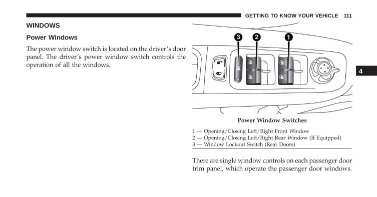
WINDOWS
Power Windows
The power window switch is located on the driver’s doorpanel. The driver’s power window switch controls theoperation of all the windows.
There are single window controls on each passenger doortrim panel, which operate the passenger door windows.
Power Window Switches
1 — Opening/Closing Left/Right Front Window2 — Opening/Closing Left/Right Rear Window (If Equipped)3 — Window Lockout Switch (Rear Doors)
4
GETTING TO KNOW YOUR VEHICLE 111

The window controls will operate only when the ignitionis in the MAR/RUN or AVV/START position.
NOTE: For vehicles equipped with Uconnect, the powerwindow switches will remain active for up to threeminutes after the ignition is cycled to the STOP/OFFposition. Opening either front door will cancel thisfeature. Refer to “Uconnect Settings” in “Multimedia” forfurther information.
WARNING!
• Never leave children unattended in a vehicle, anddo not let children play with power windows. Donot leave the key fob in or near the vehicle, or in alocation accessible to children, and do not leave theignition of a vehicle equipped with Keyless Enter-N-Go in the MAR/RUN mode. Occupants, particu-larly unattended children, can become entrapped
(Continued)
WARNING! (Continued)by the windows while operating the power win-dow switches. Such entrapment may result in seri-ous injury or death.
Controls
AUTO-Down Feature — If Equipped
The driver and passenger power window switches havean AUTO-down feature. Push the switch for half asecond and release it, the window will go down auto-matically.
To partially open the window, push the window switchand release it when you want the window to stop.
To stop the window from going all the way down duringthe AUTO-down operation, pull up on the switch brieflywhen the window has reached the desired position.
112 GETTING TO KNOW YOUR VEHICLE

AUTO-Up Feature With Auto-Reverse Protection — IfEquipped
Lift and hold the window switch for half a second,release, and the window will go up automatically.
To stop the window from going all the way up during theAUTO operation, push down on the switch briefly.
To partially close the window, lift the window switch andrelease it when you want the window to stop.
NOTE:
• If the window runs into any obstacle during auto-closure, it will reverse direction and then go backdown. Remove the obstacle and use the windowswitch again to close the window.
• Any impact due to rough road conditions may triggerthe auto-reverse function unexpectedly during auto-closure. If this happens, pull the switch lightly andhold to close the window manually.
WARNING!
There is no Auto-Reverse protection when the win-dow is almost closed. Be sure to clear all objects fromthe window before closing.
Reset Auto-Up
Should the Auto Up feature stop working, the windowprobably needs to be reset. To reset Auto Up:
1. Pull the window switch up to close the windowcompletely and continue to hold the switch up for anadditional two seconds after the window is closed.
4
GETTING TO KNOW YOUR VEHICLE 113

Wind Buffeting
Wind buffeting can be described as the perception ofpressure on the ears or a helicopter-type sound in theears. Your vehicle may exhibit wind buffeting with thewindows down, or the sunroof in certain open or par-tially open positions. This is a normal occurrence and canbe minimized. If the buffeting occurs with the rearwindows open, open the front and rear windows to-gether to minimize the buffeting. If the buffeting occurswith the sunroof open, adjust the sunroof opening tominimize the buffeting or open any window.
CLIMATE CONTROLS
Air Outlet And Diffuser Locations — PassengerCompartment
Left Side Air Outlets1 — Adjustable Air Outlet2 — Air Vane Adjustment3 — Air Flow Outlet Adjustment4 — Fixed Air Outlet
114 GETTING TO KNOW YOUR VEHICLE

Center Air Outlets
1 — Fixed Air Outlet2 — Air Flow Outlet Adjustment3 — Air Vane Adjustment4 — Adjustable Air Outlet
Right Side Air Outlets
1 — Fixed Air Outlet2 — Adjustable Air Outlet3 — Air Vane Adjustment4 — Air Flow Outlet Adjustment
4
GETTING TO KNOW YOUR VEHICLE 115

Manual Climate Controls — If Equipped
The Manual Climate Controls consist of a series of rotarydials with inner push buttons.
1. Blower Control
Rotate this control knob to regulate the amount of airforced through the ventilation system in any mode. Theblower speed increases as you move the control clock-wise from the “0” (OFF) position.
2. Temperature Control
Rotate this control knob to regulate the temperature ofthe air inside the passenger compartment. Rotating thedial counter-clockwise towards the blue area of the scaleindicates cooler temperatures, while rotating clockwisetowards the red area indicates warmer temperatures.Rotating the Temperature Control Knob all the waycounter-clockwise results in turning on the MAX A/Cfeature.
3. Mode Control
Rotate this control knob to change the system betweenModes (Panel, Bi-Level, Floor, Mix, Defrost).
Manual Temperature Controls (MTC)
116 GETTING TO KNOW YOUR VEHICLE

• PanelAir is directed through the outlets in theinstrument panel. These outlets can be ad-justed to direct airflow.
NOTE: The center instrument panel outlets can be ad-justed so that they are directed toward the rear seatpassengers for maximum airflow to the rear.
• Bi-LevelAir is directed through the panel and flooroutlets.
• FloorAir is directed through the floor outlets with asmall amount flowing through the defrost andside window demister outlets.
• MixAir is directed through the floor, defrost, andside window demister outlets. This settingworks best in cold or snowy conditions that
require extra heat to the windshield. This setting isgood for maintaining comfort while reducing mois-ture on the windshield.• Defrost
Air is directed through the windshield andside window demister outlets. Use this mode
with maximum blower and temperature settings forbest windshield and side window defrosting.
NOTE: The air conditioning compressor operates in Mixor Defrost, even if the Air Conditioning (A/C) button isnot pushed. This dehumidifies the air to help dry thewindshield. To improve fuel economy, use these modesonly when required.
4
GETTING TO KNOW YOUR VEHICLE 117

4. Rear Defrost Button
Push and release the Rear Defrost Control button to turnON the rear window defroster and the heated outsidemirrors (if equipped). An indicator will illuminate whenthe rear window defroster is ON. The rear windowdefroster automatically turns OFF after 20 minutes.
5. A/C Button — If Equipped
Push this button to engage the Air Conditioning. Anindicator will illuminate when the Air Conditioningsystem is engaged.
6. Recirculation Button
Push this control button to change the system betweenrecirculation mode and outside air mode. Recirculationcan be used when outside conditions such as smoke,odors, dust, or high humidity are present.
NOTE:
• Continuous use of the Recirculation mode may makethe inside air stuffy and window fogging may occur.Extended use of this mode is not recommended.
• The use of the Recirculation mode in cold or dampweather could cause windows to fog, because ofmoisture buildup inside the vehicle. Select the out-side air position for maximum defogging.
• Recirculation can be used in all modes except forDefrost.
• The A/C can be deselected manually without dis-turbing the mode control selection.
118 GETTING TO KNOW YOUR VEHICLE

Rear Window Defrosting
Push and release the rear window defrost button to turnthe function on/off.
Activation of this function is indicated by the rear defrostindicator light on the instrument panel turning on. Thefunction is automatically deactivated after 20 minutes.
If equipped, push the rear defrost button to activate thedefrosting of door mirrors and heated rear window.
CAUTION!
To avoid causing damage to the rear window de-froster heating filaments do not affix stickers or otherobjects to the inside of the rear glass.
Air Recirculation
Push and release the Air Recirculation button so that theLED is on, to enter recirculation mode. It is recommendedto turn the internal air recirculation on while standing intraffic or in tunnels to prevent the introduction of pol-luted air.
Do not use the function for a long period of time,particularly if there are many passengers in the vehicle,to prevent the windows from misting up.
NOTE: Internal air recirculation makes it possible toreach the required heating or cooling conditions quicklydepending on the mode selected. Do not use the internalair recirculation function on rainy/cold days as it wouldconsiderably increase the possibility of the windowsmisting.
4
GETTING TO KNOW YOUR VEHICLE 119

System Maintenance
In winter, the Climate Control system must be turned onat least once a month for approximately 10 minutes.
Have the system inspected at an authorized dealershipbefore the summer.
NOTE: The system uses R-1234yf (refrigerant) whichdoes not pollute the environment in the event of acciden-tal leakage. Under no circumstances is the use of R-134a(refrigerant) allowed.
Automatic Climate Controls — If Equipped
1. Driver Temperature Control
Provides the driver with independent temperature con-trol. Rotate the adjustment knob to set desired tempera-ture shown in the Temperature Display. Rotate counter-clockwise till LO is shown for maximum A/C (LO).
Automatic Climate Controls
120 GETTING TO KNOW YOUR VEHICLE

2. A/C Button
Push the A/C Control Button to change the currentsetting. The indicator illuminates when the A/C is ON.Pushing the “AUTO” control button will cause A/Coperation to switch into AUTO mode; the A/C indicatorwill turn OFF.
3. MAX Defrost Button
Push the MAX Defrost button to change the currentairflow setting to Defrost mode. The indicator illuminateswhen this feature is ON. Performing this function willcause the automatic climate controls to change to manualmode. The blower speed increases to full (all LEDs ON)when MAX Defrost mode is selected, the air conditioningcompressor is turned ON (LED ON), both driver andpassenger temperature controls are set to (HI), defrostmode is selected (LED ON), rear defroster is turned ON(LED ON) and the air recirculation is turned OFF (LED
OFF). If the MAX Defrost mode is turned OFF, the climatesystem will return to the previous setting.
4. Blower Control Indicator LEDs
A total of eight LEDs illuminate to visually indicateblower speeds.
5. Rear Defrost Button
Push the Rear Defrost button to turn ON the rear windowdefroster and the heated outside mirrors (if equipped).An indicator will illuminate when the rear windowdefroster is ON. The rear window defroster automaticallyturns OFF after 20 minutes.
6. AUTO Button
Push this button to automatically control the interiorcabin temperature by adjusting airflow distribution andamount. Performing this function will cause the auto-matic climate controls to change between manual modeand automatic modes.
4
GETTING TO KNOW YOUR VEHICLE 121

7. Passenger Temperature Control
Provides the passenger with independent temperaturecontrol. Rotate the adjustment knob to set desired tem-perature shown in the Temperature Display.
NOTE: Rotating the Passenger Temperature Controlknob while in Sync mode will automatically exit Sync.
8. Passenger Temperature Display
Rotate the Passenger Temperature Control dial clockwiseor counter-clockwise to adjust the air temperature in thefront right (Passenger Temperature Control) zone of thepassenger compartment. The set temperature is shownon the display. Turning the control knob completely inone direction or the other activates the �HI� (maximumheating) or �LO� (maximum cooling) functions shown inthe display, respectively. To deactivate these functions,turn the temperature knob to the desired temperature.
9. SYNC Button
Push the Sync button to toggle the Sync feature ON/OFF.The Sync indicator will illuminate when this feature isenabled. Sync is used to synchronize the passenger tempera-ture setting with the driver temperature setting. Changingthe passenger temperature setting while in Sync mode willautomatically exit this feature and return to the separatemanagement of air temperatures in the two zones.
10. Mode Buttons
Airflow distribution modes can be adjusted so air comesfrom the instrument panel outlets, floor outlets, de-mistoutlets and defrost outlets by selecting these buttons.One, two or all modes may be selected at any one time.
11. Blower Control
Blower control is used to regulate the amount of airforced through the climate system. AUTO Mode willchange to manual mode automatically when adjusting
122 GETTING TO KNOW YOUR VEHICLE

the Blower Control Knob. The speeds can be selected byrotating the Blower Control adjustment knob.
12. ON/OFF Button
Push this button to turn the Climate Control ON/OFF.
13. Recirculation Button
Push to change the current setting. The Indicator illumi-nates when ON.
NOTE:
• When in Max Defrost mode, the Recirculation buttonwill change the setting to normal Defrost mode. Thisindicates that you can not enter to this mode due tofogging risk.
• When the Auto indicator is ON and the Recirculationindicator is OFF, the Recirculation is in AUTO mode.If the Recirculation indicator is ON, the Recirculationsetting is manual and Recirculation is ON.
14. Driver Temperature Display
Rotate the Driver Temperature Control knob clockwise orcounter-clockwise, to adjust the air temperature in thefront left (Driver Temperature Control) zone of the pas-senger compartment. The set temperature is shown onthe display. Turning the control knob completely in onedirection or the other activates the �HI� (maximum heat-ing) or �LO� (maximum cooling) functions shown in thedisplay, respectively. To deactivate these functions, turnthe temperature knob to the desired temperature.
Description
The Automatic Dual Zone Climate Control system regu-lates the air temperatures in the passenger compartmentin two zones: driver side and passenger side.
The system maintains comfort inside the passenger com-partment and compensates for possible variations inexternal climate conditions.
4
GETTING TO KNOW YOUR VEHICLE 123

The Climate Control system can recognize extremely cold(or extremely hot) conditions in the passenger compart-ment and provide optimal management of the system’scapabilities.
NOTE: The reference temperature is 72° F (22° C) foroptimal comfort management.
The automatically controlled functions are:
• Air temperature at the driver/front passenger sidevents.
• Blower speed (continuous variation of the air flow).
• Compressor engagement (for cooling/dehumidifyingthe air).
• Air recirculation.
All these functions can be adjusted manually by operat-ing the system, selecting one or more functions andmodifying their parameters.
Automatic control of the functions will be suspended: thesystem will only override the settings for safety reasons.
Manual selections always take priority over automaticones and are stored until the AUTO button is pushed orthe system itself intervenes for specific safety reasons.
The amount of air introduced into the passenger com-partment is not affected by car speed; it is regulated bythe fan, which is controlled electronically.
The air temperature is always automatically controlledaccording to the temperature set on the display (exceptfor when the system is off or in certain conditions whenthe compressor is not running).
The system allows the following to be set or adjustedmanually:
• Driver/passenger side air temperature
• Blower speed (continuous variation)
124 GETTING TO KNOW YOUR VEHICLE

• Air distribution to seven positions
• Compressor activation
• Rapid defrosting/demisting function
• Air recirculation
• Heated rear window
• System deactivation
NOTE: The Climate Control system detects the passengercompartment temperature using a temperature sensor,located in the lower instrument panel between the centerconsole and the steering wheel.
Turning On The Climate Control System
The Climate Control system can be turned on in differentways. It is recommended to turn the Temperature Controlknobs to set the desired temperatures and then push theAUTO button.
The system operates automatically to adjust the tempera-ture, quantity and distribution of the air introduced intothe passenger compartment. It also manages the airrecirculation function and the activation of the air condi-tioning compressor.
During automatic operation, you can change the settemperatures, air distribution and blower speed at anytime by using the relevant buttons or knobs: the systemwill automatically change the settings to adjust to thenew requirements.
During automatic operation (AUTO), varying the airflow and/or distribution or pushing the A/C controlbutton causes the AUTO function LED to turn off and thesystem to operate in MANUAL mode.
4
GETTING TO KNOW YOUR VEHICLE 125

Adjusting The Air Temperature
Rotate the Driver Temperature Control, or the PassengerTemperature Control, dial clockwise or counter-clockwise, to adjust the air temperature in the front left(Driver Temperature Control) or right (Passenger Tem-perature Control) zone of the passenger compartment.
The set temperatures are shown on the displays.
Push the SYNC button to align the air temperaturebetween the two zones.
Turn the Passenger Temperature Control knob to returnto the separate management of air temperatures in thetwo zones.
Turning the control knobs completely in one direction orthe other activates the �HI� (maximum heating) or �LO�(maximum cooling) functions respectively.
To deactivate these functions, turn the temperature knobto the desired temperature.
Air Distribution Selection
By pushing the Mode Control buttons (Defrost/Panel/Floor buttons), it is possible to set one of the sevenpossible air distributions manually by activating one ormore mode buttons:
• Defrost Mode – Air flow to the windshield and frontside window diffusers to defrost them. Use Defrostmode with maximum temperature settings for bestwindshield and side window defrosting.
• Panel Mode – Air flow is distributed between thecentral and side instrument panel vents.
• Floor Mode – Air flow is directed from the front andrear footwell diffusers.
126 GETTING TO KNOW YOUR VEHICLE

• Floor and Panel Modes – Air flow is distributedbetween the footwell diffusers and the central and sideinstrument panel vents.
• Floor and Defrost Modes – Air flow distributed be-tween footwell diffusers and windshield and front sidewindow defrosting diffusers. This distribution settingallows the passenger compartment to be warmedeffectively and prevents the windows from misting.
• Defrost and Panel Modes – Air flow distributionbetween windshield defrosting diffusers and side andcentral instrument panel vents.
• Defrost, Panel and Floor Modes – Air flow distributionto all the diffusers.
NOTE: Air always flows from the side instrument paneldiffusers: it is, however, possible to interrupt the air flowby operating the wheel located near the correspondingvents.
In AUTO mode, the climate control system automaticallymanages air distribution (LEDs on the Mode Controlbuttons are off).
When set manually, the air distribution is indicated bythe LEDs on the selected buttons turning on.
In combined function mode, functions are enabled to-gether with those already set when the relevant button ispushed. If a button whose function is already active ispushed, the operation is cancelled and the correspondingLED turns off.
To restore automatic control of the air distribution after amanual selection, push the AUTO button.
Adjusting The Fan Speed
Rotate the Blower Control knob to increase/decrease thefan speed.
4
GETTING TO KNOW YOUR VEHICLE 127

The speed is indicated by the eight Blower ControlIndicator LEDs, located above the Blower Control knob,turning on.
• Maximum blower speed = all Indicators illuminated
• Minimum blower speed = one Indicators illuminated
The blower can only be turned off if the A/C compressorhas been turned off by pushing the A/C Control button.
NOTE: To restore automatic control of the fan speed aftera manual adjustment, push the AUTO button.
AUTO Button
When the AUTO button is pushed (Indicator illumi-nated), the Climate Control system automatically adjuststhe following settings in the corresponding zones:
• Quantity and distribution of the air introduced into thepassenger compartment.
• Climate Control system compressor.
• Air Recirculation.
Cancelling all previous manual adjustments.
This is indicated by the AUTO button Indicator turningon.
If the AUTO button is pushed when the AUTO Indicatoris on, the system changes to manual mode; it displays thecurrent flow and distribution status, which will no longerbe managed automatically.
If a manual adjustment is made to the air distribution, theA/C button or the blower speed, the Indicator turns offto indicate that the system is no longer controlling allfunctions automatically.
To restore automatic system control after one or moremanual adjustments, push the AUTO button.
128 GETTING TO KNOW YOUR VEHICLE

SYNC Button
Push the “SYNC” button (Indicator illuminated) to cor-relate the passenger side air temperature with that of thedriver side.
This function makes temperature regulation easier whenthe driver is travelling alone.
Turn the Passenger Temperature Control knob to set thepassenger side temperature and return to separate airtemperature management.
Air Recirculation
The Air Recirculation is managed by the following:
• Forced activation (air recirculation always on): indi-cated by the Indicator on the Recirculation Controlbutton.
• Forced deactivation (air recirculation always off, airintake from the outside), signalled by the Indicator onthe Recirculation Control button switching off.
Forced activation/deactivation can be selected by push-ing the Recirculation Control button.
When the On/Off button is pushed, the Climate Controlsystem automatically activates internal air recirculation(Indicator on Recirculation Control button on).
In automatic operation, recirculation is managed auto-matically by the system according to outside environ-mental conditions.
4
GETTING TO KNOW YOUR VEHICLE 129

NOTE:
• Use of the recirculation system makes it possible toreach the required heating/cooling conditions faster. Itis not recommended to use it on rainy/cold days as itwould considerably increase the possibility of thewindows misting up inside (especially if the ClimateControl system is off). When the outside temperatureis low, recirculation is forced off (air drawn in from theoutside) to prevent the windows from misting up.
• It is not recommended to use internal air recirculationwhen the outside temperature is low, since the win-dows could mist up rapidly.
• When defrost mode is selected recirculation is turnedoff to prevent the windows from misting up.
Climate Control System Compressor
Push the A/C Control button to activate/deactivate thecompressor (activation is indicated by the Indicator onthe button turning on).
The status of the compressor will be remembered for thenext engine run after the engine had stopped.
Push the A/C button to stop AUTO MODE (AUTOIndicator will turn off). To restore automatic control ofcompressor, push the AUTO button again.
NOTE: With the compressor off, air cannot be introducedto the passenger compartment with a temperature lowerthan the outside temperature. Under certain environmen-tal conditions, windows could mist rapidly since the airis not dehumidified.
MAX A/C
MAX A/C sets the system for maximum cooling perfor-mance.
Rotate the driver temperature control adjust knobcounter-clockwise for MAX A/C. Both driver and pas-senger temperature displays will show MAX A/C LO.
130 GETTING TO KNOW YOUR VEHICLE

In MAX A/C, the blower speed and mode position can beadjusted to desired user settings. Pressing other settingswill cause the MAX A/C operation to switch to theselected setting and MAX A/C to exit.
Rapid Window Demisting (MAX-Defrost function)
Push the MAX-defrost button to activate (LED on) thewindshield and side window demisting function.
The Climate Control system carries out the followingoperations:
• Turns on the air conditioning compressor when envi-ronmental conditions are suitable.
• Turns air recirculation off.
• Sets blower fan to the maximum speed.
• Directs air flow to windshield and front side windowdiffusers.
• Activates the heated rear window defrost.
• Activates the heated windshield (if equipped).
• Displays the fan speed (Blower Control Indicator LEDilluminated).
When the function is activated, the AUTO button LED turnsoff. With the function activated, the only possible manualadjustments are pushing the A/C control button, adjustingthe fan speed and turning the heated rear window off.
When the Recirculation Control or AUTO buttons arepushed, the Climate Control system will deactivate theFront Defrost (MAX-DEF) function.
Selecting the footwell/windshield or only windshield dis-tribution activates the Climate Control system compressorand the air recirculation is set to �outside air� intake.
This logic guarantees optimum visibility at the windows.Max-defrost is also available in manual mode.
4
GETTING TO KNOW YOUR VEHICLE 131

Rear Window Defrosting
Push and release the rear window defrost button to turnthe function on/off.
Activation of this function is indicated by the rear defrostindicator light on the instrument panel turning on. Thefunction is automatically deactivated after 20 minutes.
If equipped, push the rear defrost button to activate thedefrosting of door mirrors and heated rear window.
CAUTION!
To avoid causing damage to the rear window de-froster heating filaments do not affix stickers or otherobjects to the inside of the rear glass.
Turning Off The Climate Control System
Push the ON/OFF button.
With the Climate Control system off:
• Air recirculation is on, isolating the passenger com-partment from the outside.
• The A/C compressor is off.
• The blower is off.
• The heated rear window can be activated/deactivated.
132 GETTING TO KNOW YOUR VEHICLE

NOTE: The Climate Control Unit stores the temperaturesset before the system was turned off and restores themwhen one of the following knobs/buttons is pushed:
• A/C
• Recirculation
• Max Defrost
• Blower Increase
• AUTO
To achieve fully automatic mode, push the AUTO button.
System Maintenance
In winter, the Climate Control system must be turned onat least once a month for approximately 10 minutes.
Have the system inspected at an authorized dealershipbefore the summer.
NOTE: The system uses R-1234yf (refrigerant) whichdoes not pollute the environment in the event of acciden-tal leakage. Under no circumstances is the use of R-134a(refrigerant) allowed.
4
GETTING TO KNOW YOUR VEHICLE 133

MY SKY SUN ROOF — IF EQUIPPED
Removable Roof — If Equipped
The roof consists of front and rear panels that can beremoved independently.
On some vehicles the front panel can be power operatedrefer to “Power My Sky” in this section.
My Sky Retractable Roof
My Sky Retractable Roof Removed
134 GETTING TO KNOW YOUR VEHICLE

CAUTION!
The panels are able to withstand the snow. However,it is recommended that you remove excessive layersof snow that have accumulated or damage to thepanels may occur.
Power My Sky — If Equipped
Open/Close The Front Panel
The power My Sky switches are located on the overheadconsole. The switches are used to open and close the frontpanel. Front Panel Operation Switch
4
GETTING TO KNOW YOUR VEHICLE 135

To retract the front panel to the open position, push theOpen/Close button.
From the fully open position, pull the Open/Closeswitch: the front panel will close completely.
Venting The Front Panel
To vent the front panel push and release the vent switch.
During the vent operation any push on the Open/Closeswitch will stop the closing of the panel.
NOTE: If the My Sky is in open position, the vent switchmust be held until the panel vents.
Anti-Pinch Feature
The front panel of the retractable roof is equipped with aanti-pinch safety system that is able to detect the pres-ence of an obstacle during the opening and closingmotion of the panel.
When this event occurs, the front panel stops and re-verses immediately.
Operation Switch
1 — Front Panel Open/Close Switch2 — Front Panel Vent Switch
136 GETTING TO KNOW YOUR VEHICLE

NOTE: With both panels removed the retractable roofcannot be opened or closed.
Removing And Installing Panels
NOTE:
• Remove the panels only when the vehicle is stationary.
• The rear panel can be removed only when the frontpanel is completely closed or removed.
Removing Panels
1. Front panel must be in the closed position to removepanels.
2. Locate the My Sky Key inside the panel storage bag inthe cargo area.
My Sky Key
4
GETTING TO KNOW YOUR VEHICLE 137

3. From inside of the passenger compartment, insert theMy Sky Key into the latch key hole.
4. Rotate and keep the key turned to the symbol torelease the lock.
Latch Key Hole Rotating My Sky Key
138 GETTING TO KNOW YOUR VEHICLE

5. Pull the panel handle down and away from thestowed position, unlocking the panel.
6. Remove the key from the Latch Key Hole.
Unlocking Panel HandleRemoving Key
4
GETTING TO KNOW YOUR VEHICLE 139

7. Push panel up and away from latch to create a smallgap.
8. Remove the panel from the outside of the vehicle.
9. Place the panel inside of the provided bag for storagein the cargo area. Repeat the process for the RearPanel.
NOTE: An air deflector is available on the Jeep accessoryline. This deflector may be used to avoid the “tunneleffect” inside the vehicle, if the front panel is removed.
Push Panel Up
Removing Panel
140 GETTING TO KNOW YOUR VEHICLE
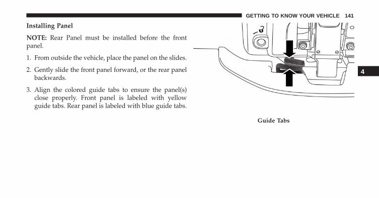
Installing Panel
NOTE: Rear Panel must be installed before the frontpanel.
1. From outside the vehicle, place the panel on the slides.
2. Gently slide the front panel forward, or the rear panelbackwards.
3. Align the colored guide tabs to ensure the panel(s)close properly. Front panel is labeled with yellowguide tabs. Rear panel is labeled with blue guide tabs.
Guide Tabs
4
GETTING TO KNOW YOUR VEHICLE 141

4. From inside the vehicle, pull the handle down andtoward the stowed position, locking it into place.
5. Make sure that the panel has been properly refitted.From inside the passenger compartment, push up-ward on the panel from the bottom, in order to verifythat it is properly latched to the clamping locks.
Closing Panel Handle
Push To Lock Panel
142 GETTING TO KNOW YOUR VEHICLE

Bag For Housing Panels — If Equipped
After the panels have been removed, store the roof panelsinside of the bag located inside the storage compartment.
NOTE: It is recommended to do this procedure outside ofthe vehicle.
Roof Panel Bag
4
GETTING TO KNOW YOUR VEHICLE 143

For proper housing, proceed as follows:
1. Open the Roof Panel Bag and lift the panel dividerstoward the outside.
2. Place the first panel into the bag and fold the paneldividers down.
Panel Dividers
First Panel In Storage Bag
144 GETTING TO KNOW YOUR VEHICLE

3. Place the second panel into the bag on top of dividers.
4. Close the bag and place it on the inside the cargo area.
5. Open the Velcro straps provided on the bag. Anchorthem firmly at the tie-down hooks located in the cargoarea.
Second Panel In Storage Bag
Tie-Down Hook Locations
4
GETTING TO KNOW YOUR VEHICLE 145

NOTE:
• Do not load objects that weigh over 165 pounds (75 kg)on top of the roof panel bag.
• The bag is washable. Refer to the documentation thatis supplied with the bag.
Emergency Open/Close
If the Power My Sky switch fails, the retractable roof canbe operated manually as follows:
1. Remove the protective cap located on the inner lining.
2. Remove the Allen Key or My Sky Key that is suppliedin the tool bag in the cargo area.
3. Insert the Allen Key or My Sky Key into the key holeand turn it clockwise to open the roof or counter-clockwise to close.
Tie-Down Straps
146 GETTING TO KNOW YOUR VEHICLE

CAUTION!
• When refitting panels, be careful to avoid fingers,scarves, ties and items of clothing from gettingcaught under the panels themselves.
• Do not open the roof in the presence of snow or ice.There is risk of damage.
Emergency Key And Key Hole
1 — Key Hole2 — Allen Key
4
GETTING TO KNOW YOUR VEHICLE 147

HOOD
Opening
Two latches must be released to open the hood.
Pull the hood release lever located under the drivers sideof the instrument panel.
Move to the outside of the vehicle and push the safetylatch release lever toward the passenger side of thevehicle. The hood release lever is located behind thecenter front edge of the hood.
Hood Release Lever
Safety Latch
1 — Safety Latch Location
148 GETTING TO KNOW YOUR VEHICLE

Remove the support rod from the locking tab and insertit into the seat located on the underside of the hood. Besure the rod is locked into position.
Locking Tab
Support Rod And Seat
1 — Support Rod2 — Support Rod Seat
4
GETTING TO KNOW YOUR VEHICLE 149

Closing
Hold up the hood with one hand and with the other handremove the support rod from its seat and reinsert it intothe locking tab.
Lower the hood to approximately 6 inches (15 cm) fromthe engine compartment and drop it. Make sure that thehood is completely closed.
WARNING!
Be sure the hood is fully latched before driving yourvehicle. If the hood is not fully latched, it could openwhen the vehicle is in motion and block your vision.Failure to follow this warning could result in seriousinjury or death.
CAUTION!
To prevent possible damage, do not slam the hood toclose it. Lower hood to approximately 12 in (30 cm)and drop the hood to close. Make sure hood is fullyclosed for both latches. Never drive vehicle unlesshood is fully closed, with both latches engaged.
LIFTGATE
Opening
To unlock the liftgate, use the key fob or activate thepower door lock switches located on the driver doorhandle.
To open the liftgate, squeeze the electronic liftgate releaseand pull the liftgate open with one fluid motion.
150 GETTING TO KNOW YOUR VEHICLE

The Liftgate Passive Entry unlock feature is built into theElectronic Liftgate release. With a valid Passive Entry keyfob within 3 ft (1.0 m) of the Liftgate, push the ElectronicLiftgate release to open with one fluid motion.
To open the liftgate, squeeze the electronic liftgate releaseand pull the liftgate open with one fluid motion.
Liftgate Handle Location
1 — Liftgate Handle
Passive Entry Liftgate Handle Location
1 — Electronic Liftgate Release/Liftgate Passive Entry Location
4
GETTING TO KNOW YOUR VEHICLE 151

Emergency Opening
Proceed as follows:
1. Remove the rear shelf (if equipped).
2. Fold the rear seats forward.
3. Using the supplied screwdriver (located under cargofloor in tool kit), remove the yellow tab.
Emergency Opening Tab Location
1 — Yellow Tab
152 GETTING TO KNOW YOUR VEHICLE

4. Insert the screwdriver into the release tab slot totrigger the release tab of the Liftgate.
Closing
Grasp the liftgate closing handle and initiate lowering theliftgate. Release the handle when the liftgate takes overthe closing effort.
Emergency Release Tab Slot Location
1 — Release Tab Slot
1 — Liftgate Closing Handle
4
GETTING TO KNOW YOUR VEHICLE 153

NOTE: Before closing the Liftgate, make sure to be inpossession of the key because the Liftgate will be lockedautomatically.
Cargo Area Features
Cargo Load Floor
The vehicle is equipped with a load floor that can beadjusted as needed.
Position 1 (Lowered Position):
This position allows you to make the load floor flat forease of loading/unloading objects from the cargo area.This position also makes it possible to use the spacebelow as another compartment for storing fragile orsmaller objects.
Position 2 (Elevated Position):
When the rear seatbacks and front passenger seat isfolded flat, it will allow for loading objects of longdimensions. It is recommended to use this position onlyduring the actual transporting of the objects, then bringthe load floor in position 1.
Table Tilt Load
In addition to the two positions described above, the loadfloor can also be placed in a tilted position (slantedtoward the rear seatbacks as to ease the access to theunderlying zone of the luggage compartment (e.g. to pickup the spare tire or the Tire Service Kit).
Place the load floor in a way that it rests at the supports1 and 2 on the sides of the cargo area.
154 GETTING TO KNOW YOUR VEHICLE

The load floor provides securing of any cargo inside thisposition, so that the cargo will slide in the case of suddenbraking.
Load Floor
Table Tilt Load Supports
1 — Loading Floor Support One2 — Loading Floor Support Two
4
GETTING TO KNOW YOUR VEHICLE 155

Access To The Loading Floor
To access the double load compartment, proceed asfollows:
1. Lift up on the Load Floor Handle.
2. Place the desired objects inside the compartment.
3. Reposition the load floor.
Load Floor Handle
1 — Cargo Load Floor2 — Cargo Load Floor Handle
156 GETTING TO KNOW YOUR VEHICLE

CAUTION!
The load floor must be arranged in a central positionwith respect to cargo area.
Displacement Load Floor
To position the load from the lower to the upper position,proceed as follows:
1. Grasp the load floor handle and lift up the load floor.
2. Correctly place the load floor on the side panel guidesand on the rear cross member.
Access To Tire Service Kit Or Spare Tire
To access the Tire Service Kit or spare tire and containercarrier, proceed as follows:
1. Grasp the load floor handle and remove the floor.
2. Pull the tab and lift up on the carpet.
Cargo Area Storage
4
GETTING TO KNOW YOUR VEHICLE 157

Anchoring Of The Load
The cargo tie-downs, located on the cargo area floor,should be used to safely secure loads when the vehicle ismoving.
The side panels maybe equipped with three groceryhooks (one on the left side and two on the right side) forsecuring loads that are not excessively heavy.
Tie-Downs
Grocery Hook
158 GETTING TO KNOW YOUR VEHICLE

Rear Power Outlet
The rear cargo power outlet is located on the left side ofthe cargo area.
The outlet only works when the ignition is in theMAR/RUN position.
Grocery Hooks
Rear 12 Volt Cargo Power Outlet
4
GETTING TO KNOW YOUR VEHICLE 159

NOTE: The rear cargo power outlet can be changed to“battery” powered all the time by switching the poweroutlet Integrated Power Module 20A fuse from fuselocation F18 to F30. Refer to “Engine CompartmentFuses” in “In Case Of Emergency” for further informa-tion.
CAUTION!
Do not connect devices with power higher than 180Watts (15 Amps) to the socket. Do not damage thesocket by using unsuitable adaptors. If the 180 Watt(15 Amp) power rating is exceeded the fuse protect-ing the system will need to be replaced.
WARNING!
To avoid serious injury or death:• Only devices designed for use in this type of outlet
should be inserted into any 12 Volt outlet.• Do not touch with wet hands.• Close the lid when not in use and while driving the
vehicle.• If this outlet is mishandled, it may cause an electric
shock and failure.
160 GETTING TO KNOW YOUR VEHICLE

Cargo Box — If Equipped
The cargo area contains a preformed cargo box that canbe used for the storage of objects that allows you toobtain a uniform level when loading.
NOTE: The cargo box is sized for a maximum capacity ofdistributed weight equal to 242 lbs (110 kg).
INTERNAL EQUIPMENT
Glove Compartment
The glove compartment is located on the passengers sideof the instrument panel.
To open the glove compartment proceed as follows:
1. Unlock the compartment using the vehicle key.
Cargo Box
4
GETTING TO KNOW YOUR VEHICLE 161

2. Pull the handle to open the compartment. Once the glove compartment is open, a light will turn onto illuminate the compartment.
NOTE:
• Do not insert objects in the glove compartment thatwill not allow the compartment to fully close.
• The glove compartment should be completely closedwhile the vehicle is in motion.
Opening The Glove Compartment
1 — Glove Compartment Handle
162 GETTING TO KNOW YOUR VEHICLE

Sun Visors
Sun visors are located on both sides of the rearviewmirror. The visors can be lowered or moved to the side tohelp block sunlight from entering the windshield or doorglass.
To move the sun visor against the driver or passengerdoor glass, remove the sun visor from the hook and turnit toward the side window.
The visors also have illuminated vanity mirrors to allowuse in low light conditions.
Lift upward on the mirror cover to access the mirror.
Sun Visor Mirror
1 — Sun Visor Mirror Cover
4
GETTING TO KNOW YOUR VEHICLE 163

Extendible Sun Visor
To extend the sun visor, proceed as follows:
1. Place the sun visor against the door glass by detachingit from the hook and turning it toward the sidewindow.
2. Slide the visor along the rod to provide coverage moreto the rear.
Sliding Sun Visor
1 — Sun Visor
164 GETTING TO KNOW YOUR VEHICLE
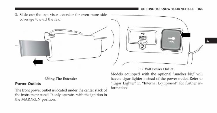
3. Slide out the sun visor extender for even more sidecoverage toward the rear.
Power Outlets
The front power outlet is located under the center stack ofthe instrument panel. It only operates with the ignition inthe MAR/RUN position.
Models equipped with the optional �smoker kit,� willhave a cigar lighter instead of the power outlet. Refer to“Cigar Lighter� in “Internal Equipment” for further in-formation.
Using The Extender
12 Volt Power Outlet
4
GETTING TO KNOW YOUR VEHICLE 165

CAUTION!
Do not connect devices with power higher than 180Watts (15 Amps) to the socket. Do not damage thesocket by using unsuitable adaptors. If the 180 Watt(15 Amp) power rating is exceeded the fuse protect-ing the system will need to be replaced.
WARNING!
To avoid serious injury or death:• Only devices designed for use in this type of outlet
should be inserted into any 12 Volt outlet.• Do not touch with wet hands.• Close the lid when not in use and while driving the
vehicle.• If this outlet is mishandled, it may cause an electric
shock and failure.
CAUTION!
• Many accessories that can be plugged in drawpower from the vehicle’s battery, even when not inuse (i.e., cellular phones, etc.). Eventually, ifplugged in long enough, the vehicle’s battery willdischarge sufficiently to degrade battery life and/orprevent the engine from starting.
• Accessories that draw higher power (i.e., coolers,vacuum cleaners, lights, etc.) will degrade the bat-tery even more quickly. Only use these intermit-tently and with greater caution.
• After the use of high power draw accessories, orlong periods of the vehicle not being started (withaccessories still plugged in), the vehicle must bedriven a sufficient length of time to allow thegenerator to recharge the vehicle’s battery.
166 GETTING TO KNOW YOUR VEHICLE
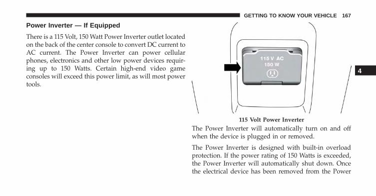
Power Inverter — If Equipped
There is a 115 Volt, 150 Watt Power Inverter outlet locatedon the back of the center console to convert DC current toAC current. The Power Inverter can power cellularphones, electronics and other low power devices requir-ing up to 150 Watts. Certain high-end video gameconsoles will exceed this power limit, as will most powertools.
The Power Inverter will automatically turn on and offwhen the device is plugged in or removed.
The Power Inverter is designed with built-in overloadprotection. If the power rating of 150 Watts is exceeded,the Power Inverter will automatically shut down. Oncethe electrical device has been removed from the Power
115 Volt Power Inverter
4
GETTING TO KNOW YOUR VEHICLE 167

Inverter it will automatically reset. To avoid overloadingthe circuit, check the power ratings on electrical devicesprior to using the Power Inverter.
WARNING!
To avoid serious injury or death:• Do not insert any objects into the receptacles.• Do not touch with wet hands.• Close the lid when not in use.• If this outlet is mishandled, it may cause an electric
shock and failure.
Cigar Lighter — If Equipped
NOTE: Cigar lighters can be purchased at an authorizeddealer through MOPAR parts. To ensure proper cigarlighter operation, a MOPAR knob and element must beused.
The cigar lighter is located on the center console. Pushlighter inward to heat.
After a few seconds, the lighter automatically returns toits initial position and is ready to be used.
Cigar Lighter
168 GETTING TO KNOW YOUR VEHICLE
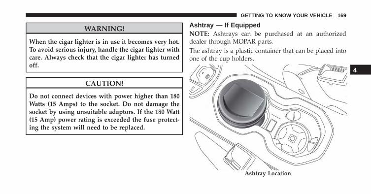
WARNING!
When the cigar lighter is in use it becomes very hot.To avoid serious injury, handle the cigar lighter withcare. Always check that the cigar lighter has turnedoff.
CAUTION!
Do not connect devices with power higher than 180Watts (15 Amps) to the socket. Do not damage thesocket by using unsuitable adaptors. If the 180 Watt(15 Amp) power rating is exceeded the fuse protect-ing the system will need to be replaced.
Ashtray — If EquippedNOTE: Ashtrays can be purchased at an authorizeddealer through MOPAR parts.The ashtray is a plastic container that can be placed intoone of the cup holders.
Ashtray Location
4
GETTING TO KNOW YOUR VEHICLE 169

Front Armrest
The front armrest is located between the front seats.
The armrest can be adjusted by moving it in the directionindicated by the arrows.
Push the storage handle and lift up the armrest to accessthe storage compartment.Front Armrest Handle
Storage Compartment
170 GETTING TO KNOW YOUR VEHICLE

WARNING!
Do not operate this vehicle with a console compart-ment lid in the open position. Driving with theconsole compartment lid open may result in injury ina collision.
Cupholders
There are two cupholders for the front seat passengers,located in the center console.
Front Cupholders
4
GETTING TO KNOW YOUR VEHICLE 171

There are two cupholders located in the rear armrest ifequipped.
Handle Grip
The handle grip is located on the passenger side of theinstrument panel. The handle can be used to enter or exitthe vehicle or when traveling on rough terrain.
Rear Cupholders
Handle Grip
172 GETTING TO KNOW YOUR VEHICLE

ROOF LUGGAGE RACK — IF EQUIPPED
Your vehicle may be equipped with a Roof Luggage Rackfor transporting accessories.
Crossbars should always be used whenever cargo isplaced on the Roof Luggage Rack. Check the strapsfrequently to be sure that the load remains securelyattached.
NOTE: Crossbars can be purchased at a authorizeddealer through Mopar parts. External racks do not in-crease the total load carrying capacity of the vehicle. Besure that the total occupant and luggage load inside thevehicle, plus the load on the Roof Luggage Rack, do notexceed the maximum vehicle load capacity.
The load carried on the roof, when equipped with aluggage rack, must not exceed 150 lbs (68 kg), and itshould be uniformly distributed over the cargo area.
Do not use the retractable roof when using the crossbars.
WARNING!
Roof rack cargo must be securely tied down beforedriving your vehicle. Improperly secured loads mayfall off the vehicle, particularly at high speeds, re-sulting in personal injury or property damage. Fol-low the Roof Luggage Rack warnings and cautionswhen carrying cargo on your roof rack.
CAUTION!
• To avoid damage to the Roof Luggage Rack andvehicle, do not exceed the maximum roof rack loadcapacity. Always distribute heavy loads as evenlyas possible and secure the load appropriately.
(Continued)
4
GETTING TO KNOW YOUR VEHICLE 173

CAUTION! (Continued)• Long loads, which extend over the windshield,
such as wood panels or surfboards, should besecured to both the front and rear of the vehicle.
• Place a blanket or other protection between thesurface of the roof and the load.
• Travel at reduced speeds and turn corners carefullywhen carrying large or heavy loads on the roofrack. Wind forces, due to natural causes or nearbytruck traffic, can add sudden upward loads. This isespecially true on large flat loads and may result indamage to the cargo or your vehicle.
174 GETTING TO KNOW YOUR VEHICLE

GETTING TO KNOW YOUR INSTRUMENT CLUSTER
CONTENTS� INSTRUMENT CLUSTER . . . . . . . . . . . . . . . . .177
▫ Instrument Cluster With Multi-FunctionalDisplay (EVIC) . . . . . . . . . . . . . . . . . . . . . . .177
▫ Instrument Cluster With ReconfigurableMulti-Functional Display (DID). . . . . . . . . . . .178
▫ Speedometer (EVIC). . . . . . . . . . . . . . . . . . . .179
▫ Speedometer (DID) . . . . . . . . . . . . . . . . . . . .180
▫ Odometer . . . . . . . . . . . . . . . . . . . . . . . . . . .181
▫ Tachometer . . . . . . . . . . . . . . . . . . . . . . . . . .181
▫ Fuel Gauge . . . . . . . . . . . . . . . . . . . . . . . . . .181
▫ Engine Coolant Temperature Gauge. . . . . . . . .182
� WARNING AND INDICATOR LIGHTS . . . . . . .183
▫ Red Telltale Indicator Lights . . . . . . . . . . . . . .184
▫ Yellow Telltale Indicator Lights . . . . . . . . . . . .194
▫ Green Telltale Indicator Lights . . . . . . . . . . . .204
▫ Blue Telltale Indicator Lights. . . . . . . . . . . . . .206
▫ White Telltale Indicator Lights . . . . . . . . . . . .207
▫ Gray Telltale Indicator Light . . . . . . . . . . . . .207
5

� ONBOARD DIAGNOSTIC SYSTEM (OBD II) . . .208
▫ Onboard Diagnostic System (OBD II)Cybersecurity . . . . . . . . . . . . . . . . . . . . . . . .208
� ELECTRONIC VEHICLE INFORMATIONCENTER (EVIC) / DRIVER INFORMATIONDISPLAY (DID) . . . . . . . . . . . . . . . . . . . . . . . .209
▫ EVIC/DID Description. . . . . . . . . . . . . . . . . .209
▫ Mapping And Reconfigurable Zone Display(EVIC) — If Equipped . . . . . . . . . . . . . . . . . .210
▫ Mapping And Reconfigurable Zone Display(DID) — If Equipped . . . . . . . . . . . . . . . . . . .212
▫ EVIC/DID Control Buttons. . . . . . . . . . . . . . .214
▫ EVIC/DID Main Menu . . . . . . . . . . . . . . . . .215
� TRIP COMPUTER . . . . . . . . . . . . . . . . . . . . . .223
▫ Quantities Displayed . . . . . . . . . . . . . . . . . . .223
▫ OK Button . . . . . . . . . . . . . . . . . . . . . . . . . .224
176 GETTING TO KNOW YOUR INSTRUMENT CLUSTER

INSTRUMENT CLUSTER
Instrument Cluster With Multi-Functional Display (EVIC)
Electronic Vehicle Information Center (EVIC) Cluster
1 — Tachometer2 — Digital Indicator Engine Coolant Temperature Warning LightWith Maximum Temperature3 — Multi-functional Display
4 — Digital Indicator Fuel Level Indicator With The Reserve (thetriangle symbol pointing toward the right indicates where thefuel filler door is located)5 — Speedometer (speed indicator)
5
GETTING TO KNOW YOUR INSTRUMENT CLUSTER 177

Instrument Cluster With Reconfigurable Multi-Functional Display (DID)
Driver Information Display (DID) Cluster
1 — Tachometer2 — Digital Indicator Engine Coolant Temperature3 — Multi-functional Display
4 — Digital Indicator Fuel Level (the triangle symbol pointingtoward the right indicates where the fuel filler door is located)5 — Speedometer (speed indicator)
178 GETTING TO KNOW YOUR INSTRUMENT CLUSTER

Speedometer (EVIC)
Indicates the speed of the vehicle in MPH or km/h.
Adjusting Instrument Panel Illumination (Light Sen-sor)
Inside the speedometer, a light sensor detects ambientlight conditions and adjusts the brightness of the instru-ment cluster.
Instrument Panel Light Sensor Zone
1 — Instrument Panel Light Sensor Zone
5
GETTING TO KNOW YOUR INSTRUMENT CLUSTER 179

The instrument works as follows:
• In �day� mode the display, the graphics, and all indexesfor the instrument cluster are fully illuminated and arenot adjustable
• In �night� mode the display, the graphics, and theindexes are adjusted accordingly. Even the light inten-sity of the automatic dual zone climate control systemand the Uconnect system display
Speedometer (DID)
Indicates the speed of the vehicle in MPH or km/h.
Adjusting Instrument Panel Illumination (Light Sen-sor)
Inside the speedometer, a light sensor detects ambientlight conditions and adjusts the brightness of the instru-ment cluster.
The instrument works as follows:
• In �day� mode the display, the graphics, and all indexesfor the instrument cluster are fully illuminated and arenot adjustable
Instrument Panel Light Sensor Zone
1 — Instrument Panel Light Sensor Zone
180 GETTING TO KNOW YOUR INSTRUMENT CLUSTER

• In �night� mode the display, the graphics, and theindexes are adjusted accordingly. Even the light inten-sity of the automatic dual zone climate control systemand the Uconnect system display
Odometer
The odometer display shows the total distance the ve-hicle has been driven.
U.S. Federal regulations require that upon transfer ofvehicle ownership, the seller certify to the purchaser thecorrect mileage that the vehicle has been driven. If yourodometer needs to be repaired or serviced, the repairtechnician should leave the odometer reading the sameas it was before the repair or service. If s/he cannot do so,then the odometer must be set at zero, and a sticker mustbe placed in the door jamb stating what the mileage wasbefore the repair or service.
It is a good idea for you to make a record of the odometerreading before the repair/service, so that you can be surethat it is properly reset, or that the door jamb sticker isaccurate if the odometer must be reset at zero.
Tachometer
Reports the number of Revolutions Per Minute (RPM) ofthe engine.
Fuel Gauge
The digital indicator on the display indicates the amountof fuel in the fuel tank.
When the fuel tank level drops to 1.3-1.85 gallons (5-7liters) remaining, a light will illuminate, a message willdisplay, and a chime will sound.
5
GETTING TO KNOW YOUR INSTRUMENT CLUSTER 181

Engine Coolant Temperature Gauge
The temperature gauge shows engine coolant tempera-ture. Any reading within the normal range indicates thatthe engine cooling system is operating satisfactorily.
The gauge pointer will likely indicate a higher tempera-ture when driving in hot weather, up mountain grades,or when towing a trailer. It should not be allowed toexceed the upper limits of the normal operating range.
In the normal use of the car, the digital scale may move indifferent positions.
Instrument Cluster With EVIC/DID
The indicator light will illuminate, a message will dis-play, and a chime will sound to indicate an excessive risein the temperature of the engine coolant.
In the case of excessive rises in the temperature of theengine coolant, the engine may shut down. See anauthorized dealer.
CAUTION!
Driving with a hot engine cooling system coulddamage your vehicle. If the temperature gauge reads“H” pull over and stop the vehicle. Idle the vehiclewith the air conditioner turned off until the pointerdrops back into the normal range. If the pointerremains on the “H”, turn the engine off immediatelyand call an authorized dealer for service.
182 GETTING TO KNOW YOUR INSTRUMENT CLUSTER

WARNING!
A hot engine cooling system is dangerous. You orothers could be badly burned by steam or boilingcoolant. You may want to call an authorized dealerfor service if your vehicle overheats. If you decide tolook under the hood yourself, see “Maintaining AndCaring For Your Vehicle.” Follow the warnings underthe “Cooling System Pressure Cap” paragraph.
WARNING AND INDICATOR LIGHTS
IMPORTANT: The warning / indicator lights switch onin the instrument panel together with a dedicated mes-sage and/or acoustic signal when applicable. Theseindications are indicative and precautionary and as suchmust not be considered as exhaustive and/or alternativeto the information contained in the Owner’s Manual,which you are advised to read carefully in all cases.Always refer to the information in this chapter in theevent of a failure indication.
All active telltales will display first if applicable. Thesystem check menu may appear different based uponequipment options and current vehicle status. Sometelltales are optional and may not appear.
5
GETTING TO KNOW YOUR INSTRUMENT CLUSTER 183

Red Telltale Indicator Lights
Seat Belt Reminder Warning Light
Red TelltaleLight
What It Means
Seat Belt Reminder Warning LightWhen the ignition switch is first turned to ON/RUN, this light will turn on for four to eightseconds as a bulb check. During the bulb check, if the driver’s seat belt is unbuckled, achime will sound. After the bulb check or when driving, if the driver’s seat belt remains un-buckled, the Seat Belt Reminder Light will flash or remain on continuously and a chime willsound. Refer to “Occupant Restraint Systems” in “Safety” for further information.
184 GETTING TO KNOW YOUR INSTRUMENT CLUSTER
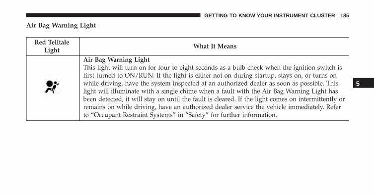
Air Bag Warning Light
Red TelltaleLight
What It Means
Air Bag Warning LightThis light will turn on for four to eight seconds as a bulb check when the ignition switch isfirst turned to ON/RUN. If the light is either not on during startup, stays on, or turns onwhile driving, have the system inspected at an authorized dealer as soon as possible. Thislight will illuminate with a single chime when a fault with the Air Bag Warning Light hasbeen detected, it will stay on until the fault is cleared. If the light comes on intermittently orremains on while driving, have an authorized dealer service the vehicle immediately. Referto “Occupant Restraint Systems” in “Safety” for further information.
5
GETTING TO KNOW YOUR INSTRUMENT CLUSTER 185
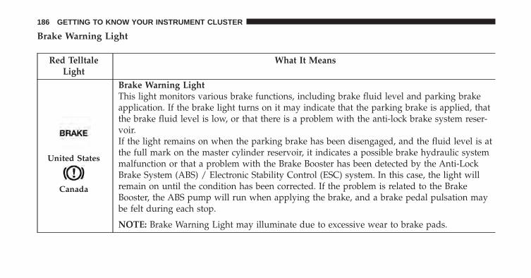
Brake Warning Light
Red TelltaleLight
What It Means
United States
Canada
Brake Warning LightThis light monitors various brake functions, including brake fluid level and parking brakeapplication. If the brake light turns on it may indicate that the parking brake is applied, thatthe brake fluid level is low, or that there is a problem with the anti-lock brake system reser-voir.If the light remains on when the parking brake has been disengaged, and the fluid level is atthe full mark on the master cylinder reservoir, it indicates a possible brake hydraulic systemmalfunction or that a problem with the Brake Booster has been detected by the Anti-LockBrake System (ABS) / Electronic Stability Control (ESC) system. In this case, the light willremain on until the condition has been corrected. If the problem is related to the BrakeBooster, the ABS pump will run when applying the brake, and a brake pedal pulsation maybe felt during each stop.
NOTE: Brake Warning Light may illuminate due to excessive wear to brake pads.
186 GETTING TO KNOW YOUR INSTRUMENT CLUSTER

The dual brake system provides a reserve braking capac-ity in the event of a failure to a portion of the hydraulicsystem. A leak in either half of the dual brake system isindicated by the Brake Warning Light, which will turn onwhen the brake fluid level in the master cylinder hasdropped below a specified level.
The light will remain on until the cause is corrected.
NOTE: The light may flash momentarily during sharpcornering maneuvers, which change fluid level condi-tions. The vehicle should have service performed, andthe brake fluid level checked.
If brake failure is indicated, immediate repair is necessary.
WARNING!
Driving a vehicle with the red brake light on isdangerous. Part of the brake system may have failed.It will take longer to stop the vehicle. You could havea collision. Have the vehicle checked immediately.
Vehicles equipped with the Anti-Lock Brake System(ABS) are also equipped with Electronic Brake ForceDistribution (EBD). In the event of an EBD failure, theBrake Warning Light will turn on along with the ABSLight. Immediate repair to the ABS system is required.
Operation of the Brake Warning Light can be checked byplacing the ignition in the ON/RUN position. The lightshould illuminate for approximately two seconds. The lightshould then turn off unless the parking brake is applied ora brake fault is detected. If the light does not illuminate,have the light inspected by an authorized dealer.
The light also will turn on when the parking brake isapplied with the ignition placed in the ON/RUN posi-tion.
NOTE: This light shows only that the parking brake isapplied. It does not show the degree of brake application.
5
GETTING TO KNOW YOUR INSTRUMENT CLUSTER 187

Vehicle Security Warning Light — If Equipped
Red TelltaleLight
What It Means
Vehicle Security Warning Light — If EquippedThis light will flash at a fast rate for approximately 15 seconds when the vehicle securityalarm is arming, and then will flash slowly until the vehicle is disarmed.
Oil Pressure Warning Light
Red TelltaleLight
What It Means
Oil Pressure Warning LightThis light indicates low engine oil pressure. If the light turns on while driving, stop the ve-hicle and shut off the engine as soon as possible. A chime will sound when this light turnson.Do not operate the vehicle until the cause is corrected. This light does not indicate howmuch oil is in the engine. The engine oil level must be checked under the hood.
188 GETTING TO KNOW YOUR INSTRUMENT CLUSTER

Oil Temperature Warning Light
Red TelltaleLight
What It Means
Oil Temperature Warning LightThis telltale indicates engine oil temperature is high. If the light turns on while driving, stopthe vehicle and shut off the engine as soon as possible.
Battery Charge Warning Light
Red TelltaleLight
What It Means
Battery Charge Warning LightThis light illuminates when the battery is not charging properly. If it stays on while the en-gine is running, there may be a malfunction with the charging system. Contact your autho-rized dealer as soon as possible. This indicates a possible problem with the electrical systemor a related component.If jump starting is required, refer to “Jump Starting” in “In Case Of Emergency.”
5
GETTING TO KNOW YOUR INSTRUMENT CLUSTER 189

Engine Temperature Warning Light
Red TelltaleLight
What It Means
Engine Temperature Warning LightThis light warns of an overheated engine condition. If the engine coolant temperature is toohigh, this indicator will illuminate and a single chime will sound. If the temperature reaches theupper limit, a chime will be sound.If the light turns on while driving, safely pull over and stop the vehicle. If the A/C system is on,turn it off. Also, shift the transmission into NEUTRAL and idle the vehicle. If the temperaturereading does not return to normal, turn the engine off immediately and call for service. Refer to“If Your Engine Overheats” in “In Case Of Emergency” for further information.
190 GETTING TO KNOW YOUR INSTRUMENT CLUSTER

Electric Power Steering Fail Warning Light — If Equipped
Red TelltaleLight
What It Means
Electric Power Steering Fail Warning — If EquippedThis light is used to manage the electrical warning of the EPS (Power Steering System). Re-fer to “Power Steering” in “Starting And Operating” for further information.
Door Open Indicator Light
Red TelltaleLight
What It Means
Door Open Indicator LightThis indicator will illuminate when one or more door(s) are not fully closed.
NOTE: If the vehicle is moving and a door is opened, there will also be a single chime.
5
GETTING TO KNOW YOUR INSTRUMENT CLUSTER 191

Hood Open Warning Light — If Equipped
Red TelltaleLight
What It Means
Hood Open Warning LightThis indicator will illuminate when the hood is ajar/open and not fully closed.
Liftgate Open Warning Light
Red TelltaleLight
What It Means
Liftgate Open Warning LightThis indicator will turn when the liftgate is open.
192 GETTING TO KNOW YOUR INSTRUMENT CLUSTER

Transmission Fault Warning Light
Red TelltaleLight
What It Means
Transmission Fault Warning LightThis light will illuminate (together with a message in the Instrument Cluster Display and abuzzer) to indicate a transmission fault. This light indicates that the transmission fluid tem-perature is running hot. This may occur with severe usage. If this light turns on, safely pullover and stop the vehicle. Then, place the transmission into NEUTRAL and run the engineat idle speed or apply light foot pressure to increase the engine speed RPM until the Trans-mission Temperature light turns off. Contact your authorized dealer if the message remainsafter restarting the engine.
WARNING!
If you continue operating the vehicle when the Trans-mission Temperature Warning Light is illuminated youcould cause the fluid to boil over, come in contact withhot engine or exhaust components and cause a fire.
CAUTION!
Continuous driving with the Transmission Tempera-ture Warning Light illuminated will eventually causesevere transmission damage or transmission failure.
5
GETTING TO KNOW YOUR INSTRUMENT CLUSTER 193
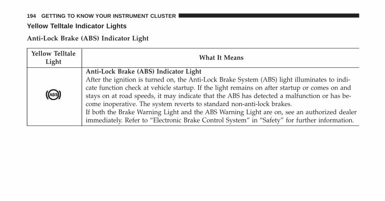
Yellow Telltale Indicator Lights
Anti-Lock Brake (ABS) Indicator Light
Yellow TelltaleLight
What It Means
Anti-Lock Brake (ABS) Indicator LightAfter the ignition is turned on, the Anti-Lock Brake System (ABS) light illuminates to indi-cate function check at vehicle startup. If the light remains on after startup or comes on andstays on at road speeds, it may indicate that the ABS has detected a malfunction or has be-come inoperative. The system reverts to standard non-anti-lock brakes.If both the Brake Warning Light and the ABS Warning Light are on, see an authorized dealerimmediately. Refer to “Electronic Brake Control System” in “Safety” for further information.
194 GETTING TO KNOW YOUR INSTRUMENT CLUSTER

Tire Pressure Monitoring Indicator Light
Yellow TelltaleLight
What It Means
Tire Pressure Monitoring Indicator LightThe warning light switches on and a message is displayed to indicate that the tire pressureis lower than the recommended value and/or that slow pressure loss is occurring. In thesecases, optimal tire duration and fuel consumption may not be guaranteed.Should one or more tires be in the condition mentioned above, the display will show theindications corresponding to each tire in sequence.In any situation in which the message on the display is �See manual�, it is ESSENTIAL torefer to the contents of the �Wheels� paragraph in the �Technical Data� chapter, strictly com-plying with the indications that you find there.
5
GETTING TO KNOW YOUR INSTRUMENT CLUSTER 195

IMPORTANT: Do not continue driving with one or moreflat tires as handling may be compromised. Stop thevehicle, avoiding sharp braking and steering. Repairimmediately using the dedicated tire repair kit andcontact your authorized dealership as soon as possible.
Each tire, including the spare (if provided), should bechecked monthly when cold and inflated to the inflationpressure recommended by the vehicle manufacturer onthe vehicle placard or tire inflation pressure label. If yourvehicle has tires of a different size than the size indicatedon the vehicle placard or tire inflation pressure label, youshould determine the proper tire inflation pressure forthose tires.
As an added safety feature, your vehicle has beenequipped with a Tire Pressure Monitoring System(TPMS) that illuminates a low tire pressure telltale whenone or more of your tires is significantly under-inflated.Accordingly, when the low tire pressure telltale illumi-nates, you should stop and check your tires as soon as
possible and inflate them to the proper pressure. Drivingon a significantly under-inflated tire causes the tire tooverheat and can lead to tire failure. Under-inflation alsoreduces fuel efficiency and tire tread life, and may affectthe vehicle’s handling and stopping ability.
Please note that the TPMS is not a substitute for propertire maintenance, and it is the driver’s responsibility tomaintain correct tire pressure, even if under-inflation hasnot reached the level to trigger illumination of the TPMSlow tire pressure telltale.
Your vehicle has also been equipped with a TPMSmalfunction indicator to indicate when the system isnot operating properly. The TPMS malfunction indi-cator is combined with the low tire pressure telltale.When the system detects a malfunction, the telltalewill flash for approximately one minute and thenremain continuously illuminated. This sequence willcontinue upon subsequent vehicle start-ups as long as
196 GETTING TO KNOW YOUR INSTRUMENT CLUSTER

the malfunction exists. When the malfunction indica-tor is illuminated, the system may not be able to detector signal low tire pressure as intended. TPMS mal-functions may occur for a variety of reasons, includingthe installation of replacement or alternate tires orwheels on the vehicle that prevent the TPMS fromfunctioning properly. Always check the TPMS mal-function telltale after replacing one or more tires orwheels on your vehicle, to ensure that the replacementor alternate tires and wheels allow the TPMS tocontinue to function properly.
CAUTION!
The TPMS has been optimized for the originalequipment tires and wheels. TPMS pressures andwarning have been established for the tire sizeequipped on your vehicle. Undesirable system opera-tion or sensor damage may result when using re-placement equipment that is not of the same size,type, and/or style. Aftermarket wheels can causesensor damage. Using aftermarket tire sealants maycause the Tire Pressure Monitoring System (TPMS)sensor to become inoperable. After using an after-market tire sealant it is recommended that you takeyour vehicle to an authorized dealership to have yoursensor function checked.
5
GETTING TO KNOW YOUR INSTRUMENT CLUSTER 197

Electronic Stability Control (ESC) Indicator Light — If Equipped
Yellow TelltaleLight
What It Means
Electronic Stability Control (ESC) Indicator Light — If EquippedThe “ESC Indicator Light” in the instrument cluster will come on when the ignition isplaced in the ON/RUN position, and when ESC is activated. It should go out with the en-gine running. If the “ESC Indicator Light” comes on continuously with the engine running,a malfunction has been detected in the ESC system. If this light remains on after several ig-nition cycles, and the vehicle has been driven several miles (kilometers) at speeds greaterthan 30 MPH (48 km/h), see your authorized dealer as soon as possible to have the problemdiagnosed and corrected.• The “ESC Off Indicator Light” and the “ESC Indicator Light” come on momentarily each
time the ignition is placed in the ON/RUN position.• Each time the ignition is turned to ON/RUN, the ESC system will be ON, even if it was
turned off previously.• The ESC system will make buzzing or clicking sounds when it is active. This is normal;
the sounds will stop when ESC becomes inactive.• This light will come on when the vehicle is in an ESC event.
198 GETTING TO KNOW YOUR INSTRUMENT CLUSTER

Electronic Stability Control (ESC) OFF IndicatorLight — If Equipped
Yellow TelltaleLight
What It Means
Electronic Stability Control (ESC) OFF Indicator Light — If EquippedThis light indicates the Electronic Stability Control (ESC) is off.
5
GETTING TO KNOW YOUR INSTRUMENT CLUSTER 199

Engine Check/Malfunction Indicator Light (MIL)
Yellow TelltaleLight
What It Means
Engine Check/Malfunction Indicator Light (MIL)The Engine Check/Malfunction Indicator Light (MIL) is a part of an Onboard DiagnosticSystem called OBD II that monitors engine and automatic transmission control systems. Thelight will illuminate when the ignition is in the ON position before engine start. If the bulbdoes not come on when turning the key from OFF to ON/RUN, have the condition checkedpromptly.Certain conditions, such as a loose or missing gas cap, poor quality fuel, etc., may illuminatethe light after engine start. The vehicle should be serviced if the light stays on through sev-eral typical driving styles. In most situations, the vehicle will drive normally and will notrequire towing.When the engine is running, the MIL may flash to alert serious conditions that could lead toimmediate loss of power or severe catalytic converter damage. The vehicle should be ser-viced as soon as possible if this occurs.
200 GETTING TO KNOW YOUR INSTRUMENT CLUSTER

WARNING!
A malfunctioning catalytic converter, as referencedabove, can reach higher temperatures than in normaloperating conditions. This can cause a fire if youdrive slowly or park over flammable substances suchas dry plants, wood, cardboard, etc. This could resultin death or serious injury to the driver, occupants orothers.
CAUTION!
Prolonged driving with the Malfunction IndicatorLight (MIL) on could cause damage to the enginecontrol system. It also could affect fuel economy anddriveability. If the MIL is flashing, severe catalyticconverter damage and power loss will soon occur.Immediate service is required. 5
GETTING TO KNOW YOUR INSTRUMENT CLUSTER 201

Low Fuel Indicator Light
Yellow TelltaleLight
What It Means
Low Fuel Indicator LightWhen the fuel level reaches approximately 1.3–1.8 gal (5–7 L) this light will turn on, and re-main on until fuel is added.
Vehicle Security Indicator Light
Yellow TelltaleLight
What It Means
Vehicle Security Indicator LightThis indicator will illuminate when the Vehicle Security Alarm system has detected an at-tempt was made to break into the vehicle.
202 GETTING TO KNOW YOUR INSTRUMENT CLUSTER

Audio System Failure Light — If Equipped
Yellow TelltaleLight
What It Means
Audio System Failure LightThe telltale illuminates to report a failure of the Audio System.Contact your authorized dealership as soon as possible.
Exterior Bulb Failure Indicator Light
Yellow TelltaleLight
What It Means
Exterior Bulb Failure Indicator LightThis light will illuminate when there is a malfunction in one of the exterior bulbs.
5
GETTING TO KNOW YOUR INSTRUMENT CLUSTER 203

Green Telltale Indicator Lights
Turn Signal Indicator Lights
Green Tell-tale Light
What It Means
Turn Signal Indicator LightsThe instrument cluster arrow will flash independently for the LEFT or RIGHT turn signal as se-lected, as well as the exterior turn signal lamp(s) (front and rear) as selected when the multi-function lever is moved down (LEFT) or up (RIGHT).
Park/Headlight ON Indicator Light
Green TelltaleLight
What It Means
Park/Headlight ON Indicator LightThis indicator will illuminate when the park lights or headlights are turned on.
204 GETTING TO KNOW YOUR INSTRUMENT CLUSTER
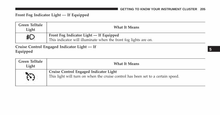
Front Fog Indicator Light — If Equipped
Green TelltaleLight
What It Means
Front Fog Indicator Light — If EquippedThis indicator will illuminate when the front fog lights are on.
Cruise Control Engaged Indicator Light — IfEquipped
Green TelltaleLight
What It Means
Cruise Control Engaged Indicator LightThis light will turn on when the cruise control has been set to a certain speed.
5
GETTING TO KNOW YOUR INSTRUMENT CLUSTER 205

Blue Telltale Indicator Lights
High Beam Indicator Light
Blue TelltaleLight
What It Means
High Beam Indicator LightThis indicator shows that the high beam headlights are on. Push the multifunction controllever away from you to switch the headlights to high beam. Pull the lever toward you toswitch the headlights back to low beam. Pull the lever toward you for a temporary highbeam on, �flash to pass� scenario.
206 GETTING TO KNOW YOUR INSTRUMENT CLUSTER

White Telltale Indicator Lights
Cruise Control Ready Indicator Light
White TelltaleLight
What It Means
Cruise Control Ready Indicator LightThis light will turn on when the electronic speed control is ON, but not set.
Gray Telltale Indicator Light
Cruise Control Cancelled Light
White TelltaleLight
What It Means
Cruise Control Cancelled LightThis light will turn on when the cruise control has been cancelled by the driver. Refer to“Speed Control — If Equipped” in “Starting and Operating” for further information.
5
GETTING TO KNOW YOUR INSTRUMENT CLUSTER 207

ONBOARD DIAGNOSTIC SYSTEM (OBD II)
Your vehicle is equipped with a sophisticated onboarddiagnostic system called OBD II. This system monitorsthe performance of the emissions, engine, and automatictransmission control systems. When these systems areoperating properly, your vehicle will provide excellentperformance and fuel economy, as well as engine emis-sions well within current government regulations.
If any of these systems require service, the OBD II systemwill turn on the “Malfunction Indicator Light (MIL).” Itwill also store diagnostic codes and other information toassist your service technician in making repairs. Al-though your vehicle will usually be drivable and notneed towing, see your authorized dealer for service assoon as possible.
CAUTION!
• Prolonged driving with the MIL on could causefurther damage to the emission control system. Itcould also affect fuel economy and driveability.The vehicle must be serviced before any emissionstests can be performed.
• If the MIL is flashing, while the engine is running,severe catalytic converter damage and power losswill soon occur. Immediate service is required.
Onboard Diagnostic System (OBD II)Cybersecurity
Your vehicle is required to have an Onboard Diagnosticsystem (OBD II) and a connection port to allow access toinformation related to the performance of your emissionscontrols. Authorized service technicians may need toaccess this information to assist with the diagnosis andservice of your vehicle and emissions system.
208 GETTING TO KNOW YOUR INSTRUMENT CLUSTER

WARNING!
• ONLY an authorized service technician should con-nect equipment to the OBD II connection port inorder to diagnose or service your vehicle.
• If unauthorized equipment is connected to theOBD II connection port, such as a driver-behaviortracking device, it may:• Be possible that vehicle systems, including
safety related systems, could be impaired or aloss of vehicle control could occur that may resultin an accident involving serious injury or death.
• Access, or allow others to access, informationstored in your vehicle systems, including per-sonal information.
For further information, refer to “Privacy Practices” and“Uconnect CyberSecurity” in “All About Uconnect Ac-cess” in your Owner’s Manual Radio Supplement and“Cybersecurity” in “Multimedia”.
ELECTRONIC VEHICLE INFORMATION CENTER(EVIC) / DRIVER INFORMATION DISPLAY (DID)
EVIC/DID Description
The vehicle can be equipped with multifunctional dis-play (EVIC), or a reconfigurable multifunctional display(DID), which offers useful information to the driver.
With the ignition in the STOP/OFF position (and the keyremoved, for vehicles with mechanical key), opening/closing of a door will activate the display for viewing,and display the total miles or kilometers in the odometer.
5
GETTING TO KNOW YOUR INSTRUMENT CLUSTER 209

Mapping And Reconfigurable Zone Display (EVIC)— If Equipped
The display shows the following information, if equipped:
• Zone (1)– Date (Centered)
– Compass (Centered)– Time (Centered)– External Temp. (Centered)– Ignition Button — If Equipped
• Zone (2)– Actual Gear Indication (Centered)– PRND (Centered)– Gear Shift Indicator (Centered)
• Zone (3)– Date (Centered)– Compass (Centered)– Time (Centered)– External Temp. (Centered)– Ignition Button — If Equipped (Centered)
Mapping And Reconfigurable Zone Display
210 GETTING TO KNOW YOUR INSTRUMENT CLUSTER

• Zone (4)– Time (Centered)– Title (Centered)– Date (Centered)– Compass (Centered)– Exterior temperature (Centered)
• Zone (4A)– Title (Centered)
• Zone (4B)– Title (Centered)
• Zone (4C)– Title (Centered)– Browsing Arrows (Left)– Title Number (Right)
• Zone (5)– Trip and Fuel Label (Left)
– Trip and Fuel Units (Left)– Trip and Fuel Value (Right)– Trip and Fuel Progress Bar (Centered)– Text (Left)
• Zone (6)– Red Telltale Lights
• Zone (7)– White Telltale Lights
• Zone (8)– Odometer Digits (Left)– Odometer Unit (Right)– Cruise Control Speed Set (Center)– Speed Buzzer (Right)
• Zone (9)– Yellow Telltale Lights
5
GETTING TO KNOW YOUR INSTRUMENT CLUSTER 211

Mapping And Reconfigurable Zone Display (DID)— If Equipped
• Zone (1) – Includes 1A and 1B combined– TRIP Info (Centered)– Speed Display (Centered)
– Compass (Centered)– Ignition Button (Centered)– Exterior Temp (Centered)– Date (Centered)– Time (Centered)
• Zone (1A)– Up and down arrow (Left)– Title number
• Zones (1, 2 & 3)– Date– Compass– Time– Ignition Button (Centered)
• Zone (2)– Double scale (Centered)
Mapping And Reconfigurable Zone Display (DID)
212 GETTING TO KNOW YOUR INSTRUMENT CLUSTER

• Zone (2 & 3)– Ignition Button Info (Centered)– Compass– External Temp– Date– Time
• Zone (4)– Dots
• Zone (5)– Main Area– Subtitle– Instruction
• Zone (6)– Odometer Digits (Left)– Odometer Unit (Right)
• Zone (7)– Red Telltales (Centered)
• Zone (8)– Amber Telltales (Centered)
• Zone (9)– PRND (Centered)– GSI Base
• Zone (10)– Hill Decent Control Telltale (Centered)
• Zone (14)– Cruise Control ICON (Centered)
• Zone (15)– Cruise Control Value (Centered)
• Zone (16)– Passive Speed Limiter
• Zone (17)– Engine Water Temperature Gauge
• Zone (18)– Fuel Gauge
5
GETTING TO KNOW YOUR INSTRUMENT CLUSTER 213

EVIC/DID Control Buttons
The system allows the driver to select information by push-ing the following buttons mounted on the steering wheel:
• UP Arrow Button
Push and release the UP arrow button to scrollupward through the main menu andsubmenus.
• DOWN Arrow Button
Push and release the DOWN arrow button toscroll downward through the main menu andsubmenus.
• RIGHT Arrow Button
Push and release the RIGHT arrow button toaccess the information screens or submenuscreens of a main menu item.
• BACK/LEFT Arrow Button
Push and release the LEFT arrow button toaccess the information screens or submenuscreens of a main menu item.
EVIC/DID Control Buttons
1 — Arrow Up/Down Scroll Through Menus And Submenus2 — Arrow Right/Left Access Information/Submenu Screens3 — OK Button For Selecting And Resetting Information
214 GETTING TO KNOW YOUR INSTRUMENT CLUSTER
• OK Button
The OK button may be used for the following:
Select
Reset (hold)
EVIC/DID Main Menu
The Main Menu is composed of several options that canbe selected using the control buttons above.
NOTE:
• The display mode of the menu items varies dependingon the type of display.
• For some items, a submenu is provided.
• In the Uconnect system, some items on the menu arenot shown on the instrument panel display.
Menu Items
The Menu has the following options:
• Speedometer
• Vehicle Info
• Driver Assist
• Fuel Economy
• Trip
• Audio
• Messages
• Screen Setup
• Settings
5
GETTING TO KNOW YOUR INSTRUMENT CLUSTER 215
Speedometer
Push and release the UP or DOWN arrow buttonuntil “Speedometer” is highlighted in the EVIC/DID.Push the OK button to change the speedometer scalefrom MPH to km/h (km/h to MPH).
Vehicle Info
Push and release the UP or DOWN arrow buttonuntil �Vehicle Info� is highlighted in the EVIC/DID.Push and release the RIGHT arrow button andCoolant Temp will be displayed. Push the RIGHT
or LEFT arrow button to scroll through thefollowing information displays:
• Tire Pressure
View the information relating to the TPMS system (IfEquipped).
• Coolant Temperature
View the engine coolant temperature.
• Trans Temperature
View the trans oil temperature.
• Battery Voltage
View the voltage value (state of charge) of the battery.
• Service — If Equipped
View the service status message(s).
Fuel Economy
This menu item allows you to set the unit of measure-ment for the �Fuel Economy and Range.�
• Range (Miles or km)
• Current Consumption (mpg or L/100km or km/l
• Average Consumption (mpg or L/100km or km/l
Reset procedure shown at the bottom of the display.
216 GETTING TO KNOW YOUR INSTRUMENT CLUSTER

Trip
This menu item allows you to view information about the�Trip Computer.�
The information displayed, for Trip A and for Trip B, are:
• Distance
(Miles or km)
• Average Consumption
(MPG, or l/ 100km or km/l)
• Travel Time
(Hour/Minute) 00.00.00 — If Equipped
Messages
This menu item allows you to display the informationmessages/malfunction stored.
Vehicles With Multi-Functional Display Reconfigu-rable
The background color of the display varies according tothe priorities of the failure:
• Failed Messages with low priority
Displays in yellow
• Failed Messages with high priority
Displays in red
Screen Setup
This menu item allows you to change the position of theinformation on the display.
5
GETTING TO KNOW YOUR INSTRUMENT CLUSTER 217

Display Gears (Vehicles With Reconfigurable Multi-Functional Display And Automatic Transmission)
By selecting this item, you can select the display mode,the particulars relating to the automatic transmission,and choose between the following options:
• �Single digit�
The right side of the display will show the letter concern-ing the automatic transmission gear selector (P,R,N or D)position. After approximately two seconds, the letter willbe displayed in a central position.
• �Full PRND�
(Default): The right side of the display the letters PRND,the position assumed by the gear selector will be high-lighted in the display. During the operation in sequentialmode (�AutoStick�), in place of the letter D, the gear willbe will be displayed.
In The Upper-Left/Top Right
The information relating to the following can be dis-played:
• External temperature
• Ignition Button — If Equipped
• Compass (If Equipped)
• Date (Month/Day)
• Time (Hours/Minutes)
In the central area of the display, you can view all of theinformation listed above as well as the following:
• Compass — If Equipped
• Speed Display (If Equipped)
• Date (Day/Month/Year)
• Time
218 GETTING TO KNOW YOUR INSTRUMENT CLUSTER

• Compass — If Equipped
• Ignition Button — If Equipped
• External Temp — If equipped
• Menu Item
• Distance Traveled A (Trip A)
• Distance Traveled B (Trip B)
Restore Default Settings
Selecting this item, and you can reset and restore thedefault settings.
Settings
This menu item allows you to change the settings for thefollowing:
• Display
• Units
• Clock and Date
• Security
• Safety and Assistance
• Lights
• Doors and Locks
Vehicles Equipped With Multifunctional DisplayReconfigurable: The following menu/submenu itemsare available in the cluster display.
“Display”
By selecting the �Display,� you can access the followingsettings:
• Language: allows you to select the language in whichto display the information/warnings.
5
GETTING TO KNOW YOUR INSTRUMENT CLUSTER 219

�Units Of Measure�
By selecting the item �Units of Measure,� you can selectthe unit of measure to use for displaying various magni-tudes.
Possible options are:
• US
• Metric
• Custom
• Imperial
�Clock & Data�
By selecting the item, �Clock & Date� you can adjust theclock.
Possible options are:
• Set Time: adjust hours/minutes
• Set Format: adjust the time format �12h� (12 hours) or� 24h� (24 hours)
• Set Date: adjust day/month/year
Security
By selecting the item “Security,” you can make thefollowing adjustments:
• Speed Warning:
Set the vehicle speed limit (km/h or MPH), which thedriver is notified through a visual and acoustic signaling(display of a message and a symbol on the display).
When the speed warning is set, the icon should remainvisualized for the same duration time of the pop up. Ifthe driver exceeded the speed set the icon should remainfor however long the vehicle is over the set speed.
Driver may also turn the Speed Warning “OFF” shouldyou choose not to use this feature.
220 GETTING TO KNOW YOUR INSTRUMENT CLUSTER

• Seat Belt Reminder:
This function is only viewable when the Seat Belt Re-minder (SBR) system is active.
• Hill Start Assist:
Activation/Deactivation of the Hill Start Assist system.
• Passenger Air Bag — If Equipped
Front passenger air bag may be enabled or disabled.
�Safety & Assistance�
By selecting the item �Safety & Assistance,� you can makethe following adjustments:
• ParkSense: a selection of the type of informationprovided by ParkSense
• Rear Parks. Vol.: selection of the volume of acousticsignals provided by ParkSense
• ParkSense Vol.: a selection of the volume of acousticsignals provided by ParkSense
• Front Parks. Vol.: selection of the volume of the beepsprovided by ParkSense
• Buzzer Volume
• Maintenance Brakes (If Equipped): activation of theprocedure to carry out braking system maintenance
• Auto Park Brake (If Equipped): enable/disable auto-insertion of the Electric Parking Brake
�Lights�
By selecting the item �Lights,� you can make the follow-ing adjustments:
• Headlight Off Delay: set the delay for headlight shut-off after engine shutoff
5
GETTING TO KNOW YOUR INSTRUMENT CLUSTER 221

• Headlight Sensitivity: adjust the sensitivity of head-light brightness
• Daytime Running Lights: activate/deactivate the day-time running lights
• Cornering lights: activate/deactivate the corneringlights (If Equipped)
• Interior Ambient lights: adjust the level of interiorambient lights
• Greeting Lights: activate / deactivate greeting lights
�Doors & Locks�
By selecting the item �Doors & Locks,� you can make thefollowing adjustments:
• Auto Door Lock: activate/deactivate the automaticlocking of the doors with the vehicle moving
• Auto Unlock On Exit: automatic unlocking of thedoors when exiting the vehicle
• Flash Light with Lock: activate the direction indicatorswhen closing the doors
• Sound Horn With Lock: activate/deactivate the hornwhen pushing the LOCK button on the key fob. Theoptions are �Off,� �First Press,” and �Second Press�
• Horn With Remote Start: activate/deactivate the hornat the Remote Starting of the engine with the key fob
• Remote Door Unlock: allows you to open the driverdoor only on the first push of the UNLOCK button onthe key fob
• Passive Entry (If Equipped) : activate the automaticlocking of the doors
222 GETTING TO KNOW YOUR INSTRUMENT CLUSTER

TRIP COMPUTER
The Trip computer is used to display information on caroperation when the key is turned to the MAR/RUNposition.
This function allows you to define two separate tripscalled “Trip A” and “Trip B” where the car’s �completetrips� are monitored in an independent manner.
Both trips can be reset (reset - start of a new trip). Toperform a reset, push and hold the OK button on thesteering wheel controls.
“Trip A” is used to display the figures relating to:
• Distance Travelled
• Average Consumption
• Travel Time (driving time)
• Average Speed
Quantities Displayed
Distance Travelled
Indicates the distance travelled by the start of the newtrip.
Average Consumption
Represents the average fuel consumption since the startof the new trip.
Average Speed
Represents the average speed since the start of the newtrip.
Travel Time
Elapsed time since the start of the new trip.
5
GETTING TO KNOW YOUR INSTRUMENT CLUSTER 223

OK Button
Short Push Of The Button: display of various parameters.
Long Push Of The Button: reset quantities and begin anew trip.
New trip
Starts after reset:
• �Manual� by pushing the OK button.
• �Automatic� when the �distance� reaches the value is62140 (99999.9 km) or when the �time travel� reachesthe value of 999.59 (999 hours and 59 minutes).
• After each disconnection and reconnection of the bat-tery.
224 GETTING TO KNOW YOUR INSTRUMENT CLUSTER

SAFETY
CONTENTS� BRAKE SYSTEM . . . . . . . . . . . . . . . . . . . . . . .227
� ELECTRONIC BRAKE CONTROL SYSTEM . . . .228
▫ Anti-Lock Brake System (ABS) . . . . . . . . . . . .229
▫ Traction Control System (TCS) . . . . . . . . . . . .232
▫ Brake Assist System (BAS) . . . . . . . . . . . . . . .232
▫ Electronic Roll Mitigation (ERM) . . . . . . . . . .233
▫ Hill Start Assist (HSA) . . . . . . . . . . . . . . . . .234
▫ Hill Descent Control (HDC) —If Equipped . . . . . . . . . . . . . . . . . . . . . . . . .235
▫ Electronic Stability Control (ESC) . . . . . . . . . .238
▫ ESC Activation/Malfunction Indicator LightAnd ESC OFF Indicator Light . . . . . . . . . . . .243
▫ Trailer Sway Control (TSC) — If Equipped . . .244
▫ Dynamic Steering Torque (DST) . . . . . . . . . . .245
� OCCUPANT RESTRAINT SYSTEMS . . . . . . . . .246
▫ Important Safety Precautions . . . . . . . . . . . . .246
▫ Seat Belt Systems . . . . . . . . . . . . . . . . . . . . .247
▫ Supplemental Restraint System (SRS) . . . . . . .262
▫ Child Restraints . . . . . . . . . . . . . . . . . . . . . .280
▫ Transporting Pets . . . . . . . . . . . . . . . . . . . . .301
6

� SAFETY TIPS . . . . . . . . . . . . . . . . . . . . . . . . .301
▫ Transporting Passengers . . . . . . . . . . . . . . . . .301
▫ Exhaust Gas . . . . . . . . . . . . . . . . . . . . . . . . .302
▫ Safety Checks You Should Make InsideThe Vehicle . . . . . . . . . . . . . . . . . . . . . . . . .303
▫ Periodic Safety Checks You Should MakeOutside The Vehicle . . . . . . . . . . . . . . . . . . .305
226 SAFETY

BRAKE SYSTEM
Your vehicle is equipped with dual hydraulic brakesystems. If either of the two hydraulic systems losesnormal capability, the remaining system will still func-tion. However, there will be some loss of overall brakingeffectiveness. This will be evident by increased pedaltravel during application and greater pedal force re-quired to slow or stop the vehicle. In addition, if themalfunction is caused by a leak in the hydraulic system,the “Brake Warning Light” will turn on as the brake fluidlevel drops in the master cylinder.
In the event power assist is lost for any reason (i.e.,repeated brake applications with the engine OFF) thebrakes will still function. However, the effort required tobrake the vehicle will be much greater than that requiredwith the power system operating.
WARNING!
• Riding the brakes can lead to brake failure andpossibly a collision. Driving with your foot restingor riding on the brake pedal can result in abnor-mally high brake temperatures, excessive liningwear, and possible brake damage. You would nothave your full braking capacity in an emergency.
• Driving a vehicle with the “Brake Warning Light”on is dangerous. A significant decrease in brakingperformance or vehicle stability during brakingmay occur. It will take you longer to stop thevehicle or will make your vehicle harder to control.You could have a collision. Have the vehiclechecked immediately.
6
SAFETY 227

ELECTRONIC BRAKE CONTROL SYSTEM
This system enhances directional control and stability ofthe vehicle under various driving conditions. ESC cor-rects for oversteering or understeering of the vehicle byapplying the brake of the appropriate wheel to assist incounteracting the oversteer or understeer condition. En-gine power may also be reduced to help the vehiclemaintain the desired path.
ESC uses sensors in the vehicle to determine the vehiclepath intended by the driver and compares it to the actualpath of the vehicle. When the actual path does not matchthe intended path, ESC applies the brake of the appro-priate wheel to assist in counteracting the oversteer orundersteer condition.
• Oversteer - when the vehicle is turning more thanappropriate for the steering wheel position.
• Understeer - when the vehicle is turning less thanappropriate for the steering wheel position.
The “ESC Activation/Malfunction Indicator Light” lo-cated in the instrument cluster will start to flash as soonas the tires lose traction and the ESC system becomesactive. The “ESC Activation/Malfunction IndicatorLight” also flashes when the TCS is active. If the “ESCActivation/Malfunction Indicator Light” begins to flashduring acceleration, ease up on the accelerator and applyas little throttle as possible. Be sure to adapt your speedand driving to the prevailing road conditions.
WARNING!
• The Electronic Stability Control (ESC) cannot pre-vent the natural laws of physics from acting on thevehicle, nor can it increase the traction afforded byprevailing road conditions. ESC cannot prevent all
(Continued)
228 SAFETY
WARNING! (Continued)accidents, including those resulting from excessivespeed in turns, driving on very slippery surfaces, orhydroplaning. ESC also cannot prevent collisionsresulting from loss of vehicle control due to inap-propriate driver input for the conditions. Only asafe, attentive, and skillful driver can prevent acci-dents. The capabilities of an ESC equipped vehiclemust never be exploited in a reckless or dangerousmanner which could jeopardize the user’s safety orthe safety of others.
• Vehicle modifications, or failure to properly main-tain your vehicle, may change the handling charac-teristics of your vehicle, and may negatively affectthe performance of the ESC system. Changes to thesteering system, suspension, braking system, tiretype and size or wheel size may adversely affect
(Continued)
WARNING! (Continued)ESC performance. Improperly inflated and un-evenly worn tires may also degrade ESC perfor-mance. Any vehicle modification or poor vehiclemaintenance that reduces the effectiveness of theESC system can increase the risk of loss of vehiclecontrol, vehicle rollover, personal injury and death.
Anti-Lock Brake System (ABS)
The Anti-Lock Brake System (ABS) is designed to aid thedriver in maintaining vehicle control under adversebraking conditions. The system operates with a separatecomputer to modulate hydraulic pressure, to preventwheel lock-up and help avoid skidding on slipperysurfaces.
6
SAFETY 229

All vehicle wheels and tires must be the same size andtype, and tires must be properly inflated, to produceaccurate signals for the computer.
WARNING!
Significant over or under-inflation of tires or mixingsizes of tires or wheels on the vehicle can lead to lossof braking effectiveness.
The ABS conducts a low-speed self-test at approximately12 mph (20 km/h). If you have your foot lightly on thebrake while this test is occurring, you may feel slightpedal movement. The movement can be more apparenton ice and snow. This is normal.
The ABS pump motor runs during the self-test at 12 mph(20 km/h) and during an ABS stop. The pump motormakes a low humming noise during operation, which isnormal.
WARNING!
• Pumping of the Anti-Lock Brakes will diminishtheir effectiveness and may lead to a collision.Pumping makes the stopping distance longer. Justpress firmly on your brake pedal when you need toslow down or stop.
• The ABS cannot prevent the natural laws of phys-ics from acting on the vehicle, nor can it increasebraking or steering efficiency beyond that affordedby the condition of the vehicle brakes and tires orthe traction afforded.
• The ABS cannot prevent collisions, including thoseresulting from excessive speed in turns, followinganother vehicle too closely, or hydroplaning.
• The capabilities of an ABS equipped vehicle mustnever be exploited in a reckless or dangerousmanner, which could jeopardize the user’s safety orthe safety of others.
230 SAFETY

CAUTION!
The ABS is subject to possible detrimental effects ofelectronic interference caused by improperly in-stalled aftermarket radios or telephones.
NOTE: During severe braking conditions, a pulsing sen-sation may occur and a clicking noise will be heard. Thisis normal, indicating that the ABS is functioning.
• Do not “ride” the brakes by resting your foot on thepedal. This could overheat the brakes and result inunpredictable braking action, longer stopping dis-tances, or brake damage.
• When descending mountains or hills, repeated brakingcan cause brake fade with loss of braking control.Avoid repeated heavy braking by downshifting thetransmission or locking out overdrive whenever pos-sible.
• Engines may idle at higher speeds during warm-up,which could cause rear wheels to spin and result inloss of vehicle control. Be especially careful whiledriving on slippery roads, in close-quarter maneuver-ing, parking, or stopping.
• Do not drive too fast for road conditions, especiallywhen roads are wet or slushy. A wedge of water canbuild up between the tire tread and the road. Thishydroplaning action can cause loss of traction, brakingability, and control.
• After going through deep water or a car wash, brakesmay become wet, resulting in decreased performanceand unpredictable braking action. Dry the brakes bygentle, intermittent pedal action while driving at veryslow speeds.
6
SAFETY 231

Traction Control System (TCS)
This system monitors the amount of wheel spin of each ofthe driven wheels. If wheel spin is detected, brakepressure is applied to the slipping wheel(s) and enginepower is reduced to provide enhanced acceleration andstability. A feature of the TCS system, Brake LimitedDifferential (BLD), functions similar to a limited slipdifferential and controls the wheel spin across a drivenaxle. If one wheel on a driven axle is spinning faster thanthe other, the system will apply the brake of the spinningwheel. This will allow more engine torque to be appliedto the wheel that is not spinning. This feature remainsactive even if TCS and ESC are in the “Partial Off” modeor the “Full Off” mode. Refer to “Electronic StabilityControl (ESC)” in this section for further information.
Brake Assist System (BAS)
The BAS is designed to optimize the vehicle’s brakingcapability during emergency braking maneuvers. Thesystem detects an emergency braking situation by sens-ing the rate and amount of brake application and thenapplies optimum pressure to the brakes. This can helpreduce braking distances. The BAS complements theAnti-Lock Brake System (ABS). Applying the brakes veryquickly results in the best BAS assistance. To receive thebenefit of the system, you must apply continuous brak-ing pressure during the stopping sequence, (do not“pump” the brakes). Do not reduce brake pedal pressureunless braking is no longer desired. Once the brake pedalis released, the BAS is deactivated.
232 SAFETY

WARNING!
The Brake Assist System (BAS) cannot prevent thenatural laws of physics from acting on the vehicle,nor can it increase the traction afforded by prevailingroad conditions. BAS cannot prevent collisions, in-cluding those resulting from excessive speed inturns, driving on very slippery surfaces, or hydro-planing. The capabilities of a BAS-equipped vehiclemust never be exploited in a reckless or dangerousmanner, which could jeopardize the user’s safety orthe safety of others.
Electronic Roll Mitigation (ERM)
This system anticipates the potential for wheel lift bymonitoring the driver’s steering wheel input and thespeed of the vehicle. When ERM determines that the rateof change of the steering wheel angle and vehicle’s speedare sufficient to potentially cause wheel lift, it then
applies the appropriate brake and may also reduceengine power to lessen the chance that wheel lift willoccur. ERM will only intervene during very severe orevasive driving maneuvers. ERM can only reduce thechance of wheel lift occurring during severe or evasivedriving maneuvers. It cannot prevent wheel lift due toother factors, such as road conditions, leaving the road-way, or striking objects or other vehicles.
NOTE: ERM is disabled anytime the ESC is in “Full Off”mode. Refer to Electronic Stability Control (ESC) in thissection for a complete explanation of the available ESCmodes.
WARNING!
Many factors, such as vehicle loading, road condi-tions, and driving conditions, influence the chancethat wheel lift or rollover may occur. Electronic Roll
(Continued)
6
SAFETY 233

WARNING! (Continued)Mitigation (ERM) cannot prevent all wheel lift orrollovers, especially those that involve leaving theroadway or striking objects or other vehicles. Thecapabilities of an ERM-equipped vehicle must neverbe exploited in a reckless or dangerous manner,which could jeopardize the user’s safety or the safetyof others.
Hill Start Assist (HSA)
The HSA system is designed to help the driver acceleratethe vehicle from a complete stop while on an incline. Ifthe driver releases the brake while stopped on an incline,HSA will continue to hold the brake pressure for a shortperiod. If the driver does not apply the throttle before thistime expires, the system will release brake pressure and
the vehicle will roll down the hill as normal. The systemwill release brake pressure in proportion to amount ofthrottle applied.
The following conditions must be met in order for HSA toactivate:
• The vehicle must be stopped.
• The vehicle must be on a 5% (approximate) grade orgreater hill.
• The gear selection must match vehicle uphill direction(i.e., vehicle facing uphill is in forward gear; vehiclebacking uphill is in REVERSE gear).
• For vehicles equipped with an automatic transmission,the HSA will work in REVERSE gear and all forwardgears. The system will not activate if the transmissionis in PARK.
234 SAFETY

WARNING!
There may be situations where the Hill Start Assist(HSA) will not activate and slight rolling may occur,such as on minor hills or with a loaded vehicle, orwhile pulling a trailer. HSA is not a substitute foractive driving involvement. It is always the driver’sresponsibility to be attentive to distance to othervehicles, people, and objects, and most importantlybrake operation to ensure safe operation of the ve-hicle under all road conditions. Your complete atten-tion is always required while driving to maintainsafe control of your vehicle. Failure to follow thesewarnings can result in a collision or serious personalinjury.
Hill Descent Control (HDC) — If Equipped
HDC is intended for low speed off road driving while in4WD Low Range. HDC maintains vehicle speed whiledescending hills during various driving situations. HDCcontrols vehicle speed by actively controlling the brakes.
Hill Descent Control (Trailhawk)
6
SAFETY 235

HDC has three states:
1. Off (feature is not enabled and will not activate).
2. Enabled (feature is enabled and ready but activationconditions are not met, or driver is actively overridingwith brake or throttle application).
3. Active (feature is enabled and actively controllingvehicle speed).
Enabling HDC
HDC is enabled by pushing the HDC switch, but thefollowing conditions must also be met to enable HDC:
• Driveline is in 4WD Low Range.
• Vehicle speed is below 7.5 mph (12 km/h).
• Electric Park Brake (EPB) is released.
• Driver door is closed.
Activating HDC
Once HDC is enabled, it will activate automatically ifdriven down a grade of sufficient magnitude (greaterthan approximately 8%). The set speed for HDC isselectable by the driver and can be adjusted using brakeand throttle input.
Driver Override:
The driver may override HDC activation with throttle orbrake application at anytime.
Deactivating HDC
HDC will be deactivated but remain available if any ofthe following conditions occur:
• Driver overrides HDC set speed with throttle or brakeapplication.
• Vehicle speed exceeds 7.5 mph (12 km/h) but remainsbelow 25 mph (40 km/h).
236 SAFETY

• Vehicle is on a downhill grade of insufficient magni-tude (less than approximately 8%), is on level ground,or is on an uphill grade.
• Vehicle is shifted to PARK.
Disabling HDC
HDC will be deactivated and disabled if any of thefollowing conditions occur:• The driver pushes the HDC switch.
• The driveline is shifted out of 4WD Low Range.
• Driver door opens.
• The vehicle is driven greater than 25 mph (40 km/h)(HDC exits immediately.)
Feedback To The Driver:
The instrument cluster has an HDC icon and the HDCswitch has an LED which offer feedback to the driverabout the state HDC is in.
• The cluster icon and switch lamp will illuminate andremain solid when HDC is enabled or activated. This isthe normal operating condition for HDC.
• The switch lamp will flash for several seconds thenextinguish when the driver pushes the HDC switchwhen enable conditions have not been met.
The Hill Descent Switch is located within the Selec-Terrain knob in the upper right position.
WARNING!
HDC is only intended to assist the driver in control-ling vehicle speed when descending hills. The drivermust remain attentive to the driving conditions andis responsible for maintaining a safe vehicle speed.
6
SAFETY 237

Electronic Stability Control (ESC)
This system enhances directional control and stability ofthe vehicle under various driving conditions. ESC cor-rects for oversteering or understeering of the vehicle byapplying the brake of the appropriate wheel to assist incounteracting the oversteer or understeer condition. En-gine power may also be reduced to help the vehiclemaintain the desired path.
ESC uses sensors in the vehicle to determine the vehiclepath intended by the driver and compares it to the actualpath of the vehicle. When the actual path does not matchthe intended path, ESC applies the brake of the appro-priate wheel to assist in counteracting the oversteer orundersteer condition.
• Oversteer - when the vehicle is turning more thanappropriate for the steering wheel position.
• Understeer - when the vehicle is turning less thanappropriate for the steering wheel position.
The “ESC Activation/Malfunction Indicator Light” lo-cated in the instrument cluster will start to flash as soonas the tires lose traction and the ESC system becomesactive. The “ESC Activation/Malfunction IndicatorLight” also flashes when the TCS is active. If the “ESCActivation/Malfunction Indicator Light” begins to flashduring acceleration, ease up on the accelerator and applyas little throttle as possible. Be sure to adapt your speedand driving to the prevailing road conditions.
WARNING!
• The Electronic Stability Control (ESC) cannot pre-vent the natural laws of physics from acting on thevehicle, nor can it increase the traction afforded byprevailing road conditions. ESC cannot prevent allaccidents, including those resulting from excessivespeed in turns, driving on very slippery surfaces, or
(Continued)
238 SAFETY

WARNING! (Continued)hydroplaning. ESC also cannot prevent collisionsresulting from loss of vehicle control due to inap-propriate driver input for the conditions. Only asafe, attentive, and skillful driver can prevent acci-dents. The capabilities of an ESC equipped vehiclemust never be exploited in a reckless or dangerousmanner which could jeopardize the user’s safety orthe safety of others.
• Vehicle modifications, or failure to properly main-tain your vehicle, may change the handling charac-teristics of your vehicle, and may negatively affectthe performance of the ESC system. Changes to thesteering system, suspension, braking system, tiretype and size or wheel size may adversely affect
(Continued)
WARNING! (Continued)ESC performance. Improperly inflated and un-evenly worn tires may also degrade ESC perfor-mance. Any vehicle modification or poor vehiclemaintenance that reduces the effectiveness of theESC system can increase the risk of loss of vehiclecontrol, vehicle rollover, personal injury and death.
ESC Operation Modes
To disable ESC and other safety systems, follow theinstruction below.
There are three modes of active safety systems present onthe vehicle:
• ESC On
• Partial Off
• Full Off
6
SAFETY 239

ESC On – Two Wheel Drive Vehicles And Four WheelDrive Vehicles In 2WD And 4WD High Range
This is the normal operating mode for ESC when oper-ating a two-wheel drive vehicle. It is also the normalmode for operating a four-wheel drive vehicle in 2WD or4WD HIGH range. The ESC system will be in “ESC On”mode whenever the vehicle is started or the powertransfer unit (if equipped) is shifted out of 4WD LOWrange. This mode should be used for most drivingsituations. ESC should only be turned to “Partial Off” or“Full Off” for specific reasons as noted. Refer to “PartialOff” and to “Full Off” for additional information.
NOTE: It is recommended to select the mode �Partial Off�or �Full Off� only for specific reasons.
Partial Off – Two Wheel Drive Vehicles And FourWheel Drive Vehicles In 2WD And 4WD High Range
The “Partial Off” mode is intended for driving in deepsnow, sand, or gravel. This mode raises the threshold forTCS and ESC activation, which allows for more wheelspin than what ESC normally allows.
ESC OFF Button
240 SAFETY

To enter the “Partial Off” mode, momentarily push the“ESC Off” button and the ESC Off indicator light willilluminate. To turn the ESC on again, momentarily pushthe ESC OFF button and the ESC Off indicator light willturn off. This will restore the normal “ESC On” mode ofoperation.
NOTE: To improve the vehicle’s traction when drivingwith snow chains, or when starting off in deep snow,sand, or gravel, it may be desirable to switch to the“Partial Off” mode by momentarily pushing the “ESCOff” button. Once the situation requiring “Partial Off”mode is overcome, turn ESC back on by momentarilypushing the “ESC Off” button. This may be done whilethe vehicle is in motion.
WARNING!
• When in “Partial Off” mode, the TCS functionalityof ESC, (except for the limited slip feature de-scribed in the TCS section), has been disabled andthe “ESC Off Indicator Light” will be illuminated.When in “Partial Off” mode, the engine powerreduction feature of TCS is disabled, and theenhanced vehicle stability offered by the ESC sys-tem is reduced.
• Trailer Sway control (TSC) is disabled when theESC system is in the “Partial Off” mode.
Full Off – Four-Wheel Drive Vehicles In 4WD HighAnd 4WD Low Range
The “Full Off” mode is intended for off-highway andoff-road use when ESC stability features could inhibitvehicle maneuverability due to trail conditions. The “ESCOff” button is located in the lower switch bank above the
6
SAFETY 241

climate control panel. To enter “Full Off” mode, push andhold the “ESC Off” button for five seconds while thevehicle is stopped with the engine running. After fiveseconds, the ESC Off indicator light will illuminate andan “ESC Off” message will appear in the odometer.
In this mode, ESC and TCS are turned off (except for the“limited slip” feature described in the TCS section) untilthe vehicle reaches a speed of 40 mph (64 km/h). Atspeeds over 40 mph (64 km/h), the system automaticallyswitches to “Partial Off” mode, described above. Whenthe vehicle speed returns to less than 35 mph (56 km/h),the ESC system will return to “Full Off” mode. The ESCOFF indicator light is always illuminated when ESC isoff. To turn ESC on again, momentarily push the “ESCOff” button. This will restore the normal “ESC On” modeof operation.
NOTE: With the ESC switched off, the enhanced vehiclestability offered by ESC is unavailable. In an emergencyevasive maneuver, the ESC system will not engage toassist in maintaining stability. “Full Off” mode is onlyintended for off-highway or off-road use.
NOTE:
• “Full Off” is the only operating mode for ESC in 4WDLOW range. The ESC system will be in this modewhenever the vehicle is started in 4WD LOW range orthe power transfer unit is shifted into 4WD LOWrange.
• The “ESC OFF” message will display and a chime willsound when the gear selector is moved from anyposition to the PARK position and then moved out ofthe PARK position. This will occur even if the messagewas cleared previously.
242 SAFETY

Selec-Terrain — If Equipped
On models equipped with Selec-Terrain, the activation ofsome driving modes provide partial off or full off of someactive safety systems in order to optimize performance inspecific modes.
Partial or full off of the active safety systems will beindicated by a light in the instrument cluster.
In �SAND� and �MUD�, the active safety systems arepartially disabled and put in place to ensure maximumperformance in the specific mode of operation. However,you can reactivate them completely at any time bypushing the button.
NOTE: In 4WD LOW, the active safety systems arecompletely bypassed in order to ensure maximum off-road performance.
ESC Activation/Malfunction Indicator Light AndESC OFF Indicator Light
The “ESC Activation/Malfunction IndicatorLight” in the instrument cluster will come onwhen the ignition switch is turned to the ONposition. It should go out with the engine
running. If the “ESC Activation/Malfunction IndicatorLight” comes on continuously with the engine running, amalfunction has been detected in the ESC system. If thislight remains on after several ignition cycles, and thevehicle has been driven several miles/kilometers atspeeds greater than 30 mph (48 km/h), see your autho-rized dealer as soon as possible to have the problemdiagnosed and corrected.
6
SAFETY 243

The “ESC Activation/Malfunction Indicator Light” (lo-cated in the instrument cluster) starts to flash as soon asthe tires lose traction and the ESC system becomes active.The “ESC Activation/Malfunction Indicator Light” alsoflashes when Traction Control System is active. If the“ESC Activation/Malfunction Indicator Light” begins toflash during acceleration, ease up on the accelerator andapply as little throttle as possible. Be sure to adapt yourspeed and driving to the prevailing road conditions.
NOTE:
• The “ESC Activation/Malfunction Indicator Light”and the “ESC OFF Indicator Light” come on momen-tarily each time the ignition switch is turned ON.
• Each time the ignition is turned ON, the ESC systemwill be ON even if it was turned off previously.
• The ESC system will make buzzing or clicking soundswhen it is active. This is normal; the sounds will stopwhen ESC becomes inactive following the maneuverthat caused the ESC activation.
The �ESC OFF Indicator Light� indicates theElectronic Stability Control (ESC) is partiallyoff or full off.
The ESC OFF switch is located in the center console.
Trailer Sway Control (TSC) — If Equipped
TSC uses sensors in the vehicle to recognize an exces-sively swaying trailer and will take the appropriateactions to attempt to stop the sway. The system mayreduce engine power and apply the brake of the appro-priate wheel(s) to counteract the sway of the trailer. TSCwill become active automatically once an excessivelyswaying trailer is recognized.
244 SAFETY

NOTE: TSC cannot stop all trailers from swaying. Al-ways use caution when towing a trailer and follow thetrailer tongue weight recommendations. Refer to “TrailerTowing” in “Starting And Operating” for further infor-mation. When TSC is functioning, the “ESC Activation/Malfunction Indicator Light” will flash, the engine powermay be reduced and you may feel the brakes beingapplied to individual wheels to attempt to stop the trailerfrom swaying. TSC is disabled when the ESC system is inthe “Partial Off” mode.
WARNING!
If TSC activates while driving, slow the vehicledown, stop at the nearest safe location, and adjust thetrailer load to eliminate trailer sway.
Dynamic Steering Torque (DST)
The DST function uses the integration of the ESC systemwith the electric power steering to increase the safetylevel of the whole car. In critical situations (understeer-ing, oversteering, braking with different grip conditions),through the DST function the ESC system controls thesteering to implement an additional torque contributionon the steering wheel, to suggest the most correct ma-neuver to the driver. The coordinated action of brakesand steering increases the safety and car control feeling.
NOTE: The DST is a driving aid system and does notreplace the driver’s actions while driving the car.
6
SAFETY 245

OCCUPANT RESTRAINT SYSTEMS
Some of the most important safety features in yourvehicle are the restraint systems:
• Seat Belt Systems
• Supplemental Restraint Systems (SRS) Air Bags
• Child Restraints
Important Safety Precautions
Please pay close attention to the information in thissection. It tells you how to use your restraint systemproperly, to keep you and your passengers as safe aspossible.
Here are some simple steps you can take to minimize therisk of harm from a deploying air bag:
1. Children 12 years old and under should always ridebuckled up in a vehicle with a rear seat.
2. If a child from 2 to 12 years old (not in a rear-facingchild restraint) must ride in the front passenger seat,move the seat as far back as possible and use theproper child restraint. (Refer to “Child Restraints”)
3. Children that are not big enough to wear the vehicleseat belt properly (Refer to �Child Restraints�) shouldbe secured in a vehicle with a rear seat in childrestraints or belt-positioning booster seats. Older chil-dren who do not use child restraints or belt-positioning booster seats should ride properly buckledup in a vehicle with a rear seat.
4. Never allow children to slide the shoulder belt behindthem or under their arm.
5. You should read the instructions provided with yourchild restraint to make sure that you are using it properly.
6. All occupants should always wear their lap andshoulder belts properly.
246 SAFETY
7. The driver and front passenger seats should be movedback as far as practical to allow the Advanced FrontAir Bags room to inflate.
8. Do not lean against the door or window. If yourvehicle has side air bags, and deployment occurs, theside air bags will inflate forcefully into the spacebetween occupants and the door and occupants couldbe injured.
9. If the air bag system in this vehicle needs to bemodified to accommodate a disabled person, contactthe Customer Center. Phone numbers are providedunder �If You Need Assistance.�
WARNING!
• Never place a rear-facing child restraint in front ofan air bag. A deploying Passenger Advanced FrontAir Bag can cause death or serious injury to a child12 years or younger, including a child in a rear-facing child restraint.
• Only use a rear-facing child restraint in a vehiclewith a rear seat.
Seat Belt Systems
Buckle up even though you are an excellent driver, evenon short trips. Someone on the road may be a poor driverand could cause a collision that includes you. This canhappen far away from home or on your own street.
Research has shown that seat belts save lives, and theycan reduce the seriousness of injuries in a collision. Someof the worst injuries happen when people are thrownfrom the vehicle. Seat belts reduce the possibility of
6
SAFETY 247

ejection and the risk of injury caused by striking theinside of the vehicle. Everyone in a motor vehicle shouldbe belted at all times.
Enhanced Seat Belt Use Reminder System(BeltAlert)
Driver and Passenger BeltAlert — If Equipped
BeltAlert is a feature intended to remind the driverand outboard front seat passenger (if equipped withoutboard front passenger seat BeltAlert) to buckletheir seat belts. The Belt Alert feature is active when-ever the ignition switch is in the AVV/START orMAR/RUN position.
Initial Indication
If the driver is unbuckled when the ignition switch is firstturned to the AVV/START or MAR/RUN position, achime will signal for a few seconds. If the driver oroutboard front seat passenger (if equipped with outboard
front passenger seat BeltAlert) is unbuckled when theignition switch is first turned to the AVV/START orMAR/ RUN position the Seat Belt Reminder Light willturn on and remain on until both outboard front seatbelts are buckled. The outboard front passenger seatBeltAlert is not active when the outboard front passengerseat is unoccupied.
BeltAlert Warning Sequence
The BeltAlert warning sequence is activated when thevehicle is moving above a specified vehicle speed rangeand the driver or outboard front seat passenger is un-buckled (the outboard front passenger seat BeltAlert isnot active when the outboard front passenger seat isunoccupied). The BeltAlert warning sequence starts byblinking the Seat Belt Reminder Light and sounding anintermittent chime. Once the BeltAlert warning sequencehas completed, the Seat Belt Reminder Light will remainon until the seat belts are buckled. The BeltAlert warning
248 SAFETY

sequence may repeat based on vehicle speed until thedriver and occupied outboard front seat passenger seatbelts are buckled. The driver should instruct all occu-pants to buckle their seat belts.
Change Of Status
If the driver or outboard front seat passenger (ifequipped with outboard front passenger seat BeltAlert)unbuckles their seat belt while the vehicle is traveling,the BeltAlert warning sequence will begin until the seatbelts are buckled again. The outboard front passengerseat BeltAlert is not active when the outboard frontpassenger seat is unoccupied. BeltAlert may be triggeredwhen an animal or heavy object is on the outboard frontpassenger seat or when the seat is folded flat (ifequipped). It is recommended that pets be restrained inthe rear seat (if equipped) in pet harnesses or pet carriersthat are secured by seat belts, and cargo is properlystowed.
BeltAlert can be activated or deactivated by your autho-rized dealer. FCA US LLC does not recommend deacti-vating BeltAlert.
NOTE: If BeltAlert has been deactivated and the driveror outboard front seat passenger is unbuckled the SeatBelt Reminder Light will turn on and remain on until thedriver and outboard front seat passenger seat belts arebuckled.
Lap/Shoulder Belts
All seating positions in your vehicle are equipped withlap/shoulder belts.
The seat belt webbing retractor will lock only during verysudden stops or collisions. This feature allows the shoul-der part of the seat belt to move freely with you undernormal conditions. However, in a collision the seat beltwill lock and reduce your risk of striking the inside of thevehicle or being thrown out of the vehicle.
6
SAFETY 249

WARNING!
• Relying on the air bags alone could lead to moresevere injuries in a collision. The air bags workwith your seat belt to restrain you properly. Insome collisions, the air bags won’t deploy at all.Always wear your seat belt even though you haveair bags.
• In a collision, you and your passengers can suffermuch greater injuries if you are not properly buck-led up. You can strike the interior of your vehicle orother passengers, or you can be thrown out of thevehicle. Always be sure you and others in yourvehicle are buckled up properly.
• It is dangerous to ride in a cargo area, inside oroutside of a vehicle. In a collision, people riding inthese areas are more likely to be seriously injuredor killed.
(Continued)
WARNING! (Continued)• Do not allow people to ride in any area of your
vehicle that is not equipped with seats and seatbelts.
• Be sure everyone in your vehicle is in a seat andusing a seat belt properly. Occupants, including thedriver, should always wear their seat belt whetheror not an air bag is also provided at their seatingposition to minimize the risk of severe injury ordeath in the event of a crash.
• Wearing your seat belt incorrectly could make yourinjuries in a collision much worse. You mightsuffer internal injuries, or you could even slide outof the seat belt. Follow these instructions to wearyour seat belt safely and to keep your passengerssafe, too.
(Continued)
250 SAFETY

WARNING! (Continued)• Two people should never be belted into a single
seat belt. People belted together can crash into oneanother in a collision, hurting one another badly.Never use a lap/shoulder belt or a lap belt for morethan one person, no matter what their size.
• A lap belt worn too high can increase the risk ofinjury in a collision. The seat belt forces won’t be atthe strong hip and pelvic bones, but across yourabdomen. Always wear the lap part of your seatbelt as low as possible and keep it snug.
• A twisted seat belt may not protect you properly. In acollision, it could even cut into you. Be sure the seatbelt is flat against your body, without twists. If youcan’t straighten a seat belt in your vehicle, take it toyour authorized dealer immediately and have it fixed.
(Continued)
WARNING! (Continued)• A seat belt that is buckled into the wrong buckle
will not protect you properly. The lap portion couldride too high on your body, possibly causing inter-nal injuries. Always buckle your seat belt into thebuckle nearest you.
• A seat belt that is too loose will not protect youproperly. In a sudden stop, you could move too farforward, increasing the possibility of injury. Wearyour seat belt snugly.
• A seat belt that is worn under your arm is dangerous.Your body could strike the inside surfaces of thevehicle in a collision, increasing head and neck injury.A seat belt worn under the arm can cause internalinjuries. Ribs aren’t as strong as shoulder bones. Wearthe seat belt over your shoulder so that your strongestbones will take the force in a collision.
(Continued)
6
SAFETY 251

WARNING! (Continued)• A shoulder belt placed behind you will not protect
you from injury during a collision. You are morelikely to hit your head in a collision if you do notwear your shoulder belt. The lap and shoulder beltare meant to be used together.
• A frayed or torn seat belt could rip apart in acollision and leave you with no protection. Inspectthe seat belt system periodically, checking for cuts,frays, or loose parts. Damaged parts must be re-placed immediately. Do not disassemble or modifythe seat belt system. Seat belt assemblies must bereplaced after a collision.
Lap/Shoulder Belt Operating Instructions
1. Enter the vehicle and close the door. Sit back andadjust the seat.
2. The seat belt latch plate is above the back of the frontseat, and next to your arm in the rear seat (for vehiclesequipped with a rear seat). Grasp the latch plate andpull out the seat belt. Slide the latch plate up thewebbing as far as necessary to allow the seat belt to goaround your lap.
Pulling Out The Latch Plate
252 SAFETY

3. When the seat belt is long enough to fit, insert the latchplate into the buckle until you hear a “click.”
4. Position the lap belt so that it is snug and lies lowacross your hips, below your abdomen. To removeslack in the lap belt portion, pull up on the shoulderbelt. To loosen the lap belt if it is too tight, tilt the latchplate and pull on the lap belt. A snug seat belt reducesthe risk of sliding under the seat belt in a collision.
Inserting Latch Plate Into Buckle Inserting Latch Plate Into Buckle
6
SAFETY 253
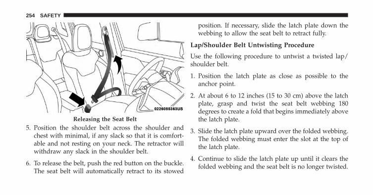
5. Position the shoulder belt across the shoulder andchest with minimal, if any slack so that it is comfort-able and not resting on your neck. The retractor willwithdraw any slack in the shoulder belt.
6. To release the belt, push the red button on the buckle.The seat belt will automatically retract to its stowed
position. If necessary, slide the latch plate down thewebbing to allow the seat belt to retract fully.
Lap/Shoulder Belt Untwisting Procedure
Use the following procedure to untwist a twisted lap/shoulder belt.
1. Position the latch plate as close as possible to theanchor point.
2. At about 6 to 12 inches (15 to 30 cm) above the latchplate, grasp and twist the seat belt webbing 180degrees to create a fold that begins immediately abovethe latch plate.
3. Slide the latch plate upward over the folded webbing.The folded webbing must enter the slot at the top ofthe latch plate.
4. Continue to slide the latch plate up until it clears thefolded webbing and the seat belt is no longer twisted.
Releasing the Seat Belt
254 SAFETY

Adjustable Upper Shoulder Belt Anchorage
In the driver and front passenger seats, the top of theshoulder belt can be adjusted upward or downward toposition the seat belt away from your neck. Push orsqueeze the anchorage button to release the anchorage, andmove it up or down to the position that serves you best.
As a guide, if you are shorter than average, you willprefer the shoulder belt anchorage in a lower position,and if you are taller than average, you will prefer theshoulder belt anchorage in a higher position. After yourelease the anchorage button, try to move it up or downto make sure that it is locked in position.
NOTE: The adjustable upper shoulder belt anchorage isequipped with an Easy Up feature. This feature allowsthe shoulder belt anchorage to be adjusted in the upwardposition without pushing or squeezing the release but-ton. To verify the shoulder belt anchorage is latched, pulldownward on the shoulder belt anchorage until it islocked into position.
Adjustable Anchorage
6
SAFETY 255

WARNING!
• Miss-adjustment of the seat belt could reduce theeffectiveness of the safety belt in a crash. Positionthe shoulder belt across the shoulder and chestwith minimal, if any slack so that it is comfortableand not resting on your neck. The retractor willwithdraw any slack in the shoulder belt.
• Wearing your seat belt incorrectly could make yourinjuries in a collision much worse. You mightsuffer internal injuries, or you could even slide outof the seat belt. Follow these instructions to wearyour seat belt safely and to keep your passengerssafe, too.
Second Row Center Belt Operating Instructions
The second row center seat belt features a seat belt witha mini-latch plate and buckle, which allows the seat beltto detach from the lower anchor when the seat is folded.The mini-latch plate and regular latch plate can then bestored out of the way in the seat for added convenienceto open up utilization of the storage areas behind thefront seats when the seat is not occupied.
1. Remove the mini-latch plate and regular latch platefrom its stowed position on the seat.
2. Grasp the mini-latch plate and pull the seat belt overthe seat.
256 SAFETY

3. Route the shoulder belt to the inside of the left headrestraint.
4. When the seat belt is long enough to fit, insert themini-latch plate into the mini-buckle until you hear a“click.”
5. Sit back in seat. Slide the regular latch plate up thewebbing as far as necessary to allow the seat belt to goaround your lap.
6. When the seat belt is long enough to fit, insert the latchplate into the buckle until you hear a “click.”
Pulling Out The Latch Plate
Inserting Latch Plate Into Buckle
6
SAFETY 257

7. Position the lap belt so that it is snug and lies lowacross your hips, below your abdomen. To removeslack in the lap belt portion, pull up on the shoulderbelt. To loosen the lap belt if it is too tight, pull on thelap belt. A snug seat belt reduces the risk of slidingunder the seat belt in a collision.
8. Position the shoulder belt on your chest so that it iscomfortable and not resting on your neck. The retrac-tor will withdraw any slack in the seat belt.
9. To release the seat belt, push the red button on thebuckle.
10. To disengage the mini-latch plate from the mini-buckle for storage, insert the regular latch plate intothe center red slot on the mini-buckle. The seat beltwill automatically retract to its stowed position. Ifnecessary, slide the latch plate down the webbing to
allow the seat belt to retract fully. Insert the mini-latch plate and regular latch plate into its stowedposition.
WARNING!
• If the mini-latch plate and mini-buckle are notproperly connected when the seat belt is used by anoccupant, the seat belt will not be able to provideproper restraint and will increase the risk of injuryin a collision.
• When reattaching the mini-latch plate and mini-buckle, ensure the seat belt webbing is not twisted.If the webbing is twisted, follow the precedingprocedure to detach the mini-latch plate and mini-buckle, untwist the webbing, and reattach themini-latch plate and mini-buckle.
258 SAFETY

Seat Belts And Pregnant Women
Seat belts must be worn by all occupants includingpregnant women: the risk of injury in the event of anaccident is reduced for the mother and the unborn childif they are wearing a seat belt.
Position the lap belt snug and low below the abdomenand across the strong bones of the hips. Place theshoulder belt across the chest and away from the neck.Never place the shoulder belt behind the back or underthe arm.
Seat Belt Pretensioner
The front seat belt system is equipped with pretensioningdevices that are designed to remove slack from the seatbelt in the event of a collision. These devices mayimprove the performance of the seat belt by removingslack from the seat belt early in a collision. Pretensionerswork for all size occupants, including those in childrestraints.
NOTE: These devices are not a substitute for proper seatbelt placement by the occupant. The seat belt still must beworn snugly and positioned properly.
Pregnant Women And Seat Belts
6
SAFETY 259

The pretensioners are triggered by the Occupant Re-straint Controller (ORC). Like the air bags, the preten-sioners are single use items. A deployed pretensioner ora deployed air bag must be replaced immediately.
Energy Management Feature
This vehicle has a seat belt system with an EnergyManagement feature in the front seating positions thatmay help further reduce the risk of injury in the event ofa collision. This seat belt system has a retractor assemblythat is designed to release webbing in a controlledmanner.
Switchable Automatic Locking Retractor (ALR)
The seat belts in the passenger seating positions areequipped with a Switchable Automatic Locking Retractor(ALR) which is used to secure a child restraint system.For additional information, refer to “Installing ChildRestraints Using The Vehicle Seat Belt” under the “Child
Restraints” section of this manual. The table belowdefines the type of feature for each seating position.
If the passenger seating position is equipped with anALR and is being used for normal usage, only pull theseat belt webbing out far enough to comfortably wrap
ALR Seating Positions
• ALR = Switchable Automatic Locking Retractor
260 SAFETY
around the occupant’s mid-section so as to not activatethe ALR. If the ALR is activated, you will hear a clickingsound as the seat belt retracts. Allow the webbing toretract completely in this case and then carefully pull outonly the amount of webbing necessary to comfortablywrap around the occupant’s mid-section. Slide the latchplate into the buckle until you hear a �click.�
In Automatic Locking Mode, the shoulder belt is auto-matically pre-locked. The seat belt will still retract toremove any slack in the shoulder belt. Use the AutomaticLocking Mode anytime a child restraint is installed in aseating position that has a seat belt with this feature.Children 12 years old and under should always beproperly restrained in a vehicle with a rear seat.
WARNING!
• Never place a rear-facing child restraint in front ofan air bag. A deploying Passenger Advanced FrontAir Bag can cause death or serious injury to a child12 years or younger, including a child in a rear-facing child restraint.
• Only use a rear-facing child restraint in a vehiclewith a rear seat.
How To Engage The Automatic Locking Mode
1. Buckle the combination lap and shoulder belt.
2. Grasp the shoulder portion and pull downward untilthe entire seat belt is extracted.
3. Allow the seat belt to retract. As the seat belt retracts,you will hear a clicking sound. This indicates the seatbelt is now in the Automatic Locking Mode.
6
SAFETY 261

How To Disengage The Automatic Locking Mode
Unbuckle the combination lap/shoulder belt and allow itto retract completely to disengage the Automatic LockingMode and activate the vehicle sensitive (emergency)locking mode.
WARNING!
• The seat belt assembly must be replaced if theswitchable Automatic Locking Retractor (ALR) fea-ture or any other seat belt function is not workingproperly when checked according to the proce-dures in the Service Manual.
• Failure to replace the seat belt assembly couldincrease the risk of injury in collisions.
• Do not use the Automatic Locking Mode to restrainoccupants who are wearing the seat belt or childrenwho are using booster seats. The locked mode is
(Continued)
WARNING! (Continued)only used to install rear-facing or forward-facingchild restraints that have a harness for restrainingthe child.
Supplemental Restraint System (SRS)
Air Bag System Components
Your vehicle may be equipped with the following air bagsystem components:
• Occupant Restraint Controller (ORC)
• Air Bag Warning Light
• Steering Wheel and Column
• Instrument Panel
• Knee Impact Bolsters
• Advanced Front Air Bags
262 SAFETY

• Supplemental Side Air Bags
• Supplemental Knee Air Bags
• Front and Side Impact Sensors
• Seat Belt Pretensioners
• Seat Belt Buckle Switch
• Seat Track Position Sensors
Advanced Front Air Bags
This vehicle has Advanced Front Air Bags and lap/shoulder belt for both the driver and front passenger. Theair bags are supplemental seat belt restraint systems. Thedriver’s Advanced Front Air Bag is mounted in the centerof the steering wheel. The passenger’s Advanced FrontAir Bag is mounted in the instrument panel, above theglove compartment. The words “SRS AIRBAG” or “AIR-BAG” are embossed on the air bag covers.
Advanced Front Air Bag And Knee Impact BolsterLocations
1 — Driver And Passenger Advanced Front Air Bags2 — Driver Knee Impact Bolster/Supplemental Driver Knee AirBag
6
SAFETY 263

WARNING!
• Being too close to the steering wheel or instrumentpanel during Advanced Front Air Bag deploymentcould cause serious injury, including death. Airbags need room to inflate. Sit back, comfortablyextending your arms to reach the steering wheel orinstrument panel.
• Never place a rear-facing child restraint in front ofan air bag. A deploying Passenger Advanced FrontAir Bag can cause death or serious injury to a child12 years or younger, including a child in a rear-facing child restraint.
• Only use a rear-facing child restraint in a vehiclewith a rear seat.
Advanced Front Air Bag Features
The Advanced Front Air Bag system has multistagedriver and front passenger air bags. This system provides
output appropriate to the severity and type of collision asdetermined by the Occupant Restraint Controller (ORC),which may receive information from the front impactsensors or other system components.
The first stage inflator is triggered immediately during animpact that requires air bag deployment. A low energyoutput is used in less severe collisions. A higher energyoutput is used for more severe collisions.
This vehicle may be equipped with driver and/or frontpassenger seat track position sensors that may adjust theinflation rate of the Advanced Front Air Bags based uponseat position.
This vehicle may be equipped with a driver and/or frontpassenger seat belt buckle switch that detects whetherthe driver or front passenger seat belt is buckled. The seatbelt buckle switch may adjust the inflation rate of theAdvanced Front Air Bags.
264 SAFETY
WARNING!
• No objects should be placed over or near the airbag on the instrument panel or steering wheelbecause any such objects could cause harm if thevehicle is in a collision severe enough to cause theair bag to inflate.
• Do not put anything on or around the air bagcovers or attempt to open them manually. You maydamage the air bags and you could be injuredbecause the air bags may no longer be functional.The protective covers for the air bag cushions aredesigned to open only when the air bags areinflating.
• Relying on the air bags alone could lead to moresevere injuries in a collision. The air bags workwith your seat belt to restrain you properly. In
(Continued)
WARNING! (Continued)some collisions, air bags won’t deploy at all. Al-ways wear your seat belts even though you have airbags.
Advanced Front Air Bag Operation
Advanced Front Air Bags are designed to provide addi-tional protection by supplementing the seat belts. Ad-vanced Front Air Bags are not expected to reduce the riskof injury in rear, side, or rollover collisions. The Ad-vanced Front Air Bags will not deploy in all frontalcollisions, including some that may produce substantialvehicle damage — for example, some pole collisions,truck underrides, and angle offset collisions.
On the other hand, depending on the type and location ofimpact, Advanced Front Air Bags may deploy in crasheswith little vehicle front-end damage but that produce asevere initial deceleration.
6
SAFETY 265
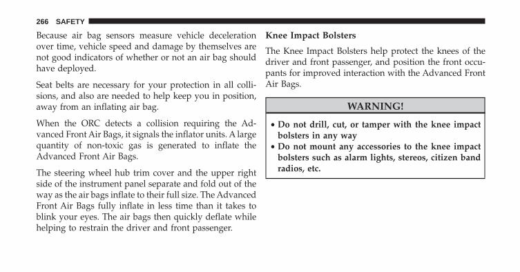
Because air bag sensors measure vehicle decelerationover time, vehicle speed and damage by themselves arenot good indicators of whether or not an air bag shouldhave deployed.
Seat belts are necessary for your protection in all colli-sions, and also are needed to help keep you in position,away from an inflating air bag.
When the ORC detects a collision requiring the Ad-vanced Front Air Bags, it signals the inflator units. A largequantity of non-toxic gas is generated to inflate theAdvanced Front Air Bags.
The steering wheel hub trim cover and the upper rightside of the instrument panel separate and fold out of theway as the air bags inflate to their full size. The AdvancedFront Air Bags fully inflate in less time than it takes toblink your eyes. The air bags then quickly deflate whilehelping to restrain the driver and front passenger.
Knee Impact Bolsters
The Knee Impact Bolsters help protect the knees of thedriver and front passenger, and position the front occu-pants for improved interaction with the Advanced FrontAir Bags.
WARNING!
• Do not drill, cut, or tamper with the knee impactbolsters in any way
• Do not mount any accessories to the knee impactbolsters such as alarm lights, stereos, citizen bandradios, etc.
266 SAFETY

Supplemental Driver Knee Air Bag
This vehicle is equipped with a Supplemental DriverKnee Air Bag mounted in the instrument panel below thesteering column. The Supplemental Driver Knee Air Bagprovides enhanced protection during a frontal impact byworking together with the seat belts, pretensioners, andAdvanced Front Air Bags.
Supplemental Side Air Bags
Your vehicle is equipped with two types of side air bags:
1. Supplemental Seat-Mounted Side Air Bags (SABs):Located in the outboard side of the front seats. TheSABs are marked with a “SRS AIRBAG” or “AIRBAG”label sewn into the outboard side of the seats.
The SABs may help to reduce the risk of occupant injuryduring certain side impacts and/or vehicle rolloverevents, in addition to the injury reduction potentialprovided by the seat belts and body structure.
Front Supplemental Seat-Mounted Side Air Bag
6
SAFETY 267

When the SAB deploys, it opens the seam on the out-board side of the seatback’s trim cover. The inflating SABdeploys through the seat seam into the space between theoccupant and the door. The SAB moves at a very highspeed and with such a high force that it could injureoccupants if they are not seated properly, or if items arepositioned in the area where the SAB inflates. Childrenare at an even greater risk of injury from a deploying airbag.
WARNING!
Do not use accessory seat covers or place objectsbetween you and the Side Air Bags; the performancecould be adversely affected and/or objects could bepushed into you, causing serious injury.
2. Supplemental Side Air Bag Inflatable Curtains(SABICs): Located above the side windows. The trimcovering the SABICs is labeled “SRS AIRBAG” or“AIRBAG.”
Supplemental Side Air Bag Inflatable Curtain (SABIC)Label Location
268 SAFETY

SABICs may help reduce the risk of head or other injuriesto front and rear seat outboard occupants in certain sideimpacts and/or vehicle rollover events, in addition to theinjury reduction potential provided by the seat belts andbody structure.
The SABICs deploy downward, covering the side win-dows. An inflating SABIC pushes the outside edge of thetrim out of the way and covers the window. The SABICsinflate with enough force to injure occupants if they arenot belted and seated properly, or if items are positionedin the area where the SABICs inflate. Children are at aneven greater risk of injury from a deploying air bag.
The SABICs may help reduce the risk of partial orcomplete ejection of vehicle occupants through sidewindows in certain rollover or side impact events.
• The Air Bag Warning Light does not come onduring the four to eight seconds when the ignitionswitch is first in the ON/RUN position.
• The Air Bag Warning Light remains on after the fourto eight-second interval.
• The Air Bag Warning Light comes on intermittentlyor remains on while driving.
Reference the “Air Bag Warning Light” topic in “Supple-mental Restraint System (SRS)” for further information.
WARNING!
• Your vehicle is equipped with left and rightSupplemental Side Air Bag Inflatable Curtains(SABICs). Do not stack luggage or other cargo uphigh enough to block the deployment of theSABICs. The trim covering above the side win-dows where the SABIC and its deployment pathare located should remain free from any obstruc-tions.
(Continued)
6
SAFETY 269

WARNING! (Continued)• Your vehicle is equipped with SABICs. In order for
the SABICs to work as intended, do not install anyaccessory items in your vehicle which could alterthe roof. Do not add an aftermarket sunroof to yourvehicle. Do not add roof racks that require perma-nent attachments (bolts or screws) for installationon the vehicle roof. Do not drill into the roof of thevehicle for any reason.
The SABICs and SABs (“Side Air Bags”) are designed toactivate in certain side impacts and certain rolloverevents. The Occupant Restraint Controller (“ORC”) de-termines whether the deployment of the Side Air Bags ina particular side impact or rollover event is appropriate,based on the severity and type of collision. Vehicledamage by itself is not a good indicator of whether or notSide Air Bags should have deployed.
Side Air Bags are a supplement to the seat belt restraintsystem. Side Air Bags deploy in less time than it takes toblink your eyes.
WARNING!
• Occupants, including children, who are up againstor very close to Side Air Bags can be seriouslyinjured or killed.
• Occupants, including children, should never leanon or sleep against the door, side windows, or areawhere the Side Air Bags inflate, even if they are inan infant or child restraint.
Seat belts (and child restraints where appropriate) arenecessary for your protection in all collisions. They alsohelp keep you in position, away from inflating Side AirBags. To get the best protection from the Side Air Bags,occupants must wear their seat belts properly and situpright with their backs against the seats. Children must
270 SAFETY

be properly restrained in a child restraint or booster seatthat is appropriate for the size of the child.
WARNING!
• Side Air Bags need room to inflate. Do not leanagainst the door or window. Sit upright in thecenter of the seat.
• Being too close to the Side Air Bags during deploy-ment could cause you to be severely injured orkilled.
• Relying on the Side Air Bags alone could lead tomore severe injuries in a collision. The Side AirBags work with your seat belt to restrain youproperly. In some collisions, Side Air Bags won’tdeploy at all. Always wear your seat belt eventhough you have Side Air Bags.
NOTE: Air bag covers may not be obvious in the interiortrim, but they will open during air bag deployment.
Side Impacts
In side impacts, the side impact sensors aid the ORC indetermining the appropriate response to impact events.The system is calibrated to deploy the Side Air Bags onthe impact side of the vehicle during impacts that requireSide Air Bag occupant protection. In side impacts, theSide Air Bags deploy independently; a left side impactdeploys the left Side Air Bags only and a right sideimpact deploys the right Side Air Bags only.
The Side Air Bags will not deploy in all side collisions,including some collisions at certain angles, or some sidecollisions that do not impact the area of the passengercompartment. The Side Air Bags may deploy duringangled or offset frontal collisions where the AdvancedFront Air Bags deploy.
6
SAFETY 271

Rollover Events
Side Air Bags are designed to activate in certain rolloverevents. The ORC determines whether the deployment ofthe Side Air Bags in a particular rollover event is appro-priate, based on the severity and type of collision. Vehicledamage by itself is not a good indicator of whether or notSide Air Bags should have deployed.
The Side Air Bags will not deploy in all rollover events.The rollover sensing system determines if a rolloverevent may be in progress and whether deployment isappropriate. In the event the vehicle experiences a roll-over or near rollover event, and deployment of the SideAir Bags is appropriate, the rollover sensing system willalso deploy the seat belt pretensioners on both sides ofthe vehicle.
If A Deployment Occurs
The Advanced Front Air Bags are designed to deflateimmediately after deployment.
NOTE: Front and/or side air bags will not deploy in allcollisions. This does not mean something is wrong withthe air bag system.
If you have a collision which deploys the air bags, any orall of the following may occur:
• The air bag material may sometimes cause abrasionsand/or skin reddening to the occupants as the air bagsdeploy and unfold. The abrasions are similar to fric-tion rope burns or those you might get sliding along acarpet or gymnasium floor. They are not caused bycontact with chemicals. They are not permanent andnormally heal quickly. However, if you haven’t healedsignificantly within a few days, or if you have anyblistering, see your doctor immediately.
272 SAFETY

• As the air bags deflate, you may see some smoke-likeparticles. The particles are a normal by-product of theprocess that generates the non-toxic gas used for airbag inflation. These airborne particles may irritate theskin, eyes, nose, or throat. If you have skin or eyeirritation, rinse the area with cool water. For nose orthroat irritation, move to fresh air. If the irritationcontinues, see your doctor. If these particles settle onyour clothing, follow the garment manufacturer’s in-structions for cleaning.
Do not drive your vehicle after the air bags have de-ployed. If you are involved in another collision, the airbags will not be in place to protect you.
WARNING!
Deployed air bags and seat belt pretensioners cannotprotect you in another collision. Have the air bags,seat belt pretensioners, and the seat belt retractorassemblies replaced by an authorized dealer imme-diately. Also, have the Occupant Restraint ControllerSystem serviced as well.
NOTE:
• Air bag covers may not be obvious in the interior trim,but they will open during air bag deployment.
• After any collision, the vehicle should be taken to anauthorized dealer immediately.
6
SAFETY 273

Enhanced Accident Response System
In the event of an impact, if the communication networkremains intact, and the power remains intact, dependingon the nature of the event, the ORC will determinewhether to have the Enhanced Accident Response Sys-tem perform the following functions:
• Cut off fuel to the engine.
• Flash hazard lights as long as the battery has power oruntil the hazard light button is pressed. The hazardlights can be deactivated by pressing the hazard lightbutton.
• Turn on the interior lights, which remain on as long asthe battery has power or for 15 minutes from theintervention of the Enhanced Accident Response Sys-tem.
• Unlock the power door locks.
• Turn off the Fuel Pump Heater.
• Turn off the HVAC Blower Motor.
• Close the HVAC Circulation Door.
Enhanced Accident Response System ResetProcedure
After the event occurs, when the system is active, amessage regarding fuel cutoff is displayed. Turn theignition switch from ignition AVV/START or MAR/ACC/ON/RUN to ignition STOP/OFF/LOCK. Care-fully check the vehicle for fuel leaks in the enginecompartment and on the ground near the engine com-partment and fuel tank before resetting the system andstarting the engine.
Depending on the nature of the event the left and rightturn signal lights, located in the instrument panel, mayboth be blinking and will continue to blink. In order to
274 SAFETY

move your vehicle to the side of the road, you mustfollow the system reset procedure.
Customer Action Customer Will See1. Turn Ignition OFF.
(Turn Signal Switch MustBe Placed In Neutral
State).2. Turn Ignition ON. Left Turn Light Is OFF.
Right Turn LightBLINKS.
3. Turn Right Turn SignalSwitch ON.
Right Turn Light Is ONSOLID. Left Turn Light
BLINKS.4. Turn Left Turn Signal
Switch ON.Left Turn Light Is ON
SOLID. Right Turn SignalLight BLINKS.
Customer Action Customer Will See5. Turn Right Turn Signal
Switch ON.Right Turn Light Is ONSOLID. Left Turn Light
BLINKS.6. Turn Left Turn Signal
Switch ON.Left Turn Light Is ON
SOLID. Right Turn LightIs ON SOLID.
7. Turn Left Turn SignalSwitch OFF. (Turn SignalSwitch Must Be Placed In
Neutral State).
Left Turn light Is OFF.Right Turn Light is OFF.
8. Turn Ignition OFF.9. Turn Hazard Flashers
OFF (Manually).System is now reset and
the engine may bestarted.
6
SAFETY 275

If a reset procedure step is not completed within 60seconds, then the turn signal lights will blink and thereset procedure must be performed again in order to besuccessful.
Air Bag Warning Light
The air bags must be ready to inflate for your protectionin a collision. The Occupant Restraint Control-ler (ORC) monitors the internal circuits andinterconnecting wiring associated with air bagsystem electrical components.
The ORC monitors the readiness of the electronic parts ofthe air bag system whenever the ignition switch is in theAVV/START or MAR/ACC/ON/RUN position. If theignition switch is in the STOP/OFF/LOCK position theair bag system is not on and the air bags will not inflate.
The ORC contains a backup power supply system thatmay deploy the air bags even if the battery loses power orit becomes disconnected prior to deployment.
The ORC turns on the Air Bag Warning Light in theinstrument panel for approximately four to eight secondsfor a self-check when the ignition switch is first turned tothe MAR/ACC/ON/RUN position. After the self-check,the Air Bag Warning Light will turn off. If the ORCdetects a malfunction in any part of the system, it turnson the Air Bag Warning Light, either momentarily orcontinuously. A single chime will sound to alert you if thelight comes on again after initial startup.
The ORC also includes diagnostics that will illuminatethe instrument panel Air Bag Warning Light if a malfunc-tion is detected that could affect the air bag system. Thediagnostics also record the nature of the malfunction.While the air bag system is designed to be maintenance
276 SAFETY

free, if any of the following occurs, have an authorizeddealer service the air bag system immediately.
• The Air Bag Warning Light does not come on duringthe four to eight seconds when the ignition switch isfirst turned to the MAR/ACC/ON/RUN position.
• The Air Bag Warning Light remains on after the four toeight-second interval.
• The Air Bag Warning Light comes on intermittently orremains on while driving.
NOTE: If the speedometer, tachometer, or any enginerelated gauges are not working, the Occupant RestraintController (ORC) may also be disabled. In this conditionthe air bags may not be ready to inflate for your protec-tion. Have an authorized dealer service the air bagsystem immediately.
WARNING!
Ignoring the Air Bag Warning Light in your instru-ment panel could mean you won’t have the air bagsto protect you in a collision. If the light does not comeon as a bulb check when the ignition is first turnedon, stays on after you start the vehicle, or if it comeson as you drive, have an authorized dealer service theair bag system immediately.
Redundant Air Bag Warning Light
If a fault with the Air Bag Warning Light is detected,which could affect the Supplemental RestraintSystem (“SRS”), the Redundant Air Bag Warn-ing Light will illuminate on the instrumentpanel. The Redundant Air Bag Warning Light
will stay on until the fault is cleared. In addition, a singlechime will sound to alert you that the Redundant Air BagWarning Light has come on and a fault has been detected.
6
SAFETY 277

If the Redundant Air Bag Warning Light comes onintermittently or remains on while driving have anauthorized dealer service the vehicle immediately. Foradditional information regarding the Redundant Air BagWarning Light refer to “Warning and Indicator Lights” in“Getting to Know Your Instrument Cluster”.
Maintaining Your Air Bag System
WARNING!
• Modifications to any part of the air bag systemcould cause it to fail when you need it. You couldbe injured if the air bag system is not there toprotect you. Do not modify the components orwiring, including adding any kind of badges orstickers to the steering wheel hub trim cover or theupper right side of the instrument panel. Do notmodify the front bumper, vehicle body structure, oradd aftermarket side steps or running boards.
(Continued)
WARNING! (Continued)• It is dangerous to try to repair any part of the air
bag system yourself. Be sure to tell anyone whoworks on your vehicle that it has an air bag system.
• Do not attempt to modify any part of your air bagsystem. The air bag may inflate accidentally or maynot function properly if modifications are made.Take your vehicle to an authorized dealer for anyair bag system service. If your seat, including yourtrim cover and cushion, needs to be serviced in anyway (including removal or loosening/tightening ofseat attachment bolts), take the vehicle to yourauthorized dealer. Only manufacturer approvedseat accessories may be used. If it is necessary tomodify the air bag system for persons with dis-abilities, contact your authorized dealer.
278 SAFETY

Event Data Recorder (EDR)
This vehicle is equipped with an event data recorder(EDR). The main purpose of an EDR is to record, incertain crash or near crash-like situations, such as an airbag deployment or hitting a road obstacle, data that willassist in understanding how a vehicle’s systems per-formed. The EDR is designed to record data related tovehicle dynamics and safety systems for a short period oftime, typically 30 seconds or less. The EDR in this vehicleis designed to record such data as:
• How various systems in your vehicle were operating;
• Whether or not the driver and passenger safety beltswere buckled/fastened;
• How far (if at all) the driver was depressing theaccelerator and/or brake pedal; and,
• How fast the vehicle was traveling.
These data can help provide a better understanding ofthe circumstances in which crashes and injuries occur.
NOTE: EDR data are recorded by your vehicle only if anon-trivial crash situation occurs; no data are recorded bythe EDR under normal driving conditions and no per-sonal data (e.g., name, gender, age, and crash location)are recorded. However, other parties, such as law en-forcement, could combine the EDR data with the type ofpersonally identifying data routinely acquired during acrash investigation.
To read data recorded by an EDR, special equipment isrequired, and access to the vehicle or the EDR is needed.In addition to the vehicle manufacturer, other parties,such as law enforcement, that have the special equip-ment, can read the information if they have access to thevehicle or the EDR.
6
SAFETY 279

Child Restraints
Everyone in your vehicle needs to be buckled up at alltimes, including babies and children. Every state in theUnited States, and every Canadian province, requiresthat small children ride in proper restraint systems. Thisis the law, and you can be prosecuted for ignoring it.
Children 12 years or younger should ride properlybuckled up in a rear seat, if available. According to crashstatistics, children are safer when properly restrained inthe rear seats rather than in the front.
WARNING!
In a collision, an unrestrained child can become aprojectile inside the vehicle. The force required tohold even an infant on your lap could become sogreat that you could not hold the child, no matter
(Continued)
WARNING! (Continued)how strong you are. The child and others could bebadly injured. Any child riding in your vehicleshould be in a proper restraint for the child’s size.
There are different sizes and types of restraints forchildren from newborn size to the child almost largeenough for an adult safety belt. Always check the childseat Owner’s Manual to make sure you have the correctseat for your child. Carefully read and follow all theinstructions and warnings in the child restraint Owner’sManual and on all the labels attached to the childrestraint.
Before buying any restraint system, make sure that it hasa label certifying that it meets all applicable SafetyStandards. You should also make sure that you can installit in the vehicle where you will use it.
280 SAFETY

NOTE:
• For additional information, refer towww.seatcheck.org or call 1-866-732-8243.
• Canadian residents should refer to Transport Cana-da’s website for additional information: www.tc.gc.ca/eng/motorvehiclesafety/safedrivers-childsafety-index-53.htm
Summary Of Recommendations For Restraining Children In Vehicles
Child Size, Height, Weight OrAge
Recommended Type Of ChildRestraint
Infants and Toddlers Children who are two years old oryounger and who have not
reached the height or weight limitsof their child restraint
Either an Infant Carrier or aConvertible Child Restraint, facing
rearward in the rear seat of thevehicle
Small Children Children who are at least twoyears old or who have out-grownthe height or weight limit of their
rear-facing child restraint
Forward-Facing Child Restraintwith a five-point Harness, facing
forward in the rear seat of thevehicle
6
SAFETY 281

Child Size, Height, Weight OrAge
Recommended Type Of ChildRestraint
Larger Children Children who have out-growntheir forward-facing child restraint,
but are too small to properly fitthe vehicle’s seat belt
Belt Positioning Booster Seat andthe vehicle seat belt, seated in the
rear seat of the vehicle
Children Too Large for Child Re-straints
Children 12 years old or younger,who have out-grown the height orweight limit of their booster seat
Vehicle Seat Belt, seated in the rearseat of the vehicle
Infants And Child Restraints
Safety experts recommend that children ride rear-facingin the vehicle until they are two years old or until theyreach either the height or weight limit of their rear-facingchild restraint. Two types of child restraints can be usedrear-facing: infant carriers and convertible child seats.
The infant carrier is only used rear-facing in the vehicle. Itis recommended for children from birth until they reach the
weight or height limit of the infant carrier. Convertiblechild seats can be used either rear-facing or forward-facingin the vehicle. Convertible child seats often have a higherweight limit in the rear-facing direction than infant carriersdo, so they can be used rear-facing by children who haveoutgrown their infant carrier but are still less than at leasttwo years old. Children should remain rear-facing untilthey reach the highest weight or height allowed by theirconvertible child seat.
282 SAFETY

WARNING!
• Never place a rear-facing child restraint in front ofan air bag. A deploying passenger Advanced FrontAir Bag can cause death or serious injury to a child12 years or younger, including a child in a rear-facing child restraint.
• Only use a rear-facing child restraint in a vehiclewith a rear seat.
Older Children And Child Restraints
Children who are two years old or who have outgrowntheir rear-facing convertible child seat can ride forward-facing in the vehicle. Forward-facing child seats andconvertible child seats used in the forward-facing direc-tion are for children who are over two years old or who
have outgrown the rear-facing weight or height limit oftheir rear-facing convertible child seat. Children shouldremain in a forward-facing child seat with a harness foras long as possible, up to the highest weight or heightallowed by the child seat.
All children whose weight or height is above theforward-facing limit for the child seat should use abelt-positioning booster seat until the vehicle’s seat beltsfit properly. If the child cannot sit with knees bent overthe vehicle’s seat cushion while the child’s back is againstthe seatback, they should use a belt-positioning boosterseat. The child and belt-positioning booster seat are heldin the vehicle by the seat belt.
6
SAFETY 283

WARNING!
• Improper installation can lead to failure of aninfant or child restraint. It could come loose in acollision. The child could be badly injured orkilled. Follow the child restraint manufacturer’sdirections exactly when installing an infant orchild restraint.
• After a child restraint is installed in the vehicle, donot move the vehicle seat forward or rearwardbecause it can loosen the child restraint attach-ments. Remove the child restraint before adjustingthe vehicle seat position. When the vehicle seat hasbeen adjusted, reinstall the child restraint.
(Continued)
WARNING! (Continued)• When your child restraint is not in use, secure it in
the vehicle with the seat belt or LATCH anchor-ages, or remove it from the vehicle. Do not leave itloose in the vehicle. In a sudden stop or accident, itcould strike the occupants or seatbacks and causeserious personal injury.
Children Too Large For Booster Seats
Children who are large enough to wear the shoulder beltcomfortably, and whose legs are long enough to bendover the front of the seat when their back is against theseatback, should use the seat belt in a rear seat. Use thissimple 5-step test to decide whether the child can use thevehicle’s seat belt alone:
1. Can the child sit all the way back against the back ofthe vehicle seat?
284 SAFETY
2. Do the child’s knees bend comfortably over the frontof the vehicle seat – while they are still sitting all theway back?
3. Does the shoulder belt cross the child’s shoulderbetween their neck and arm?
4. Is the lap part of the belt as low as possible, touchingthe child’s thighs and not their stomach?
5. Can the child stay seated like this for the whole trip?
If the answer to any of these questions was “no,” then thechild still needs to use a booster seat in this vehicle. If thechild is using the lap/shoulder belt, check seat belt fitperiodically and make sure the seat belt buckle is latched.A child’s squirming or slouching can move the belt out of
position. If the shoulder belt contacts the face or neck,move the child closer to the center of the vehicle, or usea booster seat to position the seat belt on the childcorrectly.
WARNING!
Never allow a child to put the shoulder belt under anarm or behind their back. In a crash, the shoulder beltwill not protect a child properly, which may result inserious injury or death. A child must always wearboth the lap and shoulder portions of the seat beltcorrectly.
6
SAFETY 285

Recommendations For Attaching Child Restraints
Restraint Type CombinedWeight of theChild + Child
Restraint
Use any attachment method shown with an “X” BelowLATCH –
Lower AnchorsOnly
Seat Belt Only LATCH –Lower Anchors
+ Top TetherAnchor
Seat Belt + TopTether Anchor
Rear-FacingChild Restraint
Up to 65 lbs(29.5 kg)
X X
Rear-FacingChild Restraint
More than65 lbs (29.5 kg)
X
Forward-FacingChild Restraint
Up to 65 lbs(29.5 kg)
X X
Forward-FacingChild Restraint
More than65 lbs (29.5 kg)
X
286 SAFETY

Lower Anchors And Tethers For CHildren(LATCH) Restraint System
Your vehicle is equipped with the child restraint anchor-age system called LATCH, which stands for LowerAnchors and Tethers for CHildren. The LATCH systemhas three vehicle anchor points for installing LATCH-equipped child seats. There are two lower anchorageslocated at the back of the seat cushion where it meets theseatback and one top tether anchorage located behind theseating position. These anchorages are used to installLATCH-equipped child seats without using the vehicle’sseat belts. Some seating positions may have a top tetheranchorage but no lower anchorages. In these seatingpositions, the seat belt must be used with the top tetheranchorage to install the child restraint. Please see thefollowing table for more information.
6
SAFETY 287

LATCH Positions For Installing Child Restraints InThis Vehicle
LATCH Positions For Installing Child Restraints In ThisVehicle
• — Lower Anchorage Symbol 2 anchorages perseating position
• — Top Tether Anchorage Symbol
288 SAFETY
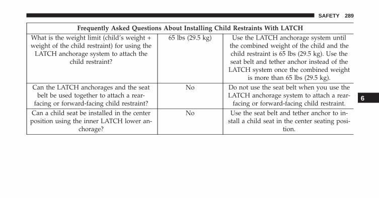
Frequently Asked Questions About Installing Child Restraints With LATCHWhat is the weight limit (child’s weight +weight of the child restraint) for using the
LATCH anchorage system to attach thechild restraint?
65 lbs (29.5 kg) Use the LATCH anchorage system untilthe combined weight of the child and thechild restraint is 65 lbs (29.5 kg). Use theseat belt and tether anchor instead of the
LATCH system once the combined weightis more than 65 lbs (29.5 kg).
Can the LATCH anchorages and the seatbelt be used together to attach a rear-
facing or forward-facing child restraint?
No Do not use the seat belt when you use theLATCH anchorage system to attach a rear-
facing or forward-facing child restraint.Can a child seat be installed in the center
position using the inner LATCH lower an-chorage?
No Use the seat belt and tether anchor to in-stall a child seat in the center seating posi-
tion.
6
SAFETY 289

Frequently Asked Questions About Installing Child Restraints With LATCHCan two child restraints be attached using
a common lower LATCH anchorage?No Never “share” a LATCH anchorage with
two or more child restraints. If the centerposition does not have dedicated LATCHlower anchorages, use the seat belt to in-
stall a child seat in the center position nextto a child seat using the LATCH anchor-
ages in an outboard position.Can the rear-facing child restraint touch
the back of the front passenger seat?Yes The child seat may touch the back of the
front passenger seat if the child restraintmanufacturer also allows contact. See your
child restraint owner’s manual for moreinformation.
Can the head restraints be removed? Yes The head restraints may be removed inevery rear seating position.
290 SAFETY

Locating LATCH Anchorages
The lower anchorages are round bars that arefound at the rear of the seat cushion where itmeets the seatback, below the anchorage sym-bols on the seatback. They are just visible when
you lean into the rear seat to install the child restraint.You will easily feel them if you run your finger along thegap between the seatback and seat cushion.
A — Lower Anchorage Location
6
SAFETY 291
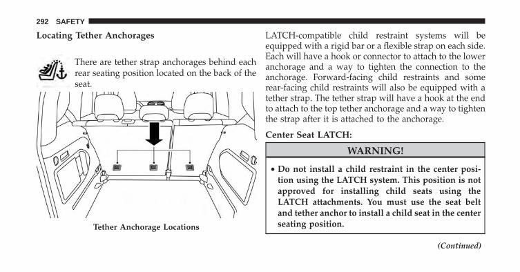
Locating Tether Anchorages
There are tether strap anchorages behind eachrear seating position located on the back of theseat.
LATCH-compatible child restraint systems will beequipped with a rigid bar or a flexible strap on each side.Each will have a hook or connector to attach to the loweranchorage and a way to tighten the connection to theanchorage. Forward-facing child restraints and somerear-facing child restraints will also be equipped with atether strap. The tether strap will have a hook at the endto attach to the top tether anchorage and a way to tightenthe strap after it is attached to the anchorage.
Center Seat LATCH:
WARNING!
• Do not install a child restraint in the center posi-tion using the LATCH system. This position is notapproved for installing child seats using theLATCH attachments. You must use the seat beltand tether anchor to install a child seat in the centerseating position.
(Continued)
Tether Anchorage Locations
292 SAFETY

WARNING! (Continued)• Never use the same lower anchorage to attach more
than one child restraint. Please refer to �InstallingChild Restraints Using the LATCH Lower Anchor-ages� in the section �Installing Child Restraints� fortypical installation instructions.
Always follow the directions of the child restraint manu-facturer when installing your child restraint. Not all childrestraint systems will be installed as described here.
To Install A LATCH-Compatible Child Restraint
If the selected seating position has a Switchable Auto-matic Locking Retractor (ALR) seat belt, stow the seatbelt, following the instructions below. See the section“Installing Child Restraints Using the Vehicle Seat Belt”to check what type of seat belt each seating position has.
1. Loosen the adjusters on the lower straps and on thetether strap of the child seat so that you can moreeasily attach the hooks or connectors to the vehicleanchorages.
2. Place the child seat between the lower anchorages forthat seating position. For some second row seats, youmay need to recline the seat and / or raise the headrestraint to get a better fit. If the rear seat can be movedforward and rearward in the vehicle, you may wish tomove it to its rear-most position to make room for thechild seat. You may also move the front seat forwardto allow more room for the child seat.
3. Attach the lower hooks or connectors of the childrestraint to the lower anchorages in the selected seat-ing position.
6
SAFETY 293

4. If the child restraint has a tether strap, connect it to thetop tether anchorage. See the section “Installing ChildRestraints Using the Top Tether Anchorage” for direc-tions to attach a tether anchor.
5. Tighten all of the straps as you push the child restraintrearward and downward into the seat. Remove slackin the straps according to the child restraint manufac-turer’s instructions.
6. Test that the child restraint is installed tightly bypulling back and forth on the child seat at the beltpath. It should not move more than 1 inch (25.4 mm)in any direction.
How To Stow An Unused Switchable (ALR) SeatBelt:
When using the LATCH attaching system to install achild restraint, stow all ALR seat belts that are not beingused by other occupants or being used to secure childrestraints. An unused belt could injure a child if they playwith it and accidentally lock the seat belt retractor. Beforeinstalling a child restraint using the LATCH system,buckle the seat belt behind the child restraint and out ofthe child’s reach. If the buckled seat belt interferes withthe child restraint installation, instead of buckling itbehind the child restraint, route the seat belt through thechild restraint belt path and then buckle it. Do not lockthe seat belt. Remind all children in the vehicle that theseat belts are not toys and that they should not play withthem.
294 SAFETY
WARNING!
• Improper installation of a child restraint to theLATCH anchorages can lead to failure of the re-straint. The child could be badly injured or killed.Follow the child restraint manufacturer’s directionsexactly when installing an infant or child restraint.
• Child restraint anchorages are designed to with-stand only those loads imposed by correctly-fittedchild restraints. Under no circumstances are they tobe used for adult seat belts, harnesses, or forattaching other items or equipment to the vehicle.
Installing Child Restraints Using The Vehicle SeatBelt
The seat belts in the passenger seating positions areequipped with a Switchable Automatic Locking Retractor(ALR) that is designed to keep the lap portion of the seatbelt tight around the child restraint so that it is notnecessary to use a locking clip. The ALR retractor can be“switched” into a locked mode by pulling all of thewebbing out of the retractor and then letting the webbingretract back into the retractor. If it is locked, the ALR willmake a clicking noise while the webbing is pulled backinto the retractor. Refer to the “Automatic LockingMode” description under “Occupant Restraints” for ad-ditional information on ALR.
6
SAFETY 295

Lap/Shoulder Belt Systems For Installing ChildRestraints In This Vehicle
Lap/Shoulder Belt Systems For Installing ChildRestraints In This Vehicle
• ALR = Switchable Automatic Locking Retractor
• = Top Tether Anchorage Symbol
296 SAFETY

Frequently Asked Questions About Installing Child Restraints With Seat BeltsWhat is the weight limit (child’sweight + weight of the child re-
straint) for using the Tether Anchorwith the seat belt to attach a for-
ward facing child restraint?
Weight limit of the Child Restraint Always use the tether anchor whenusing the seat belt to install a for-ward facing child restraint, up tothe recommended weight limit of
the child restraint.Can the rear-facing child restraint
touch the back of the front passen-ger seat?
Yes Contact between the front passen-ger seat and the child restraint is
allowed, if the child restraintmanufacturer also allows contact.
Can the head restraints be re-moved?
Yes The head restraints should only beremoved by qualified technicians.
If any of the head restraints requireremoval, see your authorized
dealer.Can the buckle stalk be twisted to
tighten the seat belt against the beltpath of the child restraint?
No Do not twist the buckle stalk in aseating position with an ALR re-
tractor.
6
SAFETY 297

Installing A Child Restraint With A SwitchableAutomatic Locking Retractor (ALR)
1. Place the child seat in the center of the seatingposition. For some second row seats, you may need torecline the seat and/or raise the head restraint to get abetter fit. If the rear seat can be moved forward andrearward in the vehicle, you may wish to move it to itsrear-most position to make room for the child seat.You may also move the front seat forward to allowmore room for the child seat.
2. Pull enough of the seat belt webbing from the retractorto pass it through the belt path of the child restraint.Do not twist the belt webbing in the belt path.
3. Slide the latch plate into the buckle until you hear a“click.”
4. Pull on the webbing to make the lap portion tightagainst the child seat.
5. To lock the seat belt, pull down on the shoulder part ofthe belt until you have pulled all the seat belt webbingout of the retractor. Then, allow the webbing to retractback into the retractor. As the webbing retracts, youwill hear a clicking sound. This means the seat belt isnow in the Automatic Locking mode.
6. Try to pull the webbing out of the retractor. If it islocked, you should not be able to pull out any web-bing. If the retractor is not locked, repeat step 5.
7. Finally, pull up on any excess webbing to tighten thelap portion around the child restraint while you pushthe child restraint rearward and downward into thevehicle seat.
8. If the child restraint has a top tether strap and theseating position has a top tether anchorage, connectthe tether strap to the anchorage and tighten the tetherstrap. See the section “Installing Child RestraintsUsing the Top Tether Anchorage” for directions toattach a tether anchor.
298 SAFETY

9. Test that the child restraint is installed tightly bypulling back and forth on the child seat at the beltpath. It should not move more than 1 inch (25.4 mm)in any direction.
Any seat belt system will loosen with time, so check thebelt occasionally, and pull it tight if necessary.
Installing Child Restraints Using The Top TetherAnchorage:
WARNING!
Do not attach a tether strap for a rear-facing car seatto any location in front of the car seat, including theseat frame or a tether anchorage. Only attach thetether strap of a rear-facing car seat to the tetheranchorage that is approved for that seating position,located behind the top of the vehicle seat. See the
(Continued)
WARNING! (Continued)section “Lower Anchors and Tethers for CHildren(LATCH) Restraint System” for the location of ap-proved tether anchorages in your vehicle.
1. Look behind the seating position where you plan toinstall the child restraint to find the tether anchorage.You may need to move the seat forward to providebetter access to the tether anchorage. If there is no toptether anchorage for that seating position, move thechild restraint to another position in the vehicle if oneis available.
6
SAFETY 299
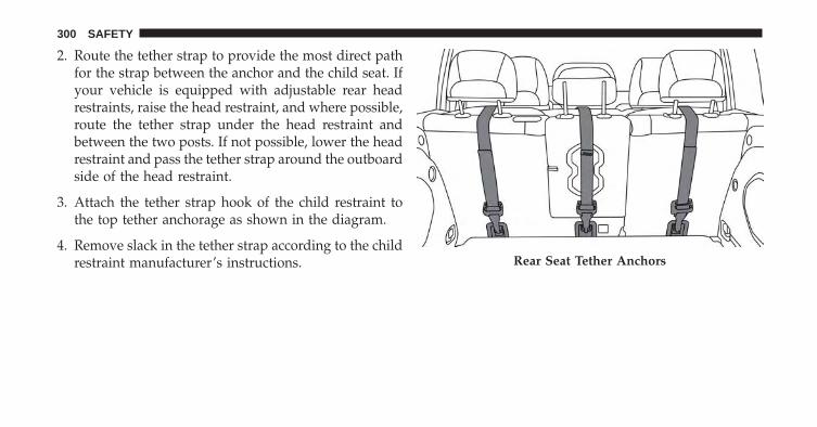
2. Route the tether strap to provide the most direct pathfor the strap between the anchor and the child seat. Ifyour vehicle is equipped with adjustable rear headrestraints, raise the head restraint, and where possible,route the tether strap under the head restraint andbetween the two posts. If not possible, lower the headrestraint and pass the tether strap around the outboardside of the head restraint.
3. Attach the tether strap hook of the child restraint tothe top tether anchorage as shown in the diagram.
4. Remove slack in the tether strap according to the childrestraint manufacturer’s instructions. Rear Seat Tether Anchors
300 SAFETY
WARNING!
• An incorrectly anchored tether strap could lead toincreased head motion and possible injury to thechild. Use only the anchorage position directlybehind the child seat to secure a child restraint toptether strap.
• If your vehicle is equipped with a split rear seat,make sure the tether strap does not slip into theopening between the seatbacks as you removeslack in the strap.
Transporting Pets
Air Bags deploying in the front seat could harm your pet.An unrestrained pet will be thrown about and possiblyinjured, or injure a passenger during panic braking or ina collision.
Pets should be restrained in the rear seat in pet harnessesor pet carriers that are secured by seat belts.
SAFETY TIPS
Transporting Passengers
NEVER TRANSPORT PASSENGERS IN THE CARGOAREA.
WARNING!
• Do not leave children or animals inside parkedvehicles in hot weather. Interior heat build-up maycause serious injury or death.
• It is extremely dangerous to ride in a cargo area,inside or outside of a vehicle. In a collision, peopleriding in these areas are more likely to be seriouslyinjured or killed.
• Do not allow people to ride in any area of yourvehicle that is not equipped with seats and seat belts.
• Be sure everyone in your vehicle is in a seat andusing a seat belt properly.
6
SAFETY 301

Exhaust Gas
WARNING!
Exhaust gases can injure or kill. They contain carbonmonoxide (CO), which is colorless and odorless.Breathing it can make you unconscious and caneventually poison you. To avoid breathing (CO),follow these safety tips:• Do not run the engine in a closed garage or in
confined areas any longer than needed to moveyour vehicle in or out of the area.
• If you are required to drive with the trunk/liftgate/rear doors open, make sure that all windows areclosed and the climate control BLOWER switch isset at high speed. DO NOT use the recirculationmode.
(Continued)
WARNING! (Continued)• If it is necessary to sit in a parked vehicle with the
engine running, adjust your heating or coolingcontrols to force outside air into the vehicle. Set theblower at high speed.
The best protection against carbon monoxide entry intothe vehicle body is a properly maintained engine exhaustsystem.
Whenever a change is noticed in the sound of the exhaustsystem, when exhaust fumes can be detected inside thevehicle, or when the underside or rear of the vehicle isdamaged, have a competent mechanic inspect the com-plete exhaust system and adjacent body areas for broken,damaged, deteriorated, or mispositioned parts. Openseams or loose connections could permit exhaust fumesto seep into the passenger compartment. In addition,inspect the exhaust system each time the vehicle is raisedfor lubrication or oil change. Replace as required.
302 SAFETY

Safety Checks You Should Make Inside TheVehicle
Seat Belts
Inspect the seat belt system periodically, checking for cuts,frays, and loose parts. Damaged parts must be replacedimmediately. Do not disassemble or modify the system.
Front seat belt assemblies must be replaced after acollision. Rear seat belt assemblies must be replaced aftera collision if they have been damaged (i.e., bent retractor,torn webbing, etc.). If there is any question regarding seatbelt or retractor condition, replace the seat belt.
Air Bag Warning Light
The Air Bag warning light will turn on for four toeight seconds as a bulb check when the ignition switchis first turned to ON/RUN. If the light is either not onduring starting, stays on, or turns on while driving,have the system inspected at an authorized dealer as
soon as possible. This light will illuminate with asingle chime when a fault with the Air Bag WarningLight has been detected, it will stay on until the faultis cleared. If the light comes on intermittently orremains on while driving, have an authorized dealerservice the vehicle immediately. Refer to “OccupantRestraints” in “Safety” for further information.
Defroster
Check operation by selecting the defrost mode and placethe blower control on high speed. You should be able to feelthe air directed against the windshield. See your autho-rized dealer for service if your defroster is inoperable.
Floor Mat Safety Information
Always use floor mats designed to fit the footwell of yourvehicle. Use only floor mats that leave the pedal areaunobstructed and that are firmly secured so that theycannot slip out of position and interfere with the pedalsor impair safe operation of your vehicle in other ways.
6
SAFETY 303

WARNING!
Pedals that cannot move freely can cause loss ofvehicle control and increase the risk of serious per-sonal injury.• Always make sure that floor mats are properly
attached to the floor mat fasteners.• Never place or install floor mats or other floor
coverings in the vehicle that cannot be properlysecured to prevent them from moving and interfer-ing with the pedals or the ability to control thevehicle.
• Never put floor mats or other floor coverings on topof already installed floor mats. Additional floormats and other coverings will reduce the size of thepedal area and interfere with the pedals.
(Continued)
WARNING! (Continued)• Check mounting of mats on a regular basis. Always
properly reinstall and secure floor mats that havebeen removed for cleaning.
• Always make sure that objects cannot fall into thedriver footwell while the vehicle is moving. Ob-jects can become trapped under the brake pedaland accelerator pedal causing a loss of vehiclecontrol.
• If required, mounting posts must be properly in-stalled, if not equipped from the factory.
Failure to properly follow floor mat installation ormounting can cause interference with the brakepedal and accelerator pedal operation causing loss ofcontrol of the vehicle.
304 SAFETY

Periodic Safety Checks You Should Make OutsideThe Vehicle
Tires
Examine tires for excessive tread wear and uneven wearpatterns. Check for stones, nails, glass, or other objectslodged in the tread or sidewall. Inspect the tread for cutsand cracks. Inspect sidewalls for cuts, cracks, and bulges.Check the wheel nuts for tightness. Check the tires(including spare) for proper cold inflation pressure.
Lights
Have someone observe the operation of brake lights andexterior lights while you work the controls. Check turnsignal and high beam indicator lights on the instrumentpanel.
Door Latches
Check for proper closing, latching, and locking.
Fluid Leaks
Check area under vehicle after overnight parking for fuel,engine coolant, oil, or other fluid leaks. Also, if gasolinefumes are detected, or if fuel or brake fluid leaks aresuspected, the cause should be located and correctedimmediately.
6
SAFETY 305


STARTING AND OPERATING
CONTENTS� STARTING THE ENGINE . . . . . . . . . . . . . . . . .311
▫ Tip Start Feature . . . . . . . . . . . . . . . . . . . . . .312
▫ If Engine Fails To Start . . . . . . . . . . . . . . . . .312
▫ Cold Weather Operation . . . . . . . . . . . . . . . .314
▫ Extended Park Starting. . . . . . . . . . . . . . . . . .314
▫ After Starting — Warming Up The Engine . . . .315
▫ Stopping The Engine . . . . . . . . . . . . . . . . . . .315
▫ Turbocharger “Cool Down” —If Equipped. . . . . . . . . . . . . . . . . . . . . . . . . .316
� ENGINE BREAK-IN RECOMMENDATIONS . . .316
� ELECTRIC PARK BRAKE (EPB) . . . . . . . . . . . .317
▫ Auto Park Brake . . . . . . . . . . . . . . . . . . . . . .321
▫ SafeHold . . . . . . . . . . . . . . . . . . . . . . . . . . .322
▫ Brake Service Mode . . . . . . . . . . . . . . . . . . . .323
� MANUAL TRANSMISSION . . . . . . . . . . . . . . .324
▫ Shifting. . . . . . . . . . . . . . . . . . . . . . . . . . . . .325
▫ Downshifting . . . . . . . . . . . . . . . . . . . . . . . .326
� NINE SPEED AUTOMATIC TRANSMISSION . .328
▫ Gear Selector. . . . . . . . . . . . . . . . . . . . . . . . .330
▫ Gear Ranges . . . . . . . . . . . . . . . . . . . . . . . . .332
7

▫ Transmission Limp Home Mode . . . . . . . . . . .338
▫ Key Ignition Park Interlock. . . . . . . . . . . . . . .339
▫ Brake/Transmission Shift Interlock System. . . .339
� SPEED CONTROL — IF EQUIPPED . . . . . . . . .340
▫ Activation . . . . . . . . . . . . . . . . . . . . . . . . . . .341
▫ Setting A Desired Speed . . . . . . . . . . . . . . . . .341
▫ Deactivation . . . . . . . . . . . . . . . . . . . . . . . . .342
▫ Resume Speed. . . . . . . . . . . . . . . . . . . . . . . .342
▫ Varying The Speed. . . . . . . . . . . . . . . . . . . . .342
▫ Accelerating For Passing . . . . . . . . . . . . . . . .343
� FOUR WHEEL DRIVE — JEEP ACTIVE DRIVE(4WD) AND JEEP ACTIVE DRIVE LOW(4WD LOW). . . . . . . . . . . . . . . . . . . . . . . . . . .344
▫ Four Wheel Drive (4x4) . . . . . . . . . . . . . . . . .344
� SELEC-TERRAIN . . . . . . . . . . . . . . . . . . . . . . .347
▫ Mode Selection Guide . . . . . . . . . . . . . . . . . .347
� FORWARD COLLISION WARNING (FCW)WITH MITIGATION — IF EQUIPPED . . . . . . .349
▫ Forward Collision Warning (FCW) WithMitigation Operation — If Equipped . . . . . . .349
▫ Turning FCW ON Or OFF . . . . . . . . . . . . . . .352
▫ Changing FCW Sensitivity . . . . . . . . . . . . . . .353
▫ FCW Limited Warning . . . . . . . . . . . . . . . . . .354
▫ Service FCW Warning . . . . . . . . . . . . . . . . . .354
▫ Precautions While Driving With FCW . . . . . . .355
▫ General Information . . . . . . . . . . . . . . . . . . .358
� LANESENSE — IF EQUIPPED . . . . . . . . . . . . .359
▫ LaneSense Operation . . . . . . . . . . . . . . . . . . .359
308 STARTING AND OPERATING

▫ Turning LaneSense ON Or OFF. . . . . . . . . . . .360
▫ LaneSense Warning Message. . . . . . . . . . . . . .360
▫ Changing LaneSense Status . . . . . . . . . . . . . .368
� REAR PARKSENSE — IF EQUIPPED . . . . . . . .369
▫ Rear ParkSense Sensors . . . . . . . . . . . . . . . . .369
▫ Enabling And Disabling Rear ParkSense . . . . .371
▫ Service The Rear ParkSense System . . . . . . . . .372
▫ ParkSense System Usage Precautions . . . . . . . .373
� REAR BACK UP CAMERA — IF EQUIPPED . . .375
� TIRE PRESSURE MONITOR SYSTEM (TPMS) . .378
▫ Base System . . . . . . . . . . . . . . . . . . . . . . . . .381
▫ Premium System — If Equipped . . . . . . . . . . .383
▫ General Information. . . . . . . . . . . . . . . . . . . .388
� FUEL REQUIREMENTS . . . . . . . . . . . . . . . . . .388
▫ 1.4L Turbo Engine . . . . . . . . . . . . . . . . . . . . .388
▫ 2.4L Engine . . . . . . . . . . . . . . . . . . . . . . . . . .389
▫ Reformulated Gasoline . . . . . . . . . . . . . . . . .389
▫ Gasoline/Oxygenate Blends . . . . . . . . . . . . . .390
▫ E-85 Usage In Non-Flex Fuel Vehicles . . . . . . .390
▫ MMT In Gasoline . . . . . . . . . . . . . . . . . . . . .391
▫ Materials Added To Fuel . . . . . . . . . . . . . . . .391
▫ Fuel System Cautions. . . . . . . . . . . . . . . . . . .392
▫ Carbon Monoxide Warnings . . . . . . . . . . . . .393
� ADDING FUEL . . . . . . . . . . . . . . . . . . . . . . . .393
� VEHICLE LOADING . . . . . . . . . . . . . . . . . . . .397
▫ Certification Label . . . . . . . . . . . . . . . . . . . .397
7
STARTING AND OPERATING 309

� ON-ROAD DRIVING TIPS . . . . . . . . . . . . . . . .399
� OFF-ROAD DRIVING TIPS . . . . . . . . . . . . . . . .400
▫ When To Use 4WD LOW Range . . . . . . . . . . .400
▫ Driving Through Water . . . . . . . . . . . . . . . . .400
▫ Driving In Snow, Mud And Sand . . . . . . . . . .401
▫ Hill Climbing . . . . . . . . . . . . . . . . . . . . . . . .402
▫ Traction Downhill . . . . . . . . . . . . . . . . . . . . .403
▫ After Driving Off-Road . . . . . . . . . . . . . . . . .403
� POWER STEERING . . . . . . . . . . . . . . . . . . . . .404
� TRAILER TOWING . . . . . . . . . . . . . . . . . . . . .405
▫ Common Towing Definitions . . . . . . . . . . . . .405
▫ Trailer Hitch Classification . . . . . . . . . . . . . . .408
▫ Trailer Towing Weights(Maximum Trailer Weight Ratings) . . . . . . . . .409
▫ Trailer And Tongue Weight . . . . . . . . . . . . . .410
▫ Towing Requirements . . . . . . . . . . . . . . . . . .411
▫ Towing Tips . . . . . . . . . . . . . . . . . . . . . . . . .416
� RECREATIONAL TOWING. . . . . . . . . . . . . . . .418
▫ Towing This Vehicle Behind Another Vehicle . .418
▫ Recreational Towing. . . . . . . . . . . . . . . . . . . .419
310 STARTING AND OPERATING

STARTING THE ENGINE
Before starting your vehicle, adjust your seat, adjust theinside and outside mirrors, fasten your seat belt, and ifpresent, instruct all other occupants to buckle their seatbelts.
WARNING!
• Never leave children alone in a vehicle, or withaccess to an unlocked vehicle.
• Allowing children to be in a vehicle unattended isdangerous for a number of reasons. A child orothers could be seriously or fatally injured. Chil-dren should be warned not to touch the parkingbrake, brake pedal or the gear selector.
• Do not leave the key fob in or near the vehicle (orin a location accessible to children), and do notleave the ignition of a vehicle equipped with
(Continued)
WARNING! (Continued)Keyless Enter-N-Go in the MAR/RUN mode. Achild could operate power windows, other controls,or move the vehicle.
Start the engine with the gear selector in the NEUTRALor PARK position. Apply the brake before shifting to anydriving range.
Manual Transmission
Proceed as follows:
1. Set the Electric Park Brake (EPB) and put the gearselector in the NEUTRAL position.
2. Press the clutch pedal to the floor, without pressing theaccelerator.
3. Cycle the ignition to the AVV/START position andrelease it as soon as the engine is started.
7
STARTING AND OPERATING 311

4. If the engine does not start, place the ignition in theSTOP/OFF position and wait 10-15 seconds beforeattempting to restart the engine.
Automatic Transmission
Proceed as follows:
1. Set the Electric Park Brake (EPB) and put the gearselector in the PARK or NEUTRAL position.
2. Press on the brake pedal, without pressing the accel-erator.
3. Cycle the ignition to the AVV/START position andrelease it as soon as the engine is started.
4. If the engine does not start, place the ignition in theSTOP/OFF position and wait 10-15 seconds beforeattempting to restart the engine.
Tip Start Feature
Do not press the accelerator. Cycle the ignition switchbriefly to the AVV/START position and release it. Thestarter motor will continue to run but will automaticallydisengage when the engine is running.
If Engine Fails To Start
WARNING!
Never pour fuel or other flammable liquid into thethrottle body air inlet opening in an attempt to startthe vehicle. This could result in flash fire causingserious personal injury.
If the engine fails to start after you have followed the�Normal Starting� or �Extreme Cold Weather� procedure,and has not experienced an extended park condition asidentified in �Extended Park Starting� procedure it maybe flooded. Push the accelerator pedal all the way to the
312 STARTING AND OPERATING

floor and hold it there. Crank the engine for no more than15 seconds. This should clear any excess fuel in case theengine is flooded. Leave the ignition key in the MAR/RUN position, release the accelerator pedal and repeatthe “Normal Starting” procedure.
CAUTION!
To prevent damage to the starter, do not continuouslycrank the engine for more than 25 seconds at a time.Wait 60 seconds before trying again.
WARNING!
• Never pour fuel or other flammable liquid into thethrottle body air inlet opening in an attempt to startthe vehicle. This could result in flash fire causingserious personal injury.
(Continued)
WARNING! (Continued)• Do not attempt to push or tow your vehicle to get it
started. Vehicles equipped with an automatic trans-mission cannot be started this way. Unburned fuelcould enter the catalytic converter and once theengine has started, ignite and damage the converterand vehicle.
• If the vehicle has a discharged battery, boostercables may be used to obtain a start from a boosterbattery or the battery in another vehicle. This typeof start can be dangerous if done improperly. Referto “Jump-Starting” in “In Case Of Emergency” forfurther information.
7
STARTING AND OPERATING 313

Cold Weather Operation
To ensure reliable starting under extreme cold conditionsan externally powered electric block heater (availablefrom your authorized dealer) is required for the 1.4LTurbo engine below -20°F (-29°C) and for the 2.4L enginebelow -29°F (-34°C) and is recommended for the 2.4Lengine below -20°F (-29°C).
To prevent possible engine damage while starting at lowtemperatures, this vehicle will inhibit engine crankingwhen the ambient temperature is less than -34°F (-35°C)and the oil temperature sensor reading indicates anengine block heater has not been used. The message“plug in engine heater” will be displayed in the instru-ment cluster when the ambient temperature is below -4°F(-20°C) at the time the engine is shut off as a reminder toavoid possible crank delays at the next cold start.
Extended Park Starting
NOTE: Extended Park condition occurs when the vehiclehas not been started or driven for at least 30 days.
1. Install a battery charger or jumper cables to the batteryto ensure a full battery charge during the crank cycle.
2. Cycle the ignition in the START position and release itwhen the engine starts.
3. If the engine fails to start within 10 to 15 seconds, cyclethe ignition to the STOP (OFF/LOCK) position, waitfive seconds to allow the starter to cool, then repeat theExtended Park Starting procedure.
4. If the engine fails to start after eight attempts, allowthe starter to cool for at least 10 minutes, then repeatthe procedure.
314 STARTING AND OPERATING

CAUTION!
To prevent damage to the starter, do not crank con-tinuously for more than 10 seconds at a time. Wait 10to 15 seconds before trying again.
After Starting — Warming Up The Engine
Proceed as follows:
• Travel slowly, letting the engine run at a reduced RPM,without accelerating suddenly.
• It is recommended to wait until the engine coolanttemperature gauge starts to rise for maximum perfor-mance.
Stopping The Engine
Vehicles Equipped With A Mechanical Key Fob:
To turn off the engine with, proceed as follows:
1. Park the car in a position that does not cause a traffichazard.
2. Place the transmission in gear (models with a manualtransmission) or place the transmission in PARK (P)(models with automatic transmission).
3. With the engine idling, place the ignition in theSTOP/OFF position.
4. Remove the key from the ignition when the engine isshut off.
7
STARTING AND OPERATING 315

Vehicles Equipped With Electronic Key (Keyless Enter-N-Go):
To shut off the engine with vehicle speed greater than5 mph (8 km/h), you must push and hold the ignition orpush the START/STOP button three times consecutivelywithin a few seconds. The engine will shut down, and theignition will be placed in the RUN position.
Turning Off the car (placing the ignition from the RUNposition to the STOP position), the power supply to theaccessories are maintained for a period of three minutes.
Opening the driver side door with the ignition in RUNwill sound a short chime that reminds the driver to placethe ignition to STOP.
When the ignition is in the STOP/OFF position, thewindow switches remains active for three minutes.Opening a front door will cancel this function.
After severe driving, idle the engine to allow the tem-perature inside the engine compartment to cool beforeshutting off the engine.
Turbocharger “Cool Down” — If Equipped
This vehicle is equipped with an after-run pump to coolthe turbocharger after the engine is shut off. Dependingon the type of driving and the amount of cargo, the pumpwill run for up to 10 minutes after the engine has beenshut off to circulate coolant through the turbocharger.Although the pump is rubber-mounted for quiet opera-tion, it is normal to hear it running during this time.
ENGINE BREAK-IN RECOMMENDATIONS
A long break-in period is not required for the engine anddrivetrain (transmission and axle) in your vehicle.
Drive moderately during the first 300 miles (500 km).After the initial 60 miles (100 km), speeds up to 50 or55 mph (80 or 90 km/h) are desirable.
316 STARTING AND OPERATING

While cruising, brief full-throttle acceleration within thelimits of local traffic laws contributes to a good break-in.Wide-open throttle acceleration in low gear can be detri-mental and should be avoided.
The engine oil installed in the engine at the factory is ahigh-quality energy conserving type lubricant. Oilchanges should be consistent with anticipated climateconditions under which vehicle operations will occur. Forthe recommended viscosity and quality grades, refer to“Maintenance Procedures” in “Maintaining And CaringFor Your Vehicle.”
CAUTION!
Never use Non-Detergent Oil or Straight Mineral Oilin the engine or damage may result.
NOTE: A new engine may consume some oil during itsfirst few thousand miles (kilometers) of operation. Thisshould be considered a normal part of the break-in andnot interpreted as a problem.
ELECTRIC PARK BRAKE (EPB)
Your vehicle is equipped with an Electric Park BrakeSystem (EPB) that offers simple operation, and someadditional features that make the parking brake moreconvenient and useful.
The parking brake is primarily intended to prevent thevehicle from rolling while parked. Before leaving thevehicle, make sure that the parking brake is applied.Also, be certain to leave the transmission in PARK.
The EPB switch is located in the center console.
7
STARTING AND OPERATING 317

You can engage the EPB in two ways;
• Manually, by applying the park brake switch.
• Automatically, by enabling the Auto Park Brake fea-ture in the customer programmable features section ofthe Uconnect settings or in “Safe Hold” conditions.
To apply the EPB manually, pull up on the switchmomentarily. You may hear a slight whirring sound fromthe back of the vehicle while the EPB engages. Once theparking brake is fully engaged, the BRAKE warninglamp in the instrument cluster and an indicator on theswitch will illuminate. If your foot is on the brake pedalwhile you apply the EPB, you may notice a small amountof brake pedal movement. The EPB can be applied evenwhen the ignition switch is in the STOP/OFF positionbut the BRAKE warning lamp will not illuminate, how-ever, it can only be released when the ignition switch is inthe MAR/RUN position.
NOTE: The EPB fault lamp will illuminate if the EPBswitch is held for longer than 10 seconds (static condi-tions) or 30 seconds (dynamic conditions) in either thereleased or applied position. The light will extinguishupon releasing the switch.
Electric Park Brake Switch
318 STARTING AND OPERATING
If the Auto Park Brake feature is enabled, the EPB willautomatically engage whenever the transmission ismoved into PARK, or with a manual transmission, whenthe ignition switch is in the STOP/OFF position. If yourfoot is on the brake pedal, you may notice a small amountof brake pedal movement while the EPB is engaging.
The electric park brake will be automatically released ifthe driver’s seat belt is buckled and driver’s intention tostart (in forward or reverse direction) is recognized by thesystem
To release the EPB manually, the ignition switch must bein the MAR/RUN position. Put your foot on the brakepedal, then push the EPB switch down momentarily. Youmay hear a slight whirring sound from the back of the carwhile the parking brake disengages. You may also noticea small amount of movement in the brake pedal. Once
the EPB is fully disengaged, The BRAKE warning lampin the instrument cluster and the LED indicator on theswitch will extinguish.
NOTE:
• When parking on a hill, it is important to turn the frontwheels toward the curb on a downhill grade and awayfrom the curb on an uphill grade. Apply the EPBbefore placing the gear selector in PARK, otherwise theload on the transmission locking mechanism maymake it difficult to move the gear selector out of PARK.The EPB should always be applied whenever thedriver is not in the vehicle.
• If the clutch pedal is released at the same time the gaspedal is pressed, the EPB will be automatically re-leased (manual transmissions only).
7
STARTING AND OPERATING 319

WARNING!
• When leaving the vehicle, always remove the key fobfrom the ignition and lock your vehicle. If equippedwith Keyless Enter-N-Go, always make sure the key-less ignition node is in “OFF” mode, remove the keyfob from the vehicle and lock the vehicle
• Never leave children alone in a vehicle, or withaccess to an unlocked vehicle. Allowing children tobe in a vehicle unattended is dangerous for anumber of reasons. A child or others could beseriously or fatally injured. Children should bewarned not to touch the parking brake, brake pedalor the transmission gear selector.
• Do not leave the key fob in or near the vehicle (orin a location accessible to children), and do notleave the ignition of a vehicle equipped withKeyless Enter-N-Go in the ACC or ON/RUN mode.
(Continued)
WARNING! (Continued)A child could operate power windows, other con-trols, or move the vehicle.
• Be sure the parking brake is fully disengagedbefore driving; failure to do so can lead to brakefailure and a collision.
• Always fully apply the parking brake when leav-ing your vehicle, or it may roll and cause damage orinjury. Also be certain to leave the transmission inPARK. Failure to do so may allow the vehicle to rolland cause damage or injury.
CAUTION!
If the Brake System Warning Light remains on withthe parking brake released, a brake system malfunc-tion is indicated. Have the brake system serviced byan authorized dealer immediately.
320 STARTING AND OPERATING

If exceptional circumstances should make it necessary toengage the EPB while the vehicle is in motion, maintainupward pressure on the EPB switch for as long asengagement is desired. The brake warning lamp couldilluminate in case of the hydraulic system is not available.The rear stop lamps will also be illuminated automati-cally while the vehicle remains in motion.
To disengage the EPB while the vehicle is in motion,release the switch. If the vehicle is brought to a completestop using the EPB, when the vehicle reaches approxi-mately 1.9 mph (3 km/h) the EPB will remain engaged.
WARNING!
Driving the vehicle with the parking brake engaged,or repeated use of the parking brake to slow thevehicle may cause serious damage to the brake sys-tem. Be sure the parking brake is fully disengaged
(Continued)
WARNING! (Continued)before driving; failure to do so can lead to brakefailure and a collision.
In the unlikely event of a malfunction of the EPB system,a yellow EPB fault lamp will illuminate. This may beaccompanied by the Brake warning lamp flashing. In thisstatus some EPB functionalities may be deactivated. Inthis event, urgent service of the EPB system is required.Do not rely on the EPB to hold the vehicle stationary.
Auto Park Brake
The EPB can be programmed to be applied automaticallywhenever the vehicle speed is below 1.9 mph (3 km/h) andthe automatic transmission is placed in PARK, or with amanual transmission, whenever the ignition switch is inthe STOP/OFF position. Auto Park Brake is enabled anddisabled by customer selection through the CustomerProgrammable Features section of the Uconnect Settings.
7
STARTING AND OPERATING 321

Any single Auto Park Brake application can be bypassedby pushing the EPB switch to the release position whilethe transmission is placed in PARK (automatic transmis-sion) and the ignition is in the MAR/RUN position.
SafeHold
SafeHold is a safety feature of the EPB system that willengage the park brake automatically if the vehicle is leftunsecured while the ignition switch is in MAR/RUN.
For automatic transmissions, the EPB will automaticallyengage if all of the following conditions are met:
• Vehicle speed is below 1.9 mph (3 km/h).
• There is no attempt to depress the brake pedal oraccelerator pedal.
• The seat belt is unbuckled.
• The driver door is open.
• The vehicle is not in the PARK position.
For manual transmissions, the EPB will automaticallyengage if all of the following conditions are met:
• Vehicle speed is below 1.9 mph (3 km/h).
• There is no attempt to depress the brake pedal oraccelerator pedal.
• The clutch pedal is not pressed.
• The seat belt is unbuckled.
• The driver door is open.
SafeHold can be temporarily bypassed by pushing theEPB Switch while the driver door is open and the brakepedal is pressed. Once manually bypassed, SafeHold willbe enabled again once the vehicle reaches 12 mph(20 km/h) or the ignition is turned to the STOP/OFFposition and back to MAR/RUN again.
322 STARTING AND OPERATING

Brake Service Mode
We recommend having your brakes serviced by yourauthorized dealer. You should only make repairs forwhich you have the knowledge and the right equipment.You should only enter Brake Service Mode during brakeservice.
When servicing your rear brakes, it may be necessary foryou or your technician to push the rear piston into therear caliper bore. With the electric park brake system, thiscan only be done after retracting the EPB actuator. Theactuator retraction can be done easily by entering theBrake Service Mode through the Uconnect Settings inyour vehicle. This menu based system will guide youthrough the steps necessary to retract the EPB actuator inorder to perform rear brake service.
Service Mode has requirements that must be met in orderto be activated:
• The vehicle must be at a standstill.
• The parking brake must be disabled.
• The transmission must be in park or neutral.
• The EPB switch not activated.
• The vehicle in ignition MAR/ON position.
• The brake pedal not pressed.
While in service mode, the EPB fault lamp will flashcontinuously while the ignition switch is MAR/ON.
NOTE: A dedicated message will appear in the EVIC ifBrake Service Mode cannot be activated.
When brake service work is complete, the following stepsmust be followed to reset the parking brake system tonormal operation:
• Ensure the vehicle is at a standstill.
• Press the brake pedal with moderate force.
• Apply the EPB Switch.
7
STARTING AND OPERATING 323
NOTE: A dedicated message will appear in the EVIC ifBrake Service Mode cannot be deactivated.
WARNING!
You can be badly injured working on or around amotor vehicle. Do only that service work for whichyou have the knowledge and the right equipment. Ifyou have any doubt about your ability to perform aservice job, take your vehicle to a competent me-chanic.
MANUAL TRANSMISSION
WARNING!
You or others could be injured if you leave thevehicle unattended without having the parkingbrake fully applied. The parking brake should al-ways be applied when the driver is not in the vehicle,especially on an incline.
CAUTION!
Never drive with your foot resting on the clutchpedal, or attempt to hold the vehicle on a hill with theclutch pedal partially engaged, as this will causeabnormal wear on the clutch.
NOTE: During cold weather, you may experience in-creased effort in shifting until the transmission fluidwarms up. This is normal.
324 STARTING AND OPERATING

To shift the gears, press the clutch pedal to the floor andput the gear selector to the desired position (the diagramfor the engagement of the gears is displayed on thehandle of the lever).
To engage REVERSE gear from the NEUTRAL position,lift the REVERSE ring, located below the knob andsimultaneously move the lever to the left and thenforward.
Shifting
Fully press the clutch pedal before shifting gears. As yourelease the clutch pedal, lightly press the acceleratorpedal.
You should always use first gear when starting from astanding position.
Recommended Vehicle Shift Speeds
To utilize your manual transmission efficiently for fueleconomy and performance, it should be upshifted aslisted in the recommended shift speed chart. Shift at thevehicle speeds listed for acceleration. When heavilyloaded or pulling a trailer, these recommended up-shiftspeeds may not apply.
REVERSE Ring
7
STARTING AND OPERATING 325

Manual Transmission Shift Speeds in MPH (KM/H)All Engines Gear Selection 2 to 3 3 to 4 4 to 5 5 to 6
Accel. 24 (39) 34 (55) 47 (76) 56 (90)Cruise 19 (31) 27 (43) 37 (60) 41 (66)
Downshifting
Moving from a high gear down to a lower gear isrecommended to preserve brakes when driving downsteep hills. In addition, downshifting at the right timeprovides better acceleration when you desire to resumespeed. Downshift progressively. Do not skip gears toavoid overspeeding the engine and clutch.
WARNING!
Do not downshift for additional engine braking on aslippery surface. The drive wheels could lose theirgrip, and the vehicle could skid.
CAUTION!
• Skipping gears and downshifting into lower gearsat higher vehicle speeds can damage the engineand clutch systems, Any attempt to shift into lowergear with clutch pedal depressed may result dam-age to the clutch system. Shifting into lower gearand releasing the clutch may result in enginedamage.
• When descending a hill, be very careful to down-shift one gear at a time to prevent overspeeding theengine which can cause engine damage, and/or
(Continued)
326 STARTING AND OPERATING

CAUTION! (Continued)clutch damage, even if the clutch pedal is pressed.If transfer case is in low range the vehicle speeds tocause engine and clutch damage are significantlylower.
• Failure to follow the maximum recommendeddownshifting speeds may cause the engine damageand/or damage the clutch, even if the clutch pedalis pressed.
• Descending a hill in low range with clutch pedaldepressed could result in clutch damage.
Maximum Recommended Downshift Speeds
CAUTION!
Failure to follow the maximum recommended down-shifting speeds may cause the engine to overspeedand/or damage the clutch disc, even if the clutchpedal is pressed.
Manual Transmission Shift Speeds in MPH (KM/H)Gear Selection 6 to 5 5 to 4 4 to 3 3 to 2 2 to 1
MaximumSpeed
80 (129) 70 (113) 50 (81) 30 (48) 15 (24)
7
STARTING AND OPERATING 327

CAUTION!
If you skip a gear while downshifting or downshiftat too high of a vehicle speed, these conditions maycause the engine to overspeed if too low of a gear isselected and the clutch pedal is released. Damage tothe clutch and the transmission can result fromskipping a gear while downshifting or downshiftingat too high of a vehicle speed even if the clutch pedalis held pressed (i.e., not released).
NINE SPEED AUTOMATIC TRANSMISSION
Your vehicle is equipped with a state of the art, fuelefficient nine-speed transmission.
The transmission gear range (PRND) is displayed besidethe gear selector and in the Electronic Vehicle Informa-tion Center (EVIC)/Driver Information Display (DID). Toselect a gear range, push the lock button on the gear
selector and move the lever rearward or forward. Youmust also press the brake pedal to shift the transmissionout of PARK, or to shift from NEUTRAL into DRIVE orREVERSE when the vehicle is stopped or moving at lowspeeds (refer to �Brake/Transmission Shift Interlock Sys-tem� in this section). Select the DRIVE range for normaldriving.
The electronically-controlled transmission provides aprecise shift schedule. The transmission electronics areself-calibrating; therefore, the first few shifts on a newvehicle may be somewhat abrupt. This is a normalcondition, and precision shifts will develop within a fewhundred miles (kilometers).
WARNING!
• It is dangerous to shift out of PARK or NEUTRALif the engine speed is higher than idle speed. If
(Continued)
328 STARTING AND OPERATING

WARNING! (Continued)your foot is not firmly pressing the brake pedal, thevehicle could accelerate quickly forward or in RE-VERSE. You could lose control of the vehicle andhit someone or something. Only shift into gearwhen the engine is idling normally and your foot isfirmly pressing the brake pedal.
• Unintended movement of a vehicle could injurethose in or near the vehicle. As with all vehicles,you should never exit a vehicle while the engine isrunning. Before exiting a vehicle, always apply theparking brake, shift the transmission into PARK,turn the engine STOP/OFF, and remove the keyfob. When the ignition is in the STOP/OFF (keyremoval) position, the transmission is locked inPARK, securing the vehicle against unwantedmovement.
(Continued)
WARNING! (Continued)• When leaving the vehicle, always make sure the
ignition is in the STOP/OFF position, remove thekey fob from the vehicle, and lock the vehicle.
• Never leave children alone in a vehicle, or withaccess to an unlocked vehicle. Allowing children tobe in a vehicle unattended is dangerous for anumber of reasons. A child or others could beseriously or fatally injured. Children should bewarned not to touch the parking brake, brake pedalor the transmission gear selector.
• Do not leave the key fob in or near the vehicle (orin a location accessible to children), and do notleave the ignition (of a vehicle equipped withKeyless Enter-N-Go) in the MAR/RUN position. Achild could operate power windows, other controls,or move the vehicle.
7
STARTING AND OPERATING 329

CAUTION!
Damage to the transmission may occur if the follow-ing precautions are not observed:• Shift into or out of PARK or REVERSE only after
the vehicle has come to a complete stop.• Do not shift between PARK, REVERSE, NEU-
TRAL, or DRIVE when the engine is above idlespeed.
• Before shifting into any gear, make sure your footis firmly pressing the brake pedal.
NOTE: You must press and hold the brake pedal whileshifting out of PARK.
Gear Selector
The transmission gear selector has PARK, REVERSE,NEUTRAL, DRIVE, and AutoStick (+/-) shift positions.Manual shifts can be made using the AutoStick shiftcontrol (refer to “AutoStick” in this section for furtherinformation). Toggling the gear selector forward (-) orrearward (+) while in the AutoStick position (beside theDRIVE position) will manually select the transmissiongear, and will display the current gear in the instrumentcluster as 1, 2, 3, etc.
NOTE: If the gear selector cannot be moved to the PARK,REVERSE, or NEUTRAL position (when pushed for-ward) it is probably in the AutoStick (+/-) position(beside the DRIVE position). In AutoStick mode, thetransmission gear (1, 2, 3, etc.) is displayed in theinstrument cluster. Move the gear selector to the right(into the DRIVE [D] position) for access to PARK, RE-VERSE, and NEUTRAL.
330 STARTING AND OPERATING
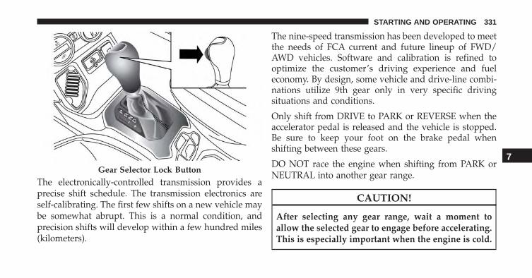
The electronically-controlled transmission provides aprecise shift schedule. The transmission electronics areself-calibrating. The first few shifts on a new vehicle maybe somewhat abrupt. This is a normal condition, andprecision shifts will develop within a few hundred miles(kilometers).
The nine-speed transmission has been developed to meetthe needs of FCA current and future lineup of FWD/AWD vehicles. Software and calibration is refined tooptimize the customer’s driving experience and fueleconomy. By design, some vehicle and drive-line combi-nations utilize 9th gear only in very specific drivingsituations and conditions.
Only shift from DRIVE to PARK or REVERSE when theaccelerator pedal is released and the vehicle is stopped.Be sure to keep your foot on the brake pedal whenshifting between these gears.
DO NOT race the engine when shifting from PARK orNEUTRAL into another gear range.
CAUTION!
After selecting any gear range, wait a moment toallow the selected gear to engage before accelerating.This is especially important when the engine is cold.
Gear Selector Lock Button
7
STARTING AND OPERATING 331

Gear Ranges
PARK (P)
This range supplements the Electric Park Brake (EPB) bylocking the transmission. The engine can be started inthis range. Never attempt to use PARK while the vehicleis in motion. Apply the EPB when leaving the vehicle inthis range.
When parking on a level surface, you may shift thetransmission into PARK first, and then apply the EPB.
When parking on a hill, apply the EPB before shifting thetransmission to PARK, otherwise the load on the trans-mission locking mechanism may make it difficult tomove the gear selector out of PARK. As an addedprecaution, turn the front wheels toward the curb on adownhill grade and away from the curb on an uphillgrade.
WARNING!• Never use the PARK position as a substitute for the
Electric Parking Brake (EPB). Always apply theEPB fully when parked to guard against vehiclemovement and possible injury or damage.
• Your vehicle could move and injure you and othersif it is not completely in PARK. Check by trying tomove the gear selector out of PARK with the brakepedal released. Make sure the transmission is inPARK before leaving the vehicle.
• It is dangerous to shift out of PARK or NEUTRALif the engine speed is higher than idle speed. Ifyour foot is not firmly pressing the brake pedal, thevehicle could accelerate quickly forward or in RE-VERSE. You could lose control of the vehicle andhit someone or something. Only shift into gearwhen the engine is idling normally and your foot isfirmly pressing the brake pedal.
(Continued)
332 STARTING AND OPERATING

WARNING! (Continued)• Unintended movement of a vehicle could injure
those in or near the vehicle. As with all vehicles,you should never exit a vehicle while the engine isrunning. Before exiting a vehicle, always apply theEPB, shift the transmission into PARK, turn theengine OFF, and remove the key fob. When theignition is in the STOP/OFF (key removal) posi-tion, the transmission is locked in PARK, securingthe vehicle against unwanted movement.
• When leaving the vehicle, always make sure theignition is in the STOP/OFF position, remove thekey fob from the vehicle, and lock the vehicle.
(Continued)
WARNING! (Continued)• Never leave children alone in a vehicle, or with
access to an unlocked vehicle. Allowing children tobe in a vehicle unattended is dangerous for anumber of reasons. A child or others could beseriously or fatally injured. Children should bewarned not to touch the parking brake, brake pedalor the gear selector.
• Do not leave the key fob in or near the vehicle (orin a location accessible to children), and do notleave the ignition (of a vehicle equipped withKeyless Enter-N-Go) in the MAR/RUN position. Achild could operate power windows, other controls,or move the vehicle.
7
STARTING AND OPERATING 333

CAUTION!
• Before moving the gear selector out of PARK, youmust turn the ignition switch from the STOP/OFFposition to the MAR/RUN position, and also pressthe brake pedal. Otherwise, damage to the gearselector could result.
• DO NOT race the engine when shifting fromPARK or NEUTRAL into another gear range, as thiscan damage the drivetrain.
The following indicators should be used to ensure thatyou have engaged the transmission into the PARK posi-tion:
• When shifting into PARK, press the LOCK button onthe gear selector and firmly move the gear selector allthe way forward until it stops and is fully seated.
• Look at the transmission gear position display andverify that it indicates the PARK position (P).
• With the brake pedal released, verify that the gearselector will not move out of PARK.
Reverse (R)
This range is for moving the vehicle backward. Shift intoREVERSE only after the vehicle has come to a completestop.
Neutral (N)
Use this range when the vehicle is standing for prolongedperiods with the engine running. The engine may bestarted in this range. Apply the electric park brake andshift the transmission into PARK if you must leave thevehicle.
334 STARTING AND OPERATING

WARNING!
Do not coast in NEUTRAL and never turn off theignition to coast down a hill. These are unsafepractices that limit your response to changing trafficor road conditions. You might lose control of thevehicle and have a collision.
CAUTION!
Towing the vehicle, coasting, or driving for any otherreason with the transmission in NEUTRAL can causesevere transmission damage. Refer to “RecreationalTowing” in “Starting And Operating” and “Towing ADisabled Vehicle” in “In Case Of Emergency” forfurther information.
Drive (D)
This range should be used for most city and highwaydriving. It provides the smoothest upshifts and down-shifts, and the best fuel economy. The transmissionautomatically upshifts through all forward gears. TheDRIVE position provides optimum driving characteris-tics under all normal operating conditions.
When frequent transmission shifting occurs (such aswhen operating the vehicle under heavy loading condi-tions, in hilly terrain, traveling into strong head winds orwhile towing a heavy trailer), use the AutoStick shiftcontrol (refer to “AutoStick” in this section for furtherinformation) to select a lower gear. Under these condi-tions, using a lower gear will improve performance andextend transmission life by reducing excessive shiftingand heat buildup.
7
STARTING AND OPERATING 335

If the transmission temperature exceeds normal operat-ing limits, the transmission controller may modify thetransmission shift schedule, reduce engine torque,and/or expand the range of torque converter clutchengagement. This is done to prevent transmission dam-age due to overheating.
If the transmission becomes extremely hot, the “Trans-mission Temperature Warning Light” may illuminate andthe transmission may operate differently until the trans-mission cools down.
During cold temperatures, transmission operation maybe modified depending on engine and transmissiontemperature as well as vehicle speed. This feature im-proves warm up time of the engine and transmission toachieve maximum efficiency. Engagement of the torqueconverter clutch, and shifts into 8th or 9th gear, areinhibited until the transmission fluid is warm. Normaloperation will resume once the transmission temperaturehas risen to a suitable level.
AutoStick
AutoStick is a driver-interactive transmission featureproviding manual shift control, giving you more controlof the vehicle. AutoStick allows you to maximize enginebraking, eliminate undesirable upshifts and downshifts,and improve overall vehicle performance. This systemcan also provide you with more control during passing,city driving, cold slippery conditions, mountain driving,trailer towing and many other situations.
Operation
When the gear selector is in the AutoStick position(beside the DRIVE position), it can be moved forwardand rearward. This allows the driver to manually selectthe transmission gear being used. Moving the gearselector forward (-) triggers a downshift, and rearward(+) an upshift. The current gear is displayed in theinstrument cluster.
336 STARTING AND OPERATING

NOTE: In AutoStick mode, the transmission will onlyshift up or down when the driver moves the gear selectorrearward (+) or forward (-), except as described below.
• The transmission will automatically upshift when nec-essary to prevent engine overspeed.
• The transmission will automatically downshift as thevehicle slows (to prevent engine lugging) and willdisplay the current gear.
• The transmission will automatically downshift to firstor second gear (depending on model) when coming toa stop. After a stop, the driver should manually upshift(+) the transmission as the vehicle is accelerated.
• You can start out (from a stop) in first or second gear.Starting out in second gear can be helpful in snow oricy conditions. Tap the gear selector forward or rear-ward to select the desired gear after the vehicle isbrought to a stop.
• If a requested downshift would cause the engine tooverspeed, that shift will not occur.
• The system will ignore attempts to upshift at too lowof a vehicle speed.
• Avoid using speed control when AutoStick is engagedbecause the transmission will not shift automatically.
• Transmission shifting will be more noticeable whenAutoStick is enabled.
• The system may revert to automatic shift mode if afault or overheat condition is detected.
To disengage AutoStick mode, return the gear selector tothe DRIVE position. You can shift in or out of theAutoStick position at any time without taking your footoff the accelerator pedal.
7
STARTING AND OPERATING 337

WARNING!
Do not downshift for additional engine braking on aslippery surface. The drive wheels could lose theirgrip and the vehicle could skid, causing a collision orpersonal injury.
Transmission Limp Home Mode
Transmission function is electronically monitored forabnormal conditions. If a condition is detected that couldresult in transmission damage, Transmission Limp HomeMode is activated. In this mode, the transmission remainsin fourth gear regardless of which forward gear isselected. PARK, REVERSE, and NEUTRAL will continueto operate. The Malfunction Indicator Light (MIL) may beilluminated. Limp Home Mode allows the vehicle to bedriven to an authorized dealer for service without dam-aging the transmission.
In the event of a momentary problem, the transmissioncan be reset to regain all forward gears by performing thefollowing steps:
1. Stop the vehicle.
2. Shift the transmission into PARK.
3. Turn the ignition switch to the STOP/OFF position.
4. Wait approximately 10 seconds.
5. Restart the engine.
6. Shift into the desired gear range. If the problem is nolonger detected, the transmission will return to normaloperation.
338 STARTING AND OPERATING

NOTE: Even if the transmission can be reset, we recom-mend that you visit your authorized dealer at yourearliest possible convenience. Your authorized dealer hasdiagnostic equipment to determine if the problem couldrecur. If the transmission cannot be reset, authorizeddealer service is required.
Key Ignition Park Interlock
Vehicles Equipped With Keyless Enter-N-Go:
This vehicle is equipped with a Key Ignition Park Inter-lock which requires the transmission to be in PARKbefore the ignition can be turned to the STOP/OFFposition. Also, the transmission is locked in PARK when-ever the ignition is in the STOP/OFF position.
Vehicles With Mechanical Key:
This vehicle is equipped with a Key Ignition Park Inter-lock which requires the transmission to be in PARKbefore the ignition can be turned to the STOP/OFF (key
removal) position. The key can only be removed from theignition when the ignition is in the STOP/OFF position,and the transmission is locked in PARK whenever theignition is in the STOP/OFF position.
If the vehicle’s battery becomes discharged, the key willbe trapped in the ignition switch even when the gearselector is in PARK. To extract the key, refer to “IgnitionKey Removal Override” in “In Case Of Emergency”.
Brake/Transmission Shift Interlock System
This vehicle is equipped with a Brake Transmission ShiftInterlock system (BTSI) that holds the gear selector inPARK unless the brakes are applied. To shift the trans-mission out of PARK, the ignition switch must be turnedto the MAR/RUN position (engine running or not) andthe brake pedal must be pressed.
7
STARTING AND OPERATING 339

The brake pedal must also be pressed before pushing thebutton on the gear selector to shift from NEUTRAL intoDRIVE or REVERSE when the vehicle is stopped ormoving at low speeds.
SPEED CONTROL — IF EQUIPPED
When engaged, the Electronic Speed Control takes overaccelerator operations at speeds greater than 25 mph(40 km/h).
The Electronic Speed Control buttons are located on theright side of the steering wheel.
Electronic Speed Control Buttons
1 — ON/OFF 4 — SET-/DECEL2 — SET+/ACCEL 5 — CANCEL3 — RESUME
340 STARTING AND OPERATING

NOTE:
• In order to ensure proper operation, the ElectronicSpeed Control System has been designed to shut downif multiple Speed Control functions are operated at thesame time. If this occurs, the Electronic Speed ControlSystem can be reactivated by pushing the ElectronicSpeed Control ON/OFF button and resetting the de-sired vehicle set speed.
• The Electronic Speed Control function will not work in4WD Low Range.
Activation
Push the ON/OFF button to activate the Electronic SpeedControl. The Cruise Indicator Light in the ElectronicVehicle Information Center (EVIC) or Driver InformationDisplay (DID) will illuminate. To turn the system off,push the ON/OFF button a second time. The Cruise
Indicator Light will turn off. The system should beturned off when not in use.
WARNING!
Leaving the Electronic Speed Control system onwhen not in use is dangerous. You could accidentallyset the system or cause it to go faster than you want.You could lose control and have an accident. Alwaysleave the system OFF when you are not using it.
Setting A Desired Speed
Turn the Electronic Speed Control ON.
NOTE: The vehicle should be traveling at a steady speedand on level ground before pushing the SET (+) or SET (-)button.
7
STARTING AND OPERATING 341

When the vehicle has reached the desired speed, push theSET (+) or SET (-) button and release. Release theaccelerator and the vehicle will operate at the selectedspeed.
Deactivation
A soft tap on the brake pedal, pushing the CANCELbutton, or normal brake pressure while slowing thevehicle will deactivate the Electronic Speed Control with-out erasing the set speed from memory.
Pushing the ON/OFF button or turning the ignitionswitch OFF erases the set speed from memory.
Resume Speed
To resume a previously set speed, push the RES buttonand release. Resume can be used at any speed above20 mph (32 km/h).
Varying The Speed
To Increase Speed
When the Electronic Speed Control is set, you can in-crease speed by pushing the SET + button.
The driver’s preferred units can be selected through theUconnect system if equipped. Refer to “Uconnect Set-tings” in “Multimedia” for more information. The speedincrement shown is dependant on the chosen speed unitof U.S. (mph) or Metric (km/h):
U.S. Speed (mph)
• Pushing the SET + button once will result in a 1 mphincrease in set speed. Each subsequent tap of thebutton results in an increase of 1 mph.
• If the button is continually pushed, the set speed willcontinue to increase until the button is released, thenthe new set speed will be established.
342 STARTING AND OPERATING
Metric Speed (km/h)
• Pushing the SET + button once will result in a 1 km/hincrease in set speed. Each subsequent tap of thebutton results in an increase of 1 km/h.
• If the button is continually pushed, the set speed willcontinue to increase until the button is released, thenthe new set speed will be established.
To Decrease Speed
When the Electronic Speed Control is set, you can de-crease speed by pushing the SET - button.
The driver’s preferred units can be selected through theUconnect system if equipped. Refer to ”Uconnect Set-tings” in “Multimedia” for more information. The speedincrement shown is dependant on the chosen speed unitof U.S. (mph) or Metric (km/h):
U.S. Speed (mph)
• Pushing the SET - button once will result in a 1 mphdecrease in set speed. Each subsequent tap of thebutton results in a decrease of 1 mph.
• If the button is continually pushed, the set speed willcontinue to decrease until the button is released, thenthe new set speed will be established.
Metric Speed (km/h)
• Pushing the SET - button once will result in a 1 km/hdecrease in set speed. Each subsequent tap of thebutton results in a decrease of 1 km/h.
• If the button is continually pushed, the set speed willcontinue to decrease until the button is released, thenthe new set speed will be established.
Accelerating For Passing
Push the accelerator as you would normally. When thepedal is released, the vehicle will return to the set speed.
7
STARTING AND OPERATING 343

FOUR WHEEL DRIVE — JEEP ACTIVE DRIVE(4WD) AND JEEP ACTIVE DRIVE LOW (4WDLOW)
Your vehicle may be equipped with a Power TransferUnit (PTU). This system is automatic with no driverinputs or additional driving skills required. Under nor-mal driving conditions, the front wheels provide most ofthe traction. If the front wheels begin to lose traction,power is shifted automatically to the rear wheels. Thegreater the front wheel traction loss, the greater thepower transfer to the rear wheels.
Additionally, on dry pavement under heavy throttleinput (where one may have no wheel spin), torque will besent to the rear in a preemptive effort to improve vehiclelaunch and performance characteristics.
CAUTION!
All wheels must have the same size and type tires.Unequal tire sizes must not be used. Unequal tiresize may cause failure of the power transfer unit.
Four Wheel Drive (4x4)
The four wheel drive (4WD) is fully automatic in normaldriving mode.
NOTE: It is not possible to carry out the change of modewhen the vehicle exceeds the speed of 75 mph (120 km/h).
Enabling Four Wheel Drive (4x4)
The buttons for the activation of four wheel drive arelocated on the device Selec-Terrain and allow you toselect the following:• 4WD LOCK
• 4WD LOW — (Trailhawk models only)
344 STARTING AND OPERATING

Active Drive Control — If Equipped
The Power Transfer Unit (PTU) is locked to ensureimmediate availability of torque to the rear drive axles.This feature is selectable in AUTO mode and automatic inthe other driving mode. 4WD LOCK can be enabled bythe following ways:
• When the 4WD LOCK button is pushed.
• When the Selec-Terrain switch is rotated from AUTOto any other off-road modes.
Active Drive With Low Control — (Trailhawk modelsonly)
Selec-Terrain Switch
Selec-Terrain Switch (Trailhawk)
7
STARTING AND OPERATING 345

The 4WD LOW mode helps to improve the off-roadperformance in all modes. To enable 4WD Low, pleasefollow the steps below:
Enabling 4WD LOW
With the vehicle stationary, the ignition in the MAR/RUN or with the engine running, shift the transmissioninto NEUTRAL and push the button once 4WD LOW.The EVIC/DID will display the message �4WD LOW�once the shift is complete.
NOTE:
• Both LOCK and LOW LEDs will blink and thenbecome active on the Selec-Terrain switch until theshift is complete.
• The EVIC display will illuminate the �4WD Low� icon.
Disabling 4WD LOW
To disable the 4WD LOW mode, the vehicle must bestationary and the transmission shifted into NEUTRAL.Push the 4WD LOW button once.
346 STARTING AND OPERATING
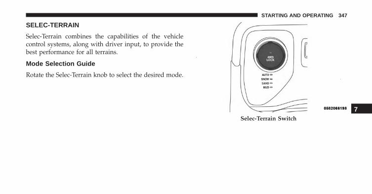
SELEC-TERRAIN
Selec-Terrain combines the capabilities of the vehiclecontrol systems, along with driver input, to provide thebest performance for all terrains.
Mode Selection Guide
Rotate the Selec-Terrain knob to select the desired mode.
Selec-Terrain Switch
7
STARTING AND OPERATING 347
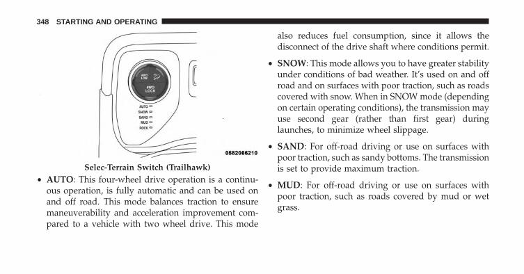
• AUTO: This four-wheel drive operation is a continu-ous operation, is fully automatic and can be used onand off road. This mode balances traction to ensuremaneuverability and acceleration improvement com-pared to a vehicle with two wheel drive. This mode
also reduces fuel consumption, since it allows thedisconnect of the drive shaft where conditions permit.
• SNOW: This mode allows you to have greater stabilityunder conditions of bad weather. It’s used on and offroad and on surfaces with poor traction, such as roadscovered with snow. When in SNOW mode (dependingon certain operating conditions), the transmission mayuse second gear (rather than first gear) duringlaunches, to minimize wheel slippage.
• SAND: For off-road driving or use on surfaces withpoor traction, such as sandy bottoms. The transmissionis set to provide maximum traction.
• MUD: For off-road driving or use on surfaces withpoor traction, such as roads covered by mud or wetgrass.
Selec-Terrain Switch (Trailhawk)
348 STARTING AND OPERATING

• ROCK (Trailhawk only): This mode is only availablein 4WD LOW range. The device sets the vehicle tomaximize traction and allow the highest steering ca-pacity for off-road surfaces. This mode gives you themaximum performance off-road. Use for low speedobstacles such as large rocks, deep ruts, etc.
NOTE:
• Rock mode is only available on the vehicles equippedwith the Off-Road package.
• Activate the Hill Descent Control or Selec SpeedControl for steep downhill control. Refer to “ElectronicBrake Control System” in “Safety” located in theOwner’s Manual on the DVD for further information.
FORWARD COLLISION WARNING (FCW) WITHMITIGATION — IF EQUIPPED
Forward Collision Warning (FCW) With MitigationOperation — If Equipped
The Forward Collision Warning (FCW) system withmitigation provides the driver with audible warnings,visual warnings (within the EVIC/DID), and may applya brake jerk to warn the driver when it detects a potentialfrontal collision. The warnings and limited braking areintended to provide the driver with enough time to react,avoid or mitigate the potential collision. 7
STARTING AND OPERATING 349

NOTE:
• FCW monitors the information from the forward look-ing sensors as well as the Electronic Brake Controller(EBC), to calculate the probability of a forward colli-sion. When the system determines that a forwardcollision is probable, the driver will be provided withaudible and visual warnings and may provide a brakejerk warning.
• If the driver does not take action based upon theseprogressive warnings, then the system will provide alimited level of active braking to help slow the vehicleand mitigate the potential forward collision. If thedriver reacts to the warnings by braking and thesystem determines that the driver intends to avoid thecollision by braking but has not applied sufficientbrake force, the system will compensate and provideadditional brake force as required.
Vehicles With A Manual Transmission: After the end ofthe intervention of automatic braking, the engine couldstall, unless the driver can depress the clutch pedal.
Vehicles With Automatic Transmission: After the end ofthe intervention of automatic braking, the transmissionmay remain in last gear stored: therefore the vehiclecould lurch forward, once the brakes release a fewseconds later. If the Forward Collision Warning withMitigation event stops the vehicle completely, the systemwill hold the vehicle at standstill for two seconds andthen release the brakes.
If a Forward Collision Warning with Mitigation eventbegins at a speed below 20 mph (32 km/h), the systemmay provide the maximum braking possible to mitigatethe potential forward collision. If the Forward CollisionWarning with Mitigation event stops the vehicle com-pletely, the system will hold the vehicle at standstill fortwo seconds and then release the brakes.
350 STARTING AND OPERATING

When the system determines a collision with the vehiclein front of you is no longer probable, the warningmessage will be deactivated.
NOTE:
• The minimum speed for FCW activation is 4 mph(7 km/h).
• The maximum speed for FCW activation is 124 mph(200 km/h).
• The FCW alerts may be triggered on objects other thanvehicles such as guard rails or sign posts based on thecourse prediction. This is expected and is a part ofnormal FCW activation and functionality.
• The FCW system is intended for on-road use only. Ifthe vehicle is taken off-road, the FCW system shouldbe deactivated to prevent unnecessary warnings to thesurroundings.
• If the vehicle enters 4WD Low Range, the FCW systemwill be automatically deactivated.
FCW Message7
STARTING AND OPERATING 351
• The active braking is enabled only if the front seat beltsare fastened.
• The active braking is disabled when a trailer is con-nected with a Mopar Trailer Towing system. If thevehicle is equipped with an aftermarket system, it isrecommended that the Active Braking is turned offmanually.
WARNING!
Forward Collision Warning (FCW) is not intended toavoid a collision on its own, nor can FCW detectevery type of potential collision. The driver has theresponsibility to avoid a collision by controlling thevehicle via braking and steering. Failure to followthis warning could lead to serious injury or death.
Turning FCW ON Or OFF
The forward collision menu setting is located in theUconnect settings.
NOTE: The default status of FCW is “Warning + ActiveBraking,” this allows the system to warn you of apossible collision with the vehicle in front of you andenable the active braking.
• Changing the FCW status to “Off” deactivates thesystem, so no warning or active braking will beavailable in case of a possible collision
• Changing the FCW status to “Only warning” preventsthe system from providing limited active braking, oradditional brake support if the driver is not brakingadequately in the event of a potential frontal collision,but maintains the audible and visual warnings.
352 STARTING AND OPERATING

Changing the status of the system is only possible withthe vehicle at a complete stop.
NOTE: The FCW system state is not kept in memoryfrom one key cycle to the next. If the system is turnedOFF, it will turn On when the vehicle is restarted.
Changing FCW Sensitivity
By changing the settings on the menu of the Uconnectsystem, you can change the sensitivity of the system bychoosing one of the following three options: �Near�,�Medium� or �Far�. Refer to “Uconnect Settings” in “Mul-timedia” for further information.
The default option is �Medium�. This setting providesthat the system notify the driver of a possible accidentwith the vehicle ahead of it when the latter is at astandard distance, intermediate between the other twopossible settings.
By setting the sensitivity of the system to �Far�, thesystem will warn the driver of a possible accident withthe vehicle in front when the latter is at a greater distance,giving you the chance to act on the brakes in a morelimited and gradual. This setting gives the driver themaximum possible time of reaction to prevent a possibleaccident.
By changing the option to �Near�, the system will warnthe driver of a possible accident with the vehicle ahead ofit when the latter is a reduced distance. This setting offersa reaction time to the driver lower than the settings�Medium� and �Far�, in the case of a potential accident,while a more dynamic driving of the vehicle.
The setting of the sensitivity of the system is maintainedin memory when the engine is switched off.
7
STARTING AND OPERATING 353

FCW Limited Warning
If the EVIC/DID displays “FCW Limited Functionality”or “FCW Limited Functionality Wipe Front Windshield”momentarily, there may be a condition that limits FCWfunctionality. Although the vehicle is still drivable undernormal conditions, the active braking may not be fullyavailable. Once the condition that limited the systemperformance is no longer present, the system will returnto its full performance state. If the problem persists, seeyour authorized dealer.
Service FCW Warning
If the system turns off, and the EVIC/DID displays:
• FCW Unavailable Service Required
This indicates there is an internal system fault. Althoughthe vehicle is still drivable under normal conditions, havethe system checked by an authorized dealer.
“Wipe Front Radar Sensor In Front Of Vehicle” Warn-ing
The “FCW Front Radar Sensor Temporarily Blocked”warning will display when conditions temporarily limitsystem performance. This most often occurs at times ofpoor visibility, such as in snow or heavy rain. The systemmay also become temporarily blinded due to obstruc-tions, such as mud, dirt or ice. In these cases, theEVIC/DID will display “FCW Front Radar Sensor Tem-porarily Blocked” and the system will deactivate.
The “FCW Front Radar Sensor Temporarily Blocked”message can sometimes be displayed while driving inhighly reflective areas (i.e. tunnels with reflective tiles, orice and snow). The system will recover after the vehiclehas left these areas. Under rare conditions, when theradar is not tracking any vehicles or objects in its paththis warning may temporarily occur.
354 STARTING AND OPERATING

If weather conditions are not a factor, the driver shouldexamine the sensor. It may require cleaning or removal ofan obstruction. The sensor is located behind the lowergrille. In absence of visible obstructions on the bumper, itcould be necessary to wipe off the radar directly on thesurface, after having the radar cover removed. It’s rec-ommended that your authorized dealer perform’s thisoperation.
NOTE:
• If the “FCW Front Radar Sensor Temporarily Blocked”message occurs frequently (e.g. more than once onevery trip) without any snow, rain, mud, or otherobstruction, have the radar sensor realigned at yourauthorized dealer.
• Installing a snow plow, front-end protector, an after-market grille or modifying the grille is not recom-mended. Doing so may block the sensor and inhibitFCW operation.
Precautions While Driving With FCW
In certain driving conditions, such as:
• Driving in the vicinity of a curve
• Small vehicles and/or not aligned to the lane
• Lane changing of other vehicles
• Passing of vehicles in an oncoming intersection
The intervention of the system could be unexpected ordelayed. The driver must therefore always pay particularattention, while maintaining control of the vehicle todrive in complete safety.
7
STARTING AND OPERATING 355
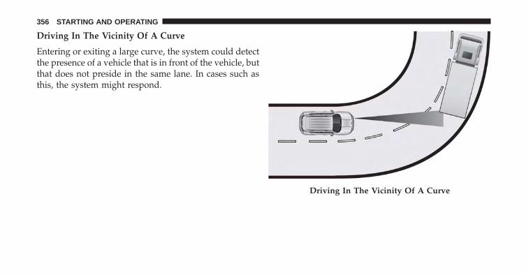
Driving In The Vicinity Of A Curve
Entering or exiting a large curve, the system could detectthe presence of a vehicle that is in front of the vehicle, butthat does not preside in the same lane. In cases such asthis, the system might respond.
Driving In The Vicinity Of A Curve
356 STARTING AND OPERATING

Small Vehicles And/Or Not Aligned To The Lane
The system is not able to detect the presence of vehicles thatare in front of the vehicle but placed outside the field ofaction of the radar sensor and could therefore not react in thepresence of small vehicles such as bicycles or motorcycles.
Lane Changing Of Other Vehicles
Vehicles that suddenly change lane, while standing in thetraffic lane of their vehicle and inside the field of action ofthe radar sensor may cause the intervention of the system.
Passing Of Vehicles In An Oncoming IntersectionSmall Vehicles And/Or Not Aligned To The LaneLane Changing Of Other Vehicles
7
STARTING AND OPERATING 357

The system could temporarily react to a vehicle thatcrossed the range of the radar sensor, in an oncomingintersection.
General Information
This vehicle has systems that operate on radio frequencythat comply with Part 15 of the Federal CommunicationsCommission (FCC) rules and with Industry CanadaStandards RSS- GEN/210/220/310.
Operation is subject to the following two conditions:
1. The device may not cause harmful interference.
2. The device must accept any interference received,including interference that may cause undesired op-eration of the device.
Changes or modifications to any of these systems byother than an authorized service facility could voidauthorization to use this equipment.
Passing Of Vehicles In An Oncoming Intersection
358 STARTING AND OPERATING

LANESENSE — IF EQUIPPED
LaneSense Operation
The LaneSense system is operational at speeds above37 mph (60 km/h) and below 112 mph (180 km/h). TheLaneSense system uses a forward looking camera todetect lane markings and measure vehicle positionwithin the lane boundaries.
When both lane markings are detected and the driverunintentionally drifts out of the lane (no turn signalapplied), the LaneSense system provides a haptic warn-ing in the form of torque applied to the steering wheel toprompt the driver to remain within the lane boundaries.If the driver continues to unintentionally drift out of thelane, the LaneSense system provides a visual warningthrough the Electronic Vehicle Information Center (EVIC)or Driver Information Display (DID) to prompt the driverto remain within the lane boundaries.
The driver may manually override the haptic warning byapplying torque into the steering wheel at any time.
When only a single lane marking is detected and thedriver unintentionally drifts across the lane marking (noturn signal applied), the LaneSense system provides avisual warning through the EVIC/DID to prompt thedriver to remain within the lane. When only a single lanemarking is detected, a haptic (torque) warning will not beprovided.
NOTE: When operating conditions have been met, theLaneSense system will monitor if the driver’s hands areon the steering wheel and provides an audible warningto the driver when the driver’s hands are not detected onthe steering wheel. The system will cancel if the driverdoes not return their hands to the wheel.
7
STARTING AND OPERATING 359

Turning LaneSense ON Or OFF
The default status of LaneSense is “OFF”.
The LaneSense button is located on the switch panelbelow the Uconnect display.
To turn the LaneSense system ON, push theLaneSense button (LED turns on). A “Lane Sense
On” message is shown in the EVIC/DID.
To turn the LaneSense system OFF, push the LaneSensebutton once (LED turns off).
NOTE: The LaneSense system will retain the last systemstate ON or OFF from the last ignition cycle when theignition is changed to the ON/RUN position.
LaneSense Warning Message
The LaneSense system will indicate the current lane driftcondition through the Electronic Vehicle InformationCenter (EVIC) or Driver Information Display (DID).
3.5 EVIC Screen — If Equipped
When the LaneSense system is ON, the lane lines are graywhen both of the lane boundaries have not been detectedand the LaneSense indicator is solid white.
System ON (Gray Lines/White Indicator)
360 STARTING AND OPERATING

Left Lane Departure — Only Left Lane Detected
• When the LaneSense system is ON, the LaneSenseindicator is solid white when only the left lane mark-ing has been detected and the system is ready toprovide visual warnings in the EVIC if an uninten-tional lane departure occurs.
• When the LaneSense system senses the lane has beenapproached and is in a lane departure situation, theleft thick lane line flashes from white to gray, the leftthin line remains solid white and the LaneSense indi-cator changes from solid white to flashing yellow.
NOTE: The LaneSense system operates with the similarbehavior for a right lane departure when only the rightlane marking has been detected.
Lane Approached (Flashing White To Gray ThickLine/Flashing Yellow Indicator)
7
STARTING AND OPERATING 361

Left Lane Departure — Both Lanes Detected
• When the LaneSense system is ON, the lane lines turnfrom gray to white to indicate that both of the lanemarkings have been detected. The LaneSense indicatoris solid green when both lane markings have beendetected and the system is “armed” to provide visualwarnings in the EVIC and a torque warning in thesteering wheel if an unintentional lane departure oc-curs.
• When the LaneSense system senses a lane drift situa-tion, the left thick lane line and the left thin line turnsolid white. The LaneSense indicator changes fromsolid green to solid yellow. At this time torque isapplied to the steering wheel in the opposite directionof the lane boundary.
Lanes Sensed (White Lines/Green Indicator)
362 STARTING AND OPERATING

• For example: If approaching the left side of the lane,the steering wheel will turn to the right.
• When the LaneSense system senses the lane has beenapproached and is in a lane departure situation, theleft thick lane line flashes from white to gray, the leftthin line remains solid white and the LaneSense indi-cator changes from solid yellow to flashing yellow. Atthis time, torque is applied to the steering wheel in theopposite direction of the lane boundary.
Lane Sensed (Solid White Thick Line, Solid White ThinLine/Solid Yellow Indicator)
7
STARTING AND OPERATING 363

• For example: If approaching the left side of the lane,the steering wheel will turn to the right.
NOTE: The LaneSense system operates with the similarbehavior for a right lane departure.
7.0 DID Screen — If Equipped
When the LaneSense system is ON, the lane lines are graywhen both of the lane boundaries have not been detectedand the LaneSense indicator is solid white.
Lane Approached (Flashing White To Gray Thick Line,Solid White Thin Line/Flashing Yellow Indicator)
System ON (Gray Lines/White Indicator)
364 STARTING AND OPERATING

Left Lane Departure — Only Left Lane Detected
• When the LaneSense system is ON, the LaneSenseindicator is solid white when only the left lane mark-ing has been detected and the system is ready toprovide visual warnings in the DID if an unintentionallane departure occurs.
• When the LaneSense system senses the lane has beenapproached and is in a lane departure situation, theleft thick lane line flashes yellow (on/off), the left thinline remains solid yellow and the LaneSense indicatorchanges from solid white to flashing yellow.
NOTE: The LaneSense system operates with the similarbehavior for a right lane departure when only the rightlane marking has been detected.
Lane Approached (Flashing Yellow Thick Line, SolidYellow Thin Line/Flashing Yellow Indicator)
7
STARTING AND OPERATING 365

Left Lane Departure — Both Lanes Detected
• When the LaneSense system is ON, the lane lines turnfrom gray to white to indicate that both of the lanemarkings have been detected. The LaneSense indicatoris solid green when both lane markings have beendetected and the system is “armed” to provide visualwarnings in the DID and a torque warning in thesteering wheel if an unintentional lane departure oc-curs.
• When the LaneSense system senses a lane drift situa-tion, the left thick lane line and left thin line turn solidyellow. The LaneSense indicator changes from solidgreen to solid yellow. At this time torque is applied tothe steering wheel in the opposite direction of the laneboundary.
Lanes Sensed (White Lines/Green Indicator)
366 STARTING AND OPERATING

• For example: If approaching the left side of the lanethe steering wheel will turn to the right.
• When the LaneSense system senses the lane has beenapproached and is in a lane departure situation, theleft thick lane line flashes yellow (on/off) and the leftthin line remains solid yellow. The LaneSense indicatorchanges from solid yellow to flashing yellow. At thistime torque is applied to the steering wheel in theopposite direction of the lane boundary.
Lane Sensed (Solid Yellow Thick Line, Solid YellowThin Line/Solid Yellow Indicator)
7
STARTING AND OPERATING 367

• For example: If approaching the left side of the lanethe steering wheel will turn to the right.
NOTE: The LaneSense system operates with the similarbehavior for a right lane departure.
Changing LaneSense Status
The LaneSense system has settings to adjust the intensityof the torque warning and the warning zone sensitivity(early/late) that you can configure through the Uconnectsystem screen. Refer to “Uconnect Settings” in “Multime-dia” for further information.
NOTE:
• When enabled the system operates above 37 mph(60 km/h) and below 112 mph (180 km/h).
• Use of the turn signal suppresses the warnings.
• The system will not apply torque to the steering wheelwhenever a safety system engages. (anti-lock brakes,traction control system, electronic stability control,forward collision warning, etc.).
Lane Approached (Flashing Yellow Thick Line, SolidYellow Thin Line/Flashing Yellow Indicator)
368 STARTING AND OPERATING

REAR PARKSENSE — IF EQUIPPED
The Rear ParkSense system provides visual and audibleindications of the distance between the rear fascia and adetected obstacle when backing up, e.g. during a parkingmaneuver. Refer to ParkSense System Usage Precautionsfor limitations of this system and recommendations.
Rear ParkSense will retain the last system state (enabledor disabled) from the last ignition cycle when the ignitionis changed to the MAR/RUN position.
Rear ParkSense can be active only when the gear selectoris in REVERSE.
Rear ParkSense Sensors
The four Rear ParkSense sensors, located in the rearfascia/bumper, monitor the area behind the vehicle thatis within the sensors’ field of view. The sensors can detectobstacles from approximately 12 inches (30 cm) up to 59inches (150 cm) from the rear fascia/bumper in the
horizontal direction, depending on the location, type andorientation of the obstacle.
Parking Sensors
7
STARTING AND OPERATING 369

Chime
By shifting the vehicle in REVERSE and in the case of thepresence of a rear obstacle, an acoustic signal that varieswith the distance of the obstacle from the bumper isactivated.
The frequency of the acoustic signal:
• Increases with the distance between vehicle and objectdecreases.
• Becomes continuous when the distance that separatesthe vehicle from the obstacle is less than approxi-mately 12 inches (30 cm), while terminates immedi-ately if the distance to the obstacle increases.
• Remains constant if the distance between vehicle andobstacle remains unchanged. If this situation occursfor the side sensors, the signal is stopped after approxi-mately three seconds to avoid, for example, it activatesin case of maneuver along a wall.
When the system emits a beeping sound, the volume ofthe Uconnect system, if turned on, is automaticallylowered by Rear ParkSense.
Detection Distances
If the sensors detect more obstacles, it is taken intoaccount only what is the shorter distance.
Instrument Cluster Display
Rear ParkSense is displayed on the instrument clusteronly if you have selected the item �beep and display�inside the �Settings� menu of the Uconnect system.
If an obstacle is detected in the center rear region, thedisplay will show a single solid arc in the center rearregion and will produce a one-half second tone. As thevehicle moves closer to the obstacle, the display willshow the single arc moving closer to the vehicle and thesound tone will change from slow, to fast, to continuous.
370 STARTING AND OPERATING

If an obstacle is detected in the left and/or right rearregion, the display will show a single flashing arc in theleft and/or right rear region and will produce a fastsound tone. As the vehicle moves closer to the obstacle,the display will show the single arc moving closer to thevehicle and the tone will change from fast to continuous.
In general, the vehicle is closest to the obstacle when thedisplay shows only a flashing arc and the chime becomescontinuous.
The color on the display depends on the distance andlocation of the obstacle.
Enabling And Disabling Rear ParkSense
Rear ParkSense can be enabled and disabled with theRear ParkSense switch.
When the Rear ParkSense switch is pushed todisable the system, the instrument cluster willdisplay the “PARKSENSE DISABLED” message
for approximately five seconds. Refer to “Electronic VehicleInformation Center (EVIC)” or “Driver Information Display(DID)” in “Getting To Know Your Instrument Cluster” forfurther information. When the gear selector is moved toREVERSE and the system is disabled, the EVIC/DID willdisplay the “PARKSENSE DISABLED” message for as longas the vehicle is in REVERSE.
The Rear ParkSense switch LED will be ON when RearParkSense is disabled or requires service. The RearParkSense switch LED will be OFF when the system isenabled. If the Rear ParkSense switch is pushed, andrequires service, the Rear ParkSense switch LED willblink momentarily, and then the LED will be ON.
Rear ParkSense will remember the previous state whenthe vehicle is switch off.
7
STARTING AND OPERATING 371

CAUTION!
After turning off the ignition, the Rear ParkSenseremains in this setting until the next key cycle, evenin the case of changing the setting of starting MAR/RUN to STOP/OFF and then again in MAR/RUN.
Service The Rear ParkSense System
During vehicle start up, when the Rear ParkSense Systemhas detected a faulted condition, the instrument clusterwill actuate a single chime, once per ignition cycle, and itwill display the “PARKSENSE UNAVAILABLE WIPEREAR SENSORS” or the “PARKSENSE UNAVAILABLESERVICE REQUIRED” message. Refer to “ElectronicVehicle Information Center (EVIC) or Driver InformationDisplay (DID)” for further information. When the gearselector is moved to REVERSE and the system hasdetected a faulted condition, the EVIC/DID will display
the �PARKSENSE UNAVAILABLE WIPE REAR SEN-SORS� or �PARKSENSE UNAVAILABLE SERVICE RE-QUIRED� message for as long as the vehicle is in RE-VERSE. Under this condition, Rear ParkSense will notoperate.
If “PARKSENSE UNAVAILABLE WIPE REAR SEN-SORS” appears in the Electronic Vehicle InformationCenter (EVIC) or Driver Information Display (DID) makesure the outer surface and the underside of the rearfascia/bumper is clean and clear of snow, ice, mud, dirtor other obstructions and then cycle the ignition. If themessage continues to appear, see an authorized dealer.
If “PARKSENSE UNAVAILABLE SERVICE REQUIRED”appears in the EVIC/DID, see an authorized dealer.
372 STARTING AND OPERATING

ParkSense System Usage Precautions
NOTE:
• Ensure that the outer surface and the underside of therear bumper is clean and clear of snow, ice, mud, dirtor other obstruction to keep the Rear ParkSense systemoperating properly.
• Jackhammers, large trucks, and other vibrations couldaffect the performance of Rear ParkSense.
• Clean the Rear ParkSense sensors regularly, takingcare not to scratch or damage them. The sensors mustnot be covered with ice, snow, slush, mud, dirt ordebris. Failure to do so can result in the system notworking properly. The Rear ParkSense system mightnot detect an obstacle behind the fascia/bumper, or itcould provide a false indication that an obstacle isbehind the fascia/bumper.
• Objects such as bicycle carriers, etc., must not beplaced within 12 inches (30 cm) from the rear fascia/bumper while driving the vehicle. Failure to do so canresult in the system misinterpreting a close object as asensor problem, causing a failure indication to bedisplayed in the instrument cluster.
WARNING!
• Drivers must be careful when backing up evenwhen using ParkSense. Always check carefullybehind your vehicle, look behind you, and be sureto check for pedestrians, animals, other vehicles,obstructions, and blind spots before backing up.You are responsible for safety and must continue topay attention to your surroundings. Failure to do socan result in serious injury or death.
(Continued)
7
STARTING AND OPERATING 373

WARNING! (Continued)• Before using ParkSense, it is strongly recom-
mended that the ball mount and hitch ball assem-bly is disconnected from the vehicle when thevehicle is not used for towing. Failure to do so canresult in injury or damage to vehicles or obstaclesbecause the hitch ball will be much closer to theobstacle than the rear fascia when the loudspeakersounds the continuous tone. Also, the sensorscould detect the ball mount and hitch ball assem-bly, depending on its size and shape, giving a falseindication that an obstacle is behind the vehicle.
CAUTION!
• ParkSense is only a parking aid and it is unable torecognize every obstacle, including small obstacles.
(Continued)
CAUTION! (Continued)Parking curbs might be temporarily detected or notdetected at all. Obstacles located above or belowthe sensors will not be detected when they are inclose proximity.
• The vehicle must be driven slowly when usingParkSense in order to be able to stop in time whenan obstacle is detected. It is recommended that thedriver looks over his/her shoulder when usingParkSense.
If it’s necessary to keep the trailer hitch and hitch ballassembly mounted for a long period, it is possible to filterout the trailer hitch and hitch ball assembly presence insensor field of view. The filtering operation must beperformed only by an authorized dealer.
374 STARTING AND OPERATING

REAR BACK UP CAMERA — IF EQUIPPED
The Rear Back Up Camera that allows you to see anon-screen image of your vehicle’s rear surroundingswhen the gear selector is put into REVERSE. The imagewill be displayed on the touchscreen display along witha note to “check entire surroundings” across the top ofthe screen. After five seconds this note will disappear.The camera is located above the rear license plate.
When the vehicle is shifted out of REVERSE (with cameradelay turned OFF), the rear camera mode is exited andthe navigation or audio screen appears again.
Parking Camera7
STARTING AND OPERATING 375

When the vehicle is shifted out of REVERSE (with cameradelay turned ON), the camera image will continue to bedisplayed for up to 10 seconds after shifting out ofREVERSE unless the vehicle speed exceeds 8 mph(13 km/h), the vehicle is shifted into PARK or the ignitionis switched to the STOP/OFF position.
A touchscreen button to disable the camera is availablewhen the vehicle is not in REVERSE or if touchscreenbutton “X” at the top of the camera screen is pressed.Display of the camera image after shifting out of RE-VERSE can be disabled via Uconnect Settings.
When enabled, active guide lines are overlaid on the imageto illustrate the width of the vehicle and its projectedbackup path based on the steering wheel position.
When enabled, fixed guide lines are overlaid on theimage to illustrate the width of the vehicle.
Different colored zones indicate the distance to the rear ofthe vehicle.
The following table shows the approximate distances foreach zone:
Zone Distance to the rear of the vehicleRed 0 - 1 ft (0 - 30 cm)
Yellow 1 ft - 3 ft (30 cm - 1 m)Green 3 ft or greater (1 m or greater)
376 STARTING AND OPERATING

NOTE: If snow, ice, mud, or any foreign substance buildsup on the camera lens, clean the lens, rinse with water,and dry with a soft cloth. Do not cover the lens.
WARNING!
Drivers must be careful when backing up even whenusing the Rear Back Up Camera. Always check care-fully behind your vehicle, and be sure to check forpedestrians, animals, other vehicles, obstructions, orblind spots before backing up. You are responsiblefor the safety of your surroundings and must con-tinue to pay attention while backing up. Failure to doso can result in serious injury or death.
CAUTION!
• To avoid vehicle damage, Rear Back Up Camerashould only be used as a parking aid. The RearBack Up Camera is unable to view every obstacle orobject in your drive path.
• To avoid vehicle damage, the vehicle must bedriven slowly when using the Rear Back Up Cam-era to be able to stop in time when an obstacle isseen. It is recommended that the driver look fre-quently over his/her shoulder when using the RearBack Up Camera. 7
STARTING AND OPERATING 377

TIRE PRESSURE MONITOR SYSTEM (TPMS)
The Tire Pressure Monitor System (TPMS) will warn thedriver of a low tire pressure based on the vehicle recom-mended cold placard pressure.
The tire pressure will vary with temperature by approxi-mately 1 psi (7 kPa) for every 12°F (6.5°C). This meansthat when the outside temperature decreases, the tirepressure will decrease. Tire pressure should always be setbased on cold inflation tire pressure. This is defined asthe tire pressure after the vehicle has not been driven forat least three hours, or driven less than 1 mile (1.6 km)after a three hour period. The cold tire inflation pressuremust not exceed the maximum inflation pressure moldedinto the tire sidewall. Refer to “Tires – General Informa-tion” in “Maintaining And Caring For Your Vehicle” forinformation on how to properly inflate the vehicle’s tires.
The tire pressure will also increase as the vehicle isdriven. This is normal and there should be no adjustmentfor this increased pressure.
The TPMS will warn the driver of a low tire pressure ifthe tire pressure falls below the low-pressure warninglimit for any reason, including low temperature effectsand natural pressure loss through the tire.
The TPMS will continue to warn the driver of low tirepressure as long as the condition exists, and will not turnoff until the tire pressure is at or above the recommendedcold placard pressure. Once the low tire pressure warn-ing (Tire Pressure Monitoring Telltale Light) illuminates,you must increase the tire pressure to the recommendedcold placard pressure in order for the “Tire PressureMonitoring Telltale Light” to turn off.
378 STARTING AND OPERATING

NOTE: When filling warm tires, the tire pressure mayneed to be increased up to an additional 4 psi (30 kPa)above the recommended cold placard pressure in orderto turn the Tire Pressure Monitoring Telltale Light off.
The system will automatically update and the “TirePressure Monitoring Telltale Light” will turn off once thesystem receives the updated tire pressures. The vehiclemay need to be driven for up to 20 minutes above15.5 mph (25 km/h) in order for the TPMS to receive thisinformation.
For example, your vehicle may have a recommendedcold (parked for more than three hours) placard pressureof 33 psi (227 kPa). If the ambient temperature is 68°F(20°C) and the measured tire pressure is 28 psi (193 kPa),a temperature drop to 20°F (-7°C) will decrease the tirepressure to approximately 24 psi (165 kPa). This tirepressure is low enough to turn ON the “Tire PressureMonitoring Telltale Light.” Driving the vehicle may cause
the tire pressure to rise to approximately 28 psi (193 kPa),but the “Tire Pressure Monitoring Telltale Light” will stillbe on. In this situation, the “Tire Pressure MonitoringTelltale Light” will turn off only after the tires are inflatedto the vehicle’s recommended cold placard pressurevalue.
NOTE: When filling warm tires, the tire pressure mayneed to be increased up to an additional 4 psi (30 kPa)above the recommended cold placard pressure in orderto turn the Tire Pressure Monitoring Telltale Light off.
CAUTION!
• The TPMS has been optimized for the originalequipment tires and wheels. TPMS pressures andwarning have been established for the tire sizeequipped on your vehicle. Undesirable system op-eration or sensor damage may result when using
(Continued)
7
STARTING AND OPERATING 379

CAUTION! (Continued)replacement equipment that is not of the same size,type, and/or style. Aftermarket wheels can causesensor damage.
• Using aftermarket tire sealants may cause the TirePressure Monitoring System (TPMS) sensor to be-come inoperable. After using an aftermarket tiresealant it is recommended that you take yourvehicle to an authorized dealership to have yoursensor function checked.
• After inspecting or adjusting the tire pressure al-ways reinstall the valve stem cap. This will preventmoisture and dirt from entering the valve stem,which could damage the TPMS sensor.
NOTE:
• The TPMS is not intended to replace normal tire careand maintenance, or to provide warning of a tirefailure or condition.
• The TPMS should not be used as a tire pressure gaugewhile adjusting your tire pressure.
• Driving on a significantly underinflated tire causes thetire to overheat and can lead to tire failure. Underin-flation also reduces fuel efficiency and tire tread life,and may affect the vehicle’s handling and stoppingability.
• The TPMS is not a substitute for proper tire mainte-nance, and it is the driver’s responsibility to maintaincorrect tire pressure using an accurate tire pressuregauge, even if underinflation has not reached the levelto trigger illumination of the “Tire Pressure Monitor-ing Telltale Light”.
380 STARTING AND OPERATING

• Seasonal temperature changes will affect tire pressure,and the TPMS will monitor the actual tire pressure inthe tire.
Base System
The Tire Pressure Monitor System (TPMS) uses wirelesstechnology with wheel rim mounted electronic sensors tomonitor tire pressure levels. Sensors, mounted to eachwheel as part of the valve stem, transmit tire pressurereadings to the receiver module.
NOTE: It is particularly important for you to check thetire pressure in all of the tires on your vehicle monthlyand to maintain the proper pressure.
The TPMS consists of the following components:
• Receiver Module
• Four Tire Pressure Monitoring Sensors
• Tire Pressure Monitoring Telltale Light
Tire Pressure Monitoring Low Pressure Warnings
The “Tire Pressure Monitoring Telltale Light” willilluminate in the instrument cluster, a “LOW TIRE
PRESSURE” message will display in the instrumentcluster, an �Inflate to XX� message will be displayed anda chime will sound when tire pressure is low in one ormore of the four active road tires. Should this occur, youshould stop as soon as possible, check the inflationpressure of each tire on your vehicle, and inflate each tireto the vehicle’s recommended cold placard pressurevalue as shown in the �Inflate to XX� message. Once thesystem receives the updated tire pressures, the systemwill automatically update and the “Tire Pressure Moni-toring Telltale Light” will turn off.
7
STARTING AND OPERATING 381

NOTE: When filling warm tires, the tire pressure mayneed to be increased up to an additional 4 psi (30 kPa)above the recommended cold placard pressure in orderto turn the Tire Pressure Monitoring Telltale Light off.The vehicle may need to be driven for up to 20 minutesabove 15 mph (24 km/h) in order for the TPMS to receivethis information.
Service TPMS Warning
When a system fault is detected, the “Tire PressureMonitoring Telltale Light” will flash on and off for 75seconds and then remain on solid. The system fault willalso sound a chime. If the ignition is cycled, this sequencewill repeat, providing the system fault still exists. The“Tire Pressure Monitoring Telltale Light” will turn offwhen the fault condition no longer exists. A system faultcan occur due to any of the following:
1. Jamming due to electronic devices or driving next tofacilities emitting the same radio frequencies as theTPMS sensors.
2. Installing some form of aftermarket window tintingthat affects radio wave signals.
3. Lots of snow or ice around the wheels or wheelhousings.
4. Using tire chains on the vehicle.
5. Using wheels/tires not equipped with TPMS sensors.
Vehicles With Compact Spare or non-Matching FullSize Spare
1. The compact spare tire or non-matching full size sparetire does not have a tire pressure monitoring sensor.Therefore, the TPMS will not monitor the pressure inthe spare tire.
382 STARTING AND OPERATING
2. If you install the compact or non-matching full sizespare tire in place of a road tire that has a pressurebelow the low-pressure warning limit, a chime willsound and the “TPMS Telltale Light” and “LOW TIREPRESSURE” and �Inflate to XX� messages will turn onupon the next ignition cycle.
3. After driving the vehicle for up to 20 minutes above15 mph (24 km/h), the “TPMS Telltale Light” willflash on and off for 75 seconds and then remain onsolid.
4. For each subsequent ignition cycle, a chime will soundand the “TPMS Telltale Light” will flash on and off for75 seconds and then remain on solid.
5. Once you repair or replace the original road tire andreinstall it on the vehicle in place of the compact spareor non-matching full size spare, the TPMS will updateautomatically and the “TPMS Telltale Light” will turn
off, as long as no tire pressure is below the low-pressure warning limit in any of the four active roadtires. The vehicle may need to be driven for up to 20minutes above 15 mph (24 km/h) in order for theTPMS to receive this information.
Premium System — If Equipped
The Tire Pressure Monitor System (TPMS) uses wirelesstechnology with wheel rim mounted electronic sensors tomonitor tire pressure levels. Sensors, mounted to eachwheel as part of the valve stem, transmit tire pressurereadings to the receiver module.
NOTE: It is particularly important for you to check thetire pressure in all of the tires on your vehicle monthlyand to maintain the proper pressure.
The TPMS consists of the following components:
• Receiver Module
• Four Tire Pressure Monitoring Sensors
7
STARTING AND OPERATING 383

• Various Tire Pressure Monitoring System messages,which display in the Electronic Vehicle InformationCenter (EVIC) or Driver Information Display (DID).
• Tire Pressure Monitoring Telltale Light
Tire Pressure Monitoring Low Pressure Warnings
The “Tire Pressure Monitoring Telltale Light” willilluminate in the instrument cluster and a chime
will sound when tire pressure is low in one or more of thefour active road tires. In addition, the Electronic VehicleInformation Center (EVIC)/Driver information Display(DID) will display a �Tire Low� message for a minimumof five seconds, an �Inflate to XX� message and a graphicshowing the pressure values of each tire with the low tirepressure values in a different color.
Should this occur, you should stop as soon as possibleand inflate the tires with low pressure (those in adifferent color in the EVIC/DID graphic) to the vehicle’srecommended cold placard pressure value as shown inthe �Inflate to XX� message. Once the system receives theupdated tire pressures, the system will automatically
Tire Pressure Monitoring Low Pressure Warning
384 STARTING AND OPERATING

update, the pressure values in the graphic display in theEVIC/DID will return to their original color, and the“Tire Pressure Monitoring Telltale Light” will turn off.
NOTE: When filling warm tires, the tire pressure mayneed to be increased up to an additional 4 psi (30 kPa)above the recommended cold placard pressure in orderto turn the Tire Pressure Monitoring Telltale Light off.The vehicle may need to be driven for up to 20 minutesabove 15.5 mph (25 km/h) in order for the TPMS toreceive this information.
SERVICE TPMS Warning
When a system fault is detected, the “Tire PressureMonitoring Telltale Light” will flash on and off for 75seconds and then remain on solid. The system fault willalso sound a chime. In addition, the EVIC/DID will
display a �SERVICE TPM SYSTEM� message for a mini-mum of five seconds and then display dashes (- -) inplace of the pressure value to indicate which sensor is notbeing received.
If the ignition key is cycled, this sequence will repeat,providing the system fault still exists. If the system faultno longer exists, the “Tire Pressure Monitoring TelltaleLight” will no longer flash, and the “SERVICE TPMSYSTEM” message will no longer display, and a pressurevalue will display in place of the dashes. A system faultcan occur due to any of the following:
1. Jamming due to electronic devices or driving next tofacilities emitting the same radio frequencies as theTPMS sensors.
2. Installing some form of aftermarket window tintingthat affects radio wave signals.
7
STARTING AND OPERATING 385

3. Lots of snow or ice around the wheels or wheelhousings.
4. Using tire chains on the vehicle.
5. Using wheels/tires not equipped with TPMS sensors.
Vehicles With Matching Full-Size Spare
1. The matching full size spare wheel and tire assemblyhas a tire pressure monitoring sensor that can bemonitored by the TPMS.
2. If you install the full size spare in place of a road tirethat has a pressure below the low-pressure warninglimit, a chime will sound and the “TPMS TelltaleLight” will turn on upon the next ignition key cycle. Inaddition, the EVIC/DID will display a Tire Lowmessage, an �Inflate to XX� message and a graphicshowing the low tire pressure value in a differentcolor.
3. After driving the vehicle for up to 20 minutes above15.5 mph (25 km/h) the “TPMS Telltale Light” willturn OFF, as long as no tire pressure is below thelow-pressure warning limit in any of the four activeroad tires.
4. The EVIC/DID will display a graphic showing the tirepressure value in the same color as the other pressurevalues in place of the different color low tire pressurevalue. The EVIC/DID will also display a “SPARELOW PRESSURE” message to remind you to servicethe flat tire.
Vehicles With Compact Spare or Non-Matching FullSize Spare
1. The compact spare tire or non-matching full size doesnot have a tire pressure monitoring sensor. Therefore,the TPMS will not monitor the pressure in the compactspare tire.
386 STARTING AND OPERATING

2. If you install the compact or non-matching full sizespare tire in place of a road tire that has a pressurebelow the low-pressure warning limit, upon the nextignition key cycle, the “TPMS Telltale Light” willremain on and a chime will sound. In addition, thegraphic in the EVIC/DID will still display a differentcolor pressure value and an �Inflate to XX� message.
3. After driving the vehicle for up to 20 minutes above15.5 mph (25 km/h), the “TPMS Telltale Light” willflash on and off for 75 seconds and then remain onsolid. In addition, the EVIC/DID will display a “SER-VICE TPM SYSTEM” message for five seconds andthen display dashes (- -) in place of the pressure value.
4. For each subsequent ignition key cycle, a chime willsound, the “TPMS Telltale Light” will flash on and offfor 75 seconds and then remain on solid, and the
EVIC/DID will display a “SERVICE TPM SYSTEM”message for five seconds and then display dashes (- -)in place of the pressure value.
5. Once you repair or replace the original road tire andreinstall it on the vehicle in place of the compact spareor non-matching full size, the TPMS will updateautomatically. In addition, the “TPMS Telltale Light”will turn off and the graphic in the EVIC/DID willdisplay a new pressure value instead of dashes (- -), aslong as no tire pressure is below the low-pressurewarning limit in any of the four active road tires. Thevehicle may need to be driven for up to 20 minutesabove 15.5 mph (25 km/h) in order for the TPMS toreceive this information.
7
STARTING AND OPERATING 387

General Information
This device complies with Part 15 of the FCC rules andRSS-210 of Industry Canada. Operation is subject to thefollowing two conditions:
(1) This device may not cause harmful interference.
(2) This device must accept any interference received,including interference that may cause undesired opera-tion.
NOTE: Changes or modifications not expressly approvedby the party responsible for compliance could void theuser’s authority to operate the equipment.
FUEL REQUIREMENTS
1.4L Turbo Engine
This engine is designed to meet allemission regulations and provide sat-isfactory fuel economy and perfor-mance when using high-quality un-leaded �regular� gasoline having anoctane rating of 87 using the (R+M)/2method. For optimum performance
and fuel economy the use of 91 octane or higher isrecommended.
While operating on gasoline with an octane number of87, hearing a light knocking sound from the engine is nota cause for concern. However, if the engine is heardmaking a heavy knocking sound, see your dealer imme-diately. Use of gasoline with an octane number lowerthan 87 can cause engine failure and may void or not becovered by the New Vehicle Limited Warranty.
388 STARTING AND OPERATING

Poor quality gasoline can cause problems such as hardstarting, stalling, and hesitations. If you experience thesesymptoms, try another brand of gasoline before consid-ering service for the vehicle.
2.4L Engine
All available gasoline engines are de-signed to meet all emissions regula-tions and provide excellent fueleconomy and performance when us-ing high quality unleaded “regular”gasoline having a octane rating of 87using the (R+M)/2 method. The use of
premium gasoline is not recommended, as it will notprovide any benefit over regular gasoline in these en-gines.
While operating on gasoline with an octane number of87, hearing a light knocking sound from the engine is nota cause for concern. However, if the engine is heard
making a heavy knocking sound, see your dealer imme-diately. Use of gasoline with an octane number lowerthan 87 can cause engine failure and may void or not becovered by the New Vehicle Limited Warranty.
Poor quality gasoline can cause problems such as hardstarting, stalling, and hesitations. If you experience thesesymptoms, try another brand of gasoline before consid-ering service for the vehicle.
Reformulated Gasoline
Many areas of the country require the use of cleanerburning gasoline referred to as “Reformulated Gasoline”.Reformulated gasoline contains oxygenates and are spe-cifically blended to reduce vehicle emissions and im-prove air quality.
The use of reformulated gasoline is recommended. Prop-erly blended reformulated gasoline will provide im-proved performance and durability of engine and fuelsystem components.
7
STARTING AND OPERATING 389

Gasoline/Oxygenate Blends
Some fuel suppliers blend unleaded gasoline with oxy-genates such as ethanol.
CAUTION!
DO NOT use gasoline containing methanol or gaso-line containing more than 15% ethanol (E-15). Use ofthese blends may result in starting and drivabilityproblems, damage critical fuel system components,cause emissions to exceed the applicable standard,and/or cause the “Malfunction Indicator Light” toilluminate. Please observe pump labels as theyshould clearly communicate if a fuel contains greaterthan 15% ethanol (E-15).
Problems that result from using gasoline containing morethan 15% ethanol (E-15) or gasoline containing methanol arenot the responsibility of the manufacturer and may void ornot be covered under New Vehicle Limited Warranty.
Modifications that allow the engine to run on com-pressed natural gas (CNG) or liquid propane (LP) mayresult in damage to the engine, emissions, and fuelsystem components. Problems that result from runningCNG or LP are not the responsibility of the manufacturerand many void or not be covered under the New VehicleLimited Warranty.
E-85 Usage In Non-Flex Fuel Vehicles
Non-Flex Fuel Vehicles (FFV) are compatible with gaso-line containing up to 15% ethanol (E-15). Gasoline withhigher ethanol content may void the New Vehicle Lim-ited Warranty.
If a Non-FFV vehicle is inadvertently fueled with E-85fuel, the engine will have some or all of these symptoms:
• Operate in a lean mode.
• OBD II “Malfunction Indicator Light” on.
• Poor engine performance.
390 STARTING AND OPERATING

• Poor cold start and cold drivability.
• Increased risk for fuel system component corrosion.
MMT In Gasoline
Methylcyclopentadienyl Manganese Tricarbonyl (MMT)is a manganese-containing metallic additive that isblended into some gasoline to increase octane. Gasolineblended with MMT provides no performance advantagebeyond gasoline of the same octane number withoutMMT. Gasoline blended with MMT reduces spark pluglife and reduces emissions system performance in somevehicles. The manufacturer recommends that gasolinewithout MMT be used in your vehicle. The MMT contentof gasoline may not be indicated on the gasoline pump,therefore, you should ask your gasoline retailer whetherthe gasoline contains MMT. MMT is prohibited in Federaland California reformulated gasoline.
Materials Added To Fuel
Besides using unleaded gasoline with the proper octanerating, gasolines that contain detergents, corrosion andstability additives are recommended. Using gasolines thathave these additives will help improve fuel economy,reduce emissions, and maintain vehicle performance.
Designated TOP TIER Detergent Gaso-line contains a higher level of deter-gents to further aide in minimizingengine and fuel system deposits.When available, the usage of Top TierDetergent gasoline is recommended.Visit www.toptiergas.com for a list of
TOP TIER Detergent Gasoline Retailers.
Indiscriminate use of fuel system cleaning agents shouldbe avoided. Many of these materials intended for gumand varnish removal may contain active solvents orsimilar ingredients. These can harm fuel system gasketand diaphragm materials.
7
STARTING AND OPERATING 391

Fuel System Cautions
CAUTION!
Follow these guidelines to maintain your vehicle’sperformance:• The use of leaded gasoline is prohibited by Federal
law. Using leaded gasoline can impair engine per-formance and damage the emissions control sys-tem.
• An out-of-tune engine or certain fuel or ignitionmalfunctions can cause the catalytic converter tooverheat. If you notice a pungent burning odor orsome light smoke, your engine may be out of tuneor malfunctioning and may require immediate ser-vice. Contact your authorized dealer for serviceassistance.
(Continued)
CAUTION! (Continued)• The use of fuel additives, which are now being
sold as octane enhancers, is not recommended.Most of these products contain high concentrationsof methanol. Fuel system damage or vehicle perfor-mance problems resulting from the use of suchfuels or additives is not the responsibility of themanufacturer and may void or not be coveredunder the New Vehicle Limited Warranty.
NOTE: Intentional tampering with the emissions controlsystem can result in civil penalties being assessed againstyou.
392 STARTING AND OPERATING

Carbon Monoxide Warnings
WARNING!
Carbon monoxide (CO) in exhaust gases is deadly.Follow the precautions below to prevent carbonmonoxide poisoning:• Do not inhale exhaust gases. They contain carbon
monoxide, a colorless and odorless gas, which cankill. Never run the engine in a closed area, such asa garage, and never sit in a parked vehicle with theengine running for an extended period. If thevehicle is stopped in an open area with the enginerunning for more than a short period, adjust theventilation system to force fresh, outside air intothe vehicle.
(Continued)
WARNING! (Continued)• Guard against carbon monoxide with proper main-
tenance. Have the exhaust system inspected everytime the vehicle is raised. Have any abnormalconditions repaired promptly. Until repaired, drivewith all side windows fully open.
ADDING FUEL
The Capless Fuel System uses a flapper placed at the fillerpipe of the fuel tank; it opens and closes automaticallyupon insertion/extraction of the fuel nozzle.
The Capless Fuel System is designed so that it preventsthe filling of an incorrect type of fuel.
7
STARTING AND OPERATING 393

Opening The Door
For filling proceed as follows:
• Open the door, by pushing and releasing on theindentation point indicated by the arrow.
• Insert the fuel nozzle in the filler pipe and proceedwith filling the fuel tank.
• Before removing the nozzle, wait at least 10 seconds toallow the fuel to flow inside of the tank.
• Pull the nozzle from the filler pipe and then close thedoor.
Fuel Filler Door
Filling Procedure
394 STARTING AND OPERATING

Emergency Refueling Procedure
If the vehicle is out of fuel proceed as follows:
• Open the liftgate and remove the emergency fuel fillfunnel located in the cargo area.
• Open the fuel door.
Emergency Fuel Fill Funnel
Emergency Fuel Fill Funnel – If Equipped with Full SizeSpare Tire
7
STARTING AND OPERATING 395
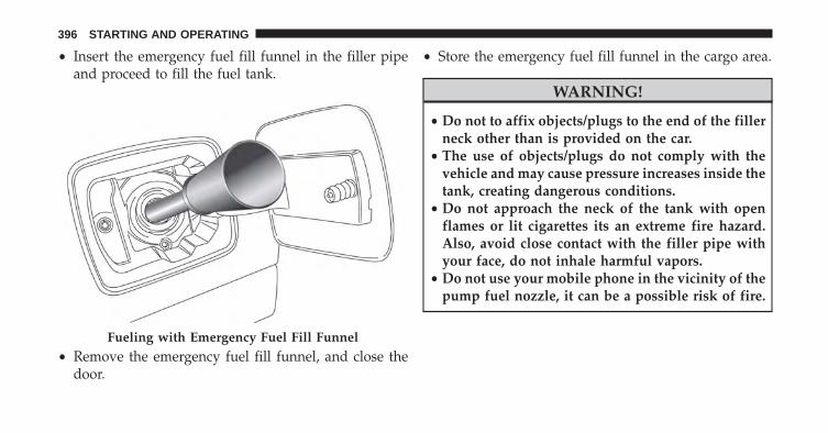
• Insert the emergency fuel fill funnel in the filler pipeand proceed to fill the fuel tank.
• Remove the emergency fuel fill funnel, and close thedoor.
• Store the emergency fuel fill funnel in the cargo area.
WARNING!
• Do not to affix objects/plugs to the end of the fillerneck other than is provided on the car.
• The use of objects/plugs do not comply with thevehicle and may cause pressure increases inside thetank, creating dangerous conditions.
• Do not approach the neck of the tank with openflames or lit cigarettes its an extreme fire hazard.Also, avoid close contact with the filler pipe withyour face, do not inhale harmful vapors.
• Do not use your mobile phone in the vicinity of thepump fuel nozzle, it can be a possible risk of fire.
Fueling with Emergency Fuel Fill Funnel
396 STARTING AND OPERATING

VEHICLE LOADING
Certification Label
As required by National Highway Traffic Safety Admin-istration regulations, your vehicle has a certification labelaffixed to the driver’s side door or pillar.
This label contains the month and year of manufacture,Gross Vehicle Weight Rating (GVWR), Gross Axle WeightRating (GAWR) front and rear, and Vehicle IdentificationNumber (VIN). A Month-Day-Hour (MDH) number isincluded on this label and indicates the Month, Day andHour of manufacture. The bar code that appears on thebottom of the label is your VIN.
Gross Vehicle Weight Rating (GVWR)
The GVWR is the total permissible weight of your vehicleincluding driver, passengers, vehicle, options and cargo.The label also specifies maximum capacities of front and
rear axle systems (GAWR). Total load must be limited soGVWR and front and rear GAWR are not exceeded.
Payload
The payload of a vehicle is defined as the allowable loadweight a truck can carry, including the weight of thedriver, all passengers, options and cargo.
Gross Axle Weight Rating (GAWR)
The GAWR is the maximum permissible load on the frontand rear axles. The load must be distributed in the cargoarea so that the GAWR of each axle is not exceeded.
Each axle GAWR is determined by the components in thesystem with the lowest load carrying capacity (axle,springs, tires or wheels). Heavier axles or suspensioncomponents sometimes specified by purchasers for in-creased durability does not necessarily increase the vehi-cle’s GVWR.
7
STARTING AND OPERATING 397

Tire Size
The tire size on the Vehicle Certification Label representsthe actual tire size on your vehicle. Replacement tiresmust be equal to the load capacity of this tire size.
Rim Size
This is the rim size that is appropriate for the tire sizelisted.
Inflation Pressure
This is the cold tire inflation pressure for your vehicle forall loading conditions up to full GAWR.
Curb Weight
The curb weight of a vehicle is defined as the total weightof the vehicle with all fluids, including vehicle fuel, at fullcapacity conditions, and with no occupants or cargoloaded into the vehicle. The front and rear curb weight
values are determined by weighing your vehicle on acommercial scale before any occupants or cargo areadded.
Loading
The actual total weight and the weight of the front andrear of your vehicle at the ground can best be determinedby weighing it when it is loaded and ready for operation.
The entire vehicle should first be weighed on a commer-cial scale to insure that the GVWR has not been exceeded.The weight on the front and rear of the vehicle shouldthen be determined separately to be sure that the load isproperly distributed over the front and rear axle. Weigh-ing the vehicle may show that the GAWR of either thefront or rear axles has been exceeded but the total load iswithin the specified GVWR. If so, weight must be shiftedfrom front to rear or rear to front as appropriate until thespecified weight limitations are met. Store the heavier
398 STARTING AND OPERATING

items down low and be sure that the weight is distributedequally. Stow all loose items securely before driving.
Improper weight distributions can have an adverse effecton the way your vehicle steers and handles and the waythe brakes operate.
CAUTION!
Do not load your vehicle any heavier than the GVWRor the maximum front and rear GAWR. If you do,parts on your vehicle can break, or it can change theway your vehicle handles. This could cause you tolose control. Also overloading can shorten the life ofyour vehicle.
ON-ROAD DRIVING TIPS
Utility vehicles have higher ground clearance and anarrower track to make them capable of performing in awide variety of off-road applications. Specific designcharacteristics give them a higher center of gravity thanordinary vehicles.
An advantage of the higher ground clearance is a betterview of the road, allowing you to anticipate problems.They are not designed for cornering at the same speeds asconventional two-wheel drive vehicles any more thanlow-slung sports cars are designed to perform satisfacto-rily in off-road conditions. If at all possible, avoid sharpturns or abrupt maneuvers. As with other vehicles of thistype, failure to operate this vehicle correctly may result inloss of control or vehicle rollover.
7
STARTING AND OPERATING 399

OFF-ROAD DRIVING TIPS
When To Use 4WD LOW Range
When off-road driving, shift to 4WD LOW for additionaltraction and control on slippery or difficult terrain,ascending or descending steep hills, and to increaselow-speed pulling power (refer to “All Wheel Drive andFour-Wheel Drive Operation” in this section for furtherdetails). This range should be limited to extreme situa-tions such as deep snow, mud, or sand where additionallow speed pulling power is needed. Vehicle speeds inexcess of 25 mph (40 km/h) should be avoided when in4WD LOW range.
Driving Through Water
Although your vehicle is capable of driving throughwater, there are a number of precautions that must beconsidered before entering the water:
CAUTION!
When driving through water, do not exceed 5 mph(8 km/h). Always check water depth before enteringas a precaution, and check all fluids afterward. Driv-ing through water may cause damage that may not becovered by the New Vehicle Limited Warranty.
Driving through water more than a few inches/centimeters deep will require extra caution to ensuresafety and prevent damage to your vehicle. If you mustdrive through water, try to determine the depth and thebottom condition (and location of any obstacles) prior toentering. Proceed with caution and maintain a steadycontrolled speed less than 5 mph (8 km/h) in deep waterto minimize wave effects.
400 STARTING AND OPERATING

Flowing Water
If the water is swift flowing and rising (as in storm run-off)avoid crossing until the water level recedes and/or the flowrate is reduced. If you must cross flowing-water, avoiddepths in excess of 9 inches (22 cm). The flowing water canerode the streambed causing your vehicle to sink into deeperwater. Determine exit point(s) that are downstream of yourentry point to allow for drifting.
Standing Water
Avoid driving in standing water deeper than 19 inches(48 cm), and reduce speed appropriately to minimizewave effects. Maximum speed in 19 inches (48 cm) ofwater is less than 5 mph (8 km/h).
Maintenance
After driving through deep water, inspect your vehiclefluids and lubricants (engine, transmission, Power Trans-fer Unit and Rear Drive Module) to assure they have not
been contaminated. Contaminated fluids and lubricants(milky, foamy in appearance) should be flushed/changedas soon as possible to prevent component damage.
Driving In Snow, Mud And Sand
In heavy snow, when pulling a load, or for additionalcontrol at slower speeds, shift the transmission to a lowgear and shift the 4WD system to the appropriate terrainmode, using 4WD LOW if necessary. Refer to “Four-Wheel Drive Operation” in “Starting And Operating” forfurther information. Do not shift to a lower gear thannecessary to maintain headway. Over-revving the enginecan spin the wheels and traction will be lost.
Avoid abrupt downshifts on icy or slippery roads be-cause engine braking may cause skidding and loss ofcontrol.
7
STARTING AND OPERATING 401
Hill Climbing
NOTE: Before attempting to climb a hill, determine theconditions at the crest and/or on the other side.
Before climbing a steep hill, shift the transmission to alower gear and shift the 4WD System to 4WD LOW. Usefirst gear and 4WD LOW for very steep hills.
If you stall or begin to lose headway while climbing asteep hill, allow your vehicle to come to a stop andimmediately apply the brakes. Restart the engine andshift to REVERSE. Back slowly down the hill allowing thecompression braking of the engine to help regulate yourspeed. If the brakes are required to control vehicle speed,apply them lightly and avoid locking or skidding thetires.
WARNING!
If the engine stalls or you lose headway or cannotmake it to the top of a steep hill or grade, neverattempt to turn around. To do so may result intipping and rolling the vehicle. Always back straightdown a hill in REVERSE gear carefully. Never backdown a hill in NEUTRAL using only the brake.
NOTE: Remember, never drive diagonally across a hill -drive straight up or down.
If the wheels start to slip as you approach the crest of ahill, ease off the accelerator and maintain headway byturning the front wheels slowly left and right. This mayprovide a fresh “bite” into the surface and will usuallyprovide traction to complete the climb.
402 STARTING AND OPERATING

Traction Downhill
Shift the transmission into a low gear and the 4WDSystem to 4WD LOW range or Select Hill DescentControl if equipped (refer to �Electronic Brake ControlSystem� in this section for further information). Let thevehicle go slowly down the hill with all four wheelsturning against engine compression drag. This will per-mit you to control the vehicle speed and direction.
When descending mountains or hills, repeated brakingcan cause brake fade with loss of braking control. Avoidrepeated heavy braking by downshifting the transmis-sion whenever possible.
After Driving Off-Road
Off-road operation puts more stress on your vehicle thandoes most on-road driving. After going off-road, it isalways a good idea to check for damage. That way youcan get any problems taken care of right away and haveyour vehicle ready when you need it.
• Completely inspect the underbody of your vehicle.Check tires, body structure, steering, suspension, andexhaust system for damage.
• Inspect the radiator for mud and debris and clean asrequired.
• Check threaded fasteners for looseness, particularly onthe chassis, drivetrain components, steering, and sus-pension. Retighten them, if required, and torque to thevalues specified in the Service Manual.
• Check for accumulations of plants or brush. Thesethings could be a fire hazard. They might hide damageto fuel lines, brake hoses, axle pinion seals, andpropeller shafts.
• After extended operation in mud, sand, water, orsimilar dirty conditions, have the radiator, fan, brakerotors, wheels, brake linings, and axle yokes inspectedand cleaned as soon as possible.
7
STARTING AND OPERATING 403
WARNING!
Abrasive material in any part of the brakes may causeexcessive wear or unpredictable braking. You mightnot have full braking power when you need it toprevent a collision. If you have been operating yourvehicle in dirty conditions, get your brakes checkedand cleaned as necessary.
• If you experience unusual vibration after driving inmud, slush or similar conditions, check the wheels forimpacted material. Impacted material can cause awheel imbalance and freeing the wheels of it willcorrect the situation.
POWER STEERING
The electric power steering system will give you goodvehicle response and increased ease of maneuverabilityin tight spaces. The system will vary its assist to provide
light efforts while parking and good feel while driving. Ifthe electric steering system experiences a fault thatreduces assist or prevents the vehicle from providingassist, you will still have the ability to steer the vehiclemanually.
WARNING!
Continued operation with reduced assist could posea safety risk to yourself and others. Service should beobtained as soon as possible.
If the “SERVICE POWER STEERING� OR�POWER STEERING ASSIST OFF - SERVICESYSTEM” message and a steering wheel iconare displayed on the EVIC/DID screen, it indi-
cates that the vehicle needs to be taken to the dealer forservice. It is likely the vehicle has lost power steeringassistance. Refer to “Electronic Vehicle Information
404 STARTING AND OPERATING

(EVIC) or �Driver Information Display (DID)” in “GettingTo Know Your Instrument Cluster” for further informa-tion.
NOTE:
• Even if the power steering assistance is no longeroperational, it is still possible to steer the vehicle.Under these conditions there will be a substantialincrease in steering effort, especially at low speeds andduring parking maneuvers.
• If the condition persists, see your authorized dealer forservice.
TRAILER TOWING
In this section you will find safety tips and informationon limits to the type of towing you can reasonably dowith your vehicle. Before towing a trailer, carefullyreview this information to tow your load as efficientlyand safely as possible.
To maintain the New Vehicle Limited Warranty coverage,follow the requirements and recommendations in thismanual concerning vehicles used for trailer towing.
Common Towing Definitions
The following trailer towing related definitions will assistyou in understanding the following information:
Gross Vehicle Weight Rating (GVWR)
The GVWR is the total allowable weight of your vehicle.This includes driver, passengers, cargo and tongueweight. The total load must be limited so that you do notexceed the GVWR. Refer to “Vehicle Loading/VehicleCertification Label” in “Starting And Operating” forfurther information.
7
STARTING AND OPERATING 405

Gross Trailer Weight (GTW)
The GTW is the weight of the trailer plus the weight of allcargo, consumables and equipment (permanent or tem-porary) loaded in or on the trailer in its �loaded andready for operation� condition.
The recommended way to measure GTW is to put yourfully loaded trailer on a vehicle scale. The entire weightof the trailer must be supported by the scale.
Gross Combination Weight Rating (GCWR)
The GCWR is the total permissible weight of your vehicleand trailer when weighed in combination.
Gross Axle Weight Rating (GAWR)
The GAWR is the maximum capacity of the front and rearaxles. Distribute the load over the front and rear axlesevenly. Make sure that you do not exceed either front or
rear GAWR. Refer to “Vehicle Loading/Vehicle Certifica-tion Label” in “Starting And Operating” for furtherinformation.
WARNING!
It is important that you do not exceed the maximumfront or rear GAWR. A dangerous driving conditioncan result if either rating is exceeded.
Tongue Weight (TW)
The tongue weight is the downward force exerted on thehitch ball by the trailer. You must consider this as part ofthe load on your vehicle.
Frontal Area
The frontal area is the maximum height multiplied by themaximum width of the front of a trailer.
406 STARTING AND OPERATING

Trailer Sway Control — Mechanical
The trailer sway control is a telescoping link that can beinstalled between the hitch receiver and the trailer tonguethat typically provides adjustable friction associated withthe telescoping motion to dampen any unwanted trailerswaying motions while traveling.
Weight-Carrying Hitch
A weight-carrying hitch supports the trailer tongueweight, just as if it were luggage located at a hitch ball orsome other connecting point of the vehicle. These kindsof hitches are the most popular on the market today andthey are commonly used to tow small and medium sizedtrailers.
Weight-Distributing Hitch
A weight-distributing system works by applying lever-age through spring (load) bars. They are typically usedfor heavier loads to distribute trailer tongue weight to the
tow vehicle’s front axle and the trailer axle(s). When usedin accordance with the manufacturer’s directions, it pro-vides for a more level ride, offering more consistentsteering and brake control thereby enhancing towingsafety. The addition of a friction/hydraulic sway controlalso dampens sway caused by traffic and crosswinds andcontributes positively to tow vehicle and trailer stability.Trailer sway control and a weight distributing (loadequalizing) hitch are recommended for heavier TongueWeights (TW) and may be required depending on vehicleand trailer configuration/loading to comply with GrossAxle Weight Rating (GAWR) requirements.
WARNING!
• An improperly adjusted Weight Distributing Hitchsystem may reduce handling, stability, brakingperformance, and could result in a collision.
(Continued)
7
STARTING AND OPERATING 407

WARNING! (Continued)• Weight Distributing Systems may not be compat-
ible with Surge Brake Couplers. Consult with yourhitch and trailer manufacturer or a reputable Rec-reational Vehicle dealer for additional information.
Trailer Hitch Classification
The following chart provides the industry standard forthe maximum trailer weight a given trailer hitch class cantow and should be used to assist you in selecting thecorrect trailer hitch for your intended towing condition.
Trailer Hitch Classification DefinitionsClass Max. Trailer Hitch Industry Standards
Class I - Light Duty 2,000 lbs (907 kg)Class II - Medium Duty 3,500 lbs (1 587 kg)Class III - Heavy Duty 5,000 lbs (2 267 kg)
Class IV - Extra Heavy Duty 10,000 lbs (4 535 kg)Refer to the “Trailer Towing Weights (Maximum Trailer Weight Ratings)” chart for the Maximum Gross TrailerWeight (GTW) towable for your given drivetrain.All trailer hitches should be professionally installed on your vehicle.
408 STARTING AND OPERATING

Trailer Towing Weights (Maximum Trailer WeightRatings)
The following chart provides the maximum trailerweight ratings towable for your given drivetrain.
1.4L Turbo Engine
Trailer towing is not recommended.
Engine Max. GTW (Gross Trailer Wt.) Max. Tongue Wt. (See Note)2.4L 2,000 lbs (900 kg) 200 lbs (90 kg)
Refer to local laws for maximum trailer towing speeds.NOTE: The trailer tongue weight must be considered as part of the combined weight of occupants and cargoand should never exceed the weight referenced on the Tire and Loading Information placard. Refer to “TireSafety Information” in “Maintaining And Caring For Your Vehicle” for further information.
7
STARTING AND OPERATING 409

Trailer And Tongue Weight
Never exceed the maximum tongue weight stamped onyour bumper or trailer hitch.
Consider the following items when computing theweight on the rear axle of the vehicle:
• The tongue weight of the trailer.
• The weight of any other type of cargo or equipmentput in or on your vehicle.
• The weight of the driver and all passengers.
NOTE: Remember that everything put into or on thetrailer adds to the load on your vehicle. Also, additionalfactory-installed options or dealer-installed options mustbe considered as part of the total load on your vehicle.Refer to the “Tire And Loading Information” placard forthe maximum combined weight of occupants and cargofor your vehicle.
410 STARTING AND OPERATING

Towing Requirements
To promote proper break-in of your new vehicle drive-train components, the following guidelines are recom-mended:
WARNING!
Improper towing can lead to a collision. Follow theseguidelines to make your trailer towing as safe aspossible:• Make certain that the load is secured in the trailer
and that it will not shift during travel. Whentrailering cargo that is not fully secured, dynamicload shifts can occur that may be difficult for thedriver to control. You could lose control of yourvehicle and have a collision.
(Continued)
WARNING! (Continued)• When hauling cargo, or towing a trailer, do not
overload your vehicle or trailer. Overloading cancause a loss of control, poor performance, or dam-age to brakes, axle, engine, transmission, steering,suspension, chassis structure, or tires.
• Safety chains must always be used between yourvehicle and trailer. Always connect the chains tothe frame or hook retainers of the vehicle hitch.Cross the chains under the trailer tongue and allowenough slack for turning corners.
• Vehicles with trailers should not be parked on agrade. When parking, apply the parking brake onthe tow vehicle. Put the tow vehicle transmission inPARK. Always, block or �chock� the trailer wheels.
• GCWR must not be exceeded.
(Continued)
7
STARTING AND OPERATING 411

WARNING! (Continued)• Total weight must be distributed between the tow
vehicle and the trailer such that the following fourratings are not exceeded:
1. GVWR
2. GTW
3. GAWR
4. Tongue weight rating for the trailer hitch uti-lized.
CAUTION!
• Do not tow a trailer at all during the first 500 miles(805 km) the new vehicle is driven. The engine, axleor other parts could be damaged.
• Then, during the first 500 miles (805 km) that atrailer is towed, do not drive over 50 mph (80 km/h)and do not make starts at full throttle. This helpsthe engine and other parts of the vehicle wear in atthe heavier loads.
412 STARTING AND OPERATING
Towing Requirements — Tires
• Do not attempt to tow a trailer while using a compactspare tire.
• Proper tire inflation pressures are essential to the safeand satisfactory operation of your vehicle. Refer to“Tires – General Information” in “Maintaining AndCaring For Your Vehicle” for proper tire inflationprocedures.
• Check the trailer tires for proper tire inflation pres-sures before trailer usage.
• Check for signs of tire wear or visible tire damagebefore towing a trailer. Refer to “Tires – GeneralInformation” in “Maintaining And Caring For YourVehicle” for the proper inspection procedure.
• When replacing tires, refer to “Tires – General Infor-mation” in “Maintaining And Caring For Your Ve-hicle” for the proper tire replacement procedures.
Replacing tires with a higher load carrying capacitywill not increase the vehicle’s GVWR and GAWRlimits.
Towing Requirements — Trailer Brakes
• Do not interconnect the hydraulic brake system orvacuum system of your vehicle with that of the trailer.This could cause inadequate braking and possiblepersonal injury.
• An electronically actuated trailer brake controller isrequired when towing a trailer with electronicallyactuated brakes. When towing a trailer equipped witha hydraulic surge actuated brake system, an electronicbrake controller is not required.
• Trailer brakes are recommended for trailers over1,000 lbs (453 kg) and required for trailers in excess of2,000 lbs (907 kg).
7
STARTING AND OPERATING 413

WARNING!
• Do not connect trailer brakes to your vehicle’shydraulic brake lines. It can overload your brakesystem and cause it to fail. You might not havebrakes when you need them and could have acollision.
• Towing any trailer will increase your stoppingdistance. When towing you should allow for addi-tional space between your vehicle and the vehiclein front of you. Failure to do so could result in acollision.
CAUTION!
If the trailer weighs more than 1,000 lbs (453 kg)loaded, it should have its own brakes and theyshould be of adequate capacity. Failure to do this
(Continued)
CAUTION! (Continued)could lead to accelerated brake lining wear, higherbrake pedal effort, and longer stopping distances.
Towing Requirements — Trailer Lights And Wiring(If Equipped)
Whenever you pull a trailer, regardless of the trailer size,stoplights and turn signals on the trailer are required formotoring safety.
The Trailer Tow Package may include a four- and seven-pin wiring harness. Use a factory approved trailer har-ness and connector.
NOTE: Do not cut or splice wiring into the vehicleswiring harness.
414 STARTING AND OPERATING

The electrical connections are all complete to the vehiclebut you must mate the harness to a trailer connector.Refer to the following illustrations.
Four-Pin Connector
1 — Female Pins2 — Male Pin3 — Ground
4 — Park5 — Left Stop/Turn6 — Right Stop/Turn
Seven-Pin Connector
1 — Battery2 — Backup Lamps3 — Right Stop/Turn4 — Electric Brakes
5 — Ground6 — Left Stop/Turn7 — Running Lamps
7
STARTING AND OPERATING 415
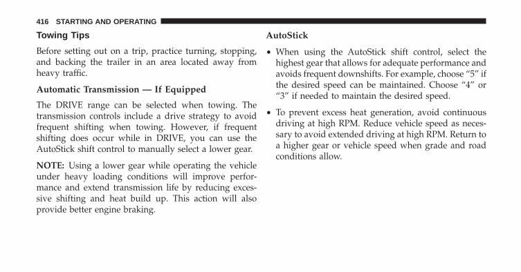
Towing Tips
Before setting out on a trip, practice turning, stopping,and backing the trailer in an area located away fromheavy traffic.
Automatic Transmission — If Equipped
The DRIVE range can be selected when towing. Thetransmission controls include a drive strategy to avoidfrequent shifting when towing. However, if frequentshifting does occur while in DRIVE, you can use theAutoStick shift control to manually select a lower gear.
NOTE: Using a lower gear while operating the vehicleunder heavy loading conditions will improve perfor-mance and extend transmission life by reducing exces-sive shifting and heat build up. This action will alsoprovide better engine braking.
AutoStick
• When using the AutoStick shift control, select thehighest gear that allows for adequate performance andavoids frequent downshifts. For example, choose “5” ifthe desired speed can be maintained. Choose “4” or“3” if needed to maintain the desired speed.
• To prevent excess heat generation, avoid continuousdriving at high RPM. Reduce vehicle speed as neces-sary to avoid extended driving at high RPM. Return toa higher gear or vehicle speed when grade and roadconditions allow.
416 STARTING AND OPERATING

Electronic Speed Control — If Equipped
• Do not use in hilly terrain or with heavy loads.
• When using the speed control, if you experience speeddrops greater than 10 mph (16 km/h), disengage untilyou can get back to cruising speed.
• Use speed control in flat terrain and with light loads tomaximize fuel efficiency.
Cooling System
To reduce potential for engine and transmission over-heating, take the following actions:
City Driving
When stopped for short periods of time, shift the trans-mission into NEUTRAL and increase engine idle speed.
Highway Driving
Reduce speed.
Air Conditioning
Turn off temporarily.
7
STARTING AND OPERATING 417

RECREATIONAL TOWING
Towing This Vehicle Behind Another Vehicle
FRONT WHEEL DRIVE (FWD)FOUR-WHEELDRIVE (4WD)
TOWINGCONDITION
WHEELS OFF THEGROUND
AUTOMATICTRANSMISSION
MANUALTRANSMISSION
MANUAL/AUTOMATIC
TRANSMISSIONFlat Tow NONE NOT ALLOWED NOT ALLOWED NOT ALLOWED
Dolly Tow REAR NOT ALLOWED NOT ALLOWED NOT ALLOWEDFRONT OK OK NOT ALLOWED
On Trailer ALL BEST METHOD BEST METHOD OK
NOTE:
• When recreational towing your vehicle, always followapplicable state and provincial laws. Contact state andprovincial Highway Safety offices for additional de-tails.
• You must ensure that the Auto Park Brake feature isdisabled before towing this vehicle, to avoid inadver-tent Electric Park Brake engagement. The Auto ParkBrake feature is enabled or disabled via the customerprogrammable features in the Uconnect Settings.
418 STARTING AND OPERATING

Recreational Towing
Models With Front-Wheel Drive (FWD)
Recreational towing is allowed ONLY if the front wheelsare OFF the ground. This may be accomplished using atow dolly (front wheels off the ground) or vehicle trailer(all four wheels off the ground). If using a tow dolly,follow this procedure:
• Properly secure the dolly to the tow vehicle, followingthe dolly manufacturer’s instructions.
• Drive the front wheels onto the tow dolly.
• Apply the Electronic Parking Brake (EPB). Place thetransmission in PARK. Turn the engine OFF.
• Properly secure the front wheels to the dolly, followingthe dolly manufacturer’s instructions.
• Turn the ignition to the MAR/RUN position, but donot start the engine.
• Press and hold the brake pedal.
• Release the Electric Park Brake (EPB).
• Turn the ignition OFF, remove the key, and release thebrake pedal.
CAUTION!
• DO NOT flat tow this vehicle. Damage to thedrivetrain will result. If this vehicle requires tow-ing, make sure the drive wheels are OFF theground.
• Ensure that the Electric Park Brake is released, andremains released, while being towed.
• Towing this vehicle in violation of the above re-quirements can cause severe transmission damage.Damage from improper towing is not covered un-der the New Vehicle Limited Warranty.
7
STARTING AND OPERATING 419

Models With Four-Wheel Drive (4WD)
Recreational towing (with all four wheels on the ground,or using a towing dolly) is NOT ALLOWED. This vehiclemay be towed on a flatbed or vehicle trailer provided allfour wheels are OFF the ground.
CAUTION!
Towing this vehicle with ANY of its wheels on theground can cause severe transmission and/or powertransfer unit damage. Damage from improper towingis not covered under the New Vehicle Limited War-ranty.
420 STARTING AND OPERATING

IN CASE OF EMERGENCY
CONTENTS� HAZARD WARNING FLASHERS . . . . . . . . . . .423
� ASSIST AND 9–1–1 — IF EQUIPPED . . . . . . . .423
� BULB REPLACEMENT . . . . . . . . . . . . . . . . . . .430
▫ General Information. . . . . . . . . . . . . . . . . . . .430
▫ Replacement Bulbs . . . . . . . . . . . . . . . . . . . .431
▫ Replacing Exterior Bulbs . . . . . . . . . . . . . . . .433
▫ Replacing Interior Bulbs . . . . . . . . . . . . . . . . .451
� FUSES . . . . . . . . . . . . . . . . . . . . . . . . . . . . . . .457
▫ General Information. . . . . . . . . . . . . . . . . . . .458
▫ Access To The Fuses . . . . . . . . . . . . . . . . . . .459
▫ Engine Compartment Fuses/Distribution Unit . .460
▫ Body Computer Fuse Center. . . . . . . . . . . . . .466
▫ Rear Cargo Fuse/Relay Distribution Unit. . . . .470
� JACKING AND TIRE CHANGING . . . . . . . . . .472
▫ Jack Location/Spare Tire Stowage . . . . . . . . .473
▫ Preparations For Jacking . . . . . . . . . . . . . . . .474
▫ Jacking Instructions . . . . . . . . . . . . . . . . . . .475
▫ Road Tire Installation . . . . . . . . . . . . . . . . . . .482
� TIRE SERVICE KIT STORAGE . . . . . . . . . . . . . .483
▫ Tire Service Kit — If Equipped . . . . . . . . . . . .483
8
� JUMP STARTING . . . . . . . . . . . . . . . . . . . . . .487
▫ Preparations For Jump Start . . . . . . . . . . . . . .488
▫ Jump Starting Procedure . . . . . . . . . . . . . . . .490
� Enhanced Accident Response System . . . . . . . . .492
▫ System Reset Procedure . . . . . . . . . . . . . . . . .492
� REFUELING IN EMERGENCY . . . . . . . . . . . . .494
� IF YOUR ENGINE OVERHEATS . . . . . . . . . . . .494
� GEAR SELECTOR OVERRIDE . . . . . . . . . . . . .495
� IGNITION KEY REMOVAL OVERRIDE . . . . . . .498
� FREEING A STUCK VEHICLE . . . . . . . . . . . . .500
� TOWING A DISABLED VEHICLE . . . . . . . . . . .502
▫ Front Wheel Drive (FWD). . . . . . . . . . . . . . . .504
▫ Four-Wheel Drive (4WD) . . . . . . . . . . . . . . . .504
� EMERGENCY TOW HOOKS — IF EQUIPPED . .505
422 IN CASE OF EMERGENCY

HAZARD WARNING FLASHERS
The Hazard Warning flasher switch is located on theswitch bank below the radio.
Push the switch to turn on the Hazard WarningFlasher. When the switch is activated, all direc-
tional turn signals will flash on and off to warn oncomingtraffic of an emergency. Push the switch a second time toturn off the Hazard Warning flashers.
This is an emergency warning system and it should notbe used when the vehicle is in motion. Use it when yourvehicle is disabled and it is creating a safety hazard forother motorists.
When you must leave the vehicle to seek assistance, theHazard Warning flashers will continue to operate eventhough the ignition is placed in the STOP/OFF position.
NOTE: With extended use the Hazard Warning flashersmay wear down your battery.
ASSIST AND 9–1–1 — IF EQUIPPED
If equipped, the overhead console contains an ASSISTand a 9-1-1 button.
Driver Assistance Call Buttons
1 — 9–1–1 Button2 — Assist Button
8
IN CASE OF EMERGENCY 423

WARNING!
ALWAYS obey traffic laws and pay attention to theroad. Some Uconnect Access services, including 9-1-1and Assist, will NOT work without an operable1X(voice/data) or 3G(data) network connection.
NOTE:
• Your vehicle may be transmitting data as authorizedby the subscriber.
• The ASSIST and 9–1–1 features operate through theUconnect Access service. These buttons will only op-erate as long as your Uconnect Access service is active.Refer to your “Uconnect Radio supplement” for fur-ther information.
ASSIST Call
The ASSIST Button is used to automatically connect youto any one of the following support centers:
• Roadside Assistance – If you get a flat tire, or need atow, just push the Assist button and you’ll be con-nected to someone who can help. Roadside Assistancewill know what vehicle you’re driving and its location.Additional fees may apply for Roadside Assistance.
• Uconnect Access Customer Care – In-vehicle supportfor Uconnect Access and Uconnect Access Via Mobilefeatures.
• Vehicle Customer Care – Total support for all othervehicle issues.
424 IN CASE OF EMERGENCY

9-1-1 Call
1. Push the 9-1-1 Call button on the overhead console.
NOTE: In case the 9-1-1 Call button is pushed in error,there will be a 10 second delay before the 9-1-1 Callsystem initiates a call to a 9-1-1 operator. To cancel the9-1-1 Call connection, push the 9-1-1 Call button on theoverhead console or press the cancellation button on theDevice Screen. Termination of the 9-1-1 Call will turn thegreen LED light on the overhead console off.
2. The LED light located on the Assist and 9-1-1 buttonsin the overhead console will turn green once you pushthese buttons and will remain on until the call isended.
3. Once a connection between the vehicle and a 9-1-1operator is made, the 9-1-1 Call system may transmitthe following important vehicle information to a 9-1-1operator:
• Indication that the occupant placed a 9-1-1 Call.
• The vehicle brand.
• The last known GPS coordinates of the vehicle.
4. You should be able to speak with the 9-1-1 operatorthrough the vehicle audio system to determine ifadditional help is needed.
WARNING!
ALWAYS obey traffic laws and pay attention to theroad. Some Uconnect Access services, including 9-1-1and Assist, will NOT work without an operable1X(voice/data) or 3G(data) network connection.
8
IN CASE OF EMERGENCY 425

NOTE:
• Your vehicle may be transmitting data as authorizedby the subscriber.
• Once a connection is made between the vehicle’s9-1-1 Call system and the 9-1-1 operator, the 9-1-1operator may be able to open a voice connection withthe vehicle to determine if additional help is needed.Once the 9-1-1 operator opens a voice connectionwith the vehicle’s 9-1-1 Call system, the operatorshould be able to speak with you or other vehicleoccupants and hear sounds occurring in the vehicle.The vehicle’s 9-1-1 Call system will attempt to re-main connected with the 9-1-1 operator until the9-1-1 operator terminates the connection.
5. The 9-1-1 operator may attempt to contact appropriateemergency responders and provide them with impor-tant vehicle information and GPS coordinates.
WARNING!
• If anyone in the vehicle could be in danger (e.g.,fire or smoke is visible, dangerous road conditionsor location), do not wait for voice contact from a9-1-1 operator. All occupants should exit the vehicleimmediately and move to a safe location.
• The 9-1-1 Call system is embedded into the vehi-cle’s electrical system. Do not add aftermarketelectrical equipment to the vehicle’s electrical sys-tem. This may prevent your vehicle from sending asignal to initiate an emergency call. To avoid inter-ference that can cause the 9-1-1 Call system to fail,never add aftermarket equipment (e.g., two-waymobile radio, CB radio, data recorder, etc.) to yourvehicle’s electrical system or modify the antennason your vehicle. IF YOUR VEHICLE LOSES BAT-TERY POWER FOR ANY REASON (INCLUDING
(Continued)
426 IN CASE OF EMERGENCY

WARNING! (Continued)DURING OR AFTER AN ACCIDENT), THEUCONNECT FEATURES, APPS AND SERVICES,AMONG OTHERS, WILL NOT OPERATE.
• Modifications to any part of the 9-1-1 Call systemcould cause the air bag system to fail when youneed it. You could be injured if the air bag systemis not there to help protect you.
9-1-1 Call System Limitations
Vehicles sold in Canada and Mexico DO NOT have 9-1-1Call system capabilities.
9-1-1 or other emergency line operators in Canada andMexico may not answer or respond to 9-1-1 system calls.
If the 9-1-1 Call system detects a malfunction, any of thefollowing may occur at the time the malfunction isdetected, and at the beginning of each ignition cycle:
• The overhead console lights located on the Assist and9-1-1 buttons will continuously be illuminated red.
• The Device Screen will display the following message“Vehicle device requires service. Please contact yourdealer.”
• An In-Vehicle Audio message will state “Vehicle de-vice requires service. Please contact your dealer.”
8
IN CASE OF EMERGENCY 427

WARNING!
• Ignoring the Assist and 9-1-1 buttons light couldmean you will not have 9-1-1 Call services. If theAssist and 9-1-1 buttons light is illuminated, havean authorized dealer service the 9-1-1 Call systemimmediately.
• The Occupant Restraint Control module turns onthe air bag Warning Light on the instrument panelif a malfunction in any part of the system isdetected. If the air bag Warning Light is illumi-nated, have an authorized dealer service the ORCsystem immediately.
Even if the 9-1-1 Call system is fully functional, factorsbeyond FCA US LLC’s control may prevent or stop the9-1-1 Call system operation. These include, but are notlimited to, the following factors:
• The ignition key has been removed from the ignitionand the delayed accessories mode is active.
• The ignition key is in STOP/OFF position.
• The vehicle’s electrical systems are not intact.
• The 9-1-1 Call system software and/or hardware aredamaged during a crash.
• The vehicle battery loses power or becomes discon-nected during a vehicle crash.
428 IN CASE OF EMERGENCY

• Operable 1X(voice/data) or 3G(data) network and/orGlobal Positioning Satellite signals are unavailable orobstructed.
• Equipment malfunction at the 9-1-1 operator facility.
• Operator error by the 9-1-1 operator.
• Operable 1X(voice/data) or 3G(data) network conges-tion.
• Weather.
• Buildings, structures, geographic terrain, or tunnels.
WARNING!
ALWAYS obey traffic laws and pay attention to theroad. Some Uconnect Access services, including 9-1-1and Assist, will NOT work without an operable1X(voice/data) or 3G(data) network connection.
NOTE:
• Your vehicle may be transmitting data as authorizedby the subscriber
• Never place anything on or near the vehicle’s operable1X(voice/data) or 3G(data) network and GPS anten-nas. You could prevent operable 1X(voice/data) or3G(data) network and GPS signal reception, which canprevent your vehicle from placing an emergency call.Operable 1X(voice/data) or 3G(data) network andGPS signal reception is required for the 9-1-1 Callsystem to function properly.
General Information
This device complies with Part 15 of the FCC Rules.Operation is subject to the following two conditions: (1)This device may not cause harmful interference, and (2)this device must accept any interference received, includ-ing interference that may cause undesired operation.
8
IN CASE OF EMERGENCY 429

BULB REPLACEMENT
General Information
• Before you replace a bulb check the contacts to be surethey are not oxidized.
• Replace the bulbs with the same type and wattage.
• After replacing a light bulb always check the correctorientation.
• Before replacing a bulb that is not functioning checkthat the fuse is intact.
NOTE: Lens fogging can occur under certain atmo-spheric conditions. This will usually clear as atmosphericconditions change to allow the condensation to changeback into a vapor. Turning the lamps on will usuallyaccelerate the clearing process.
430 IN CASE OF EMERGENCY

Replacement Bulbs
Interior Bulbs
Lamps Bulb NumberFront Courtesy Light C5W
Front Courtesy Lights (Sun Visors) C5WRear Dome Light (Models Without Retractable roof) C5WRear Interior Lights (Models With Retractable roof) C5W
Interior Lights W5WDome Light (Glove Compartment) W5W
8
IN CASE OF EMERGENCY 431

Exterior Bulbs
Lamps Bulb NumberLow Beam/High Beam Headlamps H13
Front Position/Daytime Running Lights (DRL ) P21/5WFront Direction Indicator Lamps PY21W
Front Fog Lamps H11Side Indicators (Front And Side View Mirror) WY5W
Tail/Brake Lights/Turn Indicators P21WCenter High Mounted Stop Lamp (CHMSL) LED (Serviced at an Authorized Dealer)
Reverse W16WLicense Plate Lamp W5W
432 IN CASE OF EMERGENCY

Replacing Exterior Bulbs
Headlamps
Hi/Lo Beam Light Halogen
To replace the bulbs proceed as follows:
1. Open the engine compartment and remove the head-lamp bulb cap.
Headlamp Bulb Cap8
IN CASE OF EMERGENCY 433

2. Rotate the headlamp bulb socket counterclockwisethen pull outwards.
3. Push on the locking tab on the headlamp bulb connec-tor and remove the bulb and socket.
Headlamp Bulb Socket Headlamp Bulb Connector
434 IN CASE OF EMERGENCY

4. Install the new headlamp bulb making sure it isproperly locked.
5. Install the headlamp bulb and socket; turn it clockwisemaking sure it is properly locked.
WARNING!
Carry out the operation of replacing lamps only withthe engine off. Also make sure that the engine is cold,to avoid the danger of burns.
Headlamp Bulb8
IN CASE OF EMERGENCY 435

Position Lights/Daytime Running Lights/Fog Lights
To replace the bulbs proceed as follows:
1. Turn the front wheels completely.
2. Use a suitable tool to remove the access door.
Position Light/Daytime Running Light/Fog Light Access
1 — Screws2 — Access Door
436 IN CASE OF EMERGENCY

3. Remove the electrical connectors. 4. Rotate in a counterclockwise direction (on the left-handsocket) or in a clockwise direction (on the right-handsocket) and remove the bulb and bulb socket.
Electrical Connectors
Position Light/Daytime Running Light Assembly
1 — DRL Bulb Socket2 — Turn Signal Bulb Socket
8
IN CASE OF EMERGENCY 437

5. To replace the bulb gently push bulb and rotatecounterclockwise.
6. Insert the new bulb by pushing on it and turning itclockwise. Make sure the bulb is correctly locked inplace.
7. Install the bulb and sockets and rotate them clockwise(right side) and clockwise (left side), making sure thatit is properly locked.
8. Reconnect the electrical connectors.
9. Reinstall the access door.
Front Fog Lights
To replace the bulbs proceed as follows:
1. Turn the front wheels completely.
2. Use a suitable tool to remove the access door.Bulb and Socket Assembly
1 — Bulb2 — Rotate Bulb
438 IN CASE OF EMERGENCY

3. By pushing the electrical connector tab remove theelectrical connector.
Position Light/Daytime Running Light/Fog Light Access
1 — Screws2 — Access Door Fog Light Assembly
1 — Bulb Socket2 — Electrical Connector3 — Bulb
8
IN CASE OF EMERGENCY 439
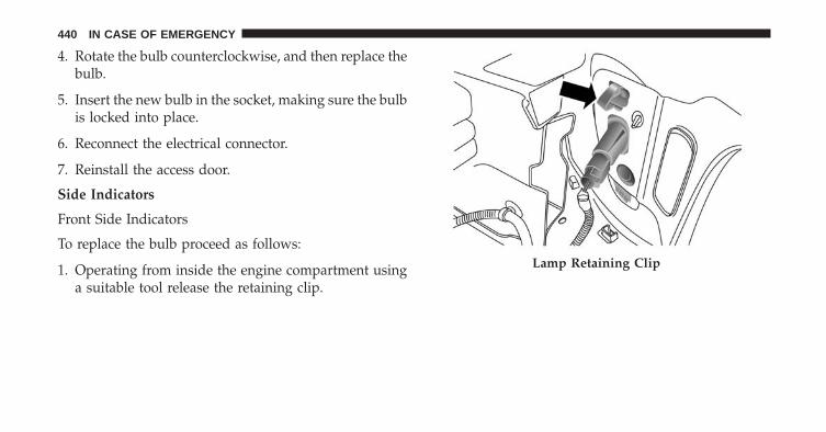
4. Rotate the bulb counterclockwise, and then replace thebulb.
5. Insert the new bulb in the socket, making sure the bulbis locked into place.
6. Reconnect the electrical connector.
7. Reinstall the access door.
Side Indicators
Front Side Indicators
To replace the bulb proceed as follows:
1. Operating from inside the engine compartment usinga suitable tool release the retaining clip.
Lamp Retaining Clip
440 IN CASE OF EMERGENCY

2. Remove lamp assembly by sliding it toward the out-side.
3. Remove the electrical connector by pushing the tabthen disconnect the electrical connector.
Lamp Assembly Electrical Connector
8
IN CASE OF EMERGENCY 441

4. Rotate counterclockwise to release the bulb socketfrom the lamp assembly, and remove it.
5. Remove the bulb from the socket
6. Insert the new bulb in the socket.
7. Reinstall the bulb and socket into the lamp assemblyby turning it clockwise, making sure it is locked intoplace.
Bulb SocketBulb
442 IN CASE OF EMERGENCY

8. Reconnect the electrical connector.
9. Reinstall the lamp assembly on the car, making sure itis locked into place.
Side Indicators on External Rear View Mirrors – (IfEquipped)
CAUTION!
The procedure is described as a guideline. For thereplacement of the lamp it is recommended that youcontact your authorized dealer.
To replace the bulb proceed as follows:
1. Remove the mirror cap on the outside rear viewmirror.
Mirror Cap
8
IN CASE OF EMERGENCY 443

2. Remove the transparent lens assembly as shown.
Removing the mirror capTransparent Lens
444 IN CASE OF EMERGENCY
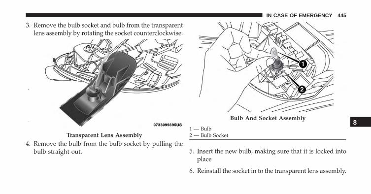
3. Remove the bulb socket and bulb from the transparentlens assembly by rotating the socket counterclockwise.
4. Remove the bulb from the bulb socket by pulling thebulb straight out. 5. Insert the new bulb, making sure that it is locked into
place
6. Reinstall the socket in to the transparent lens assembly.
Transparent Lens Assembly
Bulb And Socket Assembly
1 — Bulb2 — Bulb Socket
8
IN CASE OF EMERGENCY 445

7. Reinstall the cover on the outside rear view mirror,making sure it is locked into place.
Rear Tail Lamps
Contain the following:
• Position lights
• Stop lights
• Direction indicator
• REVERSE lights
To replace the bulbs proceed as follows:
1. Open the liftgate.
2. Using a suitable tool remove the door as shown.3. Using a suitable tool remove fastener.
Trim Panel Door
446 IN CASE OF EMERGENCY

4. Disconnect the electrical connector by pushing therelease.
5. Remove the rear tail lamp, sliding it toward theoutside as shown.
Rear Lamp Fastener and Electrical Connector
1 — Fastener2 — Electrical Connector
Tail Lamp Removal
8
IN CASE OF EMERGENCY 447
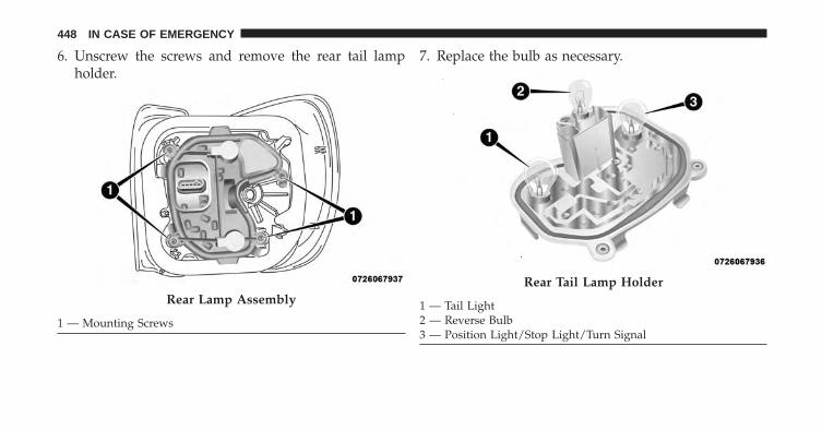
6. Unscrew the screws and remove the rear tail lampholder.
7. Replace the bulb as necessary.
Rear Lamp Assembly
1 — Mounting Screws
Rear Tail Lamp Holder
1 — Tail Light2 — Reverse Bulb3 — Position Light/Stop Light/Turn Signal
448 IN CASE OF EMERGENCY
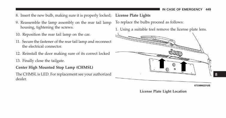
8. Insert the new bulb, making sure it is properly locked;
9. Reassemble the lamp assembly on the rear tail lamphousing, tightening the screws.
10. Reposition the rear tail lamp on the car.
11. Secure the fastener of the rear tail lamp and reconnectthe electrical connector.
12. Reinstall the door making sure of its correct locked
13. Finally close the tailgate.
Center High Mounted Stop Lamp (CHMSL)
The CHMSL is LED. For replacement see your authorizeddealer.
License Plate Lights
To replace the bulbs proceed as follows:
1. Using a suitable tool remove the license plate lens.
License Plate Light Location
8
IN CASE OF EMERGENCY 449

2. Remove the bulbs from the individual side contacts.
3. Insert the new bulbs, and ensure that they are properlylocked between the contacts.
4. Reinstall the license plate lens.
NOTE: If removal the license plate lens using a screw-driver, be sure to cover the tip of the screwdriver with acloth so no damage is done to the lenses or the vehiclepaint.
License Plate Light
450 IN CASE OF EMERGENCY
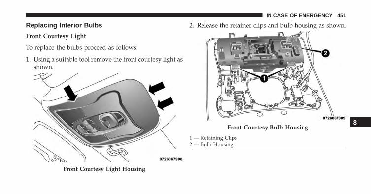
Replacing Interior Bulbs
Front Courtesy Light
To replace the bulbs proceed as follows:
1. Using a suitable tool remove the front courtesy light asshown.
2. Release the retainer clips and bulb housing as shown.
Front Courtesy Light Housing
Front Courtesy Bulb Housing
1 — Retaining Clips2 — Bulb Housing
8
IN CASE OF EMERGENCY 451

3. Replace the bulbs by pulling straight out of bulbhousing.
4. Insert the new bulbs, making sure that they areproperly locked.
5. Reassemble the bulb housing and courtesy light hous-ing making sure that they are properly locked.
6. Install the front courtesy light making sure that it isproperly locked.
Dome Light Vanity Mirror
To replace the bulbs proceed as follows:
1. Lift the cover of the mirror and pull out the visormirror light cover.
2. Replace the bulb, releasing it from the side contacts,and then insert the new bulb, making sure that it isproperly locked between the contacts.
Front Courtesy Bulb Housing
452 IN CASE OF EMERGENCY
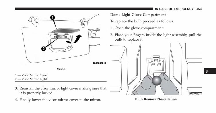
3. Reinstall the visor mirror light cover making sure thatit is properly locked.
4. Finally lower the visor mirror cover to the mirror.
Dome Light Glove Compartment
To replace the bulb proceed as follows:
1. Open the glove compartment;
2. Place your fingers inside the light assembly, pull thebulb to replace it.
Visor
1 — Visor Mirror Cover2 — Visor Mirror Light
Bulb Removal/Installation
8
IN CASE OF EMERGENCY 453

3. Insert the new bulb, making sure it is properly locked.
Rear Dome Light — Without Retractable Roof
To replace the bulbs proceed as follows:
1. Using a suitable tool release the lamp assembly at boththe ends.
2. Open the flap and replace the bulb.
3. Insert the new bulb, locking it between the contacts.
4. Reinstall the dome light.
Rear Dome Light Housing
1 — Bulb2 — Flap
454 IN CASE OF EMERGENCY

Dome Light — MY SKY
To replace the bulbs proceed as follows:
1. Lower the handle in the direction shown remove thedome light.
2. Replace the bulb by removing it from the side contacts.
3. Insert the new bulb, locking it between the contacts.
4. Reinstall the dome light.
Retractable Roof Light
Bulb8
IN CASE OF EMERGENCY 455

Interior Cargo Lights
To replace the bulbs proceed as follows:
1. Open the luggage compartment and remove the domelight assembly.
2. Open the light cover and replace the bulb.
3. Close the light cover over the bulb.
4. Reinstall the dome light in its correct position.
WARNING!
• Before proceeding with the replacement of thelamp wait for the exhaust pipes are cool: DANGEROF BURNS!
• Modifications or repair of the electrical systemperformed incorrectly and without taking into ac-count the technical characteristics can cause mal-functions with the risk of fire.
• Halogen lamps contain gas under pressure, in theevent of breakage be careful of the projection offragments of glass.
(Continued)
Light Cover
456 IN CASE OF EMERGENCY

WARNING! (Continued)• Halogen lamps must be handled by touching only
the metallic part. If the transparent bulb is incontact with the fingers, reduces the intensity ofthe emitted light and you can also affect the life ofthe lamp. In case of accidental contact, rub the bulbwith a cloth dampened with alcohol and allow todry.
FUSES
WARNING!
• When replacing a blown fuse, always use an ap-propriate replacement fuse with the same amprating as the original fuse. Never replace a fusewith another fuse of higher amp rating. Never
(Continued)
WARNING! (Continued)replace a blown fuse with metal wires or any othermaterial. Failure to use proper fuses may result inserious personal injury, fire and/or property dam-age.
• Before replacing a fuse, make sure that the ignitionis off and that all the other services are switched offand/or disengaged.
• If the replaced fuse blows again, contact an autho-rized dealer.
• If a general protection fuse for safety systems (airbag system, braking system), power unit systems(engine system, gearbox system) or steering systemblows, contact an authorized dealer.
8
IN CASE OF EMERGENCY 457

General Information
The fuses protect electrical systems against excessivecurrent.
When a device does not work you must check theelectrical circuit inside the fuse for a break/melt.
Also please be aware that when using power outlets forextended periods of time with the engine off may resultin vehicle battery discharge.
Blade Fuses
1 — Electrical Circuit2 — Blade Fuse With Good Electrical Circuit3 — Blade Fuse With Bad Electrical Circuit
458 IN CASE OF EMERGENCY

Fuse Removal
To replace a fuse use the extractor attached to the fusecover (located on the inside of the engine compartmentfuse cover.
Access To The Fuses
The fuses are grouped into four controllers located in theengine compartment, under the instrument panel and onthe inside of the left side cargo trim panel.
Fuse Extractor Location
8
IN CASE OF EMERGENCY 459

Engine Compartment Fuses/Distribution Unit
The engine compartment fuse panel is located on the leftside of the engine compartment.
Engine Compartment Fuse Cavities
Fuse Panel & Cover Location
1 — Mounting Screw2 — Fuse Cover
460 IN CASE OF EMERGENCY

Removing Fuse Cover and Locking Screw
Proceed as follows:
• Slowly turn the screw counterclockwise.
• Slowly release the screw.
• Remove the fuse cover by sliding it upward.
Mounting Fuse Cover and Locking Screw
Proceed as follows:
• Properly secure the fuse cover to the box, slide com-pletely from top to bottom.
• Fully depress the screw, using the special screwdriversupplied.
• Slowly turn the screw clockwise.
• Release the screw.
Battery Fuse Cover Location
1 — Fuse Cover Tabs2 — Fuse Cover
8
IN CASE OF EMERGENCY 461

Cavity Maxi Fuse Cartridge Fuse Micro Fuse DescriptionF01 70 Amp Tan – – Module Body ComputerF02 70 Amp Tan – – Module Body
Computer, RearDistribution Units
F03 – 20 Amp Blue – Controller Power Sup-ply Body Computer
F04 – 30 Amp Pink – Brake ControlElectronics Module
F05 70 Amp Tan – – Electric Power-AssistedSteering
F06 20 Amp Yellow – – Engine Cooling fanF07 40 Amp Orange – 1.4
Without A/C50 Amp Red – 1.4
With A/C And All 2.4Models
– – Engine Cooling fan
462 IN CASE OF EMERGENCY

Cavity Maxi Fuse Cartridge Fuse Micro Fuse DescriptionF08 – 30 Amp Pink – Automatic
Transmission, GSMF09 – – 5 Amp Tan Control Module EngineF10 – – 15 Amp Blue HornF11 – – 10 Amp Red – 1.4 En-
gines25 Amp Clear – 2.4
Engines
Supply SecondaryLoads
F14 – – 7.5 Amp Brown Heater �Blow By�
F14 – – 5 Amp Tan Pump Power �AfterRun�
F15 40 Amp Orange – – Brake Control ModulePump
F16 – – 5 Amp Tan Engine Control ModulePower, Automatic
Transmission
8
IN CASE OF EMERGENCY 463

Cavity Maxi Fuse Cartridge Fuse Micro Fuse DescriptionF17 – – 10 Amp Red – 1.4 En-
gines15 Amp Blue – 2.4 En-
gines
Supply Primary Loads
F18 – – 20 Amp Yellow 12V Rear Cargo OutletIgnition Powered
F19 – – 7.5 Amp Brown Air ConditionerCompressor
F20 – – 5 Amp Tan Electronic PowerFour-Wheel Drive
F21 – – 15 Amp Blue Fuel PumpF22 – – 20 Amp Yellow Power Control Module
EngineF23 – – 30 Amp Green Heated Windshield –
If Equipped
464 IN CASE OF EMERGENCY

Cavity Maxi Fuse Cartridge Fuse Micro Fuse DescriptionF24 – – 15 Amp Blue Electronic Unit Supply
AutomaticTransmission
F30 – – 20 Amp Yellow (Cus-tomer Installed)
12V Rear Cargo OutletConstant Battery
PoweredF83 – 40 Amp Green – Air Conditioning FanF84 – – 30 Amp Green Power Supply All
Wheel DriveF87 – – 5 Amp Tan Gear Selector Auto-
matic TransmissionF88 – – 7.5 Amp Brown Heated Outside
MirrorsF89 – – 30 Amp Green Heated Rear WindowF90 – – 5 Amp Tan IBS Sensor (Battery
State Of Charge)
8
IN CASE OF EMERGENCY 465

Body Computer Fuse Center
The controller is located at the left side of the steeringcolumn at the bottom of the instrument panel.
For the fuse replacement see your authorized dealer.
466 IN CASE OF EMERGENCY

Body Controller Fuse Cavities
8
IN CASE OF EMERGENCY 467

Cavity Mini Fuse DescriptionF31 7.5 Amp Brown Flashes/Electrical Movement Front
Seats/Fan Air ConditioningF33 20 Amp Yellow Power Window Front (Driver Side)F34 20 Amp Yellow Power Window Front (Passenger Side)F36 15 Amp Blue Supply Uconnect System, Air Con-
ditioning, Alarm, Power FoldingOutside Mirrors, USB Port
F37 10 Amp Red System Power Forward CollisionWarning Plus, All Wheel Drive(AWD), IPC
F38 20 Amp Yellow Central LockingF42 7.5 Amp Brown Power Under Lock and KeyF43 20 Amp Yellow Bi-directional Pump WasherF47 20 Amp Yellow Power Rear Window (Driver Side)F48 20 Amp Yellow Power Rear Window (Passenger
Side)
468 IN CASE OF EMERGENCY

Cavity Mini Fuse DescriptionF49 7.5 Amp Brown Supply ParkSense, Spot Lights
Front Dome, Mirror, Electric MotorRetractable Roof, Heated FrontSeats, Stabilizer Battery, ESC Sys-tem, ESL
F50 7.5 Amp Brown Supply Air BagF51 7.5 Amp Brown Alarm Power, Front Courtesy
Light, Air Conditioning Compres-sor, Brake Pedal Switch (NC),Plaque Automatic Transmission,Compass, Rear Camera, LevelingHeadlights, Air Conditioning
F53 7.5 Amp Brown Supply IPC/Starter Device/SystemKeyless Enter-N-Go
F94 15 Amp Blue Power Socket
8
IN CASE OF EMERGENCY 469
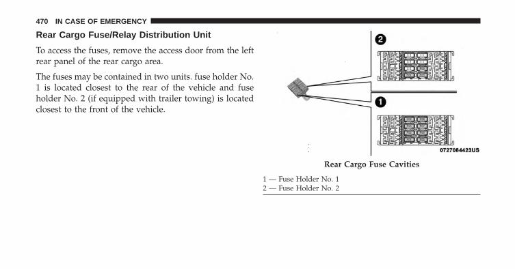
Rear Cargo Fuse/Relay Distribution Unit
To access the fuses, remove the access door from the leftrear panel of the rear cargo area.
The fuses may be contained in two units. fuse holder No.1 is located closest to the rear of the vehicle and fuseholder No. 2 (if equipped with trailer towing) is locatedclosest to the front of the vehicle.
Rear Cargo Fuse Cavities
1 — Fuse Holder No. 12 — Fuse Holder No. 2
470 IN CASE OF EMERGENCY

Fuse Holder No. 1
Cavity Mini Fuse DescriptionF1 30 Amp Blue Power InverterF2 20 Amp Yellow HIFI Audio SystemF3 20 Amp Yellow MY SKYF4 7.5 Amp Brown Lumbar Adjustment Front Seat
(Driver Side)F5 30 Amp Green Power Seat (Driver Side)F6 7.5 Amp Brown Power Seat (Driver Side And Pas-
senger Side)F7 30 Amp Green Lumbar Adjustment Front Seats
(Driver Side And Passenger Side)F8 20 Amp Yellow Heating Front Seats
On the controller there is also a 20 amp fuse for the sunvisor of the retractable roof.
8
IN CASE OF EMERGENCY 471

Fuse Holder No. 2
Cavity Mini Fuse DescriptionF1 10 Amp Red Controller Exterior Lighting On TrailerF5 15 Amp Blue Controller Exterior Lighting Lights (Drivers Side)F6 15 Amp Blue Controller Exterior Lighting Lights (Passenger Side)
JACKING AND TIRE CHANGING
WARNING!
• Do not attempt to change a tire on the side of thevehicle close to moving traffic. Pull far enough offthe road to avoid the danger of being hit whenoperating the jack or changing the wheel.
• Being under a jacked-up vehicle is dangerous. Thevehicle could slip off the jack and fall on you. Youcould be crushed. Never put any part of your bodyunder a vehicle that is on a jack. If you need to get
(Continued)
WARNING! (Continued)under a raised vehicle, take it to a service centerwhere it can be raised on a lift.
• Never start or run the engine while the vehicle ison a jack.
• The jack is designed to be used as a tool forchanging tires only. The jack should not be used tolift the vehicle for service purposes. The vehicleshould be jacked on a firm level surface only.Avoid ice or slippery areas.
472 IN CASE OF EMERGENCY

Jack Location/Spare Tire Stowage
The jack and tools are located in the rear storage com-partment if equipped, inside a special container.
1. Open the liftgate.
2. Lift the access cover using the load floor pull strap.
3. Remove the fastener securing the spare tire.
4. Remove the chocks.
5. Remove the jack and wheel bolt wrench.
Jack And Tools
1 — Wheel Bolt Wrench2 — Jack3 — Emergency Funnel
4 — Wheel Chocks5 — Screwdriver6 — Emergency Allen Key
Load Floor Pull Strap
8
IN CASE OF EMERGENCY 473
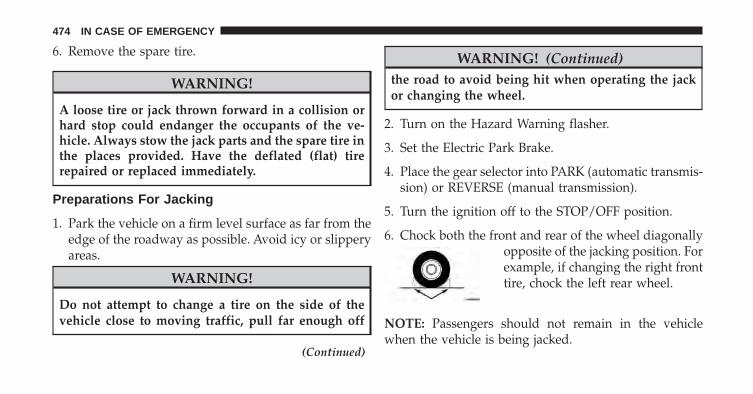
6. Remove the spare tire.
WARNING!
A loose tire or jack thrown forward in a collision orhard stop could endanger the occupants of the ve-hicle. Always stow the jack parts and the spare tire inthe places provided. Have the deflated (flat) tirerepaired or replaced immediately.
Preparations For Jacking
1. Park the vehicle on a firm level surface as far from theedge of the roadway as possible. Avoid icy or slipperyareas.
WARNING!
Do not attempt to change a tire on the side of thevehicle close to moving traffic, pull far enough off
(Continued)
WARNING! (Continued)the road to avoid being hit when operating the jackor changing the wheel.
2. Turn on the Hazard Warning flasher.
3. Set the Electric Park Brake.
4. Place the gear selector into PARK (automatic transmis-sion) or REVERSE (manual transmission).
5. Turn the ignition off to the STOP/OFF position.
6. Chock both the front and rear of the wheel diagonallyopposite of the jacking position. Forexample, if changing the right fronttire, chock the left rear wheel.
NOTE: Passengers should not remain in the vehiclewhen the vehicle is being jacked.
474 IN CASE OF EMERGENCY

Jacking Instructions
WARNING!Carefully follow these tire changing warnings to helpprevent personal injury or damage to your vehicle:• Always park on a firm, level surface as far from the
edge of the roadway as possible before raising thevehicle.
• Turn on the Hazard Warning flasher.• Chock the wheel diagonally opposite the wheel to
be raised.• Apply the parking brake and place an automatic
transmission in PARK.• Never start or run the engine with the vehicle on a jack.• Do not let anyone sit in the vehicle when it is on a jack.• Do not get under the vehicle when it is on a jack. If
you need to get under a raised vehicle, take it to aservice center where it can be raised on a lift.
(Continued)
WARNING! (Continued)• Only use the jack in the positions indicated and for
lifting this vehicle during a tire change.• If working on or near a roadway, be extremely
careful of motor traffic.• To assure that spare tires, flat or inflated, are
securely stowed, spares must be stowed with thevalve stem facing the ground.
Jack Warning Label
8
IN CASE OF EMERGENCY 475

CAUTION!
Do not attempt to raise the vehicle by jacking onlocations other than those indicated in the JackingInstructions for this vehicle.
1. Remove the spare tire, jack, and wheel bolt wrench.
2. If equipped with wheels where the center cap coversthe wheel bolts, use the wheel bolt wrench to pry thecenter cap off carefully before raising the vehicle.
3. Before raising the vehicle, use the wheel bolt wrenchto loosen, but not remove, the wheel bolts on thewheel with the flat tire. Turn the wheel bolts counter-clockwise one turn while the wheel is still on theground.
4. Place the jack underneath the jacking location that isclosest to the flat tire. Jacking location is indicated bya stamped arrow on the body. Turn the jack screw
clockwise to firmly engage the jack saddle with the liftarea of the sill flange, centering the jack saddle insidethe cutout in the sill cladding.
Jacking Locations
476 IN CASE OF EMERGENCY

Front Jacking Location Front Jacking Engagement Point8
IN CASE OF EMERGENCY 477

5. Raise the vehicle just enough to remove the flat tire.Rear Jacking Location Rear Jacking Engagement Point
478 IN CASE OF EMERGENCY

WARNING!
Raising the vehicle higher than necessary can makethe vehicle less stable. It could slip off the jack andhurt someone near it. Raise the vehicle only enoughto remove the tire.
6. Remove the wheel bolts and tire.
7. Mount the spare tire.
CAUTION!
Be sure to mount the spare tire with the valve stemfacing outward. The vehicle could be damaged if thespare tire is mounted incorrectly.
Mounting Spare Tire8
IN CASE OF EMERGENCY 479

NOTE:
• Your vehicle may be equipped with a compact sparetire or a limited — use spare tire. For further infor-mation refer to “Tires — General Information” in“Maintaining And Caring For Your Vehicle”.
• For vehicles so equipped, do not attempt to install acenter cap or wheel cover on the compact spare.
8. Install the wheel bolts with the threaded end of thewheel bolt toward the wheel. Lightly tighten thewheel bolts.
WARNING!
To avoid the risk of forcing the vehicle off the jack,do not fully tighten the wheel bolts until the vehiclehas been lowered. Failure to follow this warning mayresult in serious injury.
9. Lower the vehicle to the ground by turning the jackhandle counterclockwise.
10. Finish tightening the wheel bolts. Push down on thewrench while at the end of the handle for increasedleverage. Tighten the wheel bolts in a star patternuntil each wheel bolt has been tightened twice. Referto “Torque Specifications” in this section for theproper lug bolt torque. If in doubt about the correcttightness, have them checked with a torque wrenchby your authorized dealer or at a service station.
480 IN CASE OF EMERGENCY

11. Securely stow the jack, tools, chocks and flat tire. WARNING!
A loose tire or jack thrown forward in a collision orhard stop could endanger the occupants of the ve-hicle. Always stow the jack parts and the spare tire inthe places provided. Have the deflated (flat) tirerepaired or replaced immediately.
Properly Stowed Tire8
IN CASE OF EMERGENCY 481

Road Tire Installation
1. Mount the road tire on the axle.
2. Install the remaining wheel bolts with the threadedend of the wheel bolt toward the wheel. Lightlytighten the wheel bolts.
WARNING!
To avoid the risk of forcing the vehicle off the jack,do not tighten the lug nuts fully until the vehicle hasbeen lowered. Failure to follow this warning mayresult in serious injury.
3. Lower the vehicle to the ground by turning the jackhandle counterclockwise.
4. Finish tightening the wheel bolts. Push down on thewrench while at the end of the handle for increasedleverage. Tighten the wheel bolts in a star pattern untileach wheel bolt has been tightened twice. Refer to“Torque Specifications” in the “Technical Data” sec-tion for the proper lug bolt torque. If in doubt aboutthe correct tightness, have them checked with a torquewrench by your authorized dealer or service station.
5. Lower the jack until it is free. Remove the wheelchocks. Stow the jack and tools back in the properstorage location. Release the Electric Park Brake beforedriving the vehicle.
6. After 25 miles (40 km) check the wheel bolt torquewith a torque wrench to ensure that all wheel bolts areproperly seated against the wheel.
482 IN CASE OF EMERGENCY

TIRE SERVICE KIT STORAGE
The Tire Service Kit is located in the rear storage com-partment inside a storage container. Located inside thecontainer are a screwdriver and the emergency fuelfunnel. To access the Tire Service Kit open the liftgate andremove the load floor.
Tire Service Kit — If Equipped
Tire Service Kit Components
1 — Power Plug (located on bottom side of Tire Service Kit)2 — Sealant Hose (Clear)3 — Power Button4 — Pressure Gauge5 — Sealant Bottle
8
IN CASE OF EMERGENCY 483

If a tire is punctured, you can make a first emergencyrepair using the Tire Service Kit located in the rearstorage compartment inside the storage container.
Remove the Tire Service Kit from the vehicle, take it outfrom the bag and place it near the punctured tire. Screwthe clear flexible filling tube to the tire valve.
WARNING!
• Do not attempt to seal a tire on the side of thevehicle closest to traffic. Pull far enough off theroad to avoid the danger of being hit when usingthe Tire Service Kit.
• Do not use Tire Service Kit or drive the vehicleunder the following circumstances:– If the puncture in the tire tread is approximately
1/4 inch (6 mm) or larger.– If the tire has any sidewall damage.
(Continued)
WARNING! (Continued)– If the tire has any damage from driving with
extremely low tire pressure.– If the tire has any damage from driving on a flat
tire.– If the wheel has any damage.– If you are unsure of the condition of the tire or
the wheel.• Keep Tire Service Kit away from open flames or
heat source.• A loose Tire Service Kit thrown forward in a
collision or hard stop could endanger the occupantsof the vehicle. Always stow the Tire Service Kit inthe place provided. Failure to follow these warn-ings can result in injuries that are serious or fatal toyou, your passengers, and others around you.
(Continued)
484 IN CASE OF EMERGENCY

WARNING! (Continued)• Take care not to allow the contents of Tire Service
Kit to come in contact with hair, eyes, or clothing.Tire Service Kit sealant is harmful if inhaled,swallowed, or absorbed through the skin. It causesskin, eye, and respiratory irritation. Flush immedi-ately with plenty of water if there is any contactwith eyes or skin. Change clothing as soon aspossible, if there is any contact with clothing.
• Tire Service Kit Sealant solution contains latex. Incase of an allergic reaction or rash, consult a phy-sician immediately. Keep Tire Service Kit out ofreach of children. If swallowed, rinse mouth imme-diately with plenty of water and drink plenty ofwater. Do not induce vomiting! Consult a physicianimmediately.
Insert the power plug into the vehicle power outletsocket. Start the vehicle engine.
Push the Tire Service Kit power button to the “I” position.The electric compressor will be turned on, sealant and airwill inflate the tire.
Minimum 26 psi (1.8 bar) of pressure should be reachedwithin 20 minutes. If the pressure has not been reachedturn off and remove the Tire Service Kit, drive the vehicle30 feet (10 meters) back and forth, to better distribute thesealant inside the tire.
Attach the clear flexible filling tube of the compressordirectly to the tire valve and repeat the inflation process.
When the correct pressure has been reached, start drivingthe vehicle to uniformly distribute the sealant inside thetire. After 10 minutes, stop and check the tire pressure. Ifthe pressure is below 19 psi (1.3 bar), do not drive thevehicle, as the tire is too damaged, contact the nearestAuthorized Dealer.
8
IN CASE OF EMERGENCY 485

WARNING!
Tire Service Kit is not a permanent flat tire repair.Have the tire inspected and repaired or replaced afterusing Tire Service Kit. Do not exceed 65 mph (110km/h) until the tire is repaired or replaced. Failure tofollow this warning can result in injuries that areserious or fatal to you, your passengers, and othersaround you. Have the tire checked as soon as pos-sible at an Authorized Dealer.
If the pressure is at 19 psi (1.3 bar) or above repeat theinflation process to reach the correct tire pressure andcontinue driving.
Peel off the warning label from the bottle and place it onthe dashboard as a reminder to the driver that the tire hasbeen treated with Tire Service Kit.
WARNING!
The metal end fitting from Power Plug may get hotafter use, so it should be handled carefully.
NOTE: Replace the sealant canister prior to the expira-tion date at your authorized dealer.
486 IN CASE OF EMERGENCY

WARNING!
Store the sealant canister in its special compartment,away from sources of heat. Failure to follow thisWARNING may result in sealant canister ruptureand serious injury or death.
JUMP STARTING
If your vehicle has a discharged battery it can be jump-started using a set of jumper cables and a battery inanother vehicle or by using a portable battery boosterpack. Jump starting can be dangerous if done improperlyso please follow the procedures in this section carefully.
NOTE: When using a portable battery booster packfollow the manufacturer’s operating instructions andprecautions.
WARNING!
Do not attempt jump starting if the battery is frozen.It could rupture or explode and cause personal injury.
Tire Service Kit Expiration Date Location8
IN CASE OF EMERGENCY 487

CAUTION!
Do not use a portable battery booster pack or anyother booster source with a system voltage greaterthan 12 Volts or damage to the battery, starter motor,alternator or electrical system may occur.
Preparations For Jump Start
The battery in your vehicle is located in the front of theengine compartment, behind the left headlight assembly.
Battery Posts
1 — Positive Battery Post2 — Negative Battery Post
488 IN CASE OF EMERGENCY

NOTE: The positive battery post is covered with aprotective cap. Lift up on the cap to gain access to thepositive battery post.
WARNING!
• Take care to avoid the radiator cooling fan when-ever the hood is raised. It can start anytime theignition switch is ON. You can be injured bymoving fan blades.
• Remove any metal jewelry such as rings, watchbands and bracelets that could make an inadvertentelectrical contact. You could be seriously injured.
• Batteries contain sulfuric acid that can burn yourskin or eyes and generate hydrogen gas which isflammable and explosive. Keep open flames orsparks away from the battery.
Proceed as follows:
1. Set the Electric Park Brake, shift the automatic trans-mission into PARK (manual transmission in NEU-TRAL) and turn the ignition to STOP/OFF.
2. Turn off the heater, radio, and all unnecessary electri-cal accessories.
3. If using another vehicle to jump start the battery, parkthe vehicle within the jumper cables reach, set theparking brake and make sure the ignition is STOP/OFF.
WARNING!
Do not allow vehicles to touch each other as thiscould establish a ground connection and personalinjury could result.
8
IN CASE OF EMERGENCY 489

Jump Starting Procedure
WARNING!
Failure to follow this jump-starting procedure couldresult in personal injury or property damage due tobattery explosion.
CAUTION!
Failure to follow these procedures could result indamage to the charging system of the booster vehicleor the discharged vehicle.
Connecting The Jumper Cables
1. Connect the positive (+) end of the jumper cable to thepositive (+) post of the discharged vehicle.
2. Connect the opposite end of the positive (+) jumpercable to the positive (+) post of the booster battery.
3. Connect the negative (-) end of the jumper cable to thenegative (-) post of the booster battery.
4. Connect the opposite end of the negative (-) jumpercable to a good engine ground (exposed metal part ofthe discharged vehicle’s engine) away from the batteryand the fuel injection system.
WARNING!
Do not connect the jumper cable to the negative (-)post of the discharged battery. The resulting electri-cal spark could cause the battery to explode andcould result in serious injury. Only use the specificground point, do not use any other exposed metalparts.
490 IN CASE OF EMERGENCY
5. Start the engine in the vehicle that has the boosterbattery, let the engine idle a few minutes, and thenstart the engine in the vehicle with the dischargedbattery.
6. Once the engine is started, remove the jumper cablesin the reverse sequence:
Disconnecting The Jumper Cables
1. Disconnect the negative (-) end of the jumper cablefrom the engine ground of the vehicle with the dis-charged battery.
2. Disconnect the opposite end of the negative (-) jumpercable from the negative (-) post of the booster battery.
3. Disconnect the positive (+) end of the jumper cablefrom the positive (+) post of the booster battery.
4. Disconnect the opposite end of the positive (+) jumpercable from the positive (+) post of the vehicle with thedischarged battery.
If frequent jump starting is required to start your vehicleyou should have the battery and charging system in-spected at your authorized dealer.
CAUTION!
Accessories plugged into the vehicle power outletsdraw power from the vehicle’s battery, even when notin use (i.e., cellular devices, etc.). Eventually, ifplugged in long enough without engine operation,the vehicle’s battery will discharge sufficiently todegrade battery life and/or prevent the engine fromstarting.
8
IN CASE OF EMERGENCY 491

Enhanced Accident Response System
In the event of an impact, if the communication networkremains intact, and the power remains intact, dependingon the nature of the event, the ORC will determinewhether to have the Enhanced Accident Response Sys-tem perform the following functions:
• Cut off fuel to the engine.
• Flash hazard lights as long as the battery has power oruntil the ignition is placed in the “OFF” position. Thehazard lights flasher can be deactivated by pressingthe hazard flasher button.
• Turn on the interior lights, which remain on as long asthe battery has power or for 15 minutes from theintervention of the Enhanced Accident Response System.
• Unlock the doors automatically.
• Turn off the Fuel Pump Heater.
• Turn Off the HVAC Blower Motor.
• Close the HVAC Circulation Door.
System Reset Procedure
Depending on the nature of the event the left and rightturn signal lights, located in the instrument panel, mayboth be blinking and will continue to blink until theignition switch is turned to the OFF position. After anaccident, turn the ignition switch to STOP/OFF position,check that there aren’t any losses of fuel/liquids. In orderto move your vehicle to the side of the road, you mustfollow the system reset procedure.
492 IN CASE OF EMERGENCY

Customer Action Customer Will See1. Turn ignition OFF.
(Turn Signal Switch Mustbe placed in Neutral
State).2. Turn ignition ON. Left Turn Light is OFF.
Right Turn Light BLINKS.3. Turn Right Turn Signal
Switch ON.Right Turn Light is ONSOLID. Left Turn Light
BLINKS.4. Turn Left Turn Signal
Switch ON.Left Turn Light is ON
SOLID. Right Turn LightBLINKS.
5. Turn Right Turn SignalSwitch ON.
Right Turn Light is ONSOLID. Left Turn Light
BLINKS.
6. Turn Left Turn SignalSwitch ON.
Left Turn Light is ONSOLID. Right Turn Light
is ON SOLID.7. Turn Left Turn SignalSwitch OFF. (Turn SignalSwitch Must be placed in
Neutral State).
Left Turn Light is OFF.Right Turn Light is OFF.
8. Turn ignition OFF.9. Turn Hazard Flashers
OFF (Manually).System is now reset and
the engine may bestarted.
If a reset procedure step is not completed within 60seconds, then the turn signal lights will turn off and thereset procedure must be performed again in order to besuccessful.
8
IN CASE OF EMERGENCY 493

REFUELING IN EMERGENCY
The fuel filling procedure in case of emergency is de-scribed in the “Emergency Refueling Procedure”. Refer to“Adding Fuel” in “Starting And Operating” for furtherinformation.
IF YOUR ENGINE OVERHEATS
In any of the following situations, you can reduce thepotential for overheating your engine by taking theappropriate action.
• On the highways — slow down.
• In city traffic — while stopped, put transmission inNEUTRAL, but do not increase engine idle speed.
CAUTION!
Driving with a hot cooling system could damageyour vehicle. If the temperature gauge reads “H,”pull over and stop the vehicle. Idle the vehicle withthe air conditioner turned off until the pointer dropsback into the normal range. If the pointer remains onthe “H” and you hear continuous chimes, turn theengine off immediately and call for service.
NOTE: There are steps that you can take to slow downan impending overheat condition:• If your air conditioner (A/C) is on, turn it off. The A/C
system adds heat to the engine cooling system andturning the A/C off can help remove this heat.
494 IN CASE OF EMERGENCY

• You can also turn the temperature control to maximumheat, the mode control to floor and the blower controlto high. This allows the heater core to act as asupplement to the radiator and aids in removing heatfrom the engine cooling system.
WARNING!
You or others can be badly burned by hot enginecoolant (antifreeze) or steam from your radiator. Ifyou see or hear steam coming from under the hood,do not open the hood until the radiator has had timeto cool. Never try to open a cooling system pressurecap when the radiator or coolant bottle is hot.
GEAR SELECTOR OVERRIDE
If a malfunction occurs and the gear selector cannot bemoved out of the PARK position, you can use thefollowing procedure to temporarily move the gear selec-tor:
1. Turn the engine OFF.
2. Apply the Electric Park Brake.
8
IN CASE OF EMERGENCY 495

3. Carefully separate the gear selector bezel and bootassembly from the center console.
4. Press and maintain firm pressure on the brake pedal.Gear Selector Bezel Location Removing Gear Selector Bezel
496 IN CASE OF EMERGENCY

5. Insert a small screwdriver or similar tool down intothe gear selector override access hole (at the right frontcorner of the gear selector assembly), and push andhold the override release lever down.
6. Move the Gear Selector to the NEUTRAL position.
7. The vehicle may then be started in NEUTRAL.
8. Reinstall the gear selector bezel.
Gear Selector Override Location
1 — Gear Selector Override Access Hole
8
IN CASE OF EMERGENCY 497

IGNITION KEY REMOVAL OVERRIDE
This vehicle is equipped with a Key Ignition Park Inter-lock which requires the transmission to be in PARKbefore the ignition switch can be turned to the STOP/OFF (key removal) position. To remove the key manually,proceed as follows:
1. Make sure the vehicle is in a safe location and set theElectric Park Brake.
2. Unlock the steering column, and pull the tilt/telescoping control handle down.
3. Pull the steering wheel outward until it is in the end ofthe travel position, then lock the steering column inposition and push the control handle up until fullyengaged.
4. Using the special tool supplied (located in the toolbag), remove the screws in the lower steering columntrim cover and remove it.
Special Tool
498 IN CASE OF EMERGENCY

5. With one hand, pull down on the release tab and withthe other, pull out the ignition key.
Lower Steering Column Cover
1 — Trim Screws
Release Tab Location8
IN CASE OF EMERGENCY 499

6. Once the key is removed, reinstall the steering columncover.
FREEING A STUCK VEHICLE
If your vehicle becomes stuck in mud, sand or snow, itcan often be moved using a rocking motion. Turn thesteering wheel right and left to clear the area around thefront wheels. For vehicles with automatic transmission,push and hold the lock button on the gear selector. Thenshift back and forth between DRIVE and REVERSE (withautomatic transmission) or 2ND GEAR and REVERSE(with manual transmission), while gently pressing theaccelerator.
Use the least amount of accelerator pedal pressure thatwill maintain the rocking motion without spinning thewheels or racing the engine.
For Vehicles With Automatic Transmission:
Shifts between DRIVE and REVERSE can only beachieved at wheel speeds of 5 mph (8 km/h) or less.
Release Tab Direction
500 IN CASE OF EMERGENCY

Whenever the transmission remains in NEUTRAL formore than two seconds, you must press the brake pedalto engage DRIVE or REVERSE.
NOTE: Push the �ESC Off� switch (if necessary), to placethe Electronic Stability Control (ESC) system in �PartialOff� mode, before rocking the vehicle. Refer to “Elec-tronic Brake Control” in “Starting And Operating” forfurther information. Once the vehicle has been freed,push the �ESC Off� switch again to restore �ESC On�mode.
WARNING!
Fast spinning tires can be dangerous. Forces gener-ated by excessive wheel speeds may cause damage, oreven failure, of the axle and tires. A tire couldexplode and injure someone. Do not spin your vehi-cle’s wheels faster than 30 mph (48 km/h) or for
(Continued)
WARNING! (Continued)longer than 30 seconds continuously without stop-ping when you are stuck and do not let anyone neara spinning wheel, no matter what the speed.
CAUTION!
• Racing the engine or spinning the wheels may leadto transmission overheating and failure. Allow theengine to idle with the transmission in NEUTRALfor at least one minute after every five rocking-motion cycles. This will minimize overheating andreduce the risk of clutch or transmission failureduring prolonged efforts to free a stuck vehicle.
• When “rocking” a stuck vehicle by shifting be-tween DRIVE/2nd gear and REVERSE, do not spinthe wheels faster than 15 mph (24 km/h), or drive-train damage may result.
(Continued)
8
IN CASE OF EMERGENCY 501

CAUTION! (Continued)• Revving the engine or spinning the wheels too fast
may lead to transmission overheating and failure.It can also damage the tires. Do not spin the wheelsabove 30 mph (48 km/h) while in gear (no trans-mission shifting occurring).
TOWING A DISABLED VEHICLE
This section describes procedures for towing a disabledvehicle using a commercial towing service.
FWD MODELS FOUR WHEEL DRIVETowing
ConditionWheelsOFF theGround
AUTOMATICTRANSMISSION
MANUAL TRANSMIS-SION
AUTOMATIC/MANUALTRANSMISSION 4X4
Flat Tow NONE NOT ALLOWED NOT ALLOWED NOT ALLOWEDWheel Liftor Dolly
Tow
Rear NOT ALLOWED NOT ALLOWED NOT ALLOWEDFront OK OK NOT ALLOWED
Flatbed ALL BEST METHOD BEST METHOD OK
502 IN CASE OF EMERGENCY

Proper towing or lifting equipment is required to preventdamage to your vehicle. Use only tow bars and otherequipment designed for this purpose, following equip-ment manufacturer’s instructions. Use of safety chains ismandatory. Attach a tow bar or other towing device tomain structural members of the vehicle, not to bumpersor associated brackets. State and local laws regardingvehicles under tow must be observed.
NOTE:
• Vehicles with a discharged battery or total electricalfailure when the Electric Park Brake (EPB) is engaged,will need a wheel dolly or jack to raise the rear wheelsoff the ground when moving the vehicle onto a flatbed.
• You must ensure that the Auto Park Brake feature isdisabled before towing this vehicle, to avoid inadver-tent Electric Park Brake engagement. The Auto ParkBrake feature is enabled or disabled via the customerprogrammable features in the Uconnect Settings.
If you must use the accessories (wipers, defrosters, etc.)while being towed, the ignition must be in the MAR/RUN position. If the key fob is unavailable, or thevehicle’s battery is discharged, refer to “Gear SelectorOverride” in this section for instructions on shifting thetransmission out of PARK so that the vehicle can bemoved.
CAUTION!
• Do not use sling type equipment when towing.Vehicle damage may occur.
• When securing the vehicle to a flat bed truck, donot attach to front or rear suspension components.Damage to your vehicle may result from impropertowing.
8
IN CASE OF EMERGENCY 503

Front Wheel Drive (FWD)
The manufacturer recommends towing your vehicle withall four wheels OFF the ground on a flatbed.
If flatbed equipment is not available, this vehicle musttowed with the front wheels OFF the ground (using atowing dolly, or wheel lift equipment with the frontwheels raised).
NOTE: Ensure that the Electric Park Brake is released,and remains released, while being towed.
CAUTION!
Towing this vehicle in violation of the above require-ments can cause severe transmission damage. Dam-age from improper towing is not covered under theNew Vehicle Limited Warranty.
Four-Wheel Drive (4WD)
The manufacturer requires towing with all four wheelsOFF the ground. Acceptable methods are to tow thevehicle on a flatbed, or with one end of the vehicle raisedand the opposite end on a towing dolly.
CAUTION!
• DO NOT tow this vehicle with ANY of its wheelson the ground. Damage to the drivetrain will result.
• Front or rear wheel lifts must not be used. Internaldamage to the transmission or power transfer unitwill occur if a front or rear wheel lift is used whentowing.
• Towing this vehicle in violation of the above re-quirements can cause severe transmission and/orpower transfer unit damage. Damage from im-proper towing is not covered under the New Ve-hicle Limited Warranty.
504 IN CASE OF EMERGENCY

EMERGENCY TOW HOOKS — IF EQUIPPED
If your vehicle is equipped with tow hooks, there will beone in the rear and two mounted on the front of thevehicle. The rear hook will be located on the driver’s sideof the vehicle.
NOTE: For off-road recovery, it is recommended to useboth of the front tow hooks to minimize the risk ofdamage to the vehicle.
Front Tow Hook Locations8
IN CASE OF EMERGENCY 505

Vehicles Equipped With Key Fob With An IntegratedVehicle Key
Turn the ignition key to the MAR/RUN and then STOP/OFF position, without removing it. By extracting the keythis will automatically engage the steering wheel lock.Place the transmission into NEUTRAL.
Vehicles With Keyless Enter-N-Go
Place the ignition in the RUN and subsequently on STOP,without opening the door. During towing remember thatnot having the aid of the power brakes and the electro-mechanical power steering, greater force is needed inapplying the brakes and steering of the vehicle.
Rear Tow Hook Location
506 IN CASE OF EMERGENCY

WARNING!
• Do not use a chain for freeing a stuck vehicle.Chains may break, causing serious injury or death.
• Stand clear of vehicles when pulling with towhooks. Tow straps may become disengaged, caus-ing serious injury.
CAUTION!
Tow hooks are for emergency use only, to rescue avehicle stranded off road. Do not use tow hooks fortow truck hookup or highway towing. You coulddamage your vehicle.
8
IN CASE OF EMERGENCY 507

MAINTAINING AND CARING FOR YOUR VEHICLE
CONTENTS� EMISSIONS INSPECTION AND
MAINTENANCE PROGRAMS . . . . . . . . . . . . .511
� REPLACEMENT PARTS . . . . . . . . . . . . . . . . . .512
� DEALER SERVICE . . . . . . . . . . . . . . . . . . . . . .512
� MAINTENANCE SCHEDULE . . . . . . . . . . . . .513
▫ Maintenance Chart. . . . . . . . . . . . . . . . . . . . .515
� ENGINE COMPARTMENT — 1.4L TURBOENGINE . . . . . . . . . . . . . . . . . . . . . . . . . . . . .523
� ENGINE COMPARTMENT — 2.4L ENGINE . . . .524
� MAINTENANCE PROCEDURES . . . . . . . . . . .525
▫ Engine Oil . . . . . . . . . . . . . . . . . . . . . . . . . .525
▫ Engine Oil Filter . . . . . . . . . . . . . . . . . . . . . .528
▫ Engine Air Cleaner Filter . . . . . . . . . . . . . . . .529
▫ Maintenance-Free Battery . . . . . . . . . . . . . . .529
▫ Air Conditioner Maintenance . . . . . . . . . . . . .530
▫ Body Lubrication . . . . . . . . . . . . . . . . . . . . .532
▫ Wiper Blades . . . . . . . . . . . . . . . . . . . . . . . .532
▫ Adding Washer Fluid . . . . . . . . . . . . . . . . . .535
▫ Exhaust System . . . . . . . . . . . . . . . . . . . . . .535
▫ Cooling System . . . . . . . . . . . . . . . . . . . . . .538
▫ Brake System . . . . . . . . . . . . . . . . . . . . . . . .544
9

▫ Manual Transmission — If Equipped . . . . . . .546
▫ Automatic Transmission — If Equipped . . . . .547
▫ Appearance Care And Protection FromCorrosion . . . . . . . . . . . . . . . . . . . . . . . . . . .549
� LIFTING A VEHICLE . . . . . . . . . . . . . . . . . . .557
� TIRE SAFETY INFORMATION . . . . . . . . . . . . .559
▫ Tire Markings . . . . . . . . . . . . . . . . . . . . . . . .559
▫ Tire Identification Number (TIN). . . . . . . . . . .563
▫ Tire Terminology And Definitions . . . . . . . . . .565
▫ Tire Loading And Tire Pressure . . . . . . . . . . .566
� TIRES — GENERAL INFORMATION . . . . . . . .571
▫ Tire Pressure . . . . . . . . . . . . . . . . . . . . . . . .571
▫ Tire Inflation Pressures . . . . . . . . . . . . . . . . .572
▫ Tire Pressures For High Speed Operation . . . .574
▫ Radial Ply Tires . . . . . . . . . . . . . . . . . . . . . .574
▫ Tire Types . . . . . . . . . . . . . . . . . . . . . . . . . . .575
▫ Run Flat Tires — If Equipped . . . . . . . . . . . . .576
▫ Spare Tires — If Equipped . . . . . . . . . . . . . . .577
▫ Tire Spinning . . . . . . . . . . . . . . . . . . . . . . . .577
▫ Tread Wear Indicators . . . . . . . . . . . . . . . . . .578
▫ Life Of Tire . . . . . . . . . . . . . . . . . . . . . . . . .578
▫ Replacement Tires . . . . . . . . . . . . . . . . . . . . .579
� TIRE CHAINS (TRACTION DEVICES) . . . . . . .581
� TIRE ROTATION RECOMMENDATIONS . . . . .582
� STORING THE VEHICLE . . . . . . . . . . . . . . . . .584
510 MAINTAINING AND CARING FOR YOUR VEHICLE

EMISSIONS INSPECTION AND MAINTENANCEPROGRAMS
In some localities, it may be a legal requirement to passan inspection of your vehicle’s emissions control system.Failure to pass could prevent vehicle registration.
For states that require an Inspection and Mainte-nance (I/M), this check verifies the “MalfunctionIndicator Light (MIL)” is functioning and is not
on when the engine is running, and that the OBD IIsystem is ready for testing.
Normally, the OBD II system will be ready. The OBD IIsystem may not be ready if your vehicle was recentlyserviced, recently had a dead battery or a battery replace-ment. If the OBD II system should be determined notready for the I/M test, your vehicle may fail the test.
Your vehicle has a simple ignition actuated test, which youcan use prior to going to the test station. To check if yourvehicle’s OBD II system is ready, you must do the following:
1. Cycle the ignition switch to the ON position, but donot crank or start the engine.
NOTE: If you crank or start the engine, you will have tostart this test over.
2. As soon as you cycle the ignition switch to the ONposition, you will see the “Malfunction Indicator Light(MIL)” symbol come on as part of a normal bulb check.
3. Approximately 15 seconds later, one of two things willhappen:
• The MIL will flash for about 10 seconds and thenreturn to being fully illuminated until you turn OFFthe ignition or start the engine. This means that yourvehicle’s OBD II system is not ready and you shouldnot proceed to the I/M station.
9
MAINTAINING AND CARING FOR YOUR VEHICLE 511

• The MIL will not flash at all and will remain fullyilluminated until you place the ignition in the offposition or start the engine. This means that yourvehicle’s OBD II system is ready and you can proceedto the I/M station.
If your OBD II system is not ready, you should see yourauthorized dealer or repair facility. If your vehicle wasrecently serviced or had a battery failure or replacement,you may need to do nothing more than drive yourvehicle as you normally would in order for your OBD IIsystem to update. A recheck with the above test routinemay then indicate that the system is now ready.
Regardless of whether your vehicle’s OBD II system isready or not, if the MIL is illuminated during normalvehicle operation you should have your vehicle servicedbefore going to the I/M station. The I/M station can failyour vehicle because the MIL is on with the enginerunning.
REPLACEMENT PARTS
Use of genuine parts for normal/scheduled maintenanceand repairs is highly recommended to ensure the de-signed performance. Damage or failures caused by theuse of parts which are not quality-equivalent to genuineparts for maintenance and repairs will not be covered bythe manufacturer’s warranty.
DEALER SERVICE
Your authorized dealer has the qualified service person-nel, special tools, and equipment to perform all serviceoperations in an expert manner. Service Manuals areavailable which include detailed service information foryour vehicle. Refer to these Service Manuals beforeattempting any procedure yourself.
512 MAINTAINING AND CARING FOR YOUR VEHICLE

NOTE: Intentional tampering with emissions controlsystems may void your warranty and could result in civilpenalties being assessed against you.
WARNING!
You can be badly injured working on or around amotor vehicle. Only do service work for which youhave the knowledge and the proper equipment. Ifyou have any doubt about your ability to perform aservice job, take your vehicle to a competent me-chanic.
MAINTENANCE SCHEDULE
Your vehicle is equipped with an automatic oil changeindicator system. The oil change indicator system willremind you that it is time to take your vehicle in forscheduled maintenance.
Based on engine operation conditions, the oil changeindicator message will illuminate in the instrument clus-ter. This means that service is required for your vehicle.Operating conditions such as frequent short-trips, trailertow and extremely hot or cold ambient temperatures willinfluence when the “Change Oil” or “Oil Change Re-quired” message is displayed. Severe Operating Condi-tions can cause the change oil message to illuminate asearly as 3,500 miles (5,600 km) since last reset. Have yourvehicle serviced as soon as possible, within the next 500miles (805 km).
Your authorized dealer will reset the oil change indicatormessage after completing the scheduled oil change.
NOTE: Under no circumstances should oil change inter-vals exceed 10,000 miles (16,000 km), one year or 350hours of engine run time, whichever comes first. The 350hours of engine run or idle time is generally only aconcern for fleet customers.
9
MAINTAINING AND CARING FOR YOUR VEHICLE 513

Severe Duty All Models
Change Engine Oil at 4,000 miles (6,500 km) if the vehicleis operated in a dusty and off road environment or isoperated predominately at idle or only very low engineRPM’s. This type of vehicle use is considered SevereDuty.
NOTE: The Oil Change Indicator will not illuminateunder these conditions.
Once A Month Or Before A Long Trip:
• Check engine oil level.
• Check windshield washer fluid level.
• Check the tire inflation pressures and look for unusualwear or damage.
• Check the fluid levels of the coolant reservoir, andbrake master cylinder reservoir, and fill as needed.
• Check function of all interior and exterior lights.
Required Maintenance Intervals.
At Every Oil Change Interval As Indicated By OilChange Indicator System:
Change oil and filter.Inspect battery and clean and tighten terminals as
required.Inspect brake pads, shoes, rotors, drums, and hoses.Inspect engine cooling system protection and hoses.
Check and adjust hand brake.Inspect exhaust system.
Inspect engine air filter if using in dusty or off-roadconditions.
Refer to the “Maintenance Chart” on the following pagefor the required maintenance intervals.
514 MAINTAINING AND CARING FOR YOUR VEHICLE

Maintenance Chart
Mileage or time passed(whichever comes first) 10
,000
20,0
00
30,0
00
40,0
00
50,0
00
60,0
00
70,0
00
80,0
00
90,0
00
100,
000
110,
000
120,
000
130,
000
140,
000
150,
000
Years 1 2 3 4 5 6 7 8 9 10 11 12 13 14 15
Or Kilometers
16,0
00
32,0
00
48,0
00
64,0
00
80,0
00
96,0
00
112,
000
128,
000
144,
000
160,
000
176,
000
192,
000
208,
000
224,
000
240,
000
Check tire condition/wear andadjust pressure, if necessary,check TIREKIT expiration date(if provided).
• • • • • • • • • • • • • • •
Check operation of lighting sys-tem (headlamps, direction indi-cators, hazard warning lights,luggage compartment, passen-ger compartment, glove com-partment, instrument panelwarning lights, etc.).
• • • • • • • • • • • • • • •9
MAINTAINING AND CARING FOR YOUR VEHICLE 515

Mileage or time passed(whichever comes first) 10
,000
20,0
00
30,0
00
40,0
00
50,0
00
60,0
00
70,0
00
80,0
00
90,0
00
100,
000
110,
000
120,
000
130,
000
140,
000
150,
000
Years 1 2 3 4 5 6 7 8 9 10 11 12 13 14 15
Or Kilometers
16,0
00
32,0
00
48,0
00
64,0
00
80,0
00
96,0
00
112,
000
128,
000
144,
000
160,
000
176,
000
192,
000
208,
000
224,
000
240,
000
Check and, if necessary, top upfluid levels (brakes/hydraulicclutch, windshield washer, bat-tery, engine coolant, etc.).
• • • • • • • • • • • • • • •
Check engine control systemoperation (via diagnostic tool). • • • • • • • • • • • • • • •Visually inspect condition of:exterior bodywork, underbodyprotection, pipes and hoses (ex-haust - fuel system - brakes),rubber elements (boots,sleeves, bushings, etc.).
• • • • • • •
516 MAINTAINING AND CARING FOR YOUR VEHICLE

Mileage or time passed(whichever comes first) 10
,000
20,0
00
30,0
00
40,0
00
50,0
00
60,0
00
70,0
00
80,0
00
90,0
00
100,
000
110,
000
120,
000
130,
000
140,
000
150,
000
Years 1 2 3 4 5 6 7 8 9 10 11 12 13 14 15
Or Kilometers
16,0
00
32,0
00
48,0
00
64,0
00
80,0
00
96,0
00
112,
000
128,
000
144,
000
160,
000
176,
000
192,
000
208,
000
224,
000
240,
000
Check windshield/rear windowwiper blade position/wear. • • • • • • • •Check operation of windshieldwasher system and adjust jets ifnecessary.
• • • • • • • •
Check cleanliness of hood andtailgate locks and cleanlinessand lubrication of linkages.
• • • • • • • •
Visually check the condition andwear of the front and rearbrakes.
• • • • • • • • • • • • • • •9
MAINTAINING AND CARING FOR YOUR VEHICLE 517

Mileage or time passed(whichever comes first) 10
,000
20,0
00
30,0
00
40,0
00
50,0
00
60,0
00
70,0
00
80,0
00
90,0
00
100,
000
110,
000
120,
000
130,
000
140,
000
150,
000
Years 1 2 3 4 5 6 7 8 9 10 11 12 13 14 15
Or Kilometers
16,0
00
32,0
00
48,0
00
64,0
00
80,0
00
96,0
00
112,
000
128,
000
144,
000
160,
000
176,
000
192,
000
208,
000
224,
000
240,
000
Check the front suspension, tierods, CV joints and replace ifnecessary.
• • • • • • •
Visual inspect the condition ofthe accessory drive belt. • • •Check the tension of the acces-sory drive belt. • • • • • • •Inspect and replace, if required,front end accessory drive belt,tensioner, and, idler pulley
•
Inspect and replace PCV valveif necessary. •
518 MAINTAINING AND CARING FOR YOUR VEHICLE

Mileage or time passed(whichever comes first) 10
,000
20,0
00
30,0
00
40,0
00
50,0
00
60,0
00
70,0
00
80,0
00
90,0
00
100,
000
110,
000
120,
000
130,
000
140,
000
150,
000
Years 1 2 3 4 5 6 7 8 9 10 11 12 13 14 15
Or Kilometers
16,0
00
32,0
00
48,0
00
64,0
00
80,0
00
96,0
00
112,
000
128,
000
144,
000
160,
000
176,
000
192,
000
208,
000
224,
000
240,
000
Change engine oil and replaceoil filter (*).Inspect the PTU fluid level. • • •Inspect the rear differential fluidlevel. • • •Replace spark plugs (1.4LTurbo engine). (**) • • • • •Replace spark plugs (2.4L en-gine). (**) •Replace engine air filter. (#) • • • • •Replace brake fluid every twoyears. (***) • • • • • • •
9
MAINTAINING AND CARING FOR YOUR VEHICLE 519

Mileage or time passed(whichever comes first) 10
,000
20,0
00
30,0
00
40,0
00
50,0
00
60,0
00
70,0
00
80,0
00
90,0
00
100,
000
110,
000
120,
000
130,
000
140,
000
150,
000
Years 1 2 3 4 5 6 7 8 9 10 11 12 13 14 15
Or Kilometers
16,0
00
32,0
00
48,0
00
64,0
00
80,0
00
96,0
00
112,
000
128,
000
144,
000
160,
000
176,
000
192,
000
208,
000
224,
000
240,
000
Replace cabin filter. ○ • ○ • ○ • ○ • ○ • ○ • ○ • ○
Change the manual transmis-sion fluid if using your vehiclefor any of the following: trailertowing, heavy loading, taxi, po-lice, delivery service (commer-cial service), off-road, desertoperation or more than 50% ofyour driving is at sustainedspeeds during hot weather,above 90°F (32°C).
• •
520 MAINTAINING AND CARING FOR YOUR VEHICLE

Mileage or time passed(whichever comes first) 10
,000
20,0
00
30,0
00
40,0
00
50,0
00
60,0
00
70,0
00
80,0
00
90,0
00
100,
000
110,
000
120,
000
130,
000
140,
000
150,
000
Years 1 2 3 4 5 6 7 8 9 10 11 12 13 14 15
Or Kilometers
16,0
00
32,0
00
48,0
00
64,0
00
80,0
00
96,0
00
112,
000
128,
000
144,
000
160,
000
176,
000
192,
000
208,
000
224,
000
240,
000
Flush and replace the enginecoolant at 10 years or 150,000miles (240,000 km) whichevercomes first.
• •
Replace the timing belt (1.4LTurbo Engine). •
� Recommend replacement
• Mandatory service
(#) The engine air cleaner should be inspected at every oilchange if used in dusty areas.
(*) The oil and oil filter replacement must be carried outwhen indicated by a warning light or message on theinstrument panel, or in any case should not exceed 1 yearor 10,000 miles (16,000 km).
9
MAINTAINING AND CARING FOR YOUR VEHICLE 521

(**) The spark plug change is distance based only, yearlyintervals do not apply. The following are essential toensure correct operation and prevent serious damage tothe engine:
• Only use spark plugs of the same make and typewhich are specially certified for such engines (refer to“Engine Information” in “Technical Data” for furtherinformation).
• Strictly comply with the spark plug replacement inter-val given in the “Maintenance Schedule” for sparkplug replacement.
• Contact your authorized dealer if you have any ques-tions.
(***) The brake fluid change interval is time based only,mileage intervals do not apply.
WARNING!
• You can be badly injured working on or around amotor vehicle. Do only service work for which youhave the knowledge and the right equipment. Ifyou have any doubt about your ability to perform aservice job, take your vehicle to a competent me-chanic.
• Failure to properly inspect and maintain your ve-hicle could result in a component malfunction andeffect vehicle handling and performance. Thiscould cause an accident.
522 MAINTAINING AND CARING FOR YOUR VEHICLE

ENGINE COMPARTMENT — 1.4L TURBO ENGINE
1 — Air Cleaner Filter 4 — Battery 7 — Coolant Pressure Cap2 — Engine Oil Dipstick 5 — Power Distribution Center (Fuses) 8 — Coolant Pressure Bottle3 — Brake Fluid Reservoir 6 — Washer Fluid Reservoir 9 — Oil Fill Cap
9
MAINTAINING AND CARING FOR YOUR VEHICLE 523

ENGINE COMPARTMENT — 2.4L ENGINE
1 — Engine Air Cleaner Filter 4 — Power Distribution Center (Fuses) 7 — Coolant Pressure Bottle2 — Engine Oil Fill Cap 5 — Washer Fluid Reservoir 8 — Engine Oil Dipstick3 — Brake Fluid Reservoir 6 — Battery
524 MAINTAINING AND CARING FOR YOUR VEHICLE

MAINTENANCE PROCEDURES
The pages that follow contain the required maintenanceservices determined by the engineers who designed yourvehicle.
Besides those maintenance items specified in the fixedmaintenance schedule, there are other components whichmay require servicing or replacement in the future.
CAUTION!
• Failure to properly maintain your vehicle or per-form repairs and service when necessary couldresult in more costly repairs, damage to othercomponents or negatively impact vehicle perfor-mance. Immediately have potential malfunctionsexamined by an authorized dealer or qualifiedrepair center.
(Continued)
CAUTION! (Continued)• Your vehicle has been built with improved fluids
that protect the performance and durability of yourvehicle and also allow extended maintenance inter-vals. Do not use chemical flushes in these compo-nents as the chemicals can damage your engine,transmission, or air conditioning. Such damage isnot covered by the New Vehicle Limited Warranty.If a flush is needed because of component malfunc-tion, use only the specified fluid for the flushingprocedure.
Engine Oil
Checking Oil Level
To assure proper engine lubrication, the engine oil mustbe maintained at the correct level. Check the oil level atregular intervals, such as every fuel stop. The best time tocheck the engine oil level is approximately five minutes
9
MAINTAINING AND CARING FOR YOUR VEHICLE 525
after a fully warmed engine is shut off. Do not check oillevel before starting the engine after it has sat overnight.Checking engine oil level when the engine is cold willgive you an incorrect reading.
Checking the oil while the vehicle is on level ground, andapproximately five minutes after a fully warmed engineis shut off, will improve the accuracy of the oil levelreadings. Maintain the oil level between the range mark-ings on the dipstick. The safe range is indicated by acrosshatch zone. Adding 1 quart (0.9 Liters) of oil whenthe reading is at the low end of the indicated range willresult in the oil level at the full end of the indicator range.
CAUTION!
Do not overfill the engine with oil. Overfilling theengine with oil will cause oil aeration, which canlead to loss of oil pressure and an increase in oil
(Continued)
CAUTION! (Continued)temperature. This loss of oil pressure and increasedoil temperature could damage your engine.
Change Engine Oil
The oil change indicator system will remind you that it istime to take your vehicle in for scheduled maintenance.Refer to the “Maintenance Schedule” for further informa-tion.
NOTE: Under no circumstances should oil change inter-vals exceed 10,000 miles (16,000 km), twelve months or350 hours of engine run time, whichever comes first. The350 hours of engine run or idle time is generally only aconcern for fleet customers.
526 MAINTAINING AND CARING FOR YOUR VEHICLE

Engine Oil Selection — 1.4L Turbo Engine
For best performance and maximum protection for tur-bocharged engines under all types of operating condi-tions, the manufacturer recommends synthetic engineoils that are API Certified and meet the requirements ofFCA Material Standard MS-12991.
Engine Oil Selection — 2.4L Engine
For best performance and maximum protection under alltypes of operating conditions, the manufacturer onlyrecommends 0W-20 engine oils that are API Certified andmeet the requirements of FCA Material Standard MS-6395.
Engine Oil Viscosity (SAE Grade) — 1.4L TurboEngine
MOPAR SAE 5W-40 synthetic engine oil approved toFCA Material Standard MS-12991 such as Pennzoil, Shell
Helix or equivalent is recommended for all operatingtemperatures. This engine oil improves low temperaturestarting and vehicle fuel economy.
The engine oil filler cap also shows the recommendedengine oil viscosity for your engine. For information onengine oil filler cap location, refer to “Engine Compart-ment” in this section.
Lubricants which do not have both the engine oil certi-fication mark and the correct SAE viscosity grade num-ber should not be used.
Engine Oil Viscosity (SAE Grade) — 2.4L Engine
MOPAR SAE 0W-20 engine oil approved to FCA MaterialStandard MS-6395 such as Pennzoil, Shell Helix orequivalent is recommended for all operating tempera-tures. This engine oil improves low temperature startingand vehicle fuel economy.
9
MAINTAINING AND CARING FOR YOUR VEHICLE 527

The engine oil filler cap also shows the recommendedengine oil viscosity for your engine. For information onengine oil filler cap location, refer to “Engine Compart-ment” in this section.
Lubricants which do not have both the engine oil certi-fication mark and the correct SAE viscosity grade num-ber should not be used.
Materials Added To Engine Oil
The manufacturer strongly recommends against the ad-dition of any additives (other than leak detection dyes) tothe engine oil. Engine oil is an engineered product and itsperformance may be impaired by supplemental addi-tives.
Disposing Of Used Engine Oil And Oil Filters
Care should be taken in disposing of used engine oil andoil filters from your vehicle. Used oil and oil filters,indiscriminately discarded, can present a problem to the
environment. Contact your authorized dealer, servicestation or governmental agency for advice on how andwhere used oil and oil filters can be safely discarded inyour area.
Engine Oil Filter
The engine oil filter should be replaced with a new filterat every engine oil change.
Engine Oil Filter Selection
This manufacturer’s engines have a full-flow type dispos-able oil filter. Use a filter of this type for replacement. Thequality of replacement filters varies considerably. Onlyhigh quality filters should be used to assure most efficientservice. MOPAR engine oil filters are high quality oilfilters and are recommended.
528 MAINTAINING AND CARING FOR YOUR VEHICLE

Engine Air Cleaner Filter
Refer to the “Maintenance Schedule” in the “MaintainingAnd Caring For Your Vehicle” section for the propermaintenance intervals.
WARNING!
The air induction system (air cleaner, hoses, etc.) canprovide a measure of protection in the case of enginebackfire. Do not remove the air induction system (aircleaner, hoses, etc.) unless such removal is necessaryfor repair or maintenance. Make sure that no one isnear the engine compartment before starting thevehicle with the air induction system (air cleaner,hoses, etc.) removed. Failure to do so can result inserious personal injury.
Maintenance-Free Battery
Your vehicle is equipped with a maintenance-free battery.You will never have to add water, nor is periodic main-tenance required.
WARNING!
• Battery fluid is a corrosive acid solution and canburn or even blind you. Do not allow battery fluidto contact your eyes, skin, or clothing. Do not leanover a battery when attaching clamps. If acidsplashes in eyes or on skin, flush the area imme-diately with large amounts of water. Refer to“Jump-Starting Procedures” in the “In Case OfEmergency” section for further information.
• Battery gas is flammable and explosive. Keepflame or sparks away from the battery. Do not usea booster battery or any other booster source with
(Continued)
9
MAINTAINING AND CARING FOR YOUR VEHICLE 529
WARNING! (Continued)an output greater than 12 Volts. Do not allow cableclamps to touch each other.
• Battery posts, terminals, and related accessoriescontain lead and lead compounds. Wash handsafter handling.
• The battery in this vehicle has a vent hose thatshould not be disconnected and should only bereplaced with a battery of the same type (vented).
CAUTION!
• It is essential when replacing the cables on thebattery that the positive cable is attached to thepositive post and the negative cable is attached tothe negative post. Battery posts are marked positive(+) and negative (-) and are identified on the
(Continued)
CAUTION! (Continued)battery case. Cable clamps should be tight on theterminal posts and free of corrosion.
• If a “fast charger” is used while the battery is in thevehicle, disconnect both vehicle battery cables be-fore connecting the charger to the battery. Do notuse a “fast charger” to provide starting voltage.
Air Conditioner Maintenance
For best possible performance, your air conditionershould be checked and serviced by an authorized dealerat the start of each warm season. This service shouldinclude cleaning of the condenser fins and a performancetest. Drive belt tension should also be checked at thistime.
530 MAINTAINING AND CARING FOR YOUR VEHICLE

WARNING!
• Use only refrigerants and compressor lubricantsapproved by the manufacturer for your air condi-tioning system. Some unapproved refrigerants areflammable and can explode, injuring you. Otherunapproved refrigerants or lubricants can cause thesystem to fail, requiring costly repairs. Refer toWarranty Information Book, located on the DVD,for further warranty information.
• The air conditioning system contains refrigerantunder high pressure. To avoid risk of personalinjury or damage to the system, adding refrigerantor any repair requiring lines to be disconnectedshould be done by an experienced technician.
CAUTION!
Do not use chemical flushes in your air conditioningsystem as the chemicals can damage your air condi-tioning components. Such damage is not covered bythe New Vehicle Limited Warranty.
Refrigerant Recovery And Recycling HFO 1234yf
HFO 1234yf Air Conditioning Refrigerant is a hydro-fluoolefine HFO that is endorsed by the EnvironmentalProtection Agency and is an ozone-saving product. Themanufacturer recommends that air conditioning servicebe performed by authorized dealer using recovery andrecycling equipment.
NOTE: Use only manufacturer approved A/C systemPAG compressor oil, and refrigerants.
A/C Air Filter
See your Authorized Dealer for service.
9
MAINTAINING AND CARING FOR YOUR VEHICLE 531
Body Lubrication
Locks and all body pivot points, including such items asseat tracks, door hinge pivot points and rollers, liftgate,tailgate, decklid, sliding doors and hood hinges, shouldbe lubricated periodically with a lithium based grease,such as MOPAR Spray White Lube to assure quiet, easyoperation and to protect against rust and wear. Prior tothe application of any lubricant, the parts concernedshould be wiped clean to remove dust and grit; afterlubricating excess oil and grease should be removed.Particular attention should also be given to hood latchingcomponents to ensure proper function. When performingother underhood services, the hood latch, release mecha-nism and safety catch should be cleaned and lubricated.
The external lock cylinders should be lubricated twice ayear, preferably in the Fall and Spring. Apply a smallamount of a high quality lubricant, such as MOPAR LockCylinder Lubricant directly into the lock cylinder.
Wiper Blades
Clean the rubber edges of the wiper blades and thewindshield and rear window periodically with a spongeor soft cloth and a mild nonabrasive cleaner. This willremove accumulations of salt, waxes, or road film, andhelp reduce streaking and smearing.
Operation of the wipers on dry glass for long periodsmay cause deterioration of the wiper blades. Always usewasher fluid when using the wipers to remove salt or dirtfrom a dry windshield or rear window.
Avoid using the wiper blades to remove frost or ice fromthe windshield or rear window. Make sure that they arenot frozen to the glass before turning them on to avoiddamaging the blade. Keep the wiper blade out of contactwith petroleum products such as engine oil, gasoline, etc.
532 MAINTAINING AND CARING FOR YOUR VEHICLE

NOTE: Life expectancy of wiper blades varies dependingon geographical area and frequency of use. Poor perfor-mance of blades may be present with chattering, marks,water lines or wet spots. If any of these conditions arepresent, clean the wiper blades or replace as necessary.
Service Position Strategy
The service position allows the wiper blades to be placedin a position that allows the wiper blades to be easilychanged.
To enable the Service Position Strategy the wipers mustbe in the Park position before placing the ignition in theSTOP/OFF position.
Service mode must be activated within two minutes afterthe ignition is placed in the STOP/OFF position.
To have a correct activation of strategy, the ServicePosition command (antipanic) must be active for at leasthalf a second.
At every valid activation of Service Position command,the wiper blades are activated for 250 ms.
The Service Position command can be repeated severaltimes to bring the blades into the desired position, up toa maximum of three times.
After three subsequent activations the strategy is dis-abled.
Function Deactivation:
The functionality is reset if:
• Turn the ignition to the MAR/RUN position.
• Number of subsequent activations is three.
• Two minutes timer has expired after turning theignition OFF.
NOTE: When turning the ignition ON, the blades will gointo the parking position.
9
MAINTAINING AND CARING FOR YOUR VEHICLE 533
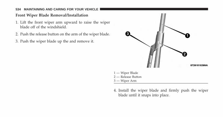
Front Wiper Blade Removal/Installation
1. Lift the front wiper arm upward to raise the wiperblade off of the windshield.
2. Push the release button on the arm of the wiper blade.
3. Push the wiper blade up the and remove it.
4. Install the wiper blade and firmly push the wiperblade until it snaps into place.
1 — Wiper Blade2 — Release Button3 — Wiper Arm
534 MAINTAINING AND CARING FOR YOUR VEHICLE

Rear Wiper Blade Removal/Installation
1. Carefully lift the rear wiper arm upward to raise thewiper blade off of the liftgate glass.
2. Grab and hold the wiper arm closest to the wiperblade end while pushing the wiper blade towards theliftgate glass to unsnap the blade pivot pin from thewiper blade holder on the wiper arm.
3. Install the wiper blade pivot pin into the wiper bladeholder at the end of the wiper arm, and firmly pushthe wiper blade until it snaps into place.
Adding Washer Fluid
The windshield washer fluid reservoir is located in theengine compartment, and the fluid level should bechecked at regular intervals. Fill the reservoir with wind-shield washer solvent (not engine coolant/ antifreeze).
Refer to “Engine Compartment” in this section for fur-ther information.
WARNING!
Commercially available windshield washer solventsare flammable. They could ignite and burn you. Caremust be exercised when filling or working aroundthe washer solution.
Exhaust System
The best protection against carbon monoxide entry intothe vehicle body is a properly maintained engine exhaustsystem.
If you notice a change in the sound of the exhaust system;or if the exhaust fumes can be detected inside the vehicle;or when the underside or rear of the vehicle is damaged;
9
MAINTAINING AND CARING FOR YOUR VEHICLE 535

have an authorized technician inspect the complete ex-haust system and adjacent body areas for broken, dam-aged, deteriorated, or mispositioned parts. Open seamsor loose connections could permit exhaust fumes to seepinto the passenger compartment. In addition, have theexhaust system inspected each time the vehicle is raisedfor lubrication or oil change. Replace as required.
WARNING!
• Exhaust gases can injure or kill. They containcarbon monoxide (CO), which is colorless andodorless. Breathing it can make you unconsciousand can eventually poison you. To avoid breathingCO, refer to “Safety Tips/Exhaust Gas” in the“Safety” section for further information.
• A hot exhaust system can start a fire if you parkover materials that can burn. Such materials might
(Continued)
WARNING! (Continued)be grass or leaves coming into contact with yourexhaust system. Do not park or operate your ve-hicle in areas where your exhaust system can con-tact anything that can burn.
CAUTION!
• The catalytic converter requires the use of un-leaded fuel only. Leaded gasoline will destroy theeffectiveness of the catalyst as an emissions controldevice and may seriously reduce engine perfor-mance and cause serious damage to the engine.
• Damage to the catalytic converter can result if yourvehicle is not kept in proper operating condition.In the event of engine malfunction, particularlyinvolving engine misfire or other apparent loss of
(Continued)
536 MAINTAINING AND CARING FOR YOUR VEHICLE

CAUTION! (Continued)performance, have your vehicle serviced promptly.Continued operation of your vehicle with a severemalfunction could cause the converter to overheat,resulting in possible damage to the converter andvehicle.
Under normal operating conditions, the catalytic con-verter will not require maintenance. However, it is im-portant to keep the engine properly tuned to assureproper catalyst operation and prevent possible catalystdamage.
NOTE: Intentional tampering with emissions controlsystems can result in civil penalties being assessedagainst you.
In unusual situations involving grossly malfunctioningengine operation, a scorching odor may suggest severeand abnormal catalyst overheating. If this occurs, stop
the vehicle, turn off the engine and allow it to cool.Service, including a tune-up to manufacturer’s specifica-tions, should be obtained immediately.
To minimize the possibility of catalytic converter dam-age:
• Do not shut off the engine or interrupt the ignition,when the transmission is in gear and the vehicle is inmotion.
• Do not try to start the engine by pushing or towing thevehicle.
• Do not idle the engine with any spark plug wiresdisconnected or removed, such as when diagnostictesting, or for prolonged periods during very roughidle or malfunctioning operating conditions. 9
MAINTAINING AND CARING FOR YOUR VEHICLE 537
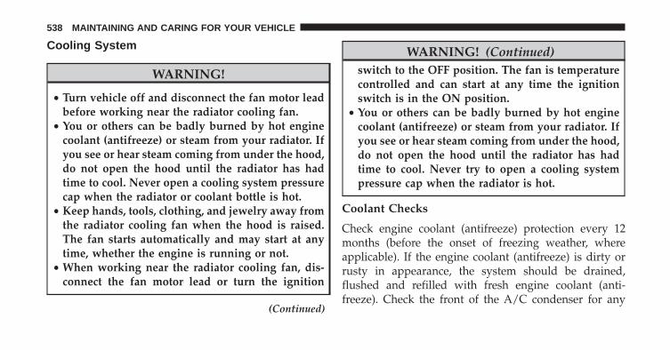
Cooling System
WARNING!
• Turn vehicle off and disconnect the fan motor leadbefore working near the radiator cooling fan.
• You or others can be badly burned by hot enginecoolant (antifreeze) or steam from your radiator. Ifyou see or hear steam coming from under the hood,do not open the hood until the radiator has hadtime to cool. Never open a cooling system pressurecap when the radiator or coolant bottle is hot.
• Keep hands, tools, clothing, and jewelry away fromthe radiator cooling fan when the hood is raised.The fan starts automatically and may start at anytime, whether the engine is running or not.
• When working near the radiator cooling fan, dis-connect the fan motor lead or turn the ignition
(Continued)
WARNING! (Continued)switch to the OFF position. The fan is temperaturecontrolled and can start at any time the ignitionswitch is in the ON position.
• You or others can be badly burned by hot enginecoolant (antifreeze) or steam from your radiator. Ifyou see or hear steam coming from under the hood,do not open the hood until the radiator has hadtime to cool. Never try to open a cooling systempressure cap when the radiator is hot.
Coolant Checks
Check engine coolant (antifreeze) protection every 12months (before the onset of freezing weather, whereapplicable). If the engine coolant (antifreeze) is dirty orrusty in appearance, the system should be drained,flushed and refilled with fresh engine coolant (anti-freeze). Check the front of the A/C condenser for any
538 MAINTAINING AND CARING FOR YOUR VEHICLE

accumulation of bugs, leaves, etc. If dirty, clean by gentlyspraying water from a garden hose vertically down theface of the condenser.
Cooling System — Drain, Flush And Refill
NOTE: Some vehicles require special tools to add coolantproperly. Failure to fill these systems properly could leadto severe internal engine damage. If any coolant isneeded to be added to the system, please contact yourlocal authorized dealer.
If the engine coolant (antifreeze) is dirty or containsvisible sediment, have an authorized dealer clean andflush with OAT coolant (antifreeze) (conforming toMS.90032).
Refer to the “Maintenance Schedule” for the propermaintenance intervals.
Selection Of Coolant
Refer to “Fluids, Lubricants, And Genuine Parts” in the“Technical Data” section for further information.
CAUTION!
• Mixing of engine coolant (antifreeze) other thanspecified Organic Additive Technology (OAT) en-gine coolant (antifreeze), may result in enginedamage and may decrease corrosion protection.Organic Additive Technology (OAT) engine cool-ant is different and should not be mixed withHybrid Organic Additive Technology (HOAT) en-gine coolant (antifreeze) or any “globally compat-ible” coolant (antifreeze). If a non-OAT enginecoolant (antifreeze) is introduced into the coolingsystem in an emergency, the cooling system willneed to be drained, flushed, and refilled with fresh
(Continued)
9
MAINTAINING AND CARING FOR YOUR VEHICLE 539

CAUTION! (Continued)OAT coolant (conforming to MS.90032), by an au-thorized dealer as soon as possible.
• Do not use water alone or alcohol-based enginecoolant (antifreeze) products. Do not use additionalrust inhibitors or antirust products, as they may notbe compatible with the engine coolant and mayplug the radiator.
• This vehicle has not been designed for use withpropylene glycol-based engine coolant (antifreeze).Use of propylene glycol-based engine coolant (an-tifreeze) is not recommended.
Adding Coolant
Your vehicle has been built with an improved enginecoolant (OAT coolant conforming to MS.90032) that al-lows extended maintenance intervals. This engine cool-ant (antifreeze) can be used up to ten years or 150,000
miles (240,000 km) before replacement. To prevent reduc-ing this extended maintenance period, it is important thatyou use the same engine coolant (OAT coolant conform-ing to MS.90032) throughout the life of your vehicle.
Please review these recommendations for using OrganicAdditive Technology (OAT) engine coolant (antifreeze)that meets the requirements of FCA Material StandardMS.90032. When adding engine coolant (antifreeze):
• We recommend using MOPAR Antifreeze/Coolant 10Year/150,000 Mile Formula OAT (Organic AdditiveTechnology) that meets the requirements of FCA Ma-terial Standard MS.90032.
• Mix a minimum solution of 50% OAT engine coolantthat meets the requirements of FCA Material StandardMS.90032 and distilled water. Use higher concentra-tions (not to exceed 70%) if temperatures below −34°F(−37°C) are anticipated. Please contact your authorizeddealer for assistance.
540 MAINTAINING AND CARING FOR YOUR VEHICLE

• Use only high purity water such as distilled or deion-ized water when mixing the water/engine coolant(antifreeze) solution. The use of lower quality waterwill reduce the amount of corrosion protection in theengine cooling system.
NOTE:
• It is the owner’s responsibility to maintain the properlevel of protection against freezing according to thetemperatures occurring in the area where the vehicle isoperated.
• Some vehicles require special tools to add coolantproperly. Failure to fill these systems properly couldlead to severe internal engine damage. If any coolant isneeded to be added to the system, please contact yourlocal authorized dealer.
• Mixing engine coolant (antifreeze) types is not recom-mended and can result in cooling system damage. If
HOAT and OAT coolant are mixed in an emergency,have a authorized dealer drain, flush, and refill withOAT coolant (conforming to MS.90032) as soon aspossible.
Cooling System Pressure Cap
The cap must be fully tightened to prevent loss of enginecoolant (antifreeze) and to ensure that engine coolant(antifreeze) will return to the radiator from the coolantrecovery tank.
The cap should be inspected and cleaned if there is anyaccumulation of foreign material on the sealing surfaces.
WARNING!
• Do not open hot engine cooling system. Never addengine coolant (antifreeze) when the engine isoverheated. Do not loosen or remove the cap to cool
(Continued)
9
MAINTAINING AND CARING FOR YOUR VEHICLE 541

WARNING! (Continued)an overheated engine. Heat causes pressure tobuild up in the cooling system. To prevent scaldingor injury, do not remove the pressure cap while thesystem is hot or under pressure.
• Do not use a pressure cap other than the onespecified for your vehicle. Personal injury or en-gine damage may result.
Disposal Of Used Engine Coolant
Used ethylene glycol-based engine coolant (antifreeze) isa regulated substance requiring proper disposal. Checkwith your local authorities to determine the disposalrules for your community. To prevent ingestion by ani-mals or children, do not store ethylene glycol-basedengine coolant in open containers or allow it to remain in
puddles on the ground. If ingested by a child or pet, seekemergency assistance immediately. Clean up any groundspills immediately.
Coolant Level
The coolant expansion bottle provides a quick visualmethod for determining that the coolant level is ad-equate. With the engine off and cold, the level of theengine coolant (antifreeze) in the bottle should be be-tween the “MIN” and “MAX” marks.
As long as the engine operating temperature is satisfac-tory, the coolant bottle need only be checked once amonth.
When additional engine coolant (antifreeze) is needed tomaintain the proper level, it should be added to thecoolant bottle. Do not overfill.
542 MAINTAINING AND CARING FOR YOUR VEHICLE

Points To Remember
NOTE: When the vehicle is stopped after a few miles/kilometers of operation, you may observe vapor comingfrom the front of the engine compartment. This is nor-mally a result of moisture from rain, snow, or highhumidity accumulating on the radiator and being vapor-ized when the thermostat opens, allowing hot enginecoolant (antifreeze) to enter the radiator.
If an examination of your engine compartment shows noevidence of radiator or hose leaks, the vehicle may besafely driven. The vapor will soon dissipate.
• Do not overfill the coolant expansion bottle.
• Check the coolant freeze point in the radiator and inthe coolant expansion bottle. If engine coolant (anti-freeze) needs to be added, the contents of the coolantexpansion bottle must also be protected against freez-ing.
• If frequent engine coolant (antifreeze) additions arerequired, the cooling system should be pressure testedfor leaks.
• Maintain engine coolant (antifreeze) concentration at aminimum of 50% OAT coolant (conforming toMS.90032) and distilled water for proper corrosionprotection of your engine which contains aluminumcomponents.
• Keep the front of the radiator clean. If your vehicle isequipped with air conditioning, keep the front of thecondenser clean.
• Do not change the thermostat for Summer or Winteroperation. If replacement is ever necessary, installONLY the correct type thermostat. Other designs mayresult in unsatisfactory engine coolant (antifreeze)performance, poor gas mileage, and increased emis-sions.
9
MAINTAINING AND CARING FOR YOUR VEHICLE 543

Brake System
In order to assure brake system performance, all brakesystem components should be inspected periodically.Refer to the “Maintenance Schedule” for the propermaintenance intervals.
WARNING!
Riding the brakes can lead to brake failure andpossibly a collision. Driving with your foot resting orriding on the brake pedal can result in abnormallyhigh brake temperatures, excessive lining wear, andpossible brake damage. Riding the brakes may alsoreduce braking capacity in an emergency.
Brake Master Cylinder
The fluid level in the master cylinder should be checkedwhen performing under hood services, or immediately ifthe “Brake Warning Light” is on.
Be sure to clean the top of the master cylinder area beforeremoving the cap. If necessary, add fluid to bring thefluid level up to the requirements described on the brakefluid reservoir. Fluid level can be expected to fall as thebrake pads wear. The brake fluid level should be checkedwhen the pads are replaced. However, low fluid levelmay be caused by a leak and a checkup may be needed.
NOTE: If your vehicle is equipped with a manualtransmission, the brake fluid reservoir supplies fluid toboth the brake system and the clutch release system. Thetwo systems are separated in the reservoir, and a leak inone system will not affect the other system. The manualtransmission clutch release system should not requirefluid replacement during the life of the vehicle. If thebrake fluid reservoir is low and the brake system doesnot indicate any leaks or other problems, it may be aresult of a leak in the hydraulic clutch release system. Seeyour local authorized dealer for service.
544 MAINTAINING AND CARING FOR YOUR VEHICLE

Use only manufacturer’s recommended brake fluid. Re-fer to “Fluids, Lubricants, And Genuine Parts” in the“Technical Data” section for further information.
WARNING!
• Use only manufacturer’s recommended brakefluid. Refer to “Fluids, Lubricants, And GenuineParts” in the “Technical Data” section for furtherinformation. Using the wrong type of brake fluidcan severely damage your brake system and/orimpair its performance. The proper type of brakefluid for your vehicle is also identified on theoriginal factory installed hydraulic master cylinderreservoir.
• To avoid contamination from foreign matter ormoisture, use only new brake fluid or fluid that hasbeen in a tightly closed container. Keep the master
(Continued)
WARNING! (Continued)cylinder reservoir cap secured at all times. Brakefluid in a open container absorbs moisture from theair resulting in a lower boiling point. This maycause it to boil unexpectedly during hard or pro-longed braking, resulting in sudden brake failure.This could result in a collision.
• Overfilling the brake fluid reservoir can result inspilling brake fluid on hot engine parts, causingthe brake fluid to catch fire. Brake fluid can alsodamage painted and vinyl surfaces, care should betaken to avoid its contact with these surfaces.
• Overfilling the brake fluid reservoir can result inspilling brake fluid on hot engine parts, causingthe brake fluid to catch fire. Brake fluid can alsodamage painted and vinyl surfaces, care should betaken to avoid its contact with these surfaces.
9
MAINTAINING AND CARING FOR YOUR VEHICLE 545

CAUTION!
Use of improper brake fluids will affect overallclutch system performance. Improper brake fluidsmay damage the clutch system resulting in loss ofclutch function and the ability to shift the transmis-sion.
Manual Transmission — If Equipped
Lubricant Selection
Use only the manufacturers recommended transmissionfluid. Refer to “Fluids, Lubricants, And Genuine Parts” in“Technical Data” for further information.
Please see your authorized dealer for service.
Fluid Level Check
Check the fluid level by removing the fill plug. The fluidlevel should be between the bottom of the fill hole and apoint not more than 3/16 inch (4.7 mm) below the bottomof the hole.
Add fluid, if necessary, to maintain the proper level.
Please see your authorized dealer for service.
Frequency Of Fluid Change
Under normal operating conditions, the fluid installed atthe factory will give satisfactory lubrication for the life ofthe vehicle. Fluid changes are not necessary unless lubri-cant has become contaminated with water.
NOTE: If contaminated with water, the fluid should bechanged immediately.
546 MAINTAINING AND CARING FOR YOUR VEHICLE

Automatic Transmission — If Equipped
Selection Of Lubricant
It is important to use the proper transmission fluid toensure optimum transmission performance and life. Useonly the manufacturer’s specified transmission fluid.Refer to “Fluids, Lubricants, And Genuine Parts” in“Technical Data” for fluid specifications. It is importantto maintain the transmission fluid at the correct levelusing the recommended fluid.
NOTE: No chemical flushes should be used in anytransmission; only the approved lubricant should beused.
CAUTION!
Using a transmission fluid other than the manufac-turer’s recommended fluid may cause deteriorationin transmission shift quality and/or torque convertershudder. Refer to “Fluids, Lubricants, And GenuineParts” in “Technical Data” for fluid specifications.
Special Additives
The manufacturer strongly recommends against usingany special additives in the transmission. AutomaticTransmission Fluid (ATF) is an engineered product andits performance may be impaired by supplemental addi-tives. Therefore, do not add any fluid additives to thetransmission. Avoid using transmission sealers as theymay adversely affect seals.
9
MAINTAINING AND CARING FOR YOUR VEHICLE 547

CAUTION!
Do not use chemical flushes in your transmission asthe chemicals can damage your transmission compo-nents. Such damage is not covered by the NewVehicle Limited Warranty.
Fluid Level Check
The fluid level is preset at the factory and does notrequire adjustment under normal operating conditions.Routine fluid level checks are not required, therefore thetransmission has no dipstick. Your authorized dealer cancheck your transmission fluid level using special servicetools. If you notice fluid leakage or transmission malfunc-tion, visit your authorized dealer immediately to havethe transmission fluid level checked. Operating the ve-hicle with an improper fluid level can cause severetransmission damage.
CAUTION!
If a transmission fluid leak occurs, visit your autho-rized dealer immediately. Severe transmission dam-age may occur. Your authorized dealer has the propertools to adjust the fluid level accurately.
Fluid And Filter Changes
Under normal operating conditions, the fluid installed atthe factory will provide satisfactory lubrication for thelife of the vehicle.
Routine fluid and filter changes are not required. How-ever, change the fluid and filter if the fluid becomescontaminated (with water, etc.), or if the transmission isdisassembled for any reason.
548 MAINTAINING AND CARING FOR YOUR VEHICLE

Appearance Care And Protection From Corrosion
Protection Of Body And Paint From Corrosion
Vehicle body care requirements vary according to geo-graphic locations and usage. Chemicals that make roadspassable in snow and ice and those that are sprayed ontrees and road surfaces during other seasons are highlycorrosive to the metal in your vehicle. Outside parking,which exposes your vehicle to airborne contaminants,road surfaces on which the vehicle is operated, extremehot or cold weather and other extreme conditions willhave an adverse effect on paint, metal trim, and under-body protection.
The following maintenance recommendations will enableyou to obtain maximum benefit from the corrosionresistance built into your vehicle.
What Causes Corrosion?
Corrosion is the result of deterioration or removal ofpaint and protective coatings from your vehicle.
The most common causes are:
• Road salt, dirt and moisture accumulation.
• Stone and gravel impact.
• Insects, tree sap and tar.
• Salt in the air near seacoast localities.
• Atmospheric fallout/industrial pollutants.
Washing
• Wash your vehicle regularly. Always wash your ve-hicle in the shade using MOPAR Car Wash, or a mildcar wash soap, and rinse the panels completely withclear water.
9
MAINTAINING AND CARING FOR YOUR VEHICLE 549

• If insects, tar, or other similar deposits have accumu-lated on your vehicle, use MOPAR Super Kleen Bugand Tar Remover to remove.
• Use a high quality cleaner wax, such as MOPARCleaner Wax to remove road film, stains and to protectyour paint finish. Take care never to scratch the paint.
• Avoid using abrasive compounds and power buffingthat may diminish the gloss or thin out the paint finish.
CAUTION!
• Do not use abrasive or strong cleaning materialssuch as steel wool or scouring powder that willscratch metal and painted surfaces.
• Use of power washers exceeding 1,200 psi (8 274kPa) can result in damage or removal of paint anddecals.
(Continued)
CAUTION! (Continued)• If the engine compartment is washed with an high
pressure jet, keep it at a distance of at least 8 inches(20 centimeters) from filler surface.
Special Care
• If you drive on salted or dusty roads or if you drivenear the ocean, hose off the undercarriage at least oncea month.
• It is important that the drain holes in the lower edgesof the doors, rocker panels, and trunk be kept clear andopen.
• If you detect any stone chips or scratches in the paint,touch them up immediately. The cost of such repairs isconsidered the responsibility of the owner.
550 MAINTAINING AND CARING FOR YOUR VEHICLE

• If your vehicle is damaged due to a collision or similarcause that destroys the paint and protective coating,have your vehicle repaired as soon as possible. Thecost of such repairs is considered the responsibility ofthe owner.
• If you carry special cargo such as chemicals, fertilizers,de-icer salt, etc., be sure that such materials are wellpackaged and sealed.
• If a lot of driving is done on gravel roads, considermud or stone shields behind each wheel.
• Use MOPAR Touch Up Paint on scratches as soon aspossible. Your authorized dealer has touch up paint tomatch the color of your vehicle.
Wheel And Wheel Trim Care
All wheels and wheel trim, especially aluminum andchrome plated wheels, should be cleaned regularly usingmild (neutral Ph) soap and water to maintain their lusterand to prevent corrosion. Wash wheels with the samesoap solution recommended for the body of the vehicle.
Your wheels are susceptible to deterioration caused bysalt, sodium chloride, magnesium chloride, calcium chlo-ride, etc., and other road chemicals used to melt ice orcontrol dust on dirt roads. Use a soft cloth or sponge andmild soap to wipe away promptly. Do not use harshchemicals or a stiff brush. They can damage the wheel’sprotective coating that helps keep them from corrodingand tarnishing.
NOTE: Many aftermarket wheel cleaners contain strongacids or strong alkaline additives that can harm the wheelsurface.
9
MAINTAINING AND CARING FOR YOUR VEHICLE 551
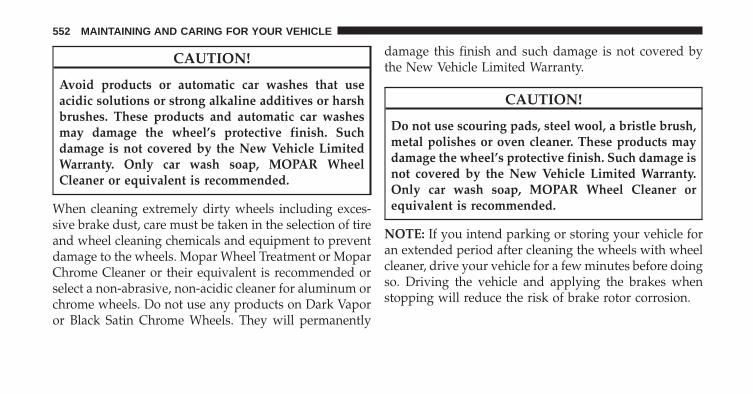
CAUTION!
Avoid products or automatic car washes that useacidic solutions or strong alkaline additives or harshbrushes. These products and automatic car washesmay damage the wheel’s protective finish. Suchdamage is not covered by the New Vehicle LimitedWarranty. Only car wash soap, MOPAR WheelCleaner or equivalent is recommended.
When cleaning extremely dirty wheels including exces-sive brake dust, care must be taken in the selection of tireand wheel cleaning chemicals and equipment to preventdamage to the wheels. Mopar Wheel Treatment or MoparChrome Cleaner or their equivalent is recommended orselect a non-abrasive, non-acidic cleaner for aluminum orchrome wheels. Do not use any products on Dark Vaporor Black Satin Chrome Wheels. They will permanently
damage this finish and such damage is not covered bythe New Vehicle Limited Warranty.
CAUTION!
Do not use scouring pads, steel wool, a bristle brush,metal polishes or oven cleaner. These products maydamage the wheel’s protective finish. Such damage isnot covered by the New Vehicle Limited Warranty.Only car wash soap, MOPAR Wheel Cleaner orequivalent is recommended.
NOTE: If you intend parking or storing your vehicle foran extended period after cleaning the wheels with wheelcleaner, drive your vehicle for a few minutes before doingso. Driving the vehicle and applying the brakes whenstopping will reduce the risk of brake rotor corrosion.
552 MAINTAINING AND CARING FOR YOUR VEHICLE

Dark Vapor Or Black Satin Chrome Wheels
CAUTION!
If your vehicle is equipped with Dark Vapor or BlackSatin Chrome wheels DO NOT USE wheel cleaners,abrasives or polishing compounds. They will perma-nently damage this finish and such damage is notcovered by the New Vehicle Limited Warranty. USEONLY MILD SOAP AND WATER WITH A SOFTCLOTH. Used on a regular basis this is all that isrequired to maintain this finish.
Stain Repel Fabric Cleaning Procedure — IfEquipped
Stain Repel seats may be cleaned in the following man-ner:
• Remove as much of the stain as possible by blottingwith a clean, dry towel.
• Blot any remaining stain with a clean, damp towel.
• For tough stains, apply MOPAR Total Clean, or a mildsoap solution to a clean, damp cloth and remove stain.Use a fresh, damp towel to remove soap residue.
• For grease stains, apply MOPAR Multi-PurposeCleaner to a clean, damp cloth and remove stain. Usea fresh, damp towel to remove soap residue.
• Do not use any harsh solvents or any other form ofprotectants on Stain Repel products.
Interior Care
Use MOPAR Total Clean to clean fabric upholstery andcarpeting.
Use MOPAR Total Clean to clean vinyl upholstery.
MOPAR Total Clean is specifically recommended forleather upholstery.
9
MAINTAINING AND CARING FOR YOUR VEHICLE 553

Your leather upholstery can be best preserved by regularcleaning with a damp soft cloth. Small particles of dirtcan act as an abrasive and damage the leather upholsteryand should be removed promptly with a damp cloth.Stubborn soils can be removed easily with a soft clothand MOPAR Total Clean. Care should be taken to avoidsoaking your leather upholstery with any liquid. Pleasedo not use polishes, oils, cleaning fluids, solvents, deter-gents, or ammonia-based cleaners to clean your leatherupholstery. Application of a leather conditioner is notrequired to maintain the original condition.
WARNING!
Do not use volatile solvents for cleaning purposes.Many are potentially flammable, and if used inclosed areas they may cause respiratory harm.
CAUTION!
Direct contact of air fresheners, insect repellents,suntan lotions, or hand sanitizers to the plastic,painted, or decorated surfaces of the interior maycause permanent damage. Wipe away immediately.
CAUTION!
Damage caused by these type of products may not becovered by your New Vehicle Limited Warranty.
CAUTION!
Do not use Alcohol and Alcohol-based and/or Ketonbased cleaning products to clean leather seats, asdamage to the seat may result.
554 MAINTAINING AND CARING FOR YOUR VEHICLE

Cleaning Headlights
Your vehicle has plastic headlights that are lighter andless susceptible to stone breakage than glass headlights.
Plastic is not as scratch resistant as glass and thereforedifferent lens cleaning procedures must be followed.
To minimize the possibility of scratching the lenses andreducing light output, avoid wiping with a dry cloth. Toremove road dirt, wash with a mild soap solution fol-lowed by rinsing.
Do not use abrasive cleaning components, solvents, steelwool or other aggressive material to clean the lenses.
Glass Surfaces
All glass surfaces should be cleaned on a regular basiswith MOPAR Glass Cleaner, or any commercialhousehold-type glass cleaner. Never use an abrasive typecleaner. Use caution when cleaning the inside rear win-dow equipped with electric defrosters or windowsequipped with radio antennas. Do not use scrapers orother sharp instrument that may scratch the elements.
When cleaning the rear view mirror, spray cleaner on thetowel or cloth that you are using. Do not spray cleanerdirectly on the mirror.
Instrument Panel Cover
The instrument panel cover has a low glare surface whichminimizes reflections on the windshield. Do not useprotectants or other products which may cause undesir-able reflections. Use soap and warm water to restore thelow glare surface.
9
MAINTAINING AND CARING FOR YOUR VEHICLE 555

Instrument Panel Bezels
CAUTION!
When installing hanging air fresheners in your ve-hicle, read the installation instructions carefully.Some air fresheners will damage the finish ofpainted or decorated parts if allowed to directlycontact any surface.
Cleaning Plastic Instrument Cluster Lenses
The lenses in front of the instruments in this vehicle aremolded in clear plastic. When cleaning the lenses, caremust be taken to avoid scratching the plastic.
1. Clean with a wet soft cloth. A mild soap solution maybe used, but do not use high alcohol content orabrasive cleaners. If soap is used, wipe clean with aclean damp cloth.
2. Dry with a soft cloth.
Seat Belt Maintenance
Do not bleach, dye or clean the belts with chemicalsolvents or abrasive cleaners. This will weaken the fabric.Sun damage can also weaken the fabric.
If the belts need cleaning, use a mild soap solution orlukewarm water. Do not remove the belts from thevehicle to wash them. Dry with a soft cloth.
Replace the belts if they appear frayed or worn or if thebuckles do not work properly.
NOTE: If the belts retract slowly, inspect the upperturning loop for soiling. If soiling is present, clean with awet soft cloth until all residue is removed.
556 MAINTAINING AND CARING FOR YOUR VEHICLE

WARNING!
A frayed or torn belt could rip apart in a collision andleave you with no protection. Inspect the belt systemperiodically, checking for cuts, frays, or loose parts.Damaged parts must be replaced immediately. Donot disassemble or modify the system. Seat beltassemblies must be replaced after a collision if theyhave been damaged (i.e., bent retractor, torn web-bing, etc.).
LIFTING A VEHICLE
In the case where it is necessary to lift the vehicle, go toa your authorized dealer or service station.
The lifting points on the vehicle are marked on side skirtswith symbols ( see example shown).
9
MAINTAINING AND CARING FOR YOUR VEHICLE 557

Lifting Point Locations
558 MAINTAINING AND CARING FOR YOUR VEHICLE

TIRE SAFETY INFORMATION
Tire Markings
NOTE:
• P (Passenger) — Metric tire sizing is based on U.S.design standards. P-Metric tires have the letter “P”molded into the sidewall preceding the size designa-tion. Example: P215/65R15 95H.
• European — Metric tire sizing is based on Europeandesign standards. Tires designed to this standard havethe tire size molded into the sidewall beginning withthe section width. The letter �P� is absent from this tiresize designation. Example: 215/65R15 96H.
1 — U.S. DOT Safety StandardsCode (TIN)
4 — Maximum Load
2 — Size Designation 5 — Maximum Pressure3 — Service Description 6 — Treadwear, Traction and
Temperature Grades
9
MAINTAINING AND CARING FOR YOUR VEHICLE 559

• LT (Light Truck) — Metric tire sizing is based on U.S.design standards. The size designation for LT-Metrictires is the same as for P-Metric tires except for theletters “LT” that are molded into the sidewall preced-ing the size designation. Example: LT235/85R16.
• Temporary spare tires are designed for temporaryemergency use only. Temporary high pressure com-pact spare tires have the letter “T” or “S” molded intothe sidewall preceding the size designation. Example:T145/80D18 103M.
• High flotation tire sizing is based on U.S. designstandards and it begins with the tire diameter moldedinto the sidewall. Example: 31x10.5 R15 LT.
560 MAINTAINING AND CARING FOR YOUR VEHICLE

Tire Sizing Chart
EXAMPLE:Example Size Designation: P215/65R15XL 95H, 215/65R15 96H, LT235/85R16C, T145/80D18 103M, 31x10.5 R15 LT
P = Passenger car tire size based on U.S. design standards, or�....blank....� = Passenger car tire based on European design standards, orLT = Light truck tire based on U.S. design standards, orT or S = Temporary spare tire or31 = Overall diameter in inches (in)215, 235, 145 = Section width in millimeters (mm)65, 85, 80 = Aspect ratio in percent (%)
– Ratio of section height to section width of tire, or10.5 = Section width in inches (in)R = Construction code
– �R� means radial construction, or– �D� means diagonal or bias construction
15, 16, 18 = Rim diameter in inches (in)
9
MAINTAINING AND CARING FOR YOUR VEHICLE 561

EXAMPLE:Service Description:
95 = Load Index– A numerical code associated with the maximum load a tire can carry
H = Speed Symbol– A symbol indicating the range of speeds at which a tire can carry a load corresponding toits load index under certain operating conditions– The maximum speed corresponding to the speed symbol should only be achieved underspecified operating conditions (i.e., tire pressure, vehicle loading, road conditions, andposted speed limits)
Load Identification:Absence of the following load identification symbols on the sidewall of the tire indicates a Standard Load (SL) tire:• XL = Extra load (or reinforced) tire, or• LL = Light load tire or• C, D, E, F, G = Load range associated with the maximum load a tire can carry at a specified pressureMaximum Load – Maximum load indicates the maximum load this tire is designed to carryMaximum Pressure – Maximum pressure indicates the maximum permissible cold tire inflation pressure for this tire
562 MAINTAINING AND CARING FOR YOUR VEHICLE

Tire Identification Number (TIN)
The TIN may be found on one or both sides of the tire,however, the date code may only be on one side. Tireswith white sidewalls will have the full TIN, including thedate code, located on the white sidewall side of the tire.
Look for the TIN on the outboard side of black sidewalltires as mounted on the vehicle. If the TIN is not found onthe outboard side, then you will find it on the inboardside of the tire.
EXAMPLE:DOT MA L9 ABCD 0301
DOT = Department of Transportation– This symbol certifies that the tire is in compliance with the U.S. Department of Transportation tiresafety standards and is approved for highway use
MA = Code representing the tire manufacturing location (two digits)L9 = Code representing the tire size (two digits)ABCD = Code used by the tire manufacturer (one to four digits)03 = Number representing the week in which the tire was manufactured (two digits)
– 03 means the 3rd week
9
MAINTAINING AND CARING FOR YOUR VEHICLE 563

EXAMPLE:DOT MA L9 ABCD 0301
01 = Number representing the year in which the tire was manufactured (two digits)– 01 means the year 2001– Prior to July 2000, tire manufacturers were only required to have one number to represent the yearin which the tire was manufactured. Example: 031 could represent the 3rd week of 1981 or 1991
564 MAINTAINING AND CARING FOR YOUR VEHICLE

Tire Terminology And Definitions
Term DefinitionB-Pillar The vehicle B-Pillar is the structural member of the body located
behind the front door.Cold Tire Inflation Pressure Cold tire inflation pressure is defined as the tire pressure after
the vehicle has not been driven for at least three hours, or drivenless than 1 mile (1.6 km) after sitting for a minimum of threehours. Inflation pressure is measured in units of PSI (pounds persquare inch) or kPa (kilopascals).
Maximum Inflation Pressure The maximum inflation pressure is the maximum permissiblecold tire inflation pressure for this tire. The maximum inflationpressure is molded into the sidewall.
Recommended Cold Tire Inflation Pres-sure
Vehicle manufacturer’s recommended cold tire inflation pressureas shown on the tire placard.
Tire Placard A label permanently attached to the vehicle describing the vehi-cle’s loading capacity, the original equipment tire sizes and therecommended cold tire inflation pressures.
9
MAINTAINING AND CARING FOR YOUR VEHICLE 565

Tire Loading And Tire Pressure
Tire And Loading Information Placard Location
NOTE: The proper cold tire inflation pressure is listed onthe driver’s side B-Pillar or the rear edge of the driver’sside door.
Example Tire Placard Location (Door)
Example Tire Placard Location (B-Pillar)
566 MAINTAINING AND CARING FOR YOUR VEHICLE

Tire And Loading Information Placard
This placard tells you important information about the:
1. Number of people that can be carried in the vehicle.
2. Total weight your vehicle can carry.
3. Tire size designed for your vehicle.
4. Cold tire inflation pressures for the front, rear, andspare tires.
Loading
The vehicle maximum load on the tire must not exceedthe load carrying capacity of the tire on your vehicle. Youwill not exceed the tire’s load carrying capacity if youadhere to the loading conditions, tire size, and cold tireinflation pressures specified on the Tire and LoadingInformation placard in “Vehicle Loading” in the “StartingAnd Operating” section of this manual.
NOTE: Under a maximum loaded vehicle condition,gross axle weight ratings (GAWRs) for the front and rearaxles must not be exceeded. For further information onGAWRs, vehicle loading, and trailer towing, refer to“Vehicle Loading” in the “Starting And Operating” sec-tion of this manual.
Tire And Loading Information Placard 9
MAINTAINING AND CARING FOR YOUR VEHICLE 567

To determine the maximum loading conditions of yourvehicle, locate the statement “The combined weight ofoccupants and cargo should never exceed XXX kg orXXX lbs” on the Tire and Loading Information placard.The combined weight of occupants, cargo/luggage andtrailer tongue weight (if applicable) should never exceedthe weight referenced here.
Steps For Determining Correct Load Limit—
(1) Locate the statement “The combined weight ofoccupants and cargo should never exceed XXX kg orXXX lbs.” on your vehicle’s placard.
(2) Determine the combined weight of the driver andpassengers that will be riding in your vehicle.
(3) Subtract the combined weight of the driver andpassengers from XXX kg or XXX lbs.
(4) The resulting figure equals the available amount ofcargo and luggage load capacity. For example, if“XXX” amount equals 1400 lbs. and there will be five150 lb passengers in your vehicle, the amount ofavailable cargo and luggage load capacity is 650 lbs.(1400-750 (5x150) = 650 lbs.)
(5) Determine the combined weight of luggage andcargo being loaded on the vehicle. That weight maynot safely exceed the available cargo and luggage loadcapacity calculated in Step 4.
(6) If your vehicle will be towing a trailer, load fromyour trailer will be transferred to your vehicle. Con-sult this manual to determine how this reduces theavailable cargo and luggage load capacity of yourvehicle.
568 MAINTAINING AND CARING FOR YOUR VEHICLE

Metric Example For Load Limit
For example, if “XXX” amount equals 635 kg, and therewill be five 68 kg passengers in your vehicle, the amountof available cargo and luggage load capacity is 295 kg(635-340 (5x68) = 295 kg) as shown in step 4.
NOTE:
• If your vehicle will be towing a trailer, load from yourtrailer will be transferred to your vehicle. The follow-ing table shows examples on how to calculate totalload, cargo/luggage, and towing capacities of yourvehicle with varying seating configurations and num-ber and size of occupants. This table is for illustrationpurposes only and may not be accurate for the seatingand load carry capacity of your vehicle.
• For the following example, the combined weight ofoccupants and cargo should never exceed 865 lbs(392 kg).
9
MAINTAINING AND CARING FOR YOUR VEHICLE 569
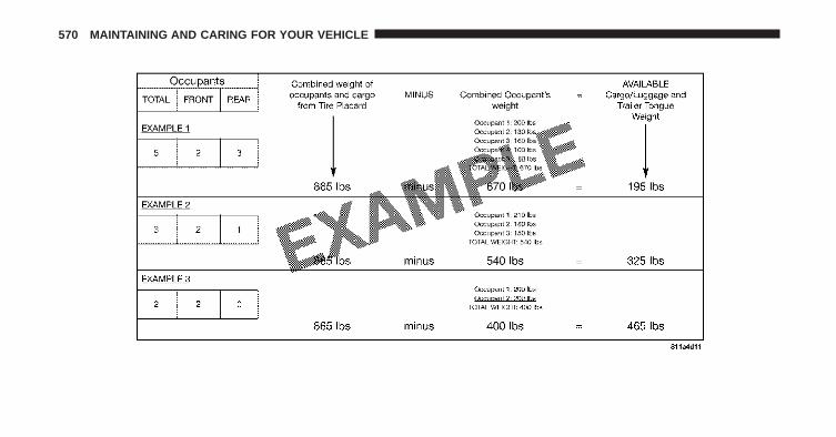
570 MAINTAINING AND CARING FOR YOUR VEHICLE

WARNING!
Overloading of your tires is dangerous. Overloadingcan cause tire failure, affect vehicle handling, andincrease your stopping distance. Use tires of therecommended load capacity for your vehicle. Neveroverload them.
TIRES — GENERAL INFORMATION
Tire Pressure
Proper tire inflation pressure is essential to the safe andsatisfactory operation of your vehicle. Four primary areasare affected by improper tire pressure:• Safety and Vehicle Stability
• Economy
• Tread Wear
• Ride Comfort
Safety
WARNING!
• Improperly inflated tires are dangerous and cancause collisions.
• Underinflation increases tire flexing and can resultin overheating and tire failure.
• Overinflation reduces a tire’s ability to cushionshock. Objects on the road and chuckholes cancause damage that result in tire failure.
• Overinflated or underinflated tires can affect ve-hicle handling and can fail suddenly, resulting inloss of vehicle control.
• Unequal tire pressures can cause steering prob-lems. You could lose control of your vehicle.
• Unequal tire pressures from one side of the vehicleto the other can cause the vehicle to drift to theright or left.
(Continued)
9
MAINTAINING AND CARING FOR YOUR VEHICLE 571

WARNING! (Continued)• Always drive with each tire inflated to the recom-
mended cold tire inflation pressure.
Both under-inflation and over-inflation affect the stabilityof the vehicle and can produce a feeling of sluggishresponse or over responsiveness in the steering.
NOTE:
• Unequal tire pressures from side to side may causeerratic and unpredictable steering response.
• Unequal tire pressure from side to side may cause thevehicle to drift left or right.
Fuel Economy
Underinflated tires will increase tire rolling resistanceresulting in higher fuel consumption.
Tread Wear
Improper cold tire inflation pressures can cause abnor-mal wear patterns and reduced tread life, resulting in theneed for earlier tire replacement.
Ride Comfort And Vehicle Stability
Proper tire inflation contributes to a comfortable ride.Over-inflation produces a jarring and uncomfortable ride.
Tire Inflation Pressures
The proper cold tire inflation pressure is listed on thedriver’s side B-Pillar or rear edge of the driver’s side door.
At least once a month:
• Check and adjust tire pressure with a good qualitypocket-type pressure gauge. Do not make a visualjudgement when determining proper inflation. Tiresmay look properly inflated even when they are under-inflated.
572 MAINTAINING AND CARING FOR YOUR VEHICLE
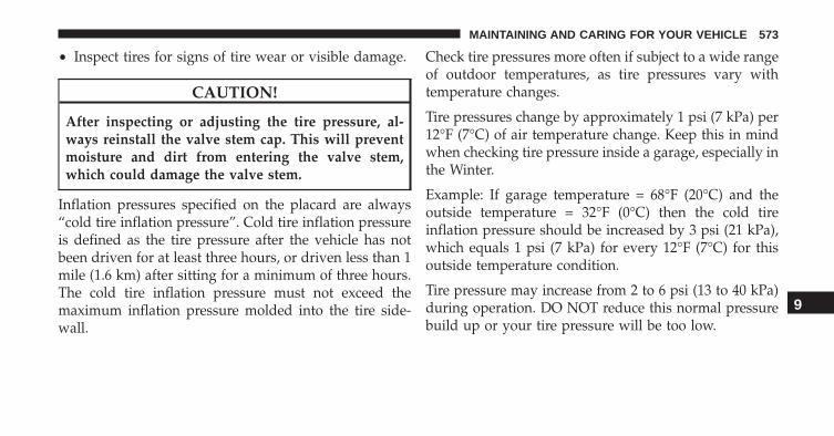
• Inspect tires for signs of tire wear or visible damage.
CAUTION!
After inspecting or adjusting the tire pressure, al-ways reinstall the valve stem cap. This will preventmoisture and dirt from entering the valve stem,which could damage the valve stem.
Inflation pressures specified on the placard are always“cold tire inflation pressure”. Cold tire inflation pressureis defined as the tire pressure after the vehicle has notbeen driven for at least three hours, or driven less than 1mile (1.6 km) after sitting for a minimum of three hours.The cold tire inflation pressure must not exceed themaximum inflation pressure molded into the tire side-wall.
Check tire pressures more often if subject to a wide rangeof outdoor temperatures, as tire pressures vary withtemperature changes.
Tire pressures change by approximately 1 psi (7 kPa) per12°F (7°C) of air temperature change. Keep this in mindwhen checking tire pressure inside a garage, especially inthe Winter.
Example: If garage temperature = 68°F (20°C) and theoutside temperature = 32°F (0°C) then the cold tireinflation pressure should be increased by 3 psi (21 kPa),which equals 1 psi (7 kPa) for every 12°F (7°C) for thisoutside temperature condition.
Tire pressure may increase from 2 to 6 psi (13 to 40 kPa)during operation. DO NOT reduce this normal pressurebuild up or your tire pressure will be too low.
9
MAINTAINING AND CARING FOR YOUR VEHICLE 573

Tire Pressures For High Speed Operation
The manufacturer advocates driving at safe speeds andwithin posted speed limits. Where speed limits or condi-tions are such that the vehicle can be driven at highspeeds, maintaining correct tire inflation pressure is veryimportant. Increased tire pressure and reduced vehicleloading may be required for high-speed vehicle opera-tion. Refer to your authorized tire dealer or originalequipment vehicle dealer for recommended safe operat-ing speeds, loading and cold tire inflation pressures.
WARNING!
High speed driving with your vehicle under maxi-mum load is dangerous. The added strain on yourtires could cause them to fail. You could have aserious collision. Do not drive a vehicle loaded to themaximum capacity at continuous speeds above75 mph (120 km/h).
Radial Ply Tires
WARNING!
Combining radial ply tires with other types of tireson your vehicle will cause your vehicle to handlepoorly. The instability could cause a collision. Al-ways use radial ply tires in sets of four. Nevercombine them with other types of tires.
Tire RepairIf your tire becomes damaged, it may be repaired if itmeets the following criteria:• The tire has not been driven on when flat.
• The damage is only on the tread section of your tire(sidewall damage is not repairable).
• The puncture is no greater than a ¼ of an inch (6 mm).
Consult an authorized tire dealer for tire repairs andadditional information.
574 MAINTAINING AND CARING FOR YOUR VEHICLE

Damaged Run Flat tires, or Run Flat tires that haveexperienced a loss of pressure should be replaced imme-diately with another Run Flat tire of identical size andservice description (Load Index and Speed Symbol).
Tire Types
All Season Tires — If Equipped
All Season tires provide traction for all seasons (Spring,Summer, Fall and Winter). Traction levels may varybetween different all season tires. All season tires can beidentified by the M+S, M&S, M/S or MS designation onthe tire sidewall. Use all season tires only in sets of four;failure to do so may adversely affect the safety andhandling of your vehicle.
Summer Or Three Season Tires — If Equipped
Summer tires provide traction in both wet and dryconditions, and are not intended to be driven in snow oron ice. If your vehicle is equipped with Summer tires, be
aware these tires are not designed for Winter or colddriving conditions. Install Winter tires on your vehiclewhen ambient temperatures are less than 40°F (5°C) or ifroads are covered with ice or snow. For more informa-tion, contact an authorized dealer.
Summer tires do not contain the all season designation ormountain/snowflake symbol on the tire sidewall. UseSummer tires only in sets of four; failure to do so mayadversely affect the safety and handling of your vehicle.
WARNING!
Do not use Summer tires in snow/ice conditions. Youcould lose vehicle control, resulting in severe injuryor death. Driving too fast for conditions also createsthe possibility of loss of vehicle control.
9
MAINTAINING AND CARING FOR YOUR VEHICLE 575

Snow Tires
Some areas of the country require the use of snow tiresduring the Winter. Snow tires can be identified by a“mountain/snowflake” symbol on the tire sidewall.
If you need snow tires, select tiresequivalent in size and type to theoriginal equipment tires. Use snowtires only in sets of four; failure to doso may adversely affect the safety andhandling of your vehicle.
Snow tires generally have lower speed ratings than whatwas originally equipped with your vehicle and shouldnot be operated at sustained speeds over 75 mph(120 km/h). For speeds above 75 mph (120 km/h), referto original equipment or an authorized tire dealer forrecommended safe operating speeds, loading and coldtire inflation pressures.
While studded tires improve performance on ice, skidand traction capability on wet or dry surfaces may bepoorer than that of non-studded tires. Some states pro-hibit studded tires; therefore, local laws should bechecked before using these tire types.
Run Flat Tires — If Equipped
Run Flat tires allow you the capability to drive 50 miles(80 km) at 50 mph (80 km/h) after a rapid loss of inflationpressure. This rapid loss of inflation is referred to as theRun Flat mode. A Run Flat mode occurs when the tireinflation pressure is of/or below 14 psi (96 kPa). Once aRun Flat tire reaches the run flat mode it has limiteddriving capabilities and needs to be replaced immedi-ately. A Run Flat tire is not repairable.
It is not recommended driving a vehicle loaded at fullcapacity or to tow a trailer while a tire is in the run flatmode.
576 MAINTAINING AND CARING FOR YOUR VEHICLE

See the tire pressure monitoring section for more infor-mation.
Spare Tires — If Equipped
NOTE: For vehicles equipped with Tire Service Kitinstead of a spare tire, please refer to “Tire Service Kit” in“In Case Of Emergency” for further information.
CAUTION!
Because of the reduced ground clearance, do not takeyour vehicle through an automatic car wash with acompact or limited-use temporary spare installed.Damage to the vehicle may result.
Tire Spinning
When stuck in mud, sand, snow, or ice conditions, do notspin your vehicle’s wheels above 30 mph (48 km/h) orfor longer than 30 seconds continuously without stop-ping.
Refer to “Freeing A Stuck Vehicle” in “In Case OfEmergency” for further information.
WARNING!
Fast spinning tires can be dangerous. Forces gener-ated by excessive wheel speeds may cause tire dam-age or failure. A tire could explode and injure some-one. Do not spin your vehicle’s wheels faster than30 mph (48 km/h) for more than 30 seconds continu-ously when you are stuck, and do not let anyone neara spinning wheel, no matter what the speed.
9
MAINTAINING AND CARING FOR YOUR VEHICLE 577

Tread Wear Indicators
Tread wear indicators are in the original equipment tiresto help you in determining when your tires should bereplaced.
These indicators are molded into the bottom of the treadgrooves. They will appear as bands when the tread depthbecomes a 1/16 of an inch (1.6 mm). When the tread isworn to the tread wear indicators, the tire should bereplaced. Refer to “Replacement Tires” in this section forfurther information.
Life Of Tire
The service life of a tire is dependent upon varyingfactors including, but not limited to:
• Driving style.
• Tire pressure - Improper cold tire inflation pressurescan cause uneven wear patterns to develop across thetire tread. These abnormal wear patterns will reducetread life, resulting in the need for earlier tire replace-ment.
• Distance driven.
Tire Tread
1 — Worn Tire2 — New Tire
578 MAINTAINING AND CARING FOR YOUR VEHICLE

• Performance tires, tires with a speed rating of V orhigher, and Summer tires typically have a reducedtread life. Rotation of these tires per the vehicle main-tenance schedule is highly recommended.
WARNING!
Tires and the spare tire should be replaced after sixyears, regardless of the remaining tread. Failure tofollow this warning can result in sudden tire failure.You could lose control and have a collision resultingin serious injury or death.
Keep dismounted tires in a cool, dry place with as littleexposure to light as possible. Protect tires from contactwith oil, grease, and gasoline.
Replacement Tires
The tires on your new vehicle provide a balance of manycharacteristics. They should be inspected regularly forwear and correct cold tire inflation pressures. The manu-facturer strongly recommends that you use tires equiva-lent to the originals in size, quality and performancewhen replacement is needed. Refer to the paragraph on“Tread Wear Indicator”. Refer to the Tire and LoadingInformation placard or the Vehicle Certification Label forthe size designation of your tire. The Load Index andSpeed Symbol for your tire will be found on the originalequipment tire sidewall. See the Tire Sizing Chart ex-ample found in the “Tire Safety Information” section ofthis manual for more information relating to the LoadIndex and Speed Symbol of a tire. 9
MAINTAINING AND CARING FOR YOUR VEHICLE 579

It is recommended to replace the two front tires or tworear tires as a pair. Replacing just one tire can seriouslyaffect your vehicle’s handling. If you ever replace awheel, make sure that the wheel’s specifications matchthose of the original wheels.
It is recommended you contact your authorized tiredealer or original equipment dealer with any questionsyou may have on tire specifications or capability. Failureto use equivalent replacement tires may adversely affectthe safety, handling, and ride of your vehicle.
WARNING!
• Do not use a tire, wheel size or rating other thanthat specified for your vehicle. Some combinationsof unapproved tires and wheels may change sus-pension dimensions and performance characteris-tics, resulting in changes to steering, handling, and
(Continued)
WARNING! (Continued)braking of your vehicle. This can cause unpredict-able handling and stress to steering and suspen-sion components. You could lose control and havea collision resulting in serious injury or death. Useonly the tire and wheel sizes with load ratingsapproved for your vehicle.
• Never use a tire with a smaller load index orcapacity, other than what was originally equippedon your vehicle. Using a tire with a smaller loadindex could result in tire overloading and failure.You could lose control and have a collision.
• Failure to equip your vehicle with tires havingadequate speed capability can result in sudden tirefailure and loss of vehicle control.
580 MAINTAINING AND CARING FOR YOUR VEHICLE

CAUTION!
Replacing original tires with tires of a different sizemay result in false speedometer and odometer read-ings.
TIRE CHAINS (TRACTION DEVICES)
Use of traction devices require sufficient tire-to-bodyclearance. Follow these recommendations to guardagainst damage.
• Traction device must be of proper size for the tire, asrecommended by the traction device manufacturer.
• Install on front tires only
• Due to limited clearance, the following traction de-vices are recommended:
All Models:
• The use of 7mm tire chains is permitted with the use of215/60R16 only. Front tires ONLY.
• Original Equipment 215/60R17, 215/65R17 and 225/55R18 tire sizes are NOT chainable.
CAUTION!
• Use on front tires ONLY.• Damage may result if tire chains or traction devices
are used with original equipment size tires.
WARNING!
Using tires of different size and type (M+S, Snow)between front and rear axles can cause unpredictablehandling. You could lose control and have a collision.
9
MAINTAINING AND CARING FOR YOUR VEHICLE 581

CAUTION!
To avoid damage to your vehicle or tires, observe thefollowing precautions:• Because of restricted traction device clearance be-
tween tires and other suspension components, it isimportant that only traction devices in good condi-tion are used. Broken devices can cause seriousdamage. Stop the vehicle immediately if noiseoccurs that could indicate device breakage. Removethe damaged parts of the device before further use.
• Install device as tightly as possible and then re-tighten after driving about ½ mile (0.8 km).
• Do not exceed 30 mph (48 km/h).• Drive cautiously and avoid severe turns and large
bumps, especially with a loaded vehicle.• Do not drive for a prolonged period on dry pave-
ment.
(Continued)
CAUTION! (Continued)• Observe the traction device manufacturer’s instruc-
tions on the method of installation, operatingspeed, and conditions for use. Always use thesuggested operating speed of the device manufac-turer’s if it is less than 30 mph (48 km/h).
• Do not use traction devices on a compact spare tire.
TIRE ROTATION RECOMMENDATIONS
The tires on the front and rear of your vehicle operate atdifferent loads and perform different steering, handling,and braking functions. For these reasons, they wear atunequal rates.
These effects can be reduced by timely rotation of tires.The benefits of rotation are especially worthwhile withaggressive tread designs such as those on On/Off Road
582 MAINTAINING AND CARING FOR YOUR VEHICLE

type tires. Rotation will increase tread life, help to main-tain mud, snow, and wet traction levels, and contribute toa smooth, quiet ride.
Refer to the “Maintenance Schedule” for the propermaintenance intervals. The reasons for any rapid orunusual wear should be corrected prior to rotation beingperformed.
The suggested Front Wheel Drive (FWD) rotationmethod is the “forward cross” shown in the followingdiagram. This rotation pattern does not apply to somedirectional tires that must not be reversed.
Front Wheel Drive (FWD) Tire Rotation
9
MAINTAINING AND CARING FOR YOUR VEHICLE 583

The suggested Four Wheel Drive (4WD) Tire rotationmethod is the “rearward cross” shown in the followingdiagram.
CAUTION!
Proper operation of four-wheel drive vehicles de-pends on tires of equal size, type and circumferenceon each wheel. Any difference in tire size can causedamage to the power transfer unit. Tire rotationschedule should be followed to balance tire wear.
STORING THE VEHICLE
If the vehicle should remain stationary for more than amonth, observe the following precautions:
• Park your vehicle in a covered, dry and possibly airylocation the windows open slightly;
• Check that the Electric Park Brake is not engaged.
• Disconnect the negative (-) terminal from the batterypost and be sure that the battery is fully charged.During storage check battery charge quarterly.
Four Wheel Drive (4WD) Tire Rotation
584 MAINTAINING AND CARING FOR YOUR VEHICLE

• If you do not disconnect the battery from the electricalsystem, check the battery charge every thirty days.
• Clean and protect the painted parts by applying pro-tective waxes.
• Clean and protect polished metal parts by applyingprotective waxes.
• Apply talcum powder to the front and rear wiperblades and leave raised from the glass.
• Cover the vehicle with an appropriate cover takingcare not to damage the painted surface by draggingacross dirty surfaces. Do not use plastic sheeting whichwill not allow the evaporation of moisture present onthe surface of the vehicle.
• Inflate the tires at a pressure of +7.25 psi (+0.5 bar)higher than recommended on the tire placard andcheck it periodically.
• Do not drain the engine cooling system.
• Whenever you leave the vehicle is stationary for twoweeks or more, idle the engine for approximately fiveminutes with the air conditioning system on and highfan speed. This will ensure a proper lubrication of thesystem, thus minimizing the possibility of damage tothe compressor when the vehicle is put back intooperation.
NOTE: When the vehicle has not been started or drivenfor at least 30 days, an Extended Park Start Procedure isrequired to start the vehicle. Refer to “Starting TheEngine” in “Starting And Operating” for further infor-mation.
9
MAINTAINING AND CARING FOR YOUR VEHICLE 585

CAUTION!
Before removal of the positive and negative termi-nals to the battery, wait at least a minute withignition switch in the OFF position and close thedrivers door. When reconnecting the positive andnegative terminals to the battery be sure the ignitionswitch is in the OFF position and the drivers door isclosed.
586 MAINTAINING AND CARING FOR YOUR VEHICLE

TECHNICAL DATA
CONTENTS� VEHICLE IDENTIFICATION . . . . . . . . . . . . . . .588
▫ Chassis Number . . . . . . . . . . . . . . . . . . . . . .588
� WHEEL AND TIRE TORQUESPECIFICATIONS . . . . . . . . . . . . . . . . . . . . . .589
▫ Torque Specifications . . . . . . . . . . . . . . . . . . .589
� FLUID CAPACITIES . . . . . . . . . . . . . . . . . . . .592
� FLUIDS, LUBRICANTS, AND GENUINEPARTS . . . . . . . . . . . . . . . . . . . . . . . . . . . . . .593
▫ Engine . . . . . . . . . . . . . . . . . . . . . . . . . . . . .593
▫ Chassis . . . . . . . . . . . . . . . . . . . . . . . . . . . .594
10

VEHICLE IDENTIFICATION
Chassis Number
The chassis number (VIN) is stamped on a plate locatedon the left front corner of the instrument panel cover,which is visible from outside the car through the wind-shield.
Vehicle Identification Number (VIN)
588 TECHNICAL DATA

This number is also stamped on the floor of the passengercompartment, near the right front seat.
A. Cover
WHEEL AND TIRE TORQUE SPECIFICATIONS
Proper lug nut/bolt torque is very important to ensurethat the wheel is properly mounted to the vehicle. Anytime a wheel has been removed and reinstalled on thevehicle the lug nuts/bolts should be torqued using aproperly calibrated torque wrench.
Torque Specifications
Lug Nut/Bolt Torque **Lug Nut/Bolt Size
Lug Nut/Bolt Socket
Size89 Ft-Lbs (120 N·m) M12 x 1.25 17 mm
**Use only your Authorized Dealer recommended lugnuts/bolts and clean or remove any dirt or oil beforetightening.
Vehicle Identification Number (VIN) 10
TECHNICAL DATA 589

Inspect the wheel mounting surface prior to mountingthe tire and remove any corrosion or loose particles.
Tighten the lug nuts/bolts in a star pattern until eachnut/bolt has been tightened twice.
Wheel Mounting Surface Torque Patterns
590 TECHNICAL DATA

After 25 miles (40 km) check the lug nut/bolt torque to besure that all the lug nuts/bolts are properly seatedagainst the wheel.
WARNING!
To avoid the risk of forcing the vehicle off the jack,do not tighten the lug nuts fully until the vehicle hasbeen lowered. Failure to follow this warning mayresult in personal injury.
10
TECHNICAL DATA 591

FLUID CAPACITIES
U.S MetricFuel (Approximate)1.4L Turbo/2.4L Engine 12.7 Gallons 48 LitersEngine Oil With Filter1.4L Turbo Engine (SAE 5W-40 Synthetic, API Certified) 4.0 Quarts 3.8 Liters2.4L Engine (SAE 0W-20, API Certified) 5.5 Quarts 5.2 LitersCooling System *1.4L Turbo Engine (MOPAR Antifreeze/Engine Coolant10 Year/150,000 Mile Formula)
5.5 Quarts 5.2 Liters
2.4L Engine (MOPAR Antifreeze/Engine Coolant 10 Year/150,000 Mile Formula)
6.8 Quarts 6.5 Liters
* Includes heater and coolant recovery bottle filled to MAX level.
592 TECHNICAL DATA

FLUIDS, LUBRICANTS, AND GENUINE PARTS
Engine
Component Fluid, Lubricant, or Genuine PartEngine Coolant We recommend you use MOPAR Antifreeze/Coolant 10 Year/150,000 Mile For-
mula OAT (Organic Additive Technology) or equivalent meeting the requirementsof FCA Material Standard MS.90032.
Engine Oil – 1.4L TurboEngine
We recommend you use SAE 5W-40 API Certified Synthetic Engine Oil, meeting therequirements of FCA Material Standard MS-12991 such as MOPAR, Pennzoil, andShell Helix. Refer to your engine oil filler cap for correct SAE grade.
Engine Oil – 2.4L Engine We recommend you use SAE 0W-20 API Certified Engine Oil, meeting therequirements of FCA Material Standard MS-6395 such as MOPAR, Pennzoil, andShell Helix. Refer to your engine oil filler cap for correct SAE grade.
Engine Oil Filter We recommend you use a MOPAR Engine Oil Filter.Spark Plugs We recommend you use MOPAR Spark Plugs.Fuel Selection –1.4L Turbo Engine
91 Octane Recommended, 87 Octane Acceptable, 0-15% Ethanol
Fuel Selection – 2.4L Engine 87 Octane, 0-15% Ethanol
10
TECHNICAL DATA 593

Chassis
Component Fluid, Lubricant, or Genuine PartManual Transmission – If Equipped We recommend you use MOPAR C Series Manual &
Dual Dry Clutch Transmission Fluid.Automatic Transmission – If Equipped Use only MOPAR ZF 8&9 Speed ATF Automatic Trans-
mission Fluid, or equivalent. Failure to use the correctfluid may affect the function or performance of yourtransmission.
Power Transfer Unit (PTU) – If Equipped We recommended you use MOPAR Front Axle/PTUSynthetic Axle Lubricant SAE 75W-90 (API GL-5).
Rear Differential (RDM) – If Equipped We recommended you use MOPAR Rear Axle/RDMSynthetic Axle Lubricant SAE 75W-90 (API GL-5).
Brake Master Cylinder We recommend you use MOPAR DOT 4. If DOT 4 brakefluid is not available, then DOT 3 is acceptable.DOT 4 brake fluid must be changed every 2 yearregardless of mileage.
594 TECHNICAL DATA

MULTIMEDIA
CONTENTS� CYBERSECURITY. . . . . . . . . . . . . . . . . . . . . . .597
� UCONNECT SETTINGS . . . . . . . . . . . . . . . . . .598
▫ Buttons On The Faceplate. . . . . . . . . . . . . . . .600
▫ Buttons On The Touchscreen. . . . . . . . . . . . . .600
▫ Customer Programmable Features —Uconnect 5.0 Settings . . . . . . . . . . . . . . . . . .600
▫ Customer Programmable Features —Uconnect 6.5AN Settings . . . . . . . . . . . . . . . .616
� UCONNECT RADIOS . . . . . . . . . . . . . . . . . . .631
� USB/MEDIA PLAYER CONTROL —IF EQUIPPED . . . . . . . . . . . . . . . . . . . . . . . . .632
� STEERING WHEEL AUDIO CONTROLS . . . . . .633
▫ Radio Operation . . . . . . . . . . . . . . . . . . . . . .634
▫ Media Mode . . . . . . . . . . . . . . . . . . . . . . . . .634
� RADIO OPERATION AND MOBILE DEVICES . .635
▫ Regulatory And Safety Information . . . . . . . . .635
� VOICE RECOGNITION QUICK TIPS . . . . . . . .637
▫ Introducing Uconnect. . . . . . . . . . . . . . . . . . .637
▫ Get Started . . . . . . . . . . . . . . . . . . . . . . . . . .638
▫ Basic Voice Commands. . . . . . . . . . . . . . . . . .639
▫ Radio . . . . . . . . . . . . . . . . . . . . . . . . . . . . . .64111

▫ Media. . . . . . . . . . . . . . . . . . . . . . . . . . . . . .643
▫ Phone. . . . . . . . . . . . . . . . . . . . . . . . . . . . . .644
▫ Voice Text Reply . . . . . . . . . . . . . . . . . . . . . .646
▫ Navigation (6.5AN) . . . . . . . . . . . . . . . . . . . .647
▫ Uconnect Access* (6.5A/6.5AN) . . . . . . . . . . .648
▫ Registration (6.5A/6.5AN) . . . . . . . . . . . . . . .649
▫ Mobile App (6.5AN) . . . . . . . . . . . . . . . . . . .650
▫ Voice Texting (6.5AN) . . . . . . . . . . . . . . . . . .650
▫ Yelp (6.5AN) . . . . . . . . . . . . . . . . . . . . . . . . .651
▫ SiriusXM Travel Link (6.5AN) . . . . . . . . . . . . .652
▫ General Information. . . . . . . . . . . . . . . . . . . .653
▫ Additional Information . . . . . . . . . . . . . . . . .654
596 MULTIMEDIA

CYBERSECURITY
Your vehicle may be a connected vehicle and may beequipped with both wired and wireless networks. Thesenetworks allow your vehicle to send and receive infor-mation. This information allows systems and features inyour vehicle to function properly.
Your vehicle may be equipped with certain securityfeatures to reduce the risk of unauthorized and unlawfulaccess to vehicle systems and wireless communications.Vehicle software technology continues to evolve overtime and FCA US LLC, working with its suppliers,evaluates and takes appropriate steps as needed. Similarto a computer or other devices, your vehicle may requiresoftware updates to improve the usability and perfor-mance of your systems or to reduce the potential risk ofunauthorized and unlawful access to your vehicle sys-tems.
The risk of unauthorized and unlawful access to yourvehicle systems may still exist, even if the most recentversion of vehicle software (such as Uconnect software) isinstalled.
WARNING!
• It is not possible to know or to predict all of thepossible outcomes if your vehicle’s systems arebreached. It may be possible that vehicle systems,including safety related systems, could be im-paired or a loss of vehicle control could occur thatmay result in an accident involving serious injuryor death.
(Continued)
11
MULTIMEDIA 597

WARNING! (Continued)• ONLY insert media (e.g., USB, SD card, or CD) into
your vehicle if it came from a trusted source. Mediaof unknown origin could possibly contain mali-cious software, and if installed in your vehicle, itmay increase the possibility for vehicle systems tobe breached.
• As always, if you experience unusual vehicle be-havior, take your vehicle to your nearest authorizeddealer immediately.
NOTE:
• FCA or your dealer may contact you directly regardingsoftware updates.
• To help further improve vehicle security and minimizethe potential risk of a security breach, vehicle ownersshould:
• Routinely check www.driveuconnect.com/software-update to learn about available Uconnect softwareupdates.
• Only connect and use trusted media devices (e.g.personal mobile phones, USBs, CDs).
Privacy of any wireless and wired communications can-not be assured. Third parties may unlawfully interceptinformation and private communications without yourconsent. For further information, refer to “Onboard Di-agnostic System (OBD II) Cybersecurity” in “Getting ToKnow Your Instrument Panel”.
UCONNECT SETTINGS
The Uconnect system uses a combination of buttons onthe touchscreen and buttons on the faceplate located onthe center of the instrument panel that allow you toaccess and change the customer programmable features.Many features can vary by vehicle.
598 MULTIMEDIA

Uconnect 5.0 Buttons On The Touchscreen And ButtonsOn The Faceplate
1 — Uconnect Buttons On The Touchscreen2 — Uconnect Buttons On The Faceplate
Uconnect 6.5AN Buttons On The Touchscreen AndButtons On The Faceplate
1 — Uconnect Buttons On The Touchscreen2 — Uconnect Buttons On The Faceplate
11
MULTIMEDIA 599

Buttons On The Faceplate
Buttons on the faceplate are located below, and beside theUconnect system in the center of the instrument panel. Inaddition, there is a Scroll/Enter control knob located onthe right side. Turn the control knob to scroll throughmenus and change settings (i.e., 30, 60, 90), push thecenter of the control knob one or more times to select orchange a setting (i.e., ON, OFF).
Your Uconnect system may also have Display Off andback arrow buttons on the faceplate.
Push the Display Off button on the faceplate to turn offthe Uconnect screen. Push the Display Off button on thefaceplate a second time to turn the screen on.
Push the Back Arrow button on the faceplate to exit outof a Menu or certain option on the Uconnect system.
Buttons On The Touchscreen
Buttons on the touchscreen are accessible on theUconnect touchscreen.
Customer Programmable Features — Uconnect5.0 Settings
Push the MORE button on the faceplate, then press the“Settings” button on the touchscreen to display thesettings menu screen. In this mode the Uconnect systemallows you to access programmable features that may beequipped such as Display, Clock, Safety/Assistance,Lights, Doors & Locks, Engine Off Options, CompassSettings, Audio, Phone/Bluetooth, Radio Setup, RestoreSettings and Clear Personal Data.NOTE: Only one touchscreen area may be selected at atime.
When making a selection, press the button on the touch-screen to enter the desired mode. Once in the desiredmode, press and release the preferred setting and make
600 MULTIMEDIA

your selection. Once the setting is complete, either pressthe Back Arrow button on the touchscreen or the Backbutton on the faceplate to return to the previous menu orpress the “X” button on the touchscreen to close out ofthe settings screen. Pressing the Up or Down Arrowbuttons on the right side of the screen will allow you totoggle up or down through the available settings.
NOTE: All settings should be changed with the ignitionin the “MAR/RUN” position.
Display
After pressing the “Display” button on the touchscreenthe following settings will be available.
• Display Mode
When in this display you may select the “Auto” or“Manual” display settings. To change Mode status, pressand release the “Auto” or “Manual” button on thetouchscreen.
• Brightness
When in this display, you may select the overall screenbrightness with the headlights on or off. Adjust thebrightness with the “+” and “–” setting buttons on thetouchscreen or by selecting any point on the scale be-tween the “+” and “–” buttons on the touchscreen.
• Language
When in this display, you may select one of multiplelanguages (English/Español/Français) for all display no-menclature, including the trip functions and the naviga-tion system (if equipped). Press the “Language” buttonon the touchscreen, then press the desired languagebutton on the touchscreen.
11
MULTIMEDIA 601

• Touchscreen Beep
When in this display, you may turn on or shut off thesound heard when a touchscreen button is pressed. Pressthe “Touchscreen Beep” button on the touchscreen until acheck-mark appears next to the setting, showing thatsetting has been selected.
Units
After pressing the “Units” button on the touchscreen youmay select each unit of measure independently displayedin the Electronic Vehicle Information System (EVIC) orDriver Information Display (DID). The following select-able units of measure are listed below:
• US
Changes the EVIC/DID to US units of measure.
• Metric
Changes the EVIC/DID to Metric units of measure.
• Custom• Distance
Select from: “mi” or “km.”• Fuel Consumption
Select from: “MPG” (US), “MPG” (UK), “L/100 km”or “km/L.”
• PressureSelect from: “psi,” “kPa,” or “bar.”
• TemperatureSelect from: “°C,” or “°F.”
Clock & Date
After pressing the “Clock & Date” button on the touch-screen the following settings will be available:
• Set Time & Format
When in this display, you may set the time and formatmanually. Press the “Set Time & Format” button then
602 MULTIMEDIA

choose from a 12 hour or 24 hour format. Press thecorresponding arrow above and below the current timeto adjust, then select “AM” or “PM.”
• Show Time Status
When in this display, you may turn on or shut off thedigital clock in the status bar. To change the Show TimeStatus setting press the “Show Time Status” button on thetouchscreen and select from “ON” or “OFF.”
• Set Date
When in this display, you may set the date manually.Press the “Set Date” button on the touchscreen then pressthe corresponding arrows above and below the currentdate to adjust.
• Sync Time — If Equipped
When in this display, you may sync the time with GPS.Press the “Sync Time” button on the touchscreen andselect from “ON” or “OFF.”
Safety/Assistance
After pressing the “Safety/Assistance” button on thetouchscreen the following settings will be available:
• ParkView Backup Camera — If Equipped
When the vehicle is shifted out of REVERSE (with cameradelay turned OFF), the rear camera mode is exited andthe navigation or audio screen appears again. When thevehicle is shifted out of REVERSE (with camera delayturned ON), the rear view image with dynamic grid lineswill be displayed for up to 10 seconds after shifting out of“REVERSE” unless the forward vehicle speed exceeds8 mph (13 km/h), the transmission is shifted into PARKor the ignition is switched to the OFF position.• ParkView Backup Camera On/Off — If Equipped
To change the setting, press the “On” or “Off” buttonuntil it is highlighted.
11
MULTIMEDIA 603
• ParkView Backup Camera Delay — If EquippedPress the “Parkview Backup camera Delay” buttonon the touchscreen to turn the ParkView Delay ON orOFF.
• ParkView Backup Camera Active Guide Lines — IfEquipped
When this feature is enabled, active (dynamic) gridlines are overlaid on the Rear Backup Camera imageto illustrate the width of the vehicle and its projectedback up path based on the steering wheel position. Adashed center line overlay indicates the center of thevehicle to assist with parking or aligning to a hitch/receiver.
• ParkView Backup Camera Fixed Guide Lines — IfEquipped
When this feature is enabled, fixed (static) grid linesare overlaid on the Rear Backup Camera image toillustrate the width of the vehicle.
• Forward Collision Warning-Plus (FCW+) — If Equipped
The Front Collision Warning (FCW+) feature can be canbe set to Far, or set to Near. The default status of FCW+is the Far setting. This means the system will warn you ofa possible collision with the vehicle in front of you whenyou are farther away. This gives you the most reactiontime. To change the setting for a more dynamic drivingexperience, select the Near setting. This warns you of apossible collision when you are much closer to thevehicle in front of you. To change the FCW+ status, pressand release the “Near” or “Far” button.• Forward Collision Warning-Plus (FCW+) ActiveBraking — If Equipped
The FCW+ system includes Advanced Brake Assist(ABA). When this feature is selected, it will apply thebrakes to slow your vehicle in case of potentialforward collision. The ABA applies additional brakepressure when the driver requests insufficient brake
604 MULTIMEDIA

pressure to avoid a potential frontal collision. TheABA system becomes active at 5 mph (8 km/h).
• ParkSense — If Equipped
The ParkSense system will scan for objects behind thevehicle when the transmission gear selector is in RE-VERSE and the vehicle speed is less than 11 mph(18 km/h). It will provide an alert (audible and/orvisual) to indicate the proximity to other objects. Thesystem can be enabled with Sound Only, or Sound andDisplay. To change the ParkSense status, press and re-lease the “Sound Only” or “Sounds and Display” button.Refer to “ParkSense” in “Starting And Operating” forsystem function and operating information.• Rear ParkSense Volume — If Equipped
Rear Park Assist chime volume settings can be se-lected from the EVIC/DID or Uconnect System (if
equipped). The chime volume settings include“LOW,” “MEDIUM,” and “HIGH.” The factory de-fault volume setting is MEDIUM.
• Front ParkSense Volume — If EquippedFront Park Assist chime volume settings can beselected from the EVIC/DID or Uconnect System (ifequipped). The chime volume settings include“LOW,” “MEDIUM,” and “HIGH.” The factory de-fault volume setting is MEDIUM.
• Rear ParkSense Braking Assist — If EquippedWhen this feature is selected, the park assist systemwill detect objects located behind the vehicle andutilize autonomous braking to stop the vehicle.Refer to “ParkSense Rear Park Assist” in “Startingand Operating” for system function and operatinginformation.
11
MULTIMEDIA 605

• LaneSense Warning — If Equipped
When this feature is selected, it sets the distance at whichthe steering wheel will provide feedback for potentiallane departures. The LDW sensitivity can be set toprovide either an “early,” “medium,” or “late” warningzone start point.
• LaneSense Strength — If Equipped
When this feature is selected, it sets the strength of thesteering wheel feedback for potential lane departures.The amount of directional torque the steering system canapply to the steering wheel to correct for vehicle lanedeparture can be set at “Low,” “Medium” or “High.”
• Blind Spot Alert — If Equipped
When this feature is selected, the Blind Spot Alert featurecan be set to Off, Lights or Lights and Chime. The BlindSpot Alert feature can be activated in Lights mode. Whenthis mode is selected, the Blind Spot Monitor (BSM)
system is activated and will only show a visual alert inthe outside mirrors. When Lights & Chime mode isactivated, the Blind Spot Monitor (BSM) will show avisual alert in the outside mirrors as well as an audiblealert when the turn signal is on. When Off is selected, theBlind Spot Monitor (BSM) system is deactivated. Tochange the Blind Spot Alert status, press the “Off,”“Lights” or “Lights & Chime” button on the touchscreen.Then press the back arrow button on the touchscreen.
NOTE: If your vehicle has experienced any damage inthe area where the sensor is located, even if the fascia isnot damaged, the sensor may have become misaligned.Take your vehicle to an authorized dealer to verify sensoralignment. A sensor that is misaligned will result in theBSM not operating to specification.
606 MULTIMEDIA

• Electric Park Brake Service Mode
This feature provides a means for a technician or vehicleowner to utilize a vehicle integrated, menu driven sys-tem, to command the electric park brake retraction, toservice the rear foundation brakes (brake pads, calipers,rotors, etc.).
Lights
After pressing the “Lights” button on the touchscreen thefollowing settings will be available.
• Headlight Sensitivity
When this feature is selected, it allows the HeadlightSensitivity to be adjusted according to three levels:
Level 1 = minimum sensitivity
Level 2 = medium sensitivity
Level 3 = maximum sensitivity
NOTE: The greater the sensitivity set, the less the exter-nal light variation required to turn on the lights (e.g. witha setting on level 3 at sunset the headlights turn on earlierthan in levels 1 and 2). To change the Headlight Sensi-tivity setting, press the “1,” “2” or “3” button on thetouchscreen to select your desired Headlight Sensitivitylevel.
• Headlight Off Delay
When this feature is selected, it allows the adjustment ofthe amount of time the headlights remain on after theengine is shut off. To change the Headlights Off Delaysetting, press the Headlights Off Delay button on thetouchscreen, and choose either 0 sec, 30 sec, 60 sec or 90seconds. The selected button will highlight indicatingthat the setting has been selected.
11
MULTIMEDIA 607

• Greeting Lights
When this feature is selected, it allows the greeting lightsto be turned On or Off. To change the Greeting Lightssetting, press the “On” or “Off” button on the touch-screen to select your desired Greeting Light setting.
• Automatic High Beam Headlamps — If Equipped
When this feature is selected, the high beam headlightswill activate/deactivate automatically under certain con-ditions. To make your selection, press the “Auto HighBeams” button on the touchscreen, then select from “On”or “Off.”
• Daytime Running Lights
When this feature is selected, the headlights will turn onwhile the engine is running. To make your selection,press the “Daytime Running Lights” button on the touch-screen, then choose “Yes” or “No.” The button willhighlight indicating that the setting has been selected.
• Cornering Lights
When this feature is selected, if the steering wheelrotation angle is large or the turn signal indicators are on,a light (incorporated in the fog light) will turn on, on therelevant side to improve visibility at night. To change theCornering Lights setting, press the “On” or “Off” buttonon the touchscreen to select your desired CorneringLights setting.
• Flash Lights With Lock — If Equipped
When this feature is selected, the exterior lights will flashwhen the doors are locked or unlocked with the key fob.This feature may be selected with or without the SoundHorn on Lock feature selected. To make your selection,press the “Flash Lights w/Lock” button on the touch-screen, then choose “On” or “Off.”
608 MULTIMEDIA
Doors & Locks
After pressing the “Doors & Locks” button on the touch-screen the following settings will be available.
• Auto Door Locks
When this feature is selected, all doors will lock auto-matically when the vehicle reaches a speed of 12 mph(20 km/h). To make your selection, press the “Auto DoorLocks” button on the touchscreen and select from “On”or “Off.”
• Auto Unlock On Exit
When this feature is selected, all doors will unlock whenthe vehicle is stopped and the transmission is in thePARK or NEUTRAL position and the driver’s door isopened. To make your selection, press the “Auto Unlockon Exit” button on the touchscreen and select from “On”or “Off.”
• Flash Lights With Lock
When this feature is selected, the exterior lights will flashwhen the doors are locked or unlocked with the key fobor the Passive Entry Feature. To make your selection,press the “Flash Lights w/Lock” button on the touch-screen and select from “On” or “Off.”
• Horn With Lock
When this feature is selected, the horn will sound whenthe key fob lock button is pressed. To make your selec-tion, press the “Horn w/Lock” button on the touchscreenand select from �Off,” “1st Press,” or “2nd Press”
• Horn With Remote Start — If Equipped
Press the “Horn w/Remote Start” button on the touch-screen to change this display. When this feature is se-lected, the horn will sound when the remote start isactivated. To make your selection, press the “Sound HornWith Remote Start” button on the touchscreen and select“ON” or “OFF.”
11
MULTIMEDIA 609

• Passive Entry
This feature allows you to lock and unlock the vehicle’sdoor(s) without having to press the key fob lock orunlock buttons. To make your selection, press the “Pas-sive Entry” button on the touchscreen and select from“On” or “Off. Refer to “Keyless Enter-N-Go” in “GettingTo Know Your Vehicle” for further information.
• Remote Door Unlock/Door Unlock
When “Driver” is selected, only the driver’s door willunlock on the first push of the key fob UNLOCK button,you must push the key fob UNLOCK button twice tounlock the passenger’s doors. When “All” is selected, allof the doors will unlock on the first press of the key fobUNLOCK button.
NOTE: If “All” is programmed, all doors will unlock nomatter which Passive Entry equipped door handle isgrasped. If “Driver” is programmed, only the driver’s
door will unlock when the driver’s door is grasped.Touching the handle more than once will only result inthe driver’s door opening once. If the driver door isopened, the interior door lock/unlock switch can be usedto unlock all doors (or use key fob).
Engine Off Options
After pressing the “Engine Off Options” button on thetouchscreen the following settings will be available.
• Engine Off Power Delay — If Equipped
When this feature is selected, the power windowswitches, radio, Uconnect phone system (if equipped),DVD video system (if equipped), power sunroof (ifequipped), and power outlets will remain active for up to10 minutes after the ignition is cycled to OFF. Openingeither front door will cancel this feature. To change theEngine Off Power Delay status press the “0 seconds,” “45seconds,” “5 minutes” or “10 minutes” button on thetouchscreen.
610 MULTIMEDIA

• Headlight Off Delay
When this feature is selected, the driver can choose tohave the headlights remain on for 0, 30, 60, or 90 secondswhen exiting the vehicle. To change the Headlight OffDelay status press the “+” or “–” button on the touch-screen to select your desired time interval.
• Radio Off Delay
When this feature is selected, the radio will stay on for apreset time after the ignition key is turned to STOP/OFF.To change the Radio Off Delay status, press the “0 MIN”or “20 MIN” button on the touchscreen to select yourdesired time interval.
Compass Settings — If Equipped
After pressing the “Compass Settings” button on thetouchscreen the following settings will be available:
NOTE: Before compass calibration is performed, thecompass variance zone should be set for best results.
• Compass Variance
Press “Compass Variance” on the touchscreen to changethis setting. You will then be able to select a compassvariance of 1 through 15 per the compass variance zonemap figure.
Compass Variance is the difference between MagneticNorth and Geographic North. To compensate for thedifferences the variance should be set for the zone wherethe vehicle is being driven, illustrated in the zone map.Once properly set, the compass will automatically com-pensate for the differences when calibrated, and providethe most accurate compass headings.
11
MULTIMEDIA 611

• Compass Calibration
Press “Compass Calibration” on the touchscreen to entercalibration. To start calibration of the compass, press the“YES” button on the touchscreen and complete one ormore 360-degree turns (in an area free from large metal or
metallic objects). A message will appear on the touch-screen when the compass has been successfully cali-brated.
NOTE: Keep magnetic materials away from the top of theinstrument panel, such as Mobile Phones, Laptops andRadar Detectors. This is where the compass module islocated, and it can cause interference with the compasssensor, and it may give false readings.
Audio
After pressing the “Audio” button on the touchscreen thefollowing settings will be available:
• Equalizer
When in this display you may adjust the Bass, Mid andTreble settings. Adjust the settings with the “+” and “–”setting buttons on the touchscreen or by selecting anypoint on the scale between the “+” and “–” buttons on thetouchscreen.
Compass Variance Zone Map
612 MULTIMEDIA

NOTE: Bass/Mid/Treble allow you to simply slide yourfinger up or down to change the setting as well as pressdirectly on the desired setting.
• Balance/Fade
When in this display you may adjust the Balance andFade settings.
• Speed Adjusted Volume
This feature increases or decreases volume relative tovehicle speed. To change the Speed Adjusted Volumepress the “Off,” “1,” “2” or “3” button on the touchscreen.
• Surround Sound — If Equipped
This feature provides simulated surround sound mode.To make your selection, press the “Surround Sound”button on the touchscreen, select “On” or “Off”.
• Loudness — If Equipped
Loudness improves sound quality at lower volumes. Tomake your selection, press the “Loudness” button on thetouchscreen, then choose “Yes” or “No.” The button willhighlight indicating that the setting has been selected.
• AUX Volume Offset — If Equipped
This feature provides the ability to tune the audio levelfor portable devices connected through the AUX input.To make your selection, press the “AUX Volume Offset”button on the touchscreen, select “On” or “Off”.
• Auto-On Radio
The Radio automatically turns on when vehicle is in runor will recall whether it was on or off at last ignition off.To make your selection, press the “Loudness” button onthe touchscreen, select “On,” “Off” or “Recall Last”.
11
MULTIMEDIA 613

Phone/Bluetooth
After pressing the “Phone/Bluetooth” button on thetouchscreen the following settings will be available:
• Paired Phones
This feature shows which phones are paired to thePhone/Bluetooth system. For further information, referto the Uconnect Supplement Manual.
SiriusXM Setup — If Equipped
After pressing the “SiriusXM Setup” button on the touch-screen, the following settings will be available:
• Channel Skip
SiriusXM can be programmed to designate a group ofchannels that are the most desirable to listen to or toexclude undesirable channels while scanning. To makeyour selection, press the “Channel Skip” button on thetouchscreen, select the channels you would like to skip.
• Subscription Information
New vehicle purchasers or lessees will receive a freelimited time subscription to SiriusXM Satellite Radiowith your radio. Following the expiration of the freeservices, it will be necessary to access the information onthe Subscription Information screen to re-subscribe.
Press the “Subscription Info” button on the touchscreento access the Subscription Information screen.
Write down the SIRIUS ID numbers for your receiver. Toreactivate your service, either call the number listed onthe screen or visit the provider online.
NOTE: SiriusXM Travel Link is a separate subscriptionand is available for U.S. residents only.
614 MULTIMEDIA

Restore Settings
After pressing the “Restore Settings” button on thetouchscreen the following settings will be available:
• Restore Settings
When this feature is selected it will reset all settings totheir default settings. To restore the settings to theirdefault setting, press the “Restore Settings” button. Apop-up will appear asking �Are you sure you want toreset your settings to default?” select “OK” to restore,“Cancel” or “X” to exit without making changes. Oncethe settings are restored, a pop up appears stating�Settings reset to default.�
Clear Personal Data
After pressing the “Clear Personal Data Settings” buttonon the touchscreen the following settings will be avail-able:
• Clear Personal Data
When this feature is selected it will remove all personaldata including Bluetooth devices and presets. To removepersonal information, press the “Clear Personal Data”button and a pop-up will appear asking �Are you sureyou want to clear all personal data?” select “OK” to clear,“Cancel” or “X” to exit without making changes. Oncethe data has been cleared, a pop up appears stating�Personal data cleared”.
11
MULTIMEDIA 615

Customer Programmable Features — Uconnect6.5AN Settings
Press the Settings button to display the menu settingscreen. In this mode the Uconnect system allows you toaccess programmable features that may be equippedsuch as Display, Clock, Safety & Driving Assistance,Lights, Doors & Locks, engine Off Options, Audio,Phone/Bluetooth, SiriusXM Setup, Restore Settings De-faults, Clear Personal Data and System Information.
NOTE:
• Only one touchscreen area may be selected at a time.
• Depending on the vehicles options, feature settingsmay vary.
When making a selection, press the button on the touch-screen to enter the desired mode. Once in the desiredmode, press and release the preferred setting and makeyour selection. Once the setting is complete, either press
the Back Arrow button on the touchscreen to return to theprevious menu, or press the “X” button on the touch-screen to close out of the settings screen. Pressing the Upor Down Arrow button on the right side of the screen willallow you to toggle up or down through the availablesettings.
Display
After pressing the “Display” button on the touchscreenthe following settings will be available:
• Display Mode
This feature will allow you to select one of the autodisplay settings. To change Mode status, press and re-lease the “Auto” or “Manual” button on the touchscreen.
NOTE: When Day or Night is selected for the DisplayMode, the usage of the Parade Mode feature will causethe radio to activate the Display Brightness Day controleven though the headlights are on.
616 MULTIMEDIA

• Display Brightness With Headlights ON
This feature will allow you to select the brightness withthe headlights on. Adjust the brightness with the “+” and“–” setting buttons on the touchscreen or by selecting anypoint on the scale between the “+” and “–” buttons on thetouchscreen.
• Display Brightness With Headlights OFF
When in this display, you may select the brightness withthe headlights off. Adjust the brightness with the “+” and“–” setting buttons on the touchscreen or by selecting anypoint on the scale between the “+” and “–” buttons on thetouchscreen.
• Set Language
When in this display, you may select one of multiplelanguages (English/Español/Français) for all display no-menclature, including the trip functions and the naviga-tion system (if equipped). Press the Set Language buttonon the touchscreen, then press the desired languagebutton on the touchscreen.
• Touchscreen Beep
When in this display, you may turn on or shut off thesound heard when a touchscreen button (button on thetouchscreen) is pressed. Press the “Touchscreen Beep”button on the touchscreen. Press the “On” or “Off”button on the touchscreen to turn the Touchscreen BeepON or OFF.
11
MULTIMEDIA 617

Units
• Units
When in this display, you may select to have the Elec-tronic Vehicle Information System (EVIC) or Driver In-formation Display (DID), odometer, and navigation sys-tem (if equipped) changed between US and Metric unitsof measure. Press “US,” “Metric” or “Custom.”
• Custom
When “Custom” is selected, you may select each unit ofmeasure independently displayed in the DID, and navi-gation system. The following selectable units of measureare listed below:
Distance — Select from: “MI” or “KM.”
Fuel Consumption — Select from: “MPG” (US), “MPG”(UK), L/100 km, or km/L.
Tire Pressure — Select from: “psi”, “kPa”, or “bar.”
Temperature — Select from: “°F” or “°C.”
Voice
After pressing the “Voice” button on the touchscreen thefollowing settings will be available:
• Voice Response Length
When in this display, you may change the Voice Re-sponse Length settings. To change the Voice ResponseLength, press the “Voice Response Length” button on thetouchscreen and select from “Brief” or “Detailed.”
• Show Command List
When in this display, you may change the Show Com-mand List settings. To change the Show Command Listsettings, press the “Show Command List” button on thetouchscreen and select from “Always,” “With Help” or“Never.”
618 MULTIMEDIA

Clock
After pressing the “Clock” button on the touchscreen thefollowing settings will be available:
• Show Time In Status Bar
This feature will allow you to turn on or shut off thedigital clock in the status bar. To change the Show TimeStatus setting press the “On” or “Off” button on thetouchscreen.
• Sync Time With GPS
This feature will allow you to automatically have theradio set the time. To change the Sync Time setting, pressthe “Sync Time with GPS” button on the touchscreenthen select from “On” or “Off.” When “On” is selectedyou can only set the day, month and year. If �Off� isselected you can set hour, minutes, format, show time instatus bar, day, month, and year.
• Set Day
This feature will allow you to set the day. To make yourselection, press the “–” or “+” buttons on the touchscreento adjust the day up or down.
• Set Month
This feature will allow you to set the month. To makeyour selection, press the “–” or “+” buttons on thetouchscreen to adjust the month up or down.
• Set Year
This feature will allow you to set the year. To make yourselection, press the “–” or “+” buttons on the touchscreento adjust the year up or down.
• Set Hours
This feature will allow you to adjust the hours. The SyncTime with GPS “On” button must not be selected. Tomake your selection, press the “–” or “+” buttons on thetouchscreen to adjust the hours up or down.
11
MULTIMEDIA 619
• Set Minutes
This feature will allow you to adjust the minutes. TheSync Time with GPS “On” button must not be selected.To make your selection, press the “–” or “+” buttons onthe touchscreen to adjust the minutes up or down.
• Time Format
This feature will allow you to select the time format displaysetting. Press the “Time Format” button on the touchscreen.Press the “12hrs” or “24hrs” button on the touchscreen.
Safety & Driving Assistance
After pressing the “Safety & Driving Assistance” button onthe touchscreen the following settings will be available:
• Forward Collision Warning-Plus (FCW+) — IfEquipped
The Front Collision Warning (FCW+) feature can be canbe set to Far, or Near. The default status of FCW+ is the
Far setting. This means the system will warn you of apossible collision with the vehicle in front of you whenyou are farther away. This gives you the most reactiontime. To change the setting for a more dynamic drivingexperience, select the Near setting. This warns you of apossible collision when you are much closer to thevehicle in front of you. To change the FCW+ status, pressthe “Fwd Collision Warning” button and select the“Near” or “Far” button.
• Forward Collision Warning-Plus (FCW+) ActiveBraking — If Equipped
The FCW+ system includes Advanced Brake Assist(ABA). When this feature is selected, it will apply thebrakes to slow your vehicle in case of potential forwardcollision. The ABA applies additional brake pressurewhen the driver requests insufficient brake pressure toavoid a potential frontal collision. The ABA system
620 MULTIMEDIA

becomes active at 5 mph (8 km/h). To change the ActiveBraking status, press the “Active Braking” button andselect the “On” or “Off” button.
• LaneSense Warning — If Equipped
When this feature is selected, it sets the distance at whichthe steering wheel will provide feedback for potentiallane departures. The LDW sensitivity can be set toprovide either an “early,” “medium,” or “late” warningzone start point. To change the LaneSense Warningstatus, press the “LaneSense Warning” button and selectfrom the “Early,” “Med,” or “Late” buttons.
• LaneSense Strength — If Equipped
When this feature is selected, it sets the strength of thesteering wheel feedback for potential lane departures.The amount of directional torque the steering system canapply to the steering wheel to correct for vehicle lanedeparture can be set at “Low,” “Med” or “High.” To
change the LaneSense Strength status, Press the “La-neSense Strength” button and select from the “Low,”“Medium” or “High” buttons.
• ParkSense — If Equipped
The ParkSense system will scan for objects behind thevehicle when the transmission gear selector is in RE-VERSE and the vehicle speed is less than 11 mph(18 km/h). It will provide an alert (audible and/orvisual) to indicate the proximity to other objects. Thesystem can be enabled with Sound Only, or Sound andDisplay. To change the ParkSense status, press and re-lease the “Off,” “Sound Only,” or “Sound & Display”button. Refer to “ParkSense” in “Starting And Operat-ing” for system function and operating information.
Refer to “ParkSense Rear Park Assist” in “Starting AndOperating” for system function and operating informa-tion. 11
MULTIMEDIA 621

• Front ParkSense Volume — If Equipped
Front Park Assist chime volume settings can be selectedfrom the EVIC or Uconnect System (if equipped). Thechime volume settings include “LOW,” “MEDIUM,” and“HIGH.” The factory default volume setting is MEDIUM.
• Blind Spot Alert — If Equipped
When this feature is selected, the Blind Spot Alert featurecan be set to Off, Lights or Lights and Chime. The BlindSpot Alert feature can be activated in Lights mode. Whenthis mode is selected, the Blind Spot Monitor (BSM)system is activated and will only show a visual alert inthe outside mirrors. When Lights & Chime mode isactivated, the Blind Spot Monitor (BSM) will show avisual alert in the outside mirrors as well as an audiblealert when the turn signal is on. When Off is selected, theBlind Spot Monitor (BSM) system is deactivated. To
change the Blind Spot Alert status, press the “Blind SpotAlert” button and select from “Off,” “Lights” or “Lights& Chimes.”
NOTE: If your vehicle has experienced any damage inthe area where the sensor is located, even if the fascia isnot damaged, the sensor may have become misaligned.Take your vehicle to an authorized dealer to verify sensoralignment. A sensor that is misaligned will result in theBSM not operating to specification.
• ParkView Backup Camera Active Guidelines — IfEquipped
Your vehicle may be equipped with the ParkView RearBack Up Camera Active Guidelines that allows you to seeactive guidelines over the ParkView Back up cameradisplay whenever the gear selector is put into REVERSE.The image will be displayed on the radio touchscreen
622 MULTIMEDIA

display along with a caution note to “check entire sur-roundings” across the top of the screen. After five sec-onds, this note will disappear. To change the ActiveGuideline Status, press the “Active Guidelines” buttonand select the “On” or “Off” button.
• ParkView Backup Camera Delay
When the vehicle is shifted out of REVERSE (with cameradelay turned OFF), the rear camera mode is exited andthe navigation or audio screen appears again. When thevehicle is shifted out of REVERSE (with camera delayturned ON), the rear view image with dynamic grid lineswill be displayed for up to 10 seconds after shifting out of“REVERSE” unless the forward vehicle speed exceeds8 mph (12 km/h), the transmission is shifted into PARKor the ignition is switched to the OFF position. To set theParkView Backup Camera Delay press the “MORE”button on the faceplate, the “settings” button on thetouchscreen, then the “Safety & Driving Assistance”
button on the touchscreen. Press the “Parkview Backupcamera Delay” button on the touchscreen to turn theParkView Delay ON or OFF.
• Rain Sensing Auto Wipers
When this feature is selected, the system will automati-cally activate the windshield wipers if it senses moistureon the windshield. To make your selection, press the“Rain Sensing” button on the touchscreen, and select“On” or “Off.” Press the back arrow button on thetouchscreen to return to the previous menu.
• Electric Park Brake Service Mode
This feature provides a means for a technician or vehicleowner to utilize a vehicle integrated, menu driven sys-tem, to command the electric park brake retraction, toservice the rear foundation brakes (brake pads, calipers,rotors, etc.).
11
MULTIMEDIA 623

Lights
After pressing the “Lights” button on the touchscreen thefollowing settings will be available:
• Headlight Sensitivity
When this feature is selected, it allows the HeadlightSensitivity to be adjusted according to three levels:
Level 1 = minimum sensitivity
Level 2 = medium sensitivity
Level 3 = maximum sensitivity
NOTE: The greater the sensitivity set, the less the exter-nal light variation required to turn on the lights (e.g. witha setting on level 3 at sunset the headlights turn on earlierthan in levels 1 and 2). To change the Headlight Sensi-tivity setting, press the “1,” “2” or “3” button on thetouchscreen to select your desired Headlight Sensitivitylevel.
• Headlight Off Delay
When this feature is selected, it allows the adjustment ofthe amount of time the headlights remain on after theengine is shut off. To change the Headlights Off Delaysetting, press the Headlights Off Delay button on thetouchscreen, and choose either 0 sec, 30 sec, 60 sec or 90seconds. The selected button will highlight indicatingthat the setting has been selected.
• Greeting Lights
When this feature is selected, it allows the greeting lightsto be turned On or Off. To change the Greeting Lightssetting, press the “On” or “Off” button on the touch-screen to select your desired Greeting Light setting.
• Auto Dim High Beams — If Equipped
When this feature is selected, the high beam headlightswill deactivate automatically under certain conditions. Tomake your selection, press the “Auto High Beams”button on the touchscreen, then choose “Yes” or “No.”
624 MULTIMEDIA

• Daytime Running Lights
When this feature is selected, the headlights will turn onwhile the engine is running. To make your selection,press the “Daytime Running Lights” button on the touch-screen, then choose “Yes” or “No.” The button willhighlight indicating that the setting has been selected.
• Cornering Lights
When this feature is selected, if the steering wheelrotation angle is large or the turn signal indicators are on,a light (incorporated in the fog light) will turn on, on therelevant side to improve visibility at night. To change theCornering Lights setting, press the “On” or “Off” buttonon the touchscreen to select your desired CorneringLights setting.
• Flash Lights With Lock
When this feature is selected, the exterior lights will flashwhen the doors are locked or unlocked with the key fob.
This feature may be selected with or without the SoundHorn on Lock feature selected. To make your selection,press the “Flash Lights with Lock” button on the touch-screen, then choose “On” or “Off.”
• Steering Directed Headlights — If Equipped
When this feature is selected, the headlights turn relativeto a change in direction of the steering wheel. To makeyour selection, press the “Steering Directed Headlights”button on the touchscreen, then choose “On” or “Off.”
• Headlights With Wipers — If Equipped
When this feature is selected, and the headlight switch isin the AUTO position, the headlights will turn on ap-proximately 10 seconds after the wipers are turned on.The headlights will also turn off when the wipers areturned off if they were turned on by this feature. To makeyour selection, press the “Headlights With Wipers” but-ton on the touchscreen, then choose “On” or “Off.” 11
MULTIMEDIA 625

Doors & Locks
After pressing the “Doors & Locks” button on the touch-screen the following settings will be available:
• Auto Door Locks
When this feature is selected, all doors will lock auto-matically when the vehicle reaches a speed of 15 mph(24 km/h). To make your selection, press the “AutoLock” button on the touchscreen, then choose “Yes” or“No.” The button will highlight indicating that the set-ting has been selected.
• Auto Unlock On Exit
When this feature is selected, all doors will unlock whenthe vehicle is stopped and the transmission is in thePARK or NEUTRAL position and the driver’s door isopened. To make your selection, press the “Auto Lock On
Exit” button on the touchscreen, then choose “Yes” or“No.” The button will highlight indicating that the set-ting has been selected.
• Flash Lights With Lock
When this feature is selected, the exterior lights will flashwhen the doors are locked with the key fob. To makeyour selection, press the “Flash Headlights With Lock”button on the touchscreen, then choose “Yes” or “No.”The button will highlight indicating that the setting hasbeen selected.
• Sound Horn With Remote Lock
When this feature is selected, the horn will sound whenthe door locks are activated. To make your selection,press the “Sound Horn With Remote Lock” button on thetouchscreen, then choose “On” or “Off.” The button willhighlight indicating that the setting has been selected.
626 MULTIMEDIA
• Sound Horn With Start — If Equipped
When this feature is selected, the horn will sound whenthe Remote Start is activated. To make your selection,press the “Sound Horn With Remote Start” button on thetouchscreen, then choose “On” or “Off.” The button willhighlight indicating that the setting has been selected.
• Remote Door Unlock
This feature will allow you to program your remote doorlocks to open “All” or only the “Driver” with the firstpush of the key fob or grabbing the Passive Entry doorhandle. To make your selection, press the “Remote DoorUnlock” button on the touchscreen and choose from“All” or “Driver.”
NOTE: If “Driver Door” is selected, the key fob will haveto be pushed two times in order to unlock all doors.
• Passive Entry
This feature allows you to lock and unlock the vehiclesdoor(s) without having to press the Remote KeylessEntry key fob lock or unlock buttons. To make yourselection, press the “Passive Entry” button on the touch-screen, then choose “On” or “Off.” The button willhighlight indicating that the setting has been selected.
• Memory Linked To Key Fob — If Equipped
This feature provides automatic driver seat positioning toenhance driver mobility when entering and exiting thevehicle. To make your selection, press the “MemoryLinked To Key Fob” button on the touchscreen and selectfrom “On” or “Off.”
NOTE: The seat will return to the memorized seatlocation (if Recall Memory with Remote Key Unlock is setto ON) when the Remote Keyless Entry key fob is used tounlock the door. 11
MULTIMEDIA 627

Engine Off Options
After pressing the “Engine Off Options” button on thetouchscreen the following settings will be available:
• Radio Off Delay
When this feature is selected, the radio will stay on for apreset time after the ignition key is turned to STOP/OFF.To change the Radio Off Delay status, press the “0 MIN”or “20 MIN” button on the touchscreen to select yourdesired time interval.
• Headlight Off Delay — If Equipped
When this feature is selected, the driver can choose tohave the headlights remain on for 0, 30, 60, or 90 secondswhen exiting the vehicle. To change the Headlight OffDelay status press the “+” or “–” button on the touch-screen to select your desired time interval.
• Engine Off Power Delay — If Equipped
When this feature is selected, the power window switches,radio, Uconnect phone system (if equipped), DVD videosystem (if equipped), power sunroof (if equipped), andpower outlets will remain active for up to 10 minutes afterthe ignition is cycled to OFF. Opening either front door willcancel this feature. To change the Engine Off Power Delaystatus press the “0 seconds,” “45 seconds,” “5 minutes” or“10 minutes” button on the touchscreen.
Audio
After pressing the “Audio” button on the touchscreen thefollowing settings will be available:
• Balance/Fade
When in this display you may adjust the Balance andFade settings. Press and drag the speaker icon, use thearrows to adjust, or tap the speaker icon to readjust to thecenter.
628 MULTIMEDIA

• Equalizer
When in this display you may adjust the Bass, Mid andTreble settings. Adjust the settings with the “+” and “–”buttons on the touchscreen or by selecting any point onthe scale between the “+” and “–” buttons on thetouchscreen.
NOTE: Bass/Mid/Treble allow you to simply slide yourfinger up or down to change the setting as well as pressdirectly on the desired setting.
• Speed Adjusted Volume
This feature increases or decreases volume relative tovehicle speed. To change the Speed Adjusted Volumepress the “Off,” “1,” “2” or ”3” button on the touchscreen.
• Surround Sound — If Equipped
This feature provides simulated surround sound mode.To make your selection, press the “Surround Sound”button on the touchscreen, select On or Off.
• Loudness — If Equipped
Press the “On” button to activate Loudness. Press “Off”to deactivate this feature. When Loudness is On, theloudness setting increases dynamic range of audio athigher volumes.
• AUX Volume Offset — If Equipped
This feature provides the ability to tune the audio levelfor portable devices connected through the AUX input.To make your selection, press the “AUX Volume Offset”button on the touchscreen, select any point on the scalebetween the “+” and “–” buttons on the touchscreen.
• Auto-On Radio
The Radio automatically turns on when vehicle is in runor will recall whether it was on or off at last ignition off.To make your selection, press the “Loudness” button onthe touchscreen, select “On,” “Off” or “Recall Last”. 11
MULTIMEDIA 629

Phone/Bluetooth
After pressing the “Phone/Bluetooth” button on thetouchscreen the following settings will be available:
• Paired Phones
This feature shows which mobile phones are paired to thePhone/Bluetooth system.
• Paired Audio Sources
This feature shows which audio devices are paired to thePhone/Bluetooth system.
SiriusXM Setup — If Equipped
After pressing the “SiriusXM Setup” button on the touch-screen, the following settings will be available:
• Channel Skip
SiriusXM can be programmed to designate a group ofchannels that are the most desirable to listen to or to
exclude undesirable channels while scanning. To makeyour selection, press the “Channel Skip” button on thetouchscreen, select the channels you would like to skip.
• Subscription Information
New vehicle purchasers or lessees will receive a freelimited time subscription to SiriusXM Satellite Radiowith your radio. Following the expiration of the freeservices, it will be necessary to access the information onthe Subscription Information screen to re-subscribe.
Press the “Subscription Info” button on the touchscreento access the Subscription Information screen.
Write down the SIRIUS ID numbers for your receiver. Toreactivate your service, either call the number listed onthe screen or visit the provider online.
NOTE: SiriusXM Travel Link is a separate subscriptionand is available for U.S. residents only.
630 MULTIMEDIA

Restore Settings Defaults
After pressing the “Restore Settings Defaults” button onthe touchscreen the following settings will be available:
• Restore Settings
When this feature is selected it will reset Display, Clock,Audio, and Radio Settings to their default. Once in thedesired mode, press and release the preferred setting andmake your selection.
Clear Personal Data
After pressing the “Clear Personal Data Settings” button onthe touchscreen the following settings will be available:
• Clear Personal Data
When this feature is selected it will remove personal dataincluding Bluetooth devices and presets. To Clear Per-sonal Data press the “Yes” or “No” button on thetouchscreen.
UCONNECT RADIOS
For detailed information about your Uconnect 3.0, 5.0, or6.5AN radio, refer to your Uconnect Owner’s ManualSupplement.
11
MULTIMEDIA 631

USB/MEDIA PLAYER CONTROL — IF EQUIPPED
This feature allows an external device to be plugged intothe USB port or AUX Jack.
Located below the heating ventilation and air condition-ing controls is the front USB port and AUX jack.
Refer to the Uconnect Owner’s Manual Supplement forexternal USB support capability.
Front USB Port And AUX Jack
1 — USB Port2 — AUX Jack
632 MULTIMEDIA

Center Console USB Port
Located in the center console is a second USB port.
NOTE: Depending on vehicle configuration, the USBport may be charge only, or media file capable.
STEERING WHEEL AUDIO CONTROLS
The remote sound system controls are located at the rearof the steering wheel. Reach behind the wheel to accessthe switches.
Center Console USB (Charge Only) Port — If Equipped
Remote Sound System Controls (Back View Of SteeringWheel) 11
MULTIMEDIA 633

The right-hand control is a rocker-type switch with apushbutton in the center and controls the volume andmode of the sound system. Pushing the top of the rockerswitch will increase the volume, and pushing the bottomof the rocker switch will decrease the volume.
Pushing the center button will make the radio switchbetween the various modes available (AM/FM/SAT/AUX/Media Player, etc.) and can also be used to select/enter an item while scrolling through menu.
The left-hand control is a rocker-type switch with apushbutton in the center. The function of the left-handcontrol is different depending on which mode you are in.
The following describes the left-hand control operation ineach mode.
Radio Operation
Pushing the top of the switch will “Seek” up for the nextlistenable station and pushing the bottom of the switchwill “Seek” down for the next listenable station.
The button located in the center of the left-hand controlwill tune to the next preset station that you have pro-grammed in the radio preset button.
Media Mode
Pushing the top of the switch once will go to the nexttrack on the selected media (AUX/USB, Bluetooth).Pushing the bottom of the switch once will go to thebeginning of the current track, or to the beginning of theprevious track if it is within eight seconds after thecurrent track begins to play.
If you push the switch up or down twice, it plays thesecond track; three times, it will play the third, etc.
634 MULTIMEDIA

RADIO OPERATION AND MOBILE DEVICES
Under certain conditions, an “on” mobile device in yourvehicle can cause erratic or noisy performance from yourradio. This condition may be lessened or eliminated byrelocating the mobile device antenna. This condition isnot harmful to the radio. If your radio performance doesnot satisfactorily “clear” by the repositioning of theantenna, it is recommended that the radio volume beturned down or off during mobile device operation whennot using Uconnect (if equipped).
Regulatory And Safety Information
USA/CANADA
Exposure to Radio Frequency Radiation
The radiated output power of the internal wireless radiois far below the FCC radio frequency exposure limits.
Nevertheless, the wireless radio will be used in such amanner that the radio is 20 cm or further from the humanbody.
The internal wireless radio operates within guidelinesfound in radio frequency safety standards and recom-mendations, which reflect the consensus of the scientificcommunity.
The radio manufacturer believes the internal wirelessradio is safe for use by consumers. The level of energyemitted is far less than the electromagnetic energy emit-ted by wireless devices such as mobile phones. However,the use of wireless radios may be restricted in somesituations or environments, such as aboard airplanes. Ifyou are unsure of restrictions, you are encouraged to askfor authorization before turning on the wireless radio.
11
MULTIMEDIA 635

This device complies with Part 15 of the FCC Rules andwith Industry Canada license-exempt RSS standard(s).Operation is subject to the following two conditions:
1. This device may not cause harmful interference.
2. This device must accept any interference received,including interference that may cause undesired op-eration.
NOTE:
• This equipment has been tested and found to complywith the limits for a Class B digital device, pursuant toPart 15 of the FCC Rules. These limits are designed toprovide reasonable protection against harmful inter-ference in a residential installation. This equipmentgenerates, uses and can radiate radio frequency energyand, if not installed and used in accordance with theinstructions, may cause harmful interference to radio
communications. However, there is no guarantee thatinterference will not occur in a particular installation.
• If this equipment does cause harmful interference toradio or television reception, which can be determinedby turning the equipment off and on, the user isencouraged to try to correct the interference by one ormore of the following measures:
• Increase the separation between the equipment andreceiver.
• Consult the dealer or an experienced radio technicianfor help.
636 MULTIMEDIA
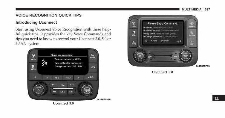
VOICE RECOGNITION QUICK TIPS
Introducing Uconnect
Start using Uconnect Voice Recognition with these help-ful quick tips. It provides the key Voice Commands andtips you need to know to control your Uconnect 3.0, 5.0 or6.5AN system.
Uconnect 3.0
Uconnect 5.0
11
MULTIMEDIA 637

Get Started
All you need to control your Uconnect system with yourvoice are the buttons on your steering wheel.
1. Visit UconnectPhone.com to check mobile device andfeature compatibility and to find phone pairinginstructions.
2. Reduce background noise. Wind and passenger con-versations are examples of noise that may impactrecognition.
3. Speak clearly at a normal pace and volume whilefacing straight ahead. The microphone is positionedon the rearview mirror and aimed at the driver.
4. Each time you give a Voice Command, you must firstpush either the VR or Phone button, wait until afterthe beep, then say your Voice Command.
Uconnect 6.5AN
638 MULTIMEDIA

5. You can interrupt the help message or system promptsby pushing the VR or Phone button and saying a VoiceCommand from current category.
Basic Voice Commands
The basic Voice Commands below can be given at anypoint while using your Uconnect system.
Push the VR button . After the beep, say�
• Cancel to stop a current voice session.
• Help to hear a list of suggested Voice Commands.
• Repeat to listen to the system prompts again.
Uconnect Voice Command Buttons1 — Push To Initiate Or To Answer A Phone Call, Send Or Re-ceive A Text2 — Push To Begin Radio, Navigation, Or Media functions3 — Push To End Call
11
MULTIMEDIA 639

Notice the visual cues that inform you of your voicerecognition system’s status. Cues appear on the touch-screen.
Uconnect 3.0
Uconnect 5.0
640 MULTIMEDIA

Radio
Use your voice to quickly get to the AM, FM or SiriusXMSatellite Radio stations you would like to hear. (Subscrip-tion or included SiriusXM Satellite Radio trial required.)
Push the VR button . After the beep, say�
• Tune to ninety-five-point-five FM.
• Tune to Satellite Channel Hits 1.
Uconnect 6.5AN
11
MULTIMEDIA 641

TIP: At any time, if you are not sure of what to say orwant to learn a Voice Command, press the VR button
and say “Help.” The system will provide you witha list of commands.
Uconnect 5.0 Radio
Uconnect 6.5AN Radio
642 MULTIMEDIA

Media
Uconnect offers connections via USB Port, Bluetooth andAuxiliary Ports (If Equipped). Voice operation is onlyavailable for connected USB and iPod devices. (RemoteCD player optional and not available on all vehicles.)
Push the VR button . After the beep, say one of thefollowing commands and follow the prompts toswitch your media source or choose an artist.
• Change source to Bluetooth.
• Change source to iPod.
• Change source to USB.
• Play artist Beethoven; Play album Greatest Hits; Playsong Moonlight Sonata; Play genre Classical.
TIP: For the Uconnect 5.0 and 6.5AN systems, press theBrowse button on the touchscreen to see all of the musicon your iPod or USB device. Your Voice Command mustmatch exactly how the artist, album, song and genreinformation is displayed.
Uconnect 5.0 Media11
MULTIMEDIA 643
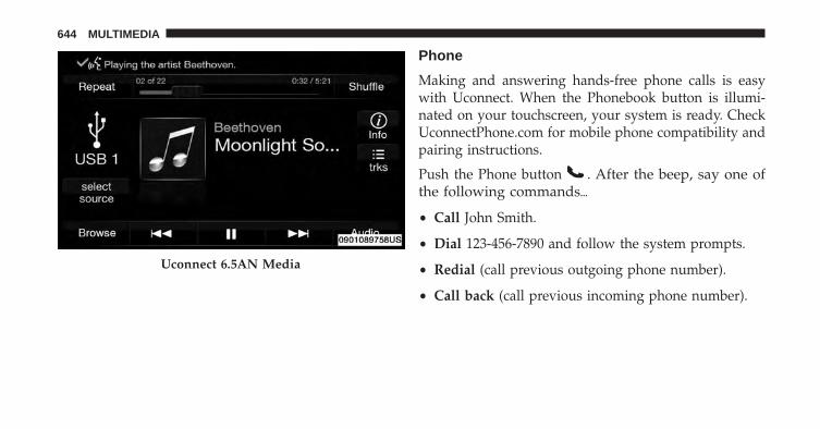
Phone
Making and answering hands-free phone calls is easywith Uconnect. When the Phonebook button is illumi-nated on your touchscreen, your system is ready. CheckUconnectPhone.com for mobile phone compatibility andpairing instructions.
Push the Phone button . After the beep, say one ofthe following commands�
• Call John Smith.
• Dial 123-456-7890 and follow the system prompts.
• Redial (call previous outgoing phone number).
• Call back (call previous incoming phone number).
Uconnect 6.5AN Media
644 MULTIMEDIA

TIP: When providing a Voice Command, push the Phonebutton and say “Call,” then pronounce the nameexactly as it appears in your phone book. When acontact has multiple phone numbers, you can say“Call John Smith work.”
Uconnect 5.0 Phone
Uconnect 6.5AN Phone
11
MULTIMEDIA 645

Voice Text Reply
Uconnect will announce incoming text messages. Pushthe Phone button and say “Listen.” (Must havecompatible mobile phone paired to Uconnect system.)
1. Once an incoming text message is read to you, pushthe Phone button . After the beep, say: “Reply.”
2. Listen to the Uconnect prompts. After the beep, repeatone of the pre-defined messages and follow the systemprompts.
PRE-DEFINED VOICE TEXT REPLY RESPONSESYes. Stuck in Traffic. See you later.
No. Start withoutme. I’ll be Late.
Okay. Where are you? I will be<number>
minutes late.Call me. Are you thereyet?
PRE-DEFINED VOICE TEXT REPLY RESPONSESI’ll call you
later.I need
directions.See you in
<number> ofminutes.I’m on my way. Can’t talk right
now.I’m lost. Thanks.
TIP: Your mobile phone must have the full implementa-tion of the Message Access Profile (MAP) to take advan-tage of this feature. For details about MAP, visitUconnectPhone.com. Apple iPhone iOS6 or later sup-ports reading incoming text messages only.
646 MULTIMEDIA

Navigation (6.5AN)
The Uconnect navigation feature helps you save time andbecome more productive when you know exactly how toget to where you want to go.
1. To enter a destination, push the VR button . Afterthe beep, say:
• For the 6.5AN Uconnect System, say: “Navigate to800 Chrysler Drive Auburn Hills, Michigan.”
2. Then follow the system prompts.
TIP: To start a POI search, push the VR button . Afterthe beep, say: “ Find nearest coffee shop.” Uconnect 6.5AN Navigation
11
MULTIMEDIA 647

Uconnect Access* (6.5A/6.5AN)
WARNING!
Some Uconnect Access services, including 9-1-1 andassist will NOT work without an operable 1X (voice/data) or 3G (data) network connection.
NOTE: Your vehicle may be transmitting data as autho-rized by the subscriber.
An included trial and/or subscription is required to takeadvantage of the Uconnect Access services in the nextsection of this guide. To register with Uconnect Access,push the MORE button below the 6.5-inch touchscreen toget started. Detailed registration instructions can befound on the next page.
*Uconnect Access is available only on equipped vehiclespurchased within the continental United States, Alaskaand Hawaii. Services can only be used where coverage isavailable; see coverage map for details.
9-1-1 Call
Security Alarm Notification
Remote Door Lock/Unlock
Stolen Vehicle Assistance
Remote Vehicle Start**
Remote Horn and Lights
Yelp Search
Voice Texting
Roadside Assistance Call
3G Wi-Fi Hotspot***
**If vehicle is equipped.
***Extra charges apply.
648 MULTIMEDIA

Registration (6.5A/6.5AN)
1. Push the ASSIST button located in the overheadconsole.
2. Press the “Uconnect Care” button on the touchscreen.
3. A helpful Uconnect Care Agent will register yourvehicle and handle all of the details.
Signing up is easy! Simply follow the steps above. Or,press the “Apps ” button on the touchscreen to“Register By Web” to complete the process using yourwireless device or computer.
For further information please visit DriveUconnect.com.
11
MULTIMEDIA 649
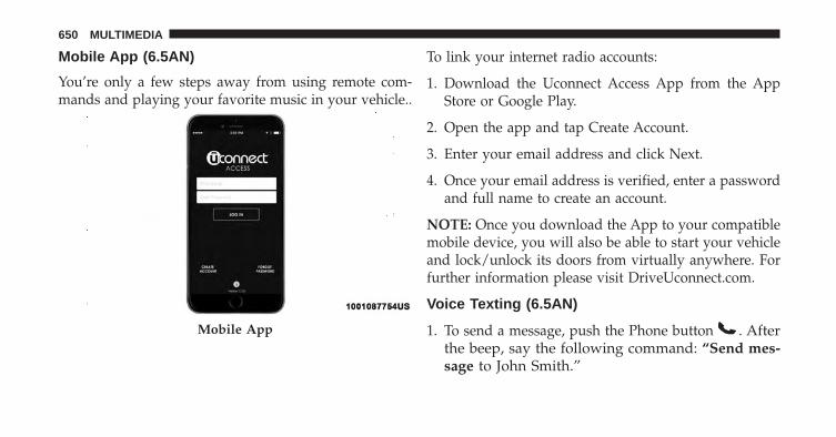
Mobile App (6.5AN)
You’re only a few steps away from using remote com-mands and playing your favorite music in your vehicle..
To link your internet radio accounts:
1. Download the Uconnect Access App from the AppStore or Google Play.
2. Open the app and tap Create Account.
3. Enter your email address and click Next.
4. Once your email address is verified, enter a passwordand full name to create an account.
NOTE: Once you download the App to your compatiblemobile device, you will also be able to start your vehicleand lock/unlock its doors from virtually anywhere. Forfurther information please visit DriveUconnect.com.
Voice Texting (6.5AN)
1. To send a message, push the Phone button . Afterthe beep, say the following command: “Send mes-sage to John Smith.”
Mobile App
650 MULTIMEDIA

2. Listen to the prompt. After the beep, dictate themessage you would like to send. Wait for Uconnect toprocess your message.
3. The Uconnect system will repeat your message andprovide a variety of options to add to, delete, send orhear the message again. After the beep, tell Uconnectwhat you’d like to do. For instance, if you’re happywith your message, after the beep, say: “Send.”
You must be registered with Uconnect Access and have acompatible MAP – enabled smartphone to use your voiceto send a personalized text message.
TIP:
• Not compatible with iPhone.
• Messages are limited to 140 characters.
• The Messaging button on the touchscreen must beilluminated to use the feature.
Yelp (6.5AN)
Once registered with Uconnect Access, you can use yourvoice to search for the most popular places or thingsaround you.
1. Push the MORE button on the faceplate.
2. Press the “Apps” button then the “All Apps” buttonon the touchscreen.
3. Press the “Yelp” button on the touchscreen.
4. Once the YELP home screen appears, push the VRbutton , then say: “YELP search.”
5. Listen to the system prompts and after the beep, tellUconnect the place or business that you’d likeUconnect to find.
11
MULTIMEDIA 651

TIP: Once you perform a search, you can reorganize theresults by selecting either the Best Match, Rating orDistance tab on the top of the touchscreen display.
SiriusXM Travel Link (6.5AN)
Need to find a gas station, view local movie listings,check a sports score or the 5 - day weather forecast?SiriusXM Travel Link is a suite of services that brings awealth of information right to your Uconnect 6.5ANsystem.
Push the VR button . After the beep, say one of thefollowing commands:
• Show fuel prices.
• Show 5 - day weather forecast.
• Show extended weather.
Yelp
652 MULTIMEDIA

TIP: Traffic alerts are not accessible with Voice Com-mand.
General Information
This device complies with FCC rules Part 15 and IndustryCanada RSS-210. Operation is subject to the followingtwo conditions:
1. This device may not cause harmful interference.
2. This device must accept any interference that may bereceived including interference that may cause unde-sired operation.
NOTE:
• The transmitter has been tested and it complies withFCC and IC rules. Changes or modifications not ex-pressly approved by the party responsible for compli-ance could void the user’s authority to operate thedevice.SiriusXM Travel Link
11
MULTIMEDIA 653

• The term IC before the certification/registration num-ber only signifies that Industry Canada technical speci-fications were met.
Additional Information
© 2016 FCA US LLC. All rights reserved. Mopar andUconnect are registered trademarks and Mopar OwnerConnect is a trademark of FCA US LLC. Android is atrademark of Google Inc. SiriusXM and all related marksand logos are trademarks of SiriusXM Radio Inc. Yelp,Yelp logo, Yelp burst and related marks are registeredtrademarks of Yelp.
For Uconnect system support, call 1-877-855-8400 (24hours a day 7 days a week) or visit DriveUconnect.com.
Uconnect Access Services Support: 1-855-792-4241. Pleasehave your Uconnect Security PIN ready when you call.
654 MULTIMEDIA

INDEX
12
INDEX 655

About Your Brakes . . . . . . . . . . . . . . . . . . . . . . . .227ABS (Anti-Lock Brake System) . . . . . . . . . . . . . . . .229Adding Engine Coolant (Antifreeze) . . . . . . . . . . . .540Adding Fuel . . . . . . . . . . . . . . . . . . . . . . . . . . . . .393Adding Washer Fluid . . . . . . . . . . . . . . . . . . . . . .535Additives, Fuel . . . . . . . . . . . . . . . . . . . . . . . . . . .391Air Bag . . . . . . . . . . . . . . . . . . . . . . . . . . . . .262, 263
Advance Front Air Bag . . . . . . . . . . . . . . . .263, 264Air Bag Operation . . . . . . . . . . . . . . . . . . . . . . .265Air Bag Warning Light . . . . . . . . . . . . . . . . . . .276Driver Knee Air Bag . . . . . . . . . . . . . . . . . . . . .267Event Data Recorder (EDR) . . . . . . . . . . . . . . . .279Front Air Bag . . . . . . . . . . . . . . . . . . . . . . .262, 263If A Deployment Occurs . . . . . . . . . . . . . . . . . .272Knee Impact Bolsters . . . . . . . . . . . . . . . . . . . . .266Maintaining Your Air Bag System . . . . . . . . . . . .278Redundant Air Bag Warning Light . . . . . . . . . . .277Side Air Bags . . . . . . . . . . . . . . . . . . . . . . . . . .267Transporting Pets . . . . . . . . . . . . . . . . . . . . . . .301
Air Bag Deployment . . . . . . . . . . . . . . . . . . . . . . .262Air Bag Light . . . . . . . . . . . . . . . . . . . . .185, 276, 303Air Bag Maintenance . . . . . . . . . . . . . . . . . . . . . . .278Air Cleaner, Engine (Engine Air Cleaner Filter) . . . .529Air Conditioner Maintenance . . . . . . . . . .120, 133, 530Air Conditioning . . . . . . . . . . . . . . . . . . . . . .116, 130Air Conditioning Controls . . . . . . . . . . . . . . . . . . .116Air Conditioning Filter . . . . . . . . . . . . . . . . . . . . .531Air Conditioning Refrigerant . . . . . . . . . . . . . .530, 531Air Conditioning System . . . . . . . . . . . . . . . . .116, 530Air Pressure, Tires. . . . . . . . . . . . . . . . . . . . . . . . .572Air Recirculation . . . . . . . . . . . . . . . . . . . . . .119, 129Alarm
Arm The System . . . . . . . . . . . . . . . . . . . . . . . .52Alarm (Security Alarm) . . . . . . . . . . . . . . . . . .51, 188Alarm System (Security Alarm) . . . . . . . . . . . . . . . .51Alterations/Modifications, Vehicle . . . . . . . . . . . . . . .7Antifreeze (Engine Coolant). . . . . . . . . . . . . . .539, 592
Disposal . . . . . . . . . . . . . . . . . . . . . . . . . . . . . .542
656 INDEX

Anti-Lock Brake System (ABS) . . . . . . . . . . . . . . . .229Anti-Lock Warning Light . . . . . . . . . . . . . . . . . . . .203Appearance Care . . . . . . . . . . . . . . . . . . . . . . . . .549Arming System (Security Alarm) . . . . . . . . . . . . . . .51Assist, Hill Start . . . . . . . . . . . . . . . . . . . . . . . . . .234Audio Systems (Radio) . . . . . . . . . . . . . . . . . . . . .631Auto Down Power Windows . . . . . . . . . . . . . . . . .112Automatic Headlights . . . . . . . . . . . . . . . . . . . . . . .95Automatic Temperature Control (ATC)
SYNC Temperature Button . . . . . . . . . . . . . . . . .129Automatic Transmission . . . . . . . . . . . . . .328, 547, 548
Adding Fluid . . . . . . . . . . . . . . . . . . . . . . .548, 594Fluid And Filter Changes . . . . . . . . . . . . . . . . . .548Fluid Change . . . . . . . . . . . . . . . . . . . . . . . . . .548Fluid Level Check . . . . . . . . . . . . . . . . . . . . . . .548Fluid Type . . . . . . . . . . . . . . . . . . . . . . . . .547, 594Special Additives . . . . . . . . . . . . . . . . . . . . . . .547
Auto Up Power Windows . . . . . . . . . . . . . . . . . . .112Auxiliary Electrical Outlet (Power Outlet) . . . . . . . .165
Auxiliary Power Outlet . . . . . . . . . . . . . . . . . . . . .165Axle Fluid . . . . . . . . . . . . . . . . . . . . . . . . . . . . . .594Axle Lubrication . . . . . . . . . . . . . . . . . . . . . . . . . .594
Battery . . . . . . . . . . . . . . . . . . . . . . . . . . . . .189, 529Charging System Light . . . . . . . . . . . . . . . . . . .189
Belts, Seat. . . . . . . . . . . . . . . . . . . . . . . . . . . . . . .303Blind Spot Monitoring. . . . . . . . . . . . . . . . . . . . . . .85Body Mechanism Lubrication . . . . . . . . . . . . . . . . .532B-Pillar Location . . . . . . . . . . . . . . . . . . . . . . . . . .566Brake Assist System . . . . . . . . . . . . . . . . . . . . . . .232Brake Fluid . . . . . . . . . . . . . . . . . . . . . . . . . . . . .594Brakes . . . . . . . . . . . . . . . . . . . . . . . . . . . . . .227, 544Brake System . . . . . . . . . . . . . . . . . . . . . . . . .227, 544
Anti-Lock (ABS) . . . . . . . . . . . . . . . . . . . . . . . .229Fluid Check . . . . . . . . . . . . . . . . . . . . . . . . . . .594Master Cylinder . . . . . . . . . . . . . . . . . . . . . . . .544Warning Light . . . . . . . . . . . . . . . . . . . . . . . . .186
Brightness, Interior Lights . . . . . . . . . . . . . . . . . . .10412
INDEX 657

Bulbs, Light . . . . . . . . . . . . . . . . . . . . . . . . . . . . .305
Camera, Rear . . . . . . . . . . . . . . . . . . . . . . . . . . . .375Capacities, Fluid . . . . . . . . . . . . . . . . . . . . . . . . . .592Caps, Filler
Oil (Engine) . . . . . . . . . . . . . . . . . . . . . . . . . . .527Carbon Monoxide Warning . . . . . . . . . . . . . . .302, 393Car Washes . . . . . . . . . . . . . . . . . . . . . . . . . . . . .549Certification Label. . . . . . . . . . . . . . . . . . . . . . . . .397Changing A Flat Tire. . . . . . . . . . . . . . . . . . . .472, 557Chart, Tire Sizing . . . . . . . . . . . . . . . . . . . . . . . . .561Check Engine Light (Malfunction Indicator Light) . .511Checking Your Vehicle For Safety . . . . . . . . . . . . . .301Checks, Safety . . . . . . . . . . . . . . . . . . . . . . . . . . .301Child Restraint . . . . . . . . . . . . . . . . . . . . . . . . . . .280Child Restraints
Booster Seats . . . . . . . . . . . . . . . . . . . . . . . . . .284Child Restraints . . . . . . . . . . . . . . . . . . . . . . . .280Child Seat Installation . . . . . . . . . . . . . . . . . . . .298
How To Stow An Unused ALR Seat Belt . . . . . . .294Infants And Child Restraints . . . . . . . . . . . . . . .282Install A LATCH-Compatible Child Restraint . . . .293Installing Child Restraints Using The VehicleSeat Belt . . . . . . . . . . . . . . . . . . . . . . . . . . . . . .295LATCH Positions . . . . . . . . . . . . . . . . . . . . . . .288Locating The LATCH Anchorages . . . . . . . . . . . .291Lower Anchors And Tethers For Children . . . . . .287Older Children And Child Restraints . . . . . . . . .283Seating Positions . . . . . . . . . . . . . . . . . . . . . . . .286
Child Safety Locks . . . . . . . . . . . . . . . . . . . . . . . . .64Clean Air Gasoline . . . . . . . . . . . . . . . . . . . . . . . .389Cleaning
Wheels . . . . . . . . . . . . . . . . . . . . . . . . . . . . . . .551Windshield Wiper Blades . . . . . . . . . . . . . . . . . .532
Climate Control . . . . . . . . . . . . . . . . . . . . . . . . . .114Automatic . . . . . . . . . . . . . . . . . .120, 125, 126, 132Manual . . . . . . . . . . . . . . . . . . . . . . . . . . . . . .114
Clutch . . . . . . . . . . . . . . . . . . . . . . . . . . . . . . . . .544
658 INDEX

Clutch Fluid . . . . . . . . . . . . . . . . . . . . . . . . . . . . .544Coin Holder . . . . . . . . . . . . . . . . . . . . . . . . . . . . .170Cold Weather Operation . . . . . . . . . . . . . . . . . . . .314Connector
UCI . . . . . . . . . . . . . . . . . . . . . . . . . . . . . . . . .632Universal Consumer Interface (UCI) . . . . . . . . . .632
Console . . . . . . . . . . . . . . . . . . . . . . . . . . . . . . . .170Console, Floor . . . . . . . . . . . . . . . . . . . . . . . . . . .170Contract, Service. . . . . . . . . . . . . . . . . . . . . . . . . . .13Cooling System. . . . . . . . . . . . . . . . . . . . . . . . . . .538
Adding Coolant (Antifreeze) . . . . . . . . . . . . . . .540Coolant Capacity . . . . . . . . . . . . . . . . . . . . . . .592Coolant Level . . . . . . . . . . . . . . . . . . . . . .538, 542Disposal Of Used Coolant . . . . . . . . . . . . . . . . .542Drain, Flush, And Refill . . . . . . . . . . . . . . . . . . .539Inspection . . . . . . . . . . . . . . . . . . . . . . . . . . . .542Points To Remember . . . . . . . . . . . . . . . . . .541, 543Pressure Cap . . . . . . . . . . . . . . . . . . . . . . . . . .541Selection Of Coolant (Antifreeze) . . . . . .539, 592, 593
Corrosion Protection . . . . . . . . . . . . . . . . . . . . . . .549Cruise Light. . . . . . . . . . . . . . . . . . . . . . . . . .205, 207Cupholders . . . . . . . . . . . . . . . . . . . . . . . . . . . . .171Customer Assistance . . . . . . . . . . . . . . . . . . . . . . . .11Customer Programmable Features . . . . . . . . . . . . .600
Data Recorder, Event . . . . . . . . . . . . . . . . . . . . . . .279Daytime Running Lights . . . . . . . . . . . . . . . . . . . . .96Dealer Service. . . . . . . . . . . . . . . . . . . . . . . . . . . .512Defroster, Rear Window . . . . . . . . . . . . . .108, 119, 132Defroster, Windshield . . . . . . . . . . . . . . . .117, 131, 303Dimmer Switch, Headlight . . . . . . . . . . . . . . . . . . .98Disabled Vehicle Towing . . . . . . . . . . . . . . . . . . . .502Disposal
Antifreeze (Engine Coolant) . . . . . . . . . . . . . . . .542Door Ajar . . . . . . . . . . . . . . . . . . . . . . . . . . .191, 192Door Ajar Light . . . . . . . . . . . . . . . . . . . . . . .191, 192Door Locks
Door Locks . . . . . . . . . . . . . . . . . . . . . . . . . . . .5412
INDEX 659

Key Fob . . . . . . . . . . . . . . . . . . . . . . . . . . . . . . .54Remote . . . . . . . . . . . . . . . . . . . . . . . . . . . . . . .54Remote Keyless Entry . . . . . . . . . . . . . . . . . . . . .54
Driver’s Seat Back Tilt . . . . . . . . . . . . . . . . . . . . . . .66Driving . . . . . . . . . . . . . . . . . . . . . . . . . . . . . . . .399
Electrical Outlet, Auxiliary (Power Outlet) . . . . . . . .165Electric Park Brake . . . . . . . . . . . . . . . . . . . . . . . .317Electric Parking Brake . . . . . . . . . . . . . . . . . . . . . .317Electronic Roll Mitigation (ERM) . . . . . . . . . . . . . .233Electronic Speed Control (Cruise Control) . . . . . . . .340Electronic Stability Control (ESC) . . . . . . . . . . .228, 238Electronic Vehicle Information Center (EVIC) . . . . . .375
Electronic Vehicle Information Center (EVIC) . . . .209Emergency, In Case Of
Hazard Warning Flasher . . . . . . . . . . . . . . . . . .423Jacking . . . . . . . . . . . . . . . . . . . . . . . . . . .472, 557Jump Starting . . . . . . . . . . . . . . . . . . . . . . . . . .487Overheating . . . . . . . . . . . . . . . . . . . . . . . . . . .494
Tow Hooks . . . . . . . . . . . . . . . . . . . . . . . . . . . .505Towing . . . . . . . . . . . . . . . . . . . . . . . . . . . . . .502
Emission Control System Maintenance . . . . . . . . . .511Engine
Air Cleaner . . . . . . . . . . . . . . . . . . . . . . . . . . .529Break-In Recommendations . . . . . . . . . . . . . . . .316Checking Oil Level . . . . . . . . . . . . . . . . . . . . . .525Compartment . . . . . . . . . . . . . . . . . . . . . . . . . .523Coolant (Antifreeze) . . . . . . . . . . . . . . . . . . . . .593Cooling . . . . . . . . . . . . . . . . . . . . . . . . . . . . . .538Exhaust Gas Caution . . . . . . . . . . . . . . . . .302, 393Fails To Start . . . . . . . . . . . . . . . . . . . . . . . . . .312Flooded, Starting . . . . . . . . . . . . . . . . . . . . . . .312Fuel Requirements . . . . . . . . . . . . . . . . . . . . . .388Jump Starting . . . . . . . . . . . . . . . . . . . . . . . . . .487Oil . . . . . . . . . . . . . . . . . . . . . . . . . . .525, 592, 593Oil Filler Cap . . . . . . . . . . . . . . . . . . . . . . . . . .527Oil Filter . . . . . . . . . . . . . . . . . . . . . . . . . . . . .528Oil Selection . . . . . . . . . . . . . . . . . . . . . . .527, 592
660 INDEX

Overheating . . . . . . . . . . . . . . . . . . . . . . . . . . .494Starting . . . . . . . . . . . . . . . . . . . . . . . . . . . . . .311
Engine Oil Viscosity . . . . . . . . . . . . . . . . . . . . . . .527Engine Oil Viscosity Chart . . . . . . . . . . . . . . . . . . .527Ethanol . . . . . . . . . . . . . . . . . . . . . . . . . . . . . . . .390Event Data Recorder . . . . . . . . . . . . . . . . . . . . . . .279Exhaust Gas Caution . . . . . . . . . . . . . . . . . . .302, 393Exhaust System . . . . . . . . . . . . . . . . . . . . . . .302, 535Exterior Lighting . . . . . . . . . . . . . . . . . . . . . . . . . .95Exterior Lights. . . . . . . . . . . . . . . . . . . . . . . . .95, 305
FiltersAir Cleaner . . . . . . . . . . . . . . . . . . . . . . . . . . .529Air Conditioning . . . . . . . . . . . . . . . . . . . . . . .531Engine Oil . . . . . . . . . . . . . . . . . . . . . . . . .528, 593Engine Oil Disposal . . . . . . . . . . . . . . . . . . . . .528
FlashersHazard Warning . . . . . . . . . . . . . . . . . . . . . . . .423Turn Signal . . . . . . . . . . . . . . . . . . . . . .98, 204, 305
Flash-To-Pass . . . . . . . . . . . . . . . . . . . . . . . . . . . . .97Flooded Engine Starting . . . . . . . . . . . . . . . . . . . .312Floor Console . . . . . . . . . . . . . . . . . . . . . . . . . . . .170Fluid, Brake . . . . . . . . . . . . . . . . . . . . . . . . . . . . .594Fluid Capacities . . . . . . . . . . . . . . . . . . . . . . . . . .592Fluid Leaks . . . . . . . . . . . . . . . . . . . . . . . . . . . . .305Fluids, Lubricants And Genuine Parts . . . . . . . . . . .593Fog Lights . . . . . . . . . . . . . . . . . . . . . . . . . . . . . . .96Forward Collision Warning . . . . . . . . . . . . . . . . . .349Freeing A Stuck Vehicle . . . . . . . . . . . . . . . . . . . . .500Fuel . . . . . . . . . . . . . . . . . . . . . . . . . . . . . . . . . . .388
Adding . . . . . . . . . . . . . . . . . . . . . . . . . . . . . .393Additives . . . . . . . . . . . . . . . . . . . . . . . . . . . . .391Clean Air . . . . . . . . . . . . . . . . . . . . . . . . . . . . .389Ethanol . . . . . . . . . . . . . . . . . . . . . . . . . . . . . .390Gasoline . . . . . . . . . . . . . . . . . . . . . . . . . . . . . .388Light . . . . . . . . . . . . . . . . . . . . . . . . . . . . . . . .202Materials Added . . . . . . . . . . . . . . . . . . . . . . . .391Methanol . . . . . . . . . . . . . . . . . . . . . . . . . . . . .390
12
INDEX 661

Octane Rating . . . . . . . . . . . . . . . . . . . . . .388, 593Requirements . . . . . . . . . . . . . . . . . . . . . . . . . .388Specifications . . . . . . . . . . . . . . . . . . . . . . . . . .593Tank Capacity . . . . . . . . . . . . . . . . . . . . . . . . . .592
Gasoline, Clean Air . . . . . . . . . . . . . . . . . . . . . . . .389Gasoline (Fuel) . . . . . . . . . . . . . . . . . . . . . . . . . . .388Gasoline, Reformulated . . . . . . . . . . . . . . . . . . . . .389Gear Ranges . . . . . . . . . . . . . . . . . . . . . . . . . . . . .325Gear Select Lever Override . . . . . . . . . . . . . . . . . .495General Information . . . . . . . . . . . . . . . . . . . . . . .358General Maintenance. . . . . . . . . . . . . . . . . . . . . . .525Glass Cleaning . . . . . . . . . . . . . . . . . . . . . . . . . . .555Gross Axle Weight Rating . . . . . . . . . . . . . . . . . . .406Gross Vehicle Weight Rating. . . . . . . . . . . . . . . . . .405GVWR . . . . . . . . . . . . . . . . . . . . . . . . . . . . . . . . .397
Hazard Warning Flasher . . . . . . . . . . . . . . . . . . . .423
HeadlightsAutomatic . . . . . . . . . . . . . . . . . . . . . . . . . . . . .95Cleaning . . . . . . . . . . . . . . . . . . . . . . . . . . . . .555Delay . . . . . . . . . . . . . . . . . . . . . . . . . . . . . . . .97High Beam/Low Beam Select Switch . . . . . . . . . .98Lights On Reminder . . . . . . . . . . . . . . . . . . . . . .96Passing . . . . . . . . . . . . . . . . . . . . . . . . . . . . . . .97Switch . . . . . . . . . . . . . . . . . . . . . . . . . . . . . . . .95Time Delay . . . . . . . . . . . . . . . . . . . . . . . . . . . .97
Head Restraints . . . . . . . . . . . . . . . . . . . . . . . . . . .76Head Rests . . . . . . . . . . . . . . . . . . . . . . . . . . . . . .76Heated Mirrors. . . . . . . . . . . . . . . . . . . . . . . . . . . .85Heater . . . . . . . . . . . . . . . . . . . . . . . . . . . . . . . . .116High Beam/Low Beam Select (Dimmer) Switch. . . . .98Hill Descent Control . . . . . . . . . . . . . . . . . . . . . . .235Hill Descent Control Indicator . . . . . . . . . . . . . . . .235Hill Start Assist. . . . . . . . . . . . . . . . . . . . . . . . . . .234Hitches
Trailer Towing . . . . . . . . . . . . . . . . . . . . . . . . .408
662 INDEX

Holder, Coin. . . . . . . . . . . . . . . . . . . . . . . . . . . . .170Holder, Cup . . . . . . . . . . . . . . . . . . . . . . . . . . . . .171Hood Prop . . . . . . . . . . . . . . . . . . . . . . . . . . . . . .148Hood Release . . . . . . . . . . . . . . . . . . . . . . . . . . . .148
IgnitionKey . . . . . . . . . . . . . . . . . . . . . . . . . . . . . . . . . .40
Ignition Key Removal . . . . . . . . . . . . . . . . . . . . . .498Immobilizer (Sentry Key) . . . . . . . . . . . . . . . . . . . .49Inside Rearview Mirror. . . . . . . . . . . . . . . . . . .81, 423Instrument Cluster . . . . . . . . . . . . . .177, 189, 190, 204Instrument Panel Cover . . . . . . . . . . . . . . . . . . . . .555Instrument Panel Lens Cleaning . . . . . . . . . . . . . . .556Interior And Instrument Lights . . . . . . . . . . . . . . . .99Interior Appearance Care . . . . . . . . . . . . . . . . . . . .553Interior Lights . . . . . . . . . . . . . . . . . . . . . . . . . . . .99Intermittent Wipers (Delay Wipers). . . . . . . . . . . . .105Introduction . . . . . . . . . . . . . . . . . . . . . . . . . . . . . .4
Inverter, Power . . . . . . . . . . . . . . . . . . . . . . . . . . .167
Jacking Instructions . . . . . . . . . . . . . . . . . . . . . . . .475Jack Location . . . . . . . . . . . . . . . . . . . . . . . . . . . .473Jack Operation. . . . . . . . . . . . . . . . . . . . .472, 475, 557Jump Starting . . . . . . . . . . . . . . . . . . . . . . . . . . . .487
Key FobArm The Alarm . . . . . . . . . . . . . . . . . . . . . . . . .52Keyless Entry . . . . . . . . . . . . . . . . . . . . . . . . . . .57Programming Additional Key Fobs . . . . . . . . . . .39
Key Fob Programming (Remote Keyless Entry) . . . . .39Key Fob, Remote Keyless Entry . . . . . . . . . . . . . . . .31Keyless Enter-N-Go . . . . . . . . . . . . . . . . . . . . . . . .57
Enter The Trunk . . . . . . . . . . . . . . . . . . . . . . . . .57Key Fob . . . . . . . . . . . . . . . . . . . . . . . . . . . . . . .57Lock The Vehicle’s Doors . . . . . . . . . . . . . . .57, 626Passive Entry . . . . . . . . . . . . . . . . . . . . . . . . . . .57Passive Entry Programming . . . . . . . . . . . . .57, 626
12
INDEX 663

Remote Control . . . . . . . . . . . . . . . . . . . . . . . . .57Unlock From The Driver’s Side . . . . . . . . . . . . . .57Unlock From The Passenger Side . . . . . . . . . . . . .57Unlock Liftgate . . . . . . . . . . . . . . . . . . . . . . . . .626
Keyless Entry System . . . . . . . . . . . . . . . . . . . . . . .31Key, Replacement . . . . . . . . . . . . . . . . . . . . . . . . . .39Keys. . . . . . . . . . . . . . . . . . . . . . . . . . . . . . . . .31, 40Key, Sentry (Immobilizer) . . . . . . . . . . . . . . . . . . . .49
Lane Change And Turn Signals . . . . . . . . . . . . . . . .98LaneSense . . . . . . . . . . . . . . . . . . . . . . . . . . . . . .359Lap/Shoulder Belts . . . . . . . . . . . . . . . . . . . . . . . .249Latches . . . . . . . . . . . . . . . . . . . . . . . . . . . . . . . .305Lead Free Gasoline . . . . . . . . . . . . . . . . . . . . . . . .388Leaks, Fluid . . . . . . . . . . . . . . . . . . . . . . . . . . . . .305Life Of Tires . . . . . . . . . . . . . . . . . . . . . . . . . . . . .578Liftgate . . . . . . . . . . . . . . . . . . . . . . . . . . . . . . . .150Liftgate Window Wiper/Washer . . . . . . . . . . . . . . .108Light Bulbs. . . . . . . . . . . . . . . . . . . . . . . . . . . . . .305
Lights . . . . . . . . . . . . . . . . . . . . . . . . . . . . . . . . .305Air Bag . . . . . . . . . . . . . . . . . . . . . . . .185, 276, 303Automatic Headlights . . . . . . . . . . . . . . . . . . . . .95Brake Assist Warning . . . . . . . . . . . . . . . . . . . .243Brake Warning . . . . . . . . . . . . . . . . . . . . . . . . .186Cruise . . . . . . . . . . . . . . . . . . . . . . . . . . . .205, 207Daytime Running . . . . . . . . . . . . . . . . . . . . . . . .96Dimmer Switch, Headlight . . . . . . . . . . . . . . . . .98Engine Temperature Warning . . . . . . . . . . . . . . .190Exterior . . . . . . . . . . . . . . . . . . . . . . . . . . . . . .305Fog . . . . . . . . . . . . . . . . . . . . . . . . . . . . . . . . . .96Hazard Warning Flasher . . . . . . . . . . . . . . . . . .423Headlights . . . . . . . . . . . . . . . . . . . . . . . . . . . . .95Headlights On Reminder . . . . . . . . . . . . . . . . . . .96Headlight Switch . . . . . . . . . . . . . . . . . . . . . . . .95High Beam . . . . . . . . . . . . . . . . . . . . . . . . . . . .98High Beam/Low Beam Select . . . . . . . . . . . . . . .98Hill Descent Control Indicator . . . . . . . . . . . . . .235Instrument Cluster . . . . . . . . . . . . . . . . . . . . . . .95
664 INDEX

Intensity Control . . . . . . . . . . . . . . . . . . . . . . . .104Interior . . . . . . . . . . . . . . . . . . . . . . . . . . . . . . .99Lights On Reminder . . . . . . . . . . . . . . . . . . . . . .96Low Fuel . . . . . . . . . . . . . . . . . . . . . . . . . . . . .202Malfunction Indicator (Check Engine) . . . . . . . . .200Park . . . . . . . . . . . . . . . . . . . . . . . . . . . . . . . .204Passing . . . . . . . . . . . . . . . . . . . . . . . . . . . . . . .97Seat Belt Reminder . . . . . . . . . . . . . . . . . . . . . .184Security Alarm . . . . . . . . . . . . . . . . . . . . . . . . .188Tire Pressure Monitoring (TPMS) . . . . . . . . .195, 378Traction Control . . . . . . . . . . . . . . . . . . . . . . . .243Turn Signal . . . . . . . . . . . . . . . . . . . . . .98, 204, 305Vanity Mirror . . . . . . . . . . . . . . . . . . . . . . . . . .103Warning (Instrument Cluster Description) . . .190, 204
Loading Vehicle . . . . . . . . . . . . . . . . . . . . . . . . . .397Tires . . . . . . . . . . . . . . . . . . . . . . . . . . . . . . . .566
Locks . . . . . . . . . . . . . . . . . . . . . . . . . . . . . . . . . .54Child Protection . . . . . . . . . . . . . . . . . . . . . . . . .64Door . . . . . . . . . . . . . . . . . . . . . . . . . . . . . . . . .54
Low Tire Pressure System . . . . . . . . . . . . . . . . . . .378Lubrication, Body . . . . . . . . . . . . . . . . . . . . . . . . .532Luggage Carrier . . . . . . . . . . . . . . . . . . . . . . . . . .173Lug Nuts . . . . . . . . . . . . . . . . . . . . . . . . . . . . . . .589
Maintenance Free Battery. . . . . . . . . . . . . . . . . . . .529Maintenance, General . . . . . . . . . . . . . . . . . . . . . .525Maintenance Procedures . . . . . . . . . . . . . . . . . . . .525Maintenance Schedule . . . . . . . . . . . . . . . . . . . . . .513Malfunction Indicator Light (Check Engine) . . .200, 511Manual, Service . . . . . . . . . . . . . . . . . . . . . . . . . . .16Manual Transmission . . . . . . . . . . . . . . . . . . .324, 546
Fluid Level Check . . . . . . . . . . . . . . . . . . . . . . .546Frequency Of Fluid Change . . . . . . . . . . . . . . . .546Lubricant Selection . . . . . . . . . . . . . . . . . . . . . .546Shift Speeds . . . . . . . . . . . . . . . . . . . . . . . . . . .325
Master Cylinder (Brakes) . . . . . . . . . . . . . . . . . . . .544Methanol . . . . . . . . . . . . . . . . . . . . . . . . . . . . . . .390
12
INDEX 665

MirrorsHeated . . . . . . . . . . . . . . . . . . . . . . . . . . . . . . .85Outside . . . . . . . . . . . . . . . . . . . . . . . . . . . . . . .83Rearview . . . . . . . . . . . . . . . . . . . . . . . . . .81, 423Vanity . . . . . . . . . . . . . . . . . . . . . . . . . . . . . . .103
Modifications/Alterations, Vehicle . . . . . . . . . . . . . . .7Monitor, Tire Pressure System . . . . . . . . . . . . . . . .378MTBE/ETBE . . . . . . . . . . . . . . . . . . . . . . . . . . . .390
New Vehicle Break-In Period . . . . . . . . . . . . . . . . .316
Occupant Restraints . . . . . . . . . . . . . . . . . . . . . . .246Octane Rating, Gasoline (Fuel) . . . . . . . . . . . . .388, 593Oil, Engine . . . . . . . . . . . . . . . . . . . . . . . . . .525, 593
Capacity . . . . . . . . . . . . . . . . . . . . . . . . . . . . .592Change Interval . . . . . . . . . . . . . . . . . . . . . . . .526Checking . . . . . . . . . . . . . . . . . . . . . . . . . . . . .525Disposal . . . . . . . . . . . . . . . . . . . . . . . . . . . . . .528Filter . . . . . . . . . . . . . . . . . . . . . . . . . . . . .528, 593
Filter Disposal . . . . . . . . . . . . . . . . . . . . . . . . .528Materials Added To . . . . . . . . . . . . . . . . . . . . . .528Pressure Warning Light . . . . . . . . . . . . . . . . . . .188Recommendation . . . . . . . . . . . . . . . . . . . .527, 592Viscosity . . . . . . . . . . . . . . . . . . . . . . . . . .527, 592
Oil Filter, Change . . . . . . . . . . . . . . . . . . . . . . . . .528Oil Filter, Selection . . . . . . . . . . . . . . . . . . . . . . . .528Oil Pressure Light . . . . . . . . . . . . . . . . . . . . . . . . .188Onboard Diagnostic System . . . . . . . . . . . . . . . . . .208Operating Precautions . . . . . . . . . . . . . . . . . . . . . .208Operator Manual (Owner’s Manual) . . . . . . . . . . . . .5Outside Rearview Mirrors . . . . . . . . . . . . . . . . . . . .83Overheating, Engine . . . . . . . . . . . . . . . . . . . . . . .494Owner’s Manual (Operator Manual) . . . . . . . . . . .5, 16
Paint Care . . . . . . . . . . . . . . . . . . . . . . . . . . . . . .549Parking Brake. . . . . . . . . . . . . . . . . . . . . . . . . . . .317ParkSense System, Rear . . . . . . . . . . . . . . . . . . . . .369Pets . . . . . . . . . . . . . . . . . . . . . . . . . . . . . . . . . . .301Placard, Tire And Loading Information . . . . . . . . . .567
666 INDEX

PowerBrakes . . . . . . . . . . . . . . . . . . . . . . . . . . . . . . .227Inverter . . . . . . . . . . . . . . . . . . . . . . . . . . . . . .167Outlet (Auxiliary Electrical Outlet) . . . . . . . . . . .165Windows . . . . . . . . . . . . . . . . . . . . . . . . . . . . .111
Pregnant Women And Seat Belts. . . . . . . . . . . . . . .259Preparation For Jacking . . . . . . . . . . . . . . . . . . . . .474Pretensioners
Seat Belts . . . . . . . . . . . . . . . . . . . . . . . . . . . . .259
Radial Ply Tires . . . . . . . . . . . . . . . . . . . . . . . . . .574Radio Frequency
General Information . . . . . . . . . . . .33, 44, 49, 50, 63Radio Operation . . . . . . . . . . . . . . . . . . . . . . . . . .635Rain Sensitive Wiper System . . . . . . . . . . . . . . . . .106Rear Camera . . . . . . . . . . . . . . . . . . . . . . . . . . . .375Rear Cross Path . . . . . . . . . . . . . . . . . . . . . . . . . . .91Rear ParkSense System . . . . . . . . . . . . . . . . . . . . .369Rearview Mirrors . . . . . . . . . . . . . . . . . . . . . . . . . .81
Rear Window Defroster . . . . . . . . . . . . . . . . . . . . .108Rear Wiper/Washer. . . . . . . . . . . . . . . . . . . . . . . .108Recorder, Event Data . . . . . . . . . . . . . . . . . . . . . . .279Recreational Towing . . . . . . . . . . . . . . . . . . . . . . .418Reformulated Gasoline . . . . . . . . . . . . . . . . . . . . .389Refrigerant . . . . . . . . . . . . . . . . . . . . . . . . . . . . . .531Reminder, Lights On. . . . . . . . . . . . . . . . . . . . . . . .96Reminder, Seat Belt . . . . . . . . . . . . . . . . . . . . . . . .248Remote Control
Starting System . . . . . . . . . . . . . . . . . . . . . . . . .45Remote Keyless Entry . . . . . . . . . . . . . . . . . . . . . . .31
Arm The Alarm . . . . . . . . . . . . . . . . . . . . . . . . .52Keyless Enter-N-Go . . . . . . . . . . . . . . . . . . . . . .57Programming Additional Key Fobs . . . . . . . . . . .39
Remote Sound System (Radio) Controls . . . . . . . . .633Remote Starting
Exit Remote Start Mode . . . . . . . . . . . . . . . . . . .47Uconnect Customer Programmable Features . . . . .48Uconnect Settings . . . . . . . . . . . . . . . . . . . . . . . .48
12
INDEX 667

Remote Starting System. . . . . . . . . . . . . . . . . . . . . .45Replacement Keys . . . . . . . . . . . . . . . . . . . . . . . . .39Replacement Parts. . . . . . . . . . . . . . . . . . . . . . . . .512Replacement Tires . . . . . . . . . . . . . . . . . . . . . . . . .579Reporting Safety Defects . . . . . . . . . . . . . . . . . . . . .15Restraint, Head . . . . . . . . . . . . . . . . . . . . . . . . . . .76Restraints, Child . . . . . . . . . . . . . . . . . . . . . . . . . .280Restraints, Occupant . . . . . . . . . . . . . . . . . . . . . . .246Roll Over Warning . . . . . . . . . . . . . . . . . . . . . . . . . .7Roof Type Carrier . . . . . . . . . . . . . . . . . . . . . . . . .173Rotation, Tires . . . . . . . . . . . . . . . . . . . . . . . . . . .582
Safety Checks Inside Vehicle . . . . . . . . . . . . . . . . .303Safety Checks Outside Vehicle . . . . . . . . . . . . . . . .305Safety Defects, Reporting. . . . . . . . . . . . . . . . . . . . .15Safety, Exhaust Gas . . . . . . . . . . . . . . . . . . . . . . . .302Safety Information, Tire . . . . . . . . . . . . . . . . . . . . .559Safety Tips . . . . . . . . . . . . . . . . . . . . . . . . . . . . . .301Schedule, Maintenance . . . . . . . . . . . . . . . . . . . . .513
Seat BeltAdjustable Upper Shoulder Belt Anchorage . . . . .255Automatic Locking Retractor (ALR) . . . . . . . . . .260Energy Management Feature . . . . . . . . . . . . . . .260Lap/Shoulder Belt Operation . . . . . . . . . . . . . . .252Lap/Shoulder Belts . . . . . . . . . . . . . . . . . . . . . .249Lap/Shoulder Belt Untwisting . . . . . . . . . . . . . .254Pregnant Women . . . . . . . . . . . . . . . . . . . . . . .259Seat Belt Pretensioner . . . . . . . . . . . . . . . . . . . .259Seat Belt Reminder . . . . . . . . . . . . . . . . . . . . . .248Seat Belt System . . . . . . . . . . . . . . . . . . . . . . . .246
Seat Belt Maintenance . . . . . . . . . . . . . . . . . . . . . .556Seat Belt Reminder . . . . . . . . . . . . . . . . . . . . . . . .248Seat Belts. . . . . . . . . . . . . . . . . . . . . . . . . . . .247, 303
Adjustable Shoulder Belt . . . . . . . . . . . . . . . . . .255Adjustable Upper Shoulder Anchorage . . . . . . . .255Child Restraint . . . . . . . . . . . . . . . . . . . . . . . . .280Front Seat . . . . . . . . . . . . . . . . . . . . . .247, 249, 252Inspection . . . . . . . . . . . . . . . . . . . . . . . . . . . .303
668 INDEX

Operating Instructions . . . . . . . . . . . . . . . . . . . .252Pregnant Women . . . . . . . . . . . . . . . . . . . . . . .259Pretensioners . . . . . . . . . . . . . . . . . . . . . . . . . .259Rear Seat . . . . . . . . . . . . . . . . . . . . . . . . . . . . .249Reminder . . . . . . . . . . . . . . . . . . . . . . . . . . . . .184Untwisting Procedure . . . . . . . . . . . . . . . . . . . .254
Seats . . . . . . . . . . . . . . . . . . . . . . . . . . . . . . . . . . .65Adjustment . . . . . . . . . . . . . . . . . . . . . . . . . .65, 66Head Restraints . . . . . . . . . . . . . . . . . . . . . . . . .76Seatback Release . . . . . . . . . . . . . . . . . . . . . . . . .66Tilting . . . . . . . . . . . . . . . . . . . . . . . . . . . . . . . .66
Security Alarm. . . . . . . . . . . . . . . . . . . . . . . . .51, 188Arm The System . . . . . . . . . . . . . . . . . . . . . . . .52
Selection Of Coolant (Antifreeze) . . . . . . . . . . . . . .593Sentry Key (Immobilizer) . . . . . . . . . . . . . . . . . . . .49Sentry Key Replacement . . . . . . . . . . . . . . . . . . . . .39Service Assistance . . . . . . . . . . . . . . . . . . . . . . . . . .11Service Contract . . . . . . . . . . . . . . . . . . . . . . . . . . .13Service Manuals . . . . . . . . . . . . . . . . . . . . . . . . . . .16
ShiftingManual Transmission . . . . . . . . . . . . . . . . . . . .324
Shift Lever Override . . . . . . . . . . . . . . . . . . . . . . .495Shoulder Belts . . . . . . . . . . . . . . . . . . . . . . . . . . .249Side View Mirror Adjustment . . . . . . . . . . . . . . . . .83Signals, Turn. . . . . . . . . . . . . . . . . . . . . . .98, 204, 305Snow Chains (Tire Chains) . . . . . . . . . . . . . . . . . . .581Snow Tires . . . . . . . . . . . . . . . . . . . . . . . . . . . . . .576Spark Plugs . . . . . . . . . . . . . . . . . . . . . . . . . . . . .593Specifications
Fuel (Gasoline) . . . . . . . . . . . . . . . . . . . . . . . . .593Oil . . . . . . . . . . . . . . . . . . . . . . . . . . . . . . . . . .593
Speed Control (Cruise Control). . . . . . . . . . . . . . . .340Starting . . . . . . . . . . . . . . . . . . . . . . . . . . . . . .45, 311
Cold Weather . . . . . . . . . . . . . . . . . . . . . . . . . .314Engine Fails To Start . . . . . . . . . . . . . . . . . . . . .312Remote . . . . . . . . . . . . . . . . . . . . . . . . . . . . . . .45
Starting And Operating . . . . . . . . . . . . . . . . . . . . .311Starting Procedures . . . . . . . . . . . . . . . . . . . . . . . .311
12
INDEX 669

SteeringTilt Column . . . . . . . . . . . . . . . . . . . . . . . . . . . .79Wheel, Heated . . . . . . . . . . . . . . . . . . . . . . . . . .80Wheel, Tilt . . . . . . . . . . . . . . . . . . . . . . . . . . . . .79
Steering Wheel Audio Controls . . . . . . . . . . . . . . .633Steering Wheel Mounted Sound System Controls . . .633Stuck, Freeing. . . . . . . . . . . . . . . . . . . . . . . . . . . .500Sun Visor Extension . . . . . . . . . . . . . . . . . . . . . . .163Supplemental Restraint System - Air Bag. . . . . . . . .263Sway Control, Trailer . . . . . . . . . . . . . . . . . . .244, 407System, Remote Starting . . . . . . . . . . . . . . . . . . . . .45
Telescoping Steering Column . . . . . . . . . . . . . . . . . .79Temperature Control, Automatic (ATC) . . . . . . . . . .126Tilt Steering Column. . . . . . . . . . . . . . . . . . . . . . . .79Time Delay, Headlight. . . . . . . . . . . . . . . . . . . . . . .97Tip Start. . . . . . . . . . . . . . . . . . . . . . . . . . . . . . . .312Tire And Loading Information Placard . . . . . . .566, 567Tire Markings . . . . . . . . . . . . . . . . . . . . . . . . . . . .559
Tires. . . . . . . . . . . . . . . . . . . . . . . . . . . . .17, 305, 571Aging (Life Of Tires) . . . . . . . . . . . . . . . . . . . . .578Air Pressure . . . . . . . . . . . . . . . . . . . . . . . . . . .571Chains . . . . . . . . . . . . . . . . . . . . . . . . . . . . . . .581Changing . . . . . . . . . . . . . . . . . . . . . . . . .472, 557General Information . . . . . . . . . . . . . . . . . . . . .571High Speed . . . . . . . . . . . . . . . . . . . . . . . . . . .574Inflation Pressures . . . . . . . . . . . . . . . . . . . . . . .572Jacking . . . . . . . . . . . . . . . . . . . . . . . . . . .472, 557Life Of Tires . . . . . . . . . . . . . . . . . . . . . . . . . . .578Load Capacity . . . . . . . . . . . . . . . . . . . . . .566, 567Pressure Monitor System (TPMS) . . . . . . . . . . . .378Pressure Warning Light . . . . . . . . . . . . . . . . . . .195Quality Grading . . . . . . . . . . . . . . . . . . . . . . . . .17Radial . . . . . . . . . . . . . . . . . . . . . . . . . . . . . . .574Replacement . . . . . . . . . . . . . . . . . . . . . . . . . . .579Rotation . . . . . . . . . . . . . . . . . . . . . . . . . . . . . .582Safety . . . . . . . . . . . . . . . . . . . . . . . . . . . .559, 571Sizes . . . . . . . . . . . . . . . . . . . . . . . . . . . . . . . .561
670 INDEX

Snow Tires . . . . . . . . . . . . . . . . . . . . . . . . . . . .576Spinning . . . . . . . . . . . . . . . . . . . . . . . . . . . . .577Trailer Towing . . . . . . . . . . . . . . . . . . . . . . . . .413Tread Wear Indicators . . . . . . . . . . . . . . . . . . . .578
Tire Safety Information . . . . . . . . . . . . . . . . . . . . .559Tire Service Kit . . . . . . . . . . . . . . . . . . . . . . . . . . .483Tongue Weight/Trailer Weight . . . . . . . . . . . . . . . .410Tow Hooks, Emergency . . . . . . . . . . . . . . . . . . . . .505Towing . . . . . . . . . . . . . . . . . . . . . . . . . . . . . . . .405
Disabled Vehicle . . . . . . . . . . . . . . . . . . . . . . . .502Guide . . . . . . . . . . . . . . . . . . . . . . . . . . . . . . .409Recreational . . . . . . . . . . . . . . . . . . . . . . . . . . .418Weight . . . . . . . . . . . . . . . . . . . . . . . . . . . . . . .409
Trailer Sway Control (TSC) . . . . . . . . . . . . . . . . . .244Trailer Towing . . . . . . . . . . . . . . . . . . . . . . . . . . .405
Cooling System Tips . . . . . . . . . . . . . . . . . . . . .417Hitches . . . . . . . . . . . . . . . . . . . . . . . . . . . . . .408Minimum Requirements . . . . . . . . . . . . . . . . . .411Trailer And Tongue Weight . . . . . . . . . . . . . . . .410
Wiring . . . . . . . . . . . . . . . . . . . . . . . . . . . . . . .414Trailer Towing Guide. . . . . . . . . . . . . . . . . . . . . . .409Trailer Weight . . . . . . . . . . . . . . . . . . . . . . . . . . . .409Transfer Case
Fluid . . . . . . . . . . . . . . . . . . . . . . . . . . . . . . . .594Transmission
Automatic . . . . . . . . . . . . . . . . . . . . . . . . .328, 547Fluid . . . . . . . . . . . . . . . . . . . . . . . . . . . . . . . .594Manual . . . . . . . . . . . . . . . . . . . . . . . . . . . . . .324
Transporting Pets . . . . . . . . . . . . . . . . . . . . . . . . .301Tread Wear Indicators . . . . . . . . . . . . . . . . . . . . . .578Turn Signals . . . . . . . . . . . . . . . . . . . . . . . . . .98, 204
UCI Connector . . . . . . . . . . . . . . . . . . . . . . . . . . .632Uconnect
Customer Programmable Features . . . . . . . . . . . .48Uconnect Settings . . . . . . . . . . . . . . . . . . . . . . . .48
Uconnect Settings . . . . . . . . . . . . . . . . . . . . . . . . . .33Customer Programmable Features . . . . . . . . . . .626
12
INDEX 671

Passive Entry Programming . . . . . . . . . . . . . . . .626Uconnect Settings . . . . . . . . . . . . . . . . . . . . . . .626
Uconnect Voice Command . . . . . . . . . . . . . . . . . . .637Uniform Tire Quality Grades . . . . . . . . . . . . . . . . . .17Universal Consumer Interface (UCI) Connector . . . .632Unleaded Gasoline . . . . . . . . . . . . . . . . . . . . . . . .388Untwisting Procedure, Seat Belt . . . . . . . . . . . . . . .254
Vanity Mirrors . . . . . . . . . . . . . . . . . . . . . . . . . . .103Vehicle Loading . . . . . . . . . . . . . . . . . . . . . . .397, 567Vehicle Modifications/Alterations . . . . . . . . . . . . . . .7Vehicle Security Alarm (Security Alarm) . . . . . . . . . .51Viscosity, Engine Oil . . . . . . . . . . . . . . . . . . . . . . .527
Warning Flasher, Hazard . . . . . . . . . . . . . . . . . . . .423Warning, Roll Over . . . . . . . . . . . . . . . . . . . . . . . . .7Warnings And Cautions . . . . . . . . . . . . . . . . . . . . . .7Warranty Information . . . . . . . . . . . . . . . . . . . . . . .15
WasherAdding Fluid . . . . . . . . . . . . . . . . . . . . . . . . . .535
Washing Vehicle . . . . . . . . . . . . . . . . . . . . . . . . . .549Wheel And Wheel Trim . . . . . . . . . . . . . . . . . . . . .551Wheel And Wheel Trim Care . . . . . . . . . . . . . . . . .551Wind Buffeting . . . . . . . . . . . . . . . . . . . . . . . . . . .114Windows . . . . . . . . . . . . . . . . . . . . . . . . . . . . . . .111
Power . . . . . . . . . . . . . . . . . . . . . . . . . . . . . . .111Windshield Defroster . . . . . . . . . . . . . . . . . . .117, 303Windshield Wiper Blades . . . . . . . . . . . . . . . . . . . .532Wiper Blade Replacement . . . . . . . . . . . . . . . . . . .532Wipers, Intermittent . . . . . . . . . . . . . . . . . . . . . . .105Wipers, Rain Sensitive . . . . . . . . . . . . . . . . . . . . . .106Wrecker Towing . . . . . . . . . . . . . . . . . . . . . . . . . .502
672 INDEX

INSTALLATION OF RADIO TRANSMITTINGEQUIPMENTSpecial design considerations are incorporated into thisvehicle’s electronic system to provide immunity to radiofrequency signals. Mobile two-way radios and telephoneequipment must be installed properly by trained person-nel. The following must be observed during installation.
The positive power connection should be made directlyto the battery and fused as close to the battery as possible.The negative power connection should be made to bodysheet metal adjacent to the negative battery connection.This connection should not be fused.
Antennas for two-way radios should be mounted on theroof or the rear area of the vehicle. Care should be usedin mounting antennas with magnet bases. Magnets mayaffect the accuracy or operation of the compass onvehicles so equipped.
The antenna cable should be as short as practical androuted away from the vehicle wiring when possible. Useonly fully shielded coaxial cable.
Carefully match the antenna and cable to the radio toensure a low Standing Wave Ratio (SWR).
Mobile radio equipment with output power greater thannormal may require special precautions.
All installations should be checked for possible interfer-ence between the communications equipment and thevehicle’s electronic systems.

RenegadeOW N E R ’ S M A N UA L
20
16 R
en
eg
ad
e
Fifth EditionPrinted in U.S.A.
16BU-126-AE©2016 FCA US LLC. All Rights Reserved.Jeep is a registered trademark of FCA US LLC.
2 0 1 6
STICK WITH THE SPECIALISTS®


