Updated: APR 2018 — 2016 ROAD and BRIDGE SPECIFICATIONS (Division III) — Saved: 04/02/2018 2:37 PM —————————————————————————————————————————————————————————— TOC , VDOT Web , OVDOT , I , II , III , IV , V , VI , VII , VIII , 2018 Supplement , 2016 Spec Book 3-1 2016 ROAD AND BRIDGE SPECIFICATIONS DIVISION III—ROADWAY CONSTRUCTION SPECIAL PROVISION COPIED NOTES (SPCNs), SPECIAL PROVISION (SPs) and SUPPLEMENTAL SPECIFICATIONS (SSs) Specifications may also be found at the following locations: ● VDOT Web (Global Web Access) ● OutsideVDOT_ (Accessible by permission only) ● http://www.virginiadot.org/business/resources/const/2016Rev.zip (“zip” file [compressed WORD ® ])
TOC , VDOT Web , OVDOT , I , II , III , IV , V , VI , VII , VIII , 2018 Supplement , 2016 Spec Book
3-4
GUIDELINES — For projects requiring crushed glass to be a separate pay item. A separate project-specific SPCN must be included that specifies for what and where the crushed glass is used. {2007-c200b00}
cn300-000100-00 CRUSHED GLASS —When not incorporated into the measurement and payment
of other items by specification, crushed glass will be measured and paid for at the contract unit price per ton, which shall be full compensation for furnishing, placing, manipulating and compacting. Deliveries of crushed glass shall conform to Section 109.01(b) of the Specifications. Payment will be made as follows:
Pay Item
Pay Unit
Crushed glass Ton 1-17-08c; Reissued 7-12-16 (SPCN)
TOC , VDOT Web , OVDOT , I , II , III , IV , V , VI , VII , VIII , 2018 Supplement , 2016 Spec Book
3-5
GUIDELINES — Use when requested by the Designer (Not for use in pavement structure and rarely used in bedding material). {2007-c303kg0}
cn303-000100-00 AGGREGATE MATERIAL shall be the size specified conforming to Section 203 of
the Specifications. The aggregate shall be placed at locations shown on the plans or as directed by the Engineer. Aggregate material will be measured in units of tons for the size specified according to Section 109 of the Specifications. Payment will be made at the contract unit price per ton, which bid price shall be full compensation for furnishing, placing, and shaping and compaction, if required. Payment will be made under:
Pay Item
Pay Unit
Aggregate Material (Size) Ton 5-23-95c; Reissued 7-12-16 (SPCN)
TOC , VDOT Web , OVDOT , I , II , III , IV , V , VI , VII , VIII , 2018 Supplement , 2016 Spec Book
3-6
GUIDELINES — Use when extra excavation for a No Plan (N) or Minimum Plan project does not have a contract bid item. Must fill in unit price per cubic yard. {2007-S303DP0}
cn303-060100-00 EXTRA EXCAVATION will be paid for at the unit price of $ fill-in amount per cubic
TOC , VDOT Web , OVDOT , I , II , III , IV , V , VI , VII , VIII , 2018 Supplement , 2016 Spec Book
3-7
GUIDELINES — All projects requiring asphalt concrete pavement. {2007-c315i00}
cn315-000100-00 SECTION 315.05(c) PLACING AND FINISHING is modified by replacing the third
paragraph with the following: The longitudinal joint in one layer shall offset that in the layer immediately below by approximately 6 inches or more. The joint in the wearing surface shall be offset 6 inches to 12 inches from the centerline of the pavement if the roadway comprises two traffic lanes. The joint shall be offset approximately 6 inches from the lane lines if the roadway is more than two lanes in width. The longitudinal joint shall be uniform in appearance. On all roads except secondary routes, if the offset for the longitudinal joint varies from a straight line more than 2 inches in 50 feet on tangent alignment, or from a true arc more than 2 inches in 50 feet on curved alignment, the Contractor shall seal the joint using a water-proof sealer at no cost to the Department. The Contractor shall recommend a sealant and installation procedure to the Engineer for approval before proceeding. On all roads except secondary routes, if the offset for the longitudinal joint varies from a straight line more than 3 inches in 50 feet on tangent alignment, or from a true arc more than 3 inches in 50 feet on curved alignment, the Engineer may reject the paving. The Engineer will not require offsetting layers when adjoining lanes are paved in echelon and the rolling of both lanes occurs within 15 minutes after laydown.
TOC , VDOT Web , OVDOT , I , II , III , IV , V , VI , VII , VIII , 2018 Supplement , 2016 Spec Book
3-8
GRAB STRENGTH FOR PREFABRICATED VERTICAL DRAINS – The geotextile jacket material for Prefabricated Vertical Drains shall conform to Section III-1F of the Special Provision for Prefabricated Vertical Drains, except that Grab Tensile Strength shall be at least 120 lbs when tested in accordance with ASTM D4632. 9-20-17 (SPCN)
TOC , VDOT Web , OVDOT , I , II , III , IV , V , VI , VII , VIII , 2018 Supplement , 2016 Spec Book
3-9
cq308-030100-00
GUIDELINES – All projects that require density testing of subbase or aggregate base according to Sections 308 and 309.
DENSITY TESTING OF SUBBASE OR AGGREGATE BASE — Sections 308 and 309 of the Specifications are amended as follows:
SECTION 308—SUBBASE COURSE is amended as follows:
Section 308.03—Procedures is amended by replacing the last paragraph with the following:
The Department will perform field density determinations with a portable nuclear field density testing device using the density control strip as specified in Section 304 and VTM-10, or by other approved methods as directed by the Engineer.
SECTION 309—AGGREGATE BASE COURSE is amended as follows:
Section 309.05—Density Requirements is amended by replacing the fifth paragraph with the following:
The base course will be tested in place for depth and density. The Department will perform field density determinations with a portable nuclear field density testing device, using a density control strip as specified in Section 304 and VTM-10 as directed by the Engineer.
TOC , VDOT Web , OVDOT , I , II , III , IV , V , VI , VII , VIII , 2018 Supplement , 2016 Spec Book
3-10
cq312-000100-00
GUIDELINES – Use when requested by the Designer. Include SP314-000100-00, SP312-000100-00, SP512-000120-00, and SP704-000100-00.{2007-cu312001a}
CAPE SEAL TREATMENT — This work shall consist of furnishing and applying asphalt surface treatment to the existing roadway surface, allowing sufficient time for curing followed by cleanup, then furnishing and applying emulsified asphalt slurry seal as the finished surface. The sequence of work shall be as follows:
1. The existing asphalt surface shall be patched at locations according to the provisions of this
contract and as directed by the Engineer. 2. All pavement markings shall be eradicated according to the special provision for SECTION 512—
MAINTAINING TRAFFIC (ASPHALT SCHEDULES). 3. Asphalt surface treatment shall be applied according to the special provision for ASPHALT
SURFACE TREATMENT. Asphalt surface treatment shall be a modified single seal or modified double seal with liquid asphalt material of CRS-2L emulsified asphalt, aggregate size No. 8P, and blot coat of No. 9 aggregate.
4. Temporary pavement markings shall be installed and maintained according to the special
provision for SECTION 704—PAVEMENT MARKINGS AND MARKERS. 5. Asphalt surface treatment shall be allowed to cure for two weeks after application. 6. After curing, excess and loose material resulting from the vehicular traffic that occurred during the
asphalt surface treatment curing period shall be removed from the roadway. 7. Emulsified asphalt slurry seal shall be applied according to the special provision for EMULSIFIED
ASPHALT SLURRY SEAL. Emulsified asphalt slurry seal shall be Type B or C applied at a rate of 20 pounds per square yard.
8. Temporary and permanent pavement markings shall be installed according to the special
provision for SECTION 704—PAVEMENT MARKINGS AND MARKERS.
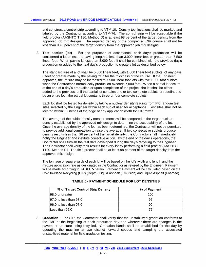
Cape seal treatment will be measured and paid for according to the appropriate asphalt surface treatment and emulsified asphalt slurry seal pay items and pay units specified in the Contract to complete the work. 10-21-14; Reissued 7-12-16_(SPCN)
TOC , VDOT Web , OVDOT , I , II , III , IV , V , VI , VII , VIII , 2018 Supplement , 2016 Spec Book
3-11
cq312-000110-00
GUIDELINES – For Richmond district projects with emulsified asphalt slurry seal. {2007-cu312000a}
VACUUMING EMULSIFIED ASPHALT SLURRY SEALS
The Special Provision for EMULSIFIED ASPHALT SLURRY SEAL (SP312-000100-00) is amended as follows:
Section IV. C. Application is amended to include the following as the third paragraph:
All routes receiving an Emulsified Asphalt Slurry Seal or a Cape Seal (Modified Single Seal or Modified Double Seal with Slurry Seal) shall be lightly broomed to remove loose aggregate prior to opening the pavement surface to traffic. All excess aggregate material on the pavement surface travel lane(s) and accumulated along curb and gutter sections, the edge of pavement/lawns, and hard-surfaced driveway entrances shall be removed by mobile vacuum unit after either final or interim riding surface has been opened to traffic as directed by the Engineer up to three weeks after pavement surface has been opened to traffic.
TOC , VDOT Web , OVDOT , I , II , III , IV , V , VI , VII , VIII , 2018 Supplement , 2016 Spec Book
3-12
cq314-000100-00
GUIDELINES – For Richmond district projects with asphalt surface treatment. {2007-cu314000a}
VACUUMING ASPHALT SURFACE TREATMENTS
The Special Provision for ASPHALT SURFACE TREATMENT (SP314-000100-00) is amended as follows:
Section IV. (b) Modified Single Seal and Modified Double Seal Treatments is amended to include the following as the third paragraph:
All routes receiving an Asphalt Surface Treatment (Modified Single Seal or Modified Double Seal) shall be lightly broomed to remove loose aggregate prior to opening the pavement surface to traffic. All excess aggregate material on the pavement surface travel lane(s), and accumulated along curb and gutter sections, the edge of pavement/lawns, and hard-surfaced driveway entrances shall be removed by mobile vacuum unit after surface treatment has been exposed to traffic as directed by the Engineer up to three weeks after final treatment has been opened to traffic.
Section VI. - Measurement and Payment is amended to include the following:
Vacuuming shall be included in the price of other appropriate items. 9-4-14; Reissued 7-12-16_(SPCN)
TOC , VDOT Web , OVDOT , I , II , III , IV , V , VI , VII , VIII , 2018 Supplement , 2016 Spec Book
3-13
cq315-070100-02
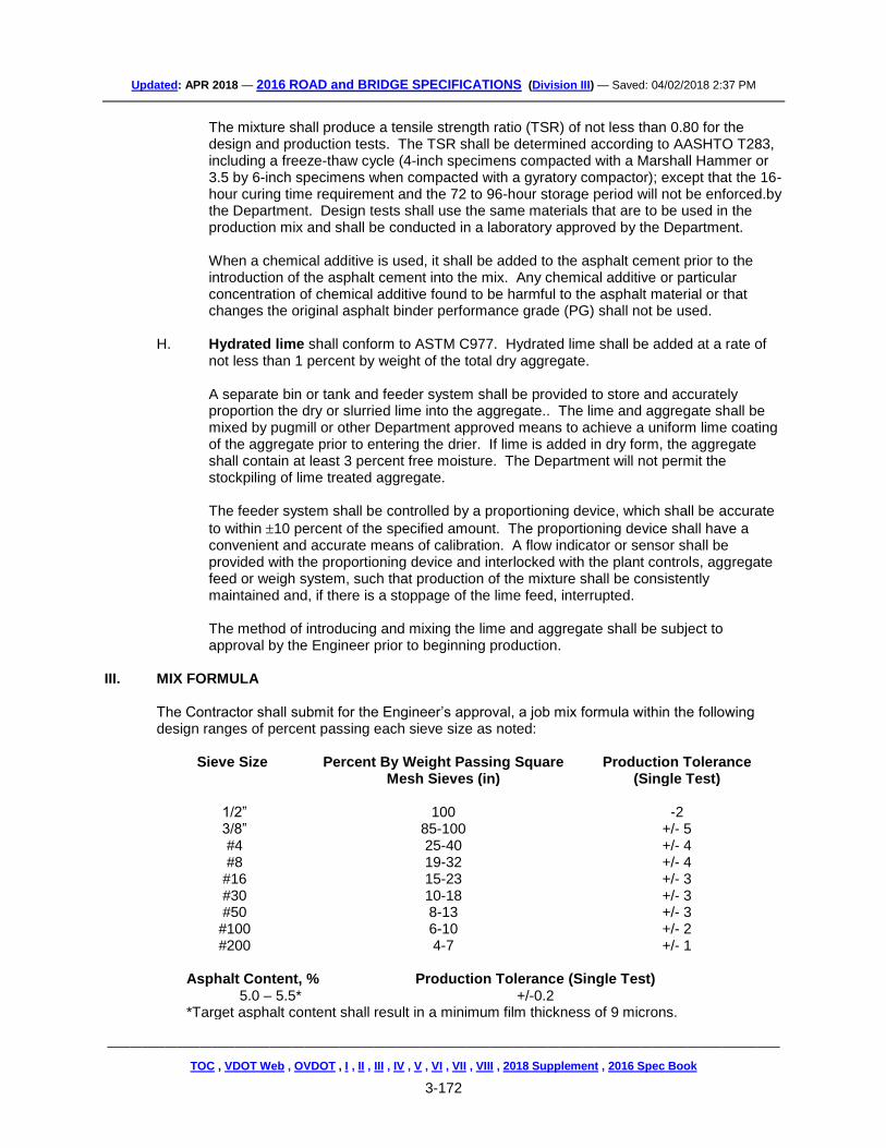
GUIDELINES – Asphalt projects where “Thin Hot Mix Asphalt Concrete Overlay” is used and “Rideability” applies (plant mix only). {2007-cu315000a}
RIDEABILITY FOR THIN HOT MIX ASPHALT CONCRETE OVERLAY (THMACO –— The Special Provision for RIDEABILITY (For Asphalt Concrete Pavement) is amended as follows:
The the exception to rideabiity testing for “scratch courses” (THMACO) specified in Section II-1B Single-Lift Construction will not apply to pavements designated in the Contract for rideabiity testing. Rideabiity shall be performed as with an asphalt concrete (AC) layer.
TOC , VDOT Web , OVDOT , I , II , III , IV , V , VI , VII , VIII , 2018 Supplement , 2016 Spec Book
3-14
cq315-070110-01
GUIDELINES – Asphalt projects where “Rideability” with incentive only adjustments apply (plant mix only).
RIDEABILITY FOR ASPHALT CONCRETE PAVEMENT (INCENTIVE ONLY –— The Special Provision for RIDEABILITY (For Asphalt Concrete Pavement) is amended as follows:
This project is designated as “incentive only” in accordance Section II-2 Incentive Only Projects.
TOC , VDOT Web , OVDOT , I , II , III , IV , V , VI , VII , VIII , 2018 Supplement , 2016 Spec Book
3-15
GUIDELINES — For projects that allow existing pavement to be open cut. Include in the proposal: SP314-000110-00or SP314-000100-00. {2007-S302B00}
SP302-000100-00
VIRGINIA DEPARTMENT OF TRANSPORTATION SPECIAL PROVISION FOR
RESTORING EXISTING PAVEMENT
July 12, 2016 I. DESCRIPTION
This work shall consist of restoring existing pavement, removed for installation or repair of utilities such as, but not limited to pipe culverts, conduits, water and sanitary sewer items.
II. MATERIALS Asphalt Concrete shall conform to Section 211 of the Specifications. Aggregate Subbase material shall conform to Section 208 of the Specifications. Asphalt Material shall conform to Section 210 of the Specifications. Fine Aggregate shall conform to Section 202 of the Specifications. Coarse Aggregate for surface treatment shall conform to Section 203 of the Specifications. Hydraulic Cement Concrete Class A3 shall conform to Section 217 of the Specifications. Steel Reinforcement shall conform to Section 223 of the Specifications.
III. PROCEDURES Pavement restoration shall be according to this Provision and plan notes. Backfill shall be according to Section 302.03(a)2.g. of the Specifications. Asphalt Concrete shall be placed and compacted according to Section 315 of the Specifications. Surface Treatment shall be placed according to the special provision for Asphalt Surface Treatment and the attached drawing. Concrete Pavement shall be placed according to the special provision for Patching Hydraulic Cement Concrete Pavement and this special provision. Open trench in Hydraulic Cement Concrete Pavement should be located at existing transverse joints if at all possible. If concrete pavement is removed within two feet of an existing transverse joint, pavement removal shall be extended two feet beyond the joint. Reinforcing steel and dowels shall be installed according to Road and Bridge Standard PR-2. Joint replacement shall be according to Road and Bridge Standard PR-2.
TOC , VDOT Web , OVDOT , I , II , III , IV , V , VI , VII , VIII , 2018 Supplement , 2016 Spec Book
3-16
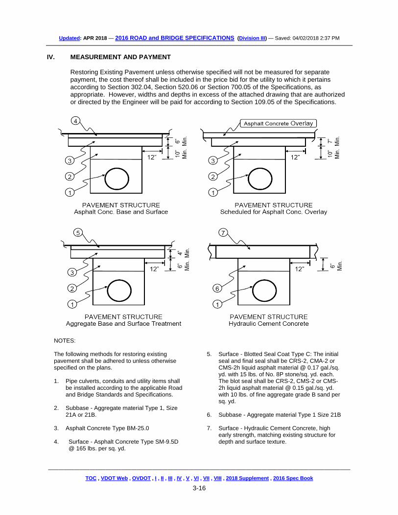
IV. MEASUREMENT AND PAYMENT Restoring Existing Pavement unless otherwise specified will not be measured for separate payment, the cost thereof shall be included in the price bid for the utility to which it pertains according to Section 302.04, Section 520.06 or Section 700.05 of the Specifications, as appropriate. However, widths and depths in excess of the attached drawing that are authorized or directed by the Engineer will be paid for according to Section 109.05 of the Specifications.
NOTES: The following methods for restoring existing pavement shall be adhered to unless otherwise specified on the plans. 1. Pipe culverts, conduits and utility items shall
be installed according to the applicable Road and Bridge Standards and Specifications.
2. Subbase - Aggregate material Type 1, Size
21A or 21B. 3. Asphalt Concrete Type BM-25.0 4. Surface - Asphalt Concrete Type SM-9.5D
@ 165 lbs. per sq. yd.
5. Surface - Blotted Seal Coat Type C: The initial
seal and final seal shall be CRS-2, CMA-2 or CMS-2h liquid asphalt material @ 0.17 gal./sq. yd. with 15 lbs. of No. 8P stone/sq. yd. each. The blot seal shall be CRS-2, CMS-2 or CMS-2h liquid asphalt material @ 0.15 gal./sq. yd. with 10 lbs. of fine aggregate grade B sand per sq. yd.
6. Subbase - Aggregate material Type 1 Size 21B 7. Surface - Hydraulic Cement Concrete, high
early strength, matching existing structure for depth and surface texture.
TOC , VDOT Web , OVDOT , I , II , III , IV , V , VI , VII , VIII , 2018 Supplement , 2016 Spec Book
3-17
GUIDELINES — For projects with watercourses that have to be functionally preserved and yet allow vehicular traffic (including construction vehicles) to cross. {2007-S302H01}
SP302-000110-00
VIRGINIA DEPARTMENT OF TRANSPORTATION
SPECIAL PROVISION FOR TEMPORARY VEHICULAR WATERCOURSE CROSSING
March 25, 2009; Reissued 7-12-16
I. GENERAL
This work shall consist of constructing a temporary vehicular watercourse crossing according to these specifications and in conformity with the plans, Standard Drawings, permits and Contract documents.
II. MATERIALS Pipe shall conform to Section 232 of the Specifications. Class I Dry Riprap shall conform to Section 204.02 (b) of the Specifications. Number 1 coarse aggregate shall conform to Section 203 of the Specifications. Geotextile Bedding Material shall conform to Section 245 of the Specifications. Timber shall be structural grade material conforming to Section 236 of the Specifications.
III. CONSTRUCTION The Contractor shall construct the temporary vehicular watercourse crossing at right angle to the stream. Where approach conditions dictate, the crossing may vary 15 degrees from a line drawn perpendicular to the approximate centerline of the stream. The finished grade elevation of the crossing shall be 3 feet above the ordinary high water elevation. When not specified in the plans, or elsewhere in the Contract, the Contractor shall determine the ordinary high water elevation using appropriate methods, and submit this information to the Engineer for approval prior to commencement of construction of the crossing. Clearing and excavation of the stream bed and banks shall be kept to a minimum. The installation and removal of the crossing shall be accomplished in the dry utilizing a dry pump around or a stream diversion. The Engineer may make minor adjustments in the location of any temporary vehicular watercourse crossing identified in the construction plans provided that the adjustment does not change the design for the temporary vehicular watercourse crossing or impact the environmental permits. In the event that the modifications are not covered by the permit, the Contractor shall be responsible for providing the information necessary for VDOT to secure the required permit modification. All temporary vehicular watercourse crossings will require a water quality permit. Inlet and outlet ends of culverts greater than 24 inches in diameter shall be countersunk a minimum of 6 inches below the natural stream bed. Inlet and outlet ends of culverts 24 inches or less in
TOC , VDOT Web , OVDOT , I , II , III , IV , V , VI , VII , VIII , 2018 Supplement , 2016 Spec Book
3-18
diameter shall be countersunk a minimum of 3 inches below the natural stream bed. If bedrock is encountered during installation or if steep slopes prohibit countersinking to the prescribed depth, then the work shall cease and the Contractor shall notify the Engineer. Geotextile bedding material shall be placed on the stream bed and stream banks prior to installation of the culverts and aggregate. The geotextile bedding material shall cover the stream bed and extend a minimum of one foot beyond the end of the culverts and rip rap material. The culverts shall extend a minimum of one foot beyond the upstream and downstream toe of the aggregate placed around the culvert. Timbers used for temporary vehicular watercourse crossing shall be 12-inch x 12-inch timbers and shall be anchored sufficiently to prevent displacement during use or storm events. The Contractor shall maintain the temporary vehicular watercourse crossing until no longer needed. When no longer needed, all material associated with the temporary vehicular watercourse crossing shall be removed in their entirety and the stream bed and stream banks restored to their previous elevations. Stream banks shall be reseeded and seed bed protected by the use of geotextile embankment stabilization fabric conforming to Section 245.03(d) of the Specifications.
IV. MEASUREMENT AND PAYMENT
Temporary Vehicular Watercourse Crossing will be measured and paid for on an each basis per location. This price shall include full compensation for furnishing and installing all materials including pipe, aggregate riprap, geotextile bedding material, timbers, providing pump around or stream diversion during construction and removal, and all labor, equipment, materials, and incidentals needed for construction, maintenance, and removal and disposal of the crossing when no longer required. Payment will be made under: Pay Item Pay Unit
TOC , VDOT Web , OVDOT , I , II , III , IV , V , VI , VII , VIII , 2018 Supplement , 2016 Spec Book
3-19
GUIDELINES - For use on all projects using the Jack-and-Bore method of pipe installation.
SP302-000120-00
VIRGINIA DEPARTMENT OF TRANSPORTATION SPECIAL PROVISION FOR
JACK AND BORE
October 27, 2016 I. DESCRIPTION
The work covered by this section consists of providing all labor, materials, and equipment, and performing all operations required for installing the specified diameters of culvert or utility casing pipe by the jack and bore method in accordance with the requirements of the Contract documents at the locations, alignments and grades shown on the plans. This work shall also include the removal of obstructions, if encountered, in a controlled manner while maintaining face stability and avoiding loss of ground. This special provision supplements Section 302.03(a)1 of the current VDOT Road and Bridge Specifications.
Prior to bidding, the Contractor shall visit and examine the work site and all conditions thereon and take into consideration all such conditions that may affect this work. Subsurface data for the project is available for review at the District Materials Office.
II. QUALIFICATIONS
The Contractor shall be experienced in jack and bore operations and have completed a minimum of five jack and bore projects in similar ground and groundwater conditions with similar cover conditions using similar size, type, and length of pipes to be installed on this project within the last three years.
The Contractor shall furnish to the Engineer a listing of the required information including contact personnel and their current phone numbers. The Contractor shall furnish the name and experience record of the field supervisor who will be in daily responsible charge of the jack and bore operation as well as the operator for each shift. The field supervisor will be present at all times when the work is being progressed. Qualified work crew personnel shall each have a minimum of three years’ experience with jack and bore equipment similar to that proposed for this project and in similar ground and cover conditions.
III. SUBMITTALS
The Contractor shall submit five copies of the following material to the Engineer for review and acceptance at least 30 calendar days prior to beginning jack and bore construction:
1. Shop drawings and narratives describing proposed pipe jack and bore means and methods including the following: equipment, equipment layout, procedures, sequence and production schedule. For boring equipment, show design, dimensions, method of operation, and steering control capability.
2. Description of proposed line and grade control methods.
TOC , VDOT Web , OVDOT , I , II , III , IV , V , VI , VII , VIII , 2018 Supplement , 2016 Spec Book
3-20
3. Proposed procedures, materials, and equipment for lubricating the exterior of the pipe during jacking.
4. Proposed procedures, materials, and equipment for removing, clearing or otherwise making it possible to advance past obstructions.
5. Proposed procedures, materials, and equipment to fill voids outside of the pipe created or detected during the advance of the pipe.
6. Calculations, prepared and stamped by a Registered Professional Engineer licensed in the Commonwealth of Virginia, that demonstrate the pipe to be jacked has been designed to support the maximum anticipated earth loads and superimposed live loads, including but not limited to jacking loads, that may be imposed on the pipe during and after construction. The Contractor shall determine the additional stresses imposed on the pipe during jacking operations and upgrade the quality and strength of the pipe and pipe joints to the extent necessary to withstand the additional stresses imposed by the jacking operation or change his methodology to account for additional loads and stresses.
7. Blank daily log of jack and bore progress, to be completed within 8 hours of the completion of each shift to document the jack and bore work accomplished, the amount of excavated soil, and the results of ground surface survey monitoring.
8. Description of method to remove and dispose of spoil.
9. Estimate of anticipated jacking loads.
10. Pit dimensions, locations, surface construction, profile, depth, method of excavation, shoring bracing and thrust block design, including drawings and complete calculations.
11. Plan for flood protection and dewatering of pits and tunnel structures during construction.
12. Verification that the pipe complies with applicable contract requirements.
13. Condition survey (photographs and ground survey) of existing surface conditions along the planned pipe alignments. Photographs at 100% coverage. Minimum ground survey at edges of pavement and centerline of each travel direction (along pipe alignment), and at pipe centerline and 10-foot offsets (perpendicular to pipe alignment).
14. A detailed plan for monitoring ground surface movement due to the jack and bore operation. The plan shall address the method and frequency of survey measurement. At a minimum, the plan shall include taking measurements of ground movements of all structures, roadways, and any other areas of concern within at least 25 feet on both sides of all jack and bore pipelines at a maximum spacing of 100 feet along the jack and bore route or as otherwise required by the Engineer. The Contractor shall submit initial survey readings prior to start of jack and bore operations. The plan shall include survey readings of surface monitoring points daily during active boring operations. Subsequent readings shall be performed a minimum of one week, two weeks, and four weeks after completion of jack and bore operations and at project completion.
15. Contingency plans for review and acceptance for the following potential conditions: Damage to the pipeline structural integrity and repair, loss and return to line and grade, and loss of ground.
16. Contingency plan also required for encountering obstructions. Details of proposed means and methods for obstruction removal are required along the alignment with consideration of possible
TOC , VDOT Web , OVDOT , I , II , III , IV , V , VI , VII , VIII , 2018 Supplement , 2016 Spec Book
3-21
constraints on surface access, including but not limited to the use of recovery shafts. Recovery shafts shall be constructed in accordance with submittals approved by the Engineer.
17. Verification that procedures meet all applicable OSHA requirements. These procedures shall be submitted for record purposes only and will not be subject to approval by the Engineer. As a minimum, the following should be included: Protection against soil instability and ground water inflow; safety for shaft access and exit; protection against mechanical and hydraulic equipment operations and for lifting and hoisting equipment and material; ventilation and lighting; monitoring for hazardous gases; protection against flooding and means for emergency evacuation; protection of shaft; emergency protection equipment; and safety supervisory responsibilities.
18. As-built plans of all jack and bore elements within 30 calendar days of project completion. As-built plans shall include details of the installed pipes, temporary works, permanent structures, backfill materials, post-construction surveys, construction photographs, descriptions of problems encountered, and corrective procedures implemented.
IV. EQUIPMENT AND MATERIALS
1. Pipe shall meet the following minimum requirements:
A. For culvert installations, the pipe shall be made of reinforced concrete in accordance with ASTM C76. For utility installations, the pipe shall be made of steel (ASTM A139), 0.5 inches minimum wall thickness, shall be round, with a smooth, even outer surface and shall have joints that allow for easy butt-welded connections between pipe sections. Other pipe types may only be used if approved by the Engineer.
B. Pipe ends shall be square and smooth so that the jacking loads are evenly distributed around the entire pipe joint to minimize point loads when the pipe is jacked.
C. The pipe shall be capable of withstanding the jacking forces that will be imposed by the process of installation.
D. The driving ends of the pipe and intermediate joints shall be protected against damage.
E. The detailed method proposed to cushion and distribute the jacking forces shall be submitted to the Engineer for review and acceptance.
F. Any pipe showing signs of failure shall be jacked through to the reception shaft, removed and replaced at no additional cost to the Engineer.
G. The pipe manufacturer’s design jacking loads shall not be exceeded during the installation process. The pipe shall be designed to withstand all temporary installation loads.
2. Jacking equipment shall meet the following minimum requirements:
A. The thrust blocks shall be designed to transfer jacking loads into the soil and support the maximum pressure developed by the main jacking system with a minimum factor of safety of 2.5. The thrust blocks shall be perpendicular to the pipe alignment. Special care shall be taken when setting the pipe guide rails in the jacking pit to ensure correctness of the alignment, grade, and stability. If concrete thrust blocks or a treated soil zone are utilized to transfer jacking loads into the soil, the casing shall not be jacked until the concrete or treated soil have attained the required design strength.
TOC , VDOT Web , OVDOT , I , II , III , IV , V , VI , VII , VIII , 2018 Supplement , 2016 Spec Book
3-22
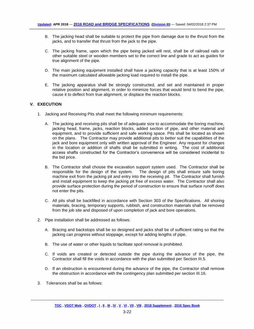
B. The jacking head shall be suitable to protect the pipe from damage due to the thrust from the jacks, and to transfer that thrust from the jack to the pipe.
C. The jacking frame, upon which the pipe being jacked will rest, shall be of railroad rails or other suitable steel or wooden members set to the correct line and grade to act as guides for true alignment of the pipe.
D. The main jacking equipment installed shall have a jacking capacity that is at least 150% of the maximum calculated allowable jacking load required to install the pipe.
E. The jacking apparatus shall be strongly constructed, and set and maintained in proper relative position and alignment, in order to minimize forces that would tend to bend the pipe, cause it to deflect from true alignment, or displace the reaction blocks.
V. EXECUTION
1. Jacking and Receiving Pits shall meet the following minimum requirements:
A. The jacking and receiving pits shall be of adequate size to accommodate the boring machine, jacking head, frame, jacks, reaction blocks, added section of pipe, and other material and equipment, and to provide sufficient and safe working space. Pits shall be located as shown on the plans. The Contractor may provide additional pits to better suit the capabilities of the jack and bore equipment only with written approval of the Engineer. Any request for changes in the location or addition of shafts shall be submitted in writing. The cost of additional access shafts constructed for the Contractor’s convenience will be considered incidental to the bid price.
B. The Contractor shall choose the excavation support system used. The Contractor shall be responsible for the design of the system. The design of pits shall ensure safe boring machine exit from the jacking pit and entry into the receiving pit. The Contractor shall furnish and install equipment to keep the jacking pit free of excess water. The Contractor shall also provide surface protection during the period of construction to ensure that surface runoff does not enter the pits.
C. All pits shall be backfilled in accordance with Section 303 of the Specifications. All shoring materials, bracing, temporary supports, rubbish, and construction materials shall be removed from the job site and disposed of upon completion of jack and bore operations.
2. Pipe installation shall be addressed as follows:
A. Bracing and backstops shall be so designed and jacks shall be of sufficient rating so that the jacking can progress without stoppage, except for adding lengths of pipe.
B. The use of water or other liquids to facilitate spoil removal is prohibited.
C. If voids are created or detected outside the pipe during the advance of the pipe, the Contractor shall fill the voids in accordance with the plan submitted per Section III.5.
D. If an obstruction is encountered during the advance of the pipe, the Contractor shall remove the obstruction in accordance with the contingency plan submitted per section III.16.
TOC , VDOT Web , OVDOT , I , II , III , IV , V , VI , VII , VIII , 2018 Supplement , 2016 Spec Book
3-23
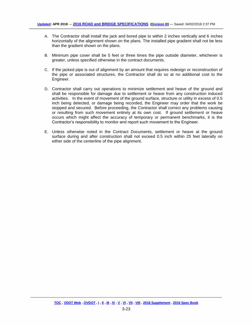
A. The Contractor shall install the jack and bored pipe to within 2 inches vertically and 6 inches horizontally of the alignment shown on the plans. The installed pipe gradient shall not be less than the gradient shown on the plans.
B. Minimum pipe cover shall be 5 feet or three times the pipe outside diameter, whichever is greater, unless specified otherwise in the contract documents.
C. If the jacked pipe is out of alignment by an amount that requires redesign or reconstruction of the pipe or associated structures, the Contractor shall do so at no additional cost to the Engineer.
D. Contractor shall carry out operations to minimize settlement and heave of the ground and shall be responsible for damage due to settlement or heave from any construction induced activities. In the event of movement of the ground surface, structure or utility in excess of 0.5 inch being detected, or damage being recorded, the Engineer may order that the work be stopped and secured. Before proceeding, the Contractor shall correct any problems causing or resulting from such movement entirely at its own cost. If ground settlement or heave occurs which might affect the accuracy of temporary or permanent benchmarks, it is the Contractor’s responsibility to monitor and report such movement to the Engineer.
E. Unless otherwise noted in the Contract Documents, settlement or heave at the ground surface during and after construction shall not exceed 0.5 inch within 25 feet laterally on either side of the centerline of the pipe alignment.
TOC , VDOT Web , OVDOT , I , II , III , IV , V , VI , VII , VIII , 2018 Supplement , 2016 Spec Book
3-24
GUIDELINES - For pipe installed directly behind a microtunneling boring machine (MTBM).
SP302-000130-00
VIRGINIA DEPARTMENT OF TRANSPORTATION SPECIAL PROVISION FOR
MICROTUNNELING November 1, 2016
VI. DESCRIPTION
The work covered by this section consists of providing all labor, materials, and equipment, and performing all operations required for installing the specified diameters of pipe by the microtunneling method where the pipe is installed directly behind the microtunneling boring machine (MTBM), in accordance with the requirements of the Contract at the locations, alignments and grades shown on the Plans. Only reinforced concrete pipe (RCP) or steel pipe shall be installed directly unless other pipe types are approved for direct installation by the Engineer. All other pipe types shall be installed within steel casing pipe. Steel casing pipe shall not be used as the final drainage pipe. Subsurface data for the project is available for review at the District Materials Office.
VII. QUALIFICATIONS
The Contractor shall be experienced in microtunneling and have completed a minimum of five pipeline or conduit construction projects in similar ground and ground water conditions with similar cover conditions below an interstate or four-lane divided highway within the last three years.
The Contractor shall furnish to the Engineer a listing of the required information including contact personnel and their current phone numbers. The Contractor shall furnish the name and experience record of the microtunneling foreman or supervisor who will be in daily responsible charge of the microtunneling operation as well as the MTBM operator for each shift. Qualified work crew personnel shall each have a minimum of 3000 linear feet and ten drives operating microtunneling equipment similar to that proposed for this particular work and in similar ground and cover conditions.
VIII. SUBMITTALS
The Contractor shall submit five copies of the following material to the Engineer for review and acceptance at least 30 calendar days prior to beginning microtunneling construction:
19. Personnel: Documentation summarizing the pre-qualifications of key personnel and the financial stability of the company.
20. Equipment: Manufacturer’s literature describing, in detail, the MTBM and ancillary systems to be used including complete description and details of guidance systems and method of grade and alignment adjustments.
21. Descriptions of similar projects including names, addresses and phone numbers of owner’s representatives on which this similar system by the same manufacturer has been successfully used.
22. Description of method to remove and dispose of spoil.
TOC , VDOT Web , OVDOT , I , II , III , IV , V , VI , VII , VIII , 2018 Supplement , 2016 Spec Book
3-25
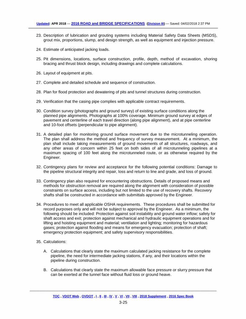
23. Description of lubrication and grouting systems including Material Safety Data Sheets (MSDS), grout mix, proportions, slump, and design strength, as well as equipment and injection pressure.
24. Estimate of anticipated jacking loads.
25. Pit dimensions, locations, surface construction, profile, depth, method of excavation, shoring bracing and thrust block design, including drawings and complete calculations.
26. Layout of equipment at pits.
27. Complete and detailed schedule and sequence of construction.
28. Plan for flood protection and dewatering of pits and tunnel structures during construction.
29. Verification that the casing pipe complies with applicable contract requirements.
30. Condition survey (photographs and ground survey) of existing surface conditions along the planned pipe alignments. Photographs at 100% coverage. Minimum ground survey at edges of pavement and centerline of each travel direction (along pipe alignment), and at pipe centerline and 10-foot offsets (perpendicular to pipe alignment).
31. A detailed plan for monitoring ground surface movement due to the microtunneling operation. The plan shall address the method and frequency of survey measurement. At a minimum, the plan shall include taking measurements of ground movements of all structures, roadways, and any other areas of concern within 25 feet on both sides of all microtunneling pipelines at a maximum spacing of 100 feet along the microtunneled route, or as otherwise required by the Engineer.
32. Contingency plans for review and acceptance for the following potential conditions: Damage to the pipeline structural integrity and repair, loss and return to line and grade, and loss of ground.
33. Contingency plan also required for encountering obstructions. Details of proposed means and methods for obstruction removal are required along the alignment with consideration of possible constraints on surface access, including but not limited to the use of recovery shafts. Recovery shafts shall be constructed in accordance with submittals approved by the Engineer.
34. Procedures to meet all applicable OSHA requirements. These procedures shall be submitted for record purposes only and will not be subject to approval by the Engineer. As a minimum, the following should be included: Protection against soil instability and ground water inflow; safety for shaft access and exit; protection against mechanical and hydraulic equipment operations and for lifting and hoisting equipment and material; ventilation and lighting; monitoring for hazardous gases; protection against flooding and means for emergency evacuation; protection of shaft; emergency protection equipment; and safety supervisory responsibilities.
35. Calculations:
A. Calculations that clearly state the maximum calculated jacking resistance for the complete pipeline, the need for intermediate jacking stations, if any, and their locations within the pipeline during construction.
B. Calculations that clearly state the maximum allowable face pressure or slurry pressure that can be exerted at the tunnel face without fluid loss or ground heave.
TOC , VDOT Web , OVDOT , I , II , III , IV , V , VI , VII , VIII , 2018 Supplement , 2016 Spec Book
3-26
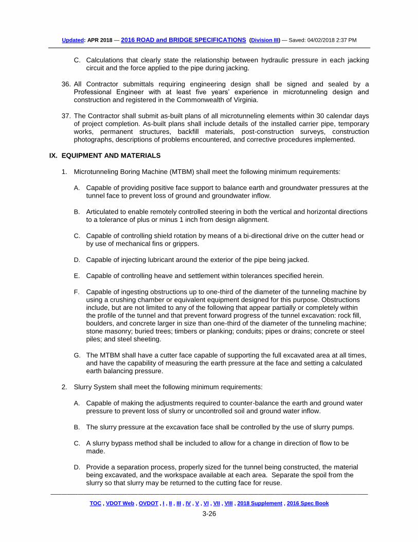
C. Calculations that clearly state the relationship between hydraulic pressure in each jacking circuit and the force applied to the pipe during jacking.
36. All Contractor submittals requiring engineering design shall be signed and sealed by a Professional Engineer with at least five years’ experience in microtunneling design and construction and registered in the Commonwealth of Virginia.
37. The Contractor shall submit as-built plans of all microtunneling elements within 30 calendar days of project completion. As-built plans shall include details of the installed carrier pipe, temporary works, permanent structures, backfill materials, post-construction surveys, construction photographs, descriptions of problems encountered, and corrective procedures implemented.
IX. EQUIPMENT AND MATERIALS
1. Microtunneling Boring Machine (MTBM) shall meet the following minimum requirements:
A. Capable of providing positive face support to balance earth and groundwater pressures at the tunnel face to prevent loss of ground and groundwater inflow.
B. Articulated to enable remotely controlled steering in both the vertical and horizontal directions to a tolerance of plus or minus 1 inch from design alignment.
C. Capable of controlling shield rotation by means of a bi-directional drive on the cutter head or by use of mechanical fins or grippers.
D. Capable of injecting lubricant around the exterior of the pipe being jacked.
E. Capable of controlling heave and settlement within tolerances specified herein.
F. Capable of ingesting obstructions up to one-third of the diameter of the tunneling machine by using a crushing chamber or equivalent equipment designed for this purpose. Obstructions include, but are not limited to any of the following that appear partially or completely within the profile of the tunnel and that prevent forward progress of the tunnel excavation: rock fill, boulders, and concrete larger in size than one-third of the diameter of the tunneling machine; stone masonry; buried trees; timbers or planking; conduits; pipes or drains; concrete or steel piles; and steel sheeting.
G. The MTBM shall have a cutter face capable of supporting the full excavated area at all times, and have the capability of measuring the earth pressure at the face and setting a calculated earth balancing pressure.
2. Slurry System shall meet the following minimum requirements:
A. Capable of making the adjustments required to counter-balance the earth and ground water pressure to prevent loss of slurry or uncontrolled soil and ground water inflow.
B. The slurry pressure at the excavation face shall be controlled by the use of slurry pumps.
C. A slurry bypass method shall be included to allow for a change in direction of flow to be made.
D. Provide a separation process, properly sized for the tunnel being constructed, the material being excavated, and the workspace available at each area. Separate the spoil from the slurry so that slurry may be returned to the cutting face for reuse.
TOC , VDOT Web , OVDOT , I , II , III , IV , V , VI , VII , VIII , 2018 Supplement , 2016 Spec Book
3-27
E. Monitor the composition of the slurry to maintain the slurry density and viscosity limits as accepted in the submittal.
3. Jacking System shall meet the following minimum requirements: A. The main jacking equipment installed shall have a jacking capacity that is at least 150% of
the maximum calculated allowable jacking load required to install the pipe.
B. The jacking system shall develop a uniform distribution of jacking forces on the end of the pipe by the use of thruster rings and cushioning material.
C. A pipe lubrication system shall be utilized and fluid shall be circulated continuously throughout the tunneling operation. An approved lubricant shall be injected at the rear of the MTBM to lower the friction developed on the surface of the pipe during jacking.
D. The pipe lubrication system pressure shall be continuously monitored, recorded, and controlled to prevent pipe buckling, ground heave and migration of fluid to the surface or adjacent structures.
4. Thrust Blocks shall meet the following minimum requirements:
A. The thrust blocks shall be designed to transfer jacking loads into the earth and support the maximum pressure developed by the main jacking system with a minimum factor of safety of 2.5.
B. The thrust blocks shall be perpendicular to the pipe alignment.
C. If concrete thrust blocks or a treated soil zone are used to transfer jacking loads into the soil, the MTBM shall not be jacked until the concrete or other materials have attained the required strength.
5. Excavation Controls shall meet the following minimum requirements:
A. The control equipment shall integrate the method of excavation and the removal of soil and its simultaneous replacement by the pipe.
B. The control system shall synchronize spoils removal, excavation and jacking speeds as each pipe section is jacked forward.
C. Operations shall be stopped when they result in pipe damage or surface disruption. The Contractor shall propose, for the review of the Engineer, immediate action to remedy the problem. If acceptable to the Engineer, such action shall be at no additional cost to the Department.
6. Remote Steering Controls shall provide the following minimum information to the operator:
A. Any deviation of the MTBM from the required line and grade of the carrier pipe by reference to a laser beam.
TOC , VDOT Web , OVDOT , I , II , III , IV , V , VI , VII , VIII , 2018 Supplement , 2016 Spec Book
3-28
E. Instantaneous jacking rate and total distance jacked.
F. Indication of steering direction.
G. The volume of slurry flow in both the supply and return side of the slurry loop.
H. Indication of slurry bypass valve position.
I. Indication of pressure of the slurry in the slurry chamber.
7. Guidance and Monitoring Equipment shall meet the following minimum requirements:
A. Display equipment shall show and record the position of the shield with respect to the design line and grade. Line and grade tolerances of the pipe shall be 1 inch on line between the shafts. A return to line and grade shall be 1 inch in 25 feet.
8. Pipe shall meet the following minimum requirements:
A. Steel pipe (min. ASTM A139, Grade B) shall be 0.5-in minimum wall thickness, shall be round with a smooth, even outer surface and shall have joints that allow for easy butt-welded connections between pipes.
B. Pipe ends shall be square and smooth so that the jacking loads are evenly distributed around the entire pipe joint to minimize point loads when the pipe is jacked.
C. The pipe shall be capable of withstanding the jacking forces that will be imposed by the process of installation.
D. The driving ends of the pipe and intermediate joints shall be protected against damage.
E. The detailed method proposed to cushion and distribute the jacking forces shall be submitted to the Engineer for review and acceptance.
F. Any pipe showing signs of failure shall be jacked through to the reception shaft, removed and replaced at no additional cost to the Department.
G. The pipe manufacturer’s design jacking loads shall not be exceeded during the installation process. The pipe shall be designed to withstand all temporary installation loads.
X. EXECUTION
1. Grouting shall meet the following minimum requirements:
A. The annular space created by the over cut of the MTBM shall be filled with pressure-injected grout or other material approved by the Engineer immediately after completion of the tunneling operation. The Contractor shall promptly clean up and properly remove any spillage.
B. The pressure-injected grout or other approved material shall fill voids outside the limits of the excavation created by caving or collapse of earth cover over the excavation.
C. The Contractor shall furnish and operate suitable equipment for any required grouting operations depending on the condition of the application. The grouting operation shall not damage adjacent utilities or other properties. Grout shall be injected at a pressure that will
TOC , VDOT Web , OVDOT , I , II , III , IV , V , VI , VII , VIII , 2018 Supplement , 2016 Spec Book
3-29
not distort or imperil any portion of the work or existing installations or structures.
2. Launching and Receiving Pits shall meet the following minimum requirements:
A. Launching and Receiving Pits shall be of a size commensurate with safe working practices and located approximately as shown on the Plans. The Contractor may provide additional shafts to better suit the capabilities of the microtunneling equipment proposed, only with written approval of the Engineer. Any request for changes in the location or addition of shafts shall be submitted in writing. The cost of additional access shafts constructed for the Contractor’s convenience will be considered incidental to the bid price.
B. The Contractor shall choose the excavation support system used. The Contractor shall be responsible for the design of the system. The design of pits and shafts shall ensure safe MTBM exit from the launching/driving/jacking pit and entry into the receiving pit. The Contractor shall furnish and install equipment to keep the jacking pit free of excess water. The Contractor shall also provide surface protection during the period of construction to ensure that surface runoff does not enter shafts. All pits shall be backfilled in accordance with Section 303 of the Specifications. All shoring materials, bracing, temporary supports, rubbish, and construction materials shall be removed from the job site and disposed of upon completion of microtunneling operations.
3. Obstructions shall be addressed as follows:
A. If the Contractor encounters an obstruction during the microtunneling procedure that stops the forward progress of the Work for greater than one hour, the Contractor shall immediately notify the Engineer. The Engineer shall verify that an obstruction has stopped the forward progress of the Work and shall authorize the Contractor to commence activities to be paid for under the appropriate payment item. Upon authorization by the Engineer, the Contractor shall proceed with removal of the obstruction. Payment for removal shall be from the start of removal operations (not including the first hour) until the successful removal of the obstruction. All work shall be performed in the presence of the Engineer.
B. If after four hours from the start of removal operations, the obstruction has not yet been removed by appropriate means and methods, further payment shall not be made under this provision. Compensation for obstruction removal efforts beyond four hours will be subject to a determination by the Engineer that a differing site condition exists in accordance with Section 104.03 of the Specifications.
4. Tolerances shall be as follows:
A. Pipelines shall be installed to within 1 inch of the vertical and 1 inch of the horizontal alignment shown on the plans.
B. Minimum pipe cover shall be 5 feet or three times the pipe outside diameter, whichever is greater, unless specified otherwise in the Contract.
C. Steering corrections made to the pipeline shall be carried out in such a manner that the joint-to-joint angle of any two adjacent pipes shall not exceed 0.5 degrees.
D. If the jacked pipeline is off design line or grade by an amount that requires redesign and construction of the pipeline or associated structure, the Contractor shall do so at no additional cost to the Engineer.
TOC , VDOT Web , OVDOT , I , II , III , IV , V , VI , VII , VIII , 2018 Supplement , 2016 Spec Book
3-30
E. Contractor shall carry out operations to minimize settlement or heave of the ground and shall be responsible for damage due to settlement or heave from any construction induced activities. In the event of movement of the ground surface, structure or utility being detected or damage recorded, the Engineer may order that the work be stopped and secured. Before proceeding, the Contractor shall correct any problems causing or resulting from such movement entirely at its own cost. If ground settlement or heave occurs that might affect the accuracy of temporary or permanent benchmarks, it is the Contractor’s responsibility to monitor and report such movement to the Engineer.
F. Unless otherwise noted in the Contract Documents, settlement or heave at the ground surface during and after construction shall not exceed 0.5 inch within 25 feet laterally on either side of the centerline of the pipe alignment. Over-cut shall not exceed 1 inch on the diameter of the pipe being installed, unless otherwise approved by the Engineer.
XI. MEASUREMENT AND PAYMENT
Microtunnel will be measured in units of linear feet to the nearest 0.1 feet for the diameter specified and will be paid for at the contract unit price per linear foot. This payment made will be full compensation for furnishing and installing the completed and accepted pipe for the diameter specified measured from the inside face of receiving pit to the inside face of launching/jacking pit; all equipment, tools, materials, incidentals and labor needed to complete the installation including grouting and lubricants; providing launching/jacking/receiving/recovery pits or supplemental shafts including excavation; disposal of material; design and construction of excavation support system; seal slab; dewatering; backfill and restoration of surface; ground surface monitoring; and all other work appurtenant to microtunneling and pipe installation. This payment will also include transportation and testing of the pipe.
All material removed from the microtunneling operation shall be assumed to be unsuitable and shall be disposed of offsite by the Contractor unless otherwise approved by the Engineer. The cost of removal and disposal of the unsuitable material will be included in the Contract unit price per linear foot of Microtunnel. In the event that the Engineer determines that the excavated material from the microtunneling operation is suitable for future roadway embankment use, the Contractor may, at his option, dispose of the material in a designated excess suitable material stockpile area approved by the Engineer. No additional compensation shall be paid to the Contractor for placing the excess material in the stockpile area.
Obstruction Removal, when authorized by the Engineer, shall be measured in hours and paid for at
the Contract unit price per hour based on the elapsed time from the start of obstruction removal to the successful removal of the obstruction, up to the limit of four hours. No measurement or payment will be made for removal of obstructions requiring an elapsed time of less than one hour or for which the Engineer has not granted approval for payment under this item in advance of performance of the work.
Payment will be made under:
Pay Item Pay Unit
Microtunnel (Diameter) Linear Foot Obstruction Removal Hour
TOC , VDOT Web , OVDOT , I , II , III , IV , V , VI , VII , VIII , 2018 Supplement , 2016 Spec Book
3-31
GUIDELINES - For use on all pipe rehabilitation projects. {2007-SU302001D}
SP302-000140-01
VIRGINIA DEPARTMENT OF TRANSPORTATION
SPECIAL PROVISION FOR PIPE REHABILITATION
November 7, 2016
I. DESCRIPTION
This work shall consist of the rehabilitation of existing storm water, surface water pipe culverts, and sanitary sewer lines by the method or methods specified at the designated locations described in the Contract in accordance with the requirements of this provision and as directed by the Engineer. All references to the AASHTO LRFD Bridge Design Specifications herein refer to the specific version in use by VDOT Structure and Bridge Division at the time of submittal.
II. MATERIALS - GENERAL REQUIREMENTS
1. Cement grout shall conform to Section 218.03(b) or (d) of the Specifications, or be a lightweight
cellular foamed concrete of at least 30 pcf unit weight and 100 psi 28-day compressive strength, with foaming agent meeting ASTM C869.
2. Method A pipe rehabilitation - Corrugated steel pipe used as pipe liners for Method A pipe
rehabilitation shall conform to Section 232.02 of the Specifications and shall be 10 gage with 3-inch by 1-inch angular corrugations. Corrugated steel pipe used as liners shall be manufactured by QC/QA producers on the VDOT Materials Division’s Approved Products List.
3. Method B pipe rehabilitation - Flexible pipe liners used for Method B pipe rehabilitation shall be
from the VDOT Materials Division’s Approved Products List, List No. 38. Liner systems may be subject to limitations for use as specified herein, by site-specific limitations for those locations listed in the Contract or as shown on the List No. 38 for the specific liner type. Where such is the case, the Contractor shall use only that type or those types that the Department has specified for the specific location listed in the Contract, and which are not limited by restrictions stated in List 38. The Contractor shall furnish the Engineer information, services, or other requirements as detailed in List 38 for all materials used for pipe rehabilitation systems specified in the Contract.
4. Method C pipe rehabilitation - Smooth-wall steel pipe used as liners used for Method C pipe
rehabilitation shall conform to Section 232.02(c)5 of the Specifications.
III. METHOD B LINER REQUIREMENTS
Method B pipe liners shall be one or more of the following categories as designated in the Contract: 1. Category A - Cured-In-Place Pipe (CIPP) - The Contractor shall submit design calculations
demonstrating the liner system conforms to the requirements of this Section.
The liner system shall conform to Drainage Manual, Chapter 8, Section 8.3.6.7 - Table A, “Flexible Liner (Method B) Type Selection Guidelines for Category A systems,” and shall follow ASTM F1216 Appendix X1.2.2, “Fully Deteriorated Gravity Pipe Conditions.” Design calculations shall provide groundwater table elevation at crown of pipe. Design calculations shall use a HL-93
TOC , VDOT Web , OVDOT , I , II , III , IV , V , VI , VII , VIII , 2018 Supplement , 2016 Spec Book
3-32
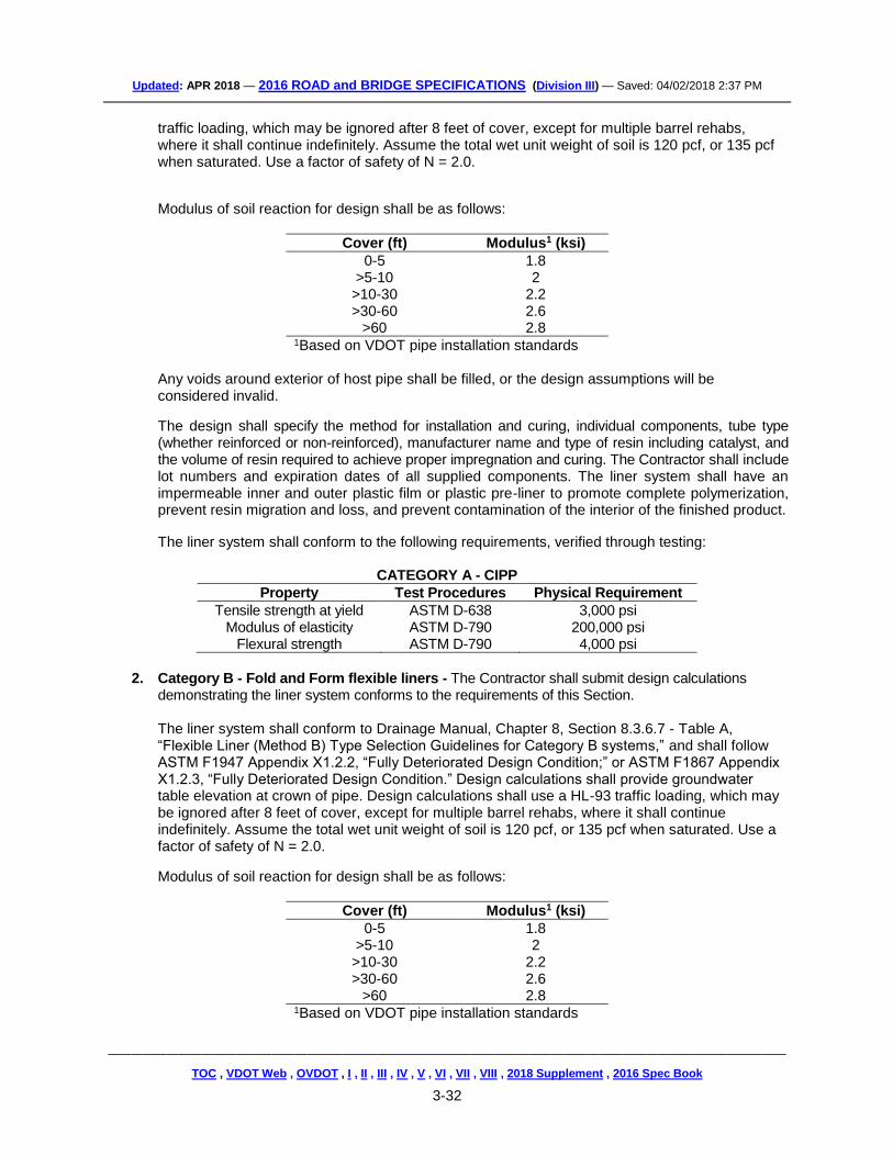
traffic loading, which may be ignored after 8 feet of cover, except for multiple barrel rehabs, where it shall continue indefinitely. Assume the total wet unit weight of soil is 120 pcf, or 135 pcf when saturated. Use a factor of safety of N = 2.0.
Modulus of soil reaction for design shall be as follows:
Cover (ft) Modulus1 (ksi)
0-5 1.8 >5-10 2 >10-30 2.2 >30-60 2.6
>60 2.8 1Based on VDOT pipe installation standards
Any voids around exterior of host pipe shall be filled, or the design assumptions will be considered invalid.
The design shall specify the method for installation and curing, individual components, tube type (whether reinforced or non-reinforced), manufacturer name and type of resin including catalyst, and the volume of resin required to achieve proper impregnation and curing. The Contractor shall include lot numbers and expiration dates of all supplied components. The liner system shall have an impermeable inner and outer plastic film or plastic pre-liner to promote complete polymerization, prevent resin migration and loss, and prevent contamination of the interior of the finished product.
The liner system shall conform to the following requirements, verified through testing:
CATEGORY A - CIPP
Property Test Procedures Physical Requirement
Tensile strength at yield ASTM D-638 3,000 psi Modulus of elasticity ASTM D-790 200,000 psi
Flexural strength ASTM D-790 4,000 psi
2. Category B - Fold and Form flexible liners - The Contractor shall submit design calculations
demonstrating the liner system conforms to the requirements of this Section.
The liner system shall conform to Drainage Manual, Chapter 8, Section 8.3.6.7 - Table A, “Flexible Liner (Method B) Type Selection Guidelines for Category B systems,” and shall follow ASTM F1947 Appendix X1.2.2, “Fully Deteriorated Design Condition;” or ASTM F1867 Appendix X1.2.3, “Fully Deteriorated Design Condition.” Design calculations shall provide groundwater table elevation at crown of pipe. Design calculations shall use a HL-93 traffic loading, which may be ignored after 8 feet of cover, except for multiple barrel rehabs, where it shall continue indefinitely. Assume the total wet unit weight of soil is 120 pcf, or 135 pcf when saturated. Use a factor of safety of N = 2.0.
Modulus of soil reaction for design shall be as follows:
Cover (ft) Modulus1 (ksi)
0-5 1.8 >5-10 2 >10-30 2.2 >30-60 2.6
>60 2.8 1Based on VDOT pipe installation standards
TOC , VDOT Web , OVDOT , I , II , III , IV , V , VI , VII , VIII , 2018 Supplement , 2016 Spec Book
3-33
Any voids around exterior of host pipe shall be filled, or design assumptions will be considered invalid.
3. Category C – High Density Polyethylene (HDPE), Polyvinylchloride (PVC) or
Polypropropylene (PP) Slip Liners – The Contractor shall submit design calculations demonstrating the liner system conforms to the requirements of this Section.
The liner system shall conform to Drainage Manual, Chapter 8, Section 8.3.6.7 - Table A, “Flexible Liner (Method B) Type Selection Guidelines for Category C systems,” and shall follow AASHTO LRFD Bridge Design Specifications, Section 12 . Spirally wound liners shall meet ASTM F1697 and F1741. The Contractor shall provide Standard Dimension Ratio (SDR) and outside diameter of pipe, for solid wall pipe; and outside diameter, inside diameter, diameter to centroid of wall, moment of inertia, and gross and effective areas of wall, for corrugated or profile wall pipe. Design calculations shall provide groundwater elevation at crown of pipe. Design calculations shall use a HL-93 traffic loading, which may be ignored after 8 feet of cover, except for multiple barrel rehabs where it shall continue indefinitely. Assume the total wet unit weight of soil is 120 pcf, or 135 pcf when saturated.
Constrained soil modulus for design shall be as follows:
Cover (ft) Modulus* (ksi)
0-5 1.8 >5-10 2 >10-30 2.2 >30-60 2.6
>60 2.8
*Based on VDOT pipe installation standards Long term modulus shall be used for stiffness computation. The following factors shall be used in the design calculations:
Factor Value
Shape 3.0 Live Load Distribution 1 Deflection Lag 1.5 Bedding 0.1 Installation 1.5 Poisson’s ratio of soil 0.3 Earth load modifier 1.05 Live load modifier 1.0 Manning’s number for open channel
Smooth interior PVC 0.011 Smooth interior HDPE and PP 0.012
Maximum deflection, deflection needed in any computations, and service long-term tension strain limit shall be 5 percent for PE, and either 5 percent or 3.5 percent for PVC depending on cell class as per AASHTO LRFD Bridge Design Specifications, Table 12.12.3.3.1, and 3.5 percent for PP.
Any voids around exterior of host pipe shall be filled, and the annular space between host pipe and liner pipe shall be fully grouted, or the design assumptions will be considered invalid.
4. Category D - Spray-On liners - The Contractor shall submit design calculations demonstrating the
liner system conforms to the requirements of this Section.
TOC , VDOT Web , OVDOT , I , II , III , IV , V , VI , VII , VIII , 2018 Supplement , 2016 Spec Book
3-34
The liner system shall conform to Drainage Manual, Chapter 8, Section 8.3.6.7 - Table A, “Flexible Liner (Method B) Type Selection Guidelines for Category D systems.” Because of the variety of spray-on liners available, several design options may be used. Design options, as described herein, are based on AASHTO LRFD Bridge Design Specifications, Section 12. For cementitous liners, design shall follow that for concrete pipe using D-load test data from manufacturer. For other liners (i.e., polyurea, epoxy, etc.), design shall be guided similarly to fiberglass pipe (high modulus material) or simply as plastic pipe if flexural modulus or ring bending strain results are not satisfactory. A. Cementitious liner shall be treated similarly as fiberglass pipe (this method is based
on the AASHTO LRFD Bridge Design Specifications, Section 12, for fiberglass pipe).
The flexibility factor for fiberglass pipe shall be determined in accordance with AASHTO LRFD Bridge Design Specifications, Article 12.12.3.6, but with the modulus replaced by flexural modulus, and the flexibility factor shall be limited as specified in Article 12.5.6.3 therein. Follow AASHTO LRFD Bridge Design Specifications Section 12.12.2.2 for deflection, except replace modulus with flexural modulus (ksi) and drop the “escD” term.
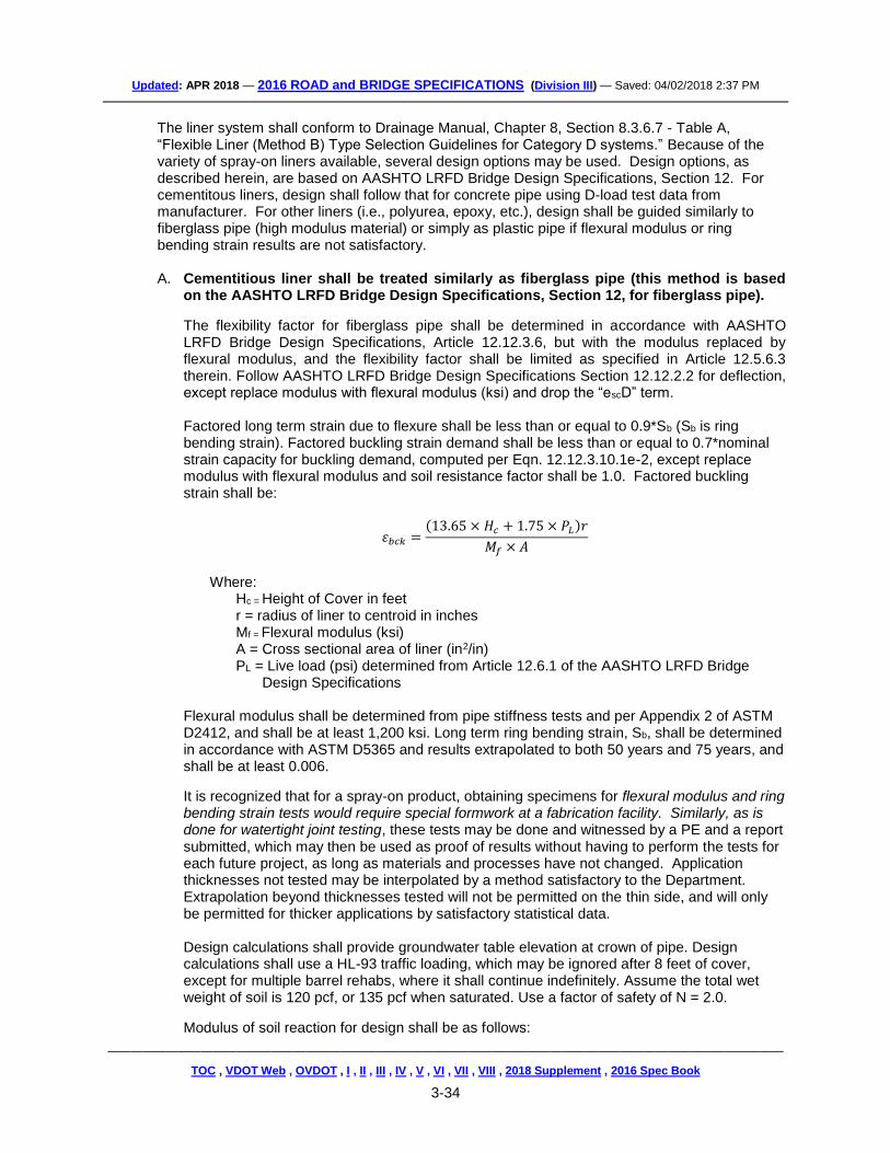
Factored long term strain due to flexure shall be less than or equal to 0.9*Sb (Sb is ring bending strain). Factored buckling strain demand shall be less than or equal to 0.7*nominal strain capacity for buckling demand, computed per Eqn. 12.12.3.10.1e-2, except replace modulus with flexural modulus and soil resistance factor shall be 1.0. Factored buckling strain shall be:
𝜀𝑏𝑐𝑘 =(13.65 × 𝐻𝑐 + 1.75 × 𝑃𝐿)𝑟
𝑀𝑓 × 𝐴
Where:
Hc = Height of Cover in feet r = radius of liner to centroid in inches Mf = Flexural modulus (ksi) A = Cross sectional area of liner (in2/in) PL = Live load (psi) determined from Article 12.6.1 of the AASHTO LRFD Bridge
Design Specifications Flexural modulus shall be determined from pipe stiffness tests and per Appendix 2 of ASTM D2412, and shall be at least 1,200 ksi. Long term ring bending strain, Sb, shall be determined in accordance with ASTM D5365 and results extrapolated to both 50 years and 75 years, and shall be at least 0.006.
It is recognized that for a spray-on product, obtaining specimens for flexural modulus and ring bending strain tests would require special formwork at a fabrication facility. Similarly, as is done for watertight joint testing, these tests may be done and witnessed by a PE and a report submitted, which may then be used as proof of results without having to perform the tests for each future project, as long as materials and processes have not changed. Application thicknesses not tested may be interpolated by a method satisfactory to the Department. Extrapolation beyond thicknesses tested will not be permitted on the thin side, and will only be permitted for thicker applications by satisfactory statistical data. Design calculations shall provide groundwater table elevation at crown of pipe. Design calculations shall use a HL-93 traffic loading, which may be ignored after 8 feet of cover, except for multiple barrel rehabs, where it shall continue indefinitely. Assume the total wet weight of soil is 120 pcf, or 135 pcf when saturated. Use a factor of safety of N = 2.0.
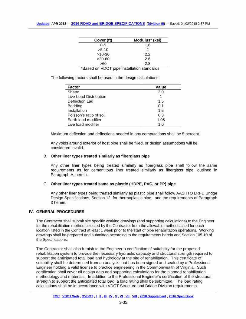
Modulus of soil reaction for design shall be as follows:
TOC , VDOT Web , OVDOT , I , II , III , IV , V , VI , VII , VIII , 2018 Supplement , 2016 Spec Book
3-35
Cover (ft) Modulus* (ksi)
0-5 1.8 >5-10 2 >10-30 2.2 >30-60 2.6
>60 2.8
*Based on VDOT pipe installation standards The following factors shall be used in the design calculations:
Factor Value
Shape 3.0 Live Load Distribution 1 Deflection Lag 1.5 Bedding 0.1 Installation 1.5 Poisson’s ratio of soil 0.3 Earth load modifier 1.05 Live load modifier 1.0
Maximum deflection and deflections needed in any computations shall be 5 percent. Any voids around exterior of host pipe shall be filled, or design assumptions will be considered invalid.
B. Other liner types treated similarly as fiberglass pipe
Any other liner types being treated similarly as fiberglass pipe shall follow the same requirements as for cementitous liner treated similarly as fiberglass pipe, outlined in Paragraph A, herein.
C. Other liner types treated same as plastic (HDPE, PVC, or PP) pipe
Any other liner types being treated similarly as plastic pipe shall follow AASHTO LRFD Bridge Design Specifications, Section 12, for thermoplastic pipe, and the requirements of Paragraph 3 herein.
IV. GENERAL PROCEDURES
The Contractor shall submit site specific working drawings (and supporting calculations) to the Engineer for the rehabilitation method selected by the Contractor from the allowable methods cited for each location listed in the Contract at least 1 week prior to the start of pipe rehabilitation operations. Working drawings shall be prepared and submitted according to the requirements herein and Section 105.10 of the Specifications. The Contractor shall also furnish to the Engineer a certification of suitability for the proposed rehabilitation system to provide the necessary hydraulic capacity and structural strength required to support the anticipated total load and hydrology at the site of rehabilitation. This certificate of suitability shall be determined from an analysis that has been signed and sealed by a Professional Engineer holding a valid license to practice engineering in the Commonwealth of Virginia. Such certification shall cover all design data and supporting calculations for the planned rehabilitation methodology and materials. In addition to the Professional Engineer’s certification of the structural strength to support the anticipated total load, a load rating shall be submitted. The load rating calculations shall be in accordance with VDOT Structure and Bridge Division requirements.
TOC , VDOT Web , OVDOT , I , II , III , IV , V , VI , VII , VIII , 2018 Supplement , 2016 Spec Book
3-36
All work and equipment shall be contained within the existing right-of-way. In the event the Contractor deems a temporary construction easement necessary due to the selected method or product chosen by the Contractor, the Contractor shall obtain such additional easement for the Contractor’s convenience at no additional cost to the Department. The Contractor shall maintain all lanes of traffic at all times in accordance with the Contract unless otherwise directed by the Engineer. This maintenance of traffic shall include temporary detours if required by the Contractor’s method of operations to facilitate construction where permitted by the locality and the Department. When temporary detours are required, the Contractor shall design and construct temporary detours in accordance with Section 105.14 and Section 512 of the Specifications, and Standard GS-10 of the Standard Drawings. The Contractor shall notify the Engineer at least 48 hours prior to the initiation of rehabilitation operations at each location. In the event the selected method of rehabilitation requires disturbing existing surfaces or disturbs existing surfaces, these surfaces shall be restored in kind to their original pre-construction conditions after rehabilitation operations have been completed. The cost thereof shall be included in the price bid for Pipe Rehabilitation for the specified location. The Contractor shall obtain all required OSHA confined space entry permits where these are required by the Contractor’s operations and the scope of work in the Contract. The Contractor shall schedule and arrange the work so as not to be delayed by the acquisition of the proper permits. The Department has performed an inspection of the existing pipes in each location listed in the Contract to determine the extent and nature of each pipe’s deterioration or damage so as to designate the allowable methods of rehabilitation for the pipe at that specific site. Using the information collected from this inspection, the Department has determined, through its engineering analysis, the best practical methods of rehabilitation for each respective site (location) taking into account site specific conditions such as installation working space for the various types of liners, hydraulic capacity before and after rehabilitation, height of cover, soil density, and loading conditions, among other criteria. The Contractor shall determine how he plans to perform the work from the allowable methods and categories for each specified location or site indicated in the Contract. Regardless of the final method selected, the Contractor shall provide the Engineer documentation of the Contractor’s proposed procedures, materials, equipment, incidentals, and resources the Contractor plans to use to ensure successful rehabilitation of the existing pipes to assist the Engineer in monitoring the Contractor’s operations. The Contractor will not be permitted to substitute a different method or category, if designated, than that or those specified for the location described in the Contract.
The Contractor shall clear the existing pipe of any debris, protrusions higher than 1/2 inch, and any other potential obstructions prior to the start of rehabilitation efforts. The Contractor shall then thoroughly clean and prepare the host pipe prior to the liner installation. Cleaning shall conform to the recommendations or instructions of the liner manufacturer, producer, or supplier of the methodology planned for use. In the absence of such recommendations, the Contractor shall submit his proposed method for cleaning and preparing the host pipe for the Engineer’s review and acceptance. A copy of the proposed cleaning methodology and materials shall be provided to the Engineer at least two working days prior to beginning the work at that location. Contractor Pre-Installation Inspection – The Contractor shall perform a pre-installation visual or video inspection at the designated location of each pipe shown in the Contract not later than 1 week after cleaning the host pipe at that location. This visual or video inspection shall be conducted in accordance with the requirements of this specification and VTM 123 to verify pre-rehabilitation conditions. The inspection shall be performed in the presence of the Engineer. Video inspections
TOC , VDOT Web , OVDOT , I , II , III , IV , V , VI , VII , VIII , 2018 Supplement , 2016 Spec Book
3-37
shall be clearly labeled on the recording media with the actual time, date, and location of the pipe inspected. A copy of the video inspection shall be furnished to the Engineer prior to the start of rehabilitative construction. The cost of pre-Installation Inspection will be considered incidental to the cost of the rehabilitation. In the event the Contractor’s inspection shows the method of rehabilitation the Contractor had selected from the allowable methods is no longer viable at that location (as verified by the Engineer), the Contractor shall select another allowable method, if specified, from those designated in the Contract. If no other method is designated, or if other methods of rehabilitation are also now deemed impracticable at that location, further work will be determined in accordance with Section 104.03 of the Specifications.
V. PROCEDURES FOR APPROVED METHODS
The following methods of pipe rehabilitation are approved by the Department; however, not all methods may be appropriate for each individual location shown in the Contract. The Contractor shall consult the Contract to determine the methods (and categories if designated) that are permitted per the designated location. Individual methods shall conform to the criteria specified. 1. PIPE LINER METHODS
A. Method A - Corrugated steel pipe liner shall be rehabilitation by insertion of a rigid corrugated
steel pipe liner through an existing host pipe (36" diameter or larger corrugated or concrete pipe). Where required, pipe shall be joined by the use of coupling bands of an internal expansion type that shall provide a leak-proof joint after grouting.
Expansion devices shall be installed above the mid-point of the pipe. After the Engineer approves installation and alignment of the liner within the host pipe, the Contractor shall fully grout the annular space between the existing pipe and the liner with cement grout meeting Section II-1 herein. Prior to grouting, the annular space shall be adequately sealed at each end. Plug holes required for injection of grout shall be satisfactorily plugged and sealed following the grouting operation.
B. Method B - Flexible pipe liner shall be rehabilitation by the insertion of a flexible pipe liner into a host pipe. Method B rehabilitation, as indicated in the Contract, shall be accomplished by the use of the following categories of liner: ● Category A – Cured-In-Place Pipe (CIPP)
● Category B – Fold and Form flexible liners
● Category C – High Density Polyethylene (HDPE), Polyvinyl chloride (PVC), or polypropylene PP slip liners
● Category D – Spray-On liners
Installation and curing requirements of pipe sections for the various flexible pipe liners shall be according to the manufacturer instructions for the specific product as applicable. Joints shall meet the requirements of Section 30 of the AASHTO Bridge Construction Specifications and leak resistance as defined in AASHTO PP 63-09.
The Contractor shall furnish all information for the liner system the Contractor proposes to use to include, as applicable, individual components of the system, tube type (whether reinforced or non-reinforced), manufacturer name, type of resin including catalyst and proprietary chemicals, and the volume of resin required to achieve proper impregnation and curing, and installation instructions. All components of the system, including lot number and expiration date, shall be as recommended by the manufacturer for the specific system proposed for use. The Contractor
TOC , VDOT Web , OVDOT , I , II , III , IV , V , VI , VII , VIII , 2018 Supplement , 2016 Spec Book
3-38
shall submit such documentation and instructions from the manufacturer to the Engineer at least 3 working days prior to the start of installation to verify compliance with the requirements of this paragraph. The various categories of flexible liners shall conform to the following: (1) Method B, Category A – Cured-In-Place Pipe (CIPP) liner method. The Cured-In-Place
Pipe liner system shall be designed, fabricated, and installed in such a manner as to result in a maintained, full contact, tight mechanical fit to the internal circumference of the host pipe for its entire length. The installation shall adhere to the cure times and temperatures stipulated in the manufacturer’s recommended installation and cure specifications. The finished product shall be free of de-lamination, bubbling, rippling, or other signs of installation failure.
Pulled-in-place liner installation must be accomplished without significant liner twisting or stretching during installation. At no time shall the pulling force for liner installation exceed that established by the liner manufacturer. All Cured-In-Place Pipe installations shall be performed in the dry. The Contractor shall consider the cost to accommodate this requirement as incidental to the cost of the installation.
Curing for styrene-based, epoxy-based,, and vinyl ester-based CIPP may be accomplished by water, steam, or ultraviolet light and shall be according to the liner manufacturer's instructions. The Contractor shall submit preconstruction installation and cure specifications (to include site specific cure time and temperature calculations) and design calculations (stamped by a licensed Professional Engineer) to the Engineer a minimum of 3 working days prior to the proposed start of the liner installation. The Contractor shall place an impermeable sheet or other impermeable device immediately upstream and downstream of the host pipe prior to liner insertion to capture any possible raw resin spillage during installation. During and after installation the Contractor shall promptly remove and properly dispose of any waste materials. Where the pulled-in-place method of installation is used, the Contractor shall install a semi-rigid plastic slip sheet over any interior portions of the host pipe that could tear the outer film and any significant voids in the host pipe. The Contractor shall ensure there is no loss of impermeability of the inner and outer plastic films or pre-liner during installation. The Contractor shall promptly repair any pinholes or tears in the plastic films or pre-liner before proceeding with the installation. Where such damaged areas cannot be repaired, the Contractor shall promptly replace the impermeable plastic films or pre-liner before proceeding with the installation.
The Contractor shall not perform work without oversight of the Engineer or Inspector for the duration of the installation. The Contractor shall monitor temperature via a minimum of three thermocouples on the outer surface of the liner (one each at the upstream and downstream ends and one approximately mid-length of the host pipe) and automatically log cure time-temperature data with a print-out from the data logger and provide such information to the Engineer. The Contractor shall obtain and comply with all discharge-related permits, including air, water, and wastewater treatment (i.e. Publicly Owned Treatment Works). For any discharge to a Publicly Owned Treatment Works (POTW), the Contractor shall obtain advanced written approval from the receiving facility for acceptance of effluent waste before repair
TOC , VDOT Web , OVDOT , I , II , III , IV , V , VI , VII , VIII , 2018 Supplement , 2016 Spec Book
3-39
work can start and shall provide such documentation of the POTW discharge approval to the Engineer prior to the start of the installation. The Contractor shall capture and properly dispose of all cure water or steam condensate and be responsible for the proper transportation and off-site disposal of process residuals. The Contractor shall provide disposal documentation from the receiving facility to the Engineer. The Contractor shall comply with all the requirements of the POTW receiving the discharge. The Contractor shall thoroughly rinse the cured lined pipe with clean water and capture and properly dispose of rinse water prior to re-introducing flow. For styrene-based CIPP and vinyl ester-based CIPP, the Contractor shall employ the services of a qualified independent environmental services laboratory or environmental consultant to collect the samples specified below. The Contractor shall submit a completed Form C-9A to the recipients specified on the form within 4 weeks after completion of rehabilitation.
Water samples shall be collected within 3 feet of the pipe ends both before rehabilitation, and within one week after the pipe liner has cured in accordance with applicable monitoring requirements listed in 40 CFR Part 136. If samples cannot be collected from within 3 feet of the pipe ends, the Contractor shall collect them from as close to the pipe ends as possible. If water is not available to sample, samples of rinse water shall be used for the analyses. For all CIPP liners, water samples shall be analyzed for total organic carbon using EPA 9060a, chemical oxygen demand using EPA 410.3, temperature, and pH. Temperature and pH shall be determined on site using applicable methods listed in 40 CFR Part 136. For styrene-based liners, water samples shall also be analyzed for styrene using USEPA SW 846 Method 8260. Styrene concentrations in water samples shall not exceed 2.5 mg/L. For vinyl ester-based liners, samples shall also be analyzed for diallyl phthalate, which shall not exceed 0.4 mg/L. The Contractor shall submit a completed Form C-9A to the recipients specified on the form within 4 weeks after completion of the rehabilitation. Form C-9A is available from the VDOT website.
It shall be the Contractor’s responsibility to report and take appropriate corrective actions to contain and remediate any release of contaminants from cured-in-place process materials, effluent or condensate into the environment in accordance with applicable local, state or federal regulations and the Contract. The cost for such remediation shall be at the Contractor’s expense.
(2) Method B, Category B - Fold and form flexible liners shall be installed in accordance
with the requirements of ASTM F1216, ASTM F2019, ASTM F1743, or ASTM D5813 (as applicable) or as recommended by the liner manufacturer.
(3) Method B, Category C - High Density Polyethylene (HDPE), Polyvinyl chloride (PVC), or polypropylene (PP) slip liners shall be installed in accordance with the requirements of AASHTO M326 or in accordance with ASTM F1698 as applicable, or as recommended by the liner manufacturer. Cement grout used for filling the annular space shall meet Section II-1 herein.
(4) Method B, Category D - Spray-On cementitious and polyurea liners shall be installed in accordance with the liner material manufacturer’s instructions, and the Contract.
The Contractor shall perform all installations in the dry. The Contractor shall thoroughly rinse the lined pipe with clean water and capture and properly dispose of rinse water prior to re-introducing flow. The Contractor shall install a temporary curtain at the outlet and
TOC , VDOT Web , OVDOT , I , II , III , IV , V , VI , VII , VIII , 2018 Supplement , 2016 Spec Book
3-40
inlet to prevent overspray during installation. The Contractor shall reinstate water flow no sooner than 24 hours following installation.
(a) For cementitious spray-on liners, the Contractor shall prevent the escape of any rinse water from the lined pipe or otherwise capture it until the Contractor can either: pump it to a container for proper transportation and off-site disposal; or continuously monitor the pH of the rinse water until the pH is less than 9, whereupon the Contractor may release it.
(b) For polyurea spray-on liners, the Contractor shall employ the services of a qualified independent environmental services laboratory or environmental consultant to collect the samples specified below.
Water samples shall be collected within 3 feet of the pipe ends both before rehabilitation, and within one week after the pipe liner has cured in accordance with applicable monitoring requirements listed in 40 CFR Part 136. If samples cannot be collected from with 3 feet of the pipe ends, they shall be collected from as close to the pipe ends as possible. If water is not available to sample, samples of rinse water shall be used for the analyses. Samples shall be analyzed for total methylene diphenyl diisocyanate (MDI), methylenedianiline (MDA), and total cyanide. Concentrations of MDI and MDA in water samples shall not exceed 1,000 mg/L and 39 mg/L respectively. Water characterization for chemical oxygen demand (COD) using EPA 410.3 and total nitrogen (TN) concentrations using EPA 351.2 shall also be conducted. The Contractor shall submit a completed Form C-9A to the recipients specified on the form within 4 weeks after completion of rehabilitation. Form C-9A is available from the VDOT website.
It shall be the Contractor’s responsibility to report and take appropriate corrective actions to remediate any water quality alteration resulting from the lining materials in accordance with applicable local, state or federal regulations. The cost for such remediation shall be at the Contractor’s expense.
C. Method C – Smooth wall steel pipe liner shall be rehabilitation by the insertion of a smooth
wall steel pipe into the existing host pipe. Where required, liner pipe shall be joined by butt welds in accordance with AWWA C-206. The Contractor shall fully grout the annular space between the existing host pipe and the steel liner with cement grout meeting Section II-1 herein. The annular space between the existing pipe and the smooth wall steel liner shall not exceed 3 inches at any given point, unless otherwise approved by the Engineer. Prior to grouting, the annular space shall be sealed at each end of the host pipe. Holes required to facilitate injecting grout shall be plugged and sealed following grouting operations. In order to ensure stability during placement, the wall thickness of the liner shall not be less than 1/2 inch.
2. POST INSTALLATION INSPECTION OF FLEXIBLE LINERS – The Contractor shall perform a
post-installation inspection on all flexible liners installations in accordance with Section 302.03(d) of the Specifications and Virginia Test Method (VTM) 123. To be acceptable, the finished liner shall be continuously intact, fit snug tight against the host pipe over its entire length, and be free from visual defects such as foreign inclusions, dry spots, pinholes, and delamination.
In the event a post inspection of the installation reveals a tight fit of the liner was not achieved in localized areas of the host pipe (comprising less than 20 percent of the pipe length), the annular space between the liner and the host pipe shall be filled with a resin mixture or a non-shrink
TOC , VDOT Web , OVDOT , I , II , III , IV , V , VI , VII , VIII , 2018 Supplement , 2016 Spec Book
3-41
cementitious grout as specified by the manufacturer that is compatible with the liner system at no cost to the Department. Where a tight mechanical fit was not achieved on more than 20 percent of the host pipe’s length, the annular space shall be filled as designated herein; however, the Contractor will not be allowed to continue with his methodology of installation or the liner system used until the Contractor can demonstrate to the Engineer that the Contractor’s choice of liner system, installation methods or operations have been remedied to the extent that they can consistently result in a continuous snug tight mechanical fit between the installed liner and the host pipe for the full length of the host pipe. All such remedial efforts shall be at the Contractor’s expense. Further failure to perform a proper installation may result in the disallowance of the use of that liner system and an adjustment in the cost or non-payment of the failed installations depending on the severity of the failure. Adjustment or nonpayment of the installation will be at the sole discretion of the Engineer. In the event the post installation inspection is not conducted until all or most of the locations in the Contract permitting this methodology have been performed, and the inspection reveals a tight fit between host pipe and liner has not been achieved on 25 percent or more of the host pipe’s length or the finished liner is not free from visual defects such as foreign inclusions, dry spots, pinholes, and delamination, then an adjustment in the cost or non-payment of the failed installations maybe made by the Engineer depending on the severity of the failure. The cost of the post installation inspection will be considered incidental to the cost of the liner installation.
VI. MEASUREMENT AND PAYMENT Pipe rehabilitation will be measured and paid for in linear feet of pipe for the size, method, and category (if specified) as detailed in the Contract. At locations shown in the Contract where multiple methods are permitted, the Contractor may select from any of the methods specified (subject to the limitations described herein) however, if only one method is specified, this will be the only method permitted by the Department at that location. This price shall include pre installation visual or video inspection; cleaning and preparation of the host pipe; furnishing and installing the liner including coupling and expansion devices; cement grout; design and shop drawing preparation; furnishing and installing liner and all components of the liner system; capturing any discharges or releases during installation or curing operations; obtaining any local POWT, local, state, or federal permits required to perform the work; furnishing any documentation or fees required for effluent or condensate disposal; all testing and sampling including furnishing reports and post installation visual or video inspections for flexible liners; and waste disposal costs. Prices for pipe rehabilitation shall also include clearing debris and obstructions; excavating when not designated as a separate pay item attributable to this specific work; sheeting; shoring; dewatering; disposing of surplus and unsuitable material; providing backfill material and backfilling; compaction, and restoring existing surfaces. Payment will be made under:
Pay Item Pay Unit
Pipe Rehabilitation (Size, Method, Category) Linear Foot
TOC , VDOT Web , OVDOT , I , II , III , IV , V , VI , VII , VIII , 2018 Supplement , 2016 Spec Book
3-42
GUIDELINES - For use on all projects that use Prefabricated Vertical Drains (wick-drains).
SP302-000300-01
VIRGINIA DEPARTMENT OF TRANSPORTATION
SPECIAL PROVISION FOR PREFABRICATED VERTICAL DRAINS
January 8, 2018
I. DESCRIPTION
The work shall consist of furnishing and installing prefabricated vertical drains (PVDs) in accordance with the Plans, Specifications and this Special Provision. The drains shall consist of a nominally 4-inch wide, band-shaped plastic core enclosed in a geotextile fabric-wrapped jacket and shall be spaced and arranged as shown on the plans or as directed by the Engineer.
II. DEFINITIONS
All terms and definitions outlined in ASTM D4439 shall apply in this specification.
III. MATERIALS
1. PVD
PVDs shall be currently listed on Materials Division Approved List No. 39.
The PVD shall be newly manufactured materials and consist of a polyethylene or polypropylene drainage core enclosed in or integrated with a geotextile jacket. The geotextile jacket shall be made of non-woven fabric and continuous filaments of 100 percent polypropylene or polyethylene. The strip drain or its components shall have the physical characteristics outlined below.
A. The geotextile jacket shall allow free passage of pore water to the core without loss of soil material or piping.
B. The core shall provide continuous vertical drainage paths.
C. The PVD shall be capable of resisting all bending, punching, compression, and tensile forces imposed during install and during the design life of the drain without damage and so that the discharge capacity is not adversely affected.
D. Anchors shall be free of rust and sharp or jagged edges.
E. Anchor plates, if used, shall not exceed 8 inches in the maximum horizontal dimension.
F. The geotextile jacket material shall conform to the following minimum specifications, which shall be shown by testing provided for every 1.5 million linear feet of product, the test results being traceable to the product on which they were run and samples of the tested product retained for one year from test date, and tested either by GAI-LAP certified laboratories certified in the individual tests, or by laboratories verified via split sampling at least once every three years with such GAI-LAP certified labs.
G. The core shall be continuous polyethylene or polypropylene plastic material fabricated to
promote drainage along the axis of the PVD, and shall conform to the following minimum specifications:
Test Item Requirement Designation Minimum Average Roll Value
Grab tensile strength on full drain width
ASTM D4595 225 lbs
H. The mechanical properties (strength and modulus) of the assembled PVD shall equal or
exceed those specified for the component geotextile jacket and core.
I. The assembled drain shall be resistant against wet rot, mildew, bacterial action, insects, salts in solution in the groundwater, acids, alkalis, solvents, and any other significant ingredients in the site groundwater for three years.
J. One single type of assembled PVD shall be used on the project unless otherwise specified or approved by the Engineer. The assembled drain shall have the following minimum properties:
Test Item Requirement Designation Minimum Average Roll Value
A. PVD materials shall be labeled or tagged in such a manner that the information for sample identification and other quality control purposes can be read from the label. As a minimum, each roll shall be identified by the manufacturer as to lot or control numbers, individual roll number, date of manufacture manufacturer, and project identification on the jacket and core.
B. During shipment and storage, the PVD shall be wrapped in heavy paper burlap, plastic, or a similar heavy-duty protective covering. The PVD shall be protected from sunlight, dirt, debris, and other detrimental substances during shipping and on-site storage.
C. All material which is damaged during shipping, unloading, storage, or handling; or which does not meet the minimum requirements of the PVD material will be rejected by the
TOC , VDOT Web , OVDOT , I , II , III , IV , V , VI , VII , VIII , 2018 Supplement , 2016 Spec Book
3-44
Engineer. No payment will be made for rejected material.
IV. QUALIFICATIONS
1. CONTRACTOR QUALIFICATIONS
The Contractor shall have a minimum of five years of experience with the installation of PVDs and shall have completed three or more PVD installations of similar size and complexity within the last five years. Provide at least one superintendent and one operator for the PVD equipment each with a minimum of five years of experience with the equipment and with PVD installation. Alternatively, the Contractor shall provide detailed information on the training and experience of any superintendents or operators with less than five years but at least two years of experience for approval by the Engineer.
2. SUBMITTALS
The Contractor shall submit proposed actions and schedule to address any deficiencies within five business days after receiving a list of deficiencies. The Contractor shall allow 15 calendar days for the Engineer to evaluate and approve all submissions. The Contractor shall submit required data and state which PVD product they intend to install at least 21 calendar days prior to the start of PVD installation. Approval by the Engineer will not relieve the Contractor of its responsibilities to provide material and equipment necessary to install the PVDs in accordance with the plans and specifications. If the method of installation does not produce a satisfactory drain, the Contractor shall alter its method or equipment as necessary to comply with the Plans and Specifications.
A. Qualifying Experience
The Contractor shall submit proof of three or more projects of similar size and complexity on which they have installed PVDs within the last five years. Identify the projects by project name, location, project description, length of the PVDs installed, linear footage of the PVDs installed, completion date, geotechnical consultant, owner/designer, and contract manager. Provide phone numbers and business addresses for the owner/designer, geotechnical consultant, and contract manager. Present the following information for each project listed as a reference:
(1) Project name, location and completion date
(2) Surface and subsurface conditions
(3) PVD installation equipment and technique
(4) Minimum, maximum, and average rates of PVD installation
(5) Cost and duration of PVD installation
(6) Average length of PVD installed and total linear footage of PVD installed
(7) Current phone numbers and business addresses for the owner/designer, geotechnical consultant, and contract manager
TOC , VDOT Web , OVDOT , I , II , III , IV , V , VI , VII , VIII , 2018 Supplement , 2016 Spec Book
3-45
The Contractor shall provide written notice of intended schedule to Engineer at least 21 days prior to the installation of any PVDs.
C. Installation Procedures
The Contractor shall submit to the Engineer details of the sequence and method of installation. The submittal shall, at a minimum, contain the following specific information concerning the scheduled work.
(1) Size, type, weight, maximum pushing force, actual pushing force for anticipated set-up, track bearing pressure, and the configuration of the installation rig.
(2) Shop drawings showing PVD layout and identification numbers.
(3) Dimensions, weight, materials, and length of the mandrel.
(4) Details of PVD anchorages that are anticipated.
(5) Means of determining the depth of the advancing drain at any given time and the length of the drain installed at each location.
(6) Detailed description of proposed installation procedures.
(7) Estimated minimum, maximum, and average rates of PVD installation.
(8) Proposed methods for penetrating existing embankment fill or subsurface obstructions.
(9) Proposed plan for constructing a level working surface for installation of PVDs.
(10) Manufacturer’s literature on PVD installation.
D. Certification of PVD Properties and Handling
Provide manufacturer’s Certification that delivered materials, identified by lot number, meet specification requirements, prior to delivery of PVDs. Provide supplier’s Certification that delivered material, identified by lot number, has been properly stored away from sunlight, moisture, and dirt.
E. Samples of PVDs
Submit 3 samples of the PVD and 3 samples of any proposed splices. Each sample shall be at least 5 feet long. Samples of spliced PVD shall be long enough to include the splice plus 2 feet of unspliced drain on both sides of the splice.
F. Installation Records
Submit proposed installation record forms including date and time of inspection, PVD identification number, installed length, length of pre-augering or spudding, description of obstruction or other interruptions, daily quantity summary, total quantity summary, and other contract summary items. Interim reports shall be submitted weekly. A complete copy shall be submitted within two weeks after completion of PVD installation.
TOC , VDOT Web , OVDOT , I , II , III , IV , V , VI , VII , VIII , 2018 Supplement , 2016 Spec Book
3-46
A. Prior to bidding, the Contractor shall visit and examine the work site and all conditions thereon and take into consideration all such conditions that may affect this work, in accordance with Section 102.04 of the Standard Specifications. Any subsurface data obtained by VDOT available for review may be obtained by contacting the District Materials Office.
B. Protection of Existing Structures: Protect structures, underground utilities, and other construction from damage by PVD installation.
V. EXECUTION
1. EQUIPMENT
A. Equipment shall be of a type that will cause a minimum of disturbance of the subsoil during the installation operation and shall maintain the mandrel in a vertical position.
B. PVDs shall be installed using a mandrel or sleeve that shall be inserted (pushed) into the soil. The mandrel or sleeve shall protect the drain material from tears, cuts, and abrasions during installation, and shall be retracted after each drain is installed.
C. The mandrel or sleeve shall be straight and shall be sufficiently stiff to prevent wobble or deflection during installation.
D. To minimize disturbance of the subsoil, the mandrel, sleeve, and shoe shall have a maximum cross-section area of 12.1 sq. in.
E. When requested by the Contractor and approved by the Engineer, a maximum 8-inch diameter auger/drill/spud/etc. shall be used to pre-drill or spud through obstructions and/or hard and dense materials.
F. The mandrel or sleeve shall be provided with an anchor rod, plate, or similar arrangement at the bottom to permit the installation of the drain and to anchor the drain tip at the required depth at the time of mandrel withdrawal. The dimensions of the anchor shall conform as closely as possible to the dimensions of the mandrel so as to minimize soil disturbance. The Engineer will determine the acceptability of the anchorage system and installation procedure.
G. The choice of anchoring system is the responsibility of the Contractor, but it shall be the smallest surface area required to secure the PVD.
2. TRIAL INSTALLATIONS
A. Prior to installation of the PVDs within the required areas, the Contractor shall demonstrate that its equipment, method, and materials produce a satisfactory installation. The Contractor shall provide the trial PVDs at locations designated by the Engineer. Approximately 4 trial PVDs shall be installed. The Engineer may also choose trial areas to determine the need for pre-augering prior to production installation. Additional trial PVDs shall be installed, as required by the Engineer, or as approved by the Engineer when significant changes in the subsurface conditions or installation are encountered by the Contractor.
B. All trial drains provided to the satisfaction of the Engineer will be measured and paid for as Prefabricated Vertical Drains.
TOC , VDOT Web , OVDOT , I , II , III , IV , V , VI , VII , VIII , 2018 Supplement , 2016 Spec Book
3-47
A. If, at any time, the approved method does not produce satisfactory PVDs, the Contractor shall alter his method or equipment as necessary to comply with these Specifications at no additional expense to the Department.
B. The Contractor shall provide a level (less than 2% grade change) work area of at least 25 feet wide.
C. PVDs shall be located, numbered, and staked by the Contractor, relative to a baseline and benchmark provided by the Engineer. The Contractor shall take all reasonable precautions to preserve the stakes and is responsible for any re-staking. The as-installed location of the PVDs shall not vary by more than 12 inches from the plan locations designated on the drawings.
D. PVDs shall be installed from the working surface to the elevation shown on the drawings, or to such elevation as directed by the Engineer. The Engineer may vary the depths, spacing, or the number of drains to be installed, and may revise the plan limits for this work as necessary.
E. During PVD installation, the Contractor shall provide the Engineer with suitable means of determining the depth of the advancing PVD at any given time and length of the drain installed at each location.
F. PVDs shall be installed using either constant load or constant rate of advancement methods, together known as “static methods.” A vibrator shall be available for use only in areas where the constant load or constant rate of advancement methods cannot install the PVDs by using the full static force available to the mandrel to the design elevations. PVD which cannot be installed to the design penetration using only static methods shall be advanced with the use of the vibrator, and will be considered for compensation. The vibrator shall only be used in cases where design penetration cannot be achieved.
G. PVDs that are more than 12 inches from the design plan location or are damaged or improperly installed will be rejected and abandoned in place and will not be measured for payment. The Contractor shall install additional wick drains to replace unacceptable PVDs.
H. Where PVDs are to be installed through the existing embankments or through hard and dense materials, the Contractor shall pre-drill or spud through the obstructions prior to installation of the PVD, as required by site conditions and with approval of the Engineer.
I. A PVD shall be abandoned before reaching the design penetration when the rate of installation is less than 6 inches per second with the full static force and maximum vibrator output. The use of falling weight impact hammers is not allowed.
J. Equipment for testing PVDs shall be plumbed prior to installing each drain and shall not deviate from the vertical more than 5 inches in 10 feet during installation of any drain.
K. Installation techniques requiring driving or jetting will not be permitted. The injection of limited amounts of water shall be allowed to facilitate anchoring of the PVDs.
L. The installation shall be performed without any damage to the drain during advance or retraction of the mandrel. In no case will alternate raising or lowering of the mandrel during advance be permitted. Raising the mandrel will only be permitted after completing the drain installation.
M. There shall be a 12-inch section of the PVD material protruding above the ground surface at
TOC , VDOT Web , OVDOT , I , II , III , IV , V , VI , VII , VIII , 2018 Supplement , 2016 Spec Book
3-48
each PVD location. The PVD material shall be cut neatly at its upper end at the working grade, or as specified in the contract drawings.
N. Where obstructions are found below the working surface, which cannot be penetrated using normal and accepted procedures, the Contractor shall complete the drain from the elevation of the obstruction of the working surface and notify the Engineer.
O. The Contractor shall observe precautions necessary for protection of any existing utilities, structures, and field instrumentation devices. The Contractor shall pay for replacement of any instrumentation equipment that has been damaged or becomes unreliable as a result of his operations.
4. PRE-AUGERING/OBSTRUCTIONS
A. The Contractor shall be responsible for penetrating overlying fill material as necessary to satisfactorily install the PVDs. Satisfactory installation may require clearing obstructions defined as any man-made or natural object or strata that prevents the proper insertion of the mandrel and installation of the PVD.
B. The Contractor may use augering, spudding, or other approved methods to loosen the soil and any obstruction material prior to the installation of the PVDs. The obstruction clearance procedure is subject to approval of the Engineer.
C. When obstructions are found, the Contractor shall immediately notify the Engineer prior to completing the drain and prior to installing any other drains. The Contractor shall attempt to install drains adjacent to the obstructed location, in the presence of the Engineer. Based upon the results of these installations and at the direction of the Engineer, the Contractor shall:
(1) Attempt to install an offset drain within 18 inches horizontally of the obstructed drain; or
(2) Implement obstruction clearance procedures and install the drain at the design location. Obstruction clearance procedures shall be used only as directed by the Engineer.
5. SPLICING
A. Splicing of PVD material shall be done by stapling to insure structural and hydraulic continuity of the drain.
B. The jacket and core shall be overlapped by a minimum of 6 inches at any splice.
C. A maximum of one splice per drain installed will be permitted without specific permission from the Engineer.
VI. MEASUREMENT AND PAYMENT
Prefabricated Vertical Drains (PVD) will be measured in linear feet and will be paid for at the Contract linear foot price, measured to the nearest linear foot from the ground surface to the installed depth of the anchor, complete in place. This price shall include grading the work area, furnishing, installing and splicing PVDs and all labor, materials, tools and equipment necessary to complete the work.
Trial drains installed as directed by the Engineer will be measured and paid for as Prefabricated Vertical Drains, even if they do not function as intended.
TOC , VDOT Web , OVDOT , I , II , III , IV , V , VI , VII , VIII , 2018 Supplement , 2016 Spec Book
3-49
Obstructed PVDs will be paid for at the contract unit price for PVDs, as measured to the nearest foot from the bottom of the vertical strip drains (at the obstruction), to ground surface.
The length of the PVD extending above the ground surface will not be measured for payment.
Pre-Augering will be measured in linear feet and will be paid for at the Contract linear foot, measured from the bottom of the obstruction depth to the ground surface to the nearest foot. This price shall include pre-drilling (augering, spudding, rotary air flush drilling, open hole with roller bits, hydraulic excavator with hydraulic hammer and pick, etc.) and removing or driving through (spudding) subsurface obstruction (dense natural soils or man-made fill materials, buried debris, etc.) to maximum depth of 15 feet below ground surface and all labor, materials, tools and equipment necessary to complete the work.
PAY ITEM PAY UNIT
Prefabricated Vertical Drains (PVD) Linear feet Pre-Augering Linear feet
TOC , VDOT Web , OVDOT , I , II , III , IV , V , VI , VII , VIII , 2018 Supplement , 2016 Spec Book
3-50
GUIDELINES: Use this spec where the Contractor has recommended Number 10 Screenings for use on certain items as a Value Engineering Proposal, or where Number 10 Screenings are specified as an alternate bid item. If the Plans specifically require Number 10 Screenings, contact the State Specifications Engineer for clarification before use.
SP303-020100-00
VIRGINIA DEPARTMENT OF TRANSPORTATION SPECIAL PROVISION FOR
USE OF NUMBER 10 SCREENINGS
April 28, 2017 I. DESCRIPTION
This Special Provision cover the use of No. 10 Screenings in various applications on the Project. No. 10 Screenings shall be used in locations designated in the Contract.
II. MATERIALS
1. No. 10 Screenings (also known as quarry dust, rock dust, quarry screenings, rock screenings and quarry byproduct) may be used as an acceptable source of borrow material for the applications described herein. No. 10 Screenings shall conform to the requirements herein and elsewhere in the Contract. For the purpose of this Special Provision, No. 10 Screenings shall be defined as any material that is a byproduct of rock crushing processes, and either has a gradation of 100% passing the 3/8” Sieve and less than 20% passing the No. 200 Sieve, or meets the No. 10 coarse aggregate gradation. No. 10 Screenings shall also have a minimum CBR value of 15 and be either non-plastic or have liquid limit less than 25 and a plasticity index less than 9.
2. Low-plasticity clay or silt shall conform to classification CL or ML according to ASTM D2487.
III. PROCEDURES
1. Embankment
No. 10 Screenings shall be compacted to 95% of Standard Proctor dry density, and shall be compacted in the field within a water content range of 2 percentage points either side of the optimum water content. For laboratory optimum water contents greater than 9%, a field optimum water content target of 8.5% shall be used. Both dry density and optimum water content shall be obtained according to VTM-1. When landscaping is required in areas of No. 10 Screenings use, the Contractor shall make accommodations for landscaping as trees and larger shrubs will not be able to root properly in No. 10 Screenings. The top and sides of unconfined areas consisting solely of No. 10 Screenings shall be capped with low-plasticity clay or silt material to deter water from penetrating into and saturating embankments constructed of No. 10 Screenings. Fills less than 10 feet in height shall be capped on the sides and top with a minimum 2 feet of low-plasticity clay or silt. At a minimum, fills greater than 10 feet in height shall be capped with 3 feet of low-plasticity clay or silt. In low-lying areas, drainage areas or areas identified as active or potential wet zones during construction, a separation layer between the bottom of the placed fill and original ground shall be placed to mitigate the potential destabilization of a No. 10 Screenings embankment. The separation layer should be at least 8-inches thick and composed of No. 1 or No. 57 aggregate or another open graded aggregate wrapped in drainage fabric. Riprap bedding fabric meeting the requirements of Section 245 of the Specifications shall be placed between the separation layer and the No. 10 Screenings.
TOC , VDOT Web , OVDOT , I , II , III , IV , V , VI , VII , VIII , 2018 Supplement , 2016 Spec Book
3-51
If an embankment greater than 10 feet in height is constructed, survey points shall be taken after the fill is complete at bi-weekly intervals until 2 consecutive measurements are each less than ¼ inch to ensure that settlement is not occurring. If settlement issues are identified, the Contractor or Design-Builder shall mitigate the causes of settlement as needed (e.g., additional asphalt, ground improvement techniques, removing and replacing settled locations if isolated, etc.).
2. Structure backfill, building foundation soil, road subgrade, undercut replacement, fill under approach slabs
No. 10 Screenings used for these purposes shall have a CBR of at least 30, shall be compacted to 95% of Standard Proctor dry density (100% under approach fills), and shall be compacted in the field within a water content range of 2 percentage points either side of the optimum water content. For laboratory optimum water contents greater than 9%, a field optimum water content target of 8.5% should be used. Both dry density and optimum water content shall be obtained using VTM-1. These applications should typically be in confined areas. Where there is no confinement, capping of the unconfined sides shall be as in Paragraph 1 above. In low-lying areas, drainage areas or areas identified as active or potential wet zones during construction, the No. 10 Screenings shall be wrapped in drainage fabric.
3. Pipe Backfill
Pipe backfill shall be performed in accordance with Standard Drawing PB-1 and Section 302.03(a)2g of the Specifications unless noted herein. No. 10 Screening may be used as either Regular Backfill or Class I Backfill, as shown in Standard Drawing PB-1. Regular Backfill material within the limits of roadway embankments and under existing or proposed roadway shall meet a minimum CBR value of 15.0 as determined by VTM-8. Ground line shall be considered the top of trench at the time of pipe installation. When pipe does not project above ground line, Regular Backfill shall extend to the top of the pipe trench in fills or subgrade in cuts. Outlet pipes for storm water management basins shall be installed as noted on the plans. The cost of furnishing, placing and compacting the Regular Backfill and disposing of unsuitable material excavated from the trench shall be included in the price of the pipe and will not be measured and for separate payment.
4. Reinforced Fill for Mechanically Stabilized Earth Walls
No. 10 Screenings used for these purposes shall have a friction angle of at least 34 degrees, with up to 60% passing the No. 40 sieve. They shall be compacted to 95% of Standard Proctor dry density, and shall be compacted in the field within a water content range of 2 percentage points either side of the optimum water content. For laboratory optimum water contents greater than 9%, a field optimum water content target of 8.5% should be used. Both dry density and optimum water content shall be obtained using VTM-1. If the use of No. 10 Screenings conflicts with any other Contract requirement for reinforced fill for MSE walls, No. 10 Screenings shall not be used for this purpose.
5. Soft ground stabilization
No. 10 Screenings may be used as a replacement or stabilizing agent for soft or unsuitable soils in parking areas, under building pads or foundations, or under roadways. In the event soft or unsuitable soils are identified, No. 10 Screenings may replace or be mixed into the soil in a prescribed percentage to improve the bearing capacity of the soil. Replacement shall require confinement by surrounding ground. For mxing, the percentage of screenings to be used shall be determined by sampling the soft/unsuitable soil and mixing with varying percentages of No. 10 Screenings in the laboratory. Proctor samples and CBR samples of each mixture shall be prepared in accordanceVTM-1 and VTM-8, respectively. The mixture resulting in the desired minimum CBR will determine the minimum amount of No. 10 Screenings to be used. Field mixing of the No. 10 Screenings shall be accomplished by layering the appropriate amount of screenings on top of the soft/unsuitable soil followed by blending to a depth of 8 inches to achieve the blend percentage determined in the laboratory. Mixing shall be accomplished by means of a self-
TOC , VDOT Web , OVDOT , I , II , III , IV , V , VI , VII , VIII , 2018 Supplement , 2016 Spec Book
3-52
propelled or self-powered machine equipped with a mechanical rotor or other approved type of mixer that will thoroughly blend the No 10 Screenings with the soil.
IV. MEASUREMENT AND PAYMENT
No. 10 screenings, when a pay item, will be measured in tons, and paid for at the Contract ton price based on certified weigh tickets from the source of supply. This price shall include furnishing, transporting, and placing No. 10 screenings; and all work incidental to their use (e.g., capping embankments in accordance with Section III-1 herein). Payment will be made under:
TOC , VDOT Web , OVDOT , I , II , III , IV , V , VI , VII , VIII , 2018 Supplement , 2016 Spec Book
3-53
GUIDELINES — For projects where the existing shoulder is out of compliance with the road and bridge standards either due to plant mix overlay work or because the existing shoulder was already out of compliance. This includes shoulder work in areas scheduled for new guardrail, guardrail improvements or guardrail replacements. {2007-S305EM3}
SP305-000100-01
VIRGINIA DEPARTMENT OF TRANSPORTATION SPECIAL PROVISION FOR SHOULDER RENOVATION
October 3, 2016
I. DESCRIPTION
This work shall consist of renovating existing low (erosion or overlay) and high shoulders (debris buildup) and shoulders disturbed due to plant mix overlay or guardrail work as specified in the Contract Documents to provide finished shoulder designs and guardrail heights that conform to the Specifications, Standard Drawings, and Plans. For the purposes of this provision, machining shoulders and manual shoulder restoration shall be viewed as placing, grading, and compacting operations of approved shoulder materials performed by mechanized equipment or manually. Materials allowed for renovating shoulders shall include furnishing and delivery of these materials to the jobsite or to the location(s) designated in the Contract Documents.
II. MATERIALS Shoulder material shall be either virgin aggregate base material (type and size as specified) or Shoulder Maintenance Material (SMM). SMM shall be: Aggregate Material; Crusher Run Aggregate; Aggregate Subbase or Base; Select Material; recycled materials including Reclaimed Asphalt Pavement (RAP) or Crushed Hydraulic Cement Concrete (CHCC); or combinations thereof, conforming to the followings grading when tested in accordance with VTM-25:
% by Weight of Material Passing Sieve
1-1/2 in 1 in No. 4
100 80-100 20-60
Shoulder Maintenance Material, if used, shall be 1-1/2 inch maximum size as determined visually, using VTM-25, or by field measurement. Shoulder Maintenance Material shall have a loose, unconsolidated consistency and shall not contain any clusters of materials that exceed the 1-1/2-inch grading requirement. Material out of conformance with the maximum size limitation will be rejected. However, a sample of material shall be tested for gradation using VTM-25; test results within the last year may be used for stockpile material. Shoulder Maintenance Material, when comprised of blended aggregate, RAP, or CHCC, shall be thoroughly mixed (manipulated) and shall have a dappled appearance when placed, graded, and compacted. The use of Shoulder Maintenance Material is subject to the limitations as described herein and elsewhere in the Special Provision Copied Note for Alternate Category Bid Items and Award of Contract included in the Contract.
TOC , VDOT Web , OVDOT , I , II , III , IV , V , VI , VII , VIII , 2018 Supplement , 2016 Spec Book
3-54
III. PROCEDURES
The use of more than one type of approved material on uninterrupted runs of shoulder work will not be permitted. The use of CHCC or any CHCC blended material as SMM will only be permitted in areas 3 feet in width or less and no more than 3 inches in compacted depth once placed. Shoulder material shall be spread, graded, and compacted according to Section 305.03(e) of the Specifications, except as noted herein. Subgrade shaping will generally not be required unless directed by the Engineer. However, when shaping of the subgrade is required, the cost of such work shall be included in the cost of machining shoulders or manual shoulder renovation work. The maximum compacted lift thickness of shoulder material (except CHCC or CHCC blends) shall be 6 inches. The acceptability of furnished and finished (compacted) shoulder material will be determined by visual inspection, field measurement, or a combination thereof, at the discretion of the Engineer. Final pavement surface edge or final paved or stabilized shoulder surface edge shall include existing pavement not designated for overlay and completely compacted pavement overlays, and their corresponding shoulders. The Contractor shall promptly remove and dispose of surplus shoulder material encountered as a result of shoulder renovation work as well as any shoulder material spilled, left or tracked on the pavement.
Grading for shoulder renovation shall be performed by the following methods: A. Machining shoulders shall be performed in areas where there is no existing guardrail
and none is scheduled to be placed or updated under this contract, in areas with existing guardrail where that guardrail will not be disturbed, in areas scheduled for new guardrail installation before new guardrail is installed, or in areas where existing guardrail will be removed in preparation for guardrail improvement or guardrail replacement. In each of these grading situations it is to be assumed grading can be performed by mechanized equipment unencumbered by existing or newly installed guardrail. Machining shoulders shall include grading shoulders to appropriate slope and grade where sufficient material is present to renovate the existing shoulders, grading existing shoulders to fill in low areas after shoulder material has been placed, or grading down areas where high shoulders exist due to debris buildup. Machining shoulders shall result in a uniformly finished slope to the shoulder break that conforms to the Standard Drawings and the included sketch after compaction. Renovated shoulders shall smoothly tie the graded shoulder edge elevation to the adjoining elevation of the final pavement surface edge and final paved or stabilized shoulder surface edge.
B. Manual shoulder restoration shall be used to renovate shoulders in areas where
existing guardrail will be undisturbed by adjacent plant mix or other operations specified in the contract.
Manual shoulder restoration shall include grading shoulders around existing guardrail by hand or other intensive production methods to appropriate slope and grade where
TOC , VDOT Web , OVDOT , I , II , III , IV , V , VI , VII , VIII , 2018 Supplement , 2016 Spec Book
3-55
sufficient material is present to restore the existing shoulders, grading existing shoulders to fill in low areas after shoulder material has been placed, or grading down areas where high shoulders exists due to debris buildup. Manual shoulder restoration shall result in a uniformly finished slope to the shoulder break that conforms to the Standard Drawings and the included sketch after compaction. Restored shoulder work shall smoothly tie the graded shoulder edge elevation to the adjoining elevation of the final pavement surface edge and final paved or stabilized shoulder surface edge. Note: Shoulder material specified in this Special Provision is the only allowable material for manual shoulder restoration work unless otherwise approved by the Engineer.
Shoulder material (depending on the type of shoulder renovation operation specified in the Contract Documents or directed by the Engineer) shall be furnished and placed by the Contractor in low shoulder areas, then machined or manually graded off as necessary, and then compacted to provide a finished cross slope that conforms to the applicable Standard Drawings as well as the existing road profile grade.
Where guardrail is to be installed or reinstalled, the placement widths and limits of shoulder material shall be according to the detail requirements for the specific type of guardrail as designated in the Contract Documents and as shown in the Standard Drawings, the attached sketch, or as otherwise indicated in the Contract Documents. Guardrail height shall conform to the Standard Drawings for the applicable guardrail type once work is completed. This work shall proceed as directed by the Engineer.
IV. MEASUREMENT AND PAYMENT
Machining shoulders will be measured in linear feet along the adjacent edge of pavement and will be paid for at the Contract unit price per linear foot. The price shall include placing, grading, and compaction. This price shall also include removing and disposing of surplus, spilled, and tracked material resulting from the Contractor’s operations. Manual shoulder restoration will be measured in linear feet along the adjacent edge of pavement specified in the Contract or directed by the Engineer, and will be paid for at the Contract unit price per linear foot. The price shall include placing, grading, and compaction. This price shall also include removing and disposing of surplus, spilled, and tracked material resulting from the Contractor’s operations. Virgin aggregate base material will be measured in tons and will be paid for at the Contract unit price per ton. The price bid shall include furnishing and delivery. Shoulder Maintenance Material, if requested and authorized for use, will be measured in tons or square yards and will be paid for at the Contract unit price per ton as bid in Section 0002 of the Special Provision Copied Note for Alternate Category Bid Items and Award of Contract. The price bid shall include furnishing and delivery. Tonnage for Shoulder Maintenance Material will be based on certified weigh tickets from the source of supply, or when supplied directly from the field, will be computed on the basis of 110 pounds per inch of depth per square yard, converted to tons.
TOC , VDOT Web , OVDOT , I , II , III , IV , V , VI , VII , VIII , 2018 Supplement , 2016 Spec Book
3-56
Payment will be made under:
Pay Item Pay Unit
Virgin Aggregate Base Material, Type ( ), No. ( ) Ton Machining Shoulders Linear Foot Manual Shoulder Restoration Linear Foot Shoulder Maintenance Material Ton
TOC , VDOT Web , OVDOT , I , II , III , IV , V , VI , VII , VIII , 2018 Supplement , 2016 Spec Book
3-57
GUIDELINES — Asphalt projects (plant mix only). Include SP305-000100-00.{2007-S305BM2}
SP305-000110-00
VIRGINIA DEPARTMENT OF TRANSPORTATION
SPECIAL PROVISION FOR STABILIZED AND PAVED SHOULDER OVERLAY
December 3, 2015; Reissued July 12, 2016
I. DESCRIPTION
This work shall consist of furnishing and placing stabilized and paved shoulder overlay on existing stabilized and paved shoulder surfaces according to the Road and Bridge Standards and the Specifications. The purpose of this work is to provide a resurfaced shoulder with a slope and guardrail height that conforms to the Road and Bridge Standards, the Specifications and the requirements herein when work is completed.
II. MATERIALS
Materials for stabilized and paved shoulder overlay shall be according to the applicable requirements for the materials placed at the locations indicated in the Contract.
III. PROCEDURES
The Contractor shall furnish and place stabilized and paved shoulder overlay where specified. The material shall be spread, graded, and compacted according to the requirements for stabilized and paved shoulders in Section 305.03(e) of the Specifications or as indicated elsewhere in the Contract. When overlaying the existing stabilized shoulder, the material may be paced in a single lift.
At locations without guardrail or other guide device, the width of placement of stabilized and paved shoulder overlay shall be the same as the existing stabilized or paved shoulder.
At locations with guardrail or other guide device where the existing stabilized or paved shoulder does not extend to the guardrail or other guide device, the width of placement of stabilized and paved shoulder overlay shall be the same as the existing stabilized or paved shoulder.
At locations with guardrail or other guide device where the existing stabilized or paved shoulder extends to and behind the guardrail or other guide device, the width of placement of stabilized and paved shoulder overlay shall extend to the front edge of the guardrail.
The final compacted resurfaced stabilized and paved shoulder overlay slope shall be according to the requirements of the applicable standard shoulder design of Road and Bridge Standards and the Specifications. At locations where existing guardrail is not disturbed or where guardrail improvements or replacements are required, the finished guardrail height shall conform to the Road and Bridge Standards when work is completed. Shoulder renovation shall be as applied as required according to the Special Provision for Shoulder Renovation.
TOC , VDOT Web , OVDOT , I , II , III , IV , V , VI , VII , VIII , 2018 Supplement , 2016 Spec Book
3-58
IV. MEASUREMENT AND PAYMENT
Stabilized and paved shoulder overlay will be measured and paid for according to the applicable items required for overlaying stabilized and paved shoulders. Shoulder Renovation will be measured and paid for according to the Special Provision for Shoulder Renovation.
TOC , VDOT Web , OVDOT , I , II , III , IV , V , VI , VII , VIII , 2018 Supplement , 2016 Spec Book
3-59
GUIDELINES – Asphalt slurry seal projects. {2007-S312DM2}
SP312-000100-00
VIRGINIA DEPARTMENT OF TRANSPORTATION SPECIAL PROVISION FOR
EMULSIFIED ASPHALT SLURRY SEAL
September 28, 2012; Reissued 7-12-16
I. DESCRIPTION This work shall consist of furnishing and applying an emulsified asphalt slurry seal as specified herein and as directed by the Engineer.
II. MATERIALS
A. Asphalt Emulsion: Emulsified asphalt shall conform to Section 210 of the Specifications; except it shall be a quick setting emulsion and the following requirements shall apply: 1. The emulsion shall be designated CQS-1h cationic quick setting emulsion and shall
conform to Cationic Type CSS-1h. 2. The Cement Mixing Test will not be enforced. 3. Emulsion Setting Time - Prior to shipment of each new formulation of emulsified asphalt,
the Contractor shall perform a towel test to verify that the emulsion will set quickly enough to accommodate early release of traffic. Testing for setting time shall be according to VTM-89.
B. Aggregate: Aggregate shall be non-polishing crushed stone and except for locations where
the posted speed limit is 15 miles per hour or less and for roadways in Traffic Groups I through VII. Aggregate shall conform to Section 202 of the Specifications except that the loss on soundness shall not exceed 18 percent. The sand equivalent value shall not be less than 40. Gradation shall be as follows for the type mix specified:
TOC , VDOT Web , OVDOT , I , II , III , IV , V , VI , VII , VIII , 2018 Supplement , 2016 Spec Book
3-60
No.200 5-15 5-15 5-12
Design Asphalt Content Range*
8.0 – 10.5% 8.0 - 10.5% 7.0 - 9.5%
*Residual Asphalt content by weight of dry aggregate.
C. Mineral Filler: Mineral filler shall be non-air-entrained Type I hydraulic cement
conforming to Section 214 of the Specifications or hydrated lime conforming to Section 240.02(a) of the Specifications. When requested by the Engineer a manufacturer’s certification will be required.
D. Water: Water used in the mix shall conform to the requirements of Section 216 of the
Specifications. E. Mix Design: The Contractor shall submit the following for the Engineer's approval:
● a mix design for each type slurry on Form TL-127, ● results of the Compatibility Test per VTM-60, and ● wear loss by the Wet Track Abrasion Test (WTAT) per VTM -14 prepared by an
approved testing laboratory. The wear loss shall not be greater than 75 grams per square foot. The wear loss shall apply to the asphalt content limits designated on the job mix formula. Such limits shall be determined by selecting the optimum asphalt content from the WTAT loss curve and within the ranges shown in the Design Range Table in II.B herein and applying a tolerance of plus or minus 1.5 percent. WTATs shall then be taken only once per mix type per aggregate type.
F. Test Strip: The Contractor shall place a test strip prior to beginning the work for
approval by the Engineer. The mix consistency shall be determined by the Contractor according to current International Slurry Seal Association Technical Bulletin Number 106 and shall be 2.5 cm, plus or minus 0.5 cm. Calibration data as specified in III.B of herein shall be provided to the Engineer prior to placing the test strip.
G. Mix Sampling and Testing Requirements: Testing for gradation shall be based on an
approved aggregate producer's modified acceptance production control plan. Gradation shall conform to the ranges specified in II.B herein. Samples for asphalt content shall be taken from the completed mix and will be tested by the Department. The frequency of sampling and testing will be established by the Engineer based upon the Department's current acceptance program. The Engineer will determine the asphalt content by the Ignition Method (VTM-102) or nuclear gauge (VTM-90). At the start of production samples representing a maximum of 25,000 square yards will be taken from material produced by each mixing unit for asphalt content determination in the beginning. Upon establishing the consistent production of a quality mix meeting these specification requirements, testing frequency will be reduced to a minimum of one test per 50,000 square yards. At the discretion of the Engineer, the Contractor shall perform a minimum of two consistency tests for each day's production as specified in F herein, and shall conduct additional tests as requested.
TOC , VDOT Web , OVDOT , I , II , III , IV , V , VI , VII , VIII , 2018 Supplement , 2016 Spec Book
3-61
At the discretion of the Engineer, materials from the job site will be tested for Wet Track Abrasion according to VTM-14 and the Department's current acceptance program. The WTAT loss shall not be greater than 75 grams per square foot.
H. Personnel The Contractor shall have a Department certified Slurry Surfacing Technician on the job site to control the work.
III. EQUIPMENT A. General: All equipment, including hand tools, shall be designed or suitable for the
application of slurry and be in good working order. A mobile unit equipped with an accurate mineral filler feeder and a fog type spray bar is required. The unit shall be capable of an operation speed of 60 feet per minute and have the capacity to store mix components to produce a minimum of five tons of slurry seal. The unit shall be capable of delivering a continuous uniform and homogeneous mixture of aggregate, emulsion, water, and mineral filler to the spreader box. Mixing aid additive dispensers, if used, shall be capable of uniformly adding the additive to the water line prior to entering the mixing chamber.
B. Equipment Calibration: The Contractor shall provide current year data for each mixing
unit utilizing materials from the same sources as those to be used on the project. Data for each unit shall be in the form of a graphic scale indicating the stone gate setting required to obtain the residual asphalt content as determined in the mix design. Such data shall be maintained with each unit.
C. Spreader: The spreader shall be equipped with a flexible type squeegee positioned in
contact with the pavement surface. The spreader shall be designed to apply a uniform spread with a minimum loss of slurry. The spreader box shall be equipped with augers extending its full width that uniformly distribute the slurry mixture across the entire width of the box. The box shall be equipped with an approximately 18-inch wide burlap drag to smooth the slurry surface.
D. Suspension of Work: If during the life of this project excessive loss of cover aggregate
occurs, the Engineer may suspend the work according to Section 108.05 of the Specifications until the cause of the loss of cover material is corrected.
IV. PROCEDURES
A. Beginning Work: The Contractor shall notify the Engineer at least three work days prior
to beginning work. Upon request by the Department, the Contractor shall provide 6 quarts of liquid emulsion and 50,000 grams of aggregate material for the Department’s use in determining asphalt content. The contractor shall perform ignition oven calibrations and submit these with the job-mix formula (JMF) to the Department two weeks prior to the beginning of the work.
B. Preparation of Surface: The surface upon which slurry seal is to be applied shall be
thoroughly cleaned of all loose material, vegetation, silt spots, and other objectionable materials by either brooming or the use of compressed air.
C. Application: When warranted by local conditions or when the pavement temperature is
above 90 degrees F, the surface of the pavement shall be fogged with water at a rate of 0.05 gallons per square yard immediately preceding the pass of the spreader. The slurry
TOC , VDOT Web , OVDOT , I , II , III , IV , V , VI , VII , VIII , 2018 Supplement , 2016 Spec Book
3-62
mixture shall be of a consistency such that it "rolls" in the spreader box in a continuous mass. Slurry that segregates in the spreader box, so that flowing of liquids (water and emulsion) is evident, is not acceptable and shall not be applied. The liquid portion of a slurry mixture shall not flow from either the spreader box or the applied slurry. Evidence of such flow shall be sufficient cause for rejection of the applied material. A mixing aid additive may be used when necessary to accommodate slow placements or high temperatures. The slurry shall be uniformly placed on the road in full lane widths up to and including 12 feet. Excess buildup of slurry on longitudinal and transverse joints shall be corrected. Treated areas shall not be opened to traffic until such time as the slurry seal has cured to the extent that it will no longer be damaged by traffic. Where earlier opening to traffic is necessary, such as at entrances, the Contractor may lightly sand the surface using the same aggregate as in the mix and may be required to remove excess aggregate from the roadway in curb and gutter sections. The applied slurry mixture shall be uniform in texture and shall not flush under traffic. In the event a failure occurs prior to acceptance, the Contractor shall repair or replace the failed treatment as directed by the Engineer. Slurry Seal surface course shall not be applied on surfaces containing puddled water and on surfaces less than 50 degrees F, except that during early “AM” hours the minimum surface temperature is reduced to 40 degrees F provided the ambient temperatures are expected to be above 60 degrees F and there is no forecast of ambient temperatures below 32 degrees F within 24 hours from the time the material is applied. Should oversize aggregate be encountered in the mix, the Contractor shall immediately cease operation until approved corrective measures have been taken.
D. Rate of Application: The minimum aggregate application rate shall be 16 pounds per square yard for Types A and B, and 20 pounds per square yard for Type C. 1. Exceptions for Salem District, Henry and Patrick counties only: Type B
minimum aggregate application rate shall be 14 pounds per square yard. The Contractor shall provide to the Engineer aggregate weight tickets, a daily delivery summary, and an estimate of aggregate lost and otherwise not used in the work for each stockpile location. Where disagreements occur, the Engineer shall have the final judgment of such loss.
E. Test Failure:
1. Asphalt Content - The Department will take samples representing a maximum of
25,000 or 50,000 square yards will be taken from material produced by each mixing unit for asphalt content determination. The asphalt content of such samples shall be within plus or minus 1.5 percent of the approved job mix. When two successive tests from a mixing unit fail or one test fails by more than two percent, that mixing unit shall be removed from service until approved by the Engineer.
2. Consistency Test - If failure occurs, adjustment shall be made in the mix
immediately and rechecked. If more than two consecutive tests fail, work shall cease. The Contractor shall adjust the equipment and/or materials and such adjustments must be approved by the Engineer before proceeding.
TOC , VDOT Web , OVDOT , I , II , III , IV , V , VI , VII , VIII , 2018 Supplement , 2016 Spec Book
3-63
3. Wet Track Abrasion Test (WTAT) - If failure occurs, The Contractor shall make adjustments to the mix and/or process immediately and the WTAT shall be rechecked prior to proceeding. If two or more consecutive tests fail, work shall cease until the cause is determined and remedied and approved by the Engineer.
F. Price Adjustment:
1. The Contractor shall provide the Engineer emulsified asphalt certified weight
tickets showing the residual asphalt content. Asphalt not used shall be documented and considered in determining the percent of asphalt used on the total project. Upon completion of the project, the percent of asphalt shall be determined by dividing the calculated weight of residual asphalt by the delivery ticket weight of aggregate used in the work. A one percent reduction in the unit price per square yard will be applied for each one-tenth of a percent the residual asphalt content is more than one percent below the approved job mix formula (JMF).
2. Application Rate - a three percent reduction in price per square yard will be
applied for each pound of aggregate per square yard less than the specified application rate. The square yards retreated, if any, shall be added to the total square yards retreated, if any, shall be added to the total square yards for calculation of application rate. The price adjustment will be applied to the total square yards for which payment is made. Material applied over the specified application rate will not be considered for extra payment.
Price adjustments under 1 and 2 herein shall apply concurrently.
V. MEASUREMENT AND PAYMENT Emulsified asphalt slurry seal will be measured and paid for in square yards on a plan quantity basis for the type specified. Authorized increases and decreases to plan quantities will be adjusted according to Section 109.02 of the Specifications. Payment will be full compensation for furnishing, applying, and testing emulsified asphalt slurry seal and for maintenance of traffic. When vacuuming is required by the Engineer, the Contractor will be paid $85 per hour for loose particle removal, by mobile vacuum unit with no less than an eight cubic yard capacity, which price shall include each operator and the necessary equipment, maintenance and all incidentals necessary to perform this operation. Payment will be made under:
August 10, 2010; Reissued July 12, 2016 I. DESCRIPTION
This work shall include furnishing and placing a latex modified emulsion to existing roadway surfaces as specified herein and as directed by the Engineer.
II. MATERIALS
A. Emulsified asphalt shall be a quick set latex modified cationic emulsion conforming to Section 210 of the Specifications and the following: 1. The emulsion shall be designated CQS-1h cationic quick setting emulsion and
shall conform to Cationic Type CSS-1h. 2. Ring and ball softening point of the residue, minimum = 140 degrees F. 3. Pass towel test (VTM-89) in the 30 minutes at room temperature with job
materials. 4. Residue, percent by evaporation, minimum 62 percent as determined by VTM-
78. 5. Material shall be furnished according to the Departments Asphalt Acceptance
Program.
B. Aggregate shall be non-polishing crushed stone conforming to Section 202 of the Specifications, except the soundness loss shall not exceed 18 percent.
Gradation of the aggregate shall be according to the following:
TOC , VDOT Web , OVDOT , I , II , III , IV , V , VI , VII , VIII , 2018 Supplement , 2016 Spec Book
3-65
No.200 5-15 5-15 5-12 5-12
C. Mineral filler shall be non-air entrained hydraulic cement, Type I, conforming to Section
214 of the Specifications or hydrated lime conforming to Section 240.02(a) of the Specifications. When requested by the Engineer a manufacturers Certification will be required.
D. Water shall conform to Section 216 of the Specifications. E. Latex modifier along with emulsifiers shall be milled into the asphalt emulsion by an
approved emulsion manufacturer. F. Additives may be used by the Contractor to provide control of the break/set time in the
field. The type of additive shall be specified in the mix design. G. Sampling requirements for gradation shall be taken from aggregate stockpiles
designated by the Contractor. These stockpiles shall be located in the aggregate producer's quarry and acceptance for gradation will be based on an approved aggregate Producer's modified acceptance production control plan. Samples for Marshall tests and asphalt content shall be taken from the completed mix for testing by the Department. The frequency of sampling and testing will be established by the Engineer based upon the Department's acceptance program. The asphalt content will be determined by the Ignition Method (VTM-102) or nuclear gauge (VTM-93), as determined by the Engineer.
III. MIX DESIGN
A. The mixture shall be designed in a Department approved lab by the Contractor for the
Engineer's approval and the job mix formula shall provide the following: 1. Compatibility of latex, aggregate and emulsion according to the Schulze-Breuer
Test procedure. Other procedures approved by the Engineer may be used. The test shall be run at the design stage and when requested by the Engineer.
2. A minimum Marshall Stability of 1800 pounds when tested according to VTM-95. 3. A flow of between 6 and 16 units when tested according to VTM-95. 4. An asphalt content that produces 4.7 percent voids in total mix for surface and
6.5 percent voids for rutfilling when tested according to VTM-95. Aggregate used in the job mix formula shall be from the same source and representative of the material proposed by the Contractor for use on the project.
B. Proportioning of the mix design shall be within the following limits:
Type A Type B Type C Rutfilling
% Residual Asphalt (by wt. of dry aggr.)
6.5-8.5 6.5-8.5 5.0-7.5 4.5-6.5
% Mineral Filler 0.26-3.00 0.26-3.00 0.25-3.00 0.25-3.00
TOC , VDOT Web , OVDOT , I , II , III , IV , V , VI , VII , VIII , 2018 Supplement , 2016 Spec Book
3-66
Additive As Required As Required As Required As Required
IV. EQUIPMENT
All equipment, including hand tools, shall be designed or suitable for the application of micro-surfacing and in good working condition. A. Mixing equipment shall produce the asphalt mixture in a self-propelled, front feed,
continuous loading, and mixing machine. The unit shall deliver and proportion the aggregate, emulsion, mineral filler, control setting additive and water to a revolving multi-blade shafted mixer and discharge the mixture on a continuous and uniform basis. A mobile unit will be permitted on areas less than 15,000 square yards provided a sufficient number of units are used to promote an efficient continuous type operation which minimizes disruption to traffic and provided the units are equipped with a twin shaft mixer capable of an operational speed of 60 feet per minute and have a capacity to store and mix components to produce a minimum of 5 tons of mix. All equipment shall be capable of delivering a continuous, uniform, properly proportioned, and homogenous mixture to the spreading unit. Individual volume or weight controls for proportioning each material shall be provided and meters or counters shall be such that the Engineer may readily and accurately determine the amount of each material used at anytime. The mixing machine shall be equipped with a water pressure system and nozzle type spray bar to provide a water spray immediately ahead of and outside the spreader box when required.
B. Equipment calibration shall be provided by the Contractor stating the current year data for each mixing unit using materials from the same sources as those to be used on the project. Data for each unit shall be in the form of a graphic scale indicating the proportioning controls settings required to obtain the residual asphalt content as determined in the mix design. Such data shall be maintained with each unit.
C. Spreading equipment shall uniformly spread the paving mixture by means of a
mechanical type spreader box attached to the mixer and equipped to agitate and spread the materials throughout the box. The box shall be designed and operated so all the mixed material will be kept homogenous and moving with no evidence of premature breaking during laydown. A front seal shall be provided to ensure no loss of the mixture at the road contact surface. The rear flexible seal shall act as a final strike off and shall be adjustable. The spreader shall be maintained to prevent the loss of the paving mixture in the surfacing super-elevated curves. The spreader box and rear strike-off shall be so designed and operated that a uniform consistency is achieved and produces a free flow of material to the rear strike-off without causing skips, lumps, ripples or tears in the finished surface. A secondary strike-off may be used to improve surface texture. Rutfilling, when required, shall be accomplished by means of a box specifically designed for that purpose. The box shall be of one-half lane width and have a dual chamber with an inner v configuration of augers to channel the large aggregate to the center of the rut and the fines to the edges of the rut fill pass. The box shall be equipped with dual steel strike-off to control both the width and depth of the rutfill.
D. Pneumatic roller may be required by the Engineer, at no cost to the Department, if excessive loss of aggregate is observed. The roller shall be equipped with treaded tries having an air pressure of 40 – 60 pounds per square inch (psi).
TOC , VDOT Web , OVDOT , I , II , III , IV , V , VI , VII , VIII , 2018 Supplement , 2016 Spec Book
3-67
V. PROCEDURES
A. Beginning work, The Contractor shall notify the Engineer at least three work days prior
to beginning work. Up on request by the Department, the Contractor shall provide 6 quarts of liquid emulsion and 50,000 grams of aggregate material for the Department’s use in determining asphalt content. The contractor shall perform ignition oven calibrations and submit them with the job-mix formula (JMF) to the Department two weeks prior to the beginning of the work.
B. Surface preparation, prior to applying the paving mixture, the surface shall be
thoroughly cleaned of all vegetation, loose materials, dirt, mud and other objectionable materials. Prior to paving, an asphalt tack coat Type CSS-1h diluted three parts water to one part asphalt shall be applied at a rate 0.05 gallons per square yard. When required by field conditions prewetting of the tacked surface shall be applied evenly at a rate that will uniformly dampen the entire roadway surface. All cost for furnishing and applying the tack coat and prewetting shall be included in the price bid for "Latex Modified Emulsion Treatment".
C. Application types and rates
1. Rutfilling shall be placed by means of a specially designed rutfilling box that will leave the surface crowned between 1/8 and 1/4 inch per inch depth to allow for traffic compaction to approximately a level surface. The Contractor shall provide and use a ten foot straight edge to control the depth and crown.
2. Latex Modified Emulsion Treatment for leveling course shall consist of an initial
application to prepare for the surface course. The minimum application rates shall be 16 pounds per square yard for Type B and 20 pounds per square yard for Type C.
3. Latex Modified Emulsion Treatment (LMET) for surface course shall consist of
the final application which serves as the pavement surface. The LMET shall be placed at an application rate of 16 to 20 pounds of mix per square yard for Type B and 18 to 22 pounds per square yard for Type C. Where neither rutfilling nor leveling is used, the mix application rates shall be 18 to 22 pounds per square yard for Type B and 20 to 24 pounds per square yard for Type C. The Contractor shall provide to the Engineer aggregate weight tickets, a daily delivery summary, and an estimate of aggregate lost and otherwise not used in the work for each stockpile location (rutfilling aggregate shall be stockpiled and inventoried separately). When disagreements occur, the Engineer will make the final determination of such loss.
D. Application
The mixture shall be spread to fill minor cracks and shallow potholes and leave a high-skid resistant surface uniform in texture and appearance. Longitudinal joints shall not overlap more than four inches, except on irregular roadway widths when approved by the Engineer; however the joints shall be neat in appearance. Pavement edges shall be reasonably straight and shall be tapered to tie in neatly at gutters, entrances, and connections. When possible, longitudinal joints shall be placed on lane lines.
TOC , VDOT Web , OVDOT , I , II , III , IV , V , VI , VII , VIII , 2018 Supplement , 2016 Spec Book
3-68
During night paving operations sufficient lighting shall be provided by the Contractor to insure proper application of micro-surfacing. Rutfilling must be compacted by traffic or by a minimum of three passes with a pneumatic tire roller not in excess of 5 miles per hour (mph) prior to application of the surface course and must be cured such that applied material is totally free of detectable water. Rutfilling or scratch courses placed at night shall not be overlaid the same night or until such time that the materials totally free of detectable water. Any oversized aggregate or foreign materials shall be screened from the aggregate stockpile prior to delivery to the mixing machine. A mixing aid additive shall be used to accommodate spreading due to slow placements or high temperatures. Additionally, water in a very limited quantity may be sprayed into the sprayed box to prevent build-up on the blades. All excess material shall be removed immediately from the ends of each run. Loose aggregate that is determined to be objectionable by the Engineer shall be immediately removed without damaging the surface. Based upon a visual examination or test results the Engineer may reject any work due to poor workmanship, loss of texture, raveling or apparent instability. The entire area specified shall be treated and the contract quantity shall not be exceeded.
E. Test requirements Samples representing a maximum of 500 tons will be taken from material produced by each mixing unit for asphalt content determination. The residual asphalt content of such samples shall be within plus or minus 1.5 percent of the approved job mix. When successive tests from a mixing unit fail or one test fails by more than two percent, that unit shall be removed from service until approved by the Engineer.
F. Price Adjustment Emulsified asphalt certified weight tickets showing the residual asphalt content shall be provided to the Engineer. Asphalt not used shall be documented and considered in determining the percent of asphalt used on the total project. Upon completion of the project, the percent of asphalt shall be determined by dividing the calculated weight of residual asphalt by the delivery ticket weight of aggregate used in the work. A one percent reduction in the unit price per ton will be applied for each one tenth of a percent the residual asphalt content is more than one percent below the approved job mix formula. The price adjustment will be applied to the total tons for which payment is made.
G. Weather Limitations Micro-surfacing shall not be applied on surfaces containing puddle water and on surfaces less than 50 degrees F, except that in the early morning the minimum surface temperature may be 40 degrees F provided the ambient temperature is expected to be above 60 degrees F and there is no forecast of ambient temperature below 32 degrees F within 24 hours from the time the material is applied.
H. Personnel The Contractor shall have a Department certified Slurry Surfacing Technician on the job site to control the work.
TOC , VDOT Web , OVDOT , I , II , III , IV , V , VI , VII , VIII , 2018 Supplement , 2016 Spec Book
3-69
VI. MEASUREMENT AND PAYMENT
The quantity of latex modified emulsion treatment used in the accepted portions of the work will be measured by net ticket weight of aggregate, latex modified emulsion and mineral filler delivered and incorporated in the accepted work. No deduction will be made for moisture naturally occurring in the aggregate and mineral filler. The accepted quantity of latex modified emulsion rutfilling will be paid for at the contract unit price per ton. The accepted quantity of latex modified emulsion treatment will be paid for at the contract unit price per ton for the type material specified. Payment will be made under: Pay Item
Pay Unit
Latex modified emulsion rutfilling Ton *Latex modified emulsion treatment, (Type) Ton
*(For asphalt schedule work projects the leveling and surfacing courses are shown as separate line items in the schedule of work but combine into one bid item in the schedule of items.)
VIRGINIA DEPARTMENT OF TRANSPORTATION SPECIAL PROVISION FOR
ASPHALT SURFACE TREATMENT
September 13, 2012; Reissued July 12, 2016 I. DESCRIPTION
This work shall consist of the application of a single or multiple course of asphalt surface treatment according to the Specifications and as specified herein.
II. DEFINITION OF TERMS Seal Treatment is defined as one application of asphalt material and one application of cover aggregate. Modified Single Seal is defined as two applications of asphalt material, one application of cover aggregate and one application of blot fine aggregate. Modified Double Seal is defined as three applications of asphalt material, two applications of cover aggregate and one application of blot fine aggregate.
III. MATERIALS The Contractor shall demonstrate the compatibility of the asphalt emulsion and cover aggregate (excluding the blot seal) prior to construction of the surface treatment. This testing shall be conducted according to VTM-65 in the presence of the Engineer for each asphalt and aggregate combination. In addition, the Contractor shall conduct the compatibility test at least once a week on stockpiled materials and any additional test, as deemed necessary by the Engineer. Compatibility test results shall be submitted to the Engineer. All material combinations shall pass the compatibility test unless waived in writing by the Engineer. If during the life of this project excessive loss of cover aggregate occurs, the Engineer may suspend the work according to Section 108 of the Specifications until the cause of the loss of cover material is corrected. (a) Asphalt Materials shall conform to Section 210 of the Specifications except as specified
herein. CRS-2 shall be a rapid setting cationic emulsified asphalt when tested according to ASHTO T59 Testing Emulsified Asphalt. CRS-2 shall meet the requirements of Type II coating ability. CRS-2h shall conform to CRS-2 except that the penetration shall be 40 to 100. RC-250 when permitted during the period of May 1 to October 1 shall meet the requirements of Type I coating ability. When permitted during the period of October 1 to May 1 Type II coating ability shall apply.
TOC , VDOT Web , OVDOT , I , II , III , IV , V , VI , VII , VIII , 2018 Supplement , 2016 Spec Book
3-71
CRS-2M (Polymer Modified Cationic Emulsified Asphalt) shall meet the physical requirements of asphalt material per AASHTO M316 for CRS-2L or CRS-2P except as modified herein. The minimum elastic recovery for CRS-2L, as tested according to AASHTO T301, shall be 50 percent.
The Contractor shall provide written certification of the test results.
(b) Cover Material — Coarse and Fine aggregate shall conform to Section 203 and 202 of the Specifications. Coarse aggregate shall be a minimum Grade B. Lightweight aggregate shall conform to Section 206 of the Specifications except as noted herein. For light weight aggregate when the material passing the No. 200 sieve by washing is dust of fracture, the percentage of deleterious material shall not exceed 1.7 percent. Crushed stone shall only be used on roads of Traffic Groups VI and above unless the surface treatment consists of modified single seal treatment or modified double seal treatment. Aggregates shall not be used within 24 hours of washing. Aggregate from more than one source shall not be furnished for a specified route or a group of sub-division routes unless permitted by the Engineer. The following modifies the aggregate material as defined in Section 203 of the Specifications:
Designation Modification
N Non-polishing material only L Lightweight G Washed gravel only
Notes: Where 8N is specified, it shall meet the gradation requirements of No. 8P. Where 8L is specified it shall meet the following gradation:
Sieve Size Percent Passing
1/2 100 3/8 75-100
No. 4 10-40 No. 8 max. 5
Where 8G is specified, it shall meet the gradation requirements of No. 8P.
IV. PROCEDURES
Weather limitations for asphalt surface treatment work shall be according to Section 314 of the Specifications. The Contractor shall have a certified Surface Treatment Technician present during the surface treatment operation. The Contractor shall use one steel wheel roller and one pneumatic-tire roller on modified single seal, modified double seal and seal treatments using CRS-2L asphalt material in a sequence approved by the Engineer. The Contractor is directed to the exceptions to these requirements found in IV.(c) of this special provision. These treatments shall be subjected to a minimum of one complete pass of each type of roller on either the cover aggregate or the blot seal coat.
TOC , VDOT Web , OVDOT , I , II , III , IV , V , VI , VII , VIII , 2018 Supplement , 2016 Spec Book
3-72
(a) Seal Treatment shall conform to Section 312 of the Specifications. When seal treatment is specified, the Contractor shall protect the cover aggregate from traffic until the asphalt material has sufficiently cured to carry traffic without damage to the treatment. The rate of application shall be according to VTM-66. The rate of application for the cover aggregate and asphalt emulsion shown in the contract are approximate and the actual rate shall be determined by the Contractor and approved by the Engineer. After the roadway has been treated and cured, the Contractor shall lightly broom the surface to remove any excessive aggregate according to Section 312.04 of the Specifications and as directed by the Engineer. Brooming shall be performed in such a manner as not to damage the embedded aggregate material.
(b) Modified Single Seal and Modified Double Seal Treatments, when specified, shall be lightly broomed on the surface by the Contractor to remove any excessive aggregate according to Section 312.04 of the Specifications and as directed by the Engineer. Brooming shall be performed in such manner as not to damage the embedded aggregate material. No traffic, including delivery trucks, shall be allowed on modified seal treatments until after the blot coat material has been placed and rolled. 1. Modified Single Seal Treatment
a. Approximately 0.17 gallons per square yard of asphalt material, of the
type specified, shall be applied to the existing surface immediately followed by an application of approximately 15 pounds per square yard of aggregate size No. 8P. The aggregate shall be spread uniformly (one aggregate deep) over the treated surface. The aggregate shall be rolled immediately at least once with a self-propelled roller of an approved design. When a continuous uninterrupted modified single seal treatment train method is employed, rolling of the initial aggregate course may be omitted.
b. Immediately after the seal coat has been rolled according to IV.(b)1.a., herein a blot seal coat consisting of approximately 0.15 gallons per square yard of asphalt material, of the type specified, shall be applied to the surface treated pavement followed by a uniform application of approximately 10 pounds per square yard of fine aggregate. The fine aggregate shall be Grading A, B or F natural or manufactured according to Section 202 or No. 9 aggregate according to Section 203 of the Specifications, except that the material shall have no more than 5 percent passing the No. 200 sieve by washed analysis. The Contractor is directed to the exceptions to these requirements found in IV.(c) of this special provision. An increase in the application rate for blotter material may be necessary when using natural sand and if the desired results are not achieved with this material, the Engineer may require the use of manufactured sand. Fine aggregate from more then one source shall not be used intermittently. The fine aggregate shall be applied by the use of a self-propelled aggregate spreader of approved design. The blot coat shall be rolled immediately at least once with a self-propelled roller of an approved design. At least 48 hours after the blot coat application, the roadway surface shall be lightly broomed as directed by the Engineer.
TOC , VDOT Web , OVDOT , I , II , III , IV , V , VI , VII , VIII , 2018 Supplement , 2016 Spec Book
3-73
2. Modified Double Seal Treatment
a. Two applications of asphalt material and cover aggregate shall be applied according to Section IV.(b)1.a. herein, except that at least one complete pass shall be made with the roller after each aggregate application.
b. A blot coat shall be applied according to IV.(b)1.b. herein.
The application temperature for liquid asphalt material shall conform to Table III-1 of Section 310 of the Specifications, except that the minimum application temperature for CRS-2 and CRS-2L shall be 160 degrees F.
(c) District-Specific Exceptions for Modified Single Seal and Modified Double Seal
Treatments and Seal Treatment
Bristol District — The blot coat for use in modified single seal and modified double seal shall be No. 9 aggregate conforming to Section 203 of the Specifications and applied at a rate of 12 pounds per square yard in lieu of sand. Two pneumatic-tire rollers shall be used on modified single seal, modified double seal and seal treatments using CRS-2L asphalt material. Lynchburg, Salem, and Staunton Districts — The blot coat for use in modified single seal and modified double seal shall be No. 9 aggregate conforming to Section 203 of the Specifications and applied at a rate of 12 pounds per square yard in lieu of sand. Hampton Roads District — The blot coat for use in modified single seal and modified double seal shall be manufactured sand only conforming to Section 202 of the Specifications. Fredericksburg District (only Caroline, Spotsylvania, and Stafford Counties) — The blot coat for use in modified single seal and modified double seal shall be manufactured stone sand conforming to Section 202 of the Specifications.
(d) Prime Coat, when specified, shall be applied according to Section 311 of the Specifications. When cover material is specified, rolling shall be performed according to Section 312 of the Specifications. The prime coat shall be permitted to cure prior to the next application of asphalt. During the period between application of the prime coat and the seal coat, the primed surface shall be kept in repair. Holes, ravels, and areas deficient in primer shall be patched and repaired with asphalt-treated materials by penetration methods or other approved procedures.
(e) Maintenance, Protection and Performance of the Work — The Contractor shall be responsible for the maintenance and protection of the seal treatment on the roadway for a period of 48 hours after application. The Contractor shall exercise control of the delivery and application of the surface treatment materials to prevent damage to the roadway surface. The speed of the delivery equipment and pilot truck shall be limited to a maximum 15 miles per hour. The maintenance and protection shall include, but not be limited to, the placement of signs; the use of flaggers and pilot trucks; and placement of additional asphalt and aggregate
TOC , VDOT Web , OVDOT , I , II , III , IV , V , VI , VII , VIII , 2018 Supplement , 2016 Spec Book
3-74
material. In the event a failure occurs prior to acceptance, the Contractor shall repair or replace the failed treatment as directed by the Engineer, at no additional cost to the Department.
V. EQUIPMENT (a) Asphalt Distributors and Aggregate Spreaders
1. Distributors and spreaders shall be calibrated by the Contractor in the presence
of the Engineer prior to placing surface treatment; to ensure an even and accurate spray, and aggregate distribution.
2. Asphalt distributors shall be equipped with proper spray nozzles including end
nozzles for the application rate specified, to provide uniform coverage throughout the width of the application.
(b) Rollers
1. One steel wheel roller and one pneumatic-tire roller shall be used on modified
single seal, modified double seal and seal treatment using CRS-2L asphalt material. The Contractor is directed to the exceptions to these requirements found in IV.(c) of this special provision. The steel wheel roller weight shall be between 6 and 8 tons for the tandem type and between 8 and 10 tons for the three-wheel type.
2. Two pneumatic-tire rollers shall be used on the conventional type seal treatment.
VI. MEASUREMENT AND PAYMENT Liquid asphalt material for seal treatment will be measured and paid for according to Section 312 of the Specifications. Aggregate for seal treatment will be measured and paid for in square yards on a plan quantity basis, which price bid shall include furnishing and applying aggregate, protection of the asphalt surface treatment and all incidentals necessary to complete the work. Authorized increases or decreases to the plan quantity will be adjusted according to Section 109 of the Specifications. Modified single seal and modified double seal treatments will be measured and paid for in square yard on a plan quantity basis, which price bid shall include all cost for furnishing and applying liquid asphalt material and cover aggregate, protection of the asphalt surface treatment and all incidentals necessary to complete the work. Authorized increases and decreases to the plan quantities will be adjusted according to Section 109 of the Specifications. Brooming shall be included in the price bid for other appropriate items. Payment will be made under: Pay Item
Pay Unit
Aggregate (type) Square Yard Modified Single Seal Square Yard Modified Double Seal Square Yard
TOC , VDOT Web , OVDOT , I , II , III , IV , V , VI , VII , VIII , 2018 Supplement , 2016 Spec Book
3-75
GUIDELINES – Asphalt surface treatment projects. Include the following in the proposal: SP314-000100-00.{2007-S312CM1}
SP314-000110-00
VIRGINIA DEPARTMENT OF TRANSPORTATION SPECIAL PROVISION FOR BLOTTED SEAL COATS
August 22, 2008c; Reissued July 12, 2016
I. DESCRIPTION
This work shall consist of application of asphalt surface treatment according to this provision and in conformity with the line and grades indicated in the Contract or designated by the Engineer. Type B Blotted Seal is defined as two applications of liquid asphalt material, one application of cover aggregate and one application of blot fine aggregate. Type C Blotted Seal is defined as three applications of asphalt material, two applications of cover aggregate and one application of blot fine aggregate. Type D Blotted Seal is defined as four applications of asphalt material, three applications of cover aggregate and one application of blot fine aggregate.
II. MATERIALS
Liquid asphalt materials shall conform to Section 210 of the Specifications. Cover aggregate shall conform to Section 203 of the Specifications.
Fine aggregate for blotting shall conform to Section 202 minimum Grading B of the Specifications except that material shall have no more than 5 percent passing the 200 sieve by washing.
III. APPLICATION Application rates for asphalt and aggregate material shall be as indicated in the Contract. These rates of application are approximate only and such rates may be altered at the direction of the Engineer. During application, liquid asphalt material shall be maintained between 160 to 175 degrees F. Cover material shall be applied to a complete coverage of only one aggregate depth over the treated surface.
IV. PROCEDURES
Procedures shall be according to the Asphalt Surface Treatment special provision and the following provisions:
Each coat of liquid asphalt material shall be applied to existing surface and immediately followed by an application of aggregate.
TOC , VDOT Web , OVDOT , I , II , III , IV , V , VI , VII , VIII , 2018 Supplement , 2016 Spec Book
3-76
Aggregate shall be rolled one pass immediately with a self-propelled steel wheel roller. The roller weight shall be between 6 and 8 tons for tandem type and between 8 and 10 tons for the three wheel type. Blot coat shall be applied with a self-propelled aggregate spreader of approved design and shall be rolled one pass immediately with a self-propelled roller.
V. MEASUREMENT AND PAYMENT Blotted seal coat will be measured and paid for in square yards for type specified complete-in-place, which price shall be full compensation for furnishing and applying liquid asphalt material, cover material and blot fine aggregate, protection of treatment, rolling, brooming and for all labor, tools, equipment and incidentals necessary to complete the work. Payment will be made under: Pay Item
VIRGINIA DEPARTMENT OF TRANSPORTATION SPECIAL PROVISION FOR
MACRO-TEXTURE SURFACE TREATMENT
November 6, 2009; Reissued 7-12-16
I. DESCRIPTION
This work shall consist of the production and placement of a polymer modified macro-texture surface treatment according to the Contract, as specified herein, and as directed by the Engineer.
II. MATERIALS A. Asphalt: The asphalt emulsion shall be polymer modified conforming to Section 210 of
the Specifications except as noted herein:
Tests Method Minimum Maximum
Sieve Test, 20 mesh, percent AASHTO T 59 0.5
Storage Stability Test, 24 hour, percent AASHTO T 59 1.0
Viscosity, Sayboult Furol @ 1220F, sec. AASHTO T 59 50 600
Particle Charge AASHTO T 59 Positive
Classification Test AASHTO T 59 Pass
Distillation:
Oil distillate by volume of emulsion, percent AASHTO T 55 2
Residue from distillation, percent Note 1 65
Tests on Residue from Distillation:
Penetration, 770F, 100g., 5 sec. AASHTO T 59 60 140
Ductility, 39.20F, 5cm/min., cm AASHTO T 51 30
Softening Point, Ring & Ball, degrees F AASHTO T 53 38
Elastic Recovery, 500F Note 2 60
Note 1: AASHTO T 59 modified to maintain a 3500F maximum temperature for 15 minutes.
TOC , VDOT Web , OVDOT , I , II , III , IV , V , VI , VII , VIII , 2018 Supplement , 2016 Spec Book
3-78
Note 2: AASHTO T 301 Elastic Recovery Test: Condition the ductilometer and samples to be treated at 500F. Prepare the brass plate, mold and briquette specimen according to AASHTO T 51. The molds shall be the non-tapered type used for Force Ductility Testing. Keep the specimen at the specified test temperature for 85-90 minutes. Immediately after conditioning, place the specimen in the ductilometer and proceed to elongate the sample to 20 cm at a rate of pull of 5cm/min. After the 20 cm elongation has been reached, stop the ductilometer and hold the sample in it’s elongated position for five minutes. After five minutes, clip the sample approximately in half by means of scissors or other suitable cutting device. Let the sample remain in the ductilometer in an undisturbed condition for one hour. At the end of this time period, retract the half sample specimen until the two broken ends touch. At this point note the elongation (E) in cm. Calculate the percent recovery by the following formula:
% Recovery = 20 - E x 100
20
Modifiers shall not be post-added to the finished emulsion. All modifiers shall be incorporated into the base asphalt prior to the emulsification process at the manufacturing facility. The emulsion, upon standing undisturbed for a period of 24 hours shall show no milky white colored substance on its surface. It shall have a homogeneous brown color throughout. The emulsion used for the sweep test shall be the same as that used on the jobsite.
B. Aggregate: Aggregate shall conform to Section 203 of the Specifications except as noted herein.
1. All aggregate shall be crushed. 2. Moisture shall be maintained so that the surface is visibly moist by using
methods as needed. The aggregate shall not be excessively moistened. If water is free draining from aggregate haul trucks, moisture will be considered excessive.
3. Fractured Faces – (ASTM D 5821) One Fractured Face 98% minimum Two or more Fractured Faces 95% minimum 4. Flakiness Index – (FLH T 508) 17% maximum Federal Land Highways (FLH) Test Method T 508 5. Grading – (AASHTO T 27) Sieve Size Percent Passing 1/2 inch 100 3/8 inch 90-100 No. 4 12 max. No. 200 1.0 max.
C. Macro-Texture Surfacing Design. At least 3 weeks before beginning this work, the
Contractor shall submit a macro-surfacing wearing course design to the Engineer for review. The Contractor shall indicate on the design all material sources, emulsion and aggregate application rates, and certify that the emulsion and aggregate, when tested according to the Macro-Surfacing Sweep Test available from the Central Office Materials
TOC , VDOT Web , OVDOT , I , II , III , IV , V , VI , VII , VIII , 2018 Supplement , 2016 Spec Book
3-79
Division, Pavement Design and Evaluation Section, results in a maximum aggregate mass loss equal to or less than 15 percent.
III. PROCEDURES
A. Weather Limitations shall conform to Section 314.03 of the Specifications. B. Surface Preparation: Immediately prior to application of the macro-surfacing wearing
course, clean the surface of vegetation, loose materials, dirt, mud, and other objectionable items. When sealing open cracks any over-banding of crack sealant shall not be left on either side of the crack. Thermoplastic and tape pavement markings shall be removed prior to placement. Protect existing raised/recessed pavement markers by methods acceptable to the Engineer.
C. Macro-Texture Application: Emulsion and aggregate shall be uniformly applied in a
continuous variable width. Emulsion shall be applied with a self-propelled, front feed, continuous-loading vehicle. Emulsion shall be applied so that no more than 48 inches of emulsion is exposed without aggregate cover. The Contractor shall apply both the emulsion and aggregates in a single pass within + 10 percent of the design application rates. Damp or moist aggregates may be used if no free water is evident in the support vehicles. The emulsion shall be maintained at a minimum temperature of 140 degrees F in the transport vehicles. No emulsion shall be stored in the application or support units overnight. Material not used within 48 hours of initial delivery to the job site shall be returned to the production facility at no additional cost to the Department. Transfer of emulsion and aggregates shall be done without spillage. Immediately stop application of the macro-texture if spillage occurs and remove the loose aggregate and/or emulsion. The Contractor shall daily provide the Engineer with the gallons of emulsion applied and tons of aggregate and the area covered at the end of each day’s work. For inaccessible areas, portable pressurized units shall be used to spray the emulsion uniformly over the surface. Gage quantity of material placed at one time, according to facilities for handling, spreading, and rolling coarse aggregate, as well as the temperature of the surface and the bituminous material. Insure uniformity at the junction of the two applications both transversely and longitudinally. Within 2 minutes of application, roll the entire surface of the macro-texture wearing course with a minimum of one pass of a roller. Use a sufficient number of rollers to keep pace with the continuous application operation. Complete additional passes of the roller, as needed, within 10 minutes of application. Complete all rolling before sweeping. Use a sufficient number of sweepers to keep pace with the continuous application operation. When the surface temperature is less than 125 degrees F and the relative humidity no more than 75 percent, sweep the entire surface of the macro-texture to remove excess aggregate, without damage, within 1 hour after application. When the surface temperature is greater than 125 degrees F and the relative humidity is greater than 75 percent, sweep the macro-texture to remove excess aggregate when recommended by the bituminous material producer. Sweep the entire surface of the macro-texture a minimum of three times.
TOC , VDOT Web , OVDOT , I , II , III , IV , V , VI , VII , VIII , 2018 Supplement , 2016 Spec Book
3-80
IV. PROTECTION OF SURFACE Traffic will not be allowed on the newly completed surface until adequate stability and adhesion has been attained and the material is sufficiently cured to prevent distortion, flushing of bituminous material to the surface, or loss of aggregate. Do not allow vehicular traffic on the newly completed surface until excess aggregate is removed.
V. EQUIPMENT A. Asphalt Distributor: Shall be calibrated by the Contractor in the presence of the
Engineer prior to placement to ensure an even and accurate spray. Calibration will be considered acceptable when the spray rate is within 0.02 gallon per square yard of the design application rate. The asphalt distributor shall have an insulated tank with access for cleaning, a functional volume measuring device or calibrated tank, and a thermometer for measuring emulsion temperature in the tank. It shall have dual, full circulation spray bars that are adjustable laterally and vertically and spray nozzles, including end nozzles that have individual control valves for adjustment. The asphalt distributor shall be capable of synchronizing the emulsion spray bar width to the aggregate spreader width to prevent exposed emulsion.
B. Aggregate Distributor: Shall be calibrated by the Contractor in the presence of the
Engineer prior to placement to ensure an even and accurate distribution of material. Calibration will be considered acceptable when the application rate is within 1.0 pound per square yard of the design application rate. The aggregate distributor shall have an integrated, aggregate hopper and variable width spreader, including power-driven augers and spread rolls to uniformly deliver the aggregate to the spreader gate openings. It shall also have a continuous conveyor to feed the hopper, and full-width screen to reject oversize aggregate and foreign objects from entering the hopper.
C. Rollers: The Contractor shall use either a steel wheel or pneumatic-tire roller or
combination of rollers to seat the aggregate. The pneumatic-tire roller shall have a minimum contact pressure of 80 pounds per square inch and maximum speed of 5 miles per hour. The steel wheel roller weight shall be between 6 and 8 tons for the tandem type.
D. Sweeper: Shall be vehicle mounted with variable speed, angle, and contact pressure.
Sweepers shall have rotary brooms with bristles of not less than 5 inches in length. Other types of sweeping devices may be used if acceptable to the Engineer. No sweeping vehicles equipped with tractor tires shall be used.
E. Support Vehicles: Use support vehicles as necessary to continuously load emulsion
and aggregates to allow for a continuous, non-stop operation. F. Flagger Service and Pilot Vehicles: When needed, the Contractor shall provide
according to Section 512 of the Specifications.
VI. TEST SECTION At the start of this work, unless waived by the Engineer, the Contractor shall construct at least a 400-foot test section at no cost to the Department. Construct the test section at a location designated by the Engineer. Construct the test section using the same equipment, and the same material sources and application rates indicated on the design and that will be used on the
TOC , VDOT Web , OVDOT , I , II , III , IV , V , VI , VII , VIII , 2018 Supplement , 2016 Spec Book
3-81
project. During construction of the test section, demonstrate that the macro-texture wearing course is capable of final sweeping, without damage, within one hour after application. If the demonstration is unsuccessful, corrective actions shall be taken until results are acceptable to the Engineer. Additional test section(s) shall be placed at no cost to the Department until the demonstration is satisfactory to the Engineer.
VII. DEFECTIVE WORK Where the Engineer deems work defective, the Contractor shall remove and replace, apply additional applications of macro-texture, or repair such areas using methods acceptable to the Engineer at no cost to the Department.
VIII. MEASUREMENT AND PAYMENT Macro-texture surface treatment will be measured and paid for at the contract unit price per square yard on a plan quantity basis, complete-in-place, which price bid shall include furnishing and applying aggregate and modified polymer asphalt emulsion, protection of the macro-texture surface treatment and all incidentals necessary to complete the work. Sweeping shall be included in the price bid for other appropriate items. Pay Item
TOC , VDOT Web , OVDOT , I , II , III , IV , V , VI , VII , VIII , 2018 Supplement , 2016 Spec Book
3-82
GUIDELINES — For specifically chosen pilot projects in the 2017 plant mix paving season. Include SP211-000100-01.{2007-S315HP1}
SP315-000100-01
VIRGINIA DEPARTMENT OF TRANSPORTATION
SPECIAL PROVISION FOR DENSITY DETERMINATION
November 22, 2016 SECTION 315—ASPHALT CONCRETE PAVEMENT of the Specifications is amended as follows:
Section 315.04—Placement Limitations is amended to add the following:
Density: Methods for acceptance and payment of in-place density will be determined according to Table III-2A, and performed as described herein.
TABLE III-2A Density Acceptance Methods
Density Acceptance Method to be used Route type Traffic Group
Minimum roadway
pavement width
Method ‘A’ (plugs or cores)
All intersate & limited access primary
Primary & secondary with minimum traffic & width
XIII and higher (>=5,000 ADT)
20’
Method ‘B’ (nuclear guage)
Primary & secondary not meeting minimum traffic & width
XII and lower (< 5,000 ADT)
n/a
Section 315.05(e)—Density is amended to replace the first and second paragraph of 1 with the following:
1. Contractor Quality Control – roller patterns, control strips, and test sections
The Contractor shall perform roller pattern and control strip density testing on surface, intermediate, and base courses in accordance with the requirements of VTM-76. The Contractor shall have a certified Asphalt Field Technician II perform all density testing. Density shall be determined with a thin-lift nuclear gauge conforming to VTM-81 or from the testing of plugs/cores taken from the roadway where the mixture was placed. Density test locations shall be marked and labeled according to VTM-76. When acceptance testing is performed with a nuclear gauge, the Contractor shall have had the gauge calibrated within the previous 12 months by an approved calibration service. In addition, the Contractor shall maintain documentation of
TOC , VDOT Web , OVDOT , I , II , III , IV , V , VI , VII , VIII , 2018 Supplement , 2016 Spec Book
3-83
such calibration service for the 12-month period from the date of the calibration service. The required density of the compacted course when tested with a nuclear gauge shall not be less than 98.0 percent and not more than 102.0 percent of the target control strip density.
Section 315.05(e)—Density is amended to replace TABLE III-3 with the following:
TABLE III-3
Minimum Control Strip Density Requirements
Mixture Type
Min. Control Strip Density (%)1
SM-9.5A, 12.5A 92.5
SM-9.5D, 12.5D 92.5
SM-9.5E, 12.5E 92.5
IM-19.0A, IM-19.0D, IM-19.0E 92.2
BM-25.0A, BM-25.0D 92.2
1The control strip density requirement is the percentage of theoretical maximum density of the job-mix formula by SUPERPAVE mix design or as established by the Engineer based on two or more production maximum theoretical density tests.
Section 315.05(e)—Density is amended to replace TABLE III-4 with the following:
TABLE III-4 Payment Schedule for Failing Control Strips
% TMD % of Payment
90.0-92.2/92.51 95
88.0-89.9 90
Less than 88.0 75
1 For SM-9.5 and SM-12.5 mixes, the minimum density value is 92.5% per Table III-3. For IM-19.0 and BM-25.0 mixes, the minimum density value is 92.2 per Table III-3.
Section 315.05(e)1.a. Control Strip is amended to replace the last paragraph with the following: The control strip shall be considered a lot. If the control strip density conforms to the requirements specified in Table III-3, the Engineer will consider the control strip to be acceptable and the control strip density shall become the target control strip density. If the Engineer determines that the control strip requirements in Table III-3 cannot be met due to in-situ pavement conditions, Method ‘B’ will be used for acceptance and payment and density adjustments will be waived.
TOC , VDOT Web , OVDOT , I , II , III , IV , V , VI , VII , VIII , 2018 Supplement , 2016 Spec Book
3-84
Otherwise, if the density does not conform to the requirements specified in Table III-3, the tonnage placed in the control strip and any subsequent paving prior to construction of another control strip will be paid for in accordance with Table III-4. The Contractor shall take corrective action to comply with the density requirement specified in Table III-3.
Section 315.05(e)1.b Test section (lot) is replaced with the following:
b. Test section (lot): For the purposes of both contractor quality control and for determining acceptance, the Engineer will consider each day’s production as a lot unless the paving length is less than 3,000 linear feet or greater than 7,500 linear feet, irrespective of the method of acceptance (Method ‘A’ (cores/plugs) or Method ‘B’ (nuclear guage)). When paving is less than 3,000 feet, that day’s production will be combined with the previous day’s production or added to the next day’s production to create a lot as described below. The standard size of a lot will be 5,000 linear feet (five 1,000 foot sublots) of any pass 6 feet or greater made by the paving train for the thickness of the course. If the Engineer approves, the lot size may be increased to 7,500 linear foot lots with five 1,500 foot sublots when the Contractor’s normal daily production exceeds 7,000 feet. Pavers traveling in echelon will be considered as two passes. When a partial lot occurs at the end of a day’s production or upon completion of the project, the lot size will be redefined as follows:
● If the partial lot contains one or two sublots, the sublots will be added to the previous lot.
● If the partial lot contains three or four sublots, the partial lot will be redefined to be an entire lot.
The Contractor shall test each lot for density by taking a nuclear density gauge reading from two random test sites selected by the Engineer within each sublot. When saw plugs or cores are used to determine acceptance, a single test site per sublot will be selected by the Engineer. Test sites will not be located within 12 inches of the edge of any application width for surface and intermediate mixes or within 18 inches of the edge of any application width for base mixes. The Engineer will compare the average of the sublot density measurements to the target nuclear density, or for plugs and cores, to the target percent of theoretical maximum density achieved on the control strip to determine the acceptability of the lot. The Contractor shall immediately institute corrective action if two consecutive sublots produce density results less than 98% or more than 102% of the target control strip density. Longitudinal joints shall also be tested for density using a nuclear density gauge at each test site in the sublot. For surface and intermediate mixes, the edge of the gauge shall be placed within 4 inches of the joint. For base mixes, the edge of the gauge shall be placed within 6 inches of the joint. The Contractor shall not place the gauge over top of the joint. The joint density value shall be recorded. The Contractor shall report to the Engineer and institute corrective action if a single longitudinal joint
TOC , VDOT Web , OVDOT , I , II , III , IV , V , VI , VII , VIII , 2018 Supplement , 2016 Spec Book
3-85
density reading is less than 95 percent of the target control strip density.. The Engineer will not use the values obtained from the joint readings in payment calculation. The Contractor shall furnish the test data developed during the day’s paving to the Engineer by the end of the day’s operations.
Section 315.05(e)—Density is amended to include the following:
3. Density Acceptance & Payment
a. Method ‘A’ (plugs or cores)
For all interstate and limited access routes, and for primary and secondary routes in Traffic Group XIII or greater (ADT 5,000) and a minimum of 20’ in width, field density will be determined for acceptance and payment using plugs or cores. The Contractor shall perform acceptance testing for density for each sublot by obtaining one plug, defined as a sawed 4 inch by 4 inch specimen, or one 4-inch-diameter core, at a single random test site selected by the Engineer. (note: more than one plug or core can be taken in the event the original sample is damaged) The sub-lot site shall be marked as described in VTM-76. The bulk specific gravity of the plugs or cores shall be determined in accordance with VTM-6. The density of the plugs or cores shall be determined in accordance with VTM-22, excepting that the daily Rice values obtained by the contractor for the mix will be used for calculating percent density (instead of using the 5-day running average as noted in VTM-22). Plugs or cores shall be taken from the pavement and bulked in the presence of the Engineer unless otherwise approved. The Department reserves the right to have the plugs or cores bulked on the project site. In the event of any uncertainty around the bulking procedures or results, the Department further reserves the right to re-bulk the samples. The Contractor will have the right to witness the re-bulking. The Contractor will be responsible for maintaining the cores until approved for disposal by the Department. The Contractor shall number sublot test sites sequentially per lot, mark these on the pavement, fill them with the paving mixture, and compact them prior to the completion of each day of production. The Contractor shall clean and straighten any irregular edges prior to filling and compacting. Liquid tack material shall be applied so it visibly covers all plug or core hole surfaces (sides, bottom, etc.). Hot mix asphalt paving mixture available on the same day of paving, or other permanent patching material as approved by the Engineer, shall be placed into the plug or core hole and compacted with a minimum of a 10-lb weighted hand tool or greater compactive effort with rollers or other equipment available on-site and approved by the Engineer.
The tonnage of each lot will be based on the lot’s width and length and the mixture application rate as designated in the Contract or as revised by the
TOC , VDOT Web , OVDOT , I , II , III , IV , V , VI , VII , VIII , 2018 Supplement , 2016 Spec Book
3-86
Engineer. Payment will be made in accordance with the requirements of Table III-4A. If a minimum of 80% of each lot’s core/plug samples is no lower than 92.5% of TMD for Surface Mixes and 92.2% of TMD for Intermediate and Base Mixes and the lot average results in 100% payment, then the Engineer will increase the unit bid price for AC mixture by five (5) percent.
TABLE III-4A Payment Schedule for Surface, Intermediate and Base Courses
% TMD % of Payment
Greater than 96.51 95
92.22/92.53 – 96.5 100
90.0 – 92.12/92.43 95
88.0 – 89.9 90
Less than 88.0 75
1For BM-25.0 HMHB(+0.4), the maximum TMD percentage shall be 98%.
2For Intermediate and Base Mixes, the minimum TMD percentage is 92.2 per Table III-3
3For Surface Mixes, the minimum TMD percentage is 92.5% per Table III-3
The Engineer at any time on any project may perform lot density verification testing. Lot density verification is performed by testing plugs or cores. The Contractor shall be responsible for taking plugs or cores for testing. The Engineer will perform verification testing of the plugs or cores per the VDOT Manual of Instructions Section 503.03 – Verification Density Testing. If the Contractor disputes either the density of the plugs or cores determined or the resulting pay factor does not provide for at least 100% payment of the unit bid price, then the Contractor may request the referee procedure to be invoked as outlined in Section 503.03(a)(1) of the Manual of Instructions. Payment for that lot will be in accordance with Table III-4A. Longitudinal joints shall also be tested for density using a nuclear density gauge at each test site in the sublot. For surface and intermediate mixes, the edge of the gauge shall be placed within 4 inches of the joint. For base mixes, the edge of the gauge shall be placed within 6 inches of the joint. The Contractor shall not place the gauge over top of the joint. The joint density value shall be recorded. The Contractor shall report to the Engineer and institute corrective action if a single longitudinal joint density reading is less than 95 percent of the target control strip density. The Engineer will not use the values obtained from the joint readings in payment calculation. The Contractor shall furnish the test data developed during the day’s paving to the Engineer by the end of the day’s operations.
TOC , VDOT Web , OVDOT , I , II , III , IV , V , VI , VII , VIII , 2018 Supplement , 2016 Spec Book
3-87
For all primary and secondary routes in Traffic Group XII and below (ADT less than 5,000) or width less than 20’, field density will be determined for acceptance and payment using a nuclear guage. The Contractor shall test each lot for density by taking a nuclear density gauge reading from two random test sites selected by the Engineer within each sublot. Test sites will not be located within 12 inches of the edge of any application width for surface and intermediate mixes or within 18 inches of the edge of any application width for base mixes. The Engineer will compare the average of the sublot density measurements to the target nuclear density, or for cores, to the target percent of theoretical maximum density achieved on the control strip to determine the acceptability of the lot. Once the average density of the lot has been determined, the Engineer will not allow the Contractor to provide additional compaction to raise the average. The Contractor shall immediately institute corrective action if two consecutive sublots produce density results less than 98% or more than 102% of the target control strip density. Longitudinal joints shall also be tested for density using a nuclear density gauge at each test site in the sublot. For surface and intermediate mixes, the edge of the gauge shall be placed within 4 inches of the joint. For base mixes, the edge of the gauge shall be placed within 6 inches of the joint. The Contractor shall not place the gauge over top of the joint. The joint density value shall be recorded. The Contractor shall report to the Engineer and institute corrective action if a single longitudinal joint density reading is less than 95 percent of the target control strip density. The Engineer will not use the values obtained from the joint readings in payment calculation. The Contractor shall furnish the test data developed during the day’s paving to the Engineer by the end of the day’s operations. The tonnage of each lot will be based on the lot’s width and length and the mixture application rate as designated in the Contract or as revised by the Engineer. Payment will be made in accordance with the requirements of Table III-4B. The Engineer at any time on any project may perform lot density verification testing. Lot density verification is performed by testing plugs or cores. The Contractor shall be responsible for taking plugs or cores for testing. The Engineer will perform verification testing of the plugs.
TOC , VDOT Web , OVDOT , I , II , III , IV , V , VI , VII , VIII , 2018 Supplement , 2016 Spec Book
3-88
Less than 96.0 75
On surface, intermediate, and base mixes, the Contractor shall take two plugs or cores per Verification, Sampling and Testing (VST) lot at locations selected by the Engineer. If the Engineer determines the density of the plugs or cores does not conform to the requirements for the lot in question or the same payment percentage determined by the Contractor’s testing for that lot, then the Contractor may request the referee procedure to be invoked. The Contractor shall take one additional plug or core from the remaining sublots. Payment for that lot, based on the results of the initial two plugs or cores or referee procedure, will be in accordance with the specifications in Table III-4 on the basis of the percentage of the control strip bulk density achieved.
Section 315.05(e)2—Surface, intermediate, and base courses is replaced with the following:
2. Surface, intermediate, and base courses not having a sufficient quantity of material to run a roller pattern and control strip shall be compacted to a minimum density of 92.5 percent of the theoretical maximum density as determined in accordance with the requirements of VTM-22. The Contractor shall be responsible for cutting cores or sawing plugs for testing by the Department. One set of plugs or cores shall be obtained within the first 20 tons of small quantity paving and every 100 tons thereafter for testing by the Department. Plug or core locations shall be randomly selected. If the density is determined to be less than 92.5 percent, the Engineer will make payment in accordance with the requirements of Table III-5.
TABLE III-5
Payment Schedule for Surface, Intermediate and Base Courses (Not sufficient quantity to perform density roller pattern and control strip)
% TMD % of Payment
Greater than 92.5 100 90.2-92.4 95 88.3-90.1 90
Less than 88.2 75
Any section in which a mixture (e.g., SM-9.0) is being placed at an application rate of less than 125 pounds per square yard (based on 110 pounds per square yard per inch) that does not have a sufficient quantity of material for a roller pattern and control strip shall be compacted by rolling a minimum of three passes with a minimum 8-ton roller. The Engineer will not require density testing. For asphalt patching, the minimum density of 92.5 percent of the maximum theoretical density will be determined in accordance with the requirements of VTM-22. The Contractor is responsible for cutting cores or sawing plugs. One set of cores or plugs shall be obtained within the first 20 tons of patching material and every 100 tons thereafter for testing by the Contractor or the Department. The Engineer will randomly select plug or core locations. If the density is less than the 92.5 percent, payment will be made on the tonnage within the 20 or 100 ton lot in accordance with the requirements of Table III-5.
TOC , VDOT Web , OVDOT , I , II , III , IV , V , VI , VII , VIII , 2018 Supplement , 2016 Spec Book
3-89
Section 315.05(g)—Density is amended to replace the first and second paragraphs with the following:
(g) Rumble Strips: This work shall consist of constructing rumble strips on mainline
shoulders of highways by cutting 1/2-inch-deep concave depressions into existing asphalt concrete surfaces as shown on the VDOT Standards Drawings and as directed by the Engineer. Rumble strips shall be installed according to the details of the RS-1 (shoulders) or RS-3 (centerline) Standard Drawings. The Contractor shall demonstrate to the Engineer the ability to achieve the desired surface regarding alignment, consistency, and conformity with these specifications and the Standards Drawings prior to beginning production work on mainline shoulders. The test site shall be approximately 25 feet longitudinally at a location mutually agreed upon by the Contractor and Engineer.
315.07(b) Finished Grade Tolerance is amended to replace the first paragraph with the following:
(b) Finished Grade Tolerance: After placement of the final pavement layer, finished grade
elevations shall be within +/–0.04 foot of the elevations indicated in the plans unless otherwise specified, provided that the actual cross slope does not vary more than 0.20 percent from the design cross slope indicated in the plans and the pavement thickness conforms to the thickness tolerances specified herein.
315.08—Measurement and Payment is amended to replace “Rumble strips” with the following: Rumble strips will be measured in linear feet and will be paid for at the contract unit price per linear foot of shoulder where the rumble strips are actually placed and accepted, excluding the test site. This distance will be measured longitudinally along the edge of pavement with deductions for bridge decks, acceleration/deceleration lanes, surface drainage structures, and other sections where the rumble strips were not installed. This price shall be full compensation for installation, cleaning up debris and disposal of waste material. The test site will not be measured for payment but shall be included in the unit price for rumble strip.
315.08—Measurement and Payment is amended to replace “Saw-cut asphalt concrete pavement” with the following:
Saw-cut asphalt concrete pavement will be measured in linear feet for the depth specified and will be paid for at the contract unit price per foot, which price shall be full compensation for saw-cutting the asphalt pavement to the depth specified. These prices for asphalt shall also include heat stabilization additive, furnishing samples, and maintaining traffic.
315.08—Measurement and Payment is amended to delete “Patching”.
TOC , VDOT Web , OVDOT , I , II , III , IV , V , VI , VII , VIII , 2018 Supplement , 2016 Spec Book
3-90
GUIDELINES — Projects requiring asphalt concrete type SM-4.75.{2007-S315U03}
SP315-000120-02
VIRGINIA DEPARTMENT OF TRANSPORTATION
SPECIAL PROVISION FOR DENSE GRADED ASPHALT MIX TYPE SM-4.75
September 20, 2016
I. DESCRIPTION
This work shall consist of the production, placement and acceptance criteria of the thin asphalt concrete material designated as type SM-4.75 according to the Contract requirements, this provision, and as directed by the Engineer. SM-4.75 mix types are specified as one of the types listed as follows:
Mix Type Asphalt Performance Grade
SM-4.75A 64S-22
SM-4.75D 64H-22
SM-4.75E 64E-22
II. MATERIALS A. Asphalt: The asphalt cement shall be performance graded asphalt (PG) 64S-22, 64H-22
or 64E-22 meeting the requirements of Section 210 of the Specifications or as designated by the Engineer.
B. RAP: Recycled asphalt pavement material will be permitted according to Table II-14A in
Section 211 of the Specifications. C. Coarse aggregate shall conform to Section 203 of the Specifications, except for grading,
or as directed by the Engineer. D. Fine aggregate shall conform to Section 202 of the Specifications, except for grading.
The uncompacted void content shall not have a value less than 40 percent when tested according to AASHTO T 304 Method A and the sand equivalent value shall not be less than 40 percent when tested according to AASHTO T 176.
E. Anti-stripping Additive shall be hydrated lime at a rate of one percent of the total mix or
a chemical anti-stripping agent, which has a proven performance in asphalt concrete using the same aggregate sources as approved by the Engineer.
III. MIX GRADATION LIMITS The Contractor shall submit for the Engineer’s approval, a job mix formula within the following design ranges of percent passing each sieve size as noted:
Note 1: Asphalt content should be selected at 5.0 percent Air Voids. Note 2: During production of an approved job mix, the VFA shall be controlled within these limits. Note 3: Fines-Asphalt Ratio is based on effective asphalt content.
V. MIX PERMEABILITY For mix design approval, permeability test data shall be submitted according to VTM 120 using the regression method. The pill height shall be one inch. If the regression method predicts a permeability exceeding 150 x 10-5 cm/sec at 7.5 percent voids, the Contractor shall redesign the mixture to produce a permeability number less than 150 x 10-5 cm/sec.
VI. PLANT ACCEPTANCE A lot will be considered acceptable for gradation and asphalt content according to Section 211 of the Specifications with process tolerances as defined Table 3 applied to the design sieves in Table 1. One adjustment point will be applied for each 1 percent that the material is out of the process tolerance for the No. 16 Sieve, applied in 0.1 percent increments, all other adjustments will be applied according to Section 211.09 of the Specifications.
TOC , VDOT Web , OVDOT , I , II , III , IV , V , VI , VII , VIII , 2018 Supplement , 2016 Spec Book
3-92
TABLE 3 Process Tolerance
Tolerance on Each Laboratory Sieve and Asphalt Content: Percent Plus and Minus
No. Tests
Top Size1
1 ½”
1”
¾”
½”
3/8”
No. 4
No. 16
No. 200
A.C.
1 1.0 8.0 8.0 8.0 8.0 8.0 8.0 8.0 2.0 .60
2 1.0 5.7 5.7 5.7 5.7 5.7 5.7 5.7 1.4 0.43
3 1.0 4.4 4.4 4.4 4.4 4.4 4.4 4.4 1.1 0.33
4 1.0 4.0 4.0 4.0 4.0 4.0 4.0 4.0 1.0 0.30
5 1.0 3.6 3.6 3.6 3.6 3.6 3.6 3.6 0.9 0.27
6 1.0 3.3 3.3 3.3 3.3 3.3 3.3 3.3 0.8 0.24
7 1.0 3.0 3.0 3.0 3.0 3.0 3.0 3.0 0.8 0.23
8 1.0 2.8 2.8 2.8 2.8 2.8 2.8 2.8 0.7 0.21
12 1.0 2.3 2.3 2.3 2.3 2.3 2.3 2.3 0.6 0.17
1Defined as the sieve that has 100% passing as defined in Table II-13.
In the event the Department or Contractor determines that the mixture being produced does not conform to the approved job-mix formula based on the Department’s or Contractor’s test results, the Contractor shall immediately make corrections to bring the mixture into conformance with the approved job-mix formula or cease paving with that mixture. Subsequent paving operations using either a revised or other job-mix formula that has not been verified for acceptance as described herein shall be limited to a test run of 300 tons maximum. No further paving using that specific mixture shall occur until the acceptability of the mixture being produced has been verified using the 300-ton constraint.
VII. PLACING, FINISHING AND COMPACTION The application rates of SM-4.75 will be specified in the Contract or as directed by the Engineer. The Contractor shall plan his operation so a continuous paving operation provides for a constant steady movement of the paver. The placement of the SM-4.75 shall be as continuous as possible and shall be scheduled such that the interruption occurring at the completion of each day’s work will not detrimentally affect the partially completed work. Immediately after the mixture has been spread and struck off, it shall be thoroughly and uniformly rolled and compacted. Breakdown rolling shall be accomplished with steel wheel roller(s) with a minimum weight of 10 tons. The mixture shall receive a minimum of three breakdown roller passes prior to intermediate and finish rolling. Should visual examination by the Engineer reveal that the material in any load, or portion of the paved roadway is contaminated, segregated, or flushed with asphalt cement, that load, or portion of the paved roadway may be rejected without additional sampling of the material. The minimum laydown temperatures for SM-4.75A and SM-4.75D shall not be less than 270°F. For SM-4.75E, the minimum laydown temperature shall not be less than 290°F.
TOC , VDOT Web , OVDOT , I , II , III , IV , V , VI , VII , VIII , 2018 Supplement , 2016 Spec Book
3-93
VIII. Weather Restrictions SM-4.75 mixture shall be placed only when the ambient and surface temperature are 50 degree F
or above. The Contractor shall employ a Material Transfer Vehicle (MTV) during the placement of SM-4.75 mixtures for the ambient and/or surface temperature between 50-60 degree F.
IX. FIELD ACCEPTANCE
Lot Density, roller pattern and control strip density testing shall be performed per VTM-76. However, sawn cores/plugs will not be required to determine the field percentage of the maximum theoretic density for the mixture. The required density of the compacted mixture shall not be less than 98.0 percent and not more than 102.0 percent of the target control strip for the test section. Payment schedules for lot density will be according to Table III-4 in Section 315.05 of the Specifications.
X. MEASUREMENT AND PAYMENT Asphalt concrete type SM-4.75A will be measured in tons and paid for at the contract unit price per ton, which price shall include surface preparation; and all materials, additives, labor, testing and equipment necessary to complete the work. Asphalt concrete type SM-4.75D will be measured in tons and paid for at the contract unit price per ton, which price shall include surface preparation; and all materials, additives, labor, testing and equipment necessary to complete the work. Asphalt concrete type SM-4.75E will be measured in tons and paid for at the contract unit price per ton, which price shall include surface preparation; and all materials, additives, labor, testing and equipment necessary to complete the work. Tack Coat will be measured and paid in accordance with Section 310. Payment will be made under: Pay Item
Pay Unit
Asphalt Concrete Type SM-4.75A Ton Asphalt Concrete Type SM-4.75D Ton Asphalt Concrete Type SM-4.75E Ton
TOC , VDOT Web , OVDOT , I , II , III , IV , V , VI , VII , VIII , 2018 Supplement , 2016 Spec Book
3-94
GUIDELINES — Asphalt projects (Plant Mix only). Do not use Standard Drawing WP-2 (page 303.02) unless specifically requested by the District. Any addition or variation from this specification must be submitted to and approved by the State Materials Engineer. {2007-S315OM0}
SP315-000140-00
VIRGINIA DEPARTMENT OF TRANSPORTATION SPECIAL PROVISION FOR
TRENCH WIDENING ASPHALT MIXTURES BM-25.0(T), IM-19.0D(T) or IM-19.0A(T)
July 12, 2016
SECTION 315—ASPHALT CONCRETE PAVEMENT of the Specifications is amended as follows:
Section 315.01—Description is amended to include the following:
Certain routes in the Contract are designated to use asphalt concrete type BM-25.0(T), IM-19.0A(T) or IM-19.0D(T). Those routes are referred to herein as trench widening routes.
Section 315.02—Materials is amended to add the following:
(f) Trench widening route materials shall conform to Section 211 of the Specifications. IM-
19.0A shall be used for IM-19.0A(T) and IM-19.0D shall be used for IM-19.0D(T). Where BM-25.0(T) is designated, either BM-25.0A or BM-25.0D shall be used by the Contractor.
Section 315.05(e)2 Surface, Intermediate and Base Courses is amended to include the following:
Trench Widening Routes — The minimum lift density as determined according to VTM-22 is based on the type of trench widening as defined below and specified in the Contract. Where trench widening is 2 foot in width compaction may be performed with small single drum walk-behind rollers or other mechanical means acceptable to the Engineer at the Contractor’s discretion.
Type 1 — Paved Shoulder Only:
Trench widening routes where the widening will serve as a paved shoulder and will not be subjected to constant traffic: The painted edge line will not be on the trench widening. The minimum density requirement will not be enforced. Steel double drum rollers weighing no less than 8 tons shall perform compaction of the asphalt concrete. No less than five passes shall be completed.
Type 2 — Widened Travel Lane and Paved Shoulder:
Trench widening routes where the widening will serve as a wider travel lane and paved shoulder that will be subjected to traffic: The widening will not include removal of existing travel lane pavement, i.e., inside the edge line marking. The painted edge line will be on the trench widening. The minimum density of 91.5 percent shall be enforced.
TOC , VDOT Web , OVDOT , I , II , III , IV , V , VI , VII , VIII , 2018 Supplement , 2016 Spec Book
3-95
Type 3 — Repaired Travel Lane and Paved Shoulder:
Trench widening routes where the widening will include a portion of the existing travel lane, serve as a paved shoulder and will be subjected to traffic as a part of the travel lane: The widening will include removal of existing pavement (i.e. inside the edge line marking). The painted edge line will be on the trench widening. The minimum density of 91.5 percent will be enforced.
Where density requirements apply, the Contractor is responsible for cutting cores or sawing plugs for density testing. One set of plugs/cores per course of material shall be obtained within the first 500 linear feet and every 2,500 linear feet thereafter of the trench widening route for testing by the Contractor or the Department. Core/plug locations shall be randomly selected within each section. If the density achieved is less than 91.5 percent for the Type 2 or 3 trench widening routes, payment will be made on the theoretical tonnage within the 500 or 2,500 linear feet lot according to Table III-5 of the Specifications.
Section 315.05—Procedures is amended to include the following:
(i) Trench widening routes shall be widened by trenching on one or both sides of the existing
roadway and placing BM-25.0(T), IM-19.0A(T) or IM-19.0D(T) commensurate with the required width and depth specified for that route. Any remaining material, after final grading, shall be classified as excess material, and will be disposed of according to Section 106.04 of the Specifications or as directed by the Engineer. The trench shall be shaped to have vertical sides, the width, depth and type as specified in the Contract (2-foot minimum to 6-foot maximum width), be free of excess material, and shall be tacked against the existing pavement side before BM-25.0(T), IM-19.0D(T) or IM-19.0A(T) is placed. The Contractor shall ensure that disruption to driveways, entrances, mail boxes and intersections are minimized and that precautions are taken to ensure that roadway drainage does not pond on the roadway surface.
Section 315.08 Measurement and Payment is amended to include the following:
Asphalt Concrete Type BM-25.0(T), IM-19.0A(T) or IM-19.0D(T) will be measured in tons and will be paid for at the contract unit price per ton, which price bid shall include furnishing and placing the BM-25.0(T), IM-19.0A(T) or IM-19.0D(T) mix, trenching, tack grading and disposal of excess material. Payment will be made under:
Pay Item
Pay Unit
Asphalt Concrete Type BM-25.0(T) Ton Asphalt Concrete Type IM-19.0A(T) Ton Asphalt Concrete Type IM-19.0D(T) Ton
TOC , VDOT Web , OVDOT , I , II , III , IV , V , VI , VII , VIII , 2018 Supplement , 2016 Spec Book
3-96
GUIDELINES — Use when requested by the District Materials Engineer. When this provision applies include the following in the proposal:{2007-S315V01}
SP315-000160-00
VIRGINIA DEPARTMENT OF TRANSPORTATION
SPECIAL PROVISION FOR BM-25.0D WITH INCREASED ASPHALT CONTENT
October 19, 2014; Reissued July 12, 2016
I. DESCRIPTION
The work described in this special provision is specifically intended for supplying, testing and installing asphalt concrete base with additional asphalt cement. BM-25.0D+0.4 and/or BM-25.0D+0.8 shall be placed at locations identified in the Contract.
II. MATERIALS The Contractor shall furnish, test and install BM-25.0D with additional asphalt cement content according to this special provision. The mix(es) shall conform to all of the requirements of a standard BM-25.0D in Section 211 of the Specifications except as noted herein. Construction and Acceptance of one or more courses of asphalt concrete consisting of BM-25.0D+0.4 or BM-25.0D+0.8 asphalt concrete base shall be according to BM-25.0D in Section 315 of the Specifications and the density specified in Table 5 herein. An equivalent single axle load (ESAL) will be established by the Engineer and the mix types may be specified as one of the types listed in Table 1 herein.
TABLE 1
Mix Type Equivalent Single Axle Load (ESAL)Range
(millions)
Final Asphalt Performance Grade
(PG)
Aggregate Nominal Maximum Size*
BM-25.0D+0.4 All ranges 64H-16 1”
BM-25.0D+0.8 All ranges 64H-16 1”
Asphalt concrete shall conform to the requirements for the type designated.
*Nominal Maximum Size is defined as one sieve size larger than the first sieve to retain more than 10 percent aggregate.
Job-Mix Formulas The asphalt concrete base mix(es) will be supplied to the project per the Contract. To determine the AC content for the BM-25.0D plus additional asphalt cement, an approved BM-25.0D per Section 211 will be used to determine the optimum AC content and aggregate gradations. While the optimum AC content for the BM-25.0D will be selected at 2.5 percent per Section 211, the
TOC , VDOT Web , OVDOT , I , II , III , IV , V , VI , VII , VIII , 2018 Supplement , 2016 Spec Book
3-97
initial AC content for the BM-25.0D+0.4 and/or BM-25.0D+0.8 will be selected using the 3.5 percent air voids for the BM-25.0D. The additional asphalt cement (0.4% or 0.8%) will be added to the initial AC content at 3.5 percent air voids in order to establish the design AC content. During production the BM-25.0D+0.4 and BM-25.0D+0.8 mixes shall be controlled according to Table 2 herein.
1. The Laboratory mixing temperature shall be 310 oF to 320 oF and the compaction
temperature shall be 295 oF to 300 oF for both testing and design. 2. Field correction factor. The field correction factor is determined by subtracting the bulk
specific gravity of the aggregate from the effective specific gravity of the aggregate determined at the JMF AC content achieved.
TABLE 3 RECOMMENDED PERFORMANCE GRADE OF ASPHALT
Percentage of Reclaimed Asphalt Pavement (RAP) in Mix
Mix Type %RAP < 25.0 35.0 ≥ %RAP ≥ 25.0
BM-25.0D (+0.4 and +0.8) PG 64H-22 PG 64S-22
III. TESTING When asphalt cement is extracted and recovered according to AASHTO T170, the recovered asphalt cement shall meet the required grade specified in Table 1 herein.
IV. ACCEPTANCE AND ADJUSTMENTS Acceptance and adjustments shall be according to BM-25.0D in Section 211.08 and 211.09 of the Specifications.
V. DENSITY Density shall be determined in according to Section 315.05(e) of the Specifications. The minimum density requirements for BM-25.0D+0.4 and BM-25.0D+0.8 shall be as specified in Table 5 herein.
TOC , VDOT Web , OVDOT , I , II , III , IV , V , VI , VII , VIII , 2018 Supplement , 2016 Spec Book
3-98
T A B L E 5
DENSITY REQUIREMENTS
Mixture Type Minimum Control Strip Density (%)¹
BM-25.0D+0.4 94.0
BM-25.0D+0.8 96.0
¹ The control strip density requirement is the percentage of theoretical maximum density of the job mix formula by SUPERPAVE® mix design or as established by the Engineer based on two or more production maximum theoretical density tests.
VI. MEASUREMENT AND PAYMENT
BM-25.0D with increased asphalt content will be measured in tons and paid for at the contract unit price per ton. This price shall include all materials and labor specified in Section 315 of the Specifications as modified in this specification for asphalt concrete base. Payment will be made under:
Pay Item
Pay Unit
Asphalt Concrete Base Course Type BM-25.0D+0.4 Ton
Asphalt Concrete Base Course Type BM-25.0D+0.8 Ton
TOC , VDOT Web , OVDOT , I , II , III , IV , V , VI , VII , VIII , 2018 Supplement , 2016 Spec Book
3-99
GUIDELINES – For projects requiring crack sealing. {2007-S315SM1}
SP315-000200-00
VIRGINIA DEPARTMENT OF TRANSPORTATION SPECIAL PROVISION FOR
SEALING CRACKS IN ASPHALT CONCRETE SURFACES OR HYDRAULIC CEMENT CONCRETE PAVEMENT
October 19, 2014; Reissued July 12, 2016
I. DESCRIPTION
This Specification covers the cleaning and sealing of cracks with Type A material for pavements which will not be overlaid with asphalt concrete (AC) within one year. Type B material shall be used to fill cracks in AC surfaces or hydraulic cement pavement (HCC) joints or cracks that will be overlaid within one year. Type C material shall be used to fill cracks in AC surfaces that may or may not be overlaid within one year. The Contract will designate which sites are to use each material. In addition, this Specification covers the routing (Type C only), cleaning and sealing of cracks in existing surfaces including, but not limited to, cracks along the longitudinal joint(s) between lanes. Cracks ranging in width from 1/8 inch to 1 ½ inches shall be sealed. Cracks that exceed 1 ½ inches are not included in this contract.
II. MATERIALS
All sealant materials shall be certified or tested and approved by the Department before being incorporated into the work. Where installation procedures or any part thereof are required to be according to recommendations of the manufacturer of sealant compounds, the Contractor shall submit catalogue data and copies of recommendations to the Engineer prior to installation of the materials for review and approval. All such recommendations shall be adhered to unless directed otherwise by the Engineer. TYPE A The crack sealant shall be of the following type and shall meet all the requirements of ASTM D-6690 and exceed all requirements of AASHTO M-173 and Federal Specification SS-S-164:
A HOT-POURED MODIFIED ASPHALT RUBBER WITH GRANULATED CRUMB RUBBER AND LATEX PLASTICIZERS. The proportions of the materials, by weight, shall be up to 80 percent maximum asphalt and up to 25 percent maximum crumb rubber. The crumb rubber shall be 100 percent vulcanized rubber and meet the following gradation requirement:
TOC , VDOT Web , OVDOT , I , II , III , IV , V , VI , VII , VIII , 2018 Supplement , 2016 Spec Book
3-100
Type B material shall consist of PG 64H-22 and polyester fibers from the Materials Division Manual of Instructions approved list of Stabilizers for Asphalt Mixtures (fibers only). The Contractor shall provide the PG 64H-22 suppliers data for heating. Fibers shall not exceed 5 percent by weight. Fiber loading will be determined at the project site in order to minimize/eliminate the need for over banding as described. The fiber loading will be approved by the Engineer. TYPE C Type C material shall consist of PG 64H-22 and polyester fibers from the Materials Division Manual of Instructions approved list of Stabilizers for Asphalt Mixtures (fibers only) at 5 percent by weight. The Contractor shall provide the PG 64H-22 suppliers data for heating.
III. EQUIPMENT
Proper sealing equipment must be used for the specific material listed according to the manufacturer's recommendations for the Sealant specified. The equipment for hot applied sealant compounds shall be a melting kettle of double boiler, indirect heating type, using oil as a heat-transfer medium. The kettle shall have an effective mechanically operated agitator, a re-circulation pump and shall be equipped with a positive thermostatic temperature control which shall be checked for calibration before beginning work. The unit shall be capable of maintaining the specified mixing temperature within 10 degrees F. Manufacturer's recommendations for mixing and application temperatures shall be followed with the latter being measured at the nozzle of the applicator wand. Overheating or direct heating of the sealant material shall not be permitted. The hoses, connectors and applicator wand shall all be insulated.
IV. CONSTRUCTION
The sealant shall not be placed when the ambient or pavement temperatures fall below 45 degrees F, or when moisture is present in the crack to be sealed. Prior to sealing, cracks shall be thoroughly cleaned as approved by the Engineer using an oil free hot air blasting heat lance capable of a velocity of 3000 fps at 3000 degrees F. Cracks shall be cleaned such that all dirt, debris, moisture and other foreign materials that will prevent bonding of the sealant are removed to a minimum depth of 1 inch. All foreign material (i.e., dirt, grass, rocks) shall be removed from the pavement to prevent re-contamination of the crack. Cracks shall be completely dry before sealing. Any crack not meeting the approval of the Engineer shall be re-cleaned and dried. The sealant shall be pumped directly into the crack from the heater-melter unit at the temperature specified by the manufacturer immediately following the cleaning of each crack. Cracks shall be sealed in the following manner as approved by the Engineer:
TYPE A - Cracks shall be filled from the bottom up in a continuous manner such that the crack is completely filled level with the pavement surface, and the sealant shall overlay the crack at the pavement surface leaving a maximum “over-banded" appearance of 1-inch wide on each side of the crack. The material shall not continue to flow beyond these limits once a crack is sealed. The height of the sealant above the pavement surface shall not exceed 1/8 inch. For this method of sealing, the applicator wand shall be equipped with a shoe that will produce the extruded over-band as well as completely fill the crack. TYPE B - Cracks shall be filled from the bottom up in a continuous manner such that the crack is completely filled level with the pavement surface. The sealant may overlay the surface on each side of the by no more than ½ inch or leave a no “over-banded" appearance.
TOC , VDOT Web , OVDOT , I , II , III , IV , V , VI , VII , VIII , 2018 Supplement , 2016 Spec Book
3-101
The material shall not continue to flow beyond these limits once a crack is sealed. The height of the sealant above the pavement surface shall not exceed 1/8 inch. For this method of sealing, the applicator wand shall be equipped with a shoe that will minimize the extruded over-band as well as completely fill the crack. TYPE C – Prior to sealing, the cracks shall be routed to a minimum depth of 1 inch and to a minimal width of ½ inch. Cracks shall be filled from the bottom up in a continuous manner such that the crack is completely filled level with the pavement surface, and the sealant shall overlay the crack at the pavement surface leaving a no “over-banded" appearance. The material shall not continue to flow beyond these limits once a crack is sealed. The height of the sealant above the pavement surface shall not exceed 1/8 inch.
Prior to the start of each day’s operation, the applicator wand and hose shall be heated per the equipment manufacturer’s recommendations and the material in the heater-melter unit re-circulated. The applicator wand shall be returned to the mixing unit and the sealant material re-circulated immediately upon completion of each crack sealing. Any crack in hydraulic cement concrete pavement which cannot be filled due to the sealant draining into a large void, shall be plugged with a suitable material (i.e. backer rod) approved by the Engineer prior to the project, and then filled. After being plugged, recleaning of the crack may be required prior to filling with sealant. During the heating and application of the crack sealing material, the temperature of the material shall be measured and recorded on two hour intervals by the Contractor. For Type A material, the material shall never be heated over 420 degrees F. For Type B and C material, the material shall not be heated above 375 degrees F. Any material heated above these temperatures shall be discarded (i.e. all material in the heater-melter unit) and not paid for by the Department. Additionally, if the material becomes lumpy or has poor flow at elevated temperature, then the material shall be discarded (i.e. all material in the heater-melter unit) and not paid for by the Department. Traffic shall be kept off the pavement surface until the crack sealant has cured to the point it will not track or be distorted by traffic. The Contractor shall replace, at his or her expense, any sealant that pulls out within 96 hours after opening the pavement to traffic.
V. METHOD OF MEASUREMENT METHOD A – CONVERSION APPROACH Sealant for cracks or joints will be measured by the pound. At the beginning of each workday, the Engineer, or his or her appointed representative, shall measure the amount of material in the heater-melter unit and log all additional material added during the day, and measure the amount of material remaining in the heater-melter to determine the total poundage used for that day. No payment will be made for waste material. For the purpose of converting the liquid material in the heater-melter unit from gallons to pounds, the Contractor shall use a calibrated measuring rod to determine the actual quantity of material in gallons, and same shall be converted to pounds taking into consideration the temperature of the material at the time of measurement. A chart or other approved conversion method furnished by the sealant material manufacturer/supplier shall be used to perform the conversion from gallons to pounds. METHOD B – DIRECT MEASUREMENT APPROACH
TOC , VDOT Web , OVDOT , I , II , III , IV , V , VI , VII , VIII , 2018 Supplement , 2016 Spec Book
3-102
Sealant for cracks or joints will be measured by the pound. At the beginning of each workday, the Contractor shall provide the Engineer the certified weight of the heater-melter unit. During the day’s operation, the Engineer will log all additional material added to the heater-melter unit. At the end of the day’s operation, the Contractor shall provide the Engineer the certified weight of the heater-melter unit including the unused material in the heater-melter unit. The Engineer will determine the pounds of material applied for payment purposes. No payment will be made for waste material.
VI. BASIS OF PAYMENT TYPE A and B Crack Sealant/Filler will be paid for at the contract unit price per pound, which price shall be full compensation for providing the sealant/filler, complete-in-place, including cleaning and sealing the cracks and for all tools, labor, equipment, materials and incidentals related fully completing the installation. TYPE C Crack /Sealant/Filler will be paid for at the contract unit price per pound, which price shall be full compensation for providing the sealant/filler, complete-in-place, including routing, cleaning and sealing the cracks and for all tools, labor, equipment, materials and incidentals related fully completing the installation. Payment will be made under:
Pay Item
Pay Unit
Crack Sealant/Filler (Type A) Pound Crack Sealant/Filler (Type B) Pound Crack Sealant/Filler (Type C) Pound
TOC , VDOT Web , OVDOT , I , II , III , IV , V , VI , VII , VIII , 2018 Supplement , 2016 Spec Book
3-103
GUIDELINES — Asphalt projects (plant mix only). Include the following in the proposal: SP515-000100-00, SP315-000220-00, SP315-000200-00, SP315-000300-00.{2007-S315AE0}
SP315-000210-00
VIRGINIA DEPARTMENT OF TRANSPORTATION SPECIAL PROVISION FOR
ASPHALT CONCRETE SCRATCH/LEVELING COURSE PRIOR TO PLANT MIX OVERLAY
September 24, 2015; Reissued July 12, 2016 I. DESCRIPTION
This work shall consist of scratching and/or leveling a crack sealed, scabbed or distorted pavement surface (milled or unmilled) with the appropriate asphalt mixes in areas designated by the Engineer. This work is applicable only to the routes or areas designated to be overlaid in this contract and where the Engineer has authorized the limits for scratching/leveling. This work will be accomplished prior to the overlay paving operation. After the scratching/leveling, the Contractor will be responsible for maintaining the prepared surface until the overlay has been completed. Definitions: For the purpose of the Specifications surface preparation is defined as the following:
TYPE I - A localized scratch/level of the pavement, including crack sealed, distorted or
scabbed areas, no more than 50 percent of the surface area to be overlaid in each distinct paving site/location on the contract.
TYPE II - A widespread scratch/level of the pavement, including crack sealed, distorted or
scabbed areas, more than 50 percent of the surface to be overlaid in each distinct paving site/location on the contract.
II. MATERIALS
Asphalt concrete scratch and/or leveling material shall be the surface mix asphalt designated in the contract or as approved by the Engineer. SMA should not be used as a scratch/leveling course material. Limestone mixes (L) may be used in leveling courses when approved by the Engineer.
Tack coat shall conform to Section 210 of the Specifications and be the same material as used for the final surface course.
III. PROCEDURES For surfaces that will receive a direct overlay, the Engineer will designate the limits of surface area for scratch/leveling course to be achieved prior to beginning the work. For pavements that are milled, the Engineer will identify and designate the limits of surface area for scratch/leveling course to be placed as the work progresses, with communication(s) frequency and method(s) agreed upon before the work begins. Areas designated for scratch/leveling course shall be thoroughly cleaned prior to applying tack coat. A tack coat shall be applied to all exposed surfaces of the area which will receive asphalt material according to Section 310 of the Specifications.
TOC , VDOT Web , OVDOT , I , II , III , IV , V , VI , VII , VIII , 2018 Supplement , 2016 Spec Book
3-104
The Contractor shall utilize the mix and type of asphalt for scratch/leveling course according to Section II Materials that he shall use with that route’s overlay unless otherwise approved by The Engineer. Asphalt material shall be placed in a lift of no more than 2 inches in depth; typical lifts are approximately 1 inch in depth. After each lift, it shall be compacted with equipment according to Section 315.03(c) using a minimum of 3 passes of a minimum 8 ton roller. Density testing will not be required. Care shall be taken to ensure the surface of the finished repaired area conforms to the grade of the surrounding pavement.
IV. MEASUREMENT AND PAYMENT When the bid proposal contains a pay item, corresponding to any of the types below, specified in the “Schedule of Items”; that type of scratch/leveling course will include the work designated in the corresponding type’s description and be paid for according to the price designated by the bidder. If the bid proposal contains no pay item for the type of scratch/leveling course as described herein, such as may be discovered in the field; that scratch/leveling course shall meet the definition of Section I and will be measured and paid for according to the following:
Scratch/Leveling Course Type I will be measured in tons of asphalt material and paid for at the rate of two times the contract unit bid price per ton of the mix type(s) of asphalt authorized by the Engineer. This price shall include preparing the area, furnishing and applying tack coat, furnishing and applying asphalt material, and compaction. Scratch/Leveling Course Type II will be measured in tons of asphalt material and paid for at the rate of one and one-half times the contract unit bid price per ton of the mix type(s) of asphalt authorized by the Engineer. This price shall include preparing the area, furnishing and applying tack coat, furnishing and applying asphalt material, and compaction.
When included in the “Schedule of Items”, payment will be made under:
Pay Item Pay Unit Scratch/Level Type I Tons Scratch/Level Type II Tons
VIRGINIA DEPARTMENT OF TRANSPORTATION SPECIAL PROVISION FOR
SURFACE PREPARATION AND RESTORATION PRIOR TO PLANT MIX OVERLAY
February 2, 2011; Reissued July 12, 2016 I. DESCRIPTION
This work shall consist of removing deteriorated pavement, cleaning the area and repairing with the appropriate asphalt mixes in areas designated by the Engineer. This work is applicable only to the routes or areas designated to be overlaid in this contract and where the Engineer has authorized the limits for preparation and restoration. This preparation and restoration will be accomplished prior to the overlay paving operation. After the preparation, the Contractor will be responsible for maintaining the prepared surface until the overlay has been completed. Definitions: For the purpose of the Specifications surface preparation is defined as the following:
TYPE I - A localized disintegration of the pavement, including distorted areas, no more than 5
inches in depth and no more than 20 square feet in surface area. TYPE II - A localized disintegration of pavement, including distorted areas, no more than 5
inches in depth and more than 20 square feet in surface area. TYPE III - A localized disintegration more than 5 inches in depth, limits of surface area as
defined by the Engineer.
II. MATERIALS Surface preparation and restoration material shall be as follows:
For 0-2 inches - use surface mix For 2-5 inches - use intermediate mix For greater than 5 inches - use base mix or intermediate mix
Tack coat shall conform Section 210 of the Specifications.
III. PROCEDURES The Engineer will designate the limits of surface area for preparation and restoration to be achieved prior to beginning the work. Areas designated for surface preparation and restoration shall be thoroughly cleaned, unsuitable material removed and edges shaped to vertical sides prior to applying tack coat. A tack coat shall be applied to all exposed surfaces of the area which will receive asphalt material.
TOC , VDOT Web , OVDOT , I , II , III , IV , V , VI , VII , VIII , 2018 Supplement , 2016 Spec Book
3-106
The Contractor shall utilize the mix and type of asphalt for surface preparation and restoration according to Section II Materials that he shall use with that route’s overlay. Asphalt material shall be placed in lifts of no more than 3 inches in depth. After leveling each lift, it shall be compacted with an approved mechanical tamper or other approved method. Care shall be taken to ensure the surface of the finished repaired area conforms to the grade of the surrounding pavement.
IV. MEASUREMENT AND PAYMENT When the bid proposal contains a pay item, corresponding to any of the types below, specified in the “Schedule of Items”; that type of surface preparation and restoration will include the work designated in the corresponding type’s description and be paid for according to the price designated by the bidder. If the bid proposal contains no pay item for the type of surface preparation and restoration as described herein, such as may be discovered in the field; that surface preparation and restoration shall meet the definition of Section I and will be measured and paid for according to the following:
Surface Preparation and Restoration Type I will be measured in tons of asphalt material and paid for at the rate of three times the contract unit bid price per ton of the mix type(s) of asphalt authorized by the Engineer. This price shall include removing and disposing of unsuitable material, preparing the area, furnishing and applying tack coat, furnishing and applying asphalt material, and compaction. Surface Preparation and Restoration Type II will be measured in tons of asphalt material and paid for at the rate of four times the contract unit bid price per ton of the mix type(s) of asphalt authorized by the Engineer. This price shall include removing and disposing of unsuitable material, preparing the area, furnishing and applying tack coat, furnishing and applying asphalt material, and compaction. Surface Preparation and Restoration Type III will be measured in tons of asphalt material and paid for at the rate of five times the contract unit bid price per ton of the mix type(s) of asphalt authorized by the Engineer. This price shall include removing and disposing of unsuitable material, preparing the area, furnishing and applying tack coat, furnishing and applying asphalt material, and compaction.
VIRGINIA DEPARTMENT OF TRANSPORTATION SPECIAL PROVISION FOR
LIMITS OF MAINLINE OVERLAY AT INTERSECTIONS TO PAVED ROADS
July 28, 2010; Reissued July 12, 2016 I. DESCRIPTION
This work shall consist of furnishing and placing asphalt concrete overlay pavement courses on existing paved roadway surfaces that intersect the mainline roadway pavement overlay. This work shall be performed according to the Special Provision for Placement of Asphalt Concrete Overlays, Sections 211 and 315 of the Specifications; and where Stone Matrix Asphalt (SMA) is specified in the Contract, Sections 248 and 317 of the Specifications; and as specified herein. Where pavement planing is required it shall be performed according to Special Provision for Cold Planing (Milling) Asphalt Concrete Operations and Section 515 of the Specifications and as specified herein.
II. MATERIALS Materials shall be according to Section 211 of the Specifications; and where Stone Matrix Asphalt (SMA) is specified in the Contract, Section 248 of the Specifications; and the Special Provision for Placement of Asphalt Concrete Overlays.
III. EQUIPMENT Equipment for furnishing and placing asphalt concrete overlay shall be according to Section 315 of the Specifications; and where Stone Matrix Asphalt (SMA) is specified in the Contract, Section 317 of the Specifications. Pavement planing equipment shall be according to the Special Provision for Cold Planing (Milling) Asphalt Concrete Operations and Section 515 of the Specifications.
IV. PROCEDURES Furnishing and placing asphalt concrete overlay shall be according to Section 315 of the Specifications; and where Stone Matrix Asphalt (SMA) is specified in the Contract, Section 317 of the Specifications. Where pavement planing is required, it shall be according to the Special Provision for Cold Planing (Milling) Asphalt Concrete Operations and Section 515 of the Specifications and as specified herein. The Contractor shall overlay the intersecting paved road from the edge of pavement of the mainline roadway pavement overlay to a point that includes the entire radius of the intersecting paved road according to the attached drawing. This distance from the edge of pavement of the mainline roadway pavement overlay shall not exceed 50 feet measured according to the drawing herein. On curb and gutter sections where planing is required for the mainline roadway overlay, planing shall also be required on the intersecting paved road area prior to these areas being overlaid.
TOC , VDOT Web , OVDOT , I , II , III , IV , V , VI , VII , VIII , 2018 Supplement , 2016 Spec Book
3-108
Asphalt concrete overlay pavement placed on existing paved roadway surfaces that intersects the mainline roadway pavement overlay shall be constructed using a method approved by the Engineer, which shall include the cutting of a notch into the pavement. The approved method shall provide a smooth transition between new pavement and existing pavement. Such tie-ins shall conform to Section 315.05(c) of the Specifications except that all joints at tie-in locations shall be tested using a 10-foot straightedge according to Section 315.07(a) of the Specifications. The variation from the testing edge of the straightedge between any two contact points with the pavement surface shall not exceed 1/4 inch.
V. MEASUREMENT AND PAYMENT Overlay at intersections to paved roads will be measured and paid for according to the pay items of Section 315 of the Specifications; and where Stone Matrix Asphalt (SMA) is specified in the Contract, Section 317 of the Specifications, and the Special Provision for Cold Planing (Milling) Asphalt Concrete Operations and Section 515 of the Specifications.
TOC , VDOT Web , OVDOT , I , II , III , IV , V , VI , VII , VIII , 2018 Supplement , 2016 Spec Book
3-109
GUIDELINES — Asphalt projects (plant mix only). When this provision applies include the following in the proposal: SP515-000100-00, SP315-000220-00, SP315-000200-00, SP315-000300-00. {2007-S315NM5}
SP315-000310-01
VIRGINIA DEPARTMENT OF TRANSPORTATION SPECIAL PROVISION FOR
PLACEMENT OF ASPHALT CONCRETE OVERLAYS
August 3, 2017 I. DESCRIPTION
This work shall consist of furnishing and placing asphalt concrete overlay pavement courses on existing roadway surfaces according to the requirements herein and in conformity with the lines, grades, and thickness as established in the Contract or directed by the Engineer. This work shall be performed according to Section 211 and Section 315 of the Specifications, and where Stone Matrix Asphalt (SMA) is specified in the Contract, Sections 248 and 317 of the Specifications.
II. EQUIPMENT Equipment for placing asphalt concrete overlay material shall be conform to Section 315.03 of the Specifications, and where Stone Matrix Asphalt (SMA) is specified, Section 317 of the Specifications.
III. PROCEDURES Where pavement planing is required it shall be performed according to the Special Provision for COLD PLANING (MILLING) ASPHALT CONCRETE OPERATIONS and Section 515 of the Specifications. No placement of an overlay or deck planing will be permitted on a bridge deck without the prior written approval of the District Bridge Engineer. Limitations of operations for placing asphalt concrete overlays shall be according to Section 108.02 of the Specifications, the Contract requirements, and as specified herein. Prior to commencement of paving overlay operations the Contractor shall clean the existing pavement surface to the satisfaction of the Engineer of accumulated dust, mud, or other debris that may adversely affect the bond of the new overlay. In the event the thoroughness of the Contractor’s efforts to clean the existing pavement is questionable, the Engineer may require the Contractor to perform a bond strength test according to the referee system for Nontracking Tack Coat in Section 310 of the Specifications. The cost for cleaning and surface preparation shall be included in the bid price for the asphalt concrete. The following will be corrected by the Engineer ahead of the Contractor’s operations or included in the work performed by the Contractor. When such corrective work is performed by the Contractor, the work will be paid for as designated by the specific pay item(s) in the Contract.
● Pavement irregularities greater than 1 inch in depth shall be filled with a material approved by the Engineer.
TOC , VDOT Web , OVDOT , I , II , III , IV , V , VI , VII , VIII , 2018 Supplement , 2016 Spec Book
3-110
● Pavement cracks or joints shall be cleaned and filled according to the Special Provision
for SEALING CRACKS IN ASPHALT CONCRETE SURFACES OR HYDRAULIC CEMENT CONCRETE PAVEMENT.
The Contractor shall remove thermoplastic and tape pavement markings and raised pavement markers prior to performing paving overlay operations. Thermoplastic and tape pavement markings shall be 90 percent removed so as not to interfere with bonding of pavement overlay or the transfer of the existing marking thickness up through the overlay. In lieu of grinding to eradicate thermoplastic, the Contractor will be permitted to mechanically scrape off thermoplastic markings employing adequate controls so as not to damage the affected pavement to a point where such markings are flush with the existing pavement surface. This work shall be performed according to Section 512 and Section 704 of the Specifications except as otherwise permitted herein. The Contractor shall protect and reference utility structures prior to paving in order to locate and/or adjust these structures, if necessary, after paving operations are completed. The protection and referencing of utility structures shall be at no cost to the Department. Temporary transverse pavement-wedge tie-ins shall be constructed where pavement overlay operations are temporarily halted as allowed or required herein, in Section 315 of the Specifications, elsewhere in the Contract, or by the Engineer. Each temporary tie-in shall be no less than 3 feet in length for every inch of depth of overlaid pavement and shall consist of a mix that is suitable as a surface mix asphalt to provide a smooth transition between the installed overlay and existing pavement or bridge deck. Such temporary tie-ins shall be constructed prior to the overlaid pavement being opened to traffic. Final transverse pavement tie-ins shall be constructed to provide a smooth transition between newly overlaid pavement and existing pavements, bridge decks, and existing pavement underneath bridge overpasses. Such tie-ins shall conform to Standard Drawing ACOT-1 or Section 315.05(c) of the Specifications, as applicable, except that all joints at tie-in locations shall be tested using a 10-foot straightedge according to Section 315.07(a) of the Specifications. The variation from the testing edge of the straightedge between any two contact points with the pavement surface shall not exceed 1/4 inch. When planing is necessary at tie-ins to existing pavement or bridge decks to obtain the required overlay depth specified in the Contract; the existing pavement shall be planed according to the ACOT-1 Standard or the requirements herein. No pavement overlay shall decrease the vertical clearance under a bridge. In situations where the pavement under the overpass cannot be planed in direct proportion to the overlay to be placed, the new pavement is to be tied down to the existing pavement under the overpass a minimum of 75 feet from the outer edges of the bridge overpass according to Standard Drawing ACOT-1. The ACOT-1 Standard for asphalt concrete overlay transitions shall apply when there is at least one (1.00) inch of grade change between the finished asphalt concrete overlay surface and the existing pavement surface and where any of the following conditions exist:
a. Bridge decks or bridge overpasses are located within the project site to receive the
overlay. b. The Contractor has to tie-in the top course of asphalt concrete overlay to an existing
hydraulic cement concrete pavement surface.
c. The Contractor has to tie-in the top course of the asphalt concrete overlay to an existing asphalt concrete pavement surface and planing is included in the Contract as pay item.
TOC , VDOT Web , OVDOT , I , II , III , IV , V , VI , VII , VIII , 2018 Supplement , 2016 Spec Book
3-111
When tying in the top course of the asphalt concrete overlay to an existing asphalt concrete pavement surface and there is no pay item in the Contract for planing, the asphalt concrete overlay tie-in shall conform to Section 315.07(a) of the Specifications. When the Special Provision for RIDEABILITY applies as specified in the Contract, a distance of 105 feet (0.02 of a mile), measured from the line of the tie-in will be exempted from pay
adjustment. The following restrictions, based on the type of roadway, will apply:
Roadways with Posted Speed Limit of 55 Mph or Greater The Contractor shall install asphalt concrete overlays to the depths specified for the specific routes identified in the Contract. Where asphalt concrete is being overlaid by 2 inches or less on roadways carrying traffic, the Contractor shall have the option of squaring up the overlay operation at the end of each workday or squaring up all travel lanes, excluding shoulders, before the weekend. Shoulders shall be squared up within 48 hours after the weekend unless required sooner elsewhere in the Contract, and prior to continuing mainline paving. All lanes including shoulders must be squared up before holidays or any temporary shutdowns. Where overlays of more than 2 inches are being placed, the Contractor must square up the overlay operation at the end of each workday. This requirement shall apply to travel lanes and shoulders. Asphalt concrete pavement overlay operations shall be performed in only one travel lane at a time. Under no circumstance will the Contractor be permitted to overlay a portion of the width of a travel lane, ramp or loop and leave it exposed to traffic. Where uneven pavement joints exist either transversely or longitudinally at the edges of travel lanes due to the overlay operations, the Contractor shall provide advance warning signage and traffic control devices for the scope of the overlay operation the Contractor is performing according to the details provided in the Contract. The cost for the advance warning devices and signage shall be included in the cost of other appropriate items. Temporary pavement markings and markers required as a result of staging such operations will be measured and paid for according to the Special Provision for SECTION 704—PAVEMENT MARKINGS AND MARKERS included in the Contract. In the event an emergency or an unforeseen circumstance such as equipment failure or breakdown occurs during the Contractor’s operations that prevents the Contractor from squaring up the overlaid surface on adjacent lanes prior to a weekend, a holiday or a temporary shutdown, any additional signage, traffic control devices, or markings or markers required to protect the traveling public shall be provided at the Contractor’s expense. Ramps, exits, and turn lanes are to be paved in such a manner that a longitudinal joint with a surface elevation of 1 inch or more between the existing pavement and the overlay (where the overlay is the higher of the two elevations) will not be left for vehicles to cross within the posted speed limits in a “run-on” situation. Ramps, exits, and turn lanes are to be paved to the extent that the joint crossed by traffic is traversed at an angle close to 90 degrees (perpendicular), or the ramp, exit and turn lane shall be squared up with the adjacent mainline lane at the time of installation.
TOC , VDOT Web , OVDOT , I , II , III , IV , V , VI , VII , VIII , 2018 Supplement , 2016 Spec Book
3-112
Only approved mixes that have been verified according to Section 211.03(f) of the Specifications and have met the requirement for roller pattern density shall be placed on limited access roadways.
The Contractor shall ensure positive drainage is provided for all overlaid surfaces according to Section 315.05(c) of the Specifications.
B. All Other Roadways Where asphalt concrete is being overlaid to a height of 2 inches or less on roadways carrying traffic, the Contractor shall have the option of squaring up the overlay operation at the end of each workday or squaring up all lanes including shoulders at least once every 4 consecutive workdays, excluding weekends. All lanes including shoulders must be squared up before weekends, holidays, or any temporary shutdowns. Where overlays of more than 2 inches are being placed on roadways carrying traffic the Contractor shall square up the overlay operation at the end of each workday. This requirement shall apply to travel lanes and shoulders. Asphalt concrete pavement overlay operations shall be performed in only one travel lane at a time. Under no circumstance will the Contractor be permitted to overlay a portion of the width of a travel lane, ramp or loop and leave it overnight. Where uneven pavement joints exist either transversely or longitudinally at the edges of travel lanes due to the overlay operations, the Contractor shall provide advance warning signage and traffic control devices at his expense according to the details provided in the Contract for the scope of overlay operation he is performing. In the event an emergency or an unforeseen circumstance such as equipment failure or breakdown occurs during the Contractor’s operations that prevents the Contractor from squaring up the overlaid surface on adjacent lanes prior to a weekend, a holiday or a temporary shutdown, any additional signage, traffic control devices required to protect the traveling public shall be the Contractor’s expense Overlay tie-in requirements to intersecting roads or streets shall be according to the Special Provision for LIMITS OF MAINLINE OVERLAY AT INTERSECTIONS TO PAVED ROADS. The Contractor shall ensure positive drainage is provided for all overlaid surfaces according to Section 315.05(c) of the Specifications.
TOC , VDOT Web , OVDOT , I , II , III , IV , V , VI , VII , VIII , 2018 Supplement , 2016 Spec Book
3-114
GUIDELINES – Use when requested by the project manager. {2007-S315Z00}
SP315-000320-00
VIRGINIA DEPARTMENT OF TRANSPORTATION SPECIAL PROVISION FOR
PAVEMENT SHOULDER WEDGE
December 4, 2013; Reissued July 12, 2016 I. DESCRIPTION
This work consists of installing a consolidated pavement shoulder wedge shape at locations designated in the plans or as directed by the Engineer. This wedge is designed to assist motorists to safely facilitate operator recovery efforts when an errant vehicle has strayed off the pavement. The pavement shoulder wedge also provides a means of strengthening and stabilizing the pavement edge. A pavement shoulder wedge is formed by an approved pavement shoulder wedge system to produce a consolidated wedge shaped pavement edge.
II. EQUIPMENT
The Contractor shall use a wedge forming and consolidating device to create a sloped edge profile onto the roadway shoulder. All wedge forming devices shall be approved by the Engineer prior to use. The approved device shall accommodate varying paving thicknesses, compact the asphalt concrete, and provide a sloped wedge equal to 30 to 35 degrees measured from the pavement surface cross slope extended. The device shall be adjustable to accommodate transitions to cross roads, driveways and obstructions. The Engineer may require a test section constructed prior to the beginning of work to demonstrate the edge shape and compaction to the satisfaction of the Engineer. The Contractor shall remove and replace defective test sections to the satisfaction of the Engineer and at no additional cost to the Department.
III. PROCEDURES
Prior to placing asphalt pavement, prepare the shoulder material where the pavement wedge will be placed to provide a foundation that will support the placement of the pavement wedge. The Contractor shall attach the approved device to the screed of the paver that confines the material at the end gate and extrudes the asphalt material in such a way that results in a compacted wedge shape pavement edge equal to 30 degrees to 35 degrees measured from the pavement surface cross slope extended. Maintain contact between the device and the road shoulder surface, and allow for transitions to cross roads, driveways and obstructions. Do not use conventional single plate strike off. The Contractor shall obtain approval in advance from the Engineer for short sections of handwork such as transitions at driveways, intersections, interchanges, and bridges.
TOC , VDOT Web , OVDOT , I , II , III , IV , V , VI , VII , VIII , 2018 Supplement , 2016 Spec Book
3-115
IV. MEASUREMENT AND PAYMENT
Pavement shoulder wedge will not be measured for payment. Excluding preparation of the shoulder, no separate payment will be made for the construction of the pavement wedge. Excluding preparation of the shoulder, all work associated in the pavement wedge construction shall be integral to the pavement work and shall be included in the contract pricing for those pay items Pavement shoulder wedge prep will be measured in linear feet along the adjacent edge of pavement and will be paid for at the contract unit price per linear foot. This price shall include preparing the shoulder to accept the pavement wedge material during placement; and the removal and disposal of tracked and spilled material resulting from the Contractor’s operations. Payment will be made under:
TOC , VDOT Web , OVDOT , I , II , III , IV , V , VI , VII , VIII , 2018 Supplement , 2016 Spec Book
3-116
GUIDELINES – Use when requested by the designer for asphalt projects. {2007-S315AB0}
SP315-000400-00
VIRGINIA DEPARTMENT OF TRANSPORTATION
SPECIAL PROVISION FOR COLD CENTRAL PLANT RECYCLING MATERIAL PLACEMENT
July 12, 2016
I. Description
This specification covers the furnishing, installation and acceptance criteria for Cold Central Plant Recycling (CCPRM) pavement.
II. Materials
1. Cold Central Plant Recycling Material (CCPRM) shall conform to the Special Provision for Cold Central Plant Recycling Material.
2. Asphalt for tack coat shall conform to Section 310 of the Specifications. 3 Fog Seal shall be a CSS-1h or CQS-1h conforming to Section 210 of the Specifications. 4. Fine Aggregate used for Grit application shall conform to Section 202 of the
Specifications.
III. Equipment
1. Hauling Equipment shall conform to Section 315.03(a) of the Specifications. 2. Asphalt Pavers shall conform to Section 315.03(b) of the Specifications. 3. Rollers shall conform to Section 315.03(c) of the Specifications.
IV. Weather Limitations
Recycling operations shall be completed when both the atmospheric temperature and material to be processed (measured in the shade and away from artificial heat) is a minimum 50°F (10 °C). The weather forecast shall not call for freezing temperatures within 48 hours after placement of the CCPRM on any portion of the project.
V. Placing and Finishing
1. Emulsified Asphalt, used as a stabilizing agent, shall not be used when placement occurs
during night time hours and will be opened to traffic the next morning.
2. Compaction of the recycled mix shall be completed using rollers meeting the
requirements herein. In addition, the vibratory setting shall be at the highest frequency and lowest amplitude setting. The Contractor shall establish rolling patterns to achieve the density target as determined by nuclear density testing. Final rolling to eliminate pneumatic tire marks and to achieve density shall be done by double drum steel roller(s),
TOC , VDOT Web , OVDOT , I , II , III , IV , V , VI , VII , VIII , 2018 Supplement , 2016 Spec Book
3-117
either operating in a static, oscillating or vibratory mode. Oscillating and vibratory mode should only be used if it is shown to not damage the pavement. Rolling shall be performed until the material reaches a density of 98 percent of the maximum theoretical density from the mix design as measured via a nuclear density gauge. Rolling shall start no more than 30 minutes after initiation of paving. Finish rolling shall be completed no more than one hour after paving is completed, unless otherwise approved by the Engineer. When possible, rolling shall not be started or stopped on uncompacted material, but performed with rolling patterns established so that they begin or end on previously compacted material or the existing pavement.
3. If CCPRM is subjected to traffic, after compaction of the recycled material but prior to
asphalt overlay, a fog seal and grit application shall be applied. The fog seal shall be applied to the recycled surface at a uniform application rate of 0.06 gal/sy (0.04 gal.sy residual). The fog seal shall be a CSS-1h, CQS-1h, or Non Tracking Tack Coat conforming to Section 310 of the Specifications. A light grit shall be applied to the fog seal to aide in the reduction of CCPRM pickup and raveling. After fog sealing, no traffic, including the Contractor’s equipment, will be permitted on the completed recycled material for at least two (2) hours. After two hours rolling traffic may be permitted on the recycled material. This time may be adjusted by the Engineer to allow establishment of sufficient cure so traffic will not initiate raveling. After opening to traffic, the surface of the recycled pavement shall be maintained in a condition suitable for the safe movement of traffic. All loose particles that may develop on the pavement surface shall be removed without damaging the surface.
4. Any damage to the completed CCPRM, such as raveling or other surface imperfections,
shall be repaired by the Contractor at their expense, to the Engineer’s satisfaction according to Section 105.14 of the Specifications, prior to the placement of any additional asphalt layer(s), or other applicable surface treatment.
5. Before placing any asphalt layer(s), additional CCPRM layers or other applicable surface
treatment, the CCPRM shall be allowed to cure until the moisture of the material is a maximum of 50 percent of the optimum moisture content or until approval of the Engineer is received. Moisture content shall be measured per AASHTO T 329 on samples (immediately placed in sealed plastic bag) taken from two stratified random locations as determined by the Engineer per each production day. Other methods and sampling rates may be used if supplied in the Contractor’s Quality Control Plan and approved by the Engineer. Split samples may be taken at the direction of the Engineer. Split samples may be part of the stratified random locations or at additional locations determined by the Engineer. A tack coat, according to Section 310 of the Specifications, shall be applied prior to any additional asphalt layers. CCPRM shall not be used as a final riding surface.
VI. Acceptance
1. Field Compaction –A nuclear density gauge conforming to VTM-10 shall be used for
determining mat density by the Direct Transmission method. The Contractor’s nuclear density gauge shall have been calibrated within the previous 12 months by an approved calibration service. In addition, the Contractor shall maintain documentation of such calibration service for the 12-month period from the date of the calibration service and furnish the same to the Engineer if requested. The Contractor shall determine a roller pattern and construct a control strip according to VTM-10. Density test locations shall be marked and labeled according to VTM-76. The control strip will be acceptable if the field proctor (AASHTO T 180, Method D) is at least 98 percent of the maximum theoretical density from the approved job mix design. The required density of the compacted CCPRM course shall not be less than 98.0 percent of the maximum theoretical density
TOC , VDOT Web , OVDOT , I , II , III , IV , V , VI , VII , VIII , 2018 Supplement , 2016 Spec Book
3-118
from the approved job mix design. The Contractor will construct an additional control strip when a change in the source of material is made; when a change in compaction equipment is made; when a significant change occurs in the composition of the material being placed from the same source; or when there is a failing test section. Test section (lot) – For the purposes of acceptance, each day’s production will be considered a lot unless the paving length is less than 3,000 linear feet or greater than 7,500 linear feet. When paving is less than 3,000 linear feet, it shall be combined with the previous day’s production or added to the next day’s production to create a lot as described below. The standard size of a lot shall be 5,000 linear feet, with 1,000 linear foot sublots, of any pass 6 feet or greater made by the paving train for the thickness of the course. If the Engineer approves, the lot size may be increased to 7,500 linear foot lots with five 1,500 foot sublots when the Contractor’s normal daily production exceeds 7,500 feet. Pavers traveling in echelon will be considered as two passes. When a partial lot occurs at the end of a day’s production or upon completion of the project, the lot shall be 1) added to the previous lot if the partial lot contains one or two complete sublots or 2) redefined to be an entire lot if the partial lot contains three or four complete sublots. The Contractor shall test each lot for acceptance for density by taking a nuclear density reading from two random test sites selected by the Engineer within each sublot. Test sites shall not be located within 18 inches of the edge of any application width of CCPRM. The average of the sublot density measurements will be compared to the target nuclear density established by the approved job mix design to determine the acceptability of the lot. Once the average density of the lot has been determined, the Contractor will not be permitted to provide additional compaction to raise the average. If two consecutive sublots produce density results less than 98 percent of the maximum theoretical density, the Contractor shall immediately notify the Engineer and institute corrective action to bring lot density to at least 98 percent of the maximum theoretical density. By the end of the day’s operations, the Contractor shall furnish the test data developed during the day’s recycling to the Engineer. The Contractor shall verify the results every lot by performing a field proctor (AASHTO T180, Method D). The field proctor shall be at least 98 percent of the maximum theoretical density from the approved mix design. The tonnage of each lot will be based on the lot’s width and length and the mixture thickness as designated in the Contract or as revised by the Engineer. Payment will be made according to TABLE 1. Percent of payment will be calculated based on the Cold Central Plant Recycling Material (CCPRM).
TABLE 1 - Payment Schedule for Lot Densities
% of Target Control Strip Density % of Payment
98.0 or greater 100
97.0 to less than 98.0 95
96.0 to less than 97.0 90
Less than 96.0 75
2. Depth Check – Depth checks shall be performed by the Contractor at a rate of twice per
5,000 linear feet after compaction according to VTM-38, Method B. Depth checks shall be taken at the Engineer’s direction. In the event that a slit trench cannot be created according to VTM-38, Method B, the contractor may remove the CCPRM by use of a core rig and depth measurements taken according to VTM-38B.
TOC , VDOT Web , OVDOT , I , II , III , IV , V , VI , VII , VIII , 2018 Supplement , 2016 Spec Book
3-119
Acceptance of CCPRM course for depth will be based on the mean result of measurements of samples taken from each lot of material placed. A lot will be considered acceptable for depth if the mean result of the tests is within the tolerance of the plan depth for the number of tests taken as shown in TABLE 2.
TABLE 2 – PROCESS TOLERANCE FOR DEPTH CHECKS
Plan Depth, inches Tolerance, inches (Plus or Minus)
2 tests 3 tests 4 tests
≤ 4 0.45 0.35 0.30
>4 ≤ 8 0.65 0.50 0.40
>8 ≤ 12 0.90 0.70 0.50
>12 1.00 0.80 0.60
If the mean depth of a lot of material is in excess of the tolerance, the Contractor will not be paid for that material in excess of the tolerance throughout the length and width represented by the tests. For excessive depth CCPRM courses, the rate of deduction from the tonnage allowed for payment as CCPRM course will be calculated based on the JMF weight per square yard per inch of depth in excess of the tolerance for the plan depth and the number of tests taken as specified in TABLE 2 or the Department can require excessive material to be removed at the Contractor’s expense. If the mean depth of a lot of material is deficient by more than the allowable tolerance for the plan depth specified, correction will be required and the Contractor will be paid for the quantity of material that has been placed in the lot. For sections of CCPRM course that are deficient in depth beyond the tolerance, the Contractor shall furnish and place material specified for the subsequent course or as approved by the Engineer to bring the deficient CCPRM course depth within the tolerance of the specified plan depth. This additional material shall be placed at the Contractor’s expense.
3. Density and Depth Check Construction Records – The Contractor shall prepare and submit to the Engineer separate test reports for density and depth testing meeting the requirements of AASHTO R 18 or may use the current appropriate VDOT forms.
VII. Trial Section
At least one week but not more than 30 days prior to the start of production, the Contractor will construct a 1,000 foot long trial section, one-lane wide, at the designated thickness and designed optimal stabilizing agent(s) content provided in the approved job mix design. The trial section will be constructed at a location approved by the Engineer on the project using the same construction procedures and equipment intended for the entire project. Production will cease after construction of the trial section until the trial section is evaluated and accepted by the Engineer according to the requirements herein and the Special Provision for Cold Central Plant Recycling Material. The Trial Section shall be considered a lot and payment will follow the payment tables established in this specification and the Special Provision for Cold Central Plant Recycling Material. Should the initial trial section fail, the Contractor shall construct a second trial section on the project site and may be required by the Department to have a Technical Representative present during mixing and placing operations for the second trial section. When a Technical Representative is required, they shall remain present during mixing and placement of any additional trial sections until acceptance has been made by the Department. In addition, the Technical Representative shall also be present for the next day of production to oversee the
TOC , VDOT Web , OVDOT , I , II , III , IV , V , VI , VII , VIII , 2018 Supplement , 2016 Spec Book
3-120
mixing and placing operation. If during the next production day, the materials meet the mixture and placement acceptance criteria, the Technical Representative will no longer be required on the project site. If additional trial sections beyond the first two are needed, the Contractor shall construct the trial section at sites approved by the Engineer. The Technical Representative shall meet the following criteria:
• Have 2 years minimum experience with the CCPRM process • Have personally supervised a minimum of 5 successful CCPRM projects • Have personal experience in developing CCPRM mix designs • Have the experience to perform and supervise field process control testing • Submit a list of references, with current telephone numbers, of persons who are able to
verify the experience required herein The Contractor may use consultants or manufacturers’ representatives to satisfy the technical representative requirements listed above.
VIII. Measurement and Payment
Cold Central Plant Recycling Material (CCPRM) will be measured by the ton of the completed sections and will be paid for at the Contract unit price per ton. This price shall be full compensation for removal, hauling and processing of the existing pavement (if RAP from the same project is used) and/or existing RAP stockpile(s); for additional aggregate if needed; for preparing, hauling, placing and compacting of all materials; furnishing stabilizing agents, fog seal, grit and additives; for all freight involved; for all manipulations, rolling and brooming; for testing and documentation; asphalt supplier services; and for all labor, tools, equipment and incidentals necessary to complete the work. Net weight information shall be furnished with each load of material delivered according to Section 211 of the Specifications. Batch weights will not be permitted as a method of measurement unless the Contractor’s plant is equipped according to Section 211 of the Specifications, in which case the cumulative weight of the batches will be used for payment. The initial trial section will be paid for at the contract unit price for CCPRM, to include price adjustments. If needed, the Department will pay for up to one additional trial section of CCPRM at the contract unit price, to include price adjustments. The Department will pay for a maximum of two trial sections at the contract unit price. If more than two trial sections are needed, the Contractor shall bear all costs associated with producing and placing the material at a site approved by the Engineer. Payment will be made under:
TOC , VDOT Web , OVDOT , I , II , III , IV , V , VI , VII , VIII , 2018 Supplement , 2016 Spec Book
3-121
GUIDELINES – Use when requested by the Designer for asphalt projects. {2007-S315AC0}
SP315-000410-00
VIRGINIA DEPARTMENT OF TRANSPORTATION
SPECIAL PROVISION FOR COLD IN-PLACE RECYCLING (CIR)
July 12, 2016
I. DESCRIPTION Cold In-place Recycling (CIR) is defined as a process in which a portion of existing asphalt concrete pavement layers are pulverized, stabilized, and repaved in place. This is most commonly performed using foamed asphalt or emulsified asphalt as the primary stabilizing additive. The pavement may be milled, stabilized, and repaved using the same machine or machine train, or paved from a stabilized, windrowed material using traditional practices. The Contractor shall furnish all labor, materials and equipment required for completing the work. The Contractor shall select the final mix design (job mix formula- JMF) and construction methods to meet the performance requirements specified herein.
II. MATERIALS
1. Stabilizing agent (Emulsified or Foamed Asphalt) – All liquid asphalts used as recycling
agents shall be emulsions and PG binders (Lists Nos. 50 and 50.1) on the VDOT Materials Division’s Approved List. Emulsified asphalts shall conform to Section 210 of the Specifications; liquid asphalts shall be a neat (i.e. not modified) asphalt that meets the requirements of Section 211.02 of the Specifications. Emulsion shall not be used for night-time work.
2. Water – Any water used for mixing shall meet the requirements of Section 216 of the
Specifications.
3. CIR – The CIR material shall meet the gradation requirements in TABLE 3 in this special provision.
4. Other Additives – If necessary, additional additives may be used to meet the requirements
in TABLE 4 in this special provision. In the case where an additional additive is used, the type and dosage must be described in the Job Mix Formulae submitted to the Department.
5. Addition of Crushed Reclaimed Asphalt Pavement (RAP) Material – Additional RAP
material (other than that reclaimed from the project) may be added by the Contractor and, if added, shall meet the requirements of Section 211.02(j) of the Specifications and TABLE 1 herein.
TABLE 1 – ADDITIONAL CRUSHED RAP
Tests Method Limit
Deleterious Materials: Clay Lumps and AASHTO T 112 0.2% maximum
TOC , VDOT Web , OVDOT , I , II , III , IV , V , VI , VII , VIII , 2018 Supplement , 2016 Spec Book
3-122
Friable Particles in Aggregate
Maximum Sieve Size, 1.5 inches (37mm) AASHTO T 27 100% Passing,
6. Additional aggregate – Based on the results of the job mixture designs or other
requirements of this provision, the Contractor shall determine if additional aggregate is required. If the Contractor determines additional aggregate is needed, any additional aggregate shall meet the requirements of Section 203 of the Specifications and TABLE 2 herein, and it shall be graded to produce a product that meets the requirements of TABLE 3 in this special provision.
7.
TABLE 2 – ADDITIONAL AGGREGATE
Tests Method Limit
Los Angeles Abrasion Value AASHTO T 96 45% maximum loss
Sand Equivalent AASHTO T 176 45% minimum
Maximum size, 100% Passing, Sieve Size AASHTO T 27 1.5 inches (37mm)
Water absorption AASHTO T 85 3% maximum
III. QUALITY CONTROL PLAN
The Contractor shall also be responsible for developing and implementing a Quality Control Plan to ensure that operational techniques and activities under their control provide a homogeneous and finished material of acceptable quality. Contractor sampling and testing shall be performed to control the processes and ensure material compliance with the requirements of this special provision. The Contractor shall provide their Quality Control Plan (according to this special provision) and the Job Mix Formulae they intend to accomplish the work to the District Materials Engineer for approval no less than thirty (30) calendar days prior to the start of CIR operations. For each CIR project, a project specific Quality Control Plan is required, and shall include the following (minimum) information: 1. A description of the Contractor’s Quality Control organization, including the number of full-
time equivalent employees or Sub-Contractors with specific Quality Control responsibilities, including an organizational chart showing lines of authority and reporting responsibilities.
2. A listing by discipline with the name, qualifications, duties, responsibilities and authorities for
all persons proposed to be responsible for Construction Quality Control.
3. A Quality Control Sampling, Testing and Analysis Plan with methods that include a description of how random locations for testing and sampling are determined.
4. Identification and description (Accreditation) of the laboratories to be used for each type of
testing.
5. Specific list of documentation for Quality Control activities.
6. Procedures to meet contract requirements for corrective action when QC criteria are not met.
7. Procedures to protect stabilized material from receiving excessive moisture from weather events (i.e. rain, fog, etc.) and corrective actions when criteria are not met.
TOC , VDOT Web , OVDOT , I , II , III , IV , V , VI , VII , VIII , 2018 Supplement , 2016 Spec Book
3-123
Inclement weather
Equipment breakdowns
Materials shortages
Excessive fluff - (greater than approximately 10 percent). Fluff is defined as the increase in material thickness of the recycled layer over the specified recycling depth due to remixing in place.
Deficient density of installed CIR
Material doesn’t break or cure in timely manner, as established by the job-mix design
Gradation is outside tolerances
Production modifications based on changes in ambient and/or material temperature
The Contractor is required to have a technical representative at the project site during mixing and placement operations. At a minimum, this person must: ● Have 2 years minimum experience with the CIR process
● Have personally supervised a minimum of 5 successful CIR projects
● Have personal experience in developing CIR mix designs
● Have the experience to perform and supervise field process control testing
● Submit a list of references, with current telephone numbers, of persons who are able to verify the experience required herein
The Contractor may use consultants or manufacturers’ representatives to satisfy the technical representative requirements of this section provided these individuals meet the requirements listed above and are on-site at all times construction operations are being performed.
IV. Job Mix Formula Mixture Designs – CIR mix designs in the form of a job-mix formulae (JMF’s) shall be submitted to the Engineer for approval no less than 30 calendar days prior to the start of CIR operations More than one JMF may be required. The gradation of each JMF shall fall within the bands shown in TABLE 3 herein. The contractor’s contingency plan should address actions to be taken if gradation fails to meet the requirements The Department at its discretion reserves the right to require appropriate measures that may include stopping the work.
TOC , VDOT Web , OVDOT , I , II , III , IV , V , VI , VII , VIII , 2018 Supplement , 2016 Spec Book
3-124
*based on pulverized materials, prior to stabilization, washed, following AASHTO T 27
The JMF’s shall be created using existing materials obtained directly from the project site prior to the start of construction. Sampling shall be conducted at a minimum of once per 2500 lane-feet. Each JMF shall provide, as a minimum, the following mix design parameters: 1. Target field density
2. Percent by weight of all stabilizing agents to be added to the recycled mix
3. Percent by weight of water (at room temperature) required
4. Expansion ratio and half-life characteristics and temperature of asphalt binder at the time of
dosage into foaming chamber (for mixtures using foamed asphalt)
5. Minimum curing time/cure time for the emulsified asphalt
6. Temperature of emulsified asphalt at the time of dosage into the mixture (for mixtures using emulsified asphalt)
7. Target gradation (including any aggregate to be added).
If a change in source materials is made during construction, new JMF’s shall be created, submitted to the Engineer and approved prior to use on the project. The JMF’s shall meet the criteria of TABLE 4 herein at the approved stabilizing agents’ content.
TABLE 4 – CIR MIX DESIGN REQUIREMENTS
Item Test Method Criteria Fabrication / Conditioning
Procedure
Emulsified Asphalt Stabilized Materials
1 Moisture Density Relations AASHTO T 180, Method D
Determined by Design; Used to Establish Target Field Density
2
Marshall Stability Test ASTM 5581 (6 in. specimens), AASHTO T 245 (4 in. specimens)
2500 lbs. minimum (6 in. (150mm) diameter specimen), or 1250 lbs. minimum (4 in. (100mm) diameter specimen)
Three specimens shall be produced at 75 blows per side (or 30 gyrations per AASHTO T 312) and cured at 140ºF (60°C) to constant mass, hold specimens at 104ºF (40°C) for 2 hours in a forced draft oven immediately prior to testing.
3
Retained Stability ASTM 5581 (6 in. specimens), AASHTO T 245 (4 in. specimens)
Minimum 70% of results of #2
An additional three specimens shall be produced at cured at 140ºF (60°C) to constant mass. Specimens shall then be vacuum saturated to 55-65% moisture content, 77ºF (25°C) water bath for 23 hours and 104ºF (40°C) water bath for an additional hour immediately prior to testing
4 Raveling Stability (ASTM D 7196)
Maximum 2%
Specimens shall be produced using a gyratory at 20 gyrations and cured at 50ºF (10°C) for 4 hours at 50% humidity.
TOC , VDOT Web , OVDOT , I , II , III , IV , V , VI , VII , VIII , 2018 Supplement , 2016 Spec Book
3-125
TABLE 4 – CIR MIX DESIGN REQUIREMENTS
Item Test Method Criteria Fabrication / Conditioning
Procedure
5* Thermal Cracking (Indirect Tensile Test, AASHTO T 322)
The critical cracking temperature must be less than or equal to the pavement temperature given for the project climate area and pavement depth by LTPPBind1.
See Notes 1 through 7 below.
Foamed Asphalt Stabilized Materials
1 Moisture Density Relations AASHTO T 180, Method D
Determined by Design; Used to Establish Target Field Density
Three specimens shall be produced using 75 blows per side (or 30 gyrations per AASHTO T 312) compacted at or below OMC and cured as follows: 4 inch (100 mm) diameter specimens, oven dry at 104ºF (40°C) for 72 hrs and cool to ambient temperature for 24 hrs; 6 inch (150 mm) diameter specimens, air dried for 24 hours, then an additional 48 hours at 104ºF (40ºC) in sealed plastic bag, cool to ambient temperature for 24 hrs.
3 Retained Indirect Tensile Strength, AASHTO T 283 Section 11
Minimum, 70% of the Dry ITS from Item 9
An additional three specimens shall be produced and cured according to Item 9, and then submerged in 77ºF (25ºC) water bath for 24 hours prior to testing.
TOC , VDOT Web , OVDOT , I , II , III , IV , V , VI , VII , VIII , 2018 Supplement , 2016 Spec Book
3-126
TABLE 4 – CIR MIX DESIGN REQUIREMENTS
Item Test Method Criteria Fabrication / Conditioning
Procedure
Notes:
1. Specification temperature shall be chosen using current FHWA LTPPBind software, using the weather station closest to the project. The required temperature shall be the coldest temperature at the top of the recycled layer, using 98% reliability.
2. Samples shall be compacted to 150 mm (6 in.) diameter and at least 115 mm height, compacted to within 1% of design air voids at the design stabilizing agent content. Compacted samples shall be cured at 140ºF (60ºC) no less than 48 hours. Before testing, sample mass shall be checked every two hours until change in mass between successive checks does not exceed 0.05%. After curing, two specimens shall be saw-cut from each compacted sample to 50 mm (2 in.) in height. Perform bulk density testing after saw-cutting.
3. Three specimens are required at each of the three testing temperatures.
4. Select two testing temperatures that bracket the specification temperature above. For example, if the specification temperature is -13ºF (-25ºC), then two of the selected testing temperatures shall be -4ºF and -22ºF (-20ºC and -30ºC). A temperature of 14ºF or -40ºF (-10ºC or -40ºC) shall be used as the third testing temperature.
5. The tensile strength test shall be performed on each specimen directly after the tensile creep test (at the same temperature as the creep test).
6. The critical cracking temperature is defined as the temperature at the intersection of the thermal stress curve (derived from the creep data) and the tensile strength line (the line connecting the average tensile strengths at the three testing temperatures).
7. To meet this specification, the critical cracking temperature predicted by the Indirect Tensile Test must be less than or equal to the pavement temperature given for the project climate area and pavement depth by LTPPBind.
V. EQUIPMENT
1. CIR – The CIR work shall be completed with a self-propelled machine with a down cutting
milling head that is capable of pulverizing and recycling the existing asphalt concrete pavement to a maximum depth of 6 inches, uniformly incorporating the stabilizing agent(s) and water, and mixing the materials to produce a homogeneous product. The machine shall be capable of pulverizing and recycling the full lane width in no more than two passes (with the longitudinal joint located between the anticipated wheel paths). The machine shall have the ability to meter dosage rates for stabilizing agent(s) and water relative to the machine’s ground speed. Individual valves on the spray bar shall be capable of being turned off as necessary to minimize stabilizing agent(s) and water overlap on subsequent passes. The equipment shall be operated according to the manufacturers’ recommendations.
The self-propelled machine may also have a screed attached to the milling and mixing unit. The screed shall have slope control and the ability to convey material out to the side of the screed if there is a surge of material between the mixing chamber and the screed. The mixing unit and screed combination must have electronic grade controls. In lieu of a screed attachment, the material may be placed into an asphalt paver that meets the requirements of Section 315.03(b) of the Specifications by means of a material transfer device.
Any additives such as water, lime slurry, etc. added by the equipment at the milling head or mixing unit shall be controlled through liquid metering devices capable of automatically
TOC , VDOT Web , OVDOT , I , II , III , IV , V , VI , VII , VIII , 2018 Supplement , 2016 Spec Book
3-127
adjusting for the variation in bituminous material going into the mixing unit, by means of weighing device or proportional control systems.
The metering devices shall be capable of delivering the amount of additive to within +/- 0.2 percent of the required amount, except that a capability of adding up to 5 percent water by weight of the pulverized bituminous material is mandatory. The Department will not require metering of the water added at the milling machine to control dust in the screens, belts, or crusher/material sizing unit.
A pozzolonic material distributor truck shall be used if dry stabilizing agents is/are applied directly to the asphalt concrete pavement prior to CIR operations. The pozzolonic material distributor truck shall have the ability to uniformly apply the stabilizing agent(s) at the specified rate.
2. Rollers – All rollers shall be self-propelled. At least one pneumatic tire roller shall have a
minimum gross operating weight of not less than 50,000 lbs. At least one double steel-wheeled vibratory roller shall have a gross operating weight of not less than 24,000 lbs. and a width of 78 inches. All rollers must have properly working scrapers and water spraying systems.
VI. Test Strip
Before planned start of full production, stabilize a 2,500 foot long test strip, one-lane wide, at the designated thickness and designed optimal stabilizing agent(s) content provided in the approved job mix design. Construct the test strip on the project at an approved location, using construction procedures intended for the entire project. Cease production after construction of the test strip until the test strip is evaluated and accepted. Test strip acceptance will be determined according to Section VII below. The test strip shall be considered a lot and payment will follow the payment tables established in this Special Provision.
VII. CONSTRUCTION METHODS 1. Grass and other vegetation shall be removed from the edge of the existing pavement to
prevent contamination of the pulverized asphalt concrete material during the milling operation.
2. The existing asphalt concrete pavement shall be milled to the required depth and width as
indicated on the plans. Recycling shall be performed in a manner that minimizes disturbance of the underlying material in the existing roadway. The milling operation shall be conducted so that the amount of fines occurring along the vertical faces of the cut shall not prevent bonding of the CIR materials. If needed, the CIR materials shall be processed by crushing or sizing to the required gradation specified in TABLE 3 in this special provision. When a paving fabric is encountered during the CIR operation, the Contractor shall make the necessary adjustments in equipment or operations so that at least ninety percent (90 percent) of the shredded fabric in the recycled material is no more than the particle size specified in TABLE 3 herein. These changes may include, but shall not be limited to: adjusting the forward machine speed, milling rate, the milling depth, and/or adding or removing screens in order to obtain the specified recycled material. The Contractor will be required to waste material containing over-sized pieces of paving fabric as directed by the Engineer. The Contractor will not receive additional payment for the necessary adjustments to his equipment or CIR operations to accommodate the presence and processing of the paving fabric.
TOC , VDOT Web , OVDOT , I , II , III , IV , V , VI , VII , VIII , 2018 Supplement , 2016 Spec Book
3-128
3. Adjacent CIR passes shall overlap by a minimum 4 inches. The stabilizing agent shall be controlled such that it is not applied at the joint overlap location more than the dosage rate in the approved mix design by the total of the passes.
4. Compaction of the recycled mix shall be completed using rollers meeting the requirements of
Section V-2 herein. The Contractor shall establish rolling patterns to achieve the density target as determined by nuclear density testing. Final rolling to eliminate pneumatic tire marks and to achieve density shall be done by double drum steel roller(s), either operating in a static, oscillating or vibratory mode. Oscillating and vibratory mode should only be used if it is shown to not damage the pavement. Rolling shall be performed until the material reaches a density of 98 percent the maximum theoretical density as measured via a nuclear density gauge. Rolling shall start no more than 30 minutes after initiation of paving. Finish rolling shall be completed no more than one hour after paving is completed, unless otherwise approved by the Engineer. When possible, rolling shall not be started or stopped on uncompacted material but performed with rolling patterns established so that they begin or end on previously compacted material or the existing pavement.
5. After compaction of the recycled material, a fog seal shall be applied to the recycled surface
at a uniform application rate of 0.06 gal/sy (0.04 gal/sy residual). The fog seal shall be a CSS-1h, CQS-1h, or Non-Tracking Tack Coat conforming to Section 310 of the Specifications. A light grit conforming to Section 202 of the Specifications, Grading A, shall be applied to reduce raveling. After fog sealing, no traffic, including the Contractor’s equipment, will be permitted on the completed recycled material until the water content of the CIR material is a maximum of 50 percent of the optimum water content according to paragraph 7 below. After this “curing” period, rolling traffic may be permitted on the recycled material. This time may be adjusted by the Engineer to allow establishment of sufficient cure so traffic will not initiate raveling. After opening to traffic, the surface of the recycled pavement shall be maintained in a condition suitable for the safe movement of traffic. All loose particles that may develop on the pavement surface shall be removed without damaging the surface.
6. Any damage to the completed CIR material, such as raveling or other surface imperfections,
shall be repaired by the Contractor at their expense, to the Engineer’s satisfaction according to Section 105.14 of the Specifications, prior to the placement of the asphalt concrete surface course(s), or other applicable surface treatment.
7. Before placing the asphalt concrete surface courses, or other applicable surface treatment,
the CIR material shall be allowed to cure until the moisture of the material is a maximum of 50 percent of the optimum water content or until approval of the Engineer is received. Moisture content shall be measured per AASHTO T 329 on samples taken from two stratified random locations and immediately placed in a sealed plastic bag, as determined by the Engineer for each production day. Other methods and sampling rates may be used if supplied in the Contractor’s Quality Control Plan and approved by the Engineer. Split samples may be taken at the direction of the Engineer. A tack coat, according to Section 310 of the Specifications for Non-tracking Tack Coat, shall be applied prior to any additional asphalt layers.
VIII. ACCEPTANCE TESTING
1. Field Compaction – A nuclear density gauge conforming to the requirements of VTM-10
shall be used for determining mat density by the Direct Transmission method. The Contractor’s nuclear density gauge shall have been calibrated within the previous 12 months by an approved calibration service. In addition, the Contractor shall maintain documentation of such calibration service for the 12-month period from the date of the calibration service and furnish the same to the Engineer if requested. The Contractor shall determine a roller pattern
TOC , VDOT Web , OVDOT , I , II , III , IV , V , VI , VII , VIII , 2018 Supplement , 2016 Spec Book
3-129
and construct a control strip according to VTM 10. Density test locations shall be marked and labeled by the Contractor according to VTM-76. The control strip will be acceptable if the field proctor (AASHTO T 180, Method D) is at least 98 percent of the target density from the approved job mix designs. The required density of the compacted CIR course shall not be less than 98.0 percent of the target density from the approved job mix designs.
2. Test section (lot) – For the purposes of acceptance, each day’s production will be
considered a lot unless the paving length is less than 3,000 linear feet or greater than 7,500 linear feet. When paving is less than 3,000 feet, it shall be combined with the previous day’s production or added to the next day’s production to create a lot as described below.
The standard size of a lot shall be 5,000 linear feet, with 1,000 linear foot sublots, of any pass 6 feet or greater made by the paving train for the thickness of the course. If the Engineer approves, the lot size may be increased to 7,500 linear foot lots with five 1,500 foot sublots when the Contractor’s normal daily production exceeds 7,500 feet. When a partial lot occurs at the end of a day’s production or upon completion of the project, the lot shall be either added to the previous lot if the partial lot contains one or two complete sublots or redefined to be an entire lot if the partial lot contains three or four complete sublots.
Each lot shall be tested for density by taking a nuclear density reading from two random test sites selected by the Engineer within each sublot used for acceptance. Test sites shall not be located within 18 inches of the edge of any application width for CIR mixes.
The average of the sublot density measurements will be compared to the target nuclear density established by the approved mix design to determine the acceptability of the lot. Once the average density of the lot has been determined, the Contractor will not be permitted to provide additional compaction to raise the average. If two consecutive sublots produce density results less than 98 percent of the target density, the Contractor shall immediately notify the Engineer and institute corrective action. By the end of the day’s operations, the Contractor shall furnish the test data developed during the day’s recycling to the Engineer. The Contractor shall verify their results for every lot by performing a field proctor (AASHTO T180, Method D). The field proctor shall be at least 98 percent of the target density from the approved mix design.
The tonnage or square yards of each lot will be based on the lot’s width and length and the mixture application rate as designated in the Contract or as revised by the Engineer. Payment will be made according to TABLE 5 herein. Percent of Payment will be calculated based on the Cold In-Place Recycling (CIR) (Depth), Liquid Asphalt (Emulsion) and Liquid Asphalt (Foamed).
TABLE 5 - PAYMENT SCHEDULE FOR LOT DENSITIES
% of Target Control Strip Density % of Payment
98.0 or greater 100
97.0 to less than 98.0 95
96.0 to less than 97.0 90
Less than 96.0 75
3. Gradation – For CIR, the Contractor shall verify that the unstabilized gradation conforms to
the JMF at the beginning of each production day and wherever there are changes in the pavement structure being recycled. Gradation bands shall be established for the day by operating the machine at two distinct forward speeds and sampling the associated unstabilized material for field gradation testing.
TOC , VDOT Web , OVDOT , I , II , III , IV , V , VI , VII , VIII , 2018 Supplement , 2016 Spec Book
3-130
4. Depth Check – Depth checks shall be performed by the Contractor according to VTM-38, Method B at a minimum rate of twice per 5,000 linear feet after compaction. Depth checks shall be taken at the Engineer’s direction. In the event that a slit trench cannot be created according to VTM-38, Method B, the contractor may remove the CIR materials by use of a core rig and depth measurements taken according to VTM-38, Method B.
Acceptance of CIR course for depth will be based on the mean result of measurements of samples taken from each lot of material placed.
A lot will be considered acceptable for depth if the mean result of the tests is within the tolerance of the plan depth for the number of tests taken as shown in TABLE 6 herein.
TABLE 6 – PROCESS TOLERANCE FOR DEPTH CHECKS
Plan Depth, inches Tolerance, inches (Plus or Minus)
2 tests 3 tests 4 tests
≤ 4 0.45 0.35 0.30
>4 ≤ 6 0.65 0.50 0.40
If the mean depth of a lot of material is in excess of the tolerance, the Contractor will not be paid for that material in excess of the tolerance for the plan depth specified throughout the length and width of the lot of material represented by the tests. For excessive depth CIR courses, the rate of deduction from the square yardage allowed for payment as CIR course will be calculated by prorating the mean depth measured based on the plan depth specified or the Department can require excessive material to be removed at the Contractor’s expense.
If the mean depth of a lot of material is deficient by more than the allowable tolerance for the plan depth specified, correction will be required and the Contractor will be paid for the quantity of material that has been placed in the lot. For sections of CIR course that are deficient in depth beyond the tolerance, the Contractor shall furnish and place material specified for the subsequent course or as approved by the Engineer to bring the deficient CIR course depth within the tolerance of the specified plan depth. This additional material shall be placed at the Contractor’s expense.
5. Stabilizing Agent Dosage Rate – The Contractor shall verify the stabilizing agent dosage
rate by reading a calibrated meter ten times per lot. The dosage rate shall be within 0.20 percentage points of the approved JMF. If the dosage rate is outside 0.20 percentage points, then paving/production shall stop and the Contractor shall take corrective measures to bring the dosage rate within tolerance. The Engineer will calculate the yield at the end of each production day.
6. Construction Records – The Contractor shall prepare separate test reports meeting the
requirements of AASHTO R 18 or may use the current appropriate VDOT forms. Records documenting the dosage rate of stabilizing agent(s) and other test results from TABLE 4 in this special provision shall be provided to the Engineer, unless specified otherwise.
IX. WEATHER LIMITATIONS
Recycling operations shall be completed when both the atmospheric temperature and material to be processed (measured in the shade and away from artificial heat) is a minimum 50°F. The weather forecast shall not call for freezing temperatures within 48 hours after placement of CIR on any portion of the project.
TOC , VDOT Web , OVDOT , I , II , III , IV , V , VI , VII , VIII , 2018 Supplement , 2016 Spec Book
3-131
X. MEASUREMENT AND PAYMENT Cold In-Place Recycling (CIR) will be measured by the square yard of the completed sections for the depth specified in the plans and will be paid for at the Contract unit price per square yard of depth. This price shall be full compensation for removal and processing of the existing pavement; preparing, hauling, and placing of all materials; furnishing stabilizing agents, fog seal, grit and additives (including all freight involved); for all manipulations, including removal of grass and other vegetation, rolling and brooming; testing and documentation; asphalt supplier services; and for all labor, tools, equipment and incidentals necessary to complete the work. Liquid Asphalt (Emulsion) will be measured and paid for at the Contract unit price per ton. This price shall be full compensation for furnishing and incorporating the emulsion into the mixture. An emulsion content of 2.5 percent by weight of the milled bituminous material shall be used for bidding purposes prior to the approved mix design. The actual emulsion content will be adjusted based on the quantity necessary to meet the design requirements in TABLE 4 in this special provision. Liquid Asphalt (Foamed) will be measured and paid for at the Contract unit price per ton. This price shall be full compensation for furnishing and incorporating the foamed asphalt into the mixture. A foamed asphalt content of 2.5 percent by weight of the milled bituminous material shall be used for bidding purposes prior to the approved mix design. The actual foamed asphalt content will be adjusted based on the quantity necessary to meet the design requirements in TABLE 4 in this special provision. Payment will be made under:
Pay Item
Pay Unit
Cold In-Place Recycling (CIR) (Depth) Square Yard
Liquid Asphalt (Emulsion) Ton
Liquid Asphalt (Foamed) Ton
Additional Crushed RAP if required to meet the contract requirements will be measured and paid for at $ fill in amount per ton. This price shall be full compensation for furnishing and incorporating the additional RAP into the mixture. The additional RAP must meet the requirements of Section II-5 herein for payment purposes. Additional Aggregate, if required, according to the JMF and other contract requirements, will be measured and paid for at $ fill in amount per ton. This price shall be full compensation for furnishing and incorporating the additional aggregate material into the mixture. The additional aggregate material must meet the requirements of Section II-6 herein for payment purposes.
TOC , VDOT Web , OVDOT , I , II , III , IV , V , VI , VII , VIII , 2018 Supplement , 2016 Spec Book
3-132
)
GUIDELINES – Use when requested by the Designer for asphalt projects. {2007-S315AD0}
SP315-000420-00
VIRGINIA DEPARTMENT OF TRANSPORTATION
SPECIAL PROVISION FOR FULL-DEPTH RECLAMATION (FDR
August 7, 2015; Reissued July 12, 2016
I. DESCRIPTION
Full-depth reclamation (FDR) is defined as those processes in which all of the asphalt pavement layers and some portion of the underlying bound and unbound layers are pulverized, stabilized, and compacted in place. This is most commonly performed using hydraulic cement, lime, foamed asphalt or asphalt emulsion as the primary stabilizing additives. The Contractor shall furnish all labor, materials, and equipment required for completing the work. The Contractor shall select the final mix design (job mix formula- JMF) and construction methods to meet the performance requirements specified herein.
II. MATERIALS Stabilizing Agent(s) – The amount of stabilizing agents to be used shall be determined by the Contractor by means of a mixture design process. Hydraulic cement shall conform to Section 214 of the Specifications. Lime shall conform to Section 240 of the Specifications. Fly ash shall conform to Section 241 of the Specifications. All liquid asphalts used for stabilizing agents shall be emulsions and PG binders on the VDOT Approved List for emulsions and PG binders, Approved List 50 and 50.1. Liquid asphalts not currently on the Approved List shall be submitted to VDOT for approval. Asphalt emulsions shall conform to Section 210 of the Specifications; liquid asphalts shall meet the requirements of Section 211.02 (a) of the Specifications.
1. Water – Any water used for mixing shall meet the requirements of Section 216 of the
Specifications. 2. FDR – The FDR material shall have 100% of all particles passing the 2.0 inch (50mm)
sieve size and 55% of all particles passing the 3/8 inch (9.5mm) sieve size prior to the addition of any stabilizing agents.
3. Other Additives – If necessary, additional additives may be used by the Contractor to
meet the requirements in TABLE 4. In the case where an additional additive is used, the
type and dosage must be described in the JMF’s submitted to the Engineer. For FDR
using asphalt emulsion, hydrated lime shall be added according to Section 211.02(i) of
the Specifications.
4. Addition of Crushed Reclaimed Asphalt Pavement (RAP) Material – RAP material
may be added by the Contractor and shall meet the requirements of Section 211.02(j) of
TOC , VDOT Web , OVDOT , I , II , III , IV , V , VI , VII , VIII , 2018 Supplement , 2016 Spec Book
3-133
5. Additional aggregate – Based on the results of the mixture design or other
requirements, the Contractor shall determine if additional aggregate is required. If the
Contractor determines additional aggregate is required any additional aggregate shall
meet Section 203 of the Specifications and TABLE 2, and it shall produce a product
which meets the mixture requirements given in TABLE 4 and final mix gradation
specified in Section IV-1.
TABLE 2 – ADDITIONAL AGGREGATE
Tests Method Limit
Los Angeles Abrasion Value AASHTO T 96 45% maximum loss
Sand Equivalent AASHTO T 176 45% minimum
Maximum size, 100% Passing, Sieve Size
AASHTO T 27 2.0 in. (50 mm)
Water absorption AASHTO T 85 3% maximum
6. Handling and Storage – Store cement to prevent moisture degradation and partial
hydration. Do not use cement that has become hard, caked or lumpy. Store aggregates and RAP so that segregation and inclusion of foreign materials are prevented. Do not use the bottom six (6) inches of aggregate or RAP piles in contact with the ground.
III. QUALITY CONTROL PLAN
The Contractor shall also be responsible for developing and implementing a Quality Control Plan to ensure that operational techniques and activities provide integral and finished material of acceptable quality. Contractor sampling and testing shall be performed to control the processes and ensure material compliance with the requirements of the Contract. The Contractor shall provide their Quality Control Plan and Job Mix Formulae to the District Materials Engineer for approval no less than 30 calendar days prior to the start of FDR operations. For each FDR project, the Contractor is required to furnish a project specific Quality Control Plan that shall include, at a minimum, the following information:
1. A description of the Contractor’s Quality Control organization, including the number of
full-time equivalent employees or Sub-Contractors with specific Quality Control responsibilities, including an organizational chart showing lines of authority and reporting responsibilities
2. A listing by discipline with the name, qualifications, duties, responsibilities and authorities
for all persons proposed to be responsible for Construction Quality Control 3. A Quality Control Sampling, Testing and Analysis Plan with methods that include a
description of how random locations for testing and sampling are determined
TABLE 1 – ADDITIONAL CRUSHED RAP
Tests Method Limit
Deleterious Materials: Clay Lumps and Friable Particles in Aggregate
AASHTO T 112 0.2% maximum
Maximum Sieve size, 2.0 in. (50 mm) AASHTO T 27 100% passing
TOC , VDOT Web , OVDOT , I , II , III , IV , V , VI , VII , VIII , 2018 Supplement , 2016 Spec Book
3-134
4. Identification and description of qualifications of the laboratory(s) to be used for each type of testing
5. Specific listing of documentation for Quality Control activities 6. Procedures to meet contract requirements for corrective action when Quality Control
criteria are not met 7. Procedures to protect stabilized material from receiving excessive moisture from weather
events (i.e. rain, fog, etc.) and corrective actions when criteria are not met 8. Contingency Plan including but not limited to:
● Inclement weather ● Equipment breakdowns ● Materials shortages ● Excessive fluff - (greater than approximately 10%). Fluff is defined as the
increase in material thickness of the recycled layer over the specified recycling depth due to remixing in place.
● Deficient density of installed FDR ● Material doesn’t break or cure in timely manner ● Gradation is outside tolerance(s) ● Production modifications based on changes in ambient and/or material
temperature.
The Contractor shall have a technical representative at the project site during the mixing and placement operations for the trial section and first day of production. At a minimum, this person must:
● Have 2 years minimum experience with the FDR process ● Have personally supervised a minimum of 5 successful FDR projects ● Have personal experience in developing FDR mix designs ● Have the experience to perform and supervise field process control testing ● Submit a list of references, with current telephone numbers, who are able to
verify the experience required herein
The Contractor may use consultants or manufacturers’ representatives to satisfy the requirements of this section provided they meet the requirements above and are on-site or available for contact while construction operations are being performed.
IV. Job Mix Formula (JMF)
1. Mixture Designs – FDR mix designs in the form of a job-mix formula (JMF) shall be
submitted to the Engineer for the Department’s approval no less than 30 calendar days
TOC , VDOT Web , OVDOT , I , II , III , IV , V , VI , VII , VIII , 2018 Supplement , 2016 Spec Book
3-135
prior to the start of FDR operations. More than one JMF may be required. The gradation
of each JMF shall fall within the bands shown below.
TABLE 3 - DESIGN RANGE
Sieve Size
Percentage by Weight Passing Square Mesh Sieves (in)
Lower Upper
2.0” 100 100
3/8” 55 --
The Contractor shall obtain sufficient samples of the material to be reclaimed directly from each roadway within the project for laboratory testing and mix design analysis. Samples shall be obtained from every 2500 linear feet, within each lane and to the proposed total recycling depth, with a minimum of six locations for each mix design. Sample locations from each lane may be offset or adjacent from each other. Additional locations may also be selected based on pavement conditions and variability.
2. Mixture Designs Submittal – The design shall be performed by the Contractor according to these specifications and submitted to the Engineer for approval (30) working days prior to the planned start of the work. The mix design submittal shall include, at a minimum, the following information:
A. Target field density
B. Percent by weight of all stabilizing agents to be added to the recycled mix
C. Percent water content (at room temperature) required
D. Expansion ratio and half-life characteristics and temperature of asphalt binder at
the time of injection into foaming chamber (for mixtures using foamed asphalt)
E. Minimum curing time/set time for the asphalt emulsion
F. Temperature of asphalt emulsion at the time of incorporating into the mixture (for
mixtures using asphalt emulsion)
G. Target gradation (including any aggregate to be added)
TOC , VDOT Web , OVDOT , I , II , III , IV , V , VI , VII , VIII , 2018 Supplement , 2016 Spec Book
3-136
Moisture Density Relations for Bituminous Stabilizing Agents
AASHTO T 180 Report
Compressive Strength of Soil-Cement Cylinders
ASTM D 1633 Min. 250 psi (Max. 450 psi) at seven (7) days
Determining the Strength of Soil-Lime Mixtures
VTM-11 Min. 150 psi
Dry Indirect Tensile Strength (ITS) for Foamed Asphalt Stabilizing Agent
AASHTO T 283 Section 11*
45 psi minimum
Marshall Stability Test for Asphalt Emulsion Stabilizing Agent
ASTM 5581 (6 inch specimens), AASHTO T 245 (4 inch specimens)**
2500 lbs minimum (6 inch (150mm) diameter specimen), or 1250 lbs (4 inch (100mm) diameter specimen)
* Three specimens shall be produced using either 75 blows per side (per VTM-57) or 30 gyrations (per AASHTO T 312) compacted at or below Optimum Moisture Content and cured as follows: 4 inch (100 mm) diameter specimens, oven dry at 104ºF (40°C) for 72 hrs and cool to ambient air temperature for 24 hrs; 6 inch (150 mm) diameter specimens, air dried for 24 hours, then an additional 48 hours at 104ºF (40ºC) in sealed plastic bag, cool to ambient air temperature for 24 hrs. ** Three specimens shall be produced at 75 blows per side (or 30 gyrations per AASHTO T 312) and cured at 140ºF (60°C) to constant mass, hold specimens at 104ºF (40°C) for 2 hours in a forced draft oven immediately prior to testing.
If a change in source materials is made during construction, a new JMF’s shall be
created and approved by the Engineer prior to use on the project. The JMF’s shall meet
the above criteria at the approved stabilizing agents content.
V. EQUIPMENT
1. Pulverizing – The equipment used to reclaim existing pavements shall be capable of pulverizing existing pavement, as well as any additional materials, to meet the gradation provided in the approved job mix design, for the widths provided in the Plans, to the depth specified in the approved pavement design.
2. Stabilizing – The equipment used to stabilize the pulverized materials shall be capable of
incorporating the stabilizing agents at the rate provided in the approved job mix design, automatically metering dosage and mixing the full depth and width of pulverized material to a homogenous mixture.
3. Grading – The equipment used to grade the stabilized material shall be capable of working
within the constraints of the excavation and grading the full width of stabilized material in conformity with the lines and grades provided in the Plans.
4. Compacting – The equipment used to compact the stabilized material shall be capable of
working within the constraints of the excavation and compacting the stabilized material in conformity with the lines and grades provided in the Plans, as well as in conformity with the density requirements provided in the approved job mix design.
TOC , VDOT Web , OVDOT , I , II , III , IV , V , VI , VII , VIII , 2018 Supplement , 2016 Spec Book
3-137
One week before planned start of full production, stabilize a 2,500 foot long trial section, one-lane wide, at the designated thickness and designed optimal stabilizing agents content provided in the approved job mix design. Construct the trial section on the project at an approved location. Construct the trial section using construction procedures intended for the entire project. Cease production after construction of the trial section until the trial section is evaluated and accepted by the Engineer. The trial section shall be considered a lot and payment will follow the payment tables established in this specification.
VII. CONSTRUCTION METHODS
1. Grass and Other Vegetation – All grass and other vegetation shall be removed from the
edge of the existing pavement to prevent contamination of the pulverized bituminous
material during the milling operation.
2. FDR – Recycling shall be performed to the depth provided in the plans, while incorporating
stabilizing agents, mineral filler, additional aggregate and water. Mixing shall continue until, and the speed of the recycling unit adjusted to ensure, a homogenous mixture of the above materials and pulverized materials is achieved.
A. Pre-cutting, grading and light compacting of the recycled material shall be performed prior to incorporation of the stabilizing agent.
B. The application rate of all stabilizing agents shall be continuously monitored using calibrated, automatic meters. The application rate shall be within 0.20 percentage points of the optimal stabilizing agents content provided in the approved job mix design. If the measured application rate falls outside the above tolerance, then the recycling operations shall be stopped and corrected before proceeding.
C. The water content of the stabilized material shall be monitored closely to ensure conformance with the approved job mix design within ± 2 percentage points of optimum and to ensure proper compaction.
D. Longitudinal joints between adjacent stabilization passes shall be overlapped at least 4 inches. Transverse joints created by the recycling process shall be saw-cut, if necessary, to provide a vertical, clean face to ensure proper compaction.
3. Final Grading and Compacting – The final grading and compacting shall be performed
within the constraints of the excavation and the stabilized material shall be compacted in conformity with the lines and grades provided in the Plans. Compaction shall progress across the full width of the stabilized area until maximum density is achieved.
A. Once the entire working width (full lane width plus affected shoulder width) has been
stabilized, and only after primary compaction has been completed, the entire working width shall be graded to the required profile and cross-slope. Disturbance to the stabilized and primarily compacted material shall be kept to a minimum during this grading and shaping operation.
B. Any additional water required to achieve maximum density shall be applied by
spraying the surface of the stabilized material with light applications. Care shall be taken not to over-apply additional water to any areas of stabilized material.
4. Surfacing – The surface of the compacted material shall be kept moist until covered with an asphalt-based layer in the case of cement stabilized materials. For bituminous stabilized materials, the FDR shall be allowed to cure until the moisture of the material is a
TOC , VDOT Web , OVDOT , I , II , III , IV , V , VI , VII , VIII , 2018 Supplement , 2016 Spec Book
3-138
maximum of 50% the optimum moisture content or until approval of the Engineer is received. Subsequent asphalt-based layers can be placed any time after finishing, as long as the FDR is sufficiently able to support the required construction equipment without marring or permanent distortion of the surface.
VII. ACCEPTANCE TESTING
1. Field Compaction – Density shall be determined with a nuclear gauge operating in direct
transmission mode conforming to VTM-10 to the full depth of the FDR layer. The Contractor shall have had the gauge calibrated within the previous 12 months by an approved calibration service. In addition, the Contractor shall maintain documentation of such calibration service for the 12-month period from the date of the calibration service. The project will be divided into lots by the Engineer for the purpose of defining areas represented by each series of tests.
2. Lot – For the purposes of acceptance, each day’s production shall be considered a lot unless the paving length is less than 3,000 linear feet or greater than 7,500 linear feet. When paving is less than 3,000 feet, it shall be combined with the previous day’s production or added to the next day’s production to create a lot as described below. For the purposes of acceptance, the standard size of a lot shall be 5,000 linear feet, with 1,000 foot sublots, the full width of the lane (including any affected shoulder width). If the Engineer approves, the lot size may be increased to 7,500 linear foot lots with five 1,500 foot sublots when the Contractor’s normal daily production exceeds 7,500 feet. When a partial lot occurs at the end of a day’s production or upon completion of the project, the lot shall be either added to the previous lot if the partial lot contains one or two complete sublots, or redefined to be an entire lot if the partial lot contains three or four complete sublots. Each lot shall be tested for density by taking a nuclear density reading from two stratified-random test sites selected by the Engineer within each sublot. Test sites shall not be located within 18 inches of any longitudinal joint. The average of the sublot density measurements will be compared to the maximum density from the approved mix design to determine the acceptability of the lot. Once the average density of the lot has been determined, the Contractor will not be permitted to provide additional compaction to raise the average. If two consecutive sublots produce density results less than 97.0 percent of the target density, the Contractor shall immediately notify the Engineer and institute corrective action. By the end of the day’s operations, the Contractor shall furnish the test data developed during the day’s production to the Engineer. Payment will be made according to TABLE 5.
TABLE 5 - PAYMENT SCHEDULE FOR LOT DENSITIES
% of Density from Approved Mix Design % of Payment
TOC , VDOT Web , OVDOT , I , II , III , IV , V , VI , VII , VIII , 2018 Supplement , 2016 Spec Book
3-139
3. Depth Check – Depth checks shall be performed by the Contractor twice per lot after compaction and prior to the placement of the next pavement layer. The depth checks shall be performed twice per lot following VTM-38, Method B.
Acceptance testing of FDR for depth will be based on the mean result of measurements of samples taken from each lot of material placed. A lot will be considered acceptable for depth if the mean result of the tests is within the tolerance of the plan depth for the number of tests taken as shown in TABLE 6.
TABLE 6 – PROCESS TOLERANCE FOR DEPTH CHECKS
Plan Depth, inches Tolerance, inches (Plus or Minus)
1 test 2 tests 3 tests 4 tests
>6 ≤ 8 0.9 0.65 0.5 0.4
>8 ≤ 12 1 0.9 0.7 0.5
>12 1.2 1 0.8 0.6
If an individual depth test is in excess of the tolerance for one test, that portion of the lot represented by that test will be excluded from the lot. If an individual test result indicates that the depth of material represented by the test is more than the tolerance for one test, the Contractor will not be paid for that amount of material in excess of the tolerance throughout the length and width represented by the test. If an individual test result indicates that the depth of the material represented by the test is deficient by more than the tolerance for one test, correction of the base course represented by that test shall be made by the Contractor as specified hereinafter. If the mean depth of a lot of material is in excess of the tolerance, the Contractor will not be paid for that amount of material throughout the length and width represented by the tests. The Department can require excessive material to be removed at the Contractor’s expense. If the mean depth of a lot of material is deficient beyond the allowable tolerance, correction will be required and the Contractor will be paid for the quantity of material that has been placed in the lot. The Contractor will be required to furnish and place material specified for the subsequent course to bring the deficient FDR course depth within the tolerance. This additional material will be placed at the Contractor’s expense.
4. Gradation – The Contractor will check the unstabilized gradation twice per day.
5. Stabilizing Agent Dosage Rate – Contractor shall verify the dosage rate ten times per lot. The dosage rate shall be within 0.20 percentage points of the approved mix design. If the dosage rate is beyond this tolerance, then paving shall stop and the contractor shall take corrective measures.
6. Construction Records – The Contractor shall prepare separate test reports meeting the requirements of AASHTO R 18 or may use the current appropriate VDOT forms.
TOC , VDOT Web , OVDOT , I , II , III , IV , V , VI , VII , VIII , 2018 Supplement , 2016 Spec Book
3-140
Records documenting the dosage rate of stabilizing agents and other test results from Table 4 shall be provided to the Engineer, unless specified otherwise.
IX. WEATHER LIMITATIONS Recycling operations shall be completed when both the atmospheric temperature and material to be processed (measured in the shade and away from artificial heat) is a minimum 40°F (4 °C). The weather forecast shall not call for freezing temperature within 48 hours after placement of any portion of the project.
X. MEASUREMENT AND PAYMENT Full Depth Recycling (FDR) will be measured by the square yard of the completed sections for the depth specified in the plans and paid for at the Contract unit price per square yard of depth. This price shall be full compensation for removal and processing of the existing pavement; for preparing, hauling, and placing all materials; furnishing additives (not including stabilizing agents); for all freight involved; for all manipulations, including removal of grass and other vegetation; rolling and brooming; testing and documentation; stabilizing agent supplier services; and for all labor, tools, equipment and incidentals necessary to complete the work. Stabilizing agents will be paid as follows: Liquid Asphalt (Emulsion) will be paid for at the Contract unit price per ton. This price shall be full compensation for furnishing and incorporating the emulsion into the mixture. An emulsion content of 3.0% by weight of the reclaimed material shall be used for bidding purposes prior to the completed design. The actual emulsion content will be adjusted based on the quantity necessary to meet the design requirements in Table 4. Liquid Asphalt (foamed) will be paid for at the Contract unit price per ton. This price shall be full compensation for furnishing and incorporating the foamed asphalt into the mixture. A foamed asphalt content of 2.5% by weight of the reclaimed material shall be used for bidding purposes prior to the completed mix design. The actual foamed asphalt content will be adjusted based on the quantity necessary to meet the design requirements in Table 4. Hydraulic Cement will be paid for at the Contract unit price per ton. This price shall be full compensation for furnishing and incorporating the hydraulic cement into the mixture. A cement content of 5.0% by weight of the reclaimed material shall be used for bidding purposes prior to the completed design. The actual cement content will be adjusted based on the quantity necessary to meet the design requirements in Table 4. Lime will be paid for at the Contract unit price per ton. This price shall be full compensation for furnishing and incorporating the lime into the mixture. A lime content of 5.0% by weight of the reclaimed material shall be used for bidding purposes prior to the completed design. The actual lime content will be adjusted based on the quantity necessary to meet the design requirements in Table 4. Other Cementitious Material will be paid for at the Contract unit price per ton. This price shall be full compensation for furnishing and incorporating the cementitious into the mixture. A cementitious content of 5.0% by weight of the reclaimed material shall be used for bidding purposes prior to the completed design. The actual cementitious content will be adjusted based on the quantity necessary to meet the design requirements in Table 4.
TOC , VDOT Web , OVDOT , I , II , III , IV , V , VI , VII , VIII , 2018 Supplement , 2016 Spec Book
3-141
Payment will be made under:
Pay Item
Pay Unit
Full-Depth Reclamation (Depth) Square Yard Liquid Asphalt (Emulsion) Ton Liquid Asphalt (Foamed) Ton Hydraulic Cement Ton Lime Ton Other Stabilizing Materials Ton
Additional Crushed RAP if required to meet the contract requirements will be measured and paid for at $ fill in amount per ton. This price shall be full compensation for furnishing and incorporating the additional RAP into the mixture. The additional RAP must meet the requirements of Section II-4 herein for payment purposes. Additional Aggregate, if required, according to the JMF and other contract requirements, will be measured and paid for at $ fill in amount per ton. This price shall be full compensation for furnishing and incorporating the additional aggregate material into the mixture. The additional aggregate material must meet the requirements of Section II-5 herein for payment purposes.
TOC , VDOT Web , OVDOT , I , II , III , IV , V , VI , VII , VIII , 2018 Supplement , 2016 Spec Book
3-142
GUIDELINES — For projects where rideabilty evaluation of asphalt concrete pavement is required in writing by the Materials Engineer. The proposal must contain the exact locations and limits of the rideabilty evaluation, including incentive only locations. For plant mix schedule projects the exact locations and limits must be contained in schedule notes or in a project specific SPCN in the proposal. For all other types of projects the exact locations and limits must be included in a project specific SPCN in the proposal. {2007-S315R01}
SP315-070100-01
VIRGINIA DEPARTMENT OF TRANSPORTATION SPECIAL PROVISION FOR
RIDEABILITY (For Asphalt Concrete Pavement)
August 3, 2017
I. Description
For pavements designated in the Contract, the final ride quality acceptance will be based on the lowest average International Roughness Index (IRI) for each 0.01-mile section produced by a minimum of two test runs, using a South Dakota style road profiling device and reported for each travel lane. The device shall measure both wheelpaths with laser height sensing instruments. The Department will conduct the testing within 30 calendar days from Contractor’s written request for testing following the completion of the final surface course and final pavement striping over the designated section. If temporary pavement marking is placed and the lanes are clearly delineated over the completed final surface course, the Contractor may request ride testing in writing and the Department will conduct testing within 30 calendar days from the request. The Department will conduct the testing as soon as possible upon receipt of the Contractor’s testing request, providing the Contractor can arrange unimpeded access to the paved surface for constant highway speed test runs. Testing will be conducted according to VTM–106.
II. Acceptance
An IRI number in inches per mile will be established for each 0.01-mile section for each designated lane. The last 0.01-mile (52 feet) section before a bridge, the first 0.01-mile (52 feet) section after a bridge, and the beginning and end 0.01-mile (52 feet) sections of the final surface will not be subject to a pay adjustment. Areas excluded from testing by the road profiling device will be tested using a 10-foot straightedge. The variation of the surface from the testing edge of the straightedge between any two contacts with the surface shall not be more than 1/4 inch. Humps and depressions exceeding the specified tolerance shall be subject to correction as directed by the Engineer, at no additional cost to the Department.
1. Incentive-disincentive projects
A. General
Tables A and B provide the acceptance quality of pavement based on the finished rideability for interstate and non-interstate roadways.
TOC , VDOT Web , OVDOT , I , II , III , IV , V , VI , VII , VIII , 2018 Supplement , 2016 Spec Book
3-143
TABLE A INTERSTATE SYSTEM
IRI After Completion (Inches Per Mile)
Pay Adjustment (Percent Pavement Unit Price)
45.0 and Under 115
45.1-55.0 110
55.1-70.0 100
70.1-80.0 90
80.1-90.0 80
90.1-100.0 70
100.1-120.0 60 or Subject To Corrective Action
120.1-140.0 40 or Subject to Corrective Action
140.1-160.0 20 or Subject to Correction Action
Over 160.0 0 or Subject to Corrective Action
TABLE B NON-INTERSTATE SYSTEM
IRI After Completion (Inches Per Mile)
Pay Adjustment (Percent Pavement Unit Price)
55.0 and Under 115
55.1-65.0 110
65.1-80.0 100
80.1-90.0 90
90.1-100.0 80
100.1-110.0 70
110.1-130.0 60 or Subject To Corrective Action
130.1-150.0 40 or Subject to Corrective Action
150.1-170.0 20 or Subject to Corrective Action
Over 170.0 0 or Subject to Corrective Action
The Engineer reserves the right to require corrective action according to Tables A and B. The method of correction shall be reviewed for approval by the Engineer and correction shall be performed at the Contractor’s expense. Corrections to the riding surface of Asphalt Concrete Pavement, other than remove-and-replace, will not be permitted prior to the Department’s rideability testing. Reheating of asphalt concrete pavement will not be permitted. No incentives will be provided for sections on which corrective actions other than remove-and-replace have been performed before rideability testing. The Engineer will be the sole determining authority on whether corrective measures submitted by the Contractor are acceptable. If the Contractor performs corrective action to the pavement without prior approval from the Engineer, no incentive payment will be made for the Asphalt Concrete Pavement within the limits where corrections were performed.
TOC , VDOT Web , OVDOT , I , II , III , IV , V , VI , VII , VIII , 2018 Supplement , 2016 Spec Book
3-144
The Engineer may require correction of any or all adjoining traffic lanes or shoulders at the Contractor’s expense to ensure uniform cross section. Where corrections are made after the initial Department rideability test, the pavement will be retested by the Department to verify that corrections have produced the acceptable ride surface. No incentives will be provided for sections on which corrective actions have been required by the Engineer. Additional corrections may be required by the Engineer based on the retested IRI measurements at the Contractor’s expense. In the event the corrective actions do not result in 100 percent payment, and not subject to further corrective action, the Contractor will be assessed the corresponding percent payment.
B. Single-Lift Construction
An AC layer is defined as a material lift equal to or greater than 2.5 times the maximum nominal aggregate size for the AC mixes specified in the Contract. A material lift less than the specified application rate or less than 2.5 times the maximum nominal aggregate size for the AC mixes specified in the Contract is considered a “scratch course” and not an AC layer. Where only one AC layer shall be placed, the Department will test pavement sites subject to this special provision prior to work by the Contractor. Upon request by the Contractor, the Department will provide the IRI testing results. If this IRI testing is conducted more than 180 calendar days prior to the scheduled beginning of the work, the Department or Contractor may request new IRI testing. If the completed surface has IRI test results which indicate a 30 percent or more improvement in the ride quality, based on the average IRI (original surface and completed overlay) for each 0.1-mile length of each travel lane subject to this Special Provision, no corrective action will be required. This percent improvement is based on the 0.1-mile paved section average IRI and not the individual 0.01-mile increments. When the percent improvement is achieved for a 0.1-mile section, the payments (incentives, disincentives and full payment) for the individual 0.01-mile increments will be summed. The Contractor will then be paid the greater of the total adjusted payments or 100 percent for that 0.1-mile section. This rideability specification does not relieve the Contractor from responsibility concerning workmanship according to the Specifications, other contract requirements or as defined by the Engineer.
2. Incentive Only Projects
For projects designated as “incentive only”, Table C will be applied for calculating pay adjustment. A pay adjustment calculation will be made at each 0.01 mile segment and summed over each 0.1 mile. Any penalties, calculated at each 0.1 mile, will be ignored for incentive only projects. Only pay adjustment calculation producing an incentive for each 0.1 mile (if any) section will be summed to determine the total incentive over the project. Therefore, no disincentive will be assessed over the entire project. The contractor will be paid the greater of the total incentive or 100 percent payment for the project. The standard exemptions will be applied to calculate the average IRI over the lane.
TOC , VDOT Web , OVDOT , I , II , III , IV , V , VI , VII , VIII , 2018 Supplement , 2016 Spec Book
3-145
60.1-70.0 110
70.1-85.0 100
85.1-95.0 90
95.1-105.0 80
105.1-115.0 70
115.1-135.0 60
135.1-155.0 40
155.1-175.0 20
Over 175.1 0
Incentive only projects will not be subject to corrective action as a result of the rideability results. Ride testing prior to paving by the Department is not required for incentive only projects. Pay adjustments will be applied to the theoretical tonnage of the surface mix asphalt material for the lane width and section length tested. This rideability specification does not relieve the Contractor from responsibility concerning workmanship according to the Specifications, other contract requirements or as defined by the Engineer.
III. Measurement and Payment
Pay adjustments will be applied to the theoretical tonnage of the surface mix asphalt material for the lane width and section length tested (generally 12 feet wide and 52.8 feet long) based on testing prior to any corrective action directed by the Engineer. For the sections where corrective action is required, pay adjustment will be based on the testing after the corrective action has been accomplished.
TOC , VDOT Web , OVDOT , I , II , III , IV , V , VI , VII , VIII , 2018 Supplement , 2016 Spec Book
3-146
GUIDELINES — Use when requested by the District Pavement Engineer. {2007-S509B01}
SP316-000100-00
VIRGINIA DEPARTMENT OF TRANSPORTATION
SPECIAL PROVISIONS FOR PATCHING HYDRAULIC CEMENT CONCRETE PAVEMENT
August 31, 2007; Reissued July 12, 2016
I. DESCRIPTION
This work shall consist of removing designated areas of defective concrete pavement, replacing subbase material where required, and placing concrete pavement with or without reinforcement according to these provisions and in reasonably close conformity with the original lines and grades as shown on the plans or as established by the Engineer. The following is a description of each patch type: Jointed Concrete Pavement Patch, Type I patching shall consist of full depth, full lane width concrete pavement repairs equal to 6 feet in length and less than 15 feet in length. The patch is non-reinforced, with dowels at the transverse joints. Jointed Concrete Pavement Patch, Type II patching shall consist of full depth, full lane width concrete pavement repairs 15 feet or greater in length. The patch is reinforced with steel wire fabric and has dowels at the transverse joints and longitudinal tie bars as shown in Figures 1 & 2 (Attached). Jointed Concrete Pavement Patch, Type III patching shall consist of partial depth concrete pavement repairs that extend no deeper than one-third the slab thickness and extend no more than one-half the lane width. Type III patches shall not be used at existing joints or cracks. Continuously Reinforced Concrete Pavement Type IV shall consist of full depth repairs. Patches shall be of the following types:
Type IV-A patches shall be full lane width and not less than 6 feet long. Type IV-B patches shall be partial lane width and not less than 6 x 6 feet.
No tie bars will be required for Type IV-A patches or Type IV-B patches less than 15 feet in length.
II. MATERIALS AND EQUIPMENT
A. Materials The Contractor shall prepare sufficient trial batches of the hydraulic cement concrete mix in the presence of the Engineer to verify the strength and workability of the mix design. The mix shall be shown to be capable of achieving a target opening to traffic strength of 2000 psi when tested according to AASHTO T-23 and T-24. Subbase material shall conform to Section 208 of the Specifications.
TOC , VDOT Web , OVDOT , I , II , III , IV , V , VI , VII , VIII , 2018 Supplement , 2016 Spec Book
3-147
Reinforcing steel, dowels, tie bars, hook bolts, and welded wire fabric shall conform to Section 223 of the Specifications. Joint sealer and filler shall conform to Section 212 of the Specifications. Load transfer devices shall be fabricated of steel and shall be of an approved type and design. Curing materials shall conform to Section 220 of the Specifications or be used according to the manufacturer’s recommendation. Epoxy compounds shall conform to Section 243 of the Specifications. Asphalt concrete shall conform to Section 211 of the Specifications, except that material may be accepted by certification and visually inspected at the job site by the Engineer.
B. Equipment
Saw cutting equipment shall be capable of sawing neat vertical faces along the patch boundaries. The use of a carbide-toothed wheel saw shall not be permitted for sawing the patch boundaries. A carbide-tipped wheel saw may be used for additional saw cuts provided that a minimum 3-inch clearance from the sawed boundary is maintained.
III. CONSTRUCTION METHODS
Designated defective pavement shall be removed full depth and undisturbed portions of the existing pavement adjacent to the area to be patched shall be left with straight vertical sides. The existing pavement to be removed shall be sawed full depth along the transverse and longitudinal boundaries, including the lane and shoulder/lane joints as shown on the plans or as directed by the Engineer. Additional saw cuts inside the patch boundaries will be permitted to facilitate the concrete removal operation. Concrete sawn full depth to be removed shall be lifted out by means of chains, lift-pins, or other approved devices. Concrete breaking in-place shall not be permitted. During the removal operations, utmost care shall be exercised to minimize disturbance and damage to the base material, and the adjacent pavement and shoulder. Unsuitable subbase material, concrete and reinforcing steel shall be removed and disposed of off the project according to Section 106.04 of the Specifications. After the old concrete has been removed from the patch area, the subbase shall be dressed to the satisfaction of the Engineer. When unsuitable subbase or subgrade material is encountered, it shall be removed, and if replaced brought to grade with specified material, and compacted to the satisfaction of the Engineer. Where cement-stabilized material is present and is found to be sound, excavation below the top of the cement stabilized material will not be required. All excavated areas shall be patched the same day. In the event the excavated area has not been patched and cured within the lane closure time restriction, it shall be temporarily filled with asphalt concrete as approved by the Engineer. The excavated area shall be thoroughly cleaned of loose material and debris and moistened prior to the placement of hydraulic cement concrete.
TOC , VDOT Web , OVDOT , I , II , III , IV , V , VI , VII , VIII , 2018 Supplement , 2016 Spec Book
3-148
Existing pavements shall not be removed if such removal will result in hydraulic cement concrete
being placed when the ambient air temperature is below 32 F, unless approved by the Engineer.
The hydraulic cement concrete temperature at the time of placement shall not be less than 70 F
and not more than 95 F, unless approved by the Engineer. Hydraulic cement concrete shall be deposited on the sublayer, spaded, tamped, and internally vibrated so that it completely fills the area of the patch. Finishing of the plastic hydraulic cement concrete shall conform to Section 316 of the Specifications, except that the final surface shall be textured similar to that of the adjoining pavement. The patch and the existing pavement shall be tested for smoothness by means of a 10-foot straightedge laid parallel to the centerline of the road surface, and irregularities in the patch in excess of ¼ inch shall be corrected. Immediately after straight edging and texturing, the hydraulic cement concrete shall be moist-cured with wet burlap and insulating blankets. When patching 2 lanes simultaneously, the longitudinal joint shall be reestablished by sawing. Joints shall be sealed with silicone unless otherwise permitted by the Engineer.
Within 24 hours after completion of a patch area, any bituminous concrete shoulders damaged during pavement repair operations shall be reconstructed according to Section 315 of the Specifications with full depth Type SM-9.5A asphalt concrete to match the finished shoulder grade. In the event traffic is to be permitted on the patch area prior to reconstruction of the shoulder, the Contractor shall first make such temporary repair to the shoulder as is necessary to avoid any hazardous condition. The Department will stencil all patches with the date and project identification. Additional construction methods specific to partial depth repairs are noted under the section headed Type III. TYPES I AND II
Where the existing joint dowel assembly is to be removed, the existing concrete shall be saw cut full depth and removed a minimum of 1 foot on either side of existing transverse joints. Minimum length of removal shall be 6 feet according to that shown in Figure 1. (Attached) Oversawing into the adjacent slabs or shoulder shall be kept to the minimum amount necessary to ensure that full depth cuts in the corners have been achieved. All oversawing shall be cleaned and filled with joint sealant. Any areas damaged during concrete sawing and removal operations shall be repaired to the satisfaction of the Engineer by extending the patch boundary or repairing spalls at the Contractor’s expense. Spalls greater than ¼ inch wide and 2 inches long and over ½ inch in depth below the pavement surface shall be repaired using an approved epoxy mortar. Bond breaking material approved by the Engineer shall be placed at the longitudinal joint for Type I patches as shown in Figure 2 (Attached). Type I and Type II patches shall be installed according to Standard PR-2 unless otherwise noted herein.
Where dowels are required, holes slightly larger than the diameter of the dowels shall be drilled 9 inches into the face of the existing slab starting 6 - 12 inches from either edge and
TOC , VDOT Web , OVDOT , I , II , III , IV , V , VI , VII , VIII , 2018 Supplement , 2016 Spec Book
3-149
then on 12 inch centers. There shall be four dowels placed in from each pavement edge for a total of eight per joint. The holes shall be located at a depth as shown in Figure 1. The dowels shall be carefully aligned (within ¼ inch) with the direction of the pavement and parallel to the plane of the surface. A quick setting, non-shrinking mortar or a high viscosity epoxy shall be used to anchor the dowels in the holes. The holes shall be completely filled around the dowels so as to minimize vertical movement of the dowels and ensure that the dowels are permanently fastened to the existing concrete. The epoxy or grout is to be put into the hole in sufficient quantity so that when the bar is inserted, the material completely fills the annular space around the bar. A grout retention ring shall be used as shown in Figure 1. The surface edges of all patches shall be tooled, formed and/or sawed, and cleaned to result in a properly dimensioned reservoir for sealant. All transverse and longitudinal joints at pavement repair locations shall be filled with silicone according to manufacturer’s recommendations unless otherwise permitted by the Engineer. Joints at pavement repair locations shall be cleaned and sealed prior to the winter shutdown unless otherwise directed by the Engineer.
TYPE III
Partial depth patches shall be sawed a minimum depth of 2 inches around the perimeter of the patch area to provide a vertical face at the edges. Concrete within the patching area shall be broken out with a pneumatic hammer not heavier than a 35-pound class or by other methods approved by the Engineer. Edge spalls greater than ¼ inch wide and 2 inches long and over ½ in depth below the pavement surface shall be repaired using an approved epoxy mortar. The area of failure shall be removed by equipment that will not damage the adjacent sound pavement. The exposed faces of the concrete shall be free of loose particles, oil, dust, and other contaminants before placement of patch material. All residues shall be removed just prior to placement of the concrete bonding agent. Bonding agent shall be an approved cement mortar mixture or any other approved agent.
TYPE IV-A&B Care shall be taken to minimize damage to the adjacent concrete during concrete removal. Should excessive edge chipping occur during removal, it shall be the Contractor’s responsibility to resaw, remove, and replace the damaged pavement at the Contractor’s expense. Chipping or spalling that exceeds 2 inches wide and 3 inches long or chipping or spalling less than 2 inches wide and 3 inches long that affects more than 10 percent of the joint will be considered excessive. Replacement will be according to special provisions and standards for placing PR-3, PR-4, and PR-5 continuously reinforced (steel bar) concrete pavement. Transverse faces of all pavements shall be thoroughly cleaned and moistened prior to placement of new concrete. Existing pavement shall be removed by sawing the exterior transverse patching limits to a depth of 2 to 3 inches. Care shall be taken to avoid saw cutting the steel reinforcement. Longitudinal limits shall be cut full depth. When necessary, the shoulders shall be cut a sufficient depth and width to facilitate forming paving edge. The concrete in the end sections shall be removed full depth by methods that will not bend nor gouge the reinforcing steel nor damage the adjacent concrete that is to remain in place as approved by the Engineer. Full depth interior saw cuts shall be used to cut the existing reinforcing steel and to define the limits of the end sections. The existing reinforcing steel shall be cut leaving at least 16 inches for steel overlap plus 2 inches for clearance between the lap and the existing pavement. The end sections shall be at least 18 inches long. The center section of concrete shall be removed full depth as shown elsewhere in this provision.
TOC , VDOT Web , OVDOT , I , II , III , IV , V , VI , VII , VIII , 2018 Supplement , 2016 Spec Book
3-150
The reinforcement in the end sections shall be carefully straightened after the breakout of the concrete and cleaned of all concrete and rust scale prior to placement of the concrete. If 3 adjacent bars or more than 3 bars total are corroded or damaged, either a new exterior transverse saw cut extending the end sections to establish the appropriate end section lengths of undamaged steel or some other corrective method as approved by the Engineer shall be required. If damage to the reinforcement occurs due to the Contractor’s operation, the corrective measures shall be performed at no cost to the Department.
IV. WARRANTY The Contractor shall provide a one-year warranty from the date of final acceptance on all hydraulic cement concrete patches. The Department will stencil all patches with the installation date and project identification. The Department will monitor patches installed throughout the warranty period for compliance and acceptability. The Contractor shall remove and replace any patch that fails due to materials or workmanship before the end of the warranty period and shall do so within 14 days after Department notification unless otherwise directed by the Department. Failure of a patch is defined by the medium or high severity occurrence of longitudinal cracking, transverse cracking, transverse joint spalling, longitudinal joint spalling, corner breaks, joint faulting or other undesirable distress as described and measured in the 2003 Distress Identification Manual for the Long-Term Pavement Performance Program. The Engineer shall notify the Contractor of the date for the warranty inspection and the Contractor shall be present at the inspection. If notified regarding a failed patch, the Contractor may request a review by the Department. This review will be conducted to determine if the patch failure is a result of materials or workmanship based on a visual inspection. Further inspection may be required as directed by the Department. Failures not related to materials or workmanship are excluded from this warranty.
V. MEASUREMENT AND PAYMENT Patching hydraulic cement concrete pavement will be measured in square yards of pavement surface area, complete-in-place, and will be paid for at the contract unit price per square yard for the type and depth specified, which price shall be full compensation for saw cutting pavement to the required depth, removing and disposing of existing concrete, preparing of sublayer, furnishing and installing preformed expansion material, furnishing and installing steel dowels, furnishing and installing reinforcing steel as specified, furnishing, placing, finishing, and curing special design concrete, cleaning and sealing joints, patch area protection, and for all materials, labor, tools, equipment, and incidentals necessary to complete the work Payment will be made under:
Pay Item
Pay Unit
Patching Hydraulic Cement Concrete Pavement (Type and Original Design Depth)
Square Yard
In areas where the Engineer deems the sublayer insufficient to support the patch, the sublayer shall be excavated to sound material and replaced with Aggregate fill-in type at a cost of $ fill-in amount per ton. This shall be full compensation for excavation and disposal of unsuitable sublayer, and for furnishing, placing, and compacting aggregate material.
This work shall consist of cutting a groove between pavement and shoulder surfaces according to this provision, at locations shown on the plans or as directed by the Engineer.
II. MATERIALS Hot-poured joint sealer shall conform to Section 212 of the Specifications.
III. PROCEDURES The Contractor shall construct a continuous groove by saw cutting or routing the asphalt shoulder material along the joint formed by the shoulder asphalt material and the edge of the contract paved surface. The size of the groove after cutting and cleaning shall be at least 5/8-inch wide 5/8-inch deep having vertical sides. The depth measurement shall be made from the surface of the shoulder or pavement, whichever is lower. After cutting operations are completed, debris shall be promptly removed from the pavement and shoulder surfaces. Prior to filling the groove with joint sealer, the groove shall be cleaned of all loose materials by compressed air. The groove shall be free of dirt, dust, water, oil, grease and other materials which would prevent bonding of the joint sealer to the pavement surfaces. At the time of placement of the sealer, the groove shall be dry and the ambient air temperature shall be at least 45 degrees F. The groove shall be filled level with the hot pour joint sealer by means of a sealing device which will not cause air to be entraped in the groove.
IV. MEASUREMENT AND PAYMENT Sealing shoulder joints will be measured in linear feet, complete-in-place, and will be paid for at the contract unit price per linear foot. This price shall include groove cutting, debris removal, groove cleaning and furnishing and placement of the hot-poured sealer. Payment will be made under:
TOC , VDOT Web , OVDOT , I , II , III , IV , V , VI , VII , VIII , 2018 Supplement , 2016 Spec Book
3-155
GUIDELINES — Projects where rideabilty evaluation of hydraulic cement concrete pavement is required in writing by the Materials Engineer (a project-specific SPCN stating the exact locations and limits of the rideabilty evaluation must be included in the Contract). {2007-S316B00}
SP316-040200-00
VIRGINIA DEPARTMENT OF TRANSPORTATION
SPECIAL PROVISION FOR RIDEABILITY FOR HYDRAULIC CEMENT CONCRETE PAVEMENT
August 13, 2002ccc; Reissued July 12, 2016
SECTION 316—HYDRAULIC CEMENT CONCRETE PAVEMENT of the Specifications is amended as follows:
For pavements designated for rideability testing Section 316.04(k) Surface Test is amended to include the following:
Pavement smoothness will be determined by a profiler on designated lanes having a design speed of 45 miles per hour or higher as specified herein. Intersections, transition lanes, and pavement within 52 feet of bridge approach slabs or manholes will be tested by a straightedge. Except as noted hereinbefore, the surface ride quality acceptance will be based on the lowest average International Roughness Index (IRI) for each 0.01-mile section produced by a minimum of two test runs, using a South Dakota type road profiling device and reported for each travel lane. The device shall measure both wheelpaths with laser height sensing instruments. The Department shall conduct the testing as soon as practical and prior to opening to public traffic, providing the Contractor can allow unimpeded access to the paved surface for constant highway speed test runs. Testing shall be conducted according to VTM–106. Acceptance An IRI number in inches per mile will be established for each 0.01-mile section for each travel lane of the surface. The 0.01-mile section before and after a bridge, and the beginning and end 0.01-mile sections of the surface will not be subject to a pay adjustment. Areas excluded from testing by the profiler will be tested using a 10-foot straightedge. The variation of the surface from the testing edge of the straightedge between any two contacts with the surface shall not be more than 1/4 inch. Humps and depressions exceeding the specified tolerance shall be subject to correction as directed by the Engineer, at no additional cost to the Department. The following table provides the acceptance quality rating scale of pavement based on the final rideability determination. The pay incentive/disincentive schedule will be applied to the final surface area. The surface area, in square yards, shall be calculated based on the tested section length and lane width as shown on the plans.
TOC , VDOT Web , OVDOT , I , II , III , IV , V , VI , VII , VIII , 2018 Supplement , 2016 Spec Book
3-156
IRI After Completion
[Inches Per Mile] Contract Unit Price Adjustment
[Percent of Pavement Unit Price]
45.0 and Under 105 45.1-55.0 103 55.1-70.0 100 70.1-80.0 90 80.1-90.0 80
90.1-100.0 70 Over 100.0 Subject To Corrective Action
This contract unit price adjustment will apply to the hydraulic cement concrete’s unit price for the total area of the 0.01-mile section for the lane width. When corrections to the pavement surface are required, the Contractor's method of correction shall be submitted for approval by the Engineer. In order to produce a uniform cross section, the Engineer may require correction to the adjoining traffic lanes or shoulders. Corrections to the pavement surface and/or the adjoining traffic lanes and shoulders will be at no cost to the Department. Where corrections are made after the official Department test, the pavement will be retested by the Department to verify that corrections have produced the acceptable ride surface. No incentives will be provided for sections on which corrective actions have been required. The Contractor will have one opportunity to perform corrective action(s). In the event the corrective action(s) do not result in a minimum of 70 percent payment, the Contractor will be assessed the corresponding percent payment based on the following table:
IRI After Correction [Inches Per Mile]
Contract Unit Price Adjustment [Percent of Pavement Unit Price]
VIRGINIA DEPARTMENT OF TRANSPORTATION SPECIAL PROVISION FOR
PIPE REPLACEMENT
February 28, 2013; Reissued July 12, 2016_ I. DESCRIPTION
This work shall consist of the replacement of existing storm water, surface water pipe culverts and/or sanitary sewer lines by the method or methods specified at the designated locations described in the Contract using various standard and non-standard methodologies/technologies according to this provision and as directed by the Engineer.
II. MATERIALS Cement grout shall conform to Section 218 of the Specifications except the grout shall be a non-shrink mix design. Pipe used in replacement operations shall conform to Section 232 of the Specifications.
III. GENERAL PROCEDURES All work shall be contained within the existing right-of-way. In the event a temporary construction easement is deemed necessary due to the selected method or product chosen by the Contractor, the Contractor shall obtain such additional easement for his convenience at no additional cost to the Department. The Contractor shall maintain all lanes of traffic at all times according to the Special Provision for Section 512—Maintaining Traffic – Non-Schedules (Lump Sum) unless otherwise directed by the Engineer. This maintenance of traffic shall include temporary detours if required by the Contractor’s method of operations to facilitate construction and where permitted by the locality and the Department. When temporary detours are required the Contractor shall design and construct temporary detours according to Sections 105.14 and 512 of the Specifications and Standard GS-10 of the Road and Bridge Standards respectively. The cost for maintenance of traffic including temporary detours shall be bid as a lump sum amount for the specific location of each pipe replacement as shown in the Contract according to the Special Provision for Section 512—Maintaining Traffic – Non-Schedules (Lump Sum) unless otherwise specified in the Contract. The Contractor shall contact Miss Utility prior to commencing any work that may conflict with existing utilities, and shall coordinate with the utility company(ies) and the Engineer for any adjustments deemed necessary to complete the work. The Contractor shall notify the VDOT Area Construction Engineer at least 48 hours prior to initiation of replacement operations at the site. In the event the selected method of replacement requires disturbing existing surfaces, these surfaces shall be restored in kind to original pre-construction conditions after replacement operations have been completed. The cost shall be included in the price bid for Pipe Replacement for the specified location.
TOC , VDOT Web , OVDOT , I , II , III , IV , V , VI , VII , VIII , 2018 Supplement , 2016 Spec Book
3-158
The Contractor shall obtain all required OSHA confined space entry permits where these are required by the Contractor’s operations and the scope of work in the Contract. The Department has performed an inspection of the existing pipes in the Contract to determine the extent and nature of each pipe’s deterioration or damage in each location so as to designate the allowable methods of replacement of the pipe at that specific site. Using the information collected from this inspection the Department has determined through its engineering analysis the best practical method(s) of replacement for each respective site (location) taking into account site specific conditions such as installation working space, hydraulic capacity before and after replacement, height of cover, soil density, and loading conditions, among other criteria. The Contractor shall select, according to the method or options of methods designated by the Department for each specified location or site indicated in the Contract, how he/she chooses to perform the work. Regardless of the final method selected, the Contractor shall provide the Engineer documentation of the procedures, materials, equipment, incidentals and resources he/she shall employ to ensure successful replacement of the existing culvert(s) and/or sewers to assist the Engineer in monitoring the Contractor’s operations. The Contractor will not be permitted to substitute a different method(s), if designated, than that or those specified for the location described in the Contract. Replacement procedures shall be performed according to the method specified according to Section 302.03 of the Specifications at the location shown or described in the Contract. Pipes shall be installed to the line and grade shown or derived from invert elevations specified in the plans. Unless otherwise specified, pipes abandoned in place shall be grouted to fill the entire inside void with flowable backfill conforming Section 509 of the Specifications. The following methods of pipe replacement are approved by the Department; however, not all methods may be appropriate for each individual location. The Contractor shall consult the Contract to determine the method or methods that are permitted per the location cited. Individual methods shall conform to the criteria specified.
Method A – Jacked pipe installation shall be the jack and bore method according to Section 302.03(a)1 of the Specifications. Method B - Open trench pipe installation shall be the open trench method according to Section 302.03(a)2 of the Specifications.
Post installation inspection shall be performed according to Section 302.03(d) of the Specifications. The cost of such inspection will be considered incidental to the cost of the installation.
IV. MEASUREMENT AND PAYMENT Pipe Replacement (Method A) will be measured and paid for in units of linear feet of “Jacked and Bored Pipe” according to Section 302.04 of the Specifications. Pipe Replacement (Method B) will be measured and paid for in units of linear feet of “Pipe” according to Section 302.04 of the Specifications. These prices shall also include excavating when not designated as a separate pay item attributable to this specific work; sheeting; shoring; dewatering; disposing of surplus and unsuitable material; backfilling and backfill material; compaction; restoring existing surfaces; clearing obstructions, and flowable backfill when not designated as a separate pay item attributable to this specific work.
TOC , VDOT Web , OVDOT , I , II , III , IV , V , VI , VII , VIII , 2018 Supplement , 2016 Spec Book
3-160
SQ305-000100-00
GUIDELINES – Modified aggregate shoulder material (Loudoun county only). {2007-SU305000A}
VIRGINIA DEPARTMENT OF TRANSPORTATION SPECIAL PROVISION FOR
MODIFIED AGGREGATE SHOULDER MATERIAL (Northern Virginia District – Loudoun County Only)
October 2, 2008; Reissued July 12, 2016_
I. DESCRIPTION
This work shall consist of furnishing and placing aggregate shoulder material according to the requirements herein and as directed by the Engineer. Shoulder material shall consist of aggregate No. 21A mixed with topsoil for the purpose of establishing a vegetative cover on the roadway shoulder.
II. MATERIALS Aggregate No. 21A material shall conform to Section 208 of the Specifications. Class B topsoil material shall conform to Section 244 of the Specifications.
III. PROCEDURES Modified aggregate shoulder material shall consist of 80 percent aggregate No. 21A and 20 percent Class B topsoil by weight. Modified aggregate shoulder material shall be mixed in a central mixing plant or pugmill. The Contractor shall furnish a certified weigh ticket according to Section 109.01(b) of the Specifications upon delivery of the material. Subbase and shoulder material shall be placed according to Section 305.03(e) of the Specifications. The material shall be well compacted for stability, however, the density requirements are waived.
IV. MEASUREMENT AND PAYMENT Modified aggregate shoulder material will be measured in tons according to Section 109.01 of the Specifications and paid for at the contract unit price per ton. The price bid for such work shall be full compensation for furnishing aggregate and Class B topsoil, mixing, placing and for all labor, tools and incidentals necessary to complete the work. Payment will be made under:
TOC , VDOT Web , OVDOT , I , II , III , IV , V , VI , VII , VIII , 2018 Supplement , 2016 Spec Book
3-161
SQ315-000100-00
GUIDELINES – For projects requiring asphalt patching.{2007-SU315004A}
VIRGINIA DEPARTMENT OF TRANSPORTATION SPECIAL PROVISION FOR
ASPHALT PATCHING OF EXISTING ASPHALT CONCRETE PAVEMENT
October 11, 2011; Reissued July 12, 2016_
I. DESCRIPTION This work shall consist of repairing specified sections of existing pavements by removing all or part of the defective materials in the sections and replacing them with asphalt concrete paving material. The locations of the repairs will be specified in the Contract document and specific locations as directed by the Engineer.
II. SCOPE OF WORK Patching repair shall consist of the removal of areas of unsound pavement material as indicated on attached patching locations and/or as determined by the Engineer and replacing these areas with asphalt concrete. Asphalt Patching shall consist of the removal of specified areas of the remaining asphalt thickness of the pavement section and replacing such areas with asphalt concrete as specified in the Contract or as directed by the Engineer. In the event an Asphalt Patch fails prior to overlay, the Contractor will be responsible for removing and replacing the failed patch at no cost to VDOT.
III. MATERIALS AND EQUIPMENT A. Materials
All asphalt concrete shall conform to Section 211 of the Specifications and shall be IM-19.0A or D, unless otherwise approved by the Engineer.
B. Equipment Material in the areas identified for existing asphalt pavement patching may be removed by a milling machine, backhoe, or other excavating equipment as approved by the Department.
IV. PROCEDURES Asphalt patches shall be placed according to Section 315 of the Specifications. The existing defective pavement shall be removed with a minimum disturbance to the base material and the faces of the remaining pavement shall be cut to a smooth, vertical face without ragged edges. The existing pavement shall be removed by planning (milling), grinding, saw cutting or any other approved method to the specified depth within the full perimeter of the designated area. A tack coat of CRS-2 (or other asphalt material approved by the Engineer) at a rate of 0.2 gallon per square yard shall
TOC , VDOT Web , OVDOT , I , II , III , IV , V , VI , VII , VIII , 2018 Supplement , 2016 Spec Book
3-162
be applied to surface and vertical faces of exposed pavement. Exposed base material shall be primed with liquid asphalt CRS-2 at an application rate of 0.4 gallon per square yard. Manual placement will be permitted for installation of the asphalt concrete. Control strip and pavement profile measurements will be waived. Variation between surfaces at the run on and run off joints shall not be more than 1/4 inch when tested with a 10-foot straight edge. The existing pavement materials that are removed shall be hauled away from the repair site immediately, and disposed of properly by the Contractor according to Section 106.04 of the Specifications.
V. MEASUREMENT AND PAYMENT Asphalt Patching will be measured and paid for at the contract unit price per ton of the mix specified. This payment shall be full compensation for furnishing materials and installing pavement patches, complete in place. The work shall include, but not be limited to supplying materials, removing existing pavement (saw cutting, milling, grinding) disposing of existing material, delivery and placement of asphalt concrete, and all labor, equipment, tools, and incidentals necessary to fully complete the work. Liquid Asphalt tack or Prime will not be measured for separate payment and the cost thereof to furnish and apply the liquid asphalt shall be considered incidental to the bid price for asphalt patching. Payment will be made under:
Pay Item Pay Unit
Asphalt Patching (Asphalt Patch IM-19.0A or D) Ton
TOC , VDOT Web , OVDOT , I , II , III , IV , V , VI , VII , VIII , 2018 Supplement , 2016 Spec Book
3-163
SQ315-000110-00
GUIDELINES — For projects with cement concrete roadways and asphalt shoulders that require patching and only asphalt material is used for the patching. {2007-SU500000A}
VIRGINIA DEPARTMENT OF TRANSPORTATION SPECIAL PROVISION FOR
PARTIAL DEPTH ASPHALT PATCHING OF EXISTING CONCRETE PAVEMENT AND FULL DEPTH ASPHALT PATCHING OF EXISTING ASPHALT SHOULDERS
June 7, 2010; Reissued July 12, 2016_
I. DESCRIPTION
This work shall consist of repairing specified sections of existing pavements by removing all or part of the defective materials in the sections and replacing them with asphalt concrete paving material. The locations of the repairs will be specified in the Contract document and specific locations as directed by the Engineer.
II. SCOPE OF WORK
Patching repair shall consist of the removal of areas of unsound pavement material as determined by the Engineer and replaced with asphalt concrete. Partial Depth PCC Patching shall consist of the removal of areas of unsound PCC pavement material to a depth of no more than 50 percent of the maximum pavement thickness and replace with asphalt concrete as specified in the Contract document and as directed by the Engineer. The pavement thickness is defined as the thickness of the Portland Cement Concrete (PCC).
Shoulder Patching shall consist of the removal of specified areas of the full thickness of the pavement section in the shoulder only to the top of the base material (bound or un-bound) and replace with asphalt concrete as specified in the Contract or as directed by the Engineer.
In the event a Shoulder Patch or Partial Depth PCC Patch fails prior to overlay, the Contractor will be responsible for removing and replacing the failed patch at no cost to the Department.
III. MATERIALS AND EQUIPMENT
A. Materials
All asphalt concrete shall conform to Section 211 of the Specifications and shall be IM-19.0D, unless otherwise approved by the Engineer.
B Equipment
Saw cutting equipment shall be capable of sawing neat vertical faces along the patch boundaries. The use of a carbide-toothed wheel saw shall not be permitted for sawing the patch boundaries in rigid pavements. A carbide-tipped wheel saw may be used for additional saw cuts provided that a minimum 3-inch clearance from the sawed boundary is maintained.
Material in the areas identified for shoulder patching may be removed by a milling machine, backhoe, or other excavating equipment as approved by the Department.
TOC , VDOT Web , OVDOT , I , II , III , IV , V , VI , VII , VIII , 2018 Supplement , 2016 Spec Book
3-164
IV. PROCEDURES
Asphalt patches shall be placed according to Section 315 of the Specifications. The existing pavement shall be removed with a minimum disturbance to the base material and the faces of the remaining pavement shall be cut to a smooth, vertical face without ragged edges. The existing pavement shall be removed by milling, grinding, saw cutting or any other approved method to the specified depth for the full perimeter of the designated area. A tack coat of CRS-2 (or other asphalt material approved by the Engineer) at a rate of 0.2 gallon per square yard shall be applied to surface and vertical faces of exposed pavement. Exposed base material shall be primed with liquid asphalt CRS-2 at an application rate of 0.4 gallon per square yard.
PCC pavement to be removed shall be sawed along the transverse and longitudinal boundaries, including the lane and shoulder/lane joints as shown on the plans or as directed by the Engineer. Additional saw cuts inside the patch boundaries will be permitted to facilitate the concrete removal operation. During the removal operations, utmost care shall be exercised to minimize disturbance and damage to the reinforcing steel, and the adjacent pavement and shoulder. Prior to application of the patch, the bottom of the excavation of all patches shall be cleaned of all loose and foreign materials.
Manual placement will be permitted for installation of the asphalt concrete. Control strip and pavement profile measurements will be waived. Variation between surfaces at the run on and run off joints shall not be more than 1/4 inch when tested with a 10-foot straight edge.
The existing pavement materials that are removed shall be hauled away from the repair site immediately, and disposed of properly by the Contractor according to Section 106.04 of the Specifications.
V. MEASUREMENT AND PAYMENT
Partial Depth PCC Patching will be measured and paid for at the contract unit price per ton for the mix specified. The payment shall be full compensation for furnishing materials and installing pavement patches complete in place. The work shall include, but not be limited to supplying materials, saw cutting, milling, grinding, removing and disposing of existing material, the cost to haul and place asphalt concrete, and all labor, equipment, tools, supervision, fuel and incidentals necessary to complete the work.
Shoulder Patching will be measured and paid for at the contract unit price per ton for the mix specified. The payment shall be full compensation for furnishing materials and installing pavement patches complete in place. The work shall include, but not be limited to supplying materials, saw cutting, milling, grinding, removing and disposing of existing material, the cost to haul and place asphalt concrete, and all labor, equipment, tools, supervision, fuel and incidentals necessary to complete the work.
Main Line Patching will be measured and paid for at the contract unit price per ton for the mix specified. The payment shall be full compensation for furnishing materials and installing pavement patches complete in place. The work shall include, but not be limited to supplying materials, saw cutting, milling, grinding, removing and disposing of existing material, the cost to haul and place asphalt concrete, and all labor, equipment, tools, supervision, fuel and incidentals necessary to complete the work.
Liquid asphalt tack or prime will not be measured for separate payment and the cost thereof to furnish and apply the liquid asphalt shall be included in the bid price for patching.
TOC , VDOT Web , OVDOT , I , II , III , IV , V , VI , VII , VIII , 2018 Supplement , 2016 Spec Book
3-166
SQ315-000120-00
GUIDELINES – For projects requiring asphalt patching. {2007-SU315003A}
VIRGINIA DEPARTMENT OF TRANSPORTATION SPECIAL PROVISION FOR
HOT MIX ASPHALT PATCHES
December 28, 2006; Reissued July 12, 2016_ I. DESCRIPTION
This work shall consist of repairing specified sections of existing flexible or existing composite pavements by removing all or part of the defective materials in the sections and replacing them with hot mix asphalt (HMA) paving material. The locations of the repairs will be specified in the Contract document and specific locations as directed by the Engineer.
II. SCOPE OF WORK Patching repair shall consist of the removal of areas of unsound pavement material as determined by the Engineer and replaced with hot mix asphalt (HMA).
III. MATERIALS All hot mix asphalt (HMA) shall conform to Section 211 of the Specifications.
IV. PROCEDURES Asphalt patches shall be placed according to Section 315 of the Specifications. The existing pavement shall be removed with a minimum disturbance to the aggregate base material and the faces of the remaining pavement shall be cut to a smooth, vertical face without ragged edges. The existing pavement shall be removed by milling, grinding, saw cutting or any other approved method to the specified depth for the full perimeter of the designated area. A tack coat of CRS-2 (or other asphalt material approved by the Engineer) at a rate of 0.2 gallon per square yard shall be applied to surface and vertical faces of exposed asphalt concrete. Exposed base aggregate shall be primed with liquid asphalt CRS-2 at an application rate of 0.4 gallon per square yard. Where concrete is encountered prior to reaching the specified depth, the depth of the patch shall then be limited to the top elevation of the concrete. Prior to application of the patch, the bottom of the excavation of all patches shall be cleaned of all loose and foreign materials and stabilized by hand or mechanical tamping. Manual placement will be permitted for installation of the HMA. Control strip and pavement profile measurements will be waived. Variation between surfaces at the run on and run off joints shall not be more than 1/4 inch when tested with a 10-foot straight edge. The existing pavement materials that are removed shall be hauled away from the repair site immediately, and disposed of properly by the Contractor according to Section 106.04 of the Specifications. Minimum and maximum lift thickness for patching with HMA Superpave mixes shall be maintained during construction of the patches in conformance with the following:
TOC , VDOT Web , OVDOT , I , II , III , IV , V , VI , VII , VIII , 2018 Supplement , 2016 Spec Book
3-167
HMA SUPERPAVE LIFT THICKNESS (PATCHING)
MIX TYPE
MINIMUM (in.)
MAXIMUM (in.)
RECOMMENDED (in.)
SM-9.0 0.75 1.5 1.0
SM-9.5 1.25 2.0 1.5
SM-12.5 1.5 2.0 1.75
IM-19.0 2.0 3.0 2.0
BM-25.0 2.5 4.0 3.0
V. MEASUREMENT AND PAYMENT
Asphalt concrete patching will be measured and paid for at the contract unit price per square yard of pavement surface for the mix and depth specified. The payment shall be full compensation for furnishing materials and installing pavement patches complete in place. The work shall include, but not be limited to supplying materials, saw cutting, milling, grinding, removing and disposing of existing material, the cost to haul and place asphalt concrete, and all labor, equipment, tools, supervision, fuel and incidentals necessary to complete the work. Liquid Asphalt tack or prime will not be measured for separate payment and the cost thereof to furnish and apply the liquid asphalt shall be included in the bid price for patching. Payment will be made under:
TOC , VDOT Web , OVDOT , I , II , III , IV , V , VI , VII , VIII , 2018 Supplement , 2016 Spec Book
3-168
SQ315-000130-00
GUIDELINES – For asphalt projects (asphalt overlays only). {2007-SU315001A}
VIRGINIA DEPARTMENT OF TRANSPORTATION SPECIAL PROVISION FOR
SAWING AND SEALING JOINTS IN ASPHALT OVERLAYS OVER JOINTED CONCRETE PAVEMENTS
October 31, 2008; Reissued July 12, 2016_
I. DESCRIPTION
This work shall consist of saw cutting, cleaning and sealing transverse joints in asphalt overlays and shoulders. Asphalt overlay joints shall be constructed over, and in line with, the existing underlying transverse concrete pavement joints in accordance with the provisions herein, and as directed by the Engineer.
II. MATERIALS A. Joint Sealant: The sealant shall meet the requirements of ASTM D 3405. The sealant shall
be accepted on the manufacturer’s certification that the material supplied to the project conforms to the requirements of ASTM D 3405. The Department reserves the right to sample and test the joint sealer. The joint sealant compound shall be packaged in sealed containers. Each container shall be clearly marked with the name of the manufacturer, the trade name of the sealant, the manufacturer’s batch and lot number, the pouring temperature, and the safe heating temperature.
B. Bond Breaker Tape: Bond breaker tape shall consist of regular masking tape or a suitable
bond breaker tape designed for use with hot poured sealants. The width of the tape may be equal to but not more than 1/8 inch narrower than the 1/2 inch wide reservoir.
III. PROCEDURES
A. General: The contractor shall conduct his operation so that sawcutting of transverse joints, cleaning, and sealing is a continuous operation. Traffic shall not be allowed to knead together or damage the sawed joints. Sawed joints should be filled and cured prior to opening to traffic. Sawcutting, cleaning and sealing shall be done within seven days after placement of the top course of asphalt overlay.
B. Location of Sawed Joints: It shall be the Contractor’s responsibility to reference the
location of the existing joints in the concrete pavement prior to placing the asphalt overlay. All joints shall be referenced by methods approved by the Engineer so that sawcuts can be made in the asphalt overlay directly over the existing joints. Sawcuts which are determined to be out of alignment with underlying joints shall be resawed at the correct location at no additional expense to the Department. Arbitrarily measuring the distance between sawcuts without appropriate referencing and notes will not be allowed.
C. Sawcutting of Transverse Joints: The Contractor shall sawcut transverse joints to the
dimensions prescribed in the attached drawing. The sawcut joints shall be directly over the existing concrete pavement joints and shall be accurately located by reference pins and stringline Tolerance of ± 1 inch will be allowed. Details for locating the sawcuts shall be
TOC , VDOT Web , OVDOT , I , II , III , IV , V , VI , VII , VIII , 2018 Supplement , 2016 Spec Book
3-169
approved by the Engineer. The blade or blades shall be of such size and configuration that the desired dimensions of the sawcut can be made with one pass. Either dry or wet cutting will be allowed. No spacers between blades will be allowed. All sawcuts shall produce neat, smooth vertical faces. The transverse sawcut joints shall extend the full width of the underlying concrete pavement and shall extend through any adjacent asphalt. Existing transverse joints that are offset at the longitudinal joint by more than 1 inch, measured between the centers of the joint cavities, shall require separate sawcuts terminating at the longitudinal joints.
D. Cleaning: Dry sawed joints shall be thoroughly cleaned with a minimum stream of air of 100
pounds per square inch (psi) to remove any dirt, dust or deleterious matter adhering to the joint walls or remaining in the joint cavity. Wet sawed joints shall be thoroughly cleaned with a minimum 50 psi water blast immediately after sawing to remove any sawing slurry, dirt, or deleterious matter adhering to the joint walls or remaining in the joint cavity. Wet sawed joints shall be blown with air to provide dry joint surfaces prior to sealing. All sawing slurry from the wet sawing process shall be immediately flushed from the pavement surface. Dry dust and material from the dry sawing process shall be blown or brushed off the pavement surface. The Contractor shall be required to provide protective screening, subject to the approval of the Engineer, if his cleaning operations are capable of causing damage to or interfering with traffic in adjacent lanes.
E. Sealing: The joint sealant material shall be heated in a kettle or melter constructed as a
double boiler, with the space between the inner and outer shells filled with oil or other heat transfer medium. The equipment shall include positive temperature control, mechanical agitation, recirculation pumps and thermometers for continuous reading of the temperature of both the sealing compound and the heat transfer medium. The applicator wand shall be heated or insulated to maintain the pouring temperature of the sealant during placing operation. The first gallon of heated material is to be considered spoil and shall be discarded into a container so designated. Pour pots or similar devices shall not be used to fill sawed joints. A copy of the manufacturer’s recommendations pertaining to the heating and application of the joint seal material shall be submitted to the Engineer prior to the commencement of work. These recommendations shall be adhered to and followed by the Contractor. The temperature of the sealant material in the field application equipment shall never exceed the safe heating temperature recommended by the manufacturer. Any given quantity of material shall never be heated at the pouring temperature for more than six hours and shall never be reheated. After cleaning, and just prior to sealing, a bond breaker tape shall be placed in the bottom of the sawcut joint. The joints shall be sealed when the sealant materials is at the pouring temperature recommended by the manufacturer. The sealant shall fill the joint such that after cooling, the level of the sealer will not be greater than 1/8 inch below the pavement or shoulder surface. Care shall be taken in the sealing of the joints so that the joints are not overfilled and the final appearance will present a neat fine line. The applicator wand shall be returned to the machine and the joint sealant material recirculated immediately upon completion of each joint sealing. Sand shall not be spread on the sealed joints to allow early opening to traffic. Sealant shall be tack free prior to opening to traffic.
IV. MEASUREMENT AND PAYMENT
Sawing and sealing asphalt transverse joints will be measured and paid for in linear feet of sawed and sealed transverse joints completed and accepted. Payment shall be full compensation for referencing concrete pavement transverse joints, marking, sawing, additional sawcuting performed because initial sawcut was determined to be out of alignment with underlying joints, cleaning and sealing the joints and furnishing all labor, materials and cleanup necessary to complete the work.
TOC , VDOT Web , OVDOT , I , II , III , IV , V , VI , VII , VIII , 2018 Supplement , 2016 Spec Book
3-171
SQ315-000200-01
GUIDELINES – For projects where “Thin Hot Mix Asphalt Concrete Overlay” is required.{2007-SU210000B}
VIRGINIA DEPARTMENT OF TRANSPORTATION SPECIAL PROVISION FOR
THIN HOT MIX ASPHALT CONCRETE OVERLAY
September 30, 2016_ I. DESCRIPTION
This work shall consist of the production and placement of a thin hot mix asphalt concrete overlay according to the contract requirements, this provision, and as directed by the Engineer.
II. MATERIALS A. Asphalt: The asphalt cement shall be a performance graded asphalt (PG) 64V-28
conforming to AASHTO Provisional Specification MP-1 and Section 210 of the Specifications or as designated by the Engineer
B. RAP: Recycled asphalt pavement material will not be permitted.
C. Coarse aggregate shall conform to Section 203 of the Specifications or as directed by
the Engineer. In addition the following requirements shall be met: Flat and Elongated Particles when tested according to ASTM D 4791 the amount retained on and above the No. 4 sieve shall conform to the following: 3 to 1 Not greater than 25 percent. 5 to 1 Not greater than 10 percent. Water Absorption when tested according to AASHTO T85 shall be no greater than 2 percent.
D. Fine aggregate shall conform to Section 202 of the Specifications, except for grading, which shall be tested according to AASHTO TP 33 (Method A) with a value of not less than 45 percent and a sand equivalent value of not less than 50 (AASHTO T 176).
E. Mineral filler shall conform to Section 201 of the Specifications. F. Fiber additive when required shall be cellulose or mineral fiber approved by the
Engineer based on supplier’s certification of properties and documentation of success in similar applications in hot mix asphalt.
G. Antistripping additive shall be used. It may be hydrated lime or a chemical additive
from the VDOT Materials Division Approved Products List No. 7 or a combination of both. The approved chemical additive shall be added at a rate of not less than 0.30 percent by weight of the total asphalt content of the mixture.
TOC , VDOT Web , OVDOT , I , II , III , IV , V , VI , VII , VIII , 2018 Supplement , 2016 Spec Book
3-172
The mixture shall produce a tensile strength ratio (TSR) of not less than 0.80 for the design and production tests. The TSR shall be determined according to AASHTO T283, including a freeze-thaw cycle (4-inch specimens compacted with a Marshall Hammer or 3.5 by 6-inch specimens when compacted with a gyratory compactor); except that the 16-hour curing time requirement and the 72 to 96-hour storage period will not be enforced.by the Department. Design tests shall use the same materials that are to be used in the production mix and shall be conducted in a laboratory approved by the Department. When a chemical additive is used, it shall be added to the asphalt cement prior to the introduction of the asphalt cement into the mix. Any chemical additive or particular concentration of chemical additive found to be harmful to the asphalt material or that changes the original asphalt binder performance grade (PG) shall not be used.
H. Hydrated lime shall conform to ASTM C977. Hydrated lime shall be added at a rate of not less than 1 percent by weight of the total dry aggregate. A separate bin or tank and feeder system shall be provided to store and accurately proportion the dry or slurried lime into the aggregate.. The lime and aggregate shall be mixed by pugmill or other Department approved means to achieve a uniform lime coating of the aggregate prior to entering the drier. If lime is added in dry form, the aggregate shall contain at least 3 percent free moisture. The Department will not permit the stockpiling of lime treated aggregate. The feeder system shall be controlled by a proportioning device, which shall be accurate
to within 10 percent of the specified amount. The proportioning device shall have a convenient and accurate means of calibration. A flow indicator or sensor shall be provided with the proportioning device and interlocked with the plant controls, aggregate feed or weigh system, such that production of the mixture shall be consistently maintained and, if there is a stoppage of the lime feed, interrupted. The method of introducing and mixing the lime and aggregate shall be subject to approval by the Engineer prior to beginning production.
III. MIX FORMULA The Contractor shall submit for the Engineer’s approval, a job mix formula within the following design ranges of percent passing each sieve size as noted:
Sieve Size Percent By Weight Passing Square Mesh Sieves (in)
TOC , VDOT Web , OVDOT , I , II , III , IV , V , VI , VII , VIII , 2018 Supplement , 2016 Spec Book
3-173
In addition to the job mix submittal, the Contractor shall submit ignition furnace calibration data according to VTM-102 and aggregate property test results prepared by an approved testing laboratory for the aggregate components or aggregate blend. Job mixes outside the above design range will be considered by the Engineer based on mix performance documented by the supplier to eliminate or minimize flushing or visual deficiencies and may include changes to gradation, asphalt content and/or the use of fibers. The Engineer may require limited production of less than 300 tons for verification of an acceptable mix, prior to the Engineer’s approval of the job mix.
IV. SURFACE PREPARATION Prior to the commencement of paving operations, the existing pavement surface shall be cleaned of all accumulated dust, mud, vegetation or other debris, which may affect the bond of the thin lift hot mix asphalt overlay by the Contractor. Pavement cracks or joints ¼ inch or more in width shall be cleaned and filled with a sealant material conforming to the Special Provision For Sealing Cracks in Asphalt Concrete Pavements or Hydraulic Cement Concrete Pavement. Quantities and payment will be according to the Special Provision For Sealing Cracks in Asphalt Concrete Pavements or Hydraulic Cement Concrete Pavement. Pavement markers, thermoplastic pavement marking and tape pavement markings shall be removed prior to the commencement of paving operations. Pavement irregularities greater than 1 inch in depth shall be filled with a material designated in the contract or approved by the Engineer. Payment for the material will be in according to Section 315 of the Specifications. Utility structures shall be protected and referenced prior to paving for location and adjustment (when necessary) after paving at no cost to the Department.
V. TACK COAT Unless otherwise directed in the contract, two options for placing the tack coat are available.
Option 1: A tack coat of asphalt emulsion meeting the requirements specified herein or other emulsion approved by the Engineer shall be applied prior to placement of the asphalt concrete. The tack coat shall be placed within 10 seconds of placement of preventive maintenance asphalt concrete overlay unless otherwise directed by the Engineer. At no time should any part of the paving machine come into contact with the tack coat before the overlay applied. The emulsion shall be uniformly applied with a paver spray bar, except hand spray equipment may be used in areas inaccessible to the paver spray bar as directed by the Engineer inaccessible areas are exempt from the 10-second criterion. The emulsion asphalt shall be applied at a temperature recommended by the supplier at a starting rate of 0.25 gallons per square yard +/-0.02 unless otherwise approved by the Engineer.
Test on Emulsion Method Min Max Viscosity at 77° F, SSF AASHTO T59 20 100 Sieve Test, % (Note 1) AASHTO T59 — 0.05 24 hour storage stability, % (Note 2) AASHTO T59 — 1 Residue from distillation at 400° F, % (Note 3) Oil portion from distillation ml of oil per 100g emulsion
AASHTO T59 63 2
Demulsibility, % 35 ml 0.02 N CaCl2 or 35 ml 0.8% dioctyl sodium sulfosuccinate
Note 1: The sieve test is waived if successful application of the material has been achieved in the
field. Note 2: After standing undisturbed for 24 hours, the surface shall show no white, milky colored
substance, but shall be a smooth homogeneous color throughout. Note 3: AASHTO T59 with modifications to include a 400° F +/- 10° F maximum temperature to
be held for a period of 15 minutes. Note 4: With exception that the elongation is 20 cm and the test temperature is 50° F.
Option 2: An asphalt binder tack coat meeting the requirements specified in Section 310 of the Specifications for Non-Tracking Tack Coat and listed on Approved List 50.1A shall be applied prior to placement of the preventive maintenance asphalt concrete overlay. The tack coat shall be uniformly applied with a spray bar paver or a mechanical distributor, except hand spray equipment may be used in areas inaccessible. The tack coat shall be applied at a temperature recommended by the supplier at a residual rate of 0.14 gallons per square yard +/-0.02 unless otherwise approved by the Engineer.
VI. PLACEMENT OF HOT MIX ASPHALT The application rates of the overlay shall range from 80 lbs/sy to 85 lbs/sy in order to result in a ¾” compacted lift thickness. The thin lift of hot mix asphalt shall be placed by a paver designed for the placement of thin lifts as designated in the contract. The asphalt mix shall be delivered to the paver hopper at a temperature of 315oF +/- 15oF measured in the paver hopper. The paver shall be capable of placing the asphalt mix at a speed of 30 feet per minute. When the base temperature is 500F or above, placement of the asphalt concrete wearing course shall be permitted.
VII. COMPACTION Two steel double drum rollers weighing no less than 10 tons shall perform compaction of the asphalt mix. No less than two passes shall be completed before the surface temperature of the asphalt has reached 185oF.
VIII. ACCEPTANCE The Contractor shall perform a gradation, and asphalt cement content on one sample taken in a random manner approved by the Engineer from each 500 tons of production. The material will be considered acceptable for gradation and asphalt content, if the results obtained are within the tolerance allowed from the job mix formula in the above table. Material represented by test results outside the tolerance may be removed and replaced with acceptable material by the Contractor at no additional cost to the Department at the discretion of the Engineer. Should visual examination by the Engineer reveal that the material in any load, or portion of the paved roadway is contaminated, segregated, or flushed with asphalt cement, that load, or portion of the paved roadway may be rejected without additional sampling of the material.
TOC , VDOT Web , OVDOT , I , II , III , IV , V , VI , VII , VIII , 2018 Supplement , 2016 Spec Book
3-175
IX. WARRANTY The Contractor shall provide a one-year warranty from the date of final acceptance on all thin hot mix asphalt concrete overlay surfaces. The Department will periodically monitor the overlay surface installed throughout the warranty period for compliance and acceptability. The Contractor shall repair any area that fails before the end of the warranty period and shall do so within 14 days after Department notification unless otherwise directed by the Department. Failure of the thin hot mix asphalt concrete overlay surface is defined as the loss of adhesion of the material to the underlying layer resulting in a pothole greater than 1 square foot of area (delamination). The Engineer shall notify the Contractor of the date for the warranty inspection at the end of the warranty period and the Contractor shall be present at the inspection.
X. MEASUREMENT AND PAYMENT Thin hot mix asphalt concrete will be measured in tons and paid for at the contract unit price per ton, which shall include tack coat, surface preparation (except crack and joint sealing), all materials, additives, labor and equipment as described herein to install and complete the work. Crack and joint sealing will be paid according to the Special Provision for Sealing Cracks in Asphalt Concrete Pavements or Hydraulic Cement Concrete Pavement (Prior to Overlay). Payment will be made under:
TOC , VDOT Web , OVDOT , I , II , III , IV , V , VI , VII , VIII , 2018 Supplement , 2016 Spec Book
3-176
Included in the 2018_Supplement_to_the_2016_Specifications page 22
SS302-002016-01 April 28, 2016; Issued July 12, 2016
VIRGINIA DEPARTMENT OF TRANSPORTATION
2016 ROAD AND BRIDGE SUPPLEMENTAL SPECIFICATIONS
SECTION 302—DRAINAGE STRUCTURES SECTION 302—DRAINAGE STRUCTURES of the Specifications is amended as follows:
Section 302.03(a)2.d Joining Pipe is replaced with the following:
Joining pipe: The inspector will verify the correct joint materials are used and installed correctly.
(1) Rigid pipe: The Contractor’s method of joining pipe sections shall be such that the sections are
aligned and firmly joined to form the joint as specified on the plans.. The joint type shall be installed as specified on the plans, in the event the joint is not specified, it shall be a leak-resistant joint.
(2) Flexible pipe: Flexible pipe sections shall be aligned and firmly joined to form the joint as specified on the plans. In the event the joint is not specified, it shall be a leak-resistant joint.
Section 302.03(a)3 Tunneling operations is amended by replacing the sixth paragraph with the following:
Joints will be designed by the Engineer and specified on the plans. Section 302.03(b) Precast Drainage Structures is amended by inserting the following language after the first paragraph:
Precast units, excluding concrete pipe and prestressed concrete items, conforming to the requirements herein will only be accepted under a Quality Assurance (QA) Program. The Contractor shall have the producer perform quality control functions in accordance with a Department approved QA plan. Each piece, manufactured under the QA program, in addition to the date and other required markings, shall be stamped with the letters (QC), as evidence that the required quality control procedures have been performed by the producer. Each shipping document shall be affixed with the following: We certify that these materials have been tested and conform to VDOT Precast Concrete Products Quality Assurance Program
Signature and Title
Section 302.03(b)1 Standard Precast Drainage Units is replaced with the following:
Standard precast drainage units shall conform to the material requirements of AASHTO M 199 and the following:
TOC , VDOT Web , OVDOT , I , II , III , IV , V , VI , VII , VIII , 2018 Supplement , 2016 Spec Book
3-177
a. If the grade on the adjacent gutter is less than 1.5 percent, the grade on the invert of the throat section of the inlet shall be at least 1.5 percent. Precast throats having flat inverts will be permitted in sag locations provided the total length of the required throat opening does not exceed 6 feet.
b. Pipe openings in precast drainage units shall not exceed the outside cross-sectional
dimensions of the pipes by more than a total of 8 inches regardless of the placement of the pipes, the angles of intersection, or the shapes of the pipes. Pipe openings shall be formed, neatly drilled, or neatly cut.
c. The Contractor shall use the connection specified on the plans to connect pipe to structure. In
the event the joint is not specified, it shall be a leak-resistant joint. d. When precast units are to be located adjacent to the subbase or base pavement course, the
Contractor shall furnish units with chambers having weep holes 3 inches in diameter and hardware cloth. Weep holes shall be located to drain the subbase or base.
e. Precast units located adjacent to cast-in-place concrete items, such as flumes, ditches, and
gutters shall be connected to the adjacent unit by means of No. 4 smooth steel dowels spaced on approximately 12-inch centers throughout the contact length and extending at least 4 inches into the precast unit and the cast-in-place item. If holes to receive the dowels are provided in the precast unit, they shall be not more than 5/8 inch in diameter. The Engineer must approve other methods of providing the connection, such as keyed joints prior to fabrication.
f. The chamber section shall be installed in the plumb position. The throat and top sections shall
have positive restraints, such as adjacent concrete, pavement, or soil, on all sides to prevent displacement and shall have a positive interlock, such as dowels, with the chamber section. The throat and top sections shall be installed to conform to the normal slope of the finished grade and may be canted up to a maximum grade of 10 percent. The chamber may be built up to a maximum of 12 inches at any point to provide for complete and uniform bearing of the throat and top sections on the chamber flat slab top or other approved top section. The built-up section shall be constructed using whole concrete spacer units where feasible and partial and whole sections of concrete block or brick with high-strength grout and mortar. High-strength grout shall be used to provide the final grade adjustment and uniform bearing. The width of the built-up section shall match the wall thickness of the chamber section. The concrete block and brick shall be thoroughly bonded with mortar and the inside and outside of the built-up section shall be plastered with mortar except that the concrete spacer unit shall not be plastered.
Section 302.03(b)2 Precast arches is amended to replace c “Joints” with the following
Joints: Precast arch joints shall meet the requirements of AASHTO PP-63 and be on VDOT Materials Division Approved List No. 14 for pipe joints. The joint type shall be installed as specified on the plans, in the event the joint is not specified, it shall be a leak-resistant joint.
Section 302.03(c) Drop Inlets, Manholes, Junction Boxes, Spring Boxes, Intake Boxes, and Endwalls is amended by replacing the ninth paragraph with the following:
Inlet and outlet pipe connections shall be as specified on the plans. In the event the joint is not specified, it shall be a leak-resistant joint. Pipe sections shall be flush on the inside of the structure wall and shall project outside sufficiently for proper connection with the next pipe section. When masonry connections are used, the masonry shall fit neatly and tightly around the pipe, and shall be finished on the exterior of the structure prior to backfilling, and finished on the interior of the structure after backfilling of the structure.
TOC , VDOT Web , OVDOT , I , II , III , IV , V , VI , VII , VIII , 2018 Supplement , 2016 Spec Book
3-178
Section 302.04—Measurement and Payment is amended by replacing the twelth paragraph with the following:
Cast-in-place box culverts will be measured in cubic yards of concrete and pounds of reinforcing steel and will be paid for at the contract unit price per cubic yard of concrete and per pound of reinforcing steel. These prices shall include sheeting, shoring, dewatering, waterproofing, disposing of surplus and unsuitable material, restoring existing surfaces, the upper 6 inches of bedding material within the neat lines shown on the Standard PB-1 drawings, and all necessary work to key the bottom slab into an existing rock foundation. When not a pay item the cost of temporary stream relocation to facilitate the installation of the structure shall be included in the price for the concrete and steel. Minor Structure Excavation will be paid for in accordance with Section 303 of the Specifications.
Section 302.04—Measurement and Payment is amended by replacing the fourteenth paragraph with the following:
Precast box culverts will be measured in linear feet along the centerline of the barrel from face of curtain wall to face of curtain wall and will be paid for at the contract unit price per linear foot, unless they are substituting for cast-in-place box culverts. In the event precast box culverts are substituted for cast-in-place box culverts, payment will be made at the contract unit price per cubic yard of concrete and per pound of reinforcing steel for the cast-in-place box culvert plan quantities. This price shall include designing, casting, reinforcing, sheeting, shoring, dewatering, installing, waterproofing, sealing joints, anchoring, disposing of surplus and unsuitable material, restoring existing surfaces, the upper 6 inches of bedding material within the neat lines shown on the Standard PB-1 drawings, fittings, and providing buffer zones and porous backfill for multiple lines. When not a pay item the cost of temporary stream relocation to facilitate the installation of the structure shall be included in the price for the box culvert. Minor Structure Excavation will be paid for in accordance with Section 303 of the Specifications.
TOC , VDOT Web , OVDOT , I , II , III , IV , V , VI , VII , VIII , 2018 Supplement , 2016 Spec Book
3-179
GUIDELINES — Required on projects with land disturbing activities.
SS303-002016-03 October 6, 2017
VIRGINIA DEPARTMENT OF TRANSPORTATION 2016 ROAD AND BRIDGE SUPPLEMENTAL SPECIFICATIONS
SECTION 303—EARTHWORK SECTION 303—EARTHWORK of the Specifications is amended as follows:
Section 303.02(c) – Geotextile materials used for embankment stabilization is replaced with the following:
Geotextile materials used for embankment stabilization shall conform to Section 245.03(d).
Section 303.02(f) – Fabric used for Turbidity Curtains is inserted as follows:
Fabric used for Turbidity Curtains shall conform to Section 245.03(k).
Section 303.03(b) – Soil Stabilization is amended by replacing the first paragraph with the
following:
Soil Stabilization: The Contractor shall begin soil stabilization as soon as practicable, but no later than the end of the next business day, following the day when the land-disturbing activities on any portion of the Project have permanently or temporarily ceased for an anticipated duration of greater than 14 days. The Contractor shall complete soil stabilization within seven days of reaching final grade or from when land-disturbing activities have permanently or temporarily ceased for an anticipated duration of greater than 14 days. Initiation of soil stabilization includes, but is not limited to, prepping the soil for vegetative or non-vegetative stabilization, applying mulch or other non-vegetative product to exposed soil, and seeding or planting the exposed area. The Contractor can initiate soil stabilization activities on a portion of the area to be stabilized and not on the entire area, so long as the initiation and completion of stabilization activities occurs on the entire disturbed area within the allowable timeframe for soil stabilization. Areas within 100 feet of the limits of ordinary high water or a delineated wetland are excluded from this requirement, but the work shall be continuously prosecuted until completed, and then stabilized immediately upon completion of the work in each impacted area. Soil stabilization includes: temporary and permanent seeding, riprap, aggregate, sod, mulching, and soil stabilization blankets and matting in conjunction with seeding. The applicable type of soil stabilization shall depend upon the location of areas requiring stabilization, time of year, weather conditions, and stage of construction operations.
Section 303.03(c) – Check Dams is amended by replacing the second paragraph with the following:
Synthetic check dams recorded in the Department’s Approved List No. 58 may be substituted for Standard EC-4, Rock Check Dams, Type II, with the approval of the Engineer at no additional cost to the Department. Synthetic check dams shall be installed in accordance with the manufacturer’s instructions.
Section 303.03(e)3 – Temporary filter barriers is deleted.
Section 303.03(g) – Erosion Control Mulch is amended by replacing the second paragraph with the following:
TOC , VDOT Web , OVDOT , I , II , III , IV , V , VI , VII , VIII , 2018 Supplement , 2016 Spec Book
3-180
Mulch shall be applied to exposed slopes requiring mulch or to areas to be stabilized or paved within 48 hours after performance of grading operations in accordance with Section 603.03(e).
Section 303.03(i) – Turbidity Curtain is replaced with the following:
Turbidity Curtain: This work consists of installation, maintenance, and removal of a turbidity curtain, including all necessary cables, weights, and floats in accordance with this provision and in conformity with the lines, grades and details shown on the Plans or established by the Engineer. The curtain shall be provided as a temporary measure to minimize the drift of suspended material during construction of the Project.
Type I turbidity curtain shall be used in protected areas that are sheltered from waves; and exposed only to light winds, and to current velocities of less than one foot per second.
Type II turbidity curtain shall be used in areas subject to small to moderate current velocities (up to 2 knots or 3.5 feet per second) or moderate wind and wave action.
TYPE III turbidity curtain shall be used in areas subject to considerable current (up to 3 knots or 5 feet per second), tidal action, or where the curtain is potentially subject to wind and wave action.
In locations with currents greater than 3 knots (5 feet per second) perpendicular to the barrier, or weather conditions that cause a turbidity barrier to be ineffective, a turbidity barrier shall not be used.
Floatation shall be flexible, buoyant units contained in a floatation sleeve or collar attached to the curtain. Buoyancy provided by the floatation units shall be sufficient to support the required width of the curtain and maintain a freeboard of at least 3 inches above the water surface level, to a minimum of one foot above the bottom or a maximum ten foot depth at all stages of water levels.
Load lines shall be fabricated into the top and bottom of the curtain. The top load line shall consist of woven webbing or vinyl-sheathed steel cable and shall have a minimum break-strength of 9,800 pounds. The bottom load line shall consist of a chain incorporated into the bottom hem of the curtain of sufficient weight to serve as ballast to hold the curtain in a vertical position. Additional anchorage shall be provided if necessary to top load lines. The load lines shall have suitable devices, which develop the full breaking strength for connecting to load lines in adjacent sections.
The Contractor shall submit Working Drawings to the Engineer for review in accordance with Section 105.
The curtain shall be placed at the locations shown on the Plans and in accordance with the ap-proved Working Drawings. The Contractor shall maintain the turbidity curtain in order to ensure the continuous protection of the waterway.
The curtain shall extend the entire depth of the watercourse whenever the watercourse is not subject to tidal action or significant wind or wave action.
In tidal or wind-and-wave action situations, the curtain shall never touch the bottom. A minimum 1-foot gap shall be established between the weighted lower end of the skirt and the bottom at the mean low water.
Turbidity curtains installed in a navigable waterway shall be marked with lighted buoys that conform to U.S. Coast Guard regulations.
TOC , VDOT Web , OVDOT , I , II , III , IV , V , VI , VII , VIII , 2018 Supplement , 2016 Spec Book
3-181
When the curtain is no longer required as determined by the Engineer, the curtain and related components shall be removed in such a manner as to minimize turbidity. The curtain and related components shall become the property of the Contractor and shall be removed from the project.
Section 303.06(e)8 – Temporary filter barriers is deleted.
Section 303.06(e)20 – Turbidity Curtain is replaced with the following:
Turbidity curtain will be measured in linear feet from edge of the curtain along the support cable. Turbidity curtain will be paid for at the contract unit price per linear foot for the type specified. This price shall include design details, furnishing, installing, maintaining, and removal of all materials necessary to complete the work.
When a new asphalt course is placed on a milled or non-milled surface, the Contractor shall take steps to ensure an adequate bond is made between the new material and the existing surface. If the Engineer suspects the Contractor is failing to apply good bond promoting procedures or adequately tacking the existing surface per the manufacturer’s recommendations, the Engineer may core a minimum of ten locations to determine the shear and tensile strength at the interface. The Engineer will determine these locations by using a stratified random selection process. The Department will test cores in the Department’s laboratory in accordance with VTM-128. For the surface to be acceptable, the average results for shear and tensile strength specified herein must be met. The Department will test a minimum of five cores for shear strength and at least five cores for tensile strength.
1. Milled surfaces: The average shear strength must meet or exceed 100 psi with no single core
having a shear strength less than 50 psi. The average tensile strength of the remaining cores
must meet or exceed 40 psi with no single core having a tensile strength less than 20 psi.
TOC , VDOT Web , OVDOT , I , II , III , IV , V , VI , VII , VIII , 2018 Supplement , 2016 Spec Book
3-187
Included in the 2018_Supplement_to_the_2016_Specifications page 27
SS315-002016-01 November 29, 2016
VIRGINIA DEPARTMENT OF TRANSPORTATION 2016 ROAD AND BRIDGE SUPPLEMENTAL SECTIONS
SECTION 315—ASPHALT CONCRETE PLACEMENT
SECTION 315—ASPHALT CONCRETE PLACEMENT of the Specifications is amended as follows:
Section 315.05(c) Placing and Finishing is modified by replacing the third paragraph with the following:
The longitudinal joint in one layer shall offset that in the layer immediately below by approximately 6 inches or more. The joint in the wearing surface shall be offset 6 inches to 12 inches from the centerline of the pavement if the roadway comprises two traffic lanes. The joint shall be offset approximately 6 inches from the lane lines if the roadway is more than two lanes in width. The longitudinal joint shall be uniform in appearance. If the offset for the longitudinal joint varies from a straight line more than 2 inches in 50 feet on tangent alignment, or from a true arc more than 2 inches in 50 feet on curved alignment, the Contractor shall seal the joint using a water-proof sealer at no cost to the Department. The Contractor shall recommend a sealant and installation procedure to the Engineer for approval before proceeding. If the offset for the longitudinal joint varies from a straight line more than 3 inches in 50 feet on tangent alignment, or from a true arc more than 3 inches in 50 feet on curved alignment, the Engineer may reject the paving. The Engineer will not require offsetting layers when adjoining lanes are paved in echelon and the rolling of both lanes occurs within 15 minutes after laydown.
Section 315.05(g) Rumble Strips is replaced with the following: Rumble Strips: This work shall consist of constructing rumble strips or rumble stripes on mainline shoulders of highways by cutting concave depressions into existing asphalt concrete surfaces as shown on the Standards Drawings and as directed by the Engineer. Rumble stripes are defined as edgeline or centerline rumble strips with permanent longitudinal pavement markings subsequently installed within the rumble strip grooves. Rumble strips and rumble stripes shall be installed in accordance with the RS-Series Standard Drawings. The Contractor shall demonstrate to the Engineer the ability to achieve the desired surface regarding alignment, consistency, and conformity with these specifications and the Standards Drawings prior to beginning production work on mainline shoulders or centerlines. The test site shall be approximately 25 feet longitudinally at a location mutually agreed upon by the Contractor and Engineer. Rumble strips and rumble stripes shall be coated with liquid asphalt coating (emulsion) when the rumble strips or rumble stripes are being cut into an existing asphalt surface (i.e. more than one year since placement); when new rumble strips or rumble stripes are being cut into the pavement surface in conjunction with a surface treatment, latex emulsion, or slurry seal pavement operation; or when the proposed plant mix surface is less than one inch deep. Liquid asphalt coating (emulsion) shall not be used when rumble strips or rumble stripes are being cut into new pavement, or being cut in conjunction with plant mix paving operations where the proposed plant mix surface is one inch or greater in depth.
TOC , VDOT Web , OVDOT , I , II , III , IV , V , VI , VII , VIII , 2018 Supplement , 2016 Spec Book
3-188
When liquid asphalt coating (emulsion) is required, the Contractor shall coat the entire rumble strip area with the liquid asphalt coating (emulsion) using a pressure distributor following the cutting and cleaning of the depressions of waste material. For rumble strips installed on the shoulder, the approximate application rate shall be 0.1 gallons per square yard. When the rumble strip is installed along the centerline, the approximate application rate shall be 0.05 gallons per square yard. The application temperature shall be between 160 degrees F and 180 degrees F. For shoulder rumble strips only, overspray shall not extend more than 2 inches beyond the width of the cut depressions and shall not come in contact with pavement markings. Pavement markings for rumble stripes shall be applied after the grooves have been cut. The grooves shall be thoroughly cleaned and the surfaced prepared prior to pavement marking application, in accordance with the Standard Drawings and Section 704 of the Specifications. Overspray of pavement marking materials shall not extend more than one inch beyond the lateral position of the pavement marking line shown in the RS-Series Standard Drawings. Rumble strips shall not be installed on shoulders of bridge decks, in acceleration or deceleration lanes, on surface drainage structures, or in other areas identified by the Engineer. Waste material resulting from the operation shall be removed from the paved surface and shall not be disposed of where waterways may be at risk of contamination.
Section 315.08—Measurement and Payment is amended by replacing the fourth paragraph with the following: Tack coat, when a pay item, will be measured and paid for in accordance with Section 310 of the Specifications. When not a pay item, it shall be included in the price for other appropriate pay items.