14
303.427.2231 | [email protected] | www.cad-1.com Understanding the Language of GIS and CAD Warren Geissler, ACI Training Center Manager Geospatial Technical Specialist
| Date post: | 06-Jan-2017 |
| Category: |
Technology |
| Upload: | gis-in-the-rockies |
| View: | 42 times |
| Download: | 0 times |
303.427.2231 | [email protected] | www.cad-1.com
Understanding
the Language
of GIS and CAD
Warren Geissler, ACITraining Center Manager
Geospatial Technical Specialist

303.427.2231 | [email protected] | www.cad-1.com
Background: � Civil Engineering & Surveying
� 10 Years U.S.A.F
� CADD Manager in Colorado
� 20 Years Instructor and Support Tech in Autodesk Channel
Warren Geissler, CAD-1Geospatial Technical Specialist
Technical and Training Manager

303.427.2231 | [email protected] | www.cad-1.com | ©2016 CAD-1, Inc.
303.427.2231 | [email protected] | www.cad-1.com | ©2016 CAD-1, Inc.
Why is this becoming an issue?
Historically:
ESRI (Environmental Systems Research Institute) has been the leading software development company for GIS desktop and enterprise level
applications.
Autodesk has been the leading software development company for
Engineering, Design and Drafting (CAD) applications.
Recently:
Both industries (GIS and CAD) have become more integrated.Surveyors, Engineers and Designers are utilizing GIS data during planning
stages and for bid preparation. GIS data is free (mostly) and readily
accessible.
GIS analysts are absorbing as-built CAD data for generating database layers. CAD data has survey-level spatial accuracy as wellas important attribute information.
303.427.2231 | [email protected] | www.cad-1.com | ©2016 CAD-1, Inc.
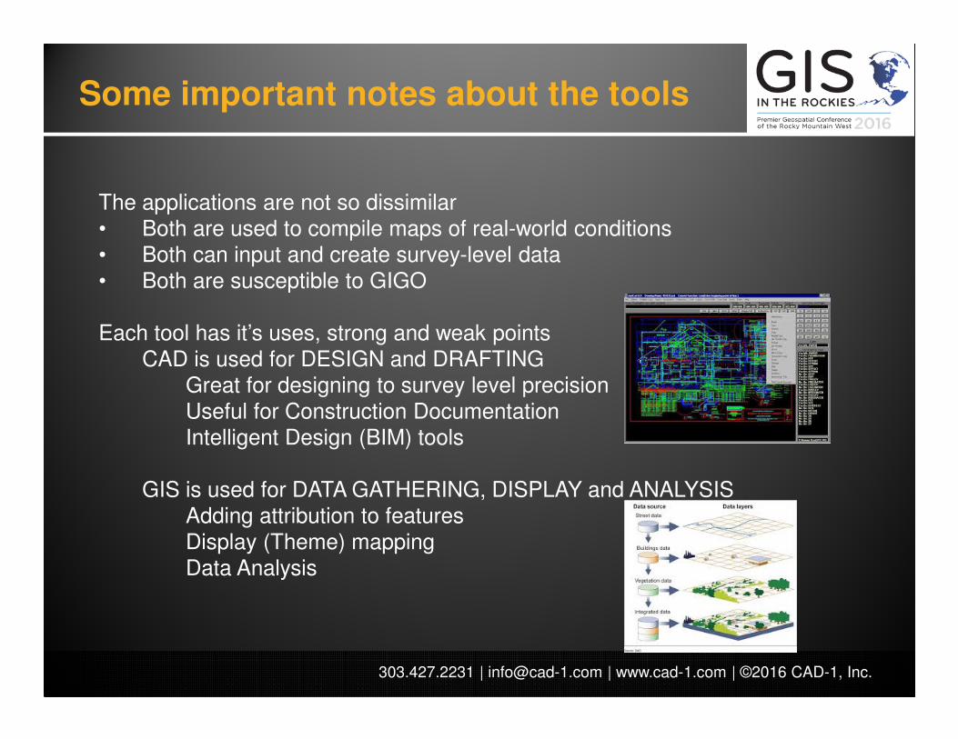
The applications are not so dissimilar
• Both are used to compile maps of real-world conditions• Both can input and create survey-level data• Both are susceptible to GIGO
Each tool has it’s uses, strong and weak points
CAD is used for DESIGN and DRAFTING
Great for designing to survey level precisionUseful for Construction Documentation
Intelligent Design (BIM) tools
GIS is used for DATA GATHERING, DISPLAY and ANALYSIS
Adding attribution to features
Display (Theme) mappingData Analysis
Some important notes about the tools
303.427.2231 | [email protected] | www.cad-1.com | ©2016 CAD-1, Inc.
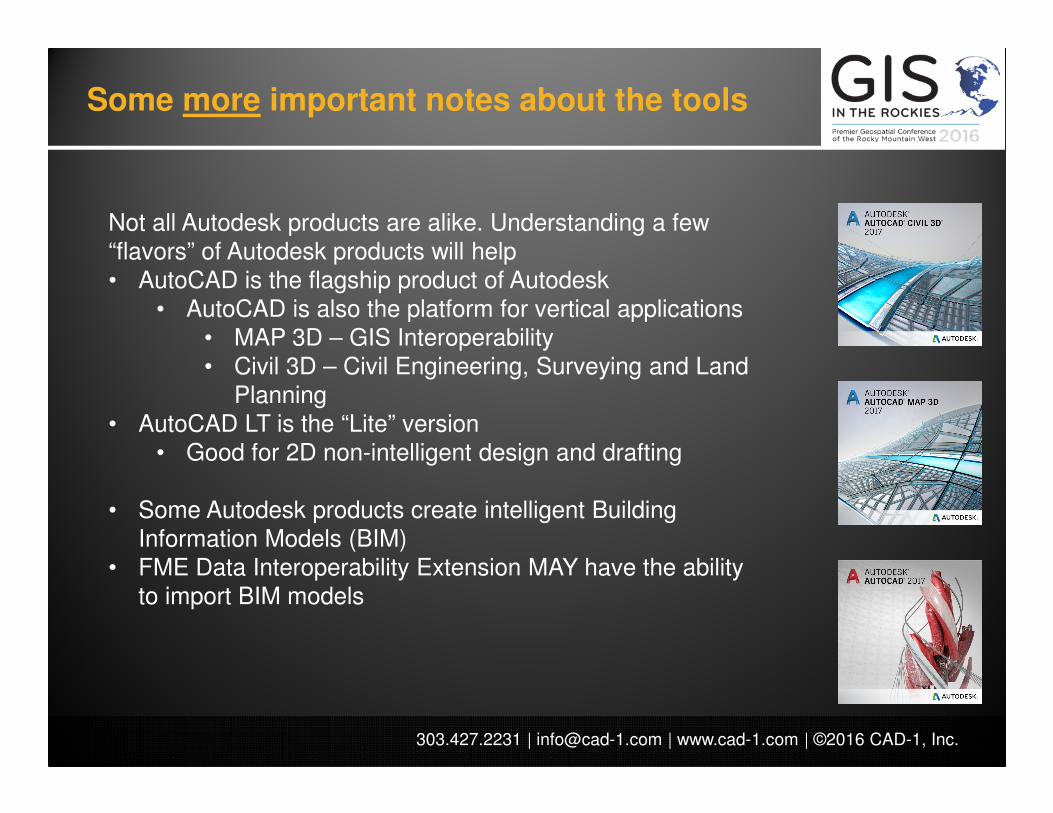
Not all Autodesk products are alike. Understanding a few
“flavors” of Autodesk products will help• AutoCAD is the flagship product of Autodesk
• AutoCAD is also the platform for vertical applications
• MAP 3D – GIS Interoperability
• Civil 3D – Civil Engineering, Surveying and Land
Planning
• AutoCAD LT is the “Lite” version• Good for 2D non-intelligent design and drafting
• Some Autodesk products create intelligent Building Information Models (BIM)
• FME Data Interoperability Extension MAY have the ability
to import BIM models
Some more important notes about the tools

303.427.2231 | [email protected] | www.cad-1.com | ©2016 CAD-1, Inc.
A note on software versions
• AutoCAD file format = .dwg• The drawing file format has historically (and will continue to) evolved to allow for more features• Versions are always upward compatible – but not downward compatible• ESRI software may not be compatible with the latest format of AutoCAD .dwg
• ESRI Software may not be compatible with the version of AutoCAD saving the file
• AutoCAD 2000 dwg format
• AutoCAD 2000, 2000i, 2002
• AutoCAD 2004 dwg format
• AutoCAD 2004, 2005, 2006
• AutoCAD 2007 dwg format
• AutoCAD 2007, 2008, 2009
• AutoCAD 2010 dwg format
• AutoCAD 2010, 2011, 2012
• AutoCAD 2013 dwg format
• AutoCAD 2013, 2014, 2015, 2016, 2017

303.427.2231 | [email protected] | www.cad-1.com | ©2016 CAD-1, Inc.
In order to better integrate these two industries you need to learn how to speak
both languages. Missteps could lead to wrong datasets, incorrectly geo-referenced
files, bad decision making and wasted resources.
BASIC TERMS:
On to the definitions…
Data Store - A collection of feature data in a single storage location (a file or database such as Oracle). [AutoCAD=DRAWING]
Feature Class - A category of features with rules that define the allowable data types, default values, and constraints for its member features. For example, you might have feature classes for a set of roads, utility poles, and so on. [AutoCAD=LAYER with no color or linetype]
Schema – A schema is the structure of the database that defines the objects in the database. [AutoCAD=Drawing Template with predefined layers, styles, etc.]
Feature - The spatial representation of a real-world entity, such as a specific road or an individual utility pole, that specifies the geometry and other properties of the feature [AutoCAD=ENTITY]
For example, you might use a data store such as Oracle, which can encompass multiple schemas. The database might define the utilities for a town, with schemas for different types of utilities, such as electrical and water. The electrical schema would include feature classes for utility poles and boxes, while the water schema would include feature classes for pipes and hydrants, each feature class would contain one or more features.
303.427.2231 | [email protected] | www.cad-1.com | ©2016 CAD-1, Inc.
More definitions…
Feature Type – GIS supports three distinct feature types – Point (Node), Line (Curve) and Polygon (Surface). Points are any feature defined by one location (text, hatch, blocks). Polygons must be closed areas defined by one object. Only a few datastores will allow multiple feature types in one database.
Spatial Database – Any database type (Oracle, SQL, Access, etc) that can store spatial data (lines)
Enterprise Database – Large database type which allows for multiple-user access (via versioning) and management. (Oracle, SQL Server)
Layer – A Feature Class with stylization applied.[AutoCAD=LAYER with color and linetype assigned]
Attribute – A property of a feature (manhole type, road width) [AutoCAD=ATTRIBUTE or TEXT LABEL]
Metadata – Information about a GIS database (coordinate system, attribute definitions, etc.) typically held in an HTML or XML document.
Version – A file which maintains a list of all of the edits made to a GIS datastore (by a particular person.) The datastore is not updated until all of the versions are “checked in”. Versions are incorporated into the datastore through rules.
Constraints / Domains – Drop-down lists for adding attributes.
Transform – The act of moving an existing map to a known coordinate system. Typically this involves moving, rotating, and sometimes scaling of the existing map. Two known coordinates (or locations) are required. (This term is often mixed up with Translate)
Translate – The act of moving data from a datastore from one coordinate system into another. Unlike transform (above) this requires a high level of math to shift each node of the data from one coordinate to another. (This term is often mixed up with Transform)
303.427.2231 | [email protected] | www.cad-1.com | ©2016 CAD-1, Inc.
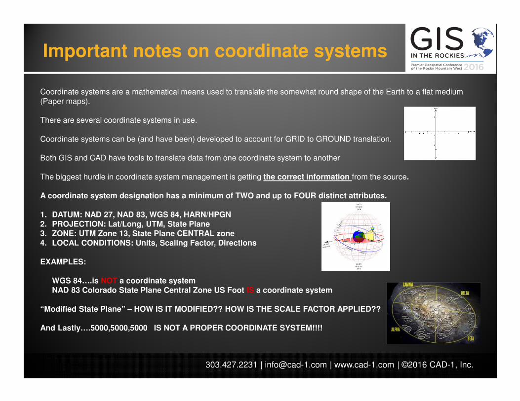
Important notes on coordinate systems
Coordinate systems are a mathematical means used to translate the somewhat round shape of the Earth to a flat medium (Paper maps).
There are several coordinate systems in use.
Coordinate systems can be (and have been) developed to account for GRID to GROUND translation.
Both GIS and CAD have tools to translate data from one coordinate system to another
The biggest hurdle in coordinate system management is getting the correct information from the source.
A coordinate system designation has a minimum of TWO and up to FOUR distinct attributes.
1. DATUM: NAD 27, NAD 83, WGS 84, HARN/HPGN2. PROJECTION: Lat/Long, UTM, State Plane3. ZONE: UTM Zone 13, State Plane CENTRAL zone4. LOCAL CONDITIONS: Units, Scaling Factor, Directions
EXAMPLES:
WGS 84….is NOT a coordinate systemNAD 83 Colorado State Plane Central Zone US Foot IS a coordinate system
“Modified State Plane” – HOW IS IT MODIFIED?? HOW IS THE SCALE FACTOR APPLIED??
And Lastly….5000,5000,5000 IS NOT A PROPER COORDINATE SYSTEM!!!!

303.427.2231 | [email protected] | www.cad-1.com
Award Winning CAD-1 Services
•Classroom Training – for upcoming schedule, visit www.cad-1.com
•Custom, In-Person, Mentoring Programs – training programs tailored to your firm’s specific needs.
•Implementation– Assisting you in the addition of new software and workflows into your organization
•Online Mentoring – Live mentoring and problem solving assistance delivered over the web.
•Online Training– Live training delivered via web just like classroom training. All you need is an Internet connection.
•Support – Excellent Telephone Support from CAD-1 Can Now be Combined with Web Based Tools for Fast Problem Resolution..
Call CAD-1 at 303-427-2231 for More Information on These Services

303.427.2231 | [email protected] | www.cad-1.com
If you would like more information about
the content provided here today, please contact us at:
303-427-2231 (Office)