20
VarioSpray Nozzle valve systems for variable atomization of very small liquid volumes

VarioSprayNozzle valve systems for variable atomization of very small liquid volumes

2
Lechler is a world leader in nozzle technology. For over 135 years, we have pioneered numerous
groundbreaking developments in the fi eld of nozzle technology. We combine comprehensive
nozzle engineering expertise with a deep understanding of application-specifi c requirements to
create products that o� er outstanding performance and reliability.
Innovative and fl exible spraying technology opens up new applications
Faster, more precise and now more sustainable. The demand for more e� cient production processes is increasing in almost every industry. Even already extremely e� cient spraying processes are a� ected – particularly when spraying very small liquid volumes.
Pneumatic atomizing systems are often used here because very small fl ow rates can be achieved using compressed air. However, this often makes control and installation extremely complex.
FULL DOSAGE CONTROL FOR MAXIMUM COST CONTROL
Additionally, the use of air can have an unfavorable e� ect on operating costs. Aerosols may also be formed and liquid is lost due to the rebound e� ect.
With the VarioSpray II and VarioSpray HP hydraulic pulse-width-modulated nozzle valve systems, Lechler o� ers two alternatives that are as versatile as they are reliable.With hydraulic nozzle sys-tems, the narrowest cross section of the spray nozzle determines the liquid fl ow rate. For reasons of economy and production, however, arbitrary reduction of this narrowest cross section is not possible.
Instead, we use fl exible timing of the spray duration to realize minimal fl ow rates – without the need for an expensive and complex pneumatic atomizing system.
In addition to the VarioSpray II and VarioSpray HP nozzle valve systems, a control unit is also required to permit sim-ple modifi cation of the pulse width and cycle frequency.
Your benefi ts Simple adjustment of the pulse width and cycle frequency Flushing function Modular design and modular system Start/stop signal (e.g. via light barrier) Individual valve control for VarioSpray HP

3
BENEFITS ACROSS THE BOARD
FLEXIBILITY
The Lechler VarioSpray system is completely modular, allowing it to be adapted to individual requirements as fl exibly as possible.
The result is a perfectly coordinated product portfolio including Optimum valve control by per-fectly matched electronic compo-nents
Modular spray headers
Various predefi ned Lechler control concepts
Individual advice from our sales personnel
RESOURCE AND COST SAVINGS
The aerosol-free atomization of small and minimal liquid volumes o� ers specifi c benefi ts for spray nozzle operation. The fact that no atomization air is used means a huge reduction in rebound e� ects.
The following costs are reduced as a result:
Installation cleaning
Operating costs of extraction systems
Liquid losses because the liq-uid to be atomized is applied to the product in a more targeted manner
MINIMAL AMOUNTS
Thanks to the use of pulse-width-modu-lated valves, even the smallest liquid quantities can be hydraulically atomized with maximum precision.
This control method permits
fl exible and immediate response to changed ambient parameters (e. g. belt speed)
uniform jet and spray quality
further application benefi ts due to a signifi cantly increased turn-down ratio

4
TECHNICAL BACKGROUND
Pulse width modulation refers to the variation of the ON time ton / OFF time to� of a square-wave signal when thefrequency f remains constant. Here, the frequency f corre-sponds to the reciprocal value of the period duration T.
The ratio of the ON time ton to the period duration T is referred to as the pulse width ratio (DC = duty cycle). The pulse width ratio determines the flow rate. The valve is open during the ON time ton.The shorter the DC, the less the flow rate.
Depending on the frequency selected, the pulsation is barely visible to the human eye.
The two innovative Lechler products VarioSpray II and VarioSpray HP can be used to precisely spray a wide range of di�erent liquids. The two nozzle valve systems are indivi-dually designed to optimally perform these tasks.
VarioSpray II is ideal for applying small volumes of low-viscosity, easily atomized liquids.
Pulse width ratio 90%
t on
t off
T
Pulse width ratio 10%
t on
t off
T
� �
Pulse width ratio 90%
t on
t off
T
Pulse width ratio 10%
t on
t off
T
� �
What is pulse width modulation?
What fluids can be sprayed?
VarioSpray HP was devel-oped to permit flexible spraying of a wide variety of liquids. Even high-viscosity media (up to 75 mPas, depending on the liquid density) can be easily atomized.
Possible liquids for VarioSpray:
VarioSpray II VarioSpray HP
Water
Low-viscosity release agent
Disinfectant
– Oils
– Fats
– Emulsions
– Liquid egg
– Milk
– Sugar solutions
– etc.

5
8 GOOD REASONS FOR GREATER COST EFFICIENCY
Minimum flow rates– Liquid saving– No expensive, complex twin-fluid system
Reduced costs Greater e�ciency
Increased productivity Shorter production time
More flexible production
Shorter product changeover times
Constant process parameters
Short installation time Low maintenance requirement Low operating costs
Reduced risks to health No environmental pollution Reduced costs
Compliance with legal requirements
Cycle frequency up to 200 Hz for VarioSpray HP, up to100 Hz for VarioSpray II- Flexible belt speeds
High turn-down ratio up to 29:1 29:1 with VarioSpray HP, up to 11:1 with VarioSpray II– Wide range of flow rates covered by one nozzle
Continuously variable flow rate– Flexible adjustment of the volume applied for
di�erent products
Di�erent flow rates have no influence on spraying parameters– Constant spray angle– Uniform droplet size
Flow rate is not regulated by pressure– No high pressure required– Simple setup
No atomization air– No aerosol formation– Reduced loss of liquid
Food-compliant– Spraying/humidification of foods
Product features Your benefit

6
POSSIBLE APPLICATIONS FOR VarioSpray HP
Application of oil for applying seasonings
Oils are generally applied so that products can adhere (e.g. seasonings to cereals/snacks). With VarioSpray HP, this can be performed without aerosols. This means a signifi cant reduction in operating costs and the necessary cleaning pro-cesses.
Web humidifi cation
Individual valve con-trols permit fl exible response to changes in product moisture (for example, on paper webs or non-woven fabrics) and improve-ments in product quality.
Coating of foods
With VarioSpray HP, commonly used liquids such as sugar solutions containing vitamins or liquid egg can be e� -ciently sprayed onto the product with practically no loss.
Release agent application for more viscous media
The application of demolding oils, anti-corrosion agents, or other release agents often requires costly extraction sys-tems. With VarioSpray HP, these systems can be kept to a minimum or even eliminated altogether. At the same time, the media is more evenly applied to the product.
Optimization of the production process
Moisture loss resulting from freezing can be precisely compensated by applying water. You will notice immediate, measurable success in the optimization of your production processes.

7
POSSIBLE APPLICATIONS FOR VarioSpray II
Anti-scu¢ ng
The application of anti-scu� ng lubricants reduces wear rings while at the same time reducing lubricant consumption as com-pared to conventional application methods.
Disinfection
Targeted, pulse-width-modulated application of antibacterial liquids to a variety of systems/products for purposes of disinfection reduces liquid consumption, while also ensuring maximum safety and compliance with hygiene guidelines.
Release agent application for low-viscosity media
For solidifying and improving the quality of surfaces by means of low-viscosity media, e.g. before the press process.
Humidifi cation of dough products
Dough products are humidifi ed to maintain the stability of the production processes. Small amounts must be precisely sprayed onto the dough products. VarioSpray II allows material losses to be greatly minimized.
Coating with VarioSpray II
Coating and metering process-es are commonly used in food processing. The VarioSpray II pulse-width-modulated nozzle valve system is impressively fl exible, making it possible to spray the smallest liquid volumes with precision.

8
VarioSpray HP
The HP valve range can be used to atomize a wide variety of liquids. All parts that come into contact with liquids are made of stainless steel, thereby complying with EC 1935/2004 and FDA regulations.
* Depending on the density of the liquid
Valve 752.060.1Y.00 752.090.1Y.00
Type 2/2-way N.C. 2/2-way N.C.
Nominal diameter 0.6 mm 0.9 mm
Pressure range 10 bar 7 bar
Voltage 12 V DC
Nominal power 9 W
Control Peak & Hold Control only
Housing material 316L SS
Spring material 301 SS
Protection type IP 65
Frequency 0 – 200 Hz
Hose connection Push-in dia. 8 mm
Electrical connection M8 3-pin circular connector
Suitable for the following viscosities in mPas*
0 10 20 30 40 50 60 70 80Ordering no.:752.060.1Y.00
90
0 10 20 30 40 50 60 70 80Ordering no.:752.090.1Y.00
90

9
Control of the VarioSpray HP valve is based on the peak & hold principle. The required voltage signal is also generated according to the PWM* principle.This method results in short response times and energy-e�cient valve control, which also results in minimal heat generation in the magnetic coil. Typical peak-and-hold parameters, depending on the operating pressure and medium:tpeak: 500-1000 µs Vpeak: 16-28 V Vhold: 2.0-5.6 V
1 2 3 4 5 6 7 8 9 1000
4
8
12
16
20
24
U[V]
11 12t[ms]
Voltage at VarioSpray HP valve coil, Peak-and-Hold principleduty cycle of VarioSpray HP valve, PWM modulated, here as an example at 100 Hz operating frequecy and 50 % duty cycle
Voltage at power amplifier output, PWM modulated
Valveclosed
Valve open
Ø 36.5
18
Ø 4.1
11
2.1
12.3
14
32
25.5
8539
Ø 36.5
18
Ø 4.1
11
2.1
12.3
14
32
25.5
8539
Spray angle**
Ordering no.
MaterialSuitable for valves
Flow rate range***
16 17 56 l/min l/min
303
SS
316T
i SS
/ 31
6L S
S
PO
M
752.060.1Y 752.090.1Y 752.060.1Y 752.090.1Y
60° 652.304.WW.05 – – – 0.09 – 0.55
652.334.WW.05 – – – 0.11 – 0.71
652.364.WW.05 – – – 0.13 – 0.91
75° 652.145.WW.05 – 0.02 – 0.10 0.02 – 0.10
652.165.WW.05 – – 0.02 – 0.12 0.02 – 0.12
652.185.WW.05 – 0.02 – 0.15 0.03 – 0.16
652.215.WW.05 – – 0.03 – 0.19 0.04 – 0.20
652.245.WW.05 – – 0.04 – 0.26 0.05 – 0.28
652.275.WW.05 – – 0.05 – 0.34 0.07 – 0.38
90° 652.216.WW.05 – – 0.03 – 0.19 0.04 – 0.20
652.246.WW.05 – – 0.04 – 0.30 0.06 – 0.33
652.276.WW.05 – – 0.05 – 0.35 0.07 – 0.40
652.306.WW.05 – – – 0.09 – 0.59
652.336.WW.05 – – – 0.11 – 0.72
652.366.WW.05 – – – 0.13 – 0.92
120° 652.187.WW.05 – – 0.02 – 0.14 0.03 – 0.15
652.217.WW.05 – – 0.03 – 0.20 0.04 – 0.21
652.247.WW.05 – – 0.04 – 0.29 0.05 – 0.31
652.277.WW.05 – – 0.05 – 0.36 0.07 – 0.41
652.307.WW.05 – – – – 0.09 – 0.58
652.337.WW.05 – – – 0.11 – 0.73
652.367.WW.05 – – – 0.13 – 0.95
* PWM: Pulse width modulation ** Spray angle can di�er in PWM operation*** DC: 10 – 90 %, fluid pressure: 4 – 7 bar, frequency: 50 Hz, DC = Pulse width ratio %

10
VarioSpray II
Nozzle valves in the VarioSpray II range can e� ciently atomize the most miniscule liquid volumes. Their size makes these valves ideal for use in tight spaces. VarioSpray II is also available in a food version that complies with EC 1935/2004 and FDA regulations.
Valve 742.030.1Y. 742.050.1Y.00 742.050.1Y.10
Type 2/2-way N.C.
Nominal diameter 0.3 mm 0.5 mm 0.5 mm
Pressure range 0 – 10 bar 0 – 8 bar 0 – 8 bar
Voltage 24 V DC
Nominal power 2 W
Sealing material FPM
Housing material 316L SS
Spring material 301 SS
Coil resistance 288 ohms
Protection type IP 65
Frequency 0 – 100 Hz
Hose connection Ø 6 x 1 mm
Suitable for the following viscosities in mPas*
0
0
5
5
10
10
15
15
20
20
25
25
30
30
35
35
40
40
Ordering no.: 742.030.1Y.
Ordering no.: 742.050.1Y.00/10
45
45
* Depending on the density of the liquid
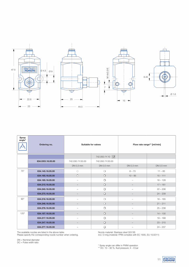
11
The available nozzles are listed in the above table. Please specify the corresponding nozzle number when ordering.
DN = Nominal diameterDC = Pulse width ratio
Nozzle material: Stainless steel 303 SSincl. O-ring (material: FPM complies with EC 1935, EU 10/2011)
* Spray angle can di�er in PWM operation** DC: 10 – 90 %, fluid pressure: 4 – 6 bar
Spray angle*
Ordering no. Suitable for valves Flow rate range** [ml/min]
742.050.1Y.10
634.XXX.16.05.00 742.030.1Y.00.00 742.050.1Y.00.00
DN 0.3 mm DN 0.5 mm DN 0.3 mm DN 0.5 mm
75° 634.145.16.05.00 8 – 73 11 – 85
634.165.16.05.00 10 – 85 15 – 111
634.185.16.05.00 – – 16 – 128
634.215.16.05.00 – – 17 – 161
634.245.16.05.00 – – 22 – 206
634.275.16.05.00 – – 24 – 239
90° 634.216.16.05.00 – – 18 – 165
634.246.16.05.00 – – 21 – 211
634.276.16.05.00 – – 25 – 238
120° 634.187.16.05.00 – – 14 – 130
634.217.16.05.00 – – 19 – 168
634.247.16.05.00 – – 23 – 215
634.277.16.05.00 – – 24 – 237
8.45
Ø 1.6
47.5
22.6
25
25
44.5
7
15
M 4
x3.5
/6
Ø 4.5 Ø 9
8.45
Ø 1.6
47.5
22.6
25
25
44.5
7
15
M 4
x3.5
/6
Ø 4.5 Ø 9
8.45
Ø 1.6
47.5
22.6
25
25
44.5
7
15
M 4
x3.5
/6
Ø 4.5 Ø 9
8.45
Ø 1.6
47.5
22.6
25
25
44.5
7
15
M 4
x3.5
/6
Ø 4.5 Ø 9

12
Single valve
COMPONENTS AND COMBINATION OPTIONSVarioSpray HP
Single valve
Combination example
�
�
�
�
�
�
�
�
�
�
�
�

13
COMPONENTS AND COMBINATIONS
Version No. Description Ordering no. Technical specification Length
Valves
�Valve, incl. retaining nut, connecting nipple, packaging, manual, O-ring FDA-compliant
752.060.1Y.00 DN 0.6 mm; 12 V, peak-and-hold control; for further technical data see Page 8/9
�Valve, incl. retaining nut, connecting nipple, packaging, manual, FDA-com-pliant
752.090.1Y.00 DN 0.9 mm; 12 V, peak-and-hold control; for further technical data see Page 8/9
Basic analog control
Siemens S7-1200 controller for control cabinet installation, incl. pre-installed software package
075.270.00.00 on USB stick, control: Siemens S7 1200 / control of up to 16 valves, all valves switched simultaneously
Power driver 075.281.00.00 max. 4 valves per power driver
SMART control � SMART control 075.270.00.10 Control unit for up to 8 VarioSpray HP valves, simultaneous switching of all valves, see Page 18 for technical details
FLEX control � FLEX control 075.270.00.20 Control unit for up to 16 VarioSpray HP valves, individual valve control possible, see Page 18 for technical details
Components for VarioSpray HP
� Nozzle 652.XXX.WW.05 See Page 9 for possible sizes
� Valve cable, M8 - M8 075.280.00.00 Retaining nut, material: 316L SS 5 m
� Valve cable, M8 - M8 075.280.00.01 Retaining nut, material: 316L SS 10 m
Valve filter 075.250.1Y.00 Mesh size: 80 µm, max. pressure 10 bar, material: 316L SS/Viton/adhesive-free, connection: 1/8 BSPP x 1/8 BSPP
� Filter for central liquid line 074.217.1Y.00 for up to 8 valves** / Mesh size: 40 µm, max. pressure 10 bar, material: 316L SS/Viton/adhesive-free, connection: 3/8 BSPP
� ITEM profile, 80 x 40 074.215.40.00 incl. T-slot nuts, screws, caps, universal holder, Material: Aluminum 1 m
� ITEM profile, 80 x 40 074.215.40.01 incl. T-slot nuts, screws, caps, universal holder, Material: Aluminum 2 m
� Central liquid supply line* 075.290.00.00 Hose dia. 22, material: LLDPE blue 10 m
� Valve hose to the valves 074.213.54.01 Hose dia. 8, material: LLDPE natural 5 m
� Hose fitting set 075.290.56.50 set components: reducing tee (22 x 22 x 15) 2 x reducer (15 x 12 and 12 x 8); material: POM
� Ventilation set 075.290.56.51 set components: reducing tee (22 x 22 x 15; 2 x reducer (15 x 12 and 12 x 8); 1 x shut-o� valve; 1 x plug; material: POM
� Tube clamp 075.230.00.10 for hose dia. 22
Backflush nipple 075.210.1Y.00 G 3/8 on hose dia. 8 mm, material: 316L SS
Expansion set for valve mounting 075.230.00.00 T-slot nuts (25 ea), screws (16 ea. M4 x 30), universal holders (10 ea.)
Ordering information
The above table shows the VarioSpray HP versions recommended by Lechler.Please specify the required individual components when ordering.
The available nozzles are listed in the table on Page 9. Please specify the corresponding nozzle number when ordering.
DN = Nominal diameter
* FDA-compliant, EC 1935/10/2011 on request ** Other filters on request
Questionnaire:www.lechler.de/variospray/fragebogen_variospraywww.lechler.com/variospray/questionnaire_variospray

14
Single valve
COMPONENTS AND COMBINATION OPTIONS VarioSpray II
Ordering information
The adjacent table shows the VarioSpray II versions recommended by Lechler.The possible combinations are highlighted in color and are visually represented in the table »Components and combinations«. Please specify the required individual components when ordering.
The liquid supply lines are available in the materials 5N (polyamide) or 5F (polyurethane).
Please replace »WW« in the order number with the required material.
The available nozzles are shown in theadjacent table. Please specify the correspondingnozzle number when ordering.
DN = Nominal diameter
Assembly tool
Combination example forversions B, C and D

15
COMPONENTS AND COMBINATIONS
Version No. Description Ordering no. Qty. Technical specification Length
A
� Valve, incl. hollow core screw 742.030.1Y.00.00 DN 0.3 mm, see technical data for further information
Valve, incl. hollow core screw 742.050.1Y.00.00 DN 0.5 mm, see technical data for further information
� Nozzle 634.XXX.16.05.00 See nozzle overview
� Valve cable, M8, open 074.211.00.00.00 Cable length: 2 m
Valve cable, M8, open 074.211.00.01.00 Cable length: 5 m
� Assembly tool 074.290.30.00.00 1 For flat spray nozzle, material: Brass
� Filter 074.217.1Y.00.00 1 Mesh size: 40 µm, max. pressure: 10 bar, material: 316L SS, connection: 3/8 BSPP
B
� Valve, incl. hollow core screw 742.030.1Y.00.00 max. 8 DN 0.3 mm, see technical data for further information
Valve, incl. hollow core screw 742.050.1Y.00.00 max. 8 DN 0.5 mm, see technical data for further information
� Nozzle 634.XXX.16.05.00 max. 8 See nozzle overview
� Valve cable, M12 – M8 074.210.00.00.00 max. 8 With bus connector, supplied loose 1 m
� Control, table version 074.200.00.00.00 1 Incl. bus cable, bus cable end cap, instructions for use and quick start instructions 10 m
� Hose, dia. 6 x 1 mm 074.212.WW.00.00 1 Valve supply line, for up to 4 valves, material: 5N (polyamide) or 5F (polyurethane) 1.5 m
Hose, dia. 6 x 1 mm 074.212.WW.01.00 1 Valve supply line, for up to 8 valves, material: 5N (polyamide) or 5F (polyurethane) 2.5 m
Wall bracket for control 074.257.00.00.00 1 Mounting set for wall installation of control
Rubber feet, self-adhesive 074.258.00.00.00 1 4 ea., black, for control
� Assembly tool 074.290.30.00.00 1 For flat spray nozzle, material: Brass
� Filter 074.217.1Y.00.00 1 Mesh size: 40 µm, max. pressure: 10 bar, material: 316L SS, connection: 3/8 BSPP
C
� Valve, incl. hollow core screw 742.030.1Y.00.00 max. 8 DN 0.3 mm, see technical data for further information
Valve, incl. hollow core screw 742.050.1Y.00.00 max. 8 DN 0.5 mm, see technical data for further information
� Nozzle 634.XXX.16.05.00 max. 8 See nozzle overview
� Valve cable, M12 – M8 074.210.00.00.00 max. 8 With bus connector, supplied loose 1 m
� Control, table version 074.200.00.00.00 1 Incl. bus cable, bus cable end cap, instructions for use and quick start instructions 10 m
� Hose, dia. 6 x 1 mm 074.212.WW.00.00 1 Valve supply line, for up to 4 valves, material: 5N (polyamide) or 5F (polyurethane) 1.5 m
Hose, dia. 6 x 1 mm 074.212.WW.01.00 1 Valve supply line, for up to 8 valves, material: 5N (polyamide) or 5F (polyurethane) 2.5 m
� Hose, dia. 8 x 1.25 mm 074.213.WW.00.00 1 Central liquid line, material: 5N (polyamide) or 5F (polyurethane) 3 m
Hose, dia. 8 x 1.25 mm 074.213.WW.01.00 1 Central liquid line, material: 5N (polyamide) or 5F (polyurethane) 5 m
� Reducing tee 074.214.00.00.00 max. 8 dia. 8 to dia. 6 mm
� Ventilation 074.216.00.00.00 1 Ball valve with threaded stud
Wall bracket for control 074.257.00.00.00 1 Mounting set for wall installation of control
Rubber feet, self-adhesive 074.258.00.00.00 1 4 ea., black, for control
� Assembly tool 074.290.30.00.00 1 For flat spray nozzle, material: Brass
� Filter 074.217.1Y.00.00 1 Mesh size: 40 µm, max. pressure: 10 bar, material: 316L SS, connection: 3/8 BSPP
D
� Valve, incl. hollow core screw 742.030.1Y.00.00 max. 8 DN 0.3 mm, see technical data for further information
Valve, incl. hollow core screw 742.050.1Y.00.00 max. 8 DN 0.5 mm, see technical data for further information
� Nozzle 634.XXX.16.05.00 max. 8 See nozzle overview
� Valve cable, M12 – M8 074.210.00.00.00 max. 8 With bus connector, supplied loose 1 m
� Control, table version 074.200.00.00.00 1 Incl. bus cable, bus cable end cap, instructions for use and quick start instructions 10 m
� Hose, dia. 6 x 1 mm 074.212.WW.00.00 1 Valve supply line, for up to 4 valves, material: 5N (polyamide) or 5F (polyurethane) 1.5 m
Hose, dia. 6 x 1 mm 074.212.WW.01.00 1 Valve supply line, for up to 8 valves, material: 5N (polyamide) or 5F (polyurethane) 2.5 m
� Hose, dia. 8 x 1.25 mm 074.213.WW.00.00 1 Central liquid line, material: 5N (polyamide) or 5F (polyurethane) 3 m
Hose, dia. 8 x 1.25 mm 074.213.WW.01.00 1 Central liquid line, material: 5N (polyamide) or 5F (polyurethane) 5 m
� Reducing tee 074.214.00.00.00 max. 8 dia. 8 to dia. 6 mm
� ITEM profile, 80 x 40 mm 074.215.40.00.00 1 incl. T-slot nuts, screws, caps, universal holder; material: Aluminum 1 m
ITEM profile, 80 x 40 mm 074.215.40.01.00 1 incl. T-slot nuts, screws, caps, universal holder; material: Aluminum 2 m
� Ventilation 074.216.00.00.00 1 Ball valve with threaded stud
Wall bracket for control 074.257.00.00.00 1 Mounting set for wall installation of control
Rubber feet, self-adhesive 074.258.00.00.00 1 4 ea., black, for control
� Assembly tool 074.290.30.00.00 1 For flat spray nozzle, material: Brass
� Filter 074.217.1Y.00.00 1 Mesh size: 40 µm, max. pressure: 10 bar, material: 316L SS, connection: 3/8 BSPP
WW = code for material: 5N (polyamide) 5F (polyurethane)
Questionnairewww.lechler.de/variospray/fragebogen_variospraywww.lechler.com/variospray/questionnaire_variospray

16
FOOD-COMPLIANTVarioSpray II COMPONENTS
The products listed below comply with the requirements of (EC) No. 1935/2004 for food contact materials as well as the regulations of the Food and Drug Admin-istration (FDA) for repeated food contact.
* Components can also be used for VarioSpray HP
The other components which are not in direct contact with the food are listed in the table on Page 4.
Ordering no. Designation Further information Technical information Material
074.212.54.00.00 Hose, 6 x 1 Valve supply line 1.5 m LLDPE natural
074.212.54.01.00 Hose, 6 x 1 Valve supply line 2.5 m LLDPE natural
074.213.54.00.00 Hose, 8 x 1* Central liquid line 3 m LLDPE natural
074.213.54.01.00 Hose, 8 x 1* Central liquid line 5 m LLDPE natural
074.214.00.01.00 Equal tee 8 x 8 – 8 x 8 POM
074.214.00.02.00 Reducer 8 x 6 POM
074.216.00.01.00 Ventilation* Shut-o� valve with push-in fi tting dia. 8 mm PP
074.253.00.01.00 Valve cable, M12 – M8 0.3 m PVC / EPDM / 316L SS
074.254.00.00.06 Hose clamp Packaging unit 5 ea. LLDPE
074.217.1Y.00.00 Line fi lter* G 3/8 – 40 µm 1.4404

17
COMPARISON VarioSpray HP – VarioSpray II
* Nominal fl ow rate without nozzle
Flow rate: up to 1 l/min at 3 bar*
For viscous media up to 75 mPas
Liquid supply at the rear
Flow-optimized liquid supply
Simple nozzle changes
Turn-down ratio up to 29:1
Filter optional
Push-in connection for dia. 8 hose
Voltage: 12 V DC
Electrical connection via M8 push-in fi tting
Control via color touch panel
Two control unit versions
– SMART (max. 8 valves)
– FLEX (max. 16 valves)
Individual valve control (FLEX)
Frequencies: 10/20/30/40/50/75/100/200 Hz
Flow rate: up to 140 ml/min at 3 bar*
For low-viscosity media up to 15 mPas
Liquid supply at the side
Low liquid volume in the valve
Very small design
Turn-down ratio up to 11:1
Integrated last-chance fi lter
Push-on connection for dia. 6 x 1 hose
Voltage: 24 V DC
M8 push-in fi tting
Compact control unit
Simple operation
(max. 8 valves)
All valves simultaneously
Frequencies: 25/50/75/100 Hz

18
Control unit for VarioSpray HP
The two VarioSpray HP control unit versions with clearly understandable color displays permit optimal valve control in line with your requirements.
SMART
The SMART valve control unit is an economical version for valves in the HP range. It permits simultaneous control of all valves for easy operation.
Benefi ts: Easy operation Simultaneous control of all connected valves Control software ideally matched to the valves Clear 4.3" color touch display 4 direct control buttons for fast access
FLEX
The FLEX control unit is char-acterized by fl exibility – the VarioSpray HP valves can be controlled and the fl ow rate regulated individually. This feature is ideal for applica-tions in which di� erent belt widths occur in the produc-tion process. Benefi ts: Straightforward operation Individual control of all valves via software switches Control software ideally matched to the valves Clear 4.3" color touch display 4 direct control buttons for fast access
SMART FLEX
Maximum number of valves 8 16
Individual valve control No Yes
Frequency 10 / 20 / 30 / 40 / 50 / 75 / 100 / 200 Hz
Supply voltage 100 – 240 V AC
Total power 240 W
Control voltage 12 – 24 V DC / Peak-and-hold control
Pulse width 3 – 98 %
Lag time 0 – 99.9 s
Lead time 0 – 99.9 s
External signal input Yes
Protection type IP 54
Display 4.3" color touch panel
Electrical connection for valves M8 3-pin circular connector
Ordering data Ordering no.Control unit SMART 075.270.00.10Control unit FLEX 075.270.00.20
300
400
155

19
Control unit for VarioSpray II
The control unit permits opti-mal operation of the nozzle valves from the VarioSpray II series.
The control elements are kept to a minimum and allow easy operation.
Benefi ts: Easy operation Simultaneous control of all connected valves Compact dimensions Software ideally matched to the valves Valve connection via a central bus line
Maximum number of valves 8
Supply voltage 115 – 230 V AC
Control voltage 24 V DC
Total power 20 W
Frequency 25 / 50 / 75 / 100 Hz
Pulse width 0 – 90 / 100 %
Lag time 0 – 10 s
External signal input Yes
Protection type IP 54
Ordering data Ordering no.Control unit VarioSpray II 074.200.00.00.00.0
188
244
58

Ed
itio
n 04
/17
· EN
· 50
0 · M
-201
7-35
50-0
57 ·
ww
w.d
gm-w
allis
er.d
e · S
· S
ubje
ct to
tech
nica
l mod
ifica
tion.
Lechler GmbH · Precision Nozzles · Nozzle SystemsP.O. Box 13 23 · 72544 Metzingen, Germany · Phone: +49 7123 962-0 · Fax: +49 7123 962-333 · [email protected] · www.lechler.com
Belgium: Lechler S.A./N.V. · Avenue Mercatorlaan, 6 · 1300 Wavre · Phone: +32 10 225022 · Fax: +32 10 243901 · [email protected]: Lechler Intl. Trad. Co. Ltd. · Beijing · Rm. 418 Landmark Tower · No. 8 Dong San Huan Bei Lu · Phone: +86 10 84537968, Fax: +86 10 84537458 · [email protected]: Lechler Oy · Jäspilänkatu 18 · 04250 Kerava · Phone: +358 207 856880 · Fax: +358 207 856881 · [email protected]: Lechler France, S.A. · Bât. CAP2 · 66-72, Rue Marceau · 93558 Montreuil cedex · Phone: +33 1 49882600 · Fax: +33 1 49882609 · [email protected] Britain: Lechler Ltd. · 1 Fell Street, Newhall · She¡eld, S9 2TP · Phone: +44 114 2492020 · Fax: +44 114 2493600 · [email protected]: Lechler (India) Pvt. Ltd. · Plot B-2 · Main Road · Wagle Industrial Estate · Thane (W) - 400604 · Phone: +91 22 40634444 · Fax: +91 22 40634497 · [email protected]: Lechler Spray Technology S.r.l. · Via Don Dossetti, 2 · 20080 Carpiano (Mi) · Phone: +39 02 98859027 · Fax: +39 02 9815647 · [email protected]: Lechler Spray Technology Sdn. Bhd. · No. 23, Jalan Teknologi 3/3A · Taman Sains Selangor 1 · Kota Damansara, PJU 5 · 47810 Petaling Jaya · Malaysia · [email protected]: Lechler AB · Kungsängsvägen 31 B · 753 23 Uppsala · Phone: +46 54 137030 · Fax: +46 54 137031 · [email protected]: Lechler S.A. · Avda. Pirineos 7 · Oficina B7, Edificio Inbisa I · 28700 San Sebastián de los Reyes, Madrid · Phone: +34 91 6586346 · Fax: +34 91 6586347 · [email protected]: Lechler Inc. · 445 Kautz Road · St. Charles, IL. 60174 · Phone: +1 630 3776611 · Fax: +1 630 3776657 · [email protected]
LECHLER WORLD-WIDE


