268
2017 GIULIA OWNER’S MANUAL

2 0 1 7
20
17
GIU
LIA
GIULIAThird Edition
Printed in U.S.A.
©2017 FCA US LLC. All Rights Reserved.ALFA ROMEO is a registered trademark ofFCA Group Marketing S.p.A., used with permission.
OW N E R ’ S M A N U A L17GABASE-126-AC
INSTALLATION OF RADIO TRANSMITTINGEQUIPMENTSpecial design considerations are incorporated into thisvehicle’s electronic system to provide immunity to radiofrequency signals. Mobile two-way radios and telephoneequipment must be installed properly by trained person-nel. The following must be observed during installation.
The positive power connection should be made directlyto the battery and fused as close to the battery as possible.The negative power connection should be made to bodysheet metal adjacent to the negative battery connection.This connection should not be fused.
Antennas for two-way radios should be mounted on theroof or the rear area of the vehicle. Care should be usedin mounting antennas with magnet bases. Magnets mayaffect the accuracy or operation of the compass onvehicles so equipped.
The antenna cable should be as short as practical androuted away from the vehicle wiring when possible. Useonly fully shielded coaxial cable.
Carefully match the antenna and cable to the radio toensure a low Standing Wave Ratio (SWR).
Mobile radio equipment with output power greater thannormal may require special precautions.
All installations should be checked for possible interfer-ence between the communications equipment and thevehicle’s electronic systems.
VEHICLES SOLD IN CANADAWith respect to any Vehicles Sold in Canada, the name FCAUS LLC shall be deemed to be deleted and the name FCACanada Inc. used in substitution therefore.
DRIVING AND ALCOHOLDrunken driving is one of the most frequent causes ofaccidents.Your driving ability can be seriously impaired with bloodalcohol levels far below the legal minimum. If you aredrinking, don’t drive. Ride with a designated non-drinking driver, call a cab, a friend, or use public trans-portation.
WARNING!
Driving after drinking can lead to an accident.Your perceptions are less sharp, your reflexes areslower, and your judgment is impaired when youhave been drinking. Never drink and then drive.
This manual illustrates and describes the operation offeatures and equipment that are either standard or op-tional on this vehicle. This manual may also include adescription of features and equipment that are no longeravailable or were not ordered on this vehicle. Pleasedisregard any features and equipment described in thismanual that are not on this vehicle.
FCA US LLC reserves the right to make changes in designand specifications, and/or make additions to or improve-ments to its products without imposing any obligationupon itself to install them on products previously manu-factured.
Copyright © 2016 FCA US LLC
DEAR CUSTOMERDear Customer,
We would like to congratulate and thank you for choosing Alfa Romeo.We have written this Owner’s Manual to help you get to know all of the features of your vehicle and use it in the best possible way.Please take the necessary time to familiarize yourself with all the dynamic features of your vehicle.Here you will find important information and warnings regarding the use of your vehicle, and how to achieve the best performancefrom the technical features of your Alfa Romeo.You are advised to read through the Owner’s Manual before taking it on the road for the first time. It is important to become familiarwith the controls of your vehicle, especially with sections concerning the brakes, handling, transmission, and vehicle behavior ondifferent road surfaces.This Owner’s Manual also provides a description of special features and tips, as well as essential information for the safe driving,care, and maintenance of your Alfa Romeo over time.In the provided Warranty Booklet, you will also find a description of the services that Alfa Romeo offers to its customers. The NewVehicle Limited Warranty will detail the terms and conditions for maintaining its validity.We are sure that these will help you to get in touch with and appreciate both your new vehicle and the service provided by the peopleat Alfa Romeo.For questions or comments pertaining to your vehicle, please contact the Alfa Romeo Customer Care Center:P.O. Box 21–8004 Auburn Hills, MI48321–8004 Phone: 1-844-Alfa-USA(1-844-253-2872)

READ THIS CAREFULLYRefueling
Do not use fuel containing methanol or ethanol E85. Using these mixtures may cause misfiring and driving issues, as well as damage vital componentsof the supply system.For further details on the use of the correct fuel, see the "Fuel Requirements" paragraph in the "Technical Specifications" chapter.
Starting The Engine
Make sure that the electric park brake is engaged and that the transmission is in PARK (P) or NEUTRAL (N). Next, press the brake pedal, and then pushthe engine START/STOP button.
Parking On Flammable Material
The catalytic converter develops high temperatures during operation. Do not park the vehicle on grass, dry leaves, pine needles or other flammablematerial: fire hazard.
Respecting The Environment
The vehicle is fitted with a system that carries out a continuous diagnosis of the emission-related components in order to help protect theenvironment.
Electrical Accessories
If you decide to add electrical accessories after purchasing the vehicle, (with the risk of gradually draining the battery), contact your authorizeddealer. They can calculate the overall electrical requirement and check that the vehicle's electric system can support the required load.
Scheduled Servicing
Correctly performed maintenance procedures are essential for ensuring that your vehicle continuously maintains its quality in performance andsafety features, environmental friendliness, and low running costs.

VEHICLE CHANGES / ALTERATIONSAccessories Purchased By The Owner
Warning!
Any change or alteration of the vehicle might seriously affect its safety and road handling, thus causing accidents, in which the occupants couldeven be fatally injured.
If you decide to install electrical accessories that require a permanent electrical supply (e.g. radio, satellite anti-theft system, etc.) oraccessories that in any case drain the electrical supply after purchasing the vehicle, contact your authorized dealer. Dealer personnelwill check whether the vehicles's electrical system is able to withstand the load required or whether it needs to be integrated with amore powerful battery.Note: Use caution when adding additional spoilers, alloy wheel rims, or non-standard wheel hubs: they could reduce the ventilationof the brakes and affect efficiency under sharp and repeated braking, or on long descents. Make sure that nothing obstructs thepedals (mats, etc.).FCA US LLC shall not be liable for damage caused by the installation of accessories either not supplied or recommended by FCA USLLC and/or not installed in compliance with the provided instructions.
Installing Electrical/Electronic DevicesFCA US LLC authorizes the installation of transceivers provided that installation is carried out at a specialized center, in compliancewith manufacturer's specifications.Note: Local authorities may not allow the vehicle on the road if devices that modify the features of the vehicle have been installed.This also may void the warranty in relation to faults caused by the change either directly or indirectly related to it.FCA US LLC shall not be liable for damage caused by the installation of accessories either not supplied or recommended by FCA USLLC and/or not installed in compliance with the provided instructions.
Radio Transmitters And Mobile PhonesRadio transmitter equipment (vehicle mobile phones, CB radios, amateur radio etc.) cannot be used inside the vehicle unless aseparate antenna is mounted externally.Transmission and reception of these devices may be affected by the shielding effect of the vehicle body. As far as the use ofapproved mobile phones is concerned, follow the usage instructions provided by the mobile phone Manufacturer.
Caution!
The use of these devices inside the passenger compartment (without an external antenna) may cause the electrical systems to malfunction.This could compromise the safety of the vehicle in addition to constituting a potential hazard for passengers' health.
If mobile phones/laptops/smartphones/tablets are inside the vehicle and/or close to the electronic key, a reduced performance of the PassiveEntry/Keyless Start system may occur may occur.

HOW TO USE THIS MANUALOperating Instructions
Each time an instruction is given that concerns direction (left/right or forward/backward), it is written to be read from theperspective of an occupant in the driver's seat. If a direction is written from a different perspective, it will be specified as such in thetext as appropriate.The figures in the manual are only examples: this might imply that some details of the image do not correspond to the actualarrangement of your vehicle.To identify the chapter with the information necessary, you can consult the index at the end of this manual.Chapters can be rapidly identified with dedicated graphic tabs, located at the side of each odd page. There is also a key for getting toknow the chapter order and the relevant symbols in the tabs. Additionally, there is a textual indication of each current chapter at theside of each even page.Warnings And Cautions
While reading this Owner’s Manual you will find a series of WARNINGS that must be carefully followed to prevent incorrect use of thecomponents of the vehicle, which could cause accidents or injuries.There are also CAUTIONS to prevent procedures that could damage your vehicle.Therefore all WARNINGS and CAUTIONS must always be carefully followed.WARNINGS and CAUTIONS are recalled in the text with the following symbols:Personal Safety:Vehicle Safety:Note: This Owner’s Manual describes all vehicle models. Optional contents, equipment meant for specific Markets or particularmodels are not identified as such in the text: you need to consider only the information related to the model you own. Anycontent introduced throughout the production of the model, outside the specific request of options at the time of purchase, willbe identified by the indicator: — if equipped.
The data contained in this publication is intended to help you use your vehicle in the best possible way. FCA US LLC aims forconstant improvement of the vehicles produced. For this reason, it reserves the right to make changes to the model describedfor technical and/or commercial reasons.
For further information, contact your authorized dealer.
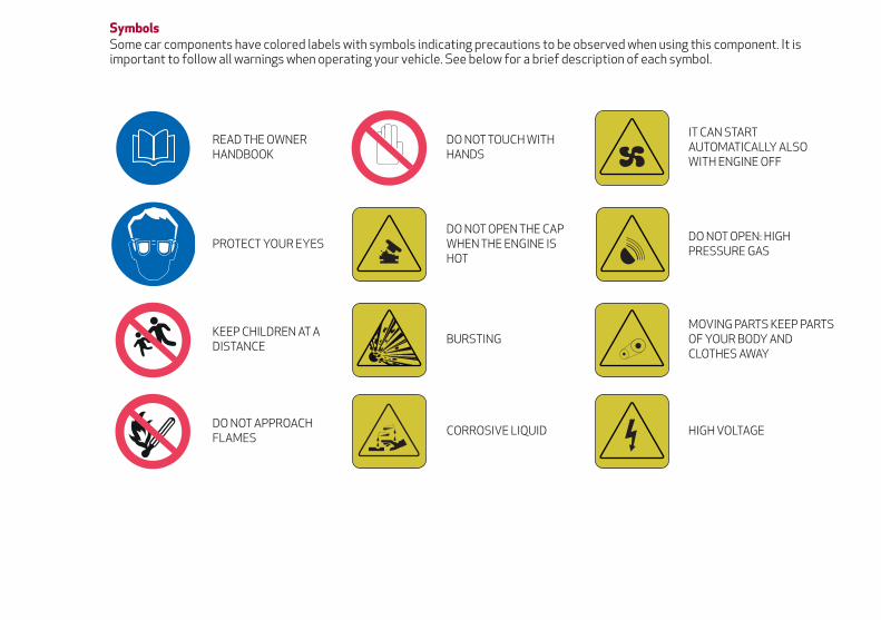
SymbolsSome car components have colored labels with symbols indicating precautions to be observed when using this component. It isimportant to follow all warnings when operating your vehicle. See below for a brief description of each symbol.
READ THE OWNERHANDBOOK
DO NOT TOUCH WITHHANDS
IT CAN STARTAUTOMATICALLY ALSOWITH ENGINE OFF
PROTECT YOUR EYESDO NOT OPEN THE CAPWHEN THE ENGINE ISHOT
DO NOT OPEN: HIGHPRESSURE GAS
KEEP CHILDREN AT ADISTANCE
BURSTINGMOVING PARTS KEEP PARTSOF YOUR BODY ANDCLOTHES AWAY
DO NOT APPROACHFLAMES
CORROSIVE LIQUID HIGH VOLTAGE

GRAPHICAL TABLE OF CONTENTS
GETTING TO KNOW YOUR VEHICLE
GETTING TO KNOW YOUR INSTRUMENT PANEL
SAFETY
STARTING AND OPERATING
IN CASE OF EMERGENCY
SERVICING AND MAINTENANCE
TECHNICAL SPECIFICATIONS
CUSTOMER ASSISTANCE
INDEX


GRAPHICAL TABLE OF CONTENTS
FRONT VIEW
03016S0001EM
Front View
1 — Headlights 4 — Doors2 — Tires And Wheels 5 — Engine Compartment3 — Power Windows 6 — Windshield
9

REAR VIEW
03026S0001EM
Rear View
1 — Tail Lights2 — Trunk Lid
10

INSTRUMENT PANEL
03036S0050EM
Instrument Panel
1 — Headlight Switch 5 — Instrument Cluster 9 — Climate Control System2 — Air Vents 6 — Steering Wheel 10 — Glove Compartment3 — Multifunction Stalk 7 — Windshield Wiper Stalk 11 — Passenger-Side Air Bag4 — Controls On Steering Wheel 8 — Information And Entertainment
System
11

VEHICLE INTERIOR
03046S0001EM
Vehicle Interior
1 — Driver Seat 4 — Hazard Warning Lights2 — Power Windows/Power Mirrors Controls 5 — Alfa DNA System3 — Gear Selector/Paddle Shifter
12
GETTING TO KNOW YOUR VEHICLE
In this section, you will find importantinformation to help you become familiarwith the features needed to operate yourvehicle, and how they function.
KEYS . . . . . . . . . . . . . . . . . . . .14IGNITION SYSTEM . . . . . . . . . . . .16ENGINE IMMOBILIZER . . . . . . . . .18SECURITY ALARM SYSTEM —IF EQUIPPED . . . . . . . . . . . . . . . .19DOORS . . . . . . . . . . . . . . . . . . .20SEATS . . . . . . . . . . . . . . . . . . . .25HEAD RESTRAINTS . . . . . . . . . . .30STEERING WHEEL . . . . . . . . . . . .31MIRRORS . . . . . . . . . . . . . . . . . .32EXTERIOR LIGHTS . . . . . . . . . . . .34INTERIOR LIGHTS . . . . . . . . . . . .36WINDSHIELD WIPERS . . . . . . . . . .39CLIMATE CONTROL . . . . . . . . . . .41POWER WINDOWS . . . . . . . . . . . .48POWER SUNROOF — IF EQUIPPED . .50HOOD . . . . . . . . . . . . . . . . . . . .51TRUNK . . . . . . . . . . . . . . . . . . .52INTERNAL EQUIPMENT . . . . . . . . .54ENVIRONMENTAL PROTECTIONSYSTEMS. . . . . . . . . . . . . . . . . .58ACTIVE AERODYNAMICS . . . . . . . .58
13

KEYSKey FobYour vehicle uses a keyless ignitionsystem. This system includes a key foband a keyless push button ignition.The Remote Keyless Entry key fob allowsyou to lock or unlock the doors and trunkor activate the Panic Alarm fromdistances. The key fob does not need tobe pointed at the vehicle to activate thesystem.
PANIC Function
The key fob contains a PANIC button.Should you ever feel threatened, pushthis button and the vehicle security alarmwill sound.To activate the PANIC function, push andhold the PANIC button for at least onesecond. When the panic alarm is active,the headlights turn on, the turn signalsflash, the horn honks intermittently, and
all interior adjustable lights turn on. Thepanic alarm will remain active for threeminutes, and can be deactivated:
By pushing the PANIC button again.
Automatically if the vehicle speedexceeds 5 mph (8 km/h).
In both cases, the panic alarm isimmediately deactivated.
Warning!
Before exiting a vehicle, always shift theautomatic transmission into PARK, applythe parking brake, turn the engine OFF,remove the key fob from the vehicle andlock your vehicle.
Never leave children alone in a vehicle, orwith access to an unlocked vehicle.
Allowing children to be in a vehicleunattended is dangerous for a number ofreasons. A child or others could be seriouslyor fatally injured. Children should be warnednot to touch the parking brake, brake pedalor the gear selector.
Do not leave the key fob in or near thevehicle, or in a location accessible tochildren. A child could operate powerwindows, other controls, or move thevehicle.
Do not leave children or animals insideparked vehicles in hot weather. Interior heatbuild-up may cause serious injury or death.
OperationDoor And Trunk Lid Unlock
Briefly pushing the unlock button on thekey fob will unlock the doors and trunklid, turn on the interior lights, and flashthe turn signals once (if activated fromthe Information and EntertainmentSystem).Push and release the unlock button on thekey fob once to unlock the driver sidefront door or twice within one second tounlock all doors and the trunk lid.The current unlock setting can bechanged through the Information andEntertainment System menu, so that thesystem unlocks:
All doors unlock on the first push ofthe key fob unlock button.
Unlock the driver door on the firstpush of the key fob unlock button.
Flashing of the turn signals uponlocking/unlocking the doors andactivation of the courtesy light uponunlocking the doors can be activated ordeactivated through the Information andEntertainment System. For furtherinformation, refer to the Information andEntertainment System Owner’s ManualSupplement.The doors can also be unlocked by usingthe emergency key, located inside thekey fob.
04016S0001EM
Key Fob
14
GE
TT
ING
TOK
NO
WY
OU
RV
EH
ICLE

Door And Trunk Lid Lock
Briefly pushing the lock button on the keyfob will lock the doors and trunk lid, turnoff the interior lights, and flash the turnsignals (if activated in the Informationand Entertainment System).If one or more doors are open, thesedoors will also lock, and this is indicatedby a rapid flashing of the turn signals. Thedoors prepare for locking, whichbecomes active from the moment theyare closed. The doors will unlock againonly if the key fob is detected inside thepassenger compartment.The doors can be locked by using theemergency key in the driver’s side doorlock.Trunk Lid Opening
Rapidly push the trunk lid key fob buttontwice to open the trunk lid. The turnsignals will flash to indicate that thetrunk lid has been opened.Remote Start
The remote start button on the key fobenables engine starting (push the buttontwice to start the engine).Car Finder
Push the lock or unlock button toremotely and temporarily turn on the turnsignals and headlights.This is useful for finding the vehicle easilyin a crowded area like a parking garage,for example.
Pushing the lock or unlock button againwill restart the lights turn on timer (if theparking lights functions were alreadyactive, it will remain active).This function is available only if the doorsare closed.
Replacing The Electronic Key FobBatteryTo replace the battery, proceed asfollows:
1. Push the sides of the key fob inwardand extract the cover pulling downwards.
2. Remove the emergency key from itshousing.
3. Remove the battery plug by rotating itcounter clockwise.
4. Remove the battery from its slot andreplace it with a new one of the sametype.
04016S0002EM
Key Fob Cover Removal
04016S0003EM
Removing Emergency Key
04016S0004EM
Removing Battery Plug
15

Proceed in reverse order to reassemblethe key.
Caution!
The battery replacement operation must bedone with care, in order not to damage theelectronic key.
Request For Additional KeysThe system can recognize up to eight keyfobs with remote control.To guarantee that the engine starts andthe vehicle operates correctly, use onlyelectronic key fobs specifically coded forthe vehicle’s electronics.If an electronic key fob is coded for avehicle, it cannot be used on any othervehicle.
Duplicating Keys
If you need a replacement key fob, go toan authorized dealer.
General InformationThe following regulatory statementapplies to all Radio Frequency (RF)devices equipped in this vehicle:This device complies with Part 15 of theFCC Rules and with Industry Canadalicense-exempt RSS standard(s).Operation is subject to the following twoconditions:
1. This device may not cause harmfulinterference, and
2. This device must accept anyinterference received, includinginterference that may cause undesiredoperation.
Note: Changes or modifications notexpressly approved by the partyresponsible for compliance could void theuser’s authority to operate theequipment.
IGNITION SYSTEMOperationTo activate the keyless ignition, the keyfob must be inside the passengercompartment.
The keyless ignition has the followingmodes:
STOP: engine off, steering locked.Some electrical devices (e.g. central doorlocking system, alarm, etc.) are stillavailable.
ON: all electrical devices are available.This state can be entered by pushing theignition button once, without pressing thebrake pedal.
AVV: engine starting. This state can beentered by pushing the ignition buttononce while pressing the brake pedal.
04016S0005EM
Battery Location
04026S0001EM
Keyless Ignition START/STOP Button
16
GE
TT
ING
TOK
NO
WY
OU
RV
EH
ICLE
Note:
With the keyless ignition in the ONposition: if 30 minutes pass with thegear selector in P (Park) and the enginestopped, the keyless ignition willautomatically reset to the STOPposition.
With the engine started, it is possibleto remove the key fob from the vehicle.The engine will remain running and theinstrument cluster will indicate theabsence of the key fob when the door isclosed.
For more information on the enginestart-up, refer to "Starting The Engine" in"Starting And Operating."
Warning!
Never use the PARK position as asubstitute for the parking brake. Alwaysapply the parking brake fully when parkedto guard against vehicle movement andpossible injury or damage.
When exiting the vehicle, always makesure the ignition is in the OFF mode, removethe key fob from the vehicle, and lock yourvehicle.
Never leave children alone in a vehicle, orwith access to an unlocked vehicle. Allowingchildren to be in a vehicle unattended isdangerous for a number of reasons. A child
or others could be seriously or fatallyinjured. Children should be warned not totouch the parking brake, brake pedal or thetransmission gear selector.
Do not leave the key fob in or near thevehicle, (or in a location accessible tochildren), and do not leave the ignition in theAVV or ON/RUN mode. A child could operatepower windows, other controls, or move thevehicle.
Be sure the parking brake is fullydisengaged before driving; failure to do socan lead to brake failure and a collision.
Always fully apply the parking brake whenleaving your vehicle, or it may roll and causedamage or injury. Also be certain to leavethe transmission in PARK. Failure to do somay allow the vehicle to roll and causedamage or injury.
Driving the vehicle with the parking brakeengaged, or repeated use of the parkingbrake to slow the vehicle may cause seriousdamage to the brake system.
Caution!
If the Brake System Warning Light remainson with the parking brake released, a brakesystem malfunction is indicated. Have thebrake system serviced by an authorizeddealer immediately.
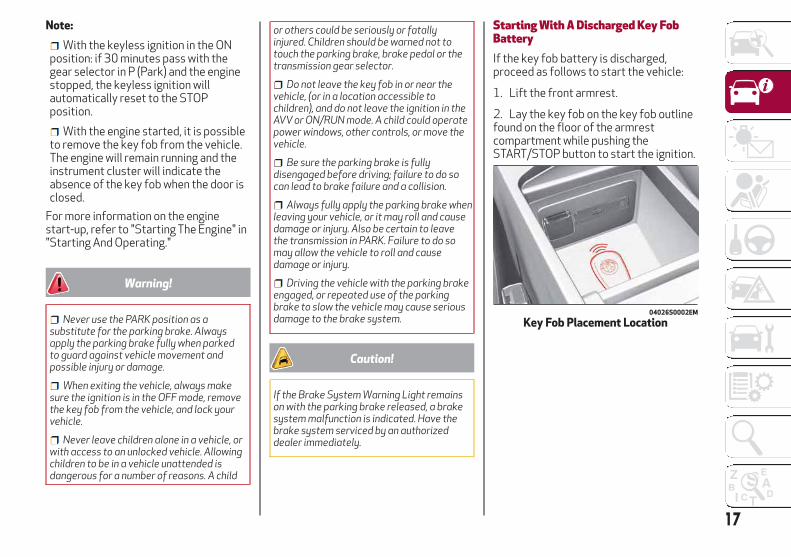
Starting With A Discharged Key FobBatteryIf the key fob battery is discharged,proceed as follows to start the vehicle:
1. Lift the front armrest.
2. Lay the key fob on the key fob outlinefound on the floor of the armrestcompartment while pushing theSTART/STOP button to start the ignition.
04026S0002EM
Key Fob Placement Location
17

General InformationThe following regulatory statementapplies to all Radio Frequency (RF)devices equipped in this vehicle:This device complies with Part 15 of theFCC Rules and with Industry Canadalicense-exempt RSS standard(s).Operation is subject to the following twoconditions:
1. This device may not cause harmfulinterference, and
2. This device must accept anyinterference received, includinginterference that may cause undesiredoperation.
Note: Changes or modifications notexpressly approved by the partyresponsible for compliance could void theuser’s authority to operate theequipment.
ENGINE IMMOBILIZEREngine Immobilizer OperationThe Engine Immobilizer system preventsunauthorized use of the vehicle bydisabling engine starting.The system does not need to be enabledor activated. Operation of theimmobilizer is automatic whether thevehicle's doors are locked or unlocked.When the ignition is set to ON, the EngineImmobilizer system identifies the codetransmitted by the key. If the code isrecognized as valid, the EngineImmobilizer system enables enginestarting.When the ignition is brought back toSTOP, the Engine Immobilizer systemdeactivates the control unit controllingthe engine, disabling engine starting.For the correct engine startingprocedures, refer to “Starting TheEngine” in “Starting And Operating.”Irregular Operation
If the key code is not recognized duringstarting, the Engine ImmobilizerFailure/Break-in Attempt icon isdisplayed on the instrument panel (referto "Warning Lights And Messages" in"Getting To Know Your InstrumentPanel"). This condition leads to the engineturning off after two seconds. In thiscase, switch the ignition to STOP andthen to ON; if it is still blocked, try withthe other keys provided. If it is still not
possible to start the engine, contact anauthorized dealer.If the Engine Immobilizer Failure/Break-in Attempt icon is displayedwhile driving, this means that the systemis running a self-diagnosis (e.g. due to avoltage drop). If the display persists,contact an authorized dealer.
Note:
Do not tamper with the EngineImmobilizer system. Any modificationsor alterations could cause the protectionfunction to be deactivated.
The Engine Immobilizer system is notcompatible with certain aftermarketremote starting systems. The use ofthese devices could cause problemswhen starting, as well as thedeactivation of the protection function.
All keys provided with the vehiclehave been programmed in accordancewith the electronics on the vehicle itself.
Each key has its own code which mustbe stored by the system's control unit.Contact an authorized dealer to havenew keys (up to eight) stored with acode.
18
GE
TT
ING
TOK
NO
WY
OU
RV
EH
ICLE

SECURITY ALARM SYSTEM —IF EQUIPPEDAlarm ActivationWhile armed, the alarm will sound in thefollowing scenarios:
Opening of doors/hood/trunk lid(perimeter protection)
Operation of ignition with a key whichis not validated
Cutting of the battery cables
Movement inside the passengercompartment (volumetric protection —if equipped)
Unexpected lifting/tilting of the vehicle(anti-lift protection — if equipped)
Activation of the alarm triggers theacoustic warning and the turn signals.Note: The alarm system is activated bythe Engine Immobilizer system, which isautomatically activated when you get outof the vehicle with the key fob and lockthe doors.
To Arm The AlarmWith the doors, hood, and trunk lid closedand the keyless ignition system placed inthe STOP position, push and release thelock button on the key fob. The alarm canalso be armed by pushing the PassiveEntry door handle button, located on theexterior door handle. For furtherinformation, refer to "Passive Entry" in"Doors.”
When the alarm is armed, the warninglights on the panels of the interior frontdoor handles will flash.
The activation of the alarm is precededby a self-diagnosis stage: if a fault isdetected, the system emits a furtheracoustic signal.If a second acoustic signal is emittedafter the alarm is already armed, waitabout four seconds and disarm the alarm
by pushing the unlock button. Verify thatthe doors, hood, and trunk lid are closedcorrectly and then rearm the system bypushing the lock button on the key fob.If the alarm emits an acoustic signal evenwhen the doors, hood, and trunk lid arecorrectly closed, a fault has occurred insystem operation. In this case, contact anauthorized dealer.
To Disarm The AlarmPush the unlock button to disarm thealarm. While disarming, the followingoperations are performed:
Two brief flashes of the turn signals (ifprogrammed)
Two brief acoustic signals (ifprogrammed)
Doors are unlocked
The alarm can also be disarmed using thePassive Entry System, by grasping one ofthe Passive Entry front door handles witha valid key fob in hand to unlock. Forfurther information refer to "PassiveEntry" in "Doors.”
04056S0003EM
Passive Entry Door Handle Button
04046S0001EM
Lock/Unlock Buttons
19

Note: The alarm does not disarm whenthe doors are unlocked by inserting theblade of the emergency key, found insidethe key fob, into the door handle lockcylinder.
Volumetric/Anti-Lift Protection —If EquippedTo ensure the correct operation of theVolumetric/Anti-Lift Protection system,completely close the side windows.To disable the function, push theVolumetric/Anti-Lift Protection buttonbefore activating the alarm.When the function is disabled, this isindicated by the light on theVolumetric/Anti-Lift Protection buttonflashing for several seconds.
Any disabling of the Volumetric/Anti-LiftProtection must be repeated each timethe instrument panel is switched off.
To Disarm The Alarm Using PassiveEntryTo completely deactivate the alarm (e.g.during a long period of vehicle inactivity),insert the blade of the emergency key,found inside the key fob, into the doorhandle lock cylinder and turn theemergency key to the right (clockwise) tolock the door(s).
DOORSLocking And Unlocking Doors From TheInsideIf all doors are closed properly, they willautomatically lock once the vehicle hasexceeded approximately 12 mph(20 km/h) (“Auto Relock” function active).Push the interior lock button on the driveror passenger side door panel trim to lockthe doors.With doors locked, push the unlockbutton on the interior trim panel tounlock the doors.Note: The key fob may not be found if itis located next to a mobile phone, lap topor other electronic device; these devicesmay block the key fob’s wireless signal.
04056S0003EM
Passive Entry Door Handle Button04046S0002EM
Volumetric/Anti-Lift Protection Button
04056S0001EM
Door Lock And Unlock Switch Panel
20
GE
TT
ING
TOK
NO
WY
OU
RV
EH
ICLE
Warning!
Do not leave children or animals insideparked vehicles in hot weather. Interior heatbuild-up may cause serious injury or death.
For personal security and safety in theevent of a collision, lock the vehicle doors asyou drive as well as when you park and leavethe vehicle.
Before exiting a vehicle, always shift theautomatic transmission into PARK, applythe parking brake, turn the engine OFF,remove the key fob from the vehicle andlock your vehicle.
Never leave children alone in a vehicle, orwith access to an unlocked vehicle.
Allowing children to be in a vehicleunattended is dangerous for a number ofreasons. A child or others could be seriouslyor fatally injured. Children should be warnednot to touch the parking brake, brake pedalor the gear selector.
Do not leave the key fob in or near thevehicle, or in a location accessible tochildren. A child could operate powerwindows, other controls, or move thevehicle.
Caution!
An unlocked vehicle is an invitation. Alwaysremove the key from the ignition and lock allof the doors when leaving the vehicleunattended.
Locking/Unlocking Doors From TheOutsideWhen locking the doors from the outsidewith the doors closed, push the lockbutton on the key fob.The door lock can be activated with alldoors locked and the trunk lid open. Whenthe lock button on the key fob is pushed,all locks are activated, including the opentrunk lid. The trunk lid will be locked whenit is closed.When unlocking the doors from theoutside, push the unlock button on thekey fob.Locking/Unlocking Doors From TheOutside In An Emergency
If the battery is discharged or the key fobis inoperable, you can lock or unlock thedoors from the outside by inserting theblade of the emergency key, found insidethe key fob, into the door handle lockcylinder and turn the emergency key asfollows.
Lock — Turn the emergency key to theright (clockwise)
Unlock — Turn the emergency key tothe left (counter clockwise)
Passive Entry — If EquippedThe Passive Entry system can identifythe presence of a key fob near the doorsand trunk lid.The system enables the doors and trunklid to be locked or unlocked withoutpushing any button on the key fob.The key fob is detected only after thesystem recognizes the presence of ahand on one of the front door handles. Ifthe detected key fob is valid, the doorsand the trunk lid are unlocked (refer tothe Information and EntertainmentSystem Owner’s Manual Supplement forPassive Entry Settings).Note: The key fob may not be able to bedetected by the vehicle keyless-gosystem if it is located next to a mobilephone, laptop or other electronic device;these devices may block the key fob’swireless signal and prevent thekeyless-go system from starting thevehicle.Grasping the handle of the driver's doorunlocks the driver's side door, or all doorsdepending on the mode set using theInformation and Entertainment System(refer to the Information andEntertainment System Owner’s ManualSupplement for Passive Entry Settings).Note: If wearing gloves, or if it has rainedand the door handle is wet, the activation
21

sensitivity of the Passive Entry functionmay be reduced, resulting in a longerreaction time.Door Locking
To lock the doors, proceed as follows:
1. Make sure that you have the key foband are close to the driver’s orpassenger’s side door handle.
2. Push the Passive Entry door handlebutton or the Passive Entry trunk lidbutton, which is located next to theexterior trunk lid release button. This willlock all doors and the trunk lid. Doorlocking will activate the alarm as well.
Note: After pushing the Passive Entrydoor handle button, you must wait twoseconds before the doors can beunlocked again using the passive entrydoor handle button. This feature makes itpossible to check whether the vehicle hasbeen locked correctly by pulling the doorhandle within two seconds. The doors willnot be unlocked again.The vehicle doors and trunk lid can belocked by pushing the lock button on thekey fob or on the interior door lock.Driver Side Door Emergency Opening
If the key fob does not work, e.g. becauseits battery is discharged or the vehiclebattery is discharged, the emergency keycan be used to unlock the driver sidedoor.To remove the emergency key from thekey fob, proceed as follows:
1. Push the sides of the key fob inwardand extract the cover pulling downwards.
2. Remove the emergency key from thekey fob housing.
3. Insert the emergency key in the driverside door lock cylinder and turn it to theleft (counter clockwise) to unlock thedoor.
Note:
The emergency key blade is notdirectional and can be insertedindifferently into the lock.
04056S0003EM
Passive Entry Door Handle Button
04056S0006EM
Passive Entry Trunk Lid Button
04016S0002EM
Emergency Key Release Buttons
04016S0003EM
Emergency Key
22
GE
TT
ING
TOK
NO
WY
OU
RV
EH
ICLE

To avoid leaving the key fob insidethe vehicle accidentally, the PassiveEntry function features an automaticdoor unlocking function.
If one of the vehicle doors is open andthe "door locking" button on the frontdoor handles or lock button in theinterior door lock switch panel is pushed,a check of the inside and outside of thevehicle for the presence of the key fob ismade once all the open doors are closed.
While pulling the handle, do not push thedoor lock/unlock button on the handle.
If the key fob is detected inside thevehicle, the Passive Entry functionautomatically unlocks all the vehicledoors and flashes the turn signals.If one or more key fobs are inside thepassenger compartment, the lock buttonon the key fob inside the passengercompartment is temporarily disabled.The vehicle will not unlock the doors if anunauthorized key fob has been detectedclose to the outside of the vehicle.If the Passive Entry function is disabledusing the Information and EntertainmentSystem, the protections to avoidaccidentally leaving the key fob insidethe vehicle are deactivated.
Trunk Lid Access
Approaching the trunk lid with a valid keyfob, push the opening button to accessthe trunk lid.
Note:
If the key fob is inadvertentlyforgotten inside of the trunk, and anattempt is made to close it from outside,the trunk lid will not lock. With the doorslocked, the trunk lid unlocked, and thekey fob detected inside the vehicle, thetrunk lid will unlock again and the lightsflash twice.
Before driving, make sure the trunklid is closed correctly.
Trunk Lid Lock
The trunk lid of the vehicle may still belocked by pushing the lock button on thekey fob, pushing the door lock button onthe door handles, or pushing the lockbutton on the interior door panel of thevehicle.
04056S0003EM
Passive Entry Door Handle Button
04056S0001EM
Interior Lock Switch Panel
04056S0004EM
Do NOT Grab The Door Handle WhenLocking
04056S0005EM
Exterior Trunk Lid Release Button
23

On vehicles equipped with Passive Entry,the trunk lid and the doors can be lockedby pushing the button located near theopening button of the trunk lid.
System Activation/Deactivation
The Passive entry system can beactivated or deactivated using theInformation and Entertainment System.
General InformationThe following regulatory statementapplies to all radio frequency (RF)devices equipped in this vehicle:This device complies with Part 15 of theFCC Rules and with Industry Canadalicense-exempt RSS standard(s).Operation is subject to the following twoconditions:
1. This device may not cause harmfulinterference, and
2. This device must accept anyinterference received, includinginterference that may cause undesiredoperation.
Note: Changes or modifications notexpressly approved by the partyresponsible for compliance could void theuser’s authority to operate theequipment.
Power Lock — If EquippedThe Power Lock is a safety device thatprevents the operation of the interiordoor handles and the door locking andunlocking buttons. The Power Lock alsoprevent opening of the doors from insidethe passenger compartment.It is recommended to lock the vehicledoors each time the vehicle is parked.Activating The Power Lock
The Power Lock is enabled on all thedoors by quickly pushing the lock buttonon the key fob twice.The turn signals will flash to let you knowthat the Power Lock is active.If one or more of the doors are not closedcorrectly, the Power Lock will notactivate, preventing a person fromgetting stuck inside the passengercompartment by entering the vehicle, andthen closing, the open door.Deactivating The Power Lock
The Power Lock disengagesautomatically:
When the doors are unlocked, pushingthe unlock button on the key fob.
When the keyless ignition is placed inthe ON position.
Child Safety LocksTo provide a safer environment for smallchildren riding in the rear seats, the reardoors are equipped with Child-ProtectionDoor Lock system.This device can be engaged only with thedoors open.
Lock position: device locked (dooropened from exterior only)
Unlock position: device unlocked (doormay be opened from the inside)
The Child Safety Locks remain lockedeven if the doors are unlocked.Note: The rear doors cannot be openedfrom the inside when the Child SafetyLock is engaged.
04056S0006EM
Passive Entry Trunk Lid Button
04056S0007EM
Child Safety Lock Positions
24
GE
TT
ING
TOK
NO
WY
OU
RV
EH
ICLE

Unlocking The Doors With A DischargedBatteryProceed as follows to unlock the doors ifthe vehicle battery is discharged.Rear Doors And Passenger Door
1. With the doors unlocked insert theemergency key from the key fob or a flatbladed screwdriver into the door lockmanual release lock cylinder.
2. Turn the manual release lock cylinderclockwise for the right door locks orcounterclockwise for the left door locks.
3. Remove the key/screwdriver from themanual release lock.
Proceed as follows to realign the doorlock device (only when the battery chargehas been restored):
Push the lock button on the electronickey
Push the unlock button on the doorpanel
Unlock driver’s door lock with theemergency key
Operate the internal door handle
Note: For the rear doors, if the ChildSafety Locks are engaged, and thepreviously described locking procedure iscarried out, operating the internal handlewill not open the door. Instead, it will onlyrealign the lock release device. To openthe door, the outside handle must beused. The door central locking/unlockingbuttons are not deactivated when theemergency lock is engaged.
SEATSThe front seats can be adjusted to ensuremaximum comfort for the occupants.When adjusting the driver’s seat, keepthe shoulders resting firmly against thebackrest, and the wrists within reach ofthe top of the steering wheel. The drivermust also be able to fully press the brakepedal.
Warning!
It is dangerous to ride in a cargo area,inside or outside of a vehicle. In a collision,people riding in these areas are more likelyto be seriously injured or killed.
Do not allow people to ride in any area ofyour vehicle that is not equipped with seatsand seat belts. In a collision, people riding inthese areas are more likely to be seriouslyinjured or killed.
Be sure everyone in your vehicle is in aseat and using a seat belt properly.
Sparco Racing Seats — If EquippedForward/Rearward Adjustment
The adjustment lever is at the front of theseat, near the floor. Pull the bar upwardto move the seat forward or rearward.Release the bar once the seat is in theposition desired. Using body pressure,move forward and rearward on the seatto be sure that the seat adjusters havelatched.
04056S0008EM
Door Lock Manual Release LockCylinder
25
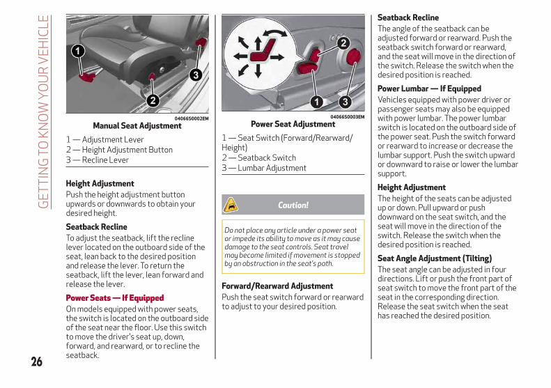
Height Adjustment
Push the height adjustment buttonupwards or downwards to obtain yourdesired height.
Seatback Recline
To adjust the seatback, lift the reclinelever located on the outboard side of theseat, lean back to the desired positionand release the lever. To return theseatback, lift the lever, lean forward andrelease the lever.
Power Seats — If EquippedOn models equipped with power seats,the switch is located on the outboard sideof the seat near the floor. Use this switchto move the driver's seat up, down,forward, and rearward, or to recline theseatback.
Caution!
Do not place any article under a power seator impede its ability to move as it may causedamage to the seat controls. Seat travelmay become limited if movement is stoppedby an obstruction in the seat's path.
Forward/Rearward Adjustment
Push the seat switch forward or rearwardto adjust to your desired position.
Seatback Recline
The angle of the seatback can beadjusted forward or rearward. Push theseatback switch forward or rearward,and the seat will move in the direction ofthe switch. Release the switch when thedesired position is reached.
Power Lumbar — If Equipped
Vehicles equipped with power driver orpassenger seats may also be equippedwith power lumbar. The power lumbarswitch is located on the outboard side ofthe power seat. Push the switch forwardor rearward to increase or decrease thelumbar support. Push the switch upwardor downward to raise or lower the lumbarsupport.
Height Adjustment
The height of the seats can be adjustedup or down. Pull upward or pushdownward on the seat switch, and theseat will move in the direction of theswitch. Release the switch when thedesired position is reached.
Seat Angle Adjustment (Tilting)
The seat angle can be adjusted in fourdirections. Lift or push the front part ofseat switch to move the front part of theseat in the corresponding direction.Release the seat switch when the seathas reached the desired position.
04066S0002EM
Manual Seat Adjustment
1 — Adjustment Lever2 — Height Adjustment Button3 — Recline Lever
04066S0003EM
Power Seat Adjustment
1 — Seat Switch (Forward/Rearward/Height)2 — Seatback Switch3 — Lumbar Adjustment
26
GE
TT
ING
TOK
NO
WY
OU
RV
EH
ICLE

Power Bolster Adjustment
Push the power bolster adjustmentbuttons to regulate the width of thebackrest through the lateral padding.
Driver Memory Seat
The driver memory seat buttons canstore and recall three different driver’sseat positions as well as outside powermirror positions. Storing and recalling ispossible with the ignition in the ON orSTOP positions and the driver’s side doorclosed, or for three minutes after havingopened the driver's side door. Theperformed position memory is confirmedby a beep. To set a memory profile, firstadjust your seat (and power mirrorposition if desired) with the variouscontrols until you are in the desiredposition. Then, push the specific buttonyou want to assign the set position to for
1.5 seconds. When a new seat position ismemorized, the previously memorizedposition on the same button isautomatically overwritten. Recalling amemorized position is also possible forapproximately three minutes after thedoors are opened and approximately oneminute after the engine is stopped. Torecall a memorized position, push therelevant button briefly.
Warning!
Adjusting a seat while driving may bedangerous. Moving a seat while drivingcould result in loss of control which couldcause a collision and serious injury or death.
Seats should be adjusted beforefastening the seat belts and while thevehicle is parked. Serious injury or deathcould result from a poorly adjusted seatbelt.
Do not ride with the seatback reclined sothat the shoulder belt is no longer restingagainst your chest. In a collision you couldslide under the seat belt, which could resultin serious injury or death.
Heated Seats — If EquippedWith the engine in the ON position, pushthe driver or passenger heated seatbutton located on the instrumentpanel.
You can select three heating levels:
Minimum — one orange indicatorilluminated on the buttons
Average — two orange indicatorsilluminated on the buttons
Maximum — three orange indicatorsilluminated on the buttons
After selecting a heating level, heat willbe felt within a few minutes.A quick push of the heated seat buttonwill select the heat levels in order oflowest to highest. Or, holding the switchdown from either “off” or the minimumlevel for 1–2 seconds will automaticallyselect the maximum heat level.When the heated seat function is notactive, pushing and holding the desiredheated seat button for 1–2 seconds willactivate the “fast maximum heating”function. The heater produces a boostedheat level for the first few minutes ofoperation. After this, the heat
04066S0015EM
Seatback Width Adjustment
4 — Power Adjustable Bolster Buttons5 — Driver Memory Seat Buttons
04066S0004EM
Heated Seat Buttons
27

automatically lowers to reach the normaltemperature level for the “maximum”setting.The “minimum” setting is automaticallydeactivated once a certain period of timehas elapsed. This varies on acase-by-case basis, in accordance withthe specific operating conditions.To lower the heat level, each quick pushof the switch will decrease by one leveluntil it is off. Holding the switch down atany of the three levels for 1-2 secondswill deactivate the heated seat.Note: To preserve the battery charge,this function cannot be activated whenthe engine is off.
Warning!
Persons who are unable to feel pain to theskin because of advanced age, chronicillness, diabetes, spinal cord injury,medication, alcohol use, exhaustion or otherphysical condition must exercise care whenusing the seat heater. It may cause burnseven at low temperatures, especially if usedfor long periods of time
Do not place anything on the seat orseatback that insulates against heat, suchas a blanket or cushion. This may cause theseat heater to overheat. Sitting in a seatthat has been overheated could causeserious burns due to the increased surfacetemperature of the seat.
Rear SeatsThe rear seats allow for threepassengers.
Note: Middle Seat: The rear seat isdesigned as a 4+1 seat vehicle. Themiddle seat is of limited use. It isrecommended that this seat only be usedby a person who can use the backrest as asubstitute for the head restraint.
The seats and the seatbelts areconsidered components of the vehicle’sOccupant Restraint System.Note: Refer to the "Seat Belt Systems"in "Safety" for further information.
Split Folding Rear Seat — If EquippedThe rear seatbacks can be foldedforward to provide an additional storagearea.
Partial Extension Of The LuggageCompartment (1/3 Or 2/3)
Extending the right side of the trunkallows you to carry two passengers onthe left part of the rear seat, whileextending the left side allows you tocarry one passenger.Proceed as follows:
1. Completely lower the rear seat headrestraints.
2. Place the seatbelt so that it doesn'timpede the movement of the backrestwhile tilting it.
3. From inside the luggagecompartment, operate lever 1 to tilt theleft part or lever 2 to tilt the right part ofthe backrest: it will automatically tiltforward. If necessary, assist the backrestduring the initial stage of tilting.
04066S0005EM
Rear Seat
04066S0005EM
Rear Seat
28
GE
TT
ING
TOK
NO
WY
OU
RV
EH
ICLE

Full Expansion Of The Trunk
Tilting the rear seat forward completelyallows maximum loading volume.Proceed as follows:
1. Completely lower the rear seat headrestraints.
2. Place the seatbelts so that they don'timpede the movement of the backrestwhile tilting it.
3. From inside the luggagecompartment, use levers 1 and 2 to folddown the backrests; these will fold downforwards automatically. If necessary,accompany the backrests during theinitial stage of tilting.
Repositioning The Backrests
Move the seatbelts to the side, makingsure that they are correctly extended andnot twisted, and that they are nottrapped behind the backrests of theseats. Then, lift the backrests, pushingthem back until you hear the locking clickon both attachment mechanisms.
Warning!
Be certain that the seatback is securelylocked into position. If the seatback is notsecurely locked into position the seat will notprovide the proper stability for child seatsand/or passengers. An improperly latchedseat could cause serious injury.
Center Backrest Section Tilting
Before tilting the backrest, make surethat the rear center seatbelt is notfastened and that there aren't anyobjects in the middle part of the cushion(if there are any, remove them).Using the release strap, release thecenter part of the backrest from itshousing and tilt it using the headrestraint.
Center Backrest Section Repositioning
Using the head restraint, lift the centerportion upwards, accompanying it duringits movement, and lightly push to makesure that it is properly attached. Makesure that the armrest is properlyattached by attempting to move it. If it isnot attached, repeat the operation.
04066S0007EM
Seat Release Levers
1 — Left Side Seat Release Lever2 — Right Side Seat Release Lever
04066S0008EM
Center Backrest Section Tilting
29
HEAD RESTRAINTSHead restraints are designed to reducethe risk of injury by restricting headmovement in the event of a rear impact.Head restraints should be adjusted sothat the top of the head restraint islocated above the top of your ear.
Warning!
A loose head restraint thrown forward ina collision or hard stop could cause seriousinjury or death to occupants of the vehicle.Always securely stow removed headrestraints in a location outside the occupantcompartment.
ALL the head restraints MUST bereinstalled in the vehicle to properly protectthe occupants. Follow the re-installationinstructions above prior to operating thevehicle or occupying a seat.
Do not place items over the top of theReactive Head Restraint, such as coats,seat covers or portable DVD players. Theseitems may interfere with the operation ofthe Reactive Head Restraint in the event ofa collision and could result in serious injuryor death.
Racing Seat Head RestraintsYour vehicle may be equipped withnon-adjustable head restraints on thedriver's and passenger's seatbacks.The non-adjustable head restraintsconsist of a trimmed foam covering over
the upper structure of the seatbacks andare intended to help protect you and thepassenger from neck injury.Adjust the seatbacks to their upright,on-road positions so that the headrestraint is positioned as close aspossible to the back of your head.
Front Head Restraints (Adjustments)— If EquippedThe front head restraints may beheight-adjustable. To adjust them,operate as follows:
Upward adjustment: Raise the headrestraint until it clicks into place.
Downward adjustment: Push theadjustment button and push downwardon the head restraint to lower.
Warning!
All occupants, including the driver, shouldnot operate a vehicle or sit in a vehicle’s seatuntil the head restraints are placed in theirproper positions in order to minimize therisk of neck injury in the event of a crash.
Head restraints should never be adjustedwhile the vehicle is in motion. Driving avehicle with the head restraints improperlyadjusted or removed could cause seriousinjury or death in the event of a collision.
Note: To allow maximum visibility for thedriver, if the head restraints are not used,lower the head restraints to the fullydown position.
Rear Head Restraints (Adjustments)
Warning!
All occupants, including the driver, shouldnot operate a vehicle or sit in a vehicle’s seatuntil the head restraints are placed in theirproper positions in order to minimize therisk of neck injury in the event of a crash.
Head restraints should never be adjustedwhile the vehicle is in motion. Driving avehicle with the head restraints improperlyadjusted or removed could cause seriousinjury or death in the event of a collision.
The height of the outboard headrestraints can be adjusted. The headrestraint of the center seat, if equipped,cannot be adjusted, only removed.For upward adjustment, pull up on thehead restraint until it clicks into place.For downward adjustment, push in theadjustment button and lower the headrestraint while holding the button to thedesired height.
30
GE
TT
ING
TOK
NO
WY
OU
RV
EH
ICLE

Note: To allow maximum visibility for thedriver, if the head restraints are not inuse, lower the head restraints to the fullydown position.
Head Restraints (Removal)To remove the head restraints, proceedas follows:
1. Raise the head restraints to theirmaximum height.
2. Push the adjustment button and therelease button at the side of the twosupports.
3. Remove the head restraints by pullingthem upwards.
To reinstall the head restraints, proceedas follows:
1. Hold down both the adjustmentbutton and release button while placingthe head restraint post into the holes.
2. Then, reposition the head restraint tothe appropriate height for thepassengers.
Warning!
A loose head restraint thrown forward ina collision or hard stop could cause seriousinjury or death to occupants of the vehicle.Always securely stow removed headrestraints in a location outside the occupantcompartment.
ALL the head restraints MUST bereinstalled in the vehicle to properly protectthe occupants. Follow the re-installationinstructions above prior to operating thevehicle or occupying a seat.
STEERING WHEELAdjustmentsThis feature allows you to tilt thesteering column upward or downward. Italso allows you to lengthen or shorten thesteering column. The tilt/telescopinglever is located below the steering wheelat the end of the steering column.
04076S0002EM
Rear Head Restraint
1 — Adjustment Button2 — Release Button
04086S0001EM
Steering Wheel Adjustment
1 — Tilt/Telescoping Control HandleA — OpenB — Closed
31

Warning!
Do not adjust the steering column whiledriving. Adjusting the steering column whiledriving or driving with the steering columnunlocked, could cause the driver to losecontrol of the vehicle. Failure to follow thiswarning may result in serious injury or death.
To Adjust The Position:
1. Pull the Tilt/Telescoping ControlHandle down to the open position.
2. Adjust the steering wheel to thedesired position.
3. Lock the desired position by pushingthe Tilt/Telescoping Control Handle tothe closed position.
Warning!
It is absolutely forbidden to carry out anyafter-market operation involving steeringsystem or steering column modifications(e.g. installation of anti-theft device) thatcould adversely affect performance. Doingso could void the New Vehicle LimitedWarrant, cause SERIOUS SAFETYPROBLEMS INCLUDING INJURY, and alsoresult in the vehicle not meetingtype-approval requirements.
Heated Steering Wheel — If EquippedWhile the engine is running, push theheated steering wheel button on theinstrument panel.
When the function is enabled, theindicator on the button will illuminate.
Warning!
Persons who are unable to feel pain to theskin because of advanced age, chronicillness, diabetes, spinal cord injury,medication, alcohol use, exhaustion, or otherphysical conditions must exercise care whenusing the steering wheel heater. It maycause burns even at low temperatures,especially if used for long periods.
Do not place anything on the steeringwheel that insulates against heat, such as ablanket or steering wheel covers of any typeand material. This may cause the steeringwheel heater to overheat.
MIRRORSElectrochromic MirrorThis mirror automatically adjusts forheadlight glare from vehicles behind you.The electrochromic mirror has a powerbutton to activate/deactivate theautomatic dimming/anti-glaring function.
When the vehicle is in REVERSE, theautomatic dimming feature isdeactivated.
Outside Power MirrorsPower Adjustment
The power mirrors can be adjusted withthe ignition ON.Select the desired mirror using the powermirror control.
04086S0002EM
Heated Steering Wheel Button
04106S0002EM
Electrochromic Mirror Power Button
32
GE
TT
ING
TOK
NO
WY
OU
RV
EH
ICLE

To adjust the selected mirror, push theknob in the direction desired.Note: Once adjustment is complete,rotate the knob to the neutral position toprevent accidental movements.
Power Folding
With the power mirror control knob in theneutral position, move it to the powerfolding position. Move the knob again toreturn the mirrors to the driving position.If the power mirror control knob is movedagain during door mirror folding (fromclosed to open position and vice versa),the movement direction is reversed.
Automatic Activation
Activating the central door lockingsystem from outside the vehicleautomatically folds the mirrors. Themirrors return to the driving positionwhen the ignition is cycled to the ONposition.If the door mirrors were folded using thepower mirror control knob, they can onlybe returned to the driving position byrotating the knob again.Note: The power folding operation canbe enabled only when the vehicle speed islower than 31 mph (50 km/h). They canonly be manually controlled up to thatspeed.
Automatic Dimming Mirrors —If Equipped
Like the electrochromic mirror, anautomatic dimming feature is alsoavailable on the outside rear view mirrorsto prevent glare. The automatic dimmingbutton is the same for all rear viewmirrors.
Warning!
Vehicles and other objects seen in an outsideconvex mirror will look smaller and fartheraway than they really are. Relying too muchon side convex mirrors could cause you tocollide with another vehicle or other object.Use your inside mirror when judging the sizeor distance of a vehicle seen in a side convexmirror.
Heated MirrorsPush the rear defrost button in theclimate controls to activate the heatedmirrors.
04106S0004EM
Power Mirror Control
1 — Power Mirror Control KnobA — LeftB — RightC — Power Folding PositionD — Neutral
33
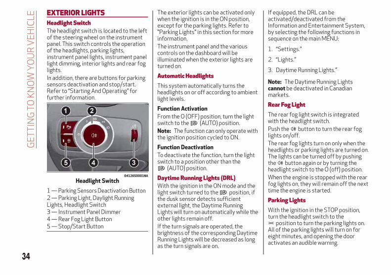
EXTERIOR LIGHTSHeadlight SwitchThe headlight switch is located to the leftof the steering wheel on the instrumentpanel. This switch controls the operationof the headlights, parking lights,instrument panel lights, instrument panellight dimming, interior lights and rear foglights.In addition, there are buttons for parkingsensors deactivation and stop/start.Refer to “Starting And Operating” forfurther information.
The exterior lights can be activated onlywhen the ignition is in the ON position,except for the parking lights. Refer to"Parking Lights" in this section for moreinformation.The instrument panel and the variouscontrols on the dashboard will beilluminated when the exterior lights areturned on.
Automatic HeadlightsThis system automatically turns theheadlights on or off according to ambientlight levels.
Function Activation
From the O (OFF) position, turn the lightswitch to the (AUTO) position.Note: The function can only operate withthe ignition position cycled to ON.
Function Deactivation
To deactivate the function, turn the lightswitch to a position other than the
(AUTO) position.
Daytime Running Lights (DRL)With the ignition in the ON mode and thelight switch turned to the position, ifthe dusk sensor detects sufficientexternal light, the Daytime RunningLights will turn on automatically while theother lights remain off.If the turn signals are operated, thebrightness of the corresponding DaytimeRunning Lights will be decreased as longas the turn signals are on.
If equipped, the DRL can beactivated/deactivated from theInformation and Entertainment System,by selecting the following functions insequence on the main MENU:
1. “Settings.”
2. “Lights.”
3. Daytime Running Lights.”
Note: The Daytime Running Lightscannot be deactivated in Canadianmarkets.
Rear Fog LightThe rear fog light switch is integratedwith the headlight switch.Push the button to turn the rear foglights on/off.The rear fog lights turn on only when theheadlights or parking lights are turned on.The lights can be turned off by pushingthe button again or by turning theheadlight switch to the O (off) position.When the engine is stopped with the rearfog lights on, they will remain off the nexttime the engine is started.
Parking LightsWith the ignition in the STOP position,turn the headlight switch to the
position to turn the parking lights on.All of the parking lights will turn on foreight minutes, and opening the dooractivates an audible warning.
04126S0001NA
Headlight Switch
1 — Parking Sensors Deactivation Button2 — Parking Light, Daylight RunningLights, Headlight Switch3 — Instrument Panel Dimmer4 — Rear Fog Light Button5 — Stop/Start Button
34
GE
TT
ING
TOK
NO
WY
OU
RV
EH
ICLE

To leave only the lights on one side(right/left) illuminated, you must movethe multifunction lever (located on theleft side of the steering wheel) to the sidethat you want to remain on. With theparking lights on, the warning light onthe instrument panel will come on.Note: Placing the ignition to ON turns offthe parking lights, which were onlyilluminated on one side.
Headlight Off DelayThe “Headlight Off Delay” function delaysthe turning off of the headlights after thevehicle has been stopped.The function can be activated from theInformation and Entertainment Systemby selecting the following functions insequence on the main menu:
1. “Settings.”
2. “Lights.”
3. “Headlight Off Delay.”
The side lights and the headlights stay onfor a time that can be set between 30,60, and 90 seconds.
Function Activation
With the headlights on, cycle the ignitionto STOP mode, the timer will then start.Note: To activate this function, theheadlights must be deactivated withintwo minutes after the ignition has beencycled to STOP.
Function Deactivation
This function is deactivated by turning onthe headlights, the side lights, or bycycling the ignition to ON.
High Beam HeadlightsTo activate the fixed high beamheadlights, push the multifunction lever,located on the left side of the steeringwheel, towards the instrument panel. Theheadlight switch must be turned to the
(AUTO) or (ON) position.With high beam headlights on, the
High Beam Indicator on theinstrument panel will illuminate.
The high beam headlights are turned offby pulling the lever to its original position.The warning light/icon will turn off inthe instrument panel when the headlightsare turned off.
Flashing The Headlights
Pulling the multifunction lever toward thesteering wheel will activate the highbeam headlights manually. The lights willremain on as long as the lever is held.Once the lever is released, the lights willresume the previous position.
Automatic High Beam Headlights —If Equipped
The Automatic High Beam Headlightssystem provides increased forwardlighting at night by automating high beamcontrol through the use of a digitalcamera mounted on the windshield. Thiscamera detects vehicle specific light andautomatically switches from high beamsto low beams until the approachingvehicle is out of view.This function is enabled with theInformation and Entertainment System,and can only be activated with the lightswitch turned to (AUTO).If the high beam headlights are on, theblue icon/warning light will illuminatein the instrument panel.When the speed is higher than 37 mph(60 km/h) and the function is active, thelights will turn off if the multifunctionlever is pushed again.When the speed is lower than 15 mph(25 km/h) and the function is active, thefunction switches the high beamheadlights off.If the high beam headlights are operatedquickly again (pushing the multifunction
04126S0020EM
Multifunction Lever
35

lever towards the instrument panel), thewarning light/icon will illuminate in theinstrument panel, and the main beamheadlights will turn on constantly untilthe speed exceeds 37 mph (60 km/h).When the speed of 37 mph (60 km/h) isexceeded again, the automaticfunctioning is reactivated.If the multifunction lever is pushed againwith the Automatic High BeamHeadlights activated, the Automatic HighBeam Headlights function deactivates.To deactivate the automatic headlightfunction, rotate the headlight switch tothe position.Note: If the system recognizes heavytraffic areas, the automatic functionsremain disabled independently of thevehicle’s speed.
Turn SignalsTo activate the turn signals function,move the multifunction lever, located onthe left side of the steering wheel, up ordown until it reaches the detent. Movingthe lever upward flashes the right turnsignal and moving the lever downwardwill flash the left turn signal.The or turn signal will blink on theinstrument panel.The turn signals turn off automaticallywhen the vehicle is brought back onto astraight course.
“Lane Change” Function
Tap the lever up or down once, withoutmoving beyond the detent, and the turnsignal (right or left) will flash five times.Then, the turn signal (right or left) willautomatically turn off.To turn off the flashing before the end ofthe cycle, move the lever in the oppositedirection until the first click (about halfway).
Static Bending Light Function (SBL) —If EquippedThe SBL function utilizes Light EmittingDiodes (LEDs) in order to betterilluminate the street and increase thelight angle while turning. This function isenabled by rotating the light switch toposition or (AUTO). The SBL LEDsactivate when the speed is below 25 mph(40 km/h).This function can be activated/deactivated on the Information andEntertainment System by selecting thefollowing functions in sequence on themain menu:
1. “Settings.”
2. “Lights.”
3. “Cornering Lights.”
INTERIOR LIGHTSFront Map Reading LightsThe front map/reading and overheadlights are mounted in the overheadconsole. Each light can be turned on bypushing the corresponding switch on theconsole. These switches are backlit fornight time visibility. To turn the lights off,push the switch a second time.
Note: Before getting out of the vehicle,ensure that the overhead lights are off.This will prevent the battery level from
04136S0001EM
Overhead Console
1 — Driver’s Reading/Map Light Switch2 — Rear Overhead Lights Switch3 — Overhead Lights Switch4 — Front Map Reading Lights Switch5 — Passenger’s Reading/Map LightSwitch6 — Passenger’s Reading/Map Light7 — Center Reading/Map Light8 — Driver’s Reading/Map Light
36
GE
TT
ING
TOK
NO
WY
OU
RV
EH
ICLE

being drained once the doors are closed.If a light is left on accidently, theoverhead lights turn off automaticallyapproximately 15 minutes after theengine has been turned OFF.
Overhead Light Timing — If Equipped
On certain models, to assist getting inand out of the vehicle at night or inpoorly-lit areas, two timed modes havebeen provided.Timing While Getting Into The Vehicle— The overhead lights turn on accordingto the following modes:
Will illuminate for a few seconds whenthe doors are unlocked.
Will illuminate for approximately threeminutes when one of the doors is opened.
Will illuminate for a few seconds whenthe doors are locked.
Timing is interrupted when the ignition iscycled to ON.Three Modes Are Provided ForSwitching Off:
When all doors are closed afterentering the vehicle, the three-minutetimer will stop and a seconds timer willstart for the interior lights. This timingwill stop when the ignition is cycled toON.
When doors are locked (either with keyfob or with key inserted on driver sidedoor), the overhead light turns off.
The interior lights will turn off after15 minutes to preserve the battery.
Timing While Getting Out Of TheVehicle — After cycling the ignition toSTOP, the overhead lights will turn on asfollows:
For a few seconds after the enginestops.
For approximately three minutes whenone of the doors is opened.
For a few seconds when the last dooris closed.
The timing stops automatically when thedoors are locked.
Vanity Mirror Lights — If Equipped
On the driver and passenger sun visor,there is a light which illuminates the sunvisor mirror when folded down.
The courtesy light turns on automaticallyby lifting the cover.
Glove Compartment LightThis light turns on automatically when theglove compartment is opened and turnsoff when it is closed.The light turns on and off regardless ofthe ignition status.
Interior Ambient LightingThe brightness of the interior passengercompartment lights can be adjusted viathe Information and EntertainmentSystem.To access the adjustment function, on themain menu select the following items insequence:
1. "Settings."
2. "Interior Ambient Lighting."
3. "Lights."
04136S0002EM
Sun Visor Mirror
1 — Sun Visor Mirror Cover
04136S0003EM
Glove Compartment Light
37
The lights can be adjusted to sevendifferent levels of brightness.
Door LightThis vehicle is equipped with doorcourtesy lamps that illuminate the entryway for the driver or passenger when thedoor is opened, and turns off when it isclosed.The light turns on and off regardless ofthe ignition status.
On vehicles equipped with a "PassiveEntry" system, another light can be foundunder each exterior door handle.
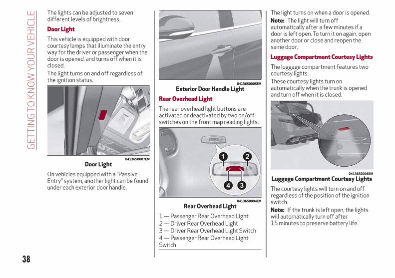
Rear Overhead LightThe rear overhead light buttons areactivated or deactivated by two on/offswitches on the front map reading lights.
The light turns on when a door is opened.Note: The light will turn offautomatically after a few minutes if adoor is left open. To turn it on again, openanother door or close and reopen thesame door.
Luggage Compartment Courtesy LightsThe luggage compartment features twocourtesy lights.These courtesy lights turn onautomatically when the trunk is openedand turn off when it is closed.
The courtesy lights will turn on and offregardless of the position of the ignitionswitch.Note: If the trunk is left open, the lightswill automatically turn off after15 minutes to preserve battery life.
04136S0007EM
Door Light
04136S0005EM
Exterior Door Handle Light
04136S0004EM
Rear Overhead Light
1 — Passenger Rear Overhead Light2 — Driver Rear Overhead Light3 — Driver Rear Overhead Light Switch4 — Passenger Rear Overhead LightSwitch
04136S0006EM
Luggage Compartment Courtesy Lights
38
GE
TT
ING
TOK
NO
WY
OU
RV
EH
ICLE
Instrument Panel Dimmer ControlWith the daytime running lights orheadlights on, rotate the dimmer controlupward to increase the instrument panelbrightness and the control button icons.Rotate the dimmer control downward todecrease brightness.
WINDSHIELD WIPERSWindshield Wiper StalkThe windshield wiper stalk is located onthe right side of the steering wheel.The windshield wipers will only operatewith the ignition cycled to ON.
Caution!
Turn the windshield wipers off whendriving through an automatic car wash.Damage to the windshield wipers may resultif the wiper control is left in any positionother than off.
In cold weather, always turn off the wiperswitch and allow the wipers to return to the“Park” position before turning off theengine. If the wiper switch is left on and thewipers freeze to the windshield, damage tothe wiper motor may occur when the vehicleis restarted.
Always remove any buildup of snow thatprevents the windshield wiper blades fromreturning to the off position. If thewindshield wiper control is turned off andthe blades cannot return to the off position,damage to the wiper motor may occur.
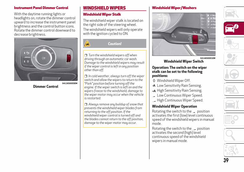
Windshield Wiper/Washers
Operation: The switch on the wiperstalk can be set to the followingpositions:
Windshield Wiper Off.Low Sensitivity Rain Sensing.High Sensitivity Rain Sensing.Low Continuous Wiper Speed.High Continuous Wiper Speed.
Windshield Wiper Operation
Rotating the switch to the positionactivates the first (low) level continuousspeed of the windshield wipers in manualmode.Rotating the switch to the positionactivates the second (high) levelcontinuous speed of the windshieldwipers in manual mode.
04126S0055EM
Dimmer Control
04146S0001EM
Windshield Wiper Switch
39
Rain Sensors
Rotating the switch to the position,activates the first, less sensitive level ofthe Rain Sensing function.Rotating the switch to the position,activates the second, more sensitivelevel of the Rain Sensing function. Referto “Rain Sensor” in this section for moreinformation on how this systemfunctions.
Windshield Washer Operation
Pull the stalk toward the steering wheelto operate the windshield washer.Keep the stalk pulled to activate both thewindshield washer jet and the windshieldwiper with a single movement. The wipersand washers will continue to operate untilyou let go of the stalk.The windshield wiper stops working threestrokes after the stalk is released,followed by a final stroke six secondslater to complete the cycle.
Mist
Use this feature when weatherconditions make occasional usage of thewipers necessary. Push the stalk upwardto the MIST position and release for asingle wiping cycle. This function is usefulto remove small deposits of dust fromthe windshield or morning dew.
Note: This function does not activate thewindshield washer. To spray windshieldwasher fluid onto the windshield, thewashing function must be used.
Warning!
Sudden loss of visibility through thewindshield could lead to a collision. Youmight not see other vehicles or otherobstacles. To avoid sudden icing of thewindshield during freezing weather, warmthe windshield with the defroster before andduring windshield washer use.
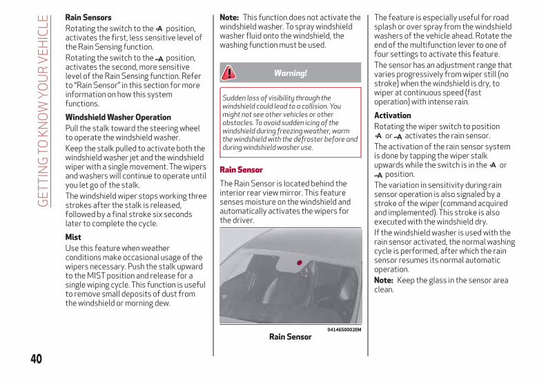
Rain SensorThe Rain Sensor is located behind theinterior rear view mirror. This featuresenses moisture on the windshield andautomatically activates the wipers forthe driver.
The feature is especially useful for roadsplash or over spray from the windshieldwashers of the vehicle ahead. Rotate theend of the multifunction lever to one offour settings to activate this feature.The sensor has an adjustment range thatvaries progressively from wiper still (nostroke) when the windshield is dry, towiper at continuous speed (fastoperation) with intense rain.
Activation
Rotating the wiper switch to positionor activates the rain sensor.
The activation of the rain sensor systemis done by tapping the wiper stalkupwards while the switch is in the or
position.The variation in sensitivity during rainsensor operation is also signaled by astroke of the wiper (command acquiredand implemented). This stroke is alsoexecuted with the windshield dry.If the windshield washer is used with therain sensor activated, the normal washingcycle is performed, after which the rainsensor resumes its normal automaticoperation.Note: Keep the glass in the sensor areaclean.
04146S0002EM
Rain Sensor
40
GE
TT
ING
TOK
NO
WY
OU
RV
EH
ICLE

Deactivation
Use the wiper switch or cycle the ignitionto STOP.If the ignition is cycled to the STOPposition and the wiper switch is left in
or position, no wiping cycle willoccur even if it rains when the vehicle isnext started (ignition at ON).This prevents accidental activation of therain sensor when the engine is started(e.g. when the windshield is being washedby hand or the wipers are stuck to thewindshield by ice).You can restore the automaticfunctioning of the rain sensor by tappingthe wiper stalk upwards once the vehiclehas been restarted.When the rain sensor is reactivated usingany of the functions described above,reactivation is indicated by a single tap ofthe windshield wipers, regardless of thecondition of the windshield.In the event of malfunction of the rainsensor while it is active, the windshieldwiper operates intermittently at a speedconsistent with the sensitivity setting ofthe rain sensor, whether or not there israin on the glass for as long as the sensorfailure is indicated on the display.
The sensor continues to operate and it ispossible to set the windshield wiper tocontinuous mode or . The failureindication remains on for as long as thesensor is active.The rain sensor is able to recognize andautomatically adjust itself in thepresence of the following conditions:
Presence of dirt on the controlledsurface (e.g. salt, dirt, etc.).
Presence of streaks of water causedby the worn window wiper blades.
Difference between day and night.
CLIMATE CONTROLPassenger Compartment Air VentsSide Air Vents
To adjust the position of the Side AirVents, move the Side Air Vent Adjuster(2) in any direction.
Rotate the Side Air Vent Adjuster (2)to adjust the air flow. Rotating the SideAir Vent Adjuster (2) clockwise will closethe vent. Rotating it counterclockwisewill open the vent.
04156S0002EM
Side Air Vents
1 — Demister Air Vents2 — Side Air Vent Adjuster
41

Central Air Vents
To adjust the position of the CentralAir Vents, move the Central Air VentAdjuster (2) up or down.
Rotate the Central Air Vent Air FlowAdjuster (3) to adjust the air flow.Rotating Central Air Vent Air FlowAdjuster (3) up will open the vents,allowing for maximum airflow. Rotating itdown will close the vents.
Rear Air Vents
To adjust the position of the Rear AirVents, move the Rear Air Vent Adjuster(2) in any direction.
Rotate the Rear Air Vent Adjuster (2)to adjust the air flow. Rotating the RearAir Vent Adjuster (2) clockwise will closethe vent. Rotating it counterclockwisewill open the vent.
04156S0003EM
Central Air Vents
1 — Adjustable Central Air Vents2 — Central Air Vent Adjuster3 — Central Air Vent Air Flow Adjuster4 — Windshield Front Defroster Vent
04156S0004EM
Rear Air Vents
1 — Adjustable Rear Air Vents2 — Rear Air Vent Adjuster
42
GE
TT
ING
TOK
NO
WY
OU
RV
EH
ICLE

Automatic Dual-Zone Climate Control SystemControls
04156S0005EM
Automatic Climate Control System
1. Driver Temperature Adjustment Knob 6. Rear Defrost Button 11. Passenger Heated Seat Button —If Equipped
2. Driver Side AUTO Button (AutomaticOperation)
7. Passenger Side Air DistributionSelection Button
12. Air Conditioning On/Off Button
3. Driver Side Air Distribution SelectionButton
8. Passenger Side AUTO Button(Automatic Operation)
13. Steering Wheel Heater Button —If Equipped
4. Front Defrost Button(Rapid Defrosting)
9. Passenger Temperature AdjustmentKnob
14. Driver Side Heated Seat Button —If Equipped
5. Blower Speed Adjustment Knob 10. SYNC Button – Sets TemperatureAlignment Between Driver & PassengerSide
15. Air Recirculation Button
43

Caution!
The system uses R1234yf refrigerant, whichdoes not pollute the environment in theevent of accidental leakage. Under nocircumstances, use R134a and R12 fluids,which are incompatible with the componentsof this system.
DescriptionThe Automatic Dual Zone ClimateControl System adjusts the temperatureand air distribution independentlybetween the driver and passenger.The system maintains the settemperature inside the passengercompartment and compensates foroutside temperature change.Note: The reference temperature is72 °F (22 °C) for optimal comfortmanagement.The automatic setting will adjust thefollowing to maintain comfort within thepassenger compartment:
Air temperature from the driver/frontpassenger side vents
Air distribution from the driver/frontpassenger side vents
Fan speed (continuous variation of theair flow)
Compressor variations (forcooling/dehumidifying the air)
Air recirculation
The Climate Control System can also beoperated manually by using the buttonsand knobs on the faceplate.Manual selections will override theautomatic settings, which are stored untilthe AUTO button is pushed. If the systemintervenes for safety reasons, theautomatic setting will take control of thesystem.The below operations will not deactivatethe automatic (AUTO) function:
Air Recirculation activation/deactivation
A/C activation/deactivation
SYNC function activation
Rear Window Defrost activation/deactivation
When in AUTO mode, the vehicle’sinternal temperature is controlledaccording to the set temperature.The following can be manually set oradjusted:
Driver/passenger air temperature
Blower speed (continuous variation)
Air distribution (seven positions fordriver and passenger)
A/C activation
Front Defroster
Air recirculation
Rear Defroster
System deactivation
Operating ModeThe Climate Control system can beactivated in different ways. It isrecommended to use the automaticfunction. Push the AUTO button and setthe desired temperatures.The automatic system adjusts thetemperature, quantity, and distributionof air introduced into the passengercompartment. It also controls airrecirculation and the activation of the airconditioner.At any time during automatic operation,you can change the temperature, activateor deactivate the Rear Defroster,activate SYNC, activate or deactivatethe air conditioner, and activate ordeactivate air recirculation. The systemwill automatically adjust to the newsettings.
Climate Control Display SettingsThe Climate Control settings are visibleon the Information and EntertainmentSystem radio screen.The display on the Information andEntertainment System is a pop upwindow (1), which is activated by pushingthe buttons or turning the knobs on theClimate Control system. The indicatorlights located on the number of buttonsand knobs indicate that the selectedfeature is on/off. If no operation isperformed for a predetermined time, thepop-up will close on the display.
44
GE
TT
ING
TOK
NO
WY
OU
RV
EH
ICLE

Air Temperature AdjustmentRotate the driver or passengerTemperature Adjustment Knob clockwisefor warmer temperatures orcounterclockwise for coolertemperatures. The set temperatures areshown on the Information andEntertainment System.Push the SYNC button to sync the driverand passenger air temperatures.Rotate the passenger TemperatureAdjustment Knob to cancel the SYNCfunction. This will set a new passengerside temperature.Rotate the Temperature AdjustmentKnob fully clockwise to engage the HI(maximum heating) setting or fullycounterclockwise to engage the LO(maximum cooling) setting. To deactivatethese functions, rotate the TemperatureAdjustment Knob to the desiredtemperature.
Rear passengers’ temperature is linkedto driver side selection.
Air Distribution SelectionPush the Air Distribution Selectionbutton on the faceplate to change themode of air distribution.
Air flow to the windshield anddemister window vents todemist/defrost them.
Air flow at the central and sidedashboard vents to ventilate thechest and the face.
Air flow to the front and rear floorvents. This setting heats thepassenger compartment thequickest.
Air flow distributed between thefloor vents (hotter air) and thecentral and side dashboard vents(cooler air). This air distributionsetting is useful on sunny daysduring spring and autumn.
Air flow distributed between thefloor vents, windshield, and frontside window defrosting/demistingvents. This distribution settingwarms the passenger compartmentwhile preventing the windows fromfogging up.
Air flow distribution between thewindshield demisting/defrostingvents, and side/central dashboardvents. This distribution settingsends air to the windshield in sunnyconditions.
Air flow distribution to all vents onthe vehicle.
In AUTO mode, the Climate Controlsautomatically manage the airdistribution. When set manually, therespective symbols on the Informationand Entertainment System indicate theair distribution setting.
Fan Speed AdjustmentTurn the Blower Speed Knob to increaseor decrease the blower speed. The speedis displayed with lighted indicators in theInformation and Entertainment Systemdisplay.
Maximum fan speed = all indicatorsilluminated on the Information andEntertainment System display
Minimum fan speed = one indicatorilluminated on the Information andEntertainment System display
The fan can be turned off by rotating theBlower Speed Knob counterclockwise toposition O (all segments on theInformation and Entertainment Systemdisplay are turned off).Note: To restore automatic control ofthe fan speed, push the AUTO button.
04156S0006EM
1 — Climate Control Pop-up Display
45

AUTO ButtonWhen the AUTO button is pushed(indicator illuminated), the ClimateControl system automatically adjusts thefollowing settings:
Quantity and distribution of air flow inthe passenger compartment
The air conditioner
Air recirculation
Cancels any manual settings
Selecting the AUTO function illuminatesthe indicator on the A/C button .If air distribution or the fan speed ismanual adjusted, the AUTO buttonindicator will turn off to indicate that theClimate Control system is no longer inAUTO mode.After a manual adjustment, push theAUTO button to resume the automaticsystem.
SYNC ButtonPush the SYNC button (indicatorilluminated) to sync the passenger sideair temperature with the driver side airtemperature.This function makes temperatureregulation easier when the driver istraveling alone.Turn the passenger TemperatureAdjustment Knob or push the passengerside Air Distribution Selection Button tochange the passenger side air
temperature and return to separate airtemperature management.
Air Recirculation And Air QualitySystem (AQS)Air Recirculation is managed according tothe following operating mode:
Automatic engagement: indicator isilluminated above the “A” on the AirRecirculation Button
Forced activation (air circulationalways activated): indicator illuminatedabove the icon on the AirRecirculation Button
Forced deactivation (air recirculationalways off with intake of outside air):both indicators not illuminated on the AirRecirculation Button
The three operating conditions areobtained by pushing the Air RecirculationButton in sequence.
Enabling The Air Quality System (AQS)Function — If Equipped
When the automatic recirculationfunction is selected, the AQS functionautomatically activates internal airrecirculation when the outside air ispolluted (e.g. in heavy traffic and tunnels).At low external temperatures or in highhumidity, the automatic function turnsoff to avoid fogging up the windows. Theuser can select the function again bypushing the Air Recirculation Button.
In automatic operation, air recirculationwill be controlled by the systemaccording to outside environmentalconditions.
Note:
With the AQS function active andafter the internal air recirculationsystem has been functioning for a setamount of time, the Climate ControlSystem enables air intake to cycle theair in the passenger compartment for aset time. The AQS function is disabledduring the air changes.
The engagement of the recirculationsystem makes it possible to reach therequired heating or cooling conditionsfaster. It is, however, inadvisable to useit on rainy/cold days as it can increasethe possibility of the windows fogging.When the outside temperature is low,recirculation is forced off to prevent thewindows from fogging up.
A/C CompressorPush the A/C button to activate ordeactivate the A/C compressor (indicatorilluminated when activated). The A/Ccompressor will remain off even after theengine has stopped.When the A/C compressor is turned off,the system deactivates air recirculationto prevent the windows from fogging up.If the climate control system canmaintain the temperature, with the A/Cturned off, the AUTO feature will remain
46
GE
TT
ING
TOK
NO
WY
OU
RV
EH
ICLE
on and the AUTO button indicator lightwill not switch off.To restore automatic control of the A/Ccompressor, push the A/C button orthe AUTO button. With the A/Ccompressor off, the air speed can be setmanually using the Air Speed AdjustmentKnob.When the A/C compressor is on, and theengine is running, air speed cannot belower than the minimum speed (only oneindicator light is lit).Note: When the A/C is off the ClimateControl system can not produce air thatis colder than the current outsidetemperature. Under certainenvironmental conditions, windows couldfog up rapidly, since the air is notdehumidified.
Front Defroster And MAX-DEFFunctionPush the Front Defroster button
(indicator illuminated) to defrost thewindshield and side windows.While in MAX-DEF function, the airconditioner will:
Activate the air conditionercompressor when the weather allows
Turn air recirculation off
Set the maximum air temperature (HI)on both the driver and passenger side
Activate a blower speed based on thetemperature of the engine coolant
Adjust the air flow towards thewindshield and front side windows
Activate the Rear Window Defroster
Display the fan speed (indicatorsilluminated) and current air distributionsetting
Note: The MAX-DEF function remainsactive for approximately three minutesonce the engine coolant reaches theproper temperature.When the function is on, AUTO mode willdeactivate. The only manual operationspossible are adjusting blower speed andturning off the Rear Window Defroster.Pushing the button switches off theMAX-DEF function.
Rear DefrosterPush the Rear Defroster button toactivate (indicators illuminated) the RearDefroster.The Rear Defroster will turn off after20 minutes or once the engine is turnedoff. To reactive the Rear Defroster, pushthe Rear Defroster button.Note: To avoid damage, do not applystickers over the interior heatingfilaments of the Rear Defroster.
Humidity SensorThe Humidity Sensor helps to prevent thewindows from fogging up. The AUTOfunction (indicator illuminated) must beon for the Humidity Sensor to function.
When outside temperature is low, thesystem may turn the compressor on andturn air recirculation off for safer driving.
Switching Off/On The Climate ControlSystemSwitching Off The Climate ControlSystem
Rotate the Air Speed Adjustment Knobcompletely counterclockwise to turn offthe Climate Control System.With the air conditioner off:
Air recirculation is on
The A/C compressor is off
The fan is off
The heated rear window can beactivated/deactivated
Note: The climate control system storesthe previously set temperatures andresumes operation when any button onthe system is pushed.
Switching On The Climate ControlSystem
To switch the climate control system onin automatic mode, push the AUTObutton.
Stop/StartThe climate control system manages theStop/Start system. Stop/Start has theengine shut off when vehicle speed is0 mph (0 km/h) to maintain comfortwithin the vehicle.
47
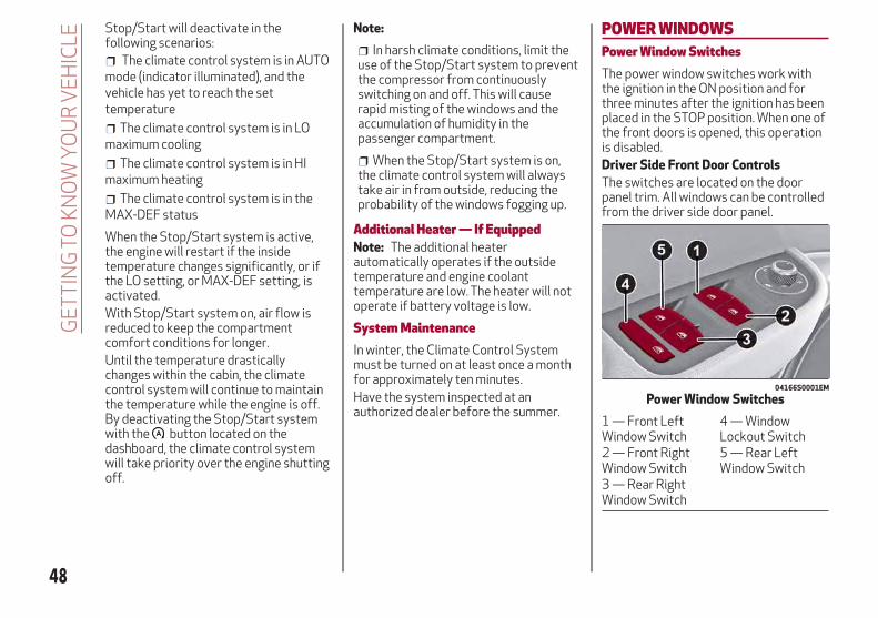
Stop/Start will deactivate in thefollowing scenarios:
The climate control system is in AUTOmode (indicator illuminated), and thevehicle has yet to reach the settemperature
The climate control system is in LOmaximum cooling
The climate control system is in HImaximum heating
The climate control system is in theMAX-DEF status
When the Stop/Start system is active,the engine will restart if the insidetemperature changes significantly, or ifthe LO setting, or MAX-DEF setting, isactivated.With Stop/Start system on, air flow isreduced to keep the compartmentcomfort conditions for longer.Until the temperature drasticallychanges within the cabin, the climatecontrol system will continue to maintainthe temperature while the engine is off.By deactivating the Stop/Start systemwith the button located on thedashboard, the climate control systemwill take priority over the engine shuttingoff.
Note:
In harsh climate conditions, limit theuse of the Stop/Start system to preventthe compressor from continuouslyswitching on and off. This will causerapid misting of the windows and theaccumulation of humidity in thepassenger compartment.
When the Stop/Start system is on,the climate control system will alwaystake air in from outside, reducing theprobability of the windows fogging up.
Additional Heater — If EquippedNote: The additional heaterautomatically operates if the outsidetemperature and engine coolanttemperature are low. The heater will notoperate if battery voltage is low.
System MaintenanceIn winter, the Climate Control Systemmust be turned on at least once a monthfor approximately ten minutes.Have the system inspected at anauthorized dealer before the summer.
POWER WINDOWSPower Window SwitchesThe power window switches work withthe ignition in the ON position and forthree minutes after the ignition has beenplaced in the STOP position. When one ofthe front doors is opened, this operationis disabled.Driver Side Front Door Controls
The switches are located on the doorpanel trim. All windows can be controlledfrom the driver side door panel.
04166S0001EM
Power Window Switches
1 — Front LeftWindow Switch
4 — WindowLockout Switch
2 — Front RightWindow Switch
5 — Rear LeftWindow Switch
3 — Rear RightWindow Switch
48
GE
TT
ING
TOK
NO
WY
OU
RV
EH
ICLE
Window Opening
Briefly push the window switch once tomove the window downward.Push the switch a second time to activatethe automatic operation.Pushing the switch a third time will stopthe window in the desired position.Window Closing
Pull the window switch up to move thewindow upward. Hold the switch for atleast half of a second and the window willgo up automatically.To stop the window during Auto-Upoperation, push or pull the window switchagain.Passenger Side Front Door/Rear DoorControls
There are single window controls on thepassenger and rear door trim panelswhich operate the door windows.Auto-Up Feature With Anti-PinchProtection
The vehicle may be equipped with ananti-pinch safety device for closing thewindows.If the safety system senses any obstaclewhile the window is closing, it will stopthe window’s movement and reverse it,depending on its position.This device is also useful if the windowsare activated accidentally by childreninside the vehicle.
The anti-pinch safety function isactivated both during the manual and theautomatic operation of the window.When the anti-pinch system is activated,the window closing is immediatelyinterrupted. Then the window closing isautomatically reversed and the windowlowers by about eight inches (20 cm) inrelation to the first stop position. Thewindow cannot be operated during thistime.Note: In the event of an error, or if theanti-pinch protection is activated threeconsecutive times, the automatic closingoperation of the window will bedeactivated. In order to restore thecorrect operation of the system, thewindow must be lowered.Power Window System Initialization
If power supply is interrupted, theelectric window automatic operationmust be initialized once more.The initialization procedure describedbelow must be carried out for each door(with the doors closed):
1. Fully close the window to beinitialized, with manual operation.
2. After the window has been closed,hold the up switch for at least threeseconds.
Warning!
Never leave children unattended in a vehicle,and do not let children play with powerwindows. Do not leave the key fob in or nearthe vehicle, or in a location accessible tochildren. Occupants, particularly unattendedchildren, can become entrapped by thewindows while operating the power windowswitches. Such entrapment may result inserious injury or death.
49
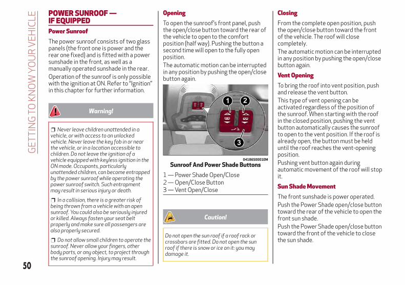
POWER SUNROOF —IF EQUIPPEDPower SunroofThe power sunroof consists of two glasspanels (the front one is power and therear one fixed) and is fitted with a powersunshade in the front, as well as amanually operated sunshade in the rear.Operation of the sunroof is only possiblewith the ignition at ON. Refer to “Ignition”in this chapter for further information.
Warning!
Never leave children unattended in avehicle, or with access to an unlockedvehicle. Never leave the key fob in or nearthe vehicle, or in a location accessible tochildren. Do not leave the ignition of avehicle equipped with keyless ignition in theON mode. Occupants, particularlyunattended children, can become entrappedby the power sunroof while operating thepower sunroof switch. Such entrapmentmay result in serious injury or death.
In a collision, there is a greater risk ofbeing thrown from a vehicle with an opensunroof. You could also be seriously injuredor killed. Always fasten your seat beltproperly and make sure all passengers arealso properly secured.
Do not allow small children to operate thesunroof. Never allow your fingers, otherbody parts, or any object, to project throughthe sunroof opening. Injury may result.
OpeningTo open the sunroof’s front panel, pushthe open/close button toward the rear ofthe vehicle to open to the comfortposition (half way). Pushing the button asecond time will open to the fully openposition.The automatic motion can be interruptedin any position by pushing the open/closebutton again.
Caution!
Do not open the sun roof if a roof rack orcrossbars are fitted. Do not open the sunroof if there is snow or ice on it: you maydamage it.
ClosingFrom the complete open position, pushthe open/close button toward the frontof the vehicle. The roof will closecompletely.The automatic motion can be interruptedin any position by pushing the open/closebutton again.
Vent OpeningTo bring the roof into vent position, pushand release the vent button.This type of vent opening can beactivated regardless of the position ofthe sunroof. When starting with the roofin the closed position, pushing the ventbutton automatically causes the sunroofto open to the vent position. If the roof isalready open, the button must be helduntil the roof reaches the vent-openingposition.Pushing vent button again duringautomatic movement of the roof will stopit.
Sun Shade MovementThe front sunshade is power operated.Push the Power Shade open/close buttontoward the rear of the vehicle to open thefront sun shade.Push the Power Shade open/close buttontoward the front of the vehicle to closethe sun shade.
04186S0001EM
Sunroof And Power Shade Buttons
1 — Power Shade Open/Close2 — Open/Close Button3 — Vent Open/Close
50
GE
TT
ING
TOK
NO
WY
OU
RV
EH
ICLE

The automatic motion can be interruptedin any position by pushing the PowerShade on/off button again.To open the rear sunshade, pull sunshademanually toward the rear of the vehicle.
Pinch Protect FeatureThe sunroof has an anti-pinch safetysystem capable of detecting thepresence of an obstacle during theclosing movement. If an obstacle isdetected, the system intervenes and themovement of the sunroof is immediatelyreversed into opening.
Initialization ProcedureAutomatic operation of the sunroof mustbe initialized again in case of faultysunroof operation. It may also benecessary to initialize the sunroof afterthe vehicle’s battery as beendisconnected and then reconnected.Proceed as follows:
1. Push the open/close button to bringthe roof into the completely closedposition.
2. Cycle the ignition to the STOPposition and wait at least ten seconds.
3. Cycle the ignition to the AVV position.Refer to “Ignition” in this chapter forfurther information.
4. Hold the open/close button down forat least ten seconds. You should thenhear the mechanical stop of the roofmotor.
5. Within five seconds, hold theopen/close button down. The roof willperform a complete automatic openingand closing cycle (to indicate that theinitialization procedure has beensuccessful). If this does not occur, theprocedure must be restarted from thebeginning.
HOODOpeningTo open the hood, proceed as follows:
1. Pull the release lever located on thedriver’s side kick panel.
2. Go to the outside of the vehicle andposition yourself in front of the grille.
3. Lift the hood slightly.
4. Move the under-hood latch from rightto left to release the hood.
04196S0001EM
Hood Release Lever
51

5. Raise the hood completely. Theoperation is assisted by the addition oftwo gas props which hold it in the openposition.
Note:
Do not tamper with the props andassist the hood while lifting it.
Use both hands to lift the hood.Before lifting, check that the windshieldwiper arms are not raised from thewindshield or in operation, that thevehicle is stationary and that the electricpark brake is engaged.
ClosingTo close, lower the hood toapproximately 16 inches (40 cm) fromthe engine compartment then let it drop.Make sure that the hood is completelyclosed and fully latched. Do this by tryingto open it. If it is not perfectly closed, donot try to push the hood lid down, butopen it and repeat the procedure.Note: Always check that the hood isclosed correctly to prevent it fromopening while the vehicle is travelling.Since the hood is equipped with a doublelocking system, one for each side, youmust check that it is closed on both itsside ends.
Warning!
Be sure the hood is fully latched beforedriving your vehicle. If the hood is not fullylatched, it could open when the vehicle is inmotion and block your vision. Failure tofollow this warning could result in seriousinjury or death.
TRUNKThe trunk unlocking is electricallyoperated and is deactivated when thevehicle is in motion.
OpeningOpening From The Outside
When unlocked, the trunk lid can beopened from outside the vehicle usingthe exterior trunk lid release buttonlocated between the plate lights. Pushthe button until you hear a “click.” Thetrunk lid can also be opened by quicklypushing the exterior trunk lid releasebutton on the key fob twice.
The turn signal indicators will blink andthe interior lights will turn on when thetrunk lid is opened. They turn offautomatically when the trunk lid isclosed.The lights turn off automatically after afew minutes if the trunk lid is left open.
04196S0002EM
Lift Under Hood Latch Up Then Left
04056S0005EM
Exterior Trunk Lid Release Button
52
GE
TT
ING
TOK
NO
WY
OU
RV
EH
ICLE
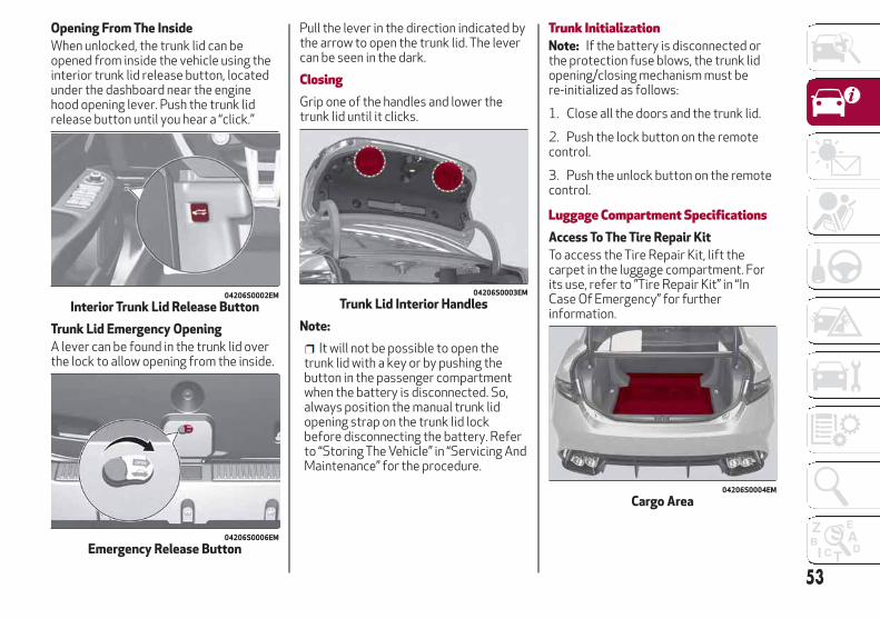
Opening From The Inside
When unlocked, the trunk lid can beopened from inside the vehicle using theinterior trunk lid release button, locatedunder the dashboard near the enginehood opening lever. Push the trunk lidrelease button until you hear a “click.”
Trunk Lid Emergency Opening
A lever can be found in the trunk lid overthe lock to allow opening from the inside.
Pull the lever in the direction indicated bythe arrow to open the trunk lid. The levercan be seen in the dark.
ClosingGrip one of the handles and lower thetrunk lid until it clicks.
Note:
It will not be possible to open thetrunk lid with a key or by pushing thebutton in the passenger compartmentwhen the battery is disconnected. So,always position the manual trunk lidopening strap on the trunk lid lockbefore disconnecting the battery. Referto “Storing The Vehicle” in “Servicing AndMaintenance” for the procedure.
Trunk InitializationNote: If the battery is disconnected orthe protection fuse blows, the trunk lidopening/closing mechanism must bere-initialized as follows:
1. Close all the doors and the trunk lid.
2. Push the lock button on the remotecontrol.
3. Push the unlock button on the remotecontrol.
Luggage Compartment SpecificationsAccess To The Tire Repair Kit
To access the Tire Repair Kit, lift thecarpet in the luggage compartment. Forits use, refer to ”Tire Repair Kit” in “InCase Of Emergency” for furtherinformation.
04206S0002EM
Interior Trunk Lid Release Button
04206S0006EM
Emergency Release Button
04206S0003EM
Trunk Lid Interior Handles
04206S0004EM
Cargo Area
53
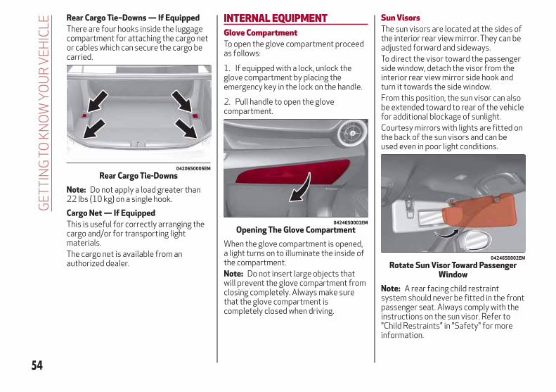
Rear Cargo Tie–Downs — If Equipped
There are four hooks inside the luggagecompartment for attaching the cargo netor cables which can secure the cargo becarried.
Note: Do not apply a load greater than22 lbs (10 kg) on a single hook.
Cargo Net — If Equipped
This is useful for correctly arranging thecargo and/or for transporting lightmaterials.The cargo net is available from anauthorized dealer.
INTERNAL EQUIPMENTGlove CompartmentTo open the glove compartment proceedas follows:
1. If equipped with a lock, unlock theglove compartment by placing theemergency key in the lock on the handle.
2. Pull handle to open the glovecompartment.
When the glove compartment is opened,a light turns on to illuminate the inside ofthe compartment.Note: Do not insert large objects thatwill prevent the glove compartment fromclosing completely. Always make surethat the glove compartment iscompletely closed when driving.
Sun VisorsThe sun visors are located at the sides ofthe interior rear view mirror. They can beadjusted forward and sideways.To direct the visor toward the passengerside window, detach the visor from theinterior rear view mirror side hook andturn it towards the side window.From this position, the sun visor can alsobe extended toward to rear of the vehiclefor additional blockage of sunlight.Courtesy mirrors with lights are fitted onthe back of the sun visors and can beused even in poor light conditions.
Note: A rear facing child restraintsystem should never be fitted in the frontpassenger seat. Always comply with theinstructions on the sun visor. Refer to"Child Restraints" in "Safety" for moreinformation.
04206S0005EM
Rear Cargo Tie-Downs
04246S0001EM
Opening The Glove Compartment
04246S0002EM
Rotate Sun Visor Toward PassengerWindow
54
GE
TT
ING
TOK
NO
WY
OU
RV
EH
ICLE

Homelink — If EquippedDescription
Homelink is a fixed system installed onthe vehicle. It can sync up to threedifferent devices that activate garagedoors, gates, lighting systems, and homeor office alarm systems.
Programming
Warning!
Vehicle exhaust contains carbonmonoxide, a dangerous gas. Do not run yourvehicle in the garage while programming thetransceiver. Exhaust gas can cause seriousinjury or death.
Your motorized door or gate will open andclose while you are programming theuniversal transceiver. Do not program thetransceiver if people, pets or other objectsare in the path of the door or gate. Only usethis transceiver with a garage door openerthat has a “stop and reverse” feature asrequired by Federal safety standards. Thisincludes most garage door opener modelsmanufactured after 1982. Do not use agarage door opener without these safetyfeatures. Call toll-free 1-800-355-3515 or,on the Internet at HomeLink.com for safetyinformation or assistance.
Note: Without starting the engine,activate the handbrake and place theignition in the ON position.
The following operation will delete themanufacture’s standard codes and doesnot need to be repeated during thesubsequent button programming:
Push and hold the outer buttons (1 and3). After about ten seconds, the lightedindicators will start to flash. Release bothbuttons.
Note: Follow the steps below to beginprogramming your remote control to oneof the HomeLink buttons:
1. Push and hold the desired HomeLinkbutton (1, 2 or 3).When the HomeLink indicator begins toflash slowly, move the portable remotecontrol one to three inches from the
HomeLink system (keeping theprogrammable button pushed down).
2. If the indicator does not begin to flashquickly, change the distance between theHomeLink and the portable remotecontrol and try the procedure again.
3. The HomeLink indicator flashes, firstslowly and then quickly. When theindicator starts to flash quickly, releaseboth buttons.
Using The Homelink System
The HomeLink system activates thegarage door or gate motor, just like theportable remote control. The car must bewithin the range of the garage door andthe ignition must be in the ON position.Push the programmed button (1, 2 or 3).While the signal is being transmitted, theindicator is lit and the system (garagedoor, gate, etc.) will respond.If the HomeLink system does notoperate, the original portable remotecontrol may be equipped with analternative code (refer to “AlternativeCode Synchronization”).If necessary, the original remote controlcan still be used to operate the system.
Alternative Code Synchronization
To check whether the garage door or gatemotor has an alternative code, proceedas follows:
1. Read the garage door or gate motormanufacturer manual.
04246S0006NA
Garage Door Opener (Homelink)Buttons
1 — Homelink Button 12 — Homelink Button 23 — Homelink Button 34 — Homelink Indicator
55
2. The portable remote control seems tohave programmed to the HomeLinksystem, but the garage door or gate canbe neither opened or closed.
3. Push the programmed button andkeep it pushed (1, 2 or 3). With analternative code system, the indicatorflashes briefly, and then remains off fortwo seconds. This sequence is repeatedfor 20 seconds.
Warning!
Vehicle exhaust contains carbonmonoxide, a dangerous gas. Do not run yourvehicle in the garage while programming thetransceiver. Exhaust gas can cause seriousinjury or death.
Your motorized door or gate will open andclose while you are programming theuniversal transceiver. Do not program thetransceiver if people, pets or other objectsare in the path of the door or gate. Only usethis transceiver with a garage door openerthat has a “stop and reverse” feature asrequired by Federal safety standards. Thisincludes most garage door opener modelsmanufactured after 1982. Do not use agarage door opener without these safetyfeatures. Call toll-free 1-800-355-3515 or,on the Internet at HomeLink.com for safetyinformation or assistance.
Note: To program Homelink using anAlternative Code, the car must be withinrange of the garage door. Activate the
handbrake and turn the ignition to ON,without starting the engine.Proceed as follows:
1. Locate the “Learn” or “Train” button onthe garage door or gate motor. The colorand position may vary depending on themanufacturer (consult the garage door orgate manual). Push the “Learn” or “Train”button (this normally activates thesetting warning light).
2. Push the desired HomeLink button (1,2 or 3). When the HomeLink indicatorbegins to flash slowly, move the portableremote control one to three inches fromthe HomeLink system (keeping theprogrammable button pushed down).
3. Within 30 seconds, push theprogrammed key (1, 2 or 3) and release it.Push the programmed button a secondtime and release it to conclude theoperation. For some motors, theoperation will probably have to berepeated a third time to end the setting.
The motor should now be capable ofrecognizing the signal transmitted byHomeLink and then open/close the dooror gate.
Programming A Single Key
It is possible to program another originalremote control on an alreadyprogrammed HomeLink key by cancelingthe previously stored frequency.
Warning!
Vehicle exhaust contains carbonmonoxide, a dangerous gas. Do not run yourvehicle in the garage while programming thetransceiver. Exhaust gas can cause seriousinjury or death.
Your motorized door or gate will open andclose while you are programming theuniversal transceiver. Do not program thetransceiver if people, pets or other objectsare in the path of the door or gate. Only usethis transceiver with a garage door openerthat has a “stop and reverse” feature asrequired by Federal safety standards. Thisincludes most garage door opener modelsmanufactured after 1982. Do not use agarage door opener without these safetyfeatures. Call toll-free 1-800-355-3515 or,on the Internet at HomeLink.com for safetyinformation or assistance.
Note: Activate the handbrake and placethe ignition to ON without starting theengine.Proceed as follows:
1. Push the desired HomeLink buttonand keep it pushed (1, 2 or 3). Do notrelease the button until the lastoperation has been performed.
56
GE
TT
ING
TOK
NO
WY
OU
RV
EH
ICLE
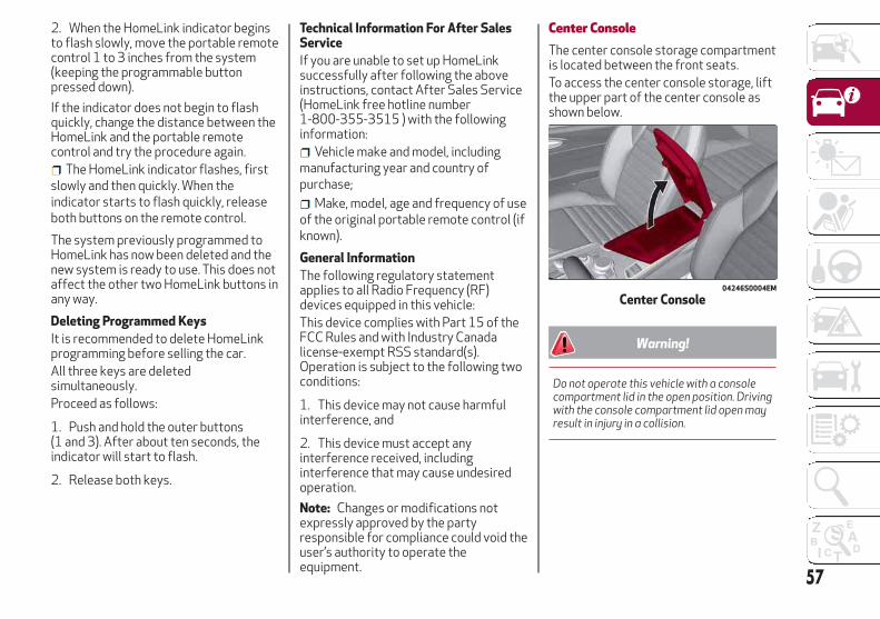
2. When the HomeLink indicator beginsto flash slowly, move the portable remotecontrol 1 to 3 inches from the system(keeping the programmable buttonpressed down).
If the indicator does not begin to flashquickly, change the distance between theHomeLink and the portable remotecontrol and try the procedure again.
The HomeLink indicator flashes, firstslowly and then quickly. When theindicator starts to flash quickly, releaseboth buttons on the remote control.
The system previously programmed toHomeLink has now been deleted and thenew system is ready to use. This does notaffect the other two HomeLink buttons inany way.
Deleting Programmed Keys
It is recommended to delete HomeLinkprogramming before selling the car.All three keys are deletedsimultaneously.Proceed as follows:
1. Push and hold the outer buttons(1 and 3). After about ten seconds, theindicator will start to flash.
2. Release both keys.
Technical Information For After SalesService
If you are unable to set up HomeLinksuccessfully after following the aboveinstructions, contact After Sales Service(HomeLink free hotline number1-800-355-3515 ) with the followinginformation:
Vehicle make and model, includingmanufacturing year and country ofpurchase;
Make, model, age and frequency of useof the original portable remote control (ifknown).
General Information
The following regulatory statementapplies to all Radio Frequency (RF)devices equipped in this vehicle:This device complies with Part 15 of theFCC Rules and with Industry Canadalicense-exempt RSS standard(s).Operation is subject to the following twoconditions:
1. This device may not cause harmfulinterference, and
2. This device must accept anyinterference received, includinginterference that may cause undesiredoperation.
Note: Changes or modifications notexpressly approved by the partyresponsible for compliance could void theuser’s authority to operate theequipment.
Center ConsoleThe center console storage compartmentis located between the front seats.To access the center console storage, liftthe upper part of the center console asshown below.
Warning!
Do not operate this vehicle with a consolecompartment lid in the open position. Drivingwith the console compartment lid open mayresult in injury in a collision.
04246S0004EM
Center Console
57

CupholderTwo cupholders are available in thecenter console.
To access the cupholders, slide the coverforward. To close the compartment, pushthe cover and it will close automatically.
ENVIRONMENTAL PROTECTIONSYSTEMSThe following systems are used forreducing engine emissions:
Catalytic Converter
Oxygen Sensors
Evaporation Control System
ACTIVE AERODYNAMICSFront Mobile Spoiler (Alfa Active Aero)This is an automatic device, working atthe vehicle speed, which allows higherreactivity at average speeds and highervehicle stability at high speeds,regulating the air flow into the lower partof the vehicle.Note: The system is not active intemperatures near or below zero, orwhen the Alfa DNA selector is in the"Natural" or "Advanced Efficiency"positions.
If there is a fault, a generic failure iconwill light up on the instrument paneldisplay, along with a message that willidentify the type of malfunction. See yourauthorized dealer if a fault occurs.
04246S0005EM
Cupholders In Center Console
1— Cover
04296S0001EM
Front Fascia
58
GE
TT
ING
TOK
NO
WY
OU
RV
EH
ICLE

GETTING TO KNOW YOUR INSTRUMENT PANEL
This section gives you all the informationyou need to understand and usethe instrument panel correctly.
INSTRUMENT PANEL FEATURES . . .60INSTRUMENT CLUSTER DISPLAY . .62WARNING LIGHTS AND MESSAGESON THE INSTRUMENT PANEL . . . . .67ONBOARD DIAGNOSTIC SYSTEM . . .89
59
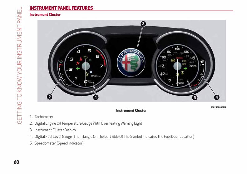
INSTRUMENT PANEL FEATURESInstrument Cluster
1. Tachometer
2. Digital Engine Oil Temperature Gauge With Overheating Warning Light
3. Instrument Cluster Display
4. Digital Fuel Level Gauge (The Triangle On The Left Side Of The Symbol Indicates The Fuel Door Location)
5. Speedometer (Speed Indicator)
05026S0005EM
Instrument Cluster
60
GE
TT
ING
TOK
NO
WY
OU
RIN
ST
RU
ME
NT
PAN
EL
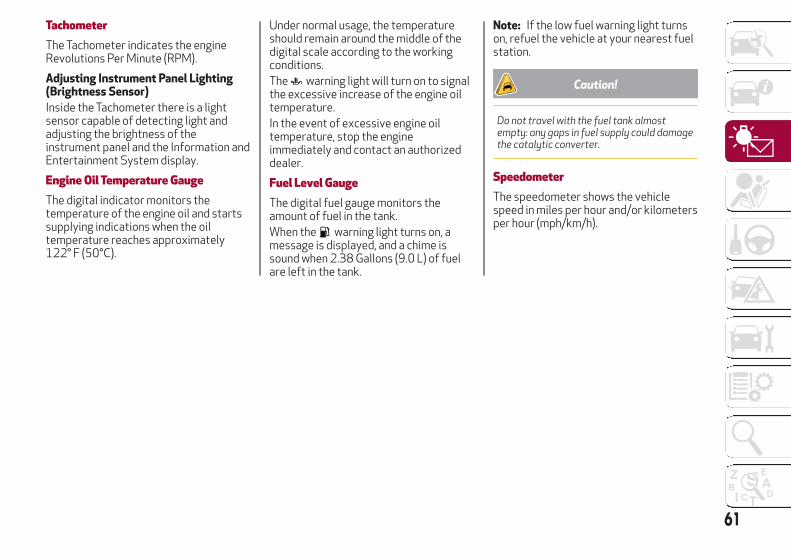
TachometerThe Tachometer indicates the engineRevolutions Per Minute (RPM).
Adjusting Instrument Panel Lighting(Brightness Sensor)
Inside the Tachometer there is a lightsensor capable of detecting light andadjusting the brightness of theinstrument panel and the Information andEntertainment System display.
Engine Oil Temperature GaugeThe digital indicator monitors thetemperature of the engine oil and startssupplying indications when the oiltemperature reaches approximately122° F (50°C).
Under normal usage, the temperatureshould remain around the middle of thedigital scale according to the workingconditions.The warning light will turn on to signalthe excessive increase of the engine oiltemperature.In the event of excessive engine oiltemperature, stop the engineimmediately and contact an authorizeddealer.
Fuel Level GaugeThe digital fuel gauge monitors theamount of fuel in the tank.When the warning light turns on, amessage is displayed, and a chime issound when 2.38 Gallons (9.0 L) of fuelare left in the tank.
Note: If the low fuel warning light turnson, refuel the vehicle at your nearest fuelstation.
Caution!
Do not travel with the fuel tank almostempty: any gaps in fuel supply could damagethe catalytic converter.
SpeedometerThe speedometer shows the vehiclespeed in miles per hour and/or kilometersper hour (mph/km/h).
61
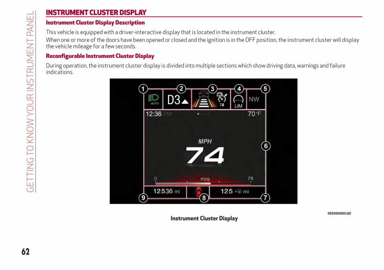
INSTRUMENT CLUSTER DISPLAYInstrument Cluster Display DescriptionThis vehicle is equipped with a driver-interactive display that is located in the instrument cluster.When one or more of the doors have been opened or closed and the ignition is in the OFF position, the instrument cluster will displaythe vehicle mileage for a few seconds.
Reconfigurable Instrument Cluster DisplayDuring operation, the instrument cluster display is divided into multiple sections which show driving data, warnings and failureindications.
05036S0001QV
Instrument Cluster Display
62
GE
TT
ING
TOK
NO
WY
OU
RIN
ST
RU
ME
NT
PAN
EL
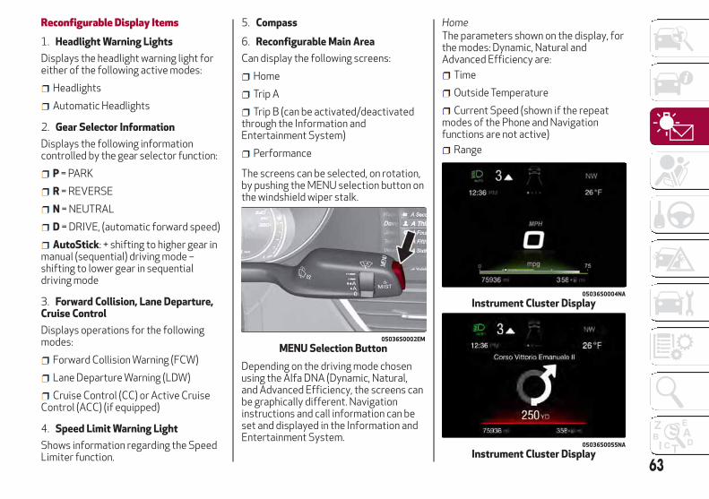
Reconfigurable Display Items
1. Headlight Warning Lights
Displays the headlight warning light foreither of the following active modes:
Headlights
Automatic Headlights
2. Gear Selector Information
Displays the following informationcontrolled by the gear selector function:
P = PARK
R = REVERSE
N = NEUTRAL
D = DRIVE, (automatic forward speed)
AutoStick: + shifting to higher gear inmanual (sequential) driving mode –shifting to lower gear in sequentialdriving mode
3. Forward Collision, Lane Departure,Cruise Control
Displays operations for the followingmodes:
Forward Collision Warning (FCW)
Lane Departure Warning (LDW)
Cruise Control (CC) or Active CruiseControl (ACC) (if equipped)
4. Speed Limit Warning Light
Shows information regarding the SpeedLimiter function.
5. Compass
6. Reconfigurable Main Area
Can display the following screens:
Home
Trip A
Trip B (can be activated/deactivatedthrough the Information andEntertainment System)
Performance
The screens can be selected, on rotation,by pushing the MENU selection button onthe windshield wiper stalk.
Depending on the driving mode chosenusing the Alfa DNA (Dynamic, Natural,and Advanced Efficiency, the screens canbe graphically different. Navigationinstructions and call information can beset and displayed in the Information andEntertainment System.
HomeThe parameters shown on the display, forthe modes: Dynamic, Natural andAdvanced Efficiency are:
Time
Outside Temperature
Current Speed (shown if the repeatmodes of the Phone and Navigationfunctions are not active)
Range
05036S0002EM
MENU Selection Button
05036S0004NA
Instrument Cluster Display
05036S0055NA
Instrument Cluster Display63
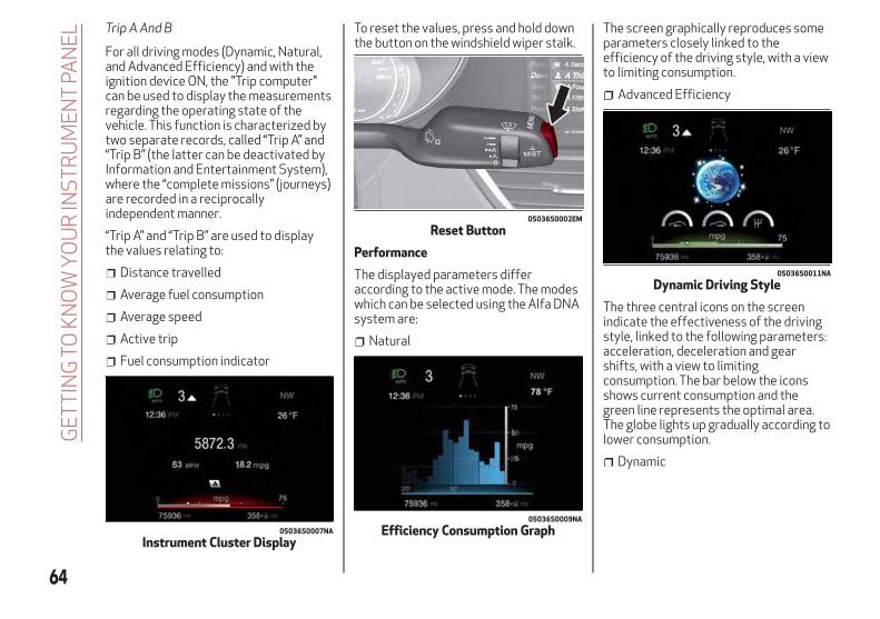
Trip A And B
For all driving modes (Dynamic, Natural,and Advanced Efficiency) and with theignition device ON, the "Trip computer"can be used to display the measurementsregarding the operating state of thevehicle. This function is characterized bytwo separate records, called “Trip A” and“Trip B” (the latter can be deactivated byInformation and Entertainment System),where the “complete missions” (journeys)are recorded in a reciprocallyindependent manner.
“Trip A” and “Trip B” are used to displaythe values relating to:
Distance travelled
Average fuel consumption
Average speed
Active trip
Fuel consumption indicator
To reset the values, press and hold downthe button on the windshield wiper stalk.
Performance
The displayed parameters differaccording to the active mode. The modeswhich can be selected using the Alfa DNAsystem are:
Natural
The screen graphically reproduces someparameters closely linked to theefficiency of the driving style, with a viewto limiting consumption.
Advanced Efficiency
The three central icons on the screenindicate the effectiveness of the drivingstyle, linked to the following parameters:acceleration, deceleration and gearshifts, with a view to limitingconsumption. The bar below the iconsshows current consumption and thegreen line represents the optimal area.The globe lights up gradually according tolower consumption.
Dynamic
05036S0007NA
Instrument Cluster Display
05036S0002EM
Reset Button
05036S0009NA
Efficiency Consumption Graph
05036S0011NA
Dynamic Driving Style
64
GE
TT
ING
TOK
NO
WY
OU
RIN
ST
RU
ME
NT
PAN
EL

The displayed parameters are related tovehicle stability, the graphs illustrate thetrend of the longitudinal/lateralaccelerations (G-meter information),considering gravity acceleration as areference unit.
Lateral acceleration peaks are alsoindicated.
The displayed parameters are related tovehicle stability, the graphs illustrate thetrend of the longitudinal/lateralaccelerations (G-meter information),considering gravity acceleration as areference unit.
Lateral acceleration peaks are alsoindicated.
7. Vehicle Range
Indicates the miles left before the fueltank is empty.
Displays the position by indicating thecardinal direction.
8. Failure Warning Lights
Area dedicated to displaying failures, thefollowing symbols could be displayed onrotation:
Low criticality symbols (yellow amber)
High criticality symbols (red)
9. Odometer
Indicates the total miles travelled.
U.S. Federal regulations require thatupon transfer of vehicle ownership, theseller certify to the purchaser the correctmileage that the vehicle has been driven.If your odometer needs to be repaired orserviced, the repair technician shouldleave the odometer reading the same asit was before the repair or service. If s/hecannot do so, then the odometer must beset at zero, and a sticker must be placed
in the door jamb stating what the mileagewas before the repair or service. It is agood idea for you to make a record of theodometer reading before therepair/service, so that you can be surethat it is properly reset, or that the doorjamb sticker is accurate if the odometermust be reset at zero.
PARAMETERS SET BY USER
Multiple settings can be programmed bythe user using the Information andEntertainment System. This sectiondescribes only the basic settings:
Units & Language
Time & Date
Cluster
To access the settings list in theInformation and Entertainment System,proceed as follows:1. Press the MENU button to access the
main menu.
05036S0013NA
Acceleration Gauge
05036S0014NA
Acceleration Stability Gauge
05036S0015EM
Information And Entertainment System
65
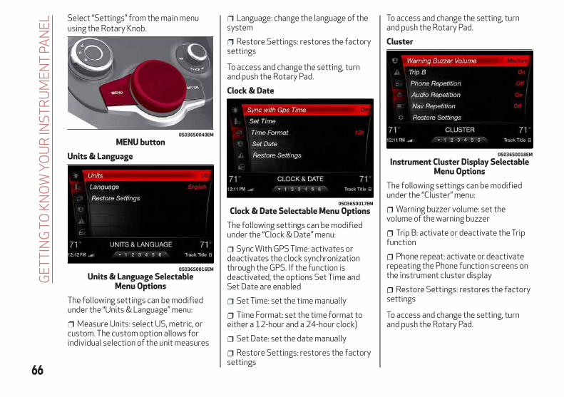
Select “Settings” from the main menuusing the Rotary Knob.
Units & Language
The following settings can be modifiedunder the “Units & Language” menu:
Measure Units: select US, metric, orcustom. The custom option allows forindividual selection of the unit measures
Language: change the language of thesystem
Restore Settings: restores the factorysettings
To access and change the setting, turnand push the Rotary Pad.
Clock & Date
The following settings can be modifiedunder the “Clock & Date” menu:
Sync With GPS Time: activates ordeactivates the clock synchronizationthrough the GPS. If the function isdeactivated, the options Set Time andSet Date are enabled
Set Time: set the time manually
Time Format: set the time format toeither a 12-hour and a 24-hour clock)
Set Date: set the date manually
Restore Settings: restores the factorysettings
To access and change the setting, turnand push the Rotary Pad.
Cluster
The following settings can be modifiedunder the “Cluster” menu:
Warning buzzer volume: set thevolume of the warning buzzer
Trip B: activate or deactivate the Tripfunction
Phone repeat: activate or deactivaterepeating the Phone function screens onthe instrument cluster display
Restore Settings: restores the factorysettings
To access and change the setting, turnand push the Rotary Pad.
05036S0040EM
MENU button
05036S0016EM
Units & Language SelectableMenu Options
05036S0017EM
Clock & Date Selectable Menu Options
05036S0018EM
Instrument Cluster Display SelectableMenu Options
66
GE
TT
ING
TOK
NO
WY
OU
RIN
ST
RU
ME
NT
PAN
EL

WARNING LIGHTS ANDMESSAGES ON THEINSTRUMENT PANELThe following pages consist of warninglights and messages.
Note:
The warning light turns on togetherwith a dedicated message and/or chimewhen applicable. These indications areprecautionary and as such must not beconsidered as exhaustive and/oralternative to the information containedin the Owner’s Manual, which you areadvised to read carefully in all cases.Always refer to the information in thissection in the event of a failureindication.
The failure indicators appearing onthe display are divided into twocategories: very serious and less seriousfaults. Serious faults are indicated by arepeated and prolonged warning "cycle.”Less serious faults are indicated by awarning "cycle" with a shorter duration.You can stop the warning cycle in bothcases by pushing the button located onthe windshield wiper stalk. Theinstrument panel warning light will stayon until the cause of the failure iseliminated.
67

Red Warning Lights
Warning Light What It Means What To Do
INSUFFICIENT BRAKE FLUID/ELECTRIC PARK BRAKEONThis light monitors various brake functions, includingbrake fluid level and parking brake application. If thebrake light turns on it may indicate that the parking brakeis applied, that the brake fluid level is low, or that there isa problem with the anti-lock brake system reservoir.If the light remains on when the parking brake has beendisengaged, and the fluid level is at the full mark on themaster cylinder reservoir, it indicates a possible brakehydraulic system malfunction or that a problem with theBrake Booster has been detected by the Anti-Lock BrakeSystem (ABS) / Electronic Stability Control (ESC) system.In this case, the light will remain on until the condition hasbeen corrected. If the problem is related to the BrakeBooster, the ABS pump will run when applying the brake,and a brake pedal pulsation may be felt during each stop.
For low brake fluid level, go to an authorized dealer tohave the system checked as soon as possible.Release the electric park brake, then check that thewarning light has turned off.If the warning light stays on, contact an authorized dealer.
ELECTRONIC BRAKING FORCE DISTRIBUTION (EBD)FAILUREThe simultaneous turning on of the BRAKE (red) and
(amber) warning lights with the engine on indicateseither a failure of the EBD system or that the system isnot available. In this case, the rear wheels may suddenlylock and the vehicle may swerve when braking abruptly.
Drive very carefully to the nearest authorized dealer tohave the system inspected immediately.
68
GE
TT
ING
TOK
NO
WY
OU
RIN
ST
RU
ME
NT
PAN
EL
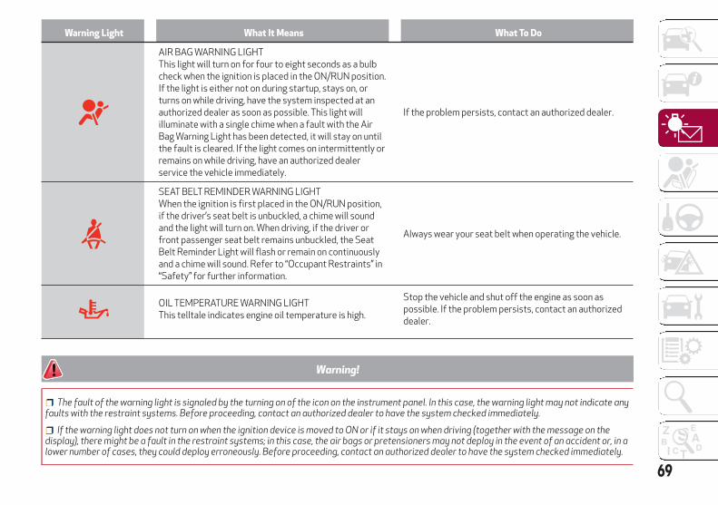
Warning Light What It Means What To Do
AIR BAG WARNING LIGHTThis light will turn on for four to eight seconds as a bulbcheck when the ignition is placed in the ON/RUN position.If the light is either not on during startup, stays on, orturns on while driving, have the system inspected at anauthorized dealer as soon as possible. This light willilluminate with a single chime when a fault with the AirBag Warning Light has been detected, it will stay on untilthe fault is cleared. If the light comes on intermittently orremains on while driving, have an authorized dealerservice the vehicle immediately.
If the problem persists, contact an authorized dealer.
SEAT BELT REMINDER WARNING LIGHTWhen the ignition is first placed in the ON/RUN position,if the driver’s seat belt is unbuckled, a chime will soundand the light will turn on. When driving, if the driver orfront passenger seat belt remains unbuckled, the SeatBelt Reminder Light will flash or remain on continuouslyand a chime will sound. Refer to “Occupant Restraints” in“Safety” for further information.
Always wear your seat belt when operating the vehicle.
OIL TEMPERATURE WARNING LIGHTThis telltale indicates engine oil temperature is high.
Stop the vehicle and shut off the engine as soon aspossible. If the problem persists, contact an authorizeddealer.
Warning!
The fault of the warning light is signaled by the turning on of the icon on the instrument panel. In this case, the warning light may not indicate anyfaults with the restraint systems. Before proceeding, contact an authorized dealer to have the system checked immediately.
If the warning light does not turn on when the ignition device is moved to ON or if it stays on when driving (together with the message on thedisplay), there might be a fault in the restraint systems; in this case, the air bags or pretensioners may not deploy in the event of an accident or, in alower number of cases, they could deploy erroneously. Before proceeding, contact an authorized dealer to have the system checked immediately.
69

Amber Warning Lights
WarningLight What It Means What To Do
ANTI-LOCK BRAKE (ABS) INDICATOR LIGHTThis light monitors the Anti-Lock Brake System (ABS). The lightwill turn on when the ignition is placed in the ON/RUN positionand may stay on for as long as four seconds.If the ABS light remains on or turns on while driving, then theAnti-Lock portion of the brake system is not functioning andservice is required. However, the conventional brake system willcontinue to operate normally if the brake indicator light is noton.If the ABS light is on, the brake system should be serviced assoon as possible to restore the benefits of Anti-Lock Brakes. Ifthe ABS light does not turn on when the ignition is placed in theON/RUN position, have the light inspected by an authorizeddealer.
Drive carefully and contact an authorized dealer as soon aspossible.
TIRE PRESSURE MONITORING INDICATOR LIGHTThe warning light switches on and a message is displayed toindicate that the tire pressure is lower than the recommendedvalue and/or that slow pressure loss is occurring. In these cases,optimal tire duration and fuel consumption may not beguaranteed.Should one or more tires be in the condition mentioned above,the display will show the indications corresponding to each tirein sequence.
Continue driving for up to 50 miles (80 km) at a speed no higherthen 50 mph (80 km/h). Contact an authorized dealer to havethe tire repaired.
70
GE
TT
ING
TOK
NO
WY
OU
RIN
ST
RU
ME
NT
PAN
EL

Each tire, including the spare (ifprovided), should be checked monthlywhen cold and inflated to the inflationpressure recommended by the vehiclemanufacturer on the vehicle placard ortire inflation pressure label. (If yourvehicle has tires of a different size thanthe size indicated on the vehicle placardor tire inflation pressure label, you shoulddetermine the proper tire inflationpressure for those tires.)As an added safety feature, your vehiclehas been equipped with a Tire PressureMonitoring System (TPMS) thatilluminates a low tire pressure telltalewhen one or more of your tires issignificantly under-inflated. Accordingly,when the low tire pressure telltaleilluminates, you should stop and checkyour tires as soon as possible and inflatethem to the proper pressure. Driving on asignificantly under-inflated tire causesthe tire to overheat and can lead to tirefailure. Under-inflation also reduces fuelefficiency and tire tread life, and mayaffect the vehicle’s handling and stoppingability.Please note that the TPMS is not asubstitute for proper tire maintenance,and it is the driver’s responsibility tomaintain correct tire pressure, even ifunder-inflation has not reached the levelto trigger illumination of the TPMS lowtire pressure telltale.
Your vehicle has also been equipped witha TPMS malfunction indicator to indicatewhen the system is not operatingproperly. The TPMS malfunctionindicator is combined with the low tirepressure telltale. When the systemdetects a malfunction, the telltale willflash for approximately one minute andthen remain continuously illuminated.This sequence will continue uponsubsequent vehicle start-ups as long asthe malfunction exists. When themalfunction indicator is illuminated, thesystem may not be able to detect orsignal low tire pressure as intended.TPMS malfunctions may occur for avariety of reasons, including theinstallation of replacement or alternatetires or wheels on the vehicle thatprevent the TPMS from functioningproperly. Always check the TPMSmalfunction telltale after replacing oneor more tires or wheels on your vehicle, toensure that the replacement or alternatetires and wheels allow the TPMS tocontinue to function properly.
Caution!
The TPMS has been optimized for theoriginal equipment tires and wheels. TPMSpressures and warning have beenestablished for the tire size equipped onyour vehicle. Undesirable system operationor sensor damage may result when usingreplacement equipment that is not of thesame size, type, and/or style. Aftermarketwheels can cause sensor damage. Usingaftermarket tire sealants may cause theTire Pressure Monitoring System (TPMS)sensor to become inoperable. After using anaftermarket tire sealant it is recommendedthat you take your vehicle to an authorizeddealership to have your sensor functionchecked.
71

Warning Light What It Means What To Do
Tire Pressure LowThe indicator light will illuminate to indicate that the tirepressure is lower than the recommended value and/or thatslow pressure loss is occurring. In these cases, optimal tireduration and fuel consumption may not be guaranteed.
In any situation in which the message on the display is "SeeManual", it is ESSENTIAL to refer to “Auxiliary DrivingSystems” in “Safety,” strictly complying with theindications that you find there.
ELECTRONIC STABILITY CONTROL (ESC) INDICATORLIGHTWhen the ignition is cycled to ON, the indicator lightilluminates, but should turn off as soon as the engine isstarted.ESC System Intervention: Intervention by the system isindicated by the flashing of the indicator light: it indicatesthat the vehicle is in critical stability and grip conditions.
ESC System Failure: If the indicator light does not turn off,or if it stays on with the engine running, a failure was foundin the ESC system. In these cases, contact an authorized dealer as soon as
possible.Hill Start Assist System Failure: The illumination of theindicator light indicates a Hill Start Assist system failure.
ELECTRONIC STABILITY CONTROL (ESC) OFFINDICATOR LIGHT — IF EQUIPPEDWhen the ignition is cycled to ON, the indicator lightilluminates, but should turn off as soon as the engine isstarted.The indicator light illuminates to indicate that some activesafety systems have been partially or totally deactivated.For further details about the active safety systems, referto “Active Safety Systems” in “Safety.” When the activesafety systems are reactivated, the indicator light turnsoff.
72
GE
TT
ING
TOK
NO
WY
OU
RIN
ST
RU
ME
NT
PAN
EL

Warning Light What It Means What To Do
REAR FOG LIGHTThe indicator illuminates when the rear fog light isactivated.
ENGINE CHECK/MALFUNCTION INDICATOR LIGHT (MIL)In normal conditions, when the ignition is cycled to ON, theindicator light illuminates, but it should turn off as soon asthe engine is started.The operation of the indicator light may be checked by thetraffic police using specific devices. Comply with the lawsand regulations of the country where you are driving.
Under these conditions, the vehicle can continue travellingat moderate speed but without demanding excessiveeffort from the engine or high speed. Prolonged use of thevehicle with the indicator light on constantly may causedamage. Contact an authorized dealer as soon as possible.
Caution!
If, turning the ignition device to ON, the warning light does not turn on or if it turns on steadily or flashing when travelling (on some versionstogether with the message on the display), contact an authorized dealer as soon as possible.
73
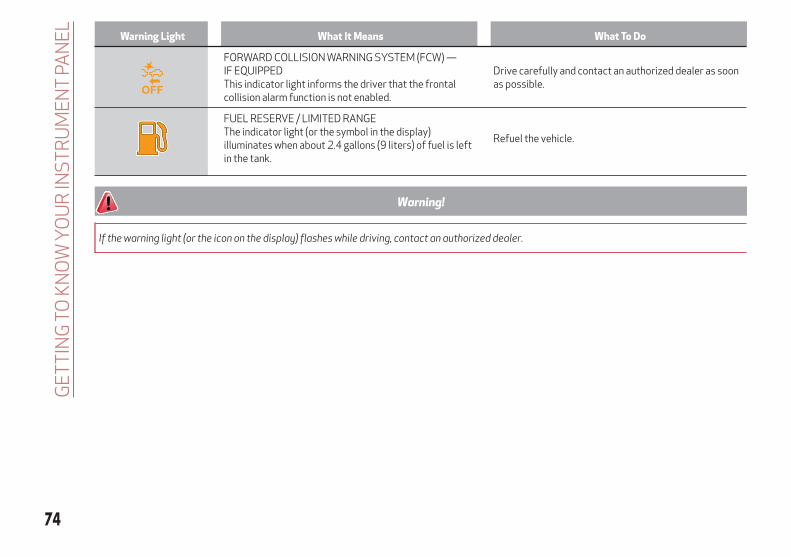
Warning Light What It Means What To Do
FORWARD COLLISION WARNING SYSTEM (FCW) —IF EQUIPPEDThis indicator light informs the driver that the frontalcollision alarm function is not enabled.
Drive carefully and contact an authorized dealer as soonas possible.
FUEL RESERVE / LIMITED RANGEThe indicator light (or the symbol in the display)illuminates when about 2.4 gallons (9 liters) of fuel is leftin the tank.
Refuel the vehicle.
Warning!
If the warning light (or the icon on the display) flashes while driving, contact an authorized dealer.
74
GE
TT
ING
TOK
NO
WY
OU
RIN
ST
RU
ME
NT
PAN
EL

Green Telltale Indicator Lights
Indicator light What It Means What To Do
PARK/HEADLIGHT ON INDICATOR LIGHTThis indicator will illuminate when the park lights orheadlights are turned on.
Headlight Off DelayThis function allows the headlights to remain on for 30,60 or 90 seconds after the ignition was placed in theSTOP position.
LEFT TURN SIGNALThe instrument cluster directional arrow will flashindependently for the left turn signal as selected, as wellas the exterior turn signal lamp(s) (front and rear) asselected when the multifunction lever is moved down(left). This directional arrow will flash in conjunction withthe right directional arrow when the hazard warning lightbutton is pushed.
RIGHT TURN SIGNALThe instrument cluster directional arrow will flashindependently for the right turn signal as selected, as wellas the exterior turn signal lamp(s) (front and rear) asselected when the multifunction lever is moved up (right).This directional arrow will flash in conjunction with the leftdirectional arrow when the hazard warning light button ispushed.
AUTOMATIC HIGH BEAM HEADLIGHTS(On Base Instrument Cluster Display)This indicator light will illuminate when the automatic highbeam headlights are activated.
75

Blue Telltale Indicator Light
Indicator Light What It Means What To Do
HIGH BEAM HEADLIGHTS(On Base Instrument Cluster Display)This indicator shows that the high beam headlights are on.Push the multifunction control lever away from you toswitch the headlights to high beam. Push the lever asecond time to switch the headlights back to low beam.Pull the lever toward you for a temporary high beam on,“flash to pass” scenario.
76
GE
TT
ING
TOK
NO
WY
OU
RIN
ST
RU
ME
NT
PAN
EL

Red Symbols
Symbol What It Means What To Do
LOW ENGINE OIL PRESSUREThis telltale indicates low engine oil pressure. If thetelltale turns on while driving, stop the vehicle and shutoff the engine as soon as possible. A chime will soundwhen this telltale turns on. Do not operate the vehicleuntil the cause is corrected. This telltale does not indicatehow much oil is in the engine. The engine oil level must bechecked under the hood.
Note:Do not use the vehicle until the failure has been solved.The turning on of the telltale does not indicate theamount of oil in the engine: the oil level can be checked onthe display upon entering the vehicle and also byactivating the "Oil level" function on the Information andEntertainment System.
Contact an authorized dealer as soon as possible.
Caution!
If the LOW ENGINE OIL PRESSURE symbol switches on when driving, stop the engine immediately and contact an authorized dealer.
77

Symbol What It Means What To Do
ENGINE COOLANT TEMPERATURE TOO HIGHThe telltale lights up when the engine has overheated.
In normal driving conditions: stop the car, turn off theengine and check that the coolant level in the reservoir isnot below the MIN mark. In this case, wait for the engineto cool down, then slowly and carefully open the cap, fillwith coolant and check that the level is between the MINand MAX marks on the reservoir itself. Also check visuallyfor any fluid leaks. Contact an authorized dealer if thetelltale comes on when the engine is started again.If the vehicle is used under demanding conditions (e.g. inhigh-performance driving): slow down and, if the warninglight stays on, stop the vehicle. Stop for 2 or 3 minuteswith the engine running and slightly accelerated tofacilitate better coolant circulation, then turn the engineoff. Check that the coolant level is correct as describedabove.
POWER STEERING FAILUREIf the telltale remains on, you could not have steeringassistance and the effort required to operate the steeringwheel could be increased; steering is, however, possible.
Note:
After the battery is disconnected, the steering wheel mustbe initialized. The Power Steering Failure light on theinstrument panel will illuminate to indicate this. To carryout this procedure, simply turn the steering wheel all theway from one end to the other, and then turn in back to thecentral position.
Contact an authorized dealer as soon as possible.
DOOR OPENThe telltale turns on when one or more doors are notcompletely shut. An acoustic signal is activated with thedoors open and the car moving.
Close the doors properly.
78
GE
TT
ING
TOK
NO
WY
OU
RIN
ST
RU
ME
NT
PAN
EL

Symbol What It Means What To Do
HOOD CAP NOT PROPERLY SHUTThe telltale turns on when the hood cap is not properlyclosed, along with the icon, an image of the vehicle with anopen hood cap appears on the display.A buzzer is heard when the hood cap is open and thevehicle is moving.
Close the hood properly.
TRUNK LID NOT PROPERLY SHUTThe telltale turns on when the trunk lid is not properlyclosed, along with the icon, an image of the vehicle with anopen trunk lid appears on the display.A buzzer is heard when the trunk lid is open and thevehicle is moving.
Close the trunk lid properly.
AUTOMATIC TRANSMISSION FAILUREThe telltale turns on, together with a buzzer warning, toindicate that the automatic transmission is faulty.
Contact an authorized dealer as soon as possible.
Caution!Driving the vehicle with this symbol on may severelydamage the gearbox, with resulting breakage. The oilmay also overheat: contact with hot engine or withexhaust components at high temperature could causefires.
79

Symbol What It Means What To Do
ELECTRONIC THROTTLE CONTROL (ETC) WARNINGLIGHTSThis warning light, along with the related message, signalsa failure in the electronic throttle control system (ETC).
Contact an authorized dealer as soon as possible.
If a failure is detected, the warning light turns on while theengine is running.
Place the gear selector in the P (Park) position and theignition in the off position: the warning light should switchoff. If the warning light stays on with engine running, thevehicle can still be driven.Contact an authorized dealer as soon as possible to havethe failure eliminated.
If the warning light flashes with the engine running,immediate intervention is required. A loss ofperformance, irregular/high idling speed or enginestopping might take place and the vehicle may need to betowed.
Contact an authorized dealer as soon as possible to havethe failure eliminated.
INSUFFICIENT ENGINE OIL LEVELThe telltale turns on, along with the related message onthe display, to indicate low engine oil level.
Contact an authorized dealer to have the system checked.
ALFA STEERING TORQUE (AST) FAILUREThe switching on of the telltale signals a failure in theautomatic steering correction system.
Contact an authorized dealer to have the system checked.
ALTERNATOR FAILUREThe switching on of the telltale with engine oncorresponds to an alternator failure.
Contact an authorized dealer as soon as possible.
80
GE
TT
ING
TOK
NO
WY
OU
RIN
ST
RU
ME
NT
PAN
EL

Amber Symbols
Symbol What It Means What To Do
ENGINE IMMOBILIZER FAILURE / BREAK-IN ATTEMPT
Engine Immobilizer System FailureThe telltale will illuminate to report a failure of the EngineImmobilizer system.
Contact an authorized dealer as soon as possible.
Break-In AttemptThe telltale will illuminate when the ignition is cycled toON position, to indicate a possible break-in attemptdetected by the alarm system.
Electronic Key Not RecognizedThe telltale will illuminate when the engine is started andthe electronic key is not recognized by the system.
Alarm System FailureThe telltale will illuminate to report an alarm systemfailure.
FUEL CUT-OFF INDICATOR LIGHTThe telltale will illuminate after an accident has occurredand the system has shut the fuel off.
For reactivating the fuel cut-off system, refer to“Enhanced Accident Response System” in “OccupantRestraint Systems" in "Safety” for further information. If itis not possible to restore the fuel supply, contact anauthorized dealer.
PARK SENSORS SYSTEM FAILUREThe telltale will illuminate when the system has failed or isnot available.
Contact an authorized dealer to have the system checked.
81

Symbol What It Means What To Do
POSSIBLE ICE ON ROADThe telltale will illuminate when the outside temperaturefalls to or below 37°F (3°C).
ENGINE OIL CHANGE REQUIRED — IF EQUIPPEDThe telltale is illuminated only for a limited time.
Note:After the first indication, each time the engine is startedthe symbol will continue to illuminate as described aboveuntil the oil is changed.If the telltale flashes, this does not mean that there is afault on the vehicle, rather it simply reports that it is nownecessary to change the oil as a result of regular use ofthe vehicle. The deterioration of engine oil is acceleratedby using the vehicle for short drives, preventing theengine from reaching operating temperature.
Contact an authorized dealer as soon as possible.
Caution!
Deteriorated engine oil should be replaced as soon as possible after the symbol is switched on, and never more than 500 miles (805 km) after itfirst switches on. Failure to observe the above may result in severe damage to the engine and invalidate the New Vehicle Limited Warranty. Whenthis symbol comes on, it does not mean that the level of engine oil is low, so if it flashes you do not need to top up the engine oil.
82
GE
TT
ING
TOK
NO
WY
OU
RIN
ST
RU
ME
NT
PAN
EL

Symbol What It Means What To Do
ENGINE OIL PRESSURE SENSOR FAILUREThe telltale will illuminate in the event of engine oilpressure sensor failure.
Contact an authorized dealer as soon as possible.
ENGINE OIL LEVEL SENSOR FAILUREThe telltale will illuminate in the event of engine oil levelsensor failure.
Contact an authorized dealer as soon as possible.
FORWARD COLLISION WARNING (FCW) SYSTEMFAILUREThe telltale will illuminate in the case of failure of theForward Collision Warning system.
Contact an authorized dealer as soon as possible.
START/STOP SYSTEM FAILUREThis telltale will illuminate to report a Stop/Start systemfailure.
Contact an authorized dealer as soon as possible to havethe failure eliminated.
RAIN SENSOR FAILUREThe telltale will illuminate in the case of failure of theautomatic windshield wiper.
Contact an authorized dealer as soon as possible.
DUSK SENSOR FAILUREThe telltale will illuminate in the case of failure of theautomatic low beam alignment.
Contact an authorized dealer as soon as possible.
BLIND SPOT MONITORING SYSTEM FAILUREThe telltale will illuminate in the event of a Blind SpotMonitoring system failure.
Contact an authorized dealer as soon as possible.
83

Symbol What It Means What To Do
FUEL LEVEL SENSOR FAILUREThe telltale will illuminate in the event of fuel level sensorfailure.
Contact an authorized dealer as soon as possible.
EXTERIOR LIGHTS FAILUREThe telltale will illuminate to indicate a failure on thefollowing lights: daytime running lights (DRLs) / parkinglights / trailer turn signal indicators (if present) / trailerlights (if present) / side lights / turn signal indicators /rear fog light / reversing light / brake lights / license platelights.
The failure may be caused by a blown bulb, a blownprotection fuse, or an interruption of the electricalconnection.Replace the bulb or the relevant fuse. Contact anauthorized dealer.
KEYLESS SYSTEM FAILUREThe telltale will illuminate in the event of keyless systemfailure.
Contact an authorized dealer as soon as possible.
FUEL CUT-OFF SYSTEM FAILUREThe telltale will illuminate in the event of fuel cut-offsystem failure.
Contact an authorized dealer as soon as possible.
LANE DEPARTURE WARNING (LDW) SYSTEM FAILUREThe telltale will illuminate in the event of a fault in theLane Departure Warning system.
Contact an authorized dealer as soon as possible.
AUTOMATIC HIGH BEAM HEADLIGHTS FAILURE —IF EQUIPPEDThe telltale will illuminate to report a failure of theautomatic high beam headlights.
Contact an authorized dealer as soon as possible to havethe failure eliminated.
84
GE
TT
ING
TOK
NO
WY
OU
RIN
ST
RU
ME
NT
PAN
EL
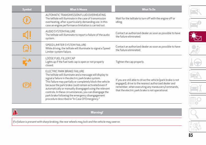
Symbol What It Means What To Do
AUTOMATIC TRANSMISSION FLUID OVERHEATINGThe telltale will illuminate in the case of transmissionoverheating, after a particularly demanding use. In thiscase an engine performance limitation is carried out.
Wait for the telltale to turn off with the engine off oridling.
AUDIO SYSTEM FAILUREThe telltale will illuminate to report a failure of the audiosystem.
Contact an authorized dealer as soon as possible to havethe failure eliminated.
SPEED LIMITER SYSTEM FAILUREWhile driving, the telltale will illuminate to signal a SpeedLimiter system failure.
Contact an authorized dealer as soon as possible to havethe failure eliminated.
LOOSE FUEL FILLER CAPLights up if the fuel tank cap is open or not properlyclosed.
Tighten the cap properly.
ELECTRIC PARK BRAKE FAILUREThe telltale will illuminate and a message will display tosignal a failure in the electric park brake system.This failure may partially or completely block the vehiclebecause the park brake could remain activated even ifautomatically or manually disengaged using the relevantcontrols. In these circumstances, you can disengage thepark brake following the emergency disengagementprocedure described in “In Case Of Emergency.”
If you are still able to drive the vehicle (park brake is notengaged), drive to the nearest authorized dealer andremember, when executing any maneuvers/commands,that the electric park brake is not operational.
Warning!
If a failure is present with sharp braking, the rear wheels may lock and the vehicle may swerve.
85
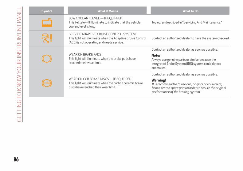
Symbol What It Means What To Do
LOW COOLANT LEVEL — IF EQUIPPEDThis telltale will illuminate to indicate that the vehiclecoolant level is low.
Top up, as described in "Servicing And Maintenance.”
SERVICE ADAPTIVE CRUISE CONTROL SYSTEMThis light will illuminate when the Adaptive Cruise Control(ACC) is not operating and needs service.
Contact an authorized dealer to have the system checked.
WEAR ON BRAKE PADSThis light will illuminate when the brake pads havereached their wear limit.
Contact an authorized dealer as soon as possible.
Note:Always use genuine parts or similar because theIntegrated Brake System (IBS) system could detectanomalies.
WEAR ON CCB BRAKE DISCS — IF EQUIPPEDThis light will illuminate when the carbon ceramic brakediscs have reached their wear limit.
Contact an authorized dealer as soon as possible.
Warning!It is recommended to use only original or equivalent,bench-tested spare pads in order to ensure the originalperformance of the braking system.
86
GE
TT
ING
TOK
NO
WY
OU
RIN
ST
RU
ME
NT
PAN
EL

Symbol What It Means What To Do
DYNAMIC DRIVE CONTROL SYSTEM FAILUREThe telltale will illuminate to signal a failure in thedynamic drive control system.
WINDSHIELD WIPER FAILURESignals a windshield wiper failure.
Contact an authorized dealer.
GENERIC INDICATIONSignals information and failures.The accompanying messages describe the failure.
FOUR WHEEL DRIVE FAILUREThis telltale will illuminate to report a four wheel drivesystem failure.
Contact an authorized dealer as soon as possible to havethe failure eliminated.
AFS SYSTEM FAILUREThe telltale will illuminate to indicate the automaticdirectional light system failure.
Go to an authorized dealer to have the system checked.
SOFT SUSPENSION CALIBRATION INSERTION —IF EQUIPPEDThe telltale will illuminate when the most comfortablesuspension setting is activated.
SHOCK ABSORBERS FAILURE (ADC) — IF EQUIPPEDWhile driving, if the telltale illuminates, it signals a failurein the suspension system.
Contact an authorized dealer to have the system checked.
WINDSHIELD WASHER LIQUID LEVELThe telltale will illuminate to indicate that the level of thewindshield and headlight washing fluid (if any) is low.
To refill the liquid, refer to “Engine Compartment” in“Servicing And Maintenance.” Always use liquid with thefeatures indicated in the “Fluids And Lubricants” sectionin “Technical Specifications.”
87

Green Symbols
Symbol What It Means
HEADLIGHTSThe telltale will illuminate when the headlights are turned on.
AUTOMATIC HEADLIGHTSThe symbol lights up when the automatic headlights are on.
START/STOP OPERATIONThe telltale will illuminate in the case of Start/Stop system intervention (stopping the engine).When the engine is restarted, the telltale will shut off (for the engine restarting modes refer to “Stop/Start” in “Starting AndOperating”).
SPEED CONTROL ACTIVATEDThe telltale will illuminate when the Speed Control system is activated.
ADAPTIVE CRUISE CONTROL SYSTEMThe symbol comes on when the Adaptive Cruise Control system is activated.
Blue Symbols
Symbol What it means
AUTOMATIC HIGH BEAM HEADLIGHTSThe telltale will illuminate when the automatic high beam headlights are activated.
HIGH BEAM HEADLIGHTSThe telltale will illuminate when the high beam headlights are activated.
88
GE
TT
ING
TOK
NO
WY
OU
RIN
ST
RU
ME
NT
PAN
EL

ONBOARD DIAGNOSTICSYSTEMOperation
The OBD (Onboard Diagnostic system)carries out a continuous diagnosis of thecomponents of the vehicle related toemissions.It also alerts the driver of when thesecomponents are no longer in peakcondition by switching on the warninglight on the instrument panel (see“Warning Lights And Messages”paragraph in this chapter).The aim of the OBD system (OnboardDiagnostic) is to:
Monitor the efficiency of the system
Indicate an increase in emissions
Indicate the need to replace damagedcomponents
The vehicle also has a connector, whichcan interface with appropriate tools, thatmakes it possible to read the error codesstored in the electronic control unitstogether with a series of specificparameters for engine operation anddiagnosis. This check can be carried outby your authorized dealer.Note: After eliminating a fault, to checkthe system completely, your authorizeddealer is obliged to run tests and, ifnecessary certain road tests.
Onboard Diagnostic System (OBD II)CybersecurityYour vehicle is required to have anOnboard Diagnostic system (OBD II) anda connection port to allow access toinformation related to the performanceof your emissions controls. Authorizedservice technicians may need to accessthis information to assist with thediagnosis and service of your vehicle andemissions system.
Warning!
ONLY an authorized service technicianshould connect equipment to the OBD IIconnection port in order to diagnose orservice your vehicle.
If unauthorized equipment is connected tothe OBD II connection port, such as adriver-behavior tracking device, it may:
Be possible that vehicle systems,including safety related systems, could beimpaired or a loss of vehicle control couldoccur that may result in an accidentinvolving serious injury or death.
Access, or allow others to access,information stored in your vehicle systems,including personal information.
89

90
This page is intentionally left blank
SAFETY
This very important section describesthe safety systems that your vehicle maybe equipped with, and providesinstructions on how to use themcorrectly.
ACTIVE SAFETY SYSTEMS . . . . . . .92AUXILIARY DRIVING SYSTEMS . . . .95OCCUPANT RESTRAINT SYSTEMS . .104SAFETY TIPS . . . . . . . . . . . . . .128
91
ACTIVE SAFETY SYSTEMSThe vehicle may be equipped with thefollowing active safety devices:
Anti-Lock Braking (ABS) System
Drive Train Control (DTC) System
Electronic Stability Control (ESC)System
Traction Control System (TCS)
Panic Brake Assist (PBA) System
Hill Start Assist (HSA) System
Dynamic Steering Torque (DST)System
For the operation of the systems, see thefollowing pages.
Anti-Lock Braking (ABS) SystemAn integral part of the braking system,the ABS prevents one or more wheelsfrom locking and slipping in all roadsurface conditions, regardless of theintensity of the braking action. Thesystem ensures that the vehicle can becontrolled even during emergencybraking, allowing the driver to optimizestopping distances.The system intervenes during brakingwhen the wheels are about to lock,typically in emergency braking orlow-grip conditions where locking may bemore frequent.The system also improves control andstability of the vehicle when braking on asurface where the grip of the left andright wheels varies, such as in a corner.
The Electronic Braking Force Distribution(EBD) system works with the ABS,allowing the brake force to be distributedbetween the front and rear wheels.
System Intervention
The ABS equipped on this vehicle isprovided with the "Brake-by-wire"(Integrated Brake System - IBS) function.With this system, the command given bypressing the brake pedal is nottransmitted hydraulically, but electrically.Therefore, the light pulsation that is felton the pedal with the traditional systemis no longer noticeable.
Warning!
The ABS contains sophisticatedelectronic equipment that may besusceptible to interference caused byimproperly installed or high output radiotransmitting equipment. This interferencecan cause possible loss of anti-lock brakingcapability. Installation of such equipmentshould be performed by qualifiedprofessionals.
Pumping of the Anti-Lock Brakes willdiminish their effectiveness and may lead toa collision. Pumping makes the stoppingdistance longer. Just press firmly on yourbrake pedal when you need to slow down orstop.
The ABS cannot prevent the natural lawsof physics from acting on the vehicle, norcan it increase braking or steering efficiency
beyond that afforded by the condition of thevehicle brakes and tires or the tractionafforded.
The ABS cannot prevent collisions,including those resulting from excessivespeed in turns, following another vehicle tooclosely, or hydroplaning.
The capabilities of an ABS equippedvehicle must never be exploited in a recklessor dangerous manner that could jeopardizethe user’s safety or the safety of others.
Drive Train Control (DTC) System —If EquippedSome models of this vehicle are equippedwith an All-Wheel Drive system (AWD),which offers an optimal drive forcountless driving conditions and roadsurfaces. The system reduces theslipping of the tires to a minimum,automatically redistributing the torqueto the front and rear wheels as needed.To maximize fuel savings, the vehicle withAWD automatically passes to rear-wheeldrive (RWD) when the road andenvironmental conditions are such thatthey wouldn't cause the tires to slip.When the road and environmentalconditions require better traction, thevehicle automatically goes to AWD mode.The driving mode, RWD or AWD, is shownon the instrument cluster display.Note: If the system failure symbolswitches on, after starting the engine orwhile driving, it means that the AWDsystem is not working properly. If the92
SA
FE
TY

warning message activates frequently, itis recommended to carry out themaintenance operations.
Electronic Stability Control (ESC)SystemThe ESC system improves the directionalcontrol and stability of the vehicle invarious driving conditions.The ESC system corrects the vehicle’sundersteer and oversteer, distributingthe brake force on the appropriatewheels. The torque supplied by theengine can also be reduced in order tomaintain control of the vehicle.The ESC system uses sensors installedon the vehicle to determine the path thatthe driver intends to follow andcompares it with the vehicle’s effectivepath. When the real path deviates fromthe desired path, the ESC systemintervenes to counter the vehicle’sundersteer or oversteer.
Oversteer occurs when the vehicle isturning more than it should according tothe angle of the steering wheel.
Understeer occurs when the vehicle isturning less than it should according tothe angle of the steering wheel.
System Intervention
The intervention of the system isindicated by the flashing of the ESCwarning light on the instrument panel, toinform the driver that the vehiclestability and grip are critical.
Warning!
Electronic Stability Control (ESC) cannotprevent the natural laws of physics fromacting on the vehicle, nor can it increase thetraction afforded by prevailing roadconditions. ESC cannot prevent accidents,including those resulting from excessivespeed in turns, driving on very slipperysurfaces, or hydroplaning. ESC also cannotprevent accidents resulting from loss ofvehicle control due to inappropriate driverinput for the conditions. Only a safe,attentive, and skillful driver can preventaccidents. The capabilities of an ESCequipped vehicle must never be exploited ina reckless or dangerous manner which couldjeopardize the user’s safety or the safety ofothers.
Vehicle modifications, or failure toproperly maintain your vehicle, may changethe handling characteristics of your vehicle,and may negatively affect the performanceof the ESC system. Changes to the steeringsystem, suspension, braking system, tiretype and size or wheel size may adverselyaffect ESC performance. Improperlyinflated and unevenly worn tires may alsodegrade ESC performance. Any vehiclemodification or poor vehicle maintenancethat reduces the effectiveness of the ESCsystem can increase the risk of loss ofvehicle control, vehicle rollover, personalinjury and death.
Traction Control System (TCS)The system automatically operates in theevent of slipping, loss of grip on wetroads (hydroplaning), and acceleration onone or both drive wheels on roads thatare slippery, snowy, icy, etc. Dependingon the slipping conditions, two differentcontrol systems are activated:
If the slipping involves both drivewheels, the system intervenes, reducingthe power transmitted by the engine.
If the slipping only involves one of thedrive wheels, the Brake LimitedDifferential (BLD) function is activated,automatically braking the wheel which isslipping (the behavior of a self-lockingdifferential is simulated). This willincrease the engine torque transferred tothe wheel which isn't slipping.
System Intervention
The intervention of the system isindicated by the flashing of the ESCwarning light on the instrument panel, toinform the driver that the vehiclestability and grip are critical.
Panic Brake Assist (PBA) SystemThe PBA system is designed to improvethe vehicle’s braking capacity duringemergency braking.The system detects emergency brakingby monitoring the speed and force withwhich the brake pedal is pressed, andconsequently applies the optimal brakepressure. This can reduce the braking 93

distance: the PBA system thereforecomplements the ABS.Maximum assistance from the PBAsystem is obtained by pressing the brakepedal very quickly. In addition, the brakepedal should be pressed continuouslyduring braking, avoiding intermittentpresses, to get the most out of thesystem. Do not reduce pressure on thebrake pedal until braking is no longernecessary.The PBA system is deactivated when thebrake pedal is released.
Warning!
The Panic Brake Assist (PBA) cannot preventthe natural laws of physics from acting onthe vehicle, nor can it increase the tractionafforded by prevailing road conditions. PBAcannot prevent collisions, including thoseresulting from excessive speed in turns,driving on very slippery surfaces, orhydroplaning. The capabilities of aPBA-equipped vehicle must never beexploited in a reckless or dangerous manner,which could jeopardize the user's safety orthe safety of others.
Hill Start Assist (HSA) SystemThis is an integral part of the ESC systemand facilitates starting on slopes,activating automatically in the followingcases:
Uphill: vehicle stationary on a roadwith a gradient higher than 5%, engine
running, brake pressed and transmissionin NEUTRAL (N) or gear other thanREVERSE (R) engaged.
Downhill: vehicle stationary on a roadwith a gradient higher than 5%, enginerunning, brake pressed and reverse gearengaged.
When setting off, the ESC system controlunit maintains the braking pressure onthe wheels until the engine torquenecessary for starting is reached, or inany case for a maximum of two seconds,allowing your right foot to be movedeasily from the brake pedal to theaccelerator.The system will automatically deactivateafter two seconds without starting,gradually releasing the braking pressure.During this release stage, it is possible tohear a typical mechanical brake releasenoise, indicating the imminent movementof the vehicle.
Warning!
There may be situations where the Hill StartAssist (HSA) will not activate and slightrolling may occur, such as on minor hills orwith a loaded vehicle, or while pulling atrailer. HSA is not a substitute for activedriving involvement. It is always the driver’sresponsibility to be attentive to distance toother vehicles, people, and objects, and mostimportantly brake operation to ensure safeoperation of the vehicle under all roadconditions. Your complete attention is
always required while driving to maintainsafe control of your vehicle. Failure to followthese warnings can result in a collision orserious personal injury.
Dynamic Steering Torque (DST) SystemThe DST function uses the integration ofthe ESC system with the electric powersteering to increase the safety level ofthe whole vehicle.In critical situations (braking on surfaceswith different grip conditions), the ESCsystem controls the steering through theDST function to implement an additionaltorque contribution on the steering wheelin order to suggest the most correctmaneuver to the driver.The coordinated action of the brakes andsteering increases the sensation ofsafety and control of the vehicle.Note: The DST feature is only meant tohelp the driver realize the correct courseof action through small torques on thesteering wheel, which means theeffectiveness of the DST feature is highlydependent on the driver’s sensitivity andoverall reaction to the applied torque. Itis very important to realize that thisfeature will not steer the vehicle,meaning the driver is still responsible forsteering the vehicle.
94
SA
FE
TY

AUXILIARY DRIVING SYSTEMSThe following auxiliary driving systemsare available in this vehicle:
Blind Spot Monitoring (BSM)
Forward Collision Warning (FCW)
Tire Pressure Monitoring System(TPMS)
Blind Spot Monitoring (BSM) SystemThe Blind Spot Monitoring (BSM) systemuses two radar sensors, located in therear bumper (one for each side), to detectthe presence of other vehicles in the rearside blind spots of your vehicle.
The system warns the driver about thepresence of other vehicles in thedetection area by illuminating thewarning light located within the doormirror on the side in which the othervehicle was detected.
When the engine is started the warninglight turns on to signal the driver that thesystem is active.
Sensors
The sensors are activated when anyforward gear is engaged at a speedhigher than approximately 6 mph(10 km/h) or when REVERSE is engaged.The sensors are temporarily deactivatedwhen the vehicle is stationary and inPARK (P).The detection area of the system coversapproximately a lane on both sides of thevehicle which is around 9 ft (3 m).This area begins from the door mirror andextends for approximately 19 ft (6 m)towards the rear part of the vehicle.When the sensors are active, the systemmonitors the detection areas on bothsides of the vehicle and warns the driverabout the possible presence of vehiclesin these areas.
While driving, the system monitors thedetection area from three different inputpoints (side, rear and front) to checkwhether an alert needs to be sent to thedriver. The system can detect thepresence of a vehicle in one of thesethree areas.
Note:
The system does not alert the driverfor the presence of fixed object (e.g.safety barriers, poles, walls, etc.).However, in some circumstances, thesystem may activate in the presence ofthese objects. This is normal and doesnot indicate a system malfunction.
The system does not alert the driverabout the presence of vehicles comingfrom the opposite direction, in theadjacent lanes.
Warning!
The Blind Spot Monitoring system is only anaid to help detect objects in the blind spotzones. The BSM system is not designed todetect pedestrians, bicyclists, or animals.Even if your vehicle is equipped with theBSM system, always check your vehicle’smirrors, glance over your shoulder, and useyour turn signal before changing lanes.Failure to do so can result in serious injury ordeath.
06016S0001EM
Rear Sensor Location
06016S0002EM
BSM Indicator Light
95

Note:
For the system to operate correctly,the rear bumper area where the radarsensors are located must stay free fromsnow, ice and dirt gathered from theroad surface.
Do not cover the rear bumper areawhere the radar sensors are located withany object (e.g. adhesives, bike rack,etc.).
If you wish to install the tow hookafter purchasing the vehicle, you need todeactivate the system via theInformation and Entertainment System.To access the function, select thefollowing items in sequence on the mainmenu:
1. “Settings.”
2. “Safety.”
3. “Blind Spot Alert.”
Rear View
The system detects vehicles coming fromthe rear part of your vehicle on both sidesand entering the rear detection area witha difference in speed of less than 31 mph(50 km/h) with relation to your vehicle.
Overtaking Vehicles
If another vehicle is overtaken slowly,with a difference in speed of less thanapproximately 15 mph (25 km/h) and thevehicle stays in the blind spot forapproximately 1.5 seconds, the warninglight on the door mirror of thecorresponding side illuminates.If the difference in speed between thetwo vehicles is greater thanapproximately 15 mph (25 km/h), thewarning light does not illuminate.
Rear Cross Path Detection (RCP)System
This system helps the driver duringreverse maneuvers in the case of reducedvisibility.The RCP system monitors the reardetection areas on both sides of thevehicle to detect objects moving towardsthe sides of the vehicle, with a minimumspeed between approximately 1 mph(1 km/h) and 2 mph (3 km/h) and objectsmoving at a maximum speed of 21 mph(35 km/h), in areas such as parking lots.The system activation is signaled to thedriver by an acoustic warning.Note: If the sensors are covered byobjects or vehicles, the system will notwarn the driver.
Warning!
Rear Cross Path Detection (RCP) is not aback up aid system. It is intended to be usedto help a driver detect an oncoming vehicle ina parking lot situation. Drivers must becareful when backing up, even when usingRCP. Always check carefully behind yourvehicle, look behind you, and be sure to checkfor pedestrians, animals, other vehicles,obstructions, and blind spots before backingup. Failure to do so can result in seriousinjury or death.
Operating Mode
The system may be activated/deactivated via the Information andEntertainment System. To access thefunction, select the following items onthe main menu in sequence:
1. “Settings.”
2. “Safety.”
3. “Blind Spot Alert.”
"Blind Spot Alert,” "Visual" Mode
When the system is enabled, the warninglight within the door mirror on the side ofthe detected object illuminates.The visual warning on the mirror will blinkif the driver activates the turn signals,thus indicating the intention to changelane.
96
SA
FE
TY
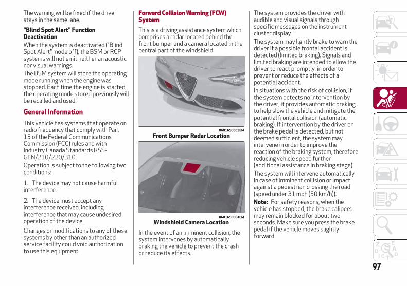
The warning will be fixed if the driverstays in the same lane.
"Blind Spot Alert" FunctionDeactivation
When the system is deactivated ("BlindSpot Alert" mode off), the BSM or RCPsystems will not emit neither an acousticnor visual warnings.The BSM system will store the operatingmode running when the engine wasstopped. Each time the engine is started,the operating mode stored previously willbe recalled and used.
General Information
This vehicle has systems that operate onradio frequency that comply with Part15 of the Federal CommunicationsCommission (FCC) rules and withIndustry Canada Standards RSS-GEN/210/220/310.Operation is subject to the following twoconditions:
1. The device may not cause harmfulinterference.
2. The device must accept anyinterference received, includinginterference that may cause undesiredoperation of the device.
Changes or modifications to any of thesesystems by other than an authorizedservice facility could void authorizationto use this equipment.
Forward Collision Warning (FCW)SystemThis is a driving assistance system whichcomprises a radar located behind thefront bumper and a camera located in thecentral part of the windshield.
In the event of an imminent collision, thesystem intervenes by automaticallybraking the vehicle to prevent the crashor reduce its effects.
The system provides the driver withaudible and visual signals throughspecific messages on the instrumentcluster display.The system may lightly brake to warn thedriver if a possible frontal accident isdetected (limited braking). Signals andlimited braking are intended to allow thedriver to react promptly, in order toprevent or reduce the effects of apotential accident.In situations with the risk of collision, ifthe system detects no intervention bythe driver, it provides automatic brakingto help slow the vehicle and mitigate thepotential frontal collision (automaticbraking). If intervention by the driver onthe brake pedal is detected, but notdeemed sufficient, the system mayintervene in order to improve thereaction of the braking system, thereforereducing vehicle speed further(additional assistance in braking stage).The system will intervene automaticallyin case of imminent collision or impactagainst a pedestrian crossing the road(speed under 31 mph (50 km/h)).Note: For safety reasons, when thevehicle has stopped, the brake calipersmay remain blocked for about twoseconds. Make sure you press the brakepedal if the vehicle moves slightlyforward.
06016S0003EM
Front Bumper Radar Location
06016S0004EM
Windshield Camera Location
97

Warning!
Forward Collision Warning (FCW) is notintended to avoid a collision on its own, norcan FCW detect every type of potentialcollision. The driver has the responsibility toavoid a collision by controlling the vehicle viabraking and steering. Failure to follow thiswarning could lead to serious injury or death.
Engagement/Disengagement
The following functions can be selectedin sequence using the Information andEntertainment System:
1. “Settings.”
2. “Safety.”
3. “Forward Collision Warning.”
4. “Mode.”
Select from among three operatingmodes:
Warning And Brake: the system (ifactive), in addition to the visual andaudible warnings, provides limitedbraking, automatic braking and additionalassistance in braking stage, where thedriver does not brake sufficiently in theevent of a potential frontal impact.
Only Warning: the system (if active),does not provide limited braking, butguarantees automatic braking oradditional assistance in braking stage,
where the driver does not brake at all ornot sufficiently in the event of a potentialfrontal impact.
Disable: the system does not providevisual and audible warnings, limitedbraking, automatic braking or additionalassistance in braking stage. The systemwill therefore provide no indication of apossible accident.
Activation/Deactivation
The Forward Collision Warning system isactivated whenever the engine is startedregardless of what is shown on theInformation and Entertainment System.Following a deactivation, the system willnot warn the driver about the possiblecollision with the preceding vehicle,regardless of the setting selected withthe Information and EntertainmentSystem.Note: Each time the engine is started,the system is activated regardless ofwhat setting was selected when theengine was turned OFFThis function is not active at a speedlower than 4 mph (7 km/h) or higher than124 mph (200 km/h).The system is active:
Each time the engine is started.
In the Information and EntertainmentSystem.
When the ignition is in the ON position.
The vehicle speed is between 4 mph(7 km/h) and 124 mph (200 km/h).
When the front seat belts arefastened.
Changing The System Sensitivity
The sensitivity of the system can bechanged through the Information andEntertainment System menu, choosingfrom one of the following three options:"Near", "Med" or "Far". Refer to thedescription in the “Information andEntertainment System Supplement” forhow to change the settings.The default setting is "Med". With thissetting, the system warns the driver of apossible collision with the vehicle in frontwhen that vehicle is at a standarddistance, between that of the other twosettings.With the system sensitivity set to "Far",the system will warn the driver of apossible collision with the vehicle in frontwhen that vehicle is at a greater distance,thus providing the possibility of acting onthe brakes more lightly and gradually.This setting provides the drivers with themaximum possible reaction time toprevent a potential accident.With the option set to "Near", the systemwill alert the driver of a possible collisionwith the vehicle in front when that vehicleis close. This setting offers the driver alower reaction time compared to the"Med" and "Far" settings, in the event of a
98
SA
FE
TY

potential collision, but permits moredynamic driving of the vehicle.The system sensitivity setting is kept inthe memory when the engine is turnedOFF.System Limited Operation Signal
If a dedicated message is displayed, acondition limiting the system operationmay have occurred. The possible reasonsof this limitation are something blockingthe camera view or a fault.If an obstruction is signaled, clean thearea of the windshield indicated in.Although the vehicle can still be driven innormal conditions, the system may be notcompletely available.When the conditions limiting the systemfunctions end, this will go back to normaland complete operation. Should the faultpersist, contact an authorized dealer.System Failure Signaling
If the system turns off and a dedicatedmessage is shown on the display, itmeans that there is a fault with thesystem.In this case, it is still possible to drive thevehicle, but you are advised to contact anauthorized dealer as soon as possible.Radar Indication Not Available
If conditions are such that the radarcannot detect obstacles correctly, thesystem is deactivated and a dedicatedmessage appears on the display. Thisgenerally occurs in the event of poor
visibility, such as when it is snowing orraining heavily.The function of this system can also betemporarily reduced due to obstructionssuch as mud, dirt or ice on the bumper. Insuch cases, a dedicated message will beshown on the display and the system willbe deactivated. This message cansometimes appear in conditions of highreflectivity (e.g. tunnels with reflectivetiles or ice or snow). When the conditionslimiting the system functions end, it willgo back to normal and completeoperation.In certain cases, this dedicated messagecould be displayed when the radar is notdetecting any vehicles or objects withinits view range.If atmospheric conditions are not thereason behind this message, check if thesensor is dirty. It could be necessary toclean or remove any obstructions in thearea.If the message appears frequently, evenin the absence of atmospheric conditionssuch as snow, rain, mud or otherobstructions, contact an authorizeddealer for a sensor alignment check.In the absence of visible obstructions,manually removing the decorative covertrim and cleaning the radar surface couldbe required. Have this operationperformed at an authorized dealer.Note: It is recommended that you do notinstall devices, accessories oraerodynamic attachments in front of the
sensor or darken it in any way, as this cancompromise the correct functioning ofthe system.Frontal Collision Alarm With ActiveBraking — If Equipped
If this function is selected, the brakes areoperated to reduce the speed of thevehicle in the event of potential frontalimpact.This function applies an additionalbraking pressure if the braking pressureapplied by the driver does not suffice toprevent potential frontal impact.The function is active with speed above4 mph (7 km/h).Driving In Special Conditions
In certain driving conditions, systemintervention might be unexpected ordelayed. The driver must therefore bevery careful, keeping control of thevehicle to drive in complete safety.
Driving close to a bend.
The vehicle ahead is leaving aroundabout.
Vehicles with small dimensions and/ornot aligned in the driving lane.
Lane change by other vehicles.
Vehicles traveling at right angles to thevehicle.
System intervention might beunexpected or delayed. The driver must
99
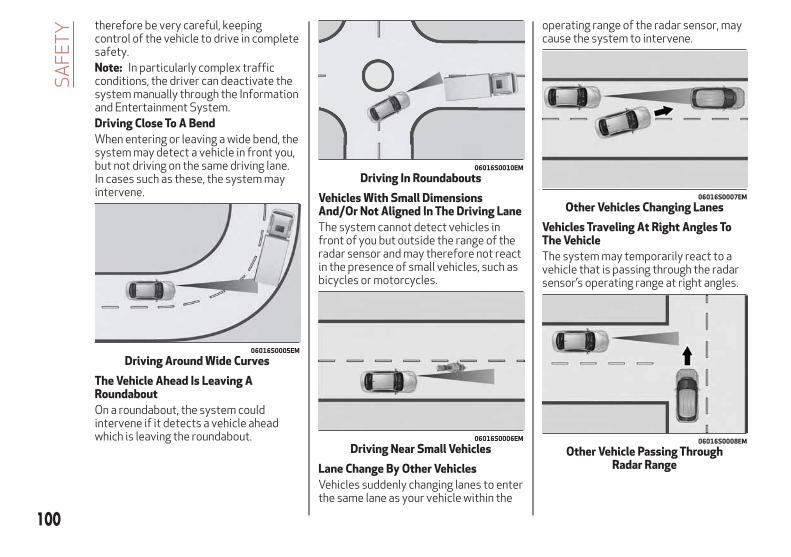
therefore be very careful, keepingcontrol of the vehicle to drive in completesafety.Note: In particularly complex trafficconditions, the driver can deactivate thesystem manually through the Informationand Entertainment System.Driving Close To A Bend
When entering or leaving a wide bend, thesystem may detect a vehicle in front you,but not driving on the same driving lane.In cases such as these, the system mayintervene.
The Vehicle Ahead Is Leaving ARoundabout
On a roundabout, the system couldintervene if it detects a vehicle aheadwhich is leaving the roundabout.
Vehicles With Small DimensionsAnd/Or Not Aligned In The Driving Lane
The system cannot detect vehicles infront of you but outside the range of theradar sensor and may therefore not reactin the presence of small vehicles, such asbicycles or motorcycles.
Lane Change By Other Vehicles
Vehicles suddenly changing lanes to enterthe same lane as your vehicle within the
operating range of the radar sensor, maycause the system to intervene.
Vehicles Traveling At Right Angles ToThe Vehicle
The system may temporarily react to avehicle that is passing through the radarsensor’s operating range at right angles.
06016S0005EM
Driving Around Wide Curves
06016S0010EM
Driving In Roundabouts
06016S0006EM
Driving Near Small Vehicles
06016S0007EM
Other Vehicles Changing Lanes
06016S0008EM
Other Vehicle Passing ThroughRadar Range
100
SA
FE
TY

Warning!
The system has not been designed toprevent impacts and cannot detect possibleconditions leading to an accident inadvance. Failure to take into account thiswarning may lead to serious or fatal injuries.
The system may activate, assessing thetrajectory of the vehicle, for the presence ofreflecting metal objects different fromother vehicles, such as safety barriers, roadsigns, barriers before parking lots, tollgates,level crossings, gates, railways, objects nearroad constructions sites or higher than thevehicle (e.g. a fly-over). In the same way, thesystem may intervene inside multi-storyparking lots or tunnels, or due to a glare onthe road surface. These possible activationsare a consequence of the real drivingscenario coverage by the system and mustnot be regarded as faults.
The system has been designed for roaduse only. If the vehicle is driven on a track,the system must be deactivated to avoidunnecessary warnings. Automaticdeactivation is signaled by the dedicatedwarning light/symbol switching on in theinstrument panel (refer to the instructions inthe "Warning Lights And Messages On TheInstrument Panel" in "Getting To Know YourInstrument Panel" for further information).
Tire Pressure Monitoring System(TPMS)This vehicle is equipped with a TirePressure Monitoring System (TPMS) thatsends the inflation pressure informationof each tire to the control unit, and willsignal the driver in the event ofinsufficient tire pressure.Tire pressure will vary with temperatureby approximately 1 psi (7 kPa) for every12°F (6.5°C). This means that when theoutside temperature decreases, the tirepressure will also decrease. Tire pressureshould always be set based on coldinflation tire pressure. This is defined asthe tire pressure after the vehicle has notbeen driven for at least three hours, ordriven less than 1 mile (1.6 km) after athree hour period. The cold tire inflationpressure must not exceed the maximuminflation pressure molded into the tiresidewall. Refer to “Tires” in “ServicingAnd Maintenance” for information onhow to properly inflate the vehicle’s tires.The tire pressure will also increase as thevehicle is driven. This is normal, and thereshould be no adjustment for thisincreased pressure.The TPMS will signal the driver ifpressure falls below the warning limit forany reason, including the effects of lowtemperature and normal loss of pressurefrom the tire.The TPMS will stop indicating insufficienttire pressure when pressure is equal to orgreater than the prescribed cold inflation
level. Therefore, if insufficient tirepressure is indicated by the ( ) warninglight displaying in the instrument cluster,increase the inflation pressure up to theprescribed cold inflation value.The system will automatically update,and the “Tire Pressure Monitoring TelltaleLight” will turn off once the systemreceives the updated tire pressures. Thevehicle may need to be driven for up to20 minutes above 15 mph (24 km/h) inorder for the TPMS to receive thisinformation.
Operating Example
For example, your vehicle may have arecommended cold (parked for more thanthree hours) placard pressure of 33 psi(227 kPa). If the ambient temperature is68°F (20°C), and the measured tirepressure is 28 psi (193 kPa), atemperature drop to 20°F (-7°C) willdecrease the tire pressure toapproximately 24 psi (165 kPa). This tirepressure is low enough to turn on the“Tire Pressure Monitoring Warning Light.”Driving the vehicle may cause the tirepressure to rise to approximately 28 psi(193 kPa), but the “Tire PressureMonitoring Telltale Light” will still be on.In this situation, the “Tire PressureMonitoring Warning Light” will turn offonly after the tires are inflated to thevehicle’s recommended cold placardpressure value.
101

Caution!
The TPMS has been optimized for theoriginal equipment tires and wheels. TPMSpressures and warning have beenestablished for the tire size equipped onyour vehicle. Undesirable system operationor sensor damage may result when usingreplacement equipment that is not of thesame size, type, and/or style. The TPMsensor is not designed for use onaftermarket wheels and may contribute to apoor overall system performance or sensordamage. Customers are encouraged to useOEM wheels to assure proper TPM featureoperation.
Using aftermarket tire sealants maycause the Tire Pressure Monitoring System(TPMS) sensor to become inoperable. Afterusing an aftermarket tire sealant it isrecommended that you take your vehicle toyour authorized dealer to have your sensorfunction checked.
After inspecting or adjusting the tirepressure always reinstall the valve stemcap. This will prevent moisture and dirt fromentering the valve stem, which coulddamage the TPMS sensor.
INSUFFICIENT TIRE PRESSUREINDICATION
If an insufficient pressure value isdetected on one or more tires, the
warning light in the instrument clusterwill display alongside the dedicatedmessages, the system will highlight thetire or tires with insufficient pressuregraphically, and an acoustic signal will beemitted.In this case, stop the vehicle, check theinflation pressure of each tire, and inflatethe necessary tire or tires to the correctcold inflation pressure value, shown onthe display or in the dedicated TPMSmenu.
TPMS TEMPORARILY DISABLED
TPMS Check Message
When a system fault is detected, the “TirePressure Monitoring Telltale Light” willflash on and off for 75 seconds, and thenremain on solid. The system fault will alsosound a chime. If the ignition is cycled,this sequence will repeat, provided thatthe system fault still exists. The “TirePressure Monitoring Telltale Light” willturn off when the fault condition nolonger exists. A system fault can occurdue to any of the following:
Jamming due to electronic devices ordriving next to facilities emitting thesame radio frequencies as the TPMSsensors.
Installing some form of aftermarketwindow tinting that affects radio wavesignals.
Accumulation of snow or ice aroundthe wheels or wheel housings.
Using tire chains on the vehicle.
Using wheels/tires not equipped withTPMS sensors.
After the punctured tire has beenrepaired with the original tire sealantcontained in the Tire Repair Kit, theprevious condition must be restored sothat the warning light is off duringnormal driving.
TPMS Deactivation
The TPMS can be deactivated byreplacing all four wheel and tireassemblies (road tires) with wheel andtire assemblies that do not have TPMSSensors, such as when installing winterwheel and tire assemblies on yourvehicle.To deactivate the TPMS, first replace allfour wheel and tire assemblies (roadtires) with tires not equipped with TirePressure Monitoring (TPM) Sensors.Then, drive the vehicle for 20 minutesabove 15 mph (24 km/h). The TPMS willchime, the "TPM Telltale Light" will flashon and off for 75 seconds and thenremain on. The instrument cluster willdisplay the “SERVICE TPM SYSTEM”message and then display dashes (--) inplace of the pressure values.
102
SA
FE
TY
Beginning with the next ignition switchcycle, the TPMS will no longer chime ordisplay the “SERVICE TPM SYSTEM”message in the instrument cluster.Instead, dashes (--) will remain in place ofthe pressure values.To reactivate the TPMS, replace all fourwheel and tire assemblies (road tires)with tires equipped with TPM sensors.Then, drive the vehicle for up to20 minutes above 15 mph (24 km/h). TheTPMS will chime, the "TPM Telltale Light"will flash on and off for 75 seconds andthen turn off. The instrument cluster willdisplay the “SERVICE TPM SYSTEM”message and then display pressurevalues in place of the dashes. On the nextignition switch cycle the "SERVICE TPMSYSTEM" message will no longer bedisplayed, as long as no system faultexists.
Note:
The TPMS is not intended to replacenormal tire care and maintenance, or toprovide warning of a tire failure orcondition.
The TPMS should not be used as atire pressure gauge while adjusting yourtire pressure.
Driving on a significantlyunderinflated tire will cause the tire tooverheat, and can lead to tire failure.Underinflation also reduces fuelefficiency and tire tread life, and mayaffect the vehicle’s handling andstopping ability.
The TPMS is not a substitute forproper tire maintenance, and it is thedriver’s responsibility to maintaincorrect tire pressure using an accuratetire pressure gauge, even ifunderinflation has not reached the levelto trigger illumination of the “TirePressure Monitoring Telltale Light”.
Seasonal temperature changes willaffect tire pressure, and the TPMS willmonitor the actual tire pressure in thetire.
General Information
The following regulatory statementapplies to all radio frequency (RF)devices equipped in this vehicle:This device complies with Part 15 of theFCC rules and RSS-210 of IndustryCanada. Operation is subject to thefollowing two conditions:(1) This device may not cause harmfulinterference.(2) This device must accept anyinterference received, includinginterference that may cause undesiredoperation.Note: Changes or modifications notexpressly approved by the partyresponsible for compliance could void theuser’s authority to operate theequipment.
103
OCCUPANT RESTRAINTSYSTEMSSome of the most important safetyfeatures in your vehicle are the restraintsystems:
Occupant Restraint Systems FeaturesSeat Belt Systems
Supplemental Restraint Systems(SRS) Air Bags
Child Restraints
Some of the safety features described inthis section may be standard equipmenton some models, or may be optionalequipment on others. If you are not sure,ask your authorized dealer.
Important Safety PrecautionsPlease pay close attention to theinformation in this section. It tells youhow to use your restraint systemproperly, to keep you and yourpassengers as safe as possible.Here are some simple steps you can taketo minimize the risk of harm from adeploying air bag:
1. Children 12 years old and undershould always ride buckled up in a vehiclewith a rear seat.
2. If a child from 2 to 12 years old (not ina rear-facing child restraint) must ride inthe front passenger seat, move the seatas far back as possible and use theproper child restraint (refer to “ChildRestraints” in this section for furtherinformation).
3. Children that are not big enough towear the vehicle seat belt properly (referto “Child Restraints” in this section forfurther information) should be secured ina vehicle with a rear seat in childrestraints or belt-positioning boosterseats. Older children who do not use childrestraints or belt-positioning boosterseats should ride properly buckled up in avehicle with a rear seat.
4. Never allow children to slide theshoulder belt behind them or under theirarm.
5. You should read the instructionsprovided with your child restraint tomake sure that you are using it properly.
6. All occupants should always weartheir lap and shoulder belts properly.
7. The driver and front passenger seatsshould be moved back as far as practicalto allow the front air bags room to inflate.
8. Do not lean against the door orwindow. If your vehicle has side air bags,and deployment occurs, the side air bagswill inflate forcefully into the spacebetween occupants and the door andoccupants could be injured.
9. If the air bag system in this vehicleneeds to be modified to accommodate adisabled person, refer to the “CustomerAssistance” section for customer servicecontact information.
Warning!
Never place a rear-facing child restraint infront of an air bag. A deploying passengerfront air bag can cause death or seriousinjury to a child 12 years or younger,including a child in a rear-facing childrestraint.
Only use a rear-facing child restraint in avehicle with a rear seat.
Seat Belt SystemsBuckle up even though you are anexcellent driver, even on short trips.Someone on the road may be a poordriver and could cause a collision thatincludes you. This can happen far awayfrom home or on your own street.Research has shown that seat belts savelives, and they can reduce theseriousness of injuries in a collision.Some of the worst injuries happen whenpeople are thrown from the vehicle. Seatbelts reduce the possibility of ejectionand the risk of injury caused by strikingthe inside of the vehicle. Everyone in amotor vehicle should be belted at alltimes.
104
SA
FE
TY
Enhanced Seat Belt Use ReminderSystem (BeltAlert)
Driver and Passenger BeltAlert (ifequipped) – No Deactivation
BeltAlert is a feature intended toremind the driver and outboard frontseat passenger (if equipped withoutboard front passenger seat BeltAlert)to buckle their seat belts. The Belt Alertfeature is active whenever the ignitionswitch is in the START or ON/RUNposition.
Initial Indication
If the driver is unbuckled when theignition switch is first in the START orON/RUN position, a chime will signal for afew seconds. If the driver or outboardfront seat passenger (if equipped withoutboard front passenger seat BeltAlert)is unbuckled when the ignition switch isfirst in the START or ON/RUN positionthe Seat Belt Reminder Light will turn onand remain on until both outboard frontseat belts are buckled. The outboardfront passenger seat BeltAlert is notactive when an outboard front passengerseat is unoccupied.
BeltAlert Warning Sequence
The BeltAlert warning sequence isactivated when the vehicle is movingabove a specified vehicle speed rangeand the driver or outboard front seatpassenger is unbuckled (if equipped withoutboard front passenger seat BeltAlert)(the outboard front passenger seatBeltAlert is not active when the outboardfront passenger seat is unoccupied). TheBeltAlert warning sequence starts byblinking the Seat Belt Reminder Light andsounding an intermittent chime. Once theBeltAlert warning sequence hascompleted, the Seat Belt Reminder Lightwill remain on until the seat belts arebuckled. The BeltAlert warning sequencemay repeat based on vehicle speed untilthe driver and occupied outboard frontseat passenger seat belts are buckled.The driver should instruct all occupantsto buckle their seat belts.
Change of Status
If the driver or outboard front seatpassenger (if equipped with outboardfront passenger seat BeltAlert)unbuckles their seat belt while thevehicle is traveling, the BeltAlert warningsequence will begin until the seat beltsare buckled again.The outboard front passenger seatBeltAlert is not active when the outboardfront passenger seat is unoccupied.BeltAlert may be triggered when ananimal or other items are placed on theoutboard front passenger seat or when
the seat is folded flat (if equipped). It isrecommended that pets be restrained inthe rear seat (if equipped) in petharnesses or pet carriers that aresecured by seat belts, and cargo isproperly stowed.
Lap/Shoulder Belts
All seating positions in your vehicle areequipped with lap/shoulder belts.The seat belt webbing retractor will lockonly during very sudden stops orcollisions. This feature allows theshoulder part of the seat belt to movefreely with you under normal conditions.However, in a collision the seat belt willlock and reduce your risk of striking theinside of the vehicle or being thrown outof the vehicle.
Warning!
Relying on the air bags alone could lead tomore severe injuries in a collision. The airbags work with your seat belt to restrainyou properly. In some collisions, the air bagswon’t deploy at all. Always wear your seatbelt even though you have air bags.
In a collision, you and your passengers cansuffer much greater injuries if you are notproperly buckled up. You can strike theinterior of your vehicle or other passengers,or you can be thrown out of the vehicle.Always be sure you and others in yourvehicle are buckled up properly.
105
It is dangerous to ride in a cargo area,inside or outside of a vehicle. In a collision,people riding in these areas are more likelyto be seriously injured or killed.
Do not allow people to ride in any area ofyour vehicle that is not equipped with seatsand seat belts.
Be sure everyone in your vehicle is in aseat and using a seat belt properly.Occupants, including the driver, shouldalways wear their seat belts whether or notan air bag is also provided at their seatingposition to minimize the risk of severe injuryor death in the event of a crash.
Wearing your seat belt incorrectly couldmake your injuries in a collision much worse.You might suffer internal injuries, or youcould even slide out of the seat belt. Followthese instructions to wear your seat beltsafely and to keep your passengers safe,too.
Two people should never be belted into asingle seat belt. People belted together cancrash into one another in a collision, hurtingone another badly. Never use a lap/shoulderbelt or a lap belt for more than one person,no matter what their size.
Warning!
A lap belt worn too high can increase therisk of injury in a collision. The seat beltforces won’t be at the strong hip and pelvicbones, but across your abdomen. Alwayswear the lap part of your seat belt as low aspossible and keep it snug.
A twisted seat belt may not protect youproperly. In a collision, it could even cut intoyou. Be sure the seat belt is flat against yourbody, without twists. If you can’t straightena seat belt in your vehicle, take it to yourauthorized dealer immediately and have itfixed.
A seat belt that is buckled into the wrongbuckle will not protect you properly. The lapportion could ride too high on your body,possibly causing internal injuries. Alwaysbuckle your seat belt into the buckle nearestyou.
A seat belt that is too loose will notprotect you properly. In a sudden stop, youcould move too far forward, increasing thepossibility of injury. Wear your seat beltsnugly.
A seat belt that is worn under your arm isdangerous. Your body could strike the insidesurfaces of the vehicle in a collision,increasing head and neck injury. A seat beltworn under the arm can cause internalinjuries. Ribs aren’t as strong as shoulderbones. Wear the seat belt over yourshoulder so that your strongest bones willtake the force in a collision.
A shoulder belt placed behind you will notprotect you from injury during a collision.You are more likely to hit your head in acollision if you do not wear your shoulderbelt. The lap and shoulder belt are meant tobe used together.
A frayed or torn seat belt could rip apartin a collision and leave you with noprotection. Inspect the seat belt systemperiodically, checking for cuts, frays, orloose parts. Damaged parts must be
replaced immediately. Do not disassembleor modify the seat belt system. Seat beltassemblies must be replaced after acollision.
106
SA
FE
TY

Lap/Shoulder Belt OperatingInstructions
1. Enter the vehicle and close the door.Sit back and adjust the seat.
2. The seat belt latch plate is above theback of the front seat, and next to yourarm in the rear seat (for vehiclesequipped with a rear seat). Grasp thelatch plate and pull out the seat belt.Slide the latch plate up the webbing asfar as necessary to allow the seat belt togo around your lap.
3. When the seat belt is long enough tofit, insert the latch plate into the buckleuntil you hear a “click.”
4. Position the lap belt so that it is snugand lies low across your hips, below yourabdomen. To remove slack in the lap beltportion, pull up on the shoulder belt. Toloosen the lap belt if it is too tight, tilt thelatch plate and pull on the lap belt. A snug
seat belt reduces the risk of sliding underthe seat belt in a collision.
5. Position the shoulder belt across theshoulder and chest with minimal, if anyslack so that it is comfortable and notresting on your neck. The retractor willwithdraw any slack in the shoulder belt.
6. To release the seat belt, push the redbutton on the buckle. The seat belt willautomatically retract to its stowedposition. If necessary, slide the latchplate down the webbing to allow the seatbelt to retract fully.
Lap/Shoulder Belt UntwistingProcedure
Use the following procedure to untwist atwisted lap/shoulder belt.
1. Position the latch plate as close aspossible to the anchor point.
2. At about 6 to 12 inches (15 to 30 cm)above the latch plate, grasp and twist theseat belt webbing 180 degrees to createa fold that begins immediately above thelatch plate.
3. Slide the latch plate upward over thefolded webbing. The folded webbingmust enter the slot at the top of the latchplate.
4. Continue to slide the latch plate upuntil it clears the folded webbing and theseat belt is no longer twisted.
Second Row Center Seat BeltOperating Instructions
06046S0001NA
Seat Belt Latch Plate Inserted Into SeatBelt Buckle
06056S0002EM
Second Row Seat Belts
1 — SeatBelt Buckle
3 — MiniLatch Plate
5 — MiniBuckleRelease
2 — SeatBelt LatchPlate
4 — MiniSeat BeltBuckle
107

The second row center seat belt featuresa seat belt with a mini-latch plate andbuckle, which allows the seat belt todetach from the lower anchor when theseat is folded. The mini-latch plate andregular latch plate can then be stored outof the way in the parcel tray for addedconvenience to open up utilization of thestorage areas behind the front seatswhen the seat is not occupied.
1. Remove the mini-latch plate andregular latch plate from its stowedposition in the right rear side trim panel.
2. Grasp the mini-latch plate and pull theseat belt over the seat.
3. Route the shoulder belt to the insideof the right head restraint.
4. When the seat belt is long enough tofit, insert the mini-latch plate into themini-buckle until you hear a “click.”
5. Sit back in seat. Slide the regular latchplate up the webbing as far as necessaryto allow the seat belt to go around yourlap.
6. When the seat belt is long enough tofit, insert the latch plate into the buckleuntil you hear a “click.”
7. Position the lap belt so that it is snugand lies low across your hips, below yourabdomen. To remove slack in the lap beltportion, pull up on the shoulder belt. Toloosen the lap belt if it is too tight, pull on
the lap belt. A snug seat belt reduces therisk of sliding under the seat belt in acollision.
8. Position the shoulder belt on yourchest so that it is comfortable and notresting on your neck. The retractor willwithdraw any slack in the seat belt.
9. To release the seat belt, push the redbutton on the buckle.
10. To disengage the mini-latch platefrom the mini-buckle for storage, insertthe regular latch plate into the blackbutton on the top of the mini-buckle. Theseat belt will automatically retract to itsstowed position. If necessary, slide thelatch plate down the webbing to allow theseat belt to retract fully. Insert themini-latch plate and regular latch plateinto its stowed position.
Warning!
If the mini-latch plate and mini-buckle arenot properly connected when the seat belt isused by an occupant, the seat belt will notbe able to provide proper restraint and willincrease the risk of injury in a collision.
When reattaching the mini-latch plate andmini-buckle, ensure the seat belt webbing isnot twisted. If the webbing is twisted, followthe preceding procedure to detach themini-latch plate and mini-buckle, untwist thewebbing, and reattach the mini-latch plateand mini-buckle.
Seat Belts And Pregnant Women
Seat belts must be worn by all occupantsincluding pregnant women: the risk ofinjury in the event of an accident isreduced for the mother and the unbornchild if they are wearing a seat belt.Position the lap belt snug and low belowthe abdomen and across the strongbones of the hips. Place the shoulder beltacross the chest and away from the neck.Never place the shoulder belt behind theback or under the arm.
Seat Belt Pretensioner
The front seat belt system is equippedwith pretensioning devices that aredesigned to remove slack from the seatbelt in the event of a collision. Thesedevices may improve the performance ofthe seat belt by removing slack from theseat belt early in a collision.Pretensioners work for all sizeoccupants, including those in childrestraints.
0226075266
Pregnant Women And Seat Belts
108
SA
FE
TY

Note: These devices are not a substitutefor proper seat belt placement by theoccupant. The seat belt still must be wornsnugly and positioned properly.The pretensioners are triggered by theOccupant Restraint Controller (ORC).Like the air bags, the pretensioners aresingle use items. A deployedpretensioner or a deployed air bag mustbe replaced immediately.
Energy Management Feature
The front seat belt system is equippedwith an Energy Management feature thatmay help further reduce the risk of injuryin the event of a collision. The seat beltsystem has a retractor assembly that isdesigned to release webbing in acontrolled manner.
Switchable Automatic LockingRetractors (ALR)
The seat belts in the passenger seatingpositions are equipped with a SwitchableAutomatic Locking Retractor (ALR) whichis used to secure a child restraint system.For additional information, refer to“Installing Child Restraints Using TheVehicle Seat Belt” under the “ChildRestraints” section of this manual. Thefigure below illustrates the lockingfeature for each seating position.
If the passenger seating position isequipped with an ALR and is being usedfor normal usage, only pull the seat beltwebbing out far enough to comfortablywrap around the occupant’s mid-sectionso as to not activate the ALR. If the ALRis activated, you will hear a clicking soundas the seat belt retracts. Allow thewebbing to retract completely in thiscase and then carefully pull out only theamount of webbing necessary tocomfortably wrap around the occupant’smid-section. Slide the latch plate into thebuckle until you hear a "click."In Automatic Locking Mode, the shoulderbelt is automatically pre-locked. The seatbelt will still retract to remove any slackin the shoulder belt. Use the AutomaticLocking Mode anytime a child restraint isinstalled in a seating position that has aseat belt with this feature. Children12 years old and under should always beproperly restrained in a vehicle with arear seat.
Warning!
Never place a rear-facing child restraint infront of an air bag. A deploying passengerfront air bag can cause death or seriousinjury to a child 12 years or younger,including a child in a rear-facing childrestraint.
Only use a rear-facing child restraint in avehicle with a rear seat.
How To Engage The Automatic LockingMode
1. Buckle the combination lap andshoulder belt.
2. Grasp the shoulder portion and pulldownward until the entire seat belt isextracted.
3. Allow the seat belt to retract. As theseat belt retracts, you will hear a clickingsound. This indicates the seat belt is nowin the Automatic Locking Mode.
How To Disengage The AutomaticLocking Mode
Unbuckle the combination lap/shoulderbelt and allow it to retract completely todisengage the Automatic Locking Modeand activate the vehicle sensitive(emergency) locking mode.
06086S0102NA
ALR — Switchable Automatic LockingRetractor
109

Warning!
The seat belt assembly must be replacedif the switchable Automatic LockingRetractor (ALR) feature or any other seatbelt function is not working properly whenchecked according to the procedures in theService Manual.
Failure to replace the seat belt assemblycould increase the risk of injury in collisions.
Do not use the Automatic Locking Modeto restrain occupants who are wearing theseat belt or children who are using boosterseats. The locked mode is only used toinstall rear-facing or forward-facing childrestraints that have a harness forrestraining the child.
Supplemental Restraint Systems(SRS)Some of the safety features described inthis section may be standard equipmenton some models, or may be optionalequipment on others. If you are not sure,ask your authorized dealer.The air bag system must be ready toprotect you in a collision. The OccupantRestraint Controller (ORC) monitors theinternal circuits and interconnectingwiring associated with the electrical AirBag System Components. Your vehiclemay be equipped with the following AirBag System Components:
Air Bag System Components
Occupant Restraint Controller (ORC)
Air Bag Warning Light
Steering Wheel and Column
Instrument Panel
Knee Impact Bolsters
Driver and Front Passenger Air Bags
Supplemental Side Air Bags
Supplemental Knee Air Bags
Front and Side Impact Sensors
Seat Belt Pretensioners
Seat Track Position Sensors
Seat Belt Buckle Switch
Air Bag Warning Light
The ORC monitors the readiness of theelectronic parts of the air bag systemwhenever the ignition switch is in theSTART or ON/RUN position. If the ignitionswitch is in the OFF position or in the ACCposition, the air bag system is not on andthe air bags will not inflate.The ORC contains a backup power supplysystem that may deploy the air bagsystem even if the battery loses power orit becomes disconnected prior todeployment.
The ORC turns on the Air Bag WarningLight in the instrument panel forapproximately four to eight seconds for aself-check when the ignition switch isfirst in the ON/RUN position. After theself-check, the Air Bag Warning Light willturn off. If the ORC detects a malfunctionin any part of the system, it turns on theAir Bag Warning Light, eithermomentarily or continuously. A singlechime will sound to alert you if the lightcomes on again after initial startup.The ORC also includes diagnostics thatwill illuminate the instrument panel AirBag Warning Light if a malfunction isdetected that could affect the air bagsystem. The diagnostics also record thenature of the malfunction. While the airbag system is designed to bemaintenance free, if any of the followingoccurs, have an authorized dealer servicethe air bag system immediately.
The Air Bag Warning Light does notcome on during the four to eight secondswhen the ignition switch is first in theON/RUN position.
The Air Bag Warning Light remains onafter the four to eight-second interval.
The Air Bag Warning Light comes onintermittently or remains on whiledriving.
Note: If the speedometer, tachometer,or any engine related gauges are notworking, the Occupant RestraintController (ORC) may also be disabled. In
110
SA
FE
TY
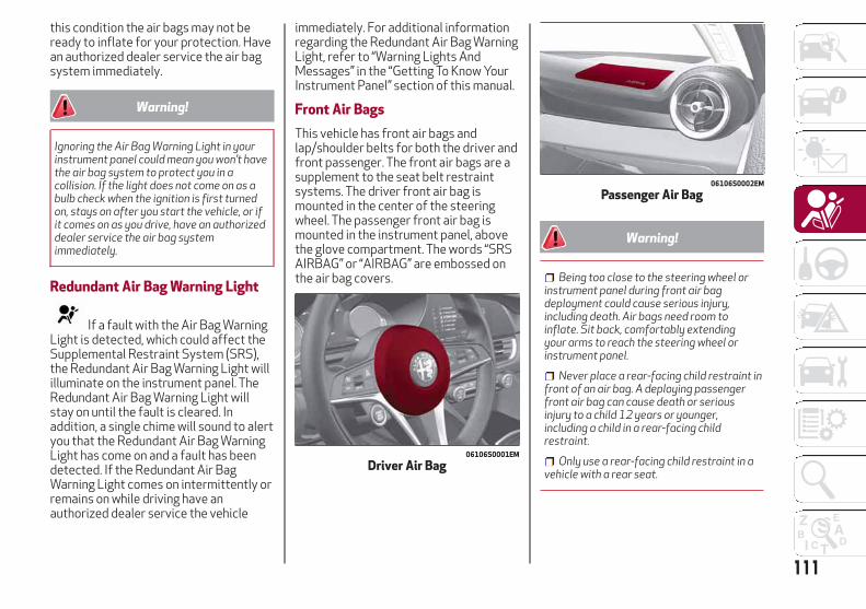
this condition the air bags may not beready to inflate for your protection. Havean authorized dealer service the air bagsystem immediately.
Warning!
Ignoring the Air Bag Warning Light in yourinstrument panel could mean you won’t havethe air bag system to protect you in acollision. If the light does not come on as abulb check when the ignition is first turnedon, stays on after you start the vehicle, or ifit comes on as you drive, have an authorizeddealer service the air bag systemimmediately.
Redundant Air Bag Warning Light
If a fault with the Air Bag WarningLight is detected, which could affect theSupplemental Restraint System (SRS),the Redundant Air Bag Warning Light willilluminate on the instrument panel. TheRedundant Air Bag Warning Light willstay on until the fault is cleared. Inaddition, a single chime will sound to alertyou that the Redundant Air Bag WarningLight has come on and a fault has beendetected. If the Redundant Air BagWarning Light comes on intermittently orremains on while driving have anauthorized dealer service the vehicle
immediately. For additional informationregarding the Redundant Air Bag WarningLight, refer to “Warning Lights AndMessages” in the “Getting To Know YourInstrument Panel” section of this manual.
Front Air Bags
This vehicle has front air bags andlap/shoulder belts for both the driver andfront passenger. The front air bags are asupplement to the seat belt restraintsystems. The driver front air bag ismounted in the center of the steeringwheel. The passenger front air bag ismounted in the instrument panel, abovethe glove compartment. The words “SRSAIRBAG” or “AIRBAG” are embossed onthe air bag covers.
Warning!
Being too close to the steering wheel orinstrument panel during front air bagdeployment could cause serious injury,including death. Air bags need room toinflate. Sit back, comfortably extendingyour arms to reach the steering wheel orinstrument panel.
Never place a rear-facing child restraint infront of an air bag. A deploying passengerfront air bag can cause death or seriousinjury to a child 12 years or younger,including a child in a rear-facing childrestraint.
Only use a rear-facing child restraint in avehicle with a rear seat.
06106S0001EM
Driver Air Bag
06106S0002EM
Passenger Air Bag
111
Driver And Passenger Front Air BagFeatures
The Advanced Front Air Bag system hasmultistage driver and front passenger airbags. This system provides outputappropriate to the severity and type ofcollision as determined by the OccupantRestraint Controller (ORC), which mayreceive information from the frontimpact sensors (if equipped) or othersystem components.The first stage inflator is triggeredimmediately during an impact thatrequires air bag deployment. A lowenergy output is used in less severecollisions. A higher energy output is usedfor more severe collisions.This vehicle may be equipped with adriver and/or front passenger seat beltbuckle switch that detects whether thedriver or front passenger seat belt isbuckled. The seat belt buckle switch mayadjust the inflation rate of the AdvancedFront Air Bags.This vehicle may be equipped with driverand/or front passenger seat trackposition sensors that may adjust theinflation rate of the Advanced Front AirBags based upon seat position.
Warning!
No objects should be placed over or nearthe air bag on the instrument panel orsteering wheel because any such objectscould cause harm if the vehicle is in acollision severe enough to cause the air bagto inflate.
Do not put anything on or around the airbag covers or attempt to open themmanually. You may damage the air bags andyou could be injured because the air bagsmay no longer be functional. The protectivecovers for the air bag cushions are designedto open only when the air bags are inflating.
Relying on the air bags alone could lead tomore severe injuries in a collision. The airbags work with your seat belt to restrainyou properly. In some collisions, air bagswon’t deploy at all. Always wear your seatbelts even though you have air bags.
Front Air Bag Operation
Front Air Bags are designed to provideadditional protection by supplementingthe seat belts. Front air bags are notexpected to reduce the risk of injury inrear, side, or rollover collisions. The frontair bags will not deploy in all frontalcollisions, including some that mayproduce substantial vehicle damage —for example, some pole collisions, truckunderrides, and angle offset collisions.
On the other hand, depending on the typeand location of impact, front air bags maydeploy in crashes with little vehiclefront-end damage but that produce asevere initial deceleration.Because air bag sensors measure vehicledeceleration over time, vehicle speed anddamage by themselves are not goodindicators of whether or not an air bagshould have deployed.Seat belts are necessary for yourprotection in all collisions, and also areneeded to help keep you in position, awayfrom an inflating air bag.When the ORC detects a collisionrequiring the front air bags, it signals theinflator units. A large quantity ofnon-toxic gas is generated to inflate thefront air bags.The steering wheel hub trim cover andthe upper right side of the instrumentpanel separate and fold out of the way asthe air bags inflate to their full size. Thefront air bags fully inflate in less timethan it takes to blink your eyes. The frontair bags then quickly deflate whilehelping to restrain the driver and frontpassenger.
112
SA
FE
TY
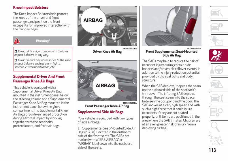
Knee Impact Bolsters
The Knee Impact Bolsters help protectthe knees of the driver and frontpassenger, and position the frontoccupants for improved interaction withthe front air bags.
Warning!
Do not drill, cut, or tamper with the kneeimpact bolsters in any way.
Do not mount any accessories to the kneeimpact bolsters such as alarm lights,stereos, citizen band radios, etc.
Supplemental Driver And FrontPassenger Knee Air Bags
This vehicle is equipped with aSupplemental Driver Knee Air Bagmounted in the instrument panel belowthe steering column and a SupplementalPassenger Knee Air Bag mounted in theinstrument panel below the glovecompartment. The Supplemental KneeAir Bags provide enhanced protectionduring a frontal impact by workingtogether with the seat belts,pretensioners, and front air bags.
Supplemental Side Air Bags
Your vehicle is equipped with two typesof side air bags:
1. Supplemental Seat-Mounted Side AirBags (SABs): Located in the outboardside of the front seats. The SABs aremarked with a “SRS AIRBAG” or“AIRBAG” label sewn into the outboardside of the seats.
The SABs may help to reduce the risk ofoccupant injury during certain sideimpacts and/or vehicle rollover events, inaddition to the injury reduction potentialprovided by the seat belts and bodystructure.
When the SAB deploys, it opens the seamon the outboard side of the seatback’strim cover. The inflating SAB deploysthrough the seat seam into the spacebetween the occupant and the door. TheSAB moves at a very high speed and withsuch a high force that it could injureoccupants if they are not seatedproperly, or if items are positioned in thearea where the SAB inflates. Children areat an even greater risk of injury from adeploying air bag.
06096S0102NA
Driver Knee Air Bag
06096S0103NA
Front Passenger Knee Air Bag
06106S0004EM
Front Supplemental Seat-MountedSide Air Bag
113
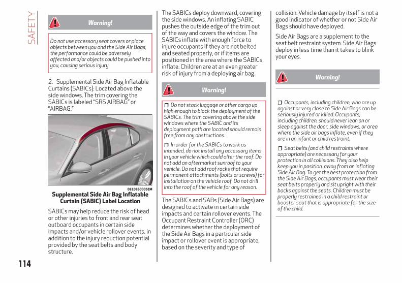
Warning!
Do not use accessory seat covers or placeobjects between you and the Side Air Bags;the performance could be adverselyaffected and/or objects could be pushed intoyou, causing serious injury.
2. Supplemental Side Air Bag InflatableCurtains (SABICs): Located above theside windows. The trim covering theSABICs is labeled “SRS AIRBAG” or“AIRBAG.”
SABICs may help reduce the risk of heador other injuries to front and rear seatoutboard occupants in certain sideimpacts and/or vehicle rollover events, inaddition to the injury reduction potentialprovided by the seat belts and bodystructure.
The SABICs deploy downward, coveringthe side windows. An inflating SABICpushes the outside edge of the trim outof the way and covers the window. TheSABICs inflate with enough force toinjure occupants if they are not beltedand seated properly, or if items arepositioned in the area where the SABICsinflate. Children are at an even greaterrisk of injury from a deploying air bag.
Warning!
Do not stack luggage or other cargo uphigh enough to block the deployment of theSABICs. The trim covering above the sidewindows where the SABIC and itsdeployment path are located should remainfree from any obstructions.
In order for the SABICs to work asintended, do not install any accessory itemsin your vehicle which could alter the roof. Donot add an aftermarket sunroof to yourvehicle. Do not add roof racks that requirepermanent attachments (bolts or screws) forinstallation on the vehicle roof. Do not drillinto the roof of the vehicle for any reason.
The SABICs and SABs (Side Air Bags) aredesigned to activate in certain sideimpacts and certain rollover events. TheOccupant Restraint Controller (ORC)determines whether the deployment ofthe Side Air Bags in a particular sideimpact or rollover event is appropriate,based on the severity and type of
collision. Vehicle damage by itself is not agood indicator of whether or not Side AirBags should have deployed.
Side Air Bags are a supplement to theseat belt restraint system. Side Air Bagsdeploy in less time than it takes to blinkyour eyes.
Warning!
Occupants, including children, who are upagainst or very close to Side Air Bags can beseriously injured or killed. Occupants,including children, should never lean on orsleep against the door, side windows, or areawhere the side air bags inflate, even if theyare in an infant or child restraint.
Seat belts (and child restraints whereappropriate) are necessary for yourprotection in all collisions. They also helpkeep you in position, away from an inflatingSide Air Bag. To get the best protection fromthe Side Air Bags, occupants must wear theirseat belts properly and sit upright with theirbacks against the seats. Children must beproperly restrained in a child restraint orbooster seat that is appropriate for the sizeof the child.
06106S0005EM
Supplemental Side Air Bag InflatableCurtain (SABIC) Label Location
114
SA
FE
TY

Warning!
Side Air Bags need room to inflate. Do notlean against the door or window. Sit uprightin the center of the seat.
Being too close to the Side Air Bagsduring deployment could cause you to beseverely injured or killed.
Relying on the Side Air Bags alone couldlead to more severe injuries in a collision. TheSide Air Bags work with your seat belt torestrain you properly. In some collisions, SideAir Bags won’t deploy at all. Always wearyour seat belt even though you have Side AirBags.
Note: Air bag covers may not be obviousin the interior trim, but they will openduring air bag deployment.Side Impacts
In side impacts, the side impact sensorsaid the ORC in determining theappropriate response to impact events.The system is calibrated to deploy theSide Air Bags on the impact side of thevehicle during impacts that require SideAir Bag occupant protection. In sideimpacts, the Side Air Bags deployindependently; a left side impact deploysthe left Side Air Bags only and a right sideimpact deploys the right Side Air Bagsonly.
The Side Air Bags will not deploy in allside collisions, including some collisionsat certain angles, or some side collisionsthat do not impact the area of thepassenger compartment. The Side AirBags may deploy during angled or offsetfrontal collisions where the front air bagsdeploy.Rollover Events
Side Air Bags are designed to activate incertain rollover events. The ORCdetermines whether the deployment ofthe Side Air Bags in a particular rolloverevent is appropriate, based on theseverity and type of collision. Vehicledamage by itself is not a good indicatorof whether or not Side Air Bags shouldhave deployed.The Side Air Bags will not deploy in allrollover events. The rollover sensingsystem determines if a rollover eventmay be in progress and whetherdeployment is appropriate. In the eventthe vehicle experiences a rollover or nearrollover event, and deployment of theSide Air Bags is appropriate, the rolloversensing system will also deploy the seatbelt pretensioners on both sides of thevehicle.The SABICs may help reduce the risk ofpartial or complete ejection of vehicleoccupants through side windows incertain rollover or side impact events.The Occupant Restraint Controller (ORC)monitors the internal circuits and
interconnecting wiring associated withelectrical Air Bag System Componentslisted below:
Air Bag System Components
Occupant Restraint Controller (ORC)
Air Bag Warning Light
Steering Wheel and Column
Instrument Panel
Knee Impact Bolsters
Driver and Front Passenger Air Bags
Supplemental Side Air Bags
Supplemental Knee Air Bags
Front and Side Impact Sensors
Seat Belt Pretensioners
Seat Track Position Sensors
Seat Belt Buckle Switch
If A Deployment Occurs
The front air bags are designed to deflateimmediately after deployment.Note: Front and/or side air bags will notdeploy in all collisions. This does notmean something is wrong with the air bagsystem.If you do have a collision which deploysthe air bags, any or all of the followingmay occur:
The air bag material may sometimescause abrasions and/or skin reddening to
115

the occupants as the air bags deploy andunfold. The abrasions are similar tofriction rope burns or those you might getsliding along a carpet or gymnasium floor.They are not caused by contact withchemicals. They are not permanent andnormally heal quickly. However, if youhaven’t healed significantly within a fewdays, or if you have any blistering, seeyour doctor immediately.
As the air bags deflate, you may seesome smoke-like particles. The particlesare a normal by-product of the processthat generates the non-toxic gas used forair bag inflation. These airborne particlesmay irritate the skin, eyes, nose, orthroat. If you have skin or eye irritation,rinse the area with cool water. For noseor throat irritation, move to fresh air. Ifthe irritation continues, see your doctor.If these particles settle on your clothing,follow the garment manufacturer’sinstructions for cleaning.
Do not drive your vehicle after the airbags have deployed. If you are involved inanother collision, the air bags will not bein place to protect you.
Warning!
Deployed air bags and seat belt pretensionerscannot protect you in another collision. Havethe air bags, seat belt pretensioners, and theseat belt retractor assemblies replaced by an
authorized dealer immediately. Also, have theOccupant Restraint Controller Systemserviced as well.
Note:
Air bag covers may not be obvious inthe interior trim, but they will openduring air bag deployment.
After any collision, the vehicle shouldbe taken to an authorized dealerimmediately.
Enhanced Accident ResponseSystem
In the event of an impact, if thecommunication network remains intact,and the power remains intact, dependingon the nature of the event, the ORC willdetermine whether to have the EnhancedAccident Response System perform thefollowing functions:
Cut off fuel to the engine.
Flash hazard lights as long as thebattery has power or until the hazardlight button is pressed. The hazard lightscan be deactivated by pressing thehazard light button.
Turn on the interior lights, whichremain on as long as the battery haspower or for 15 minutes from theintervention of the Enhanced AccidentResponse System.
Unlock the power door locks.
Turn off the Fuel Pump Heater(if equipped).
Turn off the HVAC Blower Motor.
Cut off battery power to the:
– Engine
– Electric power steering
– Brake booster
– Electric park brake
– Automatic transmission gearselector
– Horn
– Front wiper
– Headlamp washer pump
Enhanced Accident ResponseSystem Reset Procedure
After the event occurs, when the systemis active, a message regarding fuel cutoffis displayed. Turn the ignition switch fromignition AVV/START or MAR/ACC/ON/RUN to ignition STOP/OFF/LOCK.Carefully check the vehicle for fuel leaksin the engine compartment and on theground near the engine compartment andfuel tank before resetting the system andstarting the engine.Depending on the nature of the event theleft and right turn signal lights, located inthe instrument panel, may both beblinking and will continue to blink. In order
116
SA
FE
TY

to move your vehicle to the side of theroad, you must follow the system resetprocedure.
Customer Action Customer Will See
Note:Each step MUST BE held for at least two
seconds
1. Turn ignitionSTOP/OFF/LOCK.(Turn Signal Must beplaced in NeutralState).
2. Turn ignitionMAR/ACC/ON/RUN.
Right turn lightBLINKS.Left turn light is OFF.
3. Turn right turnsignal switch ON.
Right turn light is ONSOLID.Left turn lightBLINKS.
4. Place turn signal inneutral state.
Right turn light isOFF.Left turn lightBLINKS.
5. Turn left turn signalswitch ON.
Right turn lightBLINKS.Left turn light is ONSOLID.
6. Place turn signal inneutral state.
Right turn lightBLINKS.Left turn light is OFF.
Customer Action Customer Will See
Note:Each step MUST BE held for at least two
seconds
7. Turn right turnsignal switch ON.
Right turn light is ONSOLID.Left turn lightBLINKS.
8. Place turn signal inneutral state.
Right turn light isOFF.Left turn lightBLINKS.
9. Turn left turn signalswitch ON.
Right turn light is ONSOLID.Left turn light is ONSOLID.
10. Turn left turnsignal switch OFF.(Turn Signal SwitchMust be placed inNeutral State).
Right turn light isOFF.Left turn light is OFF.
11. Turn ignitionSTOP/OFF/LOCK.
12. Turn ignitionMAR/ACC/ON/RUN.(Entire sequenceneeds to becompleted within oneminute or sequencewill need to berepeated).
System is now resetand the engine maybe started.
Turn hazard flashersOFF (Manually).
If a reset procedure step is notcompleted within 60 seconds, then theturn signal lights will blink and the resetprocedure must be performed again inorder to be successful.
Maintaining Your Air Bag System
Warning!
Modifications to any part of the air bagsystem could cause it to fail when you needit. You could be injured if the air bag systemis not there to protect you. Do not modifythe components or wiring, including addingany kind of badges or stickers to thesteering wheel hub trim cover or the upperright side of the instrument panel. Do notmodify the front bumper, vehicle bodystructure, or add aftermarket side steps orrunning boards.
It is dangerous to try to repair any part ofthe air bag system yourself. Be sure to tellanyone who works on your vehicle that ithas an air bag system.
Do not attempt to modify any part of yourair bag system. The air bag may inflateaccidentally or may not function properly ifmodifications are made. Take your vehicleto an authorized dealer for any air bagsystem service. If your seat, including yourtrim cover and cushion, needs to be servicedin any way (including removal orloosening/tightening of seat attachmentbolts), take the vehicle to your authorizeddealer. Only manufacturer approved seat
117
accessories may be used. If it is necessaryto modify the air bag system for personswith disabilities, contact your authorizeddealer.
Event Data Recorder (EDR)
This vehicle is equipped with an eventdata recorder (EDR). The main purpose ofan EDR is to record, in certain crash ornear crash-like situations, such as an airbag deployment or hitting a roadobstacle, data that will assist inunderstanding how a vehicle’s systemsperformed. The EDR is designed torecord data related to vehicle dynamicsand safety systems for a short period oftime, typically 30 seconds or less. TheEDR in this vehicle is designed to recordsuch data as:
How various systems in your vehiclewere operating;
Whether or not the driver andpassenger safety belts werebuckled/fastened;
How far (if at all) the driver wasdepressing the accelerator and/or brakepedal; and,
How fast the vehicle was traveling.
These data can help provide a betterunderstanding of the circumstances inwhich crashes and injuries occur.
Note: EDR data are recorded by yourvehicle only if a non-trivial crash situationoccurs; no data are recorded by the EDRunder normal driving conditions and nopersonal data (e.g., name, gender, age,and crash location) are recorded.However, other parties, such as lawenforcement, could combine the EDRdata with the type of personallyidentifying data routinely acquired duringa crash investigation.To read data recorded by an EDR, specialequipment is required, and access to thevehicle or the EDR is needed. In additionto the vehicle manufacturer, otherparties, such as law enforcement, thathave the special equipment, can read theinformation if they have access to thevehicle or the EDR.
Child RestraintsEveryone in your vehicle needs to bebuckled up at all times, including babiesand children. Every state in the UnitedStates, and every Canadian province,requires that small children ride in properrestraint systems. This is the law, and youcan be prosecuted for ignoring it.Children 12 years or younger should rideproperly buckled up in a rear seat, ifavailable. According to crash statistics,children are safer when properlyrestrained in the rear seats rather than inthe front.
Warning!
In a collision, an unrestrained child canbecome a projectile inside the vehicle. Theforce required to hold even an infant on yourlap could become so great that you could nothold the child, no matter how strong you are.The child and others could be badly injured.Any child riding in your vehicle should be in aproper restraint for the child’s size.
There are different sizes and types ofrestraints for children from newborn sizeto the child almost large enough for anadult safety belt. Always check the childseat Owner’s Manual to make sure youhave the correct seat for your child.Carefully read and follow all theinstructions and warnings in the childrestraint Owner’s Manual and on all thelabels attached to the child restraint.Before buying any restraint system,make sure that it has a label certifyingthat it meets all applicable SafetyStandards. You should also make surethat you can install it in the vehicle whereyou will use it.
118
SA
FE
TY
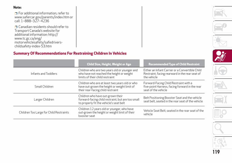
Note:
For additional information, refer towww.safercar.gov/parents/index.htm orcall: 1–888–327–4236
Canadian residents should refer toTransport Canada’s website foradditional information: http://www.tc.gc.ca/eng/motorvehiclesafety/safedrivers-childsafety-index-53.htm
Summary Of Recommendations For Restraining Children In Vehicles
Child Size, Height, Weight or Age Recommended Type of Child Restraint
Infants and ToddlersChildren who are two years old or younger andwho have not reached the height or weightlimits of their child restraint
Either an Infant Carrier or a Convertible ChildRestraint, facing rearward in the rear seat ofthe vehicle
Small ChildrenChildren who are at least two years old or whohave out-grown the height or weight limit oftheir rear-facing child restraint
Forward-Facing Child Restraint with afive-point Harness, facing forward in the rearseat of the vehicle
Larger ChildrenChildren who have out-grown theirforward-facing child restraint, but are too smallto properly fit the vehicle’s seat belt
Belt Positioning Booster Seat and the vehicleseat belt, seated in the rear seat of the vehicle
Children Too Large for Child RestraintsChildren 12 years old or younger, who haveout-grown the height or weight limit of theirbooster seat
Vehicle Seat Belt, seated in the rear seat of thevehicle
119

Infant And Child Restraints
Safety experts recommend that childrenride rear-facing in the vehicle until theyare two years old or until they reacheither the height or weight limit of theirrear-facing child restraint. Two types ofchild restraints can be used rear-facing:infant carriers and convertible childseats.The infant carrier is only used rear-facingin the vehicle. It is recommended forchildren from birth until they reach theweight or height limit of the infant carrier.Convertible child seats can be used eitherrear-facing or forward-facing in thevehicle. Convertible child seats oftenhave a higher weight limit in therear-facing direction than infant carriersdo, so they can be used rear-facing bychildren who have outgrown their infantcarrier but are still less than at least twoyears old. Children should remainrear-facing until they reach the highestweight or height allowed by theirconvertible child seat.
Warning!
Never place a rear-facing child restraint infront of an air bag. A deploying passengerfront air bag can cause death or seriousinjury to a child 12 years or younger,including a child in a rear-facing childrestraint.
Only use a rear-facing child restraint in avehicle with a rear seat.
Older Children And Child Restraints
Children who are two years old or whohave outgrown their rear-facingconvertible child seat can rideforward-facing in the vehicle.Forward-facing child seats andconvertible child seats used in theforward-facing direction are for childrenwho are over two years old or who haveoutgrown the rear-facing weight orheight limit of their rear-facingconvertible child seat. Children shouldremain in a forward-facing child seat witha harness for as long as possible, up tothe highest weight or height allowed bythe child seat.All children whose weight or height isabove the forward-facing limit for thechild seat should use a belt-positioningbooster seat until the vehicle’s seat beltsfit properly. If the child cannot sit withknees bent over the vehicle’s seatcushion while the child’s back is againstthe seatback, they should use abelt-positioning booster seat. The childand belt-positioning booster seat areheld in the vehicle by the seat belt.
Warning!
Improper installation can lead to failureof an infant or child restraint. It could comeloose in a collision. The child could be badlyinjured or killed. Follow the child restraintmanufacturer’s directions exactly wheninstalling an infant or child restraint.
After a child restraint is installed in thevehicle, do not move the vehicle seatforward or rearward because it can loosenthe child restraint attachments. Remove thechild restraint before adjusting the vehicleseat position. When the vehicle seat hasbeen adjusted, reinstall the child restraint.
When your child restraint is not in use,secure it in the vehicle with the seat belt orLATCH anchorages, or remove it from thevehicle. Do not leave it loose in the vehicle. Ina sudden stop or accident, it could strike theoccupants or seatbacks and cause seriouspersonal injury.
120
SA
FE
TY
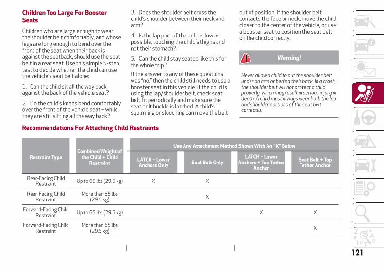
Children Too Large For BoosterSeats
Children who are large enough to wearthe shoulder belt comfortably, and whoselegs are long enough to bend over thefront of the seat when their back isagainst the seatback, should use the seatbelt in a rear seat. Use this simple 5-steptest to decide whether the child can usethe vehicle’s seat belt alone:
1. Can the child sit all the way backagainst the back of the vehicle seat?
2. Do the child’s knees bend comfortablyover the front of the vehicle seat – whilethey are still sitting all the way back?
3. Does the shoulder belt cross thechild’s shoulder between their neck andarm?
4. Is the lap part of the belt as low aspossible, touching the child’s thighs andnot their stomach?
5. Can the child stay seated like this forthe whole trip?
If the answer to any of these questionswas “no,” then the child still needs to use abooster seat in this vehicle. If the child isusing the lap/shoulder belt, check seatbelt fit periodically and make sure theseat belt buckle is latched. A child’ssquirming or slouching can move the belt
out of position. If the shoulder beltcontacts the face or neck, move the childcloser to the center of the vehicle, or usea booster seat to position the seat belton the child correctly.
Warning!
Never allow a child to put the shoulder beltunder an arm or behind their back. In a crash,the shoulder belt will not protect a childproperly, which may result in serious injury ordeath. A child must always wear both the lapand shoulder portions of the seat beltcorrectly.
Recommendations For Attaching Child Restraints
Restraint TypeCombined Weight of
the Child + ChildRestraint
Use Any Attachment Method Shown With An “X” Below
LATCH – LowerAnchors Only
Seat Belt OnlyLATCH – Lower
Anchors + Top TetherAnchor
Seat Belt + TopTether Anchor
Rear-Facing ChildRestraint
Up to 65 lbs (29.5 kg) X X
Rear-Facing ChildRestraint
More than 65 lbs(29.5 kg)
X
Forward-Facing ChildRestraint
Up to 65 lbs (29.5 kg) X X
Forward-Facing ChildRestraint
More than 65 lbs(29.5 kg)
X
121

Lower Anchors And Tethers ForCHildren (LATCH) Restraint System
Your vehicle is equipped with the childrestraint anchorage system calledLATCH, which stands for Lower Anchorsand Tethers for CHildren. The LATCH
system has three vehicle anchor pointsfor installing LATCH-equipped childseats. There are two lower anchorageslocated at the back of the seat cushionwhere it meets the seatback and one toptether anchorage located behind theseating position. These anchorages areused to install LATCH-equipped childseats without using the vehicle’s seatbelts. Some seating positions may have atop tether anchorage but no loweranchorages. In these seating positions,the seat belt must be used with the toptether anchorage to install the childrestraint. Please see the following tablefor more information.
LATCH Positions For Installing ChildRestraints In This Vehicle
Frequently Asked Questions About Installing Child Restraints With LATCH
What is the weight limit (child’s weight + weight of thechild restraint) for using the LATCH anchorage system toattach the child restraint?
65 lbs (29.5 kg)
Use the LATCH anchorage system until the combinedweight of the child and the child restraint is 65 lbs(29.5 kg). Use the seat belt and tether anchor instead ofthe LATCH system once the combined weight is morethan 65 lbs (29.5 kg).
Can the LATCH anchorages and the seat belt be usedtogether to attach a rear-facing or forward-facing childrestraint?
No
Do not use the seat belt when you use the LATCHanchorage system to attach a rear-facing orforward-facing child restraint.Booster seats may be attached to the LATCH anchoragesif allowed by the booster seat manufacturer. See yourbooster seat owner’s manual for more information.
Can a child seat be installed in the center position usingthe inner LATCH lower anchorage?
NoUse the seat belt and tether anchor to install a child seatin the center seating position.
022668173
LATCH Label
06086S0101NA
LATCH Positions
Lower Anchorage Symbol(2 Anchorages Per Seating Position)
Top Tether Anchorage Symbol
122
SA
FE
TY

Frequently Asked Questions About Installing Child Restraints With LATCH
Can two child restraints be attached using a commonlower LATCH anchorage?
No
Never “share” a LATCH anchorage with two or more childrestraints. If the center position does not have dedicatedLATCH lower anchorages, use the seat belt to install achild seat in the center position next to a child seat usingthe LATCH anchorages in an outboard position.
Can the rear-facing child restraint touch the back of thefront passenger seat?
Yes
The child seat may touch the back of the front passengerseat if the child restraint manufacturer also allowscontact. See your child restraint owner’s manual for moreinformation.
Can the head restraints be removed? Yes All rear passenger head restraints can be removed.
Locating The LATCH Anchorages
The lower anchoragesare round bars that arefound at the rear of theseat cushion where itmeets the seatback,below the anchoragesymbols on theseatback. They are just
visible when you lean into the rear seat toinstall the child restraint. You will easilyfeel them if you run your finger along thegap between the seatback and seatcushion.
06086S0009EM
LATCH Anchorage Locations
1 — LATCH Anchorage Bar2 — LATCH Anchorage Locations
123
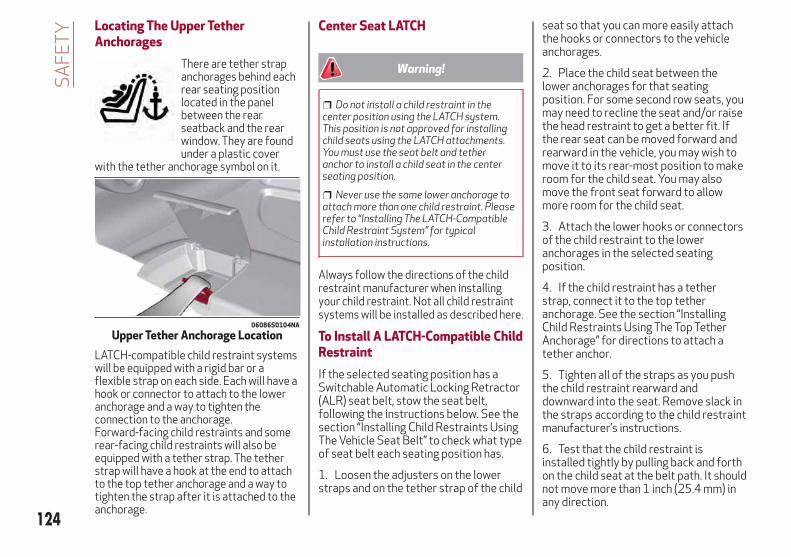
Locating The Upper TetherAnchorages
There are tether strapanchorages behind eachrear seating positionlocated in the panelbetween the rearseatback and the rearwindow. They are foundunder a plastic cover
with the tether anchorage symbol on it.
LATCH-compatible child restraint systemswill be equipped with a rigid bar or aflexible strap on each side. Each will have ahook or connector to attach to the loweranchorage and a way to tighten theconnection to the anchorage.Forward-facing child restraints and somerear-facing child restraints will also beequipped with a tether strap. The tetherstrap will have a hook at the end to attachto the top tether anchorage and a way totighten the strap after it is attached to theanchorage.
Center Seat LATCH
Warning!
Do not install a child restraint in thecenter position using the LATCH system.This position is not approved for installingchild seats using the LATCH attachments.You must use the seat belt and tetheranchor to install a child seat in the centerseating position.
Never use the same lower anchorage toattach more than one child restraint. Pleaserefer to “Installing The LATCH-CompatibleChild Restraint System” for typicalinstallation instructions.
Always follow the directions of the childrestraint manufacturer when installingyour child restraint. Not all child restraintsystems will be installed as described here.
To Install A LATCH-Compatible ChildRestraint
If the selected seating position has aSwitchable Automatic Locking Retractor(ALR) seat belt, stow the seat belt,following the instructions below. See thesection “Installing Child Restraints UsingThe Vehicle Seat Belt” to check what typeof seat belt each seating position has.
1. Loosen the adjusters on the lowerstraps and on the tether strap of the child
seat so that you can more easily attachthe hooks or connectors to the vehicleanchorages.
2. Place the child seat between thelower anchorages for that seatingposition. For some second row seats, youmay need to recline the seat and/or raisethe head restraint to get a better fit. Ifthe rear seat can be moved forward andrearward in the vehicle, you may wish tomove it to its rear-most position to makeroom for the child seat. You may alsomove the front seat forward to allowmore room for the child seat.
3. Attach the lower hooks or connectorsof the child restraint to the loweranchorages in the selected seatingposition.
4. If the child restraint has a tetherstrap, connect it to the top tetheranchorage. See the section “InstallingChild Restraints Using The Top TetherAnchorage” for directions to attach atether anchor.
5. Tighten all of the straps as you pushthe child restraint rearward anddownward into the seat. Remove slack inthe straps according to the child restraintmanufacturer’s instructions.
6. Test that the child restraint isinstalled tightly by pulling back and forthon the child seat at the belt path. It shouldnot move more than 1 inch (25.4 mm) inany direction.
06086S0104NA
Upper Tether Anchorage Location
124
SA
FE
TY

How To Stow An UnusedSwitchable-ALR (ALR) Seat Belt:
When using the LATCH attaching systemto install a child restraint, stow all ALRseat belts that are not being used byother occupants or being used to securechild restraints. An unused belt couldinjure a child if they play with it andaccidentally lock the seat belt retractor.Before installing a child restraint usingthe LATCH system, buckle the seat beltbehind the child restraint and out of thechild’s reach. If the buckled seat beltinterferes with the child restraintinstallation, instead of buckling it behindthe child restraint, route the seat beltthrough the child restraint belt path andthen buckle it. Do not lock the seat belt.Remind all children in the vehicle that theseat belts are not toys and that theyshould not play with them.
Warning!
Improper installation of a child restraintto the LATCH anchorages can lead to failureof the restraint. The child could be badlyinjured or killed. Follow the child restraintmanufacturer’s directions exactly wheninstalling an infant or child restraint.
Child restraint anchorages are designedto withstand only those loads imposed bycorrectly-fitted child restraints. Under nocircumstances are they to be used for adultseat belts, harnesses, or for attaching otheritems or equipment to the vehicle.
Installing Child Restraints UsingThe Vehicle Seat Belt
Child restraint systems are designed tobe secured in vehicle seats by lap belts orthe lap belt portion of a lap/shoulder belt.
Warning!
Improper installation or failure toproperly secure a child restraint can lead tofailure of the restraint. The child could bebadly injured or killed.
Follow the child restraint manufacturer’sdirections exactly when installing an infantor child restraint.
The seat belts in the passenger seatingpositions are equipped with a SwitchableAutomatic Locking Retractor (ALR) thatis designed to keep the lap portion of theseat belt tight around the child restraintso that it is not necessary to use a lockingclip. The ALR retractor can be “switched”
into a locked mode by pulling all of thewebbing out of the retractor and thenletting the webbing retract back into theretractor. If it is locked, the ALR will makea clicking noise while the webbing ispulled back into the retractor. Refer tothe “Automatic Locking Mode”description in “Switchable AutomaticLocking Retractors (ALR)” under“Occupant Restraint Systems” foradditional information on ALR.Please see the table below and thefollowing sections for more information.
Lap/Shoulder Belt Systems ForInstalling Child Restraints In ThisVehicle
06086S0102NA
Automatic Locking Retractor (ALR)Locations
ALR = Switchable Automatic LockingRetractor
Top Tether Anchorage Symbol
125

Frequently Asked Questions About Installing Child Restraints With Seat Belts
What is the weight limit (child’s weight + weightof the child restraint) for using the TetherAnchor with the seat belt to attach a forwardfacing child restraint?
Weight limit of the Child Restraint
Always use the tether anchor when using theseat belt to install a forward facing childrestraint, up to the recommended weight limitof the child restraint.
Can the rear-facing child restraint touch theback of the front passenger seat?
YesContact between the front passenger seat andthe child restraint is allowed, if the childrestraint manufacturer also allows contact.
Can the head restraints be removed? YesAll rear passenger head restraints can beremoved.
Can the buckle stalk be twisted to tighten theseat belt against the belt path of the childrestraint?
NoDo not twist the buckle stalk in a seatingposition with an ALR retractor.
Installing A Child Restraint With ASwitchable Automatic LockingRetractor (ALR):
Child restraint systems are designed tobe secured in vehicle seats by lap belts orthe lap belt portion of a lap/shoulder belt.
Warning!
Improper installation or failure toproperly secure a child restraint can lead tofailure of the restraint. The child could bebadly injured or killed.
Follow the child restraint manufacturer’sdirections exactly when installing an infantor child restraint.
1. Place the child seat in the center ofthe seating position. For some secondrow seats, you may need to recline theseat and/or raise the head restraint toget a better fit. If the rear seat can bemoved forward and rearward in thevehicle, you may wish to move it to itsrear-most position to make room for thechild seat. You may also move the frontseat forward to allow more room for thechild seat.
2. Pull enough of the seat belt webbingfrom the retractor to pass it through thebelt path of the child restraint. Do nottwist the belt webbing in the belt path.
3. Slide the latch plate into the buckleuntil you hear a “click.”
4. Pull on the webbing to make the lapportion tight against the child seat.
5. To lock the seat belt, pull down on theshoulder part of the belt until you havepulled all the seat belt webbing out of theretractor. Then, allow the webbing toretract back into the retractor. As thewebbing retracts, you will hear a clickingsound. This means the seat belt is now inthe Automatic Locking mode.
6. Try to pull the webbing out of theretractor. If it is locked, you should not beable to pull out any webbing. If theretractor is not locked, repeat step 5.
7. Finally, pull up on any excess webbingto tighten the lap portion around the childrestraint while you push the childrestraint rearward and downward intothe vehicle seat.
126
SA
FE
TY

8. If the child restraint has a top tetherstrap and the seating position has a toptether anchorage, connect the tetherstrap to the anchorage and tighten thetether strap. See the section “InstallingChild Restraints Using the Top TetherAnchorage” for directions to attach atether anchor.
9. Test that the child restraint isinstalled tightly by pulling back and forthon the child seat at the belt path. It shouldnot move more than 1 inch (25.4 mm) inany direction.
Any seat belt system will loosen withtime, so check the belt occasionally, andpull it tight if necessary.
Installing Child Restraints UsingThe Top Tether Anchorage:
Warning!
Do not attach a tether strap for arear-facing car seat to any location in frontof the car seat, including the seat frame or atether anchorage. Only attach the tetherstrap of a rear-facing car seat to the tetheranchorage that is approved for that seatingposition, located behind the top of thevehicle seat. See the section “Lower Anchors
and Tethers for CHildren (LATCH) RestraintSystem” for the location of approved tetheranchorages in your vehicle.
1. Look behind the seating positionwhere you plan to install the childrestraint to find the tether anchorage.You may need to move the seat forwardto provide better access to the tetheranchorage. If there is no top tetheranchorage for that seating position,move the child restraint to anotherposition in the vehicle if one is available.
2. Rotate or lift the cover to access theanchor directly behind the seat whereyou are placing the child restraint.
3. Route the tether strap to provide themost direct path for the strap betweenthe anchor and the child seat. If yourvehicle is equipped with adjustable rearhead restraints, raise the head restraint,and where possible, route the tetherstrap under the head restraint andbetween the two posts. If not possible,lower the head restraint and pass thetether strap around the outboard side ofthe head restraint.
4. Attach the tether strap hook of thechild restraint to the top tetheranchorage as shown in the diagram.
5. Remove slack in the tether strapaccording to the child restraintmanufacturer’s instructions.
Warning!
An incorrectly anchored tether strapcould lead to increased head motion andpossible injury to the child. Use only theanchorage position directly behind the childseat to secure a child restraint top tetherstrap.
If your vehicle is equipped with a split rearseat, make sure the tether strap does notslip into the opening between the seatbacksas you remove slack in the strap.
06086S0104NA
Upper Tether Anchorage Location
127

Transporting PetsAir Bags deploying in the front seat couldharm your pet. An unrestrained pet will bethrown about and possibly injured, orinjure a passenger during panic braking orin a collision.Pets should be restrained in the rear seatin pet harnesses or pet carriers that aresecured by seat belts.
SAFETY TIPSTransporting PassengersNEVER TRANSPORT PASSENGERS INTHE CARGO AREA.
Warning!
Do not leave children or animals insideparked vehicles in hot weather. Interior heatbuild-up may cause serious injury or death.
It is extremely dangerous to ride in acargo area, inside or outside of a vehicle. Ina collision, people riding in these areas aremore likely to be seriously injured or killed.
Do not allow people to ride in any area ofyour vehicle that is not equipped with seatsand seat belts.
Be sure everyone in your vehicle is in aseat and using a seat belt properly.
Exhaust Gas
Warning!
Exhaust gases can injure or kill. They containcarbon monoxide (CO), which is colorless andodorless. Breathing it can make youunconscious and can eventually poison you.
To avoid breathing (CO), follow these safetytips:
Do not run the engine in a closed garageor in confined areas any longer than neededto move your vehicle in or out of the area.
If you are required to drive with thetrunk/liftgate/rear doors open, make surethat all windows are closed and the climatecontrol BLOWER switch is set at high speed.DO NOT use the recirculation mode.
If it is necessary to sit in a parked vehiclewith the engine running, adjust your heatingor cooling controls to force outside air intothe vehicle. Set the blower at high speed.
The best protection against carbonmonoxide entry into the vehicle body is aproperly maintained engine exhaustsystem.Whenever a change is noticed in thesound of the exhaust system, whenexhaust fumes can be detected inside thevehicle, or when the underside or rear ofthe vehicle is damaged, have a competentmechanic inspect the complete exhaustsystem and adjacent body areas forbroken, damaged, deteriorated, ormispositioned parts. Open seams orloose connections could permit exhaustfumes to seep into the passengercompartment. In addition, inspect theexhaust system each time the vehicle israised for lubrication or oil change.Replace as required.
128
SA
FE
TY
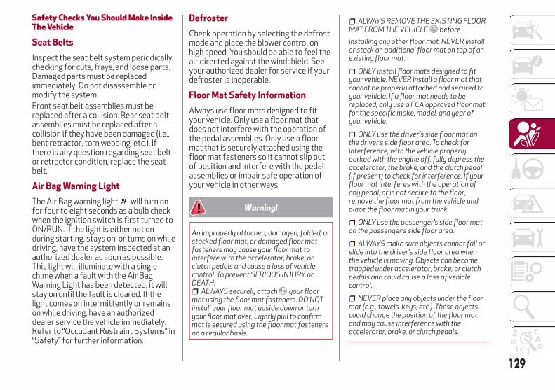
Safety Checks You Should Make InsideThe Vehicle
Seat Belts
Inspect the seat belt system periodically,checking for cuts, frays, and loose parts.Damaged parts must be replacedimmediately. Do not disassemble ormodify the system.Front seat belt assemblies must bereplaced after a collision. Rear seat beltassemblies must be replaced after acollision if they have been damaged (i.e.,bent retractor, torn webbing, etc.). Ifthere is any question regarding seat beltor retractor condition, replace the seatbelt.
Air Bag Warning Light
The Air Bag warning light will turn onfor four to eight seconds as a bulb checkwhen the ignition switch is first turned toON/RUN. If the light is either not onduring starting, stays on, or turns on whiledriving, have the system inspected at anauthorized dealer as soon as possible.This light will illuminate with a singlechime when a fault with the Air BagWarning Light has been detected, it willstay on until the fault is cleared. If thelight comes on intermittently or remainson while driving, have an authorizeddealer service the vehicle immediately.Refer to “Occupant Restraint Systems” in“Safety” for further information.
Defroster
Check operation by selecting the defrostmode and place the blower control onhigh speed. You should be able to feel theair directed against the windshield. Seeyour authorized dealer for service if yourdefroster is inoperable.
Floor Mat Safety Information
Always use floor mats designed to fityour vehicle. Only use a floor mat thatdoes not interfere with the operation ofthe pedal assemblies. Only use a floormat that is securely attached using thefloor mat fasteners so it cannot slip outof position and interfere with the pedalassemblies or impair safe operation ofyour vehicle in other ways.
Warning!
An improperly attached, damaged, folded, orstacked floor mat, or damaged floor matfasteners may cause your floor mat tointerfere with the accelerator, brake, orclutch pedals and cause a loss of vehiclecontrol. To prevent SERIOUS INJURY orDEATH:
ALWAYS securely attach your floormat using the floor mat fasteners. DO NOTinstall your floor mat upside down or turnyour floor mat over. Lightly pull to confirmmat is secured using the floor mat fastenerson a regular basis.
ALWAYS REMOVE THE EXISTING FLOORMAT FROM THE VEHICLE before
installing any other floor mat. NEVER installor stack an additional floor mat on top of anexisting floor mat.
ONLY install floor mats designed to fityour vehicle. NEVER install a floor mat thatcannot be properly attached and secured toyour vehicle. If a floor mat needs to bereplaced, only use a FCA approved floor matfor the specific make, model, and year ofyour vehicle.
ONLY use the driver’s side floor mat onthe driver’s side floor area. To check forinterference, with the vehicle properlyparked with the engine off, fully depress theaccelerator, the brake, and the clutch pedal(if present) to check for interference. If yourfloor mat interferes with the operation ofany pedal, or is not secure to the floor,remove the floor mat from the vehicle andplace the floor mat in your trunk.
ONLY use the passenger’s side floor maton the passenger’s side floor area.
ALWAYS make sure objects cannot fall orslide into the driver’s side floor area whenthe vehicle is moving. Objects can becometrapped under accelerator, brake, or clutchpedals and could cause a loss of vehiclecontrol.
NEVER place any objects under the floormat (e.g., towels, keys, etc.). These objectscould change the position of the floor matand may cause interference with theaccelerator, brake, or clutch pedals.
129

If the vehicle carpet has been removedand re-installed, always properly attachcarpet to the floor and check the floor matfasteners are secure to the vehicle carpet.Fully depress each pedal to check for
interference with the accelerator, brake, orclutch pedals then re-install the floor mats.
It is recommended to only use mild soapand water to clean your floor mats. Aftercleaning, always check your floor mat hasbeen properly installed and is secured toyour vehicle using the floor mat fastenersby lightly pulling mat.
Periodic Safety Checks You ShouldMake Outside The Vehicle
Tires
Examine tires for excessive tread wearand uneven wear patterns. Check forstones, nails, glass, or other objectslodged in the tread or sidewall. Inspectthe tread for cuts and cracks. Inspectsidewalls for cuts, cracks, and bulges.Check the wheel nuts for tightness.Check the tires (including spare) forproper cold inflation pressure.
Lights
Have someone observe the operation ofbrake lights and exterior lights while youwork the controls. Check turn signal andhigh beam indicator lights on theinstrument panel.
Door Latches
Check for proper closing, latching, andlocking.
Fluid Leaks
Check area under vehicle after overnightparking for fuel, coolant, oil, or other fluidleaks. Also, if gasoline fumes aredetected or if fuel, or brake fluid leaksare suspected. The cause should belocated and corrected immediately.
130
SA
FE
TY

STARTING AND OPERATING
Let’s get to the core of the vehicle, andsee how you can explore its fullestpotential. We’ll look at how to drivesafely in any situation, making it awelcome companion with our comfortand wallets in mind.
STARTING THE ENGINE . . . . . . . .132ENGINE BLOCK HEATER —IF EQUIPPED . . . . . . . . . . . . . . .135ELECTRIC PARK BRAKE . . . . . . . .135AUTOMATIC TRANSMISSION. . . . .138ALFA DNA SELECTOR . . . . . . . . .143ALFA ACTIVE SUSPENSION(AAS) — IF EQUIPPED . . . . . . . . .146STOP/START SYSTEM . . . . . . . . .146SPEED LIMITER . . . . . . . . . . . . .148ELECTRONIC SPEED CONTROL(CRUISE CONTROL) . . . . . . . . . .149ADAPTIVE CRUISE CONTROL(ACC) — IF EQUIPPED . . . . . . . . .151PARK SENSORS SYSTEM . . . . . . .158LANE DEPARTURE WARNING(LDW) SYSTEM . . . . . . . . . . . . .163REAR BACK-UP CAMERA / DYNAMICGRIDLINES . . . . . . . . . . . . . . .166REFUELING THE VEHICLE . . . . . . .168VEHICLE LOADING . . . . . . . . . . .169TRAILER TOWING . . . . . . . . . . . .170SUGGESTIONS FOR DRIVING. . . . .171
131
STARTING THE ENGINEBefore starting the engine, be sure toadjust the seat, the interior rear viewmirrors, and the door mirrors, and fastenthe seat belt correctly.Never press the accelerator pedal beforestarting the engine.If necessary, messages indicating thestarting procedure can be shown in thedisplay.
Warning!
When leaving the vehicle, always removethe key fob from the vehicle and lock yourvehicle.
Never leave children alone in a vehicle, orwith access to an unlocked vehicle.
Allowing children to be in a vehicleunattended is dangerous for a number ofreasons. A child or others could be seriouslyor fatally injured. Children should be warnednot to touch the parking brake, brake pedalor the transmission gear selector.
Do not leave the key fob in or near thevehicle, or in a location accessible tochildren. A child could operate powerwindows, other controls, or move thevehicle.
Do not leave children or animals insideparked vehicles in hot weather. Interior heatbuild-up may cause serious injury or death.
Starting ProcedureProceed as follows:
1. Apply the electric park brake and setthe gear selector to PARK (P) orNEUTRAL (N).
2. Fully depress the brake pedal withouttouching the accelerator.
3. Briefly push the ignition button.
4. If the engine doesn't start within a fewseconds, you need to repeat theprocedure.
If the problem persists, contact anauthorized dealer.
Warning!
Never pour fuel or other flammable liquidinto the throttle body air inlet opening in anattempt to start the vehicle. This couldresult in flash fire causing serious personalinjury.
Do not attempt to push or tow yourvehicle to get it started. Vehicles equippedwith an automatic transmission cannot bestarted this way. Unburned fuel could enterthe catalytic converter and once the enginehas started, ignite and damage theconverter and vehicle.
If the vehicle has a discharged battery,booster cables may be used to obtain astart from a booster battery or the battery
in another vehicle. This type of start can bedangerous if done improperly. Refer to“Emergency Starting” in “In Case OfEmergency” for further information.
Caution!
To prevent damage to the starter, do notcontinuously crank the engine for more than25 seconds at a time. Wait 60 secondsbefore trying again.
Remote Starting System —If EquippedThis system uses the key fob to start theengine conveniently from outside thevehicle while still maintaining security.The system has a range of at least 300feet (91 meters).The remote starting system alsoactivates the climate control (ifequipped), the heated seats (if equipped),and the heated steering wheel (ifequipped), depending on temperaturesoutside and inside of the vehicle.
Note:
The vehicle must be equipped with anautomatic transmission in order toinclude remote start.
Obstructions between the vehicleand key fob may reduce this range.
132
STA
RT
ING
AN
DO
PE
RAT
ING

How to use Remote Start
All of the following conditions must bemet before the engine will remote start:
Gear selector in PARK (P).
Doors closed.
Hood closed.
Trunk closed.
Hazard switch off.
Brake switch inactive (brake pedal notpressed).
Battery at an acceptable charge level.
PANIC button not pushed.
System not disabled from previousremote start event.
Vehicle alarm system indicatorflashing.
Ignition in the OFF mode (if equippedwith keyless ignition system).
Fuel level meets minimumrequirement.
Remote Start Comfort Systems —If Equipped
When Remote Start is activated, theheated steering wheel and driver heatedseat features will automatically turn on incold weather.These features will stay on through theduration of remote start also until theignition is cycled to the ON/RUN mode.
Remote Start Windshield Wiper De–IcerActivation — If Equipped
When remote start is active and theoutside ambient temperature is less than39°F (4°C), the Windshield Wiper De-Icerwill be enabled. Exiting remote start willresume previous operation, except if theWindshield Wiper De-Icer is active.The Windshield Wiper De-Icer timer andoperation will continue.
Cold Weather OperationTo prevent possible engine damage whilestarting at low temperatures, this vehiclewill inhibit engine cranking when theambient temperature is less than –22° F(–30° C) and the oil temperature sensorreading indicates an engine block heaterhas not been used. An externally-poweredelectric engine block heater is available asoptional equipment or from yourauthorized dealer.The message “plug in engine heater” will bedisplayed in the instrument cluster whenthe ambient temperature is below 5° F(–15° C) at the time the engine is shut offas a reminder to avoid possible crankdelays at the next cold start.
Caution!
Use of the recommended oil and adhering tothe prescribed oil change intervals isimportant to prevent engine damage andensure satisfactory starting in coldconditions.
Extended Park StartingIf the vehicle has not been started ordriven for at least 35 days, it is advisableto follow the indications below.To start the engine, proceed as follows:
1. Briefly push the ignition button
2. If the engine does not start, wait fiveseconds and let the starter cool down andthen repeat the starting procedure
3. If the engine does not start after eightattempts, let the starter cool down for atleast 10 seconds, and then repeat thestarting procedure
If the problem persists, contact yourauthorized dealer.Note: After prolonged vehicle inactivity,very difficult starting, that can be noticedthrough rapid fatigue of the starter,might also be due to a dischargedbattery. In this case, see the "EmergencyStarting" section in the "In Case OfEmergency" chapter.
If Engine Fails To StartStarting the Engine with Key FobBattery Run Down or Drained
If the ignition does not respond when thebutton is pushed, the key fob batterymight be run down or drained. Therefore,the system does not detect the presenceof the key fob in the vehicle, and willdisplay a dedicated message.In this case, follow the instructionsoutlined in "Starting With A Discharged 133

Key Fob Battery" in the "Getting To KnowYour Vehicle" chapter, and start theengine normally.
Warning!
Never pour fuel or other flammable liquidinto the throttle body air inlet opening in anattempt to start the vehicle. This couldresult in flash fire causing serious personalinjury.
Do not attempt to push or tow yourvehicle to get it started. Vehicles equippedwith an automatic transmission cannot bestarted this way. Unburned fuel could enterthe catalytic converter and once the enginehas started, ignite and damage theconverter and vehicle.
If the vehicle has a discharged battery,booster cables may be used to obtain astart from a booster battery or the batteryin another vehicle. This type of start can bedangerous if done improperly. Refer to“Emergency Starting” in “In Case OfEmergency” for further information.
Caution!
To prevent damage to the starter, do notcontinuously crank the engine for more than25 seconds at a time. Wait 60 secondsbefore trying again.
After Starting — Warming Up TheEngineProceed as follows:
Travel slowly, letting the engine run ata reduced RPM, without acceleratingsuddenly.
It is recommended to wait until thedigital engine coolant temperatureindicator starts to rise for maximumperformance.
Stopping The EngineTo stop the engine, proceed as follows:
1. Park the vehicle in a position that isnot dangerous for oncoming traffic.
2. Engage the PARK (P) mode.
3. With engine idling, push theSTART/STOP button on the steeringwheel to STOP the engine.
Note: Do not leave the ignition in ONmode when the engine is off.To shut off the engine with vehicle speedgreater than 5 mph (8 km/h), you mustpush and hold the ignition or push theSTART/STOP button three timesconsecutively within a few seconds. Theengine will shut down, and the ignition willbe placed in the ON modeWith the keyless ignition system, it ispossible to go away from the vehicletaking the key fob with you, without theengine switching off. The vehicle will
inform about the absence of the key onboard, only if the doors are closed.Stopping the engine (cycling from the ONto the STOP position) the accessories arestill powered for about three minutes, oruntil a door is opened.When the ignition is in the STOP/OFFmode, the window switches remain activefor three minutes. Opening a front doorwill cancel this function.After severe driving, idle the engine toallow the temperature inside the enginecompartment to cool before shutting offthe engine.
Turbocharger Cool DownIt is recommended before switching thevehicle off, to keep the engine idling for afew minutes so that the turbocharger canbe suitably lubricated. This procedure isparticularly recommended after severedriving.After a full load operation, keep theengine idling for three to five minutesbefore switching it off.This time allows the lubricating oil andthe engine coolant to eliminate theexcessive heat from combustionchamber, bearings, inner components andturbocharger.
134
STA
RT
ING
AN
DO
PE
RAT
ING
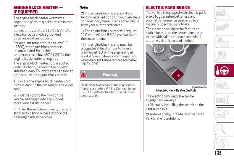
ENGINE BLOCK HEATER —IF EQUIPPEDThe engine block heater warms theengine and permits quicker starts in coldweather.Connect the cord to a 110-115 Volt ACelectrical outlet with a grounded,three-wire extension cord.For ambient temperatures below 0°F(-18°C), the engine block heater isrecommended. For ambienttemperatures below -20°F (-29°C), theengine block heater is required.The engine block heater cord is routedunder the hood, behind to the driver’sside headlamp. Follow the steps below toproperly use the engine block heater:
1. Locate the engine block heater cord(access door on the passenger side wipercowl).
2. Pull the cord to the front of thevehicle and plug it into a grounded,three-wire extension cord.
3. After the vehicle is running, properlystow away behind access door on thepassenger side wiper cowl.
Note:
The engine block heater cord is afactory installed option. If your vehicle isnot equipped, heater cords are availablefrom your authorized dealer.
The engine block heater will require110 Volts AC and 6.5 Amps to activatethe heater element.
The engine block heater must beplugged in at least 1 hour to have awarming effect on the engine and atleast 4 hours to have a warming effectwhen ambient temperatures are below-20 F (-29 C)
Warning!
Remember to disconnect the engine blockheater cord before driving. Damage to the110-115 Volt electrical cord could causeelectrocution.
ELECTRIC PARK BRAKEThe vehicle is equipped with electric parkbrake to guarantee better use andoptimal performance compared to amanually operated park brake.The electric parking brake features aswitch located on the center console, amotor with caliper for each rear wheel,and an electronic control module.
The electric parking brake can beengaged in two ways:
Manually, by pulling the switch on thecenter console.
Automatically, in "Safe Hold" or "AutoPark Brake" conditions.
07046S0001EM
Electric Park Brake Switch
135

Note: Normally, the electric parkingbrake is engaged automatically when theengine is stopped. This function can bedeactivated/activated on theInformation and Entertainment systemby selecting the following items insequence on the main menu: "Settings","Driver Assistance" and "AutomaticParking Brake".In addition to engaging the electric parkbrake, along with steering and positioningchocks in front of the wheels (when on asteep slope), you must always place thevehicle in the PARK (P) mode beforeleaving.Should the vehicle battery be faulty, thebattery must be replaced in order tounlock the electric park brake.
Engaging The Park Brake Manually
Briefly pull the switch located on thecenter console to manually engage theelectric park brake when the vehicle isstationary.Noise may be heard from the rear of thevehicle when engaging the electricparking brake.A slight movement of the brake pedalmay be detected when engaging theelectric parking brake with the brakepedal pressed.With the electric parking brake engaged,the BRAKE warning light on theinstrument panel and the switch willilluminate.
Caution!
With the Electronic Parking Brake failurewarning light on, some functions of theelectric parking brake are deactivated. Inthis case the driver is responsible for brakeactivation and vehicle parking in completesafety conditions.
If, under exceptional circumstances, theuse of the brake is required with thevehicle in motion, keep the switch on thecenter console pulled as long as the brakeaction is necessary.The BRAKE warning light may turn onwith the hydraulic system temporarilyunavailable, in this case braking iscontrolled by the motors.The brake lights will also automaticallyturn on in the same way as for normalbraking with the use of the brake pedal.Release the switch on the center consoleto stop the braking action with thevehicle in motion.If, through this procedure, the vehicle isbraked until a speed below 1.9 mph(3 km/h) is reached and the switch is keptpulled, the park brake will definitivelyengage.Note: Driving the vehicle with theelectric parking brake engaged, or usingit several times to slow down the vehicle,may cause severe damage to the brakingsystem.
Disengaging The Electric Park BrakeManually
In order to manually release the parkbrake, the ignition should be in the ONmode. Press the brake pedal, and thenpush the switch on the center consolebriefly.Noise may be heard from the rear of thevehicle, and a slight movement of thebrake pedal may be detected duringdisengagement.After disengaging the electric parkingbrake, the BRAKE warning light on theinstrument panel and the light on theswitch will turn off.If the BRAKE warning light on theinstrument panel remains on with theelectric parking brake disengaged, thisindicates a fault: in this case, contact anauthorized dealer.
Warning!
Never leave children alone in a vehicle, orwith access to an unlocked vehicle.
Allowing children to be in a vehicleunattended is dangerous for a number ofreasons. A child or others could be seriouslyor fatally injured. Children should be warnednot to touch the park brake, brake pedal orthe gear selector.
136
STA
RT
ING
AN
DO
PE
RAT
ING

Do not leave the key fob in or near thevehicle or in a location accessible tochildren. A child could operate powerwindows, other controls, or move thevehicle.
Be sure the park brake is fully disengagedbefore driving; failure to do so can lead tobrake failure and a collision.
Always fully apply the park brake whenleaving your vehicle, or it may roll and causedamage or injury.
Caution!
Never use gear position PARK (P) instead ofthe electric parking brake. Always engagethe electric parking brake when parking thevehicle to prevent injury or damage causedby the unexpected movement of the vehicle.
Electric Park Brake Operating ModesThe electric park brake may operate asfollows:
"Dynamic Operating Mode": this modeis activated by pulling the switchrepeatedly while driving.
"Static Engagement and ReleaseMode": with the vehicle stationary, theelectric park brake can be activated bypulling the switch on the center consoleonce. On the other hand, push the switchand the brake pedal at the same time todisengage the brake.
"Drive Away Release" — if equipped:the electric park brake will automaticallydisengage with the driver side seat beltfastened and the detection of an actionperformed by the driver to move thevehicle (forward gear or reverse gear).
"Safe Hold": if the vehicle speed islower than 1.9 mph (3 km/h), the gearselector is not in PARK (P) position andthe driver's intention of leaving thevehicle is detected, the electric parkbrake will automatically engage to holdthe vehicle in safety conditions.
"Auto Park Brake": if the vehicle speedis below 1.9 mph (3 km/h), the electricpark brake will automatically engagewhen the gear selector is in PARK (P)position. The light on the switch locatedon the center console switches ontogether with the BRAKE warning light onthe instrument panel when the park brakeis engaged and applied to the wheels.Each automatic park brake engagementcan be cancelled by pressing the switchon the center console and at the sametime moving the gear selector for thetransmission to position PARK (P).
Safe HoldSafe Hold is a safety function thatautomatically engages the electric parkbrake in the event of a dangerouscondition for the vehicle.The electric park brake engagesautomatically to prevent vehiclemovement if:
The vehicle speed is below 2 mph(3 km/h).
A transmission operating modedifferent from PARK (P) is activated.
The driver's seat belt is not fastened.
The driver side door is open.
No attempts to apply pressure on thebrake pedal have been detected.
The “Safe Hold” function can betemporarily disabled by pressing theswitch located on the center console andthe brake pedal at the same time, withthe vehicle stationary and the driver sidedoor open.Once disabled, the function will activateagain when the vehicle speed reaches12 mph (20 km/h) or the ignition is cycledto STOP and then to ON.
137

AUTOMATIC TRANSMISSIONThe vehicle can be equipped with anelectronically controlled 8-speedautomatic transmission where gearshifting automatically takes place,depending on the vehicle usageinstantaneous parameters (vehiclespeed, grade, and accelerator pedalposition).The new transmission is an absoluteinnovation, as it can match theStop/Start system with the traditionalautomatic transmissions with built-intorque converter. For furtherinformation, refer to the “Stop/Start”section within this chapter.Manual gear shifting can still occurthanks to the "sequential mode" positionfor the gear selector.
Warning!
It is dangerous to shift out of PARK orNEUTRAL if the engine speed is higher thanidle speed. If your foot is not firmly pressingthe brake pedal, the vehicle couldaccelerate quickly forward or in reverse.You could lose control of the vehicle and hitsomeone or something. Only shift into gearwhen the engine is idling normally and yourfoot is firmly pressing the brake pedal.
Unintended movement of a vehicle couldinjure those in or near the vehicle. As with allvehicles, you should never exit a vehiclewhile the engine is running. Before exiting a
vehicle, always apply the park brake, shiftthe transmission into PARK, and turn theignition STOP/OFF. When the ignition is inthe STOP/OFF mode, the transmission islocked in PARK, securing the vehicle againstunwanted movement.
When leaving the vehicle, always makesure the ignition is in the STOP/OFF mode,remove the key fob from the vehicle, andlock the vehicle.
Never leave children alone in a vehicle, orwith access to an unlocked vehicle. Allowingchildren to be in a vehicle unattended isdangerous for a number of reasons. A child orothers could be seriously or fatally injured.Children should be warned not to touch theparking brake, brake pedal or thetransmission gear selector.
Do not leave the key fob in or near the vehicle(or in a location accessible to children), and donot leave the ignition in the AVV or ON mode. Achild could operate power windows, othercontrols, or move the vehicle.
Caution!
Damage to the transmission may occur if thefollowing precautions are not observed:
Shift into or out of PARK or REVERSE onlyafter the vehicle has come to a complete stop.
Do not shift between PARK, REVERSE,NEUTRAL, or DRIVE when the engine isabove idle speed.
Before shifting into any gear, make sureyour foot is firmly pressing the brake pedal.
DisplayThe following information is shown on thededicated area of the display:
In Automatic Mode: the active mode(P, R, N, D) and with "D" the current gearnumber.
In Manual Drive Mode (Sequential):the mode (M), the current gear and thedouble or single gear shift request, bothup and down (single or double arrow).
Gear SelectorThe gear functioning is controlled by thegear selector, which can assume thefollowing positions:
P = PARK
R = REVERSE
N = NEUTRAL
D = DRIVE, (automatic forward speed)
AutoStick: + manually shift to highergear; – manually shift to lower gear
07076S0001EM
Gear Display
138
STA
RT
ING
AN
DO
PE
RAT
ING

The positions diagram is illustrated onthe top of the gear selector.
The letter corresponding to the modeselected on the gear selector lights upand appears on the instrument clusterdisplay.To select a mode, move the gear selectorforward or backwards, together withpressing the brake pedal and button toengage REVERSE (R).
The gear selector is a joystick styleshifting mechanism which returns to thecenter position automatically. It can bepushed forward twice and rearwardtwice, based on the starting condition.The PARK (P) mode can beenabled/disabled by pushing the PARK(P) button.To transition the vehicle into REVERSE(R) mode from DRIVE (D) mode, or intoDRIVE (D) mode from REVERSE (R)mode, it is necessary to move the gearselector by pushing the gear selectorbutton.When using AutoStick, activate it bymoving the gear selector from DRIVE (D)to the left and then forward toward the -symbol or backward toward the + symboland the gear is changed.
To shift out of PARK (P), or to pass fromposition NEUTRAL (N) to position DRIVE(D) or REVERSE (R), the vehicle must bemoving at a low speed or stopped, andthe brake pedal must also be pressed.
Note:
DO NOT accelerate while shiftingfrom position PARK (P) or NEUTRAL (N)to another position.
After selecting a gear, wait a fewseconds before accelerating. Thisprecaution is particularly important withengine cold.
Transmission Operating ModesPARK (P)
The transmission is locked in this mode.The engine can be started in this mode.Note: Never try to engage PARK (P)mode when the vehicle is moving. Beforeleaving the vehicle, make sure this modeis engaged (letter P shown on the displayand gear selector) and that the parkbrake is engaged.When parking on a flat surface, firstengage the PARK (P) mode and thenengage the electric park brake.When parking uphill, before activatingthe PARK (P) mode, engage the electricpark brake. Otherwise, it could bedifficult to engage the (P) mode.
07076S0002EM
Gear Selector Center Console
1 — Gear Selector2 — PARK (P) Button
07076S0005EM
Gear Selector
3 — Gear Selector Button
139

To check that the PARK (P) mode isactually engaged, make sure (P) isilluminated on the display and on the gearselector.
Warning!
Never use the PARK position as asubstitute for the park brake. Always applythe park brake fully when parked to guardagainst vehicle movement and possibleinjury or damage.
Your vehicle could move and injure youand others if it is not in PARK. Check bytrying to move the gear selector out ofPARK with the brake pedal released. Makesure the transmission is in PARK beforeleaving the vehicle.
It is dangerous to shift out of PARK orNEUTRAL if the engine speed is higher thanidle speed. If your foot is not firmly pressingthe brake pedal, the vehicle couldaccelerate quickly forward or in reverse.You could lose control of the vehicle and hitsomeone or something. Only shift into gearwhen the engine is idling normally and yourfoot is firmly pressing the brake pedal.
Unintended movement of a vehicle couldinjure those in or near the vehicle. As with allvehicles, you should never exit a vehiclewhile the engine is running. Before exiting avehicle, always apply the park brake, shiftthe transmission into PARK, and turn theignition STOP/OFF. When the ignition is inthe STOP/OFF mode, the transmission islocked in PARK, securing the vehicle againstunwanted movement.
When leaving the vehicle, always makesure the ignition is in the STOP/OFF mode,remove the key fob from the vehicle, andlock the vehicle.
Never leave children alone in a vehicle, orwith access to an unlocked vehicle. Allowingchildren to be in a vehicle unattended isdangerous for a number of reasons. A childor others could be seriously or fatallyinjured. Children should be warned not totouch the park brake, brake pedal or thetransmission gear selector.
Do not leave the key fob in or near thevehicle (or in a location accessible tochildren), and do not leave the ignition in theON mode. A child could operate powerwindows, other controls, or move thevehicle.
Caution!
Before moving the transmission gearselector out of PARK, you must push theignition button to cycle from STOP/OFFmode to the ON mode, and also press thebrake pedal. Otherwise, damage to the gearselector could result.
DO NOT race the engine when shiftingfrom PARK or NEUTRAL into another gearrange, as this can damage the drivetrain.
REVERSE (R)
Select this mode only with the vehicle ata standstill.
NEUTRAL (N)
Use this range when the vehicle isstanding for prolonged periods with theengine running. The engine may bestarted in this range. Apply the electricpark brake and shift the transmissioninto PARK (P) if you must leave thevehicle.
Warning!
Do not coast in NEUTRAL and never turn offthe ignition to coast down a hill. These areunsafe practices that limit your response tochanging traffic or road conditions. Youmight lose control of the vehicle and have acollision.
DRIVE (D)
Use this mode in normal drivingconditions.Shifting from DRIVE (D) to PARK (P) orREVERSE (R) modes must take placeonly after releasing the acceleratorpedal, with vehicle at a standstill andbrake pedal pressed.This mode ensures automaticengagement of the most suitable gearsfor driving needs and maximum fueleconomy in terms of consumption.In this position, the transmission shiftsthe gears automatically, selecting themost suitable for forward driving amongthose available as you go. In this way the
140
STA
RT
ING
AN
DO
PE
RAT
ING
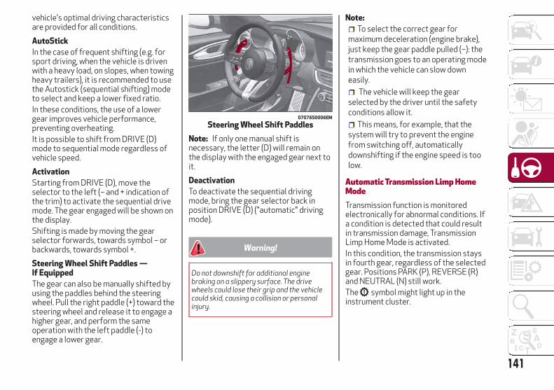
vehicle's optimal driving characteristicsare provided for all conditions.
AutoStick
In the case of frequent shifting (e.g. forsport driving, when the vehicle is drivenwith a heavy load, on slopes, when towingheavy trailers), it is recommended to usethe Autostick (sequential shifting) modeto select and keep a lower fixed ratio.In these conditions, the use of a lowergear improves vehicle performance,preventing overheating.It is possible to shift from DRIVE (D)mode to sequential mode regardless ofvehicle speed.
Activation
Starting from DRIVE (D), move theselector to the left (– and + indication ofthe trim) to activate the sequential drivemode. The gear engaged will be shown onthe display.Shifting is made by moving the gearselector forwards, towards symbol – orbackwards, towards symbol +.
Steering Wheel Shift Paddles —If Equipped
The gear can also be manually shifted byusing the paddles behind the steeringwheel. Pull the right paddle (+) toward thesteering wheel and release it to engage ahigher gear, and perform the sameoperation with the left paddle (-) toengage a lower gear.
Note: If only one manual shift isnecessary, the letter (D) will remain onthe display with the engaged gear next toit.
Deactivation
To deactivate the sequential drivingmode, bring the gear selector back inposition DRIVE (D) ("automatic" drivingmode).
Warning!
Do not downshift for additional enginebraking on a slippery surface. The drivewheels could lose their grip and the vehiclecould skid, causing a collision or personalinjury.
Note:
To select the correct gear formaximum deceleration (engine brake),just keep the gear paddle pulled (–): thetransmission goes to an operating modein which the vehicle can slow downeasily.
The vehicle will keep the gearselected by the driver until the safetyconditions allow it.
This means, for example, that thesystem will try to prevent the enginefrom switching off, automaticallydownshifting if the engine speed is toolow.
Automatic Transmission Limp HomeModeTransmission function is monitoredelectronically for abnormal conditions. Ifa condition is detected that could resultin transmission damage, TransmissionLimp Home Mode is activated.In this condition, the transmission staysin fourth gear, regardless of the selectedgear. Positions PARK (P), REVERSE (R)and NEUTRAL (N) still work.The symbol might light up in theinstrument cluster.
07076S0006EM
Steering Wheel Shift Paddles
141

Temporary failure
In the event of a momentary problem, thetransmission can be reset to regain allforward gears by performing thefollowing steps:
1. Stop the vehicle.
2. Shift the transmission into PARK (P),if possible. If not, shift the transmissionto NEUTRAL (N).
3. Push and hold the ignition until theengine turns OFF.
4. Wait for about 10 seconds, thenrestart the engine.
5. Shift into the desired gear range. Ifthe problem is no longer detected, thetransmission will return to normaloperation.
Note: Even if the transmission can bereset, we recommend that you visit yourauthorized dealer at your earliestpossible convenience. Your authorizeddealer has diagnostic equipment todetermine if the problem could reoccur. Ifthe transmission cannot be reset, serviceis required at your authorized dealer.
Brake/Transmission Shift InterlockSystemThis vehicle is equipped with a BrakeTransmission Shift Interlock system(BTSI) that holds the gear selector inPARK (P) unless the brakes are applied.This system prevents you from movingthe gear selector from position PARK (P)unless the brakes are applied.To shift the transmission out of PARK (P),the ignition must be cycled to the AVVmode (engine running or not) and thebrake pedal must be pressed.
Brake/Transmission Shift InterlockDisabling
Only if strictly necessary (e.g. pushing thevehicle, conveyor vehicle washingsystems) inhibit the automatic activationof PARK (P) mode when stopping theengine, or proceed as described below:
1. Vehicle at a standstill.
2. NEUTRAL (N) mode activated.
3. Push the ignition button for at leastthree seconds.
The automatic park brake engagementfunction when the engine is stopped canalso be deactivated on the Informationand Entertainment system by selectingthe following functions on the main menu:"Settings", "Driver Assistance" and"Automatic Parking Brake".
Important NotesFailure to comply with what is reportedbelow may damage the transmission:
Shift into PARK (P) mode only with thevehicle at a standstill.
Select REVERSE (R) mode, or passfrom REVERSE to another mode onlywith the vehicle at a standstill and engineidling.
Do not change between PARK (P),REVERSE (R), NEUTRAL (N) or DRIVE (D)modes with engine running at a speedabove idling.
Before activating any transmissionoperating mode, fully depress the brakepedal.
Note: The unexpected movement of thevehicle can injure the occupants orpeople nearby. Do not leave the vehiclewith engine running: before getting out ofthe passenger compartment alwaysengage the electric park brake, select thePARK (P) mode, stop the engine.
Warning!
It is dangerous to shift out of PARK orNEUTRAL if the engine speed is higher thanidle speed. If your foot is not firmly pressingthe brake pedal, the vehicle could accelerate
142
STA
RT
ING
AN
DO
PE
RAT
ING

quickly forward or in reverse. You could losecontrol of the vehicle and hit someone orsomething. Only shift into gear when theengine is idling normally and your foot isfirmly pressing the brake pedal.
Unintended movement of a vehicle couldinjure those in or near the vehicle. As with allvehicles, you should never exit a vehiclewhile the engine is running. Before exiting avehicle, always apply the park brake, shiftthe transmission into PARK, and turn theignition STOP/OFF. When the ignition is inthe STOP/OFF mode, the transmission islocked in PARK, securing the vehicle againstunwanted movement.
When leaving the vehicle, always makesure the ignition is in the STOP/OFF mode,remove the key fob from the vehicle, andlock the vehicle.
Never leave children alone in a vehicle, orwith access to an unlocked vehicle. Allowingchildren to be in a vehicle unattended isdangerous for a number of reasons. A childor others could be seriously or fatallyinjured. Children should be warned not totouch the parking brake, brake pedal or thetransmission gear selector.
Do not leave the key fob in or near thevehicle (or in a location accessible tochildren), and do not leave the ignition in theAVV or ON mode. A child could operatepower windows, other controls, or move thevehicle.
Caution!
Only engage the gear with engine at idlingwhile fully depressing the brake pedal. If thetransmission temperature exceeds thenormal operating limits, the transmissioncontrol unit may change the gearengagement order and reduce the drivetorque. If the transmission overheats, itcould operate incorrectly until it cools down.
When using the vehicle with extremelylow external temperatures, thetransmission operation may changedepending on the engine and transmissiontemperature, as well as vehicle speed.Activation of the torque converter clutchand of the eighth gear is inhibited until thetransmission oil is correctly warmed up.Complete operation of the transmission willbe enabled as soon as the fluid temperaturereaches the predefined value.
ALFA DNA SELECTORAlfa DNA SystemThis vehicle is equipped with an Alfa DNAsystem selector (located on the centerconsole). There are four modes ofoperation to be selected according todriving style and road conditions:
d = Dynamic (sports driving mode).
n = Natural (mode for driving in normalconditions).
a = Advanced Efficiency (ECO drivingmode for maximum fuel savings).
= Adjusts the calibration of theactive suspension (if equipped).
07076S0004BASE
Alfa DNA System Selector
143

The symbol of the active mode lights upin red on the selector.On the instrument panel display, thedifferent modes are characterized bydifferent colors:
Natural - Blue
Dynamic - Red
Advanced Efficiency - Green
Each driving mode is graphically differentin frame color and contents of eachindividual "performance" screen.
Driving Modes"Natural" Mode
“Natural” Mode is characterized byreduced engine performance and ECOshifting strategy for the automatictransmission.
Activation
It is activated by rotating the selector tothe letter "n", the displays light up in blue.
The "Performance" screen graphicallyreproduces some parameters closelylinked to the efficiency of the drivingstyle, with a view to limiting consumption.
"Dynamic" Mode
Activation
It is activated by rotating the selector tothe letter "d", the displays light up in red.
ESC and ASR systems: interventionthresholds that ensure more enjoyable,sportier driving while guaranteeing thestability of the vehicle.Engine and transmission: adoption ofsports mapping.
07076S0003EM
Mode Display
07116S0002EM
Natural Mode
07116S0001EM
Natural Mode Performance Display
07116S0003EM
Dynamic Mode
144
STA
RT
ING
AN
DO
PE
RAT
ING

Warning!
In "Dynamic", the sensitivity of theaccelerator pedal increases considerably.Consequently, driving is less fluid andcomfortable.
"Advanced Efficiency" Mode
Activation
It is activated by rotating the selector tothe letter "a", the displays light up in green.
ESC and ASR systems: interventionthresholds aimed at ensuring maximumsafety in low-grip driving conditions. It isadvisable to select "Advanced Efficiency"mode in the presence of low-grip roadsurfaces.Engine and transmission: standardresponse.The "Performance" screen graphicallydisplays some parameters closelyrelated to the vehicle consumption.
Driving Mode Deactivation
To deactivate any driving mode, simplymove the selector to any other mode.Note:
When the engine is next started, the"Advanced Efficiency", "Dynamic" and"Natural" mode selected previously isretained. The system will reactivate in"Advanced Efficiency", "Dynamic" or"Natural" mode, depending on whichmode was selected before the enginewas stopped.
When the engine is next started, the"Race" mode selected previously is notretained. The system will reactivate in"Dynamic" mode.
It is not possible to go directly from"Dynamic" mode to "AdvancedEfficiency" mode and vice versa. Youmust always activate the “Natural” modefirst and then select the other mode.
07116S0006EM
Dynamic Mode Performance Display
The "Performance" screen displaysparameters related to vehicle stability,the graphs illustrate the trend of thelongitudinal/lateral accelerations(G-meter information), consideringgravity acceleration as a reference unit.
Lateral acceleration peaks are displayedon the right.
07116S0005EM
Advanced Efficiency Mode
07116S0008EM
Advanced Efficiency Mode PerformanceDisplay
145

ALFA ACTIVE SUSPENSION(AAS) — IF EQUIPPEDThe vehicle's electronic suspensionsmanagement system is the result of asophisticated elaboration of the variousboard sensors, aimed at optimizing thevehicle's performance.The system continuously monitors thedamping of the suspensions through theactuator installed on each shockabsorber. This way, the calibration of theshock absorbers can be adjusted to theconditions of the road surface and to thedynamic conditions of the vehicle,improving its comfort and road holding.The driver can choose, even while driving,(only in "Dynamic” mode), between twotypes of suspension calibration: a moresporty or a more comfortable one.
By pressing the button, the systemprepares to work with a shock absorbercalibration which favours drivingcomfort.
In case of a system failure, the symboland a dedicated message will be
shown on the instrument panel display.
STOP/START SYSTEMStop/Start SystemThe Stop/Start system automaticallyshuts off the engine during a vehicle stopif the required conditions are met.Releasing the brake pedal or acceleratorpedal will automatically restart theengine.The function was developed to increasevehicle efficiency by reducing fuelconsumption, gas emissions, and soundpollution.
Operating ModeStopping the Engine
With vehicle at a standstill and brakepedal pressed, the engine switches off ifthe gear selector is in a position otherthan REVERSE (R).The system does not operate when thegear selector is in REVERSE (R), in orderto making parking maneuvers easier.In the event of stops uphill, engineswitching off is disabled to make the "HillStart Assist" function available (worksonly with running engine).
04306S0001BASE
“Alfa DNA” System Selector
146
STA
RT
ING
AN
DO
PE
RAT
ING

NOTE: The engine can only beautomatically stopped after having run atabout 6 mph (10 km/h). After anautomatic restart, the vehicle only needsto exceed a speed of 0.3 mph (0.5 km/h)to stop the engine.Engine stopping is signaled by the
symbol lighting up on the instrumentcluster display.
Restarting the Engine
To restart the engine, release the brakepedal.With brake pressed, if the gear selector isin automatic mode - DRIVE (D) - theengine can be restarted by moving thegear selector to REVERSE (R) orNEUTRAL (N) or "AutoStick".With brake pressed, if the gear selector isin "AutoStick" mode, the engine can berestarted by moving the gear selector to"+" or "–", or REVERSE (R) or NEUTRAL (N).When the engine has been stoppedautomatically, keeping the brake pedalpressed, the brake can be releasedkeeping the engine off by quickly shiftingthe gear selector to PARK (P).To restart the engine, just move the gearselector out of a position other thanPARK (P).
System Manual Activation/DeactivationTo manually activate/deactivate thesystem, push the button located in thecontrol panel on the left of the steeringwheel.
System Activation
The activation of the system is indicatedby the symbol lighting up on thedisplay. In this condition, the light on thebutton is off.
System Deactivation
A message will appear on the displaywhen the system is deactivated. In thiscondition, the light on the button is on.Note: Each time the engine is started,the system is activated regardless ofwhere was when it was previouslyswitched off.
Possible Reasons The Engine Does NotAutostopFor higher comfort and increased safety,and to reduce emissions, there arecertain conditions where the engine willnot autostop despite the system beingactive, such as:
Engine still cold.
Especially cold outside temperature.
Battery not sufficiently charged.
Driver's door not shut.
Driver's seat belt not fastened.
Reverse gear engaged (e.g. for parkingmaneuvers).
With the automatic climate controlactive, an adequate cabin heating orcooling comfort has not been reached orwith MAX-DEF function active.
During the first period of use, toinitialize the system.
Steering angle beyond threshold.
Engine Restarting ConditionsDue to comfort, emission control andsafety reasons, the engine can restartautomatically without any action by thedriver, under special conditions, such as:
Battery not sufficiently charged.
Reduced braking system vacuum (e.g.if the brake pedal is pressed repeatedly).
Vehicle moving (e.g. when driving onroads with a grade).
07126S0051EM
Stop/Start Button
147

Engine stopping by the Stop/Startsystem for more than approx. threeminutes.
With the automatic climate controlactive, an adjustment in cabin heating orcooling is made or with MAX-DEFfunction active.
Safety FunctionsWhen the engine is stopped through theStop/Start system, if the driver releasestheir seat belt, opens the driver's orpassenger's door, or opens the hood frominside the vehicle, the engine can berestarted only by using the ignition.This condition is indicated to the driverboth through a buzzer and a message onthe instrument cluster display.
Irregular OperationIn the event of malfunction, theStop/Start system is deactivated.For failure indications, see the "WarningLights and Messages" paragraph,"Getting To Know Your Instrument Panel"chapter.
Vehicle InactivityIn the event of vehicle inactivity (or if thebattery is replaced), special attentionmust be paid to the disconnection of thebattery power supply.
Proceed as follows:Remove connector from socket todisconnect sensor (battery statusmonitoring) installed on the negative poleof the battery. This sensor should neverbe disconnected from the pole except ifthe battery is replaced.
Note: After setting the ignition to STOPand having closed the driver side door,wait at least one minute beforedisconnecting the electrical supply fromthe battery. When reconnecting theelectrical supply to the battery, makesure that the ignition is in the STOP modeand the driver side door is closed.
SPEED LIMITERDescriptionThis feature allows the speed of thevehicle to be limited to speeds, which canbe set by the driver.The maximum speed can be set with thevehicle stationary or in motion. Theminimum speed that can be set is 18 mph(30mk/h).When this feature is active, the vehiclespeed depends on the pressing of theaccelerator pedal until the programmedspeed limit is reached (see "Speed LimitProgramming" paragraph).
Activating The DeviceThe feature can be activated/deactivated through the Information andEntertainment System.
Activating The Device
To access this feature on the main menu,select the following items in sequence:"Settings", "Safety", “Speed Limiter” and“ON”.The activation of this feature is signaledby the displaying of the green symbolalong with the last speed set. The SpeedLimiter feature can remain activeconcurrently with the Speed Controlsystem. If a speed limit below the oneindicated in the Speed Control isselected, the Speed Control speed will belowered to that of the Speed Limiter. Thisfunction remains available in RACE mode.
07126S0002EM
Battery Power Supply
1 — Socket2 — Sensor3 — Connector
148
STA
RT
ING
AN
DO
PE
RAT
ING
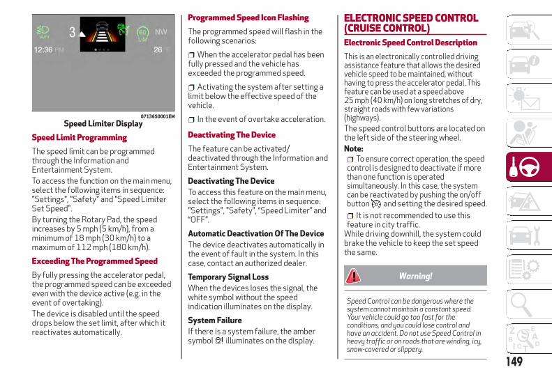
Speed Limit ProgrammingThe speed limit can be programmedthrough the Information andEntertainment System.To access the function on the main menu,select the following items in sequence:"Settings", "Safety" and "Speed LimiterSet Speed".By turning the Rotary Pad, the speedincreases by 5 mph (5 km/h), from aminimum of 18 mph (30 km/h) to amaximum of 112 mph (180 km/h).
Exceeding The Programmed SpeedBy fully pressing the accelerator pedal,the programmed speed can be exceededeven with the device active (e.g. in theevent of overtaking).The device is disabled until the speeddrops below the set limit, after which itreactivates automatically.
Programmed Speed Icon FlashingThe programmed speed will flash in thefollowing scenarios:
When the accelerator pedal has beenfully pressed and the vehicle hasexceeded the programmed speed.
Activating the system after setting alimit below the effective speed of thevehicle.
In the event of overtake acceleration.
Deactivating The DeviceThe feature can be activated/deactivated through the Information andEntertainment System.
Deactivating The Device
To access this feature on the main menu,select the following items in sequence:"Settings", "Safety", “Speed Limiter” and“OFF”.
Automatic Deactivation Of The Device
The device deactivates automatically inthe event of fault in the system. In thiscase, contact an authorized dealer.
Temporary Signal Loss
When the devices loses the signal, thewhite symbol without the speedindication illuminates on the display.
System Failure
If there is a system failure, the ambersymbol illuminates on the display.
ELECTRONIC SPEED CONTROL(CRUISE CONTROL)Electronic Speed Control DescriptionThis is an electronically controlled drivingassistance feature that allows the desiredvehicle speed to be maintained, withouthaving to press the accelerator pedal. Thisfeature can be used at a speed above25 mph (40 km/h) on long stretches of dry,straight roads with few variations(highways).The speed control buttons are located onthe left side of the steering wheel.Note:
To ensure correct operation, the speedcontrol is designed to deactivate if morethan one function is operatedsimultaneously. In this case, the systemcan be reactivated by pushing the on/offbutton and setting the desired speed.
It is not recommended to use thisfeature in city traffic.
While driving downhill, the system couldbrake the vehicle to keep the set speedthe same.
Warning!
Speed Control can be dangerous where thesystem cannot maintain a constant speed.Your vehicle could go too fast for theconditions, and you could lose control andhave an accident. Do not use Speed Control inheavy traffic or on roads that are winding, icy,snow-covered or slippery.
07136S0001EM
Speed Limiter Display
149

ActivatingTo activate the Electronic Speed ControlSystem, push the on/off button locationon the left side of the steering wheel.
The activation of the system is signaledby the white warning light illuminatingin the instrument cluster display.The Electronic Speed Control functioncan remain active at the same time as theSpeed Limiter System. If a speed limitbelow the one indicated in the set speedcontrol, the speed control speed will belowered to that of the Speed Limiter.Note: The system cannot be engaged inFIRST or REVERSE gear. It is advisable toengage it in THIRD gear or higher if usingthe Autostick feature.
Warning!
Leaving the Speed Control system on whennot in use is dangerous. You couldaccidentally set the system or cause it to gofaster than you want. You could lose controland have an accident. Always leave thesystem OFF when you are not using it.
Setting The Desired SpeedTo set a desired speed, proceed asfollows:
1. Turn the Electronic Speed Control on.
2. When the vehicle has reached thedesired speed, push the SET switch up ordown and release to activate. When theaccelerator is released, the vehicle willkeep the selected speed automatically.
If needed (when overtaking for instance),you can accelerate beyond the set speedby pressing the accelerator. When yourelease the pedal, the vehicle goes backto the previously set speed.When traveling downhill with the systemactive, the vehicle speed may slightlyexceed the set one.Note: Before pushing the SET switch, thevehicle must be traveling at a constantspeed on a flat surface.
Increasing/Decreasing SpeedIncreasing Speed
Once the Electronic Speed Control hasbeen activated, the speed can beincreased by pushing the SET switchupward.By keeping the button pushed, the setspeed will increase until the button isreleased. The new speed will then be set.At every movement of the SET switch,the set speed can be adjusted.
Decreasing Speed
When the feature is active, to reduce thespeed, push the SET switch downward.By keeping the button pushed, the setspeed will decrease until the button isreleased. The new speed will then be set.At every movement of the SET switch,the set speed can be adjusted.
07146S0001EM
Electronic Speed Control On/Off Switch
07146S0002EM
Set Switch Location
150
STA
RT
ING
AN
DO
PE
RAT
ING

Note: Moving the SET switch allows toadjust the speed according to theselected unit of measurement set on theInformation and Entertainment System(see dedicated supplement).
Accelerating When Overtaking
Press the accelerator as you wouldnormally. When the pedal is released, thevehicle will return to the set speed.
Use Of The Feature On Hilly Routes
The feature can automatically downshiftto keep the set speed when driving onhilly routes.On steep grades, the loss or gain in speedmay be considerable and is advisable todeactivate the Electronic Speed Control.Note: The feature keeps the speed seteven uphill and downhill. A slight variationin the speed on slight rises is completelynormal.
Recalling The SpeedNote: Before returning to the previouslyset speed, you must accelerate to aspeed close to that speed, then push theRES button and release it.
While in DRIVE (D), push and release theRES button to recall the previously setspeed.
In Autostick (sequential) mode, beforerecalling the previously set speed, youshould accelerate until you are close tothat speed. Then, push and release theRES button.
DeactivatingLightly pressing the brake pedaldeactivates the speed control withoutdeleting the set speed.The speed control may also bedeactivated by applying the electric parkbrake or when the braking system isoperated (e.g. operation of the ESCsystem).The set speed is deleted in the followingcases:
Pushing the on/off button twice.
The ignition is cycled to the STOPposition
If there is a malfunction with theElectronic Speed Control.
ADAPTIVE CRUISE CONTROL(ACC) — IF EQUIPPEDSystem DescriptionThe Adaptive Cruise Control (ACC) is adriver assist system that combines thespeed control functions for controllingthe distance from the vehicle ahead.The system allows to set and hold thevehicle at the desired speed withoutneeding to press the accelerator. It alsoallows to set and hold a distance from thevehicle ahead (these settings are set bythe driver).The Adaptive Cruise Control (ACC) uses aradar sensor located behind the frontbumper and a camera located in thecenter/upper part of the windshield, todetect the presence of a vehicle closeahead.
07146S0003EM
Resume Button Location
06016S0003EM
Front Bumper Radar Location
151
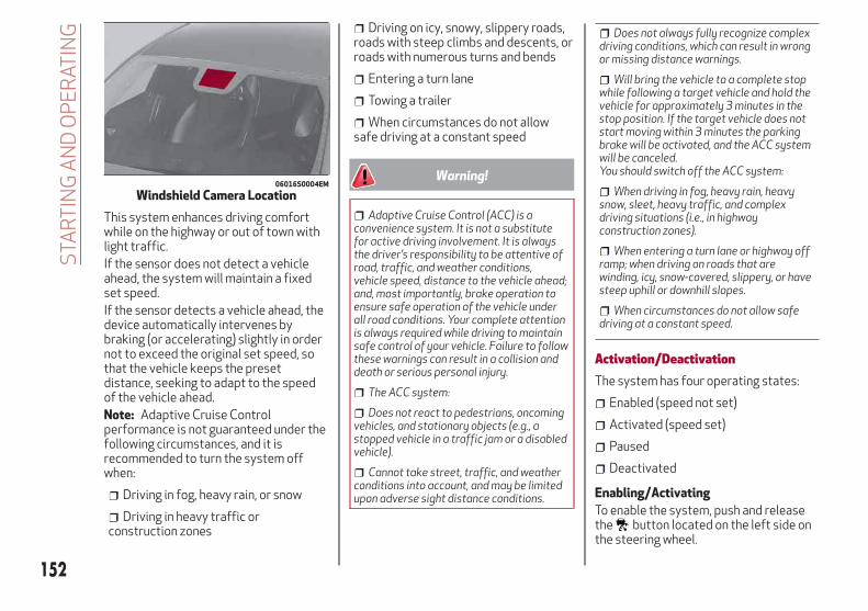
This system enhances driving comfortwhile on the highway or out of town withlight traffic.If the sensor does not detect a vehicleahead, the system will maintain a fixedset speed.If the sensor detects a vehicle ahead, thedevice automatically intervenes bybraking (or accelerating) slightly in ordernot to exceed the original set speed, sothat the vehicle keeps the presetdistance, seeking to adapt to the speedof the vehicle ahead.Note: Adaptive Cruise Controlperformance is not guaranteed under thefollowing circumstances, and it isrecommended to turn the system offwhen:
Driving in fog, heavy rain, or snow
Driving in heavy traffic orconstruction zones
Driving on icy, snowy, slippery roads,roads with steep climbs and descents, orroads with numerous turns and bends
Entering a turn lane
Towing a trailer
When circumstances do not allowsafe driving at a constant speed
Warning!
Adaptive Cruise Control (ACC) is aconvenience system. It is not a substitutefor active driving involvement. It is alwaysthe driver’s responsibility to be attentive ofroad, traffic, and weather conditions,vehicle speed, distance to the vehicle ahead;and, most importantly, brake operation toensure safe operation of the vehicle underall road conditions. Your complete attentionis always required while driving to maintainsafe control of your vehicle. Failure to followthese warnings can result in a collision anddeath or serious personal injury.
The ACC system:
Does not react to pedestrians, oncomingvehicles, and stationary objects (e.g., astopped vehicle in a traffic jam or a disabledvehicle).
Cannot take street, traffic, and weatherconditions into account, and may be limitedupon adverse sight distance conditions.
Does not always fully recognize complexdriving conditions, which can result in wrongor missing distance warnings.
Will bring the vehicle to a complete stopwhile following a target vehicle and hold thevehicle for approximately 3 minutes in thestop position. If the target vehicle does notstart moving within 3 minutes the parkingbrake will be activated, and the ACC systemwill be canceled.You should switch off the ACC system:
When driving in fog, heavy rain, heavysnow, sleet, heavy traffic, and complexdriving situations (i.e., in highwayconstruction zones).
When entering a turn lane or highway offramp; when driving on roads that arewinding, icy, snow-covered, slippery, or havesteep uphill or downhill slopes.
When circumstances do not allow safedriving at a constant speed.
Activation/DeactivationThe system has four operating states:
Enabled (speed not set)
Activated (speed set)
Paused
Deactivated
Enabling/Activating
To enable the system, push and releasethe button located on the left side onthe steering wheel.
06016S0004EM
Windshield Camera Location
152
STA
RT
ING
AN
DO
PE
RAT
ING

When the system is enabled and ready tooperate, the display shows the white iconabove dashes in place of the speed.
Setting a speed activates the system.The display shows the icon in green withthe set speed.
Warning!
Leaving the Adaptive Cruise Control (ACC)system on when not in use is dangerous. Youcould accidentally set the system or cause itto go faster than you want. You could losecontrol and have a collision. Always leavethe system off when you are not using it.
Pausing/Deactivating
With the feature enabled (speed not set),push the (on/off) button to disable.With the feature active (speed set), pushthe (on/off) button to pause. Thedisplay will show the icon in white withthe speed in brackets. To then deactivatethe feature, push the (on/off) buttonagain.
Setting The Desired SpeedThe speed can be set from a minimum of20 mph (30 km/h) to a maximum of110 mph (180 km/h).When the vehicle reaches the desiredspeed, push the SET switch upward ordownward and release it to activate thesystem. When the accelerator is released,the vehicle will maintain the set speedautomatically.
While the accelerator pedal is pressed,the system will not be able to control thedistance between the vehicle and the oneahead. In this case, the speed will bedetermined only by the position of theaccelerator pedal.The system will return to normaloperation as soon as the acceleratorpedal is released.The system cannot be set:
When pressing the brake pedal.
When the brakes are overheated.
When the electric park brake has beenoperated.
When either PARK (P), REVERSE (R) orNEUTRAL (N) is engaged.
When the engine rpm is above amaximum threshold.
When the vehicle speed is not withinthe operational speed range.
07146S0010EM
On/Off Button
07146S0016EM
Enabled Icons
07146S0017EM
SET Switch
153

When the ESC (or ABS or otherstability control systems) are operatingor have just operated.
When the ESC system is off.
When the Forward Collision Warningsystem (if equipped) is brakingautomatically.
In the event of system failure.
When the engine is OFF.
In case of obstruction of the radarsensor (in this case the bumper areawhere it is located must be cleaned).
If the system is set, the conditionsdescribed above also cause acancellation or deactivation of thesystem. These situations may varyaccording to the conditions.Note: The system will not be deactivatedwhen speeds higher than those set arereached by pressing the acceleratorpedal above 110 mph (180 km/h). Inthese situations, the system may notwork correctly and it is recommended todeactivate it.
To Vary The Speed SettingIncreasing Speed
Once the system has been activated, youcan increase the speed by lifting the SETswitch. Each time it is operated, thespeed increases by 1 mph.
By holding the button up, the set speedwill increase in increments of 5 mph untilthe button is released. Then, the newspeed will be set.
Decreasing Speed
Once the system has been activated, youcan decrease the speed by lowering theSET switch. Each time it is operated, thespeed decreases by 1 mph.By holding the button down, the setspeed will decrease in increments of5 mph until the button is released. Then,the new speed will be set.
Note:
Moving the SET switch allows you toadjust the speed according to theselected unit of measurement ("US" or"metric") set on the Information andEntertainment System (see dedicatedsupplement)
When the unit of measurement is setto metric, holding the SET switch thespeed will change in 10 km/h increments
By keeping the accelerator pedaldepressed, the vehicle can continue toaccelerate beyond the set speed. In thiscase, use the SET switch to set thespeed to the vehicle’s current speed
When you push the SET button toreduce the speed, the braking systemintervenes automatically if the enginebrake does not slow the vehicle downsufficiently to reach the set speed. Thedevice holds the set speed uphill anddownhill; however a slight variation isentirely normal, particularly on slightinclines
The transmission could change to alower gear when driving downhill, orwhen accelerating. This is normal andnecessary to maintain the set speed
The system will disable while drivingif the brakes overheat
Accelerating When OvertakingWhen driving with ACC activated andfollowing a vehicle, the system willprovide an additional acceleration up tothe ACC set speed to assist in passing thevehicle. This additional acceleration istriggered when the driver utilizes the leftturn signal and will only be active whenpassing on the left hand side.The system detects the direction oftraffic automatically when the vehiclepasses from left-hand traffic toright-hand traffic. In this case, theovertaking assist function is only activewhen the reference vehicle is overtakenon the right. The additional accelerationis deactivated when the driver uses theright direction indicator and returns tothe original lane.
154
STA
RT
ING
AN
DO
PE
RAT
ING

Resuming The SpeedOnce the system has been canceled butnot deactivated, to resume a previouslyset speed, simply push the RES button andremove your foot from the accelerator torecall it.The system will be set to the last storedspeed.
Before returning to the previously setspeed, bring the speed close to that value,then push the RES button and release it.
Warning!
The Resume function should only be used iftraffic and road conditions permit. Resuminga set speed that is too high or too low forprevailing traffic and road conditions couldcause the vehicle to accelerate or deceleratetoo sharply for safe operation. Failure tofollow these warnings can result in a collisionand death or serious personal injury.
Setting The Distance Between VehiclesThe distance between your vehicle andthe vehicle ahead may be set to one bar(short), two bars (medium), three bars(long), or four bars (maximum).
The distances from the vehicle ahead areproportional to speed.The interval of time with relation to thevehicle ahead remains constant andvaries from one second (for the shortdistance one-bar setting) to two seconds(for the maximum distance four-barsetting).The set distance is shown on the displayby a dedicated icon.The setting is four (maximum) the firsttime the system is used. After thedistance has been modified by the driver,the new distance will be stored also afterthe system is deactivated andreactivated.
To Decrease The Distance
Push and release the distance button todecrease the distance setting. Thedistance setting decreases by one bar(shorter) every time the button is pushed.
The set speed is held if there are novehicles ahead. Once the shortestdistance has been selected, the next pushof the button will set the maximumdistance.If a slower vehicle is detected in the samelane, the vehicle icon on the displayilluminates from grey to white. Thesystem automatically adjusts thevehicle’s speed to keep the set distance,independently of the set speed.The vehicle holds the set distance until:
The vehicle ahead accelerates to aspeed higher than the set speed.
The vehicle ahead leaves the lane orthe detection field of the Adaptive CruiseControl system sensor.
07146S0018EM
RES (Resume) Button
07146S0019EM
Distance Icons
07146S0015EM
Distance Button
155

The distance setting is changed.
The Adaptive Cruise Control system isdeactivated/paused.
Warning!
The maximum breaking applied by thesystem is limited. The driver may apply thebrakes in all cases if needed.
If the system predicts that the brakinglevel is insufficient to hold the set distance,either “BRAKE!” or a dedicated message isdisplayed to warn the driver of approachingthe vehicle ahead. An acoustic signal is alsoemitted. In this case, it is advised to brakeimmediately as necessary to hold a safedistance from the vehicle ahead.
The driver is responsible for ensuring thatthere are no pedestrians, other vehicles orobjectives along the direction of the vehicle.Failure to comply with these precautionsmay cause serious accidents and injuries.
The driver is fully responsible for holdinga safe distance from the vehicle aheadrespecting the highway code in force in therespective country.
“Stop And Go” FunctionThe “Stop and Go” operating strategyallows you to maintain a safe distancefrom the vehicle ahead until the vehiclehas completely stopped. It will also
restart the vehicle automatically if thevehicle ahead drives away within twoseconds, otherwise it is necessary topress the accelerator pedal or push theRES button to restart.
Warning!
When the ACC system is resumed, the drivermust ensure that there are no pedestrians,vehicles or objects in the path of the vehicle.Failure to follow these warnings can result ina collision and death or serious personalinjury.
DeactivationThe system is deactivated and the setspeed is canceled if:
The (on/off) button is pushed(when the system is on or paused).
The ignition is cycled to STOP.
The system is canceled (the set speedand distance are stored):
When the system is paused (Refer tothe “Activation / Deactivation” section).
When the conditions shown in the“Setting The Desired Speed” sectionoccur.
Limited Operation WarningIf the dedicated message is shown on thedisplay, a condition limiting the AdaptiveCruise Control operation may haveoccurred.This could be due to an obstruction of thevehicle’s sensor or camera. It could alsobe due to a fault in the system. If anobstruction is detected, clean the area ofthe windshield opposite the interior rearview mirror, where the camera is located,as well as the area of the front bumperwhere the sensor is located. Then checkthat the message has disappeared.When the conditions limiting the systemfunctions end, normal operation willresume.Should the fault persist, contact anauthorized dealer.
Precautions While DrivingThe system may not work correctly insome driving conditions (see below). Thedriver must control the vehicle at alltimes.
Vehicle Not Aligned
The system may not detect a vehicletraveling in the same lane, in the samedirection, but is not aligned. It also maynot detect a vehicle which is cutting infrom a side lane. Sufficient distance fromthe vehicles ahead may not beguaranteed in these cases.
156
STA
RT
ING
AN
DO
PE
RAT
ING
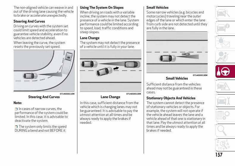
The non-aligned vehicle can weave in andout of the driving lane causing the vehicleto brake or accelerate unexpectedly.
Steering And Curves
Driving on curves with the system setcould limit speed and acceleration toguarantee vehicle stability, even if novehicles are detected ahead.When leaving the curve, the systemresets the previously set speed.
Note:
In cases of narrow curves, theperformance of the system could belimited. In this case, it is advisable todeactivate the system.
The system only limits the speedDURING a bend and not BEFORE it.
Using The System On Slopes
When driving on roads with a variableincline, the system may not detect thepresence of a vehicle in the lane. Systemperformance could be limited accordingto speed, load, traffic conditions andsteep slopes.
Lane Change
The system may not detect the presenceof a vehicle until it is fully in your lane.
In this case, sufficient distance from thevehicle which is changing lanes may notbe guaranteed. It is advisable to pay theutmost attention at all times and bealways ready to apply the brakes ifneeded.
Small Vehicles
Some narrow vehicles (e.g. bicycles andmotorcycles) traveling near the outeredges of the lane or which enter the lanefrom curb side are not detected until theyare fully in the lane.
Sufficient distance from the vehiclesahead may not be guaranteed in thesecases.
Stationary Objects And Vehicles
The system cannot detect the presenceof stationary vehicles or objects. Forexample, the system will not operate ifthe vehicle ahead leaves the lane and avehicle ahead of that one is stationary inthat lane. Pay the utmost attention at alltimes and be always ready to apply thebrakes if needed.
07146S0011EM
Steering And Curves07146S0012EM
Lane Change
07146S0013EM
Small Vehicles
157

Objects And Vehicles Moving InOpposite Or Crosswise Direction
The system cannot detect the presenceof objects or vehicles traveling inopposite or crosswise directions andconsequently will not activate.
General InformationThis vehicle has systems that operate onradio frequency that comply with Part15 of the Federal CommunicationsCommission (FCC) rules and withIndustry Canada Standards RSS-GEN/210/220/310.Operation is subject to the following twoconditions:
1. The device may not cause harmfulinterference.
2. The device must accept anyinterference received, includinginterference that may cause undesiredoperation of the device.
Changes or modifications to any of thesesystems by other than an authorizedservice facility could void authorizationto use this equipment.
PARK SENSORS SYSTEMVehicles With Rear Sensors OnlyThe parking sensors, located in the rearbumper, detect obstacles while thevehicle is in REVERSE. When an obstacleis detected, an acoustic alert will soundand visual indications will be displayed onthe instrument cluster.
Engagement/Disengagement
To turn the system off, push the ParkSensors System button located to theleft of the headlight switch. The indicatorlight within the button will illuminatewhen the system is turned off. Pushingthe button a second time will turn thesystem back on, and the indicator lightwill turn off.
07146S0014EM
Objects And Vehicles Moving InOpposite Or Crosswise Direction
07176S0001EM
Rear Sensor Location
158
STA
RT
ING
AN
DO
PE
RAT
ING

The indicator light within the ParkSensors System switch will also be on incase of system failure. If the switch ispushed with a system failure, theindicator light will flash forapproximately five seconds. The light willthen stay on constantly.Note: When the ignition is cycled to ON,the Park Sensors System keeps the laststate when the engine was stopped(activated or deactivated) in its memory.
System Activation/Deactivation
The system, when engaged, isautomatically activated by engaging theREVERSE gear. It is deactivated byengaging another gear.
Acoustic Signal
When REVERSE is engaged and there isan obstacle behind the vehicle, anacoustic signal with variable frequencywill sound.
The acoustic signal increases infrequency as the distance between thevehicle and the obstacle decreases.
The acoustic signal becomescontinuous when the distance betweenthe vehicle and the obstacle is less than11 inches (30 cm), and stops if thedistance increases.
The acoustic signal is constant if thedistance between the vehicle and theobstacle is unchanged.
Note: If several obstacles are detectedby the sensors, only the nearest one isconsidered.
Indication On Display
The driver can select the type of warningthey would like to be displayed throughthe Information and EntertainmentSystem. To access the function on themain menu, select in the following order:
1. “Settings.”
2. “Driver Assistance.”
3. “ParkSense.”
4. “Mode.”
5. “Sound-Display.”
Visual Indications
The system indicates the presence of anobstacle by displaying a single red arc inthe detected area, in relation to thedistance of the object and the position ofthe vehicle.
If the obstacle is detected in the rearcentral area, a single red arc will bedisplayed as the obstacle approaches,first constant, then flashing, in additionto an acoustic signal.If the obstacle is detected in the rear leftand/or right area, a single red flashing arcwill be shown in the corresponding areaon the display and the system will emit anacoustic signal, either at frequentintervals or constantly.In general, the vehicle is closer to theobstacle when a single red flashing arc isshown on the display and the acousticsignal becomes continuous.If several obstacles are detectedsimultaneously in the rear area, thedisplay will show all of them, regardlessof the area in which they were detected.It is not possible to exit from the displayscreen while the vehicle is in REVERSE.
Fault Indication
Parking sensor faults, if any, will beindicated when REVERSE is engaged by amessage on the instrument clusterdisplay. Refer to "Warning Lights AndMessages" in "Getting To Know YourInstrument Panel" for furtherinformation.
07176S0052EM
Park Sensors System On/Off Switch
159

Messages On The Display
In case of system failure, a dedicatedmessage appears on the instrumentcluster for about five seconds.
Cleaning The Front Sensors: If thedisplay shows a message requiring thesensors to be cleaned, make sure that theouter surface and the underside of therear bumper is free of debris (e.g. snow,mud, ice, etc.). Once these areas are clear,cycle the ignition to the STOP position.Then, return it to ON position. If themessage is still displayed, contact anauthorized dealer.
Audio System Not Available: If thedisplay shows a message that the audiosystem is not available, it means that theacoustic signal will be emitted by theinstrument panel, and not through thevehicles speakers.
Note: Some conditions may influencethe performance of the Park SensorsSystem:
Reduced sensor sensitivity could bedue to the presence of ice, snow, mud, orthick paint on the surface of the sensor.
The sensors may detect a falseobstacle (echo interference) due tomechanical interference, for examplewhen washing the vehicle or in extremeweather.
The signals sent by the sensors canbe altered by the presence of ultrasonicsystems (e.g. pneumatic brake systemsof trucks or pneumatic drills) near thevehicle.
System performance can beinfluenced by the position of thesensors. For example, due to a change inthe ride setting (caused by wear to theshock absorbers or suspension), bychanging tires, overloading the vehicle oroperations that require the vehicle to belowered.
Be sure not to place bumper stickersor other adhesives over the sensors asthis will affect system performance.
Warning!
Drivers must be careful when backing upeven when using the Parking Sensor system.Always check carefully behind your vehicle,and be sure to check for pedestrians,animals, other vehicles, obstructions, orblind spots before backing up. You areresponsible for the safety of yoursurroundings and must continue to payattention while backing up. Failure to do socan result in serious injury or death.
Caution!
The Parking Sensor system is only aparking aid and it is unable to recognizeevery obstacle, including small obstacles.Parking curbs might be temporarilydetected or not detected at all. Obstacleslocated above or below the sensors will notbe detected when they are in closeproximity
The vehicle must be driven slowly whenusing the Parking Sensor system in order tobe able to stop in time when an obstacle isdetected. It is recommended that the driverlooks over his/her shoulder when using theParking Sensor system.
160
STA
RT
ING
AN
DO
PE
RAT
ING
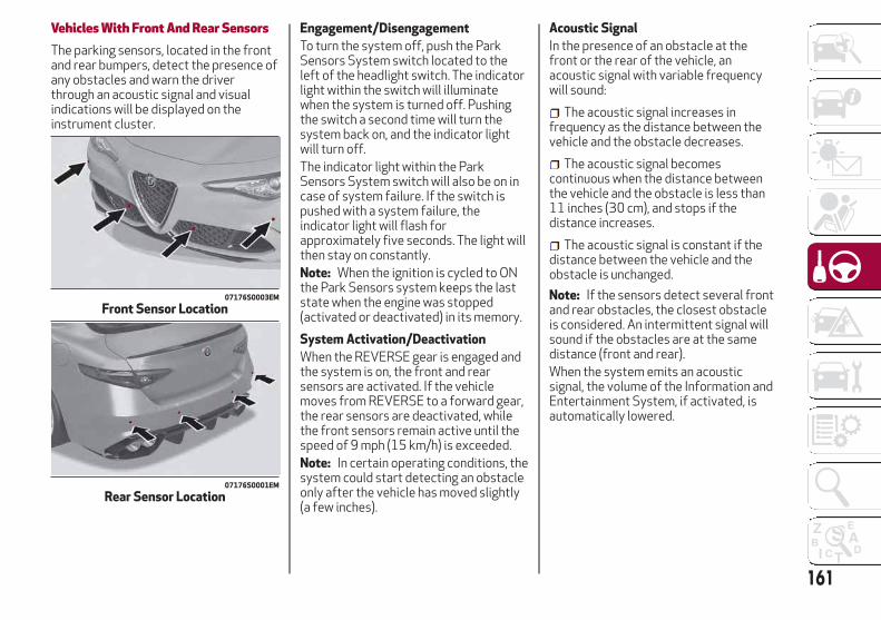
Vehicles With Front And Rear SensorsThe parking sensors, located in the frontand rear bumpers, detect the presence ofany obstacles and warn the driverthrough an acoustic signal and visualindications will be displayed on theinstrument cluster.
Engagement/Disengagement
To turn the system off, push the ParkSensors System switch located to theleft of the headlight switch. The indicatorlight within the switch will illuminatewhen the system is turned off. Pushingthe switch a second time will turn thesystem back on, and the indicator lightwill turn off.The indicator light within the ParkSensors System switch will also be on incase of system failure. If the switch ispushed with a system failure, theindicator light will flash forapproximately five seconds. The light willthen stay on constantly.Note: When the ignition is cycled to ONthe Park Sensors system keeps the laststate when the engine was stopped(activated or deactivated) in its memory.
System Activation/Deactivation
When the REVERSE gear is engaged andthe system is on, the front and rearsensors are activated. If the vehiclemoves from REVERSE to a forward gear,the rear sensors are deactivated, whilethe front sensors remain active until thespeed of 9 mph (15 km/h) is exceeded.Note: In certain operating conditions, thesystem could start detecting an obstacleonly after the vehicle has moved slightly(a few inches).
Acoustic Signal
In the presence of an obstacle at thefront or the rear of the vehicle, anacoustic signal with variable frequencywill sound:
The acoustic signal increases infrequency as the distance between thevehicle and the obstacle decreases.
The acoustic signal becomescontinuous when the distance betweenthe vehicle and the obstacle is less than11 inches (30 cm), and stops if thedistance increases.
The acoustic signal is constant if thedistance between the vehicle and theobstacle is unchanged.
Note: If the sensors detect several frontand rear obstacles, the closest obstacleis considered. An intermittent signal willsound if the obstacles are at the samedistance (front and rear).When the system emits an acousticsignal, the volume of the Information andEntertainment System, if activated, isautomatically lowered.
07176S0003EM
Front Sensor Location
07176S0001EM
Rear Sensor Location
161

Indication On Display
The driver can select the type of warningthey would like to be displayed throughthe Information and EntertainmentSystem. To access the function on themain menu, select in the following order:
1. “Settings.”
2. “Driver Assistance.”
3. “ParkSense.”
4. “Mode.”
5. “Sound-Display.”
Visual Indications
The system indicates the presence of anobstacle by displaying a single red arc inthe detected areas, in relation to thedistance of the object and the position ofthe vehicle.If the obstacle is detected in the front orrear central area, a single red arc will bedisplayed as the obstacle approaches,first constant, then flashing, in additionto an acoustic signal.If the obstacle is detected in the front orrear left and/or right area, a single redflashing arc will be shown in thecorresponding area on the display andthe system will emit an acoustic signal,either at frequent intervals or constantly.If several obstacles are detectedsimultaneously in the front and rear area,the display will show all of them,regardless of the area in which they weredetected.
In general, the vehicle is closer to theobstacle when a single or several flashingarcs are shown on the display and theacoustic signal becomes continuous.It is not possible to exit from the displayscreen while the vehicle is in REVERSE.
Fault Indication
Parking sensor faults, if any, will beindicated by a message on the display onthe instrument cluster. Refer to "WarningLights And Messages" in "Getting ToKnow Your Instrument Panel" for furtherinformation.
Messages On The Display
In case of system failure, a dedicatedmessage appears on the instrumentcluster for about five seconds.
Cleaning The Front Or Rear Sensors:If the display shows a message requiringthe sensors to be cleaned, make sure thatthe outer surface and the underside ofthe front and rear bumpers are free ofdebris (e.g. snow, mud, ice, etc.). Oncethese areas are clear, place the ignition inSTOP mode. Then, return it to ON mode.If the message is still displayed, contactan authorized dealer.
Audio System Not Available: If thedisplay shows a message that the audiosystem is not available, it means that theacoustic signal will be emitted by theinstrument panel, and not through thevehicles speakers.
Note: Some conditions may influencethe performance of the Park SensorsSystem:
Reduced sensor sensitivity could bedue to the presence of ice, snow, mud, orthick paint on the surface of the sensor.
The sensors may detect a falseobstacle (echo interference) due tomechanical interference, for examplewhen washing the vehicle or in extremeweather.
The signals sent by the sensors canbe altered by the presence of ultrasonicsystems (e.g. pneumatic brake systemsof trucks or pneumatic drills) near thevehicle.
System performance can beinfluenced by the position of thesensors. For example, due to a change inthe ride setting (caused by wear to theshock absorbers or suspension), bychanging tires, overloading the vehicle oroperations that require the vehicle to belowered.
Be sure not to place bumper stickersor other adhesives over the sensors asthis will affect system performance.
162
STA
RT
ING
AN
DO
PE
RAT
ING
Warning!
Drivers must be careful when backing upeven when using the Parking Sensor system.Always check carefully behind your vehicle,and be sure to check for pedestrians,animals, other vehicles, obstructions, orblind spots before backing up. You areresponsible for the safety of yoursurroundings and must continue to payattention while backing up. Failure to do socan result in serious injury or death.
Caution!
The Parking Sensor system is only aparking aid and it is unable to recognizeevery obstacle, including small obstacles.Parking curbs might be temporarilydetected or not detected at all. Obstacleslocated above or below the sensors will notbe detected when they are in closeproximity
The vehicle must be driven slowly whenusing the Parking Sensor system in order tobe able to stop in time when an obstacle isdetected. It is recommended that the driverlooks over his/her shoulder when using theParking Sensor system.
LANE DEPARTURE WARNING(LDW) SYSTEMDescriptionThe Lane Departure Warning system usesa forward looking camera located on thewindshield to detect lane markings andmeasure vehicle position within the laneboundaries.When one or both lane limits aredetected and the vehicle passes over onewithout an activated turn signal, thesystem emits a visual as well as anacoustic signal.If the vehicle continues to go beyond theline of the lane without any interventionfrom the driver, the surpassed line willlight up on the display (left or right) tourge the driver to bring the vehicle backinto the limits of the lane.
Caution!
Do not tamper with nor operate on thecamera. Do not close the openings in theaesthetic cover located under the interiorrear view mirror. In the event of a failure ofthe camera, contact your authorized dealer.
The camera may have limited or absentoperation due to weather conditions suchas: heavy rain, hail, thick fog, heavy snow,formation of ice layers on the windshield.
Camera operation may also becompromised by the presence of dust,condensation, dirt or ice on the windshield,by traffic conditions (e.g. vehicles that aredriving not aligned with yours, vehicledriving in a transverse or opposite way onthe same lane, bend with a small radius ofcurvature), by road surface conditions andby driving conditions (e.g. off-road driving).Make sure the windshield is always clean.Use specific detergents and clean cloths toavoid scratching the windshield. The cameraoperation may also be limited or absent insome driving, traffic and road surfaceconditions.
If the windshield must be replaced due toscratches, chipping or breakage, contactexclusively your authorized dealer. Do notreplace the windshield on your own. It isadvisable to replace the windshield if it isdamaged in the area of the camera.
163

System Activation/DeactivationThe system is activated/deactivated bypushing the button located on the end ofthe multifunction lever.
Note: When the engine is started, thesystem maintains the operating modethat was selected when it was turnedOFF.
Activation Conditions
Once turned on, the system becomesactive only if the following conditions aremet:
The vehicle speed is above 37 mph(60 km/h).
The lane limit lines are visible at leaston one side.
There are suitable visibility conditions.
The road is straight or with wide radiusbends.
A suitable distance is kept from thevehicle in front.
The turn signal is not active.
Symbols And Messages On The DisplayThe Lane Departure Warning systemadvises the driver when the vehicleleaves the driving lane by showingsymbols and messages on the instrumentcluster display.
When the system is active and the lanelimits have not been detected, the displayshows a grey vehicle icon with two greylines.
Exiting A Lane With Detection Of ASingle Limit
When the system is active and only, forexample, the left lane limit has beendetected, the detected lane illuminates inwhite on the display; the system is readyto provide visual warnings on the displayin the event of unintentional exiting ofthe lane (turn signal not activated) to theleft.
07226S0001EM
Lane Departure Warning SystemActivation/Deactivation Button
07226S0002EM
Vehicle Changing Lanes
07226S0007EM
Lane Limits Not Detected
07226S0003EM
Left Lane Limit Detected
164
STA
RT
ING
AN
DO
PE
RAT
ING
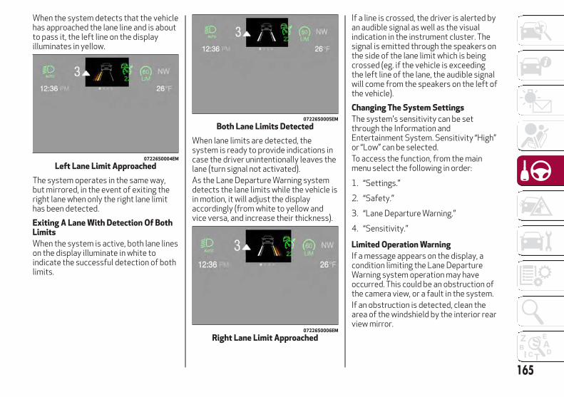
When the system detects that the vehiclehas approached the lane line and is aboutto pass it, the left line on the displayilluminates in yellow.
The system operates in the same way,but mirrored, in the event of exiting theright lane when only the right lane limithas been detected.
Exiting A Lane With Detection Of BothLimits
When the system is active, both lane lineson the display illuminate in white toindicate the successful detection of bothlimits.
When lane limits are detected, thesystem is ready to provide indications incase the driver unintentionally leaves thelane (turn signal not activated).As the Lane Departure Warning systemdetects the lane limits while the vehicle isin motion, it will adjust the displayaccordingly (from white to yellow andvice versa, and increase their thickness).
If a line is crossed, the driver is alerted byan audible signal as well as the visualindication in the instrument cluster. Thesignal is emitted through the speakers onthe side of the lane limit which is beingcrossed (eg. if the vehicle is exceedingthe left line of the lane, the audible signalwill come from the speakers on the left ofthe vehicle).
Changing The System Settings
The system's sensitivity can be setthrough the Information andEntertainment System. Sensitivity “High”or “Low” can be selected.To access the function, from the mainmenu select the following in order:
1. “Settings.”
2. “Safety.”
3. “Lane Departure Warning.”
4. “Sensitivity.”
Limited Operation Warning
If a message appears on the display, acondition limiting the Lane DepartureWarning system operation may haveoccurred. This could be an obstruction ofthe camera view, or a fault in the system.If an obstruction is detected, clean thearea of the windshield by the interior rearview mirror.
07226S0004EM
Left Lane Limit Approached
07226S0005EM
Both Lane Limits Detected
07226S0006EM
Right Lane Limit Approached
165

Although the vehicle can still be driven innormal conditions, the system may notfunction properly.When the conditions limiting the systemare corrected, it will go back to normaloperation. Should a fault persist, contactan authorized dealer.
System Failure Warning
If the system turns off and appears onthe display, it means that there is asystem fault.In this case, it is still possible to drive thevehicle, but you are advised to contact anauthorized dealer as soon as possible.
REAR BACK-UP CAMERA /DYNAMIC GRIDLINESDescriptionThe Rear Back-Up Camera is located justunder the vehicle’s trunk lid, above therear license plate.
When the vehicle is in REVERSE, theInformation and Entertainment Systemdisplay will show the area behind thevehicle, as seen by the Rear Back-upCamera, along with a warning message.
Rear Back-Up Camera Features
To activate the Rear Back-Up Camerafeatures, select “Settings” from the MainMenu of the Information andEntertainment System. Under “DriverAssistance”, Rear Back-Up Camerafeatures can be selected:
View
Camera Delay
Camera Guidelines
Selecting “View” will activate the cameraview on the display.Selecting “Camera Delay” will allow thecamera view to remain on the displayshortly after the vehicle is no longer inREVERSE, followed by the previouslyactive screen.
07186S0001EM
Rear Back-Up Camera Location
07186S0002EM
Rear Back-Up Camera Display
166
STA
RT
ING
AN
DO
PE
RAT
ING

Selecting “Camera Guidelines” willactivate the display of the dynamicguidelines that indicate the route of thevehicle.
Warning!
Drivers must be careful when backing upeven when using the Rear Back Up Camera.Always check carefully behind your vehicle,and be sure to check for pedestrians,animals, other vehicles, obstructions, orblind spots before backing up. You areresponsible for the safety of yoursurroundings and must continue to payattention while backing up. Failure to do socan result in serious injury or death.
Caution!
To avoid vehicle damage, Rear Back UpCamera should only be used as a parkingaid. The Rear Back Up Camera is unable toview every obstacle or object in your drivepath.
To avoid vehicle damage, the vehicle mustbe driven slowly when using the Rear BackUp Camera to be able to stop in time whenan obstacle is seen. It is recommended thatthe driver look frequently over his/hershoulder when using the Rear Back UpCamera.
Symbols And Messages On The DisplayIndications On The Display
Through the Information andEntertainment System settings, byactivating the "Camera Guidelines"feature, guidelines can be seen on therear camera display. If activated, theguidelines are positioned on the image tohighlight the width of the vehicle and theexpected reverse path based on thesteering wheel position.A superimposed central line indicates thecenter of the vehicle to assist in rearparking maneuvers. The various coloredareas indicate the distance from the rearof the vehicle.The table below shows the approximatedistances for each area:
AreaDistance from the rear
of the vehicle
Red0–11.8 inches
(0–30 cm)
Yellow11.8 inches to 3.3 feet
(30 cm–1 m)
Green3.3 feet or more
(1 m or more)
Messages On The Display
If the trunk lid is lifted, the camera willnot detect any obstacle behind thevehicle. The display will show a dedicatedwarning message.Make sure the trunk lid is closed bypushing next to the lock until it clicks.
Important NotesIce, snow or mud on the surface of the
camera may reduce its sensitivity. It isimportant to keep the camera surfaceclean, and free from debris.
When parking, be aware of obstaclesthat may be above or under the camerarange.
167

REFUELING THE VEHICLERefueling The VehicleBefore refueling, make sure that the fueltype is correct.Also, stop the engine before refueling.Note: An inefficient catalytic converterleads to harmful exhaust emissions, thuscontributing to air pollution.
Caution!
Never introduce leaded fuel to the tank,even in small amounts in an emergency, asthis would damage the catalytic converterbeyond repair.
Refueling CapacityTo ensure that you fill the tankcompletely, top off twice after the firstclick of the fuel nozzle.Further top-off could cause faults in thefuel feeding system.
Refueling ProcedureThe fuel filler door is unlocked when thecentral door locking system is unlocked.It is automatically locked when thecentral locking system is applied.
Opening The Fuel Filler Door
To refuel proceed as follows:
1. Open fuel filler door by pressing onthe point shown by the arrow.
2. Remove the fuel filler cap.
3. Insert the fuel nozzle fully into thefiller pipe.
4. When the fuel nozzle “clicks” or shutsoff, before removing the nozzle, wait forat least 10 seconds in order for the fuelto flow inside the tank.
5. Remove the fuel filler nozzle, tightenthe gas cap about ¼ turn until you hearone click. This is an indication that cap isproperly tightened.
The label indicates the fuel type(UNLEADED FUEL = gasoline).
Emergency Fuel Door Opening
In the event of an emergency the fuelfiller door can be opened by operatingfrom inside the trunk.Proceed as follows:
1. Open the trunk and locate theemergency fuel filler release cap on theinside lining.
2. Open the cap, and pull the cord insideto unlock the fuel filler door.
3. Open the fuel filler door by pressingon it (see the previous instructions).
07206S0001EM
Fuel Door
07206S0002EM
Fuel Door Label
168
STA
RT
ING
AN
DO
PE
RAT
ING

Warning!
Never have any smoking materials lit in ornear the vehicle when the fuel door is openor the tank is being filled.
Never add fuel when the engine is running.This is in violation of most state and federalfire regulations and may cause the MIL toturn on.
A fire may result if gasoline is pumpedinto a portable container that is inside of avehicle. You could be burned. Always placegas containers on the ground while filling.
Note: If the filler compartment iswashed with a pressure washer, keep it ata distance of at least 8 inches (20 cm).
VEHICLE LOADINGCertification LabelAs required by National Highway TrafficSafety Administration regulations, yourvehicle has a certification label affixed tothe driver's side door or pillar.This label contains the month and year ofmanufacture, Gross Vehicle WeightRating (GVWR), Gross Axle Weight Rating(GAWR) front and rear, and VehicleIdentification Number (VIN). AMonth-Day-Hour (MDH) number isincluded on this label and indicates theMonth, Day and Hour of manufacture. Thebar code that appears on the bottom ofthe label is your VIN.
Gross Vehicle Weight Rating(GVWR)
The GVWR is the total permissibleweight of your vehicle including driver,passengers, vehicle, options and cargo.The label also specifies maximumcapacities of front and rear axle systems(GAWR). Total load must be limited soGVWR and front and rear GAWR are notexceeded.
Payload
The payload of a vehicle is defined as theallowable load weight a truck can carry,including the weight of the driver, allpassengers, options and cargo.
Gross Axle Weight Rating (GAWR)
The GAWR is the maximum permissibleload on the front and rear axles. The loadmust be distributed in the cargo area sothat the GAWR of each axle is notexceeded.Each axle GAWR is determined by thecomponents in the system with thelowest load carrying capacity (axle,springs, tires or wheels). Heavier axles orsuspension components sometimesspecified by purchasers for increaseddurability does not necessarily increasethe vehicle's GVWR.
Tire Size
The tire size on the Vehicle CertificationLabel represents the actual tire size onyour vehicle. Replacement tires must beequal to the load capacity of this tire size.
Rim Size
This is the rim size that is appropriate forthe tire size listed.
169

Inflation Pressure
This is the cold tire inflation pressure foryour vehicle for all loading conditions upto full GAWR.
Curb Weight
The curb weight of a vehicle is defined asthe total weight of the vehicle with allfluids, including vehicle fuel, at fullcapacity conditions, and with nooccupants or cargo loaded into thevehicle. The front and rear curb weightvalues are determined by weighing yourvehicle on a commercial scale before anyoccupants or cargo are added.
Loading
The actual total weight and the weight ofthe front and rear of your vehicle at theground can best be determined byweighing it when it is loaded and readyfor operation.The entire vehicle should first be weighedon a commercial scale to insure that theGVWR has not been exceeded. Theweight on the front and rear of thevehicle should then be determinedseparately to be sure that the load isproperly distributed over the front and
rear axle. Weighing the vehicle may showthat the GAWR of either the front or rearaxles has been exceeded but the totalload is within the specified GVWR. If so,weight must be shifted from front to rearor rear to front as appropriate until thespecified weight limitations are met.Store the heavier items down low and besure that the weight is distributedequally. Stow all loose items securelybefore driving.Improper weight distributions can havean adverse effect on the way your vehiclesteers and handles and the way thebrakes operate.
Caution!
Do not load your vehicle any heavier than theGVWR or the maximum front and rearGAWR. If you do, parts on your vehicle canbreak, or it can change the way your vehiclehandles. This could cause you to lose control.Also overloading can shorten the life of yourvehicle.
TRAILER TOWINGTrailer towing is not recommended forthis vehicle.
170
STA
RT
ING
AN
DO
PE
RAT
ING

SUGGESTIONS FOR DRIVINGSaving FuelBelow are some suggestions which mayhelp you save fuel and lower the amountof harmful emissions released into theatmosphere.
Vehicle Maintenance
Checks and operations should be carriedout in accordance with the MaintenancePlan. Refer to "Scheduled Servicing" in"Servicing And Maintenance" for furtherinformation.
Tires
Check the tire pressures at least onceevery four weeks: if the pressure is toolow, consumption levels increase asresistance to rolling is higher.
Unnecessary Loads
Do not travel with an overloaded trunk.The weight of the vehicle and itsarrangement greatly affect fuelconsumption and stability.
Electric Devices
Use electrical systems only for theamount of time needed. The rear windowdefroster, additional headlights,windshield wipers and heater blower fanrequire a considerable amount of energy;increasing the current uptake increasesfuel consumption (by up to +25% whencity driving).
Climate Control System
Using the climate control system willincrease consumption: use standardventilation when the temperatureoutside permits.
Devices for Aerodynamic Control
The use of non-certified devices foraerodynamic control may adverselyaffect air drag and consumption levels.
Driving StyleStarting
Do not warm up the engine at low or highrevs when the vehicle is stationary; thiscauses the engine to warm up moreslowly, thereby increasing fuelconsumption and emissions. It istherefore advisable to drive offimmediately, slowly, avoiding highspeeds: by doing this the engine willwarm up more quickly.
Unnecessary Actions
Avoid revving up when starting at trafficlights or before stopping the engine. Thisaction is unnecessary and causesincreased fuel consumption andpollution.
Gear Selection
Use a high gear when traffic and roadconditions allow it. Using a low gear forfaster acceleration will increase fuelconsumption. Improper use of a high gearincreases consumption, emissions andengine wear.
Max. Speed
Fuel consumption considerably increasesas speed increases. Maintain a constantspeed, avoiding unnecessary braking andacceleration, which cost in terms of bothfuel consumption and emissions.
Acceleration
Accelerating violently severely affectsconsumption and emissions: accelerationshould be gradual and should not exceedthe maximum torque.
Conditions Of UseCold Starting
Short trips and frequent cold starts willnot allow the engine to reach optimumoperating temperature. This results in asignificant increase in consumptionlevels (from +15 to +30% in city driving)and emissions.
Traffic And Road Conditions
High fuel consumption is caused by heavytraffic, for instance when travelling intraffic with frequent use of low gears orin cities with many traffic lights. Windingmountain roads and rough road surfacesalso adversely affect consumption.
Stops In Traffic
During prolonged stops (e.g. railwaycrossings) turn off the engine.
171
Transporting Passengers
Warning!
It is extremely dangerous to leavechildren in a parked vehicle when thetemperature outside is very high. The heatinside the passenger compartment mayhave serious, or even fatal, consequences.
Never travel in the trunk of the vehicle. Inthe event of an accident, anyone inside thetrunk would be at greater risk of serious oreven fatal injury.
Ensure that all the occupants of thevehicle wear their seat belts correctly andthat any children are positioned correctly onthe dedicated child restraint systems.
Transporting AnimalsThe intervention of the airbags may bedangerous for an animal on the frontseat. It is therefore advised to arrangeanimals on the rear seat inside dedicatedcages restrained by the vehicle’s seatbelts.Keep in mind that, in the event of asudden braking or an accident, aninadequately restrained animal may beprojected within the passengercompartment, risking injury to the animalitself and the other occupants of thevehicle.
Exhaust GasExhaust emissions are very dangerous,and may be lethal. They contain carbonmonoxide, a colorless, odorless gas whichcan cause fainting and poisoning ifinhaled.To avoid inhaling carbon monoxide, takethe following measures:
Do not keep the engine running inclosed spaces.
If, for some reason (e.g. transportingbulky loads), it is necessary to drive withthe trunk open, close all the windows andrun the climate control fan at maximumspeed. DO NOT activate air recirculationmode.
Should it be necessary to stay in thestationary vehicle with engine running,adjust the ventilation/heating systemand operate the fan in such a way thatoutside air will enter the passengercompartment. Activate the maximum fanspeed.
Maintenance of the exhaust systemprovides the best protection againstleaks of carbon monoxide into thepassenger compartment.Should an unusual noise from the exhaustsystem or the presence of exhaust gas inthe passenger compartment beidentified, or if the underbody or rearsection of the vehicle is damaged, havethe entire exhaust system and bodyworkareas checked to identify any
components which are broken, damaged,worn or have moved from their correctfitting position. If any of these thingsoccur, contact your authorized dealer.Open welding or loose connections maypermit exhaust gas to enter thepassenger compartment.Check the exhaust system each time thevehicle is raised for lubrication or oilchange operations. Replace thecomponents if necessary, contact yourauthorized dealer.
172
STA
RT
ING
AN
DO
PE
RAT
ING

IN CASE OF EMERGENCY
Have a flat tire or a burnt-out bulb?
At times, a problem such as these mayinterfere with your driving experience.
The section on emergencies can help youto deal with critical situationsindependently.
In an emergency, we recommend that youcall the phone number found in theWarranty Book.
You may also consider contacting yournearest authorized dealer.
HAZARD WARNING LIGHTS . . . . .174BULB REPLACEMENT . . . . . . . . .174FUSES . . . . . . . . . . . . . . . . . . .179TIRE REPAIR KIT — IF EQUIPPED . .185JUMP STARTING . . . . . . . . . . . .188REFUELING IN EMERGENCY . . . . .191ENGINE OVERHEATING . . . . . . . .191TOWING A DISABLED VEHICLE . . .192TOW EYES . . . . . . . . . . . . . . . .193ENHANCED ACCIDENT RESPONSESYSTEM (EARS) . . . . . . . . . . . . .194EVENT DATA RECORDER (EDR) . . .195
173
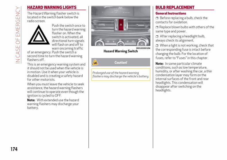
HAZARD WARNING LIGHTSThe Hazard Warning flasher switch islocated in the switch bank below theradio screen.
Push the switch once toturn the hazard warningflasher on. When theswitch is activated, alldirectional turn signalswill flash on and off towarn oncoming traffic
of an emergency. Push the switch asecond time to turn the hazard warningflashers off.This is an emergency warning system andit should not be used when the vehicle isin motion. Use it when your vehicle isdisabled and is creating a safety hazardfor other motorists.When you must leave the vehicle to seekassistance, the hazard warning flasherswill continue to operate even though theignition is cycled to OFF.Note: With extended use the hazardwarning flashers may discharge yourbattery.
Caution!
Prolonged use of the hazard warningflashers may discharge the vehicle’s battery.
BULB REPLACEMENTGeneral Instructions
Before replacing a bulb, check thecontacts for oxidation.
Replace blown bulbs with others of thesame type and power.
After replacing a headlight bulb,always check its alignment.
When a light is not working, check thatthe corresponding fuse is intact beforechanging the bulb. For the location offuses, refer to “Fuses” in this chapter.
Note: In some particular climateconditions, such as low temperature,humidity, or after washing the car, a thincondensation layer may form on theinternal surfaces of the front and rearheadlights. This condensation willdisappear after switching on theheadlights.
08016S0001EM
Hazard Warning Switch
174
INC
AS
EO
FE
ME
RG
EN
CY

Types Of Bulbs
The vehicle may be equipped with the following bulbs
Glass Bulbs (Type A): They are press-fitted. Pull to extract.
Bayonet-Type Bulbs (Type B): To remove them from their holder, press thebulb and turn it counterclockwise, then extract it.
Tubular Bulbs (Type C): Release them from their contacts to remove.
Halogen Bulbs (Type D): To remove the bulb, turn the connector to the sideand pull it out.
Halogen Bulbs (Type E): To remove the bulb, turn it counterclockwise.
Xenon Gas Discharge Bulb (Type F): to remove the bulb, contact anauthorized dealer.
175

Replacement Bulbs
Light bulbs Type Power
Front direction indicators PY24W 24 W
Rear Fog lights H11 55 W
Main beam headlights (Xenon gas discharge) D5S 25 W
Main beam headlights (Xenon gas discharge) D3S 35 W
Sun visor light 1.5CP 2.1 W
Glove compartment light W5W 4 W
Deck lid light W5W 5 W
Puddle lights (under door panel) W5W 5 W
176
INC
AS
EO
FE
ME
RG
EN
CY
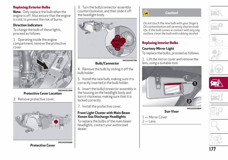
Replacing Exterior BulbsNote: Only replace the bulb when theengine is off. Also ensure that the engineis cold, to prevent the risk of burns.
Direction Indicators
To change the bulb of these lights,proceed as follows:
1. Operating inside the enginecompartment, remove the protectivecover.
2. Remove protective cover.
3. Turn the bulb/connector assemblycounterclockwise, and then slide it offthe headlight body.
4. Remove the bulb by sliding it off thebulb holder.
5. Install the new bulb, making sure it iscorrectly inserted in the bulb holder.
6. Insert the bulb/connector assembly inthe housing on the headlight body andturn it clockwise, making sure that it islocked correctly.
7. Install the protective cover.
Front Light Cluster with Main BeamXenon Gas Discharge Headlights
To replace the bulbs of the main beamheadlights, contact your authorizeddealer.
Caution!
Do not touch the new bulb with your fingers.Oil contamination will severely shorten bulblife. If the bulb comes in contact with any oilysurface, clean the bulb with rubbing alcohol.
Replacing Interior BulbsCourtesy Mirror Light
To replace the bulbs, proceed as follows:
1. Lift the mirror cover and remove thelens, using a suitable tool.
08026S0023EM
Protective Cover Location
08026S0006EM
Protective Cover
08026S0007EM
Bulb/Connector
08026S0008EM
Sun Visor
1 — Mirror Cover2 — Lens
177

2. Change the bulb, releasing it from theside contacts, then insert the new bulb,making sure that it is correctly fastenedbetween the contacts.
3. Install the lens, inserting it firstly onone side and then pressing on the otherside until it clicks into place.
Glove Compartment Light
To replace the bulb, proceed as follows:
1. Open the glove compartment.
2. Remove the courtesy light assembly,using a suitable tool.
3. Open protective cover up and removethe bulb pulling out of the connector.
4. Install bulb, making sure that it iscorrectly inserted fully.
5. Close the protective cover on the lens.
6. Install courtesy light, inserting it firston one side and then pressing on theother side until it clicks into place.
Luggage Compartment Courtesy Lights
To replace the bulbs, proceed as follows:
1. Open the trunk, and remove the trunklamp assembly using a suitable tool.
2. Open protective cover up and removethe bulb pulling out of the connector.
3. Install bulb, making sure that it iscorrectly inserted fully.
4. Close the protective cover on the lens.
5. Install trunk lamp in the correctposition, inserting it firstly on one side,and then pressing on the other side untilit clicks into place.
08026S0009EM
Courtesy Lamp Indent
08026S0011EM
Cover And Bulb Removal Direction08026S0010EM
Ceiling Light Indent
08026S0011EM
Cover And Bulb Removal Direction
178
INC
AS
EO
FE
ME
RG
EN
CY

Puddle Lights On Door Panel
To replace the bulb, proceed as follows:
1. Open the door and remove the puddlelight assembly, using a suitable tool.
2. Open protective cover up and removethe bulb pulling out of the connector.
3. Install bulb, making sure that it iscorrectly inserted fully.
4. Close the protective cover on the lens.
5. Install puddle light in the correctposition, inserting it firstly on one sideand then pressing on the other side untilit clicks into place.
FUSESGeneral InformationThe fuses protect electrical systemsagainst excessive current.When a device does not work, you mustcheck the electrical circuit inside of thefuse for a break/melt.Also, please be aware that using poweroutlets for extended periods of time withthe engine off may result in vehiclebattery discharge.
08026S0012EM
Puddle Light Indent
08026S0011EM
Cover And Bulb Removal Direction
2
3
1
0726067916
Blade Fuses
1 — Electrical Circuit2 — Blade Fuse With Good ElectricalCircuit3 — Blade Fuse With Bad ElectricalCircuit
179

Fuse Extracting Pliers
To replace a fuse, use the pliers hookedto the fuse box.
Grab the pliers from the upper tabs,press them, and extract the pliers pullingupwards.The pliers have two different ends, bothof which are specifically designed toremove the different types of fusespresent in the vehicle:
After use, return the pliers to their properposition by following the belowprocedures:
Grasp the pliers from the upper tabsand insert them into their housing.
Push downward on the pliers into theirhousing until they click into place.
Warning!
When replacing a blown fuse, always usean appropriate replacement fuse with thesame amp rating as the original fuse. Neverreplace a fuse with another fuse of higheramp rating. Never replace a blown fuse withmetal wires or any other material. Failure touse proper fuses may result in seriouspersonal injury, fire and/or propertydamage.
Before replacing a fuse, make sure thatthe ignition is off and that all the otherservices are switched off and/ordisengaged.
If the replaced fuse blows again, contactan authorized dealer.
If a general protection fuse for safetysystems (air bag system, braking system),power unit systems (engine system,transmission system) or steering systemblows, contact an authorized dealer.
Fuse LocationThe fuses, which can be replaced by theuser, are grouped in two boxes below thepassenger side foot board and inside thetrunk.
08036S0002EM
J-CASE Fuse
1 — Electrical Circuit2 — Case Fuse With Good Electrical Cir-cuit3 — Case Fuse With Bad Electrical Cir-cuit
08036S0053EM
Fuse Box
08036S0005EM
Fuse Extracting Pliers
1 — MINI fuse2 — J-CASE fuse
180
INC
AS
EO
FE
ME
RG
EN
CY

Control Unit Under Passenger SideFootboardTo access the fuses, proceed as follows:
1. Lift the upper end of the footboard onthe passenger side, pulling to release thetwo buttons.
Release Buttons On Footboard
1 — Footboard
2. Unscrewing the two hooks, removethe panel pulling downward.
Release Hooks On Footboard
2 — Panel
The fuses are freely accessible on thecontrol unit.After replacing the fuse, make sure thatpanel and footboard are correctly locked.
Luggage Compartment Fuse BoxTo access the fuses, proceed as follows:
1. Lift the luggage compartment cover.
2. Remove the control unit cover.
The fuses are freely accessible on thecontrol unit.The number identifying the electricalcomponent corresponding to each fuse isshown on the cover.After replacing a fuse, make sure thatyou have closed cover correctly.
08036S0010EM
08036S0011EM
08036S0014EM
Control Unit
181

Control Unit Under Passenger Side Footboard
08036S0013EM
Passenger Side Control Unit
182
INC
AS
EO
FE
ME
RG
EN
CY
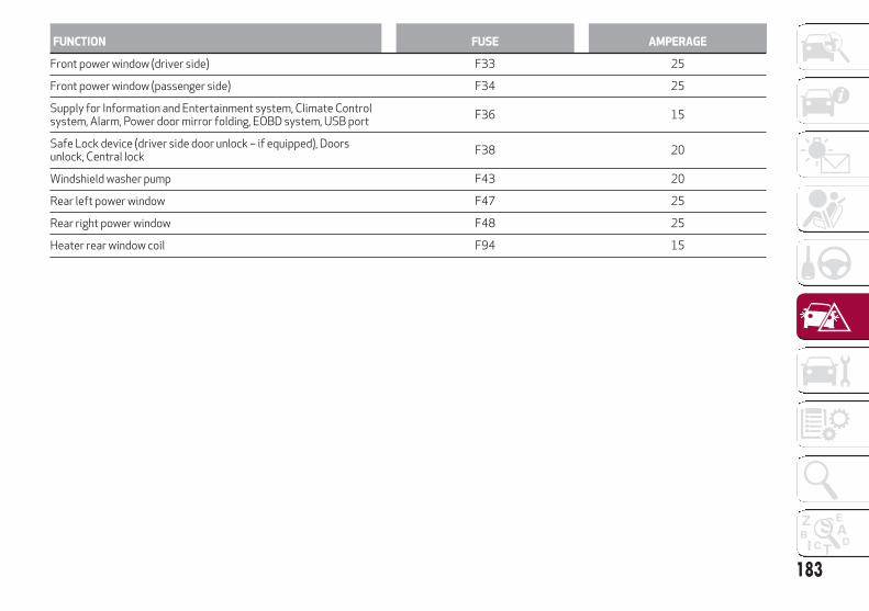
FUNCTION FUSE AMPERAGE
Front power window (driver side) F33 25
Front power window (passenger side) F34 25
Supply for Information and Entertainment system, Climate Controlsystem, Alarm, Power door mirror folding, EOBD system, USB port
F36 15
Safe Lock device (driver side door unlock – if equipped), Doorsunlock, Central lock
F38 20
Windshield washer pump F43 20
Rear left power window F47 25
Rear right power window F48 25
Heater rear window coil F94 15
183

Luggage Compartment Fuse Box
FUNCTION FUSE AMPERAGE
Tow hook module (TTM) F1 40
Hi-Fi system F8 30
KL15/a USB Recharge (C070) F17 7.5
I-Drive / USB / AUX port F21 10
KL15/a 12V Power outlet (R053) F22 20
08036S0015EM
Luggage Compartment Control Unit
184
INC
AS
EO
FE
ME
RG
EN
CY

TIRE REPAIR KIT —IF EQUIPPEDDescriptionIf a tire is punctured, you can make a firstemergency repair using the Tire RepairKit located in the rear storage area underthe load floor.Note: Vehicles equipped with Run FlatTires will not be equipped with a TireRepair Kit.
The Tire Repair Kit includes:
Sealant cartridge containing thesealing fluid.
Filler tube.
Adhesive label with the writing "Max.50 mph (80 km/h)”, to be attached in aposition easily visible to the driver (eg. onthe dashboard) after repairing the tire.
Air compressor, complete withpressure gauge and connectors.
An instruction pamphlet for referencein prompt and correct use of the TireRepair Kit, which must be then given tothe personnel dealing with thesealant-treated tire.
A pair of protective gloves.
Some adaptors, for inflating differentelements.
Note: The sealing fluid is effective withexternal temperatures of between -40°F(-40°C) and 122°F (50°C). The sealingfluid has an expiration date.To use the Tire Repair Kit, proceed asfollows:
1. Stop the vehicle in a position whereyou can repair the tire safely. You shouldbe as far as possible from the side of theroad, and in a position that is notdangerous for oncoming traffic. Engagethe hazard warning flashers, remove thesafety triangle from the luggagecompartment, and place it at a suitabledistance from the vehicle to make otherdrivers aware of your presence.
2. Verify that the valve stem (on thewheel with the deflated tire) is in aposition that is near to the ground. Thiswill allow the tire repair kit hoses to reachthe valve stem and keep the tire repair kitflat on the ground.
3. Shift the gear selector to PARK (P).
4. Apply the electric park brake and turnthe engine OFF.
08066S0001EM
Tire Repair Kit Location08066S0002EM
Tire Repair Kit Components
1— Sealant Cartridge2— Filler Tube3— Adhesive Label4— Air Compressor
185
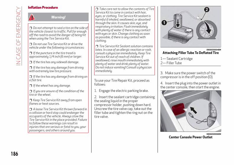
Inflation Procedure
Warning!
Do not attempt to seal a tire on the side ofthe vehicle closest to traffic. Pull far enoughoff the road to avoid the danger of being hitwhen using the Tire Service Kit.
Do not use Tire Service Kit or drive thevehicle under the following circumstances:
If the puncture in the tire tread isapproximately 1/4 inch (6 mm) or larger.
If the tire has any sidewall damage.
If the tire has any damage from drivingwith extremely low tire pressure.
If the tire has any damage from driving ona flat tire.
If the wheel has any damage.
If you are unsure of the condition of thetire or the wheel.
Keep Tire Service Kit away from openflames or heat sources.
A loose Tire Service Kit thrown forward ina collision or hard stop could endanger theoccupants of the vehicle. Always stow theTire Service Kit in the place provided. Failureto follow these warnings can result ininjuries that are serious or fatal to you, yourpassengers, and others around you.
Take care not to allow the contents of TireService Kit to come in contact with hair,eyes, or clothing. Tire Service Kit sealant isharmful if inhaled, swallowed, or absorbedthrough the skin. It causes skin, eye, andrespiratory irritation. Flush immediatelywith plenty of water if there is any contactwith eyes or skin. Change clothing as soonas possible, if there is any contact withclothing.
Tire Service Kit Sealant solution containslatex. In case of an allergic reaction or rash,consult a physician immediately. Keep TireService Kit out of reach of children. Ifswallowed, rinse mouth immediately withplenty of water and drink plenty of water.Do not induce vomiting! Consult a physicianimmediately.
To use your Tire Repair Kit, proceed asfollows:
1. Engage the electric parking brake.
2. Insert the sealant cartridge containingthe sealing liquid in the propercompressor holder, pushing down hard.Unscrew the tire valve cap, take out thefiller tube and tighten the ring nut on thetire valve.
3. Make sure the power switch of thecompressor is in the off position (O).
4. Insert the plug into the power outlet inthe center console, then start the engine.
08066S0004EM
Attaching Filler Tube To Deflated Tire
1— Sealant Cartridge2— Filler Tube
08066S0006EM
Center Console Power Outlet
186
INC
AS
EO
FE
ME
RG
EN
CY
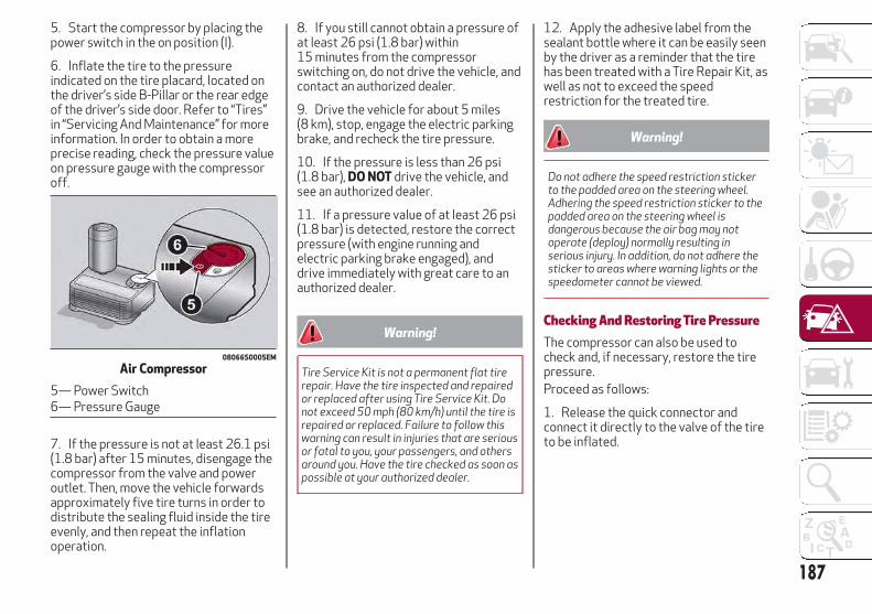
5. Start the compressor by placing thepower switch in the on position (I).
6. Inflate the tire to the pressureindicated on the tire placard, located onthe driver’s side B-Pillar or the rear edgeof the driver’s side door. Refer to “Tires”in “Servicing And Maintenance” for moreinformation. In order to obtain a moreprecise reading, check the pressure valueon pressure gauge with the compressoroff.
7. If the pressure is not at least 26.1 psi(1.8 bar) after 15 minutes, disengage thecompressor from the valve and poweroutlet. Then, move the vehicle forwardsapproximately five tire turns in order todistribute the sealing fluid inside the tireevenly, and then repeat the inflationoperation.
8. If you still cannot obtain a pressure ofat least 26 psi (1.8 bar) within15 minutes from the compressorswitching on, do not drive the vehicle, andcontact an authorized dealer.
9. Drive the vehicle for about 5 miles(8 km), stop, engage the electric parkingbrake, and recheck the tire pressure.
10. If the pressure is less than 26 psi(1.8 bar), DO NOT drive the vehicle, andsee an authorized dealer.
11. If a pressure value of at least 26 psi(1.8 bar) is detected, restore the correctpressure (with engine running andelectric parking brake engaged), anddrive immediately with great care to anauthorized dealer.
Warning!
Tire Service Kit is not a permanent flat tirerepair. Have the tire inspected and repairedor replaced after using Tire Service Kit. Donot exceed 50 mph (80 km/h) until the tire isrepaired or replaced. Failure to follow thiswarning can result in injuries that are seriousor fatal to you, your passengers, and othersaround you. Have the tire checked as soon aspossible at your authorized dealer.
12. Apply the adhesive label from thesealant bottle where it can be easily seenby the driver as a reminder that the tirehas been treated with a Tire Repair Kit, aswell as not to exceed the speedrestriction for the treated tire.
Warning!
Do not adhere the speed restriction stickerto the padded area on the steering wheel.Adhering the speed restriction sticker to thepadded area on the steering wheel isdangerous because the air bag may notoperate (deploy) normally resulting inserious injury. In addition, do not adhere thesticker to areas where warning lights or thespeedometer cannot be viewed.
Checking And Restoring Tire PressureThe compressor can also be used tocheck and, if necessary, restore the tirepressure.Proceed as follows:
1. Release the quick connector andconnect it directly to the valve of the tireto be inflated.
08066S0005EM
Air Compressor
5— Power Switch6— Pressure Gauge
187

2. Push the air release button.
Sealant Cartridge ReplacementNote: Only use original cartridges, whichcan be purchased at an authorized dealer.
Proceed as follows:
1. Remove the sealant cartridge bypushing the release button located on theside of the compressor.
2. Insert the new sealant cartridge bypushing downward firmly.
JUMP STARTINGIf your vehicle has a discharged battery, itcan be jump started using a set of jumpercables and a battery in another vehicle, orby using a portable battery booster pack.Jump starting can be dangerous if doneimproperly, so please follow theprocedures in this section carefully.Note: When using a portable batterybooster pack, follow the manufacturer'soperating instructions and precautions.
Warning!
Do not attempt jump-starting if the batteryis frozen. It could rupture or explode andcause personal injury.
Caution!
Do not use a portable battery booster packor any other booster source with a systemvoltage greater than 12 Volts or damage tothe battery, starter motor, alternator orelectrical system may occur.
Remote Battery Connection PostsThe remote posts of the battery for jumpstarting can be found inside the enginecompartment. The battery itself islocated in the luggage compartment.The negative terminal (-) is positionednext to the passenger side hood lock.
08066S0008EM
Air Compressor Components
7— Air Release Button8— Quick Connector9— Release Button
08066S0009EM
Sealant Cartridge Replacement
1— Sealant Cartridge9— Release Button
08076S0006EM
Remote Negative Post Location
188
INC
AS
EO
FE
ME
RG
EN
CY

Warning!
Do not connect the jumper cable to thenegative (-) post of the discharged battery.The resulting electrical spark could causethe battery to explode and could result inserious injury. Only use the specific groundpoint, do not use any other exposed metalparts.
The positive post (+) can be accessed byremoving the cover, and opening theprotective flap.
To carry out the operation, you need tohave the correct cables to connect to thebattery of another vehicle or a portablebattery booster pack to the remote postsof the discharged battery. Usually, thesecables have terminals at the ends and areidentified by different sheath colors (red= positive, black = negative).
Jump Starting
Warning!
Failure to follow this jump-startingprocedure could result in personal injury orproperty damage due to battery explosion.
Caution!
Failure to follow these procedures couldresult in damage to the charging system ofthe booster vehicle or the dischargedvehicle.
Preparation For Jump Starting:
1. Firmly apply the parking brake, andcycle the ignition to OFF.
2. Switch off all electrical features in thevehicle.
3. If using another vehicle to jump startthe battery, park the vehicle within thejumper cables reach, apply the park brakeand make sure the ignition cycled OFF.
Warning!
Do not allow vehicles to touch each other asthis could establish a ground connection andpersonal injury could result.08076S0007EM
Protective Flap
08076S0001EM
Remote Positive Post Location
189

Cable Connection
Proceed as follows to perform a jumpstarting procedure:
1. Connect the positive (+) end of thejumper cable to the positive (+) post ofthe vehicle with the discharged battery
2. Connect the opposite end of thepositive (+) jumper cable to the positive(+) post of the booster battery.
3. Connect the negative end (-) of thejumper cable to the negative (-) post ofthe booster battery.
4. Connect the opposite end of thenegative (-) jumper cable to a good engineground of the vehicle with the dischargedbattery (exposed metal part of theengine) away from the battery and thefuel injection system.
Warning!
Do not connect the jumper cable to thenegative (-) post of the discharged battery.The resulting electrical spark could causethe battery to explode and could result inserious injury. Only use the specific groundpoint, do not use any other exposed metalparts.
5. Start the engine in the vehicle that hasthe booster battery, let the engine idle afew minutes, and then start the engine inthe vehicle with the discharged battery. Ifusing a portable battery booster pack,before starting the vehicle, wait a fewseconds after completing the connection.
Cable Disconnection
Once the engine is started, remove theconnection cables in reverse sequence,as described below:
1. Disconnect the negative (-) jumpercable from the engine (-) ground of thevehicle with the discharged battery.
2. Disconnect the negative end (-) of thejumper cable from the negative (-) post ofthe booster battery.
3. Disconnect the opposite end of thepositive (+) jumper cable from thepositive (+) post of the booster battery.
4. Disconnect the positive (+) end of thejumper cable from the positive (+) post ofthe vehicle with the discharged battery.
If frequent jump starting is required tostart your vehicle, you should have thebattery and charging system inspected atyour authorized dealer.
Caution!
Accessories plugged into the vehicle poweroutlets draw power from the vehicle’sbattery, even when not in use (i.e., cellularphones, etc.). Eventually, if plugged in longenough without engine operation, thevehicle’s battery will discharge sufficientlyto degrade battery life and/or prevent theengine from starting.
Bump StartingNever jump start the engine by pushing,towing or coasting downhill.Note: You cannot start a vehicle with anautomatic transmission by pushing it.
Caution!
Accessories plugged into the vehicle poweroutlets draw power from the vehicle’sbattery, even when not in use (i.e., cellularphones, etc.). Eventually, if plugged in longenough without engine operation, thevehicle’s battery will discharge sufficientlyto degrade battery life and/or prevent theengine from starting.
190
INC
AS
EO
FE
ME
RG
EN
CY

REFUELING IN EMERGENCYRefueling in an emergency is described in"Refueling The Vehicle" in "Starting AndOperating".
ENGINE OVERHEATINGEngine overheating may occur insituations of extreme environmentaltemperatures, frequent enginestops/starts, or driving in heavy traffic. Ifthe engine becomes overheated, theEngine Temperature Warning Light in theinstrument cluster will illuminate alongwith a dedicated message. Refer to"Warning Lights And Messages" in the"Getting To Know Your Instrument Panel"for more information.In any of the following situations, you canreduce the potential for overheating bytaking the appropriate action.
On the highways — slow down.
In city traffic — while stopped, placethe transmission in NEUTRAL, but do notincrease engine idle speed.
Note: There are steps that you can taketo slow down an impending overheatcondition:
If your air conditioner (A/C) is on, turnit off. The A/C system adds heat to theengine cooling system and turning theA/C off can help remove this heat.
You can also turn the temperaturecontrol to maximum heat, the modecontrol to floor and the blower control tohigh. This allows the heater core to actas a supplement to the radiator and aidsin removing heat from the engine coolingsystem.
Warning!
You or others can be badly burned by hotengine coolant (antifreeze) or steam fromyour radiator. If you see or hear steamcoming from under the hood, do not open thehood until the radiator has had time to cool.Never try to open a cooling system pressurecap when the radiator or coolant bottle ishot.
Caution!
Driving with a hot cooling system coulddamage your vehicle. If temperature gaugereads “H”, pull over and stop the vehicle. Idlethe vehicle with the air conditioner turnedoff until the pointer drops back into thenormal range. If the pointer remains on the“H”, turn the engine off immediately, and callfor service.
191
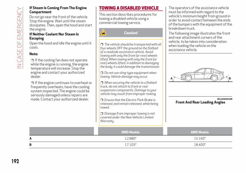
If Steam Is Coming From The EngineCompartment
Do not go near the front of the vehicle.Stop the engine. Wait until the steamdissipates. Then, open the hood and startthe engine.If Neither Coolant Nor Steam IsEscaping
Open the hood and idle the engine until itcools.
Note:
If the cooling fan does not operatewhile the engine is running, the enginetemperature will increase. Stop theengine and contact your authorizeddealer.
If the engine continues to overheat orfrequently overheats, have the coolingsystem inspected. The engine could beseriously damaged unless repairs aremade. Contact your authorized dealer.
TOWING A DISABLED VEHICLEThis section describes procedures fortowing a disabled vehicle using acommercial towing service.
Caution!
The vehicle should be transported with allfour wheels OFF the ground on the flatbedof a roadside assistance vehicle. Avoidtowing with only the front (or rear) wheelslifted. When towing with only the front (orrear) wheels lifted, in addition to damagingthe body, it could damage the transmission.
Do not use sling-type equipment whentowing. Vehicle damage may occur.
When securing the vehicle to a flatbedtruck, do not attach to front or rearsuspension components. Damage to yourvehicle may result from improper towing.
Ensure that the Electric Park Brake isreleased, and remain released, while beingtowed.
Damage from improper towing is notcovered under the New Vehicle LimitedWarranty.
The operators of the assistance vehiclemust be informed with regard to thevehicle's minimum height from ground inorder to avoid contact between the endsof the bumpers with the equipment of thebreakdown truck.The following image illustrates the frontand rear attachment corners of thevehicle, to be taken into considerationwhen loading the vehicle on theassistance vehicle.
RWD Models AWD Models
A 12.880° 15.160°
B 17.105° 18.400°
08126S0001EM
Front And Rear Loading Angles
192
INC
AS
EO
FE
ME
RG
EN
CY

Rear Wheel Drive (RWD) ModelsIt is recommended to tow the vehiclewith all four wheels OFF the ground onthe flatbed of a roadside assistancevehicle.
Caution!
Do not use sling type equipment whentowing. Vehicle damage may occur.
When securing the vehicle to a flat bedtruck, do not attach to front or rearsuspension components. Damage to yourvehicle may result from improper towing.
Ensure that the Electric Park Brake isreleased, and remains released, while beingtowed.
If an assistance vehicle with a flatbed isnot available, the vehicle must be towedwith the rear wheels lifted from theground using a trailer or specialequipment allowing lifting of the rearwheels.
Four-Wheel Drive (AWD) ModelsIt is recommended to tow the vehiclewith all four wheels OFF the ground onthe flatbed of a roadside assistancevehicle.
Caution!
DO NOT flat tow this vehicle. Damage tothe drivetrain will result.
DO NOT dolly tow this vehicle. Use of atowing dolly can cause significant damageto your vehicle.Towing this vehicle in violation of the aboverequirements can cause severe transmissiondamage. Damage from improper towing isnot covered under the New Vehicle LimitedWarranty.
TOW EYESIf the vehicle has been in an accident orhas broken down, a tow eye is provided inthe tools container located inside theluggage compartment for vehicle towing.Towing is meant only for short distanceson a paved road surface.Proceed as follows to use the tow eye:
1. Unhook the cap on the front or rearbumper (if equipped), pushing on theupper part.
08136S0001EM
Front Tow Eye Cap
08136S0003EM
Rear Tow Eye Cap 193
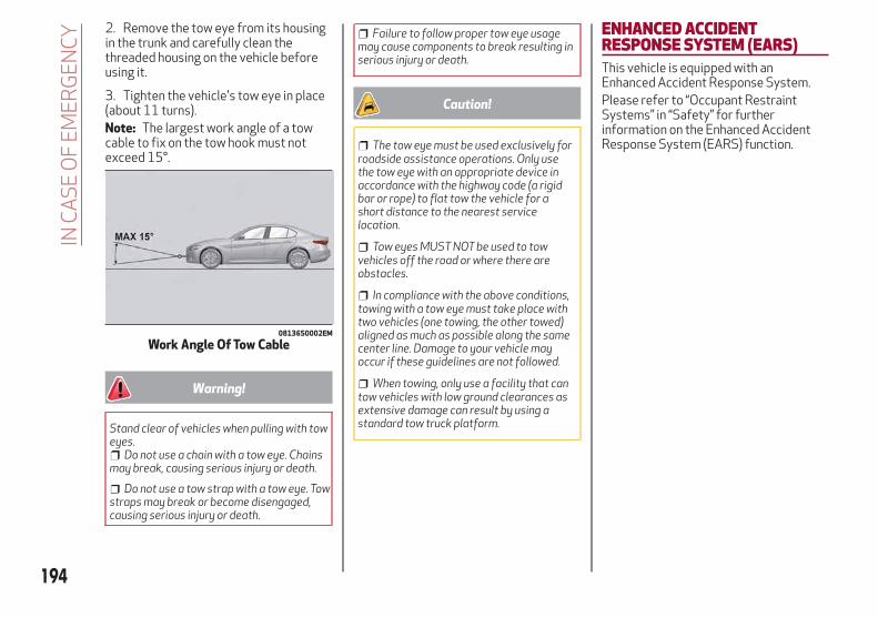
2. Remove the tow eye from its housingin the trunk and carefully clean thethreaded housing on the vehicle beforeusing it.
3. Tighten the vehicle's tow eye in place(about 11 turns).Note: The largest work angle of a towcable to fix on the tow hook must notexceed 15°.
Warning!
Stand clear of vehicles when pulling with toweyes.
Do not use a chain with a tow eye. Chainsmay break, causing serious injury or death.
Do not use a tow strap with a tow eye. Towstraps may break or become disengaged,causing serious injury or death.
Failure to follow proper tow eye usagemay cause components to break resulting inserious injury or death.
Caution!
The tow eye must be used exclusively forroadside assistance operations. Only usethe tow eye with an appropriate device inaccordance with the highway code (a rigidbar or rope) to flat tow the vehicle for ashort distance to the nearest servicelocation.
Tow eyes MUST NOT be used to towvehicles off the road or where there areobstacles.
In compliance with the above conditions,towing with a tow eye must take place withtwo vehicles (one towing, the other towed)aligned as much as possible along the samecenter line. Damage to your vehicle mayoccur if these guidelines are not followed.
When towing, only use a facility that cantow vehicles with low ground clearances asextensive damage can result by using astandard tow truck platform.
ENHANCED ACCIDENTRESPONSE SYSTEM (EARS)This vehicle is equipped with anEnhanced Accident Response System.Please refer to “Occupant RestraintSystems” in “Safety” for furtherinformation on the Enhanced AccidentResponse System (EARS) function.
08136S0002EM
Work Angle Of Tow Cable
194
INC
AS
EO
FE
ME
RG
EN
CY

EVENT DATA RECORDER (EDR)This vehicle is equipped with an EventData Recorder (EDR). The main purposeof an EDR is to record data that willassist in understanding how a vehicle’ssystems performed under certain crashor near crash-like situations, such as anair bag deployment or hitting a roadobstacle.Please refer to “Occupant RestraintSystems” in “Safety” for furtherinformation on the Event Data Recorder(EDR).
195

196
This page is intentionally left blank
SERVICING AND MAINTENANCE
Correct servicing permits theperformance of the vehicle to bemaintained over time, as well as limitedrunning costs and safeguarding theefficiency of the safety systems.
This chapter explains how.
SCHEDULED SERVICING . . . . . . .198ENGINE COMPARTMENT . . . . . . .203BATTERY RECHARGING . . . . . . . .206DEALER SERVICE . . . . . . . . . . . .207RAISING THE VEHICLE . . . . . . . . .213TIRES . . . . . . . . . . . . . . . . . . .213DEPARTMENT OF TRANSPORTATIONUNIFORM TIRE QUALITY GRADES . .230STORING THE VEHICLE . . . . . . . .231BODYWORK . . . . . . . . . . . . . . .232INTERIORS . . . . . . . . . . . . . . . .233
197

SCHEDULED SERVICINGCorrect servicing is crucial for guaranteeing a long life for the vehicle under the best conditions.For this reason, Alfa Romeo has planned a series of checks and services for your vehicle at fixed intervals based on distance andtime, as described in the Scheduled Servicing Plan.Before each service, it is always necessary to carefully follow the instructions in the Scheduled Servicing Plan (e.g. periodically checklevel of fluids, tire pressure, etc.).Scheduled Servicing is offered by an authorized dealer according to a set time schedule. If, during each operation, in addition to theones scheduled, the need arises for further replacements or repairs, these may be carried out with the owner’s explicit consent only.Note: Scheduled Servicing intervals are required by the Manufacturer. Failure to have them carried out may invalidate the NewVehicle Limited Warranty.You are advised to inform your authorized dealer of any small operating irregularities without waiting for the next service.
Periodic ChecksEvery month or every 600 miles ( 1,000 km) or before long trips check and, if necessary, top off:
Engine coolant level.
Brake fluid level (if insufficient, see your authorized dealer as soon as possible).
Windshield washer fluid level.
Tire inflation pressure and condition.
Operation of lighting system (headlights, direction indicators, hazard warning lights, etc.).
Operation of windshield washing/wiping system and positioning/wear of wiper blades.
Every 2,000 miles ( 3,000 km), check and top off if required:Engine oil level.
198
SE
RV
ICIN
GA
ND
MA
INT
EN
AN
CE
Heavy Usage Of The VehicleIf the vehicle is used under one of the following conditions:
Dusty roads.
Short, repeated journeys less than 4 miles (7-8 km) at sub-zero outside temperatures.
Engine often idling or driving long distances at low speeds or long periods of inactivity.
In the event of a long period of inactivity.
The following checks must be carried out more often than indicated in the Scheduled Servicing Plan:Check cleanliness of hood and trunk locks, cleanliness and lubrication of linkage.
Visually inspect conditions of: engine, transmission, pipes and hoses (exhaust/fuel system/brakes) and rubber elements(sleeves/bushes, etc.).
Check battery charge and battery fluid level (electrolyte).
Visually inspect conditions of the accessory drive belts.
Check and, if necessary, change engine oil and replace oil filter.
Check and, if necessary, replace cabin air filter.
Check and, if necessary, replace air cleaner.
Severe Duty All Models
Change Engine Oil at 4,000 miles (6,500 km) if the vehicle is operated in a dusty and off-road environment or is operatedpredominately at idle or only very low engine RPM’s. This type of vehicle use is considered Severe Duty.
199

Maintenance Plan (2.0 T4 MAir Engine)
Thousands of miles 10
20 30
40 50
60
70
80
90
10
0
11
0
12
0
13
0
14
0
15
0
Years 1 2 3 4 5 6 7 8 9 10 11 12 13 14 15
Thousands of kilometers 16
32 48
64 80
96
11
2
12
8
14
4
16
0
17
6
19
2
20
8
22
4
24
0
Check battery charge status with the proper instrument ● ● ● ● ● ● ● ● ● ● ● ● ● ● ●
Check tire condition/wear and adjust pressure, if necessary.Check the tire repair kit recharge condition and expire date
● ● ● ● ● ● ● ● ● ● ● ● ● ● ●
Check operation of lighting system (headlights, directionindicators, hazard warning lights, deck lid, passengercompartment, glove compartment, instrument panel warninglights, etc.)
● ● ● ● ● ● ● ● ● ● ● ● ● ● ●
Check and, if necessary, top up fluid levels (1) ● ● ● ● ● ● ● ● ● ● ● ● ● ● ●
Check engine control system operation (via diagnostic tool)and, if equipped, engine oil degradation (2)
● ● ● ● ● ● ● ● ● ● ● ● ● ● ●
Visually inspect conditions of: exterior bodywork, underbodyprotection, pipes and hoses (exhaust, fuel system, brakes),rubber elements (sleeves, bushes, etc.)
● ● ● ● ● ● ●
Check position/wear of front windshield wiper blade ● ● ● ● ● ● ● ●
Check operation of the windshield wiper/washer system andadjust nozzles, if necessary
● ● ● ● ● ● ● ●
(1) Top up using the fluids indicated in the “Fluids And Lubricants” section of the “Technical Specifications” chapter only after checking that the system is intact.(2) If oil degradation ratio (data collectable from diagnostic device) is more than 80% (oil quality less than 20%) engine oil and filter replacement is recommended.
200
SE
RV
ICIN
GA
ND
MA
INT
EN
AN
CE

Thousands of miles 10
20 30
40 50
60
70
80
90
10
0
11
0
12
0
13
0
14
0
15
0
Years 1 2 3 4 5 6 7 8 9 10 11 12 13 14 15
Thousands of kilometers 16
32 48
64 80
96
11
2
12
8
14
4
16
0
17
6
19
2
20
8
22
4
24
0
Check cleanliness of hood and luggage compartment locks,cleanliness and lubrication of linkage
● ● ● ● ● ● ●
Visually inspect conditions and wear of front/rear disc brakepads and operation of pad wear indicators
● ● ● ● ● ● ● ● ● ● ● ● ● ● ●
Visually inspect the condition and tensioning of theaccessory drive belt(s)
● ● ● ● ● ● ● ● ● ● ● ●
Change engine coolant ●
Change engine oil and replace oil filter (3)
Replace transfer case oil (AWD models only) ●
Replace accessory drive belt/s (4)
Replace air cleaner cartridge (5) ● ● ● ● ●
Replace the additional fuel filter (if equipped) ● ● ● ● ● ● ● ● ● ● ● ● ● ● ●
Change the brake fluid (6)
(3) The actual interval for changing engine oil and replacing the engine oil filter depends on the vehicle usage conditions and is signaled by the warning light or message inthe instrument panel. In all cases, never exceed 1 year/10,000 miles.
(4) Areas that are not dusty: recommended maximum mileage 36,000 miles (60,000 km). Regardless of the mileage, the belt must be replaced every 4 years. Dusty areasand/or demanding use of the vehicle (cold climates, town use, long periods of idling): advised maximum mileage 18,000 miles (30,000 km). Regardless of the mileage,the belt must be replaced every 2 years.
(5) If the vehicle is used in dusty areas, this cleaner must be replaced every 10,000 miles (16,000 km).(6) The brake fluid replacement has to be done every two years, irrespective of the mileage.
201

Thousands of miles 10
20 30
40 50
60
70
80
90
10
0
11
0
12
0
13
0
14
0
15
0
Years 1 2 3 4 5 6 7 8 9 10 11 12 13 14 15
Thousands of kilometers 16
32 48
64 80
96
11
2
12
8
14
4
16
0
17
6
19
2
20
8
22
4
24
0
Replace the passenger compartment cleaner (5) o ● o ● o ● o ● o ● o ● o ● o
Spark plug replacement * ● ● ● ● ●
(5) If the vehicle is used in dusty areas, this cleaner must be replaced every 10,000 miles (16,000 km).*The spark plug change interval is mileage-based only. Yearly intervals do not apply.
(o) Recommended operations(●) Mandatory operations
Warning!
You can be badly injured working on or around a motor vehicle. Do only service work for which you have the knowledge and the right equipment.If you have any doubt about your ability to perform a service job, take your vehicle to a competent mechanic.
Failure to properly inspect and maintain your vehicle could result in a component malfunction and effect vehicle handling and performance.This could cause an accident.
202
SE
RV
ICIN
GA
ND
MA
INT
EN
AN
CE

ENGINE COMPARTMENTChecking Levels2.0 T4 MAir engine
09026S0002EM
1 – Engine Oil Filler Cap 4 –Windshield/Headlights Washer Fluid Reservoir Cap2 – Brake Fluid Reservoir Access Cover 5 – Intercooler Coolant Reservoir Cap3 – Engine Coolant Reservoir Cap
203

Engine OilThe engine oil level can be seen on theinstrument cluster display every time theengine is started, or on the Informationand Entertainment system display byactivating on the main menu (MENUbutton) the following functions insequence: “Apps”; “My Car” and “OilLevel”.Check on the display using the 6 notchesthat the oil level is between the MIN andMAX level: 1 notch MIN level, 6 notchesMAX level.If the oil level is close to or below the MINmark, add oil gradually through the filler,(refer to “Top-Up And Oil Level IndicationUpdate On Display” in this section)considering that each notch shown on thedisplay corresponds to approximately8.8 fl oz (250 ml).
Caution!
Make sure not to add too much oil whentopping off the engine. Engine oil in excessmay damage the engine. Have the vehiclechecked. Never exceed the MAX level whentopping off engine oil.
Caution!
The oil level is not refreshed immediately onthe display after topping off. Consequently,wait for the oil level to be refreshed on thedisplay and follow the procedure below.
Note: Always reinstall the oil cap andtighten to proper torque whenever it isremoved to add oil to engine. Never runthe engine with cap removed this couldcause oil to leak from engine.
Top-Up And Oil Level Indication UpdateOn Display
If a engine oil top-off is needed, in orderto ensure the correct indication of the oillevel on the display, leave the vehicle onflat ground with the engine running forapproximately 5 minutes (temperaturehigher than 176°F (80°C)) and shut theengine off then proceed with the processbelow:
Start the engine again and idle it forabout five minutes.
Note: If you have added the specifiedamount of oil and the indicator is notreading “Full”, please contact yourauthorized dealer.
Warning!
If the engine oil is being topped up, wait forthe engine to cool down before loosening thefiller cap, particularly for vehicles withaluminium cap (if equipped). WARNING: riskof burns!
Caution!
The oil level must never exceed the MAXmark.
If the MAX mark is exceeded MAX (lastnotch on the right turns red) after the fill-up,go to your authorized dealer as soon aspossible to have the oil in excess removed.
Do not add oil with specificationsdifferent from those of the oil already in theengine.
Used engine oil and oil filters containsubstances which are harmful to theenvironment. To change the oil and filters,we advise you to contact your authorizeddealer.
Engine Coolant FluidIf the level is too low, unscrew the cap ofreservoir and add the fluid described inthe "Technical Specifications" chapter.
204
SE
RV
ICIN
GA
ND
MA
INT
EN
AN
CE
Washer Fluid For Windshield/HeadlightsThe windshield and headlights washerfluid reservoir (if equipped) has atelescopic filler.If the level is too low, remove reservoircap and lift the filler. Then, add the fluiddescribed in the "TechnicalSpecifications" chapter.Note: The headlight washing system willnot work if the liquid level is low (asindicated by the symbol on theinstrument cluster display). Thewindshield washer will keep working. Onvehicles equipped with headlightwashers, if equipped, there is a referencenotch on the dipstick: ONLY thewindshield/rear window washer operateswith the level below this reference.
Brake FluidCheck that the fluid is at the maximumlevel. If the fluid level in the tank is low,contact your authorized dealer to havethe system checked.
Automatic Transmission ActivationSystem OilThe transmission control oil level shouldonly be checked at your authorizeddealer.
Useful Advice For Extending The LifeOf Your BatteryTo avoid draining your battery and makeit last longer, observe the followinginstructions:
When you park the car, ensure that thedoors and trunk are closed properly toprevent any lights from remaining oninside the passenger's compartment.
Do not keep accessories (e.g. radio,hazard warning lights, etc.) switched onfor a long time when the engine is notrunning.
Before performing any operation onthe electrical system, disconnect thenegative battery cable.
If you wish to install electricalaccessories after purchasing the car thatrequire permanent electrical supply (e.g.alarm, etc.), or accessories whichinfluence the electrical supplyrequirements, contact your authorizeddealer, whose qualified staff will evaluatethe overall electrical consumption.
Caution!
If the charge level remains under 50% for along time, the battery may be damaged bysulphation, reducing its capacity andefficiency at start the vehicle. The battery isalso more prone to the risk of freezing (attemperatures as high as 14°F (-10°C).
Note: After the battery is disconnected,the steering must be initialized. The
warning light on the instrument panelswitches on to indicate this. To carry outthis procedure, simply turn the steeringwheel all the way from one end to theother, and then turn it back to the centralposition.
BatteryThe battery does not require theelectrolyte to be topped up with distilledwater. A periodic check carried out at anauthorized dealer, however, is necessaryto check efficiency.Follow the battery manufacturer'sinstructions for maintenance.
Replacing The Battery
If necessary, replace the battery withanother original battery with the samespecifications. Follow the batterymanufacturer’s instructions formaintenance.
Warning!
Battery acid is a corrosive solution andcan burn or even blind you. Do not allowbattery acid to contact your eyes, skin, orclothing. Do not lean over a battery whenattaching clamps. If acid splashes in eyes oron skin, flush the area immediately withlarge amounts of water. Refer to “JumpStarting” in “In Case Of Emergency” forfurther information.
205

Battery gas is flammable and explosive.Keep flame or sparks away from thebattery. Do not use a booster battery or anyother booster source with an output greaterthan 12 Volts. Do not allow cable clamps totouch each other.
Battery posts, terminals, and relatedaccessories contain lead and leadcompounds. Wash hands after handling.
Note: It will not be possible to open thetrunk with a key or by pressing the buttonin the passenger compartment when thebattery is disconnected. So, alwaysposition the manual trunk opening strapon the trunk lock before disconnectingthe battery. The procedure is described inthe "Storing The Vehicle" paragraph inthis chapter.
BATTERY RECHARGINGImportant Notes
Warning!
Never charge or recharge a frozenbattery: it may explode because of thenitrogen trapped inside the ice crystals.
At all times while charging or rechargingthe battery, make sure that any sparks oropen flames are kept sufficiently far awayfrom the battery.
Note:
Before using the charging device,always make sure that it is appropriatefor the installed battery, with constantvoltage (below 14.8 V) and lowamperage (maximum 15 A).
Recharge the battery in a wellventilated environment.
Before using any devices to charge orto maintain the charge of the battery,carefully follow the instructionsprovided with the device in order toproperly and safely connect it to the carbattery.
You can recharge the battery withoutdisconnecting the wires of the vehicle'selectrical system.
To reach the battery, remove theaccess panel inside the trunk.
Remove the protective cover andconnect the positive cable terminal of thecharger (usually red) to the positiveterminal (+) of the battery.
Connect the negative terminal of thecharger (usually black) to nut next to thenegative terminal (-) of the battery.
09036S0001EM
Battery Access Panel
09036S0002EM
Battery
1 — Protective Cover2 — Negative Post (Nut)
206
SE
RV
ICIN
GA
ND
MA
INT
EN
AN
CE
The vehicle is equipped with an IBS(Intelligent Battery Sensor), which is ableto measure the charge and dischargevoltage and calculate the charge leveland the general condition of the battery.The sensor is placed next to the negativeterminal (-) of the battery.For a correct charge/dischargeprocedure, the charge voltage must gothrough the IBS sensor.
1. Turn the charger on and follow theinstructions on the user's manual tocompletely recharge the battery.
2. When the battery is charged, turn thecharger off before disconnecting it fromthe battery.
3. Disconnect the black cable terminal ofthe battery charger and then the redcable terminal.
4. Refit the protective cover of thepositive terminal of the battery and theaccess cover to the batterycompartment.
Note: If a "quick-type" battery charger isused with the battery fitted on thevehicle, before connecting it disconnectboth cables of the battery itself. Do notuse a "quick-type" battery charger toprovide the starting voltage.
DEALER SERVICEThe following pages contain instructionson the required maintenance from thetechnical personnel who designed thevehicle.In addition to these specific maintenanceinstructions specified for routinescheduled servicing, there are othercomponents which may require periodicmaintenance or replacement over thevehicle’s life cycle.
Engine OilEngine Oil Level Check
To ensure correct engine lubrication, theoil must always be kept at the prescribedlevel (see "Engine Compartment" in thischapter).Check the oil level at regular intervals, forexample every 1864 miles (3000 km).It must be checked about five minutesafter stopping the engine, once fulloperating temperature is reached. Thevehicle must also be parked on as level asurface as possible.The engine oil level can be checked usingthe Information and Entertainmentsystem. To access the function, activatethe main menu (MENU button) and selectthe following options in sequence:“Applications”; “My Car”; “Oil level”.
Changing The Engine Oil
See the "Maintenance Plan" for thecorrect servicing intervals.
Choice Of Engine Oil Type
To ensure optimal performance andmaximum protection in all operatingconditions, it is advisable to use solelycertified engine oils (see description in"Fluid And Lubricants" in the "TechnicalSpecifications" chapter).
Additives For Engine Oil
It is strongly recommended not to useadditives (other than leak detection dyes)with the engine oil.The engine oil is a product designedspecially for the vehicle and itsperformance may be deterioratedthrough the use of further additives.
Disposal Of Used Engine Oil And Filters
For the disposal of the engine oil andfilters, contact the appropriate body todetermine local regulations.Note: Used engine oil disposed ofincorrectly may seriously harm theenvironment.
207

Engine Oil FilterReplacing The Engine Oil Filter
The engine oil filter must be replacedeach time the engine oil is changed. It isadvised to replace it with a genuine sparepart, specifically designed for thisvehicle.
Air FilterReplacing The Air Cleaner
See the "Maintenance Plan" for thecorrect servicing intervals. It is advised toreplace it with a genuine spare part,specifically designed for this vehicle.
Air Conditioning System MaintenanceTo ensure the best possible performance,the air conditioning system must bechecked and undergo maintenance at anauthorized dealer at the beginning of thesummer.
Caution!
Do not use chemicals to clean the airconditioning system, since the internalcomponents may be damaged. This kind ofdamage is not covered by warranty.
Replace The Cabin Air Filter
See the "Maintenance Plan" for thecorrect servicing intervals. For cleanerreplacement, contact an authorizeddealer.
Warning!
Use only refrigerants and compressorlubricants approved by the manufacturer foryour air conditioning system. Someunapproved refrigerants are flammable andcan explode, injuring you. Other unapprovedrefrigerants or lubricants can cause thesystem to fail, requiring costly repairs. Referto Warranty Information Book, located inyour owner’s information kit, for furtherwarranty information.
Lubricating Moving Parts Of TheBodyworkEnsure that the locks and bodyworkjunction points, including componentssuch as the seat guides, door hinges (androllers), trunk and hood are periodicallylubricated with lithium-based grease toensure correct, silent operation and toprotect them from rust and wear.Thoroughly clean the components,eliminating every trace of dirt and dust.After lubricating, eliminate excess oil andgrease. Also pay particular attention tothe hood closing devices, to ensurecorrect operation. During operations onthe hood, to be carried out with theengine cold, also remember to check,clean and lubricate the locking, releaseand safety devices.
Lubricate the external lock barrels twicea year. Apply a small amount ofhigh-quality lubricant directly into thelock barrel.If necessary, contact your authorizeddealer as soon as possible.
Windshield WiperPeriodically clean the windshield and rearwindow and rubber profile of thewindshield wiper blades, using a spongeor a soft cloth and a non-abrasivedetergent. This eliminates the salt orimpurities accumulated when driving.Prolonged operation of the windshieldwindow wipers with dry glass may causethe deterioration of the blades, inaddition to abrasion of the surface of theglass. To eliminate the impurities on thedry glass, always operate the windshieldwashers.In the event of very low outdoortemperatures, below zero degrees,ensure that the movement of the rubberpart in contact with the glass is notobstructed. Use a suitable deicingproduct to release it if required.Avoid using the windshield wipers toremove frost or ice.Also avoid contact of the rubber profileof the blades with petroleum derivativessuch as engine oil, gas, etc.
208
SE
RV
ICIN
GA
ND
MA
INT
EN
AN
CE

Warning!
Driving with worn windshield wiper blades isa serious hazard, because visibility isreduced in bad weather conditions.
Note: The life of the windshield wiperblades varies according to the usagefrequency. In any case, it is advised toreplace the blades approximately once ayear. When the blades are worn, noise,marks on the glass or streaks of watermay be noticed. In the presence of theseconditions, clean the windshield wiperblades or, if necessary, replace them.
Raising The Windshield Wiper Blades("Service Position" Function)
The "service position" function allows thedriver to replace the windshield wiperblades more easily. It is alsorecommended to activate this functionwhen it is snowing and to make it easierto remove any dirt deposits in the areawhere the blades are normallypositioned, when washing.
Activation Of The Function
To activate this function, disable thewindshield wiper before setting theignition device to STOP.This function can only be activated withintwo minutes of cycling the ignition toSTOP.
To activate this function, move the leverupward for at least three seconds.
Function Deactivation
The function is deactivated if:More than two minutes passes before
cycling the ignition to the STOP positionafter having raised the lever and puttingthe wipers into service position.
The ignition is cycled to the ONposition and the windshield wiper controlis used.
If, after using the function, the ignition isset back to ON with the blades in aposition other than rest position (at thebase of the windshield), they will onlyreturn to rest position following acommand given using the stalk (stalkupwards, into unstable position) or whena speed of 3 mph (5 km/h) is exceeded.
Replacing The Windshield Wiper Blades
Proceed as follows:
1. Raise the wiper arm, press tab of theattachment spring and remove the bladefrom the arm.
2. Fit the new blade, inserting the tab inthe dedicated housing in the arm andchecking that it is locked.
3. Lower the wiper arm onto thewindshield.
Note: Do not operate the windshieldwiper with the blades lifted from thewindshield.
Windshield Washer
The window washer nozzles are fixed. Ifthere is no jet of fluid, first check thatthere is fluid in the reservoir (seeparagraph “Engine Compartment” in thischapter).
09046S0001EM
Windshield Wiper Stalk
09046S0002EM
Wiper Release Tab
209

Then, check that the nozzle holes are notclogged; use a needle to unblock them ifnecessary.
Exhaust SystemAdequate maintenance of the engineexhaust system represents the bestprotection against leaks of carbonmonoxide into the passengercompartment.If an unusual noise from the exhaust orthe presence of smoke in the passengercompartment is identified, or if theunderbody or rear section of the vehiclehave been damaged, have the entireexhaust system and adjoining bodyworkareas checked at your authorized dealerto identify any components which arebroken, damaged, worn or have movedfrom their correct fitting position.
Open welding or loose connections maypermit exhaust gas to enter thepassenger compartment.Have the exhaust system checked everytime the vehicle is raised. Replace thecomponents where necessary (for theseoperations, contact an authorizeddealer).In normal operating conditions, thecatalytic converter does not requiremaintenance. To ensure that it operatescorrectly, however, and prevent it fromgetting damaged, it is extremelyimportant that the engine operatesperfectly.To minimize the risk of damaging thecatalytic converter, proceed as follows:
Do not stop the engine or deactivatethe ignition with gear engaged andvehicle in motion.
Do not attempt to start the engine bybump starting.
Do not persist in using the vehicle ifidling is very irregular or the operatingconditions are very notably irregular.
Warning!
Exhaust gases can injure or kill. Theycontain carbon monoxide (CO), which iscolorless and odorless. Breathing it canmake you unconscious and can eventuallypoison you.
A hot exhaust system can start a fire ifyou park over materials that can burn. Suchmaterials might be grass or leaves cominginto contact with your exhaust system. Donot park or operate your vehicle in areaswhere your exhaust system can contactanything that can burn.
Cooling System
Warning!
Turn vehicle off and disconnect the fanmotor lead before working near the radiatorcooling fan.
You or others can be badly burned by hotengine coolant (antifreeze) or steam fromyour radiator. If you see or hear steamcoming from under the hood, do not open thehood until the radiator has had time to cool.Never open a cooling system pressure capwhen the radiator or coolant bottle is hot.
Keep hands, tools, clothing, and jewelryaway from the radiator cooling fan when thehood is raised. The fan starts automaticallyand may start at any time, whether theengine is running or not.
When working near the radiator coolingfan, disconnect the fan motor lead or turnthe ignition to the OFF mode. The fan istemperature controlled and can start at anytime the ignition is in the ON mode.
09046S0003EM
Windshield Washers
1 — Washer Nozzles
210
SE
RV
ICIN
GA
ND
MA
INT
EN
AN
CE
You or others can be badly burned by hotengine coolant (antifreeze) or steam fromyour radiator. If you see or hear steamcoming from under the hood, do not open thehood until the radiator has had time to cool.Never try to open a cooling system pressurecap when the radiator is hot.
Coolant Check
Your vehicle has two cooling systems andthey both need to be checked to ensurethey are at proper fill levels. Refer to the“Engine Compartment” section for thelocations.Check the engine coolant and intercoolercoolant level every oil change or beforelong trips.If there are impurities in the enginecoolant, the system must be drained,flushed and refilled: contact anauthorized dealer.Check the front part of the condenser tocheck for any build-up of insects, leavesor other debris. Should it be dirty, clean itby spraying delicately with water.Check the hoses of the engine/intercooler cooling system to ensure thatthe rubber has not deteriorated and thatthere are no cracks, tears, cuts orobstructions in the expansion tank sideand radiator side connectors. Shouldthere be any doubt regarding leaks fromthe system (e.g. if frequent top ups arerequired), have the seal checked at anauthorized dealer.
With the engine off and at normaloperating temperature, check that thecooling system radiator cap is closedproperly.
Warning!
Do not open hot engine cooling system.Never add engine coolant (antifreeze) whenthe engine is overheated. Do not loosen orremove the cap to cool an overheatedengine. Heat causes pressure to build up inthe cooling system. To prevent scalding orinjury, do not remove the pressure cap whilethe system is hot or under pressure.
Do not use a pressure cap other than theone specified for your vehicle. Personalinjury or engine damage may result.
Note: Before removing the coolantreservoir cap, wait for the system to cooldown.
Topping Up / Draining / Flushing TheEngine/Intercooler Coolant
If the engine coolant (antifreeze) is dirty,have cleaning and flushing carried out atan authorized dealer.See the "Maintenance Plan" for thecorrect servicing intervals.
Note:
For topping up, use a fluid with thesame characteristics as those indicatedin the "Fluids And Lubricants" table (see"Technical Specifications" chapter).
Do not use pure water, alcohol-basedcoolants, corrosions inhibitors oradditional anti-rust products becausethey may be incompatible with theengine coolant and cause the cloggingof the radiator. The use of propyleneglycol-based coolant is also notrecommended.
Engine Cooling/Intercooler System Cap
To prevent loss of engine coolant, makesure that the expansion tank cap isclosed. If it is open, screw it completelyuntil you reach/hear the click.Periodically check the cap and clean itfrom any foreign bodies that may havedeposited on the external surface.
Warning!
Never add coolant with the engine hot oroverheated.
Do not attempt to cool an overheatedengine by loosening or removing the cap. Theheat causes a considerable increase inpressure in the cooling system.
To prevent damage to the engine, onlyuse the engine cooling circuit caps provided.
211

Disposal of Used Coolant
Disposal of engine/intercooler coolant issubject to legal requirements: contactthe appropriate body to determine localregulations.
Note:
To prevent the fluid from beingingested by children or animals, do notkeep it in open containers or pour it onthe ground. If ingested, contact a doctorimmediately. Eliminate any traces offluid from the ground immediately.
When the vehicle stops after a shorttrip, steam may be seen coming outfrom front of the hood. This is a normalphenomenon which is due to thepresence of rain, snow or a lot ofmoisture on the surface of the radiator.
With engine and system cold, do nottop up with coolant beyond themaximum level indicated on thereservoir in the engine compartment.
Braking SystemIn order to guarantee the efficiency ofthe braking system, periodically check itscomponents; for this operation, contactan authorized dealer.See the "Maintenance Plan" for thecorrect servicing intervals.
Note: Driving with your foot resting onthe brake pedal may compromise itsefficiency, increasing the risk of
accidents. When driving, never keep yourfoot on the brake pedal and don’t putunnecessary strain on it to prevent thebrakes from overheating: excess padwear may cause damage to the brakingsystem.
When an insufficient oil level isdetected, contact an authorized dealerto have the system checked.
Always keep the cap of the brakefluid reservoir (in the enginecompartment) completely closed.
Warning!
Use only manufacturer's recommendedbrake fluid. Refer to “Fluids And Lubricants”in “Technical Specifications” for furtherinformation. Using the wrong type of brakefluid can severely damage your brakesystem and/or impair its performance. Theproper type of brake fluid for your vehicle isalso identified on the original factoryinstalled hydraulic master cylinderreservoir.
To avoid contamination from foreignmatter or moisture, use only new brake fluidor fluid that has been in a tightly closedcontainer. Keep the master cylinder reservoircap secured at all times. Brake fluid in a opencontainer absorbs moisture from the airresulting in a lower boiling point. This maycause it to boil unexpectedly during hard orprolonged braking, resulting in sudden brakefailure. This could result in a collision.
Overfilling the brake fluid reservoir canresult in spilling brake fluid on hot engineparts, causing the brake fluid to catch fire.Brake fluid can also damage painted andvinyl surfaces, care should be taken to avoidits contact with these surfaces.
Do not allow petroleum based fluid tocontaminate the brake fluid. Brake sealcomponents could be damaged, causingpartial or complete brake failure. This couldresult in a collision.
Automatic TransmissionUse only a transmission oil with the samecharacteristics as those indicated in the"Fluids and Lubricants" table (see"Technical Specifications" chapter).
Special Additives
Do not use any type of additive with theautomatic transmission oil. Theautomatic transmission oil is a productdesigned specially for this vehicle and itsperformance may be compromisedthrough the use of further additives.
Caution!
Do not use chemical flushes in yourtransmission as the chemicals can damageyour transmission components. Suchdamage is not covered by the New VehicleLimited Warranty.
212
SE
RV
ICIN
GA
ND
MA
INT
EN
AN
CE
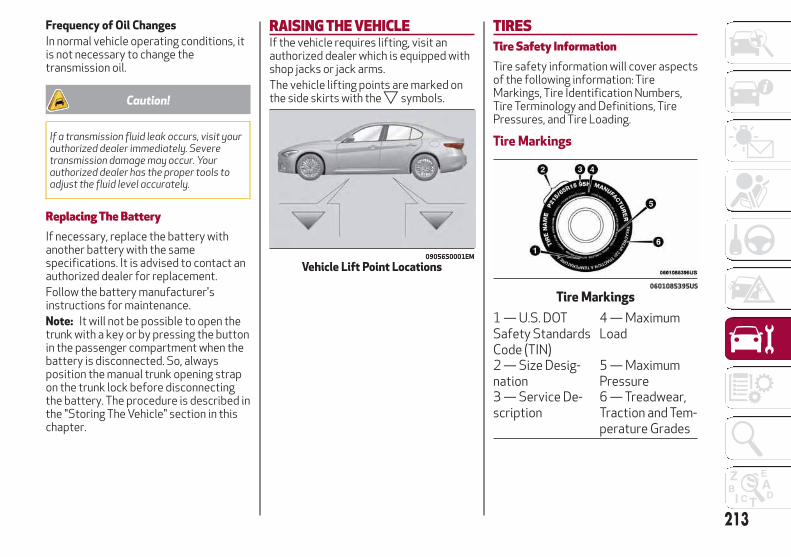
Frequency of Oil Changes
In normal vehicle operating conditions, itis not necessary to change thetransmission oil.
Caution!
If a transmission fluid leak occurs, visit yourauthorized dealer immediately. Severetransmission damage may occur. Yourauthorized dealer has the proper tools toadjust the fluid level accurately.
Replacing The BatteryIf necessary, replace the battery withanother battery with the samespecifications. It is advised to contact anauthorized dealer for replacement.Follow the battery manufacturer'sinstructions for maintenance.Note: It will not be possible to open thetrunk with a key or by pressing the buttonin the passenger compartment when thebattery is disconnected. So, alwaysposition the manual trunk opening strapon the trunk lock before disconnectingthe battery. The procedure is described inthe "Storing The Vehicle" section in thischapter.
RAISING THE VEHICLEIf the vehicle requires lifting, visit anauthorized dealer which is equipped withshop jacks or jack arms.The vehicle lifting points are marked onthe side skirts with the symbols.
TIRESTire Safety InformationTire safety information will cover aspectsof the following information: TireMarkings, Tire Identification Numbers,Tire Terminology and Definitions, TirePressures, and Tire Loading.
Tire Markings
09056S0001EM
Vehicle Lift Point Locations
0601085395US
Tire Markings
1 — U.S. DOTSafety StandardsCode (TIN)
4 — MaximumLoad
2 — Size Desig-nation
5 — MaximumPressure
3 — Service De-scription
6 — Treadwear,Traction and Tem-perature Grades
213

Note:
P (Passenger) — Metric tire sizing isbased on U.S. design standards.P-Metric tires have the letter “P” moldedinto the sidewall preceding the sizedesignation. Example: P215/65R15 95H.
European — Metric tire sizing isbased on European design standards.Tires designed to this standard have thetire size molded into the sidewallbeginning with the section width. Theletter "P" is absent from this tire sizedesignation. Example: 215/65R15 96H.
LT (Light Truck) — Metric tire sizing isbased on U.S. design standards. The sizedesignation for LT-Metric tires is thesame as for P-Metric tires except for theletters “LT” that are molded into thesidewall preceding the size designation.Example: LT235/85R16.
Temporary spare tires are designedfor temporary emergency use only.Temporary high pressure compact sparetires have the letter “T” or “S” moldedinto the sidewall preceding the sizedesignation. Example: T145/80D18 103M.
High flotation tire sizing is based onU.S. design standards and it begins withthe tire diameter molded into thesidewall. Example: 31x10.5 R15 LT.
214
SE
RV
ICIN
GA
ND
MA
INT
EN
AN
CE

Tire Sizing Chart
EXAMPLE:
Example Size Designation: P215/65R15XL 95H, 215/65R15 96H, LT235/85R16C, T145/80D18 103M, 31x10.5 R15 LT
P = Passenger car tire size based on U.S. design standards, or
"....blank...." = Passenger car tire based on European design standards, or
LT = Light truck tire based on U.S. design standards, or
T or S = Temporary spare tire or
31 = Overall diameter in inches (in)
215, 235, 145 = Section width in millimeters (mm)
65, 85, 80 = Aspect ratio in percent (%)
Ratio of section height to section width of tire, or
10.5 = Section width in inches (in)
R = Construction code
"R" means radial construction, or
"D" means diagonal or bias construction
15, 16, 18 = Rim diameter in inches (in)
Service Description:
95 = Load Index
A numerical code associated with the maximum load a tire can carry
H = Speed Symbol
A symbol indicating the range of speeds at which a tire can carry a load corresponding to its load index under certain operating conditions
The maximum speed corresponding to the speed symbol should only be achieved under specified operating conditions (i.e., tire pressure, vehicleloading, road conditions, and posted speed limits)
215
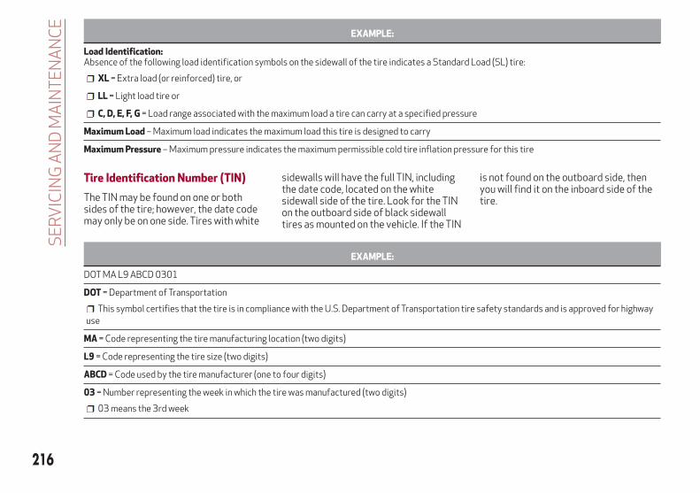
EXAMPLE:
Load Identification:Absence of the following load identification symbols on the sidewall of the tire indicates a Standard Load (SL) tire:
XL = Extra load (or reinforced) tire, or
LL = Light load tire or
C, D, E, F, G = Load range associated with the maximum load a tire can carry at a specified pressure
Maximum Load – Maximum load indicates the maximum load this tire is designed to carry
Maximum Pressure – Maximum pressure indicates the maximum permissible cold tire inflation pressure for this tire
Tire Identification Number (TIN)
The TIN may be found on one or bothsides of the tire; however, the date codemay only be on one side. Tires with white
sidewalls will have the full TIN, includingthe date code, located on the whitesidewall side of the tire. Look for the TINon the outboard side of black sidewalltires as mounted on the vehicle. If the TIN
is not found on the outboard side, thenyou will find it on the inboard side of thetire.
EXAMPLE:
DOT MA L9 ABCD 0301
DOT = Department of Transportation
This symbol certifies that the tire is in compliance with the U.S. Department of Transportation tire safety standards and is approved for highwayuse
MA = Code representing the tire manufacturing location (two digits)
L9 = Code representing the tire size (two digits)
ABCD = Code used by the tire manufacturer (one to four digits)
03 = Number representing the week in which the tire was manufactured (two digits)
03 means the 3rd week
216
SE
RV
ICIN
GA
ND
MA
INT
EN
AN
CE

EXAMPLE:
01 = Number representing the year in which the tire was manufactured (two digits)
01 means the year 2001
Prior to July 2000, tire manufacturers were only required to have one number to represent the year in which the tire was manufactured. Example:031 could represent the 3rd week of 1981 or 1991
Tire Terminology And Definitions
Term Definition
B-Pillar The vehicle B-Pillar is the structural member of the body located behind the front door.
Cold Tire Inflation Pressure
Cold tire inflation pressure is defined as the tire pressure after the vehicle has not beendriven for at least three hours, or driven less than 1 mile (1.6 km) after sitting for aminimum of three hours. Inflation pressure is measured in units of PSI (pounds persquare inch) or kPa (kilopascals).
Maximum Inflation PressureThe maximum inflation pressure is the maximum permissible cold tire inflationpressure for this tire. The maximum inflation pressure is molded into the sidewall.
Recommended Cold Tire Inflation PressureVehicle manufacturer's recommended cold tire inflation pressure as shown on the tireplacard.
Tire PlacardA label permanently attached to the vehicle describing the vehicle’s loading capacity,the original equipment tire sizes and the recommended cold tire inflation pressures.
217

Tire Loading And Tire PressureNote: The proper cold tire inflationpressure is listed on the driver’s sideB-Pillar or the rear edge of the driver'sside door.
Tire And Loading Information Placard
This placard tells you importantinformation about the:
1. Number of people that can be carriedin the vehicle.
2. Total weight your vehicle can carry.
3. Tire size designed for your vehicle.
4. Cold tire inflation pressures for thefront, rear, and spare tires.
Loading
The vehicle maximum load on the tiremust not exceed the load carryingcapacity of the tire on your vehicle. Youwill not exceed the tire's load carryingcapacity if you adhere to the loadingconditions, tire size, and cold tireinflation pressures specified on the Tireand Loading Information placard in“Vehicle Loading” in the “Starting AndOperating” section of this manual.
Note: Under a maximum loaded vehiclecondition, gross axle weight ratings(GAWRs) for the front and rear axlesmust not be exceeded. For furtherinformation on GAWRs, vehicle loading,and trailer towing, refer to “VehicleLoading” in the “Starting And Operating”section of this manual.To determine the maximum loadingconditions of your vehicle, locate thestatement “The combined weight ofoccupants and cargo should neverexceed XXX kg or XXX lbs” on the Tireand Loading Information placard. Thecombined weight of occupants,cargo/luggage and trailer tongue weight(if applicable) should never exceed theweight referenced here.
Steps For Determining Correct LoadLimit—
(1) Locate the statement “Thecombined weight of occupants andcargo should never exceed XXX kg orXXX lbs.” on your vehicle's placard.
(2) Determine the combined weightof the driver and passengers that willbe riding in your vehicle.
(3) Subtract the combined weight ofthe driver and passengers from XXXkg or XXX lbs.
(4) The resulting figure equals theavailable amount of cargo andluggage load capacity. For example,
0806115150US
Example Tire Placard Location (Door)
0806115151US
Example Tire Placard Location (B-Pillar)
GUID-054900418-high.tif
Tire And Loading Information Placard
218
SE
RV
ICIN
GA
ND
MA
INT
EN
AN
CE
if “XXX” amount equals 1400 lbs. andthere will be five 150 lb passengersin your vehicle, the amount ofavailable cargo and luggage loadcapacity is 650 lbs. (1400-750(5x150) = 650 lbs.)
(5) Determine the combined weightof luggage and cargo being loaded onthe vehicle. That weight may notsafely exceed the available cargo andluggage load capacity calculated inStep 4.
(6) If your vehicle will be towing atrailer, load from your trailer will betransferred to your vehicle. Consultthis manual to determine how thisreduces the available cargo andluggage load capacity of your vehicle.
Metric Example For Load Limit
For example, if “XXX” amount equals635 kg and there will be five 68 kgpassengers in your vehicle, the amount ofavailable cargo and luggage load capacityis 295 kg (635-340 (5x68) = 295 kg) asshown in step 4.
Note:
If your vehicle will be towing a trailer,load from your trailer will be transferredto your vehicle. The following tableshows examples on how to calculatetotal load, cargo/luggage, and towingcapacities of your vehicle with varyingseating configurations and number andsize of occupants. This table is forillustration purposes only and may notbe accurate for the seating and loadcarry capacity of your vehicle.
For the following example, thecombined weight of occupants andcargo should never exceed 865 lbs(392 kg).
219

Warning!
Overloading of your tires is dangerous. Overloading can cause tire failure, affect vehicle handling, and increase your stopping distance. Use tires ofthe recommended load capacity for your vehicle. Never overload them.
GUID-054900419-high.tif
220
SE
RV
ICIN
GA
ND
MA
INT
EN
AN
CE

Tires — General Information
Tire Pressure
Proper tire inflation pressure is essentialto the safe and satisfactory operation ofyour vehicle. Four primary areas areaffected by improper tire pressure:
Safety and Vehicle Stability
Economy
Tread Wear
Ride Comfort
Safety
Warning!
Improperly inflated tires are dangerousand can cause collisions.
Underinflation increases tire flexing andcan result in overheating and tire failure.
Overinflation reduces a tire's ability tocushion shock. Objects on the road andchuckholes can cause damage that result intire failure.
Overinflated or underinflated tires canaffect vehicle handling and can failsuddenly, resulting in loss of vehicle control.
Unequal tire pressures can cause steeringproblems. You could lose control of yourvehicle.
Unequal tire pressures from one side ofthe vehicle to the other can cause thevehicle to drift to the right or left.
Always drive with each tire inflated to therecommended cold tire inflation pressure.
Both under-inflation and over-inflationaffect the stability of the vehicle and canproduce a feeling of sluggish response orover responsiveness in the steering.
Note:
Unequal tire pressures from side toside may cause erratic andunpredictable steering response.
Unequal tire pressure from side toside may cause the vehicle to drift left orright.
Fuel Economy
Underinflated tires will increase tirerolling resistance resulting in higher fuelconsumption.Tread Wear
Improper cold tire inflation pressures cancause abnormal wear patterns andreduced tread life, resulting in the needfor earlier tire replacement.Ride Comfort And Vehicle Stability
Proper tire inflation contributes to acomfortable ride. Over-inflationproduces a jarring and uncomfortableride.
Tire Inflation Pressures
The proper cold tire inflation pressure islisted on the driver's side B-Pillar or rearedge of the driver's side door.
At least once a month:
Check and adjust tire pressure with agood quality pocket-type pressure gauge.Do not make a visual judgement whendetermining proper inflation. Tires maylook properly inflated even when they areunder-inflated.
Inspect tires for signs of tire wear orvisible damage.
Caution!
After inspecting or adjusting the tirepressure, always reinstall the valve stemcap. This will prevent moisture and dirt fromentering the valve stem, which coulddamage the valve stem.
Inflation pressures specified on theplacard are always “cold tire inflationpressure”. Cold tire inflation pressure isdefined as the tire pressure after thevehicle has not been driven for at leastthree hours, or driven less than 1 mile(1.6 km) after sitting for a minimum ofthree hours. The cold tire inflationpressure must not exceed the maximuminflation pressure molded into the tiresidewall.Check tire pressures more often ifsubject to a wide range of outdoortemperatures, as tire pressures vary withtemperature changes.
221
Tire pressures change by approximately1 psi (7 kPa) per 12°F (7°C) of airtemperature change. Keep this in mindwhen checking tire pressure inside agarage, especially in the Winter.Example: If garage temperature = 68°F(20°C) and the outside temperature =32°F (0°C) then the cold tire inflationpressure should be increased by 3 psi(21 kPa), which equals 1 psi (7 kPa) forevery 12°F (7°C) for this outsidetemperature condition.Tire pressure may increase from 2 to6 psi (13 to 40 kPa) during operation. DONOT reduce this normal pressure build upor your tire pressure will be too low.
Tire Pressures For High SpeedOperation
The manufacturer advocates driving atsafe speeds and within posted speedlimits. Where speed limits or conditionsare such that the vehicle can be driven athigh speeds, maintaining correct tireinflation pressure is very important.Increased tire pressure and reduced
vehicle loading may be required forhigh-speed vehicle operation. Refer toyour authorized tire dealer or originalequipment vehicle dealer forrecommended safe operating speeds,loading and cold tire inflation pressures.
Warning!
High speed driving with your vehicle undermaximum load is dangerous. The addedstrain on your tires could cause them to fail.You could have a serious collision. Do notdrive a vehicle loaded to the maximumcapacity at continuous speeds above75 mph (120 km/h).
Recommended Cold Tire InflationPressures
For vehicle speeds below 100 mph(160 km/h), recommended cold tireinflation pressures are listed on the TireAnd Loading Information Placard locatedon driver’s side B-Pillar or the rear edgeof the driver's side door.
When driving at speeds 100 mph(160 km/h) and above, increased tirepressures and reduced vehicle loadingare required for high-speed vehicleoperation.For driving speeds above 100 mph(160 km/h) recommended cold tireinflation pressures are listed belowunder "High Speed Tire InflationPressure". Vehicle loading condition mustnot exceed 688 lbs. (312 kg) (driver +three passengers + 88 lbs. (40kg)luggage).
Warning!
High speed driving with your vehicle undermaximum load is dangerous. The addedstrain on your tires could cause them to fail.You could have a serious collision.
222
SE
RV
ICIN
GA
ND
MA
INT
EN
AN
CE
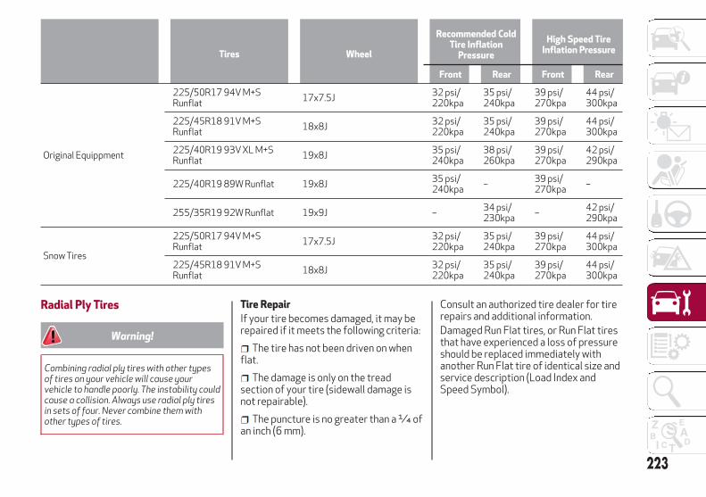
Tires Wheel
Recommended ColdTire Inflation
Pressure
High Speed TireInflation Pressure
Front Rear Front Rear
Original Equippment
225/50R17 94V M+SRunflat
17x7.5J32 psi/220kpa
35 psi/240kpa
39 psi/270kpa
44 psi/300kpa
225/45R18 91V M+SRunflat
18x8J32 psi/220kpa
35 psi/240kpa
39 psi/270kpa
44 psi/300kpa
225/40R19 93V XL M+SRunflat
19x8J35 psi/240kpa
38 psi/260kpa
39 psi/270kpa
42 psi/290kpa
225/40R19 89W Runflat 19x8J35 psi/240kpa
–39 psi/270kpa
–
255/35R19 92W Runflat 19x9J –34 psi/230kpa
–42 psi/290kpa
Snow Tires
225/50R17 94V M+SRunflat
17x7.5J32 psi/220kpa
35 psi/240kpa
39 psi/270kpa
44 psi/300kpa
225/45R18 91V M+SRunflat
18x8J32 psi/220kpa
35 psi/240kpa
39 psi/270kpa
44 psi/300kpa
Radial Ply Tires
Warning!
Combining radial ply tires with other typesof tires on your vehicle will cause yourvehicle to handle poorly. The instability couldcause a collision. Always use radial ply tiresin sets of four. Never combine them withother types of tires.
Tire Repair
If your tire becomes damaged, it may berepaired if it meets the following criteria:
The tire has not been driven on whenflat.
The damage is only on the treadsection of your tire (sidewall damage isnot repairable).
The puncture is no greater than a ¼ ofan inch (6 mm).
Consult an authorized tire dealer for tirerepairs and additional information.Damaged Run Flat tires, or Run Flat tiresthat have experienced a loss of pressureshould be replaced immediately withanother Run Flat tire of identical size andservice description (Load Index andSpeed Symbol).
223

Run Flat Tires — If Equipped
Run Flat tires allow you the capability todrive 50 miles (80 km) at 50 mph(80 km/h) after a rapid loss of inflationpressure. This rapid loss of inflation isreferred to as the Run Flat mode. A RunFlat mode occurs when the tire inflationpressure is of/or below 14 psi (96 kPa).Once a Run Flat tire reaches the run flatmode it has limited driving capabilitiesand needs to be replaced immediately. ARun Flat tire is not repairable.It is not recommended driving a vehicleloaded at full capacity or to tow a trailerwhile a tire is in the run flat mode.See the tire pressure monitoring sectionfor more information.
Tire Spinning
When stuck in mud, sand, snow, or iceconditions, do not spin your vehicle'swheels above 30 mph (48 km/h) or forlonger than 30 seconds continuouslywithout stopping.
Warning!
Fast spinning tires can be dangerous. Forcesgenerated by excessive wheel speeds maycause tire damage or failure. A tire couldexplode and injure someone. Do not spinyour vehicle's wheels faster than 30 mph(48 km/h) for more than 30 secondscontinuously when you are stuck, and do notlet anyone near a spinning wheel, no matterwhat the speed.
Tread Wear Indicators
Tread wear indicators are in the originalequipment tires to help you indetermining when your tires should bereplaced.
These indicators are molded into thebottom of the tread grooves. They willappear as bands when the tread depth
becomes a 1/16 of an inch (1.6 mm).When the tread is worn to the tread wearindicators, the tire should be replaced.Refer to “Replacement Tires” in thissection for further information.
Life Of Tire
The service life of a tire is dependentupon varying factors including, but notlimited to:
Driving style.
Tire pressure - Improper cold tireinflation pressures can cause unevenwear patterns to develop across the tiretread. These abnormal wear patterns willreduce tread life, resulting in the need forearlier tire replacement.
Distance driven.
Performance tires, tires with a speedrating of V or higher, and Summer tirestypically have a reduced tread life.Rotation of these tires per the vehiclescheduled maintenance is highlyrecommended.
Warning!
Tires and the spare tire should be replacedafter six years, regardless of the remainingtread. Failure to follow this warning canresult in sudden tire failure. You could losecontrol and have a collision resulting inserious injury or death.
0806104865NA
Tire Tread
1 — Worn Tire2 — New Tire
224
SE
RV
ICIN
GA
ND
MA
INT
EN
AN
CE
Keep dismounted tires in a cool, dry placewith as little exposure to light aspossible. Protect tires from contact withoil, grease, and gasoline.
Replacement Tires
The tires on your new vehicle provide abalance of many characteristics. Theyshould be inspected regularly for wearand correct cold tire inflation pressures.The manufacturer strongly recommendsthat you use tires equivalent to theoriginals in size, quality and performancewhen replacement is needed. Refer to theparagraph on “Tread Wear Indicators” inthis section. Refer to the Tire and LoadingInformation placard or the VehicleCertification Label for the sizedesignation of your tire. The Load Indexand Speed Symbol for your tire will befound on the original equipment tiresidewall.See the Tire Sizing Chart example foundin the “Tire Safety Information” section ofthis manual for more information relatingto the Load Index and Speed Symbol of atire.It is recommended to replace the twofront tires or two rear tires as a pair.Replacing just one tire can seriouslyaffect your vehicle’s handling. If you everreplace a wheel, make sure that thewheel’s specifications match those of theoriginal wheels.It is recommended you contact yourauthorized tire dealer or original
equipment dealer with any questions youmay have on tire specifications orcapability. Failure to use equivalentreplacement tires may adversely affectthe safety, handling, and ride of yourvehicle.
Warning!
Do not use a tire, wheel size, load rating,or speed rating other than that specified foryour vehicle. Some combinations ofunapproved tires and wheels may changesuspension dimensions and performancecharacteristics, resulting in changes tosteering, handling, and braking of yourvehicle. This can cause unpredictablehandling and stress to steering andsuspension components. You could losecontrol and have a collision resulting inserious injury or death. Use only the tire andwheel sizes with load ratings approved foryour vehicle.
Never use a tire with a smaller load indexor capacity, other than what was originallyequipped on your vehicle. Using a tire with asmaller load index could result in tireoverloading and failure. You could losecontrol and have a collision.
Failure to equip your vehicle with tireshaving adequate speed capability can resultin sudden tire failure and loss of vehiclecontrol.
Caution!
Replacing original tires with tires of adifferent size may result in falsespeedometer and odometer readings.
Spare Tires — If EquippedNote: For vehicles equipped with TireRepair Kit instead of a spare tire, pleaserefer to “Tire Repair Kit” in “In Case OfEmergency” for further information.
Caution!
Because of the reduced ground clearance,do not take your vehicle through anautomatic car wash with a compact orlimited use temporary spare installed.Damage to the vehicle may result.
Spare Tire Matching OriginalEquipped Tire And Wheel —If Equipped
Your vehicle may be equipped with aspare tire and wheel equivalent in lookand function to the original equipmenttire and wheel found on the front or rearaxle of your vehicle. This spare tire maybe used in the tire rotation for yourvehicle. If your vehicle has this option,refer to an authorized tire dealer for therecommended tire rotation pattern.
225

Compact Spare Tire — If Equipped
The compact spare is for temporaryemergency use only. You can identify ifyour vehicle is equipped with a compactspare by looking at the spare tiredescription on the Tire and LoadingInformation Placard located on thedriver’s side door opening or on thesidewall of the tire. Compact spare tiredescriptions begin with the letter “T” or“S” preceding the size designation.Example: T145/80D18 103M.T, S = Temporary Spare TireSince this tire has limited tread life, theoriginal equipment tire should berepaired (or replaced) and reinstalled onyour vehicle at the first opportunity.Do not install a wheel cover or attempt tomount a conventional tire on the compactspare wheel, since the wheel is designedspecifically for the compact spare tire.Do not install more than one compactspare tire and wheel on the vehicle at anygiven time.
Warning!
Compact and collapsible spares are fortemporary emergency use only. With thesespares, do not drive more than 50 mph(80 km/h). Temporary use spares havelimited tread life. When the tread is worn tothe tread wear indicators, the temporary usespare tire needs to be replaced. Be sure tofollow the warnings, which apply to yourspare. Failure to do so could result in sparetire failure and loss of vehicle control.
Full Size Spare — If Equipped
The full size spare is for temporaryemergency use only. This tire may looklike the originally equipped tire on thefront or rear axle of your vehicle, but it isnot. This spare tire may have limitedtread life. When the tread is worn to thetread wear indicators, the temporary usefull size spare tire needs to be replaced.Since it is not the same as your originalequipment tire, replace (or repair) theoriginal equipment tire and reinstall onthe vehicle at the first opportunity.
Limited Use Spare — If Equipped
The limited use spare tire is fortemporary emergency use only. This tireis identified by a label located on thelimited use spare wheel. This labelcontains the driving limitations for thisspare. This tire may look like the original
equipped tire on the front or rear axle ofyour vehicle, but it is not. Installation ofthis limited use spare tire affects vehiclehandling. Since it is not the same as youroriginal equipment tire, replace (orrepair) the original equipment tire andreinstall on the vehicle at the firstopportunity.
Warning!
Limited use spares are for emergency useonly. Installation of this limited use sparetire affects vehicle handling. With this tire,do not drive more than the speed listed onthe limited use spare wheel. Keep inflated tothe cold tire inflation pressures listed onyour Tire and Loading Information Placardlocated on the driver’s side B-Pillar or therear edge of the driver’s side door. Replace(or repair) the original equipment tire at thefirst opportunity and reinstall it on yourvehicle. Failure to do so could result in loss ofvehicle control.
Wheel And Wheel Trim CareAll wheels and wheel trim, especiallyaluminum and chrome plated wheels,should be cleaned regularly using mild(neutral Ph) soap and water to maintaintheir luster and to prevent corrosion.Wash wheels with the same soap solutionrecommended for the body of thevehicle.Your wheels are susceptible todeterioration caused by salt, sodium226
SE
RV
ICIN
GA
ND
MA
INT
EN
AN
CE
chloride, magnesium chloride, calciumchloride, etc., and other road chemicalsused to melt ice or control dust on dirtroads. Use a soft cloth or sponge and mildsoap to wipe away promptly. Do not useharsh chemicals or a stiff brush. They candamage the wheel’s protective coatingthat helps keep them from corroding andtarnishing.
Caution!
Avoid products or automatic car washesthat use acidic solutions or strong alkalineadditives or harsh brushes. Manyaftermarket wheel cleaners and automaticcar washes may damage the wheel'sprotective finish. Such damage is notcovered by the New Vehicle LimitedWarranty. Only car wash soap, Mopar WheelCleaner or equivalent is recommended.
When cleaning extremely dirty wheelsincluding excessive brake dust, care mustbe taken in the selection of tire and wheelcleaning chemicals and equipment toprevent damage to the wheels. MoparWheel Treatment or Mopar ChromeCleaner or their equivalent isrecommended or select a non-abrasive,non-acidic cleaner for aluminum orchrome wheels.
Caution!
Do not use scouring pads, steel wool, abristle brush, metal polishes or oven cleaner.These products may damage the wheel'sprotective finish. Such damage is notcovered by the New Vehicle LimitedWarranty. Only car wash soap, Mopar WheelCleaner or equivalent is recommended.
Note: If you intend parking or storingyour vehicle for an extended period aftercleaning the wheels with wheel cleaner,drive your vehicle and apply the brakes toremove the water droplets from thebrake components. This activity willremove the red rust on the brake rotorsand prevent vehicle vibration whenbraking.Dark Vapor Chrome, Black SatinChrome, or Low Gloss Clear Coat Wheels
Caution!
If your vehicle is equipped with thesespecialty wheels, DO NOT USE wheelcleaners, abrasives, or polishing compounds.They will permanently damage this finishand such damage is not covered by the NewVehicle Limited Warranty. HAND WASHONLY USING MILD SOAP AND WATER WITHA SOFT CLOTH. Used on a regular basis; thisis all that is required to maintain this finish.
Tire Types
All Season Tires — If Equipped
All Season tires provide traction for allseasons (Spring, Summer, Fall, andWinter). Traction levels may varybetween different all season tires. Allseason tires can be identified by the M+S,M&S, M/S or MS designation on the tiresidewall. Use all season tires only in setsof four; failure to do so may adverselyaffect the safety and handling of yourvehicle.
Summer Or Three Season Tires —If Equipped
Summer tires provide traction in bothwet and dry conditions, and are notintended to be driven in snow or on ice. Ifyour vehicle is equipped with Summertires, be aware these tires are notdesigned for Winter or cold drivingconditions. Install Winter tires on yourvehicle when ambient temperatures areless than 40°F (5°C) or if roads arecovered with ice or snow. For moreinformation, contact an authorizeddealer.Summer tires do not contain the allseason designation or mountain/snowflake symbol on the tire sidewall.Use Summer tires only in sets of four;failure to do so may adversely affect thesafety and handling of your vehicle.
227

Warning!
Do not use Summer tires in snow/iceconditions. You could lose vehicle control,resulting in severe injury or death. Drivingtoo fast for conditions also creates thepossibility of loss of vehicle control.
Snow Tires
Some areas of the country require theuse of snow tires during the Winter. Snowtires can be identified by a“mountain/snowflake” symbol on the tiresidewall.
If you need snow tires,select tires equivalentin size and type to theoriginal equipmenttires. Use snow tiresonly in sets of four;failure to do so may
adversely affect the safety and handlingof your vehicle.Snow tires generally have lower speedratings than what was originally equippedwith your vehicle and should not beoperated at sustained speeds over75 mph (120 km/h). For speeds above75 mph (120 km/h) refer to originalequipment or an authorized tire dealerfor recommended safe operating speeds,loading and cold tire inflation pressures.
While studded tires improveperformance on ice, skid and tractioncapability on wet or dry surfaces may bepoorer than that of non-studded tires.Some states prohibit studded tires;therefore, local laws should be checkedbefore using these tire types.
Tire Chains (Traction Devices)Use of traction devices require sufficienttire-to-body clearance. Follow theserecommendations to guard againstdamage.
Note:
Traction device must be of propersize for the tire, as recommended by thetraction device manufacturer
Use on Rear Tires Only
Due to limited clearance, thefollowing traction devices arerecommended:
For a 255/35R19 tire, use of a snowtraction device with a maximumprojection of 7 mm beyond the tireprofile is recommended.
For 225/50R17, 225/45R18 or225/40R19 tires, use of a snow tractiondevice with a maximum projection of9 mm beyond the tire profile isrecommended.
Caution!
To avoid damage to your vehicle or tires,observe the following precautions:
Because of restricted traction deviceclearance between tires and othersuspension components, it is important thatonly traction devices in good condition areused. Broken devices can cause seriousdamage. Stop the vehicle immediately ifnoise occurs that could indicate devicebreakage. Remove the damaged parts ofthe device before further use.
Install device as tightly as possible andthen retighten after driving about ½ mile(0.8 km).
Do not exceed 30 mph (48 km/h).
Drive cautiously and avoid severe turnsand large bumps, especially with a loadedvehicle.
Do not drive for a prolonged period on drypavement.
Observe the traction devicemanufacturer’s instructions on the methodof installation, operating speed, andconditions for use. Always use thesuggested operating speed of the devicemanufacturer’s if it is less than 30 mph(48 km/h).
Do not use traction devices on a compactspare tire.
228
SE
RV
ICIN
GA
ND
MA
INT
EN
AN
CE

Tire Rotation RecommendationsTires on the front and rear axles ofvehicles operate at different loads andperform different steering, driving, andbraking functions. For these reasons,they wear at unequal rates. These effectscan be reduced by timely rotation oftires. Rotation will increase tread life,maintain traction levels and contribute toa smooth, quiet ride.To resolve this problem, tires should berotated at each service interval(approximately every 10,000 miles[16,000km]). More frequent rotation ispermissible if desired. The reasons forany rapid or unusual wear should becorrected prior to rotation beingperformed.Tire Rotations Not Recommended —If Equipped
Due to different size tires and wheels onfront and rear axles tire rotation is notpossible for:
2.0T GME Engine Equipped with a225/40R19 front and 255/35R19 reartires.
Caution!
Damage to the vehicle may occur if225/40R19 front and 255/35R19 reartires are rotated
Tire rotation contributes to thepreservation of the grip and tractionperformance on wet, muddy or snowyroads, guaranteeing optimal driveabilityof the vehicle.In the case of irregular wear of the tiresidentify the cause and correct it as soonas possible, by contacting an authorizeddealer.Tire Rotation for Directional Tires —If Equipped
Directional tires are equipped on thefollowing:
2.0T GME Engine equipped with samesize tires and wheels on front and rearaxles
The rotational direction of the tire mustbe taken into consideration whenrotating the tires. The recommendedrotation pattern for directional tires isshown below.
All Wheel Drive (AWD) Models
It is recommended to avoid situationswith a large difference in wear betweenthe front and rear tires and to strictly usewinter tires of the sizes given on the tireplacard.The AWD system and the original tiresare developed together to ensure thevehicle’s best performance. Whenchanging the tires, it is recommended tous the same “AR” marked tires, tomaintain the same level of performanceand component life.
09066S0002EM
Tire Rotation
229
DEPARTMENT OFTRANSPORTATION UNIFORMTIRE QUALITY GRADESThe following tire grading categorieswere established by the NationalHighway Traffic SafetyAdministration. The specific graderating assigned by the tire'smanufacturer in each category isshown on the sidewall of the tires onyour vehicle.
All passenger vehicle tires mustconform to Federal safetyrequirements in addition to thesegrades.
Treadwear
The Treadwear grade is acomparative rating, based on thewear rate of the tire when testedunder controlled conditions on aspecified government test course.For example, a tire graded 150 wouldwear one and one-half times as wellon the government course as a tiregraded 100. The relativeperformance of tires depends uponthe actual conditions of their use,however, and may departsignificantly from the norm due tovariations in driving habits, service
practices, and differences in roadcharacteristics and climate.
Traction Grades
The Traction grades, from highest tolowest, are AA, A, B, and C. Thesegrades represent the tire's ability tostop on wet pavement, as measuredunder controlled conditions onspecified government test surfacesof asphalt and concrete. A tiremarked C may have poor tractionperformance.
Warning!
The traction grade assigned to thistire is based on straight-aheadbraking traction tests, and does notinclude acceleration, cornering,hydroplaning, or peak tractioncharacteristics.
Temperature Grades
The temperature grades are A (thehighest), B, and C, representing thetire's resistance to the generation ofheat and its ability to dissipate heat,when tested under controlledconditions on a specified indoor
laboratory test wheel. Sustained hightemperature can cause the materialof the tire to degenerate and reducetire life, and excessive temperaturecan lead to sudden tire failure. Thegrade C corresponds to a level ofperformance, which all passengervehicle tires must meet under theFederal Motor Vehicle SafetyStandard No. 109. Grades B and Arepresent higher levels ofperformance on the laboratory testwheel, than the minimum required bylaw.
Warning!
The temperature grade for this tireis established for a tire that isproperly inflated and notoverloaded. Excessive speed,under-inflation, or excessiveloading, either separately or incombination, can cause heatbuildup and possible tire failure.
230
SE
RV
ICIN
GA
ND
MA
INT
EN
AN
CE

STORING THE VEHICLEIf the vehicle is left inactive for longerthan a month, the following precautionsshould be observed:
Park the vehicle in an area that iscovered and dry, and well-ventilated ifpossible. Slightly open the windows.
Check that the electric park brake isnot activated.
Carry out the procedure: “manual trunkopening device” procedure described inthis paragraph.
Disconnect the negative batteryterminal and check the battery charge.Repeat this check once every threemonths during storage.
If the battery is not disconnected fromthe electrical system, check its state ofcharge every thirty days.
Clean and protect the painted partsusing protective wax.
Clean and protect the shiny metalparts using special compounds availablecommercially.
Sprinkle talcum powder on thewindshield wiper rubber blades, and liftthem off the glass.
Cover the vehicle with a fabric orperforated plastic sheet, payingparticular care not to damage the paintedsurface by dragging any dust that mayhave accumulated on it. Do not usecompact plastic sheets, as they do notallow humidity to evaporate from thesurface of the vehicle.
Inflate tires to +7.25 psi (+0.5 bar)above the standard prescribed pressureand check it periodically.
Do not drain the engine coolingsystem.
Any time the vehicle is left inactive fortwo weeks or more, operate the airconditioning system with engine idlingfor at least five minutes, setting externalair and with fan set to maximum speed.This operation will ensure appropriatelubrication for the system, thusminimizing the possibility of damage tothe compressor when the system isoperated again.
Note: After cycling the ignition to STOPand having closed the driver side door,wait at least one minute beforedisconnecting the electrical supply fromthe battery. When reconnecting theelectrical supply to the battery, makesure that the ignition is in the STOPposition and the driver side door isclosed.
Manual Trunk Opening Device
Proceed as follows if the battery needsto be disconnected:
1. From the trunk interior covering,rotate the plug to the left of the lock andextract the strap connected to it.
2. Make sure the free end of the strapremains outside the deck lid when closingthe deck lid.
3. The trunk can now be openedmanually by pulling the strap.Note: This procedure must be carriedout exclusively in safe places because itallows to open the trunk unconditionally.
09086S0001EM
Trunk Compartment
231
BODYWORKProtection Against AtmosphericAgentsThe vehicle is equipped with the bestavailable technological solutions toprotect the bodywork against corrosion.These include:
Painting products and systems whichgive the vehicle resistance to corrosionand abrasion.
Use of galvanized (or pre-treated)steel sheets, with high resistance tocorrosion.
Spraying of plastic parts, with aprotective function in the more exposedpoints: underdoor, inner wing, edges, etc.
Use of “open” boxed sections toprevent condensation and pockets ofmoisture which could favor the formationof rust inside.
Use of special films to protect againstabrasion in exposed areas (e.g. rear wing,doors, etc.).
Corrosion WarrantyYour vehicle is covered by CorrosionWarranty against perforation due to rustof any original element of the structureor bodywork. For the general terms ofthis warranty, refer to the WarrantyBooklet.
Preserving The BodyworkPaint
Touch up abrasions and scratchesimmediately to prevent the formation ofrust.Maintenance of paintwork consists ofwashing the car: the frequency dependson the conditions and environment wherethe car is used. For example, it isadvisable to wash the vehicle more oftenin areas with high levels of atmosphericpollution or salted roads.Some parts of the vehicle may becovered with a matte paint which, inorder to be maintained intact, requiresspecial care.To correctly wash the vehicle, followthese instructions:
If high pressure jets or cleaners areused to wash the vehicle, keep a distanceof at least 15 inches (40 cm) from thebodywork to avoid damage or alteration.Build up of water could cause damage tothe vehicle in the long term.
To make it easier to remove any dirtdeposits in the area where the blades arenormally located it is recommended toposition the windshield wipers vertically(service position), for more information,refer to “Dealer Service” in this chapter.
Wash the bodywork using a lowpressure jet of water if possible.
Wipe a sponge with a slightly soapysolution over the bodywork, frequentlyrinsing the sponge.
Rinse well with water and dry with aleather chamois.
Dry the less visible parts (e.g. doorframes, hood, headlight frames, etc.) withspecial care, as water may stagnate moreeasily in these areas. Do not wash the carafter it has been left in the sun or with thehood hot: this may alter the shine of thepaintwork.Exterior plastic parts must be cleaned inthe same way as the rest of the vehicle.If washing the car in a service that movesthe car, for cars with automatictransmissions, PARK (P) must be cut out.You have to shut off the engine in thefollowing conditions: car stopped,transmission in NEUTRAL (N), push thestarter button for at least three seconds.Note: Avoid parking under trees; theresin dropped by trees makes thepaintwork go opaque and increases thepossibility of corrosion.
232
SE
RV
ICIN
GA
ND
MA
INT
EN
AN
CE

Windows
Use specific detergents and clean clothsto prevent scratching or altering thetransparency.
Caution!
Wipe the rear window inside gently with acloth following the direction of the filamentsto avoid damaging the heating device.
Front Headlights
Use a soft cloth soaked in water anddetergent for washing cars.
Note:
Never use aromatic substances (e.g.gasoline) or ketones (e.g. acetone) forcleaning the plastic lenses of theheadlights.
When cleaning with a pressurewasher, keep the pressure washer atleast eight inches (20 cm) away from theheadlights.
Engine Compartment
At the end of every winter, wash theengine compartment thoroughly, takingcare not to aim the jet of water directly atthe electronic control units or at thewindshield wiper motors. Have thisoperation performed at a specializedworkshop.Note: The washing should take placewith the engine cold and the ignitiondevice in the STOP position. After thewashing operation, make sure that thevarious protections (e.g. rubber caps andguards) have not been removed ordamaged.
INTERIORSPeriodically check the cleanliness of theinterior, beneath the mats, which couldcause oxidation of the sheet metal.
Seats And Fabric PartsRemove dust with a soft brush or avacuum cleaner. It is advised to use amoist brush on velvet upholstery. Rub theseats with a sponge moistened with asolution of water and neutral detergent.
Leather Seats — If EquippedRemove the dry dirt with a chamois orslightly damp cloth, without exerting toomuch pressure.Remove any liquid or grease stains usingan absorbent dry cloth, without rubbing.Then clean with a soft cloth or buckskincloth dampened with water and mildsoap. If the stain persists, use specificproducts and observe the instructionscarefully.Note: Never use alcohol. Make sure thatthe cleaning products used contain noalcohol or alcohol derivatives, even insmall quantities.
233

Plastic And Coated PartsClean interior plastic parts with a dampcloth (if possible made from microfiber),and a solution of water and neutral,non-abrasive detergent.To clean oily or persistent stains, usespecific products free from solvents anddesigned to maintain the originalappearance and color of the components.Remove any dust using a microfibercloth, if necessary moistened with water.The use of paper tissues is notrecommended as these may leaveresidues.
Genuine Leather Parts — If EquippedUse only water and mild soap to cleanthese parts. Never use alcohol oralcohol-based products.Before using a specific product forcleaning interiors, make sure that it doesnot contain alcohol and/or alcohol basedsubstances.
Carbon Fiber PartsTo eliminate small scratches and markson the carbon, contact your authorizeddealer. An improperly performedoperation may irreparably damage thecarbon.
234
SE
RV
ICIN
GA
ND
MA
INT
EN
AN
CE

TECHNICAL SPECIFICATIONS
Everything you may find useful forunderstanding how your vehicle is madeand works is contained in this chapterand illustrated with data, tables andgraphics. For the enthusiasts and thetechnician, but also just for those whowant to know every detail of theirvehicle.
IDENTIFICATION DATA . . . . . . . . .236ENGINE . . . . . . . . . . . . . . . . . .237POWER SUPPLY . . . . . . . . . . . . .238TRANSMISSION . . . . . . . . . . . . .239BRAKES . . . . . . . . . . . . . . . . . .240SUSPENSION . . . . . . . . . . . . . .241STEERING SYSTEM. . . . . . . . . . .242DIMENSIONS. . . . . . . . . . . . . . .243WEIGHTS . . . . . . . . . . . . . . . . .245FUEL REQUIREMENTS . . . . . . . .246FLUID CAPACITIES . . . . . . . . . . .248FLUIDS AND LUBRICANTS . . . . . .249PERFORMANCE . . . . . . . . . . . . .251
235

IDENTIFICATION DATAVehicle Identification NumberThe Vehicle Identification Number (VIN)is stamped on a plate on the front leftcorner of the dashboard cover, which canbe seen from outside the vehicle, throughthe windshield.
This number is also printed on the chassisat the front left shock absorber and canbe seen by opening the enginecompartment hood.
Vehicle Identification Number (VIN)PlateThe plates are located on the left side Apillar and contain the data about:
Chassis number (VIN).
Vehicle type (USA and Canada only).
Color code.
Place of manufacturing of the vehicle(USA and Mexico only).
Vehicle manufacturing date.
Maximum permitted weights.
Permitted tire inflation pressure (USAand Canada only).
10016S0001EM
Vehicle Identification Number
10016S0002EM
Vehicle Identification Number
236
TE
CH
NIC
AL
SP
EC
IFIC
ATIO
NS

ENGINE
2.0 T4 MAir Engine 280 HP
Cycle Four
Number and position of cylinders 4 in line
Piston bore and stroke (mm) 84 / 90
Total displacement (cm³) 1,995
Compression ratio 10:1
Maximum power (SAE) (HP) 280
Maximum power (kW) 209
Corresponding engine speed (rpm) 5200
Maximum torque (SAE) (ft-lb) 306
Maximum torque (Nm) 415
Corresponding engine speed (rpm) 3,300 – 4,400
Fuel87 Octane Minimum, 91 Recommended, ethanol percentage is
0–15%.
237

POWER SUPPLY
Power Supply
2.0L T4 MAir Engine Electronic timed sequential injection with knock control
238
TE
CH
NIC
AL
SP
EC
IFIC
ATIO
NS
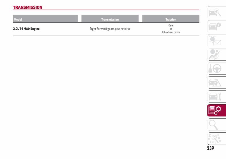
TRANSMISSION
Model Transmission Traction
2.0L T4 MAir Engine Eight forward gears plus reverseRear
orAll-wheel drive
239

BRAKES
Model Front brakes Rear brakes Parking brake
2.0 T4 MAir Engine Disc Disc Electric
Caution!
Water, ice and salt spread on the roads may deposit on the brake discs, reducing braking efficiency the first time the brakes are applied.
To obtain the maximum efficiency of the braking system, a bedding-in period of about 300 miles (500 km) is needed: during this period it isbetter to avoid sharp, repeated and prolonged braking.
240
TE
CH
NIC
AL
SP
EC
IFIC
ATIO
NS
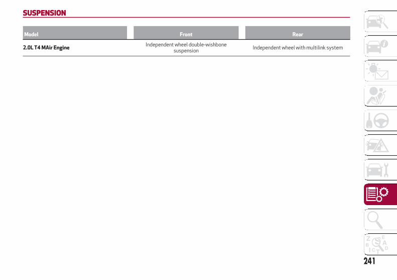
SUSPENSION
Model Front Rear
2.0L T4 MAir EngineIndependent wheel double-wishbone
suspensionIndependent wheel with multilink system
241

STEERING SYSTEM
Model Curb-to-curb turning circle Type
2.0L T4 MAir Engine 35.50 ft (10.80 m)Rack and pinion with electric power
steering
242
TE
CH
NIC
AL
SP
EC
IFIC
ATIO
NS
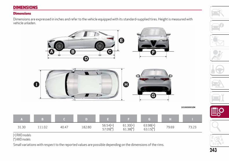
DIMENSIONSDimensionsDimensions are expressed in inches and refer to the vehicle equipped with its standard-supplied tires. Height is measured withvehicle unladen.
A B C D E F G H I
31.30 111.02 40.47 182.8056.54(+)57.09(*)
61.30(+)61.38(*)
63.98(+)63.15(*)
79.69 73.23
(+) RWD models(*) AWD models
Small variations with respect to the reported values are possible depending on the dimensions of the rims.
10106S0001EM
243

Luggage Compartment VolumeCapacity (V.D.A. standards)
Rear seats not folded
Vehicle unladen: 16.96 cubic feet
244
TE
CH
NIC
AL
SP
EC
IFIC
ATIO
NS
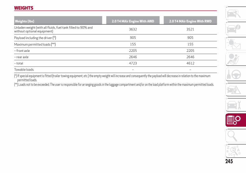
WEIGHTS
Weights (lbs) 2.0 T4 MAir Engine With AWD 2.0 T4 MAir Engine With RWD
Unladen weight (with all fluids, fuel tank filled to 90% andwithout optional equipment)
3632 3521
Payload including the driver (*) 905 905
Maximum permitted loads (**) 155 155
– front axle 2205 2205
– rear axle 2646 2646
– total 4723 4612
Towable loads – –
(*) If special equipment is fitted (trailer towing equipment, etc.) the empty weight will increase and consequently the payload will decrease in relation to the maximumpermitted loads.
(**) Loads not to be exceeded. The user is responsible for arranging goods in the luggage compartment and/or on the load platform within the maximum permitted loads.
245
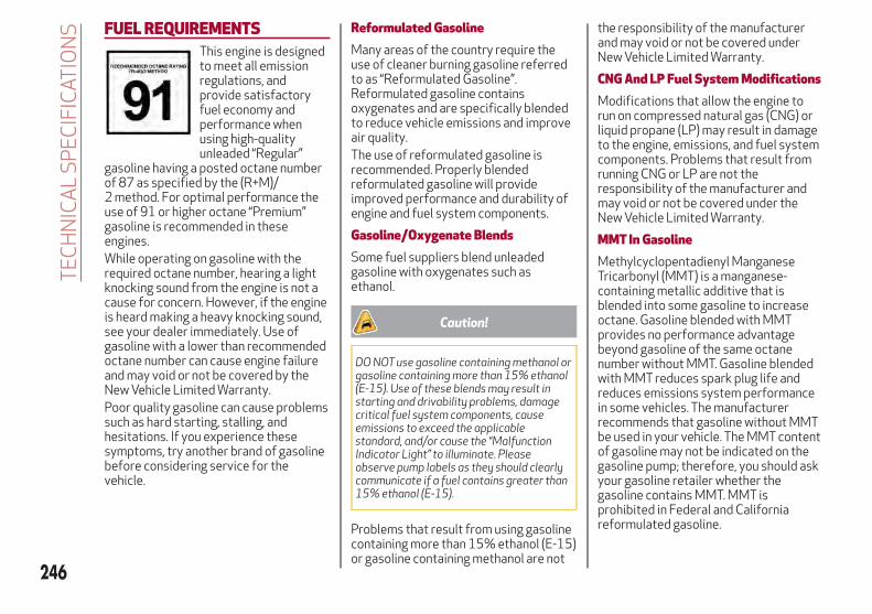
FUEL REQUIREMENTSThis engine is designedto meet all emissionregulations, andprovide satisfactoryfuel economy andperformance whenusing high-qualityunleaded “Regular”
gasoline having a posted octane numberof 87 as specified by the (R+M)/2 method. For optimal performance theuse of 91 or higher octane “Premium”gasoline is recommended in theseengines.While operating on gasoline with therequired octane number, hearing a lightknocking sound from the engine is not acause for concern. However, if the engineis heard making a heavy knocking sound,see your dealer immediately. Use ofgasoline with a lower than recommendedoctane number can cause engine failureand may void or not be covered by theNew Vehicle Limited Warranty.Poor quality gasoline can cause problemssuch as hard starting, stalling, andhesitations. If you experience thesesymptoms, try another brand of gasolinebefore considering service for thevehicle.
Reformulated GasolineMany areas of the country require theuse of cleaner burning gasoline referredto as “Reformulated Gasoline”.Reformulated gasoline containsoxygenates and are specifically blendedto reduce vehicle emissions and improveair quality.The use of reformulated gasoline isrecommended. Properly blendedreformulated gasoline will provideimproved performance and durability ofengine and fuel system components.
Gasoline/Oxygenate BlendsSome fuel suppliers blend unleadedgasoline with oxygenates such asethanol.
Caution!
DO NOT use gasoline containing methanol orgasoline containing more than 15% ethanol(E-15). Use of these blends may result instarting and drivability problems, damagecritical fuel system components, causeemissions to exceed the applicablestandard, and/or cause the “MalfunctionIndicator Light” to illuminate. Pleaseobserve pump labels as they should clearlycommunicate if a fuel contains greater than15% ethanol (E-15).
Problems that result from using gasolinecontaining more than 15% ethanol (E-15)or gasoline containing methanol are not
the responsibility of the manufacturerand may void or not be covered underNew Vehicle Limited Warranty.
CNG And LP Fuel System ModificationsModifications that allow the engine torun on compressed natural gas (CNG) orliquid propane (LP) may result in damageto the engine, emissions, and fuel systemcomponents. Problems that result fromrunning CNG or LP are not theresponsibility of the manufacturer andmay void or not be covered under theNew Vehicle Limited Warranty.
MMT In GasolineMethylcyclopentadienyl ManganeseTricarbonyl (MMT) is a manganese-containing metallic additive that isblended into some gasoline to increaseoctane. Gasoline blended with MMTprovides no performance advantagebeyond gasoline of the same octanenumber without MMT. Gasoline blendedwith MMT reduces spark plug life andreduces emissions system performancein some vehicles. The manufacturerrecommends that gasoline without MMTbe used in your vehicle. The MMT contentof gasoline may not be indicated on thegasoline pump; therefore, you should askyour gasoline retailer whether thegasoline contains MMT. MMT isprohibited in Federal and Californiareformulated gasoline.
246
TE
CH
NIC
AL
SP
EC
IFIC
ATIO
NS
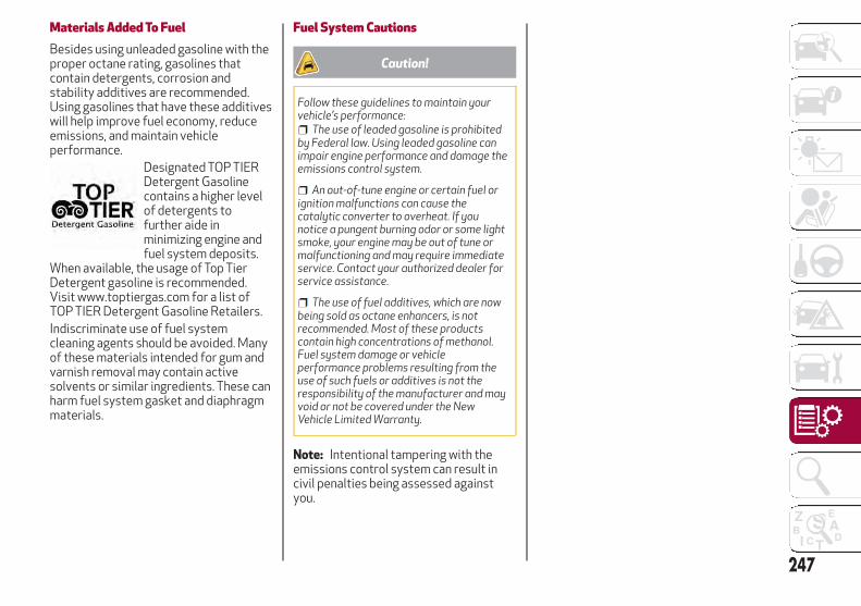
Materials Added To FuelBesides using unleaded gasoline with theproper octane rating, gasolines thatcontain detergents, corrosion andstability additives are recommended.Using gasolines that have these additiveswill help improve fuel economy, reduceemissions, and maintain vehicleperformance.
Designated TOP TIERDetergent Gasolinecontains a higher levelof detergents tofurther aide inminimizing engine andfuel system deposits.
When available, the usage of Top TierDetergent gasoline is recommended.Visit www.toptiergas.com for a list ofTOP TIER Detergent Gasoline Retailers.Indiscriminate use of fuel systemcleaning agents should be avoided. Manyof these materials intended for gum andvarnish removal may contain activesolvents or similar ingredients. These canharm fuel system gasket and diaphragmmaterials.
Fuel System Cautions
Caution!
Follow these guidelines to maintain yourvehicle’s performance:
The use of leaded gasoline is prohibitedby Federal law. Using leaded gasoline canimpair engine performance and damage theemissions control system.
An out-of-tune engine or certain fuel orignition malfunctions can cause thecatalytic converter to overheat. If younotice a pungent burning odor or some lightsmoke, your engine may be out of tune ormalfunctioning and may require immediateservice. Contact your authorized dealer forservice assistance.
The use of fuel additives, which are nowbeing sold as octane enhancers, is notrecommended. Most of these productscontain high concentrations of methanol.Fuel system damage or vehicleperformance problems resulting from theuse of such fuels or additives is not theresponsibility of the manufacturer and mayvoid or not be covered under the NewVehicle Limited Warranty.
Note: Intentional tampering with theemissions control system can result incivil penalties being assessed againstyou.
247
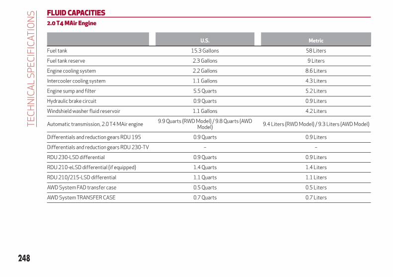
FLUID CAPACITIES2.0 T4 MAir Engine
U.S. Metric
Fuel tank 15.3 Gallons 58 Liters
Fuel tank reserve 2.3 Gallons 9 Liters
Engine cooling system 2.2 Gallons 8.6 Liters
Intercooler cooling system 1.1 Gallons 4.3 Liters
Engine sump and filter 5.5 Quarts 5.2 Liters
Hydraulic brake circuit 0.9 Quarts 0.9 Liters
Windshield washer fluid reservoir 1.1 Gallons 4.2 Liters
Automatic transmission, 2.0 T4 MAir engine9.9 Quarts (RWD Model) / 9.8 Quarts (AWD
Model)9.4 Liters (RWD Model) / 9.3 Liters (AWD Model)
Differentials and reduction gears RDU 195 0.9 Quarts 0.9 Liters
Differentials and reduction gears RDU 230-TV – –
RDU 230-LSD differential 0.9 Quarts 0.9 Liters
RDU 210-eLSD differential (if equipped) 1.4 Quarts 1.4 Liters
RDU 210/215-LSD differential 1.1 Quarts 1.1 Liters
AWD System FAD transfer case 0.5 Quarts 0.5 Liters
AWD System TRANSFER CASE 0.7 Quarts 0.7 Liters
248
TE
CH
NIC
AL
SP
EC
IFIC
ATIO
NS

FLUIDS AND LUBRICANTSYour vehicle is equipped with an engine oil that has been thoroughly developed and tested in order to meet the requirements of theScheduled Servicing Plan. Constant use of the prescribed lubricants guarantees the fuel consumption and emission specifications.Lubricant quality is crucial for engine operation and duration.
Engine Lubrication
Use Features Specification Replacement interval
Lubricant for engines2.0 T4 MAir
SAE 0W-30API SN
MS-133409.55535–GS1
According to the Maintenance Plan
If lubricants conforming to the specific request are not available, products that meet the indicated specifications can be used to topup; in this case optimal performance of the engine is not guaranteed.
249

Chassis Lubrication
Use Features Specification Applications
Lubricants and greases
ZF 8HP 50 - Synthetic ATF – Automatic transmission
SAE 75W-85 synthetic lubricant FPW9.55550-DA9
DifferentialRDU 195; RDU 230-LSD; RDU
210-eLSD; RDU 210/215-LSD /2.0 T4 MAir engine
SAE 75W-80 APL GL-5 syntheticlubricant
FPW9.55550-DA10 AWD System FAD transfer case
SAE 75W synthetic lubricant FPW9.55550-DA11 AWD System TRANSFER CASE
Brake fluid DOT 4 MS.90039 Hydraulic brakes
Engine coolantCUNA NC 956-16
ASTMD3306MS.90032
Use rate 50% Not mixable withdifferent formulation products. (*)
Windshield washer fluid CUNA NC 956-11 MS.90043To be used diluted or undiluted in
windshield washer/wiper systems
HVACR1234yf or R134yf (depending on
market)– –
(*) For particularly harsh climate conditions, a mixture of 60% product and 40% distilled water is recommended.
250
TE
CH
NIC
AL
SP
EC
IFIC
ATIO
NS
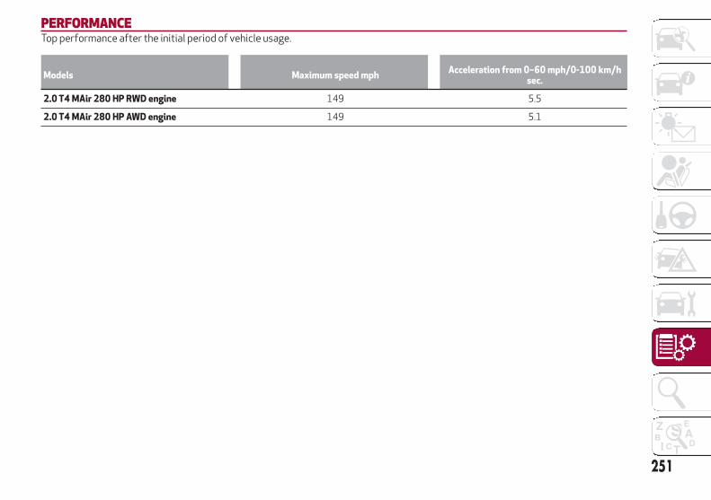
PERFORMANCETop performance after the initial period of vehicle usage.
Models Maximum speed mphAcceleration from 0–60 mph/0-100 km/h
sec.
2.0 T4 MAir 280 HP RWD engine 149 5.5
2.0 T4 MAir 280 HP AWD engine 149 5.1
251

252
This page is intentionally left blank
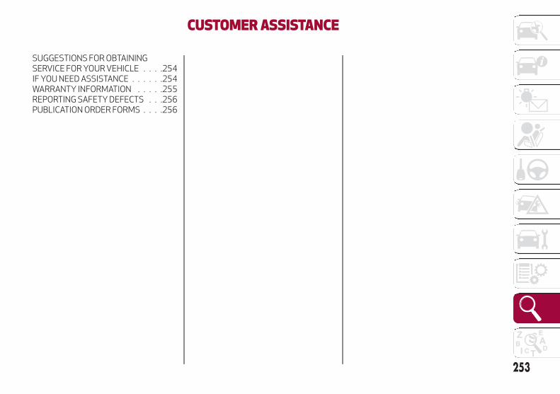
CUSTOMER ASSISTANCE
SUGGESTIONS FOR OBTAININGSERVICE FOR YOUR VEHICLE . . . .254IF YOU NEED ASSISTANCE . . . . . .254WARRANTY INFORMATION . . . . .255REPORTING SAFETY DEFECTS . . .256PUBLICATION ORDER FORMS . . . .256
253
SUGGESTIONS FOR OBTAININGSERVICE FOR YOUR VEHICLEPrepare For The AppointmentIf you are having warranty work done, besure to bring the right papers with you, aswell as your warranty folder. All work tobe performed may not be covered by thewarranty. Discuss additional charges withthe service manager. Keep a maintenancelog of your vehicle's service history, asthis can often provide a clue to thecurrent problem.
Prepare A ListMake a written list of your vehicle'sproblems or the specific work you wantdone. If you've had an accident or workdone that is not on your maintenance log,let the service advisor know.
Be Reasonable With RequestsIf you list a number of items and you musthave your vehicle by the end of the day,discuss the situation with the serviceadvisor and list the items in order ofpriority. At many authorized dealers, youmay obtain a rental vehicle at a minimaldaily charge. If you need a rental, it isadvisable to make these arrangementswhen you call for an appointment.
IF YOU NEED ASSISTANCEThe manufacturer and its authorizeddealer are vitally interested in yoursatisfaction. We want you to be happywith our products and services.Warranty service must be done by anauthorized dealer. We stronglyrecommend that you take the vehicle toan authorized dealer. They know yourvehicle the best, and are most concernedthat you get prompt and high qualityservice. The manufacturer's authorizeddealer have the facilities, factory-trainedtechnicians, special tools, and the latestinformation to ensure the vehicle is fixedcorrectly and in a timely manner.This is why you should always talk to anauthorized dealer service manager first.Most matters can be resolved with thisprocess.
If for some reason you are still notsatisfied, talk to the general manager orowner of the authorized dealer. Theywant to know if you need assistance.
If an authorized dealer is unable toresolve the concern, you may contact themanufacturer's customer center.
Any communication to themanufacturer's customer center shouldinclude the following information:
Owner's name and address
Owner's telephone number (home andoffice)
Authorized dealer name
Vehicle Identification Number (VIN)
Vehicle delivery date and mileage
Alfa Romeo Customer CenterP.O. Box 21–8004Auburn Hills, MI 48321–8004Phone: 1-844-Alfa-USA(1-844-253-2872)
Alfa Romeo Customer Center (Canada)P.O. Box 1621Windsor, Ontario N9A 4H6Phone: 1-800-465-2001 (English)Phone: 1-800-387-9983 (French)
Customer Assistance For The HearingOr Speech Impaired (TDD/TTY)To assist customers who have hearingdifficulties, the manufacturer hasinstalled special TDD(Telecommunication Devices for theDeaf) equipment at its customer center.Any hearing or speech impairedcustomer, who has access to a TDD or aconventional teletypewriter (TTY) in theUnited States, can communicate with themanufacturer by dialing1-800-380-CHRY.Canadian residents with hearingdifficulties that require assistance canuse the special needs relay serviceoffered by Bell Canada. For TTYteletypewriter users, dial 711 and for
254
CU
STO
ME
RA
SS
ISTA
NC
E

Voice callers, dial 1-800-855-0511 toconnect with a Bell Relay Serviceoperator.
Service ContractYou may have purchased a servicecontract for a vehicle to help protect youfrom the high cost of unexpected repairsafter the manufacturer's New VehicleLimited Warranty expires. Themanufacturer stands behind only themanufacturer's service contracts. If youpurchased a manufacturer's servicecontract, you will receive Plan Provisionsand an Owner Identification Card in themail within three weeks of the vehicledelivery date. If you have any questionsabout the service contract, call themanufacturer's Service ContractNational Customer Hotline at1-800-521-9922 (Canadian residents,call (800) 465-2001 English / (800)387-9983 French).The manufacturer will not stand behindany service contract that is not themanufacturer's service contract. It is notresponsible for any service contractother than the manufacturer's servicecontract. If you purchased a servicecontract that is not a manufacturer'sservice contract, and you require serviceafter the manufacturer's New VehicleLimited Warranty expires, please refer tothe contract documents, and contact theperson listed in those documents.
We appreciate that you have made amajor investment when you purchasedthe vehicle. An authorized dealer has alsomade a major investment in facilities,tools, and training to assure that you areabsolutely delighted with the ownershipexperience. You will be pleased with theirsincere efforts to resolve any warrantyissues or related concerns.
Warning!
Engine exhaust (internal combustion enginesonly), some of its constituents, and certainvehicle components contain, or emit,chemicals known to the State of Californiato cause cancer and birth defects, or otherreproductive harm. In addition, certain fluidscontained in vehicles and certain products ofcomponent wear contain, or emit, chemicalsknown to the State of California to causecancer and birth defects, or otherreproductive harm.
WARRANTY INFORMATIONSee the Warranty Information Booklet,for the terms and provisions of FCA USLLC warranties applicable to this vehicleand market.
255

REPORTING SAFETY DEFECTSIn The 50 United States AndWashington, D.C.
If you believe that your vehicle has adefect that could cause a crash orcause injury or death, you shouldimmediately inform the NationalHighway Traffic SafetyAdministration (NHTSA) in additionto notifying FCA US LLC.
If NHTSA receives similarcomplaints, it may open aninvestigation, and if it finds that asafety defect exists in a group ofvehicles, it may order a recall andremedy campaign. However, NHTSAcannot become involved in individualproblems between you, yourauthorized dealer or FCA US LLC.
To contact NHTSA, you may call theVehicle Safety Hotline toll free at1-888-327-4236 (TTY:1-800-424-9153); or go tohttp://www.safercar.gov ; or write to:Administrator, NHTSA, 1200 New JerseyAvenue, SE., West Building, Washington,D.C. 20590. You can also obtain otherinformation about motor vehicle safetyfrom http://www.safercar.gov .
In Canada
If you believe that your vehicle has asafety defect, you should contact theCustomer Service Departmentimmediately. Canadian customerswho wish to report a safety defect tothe Canadian government shouldcontact Transport Canada, MotorVehicle Defect Investigations andRecalls at 1-800-333-0510 or go tohttp://www.tc.gc.ca/roadsafety/ .
PUBLICATION ORDER FORMSTo order the following manuals, you mayuse either the website or the phonenumbers listed below. Visa, Mastercard,American Express, and Discover ordersare accepted.Service Manuals
These comprehensive Service Manualsprovide the information that studentsand professional technicians need indiagnosing/troubleshooting, problemsolving, maintaining, servicing, andrepairing FCA US LLC vehicles. Acomplete working knowledge of thevehicle, system, and/or components iswritten in straightforward language withillustrations, diagrams, and charts.Diagnostic Procedure Manuals
Diagnostic Procedure Manuals are filledwith diagrams, charts and detailedillustrations. These practical manualsmake it easy for students and techniciansto find and fix problems oncomputer-controlled vehicle systems andfeatures. They show exactly how to findand correct problems the first time, usingstep-by-step troubleshooting anddrivability procedures, proven diagnostictests, and a complete list of all tools andequipment.
256
CU
STO
ME
RA
SS
ISTA
NC
E
Owner's Manuals
These Owner's Manuals have beenprepared with the assistance of serviceand engineering specialists to acquaintyou with specific FCA US LLC vehicles.Included are starting, operating,emergency and maintenance proceduresas well as specifications, capabilities andsafety tips.Call toll free at:
1-800-890-4038 (U.S.)
1-800-387-1143 (Canada)
OrVisit us on the Worldwide Web at:
www.techauthority.com
257

258
This page is intentionally left blank

INDEXAccessories Purchased By
The Owner . . . . . . . . . . . . . . . . .3
Active Aerodynamics . . . . . . . . . . .58
Active Safety Systems . . . . . . . . . .92
Adaptive Cruise Control. . . . . . . . .151
Adaptive Cruise Control (ACC)(Cruise Control) . . . . . . . . . . . .151
Additional Heaters . . . . . . . . . . . . .48
Additives, Fuel . . . . . . . . . . . . . .247
Air Bag . . . . . . . . . . . . . . . . . . .111
Air Bag Components . . . . . .110,115
Air Bag Operation . . . . . . . . . . .112
Air Bag Warning Light . . . . . . . .110
Driver Knee Air Bag . . . . . . . . . .113
Enhanced Accident Response . . .194
Event Data Recorder (EDR) . . . . .195
Front Air Bag . . . . . . . . . . . . .111
If A Deployment Occurs . . . . . . .115
Knee Impact Bolsters . . . . . . . .113
Maintaining Your Air BagSystem . . . . . . . . . . . . . . . . .117
Redundant Air Bag WarningLight . . . . . . . . . . . . . . . . . .111
Side Air Bags . . . . . . . . . . . . .113
Transporting Pets . . . . . . . . . .128
Air Bag Light. . . . . . . . . . . . .110,129
Air Bag Maintenance. . . . . . . . . . .117
Air Pressure, Tires . . . . . . . . . . . .221
Alarm (Security Alarm) . . . . . . . . . .19
Alfa Active Suspension (AAS) . . . . .146
Alfa DNA System . . . . . . . . . . . . .143
Anti-Lock Braking (ABS) System . . . .92
Automatic Dimming Mirror . . . . . . . .32
Automatic Headlights . . . . . . . . . . .34
Automatic Temperature Control(ATC) . . . . . . . . . . . . . . . . . . .43
Automatic Transmission . . . . . . . .138
Auxiliary Driving Systems . . . . . . . .95
B-Pillar Location . . . . . . . . . . . . .218
Battery . . . . . . . . . . . . . . . . . . .205
Battery Recharging . . . . . . . . . . .206
Belts, Seat . . . . . . . . . . . . . . . . .129
Blind Spot Monitoring . . . . . . . . . . .95
Bodywork (Cleaning AndMaintenance) . . . . . . . . . . . . .232
Brakes . . . . . . . . . . . . . . . . . . .240
Brake Fluid Level . . . . . . . . . . .205
Brightness, Interior Lights . . . . . . . .39
Bulbs, Light . . . . . . . . . . . . . . . .130
Camera, Rear . . . . . . . . . . . . . . .166
Carbon Monoxide Warning . . . . . . .128
Cargo Tie-Downs . . . . . . . . . . . . . .53
Certification Label . . . . . . . . . . . .169
Changing A Flat Tire . . . . . . . . . . .213
Chart, Tire Sizing . . . . . . . . . . . . .215
Checking Levels . . . . . . . . . . . . .203
Checking Your Vehicle For Safety . . .128
Checks, Safety . . . . . . . . . . . . . .128
Child Restraint . . . . . . . . . . . . . .118
Child RestraintsBooster Seats . . . . . . . . . . . . .121
Child Restraints . . . . . . . . . . . .118
Child Seat Installation . . . . . . . .126
How To Stow An Unused ALRSeat Belt . . . . . . . . . . . . . . . .125
Infants And Child Restraints . . . .120
LATCH Positions . . . . . . . . . . .122
Lower Anchors And Tethers ForChildren . . . . . . . . . . . . . . . .122
Older Children And ChildRestraints . . . . . . . . . . . . . . .120
Seating Positions . . . . . . . . . . .121
Using The Top Tether Anchorage . .127
Clean Air Gasoline . . . . . . . . . . . .246
CleaningWheels . . . . . . . . . . . . . . . . .226
Climate Control . . . . . . . . . . . .41,44
Close The Hood . . . . . . . . . . . . . . .52
Compact Spare Tire . . . . . . . . . . .226
Contract, Service . . . . . . . . . . . . .255
Courtesy Mirror Light (BulbReplacement) . . . . . . . . . . . . .177
Cruise Control (Speed Control) . . . .151
Cupholder . . . . . . . . . . . . . . . . . .58
Cupholders . . . . . . . . . . . . . . . . .58

Customer Assistance . . . . . . . . . .254
Daytime Running Lights. . . . . . . . . .34
Daytime Running Lights (DRL) . . . . . .34
Defroster, Windshield . . . . . . . . . .129
Dimensions . . . . . . . . . . . . . . . .243
Direction Indicators (Changing ABulb). . . . . . . . . . . . . . . . . . .177
Disabled Vehicle Towing. . . . . . . . .192
Door LocksChild-Protection Door Lock —Rear Doors . . . . . . . . . . . . . . . .24
Power Door Locks . . . . . . . . . . .24
Doors. . . . . . . . . . . . . . . . . . . . .20
Drive Train Control (DTC) System . . . .92
Driving Modes . . . . . . . . . . . . . .144
Dynamic Steering Torque (DST)System . . . . . . . . . . . . . . . . . .94
Electric Park Brake. . . . . . . . . . . .135
Electric Remote Mirrors . . . . . . . . .32
Electric Steering Wheel Heating. . . . .32
Electronic Speed Control . . . . . . . .149
Electronic Speed Control(Cruise Control) . . . . . .149,150,151
Electronic Stability Control (ESC)System . . . . . . . . . . . . . . . . . .93
Emergency Refuelling . . . . . . . . . .191
Emergency Starting . . . . . . . . . . .188
Emergency, In Case Of. . . . . . . . . .185
Hazard Warning Flasher . . . . . . .174
Jacking . . . . . . . . . . . . . . . . .213
Jump Starting . . . . . . . . . .188,189
Overheating . . . . . . . . . . . . . .191
Tow Hooks . . . . . . . . . . . . . . .193
Towing . . . . . . . . . . . . . . . . .192
Engine . . . . . . . . . . . . . . . . . . .237
Block Heater . . . . . . . . . . . . . .135
Engine Coolant Level . . . . . . . . .204
Exhaust Gas Caution . . . . . . . . .128
Fuel Requirements . . . . . . . . . .246
Jump Starting . . . . . . . . . .188,189
Overheating . . . . . . . . . . . . . .191
Starting . . . . . . . . . . . . . . . .190
Temperature Gauge . . . . . . . . . .61
Engine Compartment . . . . . . . . . .203
Engine Compartment (Washing) . . . .233
Engine OilLevel Check . . . . . . . . . . . . . .204
Engine Overheating . . . . . . . . . . .191
Enhanced Accident ResponseFeature . . . . . . . . . . . . . . . . .194
Environmental Protection Systems. . .58
Ethanol . . . . . . . . . . . . . . . . . . .246
Exhaust Gas Caution. . . . . . . . . . .128
Exhaust System . . . . . . . . . . . . .128
Exterior Lighting . . . . . . . . . . . .34,35
Exterior Lights . . . . . . . . . . . .34,130
External Lights . . . . . . . . . . . . . . .34
FlashersHazard Warning . . . . . . . . . . . .174
Turn Signal . . . . . . . . . . . .36,130
Fluid Leaks . . . . . . . . . . . . . . . .130
Fluids And Lubricants . . . . . . . . . .249
Forward Collision Warning . . . . . . . .97
Front Light Cluster With Main BeamXenon Gas Discharge Headlights(Bulb Replacement). . . . . . . . . .177
Front Mobile Spoiler (Alfa ActiveAero) . . . . . . . . . . . . . . . . . . .58
Front Seat Electric Heating . . . . . . .27
Front Seats (Power Seats) . . . . . . . .26
Front WipersWiper Operation . . . . . . . . . . . .39
FuelAdditives . . . . . . . . . . . . . . .247
Clean Air . . . . . . . . . . . . . . . .246
Ethanol . . . . . . . . . . . . . . . . .246
Gauge . . . . . . . . . . . . . . . . . .61
Materials Added . . . . . . . . . . .247
Methanol . . . . . . . . . . . . . . .246
Fuse Boxes . . . . . . . . . . . . . . . .180
Fuses (Replacement) . . . . . . . . . .179
Garage Door Opener (HomeLink) . . . .55
Gasoline, Clean Air . . . . . . . . . . . .246
Gasoline, Reformulated . . . . . . . . .246
GaugesSpeedometer . . . . . . . . . . . . . .61
IND
EX

Tachometer . . . . . . . . . . . . . . .61
General Information . . . . . . . . .97,158
Glove Compartment . . . . . . . . . . . .54
Glove Compartment Light . . . . . . . .37
Glove Compartment Light(Bulb Replacement). . . . . . . . . .178
GVWR . . . . . . . . . . . . . . . . . . .169
Hazard Warning Flasher . . . . . . . . .174
Head Restraints . . . . . . . . . . . . . .30
Head Rests . . . . . . . . . . . . . . . . .30
HeadlightsSwitch . . . . . . . . . . . . . . . .34,35
Headlights (Cleaning) . . . . . . . . . .233
Heated Mirrors . . . . . . . . . . . . . . .33
Heater, Engine Block. . . . . . . . . . .135
High Beam Headlights . . . . . . . . . . .35
Automatic High Beam Headlights. . . . . . . . . . . . . . . . . . . . . . .35
Hill Start Assist (HSA) System. . . . . .94
Hood . . . . . . . . . . . . . . . . . . . . .51
Hood Release . . . . . . . . . . . . . . . .51
Identification Data . . . . . . . . . . . .236
Ignition . . . . . . . . . . . . . . . . . . . .16
Installing Electrical/ElectronicDevices . . . . . . . . . . . . . . . . . . .3
Instrument Cluster DisplayInstrument Cluster Display . . . . . .62
Reconfigurable InstrumentCluster Display . . . . . . . . . . . . .62
Instrument Panel FeaturesInstrument Panel Features . . . . . .60
Interior Ambient Lighting . . . . . . . . .37
Interior Lights. . . . . . . . . . . . . . . .36
Interiors (Cleaning). . . . . . . . . . . .233
Internal Equipment . . . . . . . . . . . .54
Jack Operation . . . . . . . . . . . . . .213
Jump Starting . . . . . . . . . . . .188,189
Key FobRemote Keyless Entry . . . . . . . . .14
Keyless Entry System/ImmobilizerSystem . . . . . . . . . . . . . . . . . .18
Lane Change . . . . . . . . . . . . . . . .36
Lane Change And Turn Signals . . . . . .36
Lane Departure Warning System . . .163
LaneSense. . . . . . . . . . . . . . . . .163
Lap/Shoulder Belts . . . . . . . . . . .105
Latches. . . . . . . . . . . . . . . . . . .130
Leaks, Fluid . . . . . . . . . . . . . . . .130
Life Of Tires . . . . . . . . . . . . . . . .224
Lifting The Vehicle . . . . . . . . . . . .213
Light Bulbs. . . . . . . . . . . . . . . . .130
Types Of Bulbs . . . . . . . . . . . .175
Light Switch. . . . . . . . . . . . . . . . .34
Lights. . . . . . . . . . . . . . . . . . . .130
Air Bag . . . . . . . . . . . . . .110,129
Automatic Headlights . . . . . . . . .34
Courtesy/Reading . . . . . . .36,37,38
Daytime Running . . . . . . . . . . . .34
Exterior . . . . . . . . . . . . . . . .130
Hazard Warning Flasher . . . . . . .174
Headlight Switch . . . . . . . . . .34,35
Headlights . . . . . . . . . . . . .34,35
High Beam . . . . . . . . . . . . . . . .35
Instrument Cluster . . . . . . . .34,35
Intensity Control . . . . . . . . . . . .39
Interior . . . . . . . . . . . . . . . .37,38
Map Reading . . . . . . . . . . . . . .36
Park . . . . . . . . . . . . . . . . . . .34
Reading . . . . . . . . . . . . . . . . .36
Turn Signal . . . . . . . . . . . .36,130
Loading Vehicle . . . . . . . . . . . . . .169
Tires . . . . . . . . . . . . . . . . . .218
Luggage Compartment Light(Bulb Replacement). . . . . . . . . .178
Luggage/Cargo Capacity . . . . . . . . .52
Manual, Service . . . . . . . . . . . . . .256
Methanol. . . . . . . . . . . . . . . . . .246
MirrorsAutomatic Dimming . . . . . . . . . .32
Electric Powered . . . . . . . . . . . .32
Electric Remote . . . . . . . . . . . .32
Heated . . . . . . . . . . . . . . . . . .33
OBD System . . . . . . . . . . . . . . . .89

Occupant Restraints . . . . . . . . . . .104
Overheating, Engine . . . . . . . . . . .191
Owner's Manual (Operator Manual) . .256
Paintwork (Cleaning AndMaintenance) . . . . . . . . . . . . .232
Panic Brake Assist (PBA) System . . . .93
Park Sensors System . . . . . . . . . .158
Passive Entry (System) . . . . . . . . . .21
Performance (Top Speed) . . . . . . . .251
Pets . . . . . . . . . . . . . . . . . . . . .128
Placard, Tire And LoadingInformation . . . . . . . . . . . . . .218
PowerMirrors . . . . . . . . . . . . . . . . . .32
Seats . . . . . . . . . . . . . . . . . . .26
Sunroof . . . . . . . . . . . . . . . . .50
Power Sunroof . . . . . . . . . . . . . . .50
Power Supply . . . . . . . . . . . . . . .238
Power Windows . . . . . . . . . . . . . .48
Pregnant Women And Seat Belts . . .108
PretensionersSeat Belts . . . . . . . . . . . . . . .108
Prolonged Vehicle Inactivity . . . . . .231
Radial Ply Tires . . . . . . . . . . . . . .223
Radio FrequencyGeneral Information . . . . . .16,18,24
Radio Transmitters And MobilePhones . . . . . . . . . . . . . . . . . . .4
Rear Camera . . . . . . . . . . . . . . .166
Rear Cross Path . . . . . . . . . . . . . .95
Rear Seats. . . . . . . . . . . . . . . . . .28
Rear View Mirrors . . . . . . . . . . . . .32
Reformulated Gasoline . . . . . . . . .246
Refueling Procedure . . . . . . . . . . .168
Refueling The Vehicle . . . . . . . . . .168
Refuelling . . . . . . . . . . . . . . . . .248
Reminder, Seat Belt . . . . . . . . . . .105
Remote Starting System . . . . . . . .132
Replacement Tires . . . . . . . . . . . .225
Replacing A Bulb . . . . . . . . . . . . .174
Replacing An External Bulb . . . . . . .177
Replacing An Internal Bulb . . . . . . .177
Reporting Safety Defects . . . . . . .256
Restraint, Head . . . . . . . . . . . . . . .30
Restraints, Child . . . . . . . . . . . . .118
Rims And Tires . . . . . . . . . . . . . .213
Safety Checks Inside Vehicle . . . . . .129
Safety Checks Outside Vehicle. . . . .130
Safety Defects, Reporting . . . . . . .256
Safety Information, Tire. . . . . . . . .213
Safety Tips . . . . . . . . . . . . . . . .128
Safety, Exhaust Gas . . . . . . . . . . .128
Saving Fuel . . . . . . . . . . . . . . . .171
SBL Function . . . . . . . . . . . . . . . .36
Scheduled Servicing . . . . . . . . . . .198
Scheduled Servicing Program(2.0 T4 MAir Engine Versions) . . .200
Seat BeltEnergy Management Feature . . . .109
Lap/Shoulder Belt Untwisting . . .107
Lap/Shoulder Belts . . . . . . . . . .105
Pregnant Women . . . . . . . . . . .108
Seat Belt Pretensioner . . . . . . .108
Seat Belt Reminder . . . . . . . . . .105
Seat Belt Reminder . . . . . . . . . . .105
Seat Belts . . . . . . . . . . . . . .104,129
Child Restraint . . . . . . . . . . . .118
Front Seat . . . . . . . . . . . .104,105
Inspection . . . . . . . . . . . . . . .129
Pregnant Women . . . . . . . . . . .108
Pretensioners . . . . . . . . . . . . .108
Rear Seat . . . . . . . . . . . . . . .105
Untwisting Procedure . . . . . . . .107
Seats . . . . . . . . . . . . . . . . . . . . .25
Adjustment . . . . . . . . . . . . . . .25
Head Restraints . . . . . . . . . . . .30
Height Adjustment . . . . . . . . . . .26
Power . . . . . . . . . . . . . . . . . .26
Tilting . . . . . . . . . . . . . . . . . .26
Service Assistance . . . . . . . . . . . .254
Service Contract . . . . . . . . . . . . .255
Service Manuals . . . . . . . . . . . . .256
Servicing Procedures . . . . . . . . . .207
IND
EX

Shoulder Belts . . . . . . . . . . . . . .105
Signals, Turn. . . . . . . . . . . . . .36,130
Snow Chains. . . . . . . . . . . . . . . .228
Snow Tires . . . . . . . . . . . . . . . . .228
Spare Tire . . . . . . . . . . . . . .225,226
Speed ControlAccel/Decel . . . . . . . . . . . . . .150
Cancel . . . . . . . . . . . . . . . . .151
Resume . . . . . . . . . . . . . . . .151
Set . . . . . . . . . . . . . . . . . . .150
Speed Control(Cruise Control) . . . . . . . . .150,151
Speed Limiter . . . . . . . . . . . . . . .148
Split Folding Rear Seat . . . . . . . . . .28
Starting . . . . . . . . . . . . . . . . . .190
Cold Weather . . . . . . . . . . . . .133
Starting And Operating . . . . . . . . .190
Starting Procedures . . . . . . . . . . .190
Starting The Engine . . . . . . . . . . .132
SteeringTilt Column . . . . . . . . . . . . . . .31
Wheel, Heated . . . . . . . . . . . . .32
Wheel, Tilt . . . . . . . . . . . . . . . .31
Steering System . . . . . . . . . . . . .242
Steering Wheel . . . . . . . . . . . . . . .31
Stop/Start System. . . . . . . . . . . .146
Storage . . . . . . . . . . . . . . . . . . .57
Suggestions For Driving. . . . . . . . .171
Sun Roof . . . . . . . . . . . . . . . . . . .50
Sun Visors . . . . . . . . . . . . . . . . . .54
Supplemental Restraint System -Air Bag . . . . . . . . . . . . . . . . .111
Suspension . . . . . . . . . . . . . . . .241
Symbols . . . . . . . . . . . . . . . . . . . .6
Telescoping Steering Column . . . . . .31
Tie Down Hooks, Cargo . . . . . . . . . .53
Tilt Steering Column . . . . . . . . . . . .31
Tire And Loading InformationPlacard . . . . . . . . . . . . . . . . .218
Tire Markings . . . . . . . . . . . . . . .213
Tire Safety Information . . . . . . . . .213
Tire Service Kit . . . . . . . . . . . . . .185
Tires . . . . . . . . . . .130,221,225,230
Aging (Life Of Tires) . . . . . . . . .224
Air Pressure . . . . . . . . . . . . . .221
Changing . . . . . . . . . . . . . . . .213
Compact Spare . . . . . . . . . . . .226
Flat Changing . . . . . . . . . . . . .185
General Information . . . . . .221,225
High Speed . . . . . . . . . . . . . .222
Inflation Pressures . . . . . . . . . .221
Jacking . . . . . . . . . . . . . . . . .213
Life Of Tires . . . . . . . . . . . . . .224
Load Capacity . . . . . . . . . . . . .218
Quality Grading . . . . . . . . . . . .230
Radial . . . . . . . . . . . . . . . . . .223
Replacement . . . . . . . . . . . . .225
Safety . . . . . . . . . . . . . .213,221
Sizes . . . . . . . . . . . . . . . . . .215
Snow Tires . . . . . . . . . . . . . . .228
Spare Tire . . . . . . . . . . . .225,226
Spinning . . . . . . . . . . . . . . . .224
Tread Wear Indicators . . . . . . . .224
To Open Hood . . . . . . . . . . . . . . . .51
Tow Hooks, Emergency . . . . . . . . .193
TowingDisabled Vehicle . . . . . . . . . . .192
Towing Trailers . . . . . . . . . . . . . .170
TPMS (Tire Pressure MonitoringSystem). . . . . . . . . . . . . . . . .101
Traction Control System (TCS). . . . . .93
Transmission . . . . . . . . . . . . . . .239
Transporting Animals . . . . . . . . . .172
Transporting Passengers . . . . . . . .172
Transporting Pets . . . . . . . . . . . .128
Tread Wear Indicators . . . . . . . . . .224
Turn Signals . . . . . . . . . . . . . . . . .36
Uniform Tire Quality Grades . . . . . .230
Untwisting Procedure, Seat Belt. . . .107
Use Of The Owner’s Manual . . . . . . . .5

Vehicle Changes/Alterations . . . . . . .3
Vehicle Identification Number . . . . .236
Vehicle Loading . . . . . . . . . . .169,218
Vent Operation . . . . . . . . . . . . . . .41
Warning Flasher, Hazard . . . . . . . .174
Warranty Information . . . . . . . . . .255
Washer Fluid ForWindshield/Headlights. . . . . . . .205
Washers, Windshield. . . . . . . . . . . .39
Weights . . . . . . . . . . . . . . . . . .245
Wheel And Wheel Trim. . . . . . . . . .226
Wheel And Wheel Trim Care . . . . . .226
Wheels And Tires . . . . . . . . . . . . .213
Windows (Cleaning) . . . . . . . . . . .233
Windshield Defroster . . . . . . . . . .129
Windshield Wiper . . . . . . . . . . . . .39
Replacing Blades . . . . . . . . . . .209
Windshield Wiper/WasherSmart Washing Function . . . . . . .40
Windshield Wipers . . . . . . . . . . . . .39
Wrecker Towing. . . . . . . . . . . . . .192
IND
EX

INSTALLATION OF RADIO TRANSMITTINGEQUIPMENTSpecial design considerations are incorporated into thisvehicle’s electronic system to provide immunity to radiofrequency signals. Mobile two-way radios and telephoneequipment must be installed properly by trained person-nel. The following must be observed during installation.
The positive power connection should be made directlyto the battery and fused as close to the battery as possible.The negative power connection should be made to bodysheet metal adjacent to the negative battery connection.This connection should not be fused.
Antennas for two-way radios should be mounted on theroof or the rear area of the vehicle. Care should be usedin mounting antennas with magnet bases. Magnets mayaffect the accuracy or operation of the compass onvehicles so equipped.
The antenna cable should be as short as practical androuted away from the vehicle wiring when possible. Useonly fully shielded coaxial cable.
Carefully match the antenna and cable to the radio toensure a low Standing Wave Ratio (SWR).
Mobile radio equipment with output power greater thannormal may require special precautions.
All installations should be checked for possible interfer-ence between the communications equipment and thevehicle’s electronic systems.
VEHICLES SOLD IN CANADAWith respect to any Vehicles Sold in Canada, the name FCAUS LLC shall be deemed to be deleted and the name FCACanada Inc. used in substitution therefore.
DRIVING AND ALCOHOLDrunken driving is one of the most frequent causes ofaccidents.Your driving ability can be seriously impaired with bloodalcohol levels far below the legal minimum. If you aredrinking, don’t drive. Ride with a designated non-drinking driver, call a cab, a friend, or use public trans-portation.
WARNING!
Driving after drinking can lead to an accident.Your perceptions are less sharp, your reflexes areslower, and your judgment is impaired when youhave been drinking. Never drink and then drive.
This manual illustrates and describes the operation offeatures and equipment that are either standard or op-tional on this vehicle. This manual may also include adescription of features and equipment that are no longeravailable or were not ordered on this vehicle. Pleasedisregard any features and equipment described in thismanual that are not on this vehicle.
FCA US LLC reserves the right to make changes in designand specifications, and/or make additions to or improve-ments to its products without imposing any obligationupon itself to install them on products previously manu-factured.
Copyright © 2016 FCA US LLC
2 0 1 7
20
17
GIU
LIA
GIULIAThird Edition
Printed in U.S.A.
©2017 FCA US LLC. All Rights Reserved.ALFA ROMEO is a registered trademark ofFCA Group Marketing S.p.A., used with permission.
OW N E R ’ S M A N U A L17GABASE-126-AC


