research papers 710 https://doi.org/10.1107/S2059798317011597 Acta Cryst. (2017). D73, 710–728 Received 16 June 2017 Accepted 7 August 2017 Edited by M. Czjzek, Station Biologique de Roscoff, France Keywords: small-angle scattering; SAXS; SANS; biomolecular structure; proteins; DNA; RNA; structural modelling; hybrid structural modelling; publication guidelines; integrative structural biology. Supporting information: this article has supporting information at journals.iucr.org/d 2017 publication guidelines for structural modelling of small-angle scattering data from biomolecules in solution: an update Jill Trewhella, a * Anthony P. Duff, b Dominique Durand, c Frank Gabel, d J. Mitchell Guss, a Wayne A. Hendrickson, e Greg L. Hura, f David A. Jacques, g Nigel M. Kirby, h Ann H. Kwan, a Javier Pe ´rez, i Lois Pollack, j Timothy M. Ryan, h Andrej Sali, k Dina Schneidman-Duhovny, l Torsten Schwede, m Dmitri I. Svergun, n Masaaki Sugiyama, o John A. Tainer, p Patrice Vachette, c John Westbrook q and Andrew E. Whitten b a School of Life and Environmental Sciences, The University of Sydney, NSW 2006, Australia, b ANSTO, New Illawarra Road, Lucas Heights, NSW 2234, Australia, c Institut de Biologie Inte ´grative de la Cellule, UMR 9198, Ba ˆtiment 430, Universite ´ Paris-Sud, 91405 Orsay CEDEX, France, d Universite ´ Grenoble Alpes, Commissariat a ` l’Energie Atomique (CEA), Centre National de la Recherche Scientifique (CNRS), Institut de Biologie Structurale (IBS), and Institut Laue– Langevin, 71 Avenue des Martyrs, 38000 Grenoble, France, e Department of Biochemistry and Molecular Biophysics, Columbia University, New York, NY 10032, USA, f Molecular Biophysics and Integrated Bioimaging, Lawrence Berkeley National Laboratory, Berkeley, CA 94720, USA, g University of Technology Sydney, ithree Institute, 15 Broadway, Ultimo, NSW 2007, Australia, h Australian Synchrotron, 800 Blackburn Road, Clayton, VIC 3168, Australia, i Synchrotron SOLEIL, L’Orme des Merisiers, Saint-Aubin BP48, 91192 Gif-sur-Yvette CEDEX, France, j School of Applied and Engineering Physics, Cornell University, Ithaca, NY 14853-2501, USA, k Department of Bioengineering and Therapeutic Sciences, Department of Pharmaceutical Chemistry, and California Institute for Quantitative Biosciences (QB3), University of California San Francisco, San Francisco, California, USA, l School of Computer Science and Engineering, Institute of Life Sciences, The Hebrew University of Jerusalem, Jerusalem 9190401, Israel, m Biozentrum, University of Basel and SIB Swiss Institute of Bioinformatics, Basel, Switzerland, n European Molecular Biology Laboratory (EMBL) Hamburg, c/o DESY, Nokestrasse 85, 22607 Hamburg, Germany, o Research Reactor Institute, Kyoto University, Kumatori, Sennan-gun, Osaka 590-0494, Japan, p Basic Science Research Division, Molecular and Cellular Oncology, MD Anderson Cancer Center, University of Texas, Houston, Texas, USA, and q Department of Chemistry and Chemical Biology, Rutgers University, New Brunswick, NJ 07102, USA. *Correspondence e-mail: [email protected]In 2012, preliminary guidelines were published addressing sample quality, data acquisition and reduction, presentation of scattering data and validation, and modelling for biomolecular small-angle scattering (SAS) experiments. Bio- molecular SAS has since continued to grow and authors have increasingly adopted the preliminary guidelines. In parallel, integrative/hybrid determination of biomolecular structures is a rapidly growing field that is expanding the scope of structural biology. For SAS to contribute maximally to this field, it is essential to ensure open access to the information required for evaluation of the quality of SAS samples and data, as well as the validity of SAS-based structural models. To this end, the preliminary guidelines for data presentation in a publication are reviewed and updated, and the deposition of data and associated models in a public archive is recommended. These guidelines and recommendations have been prepared in consultation with the members of the International Union of Crystallography (IUCr) Small-Angle Scattering and Journals Commissions, the Worldwide Protein Data Bank (wwPDB) Small-Angle Scattering Validation Task Force and additional experts in the field. 1. Introduction The objective of publishing the preliminary guidelines for biomolecular small-angle scattering (SAS) experiments (Jacques, Guss, Svergun et al., 2012; Jacques, Guss & Trewhella, 2012) was to provide a reporting framework so that ‘readers can independently assess the quality of the data and the basis for any interpretations presented’. The focus was on ISSN 2059-7983
directory-of-sans-instruments/). Beam size and shape also play
a key role in data smearing. Modern synchrotron beams and
most laboratory-based instruments have sufficiently small
beam dimensions (in the range of tenths of a millimetre to
millimetres at the detector) such that smearing effects can be
safely ignored for most applications. Neutron beam dimen-
sions can be as large as 100 mm at the detector and thus can
cause significant instrumental smearing. Some laboratory-
based SAXS instruments use line-focused sources to increase
the X-ray flux on the sample. These types of instruments,
which were first implemented by Otto Kratky (see chapter 3 of
Glatter & Kratky, 1982), have since been further developed
for laboratory-based SAS applications (see, for example,
Bergmann et al., 2000) and data treatments must deal with
significant instrumental smearing effects. Data ‘desmearing’
can be performed using the ratio of points in the smeared-
model and unsmeared-model I(q) profiles calculated using
Fourier and/or linear regularization techniques, such as the
indirect Fourier transform of a P(r) model if the particle
maximum dimension (dmax) is well determined. Alternatively,
iterative methods can be used, although these typically
amplify statistical errors (see Vad & Sager, 2011 and refer-
ences therein). However, the preferred approach is to smear
the model I(q) profile analytically using the measured beam
profile for direct comparison with experimental data.
During data reduction, the SAS intensity data also should
be placed on an absolute scale in units of cm�1 by comparison
with the incident beam flux or the scattering from pure H2O
(Orthaber et al., 2000; Jacrot & Zaccai, 1981). Pure H2O is a
readily accessible, universal standard whose scattering has
been well characterized over a wide range of temperatures.
Secondary standards are also available, such as glassy carbon
(see the new NIST Standard Reference Material 3600; https://
www-s.nist.gov/srmors/view_detail.cfm?srm=3600; Allen et al.,
2017). Absolute scaling enables the direct comparison of SAS
data from different instruments, including X-ray and neutron
sources, without arbitrary scaling and also enables the deter-
mination of M or V from I(0) without reference to the scat-
tering from a reference protein. In the case of SANS, it has
been routine to place the data on an absolute scale. The more
common practice for SAXS experimenters has been to
provide data on an arbitrary relative scale, which we do not
recommend for reasons that will be addressed further below.
Owing to the tremendous variety of SAS instrumentation,
the typical SAS user will need beamline scientists or instru-
ment manufacturers to provide many of the instrument and
data-acquisition parameters and references that we recom-
mend to be reported regarding data acquisition and reduction
(a summary is given in Table 2). We therefore encourage
instrument scientists to collect and provide these parameters
and references to users in an easy-to-access form at the time of
data collection.
2.3. Data presentation, analysis and validation
In order for a reader to be able to assess the quality of SAS
data and their suitability for structural modelling, it is neces-
sary that the data be presented in a clear, well described
manner along with the parameters and analyses that support
the conclusion that the SAS profile represents the shape of the
particle of interest or, in the case of flexible systems, the
population-weighted average SAS profile for the ensemble of
conformations present.
research papers
Acta Cryst. (2017). D73, 710–728 Trewhella et al. � 2017 publication guidelines for solution SAS data 713
Table 1Summary of guidelines for sample details.
Source of samples, including sample-purification protocol, a measure of thefinal purity and how it was determined.
Composition of the sample, including protein or nucleic acid sequences asmeasured, or FASTA IDs with the relevant ranges specified, plus fusiontags, ligands, cofactors, glycosylation or other modifications and thepredicted molecular mass.
Solvent/buffer pH and composition, including additives such as free-radicalscavengers used to minimize the effects of radiation damage during SAXSdata acquisition, and a statement of how the SAS-measured solvent blankwas obtained (e.g. last-step dialysate, concentrator or column flowthrough).
Sample concentration(s) and method(s) of determination, including extinctioncoefficients and wavelengths when UV absorbance measurements are used.
In the case of combined SEC–SAS experiments, a description (or reference) tothe system, column size/type/resin, injection sample concentration andvolume and flow rate.
In the case of SANS contrast-variation experiments, the deuteration level ofeach biomolecular component (e.g. from mass spectrometry) and of thesolvent (e.g. from densitometry or transmissions).
Any SAS-independent assessments of monodispersity over a range ofconditions (e.g. analytical ultracentrifugation, dynamic light scattering and/or aggregate-free gel filtration and/or multi-angle laser light scattering) thatcomplement the SAS-based assessments.
Because I(q) decreases by several orders of magnitude over
the measured q range, data should be presented as log I(q)
versus q and/or log I(q) versus log q. The former provides a
clear representation of the data over the entire q range, while
the latter will have a near-zero slope at low q if the minimum
measured q value meets the requirement of being sufficiently
small to ensure adequate characterization of the largest
particles present. A linear Guinier plot [ln I(q) versus q2;
Guinier, 1939] is a necessary but not sufficient demonstration
that a solution contains monodisperse particles of the same
size. The upper limit of the q range for the linear Guinier
approximation varies depending on the particle shape and
homogeneity. For a sphere of uniform scattering density,
Guinier showed that the limit is qRg < 1.3, while for extended
shapes and/or inhomogeneous particles this limit can be <1.0
(Feigin & Svergun, 1987). Assessment of the appropriate
Guinier limit will be aided by complementary analyses for
particle shape, such as P(r) (see below). The lower q limit for
the Guinier analysis should be the lowest, reliably measured
q value. For a particle with maximum dimensions dmax, the
minimum q value measured should be at most ��/dmax for
accurate assessment of the particle size and shape (Moore,
1980), and as a general principle it is important to measure
below this limit to have an assurance that there are no larger
particles present. It has been common practice to truncate
data at low q when there are small amounts of large M
impurities, aggregation or polydispersity present resulting in
some upturn of the Guinier plot. This practice is not to be
encouraged, but in the event that it is performed it must be
reported and justified. Truncating the most obviously affected
lower q data in the Guinier plot will not completely eliminate
the effects of the contaminant and will thus have an effect on
the derived structural parameters that must be acknowledged
and quantified to the extent possible [for example, by indi-
cating the impacts on I(0) and Rg]. The best practice would be
to also display the truncated data points, for example as empty
symbols, with filled symbols representing data points included
in the linear fit so that the reader can fully appreciate the
potential effect of truncation. For Guinier fits, a quality-of-fit
parameter such as the Pearson residual (R) or coefficient of
correlation (R2) for a linear fit is widely understood and thus is
most useful to report.
The Fourier transform of the scattering profile yields P(r)
versus r, the scattering contrast-weighted distribution of
distances r between atoms, and is generally computed as the
indirect Fourier transform of I(q) (Glatter, 1977). By its
definition, P(r) is equal to zero for r values exceeding the
maximum particle size dmax. Agreement between the P(r) and
Guinier-determined Rg and I(0) values is a good measure of
the self-consistency of the SAS profile, as P(r) is calculated
using a larger portion of the measured q range. This said, it is
not correct to simply choose a dmax that provides a solution
that agrees with the Guinier Rg. Rather, the P(r) solution must
be independently optimized with the understanding that dmax
is an input parameter to the indirect transform selected by the
user based on the observed fit of the regularized I(q) corre-
sponding to a given P(r) and how P(r) approaches zero at r = 0
and dmax. The dmax value as independently assessed from the
P(r) transform should be consistent with, but not guided by,
the known dimensions of the system from complementary
techniques. There is an inherent uncertainty in dmax that is
difficult to quantify in a rigorous and consistent way.
Furthermore, automated routines for calculating P(r) can
provide mathematically optimized solutions that are quite
unphysical, leading to erroneous dmax selection, and hence
need to be treated with great caution. The stability of the P(r)
fit needs to be carefully assessed by examining a range of dmax
values and the effects of choosing different q ranges. The
indirect Fourier transform methods for calculating P(r)
include a smoothing parameter that is a complicating factor in
assessing the quality of the fit for a given solution. A simple �2
test is straightforward to calculate, although it does have
limitations, as will be discussed below (x2.4). Another
approach used by the popular program GNOM for calculating
P(r) is to use a quality-of-fit assessment (referred to as the
‘total estimate’ ) that is based on �2 combined with a number
of ‘perceptual criteria’ (Svergun, 1992).
The molecular mass M in daltons for a scattering particle is
readily calculated as
M ¼Ið0ÞNA
Cð��MÞ2 ; ð1Þ
where I(0) is on an absolute scale in units of cm�1, NA is
Avogadro’s number, C is the concentration of the scattering
particle in g ml�1 and ��M is the scattering mass contrast,
which can be calculated as �� �, where �� is the average
research papers
714 Trewhella et al. � 2017 publication guidelines for solution SAS data Acta Cryst. (2017). D73, 710–728
Table 2Summary of guidelines for data acquisition and reduction.
Instrument type (e.g. manufacturer and model designation or beamline)specifying the source (sealed tube, rotating anode, metal jet, synchrotron,spallation neutron source or reactor) and the configuration used (point orline source, collimation details, detector details). In the case of SANS theremay be several configurations (e.g. multiple detector positions, number ofguides, apertures etc.) for a single experiment.
Beam dimensions and wavelength resolution (��/�) with data-smearingparameters where appropriate, and measured q range including qmin limitowing to instrument resolution and beam-stop size.
References to documentation for detector type and characteristics includingpixel size, the basis for error estimates and propagation (e.g. Poissoncounting statistics) and the confidence interval represented by the errors,methods for detector sensitivity and linearity corrections.
Number of sample exposures and exposure times, the normalization method(e.g. time or beam monitor counts), the method used to determine sampletransmission and how radiation damage was monitored (in the case ofSAXS).
In the case of SANS contrast-variation experiments, sample and buffertransmissions referenced to transmissions of pure 1H2O and 2H2O, fromwhich deuteration of the solvent can be checked.
Details of the sample environment, including measurement temperature,measurement cell type and path lengths, any special parameters controlled,e.g. pressure, and additional inline purification or characterizationcapabilities as appropriate.
In the case of SEC–SAS experiments, description of (or reference to) system.Standards measured and controls and method for placing SAS data on an
absolute scale in cm�1, e.g. by reference to a well characterized standardsuch as H2O or glassy carbon or the incident beam flux. As appropriate, anystandard protein measurement used as an overall check of the experimentalsetup.
Data-reduction protocol and software used, including version number.
scattering-length density difference between the particle and
its solvent in cm�2 (or cm cm�3, scattering length/unit volume)
and � is its partial specific volume in cm3 g�1 (Orthaber et al.,
2000). �� and � are both related to the molecular volume and
can be readily estimated for X-rays and neutrons from the
chemical and isotopic composition of the particle and its
solvent. For X-rays, ��M is sometimes calculated as
ð�p � �s�Þr0, where �p is the number of electrons per mass of
dry volume, �s is the electron density of the solvent and r0 is
the scattering length of an electron in cm (2.8179 � 10�13 cm;
Mylonas & Svergun, 2007). There are several web-based tools
for the calculation of these parameters from the chemical and
isotopic composition. Values for �� and � from the chemical
composition of solvent and solute for SAXS and SANS can
be obtained using the Contrast model of MULCh (http://
smb-research.smb.usyd.edu.au/NCVWeb/index.jsp); the web
version of US-SOMO (https://somo.chem.utk.edu/somo/) will
calculate � and other molecular properties from the sequence.
A biomolecular scattering-length density (�) calculator for
proteins and polynucleotides with different levels of
deuteration is also available at http://psldc.isis.rl.ac.uk/Psldc/.
These calculations are based on the volumes of the constituent
chemical groups and generally provide accurate values of � for
proteins with M > 20 kDa, where the effects of hydration and
variations in amino-acid packing have little impact on calcu-
lations. For an easy-to-use protocol for the calculation of M,
see Box 2 in Jeffries et al. (2016).
Historically, proteins have been used as a calibration stan-
dard for estimating M. From (1) it can be seen that if the
product of �� and � is assumed to be the same for all proteins,
the mass is proportional to I(0) normalized by the protein
concentration in (w/v) units (Mylonas & Svergun, 2007).
However, the simplest implementation of this ratio method
is not readily applicable to polynucleotides or protein–
polynucleotide complexes. Also, for proteins experimentally
determined values of � vary by as much as 10%. For a typical
folded and hydrated protein, � is in the range 0.70–
0.74 cm3 g�1 (Harpaz et al., 1994), and hydration, flexibility or
modifications such as glycosylation can affect the value. The
value of �� also can vary, especially in the case of bound
metal ligands, for example. Additionally, it is the case that
most readily available inexpensive protein standards have
some tendency for time-induced and/or radiation-induced
aggregation or degradation, which introduces further
systematic error in the assessed M value. Nevertheless, it can
be useful in practice to measure a known protein standard
(such as lysozyme, bovine serum albumin or glucose
isomerase) as a check of the overall experimental setup.
However, we do not recommend dependence on this approach
for the evaluation of M in favour of absolute scaling of the SAS
data and using (1), as this method is subject to fewer errors.
The total scattered intensity [calculated as the integral from
zero to infinity of q2I(q)] is referred to as the Porod invariant
Qi, which, for uniform scattering density particles with a well
defined boundary, depends only on the volume of the scat-
tering particle and not its form (Porod, 1951). The particle
volume or Porod volume, VP, is then calculated as
VP ¼ 2�2Ið0Þ=Qi: ð2Þ
As Qi is an integral from zero to infinity and data are only
measured for a finite q range, in practice the integral is
generally estimated using a smoothed, regularized scattering
profile obtained from P(r) [for example as in the method of
Fischer et al. (2010) and in the current implementation of
GNOM (Petoukhov et al., 2012)]. The GNOM implementation
includes a correction to force the high-q data to obey the
expected q�4 dependence for a uniform scattering density
particle with a well defined boundary (i.e. a globular, folded
biomolecule; Porod, 1951). By interrogating a large set of
theoretical scattering profiles calculated from coordinates of
proteins in the Protein Data Bank (PDB; Berman et al., 2000),
Fischer and coworkers determined empirical correction
factors for estimating Qi for scattering data acquired over
specific measured q ranges. Rambo and Tainer defined a new
invariant that does not depend upon the q�4 assumption and
thus is applicable to both folded, globular molecules and
flexible systems, the latter of which have a shallower q�3 or
q�2 dependence (Rambo & Tainer, 2013b). This invariant can
be used to calculate a volume of correlation, Vc. Any one or all
of these methods can be used to estimate the volume of the
scattering particle, which can then be related to M, keeping in
mind that they all are highly dependent on accurate back-
ground subtraction. A useful rule of thumb for the ratio VP/M
is �1.45–1.50. Agreement of this estimate with that derived
using (1) and with the expected value from the chemical
composition of the particle of interest (full sequences, including
tags, bound ligands and modifications) is a primary validation
parameter that demonstrates that the scattering particle is a
monodisperse, folded macromolecule or macromolecular
complex, and that the SAS data are suitable for quantitative
structural interpretation and three-dimensional modelling.
In the case of SANS with contrast-variation data, I(0) and
Rg values vary with contrast and hence should be reported for
each contrast point measured. The M or V estimate from I(0)
should also be determined for each contrast point to identify
potential 2H2O-induced aggregation effects [from (1), for a
constant M and �, I(0) / ��2]. In addition, the Stuhrmann
plot (Rg2 versus 1/��; Koch & Stuhrmann, 1979) is valuable to
show as it provides information on internal scattering density
variations within the scattering particle. For a particle
composed of discrete components with distinct mean scat-
tering densities (for example a protein plus polynucleotide, or2H-labelled and unlabelled proteins) a combination of the
Stuhrmann analysis and application of the parallel axis
theorem (Engelman & Moore, 1975) will provide information
on the disposition of components, the Rg values of each
component and the Rg value for the total particle at infinite
contrast (i.e. where internal scattering density fluctuations are
negligible; Whitten et al., 2008). With sufficient measurements
in the contrast series it is possible to extract the scattering
profiles for individual components along with a cross-term
that encodes information on the dispositions of the compo-
nents. The MULCh suite of programs (ModULes for the
analysis of Contrast variation data; available for download and
research papers
Acta Cryst. (2017). D73, 710–728 Trewhella et al. � 2017 publication guidelines for solution SAS data 715
as a web-based tool at http://smb-research.smb.usyd.edu.au/
NCVWeb/index.jsp; Whitten et al., 2008) was designed to aid
in planning a SANS contrast-variation experiment by
providing the dependence of I(0) on contrast for given
deuteration levels in biomolecular components and solvent
(Contrast module), for Stuhrmann and parallel axis theorem
analysis (Rg module), and for extraction of the scattering
profiles of individual components of a complex and their
cross-term (Compost module).
The above q�4 approximation for the decay of high-q data is
a reasonable approximation for most folded proteins, but not
for unfolded proteins, where for a fully random-coil chain the
dependence is q�2 (Debye, 1947). The asymptotic behaviour
of the high-q data thus can distinguish between folded, partly
flexible and unfolded structures. Where flexibility is a possi-
bility, its qualitative evaluation can be made using Kratky
[q2I(q) versus q; see chapter 11 of Glatter & Kratky, 1982] and
Porod–Debye [q4I(q) versus q4; Debye et al., 1957] plots of the
data (recently reviewed in Rambo & Tainer, 2011), provided
that background subtractions are accurate. The dimensionless
Kratky plot [(qRg)2I(q)/I(0) versus qRg] is most useful to
distinguish between different degrees of folding. Proteins
containing folded domains display a bell-shaped curve, with a
maximum of about 1.1 at around qRg = 1.75. With increasing
elongation and degree of unfolding, the maximum shifts to the
upper right and the upward slope of the right side of the curve
increases (Durand et al., 2010; Bizien et al., 2016).
Presentation of the data, analysis and validation parameters
as recommended in the summary in Table 3 will aid both the
experimenter and the reader in evaluating data quality, the
validity of the analysis and the suitability of the data for
structural modelling. The recommendations include depos-
iting the data in a publically available archive.
2.4. Structure modelling
Having obtained accurate and sufficiently precise data as
I(q) versus q for the system of interest, provided evidence that
the scattering profile is free of nonspecific aggregation or
interparticle interference effects, that it yields the expected
M or V value, and having assessed the potential flexibility of
the system, a three-dimensional modelling strategy can be
selected. This strategy may include ab initio shape or bead
modelling and/or atomistic modelling using domains or
subunits of known structure, usually derived from crystallo-
graphy or NMR experiments and potentially additional
experimental restraints. The model is optimized such that a
penalty function is minimized that includes the fit to the
scattering data (i.e. �2) and any other penalties related to
restraints on the model (e.g. compactness, connectedness,
distance restraints etc.).
As solution scattering data reduce to one-dimensional
profiles, there are a number of issues regarding the repre-
sentation and precision of derived three-dimensional models
(Schneidman-Duhovny et al., 2012). In the case of data that
can be adequately fitted by a single average three-dimensional
model (either shape or atomistic representations), an
evaluation of the inherent ambiguity in the modelling solution
is required. Here, a question to answer is whether a single
best-fit model or class of very similar models uniquely fits the
data, or whether multiple classes of models exist that fit the
data equally well. AMBIMETER is a recently released
program that provides an a priori assessment as to whether the
spherically averaged single-particle scattering can be fitted
by a single relatively well-defined shape, or whether it is
research papers
716 Trewhella et al. � 2017 publication guidelines for solution SAS data Acta Cryst. (2017). D73, 710–728
Table 3Summary of guidelines for data presentation, analysis and validation.
Difference scattering profiles [(particle + solvent) � (solvent scattering)]corresponding to the particle form factor deposited in a publicly availablearchive or made available as supplementary material and presented as aplot of log I(q) versus q or log I(q) versus log q along with a Guinier plotwith the following.(i) Intensities on an absolute scale in units of cm�1 with propagatedstandard errors (�). Note: for Guinier plots [ln I(q) versus q2] a first-orderapproximation to the error in ln I(q) is �I(q)/I(q).(ii) For multiple curves on the same plot, data can be offset for clarity withthe offsets given in the figure caption.(iii) For SANS contrast-variation experiments, data from all contrast points.(iv) Guinier Rg and I(0) values with errors, a quality-of-fit parameter (suchas a coefficient of correlation R2) with the q or qRg range specified andlinear fits displayed with qmin < q’ �/dmax. Any data from the measurementrange that was truncated should be displayed and identified by the use of asymbols that distinguish them from data points included in the linear fit.
P(r) versus r with associated Rg and I(0) (with errors) and dmax values isessential for SAXS data and is advised for SANS data [especially at solventmatch points for complexes of components with distinct scattering densitieswhere interpretation of P(r) will be the most intuitive as the scatteringobject has an approximately uniform scattering density].
M or V estimates, preferably from multiple methods; for example, methodsbased on I(0) in addition to VP or Vc. For I(0)-based methods, values anduncertainties in the calculated or experimentally determined concentrationand parameters used, such as �, �� and solvent and particle scattering-length densities, along with the methods of calculation or measurement.
Where applied, the magnitude of corrections for solvent subtraction applied tothe data as a potential warning that something is not correct if unduly large(say 1% percent of the solvent scattering level).
Where relevant, the method of data desmearing to correct for beam geometryand/or polychromaticity and the original smeared data be made available.
For a concentration series, note if no change in Rg or I(0)/C is observed withincreasing concentration [C in (w/v)] and for best practice report Mestimates at each concentrations or provide a plot of I(0)/C versus C.
A dimensionless Kratky plot as a check on the degree of folding and/orflexibility in the scattering particle. Kratky and/or Porod–Debye plots mightalternatively be used to assess potential flexibility.
For SEC–SAS data a plot of I(0) and Rg as a function of measurement time ormeasurement frame, and correlated UV traces if used for estimating C,including the leading and trailing edge of elution peaks. An I(0)/A280 or I(0)/C plot as a function of time is also useful. For more complex cases,deconvolution of multiple species in the SEC profile may be needed,for example using the HPLC–SAXS module of US-SUMO (http://www.somo.uthscsa.edu/).
Description of the data processing used to obtain the final data set for analysisand modelling [including data reduction to I(q) versus q, solventsubtraction, merging of multiple data sets, extrapolation to infinite dilutionetc.]. For merged or extrapolated data sets, the original measurementsshould be available along with the precise protocol used for processing.
For contrast-variation experiments the nature and number of contrast pointswith a plot of normalized � [I(0)/C]1/2 versus solvent scattering densityidentifying the total particle solvent match point along with transmissions ateach contrast with controls for pure 1H2O and 2H2O for calibration.
For contrast-variation experiments on assemblies of components withdifferent mean scattering densities, the M or V estimates from I(0) for eachcontrast point, Stuhrmann plots and derived Rg values for individualcomponents and whole particle at infinite contrast and extracted componentscattering functions (including cross-term) are all desirable.
Software used for data processing and analysis [e.g. Rg, VP and P(r)] includingversion numbers.
consistent with multiple shapes (Petoukhov & Svergun, 2015).
It is common practice to run multiple independent model
optimizations with SAS data and to use a cluster analysis to
compare models in terms of their shape or, in the case of
atomistic models, relative positions and orientations of
domains or subunits and contacts between the different
components. Providing that conformational space has been
adequately sampled, the number of clusters that fit the data
provides an estimate of the ambiguity in the model solution.
Spatial restraints from complementary experiments (for
example symmetry, domain structures from NMR or crystal-
lography, distances or orientational restraints from chemical
cross-linking, NMR, Forster resonance energy transfer,
sequence conservation or co-variation) can be imposed as part
of any modelling strategy to increase the resolution of the
model representation and its precision (Schneidman-Duhovny
et al., 2012; Rambo & Tainer, 2013a). An outstanding question
in ongoing research with regard to hybrid atomistic modelling
is whether the conformational search space is adequately
sampled and how this can be achieved.
Symmetry assumptions in bead or shape modelling can
highly influence the resulting models, and thus if symmetry is
imposed to generate a model that is to be used, it is advisable
to compare the result obtained in the absence of symmetry
restraints. In the event that the imposition of symmetry results
in a shape that is radically different to shapes derived without
the symmetry assumption, the symmetry assumption may be
incorrect.
If monodispersity in solution cannot be achieved or guar-
anteed, the measured scattering intensity reflects the spherical
average over all K species present. Assuming non-interacting
particles, the scattering intensity is then a linear combination
of the scattering of the species Ik(q) multiplied by their
respective number density nk,
IexpðqÞ ¼PKk¼1
nkIkðqÞ: ð3Þ
Depending on the number of components in the solution,
there are various approaches to data analysis. In the case of
mixtures with a limited number of components whose indivi-
dual scattering intensities are known, the population fractions
may be estimated from (3) (for example using the program
OLIGOMER; Konarev et al., 2003). For systems with
unknown structure existing in a stable equilibrium, for
example a monomer and dimer with known association and
is possible. This can be performed ab initio or using rigid-body
modelling (for example with GASBORMX or SASREFMX;
Petoukhov et al., 2013). The reporting guidelines for using
these programs are similar to the monodisperse case but with
the extra parameter of the fraction of each species in solution,
and typically multiple curves are recorded for analysis (e.g. a
concentration series).
Perhaps the most complicated mixtures are flexible systems
containing multiple conformers, for example multidomain
proteins with flexible linkers or hinges. For such systems, the
number of terms in (3) can be astronomically high. These
systems may still be characterized with multistate or ensemble
methods where a large population of potential conformations
is generated and substates or sub-ensembles that describe the
observed scattering data based on a priori information are
selected (Tria et al., 2015; Berlin et al., 2013; Schneidman-
Duhovny et al., 2016; Perkins et al., 2016; Kikhney & Svergun,
2015; Terakawa et al., 2014; Pelikan et al., 2009; Yang et al.,
2010; Bernado et al., 2007). As the number of degrees of
freedom in ensemble modelling is so much larger than when
optimizing a single average model, the danger of overfitting
and over-interpretation is significantly amplified. Satisfactory
solution of the problem of multistate/ensemble modelling thus
depends greatly on the application of restraints from
complementary experiments or bioinformatics to limit the
conformational space that must be sampled. While many
programs for multistate/ensemble modelling produce repre-
sentative structures to describe the range of states within the
population, these representative structures are generally
neither accurate nor precise in their detail and primarily aid
in providing a visual, qualitative description of the nature of
representative states. On the other hand, the distribution of Rg
values for the optimized ensemble is generally quite robust,
providing a quantitative measure of the extent of structural
flexibility (Bernado et al., 2008; Carter et al., 2015). In cases
where the conformational space is sufficiently restrained and
exhaustively sampled, it may be practical to evaluate the
ambiguity and precision of the multistate/ensemble models.
For example, consider a system where the data are explained
by ‘open’ and ‘closed’ structural states. A cluster analysis on
the opened and closed states may reveal little variability in the
closed state, and thus low ambiguity and higher precision,
while the open structure may show larger variation and
consequently high ambiguity and low precision (see, for
example, Fig. 3J in Carter et al., 2015).
For atomistic representations, the protocol used to include
contributions to the scattering data from the hydration layer is
important. These effects are quite significant for SAXS and for
SANS from samples with high levels of D2O (Kim & Gabel,
2015; Zhang et al., 2012; Svergun et al., 1998; Perkins, 1986).
They become especially significant and important to report in
the co-refinement of SAXS/NMR data for solution structure
determination (Grishaev et al., 2010).
The most commonly used parameter for evaluating the
discrepancy between the scattering profile computed from a
model and the measured scattering profile is the global fit
parameter �2, which is defined most simply as
�2 ¼1
N � 1
PNj¼1
IexpðqjÞ � cImodðqjÞ
�ðqjÞ
� �2
; ð4Þ
where N is the number of points in the scattering profile,
Iexp(q) is the experimental scattering profile, Imod(q) is the
computed scattering profile based on the three-dimensional
model, c is a multiplicative scaling parameter that is used to
minimize �2, and �(q) is the standard error for each measured
data point. From (4) we see that �2 will be smaller for data
research papers
Acta Cryst. (2017). D73, 710–728 Trewhella et al. � 2017 publication guidelines for solution SAS data 717
with poor statistics and conversely larger for data with
vanishingly small statistical errors. Thus, while relative �2
values are most valuable in comparing two models against the
same data set, absolute values can be less useful in comparing
fits to two independent data sets.
Scattering data are acquired as the sum of events on a
detector. A model that fits the data within its error estimates
will have a �2 value close to 1, providing that the random
statistical errors are propagated correctly and there are no
systematic errors. Overestimation or underestimation of the
statistical errors and potential contributions from systematic
errors have led to reported �2 values ranging from a few tenths
to quite large values (>5), and yet the fits to the data may be
good, even excellent, or claimed to be good based on a
‘by-eye’ evaluation of a presented plot (see, for example,
Supplementary Fig. 2 in Appolaire et al., 2014). Generally,
SAS intensity decreases rapidly and by orders of magnitude
over the measured q range, and depending upon how the data
are presented, regions of significant misfitting of the scattering
profile may not be apparent. Also, as �2 is a global fit para-
meter, it is important to present the data and model fit so that
systematic deviations that may be present in specific q regimes
are evident, for example in the mid-q regime most highly
influenced by domain positioning and orientation where SAS
data are often most helpful in SAXS/NMR structure refine-
ment (Grishaev et al., 2008). A straightforward and intuitive
approach to demonstrating the quality of a model fit over the
entire measured or modelled q range of a SAS profile that
takes into account relative errors across the measured q range
is an error-weighted residual difference plot of [Iexp(q) �
cImod(q)]/�(q) versus q, as is nicely demonstrated in Figs. 3, 4
and 5 of Carter et al. (2015). The error weighting of this
difference plot aids in visualization by preventing the plot
from being dominated by regions of weaker scattering and
poor statistics. This plot presents the fit in the noisy high-q
regions without losing information in the low- to mid-q regions
that contain the shape information that can be most important
for biomolecular SAS modelling. If the deviations from the
model are only evident in the high-q regime, it might be
indicative of an error in solvent subtraction or unaccounted-
for disorder.
Different modelling programs use various adjustable
parameters in their procedures to minimize �2 and these
are valuable to consider (e.g. for CRYSOL the parameters
Vol, Dro and Ra specify the excluded volume, scattering
density contrast in the hydration layer and atomic group
radius, respectively, and there is also an optional adjustable
constant term to account for possible errors in the solvent
subtraction; for FoXS the parameters c1 and c2 are used to
adjust excluded volume and hydration-layer density to
account for the hydration layer). Understanding these para-
meters is necessary to ensure that they represent realistic
assumptions given the physics of the system. Here, it should be
noted that not only do different modelling programs use
different adjustable parameters, they sometimes evolve over
time in ways that can affect the absolute value of �2; for
example, a later version may incorporate an adjustable
constant subtraction/addition for optimization which can
significantly affect �2.
The different detector characteristics, protocols for error
propagation, details of the modelling algorithm and nature of
the adjustable parameters renders comparisons of published
�2 values from different experiments and different modelling
calculations performed at different points in time essentially
meaningless. Alternative statistics have been proposed,
including a Pearson correlation-based method (dos Reis et al.,
2011) and a measurement of the volatility of the ratio between
experiment and fit (Hura et al., 2013). Rambo and Tainer
proposed the use of a resampling-based adaptation of the
reduced �2 test and defined a �2free with the aim of reducing the
chance of model misidentification in noisy data and avoiding
overfitting (Rambo & Tainer, 2013b). The �2free parameter,
however, does not solve problems relating to inaccurate error
propagation. A recently proposed alternative to �2 that is
independent of the amplitude of the statistical errors considers
only the statistical likelihood of a run of consecutive points
lying systematically above or below the profile generated from
the fitted model (Franke et al., 2015). The method has proven
to be useful for comparing synchrotron SAXS data frames to
detect subtle radiation damage or for selecting SEC–SAXS
data frames for averaging and subsequent analysis. As
implemented in ATSAS, a two-dimensional correlation map
(CORMAP) is generated that usefully highlights patterns of
systematic deviation. A score (P-value) is assigned relating to
the statistical probability of the longest run of points that lie
consistently above or below the model. While CORMAP does
not require knowledge of errors, if the random errors are very
small and because the model curve is smooth, a constant sign
of difference can easily be observed over a long q range,
resulting in very small P-values. In such cases of data with high
statistical precision, �2 would also be expected to be greater
than 1 owing to systematic deviations between the experi-
mental data and model curve.
The above issues and limitations noted, �2 nonetheless
remains an accepted and necessary parameter to report as
most modelling protocols minimize �2 one way or another.
However, reporting a combination of �2 values with comments
on the confidence level with which a global minimum was
identified along with a clear graphical representation of
deviations between the model and the experimental data in
the form of a residual plot is essential.
Assessing the precision, or variability among all sufficiently
well scoring models, is important for SAS-derived models.
Recently, a tool has been developed that uses the Fourier shell
correlation criterion widely employed in electron-microscopy
model assessment to evaluate the variability among ab initio
shape models to provide an assessment of the model precision
in terms of a resolution (Tuukkanen et al., 2016). The method
(SASRES) is implemented in the bead-modelling tools of the
ATSAS package (Petoukhov et al., 2012). A clear benefit of
this tool is that it will discourage the over-interpretation of
surface bumps and valleys in these models.
For a given optimized atomistic model, accuracy will
vary substantially for different regions depending on the
research papers
718 Trewhella et al. � 2017 publication guidelines for solution SAS data Acta Cryst. (2017). D73, 710–728
contributing data. For example, the linker sequences between
structured domains from crystallography or NMR that are
modelled only by optimizing the fit to the SAS data will not be
accurate at the level of coordinate positions. Likewise, inter-
faces that are not defined experimentally by crystallography or
NMR are likely not to be accurate. The disposition of the
domains may be relatively well defined; that is, accurate within
limits that can be placed on the spatial and orientational
parameters (Kim & Gabel, 2015; Gabel, 2012). The accuracy
will depend on the asymmetry of the structure shape and
whether there were additional contacts from experiment or
bioinformatics analysis used as restraints. Their precision can
be estimated from the variability of equally scored models
providing that conformational space was exhaustively
sampled. It is thus important in reporting atomistic models to
clearly identify the sources of the components of the model;
where there is high-resolution information, its accuracy and
precision, the basis for building regions of unknown structure
and how the conformational search space was restrained to
enable adequate sampling. Table 4 summarizes the recom-
mended reporting guidelines for structural modelling.
3. An example: SEC–SAXS experiments on threeproteins
The following section, together with Figs. 1–4, Supplementary
Fig. S1 and Tables 5(a)–5(g), describes the conduct and results
of a set of SEC–SAXS experiments on solutions of glucose
isomerase (GI; a well characterized tetramer in solution;
Ramagopal et al., 2003), bovine serum albumin (BSA; a two-
domain protein with a flexible loop connecting its domains
and known to be prone to oligomerization) and Ca2+-bound
calmodulin (CaM; a two-domain protein known to have an
extended helix with a highly mobile region linking two
domains that in solution move independently; Babu et al.,
1988; Barbato et al., 1992; Heidorn & Trewhella, 1988). The
example data sets were deliberately selected to be well char-
acterized protein structures, but not necessarily ideal
measurements, in order to demonstrate how the reporting
guidelines aid in both data assessment and model evaluation
and in assembling a comprehensive description of the
experiment and the models that the data support. The tabu-
lated results for all three proteins provided the subset of
information required for the deposition of metadata, data and
models in the SASBDB (deposition IDs are provided in
Table 5g).
The SAXS data were acquired using the SAXS/WAXS
beamline at the Australian Synchrotron (Kirby et al., 2013)
with a sheath-flow sample environment to maximize the X-ray
dose on the sample with minimal radiation loss (Kirby et al.,
2016). All measured intensity values were multiplied by 2.05 to
account for the shortened sample path length in the sheath-
flow cell (0.49 mm) with absolute scaling calibrated to 1 mm
H2O scattering. SAS data reduction used the beamline soft-
ware ScatterBrain 2.82, and we note here that this version of
ScatterBrain outputs errors that are twice the standard error
and were halved before use in analysis programs. Solvent
subtraction, Rg, P(r) and bead modelling were performed with
programs from the ATSAS package (Petoukhov et al., 2012);
FoXS and MultiFoXS were used for atomistic and multistate
modelling (Schneidman-Duhovny et al., 2016) as well as EOM
for ensemble modelling (Bernado et al., 2007). The choice of
different multistate/ensemble modelling approaches was
simply to demonstrate the different reporting involved.
The path length between UV absorption and SAXS
measurements was minimized, enabling the use of A280
measurements to estimate protein concentration for the
SAXS data in the measurement frames used for analysis.
Accounting for the 0.31 cm path length of the UV cell used for
measurement, the A280 values are all multiplied by 3.22 for
concentration determination using extinction coefficients
calculated for a 1 cm path length. The A280 measurements
associated with the selected SAS measurement frames
(Supplementary Fig. S1a) for analysis were used with calcu-
lated extinction coefficients (using ProtParam; Gasteiger et al.,
2005) to estimate protein concentrations.
Guinier analysis during data acquisition (autogenerated by
PRIMUS; Petoukhov et al., 2012) yielded values of Rg and I(0)
for each 1 s measured data frame. The Rg and I(0) traces
(Fig. 1a) as a function of time show that the GI and CaM
samples are highly pure, as expected from their sources. GI
was originally sourced from Hampton Research, stored in
diluted form for some period and subject to repeated freeze–
thaw cycles. CaM was prepared by bacterial expression and
high-resolution SEC (Michie et al., 2016). The commercially
purified BSA powder had aged in the refrigerator for some
years and the SEC trace indicated that it was highly hetero-
geneous, which is consistent with the known tendency of this
protein to self-associate and the lack of any steps to remove
higher order oligomers prior to loading.
Data frames under each of the main elution peaks for which
the Rg values were the same within error and statistically
indistinguishable as assessed using CORMAP (Franke et al.,
2015) were selected and averaged for further analysis. For
research papers
Acta Cryst. (2017). D73, 710–728 Trewhella et al. � 2017 publication guidelines for solution SAS data 719
Table 4Summary of reporting guidelines for structure modelling.
All software, including version numbers, used for modelling; three-dimensional shape, bead or atomistic modelling.
All modelling assumptions clearly stated, including adjustable parametervalues. In the case of imposed symmetry, especially in the case of shapemodels, comparison with results obtained in the absence of symmetryrestraints.
For atomistic modelling, a description of how the starting models wereobtained (e.g. crystal or NMR structure of a domain, homology model etc.),connectivity or distance restraints used and flexible regions specified andthe basis for their selection.
Any additional experimental or bioinformatics-based evidence supportingmodelling assumptions and therefore enabling modelling restraints orindependent model validation.
For three-dimensional models, values for adjustable parameters, constantadjustments to intensity, �2 and associated P-values and a clearrepresentation of the model fit to the experimental I(q) versus q including aresidual plot that clearly identifies systematic deviations.
Analysis of the ambiguity and precision of models, e.g. based on clusteranalysis of results from multiple independent optimizations of the modelagainst the SAS profile or profiles, with examples of any distinct clusters inaddition to any final averaged model.
research papers
720 Trewhella et al. � 2017 publication guidelines for solution SAS data Acta Cryst. (2017). D73, 710–728
Table 5SAS results for GI, BSA and CaM.
(a) Sample details.
GI (tetramer) BSA CaM
Organism Streptomyces rubiginosus Bos taurus Xenopus laevisSource (catalogue No. or reference) Hampton Research (HR7-100) Sigma–Aldrich (A3294) E. coli expressed (Michie et al., 2016)UniProt sequence ID (residues in construct) P24300 (2–388) P02769 (25–607) P62155 (2–149)Extinction coefficient [A280, 0.1%(w/v)] 1.075 0.646 0.178� from chemical composition (cm3 g�1) 0.732 0.732 0.716Particle contrast from sequence and solvent constituents, ��
Average C in combined data frames (mg ml�1) 0.58 (0.20–1.09) 1.81 (1.01–2.45) 3.09 (2.38–3.55)Solvent (solvent blanks taken from SEC
flowthrough prior to elution of protein)25 mM MOPS, 250 mM NaCl, 50 mM KCl, 2 mM TCEP, 0.1% NaN3 pH 7.5
(b) SAXS data-collection parameters.
Instrument/data processing Australian Synchrotron SAXS/WAXS beamline with Dectris PILATUS 1M detector (Kirby et al., 2013)Wavelength (A) 1.0332Beam size (mm) 250 � 130Camera length (m) 2.683q measurement range (A�1) 0.00663–0.3104Absolute scaling method Comparison with scattering from 1 mm pure H2ONormalization To transmitted intensity by beam-stop counterMonitoring for radiation damage X-ray dose maintained below 210 Gy, data frame-by-frame comparisonExposure time Continuous 1 s data-frame measurements of SEC elutionSample configuration SEC–SAXS with sheath-flow cell (Kirby et al., 2016), effective sample path length 0.49 mmSample temperature (�C) 22
(c) Software employed for SAXS data reduction, analysis and interpretation.
SAXS data reduction I(q) versus q using ScatterBrain 2.82 (http://www.synchrotron.org.au/aussyncbeamlines/saxswaxs/software-saxswaxs), solvent subtraction using PRIMUSqt (ATSAS 2.8.0; Petoukhov et al., 2012)
Extinction coefficient estimate ProtParam (Gasteiger et al., 2005)Calculation of �� and � values MULCh 1.1 (06/10/16; Whitten et al., 2008)Basic analyses: Guinier, P(r), VP PRIMUSqt from ATSAS 2.8.0 (Petoukhov et al., 2012)Shape/bead modelling DAMMIF (Franke & Svergun, 2009) and DAMMIN (Svergun, 1999) via ATSAS online (https://
www.embl-hamburg.de/biosaxs/atsas-online/)Atomic structure modelling FoXS (Schneidman-Duhovny et al., 2013) via web server (https://modbase.compbio.ucsf.edu/foxs/)
CRYSOL from PRIMUSqt in ATSAS 2.8.1 (Svergun et al., 1995)MultiFoXS (Schneidman-Duhovny et al., 2016) via web server (https://modbase.compbio.ucsf.edu/
multifoxs/)EOM (Bernado et al., 2007) via ATSAS online (https://www.embl-hamburg.de/biosaxs/atsas-online/)
† PDB entry 1cll+ is PDB entry 1cll plus the missing ADQ at the N-terminus and the C-terminal K missing in the crystal structure. ‡ In FoXS the adjustable parameters c1 and c2 areadjustments for excluded volume and hydration density. c1 can vary by 5% (0.95–1.05) and the maximum hydration adjustment c2 of 4.0 corresponds to �0.388 e A�3 (compared withbulk solvent density � = 0.334 e A�3). § In CRYSOL the adjustable parameters are excluded volume (Vol in A3), optimal atomic radius (Ra in A) and Dro (optimal contrast of thehydration shell in e A�3). } In MultiFoXS c1 and c2 are the same for all states in a set; the scale factor c is then optimized for each state and a relative weight wn for each state n isoutput.
Table 5 (continued)
dropped to �1 mg ml�1 (compared with 1.27 mg ml�1 in the
peak). In addition, the P(r) transform that included data from
the frames corresponding to the smaller Rg values showed a
significant negative dip around dmax consistent with there
being a weak structure-factor contribution. GI has a net
negative charge at pH 7.5 and, as we have previously
observed, there is a small but measurable inter-particle
interference contribution to the scattering for concentrations
of >1 mg ml�1. By selecting 11 � 1 s frames to the right of the
peak, the P(r) transform showed a much reduced negative dip
around dmax. It is noteworthy that both CaM and GI are
expected to have a net negative charge at pH 7.5, but only GI
showed evidence in the scattering for inter-particle correla-
tions owing to charge repulsion. For BSA, 10 � 1 s frames
were chosen for analysis starting from the maximum recorded
I(0) where the Rg had plateaued.
A total of 50 � 1 s frames taken prior to each protein peak
were averaged for the solvent blank, although in the case of
BSA this choice resulted in a slight upturn in the Guinier plot
for the lowest five data points (q < 0.01 A�1), which could
arise either from a slight error in the solvent subtraction or
from aggregation. Exploration of the measurements of solvent
before and after the BSA elution peak indicated variation in
the solvent scattering and, for BSA only, the solvent blank was
taken from 50 frames after the protein had eluted. With this
solvent measurement, the Guinier plot was linear to the lowest
measured q value.
The log I(q) versus q plot (Fig. 1b) represents the primary
SAS data, with Guinier plots shown as insets. The maximum
dimensions for all the three proteins are <100 A, and the
minimum q measured (0.007 A�1) is well below the minimum
of q ’ �/dmax = 0.03 A�1 recommended for accurate assess-
ment of the largest particle (GI). Importantly, for all three
proteins the Guinier plots are linear to the first measured q
values (Pearson R values of 0.999) and a plot of log I(q) versus
log q (Supplementary Fig. S1b) shows that the slope is
research papers
722 Trewhella et al. � 2017 publication guidelines for solution SAS data Acta Cryst. (2017). D73, 710–728
Figure 1SEC–SAXS results for GI (blue), BSA (red) and CaM (black). (a) Plots showing I(0) (hollow squares) and Rg (filled squares) as a function of time for theSEC–SAXS run. Data frames between the vertical bars were selected for averaging to obtain I(q) versus q. (b) I(q) versus q as log-linear plots with theinset showing the Guinier fits (yellow lines) for qRg < 1.3 with open symbols indicating data beyond the Guinier region. (c) Dimensionless Kratky plotsfor the data in (b). (d) P(r) versus r profiles from the data in (b) normalized to equal areas [i.e. proportional to P(r)/I(0)] for ease of comparison.
effectively zero at low q as expected for monodisperse parti-
cles of similar size. These measures together provide confi-
dence that the data are free of significant amounts of
contaminating species or inter-particle correlations contri-
buting a structure-factor term to the scattering.
Dimensionless Kratky plots (Fig. 1c) demonstrate that the
SAS data are from predominantly folded particles. The GI and
BSA plots display the expected bell-shaped curve, with a
maximum of about 1.1 at around qRg = 1.75. The peak for BSA
is slightly shifted to the right as expected for its slightly
elongated shape, and the small rise evident at qRg > 7 suggests
some flexibility. The more elongated dumbbell-shaped CaM
gives rise to a distinct profile. The maximum on the vertical
axis for CaM is somewhat higher than the expected 1.1 and is
shifted to qRg = 2 because of its elongated shape, while the
shallow oscillation at 2.5 < qRg < 3.5 reflects the well resolved
two-domain structure. As expected for CaM, significant flex-
ibility is indicated by the increase in intensity at qRg values of
>6. For comparison, Supplementary Fig. S1(c) shows the
standard Kratky plot, from which similar conclusions can be
drawn regarding flexibility.
The P(r) versus r profiles for each of the proteins (Fig. 1d)
are well behaved, showing the smooth, concave approach to
zero at r = 0 and dmax expected for a mostly folded, mono-
disperse protein. The P(r) profiles also have the expected
characteristics based on the available crystal structures: a
single major peak for the globular GI and BSA structures and
the peak and shoulder expected for the dumbbell-shaped
CaM.
For all three proteins, the Rg and I(0)-based M values [using
(1)] are in excellent agreement between independent Guinier
and P(r) analyses (Table 5d). For the GI tetramer and BSA,
the M values estimated from I(0) are all within 1–4% of the
expected values based on chemical composition. On the other
hand, the M values for CaM are �30% larger than that
expected for the monomer, which is large even considering
that calculated extinction coefficients for non-Trp-containing
proteins can be >10% (Gasteiger et al., 2005). However, the
ratio VP/M calculated from the chemical composition for BSA
and CaM is 1.5, and is slightly on the small side for GI at 1.3,
perhaps indicating that there was still some residual inter-
particle interference in these data, for which there was also a
small residual negative dip in the P(r) transform around dmax.
The M values determined using the Fischer–Porod method
(Fischer et al., 2010) in kDa with their ratios to the expected
value in parentheses were 157.9 (0.91), 67.9 (1.02) and 17.7
(1.05) for GI, BSA and CaM, respectively. The Porod-derived
M value for GI is again low, while those for BSA and CaM are
within 2–5% of those expected. For CaM, it thus appears that
potential errors in the concentration owing to its relatively
weak extinction coefficient and/or in � and �� based on
chemical composition for this relatively small (<20 kDa) and
flexible protein results in an overestimation of M from I(0).
The Rg values for GI and CaM (Table 5d) are in good
agreement with previously published values from SAXS
measurements [Guinier Rg values of 32.5 � 0.7 A for GI
(Mylonas & Svergun, 2007) and 21.0 � 0.6 A for CaM
(Heidorn & Trewhella, 1988)], whereas the value for BSA lies
in between a previously published value from SAXS (29.9 �
0.8 A; Mylonas & Svergun, 2007) and that predicted from the
crystal structure (26.75–26.89 A using FoXS or CRYSOL)
from the individual monomer chain A in the dimeric crystal
structure (Table 5f).
For all three proteins, the ab initio bead-modelling program
DAMMIN (Svergun, 1999) was better able to fit the data than
its speedier cousin DAMMIF (Table 5e). However, the latter
program provides a rapid assessment of the variability of the
shapes that fit the data from 20 independent calculations using
the normalized spatial discrepancy (NSD) value. The NSD
value is �0.7 for GI, indicating largely similar shapes, but is
>0.7 for BSA and CaM, which is suggestive of distinct classes
of shape, and a cluster analysis identified four and six sub-
classes for BSA and CaM, respectively. The relatively high �2
values for the DAMMIF models for GI are largely owing to
misfitting around the local minimum in this profile just above
q = 0.1 A�1, and it is noteworthy that the M estimation from
the DAMMIN calculation for GI is low, again similar to what
we observe for the ratio VP/M. We note that the CaM data
have the largest constant adjustment to intensity (by an order
of magnitude compared with GI) applied to minimize �2 in the
uniform density bead modelling, likely owing to the known
flexibility in CaM. The adjustment for BSA is intermediate.
As there are crystal structures for all three proteins,
atomistic modelling was undertaken (Table 5f). A tetramer
based on the crystal structure of GI (PDB entry 1oad;
Ramagopal et al., 2003) predicts an I(q) profile that is a
reasonable fit to the scattering data (see Fig. 2; �2 = 1.02 from
FoXS or 1.03–1.00 from CRYSOL depending on whether a
constant subtraction is allowed). However, it is noteworthy
research papers
Acta Cryst. (2017). D73, 710–728 Trewhella et al. � 2017 publication guidelines for solution SAS data 723
Figure 2Crystal structure modelling results. FoXS-derived models (red and blacksolid lines) for GI (PDB entry 1oad, tetramer), BSA (PDB entry 4f5s,chain A) and CaM (PDB entry 1cll with the additional N- and C-terminalresidues modelled) fitted to I(q) versus q. The upper plot shows log I(q)versus q, while the lower inset plot is the error-weighted residualdifference plot �/� = [Iexp(q) � cImod(q)]/�(q) versus q. The colour keyfor the data plots is the same as in Fig. 1.
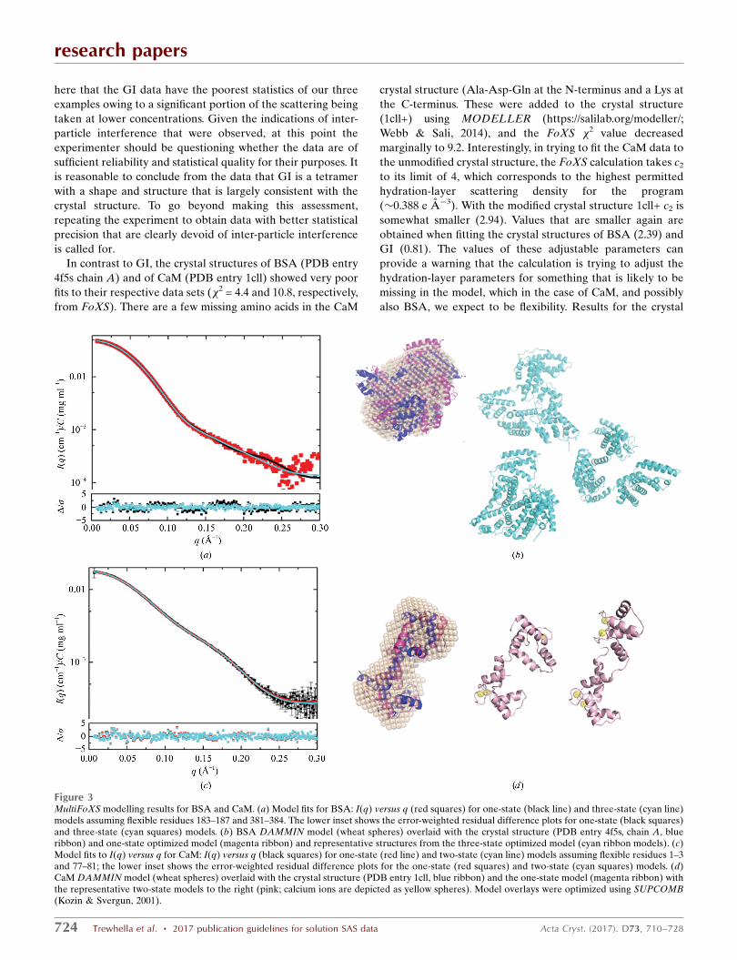
here that the GI data have the poorest statistics of our three
examples owing to a significant portion of the scattering being
taken at lower concentrations. Given the indications of inter-
particle interference that were observed, at this point the
experimenter should be questioning whether the data are of
sufficient reliability and statistical quality for their purposes. It
is reasonable to conclude from the data that GI is a tetramer
with a shape and structure that is largely consistent with the
crystal structure. To go beyond making this assessment,
repeating the experiment to obtain data with better statistical
precision that are clearly devoid of inter-particle interference
is called for.
In contrast to GI, the crystal structures of BSA (PDB entry
4f5s chain A) and of CaM (PDB entry 1cll) showed very poor
fits to their respective data sets (�2 = 4.4 and 10.8, respectively,
from FoXS). There are a few missing amino acids in the CaM
crystal structure (Ala-Asp-Gln at the N-terminus and a Lys at
the C-terminus. These were added to the crystal structure
(1cll+) using MODELLER (https://salilab.org/modeller/;
Webb & Sali, 2014), and the FoXS �2 value decreased
marginally to 9.2. Interestingly, in trying to fit the CaM data to
the unmodified crystal structure, the FoXS calculation takes c2
to its limit of 4, which corresponds to the highest permitted
hydration-layer scattering density for the program
(�0.388 e A�3). With the modified crystal structure 1cll+ c2 is
somewhat smaller (2.94). Values that are smaller again are
obtained when fitting the crystal structures of BSA (2.39) and
GI (0.81). The values of these adjustable parameters can
provide a warning that the calculation is trying to adjust the
hydration-layer parameters for something that is likely to be
missing in the model, which in the case of CaM, and possibly
also BSA, we expect to be flexibility. Results for the crystal
research papers
724 Trewhella et al. � 2017 publication guidelines for solution SAS data Acta Cryst. (2017). D73, 710–728
Figure 3MultiFoXS modelling results for BSA and CaM. (a) Model fits for BSA: I(q) versus q (red squares) for one-state (black line) and three-state (cyan line)models assuming flexible residues 183–187 and 381–384. The lower inset shows the error-weighted residual difference plots for one-state (black squares)and three-state (cyan squares) models. (b) BSA DAMMIN model (wheat spheres) overlaid with the crystal structure (PDB entry 4f5s, chain A, blueribbon) and one-state optimized model (magenta ribbon) and representative structures from the three-state optimized model (cyan ribbon models). (c)Model fits to I(q) versus q for CaM: I(q) versus q (black squares) for one-state (red line) and two-state (cyan line) models assuming flexible residues 1–3and 77–81; the lower inset shows the error-weighted residual difference plots for the one-state (red squares) and two-state (cyan squares) models. (d)CaM DAMMIN model (wheat spheres) overlaid with the crystal structure (PDB entry 1cll, blue ribbon) and the one-state model (magenta ribbon) withthe representative two-state models to the right (pink; calcium ions are depicted as yellow spheres). Model overlays were optimized using SUPCOMB(Kozin & Svergun, 2001).
structure comparisons to the data obtained using CRYSOL
(Svergun et al., 1995) also show considerable variability
in the adjustable parameters, and the �2 values from CRYSOL
are much larger for CaM, presumably because CRYSOL
models an explicit scattering contrast from the hydration
layer and the values are constrained to a particular range. The
effect of the constant adjustment to intensities in the
optimization that is an option in CRYSOL is also demon-
strated; with the extra degree of freedom, smaller �2 values
are obtained.
The overall misfits to the crystal structures for CaM and
BSA are much clearer in the error-weighted residual differ-
ence plots than in the log I(q) versus q plots of the model
overlaid with the experimental data (Fig. 2). Both BSA and
CaM are multidomain structures, and the ‘wave’ observed in
the difference plot is suggestive of a shift, on average, in the
relative positions and/or orientations of domains in solution
compared with the crystal form.
The crystal structure of BSA shows two domains stabilized
by a tight network of disulfides linked by a long flexible loop
with high temperature factors assigned to residues 183–187
and 381–384 that are proposed to be responsible for domain
movements (Bujacz, 2012). Multistate modelling using Multi-
FoXS and allowing for flexibility in these residues yielded a
much-reduced �2 of 1.05 for a one-state model and the
minimum �2 of 0.82 for a three-state model. The model I(q)
profiles for the one- and three-state models (Fig. 3a) fit within
the noise, and the residual difference plots between experi-
mental and model I(q) are significantly flatter compared with
the crystal structure fit, with a clear narrowing of the differ-
ence plot for the three-state model on the vertical scale (cyan
symbols against black). Representative models from the
research papers
Acta Cryst. (2017). D73, 710–728 Trewhella et al. � 2017 publication guidelines for solution SAS data 725
Figure 4Ensemble modelling results for CaM. (a) I(q) versus q (black squares) with the EOM model (red line) and error-weighted difference plot for the modeland experimental profiles (red squares). (b) Averaged and filtered DAMMIN model (grey spheres) overlaid with representative structures from theoptimized ensemble. Structures are aligned by their N-terminal domains (magenta), showing variability in the relative disposition of the C-terminaldomains (cyan). The calcium ions are depicted as yellow spheres. Given the variations in the selected structures, the overlay with the DAMMIN modelwas performed simply by eye in PyMOL. (c, d) Rg and dmax distributions, respectively, from EOM for the starting pool (black line) and the optimizedensemble (red line).
best-fit one- and three-state models are shown in Fig. 3(b),
with the bead model from DAMMIN overlaid with the one-
state model and the crystal structure. From the weighting
parameters, we see that the optimization has yielded the
lowest weights to the more extended structures. Thus, the
multistate modelling is supportive of the conclusions drawn
from the temperature factors in the crystal structure. However,
if one were looking to independently prove the presence of
flexible regions, the variability in solvent scattering before and
after elution of the BSA sample presents a degree of uncer-
tainty. This uncertainty should be removed by repeating the
measurements starting with freshly purchased or purified BSA
that was subjected to SEC immediately prior to SEC–SAXS.
Accounting for the missing N- and C-terminal residues and
the known flexibility in the extended helix that connects the
two globular domains of CaM [from NMR relaxation
(Barbato et al., 1992) and solution SAXS (Heidorn &
Trewhella, 1988)], MultiFoXS yields a �2 value of 0.85 with a
one-state model in which the CaM domains are on average
reoriented compared with the crystal structure to yield a
slightly more compact average Rg of 21.03 A, and a further
decrease in �2 to 0.79 is obtained with the two-state model that
includes structures with Rg values of 22.32 and 19.47 A
representing �70 and �30%, respectively, of the population.
The error-weighted residual plots for these fits are quite flat,
with a barely distinguishable narrowing of the residuals for the
two-state model (Figs. 3c and 3d). There was no improvement
in �2 for the three-state model. The alternate ensemble
modelling program for flexible systems (EOM; Bernado et al.,
2007) was also used to model CaM with the same flexible
residues, yielding a �2 value of 0.82 (the model fit is shown in
Fig. 4a). As for the multistate fits from FoXS, the residual
difference plot between experimental and model I(q) is flat,
but 13 representative structures were selected to represent the
ensemble (Fig. 4b) and this greater structural diversity in the
model is reflected in very broad distributions for Rg and dmax
(Figs. 4c and 4d, respectively) in the optimized ensemble.
The atomistic modelling thus supports the conclusions from
the dimensionless Kratky plots that BSA and CaM are both
mostly folded proteins with some flexibility, which is signifi-
cantly greater for CaM, and in each case assuming the flexible
regions identified by crystallography or NMR improved the
model fits to the data. Of note, the P-values obtained from the
CORMAP analysis (Franke et al., 2015) support the ranking of
goodness of fit for the modelling based on �2. Interestingly, the
�2 values for the best-fit models all fell within a relatively
narrow range (0.79–1.05). In contrast, the P-values varied by
an order of magnitude even though the accompanying changes
in the length of contiguous points lying on one side of the
model fit are relatively small compared with the number of
points in the data set (for CaM it was ten points at�0.165 A�1
versus eight points at �0.03 A�1 for the one-state versus
two-state models, respectively; for BSA it was 14 points at
�0.2 A�1, 12 points at �0.01 A�1 and 11 points at �0.25 A�1,
respectively). For BSA, the differences appear to be quite
subtle, and further they occur in the lowest q and high-q
regimes, unlike the statistically superior CaM example where
for the one-state model at least, the locus is in the mid-q
regime that we expect to be most sensitive to domain dispo-
sitions.
4. Conclusions
The example SEC–SAXS experiments on GI, BSA and CaM
illustrate the value of comprehensive reporting so that data
quality and model accuracy are clearly communicated.
Supplementary Table S1 provides a guide for tabulating the
recommended information for a general SAXS experiment;
such a table will be included in future releases of the IUCr
Journals Word template. Some publishers may well require
much of the reporting to be included as supplementary
material. Eventually, most of it should be made available via
the developing SAXS data and model archives. The latter will
be increasingly important for managing related data sets,
although Figs. 2, 3, 4 and 5 in Carter et al. (2015) show how
effectively one can assemble the results for multiple data sets.
It is evident that the often-ignored adjustable parameters
enhance the understanding of potential limitations in models.
In this regard, it is noted that for some programs it is not
straightforward to relate the adjustable parameters to the
physical model. It would be desirable for the developers of
programs for SAS modelling to make information on the
adjustable parameters more transparent and their values
readily available in standard output formats.
The three data sets analyzed highlight advances in SEC–
SAXS and the analysis of multistate ensembles. Both the GI
and BSA samples were not subjected to purification steps
before loading onto the SEC–SAXS column. For GI the data
statistics were relatively poor, and there was evidence of
incompletely removed inter-particle interference in the scat-
tering. For BSA there were issues with the solvent subtraction.
These limitations were transparent in the reporting and the
modelling and interpretation appropriate in that context.
For experiments aimed at hybrid modelling, for example
improving the solution structure by co-refinement with NMR
data, these limitations would be unacceptable and the SAS
experiments should be repeated after taking steps to purify
the proteins before SEC–SAXS and to optimize the condi-
tions to obtain better quality data that are free of the issues
encountered.
The CaM sample was highly purified and well characterized
before SEC–SAXS and as a result delivered a superior data
set in spite of its relatively small size and hence weaker total
scattering power. CaM is a well characterized protein struc-
turally, including its regions of flexibility, and the SAXS data
were well fitted using multistate/ensemble modelling. An open
question for multistate/ensemble modelling is whether to
present the minimum number of structures that the data can
support, or whether one should assume that flexible sequences
will sample a continuous distribution of conformations and so
a larger number in the representative set may be justified. At
this time, a variety of programs allow investigators to choose
their preferred multistate/ensemble modelling approach and
assumptions.
research papers
726 Trewhella et al. � 2017 publication guidelines for solution SAS data Acta Cryst. (2017). D73, 710–728
Accurate propagation of uncertainties is an important area
for further work in the community for SAS data to contribute
to integrative/hybrid modelling. For synchrotron SAXS data,
the increasing brightness of the sources has reduced the
relative random statistical errors in the data to the extent that
they may no longer dominate and systematic errors can
become significant. A recent model has been proposed and
tested for optimizing experimental setups and taking into
account not just random statistical errors, but those originating
from setup geometry and the physics of the measurement
process (Sedlak et al., 2017). The �2 values near 1 for the best-
fit models in our example set were all near the expected value
for a fit within the random statistical errors propagated, and
notably the superior CaM sample with its statistically superior
data set resulted in models with the lowest �2 values and no
evidence of systematic errors owing to sample issues or solvent
mismatch.
The error-independent CORMAP P-value for model fits
correlated well with the �2 values, showing a much larger
range of variation. Broader experience with a large number of
examples is needed to provide a basis for understanding the
significance of the absolute value of the P-values in the
context of SAS modelling. We therefore encourage experi-
menters to use the CORMAP analysis and to report the P-
values. Once a sufficiently large sample size has been acquired,
a systematic review and evaluation of their utility in the
context of SAS modelling will be possible.
As biomolecular SAS continues to grow in popularity and
further develop in this era of integrative/hybrid methods for
the structure determination of increasingly complex bio-
molecular complexes and assemblies, it is essential to firmly
establish publication guidelines with the goal of ensuring
access to the information required for proper evaluation of the
quality of SAS samples and data, as well as the validity of
structural interpretation. In addition to our recommended
guidelines for data presentation in a publication, we recom-
mend that SAS data and models be deposited and made freely
available in a public data bank [currently there is SASBDB
and BIOISIS (http://www.bioisis.net/)]. Ideally q, I(q) with
standard errors should be deposited for each measured profile
and the associated models plus details of how the experiment
was conducted with the data and model validation parameters
and analyses as outlined above. We strongly recommend that
the sasCIF dictionary be expanded to include all of these data
items in the recommended guidelines and encourage program
developers to use the sasCIF as an export format which will
significantly ease the burden on researchers in reporting, and
will facilitate more automated deposition SAS databases that
can support integrative/hybrid models (Sali et al., 2015).
Utilizing the sasCIF will also enable seamless data exchange
and interoperability with other structural biology data
resources, including the Protein Data Bank.
Acknowledgements
We wish to thank Helen Berman for her critical reading of the
manuscript, for her insightful comments and for her continued
support of our efforts in this work.
References
Allen, A. J., Zhang, F., Kline, R. J., Guthrie, W. F. & Ilavsky, J. (2017).J. Appl. Cryst. 50, 462–474.
Appolaire, A., Girard, E., Colombo, M., Dura, M. A., Moulin, M.,Hartlein, M., Franzetti, B. & Gabel, F. (2014). Acta Cryst. D70,2983–2993.
Babu, Y. S., Bugg, C. E. & Cook, W. J. (1988). J. Mol. Biol. 204,191–204.
Barbato, G., Ikura, M., Kay, L. E., Pastor, R. W. & Bax, A. (1992).Biochemistry, 31, 5269–5278.
Bergmann, A., Orthaber, D., Scherf, G. & Glatter, O. (2000). J. Appl.Cryst. 33, 869–875.
Berlin, K., Castaneda, C. A., Schneidman-Duhovny, D., Sali, A.,Nava-Tudela, A. & Fushman, D. (2013). J. Am. Chem. Soc. 135,16595–16609.
Berman, H. M., Bhat, T. N., Bourne, P. E., Feng, Z., Gilliland, G.,Weissig, H. & Westbrook, J. (2000). Nature Struct. Biol. 7, 957–959.
Bernado, P., Mylonas, E., Petoukhov, M. V., Blackledge, M. &Svergun, D. I. (2007). J. Am. Chem. Soc. 129, 5656–5664.
Bernado, P., Perez, Y., Svergun, D. I. & Pons, M. (2008). J. Mol. Biol.376, 492–505.
Berthaud, A., Manzi, J., Perez, J. & Mangenot, S. (2012). J. Am.Chem. Soc. 134, 10080–10088.
Bizien, T., Durand, D., Roblina, P., Thureau, A., Vachette, P. & Perez,J. (2016). Protein Pept. Lett. 23, 217–231.
Blanchet, C. E., Spilotros, A., Schwemmer, F., Graewert, M. A.,Kikhney, A., Jeffries, C. M., Franke, D., Mark, D., Zengerle, R.,Cipriani, F., Fiedler, S., Roessle, M. & Svergun, D. I. (2015). J. Appl.Cryst. 48, 431–443.
Bras, W., Koizumi, S. & Terrill, N. J. (2014). IUCrJ, 1, 478–491.Brennich, M. E., Round, A. R. & Hutin, S. (2017). J. Vis. Exp., e54861.Brookes, E., Perez, J., Cardinali, B., Profumo, A., Vachette, P. &
Rocco, M. (2013). J. Appl. Cryst. 46, 1823–1833.Brookes, E., Vachette, P., Rocco, M. & Perez, J. (2016). J. Appl. Cryst.
49, 1827–1841.Bujacz, A. (2012). Acta Cryst. D68, 1278–1289.Carter, L., Kim, S. J., Schneidman-Duhovny, D., Stohr, J., Poncet-
Montange, G., Weiss, T. M., Tsuruta, H., Prusiner, S. B. & Sali, A.(2015). Biophys. J. 109, 793–805.
Chen, P.-C. & Hub, J. S. (2015). Biophys. J. 108, 2573–2584.David, G. & Perez, J. (2009). J. Appl. Cryst. 42, 892–900.Debye, P. (1947). J. Phys. Colloid Chem. 51, 18–32.Debye, P., Anderson, H. R. Jr & Brumberger, H. (1957). J. Appl.
Phys. 28, 679–683.Durand, D., Vives, C., Cannella, D., Perez, J., Pebay-Peyroula, E.,
Vachette, P. & Fieschi, F. (2010). J. Struct. Biol. 169, 45–53.Engelman, D. M. & Moore, P. B. (1975). Annu. Rev. Biophys. Bioeng.
4, 219–241.Feigin, L. A. & Svergun, D. I. (1987). Structure Analysis by Small-
Angle X-ray and Neutron Scattering, ch. 3, pp. 68–73. New York:Plenum Press.
Fischer, H., de Oliveira Neto, M., Napolitano, H. B., Polikarpov, I. &Craievich, A. F. (2010). J. Appl. Cryst. 43, 101–109.
Franke, D., Jeffries, C. M. & Svergun, D. I. (2015). Nature Methods,12, 419–422.
Franke, D. & Svergun, D. I. (2009). J. Appl. Cryst. 42, 342–346.Gabel, F. (2012). Eur. Biophys. J. 41, 1–11.Gasteiger, E., Hoogland, C., Gattiker, A., Duvaud, S., Wilkins, M. R.,
Appel, R. D. & Bairoch, A. (2005). The Proteomics ProtocolsHandbook, edited by J. M. Walker, pp. 571–607. Totowa: HumanaPress.
Glatter, O. (1977). J. Appl. Cryst. 10, 415–421.Glatter, O. & Kratky, O. (1982). Small-Angle X-ray Scattering.
London: Academic Press.Graewert, M. A., Franke, D., Jeffries, C. M., Blanchet, C. E., Ruskule,
D., Kuhle, K., Flieger, A., Schafer, B., Tartsch, B., Meijers, R. &Svergun, D. I. (2015). Sci. Rep. 5, 10734.
research papers
Acta Cryst. (2017). D73, 710–728 Trewhella et al. � 2017 publication guidelines for solution SAS data 727
Grishaev, A., Guo, L., Irving, T. & Bax, A. (2010). J. Am. Chem. Soc.132, 15484–15486.
Grishaev, A., Tugarinov, V., Kay, L. E., Trewhella, J. & Bax, A. (2008).J. Biomol. NMR, 40, 95–106.
Guinier, A. (1939). Ann. Phys. 11, 161–237.Harpaz, Y., Gerstein, M. & Chothia, C. (1994). Structure, 2, 641–649.Heidorn, D. B. & Trewhella, J. (1988). Biochemistry, 27, 909–915.Hura, G. L., Budworth, H., Dyer, K. N., Rambo, R. P., Hammel, M.,
McMurray, C. T. & Tainer, J. A. (2013). Nature Methods, 10,453–454.
Ibrahim, Z., Martel, A., Moulin, M., Kim, H. S., Hartlein, M.,Franzetti, B. & Gabel, F. (2017). Sci. Rep. 7, 40948.
Jacques, D. A., Guss, J. M., Svergun, D. I. & Trewhella, J. (2012). ActaCryst. D68, 620–626.
Jacques, D. A., Guss, J. M. & Trewhella, J. (2012). BMC Struct. Biol.12, 9.
Jacrot, B. (1976). Rep. Prog. Phys. 39, 911–953.Jacrot, B. & Zaccai, G. (1981). Biopolymers, 20, 2413–2426.Jeffries, C. M., Graewert, M. A., Blanchet, C. E., Langley, D. B.,
Whitten, A. E. & Svergun, D. I. (2016). Nature Protoc. 11, 2122–2153.
Jordan, A., Jacques, M., Merrick, C., Devos, J., Forsyth, V. T., Porcar,L. & Martel, A. (2016). J. Appl. Cryst. 49, 2015–2020.
Kachala, M., Westbrook, J. & Svergun, D. (2016). J. Appl. Cryst. 49,302–310.
Kikhney, A. G. & Svergun, D. I. (2015). FEBS Lett. 589, 2570–2577.Kim, H. S. & Gabel, F. (2015). Acta Cryst. D71, 57–66.Kirby, N., Cowieson, N., Hawley, A. M., Mudie, S. T., McGillivray,
D. J., Kusel, M., Samardzic-Boban, V. & Ryan, T. M. (2016). ActaCryst. D72, 1254–1266.
Kirby, N. M., Mudie, S. T., Hawley, A. M., Cookson, D. J., Mertens,H. D. T., Cowieson, N. & Samardzic-Boban, V. (2013). J. Appl.Cryst. 46, 1670–1680.
Koch, M. H. J. & Stuhrmann, H. B. (1979). Methods Enzymol. 59,670–706.
Konarev, P. V. & Svergun, D. I. (2015). IUCrJ, 2, 352–360.Konarev, P. V., Volkov, V. V., Sokolova, A. V., Koch, M. H. J. &
Svergun, D. I. (2003). J. Appl. Cryst. 36, 1277–1282.Kozin, M. B. & Svergun, D. I. (2001). J. Appl. Cryst. 34, 33–41.Kratky, O. (1982). Small-Angle X-ray Scattering, edited by O. Glatter
& O. Kratky, pp. 361–386. London: Academic Press.Malfois, M. & Svergun, D. I. (2000). J. Appl. Cryst. 33, 812–816.Mathew, E., Mirza, A. & Menhart, N. (2004). J. Synchrotron Rad. 11,
314–318.Meisburger, S. P., Taylor, A. B., Khan, C. A., Zhang, S., Fitzpatrick,
P. F. & Ando, N. (2016). J. Am. Chem. Soc. 138, 6506–6516.Michie, K. A., Kwan, A. H., Tung, C.-S., Guss, J. M. & Trewhella, J.
(2016). Structure, 24, 2000–2007.Moore, P. B. (1980). J. Appl. Cryst. 13, 168–175.Mylonas, E. & Svergun, D. I. (2007). J. Appl. Cryst. 40, s245–s249.Orthaber, D., Bergmann, A. & Glatter, O. (2000). J. Appl. Cryst. 33,
218–225.Pelikan, M., Hura, G. L. & Hammel, M. (2009). Gen. Physiol.
Biophys. 28, 174–189.Perkins, S. J. (1986). Eur. J. Biochem. 157, 169–180.Perkins, S. J., Wright, D. W., Zhang, H., Brookes, E. H., Chen, J.,
Irving, T. C., Krueger, S., Barlow, D. J., Edler, K. J., Scott, D. J.,Terrill, N. J., King, S. M., Butler, P. D. & Curtis, J. E. (2016). J. Appl.Cryst. 49, 1861–1875.
Petoukhov, M. V., Billas, I. M., Takacs, M., Graewert, M. A., Moras, D.& Svergun, D. I. (2013). Biochemistry, 52, 6844–6855.
Petoukhov, M. V., Franke, D., Shkumatov, A. V., Tria, G., Kikhney,A. G., Gajda, M., Gorba, C., Mertens, H. D. T., Konarev, P. V. &Svergun, D. I. (2012). J. Appl. Cryst. 45, 342–350.
Petoukhov, M. V. & Svergun, D. I. (2015). Acta Cryst. D71, 1051–1058.
Porod, G. (1951). Kolloid-Z. 124, 83–114.Ramagopal, U. A., Dauter, M. & Dauter, Z. (2003). Acta Cryst. D59,
868–875.Rambo, R. P. & Tainer, J. A. (2011). Biopolymers, 95, 559–571.Rambo, R. P. & Tainer, J. A. (2013a). Annu. Rev. Biophys. 42, 415–
441.Rambo, R. P. & Tainer, J. A. (2013b). Nature (London), 496, 477–
481.Reis, M. A. dos, Aparicio, R. & Zhang, Y. (2011). Biophys. J. 101,
2770–2781.Sali, A. et al. (2015). Structure, 23, 1156–1167.Schneidman-Duhovny, D., Hammel, M., Tainer, J. A. & Sali, A.
(2013). Biophys. J. 105, 962–974.Schneidman-Duhovny, D., Hammel, M., Tainer, J. A. & Sali, A.
(2016). Nucleic Acids Res. 44, W424–W429.Schneidman-Duhovny, D., Kim, S. J. & Sali, A. (2012). BMC Struct.
Biol. 12, 17.Schneidman-Duhovny, D., Pellarin, R. & Sali, A. (2014). Curr. Opin.
Struct. Biol. 28, 96–104.Schwieters, C. D. & Clore, G. M. (2014). Prog. Nucl. Magn. Reson.
Spectrosc. 80, 1–11.Sedlak, S. M., Bruetzel, L. K. & Lipfert, J. (2017). J. Appl. Cryst. 50,
621–630.Skou, S., Gillilan, R. E. & Ando, N. (2014). Nature Protoc. 9, 1727–
1739.Spinozzi, F., Ferrero, C., Ortore, M. G., De Maria Antolinos, A. &
Mariani, P. (2014). J. Appl. Cryst. 47, 1132–1139.Stuhrmann, H. B. (1980). Synchrotron Radiation Research, edited by
H. Winick & S. Doniach, pp. 513–531. New York: Springer.Svergun, D. I. (1992). J. Appl. Cryst. 25, 495–503.Svergun, D. I. (1999). Biophys. J. 76, 2879–2886.Svergun, D., Barberato, C. & Koch, M. H. J. (1995). J. Appl. Cryst. 28,
768–773.Svergun, D. I., Koch, M. H. J., Timmins, P. A. & May, R. P. (2013).
Small-Angle X-ray and Neutron Scattering from Biological Macro-molecules, ch. 3. Oxford University Press.
Svergun, D. I., Richard, S., Koch, M. H. J., Sayers, Z., Kuprin, S. &Zaccai, G. (1998). Proc. Natl Acad. Sci. USA, 95, 2267–2272.
Terakawa, T., Higo, J. & Takada, S. (2014). Biophys. J. 107, 721–729.
Trewhella, J., Hendrickson, W. A., Kleywegt, G. J., Sali, A., Sato, M.,Schwede, T., Svergun, D. I., Tainer, J. A., Westbrook, J. & Berman,H. M. (2013). Structure, 21, 875–881.
Tria, G., Mertens, H. D. T., Kachala, M. & Svergun, D. I. (2015).IUCrJ, 2, 207–217.
Tuukkanen, A. T., Kleywegt, G. J. & Svergun, D. I. (2016). IUCrJ, 3,440–447.
Vad, T. & Sager, W. F. C. (2011). J. Appl. Cryst. 44, 32–42.Valentini, E., Kikhney, A. G., Previtali, G., Jeffries, C. M. & Svergun,
D. I. (2015). Nucleic Acids Res. 43, D357–D363.Webb, B. & Sali, A. (2014). Curr. Protoc. Bioinformatics, 47, Unit 5.6.
https://doi.org/10.1002/0471250953.bi0506s47.Whitten, A. E., Cai, S. & Trewhella, J. (2008). J. Appl. Cryst. 41,
222–226.Yang, S., Blachowicz, L., Makowski, L. & Roux, B. (2010). Proc. Natl
Acad. Sci. USA, 107, 15757–15762.Yang, Z., Lasker, K., Schneidman-Duhovny, D., Webb, B., Huang,
C. C., Pettersen, E. F., Goddard, T. D., Meng, E. C., Sali, A. &Ferrin, T. E. (2012). J. Struct. Biol. 179, 269–278.
Zhang, F., Roosen-Runge, F., Skoda, M. W., Jacobs, R. M., Wolf, M.,Callow, P., Frielinghaus, H., Pipich, V., Prevost, S. & Schreiber, F.(2012). Phys. Chem. Chem. Phys. 14, 2483.
research papers
728 Trewhella et al. � 2017 publication guidelines for solution SAS data Acta Cryst. (2017). D73, 710–728