32
2017 FSAE Rules Changes Michael & Suzanne Royce Albion Associates, LLC
2017 FSAE Rules Changes
Michael & Suzanne RoyceAlbion Associates, LLC

• 2017 is a “major change” year
• Rules were published in June at www.fsaeonline.com
• Updated September 2 2016
• Non USA events will all publish their own Supplementary
Rules.
2017 FSAE – Rules

• Not all rules changes are covered in this presentation
• In the version published in June 2016, all changes from the 2016 rules were
identified with a vertical bar on the right hand side of the page. This covered
formatting and typo corrections as well as actual rules changes. This vertical
bar was NOT in the latest version (Rev. A) dated September 2nd 2016.
FSAE – 2017 Rules Changes

Definitions of Terms Used in the Rules• “Must” designates a requirement.• “Should” gives a recommendation• “May” gives permission, neither a requirement or a
recommendation
2017 Rules Changes, FSAE IC & EV

A1.2.2 The vehicle must accommodate drivers whose stature ranges from 5th percentile female to 95th percentile male and must satisfy the requirements of the Formula SAE Rules.
Driver accommodation includes but is not limited to: driver visibility, steering wheel and shifter locations, pedals, lap and shoulder belt angles and head rest position. Detailed anthropometric data for the 5th percentile female and 95th percentile male may be found on the FSAE websitehttp://fsaeonline.com/.
2017 Rules Changes, FSAE IC & EVA1.2.2 Vehicle Design

Dynamic Events• Acceleration 100 (was 75)• Skid-Pad 75 (was 50)• Autocross 125 (was 150)• Efficiency 100• Endurance 275 (was 300)
Total for Dynamics 675 (unchanged)
2017 Rules Changes, FSAE IC & EV A1.4.1 Event Points
• T3.14.7 The Front Hoop braces must be straight, i.e. without any bends
2017 Rules Changes, FSAE IC & EVT3.14
• Text added to clarify the intent of the rule to ensure effective load transfer from the Front Bulkhead through the Side-Impact Structure back to the Main Hoop.
• If the upper SIS tube meets the Front Hoop outside the allowable zone, then additional bracing is required
The revised wording is:T3.19.2 The Front Bulkhead must be supported back to the Front Roll Hoop by a minimum of three Frame Members on each side of the vehicle; an upper member; lower member and diagonal brace to provide triangulation.
a. The upper support member must be attached within 50mm (2”) of the top surface of the Front Bulkhead, and attach to the Front Roll Hoop within a zone extending 100mm (4”) above and 50mm (2”) below the Upper Side Impact member. If the upper support member is further than 100mm (4”) above the Upper Side Impact member, then properly triangulated bracing is required to transfer load to the Main Hoop, either via the Upper Side Impact member, or an additional member that meets the size requirements of T3.4, transmitting load from the junction of the Upper Support Member with the Front Hoop
2017 Rules Changes, FSAE IC & EVT3.19.2 Front Bulkhead Support
Rules rewritten so they have a logical flow and more clearly identify the requirements for IA attachments.
• T3.20.1 Defines the Impact Attenuator Assembly, as consisting of an Impact Attenuator and an Anti-Intrusion Plate.
• T3.20.2 mentions the “standard” FSAE IA.• T3.20.4 has specifics on the attachment of the IA Assembly to the Front
Bulkhead, including:• T3.20.4.a for welding the IA Assembly to the Front Bulkhead.• T3.20.4.b increases the number of bolts for a bolted attachment from
4 to 8 M8 fasteners.• T3.20.5 & T3.20.6 further define how the IA Assembly must be attached.
Those involved with the IA, read the revised rules carefully.
2017 Rules Changes, FSAE IC & EVT3.20 Impact Attenuator

T3.21 has also been significantly re-written, including:
T3.21.2 The report must include:a. Test data that proves ….b. Calculations showing how the reported absorbed energy and decelerations have been derived.c. A schematic of the test method.d. Photos of the attenuator, annotated with the height of the attenuator before and after testing.
Teams using the standard Impact Attenuator are not required to submit test data with their IAD Report, but all other requirements must be included. In addition, photos of the actual attenuator and evidence that it meets the design criteria in Appendix T-3 must be appended to the report.
Teams should review T3.21.3 through T3.21.6 very carefully to review the test requirements, especially if they have a front wing.
2017 Rules Changes, FSAE IC & EVT3.21 IA Testing & Data Report

Expanded to separate the requirements inside and outside the primary structure.• Requires a 25mm minimum clearance inside the primary structure to
account for the allowable anti-intrusion plate deflection.• Objects outside the primary structure must be included in the IA
dynamic test, subject to an analysis approach or fall with in the an allowable zone defined by the crushed height of the impact attenuator.
Now reads:T3.22.1 All non-crushable objects (e.g. batteries, master cylinders, hydraulic reservoirs) inside the primary structure must have 25 mm (1”) clearance to the rear face of the Impact Attenuator Anti-Intrusion Plate.
T3.22.2 All non-crushable objects outside the primary structure must be either:
a. Included in the Impact Attenuator physical testb. Subject to an analysis approach as per T3.21.6 b) or T3.21.6 c)c. Mounted rearwards of an imaginary transverse vertical plane, offset forwards from the Impact Attenuator Anti-Intrusion Plate by a distance equal to the height of the crushed impact attenuator.
2017 Rules Changes, FSAE IC & EVT3.22 Non-Crushable Objects

T3.24.3 The locations for the three (3) required tubular members are as follows:a. The upper Side Impact Structural member must connect the Main Hoop and the Front Hoop.
With a 77kg (170 pound) driver seated in the normal driving position all of the member must be at a height between 300 mm (11.8 inches) and 350 mm (13.8 inches) above the ground. The upper frame rail may be used as this member if it meets the height, diameter and thickness requirements.
If the member is bent or non-continuous, the minimum tube size must be 1 3/8” x 0.047” (35mm x 1.2 mm) or equivalent.
2017 Rules Changes, FSAE IC & EVT3.24.3 Side Impact

• T3.27.4 and T3.30.6 added to define quasi-isotropic lay-ups and how they must be tested.
• T3.37 IA Attachment – must now be equivalent to eight 8 mm metric 8.8 bolts (was 4).
• T3.39.2 Monocoque Attachments - Proof now that the brackets are adequately stiff must be documented in the SES. Hand calculations, or FEA with supporting hand calculations are both acceptable. The use of FEA alone is not acceptable
• T3.40.4.b Harness Attachment Point Testing - Loads must be applied normal to the test sample.
2017 Rules Changes, FSAE IC & EVMonocoque Changes
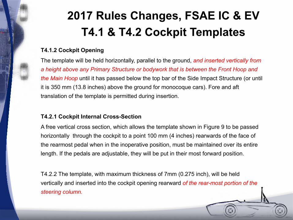
T4.1.2 Cockpit Opening
The template will be held horizontally, parallel to the ground, and inserted vertically from a height above any Primary Structure or bodywork that is between the Front Hoop and the Main Hoop until it has passed below the top bar of the Side Impact Structure (or until it is 350 mm (13.8 inches) above the ground for monocoque cars). Fore and aft translation of the template is permitted during insertion.
T4.2.1 Cockpit Internal Cross-Section
A free vertical cross section, which allows the template shown in Figure 9 to be passed horizontally through the cockpit to a point 100 mm (4 inches) rearwards of the face of the rearmost pedal when in the inoperative position, must be maintained over its entire length. If the pedals are adjustable, they will be put in their most forward position.
T4.2.2 The template, with maximum thickness of 7mm (0.275 inch), will be held vertically and inserted into the cockpit opening rearward of the rear-most portion of the steering column.
2017 Rules Changes, FSAE IC & EVT4.1 & T4.2 Cockpit Templates

• T5.1.3 – SFI belts now ”good” for 5 years (was 2 years).
• T5.2.2.e Where a single shear tab is welded to the chassis, the tab to tube welding must be on both sides of the base of the tab.
• Note: Double shear attachments are preferred. Where possible the tabs and brackets for double shear mounts should also be welded on both sides.
• T5.3.2 The lap belts must not be routed over the sides of the seat. The belts must come through the seat at the bottom of the sides of the seat to maximize the wrap of the pelvic surface and continue in a straight line to the anchorage point. (Was “should” in both cases).
2017 Rules Changes, FSAE IC & EVDriver’s Harness & Mounting
Harness Mounting Bolts• T5.3.7 Any bolt used to attach a lap belt, either directly to the
chassis or to an intermediate bracket, must be a minimum of 10mm Metric Grade 8.8 (3/8 inch SAE Grade 5)
• T5.4.5 Any bolt used to attach a shoulder harness belt, either directly to the chassis or to an intermediate bracket, must be a minimum of 10mm Metric Grade 8.8 (3/8 inch SAE Grade 5)
• T5.5.3 Any bolt used to attach an anti-submarine belt, either directly to the chassis or to an intermediate bracket, must be a minimum of 8mm Metric Grade 8.8 (5/16 inch SAE Grade 5)
2017 Rules Changes, FSAE IC & EVDriver’s Harness & Mounting- Cont’d
The shoulder harness must be mounted behind the driver to a single piece of
uncut, continuous, closed section steel tubing that meets the requirements of
T3.4.1. This Shoulder Harness Mounting Bar must attach to the Main Hoop on
both sides of the chassis. Bends in the Shoulder Harness Mounting Bar, if
present, must be smooth and continuous with no evidence of crimping or wall
failure.
Bent Shoulder Harness Mounting Bars are required to have bracing members
attached at the bends and to the Main Hoop. Material for this bracing must
meet the requirements of T3.4.1 “Shoulder Harness Mounting Bar Bracing.”
The included angle in side view between the Shoulder Harness Bar and the
braces must be no less than 30 degrees.
2017 Rules Changes, FSAE IC & EVT5.4.1 Shoulder Harness Bar

T5.5.1 The anti-submarine belt of a 5-point harness must be mounted in line with, or angled slightly forward (up to twenty degrees (20°)) of, the driver’s chest-groin line.
T5.5.2 The anti-submarine belts of a 6-point harness must be mounted either:
a. With the belts going vertically down from the groin, or angled up to twenty degrees (20°) rearwards. The anchorage points should be approximately 100 mm (4 inches) apart. Orb. With the anchorage points on the Primary Structure at or near the lap belt anchorages, the driver sitting on the anti-submarine belts, and the belts coming up around the groin to the release buckle.
”Must” was “should”.
2017 Rules Changes, FSAE IC & EVT5.5 Sub-Belt Mounting

20o
2017 Rules Changes, FSAE IC & EVT5.5 Sub-Belt Mounting, 5 Point
T5.5.1 The anti-submarine belt of a 5-point harness mustbe mounted in line with, or angled slightly forward (up to twenty degrees (20°)) of, the driver’s chest-groin line.
2017 Rules Changes, FSAE IC & EVT5.5 Sub-Belt Mounting, 6 Point
20o
appr
ox.
100
- 150
mm
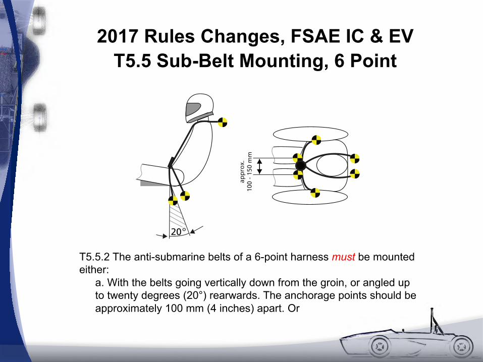
T5.5.2 The anti-submarine belts of a 6-point harness must be mounted either:
a. With the belts going vertically down from the groin, or angled up to twenty degrees (20°) rearwards. The anchorage points should be approximately 100 mm (4 inches) apart. Or

2017 Rules Changes, FSAE IC & EVT5.5 Sub-Belt Mounting, 6 point
Orb. With the anchorage points on the Primary Structure at or near the lap belt anchorages, the driver sitting on the anti-submarine belts, and the belts coming up around the groin to the release buckle.

T9.1 Aerodynamic Device Locations
• Text has been added confirming the exclusion zones in T2.1 apply to all sections of Article 9.
And for Front Wing Endplates
• T9.2.2 When viewed from the front of the vehicle, the part of the front
wheels/tires that are more than 250 mm (9.8 inches) above ground
level must be unobstructed. by any part of the aerodynamic device,
with the exception of any vertical surfaces (end plates) less than 25
mm in thickness.
2017 Rules Changes, FSAE IC & EVT9 Aero Rules

T11.1.2 The use of button head cap, countersunk head, pan head, flat head
or round head screws or bolts is prohibited in ANY location in the following
systems. Hexagonal recessed drive screws or bolts (sometimes called
Socket head cap screws or Allen screws/bolts) are permitted:
a) Primary Structure attachments
b) Impact attenuator attachment
c) Driver’s harness attachment
d) Steering system
e) Brake system
f) Suspension system
2017 Rules Changes, FSAE IC & EVT11 Fasteners

The 2017 Rules say:• T12.1.3 The approved transponder type(s) will be provided
on the competition website.
Previously, the MYLAPS Car/Bike and AMB TranX260 transponders were specified.
2017 Rules Changes, FSAE IC & EVT12 Transponder
• Snell K2000, M2000 and SA2000 helmets dropped.
• Snell SAH2010, K2015, M2015, SA2015 helmets added.
• FIA 8859-2015 added.
2017 Rules Changes, FSAE IC & EVT14.2 Helmets
• IC1.1 Maximum engine displacement increased from 610 ccs to 710 ccs.
• IC1.11 - IC1.17 – ETC rules – major re-write.
• IC2.6.1 Fuel Tank Filler Neck – Minimum filler neck ID reduced from 38 mm to 35 mm.
• IC3.2.3 Noise Test – Restrictions on active or adjustable tuning devices.
• IC3.3 Idle noise level now 103 dBC (was 100 dBC)
• IC4.1.2 – Alternator field wire must be cut by master switch.
2017 Rules Changes, FSAE IC & EVIC Engine Changes

• EV2.3 Accelerator Pedal Position Sensor, EV2.4 Brake System Encoder & EV2.5 Brake Pedal Plausibility Check – major re-writes.
§ EV3.3.3 Maintenance Plugs - It must not be physically possible to connect the Maintenance Plugs in any way other than the design intent configuration.
§ EV3.4.6 and EV3.4.8 Accumulator Container and Mounting – Read carefully, some significant changes including a reduction of the maximum weight per walled section of Accumulator Containers from 15kg to 12kg.
§ EV5.8 Charging Shutdown Circuit – Complete new section.
2017 FSAE Rules EV Changes
• EV5.8 Charging Shutdown Circuit – Complete new section.
• EV3.4.7 – Low Voltage Battery- Adoption of 2015 Rules Clarification that was missed in 2016 rules.- Must comply with IC4.4.4 (requirements for lithium batteries).
• EV5.1.3 – Shutdown Circuit- No cell balancing when accumulator isolation relays are open.- This prohibits the use of DCDC converter before the contactor in place of a GLV battery.
2017 FSAE Rules EV Changes – Cont’d

• Presentation Event S5.1.6 & S5.1.7 – Emphasis on based on the car entered in the competition.
2017 Rules Changes, FSAE IC & EVStatic Events

Acknowledgement: Some material provided by Dan Jones, Formula Student
Questions?
Copyright © 2017, Albion Associates, LLC.All rights reserved.


