31
Presenter: Dave Galbraith Variable Speed Drives Controlling Centrifugal Pumps Energy Savings 2018 Clean and Safe Drinking Water Workshop Hotel Gander
Presenter:Dave Galbraith
Variable Speed DrivesControlling Centrifugal Pumps
Energy Savings
2018 Clean and Safe Drinking Water WorkshopHotel Gander
What is a Variable Speed (Frequency) Drive?
AKA… VFD, VSD, ASD, Drive, Inverter, Converter, etc.
A VFD converts the 50-60Hz fixed-frequency and fixed-voltage AC power supply into a DC supply, using an integrated rectifier.
Integrated power electronics then inverts the DC supply into a simulated PWM sinusoidal output with continuously variable frequency and voltage, which is used to drive the motor.
Converters = change AC to DCInverters = change DC to AC
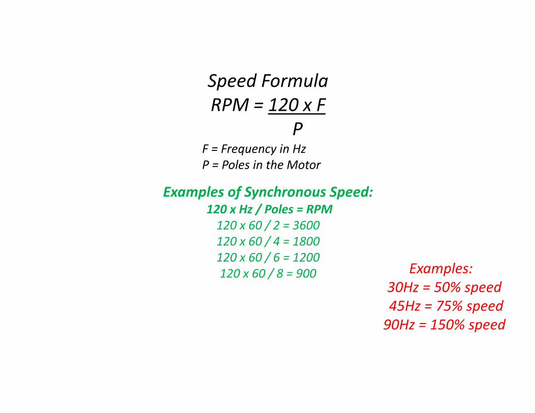
Speed FormulaRPM = 120 x F
PF = Frequency in HzP = Poles in the Motor
Examples of Synchronous Speed:120 x Hz / Poles = RPM120 x 60 / 2 = 3600120 x 60 / 4 = 1800120 x 60 / 6 = 1200120 x 60 / 8 = 900 Examples:
30Hz = 50% speed45Hz = 75% speed90Hz = 150% speed
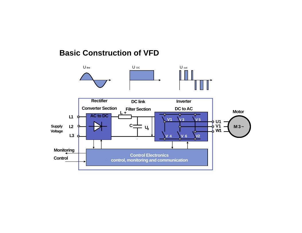
Basic Construction of VFDU line U DC U out
L1
Supply Voltage
L3
Monitoring
Control
RectifierConverter Section
AC to DC
Control Electronics control, monitoring and communication
L +
DC linkFilter Section
C
•-
Ud
V1 V 3 V 5
V 4 V 6
InverterDC to AC
V2
U1V1W1
Motor
M 3 ~ L2
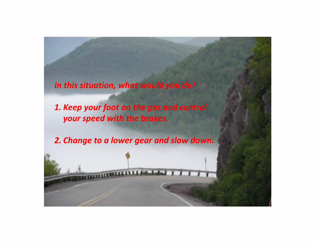
In this situation, what would you do?
1. Keep your foot on the gas and control your speed with the brakes.
2. Change to a lower gear and slow down.
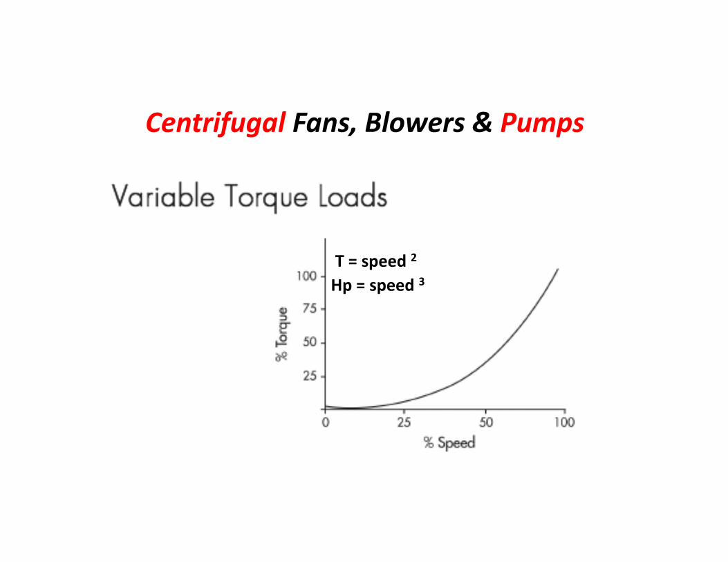
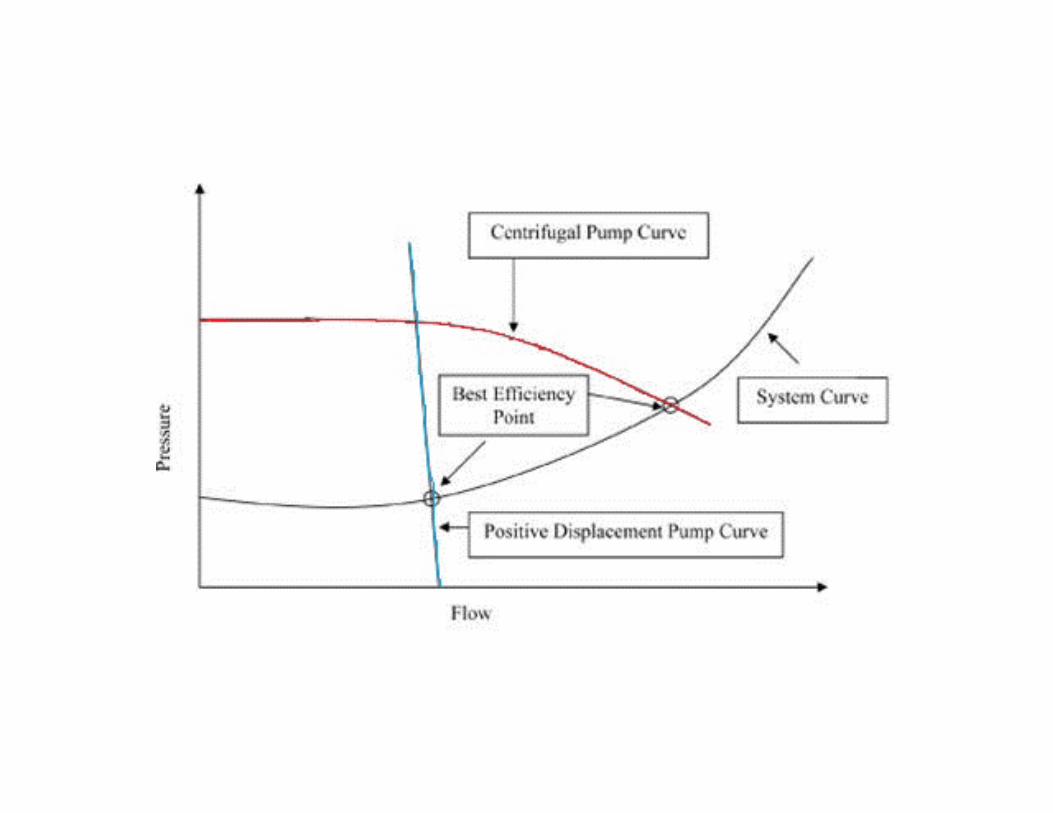
Centrifugal Fans, Blowers & Pumps
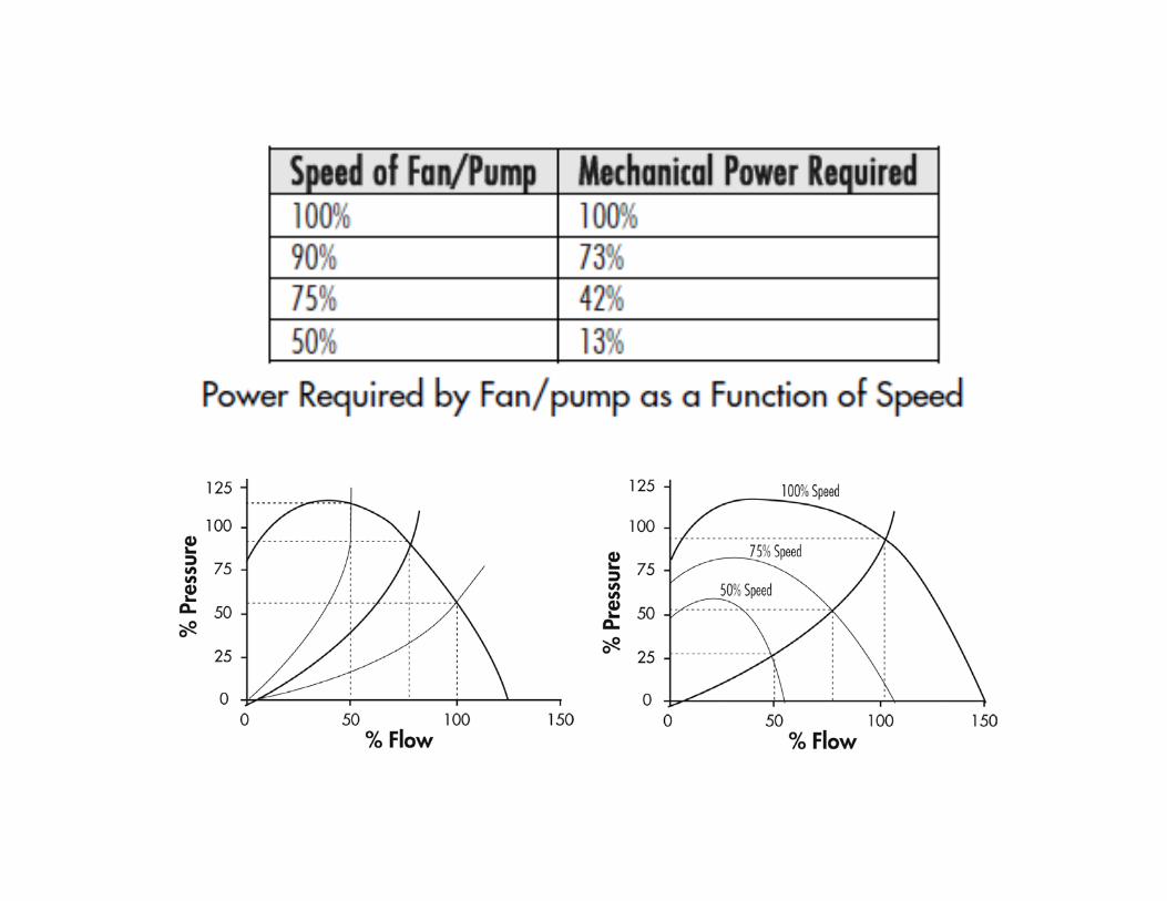
Hp = speed 3T = speed 2
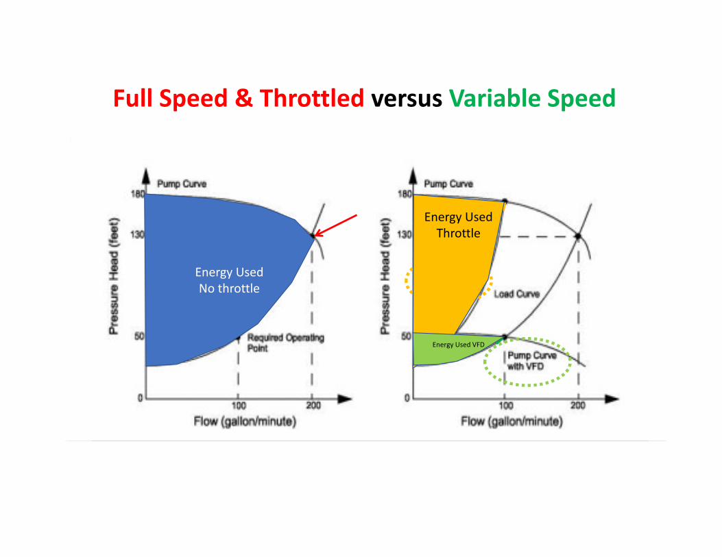
Energy UsedThrottle
Energy UsedNo throttle
Energy Used VFD
Full Speed & Throttled versus Variable Speed
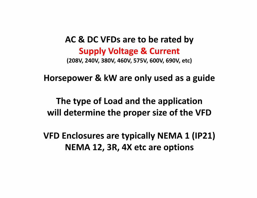
AC & DC VFDs are to be rated bySupply Voltage & Current
(208V, 240V, 380V, 460V, 575V, 600V, 690V, etc)
Horsepower & kW are only used as a guide
The type of Load and the applicationwill determine the proper size of the VFD
VFD Enclosures are typically NEMA 1 (IP21)NEMA 12, 3R, 4X etc are options
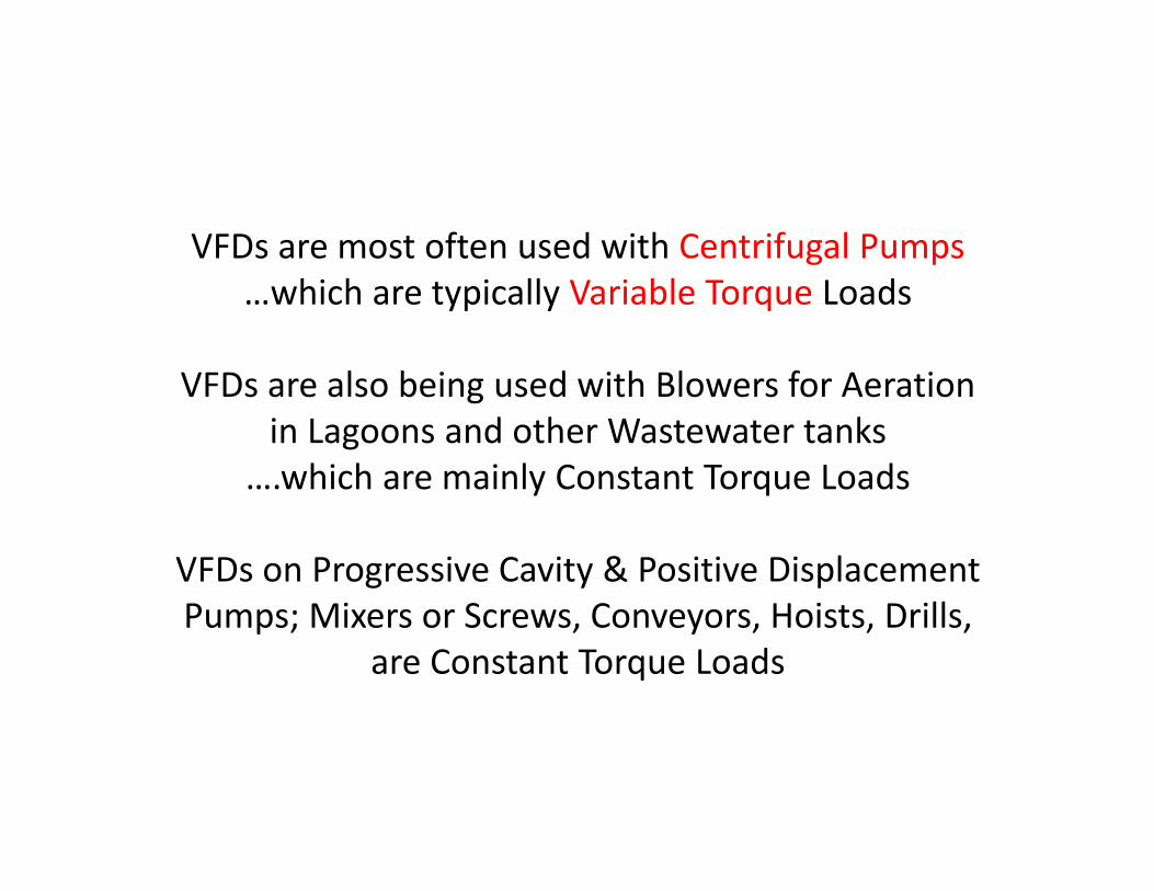
VFDs are most often used with Centrifugal Pumps…which are typically Variable Torque Loads
VFDs are also being used with Blowers for Aeration in Lagoons and other Wastewater tanks
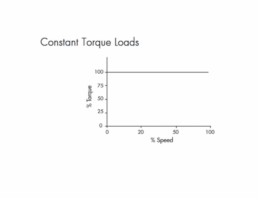
….which are mainly Constant Torque Loads
VFDs on Progressive Cavity & Positive Displacement Pumps; Mixers or Screws, Conveyors, Hoists, Drills,
are Constant Torque Loads
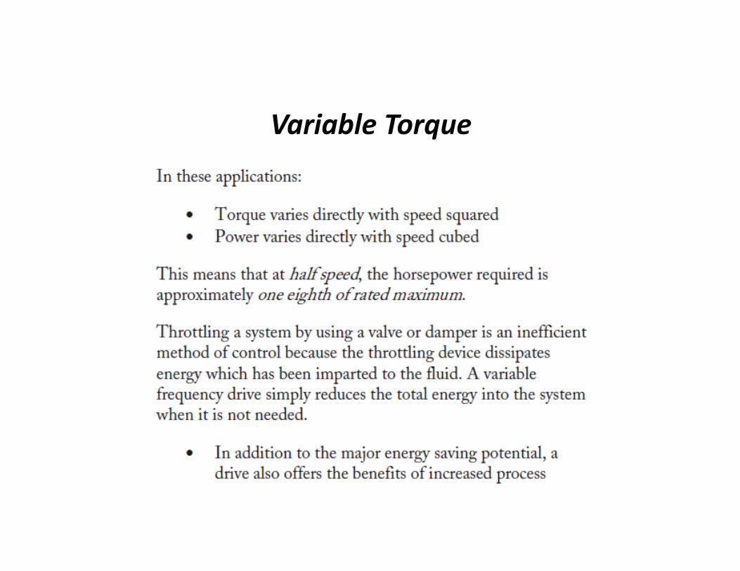
Variable Torque
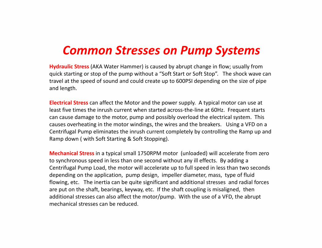
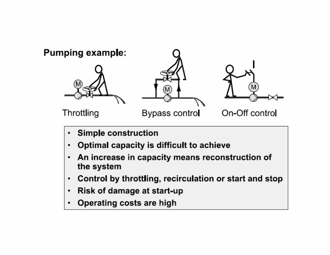
Hydraulic Stress (AKA Water Hammer) is caused by abrupt change in flow; usually from quick starting or stop of the pump without a “Soft Start or Soft Stop”. The shock wave can travel at the speed of sound and could create up to 600PSI depending on the size of pipe and length.
Electrical Stress can affect the Motor and the power supply. A typical motor can use at least five times the inrush current when started across‐the‐line at 60Hz. Frequent starts can cause damage to the motor, pump and possibly overload the electrical system. This causes overheating in the motor windings, the wires and the breakers. Using a VFD on a Centrifugal Pump eliminates the inrush current completely by controlling the Ramp up and Ramp down ( with Soft Starting & Soft Stopping).
Mechanical Stress in a typical small 1750RPM motor (unloaded) will accelerate from zero to synchronous speed in less than one second without any ill effects. By adding a Centrifugal Pump Load, the motor will accelerate up to full speed in less than two seconds depending on the application, pump design, impeller diameter, mass, type of fluid flowing, etc. The inertia can be quite significant and additional stresses and radial forces are put on the shaft, bearings, keyway, etc. If the shaft coupling is misaligned, then additional stresses can also affect the motor/pump. With the use of a VFD, the abrupt mechanical stresses can be reduced.
Common Stresses on Pump Systems
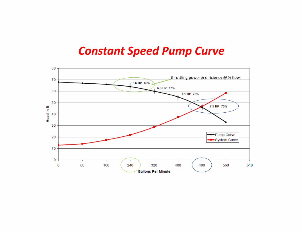
Constant Speed Pump Curve
throttling power & efficiency @ ½ flow

Variable Speed Pump Curves
power & efficiency @ ½ flow using a VFD
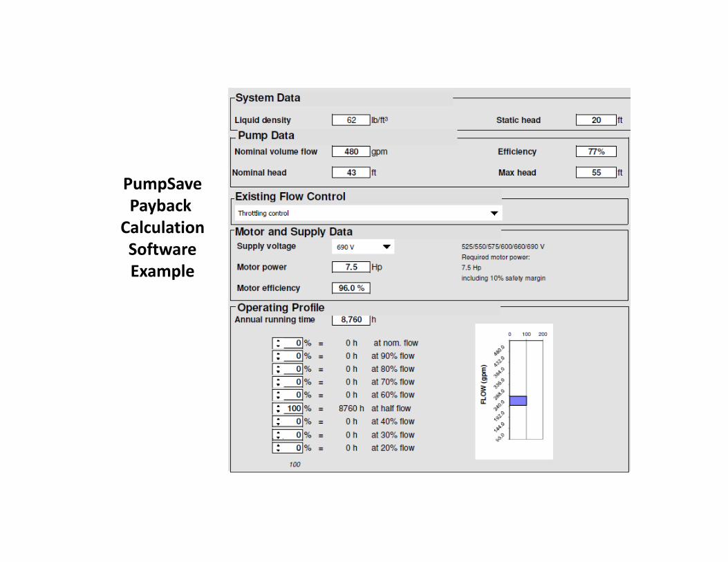
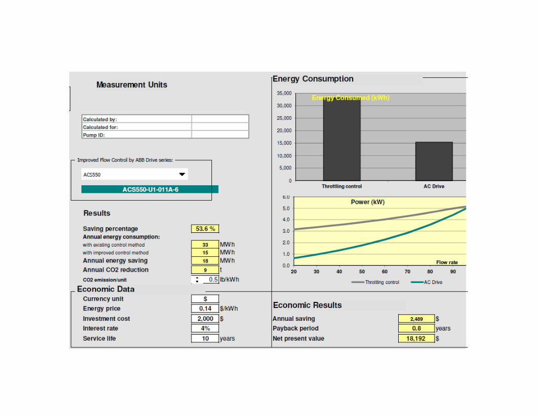
PumpSavePayback CalculationSoftwareExample

VFDDraw Backs & Solutions
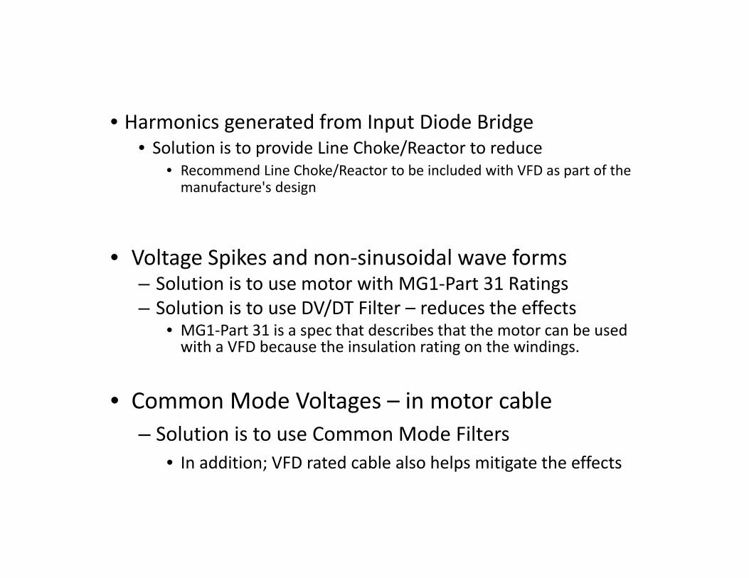
• Harmonics generated from Input Diode Bridge• Solution is to provide Line Choke/Reactor to reduce
• Recommend Line Choke/Reactor to be included with VFD as part of the manufacture's design
• Voltage Spikes and non‐sinusoidal wave forms– Solution is to use motor with MG1‐Part 31 Ratings– Solution is to use DV/DT Filter – reduces the effects
• MG1‐Part 31 is a spec that describes that the motor can be used with a VFD because the insulation rating on the windings.
• Common Mode Voltages – in motor cable– Solution is to use Common Mode Filters
• In addition; VFD rated cable also helps mitigate the effects
Adverse effects on sensitive Instrumentation• Ultrasonic Level, Magnetic Flow Meters, Generator Controllers, Solid State Circuit Breakers tripping, etc.
• Partial list of Solutions• Provide proper grounding for all equipment (high and low voltage)• Locate VFD cables away from sensitive equipment and cables• Use shielded cables for Instrumentation• Adhere to Mfg.'s installation Instructions i.e. special Grounding
• Ultimate solution – use and Ultra‐Low Harmonic VFD• Provides less than 4% Current Total Harmonic Distortion• Produces better Current Sine Wave for Motor

VFDMajor Benefits
• Reduction in speed reduces wear of pump parts• bearings, seals, other moving parts – life is extended
• Bearing wear reduces by the seventh power of speed• Slowing the pump speed reduces the requirement of maintenance
• MTBF (mean time between failure) = 20 years– Provided regular maintenance is performed
• Cleaning out dust, cooling fan replacement, etc.
• Excellent Displacement Power Factor ~ 97% – No requirement for PF Correction Capacitors
• No inrush currents – as with Direct Online Starting
• Open Loop VFD/Motor speed control• No requirement for Motor Shaft Encoder Feedback Sensor
• Process control can be optimized via 4 ‐ 20 mA Transducer/Signals• Flow, Level, Temperature & Pressure are measurements used for inputs
• Integral Diagnostics and Fault Protections– Micro‐processors – monitors and protects VFD and Motor
• Protections ‐ Short Circuit, Ground Fault, Overload, Motor Stall, Underload, Over Voltage, Under Voltage, Phase Loss, Over Temperature, etc.
• Serial Communications & PLC Functions Available– EtherNet, Modbus, DeviceNet, Profibus, etc.
• Multiple I/O – Analogue and Digital – fully programmable
• Variable Speed – Over & Under Base Speed • If Motor is lightly loaded, the VFD can output above 60Hz (within reason)
• Over Speeding Pump ‐ Provides additional flows (if motor is under‐loaded & can handle higher speed) to help occasional peak conditions without requiring a different pump.
• Pressures and Motor Current draw to be monitored for protection.
– VFD can output below 60Hz (system curve dependant)• Reducing Speed of Pump ‐ Provides additional process, pressure and flow controls.
• Considerable energy savings with operating Rotodynamic (AKA) Centrifugal Pumps at reduced speeds… Affinity Laws.
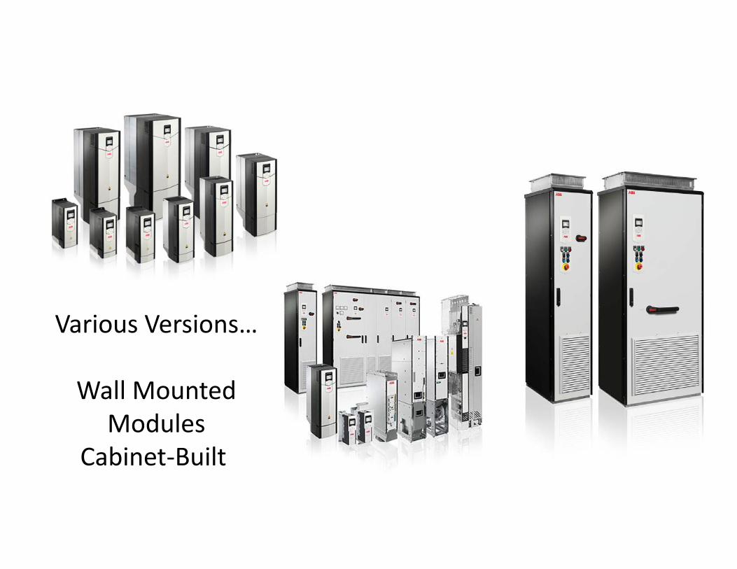
Various Versions…
Wall MountedModules
Cabinet‐Built
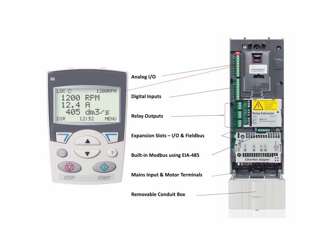
Analog I/O
Digital Inputs
Relay Outputs
Expansion Slots – I/O & Fieldbus
Built‐in Modbus using EIA‐485
Mains Input & Motor Terminals
Removable Conduit Box
EtherNet Adapter
Relay Extension

Thank you
Questions?


