28
LIBERTé

LIBERTé

✓
3
Please call our Technical help line:(weekdays 9am-5pm)
(standard call rate charge applies)
Page 3 IndexPage 4 Welcome to SWIFTY power assisted cyclingPage 5 Schematic of your new bikePage 6 Unpacking your new bikePage 6-7 Setting -up your e-bikePage 8 Pre-ride checks / Getting startedPage 9 Understanding your ControllerPage 10 Understanding the BatteryPage 11 Understanding the GearsPage 12 Charging the BatteryPage 13-15 Adjusting the Rear DerailleurPage 16-17 Adjusting the Mechanical Disc BrakesPage 18 Inspecting & Maintaining the Wheels Page 19 Changing/replacing the tyre/innertubePage 20 Warning! & Torque Setting Chart Page 21-22 Routine MaintenancePage 23 Safety on your bikePage 24 Safety on the roadsPage 25 Simple troubleshootingPage 26 WarrantyPage 27 Notes

4
✓
Welcome to SWIFTY power assisted cyclingEssentially your new electric bike works exactly the same as a standard bike, peddling to propel the bike forward using the gears to suit the terrain and the speed you want to go....only now you have an electric power assistance at your �ngertips to take the strain out of those tough uphill struggles and making cycling a much more pleasant experience.
Simply explained this is how your electric bike works. 1. Switch the battery to ON, with the switch on the side left-hand side of the battery. 2. Switch the power on by pressing the ‘POWER’ button on your controller on the handlebars. 3. As you begin to pedal a sensor will read the level of e�ort needed to turn the wheels of your bike.4. After one complete turn of the pedal the electric motor kicks in making pedaling much easier.5. There are 3 setting on your controller on the handlebar, allowing you to set the level of assistance you require. For example: Riding up a hill you’ll probably use ‘level 3’, mode.6. Change the level of assistance you need, any time and as often as you wish.7. The motor works to assist pedalling, stop pedalling and the motor stops too.8. Applying the brakes cuts the motor9. You can also choose to switch the assist OFF and ON on the controller at any point in your journey. This helps to save battery power if its not needed. The more you use the assist, the more power it uses, each rider is di�erent so �gures can vary considerably with di�erent rider weight and the terrain you ride. Generally with normal use, you should be able to obtain around 20 miles, before you need to re-charge your battery.
We Recommend that you get used to your new e.bike and the level of assist you place on it, you’ll soon be able to work out how long a journey you can make and safely return under assist. You can of course ride as you would a normal bike if the charge runs out.
The A-weighted emission sound pressure level at the Rider’s ears is less than 70dB (A).
Firstly may we congratulate you on purchasing your new electric power assisted e.bike.
Please take time to read your manual. We have tried to write it in a way that is simple and easy to follow, whilst explaining how your bike works and how it is maintained.At any point if you feel you need help we have a tehnical helpline for support.
Please call our Technical help line:(weekdays 9am-5pm)
(standard call rate charge applies)
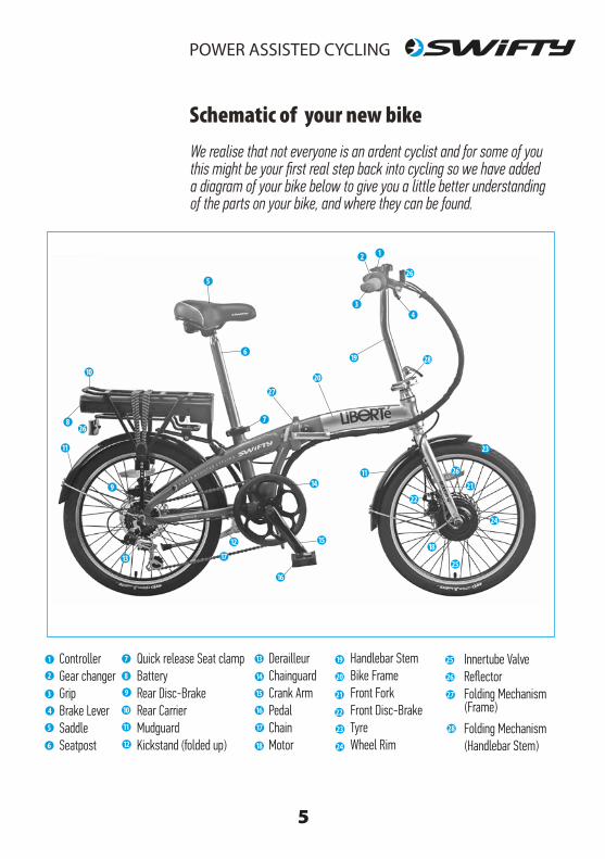
Schematic of your new bikeWe realise that not everyone is an ardent cyclist and for some of you this might be your first real step back into cycling so we have added a diagram of your bike below to give you a little better understanding of the parts on your bike, and where they can be found.
ControllerGear changerGripBrake LeverSaddleSeatpost
Innertube ValveReflectorFolding Mechanism
Folding Mechanism
DerailleurChainguardCrank ArmPedalChainMotor
Quick release Seat clampBatteryRear Disc-BrakeRear CarrierMudguardKickstand (folded up)
Handlebar StemBike FrameFront ForkFront Disc-BrakeTyreWheel Rim
1
2
3
4
5
6
7
8
9
10
11
12
13
14
15
16
17
18
19
20
21
22
23
24
25
26
1
5
6
78
10
11
1114
1518
19
23
26
26
26
27
27
28
28
17
16
20
21
24
25
2
3
(Frame)
(Handlebar Stem)
5
13
Essentially your new electric bike works exactly the same as a standard bike, peddling to propel the bike forward using the gears to suit the terrain and the speed you want to go....only now you have an electric power assistance at your �ngertips to take the strain out of those tough uphill struggles and making cycling a much more pleasant experience.
Simply explained this is how your electric bike works. 1. Switch the battery to ON, with the switch on the side left-hand side of the battery. 2. Switch the power on by pressing the ‘POWER’ button on your controller on the handlebars. 3. As you begin to pedal a sensor will read the level of e�ort needed to turn the wheels of your bike.4. After one complete turn of the pedal the electric motor kicks in making pedaling much easier.5. There are 3 setting on your controller on the handlebar, allowing you to set the level of assistance you require. For example: Riding up a hill you’ll probably use ‘level 3’, mode.6. Change the level of assistance you need, any time and as often as you wish.7. The motor works to assist pedalling, stop pedalling and the motor stops too.8. Applying the brakes cuts the motor9. You can also choose to switch the assist OFF and ON on the controller at any point in your journey. This helps to save battery power if its not needed. The more you use the assist, the more power it uses, each rider is di�erent so �gures can vary considerably with di�erent rider weight and the terrain you ride. Generally with normal use, you should be able to obtain around 20 miles, before you need to re-charge your battery.
We Recommend that you get used to your new e.bike and the level of assist you place on it, you’ll soon be able to work out how long a journey you can make and safely return under assist. You can of course ride as you would a normal bike if the charge runs out.
The A-weighted emission sound pressure level at the Rider’s ears is less than 70dB (A).
4
9
12
22

Unfold the frame until the 2 parts of the frame are inline, close lever pushing towards the frame, this should feel quite tight, then push the safety locking clip down so that it slots into the hole in the top edge of the lever preventing the lever from accidental opening during use.To unlock and fold the frame simply reverse these steps.
✓
6
Unpacking your new bikeYour bike comes 85% assembled in the Carton, you only need to Fit the pedals, unfold the Frame the handlebar assembly and insert the saddle assembly.
1. Before you begin to unpack your e.bike we recommend you get another person to assist you as it s much easier with 2 persons to lift out of the box.
2. Remove all the packing materials used to protect the bike and dispose of it later in a responsible manner.
3. Once you have unpacked the bike it is a good idea to check to make sure there has not been any damage in transit. ( If you �nd anything missing or damaged, contact the Technical helpline below).
Having unpacked your bike follow the simple steps of �tting the pedals, handlebar and saddle assemblies by following the instructions on the next page.
Handy Tip: Its a good idea to rest your bike on the bike stand which is attached to the rear chainstay, this makes it much easier and leave your hands free
to make adjustments to other parts.
Fitting the PedalsMatch the left pedal to the left crank, and the right pedal to the right crank.Left Pedal - Tightens Anti-clockwiseRight Pedal - Tightens ClockwiseTighten the pedal as far as possible with your �ngers. Use the tool provided to tighten them �rmly
Unfold the Bike FrameSetting up your e.bike
NOTE: Should you ever need to replace the pedals remember the right pedal tightens clockwise and the left pedal anti-clockwise.
Quick Release frame mechanism
Unpacking the Carton
Stamped Crank ends ‘L’ and ‘R’
AB
B
A

7
The Saddle and Seatpost are already �tted together.
1. Slide the seatpost into the seatbube and close the tension lever on the quick release clamp to lock your seat in place.
2. Adjust the saddle height to suit you by releasing the clamp and tightening when at the correct height ,( see below)
4. If the clamp does not tighten enough to hold the saddle in position simply lift the tension lever to release and turn a quater turn of the adjustment nut clockwise and close the tension lever. Repeat as necessarry.
Fitting the Saddle
Locking the Handlebar/StemThe handlebars and stem come folded down and strapped to the side of your bike, cut the ties and lift the handlebar assembly into upright position, Lock in position using the quick release mechanism adjusting in the same manner as the quick release on the seatpost. Before riding always check that the quick release clamp is tight.
Brakes on the HandlebarAs you sit on your bike and take hold of tha handlebar it is important to know that the right-hand brake lever controls the FRONT brake and the left-hand lever the REAR brake.
NOTE:
NOTE:
Adjusting seat calmp
Fold up the Stem and lock inplacewith the quick-release clamp
A
MinimumInsertionMark
Open Closed
A
Seatpost
Clamp
1. Turn crank to place it in it’s lowest position.2. Place heel on pedal with foot parallel to the ground.3. Position saddle so that tos of other foot can touch the ground. Saddle should also be parallel to the ground.4. Tighten seat post bolt.
Recommended torque is 150 in/lbs
The Seat post must be inserted at least to the minimum insertion mark stamped on the lower part of the seat post.If no minimum insertion mark can be found , make sure at least 3 inches of th post is inside the bicycle frame tube.
Disc Brakes are powerful brakes and can stop the bicycle very quickly. We recommend you become familiar with thier stopping power by initially applying at lower speeds to avoid any accidents.

✓
8
Complete these checks before every ride
1. Check to make sure all nuts/fastenings are tight2. Check that your tyres are in�ated su�ciently (see tyre wall )3. Check that the brakes are working correctly. (These are set by the factory and should not require adjusting). 4. Check your battery for charge ( see controller) (Note: Your new SWIFTY battery is supplied with a partial charge)
Pre-Ride Checks
1. Switch the battery on with the switch on the left-hand side of your battery2. Press POWER button on the Controller on your handlebars 3. ‘MODE’ is set on ‘1’ - This is a default setting. THAT‘S IT........You’re ready to go.
4. To start , simply begin to pedal. Once the crank is turning you will feel the motor kick-in and the electric system begin to assist you. 5. You have 3 levels of assist and its a good idea to try all levels to give you a feel of the e�ect this has on your riding. 6. Remember, stopping pedalling or braking cuts the motor assist, so you can always feel safely in total control.
Getting Started
Applying the brakes activates the brake sensor which cuts the power to the motor.
Applying the brakes activates the brake sensor whichcuts the power to the motor.
Press the power button
Switch battery ON
Check battery for charge
A
A
B
B
IMPORTANT NOTE: The total permissible weight of the Rider + Luggage is 125Kg

9
Understanding your controller
Press to switch ON/OFF
Press to increase assistlevel 1-3.
Press to reduce assistlevel 3-1. handlebar control unit
Your Module Controller has several functions and is relatively simple and easy to operate, we have listed the buttons and their various functions.
Holding down this button activates the ‘WALK MODE’ which engages the motor from a standing start upto 5 mph which is a great way to set of from tra�c lights, or when walking with your bike.
1. ON/OFF button - Switch on after you have switched battery switch to ‘ON’ 2. Lever buttons - 1- 3, easy selection levels of assistance3. Battery Indicator lights - These are red and go down as you use the power.4. As you ride up a hill the power indicator drops down showing increased resistance levels, but once back to level ground the indicator lights will return to a more accurate position of available power levels. 5. This bike has a 6km walking mode function, which allows you to push your bike e�ortlessly over steep ridges or hills. You can activate this function by holding down the minus button for 3 seconds.
Battery Power indicator
Light SensorAuto - controls brightness of LED lights
MODElevelcontrolbuttons
MODElevelindicator
ON/OFFbutton

C
A✓
10
1. Security
1. You are supplied with 2 keys to secure your battery to your bike. It is advisable to seperate the keys as they CANNOT BE REPLACED IF LOST. 2. The key secures your battery to the bike and by unlocking, the battery can be removed by sliding towards you, sideways out from the frame.3. To replace simply reverse the procedure.
2. Battery operation
Switching ON/OFF is by way of a switch on the rear left-hand side, remember to swith OFF when not in use as this may drain the battery. To check the power level of the battery simply press the Indicator Button and check the light display. Please Note: This can only be done with the power switched on. To charge your battery connect the charger with the lead supplied by removing the rubber cover and inserting the pin connector, plug into the main and then switch on the power.
3. Battery Charger
1. NOTE: Only charge your battery with the Charger supplied with your SWIFTY bike. The charger is set to 220/240V. Never use 110v setting. 2. Avoid dropping the Charger as this may damage the sensitive electronics within the casing. 3. You can leave the battery charging, it will stop charging by itself when it has reached full charge, but it is not recommended to leave charging for any considerable time over what is required.
Understanding your battery
A
BC
D
Battery lock
Battery power ON/OFF switch
Once unlocked the battery can be withdrawn. It is a tight �t so will require a slight tug.
Press this button to show batterycharge level, the battery needs to be switched ‘ON’ to do this.
The Battery charging point can be located on the rear od the batteryas shown so can be charged whenON or OFF the bike.
D
11
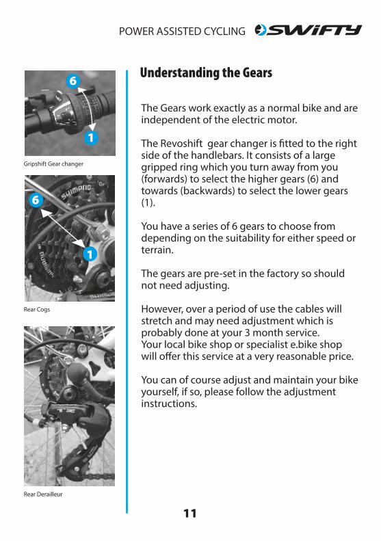
The Gears work exactly as a normal bike and are independent of the electric motor.
The Revoshift gear changer is �tted to the right side of the handlebars. It consists of a large gripped ring which you turn away from you (forwards) to select the higher gears (6) and towards (backwards) to select the lower gears (1).
You have a series of 6 gears to choose from depending on the suitability for either speed orterrain.
The gears are pre-set in the factory so should not need adjusting.
However, over a period of use the cables will stretch and may need adjustment which is probably done at your 3 month service.Your local bike shop or specialist e.bike shop will o�er this service at a very reasonable price.
You can of course adjust and maintain your bike yourself, if so, please follow the adjustment instructions.
Understanding the Gears
Gripshift Gear changer
Rear Cogs
Rear Derailleur
6
6
6
1
1
✓
12
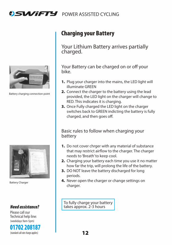
Your Lithium Battery arrives partially charged.
Your Battery can be charged on or o� your bike.
1. Plug your charger into the mains, the LED light will illuminate GREEN2. Connect the charger to the battery using the lead provided, the LED light on the charger will change to RED. This indicates it is charging.3. Once Fully charged the LED light on the charger switches back to GREEN indicting the battery is fully charged, and then goes o�.
Basic rules to follow when charging your battery
1. Do not cover chrger with any material of substance that may restrict air�ow to the charger. The charger needs to ‘Breath’ to keep cool. 2. Charging your battery each time you use it no matter how far the trip, will prolong the life of the battery. 3. DO NOT leave the battery discharged for long periods. 4. Never open the charger or change settings on charger.
Charging your Battery
To fully charge your battery takes approx. 2-3 hours
Battery Charger
Battery charging connection point
Adjusting the Rear Derailleur
13
Step1
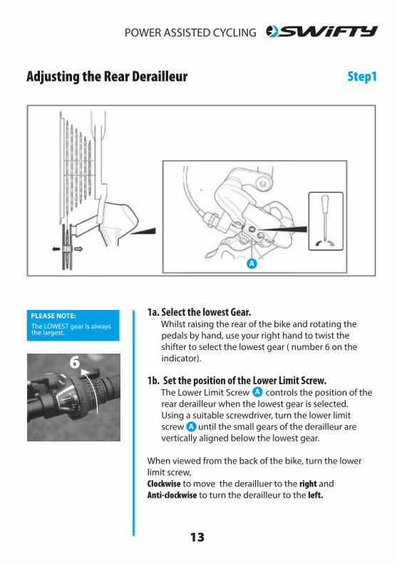
PLEASE NOTE: The LOWEST gear is alwaysthe largest.
1a. Select the lowest Gear. Whilst raising the rear of the bike and rotating the pedals by hand, use your right hand to twist the shifter to select the lowest gear ( number 6 on the indicator). 1b. Set the position of the Lower Limit Screw. The Lower Limit Screw controls the position of the rear derailleur when the lowest gear is selected. Using a suitable screwdriver, turn the lower limit screw until the small gears of the derailleur are vertically aligned below the lowest gear.
When viewed from the back of the bike, turn the lower limit screw, Clockwise to move the derailluer to the right and Anti-clockwise to turn the derailleur to the left.
6
A
A
A

✓
14
Adjusting the Rear Derailleur Step2
PLEASE NOTE: The HIGHEST gear is alwaysthe smallest.
2a. Select the Highest Gear. Whilst raising the rear of the bike and rotating the pedals by hand, use your right hand to twist the shifter to select the highest gear ( number 1 on the indicator). 1b. Set the position of the Lower Limit Screw. The Lower Limit Screw controls the position of the rear derailleur when the highest gear is selected. Using a suitable screwdriver, turn the lower limit screw until the small gears of the derailleur are vertically aligned below the highest gear.
When viewed from the back of the bike, turn the lower limit screw, Clockwise to move the derailluer to the left and Anti-clockwise to turn the derailleur to the right.
1
B
B
B

15
Rear Derailleur
Adjusting the Rear Derailleur Step3
PLEASE NOTE: The LOWEST gear is alwaysthe largest.
3a. Check the Gear Change Whilst raising the rear of the bike and rotating the pedals by hand, use your right hand to twist the shifter to change from the highest (smallest) to Lowest ( largest) gear one at a time. The gears should change quickly without any grinding noises.
If they do not operated correctly, carry out step 3b 3b. Check the Cable Tension Gears change correctly between Lowest to Highest but not between lowest to highest gears, the cable tension should be increased.
Rotate the barrel adjuster a quater turn anti-clockwise
Check the Gear change by repeating step 3a.
Continue to check the gear change, increasing by a quater turn at a time until the gears operate correctly.
3a & 3b
C

✓
16
Adjusting the Mechanical Disc Brakes Disc Brakes have gained popularity due to their better braking performance and especially in bad weather or muddy conditions where they perform much better than traditional rim brakes.
B
C
EH
P
P
P
EH
Brake pads
B
E
G S
CC
Staticpad
Movingpad
1. Checking the Brake Rotor
To check the Rotor either place your bike upside down or place in a bike stand so that you can turn your wheel freely. Spin the wheel whilst looking down the thin edge of the rotor disk to see any lateral movement. Slight bends in the disc can be straightened with a rotor tool or an adjustable spanner by gently bending back into shape. Any major distortion would be best corrected by replacing the disc.
2. Tightening the brake cable.
Begin by turning the barrel adjuster fully in (clockwise), then loosen the cable pinch bolt , pull the cable taught and re-tighten the pinch bolt taking care not to lift the caliper lever.
3. Aligning the Caliper correctly.
Loosen the two caliper bolts allowing the Caliper body to �oat, then turn the Inner Pad Adjuster all the way in (clockwise) then back o� a 1/4 turn. Pull and hold the brake lever tight which then aligns the caliper body to the Rotor Disc. Tighten the Caliper mounting bolts and back o� the Inner pad adjuster another 1/4 turn or further until the pads are not catching.
4. Brake lever travel
Pull the lever a few times checking that the brake fully contact-ing with the brake lever is around half the travel distance. Too short and it will be di�cult to apply the brake su�ciently to long the brake engages and the lever may hit the grip before full braking is achieved, meaning you won’t stop. This can be
adjusted by turning the inner Pad Adjuster.
(�g.2) When pulling the cable through for re-tightening make sure NOT to raise the Caliper Arm as this will reduce e�ective braking
(�g.3) When replacing wheels with Disc Brakes take care to make sure that Rotor �ts cleanly between the two brake pads and is aligned properly
WARNING! Avoid contact with the Brake disc after heavy use as can generate consdierable heat to the rotor.
Lorem ipsum

P
S
17
Mechanical Break disk on rear wheel
H E
DBBF
G
S
C
A
A
B
B
C
D
E
E
F
G
H
H
P
S
Caliper to Frame bolts
Caliper Mount bolts
Rotor - Breaking Disc
Caliper Arm
Cable pinch bolt
Break Cable outer
Inner Break cable
Barrel Adjuster
PAD Adjustment bolt
Split-pin holding the
Main Disc components
Break pads
5. �nal check
Spin the wheel and check the pads are not rubbing, if not, check the Caliper mount bolts and cable pinch bolt are fully tightened. If the pads appear parallel but the pads are still rubbing loosen one of the mount bolts and move the body of the caliper out slightly, then repeat with the other mount bolt in order to keep the caliper body parallel to the rotor, re-tightening the mount bolts.
5. Brake Pad wear
Your brake pad wear will depend on the amount of riding, the terrain and the weather conditions, so it is important to check pad wear regularily. You can turn the inner pad adjuster clockwise to close the pad to disc gap but you will need to re-centre the caliper body position by repeating stage 3.
PLEASE NOTE:The Barrel Adjuster on the brake cable should not be used to close the gap on the brake pads as this will also e�ect the travel of the brake lever. The Barrel Adjuster should be used to tighten the taughtness of the brake cable.
✓
18
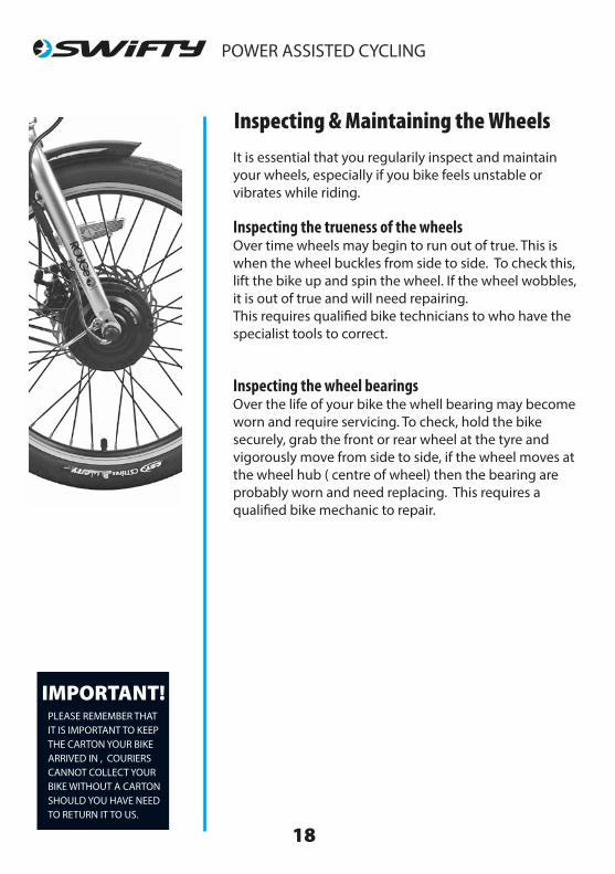
Inspecting & Maintaining the WheelsIt is essential that you regularily inspect and maintain your wheels, especially if you bike feels unstable or vibrates while riding.
Inspecting the trueness of the wheelsOver time wheels may begin to run out of true. This is when the wheel buckles from side to side. To check this, lift the bike up and spin the wheel. If the wheel wobbles, it is out of true and will need repairing.This requires quali�ed bike technicians to who have the specialist tools to correct.
Inspecting the wheel bearingsOver the life of your bike the whell bearing may become worn and require servicing. To check, hold the bike securely, grab the front or rear wheel at the tyre and vigorously move from side to side, if the wheel moves at the wheel hub ( centre of wheel) then the bearing are probably worn and need replacing. This requires a quali�ed bike mechanic to repair.
19
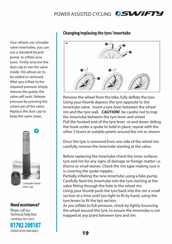
Changing/replacing the tyre/ innertube
Remove the wheel from the bike, fully de�ate the tyre. Using your thumb depress the tyre opposite to the innertube valve. Insert a tyre lever between the wheel rim and the tyre wall. CAUTION! be careful not to trap the innertube between the tyre lever and wheel. Pull the hooked end of the tyre lever ut and down sliding the hook under a spoke to hold in place, repeat with the other 2 levers at suitable points around the rim as shown.
Once the tyre is removed from one side of the wheel rim carefully remove the innertube starting at the valve.
Before replacing the innertube check the inner surfaces tyre and rim for any signs of damage or foreign matter i.e. thorns or small stones. Check the rim tape making sure it is covering the spoke nipples.Partially in�ating the new innertube using a bike pump.Carefully feed the innertube into the tyre starting at the valve �tting through the hole in the wheel rim.Using your thumb push the tyre back into the rim a small section at a time until too tight to �t by hand, using the tyre levers to �t the last section.As you in�ate to full pressure, check by lightly bouncing the wheel around the tyre, to ensure the innertube is not trapped at any point between tyre and rim.
Schrader Valvewith Cap.
Your wheels use schrader valve innertubes, you can use a standard bicycle pump to in�ate your tyres. Firstly unscrew the dust cap to see the valve inside, this allows air to be added or removed. After you in�ate to the required pressure simply remove the pump, the valve self seals. Release pressure by pressing the centre pin of the valve. Replace the dust cap to keep the valve clean.
P

✓
24
Safety on the Roads
When you join the road system you must obey the Tra�c Laws like the rest of the vehicles travelling along that road.
Always excercise maximum caution on busy roads especially around large vehicles as you are not always seen.
Be aware that in wet conditions your brakes stopping power ( and those of other road users) is greatly reduced.
When riding at night make sure your bike conforms to the lighting laws as cyclists are often hard to spot for drivers and pedestrian, especially in the winter months where hours of daylight are reduced.Your trip out may be in daylight...your trip back may not.
Extra caution should be taken when braking in wet weather, where one should allow for increased braking distances.
Keeping your e.bike well maintained, wearing the right clothing, and following some common sense rules will reward you with many hours of fun and enjoyment for many years to come....
....Happy Cycling.

25
Should you ever need to remove or replace your pedals it is importantto know that left-hand pedal screws in ANTI-CLOCKWISE and the right-hand pedal screws in CLOCKWISE. Pedals are normally stamped on the ends of the axle of the pedal as in the photo, L and R.
Simple Troubleshooting
In reality there are not many things that can go wrong with an electric bicycle so generally speaking any problems you may have, should be easy to resolve.
If you make the checks outlined above and your electric bike is still not working then please call our technical helpline for assistance.
Problem :
Power indicator on the Controllerdoes not light up
Power indicator on the Controller lights up but the motor doesn’t start.
The Battery is showing no charge
My charger is not charging the battery
Make these checks :
Has the battery been switched on?Does the battery have a charge?
Check that all the cables are connected.Check that the sensor and sensor disc are not damaged
check that your battery is switched on before you press the charge indicator button.
Check the fuse in the charger plug.Check that the cabled are connected properly.

26
Subject to the following, Amazon EU SARL warrants that the goods will correspond with their speci�cation at the time of purchase and will be free from defects in material and workmanship.Amazon EU SARL o�ers a 2 year warranty on the frame from any problems relating to manufacturer workmanship or arising from material defects including breakages or cracking caused whilst riding ( other than rider misuse).
Amazon EU SARL o�ers 12 months warranty on the battery and motor for any problems relating to manufacturers workmanship or arising from material defects. The warranty does not cover misuse or failure to follow the manufacturer’s operational instructions correctly.All other components are guaranteed for 1 year for problems related to manufacturer workmanship or arising from material defects with the exception of consumable components for example brake blocks, pads, grips, tyres and tubes.
Amazon EU SARL o�ers this warranty to the original purchaser of the product. This warranty is not transferable to a third party.
Warranty
PLEASE NOTE: Any �gures quoted regarding battery performance or distances which can be obtained per single charge are based on standrard test conditions. Diverse terrain and rider weight will of course produce varying results from those stated.

27
Notes

Please Note:This bike is built to comply with the required standards.
EPAC according to EN 15194 and EN 14764.

✓
20
WARNING!We would draw your attention the e�ects of the intensive use of this bike and recommend periodic inspections of the frame, fork, suspension joints (if any), and composite components (if any).
As with all mechanical components, EPAC is subject to wear and high stresses. Di�erent materials and components may react to wear or stress fatigue in di�erent ways.If the design life of a component has been exceeded, it may suddenly fail, possibly causing injuries to the rider. Any Form of Crack, or change of colouring in high stressed areas indicate that the life of the component has been reached and it should be replaced.
Also in the event of impact damage you must have the bike checked over by a quali�ed Bike Mechanic as damage cannot always be visable.
Part Torque (Nm)Front Wheel Nuts 22-25 NmRear Wheel Nuts 25-29 NmHandlebar Clamp Nuts 16-18 NmStem Bolt 17-19 NmSeat Clamp Bolt or Nuts 16-18 NmSeat Post Clamp Allen bolt 8-10 NmBrake Cable Pinch Bolt 6-8 NmCrank Bolt or Nut 45 NmPedals 40 NmQuick Release Tight Enough to secure (150-200N)V-Brake Brake Blocks 8-10 Nm
A helpfull List of recommended tightening levels of some of the main bike fastenings.

21
Routine MaintenanceBefore and after each ride
Check to ensure it is safe to use and operating properly.
1. Check all �xtures and �tting are tight.2. Check tyres are in�ated correctly between 25-35psi. 3. Check that your brakes are operating correctly.4. Check your gears work correctly.5. Remember if your journey means you will arrive back in the evening that you have working lights.6. Check your bike is clean.
Every Month
You should make these checks once a month or after any long rides
1. Check the bike is clean and suitably lubricated
Thoroughly clean and de-grease your bike. Ensure the Chain, Gears, Rear derailleur are adequately lubricated using a suitable lubricant.( Recommend 30SAE lubricating oil)Clean o� any excess lubricant as this attracts dirt and may prevent the bike from operating correctly.
2. Check the all parts of the bike are securely �tted
Its essential for your safety that all securing nuts and bolts are fully tightened. Pat particular attention to Pedals, wheel nuts, seat post and saddle, and the stem bolts.
Whilst holding the bike with one hand vigorously shake the crank arms and wheels to check for any sideways movement which would indicate worn bearings.(This would require quali�ed bike technician help.)
PLEASE NOTE: If you do not feel that you can complete the maintenance of your bike, please take it to your local bicycle workshop where they will be able to assist you.
General
1. Wipe your bike over with adry cloth, or neutral detergent.
2. Use lubrication oil for metal parts. i.e. chain, axles.
3. Wipe down Plastics and paint coated parts with quality cloth. 4. Increase the frequency of lubricating oil at wet orhummid areas ( Recommend 30SAE lubricating oil)
The Motor should not be lubricated

✓
22
IMPORTANT!PLEASE REMEMBER THATIT IS IMPORTANT TO USEAPPROPRIATE SPARES, i.e. TYRES, INNERTUBES, BRAKE PADS, WHICH ARESUITABLE FOR YOUR BIKE.
A CYCLE SPECIALIST WILLBE ABLE TO ADVISE YOUTO ENSURE YOU FIT ONLYSUITABLE PARTS.THIS ALSO APPLIES TOANY ACCESSORIES YOU MAY WISH TO ADD TOYOUR BIKE.FITTING COMPONENTSUNSUITABLE FOR YOURBIKE MAY VOID YOUR WARRANTY.
Every Month (cont.)
Every 3 Months
3. Check that the tyres are in good condition
Check the outside of each tyre for signs of damage, cuts, deformations, excessive wear or bald spots. If your tyres some any of these signs of damage, it must be replaced immediately. Do not attempt to ride the bike with damaged tyres.
4. Check the wheel spokes are tightCheck the tightness of the spokes. This can be done by gently squeezing two spoke together at the same time. If you notice any movement, the spokes may need tightening. Repairing wheels and tightening spokes requires specialist tools and best undertaken by a quali�ed bike mechanic. Contact your local bike Dealer.
5. 3 Month InspectionWe recommend after 3 months you complete a full service on your bike to keep it in excellent working order. The cables will stretch requiring adjustment to brakes and gear cables. The simplest way is to take into your local bike shop where a quali�ed bike mechanic will give your bike a quick checkover and make the necessary adjustments. Giving you peace of mind.
When stored and not in use remove the battery and store in a cool, dry place, charging periodically as the battery will discharge over time of non use. Failure to do this will result in the battery falling into a dormant state render-ing the battery unrepairable.
23
Safety on your bike
This bike is designed for general use and not designed to be used o�-road or for sporting activity. Incorrect use could potentially cause serious injury.
Getting used to your new electric bike is always a wise step to take.
It therefore makes common sense, for your �rst few rides, to choose somewhere away from major roads with tra�c, people and obstacle whilst you become familiar with the controls and gain con�dence in how your electro- assist works.
It is now compulsary to always wear a Helmet when riding a bike but there are also other items of protection you might consider ....not forget-ting your eyes.
Most serious cycling accidents involve head injuries, some which may have been avoided had the rider worn a correct helmet.Check your helmet meets the correct classi�cation standards appropriate for the riding you’re doing. ( Check with your local Cycle specialist)
Please make sure you wear clothing and footwear appropriate for riding, loose clothing and loose shoe laces can cause accidents if caught in moving parts on your bike.
Remember this is the UK, and the weather is changable, either wear or pack waterproof clothing.


