2028-18 Joint ICTP/IAEA Workshop on Atomic and Molecular Data for Fusion Detlev REITER 20 - 30 April 2009 Forschungzentrum Juelich, Institute for Energy Research, Plasma Physics 52425 Juelich GERMANY WHAT - Can we tend the fire?
Transcript
2028-18
Joint ICTP/IAEA Workshop on Atomic and Molecular Data forFusion
Detlev REITER
20 - 30 April 2009
Forschungzentrum Juelich, Institute for Energy Research, Plasma Physics52425 Juelich
GERMANY
WHAT - Can we tend the fire?
Forschungszentrum Jülichin der Helmholtz-Gemeinschaft
Detlev ReiterForschungszentrum Jülich GmbH, Institut für Energieforschung-4
52425 Jülich, Germany
Can we tend the fire?
Joint ICTP-IAEA Workshop on Atomic and Molecular Data for Fusion, Trieste 20-30 April 2009
Thanks to: V. Philipps, A. Kirschner, R. Janev
Three lectures course on plasma surface interaction and edge physics
I Introduction: WHAT happens in a fusion plasma near the walls
Chemical process:CxHy….+O2+… COz + H2O+… Nuclear process:
d + t He + n
Mankind learning to tend a fire, again….
The Energy source of the sun and the stars in the universe is: Nuclear Fusion
The vision of nuclear fusion research:
A miniatur star in a solid container
The Sun: T=15 Mill. degrees in the center
p + p d, d + p He3 , He3 + He3 He4 + p + p, Reaction time 1/(np< v>fus)=tfus approx. 109 years
Fusion Reactor: T=100 Mill. degrees
d + t He + n
Much too cold !
What these lectures are NOT about:
Fusion reactor
The correct way: a magnetic bottle Here: the JET Tokamak
2 meters
Euratom - TEKES (1995)Finland (incl. Estonia)
Euratom - DCU (1996)Ireland
Euratom - ÖAW (1996)Austria
Eur - Hellenic Rep (1999)Greece (incl. Cyprus)
Euratom - IPP.CR (1999)Czech Rep.
Euratom - HAS (1999)Hungary
Euratom – MEdC (1999)Romania
Euratom – Univ. Latvia Latvia (2002)
Euratom - IPPLM (2005)Poland
Euratom - MHEST (2005)Slovenia
Euratom – CU (2007)Slovakia
Euratom – INRNE (2007)Bulgaria
Euratom – LEI (2007)Lithuania
Euratom - CEA (1958)France
Euratom – ENEA (1960)Italy (incl. Malta)
Euratom - IPP (1961)Germany
Euratom - FOM (1962)The Netherlands
Euratom - FZJ (1962)Germany
Euratom - Belgian State Belgium (1969)(incl. Luxembourg)
Euratom - RISØ (1973)Denmark
Euratom – UKAEA (1973)United Kingdom
Euratom - VR (1976)Sweden
Euratom - Conf. SuisseSwitzerland (1979)
Euratom - FZK (1982)Germany
Euratom –CIEMAT (1986)Spain
Euratom – IST (1990)Portugal
Euratom 26 Fusion AssociationsJoint construction of JET (1978)Joint construction of JET (1978)
Power exhaust steadysteady statestate heatheat loadsloads
Monoblock concept
Tw
Power exhaust transienttransient heatheat loadsloads (1)(1)
In transient events, like disruptions or ELMs, part of theplasma stored energy is deposited in very short pulsesto the walls
example: type I Elms in ITER:Wthermal (Plasma) 350 MJ
energy loss during ELM 2-6 %
Energy per ELM 20 MJ (~30 hand grenades at 150g TNT each)
deposition time 0.2 ms
deposition area 10 m2
power density 10 GW/m2
In transient events the energy must be absorbed bythe heat capacity ( inertial cooling )
T ( t) = P * ( 2 / c ) 0.5 * t 0.5
temperature power conductivity density heat capacity
t = 0.25 ms Tsmax = 6000 C Penetration depth: 0.15 mm
Sublimation threshold: 2200 C
Graphite Target will sublimate quickly
With duration of 0.2 ms and area 10 m2 the maximal energy per ELM in ITER must limited to < 1-2 % of stored energy to avoidmaterial loss by sublimation
Metals will melt leading to loss of melt layer by MHD effects in melt layer
Type I ELM operation critical for ITER
transienttransient heatheat loadsloads (2)(2)
Material Behaviour under Extreme Power LoadsBe
:ca.
150
mW
:ca.
10μ m
e- beam(120 keV)
boiling and droplet formation
melt ejection
metals graphite, CFC
homogeneousmelting
increasing energy density increasing energy density
brittle destructionsublimation
FOR METALS:SplashingFormation of dropletsFormation of dust
FOR CARBON:Above a certain power load (threshold) emission of debris occurs = BRITTLE DESTRUCTION
Effects of interaction
MELTING observed commonly in present machines
Beryllium antenna screenat JET
Tm(Be) = 1278 oC
Limiter from FTU TZM coated with 2 mm VPS Tungsten
TEXTOR: Melting of 170 mm B4C coating on copper
The TEXTOR PWI Test Facility with air locka tool (user facility) for PWI research
viewing lines for diagnosticsTEXTOR PWI Test FacilityAir locks for PWI components
< 15 cm diameter (enlargement foreseen)• external heating (up to 1800K) or cooling
(down to RT)• radial movement (+- 5 cm around LCFS)• rotatable• electrical biasing of limiters• exchange time for samples <½ day• local gas injection systems
Physical sputtering : deuterium impact on different first wall materials• Maxwellian energy distribution
shifted by the sheath potential (3 kTe): Ein ~ 6-7 kTe
• largest physical sputter yields and low threshold for Be
• small yields and large threshold for high Z materials
threshold for D impact
Be C W 3 eV 8 eV 80 eV
D B
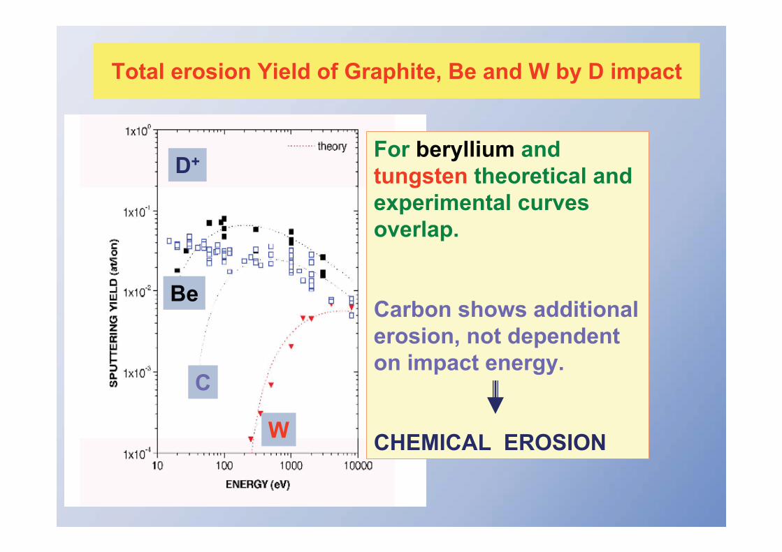
Total erosion Yield of Graphite, Be and W by D impact
For beryllium and tungsten theoretical and experimental curvesoverlap.
Carbon shows additional erosion, not dependenton impact energy.
CHEMICAL EROSIONW
C
Be
D+
III.) Chemical erosion
III.) Chemical erosion
Mechanism: formation of molecules from projectiles and solid atoms
Impinging deuterium penetrates into graphite and forms hydrocarbon molecule after thermalisation molecule “diffuses”
through porosity to surface of the solid and desorbs
D+ or D0projectile eroded hydrocarbon
graphite
CxDy
Penetration of D
Formation of CxDy
Plasma-Wall Interaction Processes
III.) Chemical erosion
Main features of chemical erosion
• Occurs only for special combinations of projectile – substrate(most important: hydrogen on graphite, oxygen on graphite)
• No (or very low) threshold energy
• Strong dependence of erosion yield Ychem on surface temperature Tsurf
• Dependence of erosion yield Ychem on hydrogen content in solid
• Synergetic effects caused by energetic ions
• Sputtered species: molecules formed from projectile and substrate atoms
Plasma-Wall Interaction Processes
III.) Chemical erosion
Fusion research: Importance of chemical erosion of carbon-based materials
Main disadvantage of carbon-based materials:
- chemical erosion due to hydrogen & its isotopes even at lowest plasma Te
- in a fusion reactor: tritium (T) as fuel erosion of CxTy molecules
re-deposition of CxTy molecules leads to formation of T-containinglayers. Amount of permitted radioactive T limited to 350g in ITER
removal of T-containing layers necessary after having reached 350g
Advantages of carbon-based materials:
- no melting even under extremely high power loads (in ITER: 10 MW/m2)
- high sublimation temperature (~3800°C)
therefore carbon-based materials are foreseen to use at areas of high power loads in ITER (divertor plates)
Plasma-Wall Interaction Processes
III.) Chemical erosion of carbon-based materials
Dependence of chemical erosion yield on surface temperature Tsurf
• Maximum erosion yield @ ~950K
• Erosion yield decreases with elevated Tsurf
400 600 800 1000 1200 14001
2
3
4
5
Met
hane
Yie
ld [%
]
Tsurf [K]
1
2
3
4
5
950 K
Plasma-Wall Interaction Processes
III.) Chemical erosion of carbon-based materials
Flux dependence of chemical erosion yield
1019 1020 1021 1022 1023 102410-3
10-2
10-1
Che
mic
al E
rosi
on Y
ield
(at/i
on)
Ion Flux (m-2s-1)
Ion Beams IPP PSI1 JT-60U outer div ToreS 2001 ToreS 2002 TEXTOR PISCES JET 2001
Chemical erosion yield decreases with increasing deuterium flux
Plasma-Wall Interaction Processes
1.E+00
1.E-05
1.E-04
1.E-03
1.E-02
1.E-01
200 400 600 800 1000Temperature [K]
Tota
l Ero
sion
Yie
ld [C
/Ho
or C
/Do ]
1.E-05
1.E-04
1.E-03
1.E-02
1.E-01
Ho on graphite
Do on a-C:H
hard
more soft
Ho on diamond films
1000
III.) Chemical erosion of carbon-based materials
Chemical erosion yield in dependence on properties of carbon material
Soft (hydrogen-rich) carbon layers suffer from an
enhanced chemical erosion
a-C:Hamorphous
hydrocarbon layer
III.) Chemical erosion of carbon-based materials
Energy and angle distribution of eroded particles
Angle distribution of chemically eroded molecules:
as for physical sputtering: good choice cosine distribution
Chemically eroded particles have Maxwell
distributed energy
(E ~ kTsurf ~ 0.05 eV @RT)
0.0 0.1 0.2 0.3 0.4 0.50
1
2
3
4 300K 2000K
E [eV]
N [a
.u.]
Plasma-Wall Interaction Processes
IV.) Radiation Enhanced Sublimation (RES)
IV.) Radiation Enhanced Sublimation (RES)
Erosion yield from beam experiments in dependence on surface temperatures
Ueda et al.
5 keV Ar+ on graphite
For carbon-based materials:
increasing erosion yield at surface temperatures larger than ~1000K
radiation enhanced sublimation
physical sputtering
Plasma-Wall Interaction Processes
IV.) Radiation Enhanced Sublimation (RES)
Mechanism of RES
• During diffusion of C interstitials to surface: probability of recombination with vacancies or stable defects ( annihilation of interstitial)
• Density of vacancies increases with increasing ion fluxflux dependence of RES
• So far RES not clearly seen in tokamak experiments (not yet clarified)
ion
C interstitial
impinging ion produces C interstitial
C interstitial diffuses to surface and sublimes
sublimated C
graphite
Plasma-Wall Interaction Processes
V.) Backscattering
V.) Backscattering
Reflection of impinging particles at the surface
in out
solid
reflected particle
incoming particle
particles incoming ofamount particles reflected ofamount R
Reflection coefficient R:
• In most cases: reflected particles are neutrals
• Reflection coefficient depends on:
- mass of projectile and target
- energy and angle of incident particles
Deposition = 1 - R
Plasma-Wall Interaction Processes
V.) Backscattering
Dependency of reflection coefficient on incident energy
1 10 100 10000.00
0.05
0.10
0.15
0.20
Ref
lect
ion
coef
ficie
nt R
Incident energy [eV]
Monte Carlo simulation (BCA): C on C, in = 60°
At low energies: BCA not valid Molecular Dynamic calculations yield R 0
Plasma-Wall Interaction Processes
V.) Backscattering
Dependency of reflection coefficient on incident angle
Monte Carlo simulation (BCA): C on C, Ein = 100 eV
in
0 20 40 60 800.0
0.2
0.4
0.6
Ref
lect
ion
coef
ficie
nt R
Incident angle in[°C]
Plasma-Wall Interaction Processes
V.) Backscattering
Energy and angle distribution of reflected particles
Plasma-Wall Interaction Processes
Reasonable assumptions:
Energy: exponential decrease for reflected particles if incoming particle energy is Maxwell-distributed
Angle: cosine distribution for reflected particles if isotropic bombardment
further important Plasma-Wall Interaction
Processes
Plasma-Wall Interaction Processes
VI.) Retention
Hydrogen retention in graphite and co-deposited layers
Four retention mechanisms have been identified:
– Build-up of a saturated surface layer during hydrogen implantation
– Chemisorption on grain boundaries and inner porosity surfaces
– Intergranular diffusion and trapping at temperatures > 1000K
– Co-deposition of hydrogen with carbon
Based on experimental data:
– Co-deposition is expected to be most important mechanism for long-term tritium retention in ITER
Licensing: in-vessel tritium inventory in ITER limited to 350g
Plasma-Wall Interaction Processes
V.) Retention
Hydrogen retention via co-deposition
physical & chemicalerosion yields: 1 - 3 %
re-deposited carbon can be re-eroded much stronger (10 - 20%)
D CxDyD
CXDyCxDy+
shadowedareas
build-up of hydrogencontaining layers
Plasma-Wall Interaction Processes
VII.) Adsorption/Desorption
Definition of the processes
Adsorption: binding of particles or molecules to a solid surface(adsorption from residual gas O2, H2O, CO …orfrom impurities segregated at surface at elevated temperatures)
physisorption: binding due to van der Waals forces (EB <~0.5eV)
chemisorption: binding via exchange/sharing of electrons (EB ~ eV)
Desorption: adsorbed species leave the surface and return into gas phase
impurity release process
Ion-induced desorption most important desorption process for fusion.
Plasma-Wall Interaction Processes
VIII.) Blistering
Trapping of gas atoms in bubbles of high pressure
Example: blistering in tungsten
Pressure in bubble too high repetitive exfoliation of micron-thick flakes
Plasma-Wall Interaction Processes
IX.) Secondary Electron Emission
Mechanisms of secondary electron emission
• reflection of electrons which impinge the surface, mostly elastic scattering
• true electron-induced secondary electron emission from the solid
• ion-induced electron emission
Why important in fusion research?
Secondary electron emission coefficient influences the the sheath potential in front of target surface exposed to
plasma (later in these lectures …)
The Impurity Transport Code ERO: see also: lecture III
radialdirection
toroidaldirection
limiter-surface
background plasma
incoming flux(D+, C4+, O5+)
reflected and eroded particles
reflected anderoded particles
deposition re-deposition
B
E C0
CD4
Cx+ CDy0,+
Detailed book-keeping of PWI processes (and local transport)
Plasma wall interaction is unavoidable and necessary for particle and energy exhaust
WHAT happens:
Low Z materials are favourable since higher concentrations can be tolerated in the plasma due to lower radiation losses but the erosion of low Z materials is stronger. A compromise between impurity release and acceptable impurity concentration must be found, which is connected by impurity transport.
Graphite has large advantages for off- normal heat loads in ELMS and disruptions, since it does not melt, but the disadvantage of high erosionand which can lead to large fuel retention by co-deposition
High Z metals have much lower erosion and show much lower hydrogen retention but metal walls can suffer from melt layer loss in off normal heat loads.
Next lecture: HOW can we make ITER work despite these issues