40
2037-15 Introduction to Optofluidics D. Cojoc 1 - 5 June 2009 TASC CNR-INFM Italy Optical manipulation of living cells in fluids
| Date post: | 15-Mar-2018 |
| Category: |
Documents |
| Upload: | truongquynh |
| View: | 219 times |
| Download: | 4 times |

2037-15
Introduction to Optofluidics
D. Cojoc
1 - 5 June 2009
TASC CNR-INFMItaly
Optical manipulation of living cells in fluids
Introduction to Optofluidics 1-5 June 2009 ICTP Trieste 1/39
������������������
� ������� ������ ������� ��
��������� ������ � �� ��� ��� �� ��������������� �� ������������� ��� ��� ���
Optical manipulation of living cells in fluids
www.tasc.infm.it/research/om/scheda.php
Dan Cojoc
������� � �������� �� � ��
Introduction to Optofluidics 1-5 June 2009 ICTP Trieste 2/39
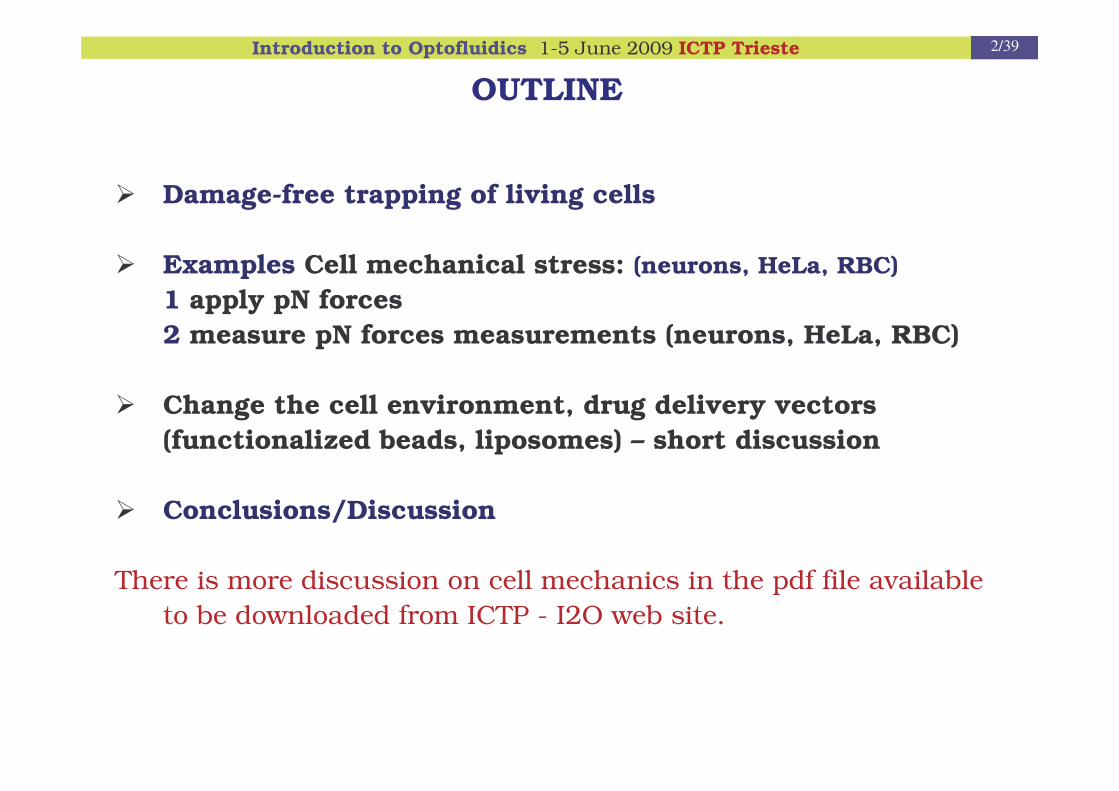
OUTLINE
� Damage-free trapping of living cells
� Examples Cell mechanical stress: (neurons, HeLa, RBC)1 apply pN forces2 measure pN forces measurements (neurons, HeLa, RBC)
� Change the cell environment, drug delivery vectors (functionalized beads, liposomes) – short discussion
� Conclusions/Discussion
There is more discussion on cell mechanics in the pdf file available to be downloaded from ICTP - I2O web site.
Introduction to Optofluidics 1-5 June 2009 ICTP Trieste 3/39
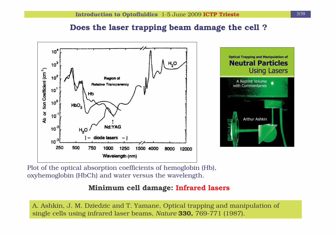
Does the laser trapping beam damage the cell ?
Minimum cell damage: Infrared lasers
Plot of the optical absorption coefficients of hemoglobin (Hb), oxyhemoglobin (HbCh) and water versus the wavelength.
A. Ashkin, J. M. Dziedzic and T. Yamane, Optical trapping and manipulation of single cells using infrared laser beams, Nature 330, 769-771 (1987).

Introduction to Optofluidics 1-5 June 2009 ICTP Trieste 4/39
E. coliCHO
Liang et al, Biophys. J. 70,1529 (1996)
The wavelength dependence of photodamage in E. coli compared to Chinese Hamster Ovarian cells.
K.C. Neuman et al, Biophys. J., 77, 2856, (1999)
Quantitative evaluation of photodamage ?

Introduction to Optofluidics 1-5 June 2009 ICTP Trieste 5/39
E. coli cells are trapped in a 3x3array and the position of two cells is then interchanged
E. Di Fabrizio, D.Cojoc et al, Microscopy Research and Technique 65, 252 (2004)
Cell array and sortingSingle cell trapping
Red Blood Cell RBC single cell
movie

Introduction to Optofluidics 1-5 June 2009 ICTP Trieste 6/39
Permanent assembly of 3D living cell microarrays
G.M. Akselrod et al Biophys J 91, 3465 (2006)
Heterotypic microarray of Swiss 3T3 mouse fibroblast and P. aeruginosa bacteria. (a) Swiss 3T3 mouse fibroblasts trapped in a 2 x 2 2D array(b,c) False-color isosurface reconstructions obtained from a confocal image of a Swiss 3T3 cell
surrounded by a ring of 16 P. aeruginosa.(d,e) Viability assay of the same heterotypic microarray showing an image obtained by exciting
propidium iodide labels with 488 nm. The lack of red fluorescence in (d) indicates viability, but after killing the cells with ethanol the fluorescence is intensely red (e).
- The array is first configured by multiple traps created with AOD and SLM
- The position of the cells is fixed permanently using a photopolymerizable hydrogelPEDGA = Polythylene glycol diacrylate

Introduction to Optofluidics 1-5 June 2009 ICTP Trieste 7/39
Input Wave(Gaussian)
Working volume:
SLMDOE
Multiple trappingby means of Diffractive Optical Elements (DOE) implemented on a Spatial Light Modulator (SLM)
3D array (cage) 3D array
movie

Introduction to Optofluidics 1-5 June 2009 ICTP Trieste 8/39
Mechanical stimulation of cells with pN forces
HeLa cell under the dynamic cage movie

Introduction to Optofluidics 1-5 June 2009 ICTP Trieste 9/39
With the optical tweezers technique one can control very precisely the
mechanical stimulation at the level of single or multiple adhesion sites
V. Emiliani et al, SPIE (2006)
Fibronectin
Integrin
Vinculin
The multi force optical tweezers is combined with an epi-fluorescence microscope to monitor vinculin recruitment as a function of applied forces.
Fibronectin coated beads are manipulated on the dorsal surface of Vin-GFP transfected HeLa cell.

Introduction to Optofluidics 1-5 June 2009 ICTP Trieste 10/39
0 2 4 6 8 1 0
In
tens
ity (a
rb u
nits
)
P o s itio n (µ m )
5pN
18pN32pN DIC
t=20’
Fluo+DIC
Trap strength
Vinculin recruitment
V. Emiliani et al, SPIE (2006)

Introduction to Optofluidics 1-5 June 2009 ICTP Trieste 11/39
Orientation of a RBC trapped by:single optical tweezers a) and four optical tweezers b)
Raman imaging
(confocal microscope + cell scanning)
Changing the orientation of a RBC for microRaman mapping the cell
D. Cojoc et al, SPIE 5930, 64, (2005)

Introduction to Optofluidics 1-5 June 2009 ICTP Trieste 12/39
Sample cell modification
Imaging 2 or other beam investigation
Sample
Sample cell
Optical tweezers+ Imaging 1
10 mm x 10 mm x 100 �m
Capillaries assample cells
Inner diameter <100 �m
50 mm
25 mm
10 um
High NALowNA
Ashkin’s sample cell
Double view imaging

Introduction to Optofluidics 1-5 June 2009 ICTP Trieste 13/39
SpatialLight
Modulator
CCD(x,y)
TL
DM
100 X1 NA
Samplecell
FI – Fiber illuminationTL – Tube lensesDM – Dichroic MirrorsL – Lenses
L L
IR TrapLaser 1064 nm
L L
TL x
y
zCCD (y,z)
40 X,0.55 NAFI
C
FI
Beamsplit
DOE –Diffractive Optical Element
Notice the different scale bar values
(y,z) lateral view
(x,y) axial view
Double view setup
movie
Piece of glass with irregular shape

Introduction to Optofluidics 1-5 June 2009 ICTP Trieste 14/39
www.biology.lsa.umich.edu/research/labs/ktosney/
Force measurementsMotivation, goal, approaches
Structural elements of the growth cone
Key determinant of axonal growth is the growth cone:"They will adopt pre-determined directions and establish connections with defined neural or extra neural elements ... without deviations or errors, as if guided by an intelligent force ." 1890 RAMON Y CAJAL
Collaboration with SISSA Trieste,Neurobiology Sector, Prof. V. Torre
Introduction to Optofluidics 1-5 June 2009 ICTP Trieste 15/39
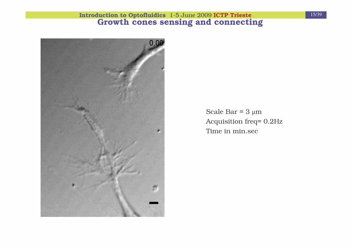
Growth cones sensing and connecting
Scale Bar = 3 �mAcquisition freq= 0.2HzTime in min.sec

Introduction to Optofluidics 1-5 June 2009 ICTP Trieste 16/39
Growth cone confocal microscopy

Introduction to Optofluidics 1-5 June 2009 ICTP Trieste 17/39
J.L. Goldberg, Genes and Dev. 17 941 (2003)
Goal measure the forces exerted by
lamellipodia and filopodia
• Calibrate the trap
• Micro-beads trapped by IR laser and positioned in front of lamellipodiaand/or filopodia
• Measure the fluctuations of the bead in the trap, due to its interaction with the motile structures, and convert them into forces.
ExperimentalApproach
D. Cojoc et al. PlosOne 2007

Introduction to Optofluidics 1-5 June 2009 ICTP Trieste 18/39
Optical Tweezers setupIncludes Optical Manipulation and Force Spectroscopy
LC-LSM: Liquid Crystal Spatial Light Modulator
CCD: Charged Coupled Device
L n: Lens 1,2,3,4,5
DM: Dichroic Mirror
QPD: Quadrant Photo-Diode
Bead position was determined by Back Focal plane (BFP) detection:
BFP of the condenser was imaged onto a QPD
F = K �xK = stiffness of the trap (springconstant)
�x = Displacement
D. Cojoc et al. PlosOne 2007

Introduction to Optofluidics 1-5 June 2009 ICTP Trieste 19/39
Features of our setup
Trap stiffness: 5-100 pN/�m
Resolution: ~10nm (1 nm)
Force range: 1-25 pN
Errors are about 10%
(Some) Problems encountered:
Stuck beads to the substrate
Trapping and calibration close to the substrate (<2 �m ) and at T=37 C
Influence of floating particles on the interference pattern
Filopodia collisions reveal lower forces than expected ? Tam-Tam !
Experimental results
Neurons obtained from dorsal root ganglia (DRG), isolated from P0-12 rats and plated on poly-L-lysine-coated glass dishes. 48 hours after incubation in 50 ng/ml of nerve growth factor (NGF).
Introduction to Optofluidics 1-5 June 2009 ICTP Trieste 20/39
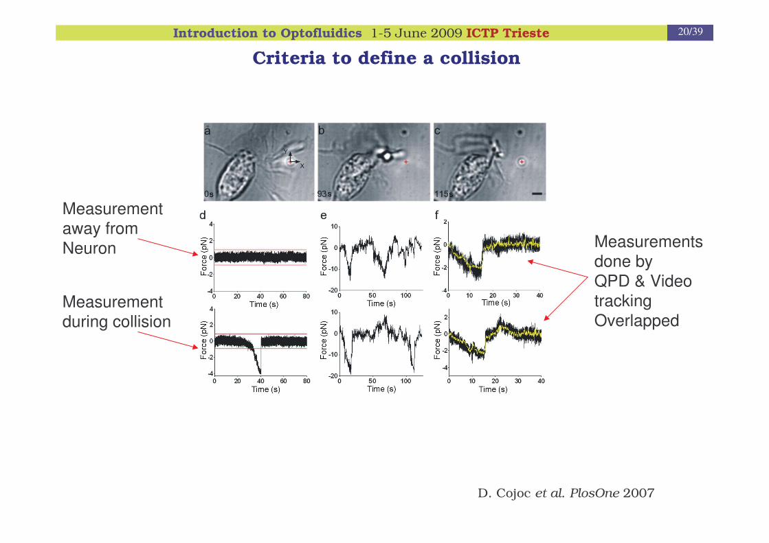
Criteria to define a collision
Measurement away from Neuron
Measurement during collision
Measurements done byQPD & Video tracking Overlapped
D. Cojoc et al. PlosOne 2007

Introduction to Optofluidics 1-5 June 2009 ICTP Trieste 21/39
Results
Filopodia 2 minutes eventFmax= 2pN
Lamellipodia 2 minutes event
Fmax measured = 20pN
> 20 pN possible
D. Cojoc et al. PlosOne 2007
Introduction to Optofluidics 1-5 June 2009 ICTP Trieste 22/39
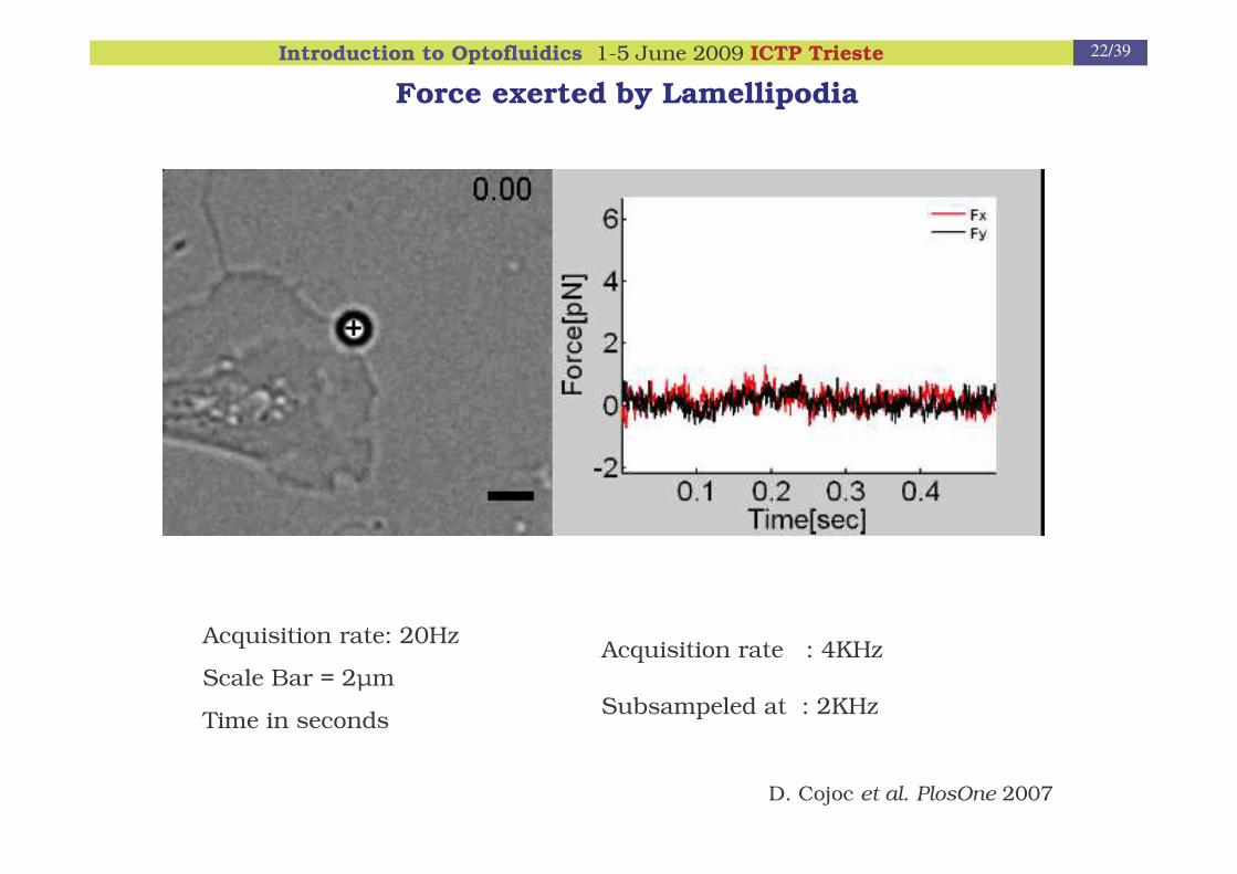
Force exerted by Lamellipodia
Acquisition rate: 20Hz
Scale Bar = 2�m
Time in seconds
Acquisition rate : 4KHz
Subsampeled at : 2KHz
D. Cojoc et al. PlosOne 2007

Introduction to Optofluidics 1-5 June 2009 ICTP Trieste 23/39
OPTICAL TRAP
SELECT AND MOVE A GIVEN CELL
REMOTELY APPLY CONTROLLED FORCESON LIVING CELLS, INTERNAL PARTS OF CELLS,AND LARGE BIOLOGICAL MOLECULES WITHOUTOPTICAL DAMAGE
MEASURE MECHANICAL PROPERTIES (FOR INSTANCE, ELASTICITY) OF DIFFERENT PARTS OF CELLS
MEASURE THE FORCES GENERATED BY SINGLEMOTOR MOLECULES IN THE PICONEWTON RANGE
USING OPTICAL SPECTROSCOPY TO MEASURE
TEMPERATURE, DNA STRUCTURE
CELL VIABILITY, INTRACELLULAR pH
OF A GIVEN SINGLE CELL

Introduction to Optofluidics 1-5 June 2009 ICTP Trieste 24/39
1) Nucleolus
2) Nucleus
3) Ribosome
4) Vesicle
5) Rough endoplasmic reticulum
6) Golgi apparatus (or "Golgi body")
7) Cytoskeleton
8) Smooth endoplasmic reticulum
9) Mitochondrion
10) Vacuole
11) Cytosol
12) Lysosome
13) Centriole
The cell
Cell mechanics skipped see the pdf file
Introduction to Optofluidics 1-5 June 2009 ICTP Trieste 25/39
� Why and how to change the environment of a cell ?
� Optically driven micro-pumps
� Optically driven vectors
functionalized beads and filled liposomes

Introduction to Optofluidics 1-5 June 2009 ICTP Trieste 26/39
Typical sample cell, cell and its environment
The environment is usually changed by micro-nano fluidics
• In general, the entire environment of the sample cell is changed
• For a localized delivery the cell position should be adapted to the micro-fluidic structure
10 mm
10 um
10 nm

Introduction to Optofluidics 1-5 June 2009 ICTP Trieste 27/39
� Why and how to change the environment of a cell ?
� Optically driven micro-pumps
� Optically driven vectors
functionalized beads and filled liposomes

Introduction to Optofluidics 1-5 June 2009 ICTP Trieste 28/39
Micro-fabricated rotors
Side view Perspective diagram
E. Higurashi et al, Appl. Phys. Lett. 64, 2209 (1994)
SiO2
Optical lithography+ RIE
P. Galajda and P. Ormos, Appl. Phys. Lett. 78, 249 (2001).
Norland resin
Two-photon lithography
22 rpm/80 mW
20 rpm /80 mW
PMMAE-Beam + X-ray lithography
3 rpm/10mW
5 µµµµm
L. Businaro et al, TASC 2005
Introduction to Optofluidics 1-5 June 2009 ICTP Trieste 29/39
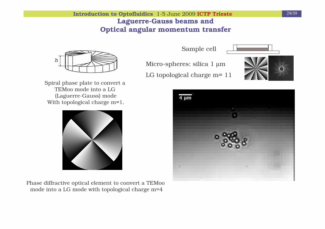
Laguerre-Gauss beams and Optical angular momentum transfer
Micro-spheres: silica 1 µm
LG topological charge m= 11
Sample cell
Spiral phase plate to convert a TEMoo mode into a LG (Laguerre-Gauss) mode
With topological charge m=1.
Phase diffractive optical element to convert a TEMoomode into a LG mode with topological charge m=4
Introduction to Optofluidics 1-5 June 2009 ICTP Trieste 30/39
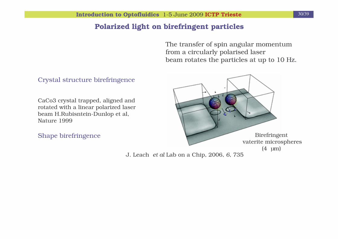
Polarized light on birefringent particles
Crystal structure birefringence
CaCo3 crystal trapped, aligned and rotated with a linear polarized laser beam H.Rubisntein-Dunlop et al, Nature 1999
Shape birefringence
J. Leach et al Lab on a Chip, 2006, 6, 735
Birefringentvaterite microspheres
(4 µm)
The transfer of spin angular momentum from a circularly polarised laser beam rotates the particles at up to 10 Hz.
Introduction to Optofluidics 1-5 June 2009 ICTP Trieste 31/39
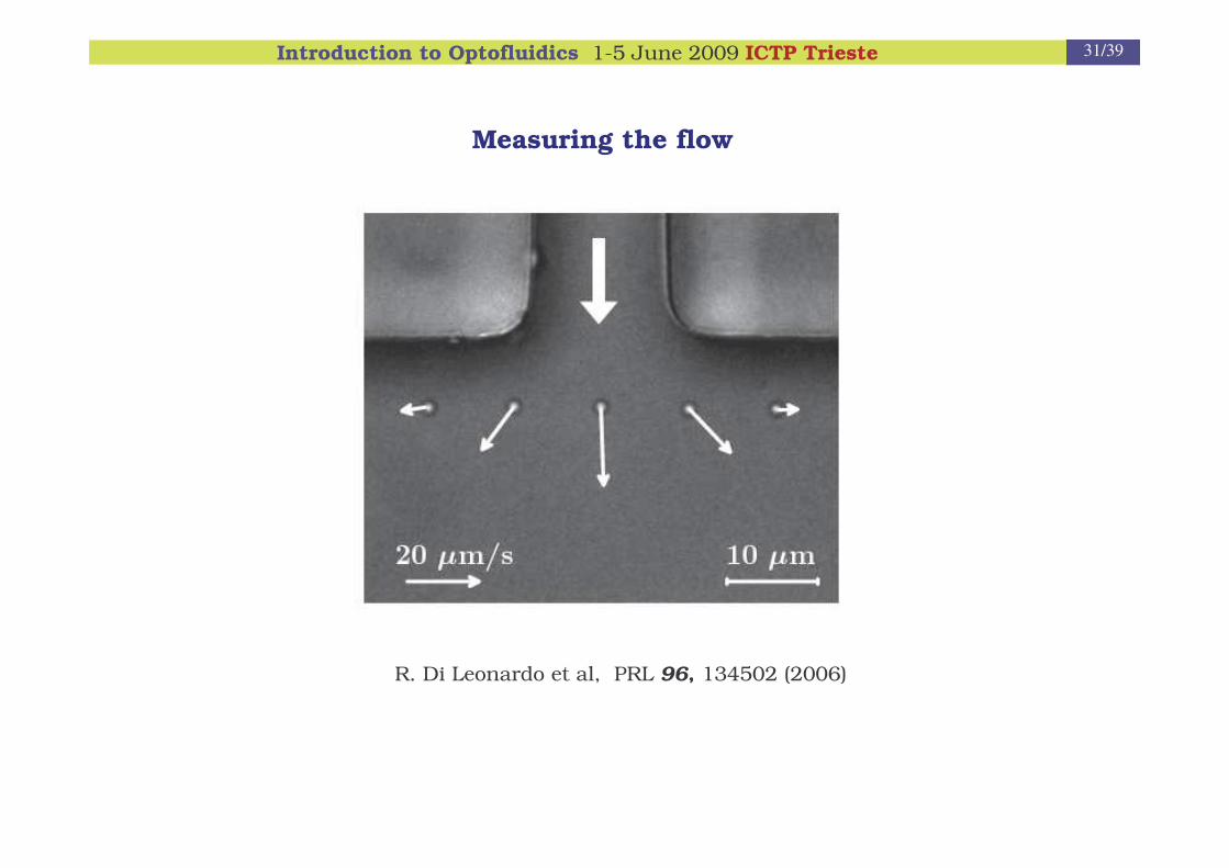
Measuring the flow
R. Di Leonardo et al, PRL 96, 134502 (2006)

Introduction to Optofluidics 1-5 June 2009 ICTP Trieste 32/39
� Why and how to change the environment of a cell ?
� Optically driven micro-pumps
a simple solution and the importance of the lateral view
� Optically driven vectors
functionalized beads and filled liposomes

Introduction to Optofluidics 1-5 June 2009 ICTP Trieste 33/39
Functionalized silica beads
COOH-NH2
Filled liposomes
2 um 5 um
• The vectors are optically driven to precise defined location
• Delivery by contact (beads) or breaking the liposome

Introduction to Optofluidics 1-5 June 2009 ICTP Trieste 34/39
SpatialLight
Modulator
CCD
Tube Lens
M
DM
Microscope objective1.4 NA, 100X
Sample cell (Petri dish) + capillary containing vesicles
Sample cell motorized movement
DM – Dichroic MirrorsM – MirrorL – Lenses
L L
L L
Ar Laser –fluorescence514 nm
DM
White light illumination+ Condenser
IR Trap Laser 1064 nm
UV pulsedLaser�-dissection347 nm BS
L L
Objectivemotorized movement
fluorescence
fused vesicle
transmission
image
DOE
CCD – CCD CameraDOE – DiffractiveOptical Element
LCM-CA (Laser Cell Manipulation – Chemical Analysis)Optical setup
The setup has been developed starting from an inverted Olympus microscope equipped with a PALM micro-dissection. CBM-TASCFunctions: cell and vectors manipulation, fluorescence imaging, micro-dissection and micro-Raman spectroscopy (to come).

Introduction to Optofluidics 1-5 June 2009 ICTP Trieste 35/39
The vectors (beads or liposomes) are first placed in a capillary which is introduced in the sample cell and then the vectors optically transported
Sample cell Capillary
Cell Vector
LOCALIZED DELIVERY OF BDNF BY MEANS OF OPTICAL TWEEZERS

Introduction to Optofluidics 1-5 June 2009 ICTP Trieste 36/39
BDNF functionalized bead
PAOLO BEUZER – MSc thesis – 10/2008
BDNF = Brain Derived Neurotrophic Factor
Acknowledgment: Prof. Enrico TONGIORGI, Univ. Trieste

Introduction to Optofluidics 1-5 June 2009 ICTP Trieste 37/39
Low Ca2+
High Ca2+
Ca2+ fluorescence
Elisa D’ESTE PhD student

Introduction to Optofluidics 1-5 June 2009 ICTP Trieste 38/39
Filled liposomes
Liposome positioned on an axonFluorescence imaging
Liposome fusion
This is a proof of concept, preliminary results.
In both cases, liposmes are filled with a fluorophor.
Introduction to Optofluidics 1-5 June 2009 ICTP Trieste 39/39
Enrico Ferrari – graduate, PhD student, postdoc, 2009 – LMB Cambridge
Silvia Santucci – postdoc
Elisa D’Este – PhD student 2009 �
Federica Tavano - PhD student 2009 �
Ali Reza Moradi – PhD student (2009 defended) ICTP Trieste/ Univ Iran
Lara Selvaggi – visiting PhD student (2008)
Valeria Garbin - PhD student (2007 defended) � Univ Twente
Paolo Beuzer – MSc 2008 � Univ Mainz
Asiya Giniatulina – MSc student 2007 � Univ Amsterdam
Enzo Di Fabrizio – former leader LILIT group at TASC
Federico Salvador – mechanical technician
Acknowledgments


