CHAPTER2 SUBSOIL EXPLORATION 2.1 SOIL EXPLORATION All office, laboratory and field worksare done in order to explore the subsurface of soil or rock conditions at any given site to obtain the necessary information required in design and construction. Subsoil exploration is the first step in the design of a foundation system. Soil exploration consists essentially of boring, sampling and testing. Mainly, planning of subsoil exploration involves three phases; reconnaissance phase, preliminary site investigation phase, and detailed site investigation phase. 2.1.1 RECONNAISSANCE PHASE This phase consists of: (a) Collection of all available information, and (b) Reconnaissance of the site. So that, it will indicate any settlement limitations and help to estimate foundation loads. 2.1.2 A PRELIMINARY SITE INVESTIGATION PHASE This phase consists of: (a) Preliminary design data that satisfy building code requirements, and (b) Number and depth of boreholes. So,it involves knowing of the distribution of structural loads which is required in the design of foundations. Also, a few borings or tests pits are to be opened to establish the stratification types of soil and location of water table. In addition to, one or more borings should be taken to rock when the initial boreholes indicate that the upper soil is loose or highly compressible. 2.1.3 A DETAILED SITE INVESTIGATION PHASE In this phase, additional boreholes, samples will be required for zones of poor soil at smaller spacing and locations which can influence the design and construction of the foundation. Prepared by: Dr. Farouk Majeed Muhauwiss Civil Engineering Department – College of Engineering Tikrit University
Transcript
CHAPTER2
SUBSOIL EXPLORATION 2.1 SOIL EXPLORATION
All office, laboratory and field worksare done in order to explore the subsurface of soil or rock conditions at any given site to obtain the necessary information required in design and construction. Subsoil exploration is the first step in the design of a foundation system. Soil exploration consists essentially of boring, sampling and testing.
Mainly, planning of subsoil exploration involves three phases; reconnaissance phase, preliminary site investigation phase, and detailed site investigation phase.
2.1.1 RECONNAISSANCE PHASE
This phase consists of: (a) Collection of all available information, and (b) Reconnaissance of the site.
So that, it will indicate any settlement limitations and help to estimate foundation loads. 2.1.2 A PRELIMINARY SITE INVESTIGATION PHASE
This phase consists of: (a) Preliminary design data that satisfy building code requirements, and
(b) Number and depth of boreholes. So,it involves knowing of the distribution of structural loads which is required in the design
of foundations. Also, a few borings or tests pits are to be opened to establish the stratification types of soil and location of water table. In addition to, one or more borings should be taken to rock when the initial boreholes indicate that the upper soil is loose or highly compressible. 2.1.3 A DETAILED SITE INVESTIGATION PHASE In this phase, additional boreholes, samples will be required for zones of poor soil at smaller spacing and locations which can influence the design and construction of the foundation.
Prepared by: Dr. Farouk Majeed Muhauwiss Civil Engineering Department – College of Engineering
Tikrit University
Foundation Engineering Chapter 2: Subsoil Exploration
15
2.2 DRILLING OR BORING • Definition:It is a procedure of advancing a hole into ground.
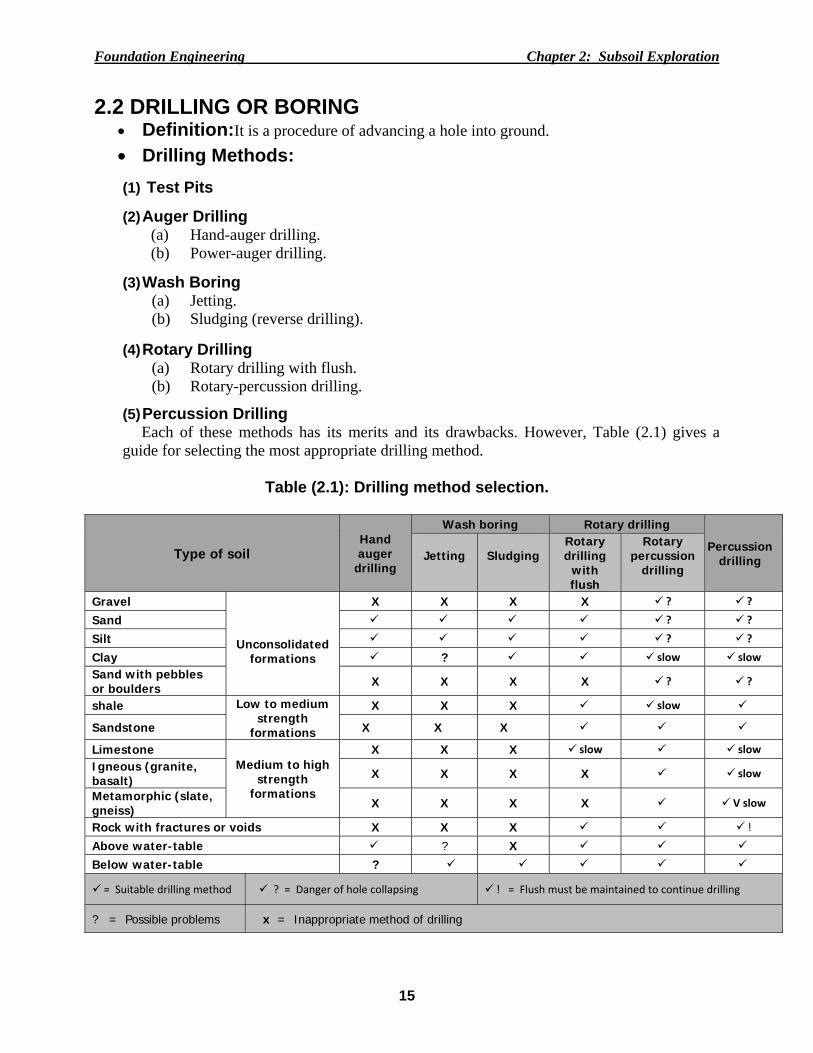
(5) Percussion Drilling Each of these methods has its merits and its drawbacks. However, Table (2.1) gives a
guide for selecting the most appropriate drilling method.
Table (2.1): Drilling method selection.
Type of soil Hand auger
drilling
Wash boring Rotary drilling
Percussion drilling
Jetting
Sludging
Rotary drilling
with flush
Rotary percussion
drilling
Gravel
Unconsolidated
formations
X X X X ? ? Sand ? ? Silt ? ? Clay ? slow slow
Sand with pebbles or boulders X X X X ? ?
shale Low to medium strength
formations
X X X slow
Sandstone X X X
Limestone Medium to high
strength formations
X X X slow slow
Igneous (granite, basalt) X X X X slow
Metamorphic (slate, gneiss) X X X X V slow
Rock with fractures or voids X X X ! Above water-table ? X Below water-table ?
= Suitable drilling method ? = Danger of hole collapsing ! = Flush must be maintained to continue drilling
? = Possible problems x = Inappropriate method of drilling
Foundatio
2.2.1 TA p
in detail
Fig. 2.1): Advanta
• In• Pr• L• L• Fi
Disadva
• D• D
co• Ex• To• W
en• U
re
on Engineeri
EST PITSpit is dug eith
the subsoil s
ages: nexpensive. rovide detailarge quantitarge blocks ield tests can
antages: Depth limitedDeep pits uneonstruction. xcavation beoo many pit
When the soilntering the p
Unsuitable inesistancetest
ing
S her by hand
strata and ta
led informaties of disturbof undisturbn be conduct
d to about 6meconomical s
elow grounds may scar sl is unstable
pit and accomn granular (N-value) is
(1) Claye
or by a back
ake disturbed
tion of stratigbed soils can
bed samples ted at the bo
m. such as in ca
dwater (high site and reque and has a tmpanied by c
soils belos required.
Walls of test ey silt (2) Sand
Fig.
16
khoe. Probab
d or undistur
graphy. n be obtainedcan be carve
ottom of the p
ase of invest
water table)uire backfill stendency to certain risksowwater lev
pit indicate fody silt (3) Clea
(2.1): Test
C
bly in a test p
rbed sample
d for testinged out from tpit.
tigationthat i
) and into rocsoils. collapse, thi. velor when
our layers n sand (4) San
pits.
Chapter 2: Su
pit, the engin
es at the desi
g. the pits.
involves bas
ck difficult a
is prevents t
n the stand
dy gravel
ubsoil Explor
neer can exa
ired location
sement
and costly.
the engineer
dard penetr
ration
amine
n (see
from
ration
Foundatio
2.2.2 A
(a) HTh
handlebaSeveral navailable
a. Hb. Shc. Iw
Advanta• In• Si• N• Po• U• G
Disadva
• Sl• D• L• U• C
a. Hel
on Engineeri
AUGER DR
Hand-Augehe auger ofr. Then with
new auger se in different
Helical Augerhort flight Awan Auger.
ages: nexpensive. imple to ope
Not dependenortable.
Used in uncasGroundwater
antages: low compare
Depth limitedabor intensiv
Undisturbed sCannot be use
ical (worm ty
ing
RILLING
rs f (10-20) cmhdrawing anections are atypes such a
r. Auger, and
erate and mant on terrain.
sed holes, anlocation can
ed with othed to about 6mve. samples can ed in rock, st
ypes) Augers
m in diametnd emptyingadded up toas (see Fig. 2
aintain.
nd n easily be id
er methods.m.
be taken ontiff clays, dr
b. Short
Fig. (2.2)
17
ter is rotatedg the soil-lad the require2.2):
dentified and
ly for soft clry sand, or ca
t flight Auger
): Hand-au
C
d by turningden auger tod depth is r
d measured.
lay deposit, aliches soils
r c.Iwan
ugers.
Chapter 2: Su
g and pushio remove threached. The
and .
n (posthole) A
ubsoil Explor
ing down ohe excavatedese augers c
Auger
ration
n the d soil. an be
Foundatio
(b) PTr
hole 100 diameter
Advanta• U• Q• U• U• G
Disadva
• D• Si
a. C
on Engineeri
Power-Augeruck or tractto 250 mm (see Fig.2.3
ages: Used in clay oQuick. Used in uncasUndisturbed sGroundwater
antages: Depth limited
ite must be a
Continuous fli
ing
ers tor mountedin diameter).
or sand or si
sed holes, thsamples can location can
d to about 15accessible to
ight augers.
Fig. (2
d type rig an. These auge
lt soils.
herefore no nbe obtained
n easily be id
5m.At greateo motorized v
2.3): Powe
18
d equipped ers can have
need for usind quite easilydentified and
er depth, drilvehicle.
b. Solid‐s
r or mechan
C
with continue a solid or h
ng drilling my, and d measured.
ling become
stem auger
nical-auger
Chapter 2: Su
uous flight ahollow stem
mud.
es expansive
c. Hollow
rs.
ubsoil Explor
augers that bof (20-75) c
e, and
w‐steam auge
ration
bore a cm in
er
Foundatio
2.2.3 W
Wateis rotated
(a)Jettin
Methup ththe ffoot-
(b) Slud
Methvalvethe breserthe d
on Engineeri
WASH BO
er is pumpedd and droppe
ng Method
hod:Water he borehole oformation is -powered tre
ging(Reve
hod: A hole can be useborehole anrvoir is needdrill-pipe, pre
ing
ORING
d to bottom od to produce
is pumped dor drill-pipehelped by
eadle pump o
rse Jetting
llow pipe ofed to improvnnulus (ring)ded at the topeferably mad
of borehole ae a chopping
Fig. (2.4):
down the cen bringing wirotation, an
or a small int
g)
f steel is movise successfu) and back p of the borede of metal,
19
and soil wasg action (see
Wash bori
ntre of the drith it cuttingd by the upternal-comb
oved up andfully – provid
up the drilehole for rechelp cutting
C
shings are retFig. 2.4).
ng rig.
rill-rods, emgs and debrisp-and-down ustion pump
d down in thdes a pumpillpipe, bringcirculation. Sg efficiency.
Chapter 2: Su
turned to sur
erging as a js. The washimotion of t
p is equally s
he borehole ing action. Wging debris Simple teeth
ubsoil Explor
rface. A dril
jet. It then reing and cuttihe drill-strinsuitable.
while a oneWater flows
with it. A h at the botto
ration
ll bit
eturns ing of ng. A
e-way down small om of
Foundation Engineering Chapter 2: Subsoil Exploration
20
Advantages:
• The equipment can be made from local, low-cost materials, and it is simple to use. • Possible above and below the water-table. • Suitable for clay to silt clay, silt soils and unconsolidated rocks, and • Used in uncased holes.
Disadvantages:
• Slow drilling through stiff clays and gravels. • Undisturbed soil samples cannot be obtained. • Water is required for pumping. • Difficulty in obtaining accurate location of groundwater level. • Boulders can prevent further drilling, and • Depth is limited to about 30m.
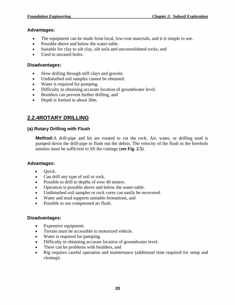
2.2.4ROTARY DRILLING (a) Rotary Drilling with Flush
Method:A drill-pipe and bit are rotated to cut the rock. Air, water, or drilling mud is pumped down the drill-pipe to flush out the debris. The velocity of the flush in the borehole annulus must be sufficient to lift the cuttings (see Fig. 2.5).
Advantages:
• Quick. • Can drill any type of soil or rock. • Possible to drill to depths of over 40 meters. • Operation is possible above and below the water-table. • Undisturbed soil samples or rock cores can easily be recovered. • Water and mud supports unstable formations, and • Possible to use compressed air flush.
Disadvantages:
• Expensive equipment. • Terrain must be accessible to motorized vehicle. • Water is required for pumping. • Difficulty in obtaining accurate location of groundwater level. • There can be problems with boulders, and • Rig requires careful operation and maintenance (additional time required for setup and
cleanup).
Foundatio
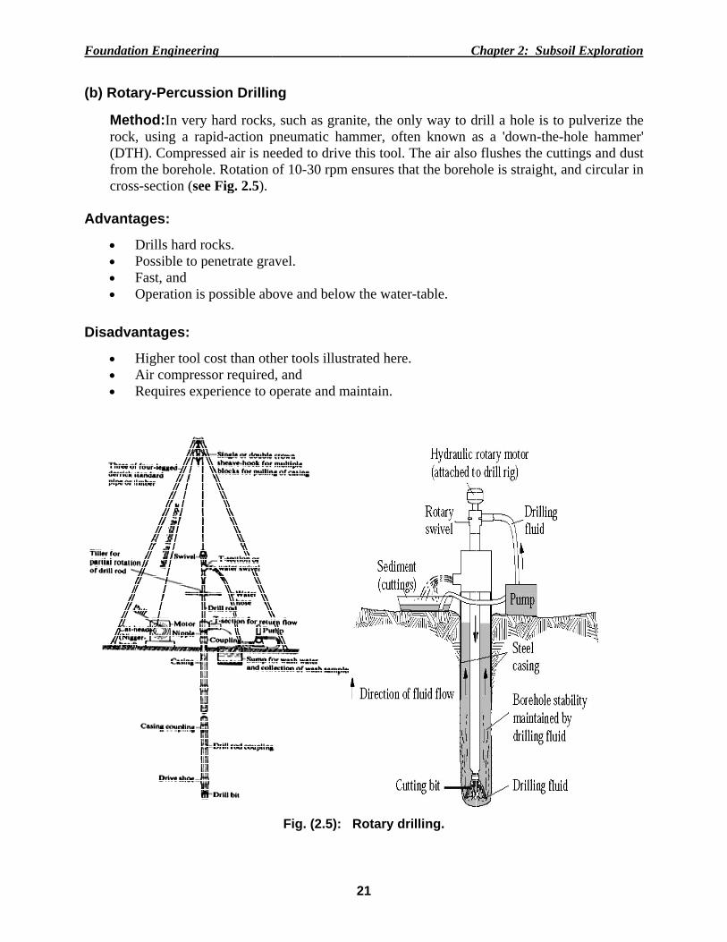
(b) Rota
Methrock,(DTHfromcross
Advanta
• D• P• F• O
Disadva
• H• A• R
on Engineeri
ary-Percus
hod:In very, using a raH). Compres
m the borehols-section (se
ages:
Drills hard rPossible to pFast, and Operation is
antages:
Higher tool Air compresRequires exp
ing
sion Drillin
y hard rocksapid-action pssed air is nele. Rotation
ee Fig. 2.5).
rocks. penetrate gra
s possible ab
cost than othssor requiredperience to o
ng
, such as grapneumatic heeded to drivof 10-30 rpm
avel.
ove and belo
her tools illud, and operate and m
Fig. (2.5):
21
anite, the onhammer, ofteve this tool. m ensures th
ow the water
ustrated here
maintain.
: Rotary dr
C
nly way to den known aThe air also
hat the boreh
r-table.
.
rilling.
Chapter 2: Su
drill a hole isas a 'down-to flushes the hole is straigh
ubsoil Explor
s to pulverizthe-hole hamcuttings and
ht, and circu
ration
ze the mmer' d dust ular in
Foundation Engineering Chapter 2: Subsoil Exploration
22
2.2.5 PRECUSSION DRILLING
Method:The lifting and dropping of a heavy (+50kg) cutting tool will chip and excavate material from a hole. The tool may be fixed to rigid drill-rods or to a rope or cable. With a mechanical winch, depths of hundreds of meters can be reached.
Advantages:
• Simple to operate and maintain. • Suitable for a wide variety of rocks. • Operation is possible above and below the water-table. • It is possible to drill to considerable depths, and • Can be used for boring observation wells.
Disadvantages:
• Slow, compared with other methods. • Equipment can be heavy. • Problems can occur with unstable rock formations. • Water is needed for dry holes to help remove cuttings, and • Due to high disturbance of soil, the obtained samples can not be used for testing.
2.3UNDERGROUND WATER IN THE TEST HOLE
The depth of the water table (W.T.) as measured during drilling and sampling should be carefully evaluated. It is always necessary to wait for at least 24 hours to check on the stabilized water table for the final measurement.The technician should plug the top of the drill holes and flag them for identification. Care is required to ensure that the water level in the drill hole is always maintained. Any sudden drop or rise of the water table or a sudden change in the penetration resistance should be carefully recorded in the field logs of borings. 2.4 GEOPHYSICAL METHODS
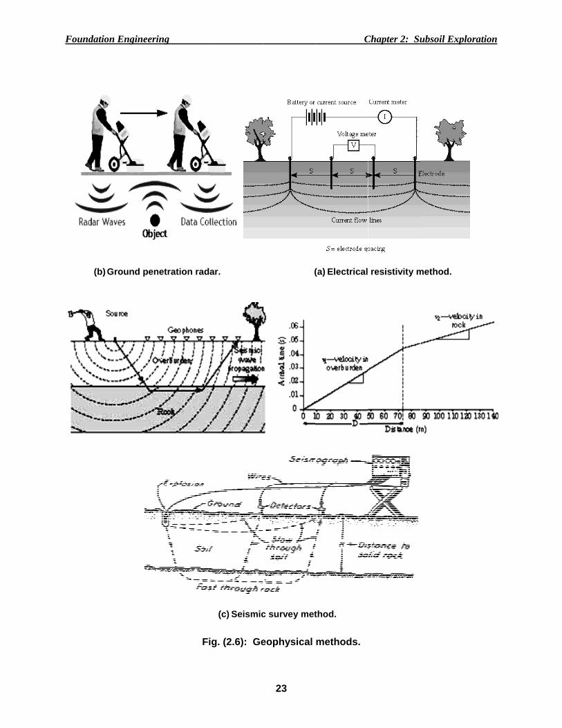
These methodsrepresent indirect methods of subsoilexploration and mainly consist of: (1) Ground Penetration Radar (GPR). (2) Electrical Resistivity Method (ERM) (2) Electromagnetic Method (EM), and (4) Seismic Methods. In subsoil investigation, the seismic methodsare most frequently used. Thesemethods are
based on the variation of the wave velocity in different earth materials.They involve in generating a sound wave in the rock or soil, using a sledgehammer,a falling weight, or a small explosive charge, and then recording its receptionat a series of geophones located at various distances from the shot point, as shownin Fig.(2.6). The time of the refracted sound arrival at each geophone is noted froma continuous reader. Typical seismic velocities of earth materials in (m/sec) are shownin Table (2.1).
Foundatio
(b)
on Engineeri
Ground pen
ing
Fi
netration rada
ig. (2.6): Ge
(c) Seismic
ar.
23
eophysical
c survey met
(
C
methods.
thod.
(a) Electrical
Chapter 2: Su
resistivity m
ubsoil Explor
method.
ration
Foundation Engineering Chapter 2: Subsoil Exploration
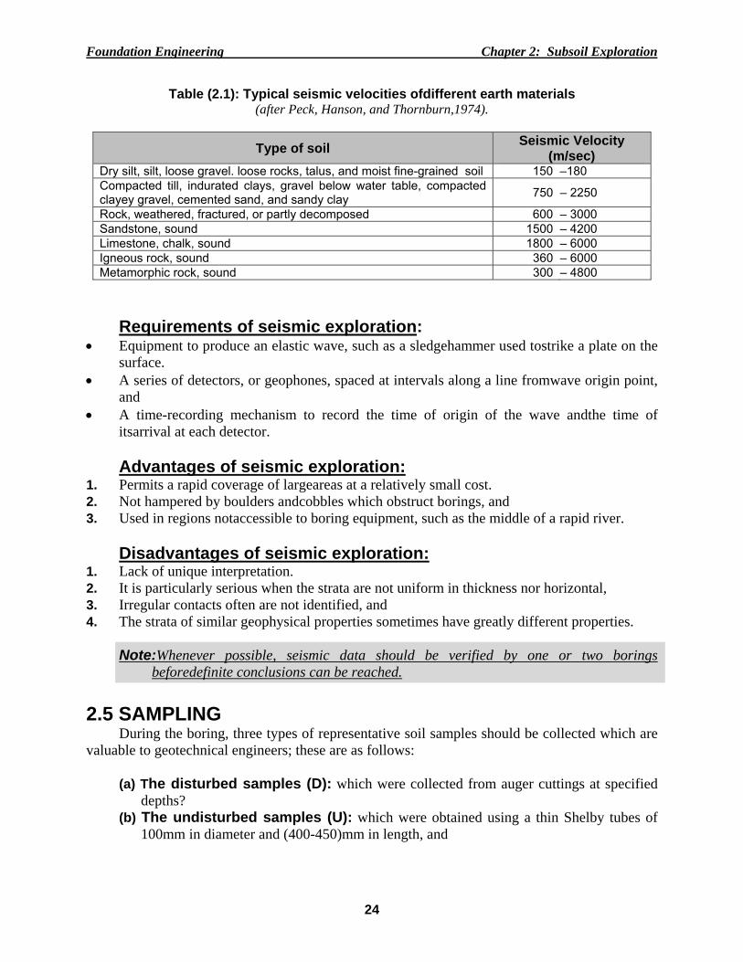
Rock, weathered, fractured, or partly decomposed 600 – 3000 Sandstone, sound 1500 – 4200 Limestone, chalk, sound 1800 – 6000 Igneous rock, sound 360 – 6000 Metamorphic rock, sound 300 – 4800
Requirements of seismic exploration:
• Equipment to produce an elastic wave, such as a sledgehammer used tostrike a plate on the surface.
• A series of detectors, or geophones, spaced at intervals along a line fromwave origin point, and
• A time-recording mechanism to record the time of origin of the wave andthe time of itsarrival at each detector.
Advantages of seismic exploration:
1. Permits a rapid coverage of largeareas at a relatively small cost. 2. Not hampered by boulders andcobbles which obstruct borings, and 3. Used in regions notaccessible to boring equipment, such as the middle of a rapid river.
Disadvantages of seismic exploration: 1. Lack of unique interpretation. 2. It is particularly serious when the strata are not uniform in thickness nor horizontal, 3. Irregular contacts often are not identified, and 4. The strata of similar geophysical properties sometimes have greatly different properties.
Note:Whenever possible, seismic data should be verified by one or two borings
beforedefinite conclusions can be reached. 2.5 SAMPLING
During the boring, three types of representative soil samples should be collected which are valuable to geotechnical engineers; these are as follows:
(a) The disturbed samples (D): which were collected from auger cuttings at specified
depths? (b) The undisturbed samples (U): which were obtained using a thin Shelby tubes of
100mm in diameter and (400-450)mm in length, and
Foundatio
(c)
Al
Fig
commonlthe split sof brass ltest at thsampler.
Sam
primarilydiameter geologist
A su
samples o
Fig
on Engineeri
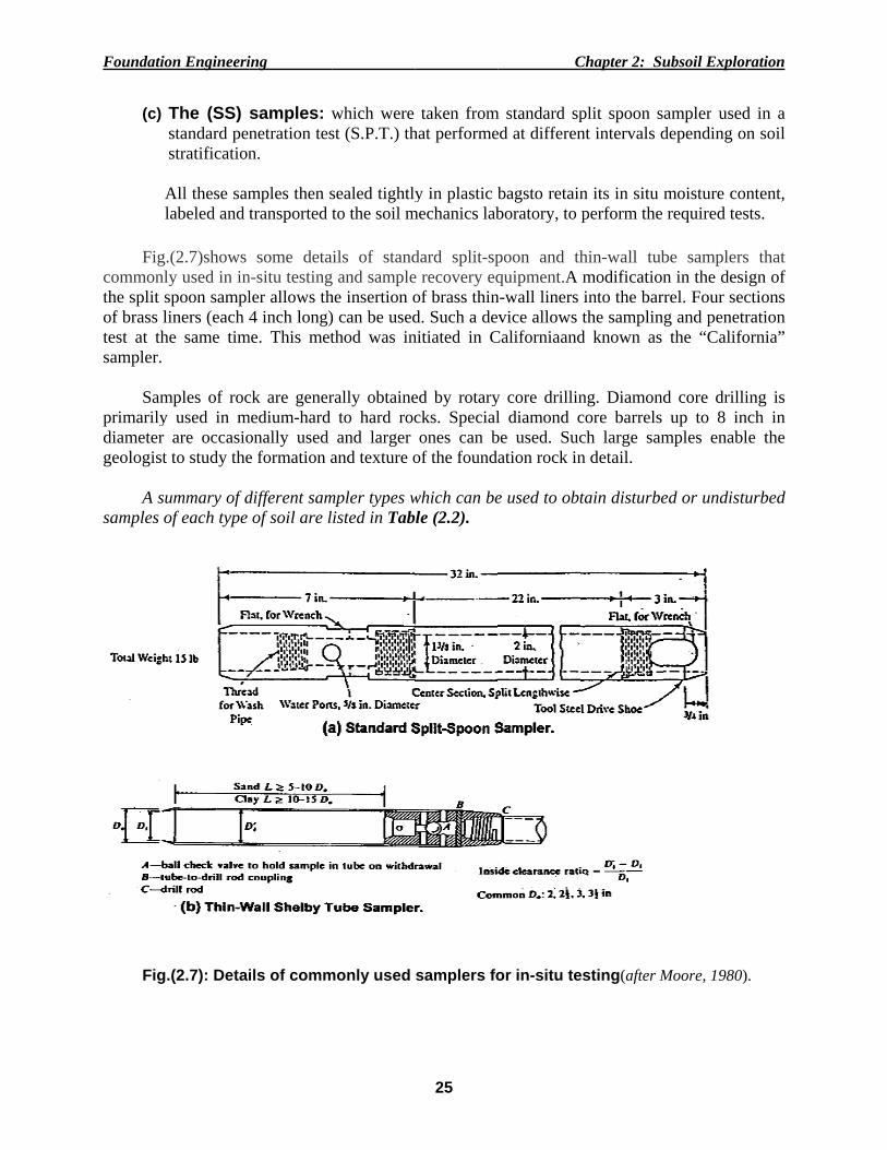
The (SS) standard penstratification All these samlabeled and
.(2.7)shows ly used in inspoon samplliners (each he same tim
mples of rocy used in m
are occasiot to study the
ummary of dof each type
.(2.7): Deta
ing
samples: wnetration tesn.
mples then stransported
some detan-situ testingler allows th4 inch long)
me. This met
ck are genermedium-hard onally used e formation a
different samof soil are l
ils of comm
which were st (S.P.T.) th
sealed tightlyto the soil m
ails of standg and samplehe insertion o) can be usedthod was in
rally obtaineto hard rocand larger
and texture o
mpler types wlisted in Tab
monly used
25
taken fromhat performe
y in plastic bmechanics lab
dard split-spe recovery eqof brass thind. Such a denitiated in C
ed by rotarycks. Specialones can b
of the found
which can bele (2.2).
samplers fo
C
m standard sped at differen
bagsto retainboratory, to
poon and thquipment.A
n-wall liners vice allows
Californiaand
y core drillinl diamond cbe used. Sucation rock in
e used to obt
or in-situ te
Chapter 2: Su
plit spoon snt intervals d
n its in situ mperform the
hin-wall tubmodificationinto the barthe samplin
d known as
ng. Diamondcore barrels ch large samn detail.
tain disturbe
esting(after M
ubsoil Explor
ampler useddepending on
moisture conrequired tes
be samplersn in the desirel. Four secg and penetrthe “Califo
d core drilliup to 8 in
mples enabl
ed or undistu
Moore, 1980)
ration
d in a n soil
ntent, sts.
s that ign of ctions ration ornia”
ing is nch in le the
urbed
).
Foundation Engineering Chapter 2: Subsoil Exploration
26
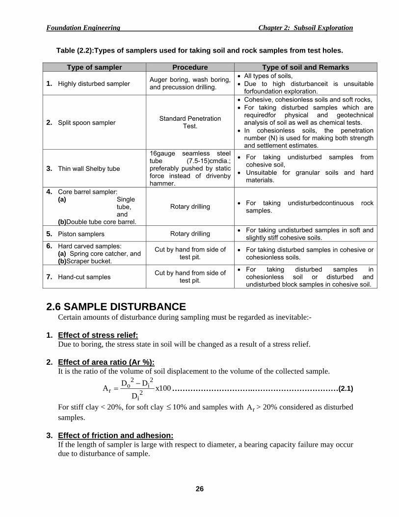
Table (2.2):Types of samplers used for taking soil and rock samples from test holes.
Type of sampler Procedure Type of soil and Remarks
• All types of soils, • Due to high disturbanceit is unsuitable
forfoundation exploration.
2. Split spoon sampler Standard Penetration Test.
• Cohesive, cohesionless soils and soft rocks, • For taking disturbed samples which are
requiredfor physical and geotechnical analysis of soil as well as chemical tests.
• In cohesionless soils, the penetration number (N) is used for making both strength and settlement estimates.
3. Thin wall Shelby tube
16gauge seamless steel tube (7.5-15)cmdia.; preferably pushed by static force instead of drivenby hammer.
• For taking undisturbed samples from cohesive soil,
• Unsuitable for granular soils and hard materials.
4. Core barrel sampler: (a) Single
tube, and
(b)Double tube core barrel.
Rotary drilling • For taking undisturbedcontinuous rock samples.
5. Piston samplers Rotary drilling • For taking undisturbed samples in soft and slightly stiff cohesive soils.
6. Hard carved samples: (a) Spring core catcher, and (b)Scraper bucket.
Cut by hand from side of test pit.
• For taking disturbed samples in cohesive or cohesionless soils.
7. Hand-cut samples Cut by hand from side of test pit.
• For taking disturbed samples in cohesionless soil or disturbed and undisturbed block samples in cohesive soil.
2.6 SAMPLE DISTURBANCE
Certain amounts of disturbance during sampling must be regarded as inevitable:-
1. Effect of stress relief: Due to boring, the stress state in soil will be changed as a result of a stress relief. 2. Effect of area ratio (Ar %):
It is the ratio of the volume of soil displacement to the volume of the collected sample.
100xD
DDA 2i
2i
2o
r−
= ………………………….……………………………(2.1)
For stiff clay < 20%, for soft clay ≤ 10% and samples with rA > 20% considered as disturbed samples.
3. Effect of friction and adhesion: If the length of sampler is large with respect to diameter, a bearing capacity failure may occur due to disturbance of sample.
Foundation Engineering Chapter 2: Subsoil Exploration
27
100xD
DDCi
ioi
−= ………………………………………..…………………(2.2)
where, =iC inside clearance = (0.3-0.4)% and not more than 1%. 4. Effect of the way in which the force is applied to the spoon:that meansby pushing
or driving or by constant rate of penetration. 2.7 TESTING
The tests performed on each type of the three different soil samples are as follows: As a rule, undisturbed samples (U) can betested for strength and compressibility to determine the stress strain characteristics of the material, in addition to classification and chemical tests. Whereas, disturbed (D) or (SS) samples as available were mainly used for physical and geotechnical analysis of soil as well as chemical tests. 2.7.1 LABORATORY TESTS:
The obtained samples should be tested according to the procedure of the American Society for Testing and Materials (ASTM) or the British Standards (BS) whichever is appropriate. The test program of the samples includes the followings:
1. Classification Tests: Sieve and hydrometer analysis,natural water content, Atterberge limits,specific gravity, andwet and dry unit weights.
2. Compaction Test: Modified Procter compaction test must be carried out on some soil samples to obtain the
maximum dry density )( .maxdγ and the relevant optimum moisture content (OMC).
3. Shear Strength and Compressibility Tests:
Unconfined or Triaxial compressive strength test and one-dimensional consolidation test. 4. Chemical Tests:
(ORG.)%,PH- value, Carbonate Content (CO3-2), and Chlorides Content (Cl-1)%.
2.7.2 FIELD TESTS
During the subsoil exploration, several field tests as given in Table (2.3),can be performed depending on the available testing equipments, required parameters for design of foundations, and the economic point of view.
Foundation Engineering Chapter 2: Subsoil Exploration
28
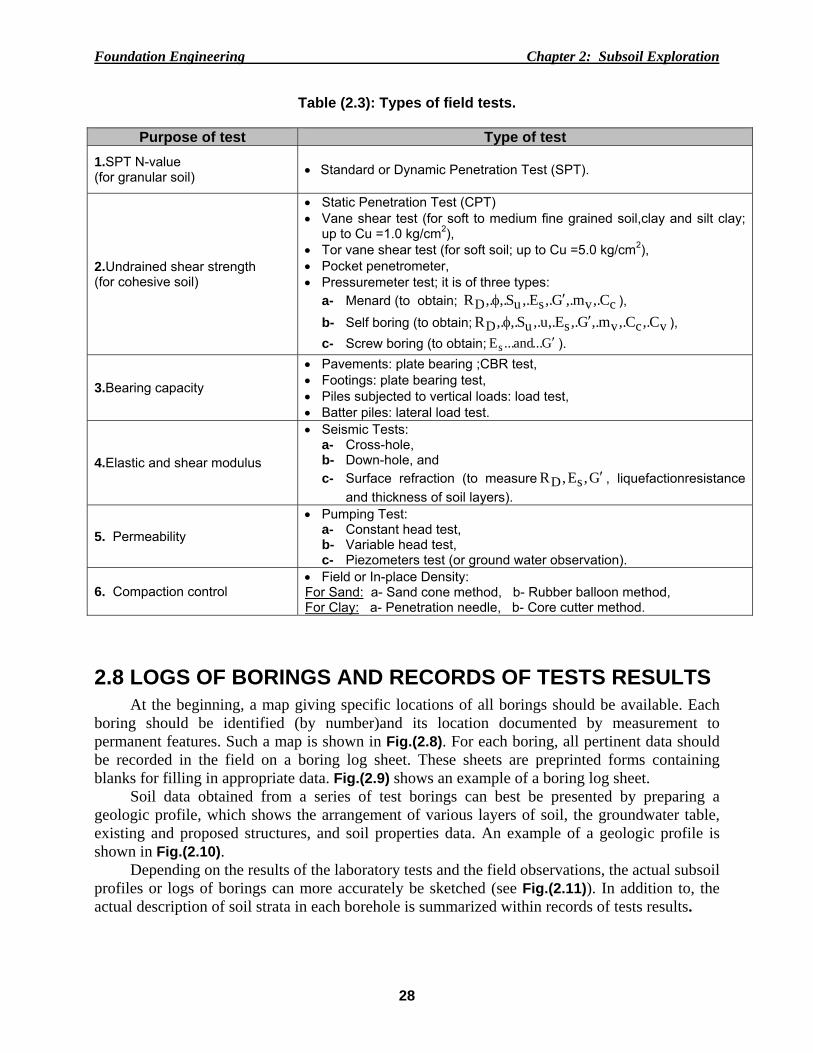
Table (2.3): Types of field tests.
Purpose of test Type of test 1.SPT N-value (for granular soil)
• Standard or Dynamic Penetration Test (SPT).
2.Undrained shear strength (for cohesive soil)
• Static Penetration Test (CPT) • Vane shear test (for soft to medium fine grained soil,clay and silt clay;
up to Cu =1.0 kg/cm2), • Tor vane shear test (for soft soil; up to Cu =5.0 kg/cm2), • Pocket penetrometer, • Pressuremeter test; it is of three types:
• Pumping Test: a- Constant head test, b- Variable head test, c- Piezometers test (or ground water observation).
6. Compaction control • Field or In-place Density: For Sand: a- Sand cone method, b- Rubber balloon method, For Clay: a- Penetration needle, b- Core cutter method.
2.8 LOGS OF BORINGS AND RECORDS OF TESTS RESULTS
At the beginning, a map giving specific locations of all borings should be available. Each boring should be identified (by number)and its location documented by measurement to permanent features. Such a map is shown in Fig.(2.8). For each boring, all pertinent data should be recorded in the field on a boring log sheet. These sheets are preprinted forms containing blanks for filling in appropriate data. Fig.(2.9) shows an example of a boring log sheet.
Soil data obtained from a series of test borings can best be presented by preparing a geologic profile, which shows the arrangement of various layers of soil, the groundwater table, existing and proposed structures, and soil properties data. An example of a geologic profile is shown in Fig.(2.10).
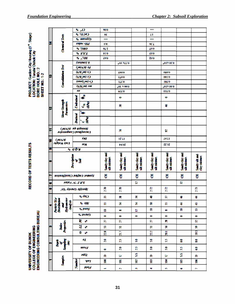
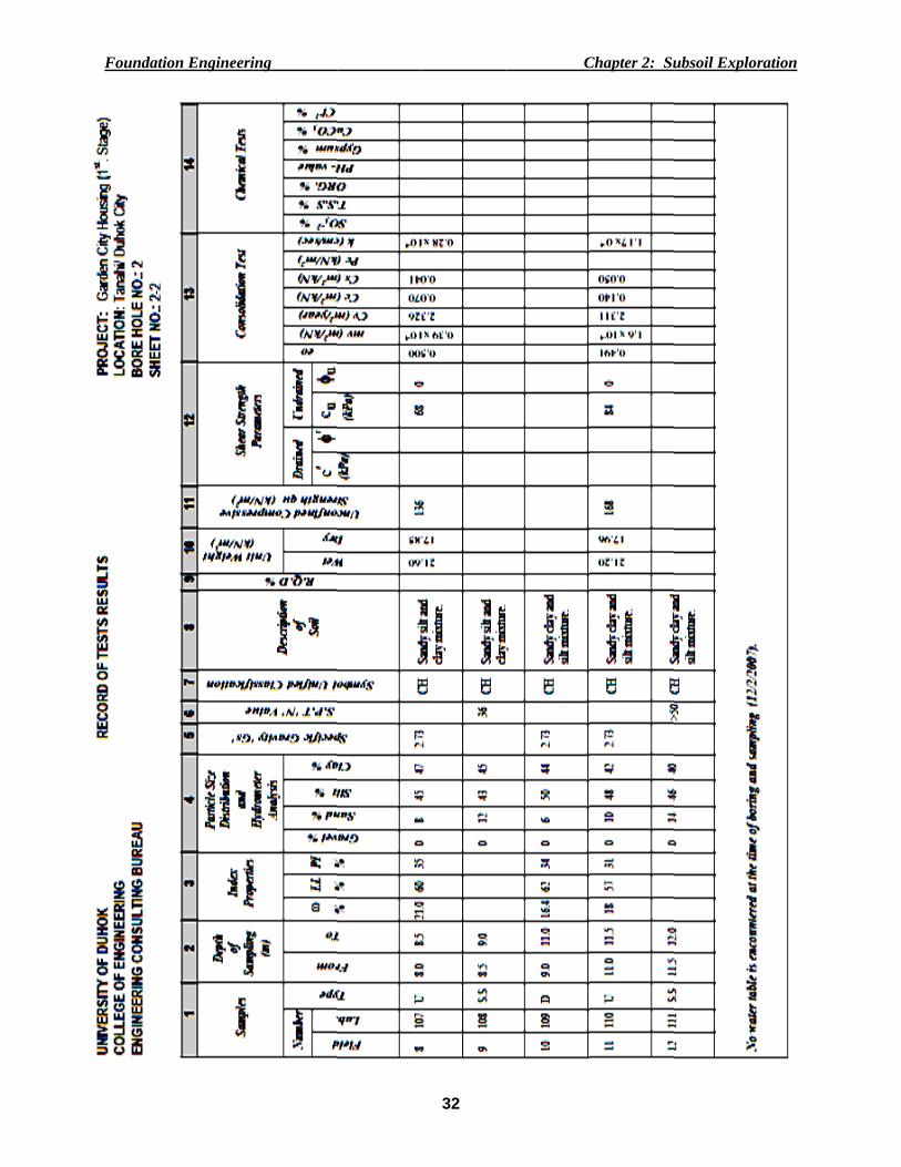
Depending on the results of the laboratory tests and the field observations, the actual subsoil profiles or logs of borings can more accurately be sketched (see Fig.(2.11)). In addition to, the actual description of soil strata in each borehole is summarized within records of tests results.
Foundation Engineering Chapter 2: Subsoil Exploration
29
DRILLING COMPANY, INC. BORE HOLE NO.: ------------- PROJECT: LOCATION: --------------------
Name ----------------------------------------------------Date Time Depth Casing at
Address ------------------------------------------------ ------------------------------------------------------------------------------- CASING (SIZE AND TYPE) --------------------------------- SAMPLE SPOON (SIZE AND TYPE) --------------------- HAMMER (CSG): WT. ------------, DROP ------------------ (SPOON): WT. ------------, DROP ------------------
DATE: STARTED --------------------------------------------, COMPLETED ----------------------, DRILLER ----------------------
Field Samples
Depth of Sampling (m) 'N'- Value
Visual Description of Soil No. Type From To 6 ′′ 6 ′′ 6 ′′
1 D 0.0 2.0 Black and grey moist fill, 2 U 2.0 4.0 Black peat.3 S.S 4.5 5.0 11 14 6 Sandy clay and silt mixture. 4 D 5.0 7.0 Sandy silt and clay mixture. 5 U 7.0 9.0 Silt with fine gravel and traces of fine sand.6 S.S 9.5 10.0 4 8 3 Sandy clay and silt mixture.
45m
Figure (2.8): Example map showing boring locations on site plan.
B-4
B-1 B-2
B-3
B-5 7.5m
15m
7.5m
30m15m 30m
90m
15m
Fig.(2.9): boring log sheet.
Foundation Engineering Chapter 2: Subsoil Exploration
30
Fig.(2.10):Example of geologic profile.
Sandy clay and
silt mixture
0
Natural ground surface (N.G.S.)
2
4
6
8
10
12
Dep
th (m
)
BH.no.1
Sandy clay and
silt mixture
E.O.B.
Sandy silt and
clay mixture
Sandy clay and
silt mixture
E.O.B.
Sandy clay and
silt mixture
E.O.B.
Fig.(2.11): Log of borings for 1st. stage of garden city housing project Tanahi District / Duhok city.
BH.no.2 BH.no.3
Foundatio
on Engineeriing
31
CChapter 2: Suubsoil Explorration
Foundatio
on Engineeriing
32
CChapter 2: Suubsoil Explorration
Foundation Engineering Chapter 2: Subsoil Exploration
33
2.9 NUMBER OF BOREHOLES It is a good practice in the beginning to take a few numbers of borings so that a soil profile
can be drawn with reasonable accuracy and then the preliminary program can be adjusted to suit subsoil conditions.
Obviously, the more boreholes and the closer they are spaced, the more accurate the resulting geologic profile. Boreholesnumber and layout may need to be changed as more information emerges, so that, an additional boreholes may be required during the survey.
For rough guidelines, if soil conditions are relatively uniform or the geological data are limited, Tables (2.4) and (2.5) can be used as a guide in planning of the preliminary program:
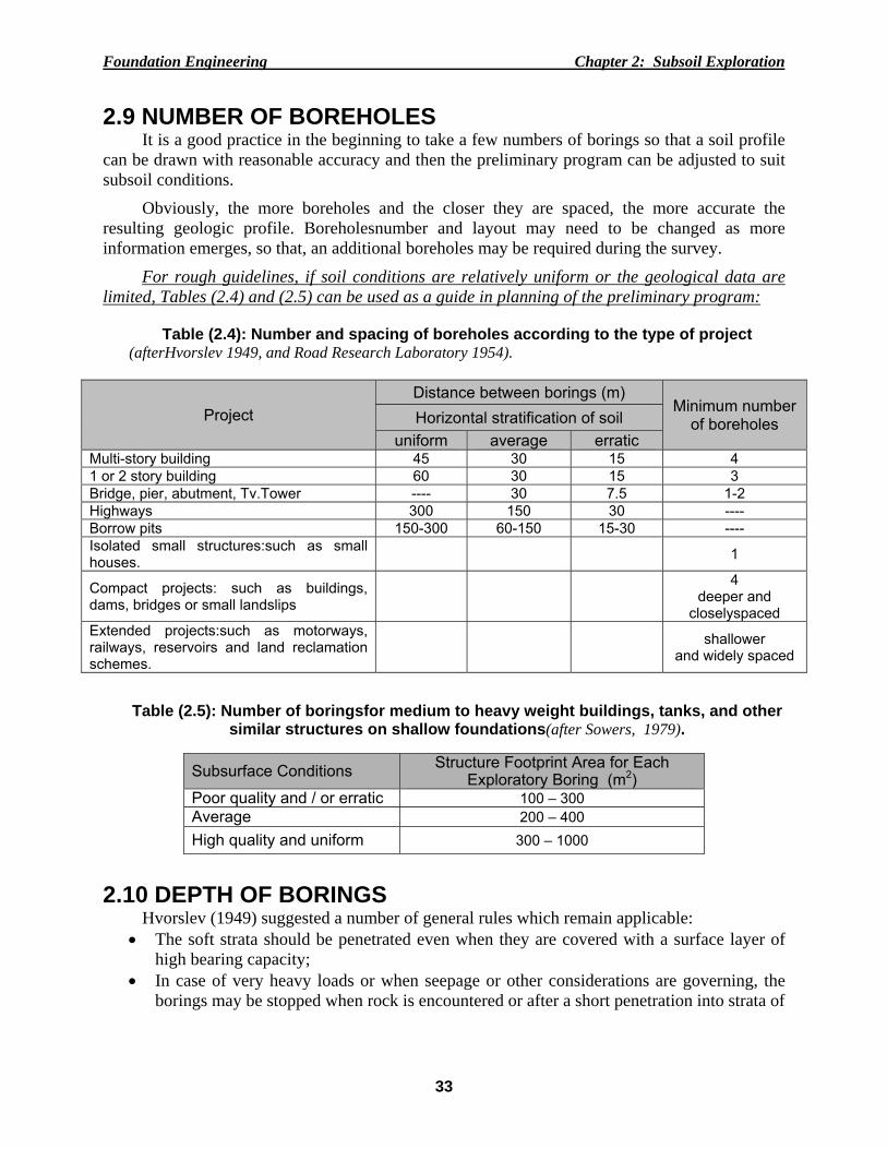
Table (2.4): Number and spacing of boreholes according to the type of project
(afterHvorslev 1949, and Road Research Laboratory 1954).
Project Distance between borings (m)
Minimum number of boreholes Horizontal stratification of soil
uniform average erratic Multi-story building 45 30 15 4 1 or 2 story building 60 30 15 3 Bridge, pier, abutment, Tv.Tower ---- 30 7.5 1-2 Highways 300 150 30 ---- Borrow pits 150-300 60-150 15-30 ---- Isolated small structures:such as small houses.
1
Compact projects: such as buildings, dams, bridges or small landslips
4 deeper and
closelyspaced Extended projects:such as motorways, railways, reservoirs and land reclamation schemes.
shallower and widely spaced
Table (2.5): Number of boringsfor medium to heavy weight buildings, tanks, and other similar structures on shallow foundations(after Sowers, 1979).
Subsurface Conditions Structure Footprint Area for Each Exploratory Boring (m2)
Poor quality and / or erratic 100 – 300 Average 200 – 400 High quality and uniform 300 – 1000
2.10 DEPTH OF BORINGS
Hvorslev (1949) suggested a number of general rules which remain applicable: • The soft strata should be penetrated even when they are covered with a surface layer of
high bearing capacity; • In case of very heavy loads or when seepage or other considerations are governing, the
borings may be stopped when rock is encountered or after a short penetration into strata of
Foundation Engineering Chapter 2: Subsoil Exploration
34
exceptional bearing capacity and stiffness, provided it is known from explorations in the vicinity of the area that these strata have adequate thickness or are underlain by still stronger formations. But, if these conditions are not satisfied, some of the borings must be extended until it has been established that the strong strata have adequate thickness irrespective of the character of the underlying material;
• When the structure is to be founded on rock, it must be verified that bedrock and not boulders have been encountered, and it is advisable to extend one or more borings from 3 to 6m into solid rock in order to determine the extent and character of the weathered zone of the rock; For rough guidelines,the following criteriacan be used for minimum depths,from
considerations of stress distribution or seepage,: 1. Foundations:
• All borings should extend below all deposits such as top soils, organic silts, peat, artificial fills, very soft and compressible clay layers;
• Boring should be sufficiently deep for checking the possibility of a weaker soil at greater depth which may settle under the applied load;
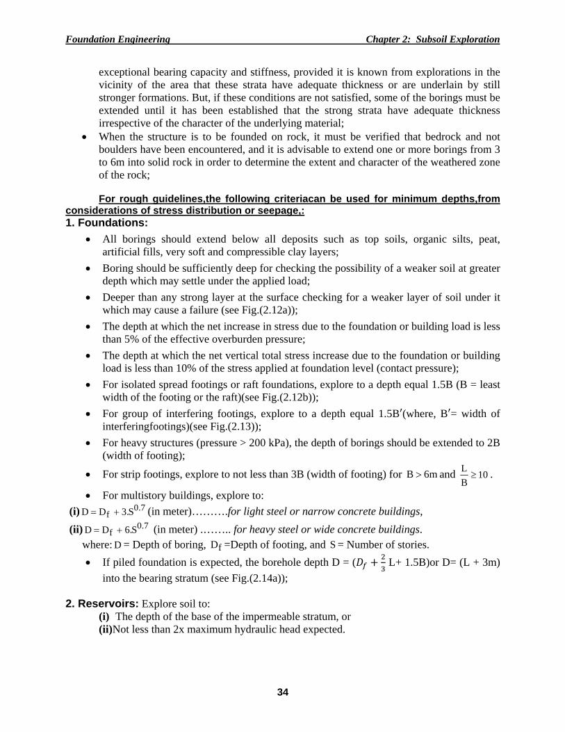
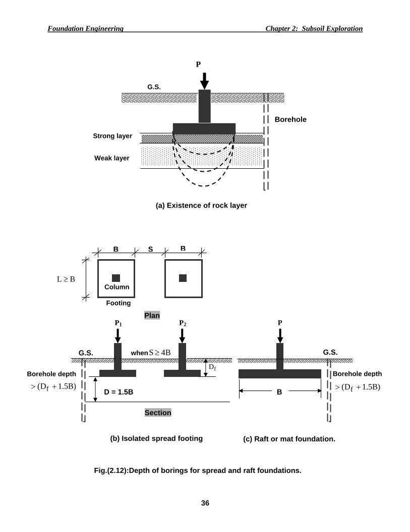
• Deeper than any strong layer at the surface checking for a weaker layer of soil under it which may cause a failure (see Fig.(2.12a));
• The depth at which the net increase in stress due to the foundation or building load is less than 5% of the effective overburden pressure;
• The depth at which the net vertical total stress increase due to the foundation or building load is less than 10% of the stress applied at foundation level (contact pressure);
• For isolated spread footings or raft foundations, explore to a depth equal 1.5B (B = least width of the footing or the raft)(see Fig.(2.12b));
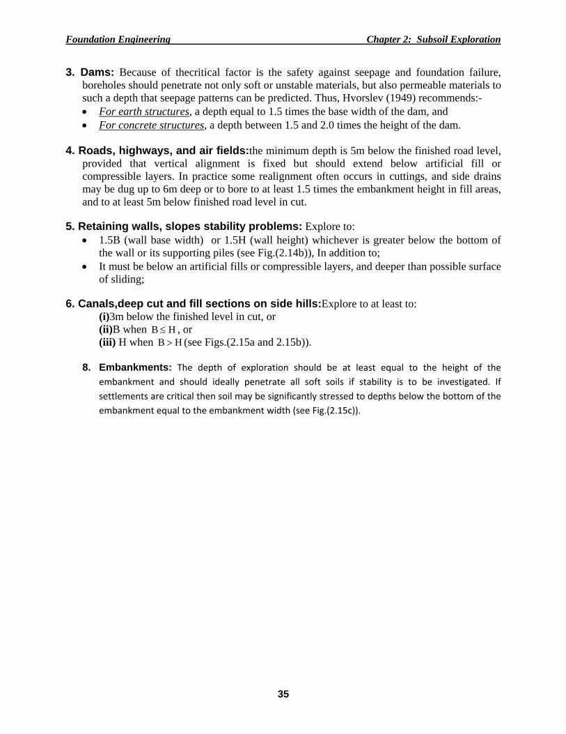
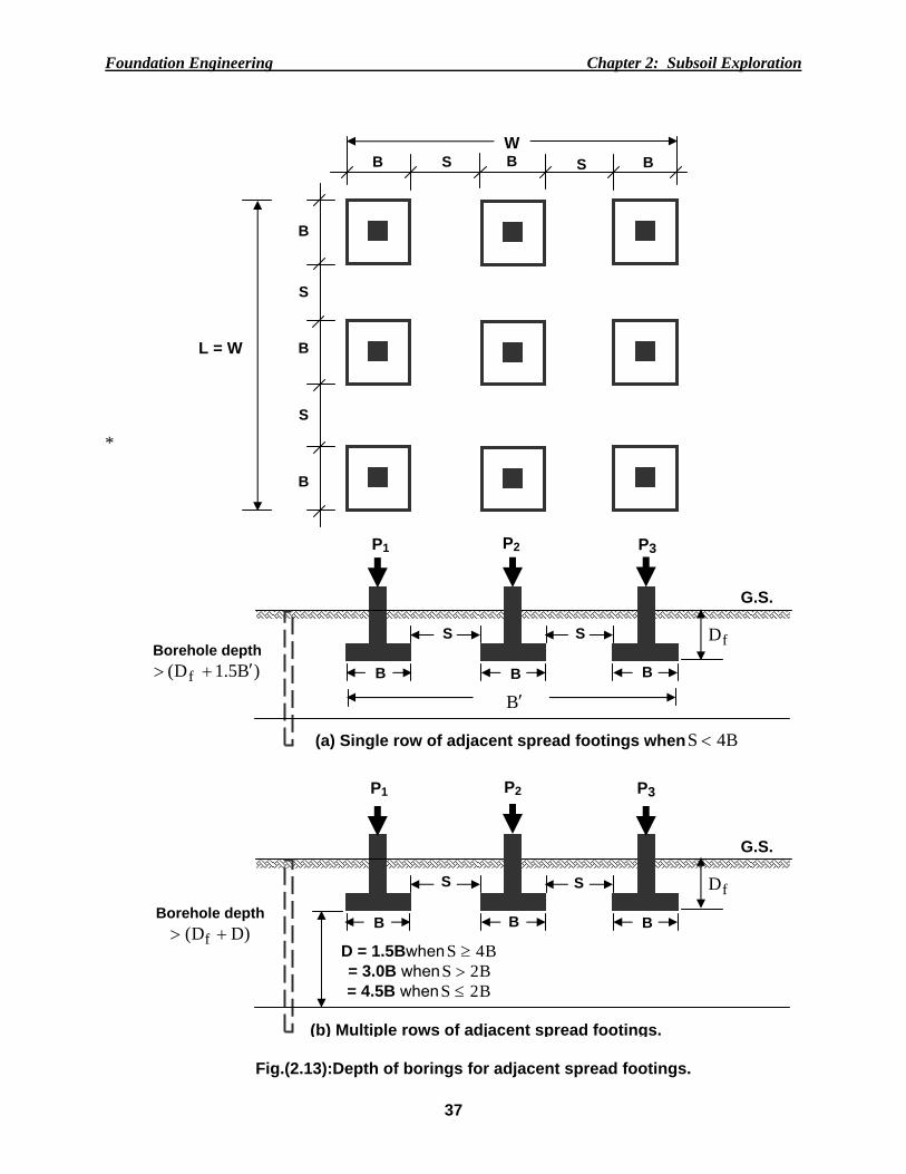
• For group of interfering footings, explore to a depth equal 1.5B (where, B = width of interferingfootings)(see Fig.(2.13));
• For heavy structures (pressure > 200 kPa), the depth of borings should be extended to 2B (width of footing);
• For strip footings, explore to not less than 3B (width of footing) for m6B > and 10BL≥ .
• For multistory buildings, explore to: (i) 7.0
f S.3DD += (in meter)……….for light steel or narrow concrete buildings, (ii) 7.0
f S.6DD += (in meter) .…….. for heavy steel or wide concrete buildings. where: D = Depth of boring, fD =Depth of footing, and S = Number of stories. • If piled foundation is expected, the borehole depth D = (
L+ 1.5B)or D= (L + 3m)
into the bearing stratum (see Fig.(2.14a));
2. Reservoirs: Explore soil to: (i) The depth of the base of the impermeable stratum, or (ii)Not less than 2x maximum hydraulic head expected.
Foundation Engineering Chapter 2: Subsoil Exploration
35
3. Dams: Because of thecritical factor is the safety against seepage and foundation failure, boreholes should penetrate not only soft or unstable materials, but also permeable materials to such a depth that seepage patterns can be predicted. Thus, Hvorslev (1949) recommends:- • For earth structures, a depth equal to 1.5 times the base width of the dam, and • For concrete structures, a depth between 1.5 and 2.0 times the height of the dam.
4. Roads, highways, and air fields:the minimum depth is 5m below the finished road level,
provided that vertical alignment is fixed but should extend below artificial fill or compressible layers. In practice some realignment often occurs in cuttings, and side drains may be dug up to 6m deep or to bore to at least 1.5 times the embankment height in fill areas, and to at least 5m below finished road level in cut.
5. Retaining walls, slopes stability problems: Explore to:
• 1.5B (wall base width) or 1.5H (wall height) whichever is greater below the bottom of the wall or its supporting piles (see Fig.(2.14b)), In addition to;
• It must be below an artificial fills or compressible layers, and deeper than possible surface of sliding;
6. Canals,deep cut and fill sections on side hills:Explore to at least to:
(i)3m below the finished level in cut, or (ii)B when HB ≤ , or (iii) H when HB > (see Figs.(2.15a and 2.15b)).
8. Embankments: The depth of exploration should be at least equal to the height of the
embankment and should ideally penetrate all soft soils if stability is to be investigated. If settlements are critical then soil may be significantly stressed to depths below the bottom of the embankment equal to the embankment width (see Fig.(2.15c)).
Foundation Engineering Chapter 2: Subsoil Exploration
36
P
Strong layer
(a) Existence of rock layer
G.S.
Borehole
Weak layer
BL ≥
B BS
Column
Footing
Plan
Borehole depth
D = 1.5B
Section
G.S. when B4S≥
(b) Isolated spread footing
P2
fD
)B5.1D( f +>
P1
B
G.S.
)B5.1D( f +>
P
Borehole depth
(c) Raft or mat foundation.
Fig.(2.12):Depth of borings for spread and raft foundations.
Foundation Engineering Chapter 2: Subsoil Exploration
37
*
B B S B SW
L = W
B
B
S
S
B
P1
Borehole depth )B5.1D( f ′+>
G.S.
(a) Single row of adjacent spread footings when B4S <
P2 P3
fD
B B B
S S
B′
D = 1.5Bwhen B4S ≥ = 3.0B when B2S > = 4.5B when B2S ≤
P1
Borehole depth )DD( f +>
G.S.
(b) Multiple rows of adjacent spread footings.
P2 P3
fD
B B B
S S
Fig.(2.13):Depth of borings for adjacent spread footings.
Foundation Engineering Chapter 2: Subsoil Exploration
38
P
(a) Piles
G.S.
Borehole depth
fD
B
)B5.1L32D( f ++>
Pile cap
Individual pressure bulbs combined pressure bulb
Rock or hard layer
L32
L
(b) Retaining walls
H
Depth of B.H.= 1.5Bor 1.5H whichever is greater
B
G.S.
Backfill Soil
Base Soil
G.S.
Fig.(2.14): Depth of borings for piles, and retaining walls.
Foundation Engineering Chapter 2: Subsoil Exploration
39
(a) Deep cut and fills sections on side
Depth of borehole= 3m mimm.or
= B when B≤ H or = H when B> H
H
B
Cut
Fill
Cut
Fill Side hill
Fill
(b) Normal section of a canal.
(c) High embankment
Depth of borehole = H minm.
H
Fig.(2.15): Depth of borings for cuts and fills, canals, and embankments.
Depth of borehole= 3m mimm.
Foundation Engineering Chapter 2: Subsoil Exploration
40
2.11 FIELD LOAD TEST It is a method to investigate the stress-strain (or load-settlement) relationship of soils. Then,
the results are used in estimating the bearing capacity. In this test, the load is applied on a model footing and the amount of load necessary to induce a given amount of settlement is measured.
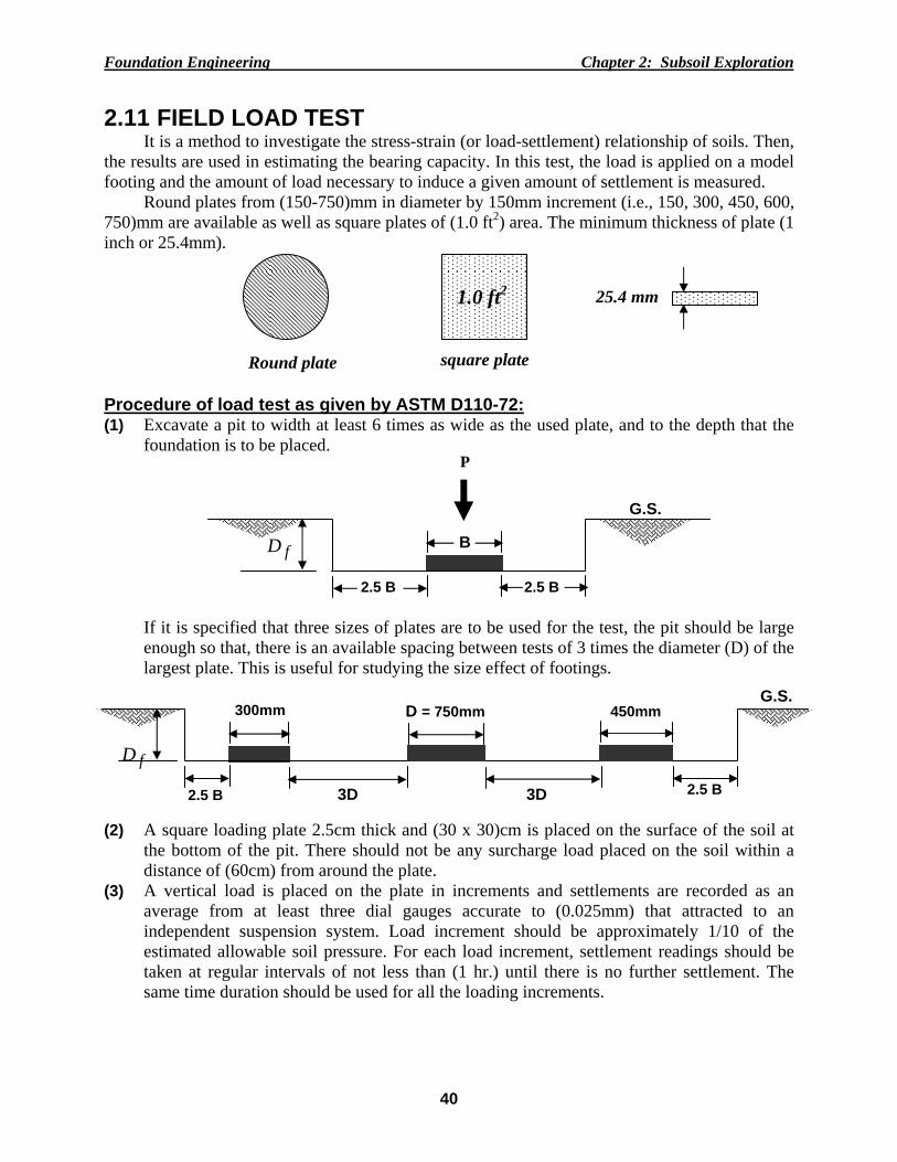
Round plates from (150-750)mm in diameter by 150mm increment (i.e., 150, 300, 450, 600, 750)mm are available as well as square plates of (1.0 ft2) area. The minimum thickness of plate (1 inch or 25.4mm).
Procedure of load test as given by ASTM D110-72: (1) Excavate a pit to width at least 6 times as wide as the used plate, and to the depth that the
foundation is to be placed.
If it is specified that three sizes of plates are to be used for the test, the pit should be large enough so that, there is an available spacing between tests of 3 times the diameter (D) of the largest plate. This is useful for studying the size effect of footings.
(2) A square loading plate 2.5cm thick and (30 x 30)cm is placed on the surface of the soil at the bottom of the pit. There should not be any surcharge load placed on the soil within a distance of (60cm) from around the plate.
(3) A vertical load is placed on the plate in increments and settlements are recorded as an average from at least three dial gauges accurate to (0.025mm) that attracted to an independent suspension system. Load increment should be approximately 1/10 of the estimated allowable soil pressure. For each load increment, settlement readings should be taken at regular intervals of not less than (1 hr.) until there is no further settlement. The same time duration should be used for all the loading increments.
Round plate square plate
1.0 ft2 25.4 mm
P
G.S.
fD
B
2.5 B 2.5 B
G.S.
fD
300mm
2.5 B
D = 750mm 450mm
2.5 B 3D 3D
Foundation Engineering Chapter 2: Subsoil Exploration
41
(4) The test is continued until a settlement of 25mm is observed or until the load increments reached 1.5 times the estimated allowable soil pressure.
(5) If the load is released, the elastic rebound of the soil should be recorded for a periods of time equal to the same time durations of each applied load increment.
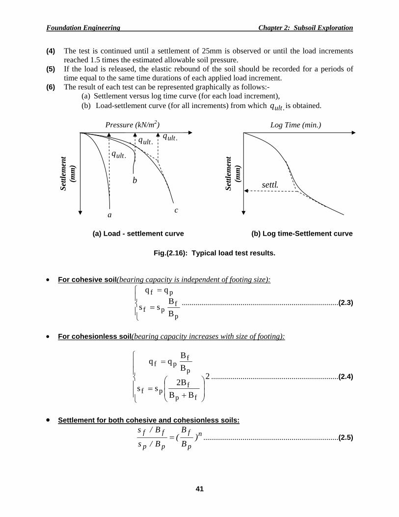
(6) The result of each test can be represented graphically as follows:- (a) Settlement versus log time curve (for each load increment), (b) Load-settlement curve (for all increments) from which .ultq is obtained.
• For cohesive soil(bearing capacity is independent of footing size):
where, V = total load on a bearing area, A = contact area of footing or plate, q = bearing pressure beneath A, P = perimeter of footing or plate, and s = perimeter shear. This method needs data from two-plate load tests so that Eq.(2.6) can be solved for q and s
(for given settlement). After the values of q and s are known, then, the size of a footing required to carry a given load can be calculated. 2.12 FIELD PENETRATION TESTS 2.12.1 DynamicorStandard Penetration Test (SPT)
This test is preferred for very hard deposits, particularly of cohesionless soils for which undisturbed samples cannot easily be obtained. It utilizes a split-spoon sampler shown previously in Fig.(2.7a) that driven into the soil.
The test consists of driving the standard split-barrel sampler of dimensions (680mm length, 30mm inside diameter and 50mm outside diameter) a distance of 460mm (18'') into the soil at the bottom of the boring. This was done by using a 63.5kg (140Ib) driving mass (or hammer) falling "free" from a height of 760mm (30"). Then, counting the number of blows required for driving the sampler the last 305mm (12") to obtain the (N) number (neglecting the no. of blows for the upper first 150mm).
Note: The SPT- value is rejected or halted in any one of the following cases:
(a) if50 blows are required for any 150mm increment, or (b) if100 blows are obtained, or (c) if10 successive blow produce no advance.
Foundation Engineering Chapter 2: Subsoil Exploration
43
The number of blows (N) can be correlated with the relative density ( rD ) of Cohesionless soil (sand) and with the consistency of cohesive soil (clay) as shown in Tables (2.6, and 2.7).
Table (2.6): Relative density of sands according to results of standard penetration test.
SPT- value N/30cm
Relative density
100xee
ee
minmax
insitumaxrD −
−= °φ
0-4 0-15 Very loose 28 4-10 15-35 Loose 28-30 10-30 35-65 Medium 30-36 30-50 65-85 Dense 36-41 > 50 85- 100 Very dense > 41
Table (2.7): Relation of consistency of clay, SPT N-value, and unconfined compressive strength ( uq ).
SPT- value N/30cm consistency )ksf(q u )cm/kg(q 2
u Below Very soft 0-0.5 0-0.25
2-4 Soft 0.5-1 0.25-0.5 4-8 Medium 1-2 0.5-1
8-15 Stiff 2-4 1-2 15-30 Very stiff 4-8 2-4 > 30 Hard > 8 > 4
2.12.2Corrections for N-value
(1) W.T. Correction (in case of presence of W.T.):
For N > 15: )15N(5.015N field.corr −+= .…….…………………………..…(2.7) and
For N ≤ 15: field.corr NN = …….……………..…......……..……………..….(2.8)
• If N‐value is measured above water table, no need for this correction.
(2) Overburden pressure, NC ; Energy ratio, 1η ; Rod length, 2η ; Sampler;
Foundation Engineering Chapter 2: Subsoil Exploration
44
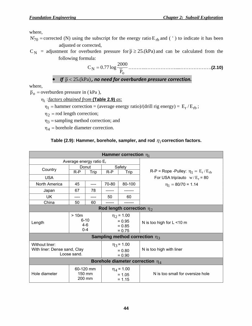
where, =′70N corrected (N) using the subscript for the energy ratio rbE and ( ' ) to indicate it has been
adjusted or corrected, NC = adjustment for overburden pressure for )kPa.(25p ≥ and can be calculated from the
following formula:
oN P
2000log77.0C = ………..………………....……………….(2.10)
• If )kPa.(25p < , no need for overburden pressure correction. where,
=op overburden pressure in ( kPa ), :iη factors obtained from (Table 2.9) as: =η1 hammer correction = (average energy ratio)/(drill rig energy) = rbr E/E ; =η2 rod length correction; =η3 sampling method correction; and =η4 borehole diameter correction.
Table (2.9): Hammer, borehole, sampler, and rod iη correction factors.
Hammer correction 1η Average energy ratio Er
R-P = Rope -Pulley: =η1 rbr E/E
For USA trip/auto rE/w = 80 =η1 80/70 = 1.14
Country Donut Safety R-P Trip R-P Trip
USA North America 45 ---- 70-80 80-100
Japan 67 78 ------ ------- UK ---- ---- 50 60
China 50 60 ------ ------- Rod length correction 2η
Length
> 10m 6-10 4-6 0-4
2η = 1.00 = 0.95 = 0.85 = 0.75
N is too high for L <10 m
Sampling method correction 3η
Without liner: With liner: Dense sand, Clay
Loose sand.
3η = 1.00 = 0.80 = 0.90
N is too high with liner
Borehole diameter correction 4η
Hole diameter 60-120 mm
150 mm 200 mm
4η = 1.00 = 1.05 = 1.15
N is too small for oversize hole
Foundation Engineering Chapter 2: Subsoil Exploration
45
Notes:
1. It is evident that all iη =1.0 for the case of a small borehole, no sampler liner, length of drill rod >10 m and the given drill rig has 70E r = . In this case the only adjustment is for overburden pressure (i.e., Nfield.corr C.NN = ).
2. Large values of rE decrease the blow count (N) linearly (i.e., 12r
1r2 N..
EE
N = ). This
equation is used to convert any energy ratio to any other base.
3. If cm10/blows...10Nfield = , then .cm30/blows...301030.10N .corr =⎟
⎠⎞
⎜⎝⎛=
2.12.3Staticor ConePenetration Test (CPT)
This is a simple static test used for soft clays and fine to medium coarse sands. The test is not applicable in gravels and stiff hard clays. It is performed by pushing the standard cone (according to ASTM D3441 with a 60o point and base diameter = 35.7mm with cross-section area of 10 cm2) into the ground at a rate of (10 – 20) mm/sec.Several cone configurations can be used such as:
1. Mechanical or the earliest "Dutch Cone Type", 2. Electric friction with strain gauges, 3. Electric piezo for pore water measurement, 4. Electric piezo/friction to measure cq , sq and u or (pwp), and 5. Seismic cone to compute dynamic shear modulus. Fig.(2.17b) shows the operations sequence of a mechanical cone as: in position (1) the cone
is seated; position (2) advances the cone tip to measure cq ; position (3) advances the friction sleeve to measure sq ;and position (4) advances both tip and sleeve to measure tq = cq + sq.Therefore, at any required depth, the tip and sleeve friction resistances cq and sq are measured and then used to compute a friction ratio Rf as:
100xqq
(%)fc
sR = ; Rf <1% for sands; Rf >5 or 6% for clays and peat.
The data collected from the CPT can be correlated to establishtheundrained shear strength uS of cohesive soils,allowable bearing capacity of piles, to classify soils; and to estimate rD,..φ
for sands. A typical data set is shown in Fig.(2.18b).
Foundatio
(a) Dutchpoint r
Fig.(2.1
on Engineeri
(a)Piezo
cone modifiedresistance cq a
7): Mechan
ing
ocone.
Fig.(
d to measure and skin frictio
nical (or Dut
(2.18): Elect
both on fq
tch) cone, o
(b)a pr
46
(b) Cone
tric cone an
operations s
Positions of thressure record
C
Penetration r
nd CPT data
sequence, a
he Dutch cone .
Chapter 2: Su
record for cla
a.
and tip resis
during
ubsoil Explor
ay soil.
(c) Typical ou
stance data
ration
tput.
a.
Foundatio
2.13
strength) design of
• A
1. 2. 3. 4.
on Engineeri
VANE
It is a fieof soft to m
f foundations
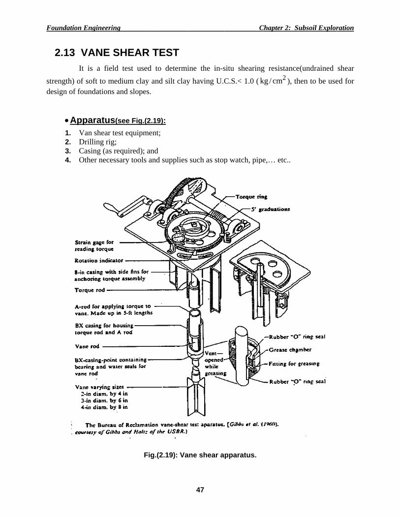
ApparatusVan shear Drilling rigCasing (as Other nece
ing
SHEAR ld test used
medium clay s and slopes
s(see Fig.(2test equipmeg; required); a
essary tools a
Fi
TEST d to determand silt clay
.
2.19): ent;
and and supplies
ig.(2.19): Va
47
mine the in-sy having U.C
s such as stop
ane shear a
C
situ shearingC.S.< 1.0 ( k
p watch, pip
pparatus.
Chapter 2: Su
g resistance2cm/kg ), th
pe,… etc..
ubsoil Explor
(undrained hen to be use
ration
shear ed for
Foundation Engineering Chapter 2: Subsoil Exploration
48
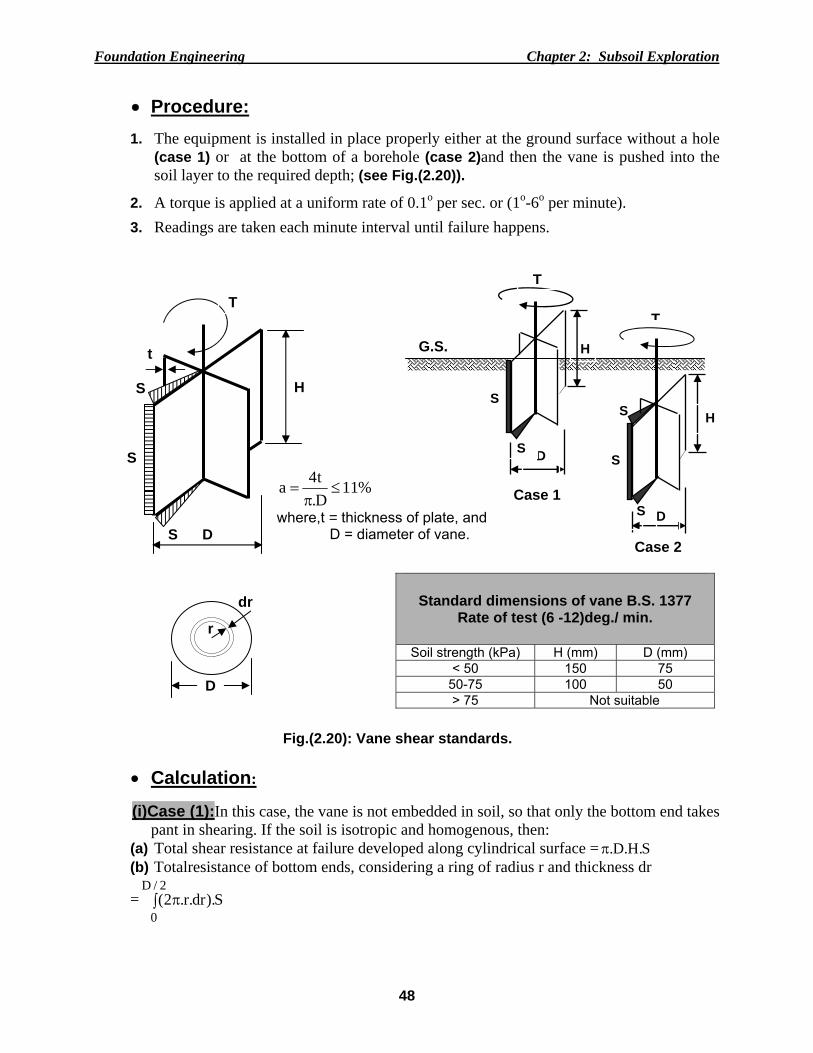
• Procedure: 1. The equipment is installed in place properly either at the ground surface without a hole
(case 1) or at the bottom of a borehole (case 2)and then the vane is pushed into the soil layer to the required depth; (see Fig.(2.20)).
2. A torque is applied at a uniform rate of 0.1o per sec. or (1o-6o per minute).
3. Readings are taken each minute interval until failure happens.
• Calculation: (i)Case (1):In this case, the vane is not embedded in soil, so that only the bottom end takes
pant in shearing. If the soil is isotropic and homogenous, then: (a) Total shear resistance at failure developed along cylindrical surface = S.H.D.π (b) Totalresistance of bottom ends, considering a ring of radius r and thickness dr
= ∫ π2/D
0S).dr.r.2(
Case 1
Case 2
G.S.
S
H
D
S
S
T
Fig.(2.20): Vane shear standards.
D
r
dr
Standard dimensions of vane B.S. 1377 Rate of test (6 -12)deg./ min.
Soil strength (kPa) H (mm) D (mm)
< 50 150 75 50-75 100 50 > 75 Not suitable
%11D.t4a ≤
π=
where,t = thickness of plate, and D = diameter of vane.
H
D
S
S
S
t H
D
S
S
TT
Foundatio
(c)
or T
(ii)
or T
Notes: • U• It
T
where,λ
Aef
λ
(a) Bjerr[(Bje
on Engineeri
The torque
(2
SD.T u2π
=
Case (2): Itop and bott
(2
SD.T u2π
=
Use consisten is found thherefore, Bj
is a correcAlso, Aas et ffects of agin
rum correctionerrum, 1972) a
ing
T at failure w
)6DH( + ……
If the top endtom ends:
)3DH( + ……
nt units, suchhat the uS errum's (19
designu ,S
ction factor al. (1986) p
ng and OCR
Ip ,%
n factor for vanand Ladd etal.,
Fig.(2.
will then equ
………………
d of the vane
………………
h as: T in (kgvalues obta
972) propose
fieldu ,S..λ=
depends onproposed anoR (Overconso
ne‐shear test. 1977)].
21): Vane s
49
ual: π= D.(T
……….……
e is also emb
………….…
g-cm); uS inained by va
ed a reductio
d ……………
n plasticity iother charts olidation rati
λ
Ip ,%
(b) Rein (Aas et
shear correc
C
+2D)S.H.D
D
……..………
bedded in so
……..………
n (kg/cm2);aane shear teon factor usin
…………….
index pI and(see Fig.(2.io).
Vane st
nterpretation oal. (1986) to i
ction factor
Chapter 2: Su
∫ π2/D
0S).dr.r.2(
..……(2.11)
oil, so sheari
..……(2.12)
and H and D est are too ng the follow
.………..……
d obtained f21b)) taking
rength ratio
of the Bjerrumnclude effects
r λ .
ubsoil Explor
r.
)
ng takesplac
)
in (cm). large for de
wing formula
……..……(2
from Fig.(2.g into accoun
o Su, v /P o
chart of part of aging and O
ration
ce on
esign. a:
2.13)
.21a); nt the
a byOCR ).
Foundation Engineering Chapter 2: Subsoil Exploration
50
SOLVED PROBLEMS Problem (2.1):A thin-walled tube (OD = 76.2mm, ID = 73mm) was pushed into a soft clay at
the bottom of a borehole a distance of 600mm. When the sampler was recovered a measurement done inside the tube indicated a recovered sample length of 575mm. Calculate the recovery and area ratios.
Solution:
Recovery ratio: 958.0600575Lr ==
Area ratio: %96.8100x)73(
)73()2.76(A2
22r =
−=
Problem (2.2):A three storysteel frame office building will be built on a site where the soils are
expected to be of average quality and uniformity. The building will have a (30m x 40m) footprint and is expected to be supported on spread footing foundations located about (1m) below the ground surface. The site appears to be in its natural condition, with no evidence of previous grading. Bedrock is several hundred feet below the ground surface. Determine the required number and depth of the borings.
Solution:
• Number of borings: From Table (2.5), one boring will be needed for every 200 to 400 m2 of footprint area. Since the total footprint area is 30 x 40 =1200 m2, use (4)four borings. • Depth of borings: For subsurface condition of average quality, the minimum depth is:
=+=+ 1355 7070 .f
. )(DS. 12m. However, it would be good to drill at least one of the borings to a slightly greater depth to check lower strata.In summary, the exploration plan will be 4 borings with, 3 borings to 12 m, and 1 boring to 16 m.
Problem (2.3):Given:Available information about:
Structure: Multistory building with 3 stories and basement
No. of columns = 16, Column load = 1000 kN
Raft dimensions: 16m x 16m x 1m, Foundation at 3m below G.S.
Foundation Engineering Chapter 2: Subsoil Exploration
51
Solution:
• Number and layout of borings: From Table (2.4b), for poor quality and/or erratic subsurface conditions, one boring is needed
for every (100 to 300) m2 of footprint area. Since the total footprint area is 16x16=256m2>
200m2 (average value), use one or two borings.
• Depth of borings:
(a) m)(.d 241651 ==
(b) 10% of contact pressure:
kPa...))(())((
))()(().(qcontact 5381631616
1161624100016=−
+=
,)d(
))((.)..(. 216161653853810
+= .………………..….………..……d = 34.6m
(c) 5% of overburden pressure:
,)d(
))((.)])(d()(.[. 216161653810203616050
+=−−+ …………...d = 15.5m
From (b and c) take the smaller d = 15.5m
(d) m83.15)4.(6S.6d 7.07.0 ===
From all (24m, 15.5m, and 1٥.٨٣m) take the larger d = 24m
∴ =+= 324D...use 27m from G.S.
Problem(2.4): A wide strip footing applying net pressure of 35 kPa is to be constructed 1m below the surface of uniform soil having unit weight of 19 kN/m3. The footing is 5m wide and the water table is at ground surface. Is 12m depth of boring (measured from ground surface) sufficient for subsoil exploration program.
Solution:
(a) m)()B(d 15533 ===
(b)10% of contact pressure: m.d..............,.........)d)(d(
))()(().(. 3415
15353510 =++
=
(c) 5% of overburden pressure: m.d..,.........)d)(d(
))()(()d(. 2515
153599050 =++
=+
From (b and c) take the smaller d = 4.3m
Foundation Engineering Chapter 2: Subsoil Exploration
52
From all(15m, and 4.3m) take the larger d =15m, and so the depth from ground surface
=+= 115D 16m, ∴12m is not sufficient.
Problem (2.5):A standard penetration test SPT has been conducted in a coarse sand to a
depth of 4.8m below the ground surface. The blow counts obtained in the field were as follows: 0 – 6 in: 4 blows; 6 -12 in: 6 blows; 12 -18 in: 8 blows. The test was conducted using a USA-style donut hammer in a 150mm diameter boring with a standard sampler and liner. If the vertical effective stress at the test depth was 70 kN/m2, determine 60N′ ?
Solution:
The raw SPT value isN = 6 + 8 = 14
Since kPa...po 70=′ > 25 kPa∴ 12170
2000770 10 .log..CN ==
From (Table 2.9): ==η rbr E/E1 45/60 = 0.75
2η =0.85(forL = 4.8m (rod length)< 6m),
3η = 0.90 (for loose sand with liner),
4η =1.05 (for B.H. diameter = 150mm),
432160 ηηηη=′ ........C..NN Nfield = 14(1.12)(0.75)(0.85)(0.90)(1.05) =10blows Problem (2.6):A standard penetration test was carried out in sand at 5m depth below the
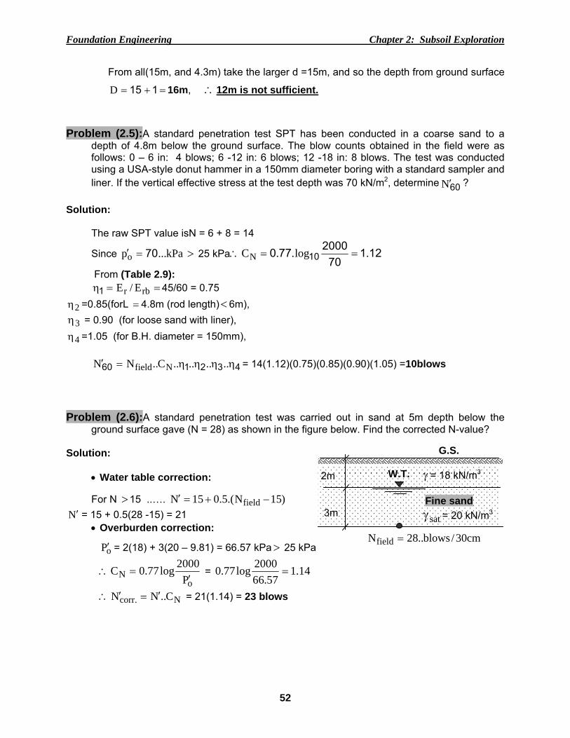
ground surface gave (N = 28) as shown in the figure below. Find the corrected N-value?
Solution:
• Water table correction: For N >15 ..…. )15N.(5.015N field −+=′
Foundation Engineering Chapter 2: Subsoil Exploration
53
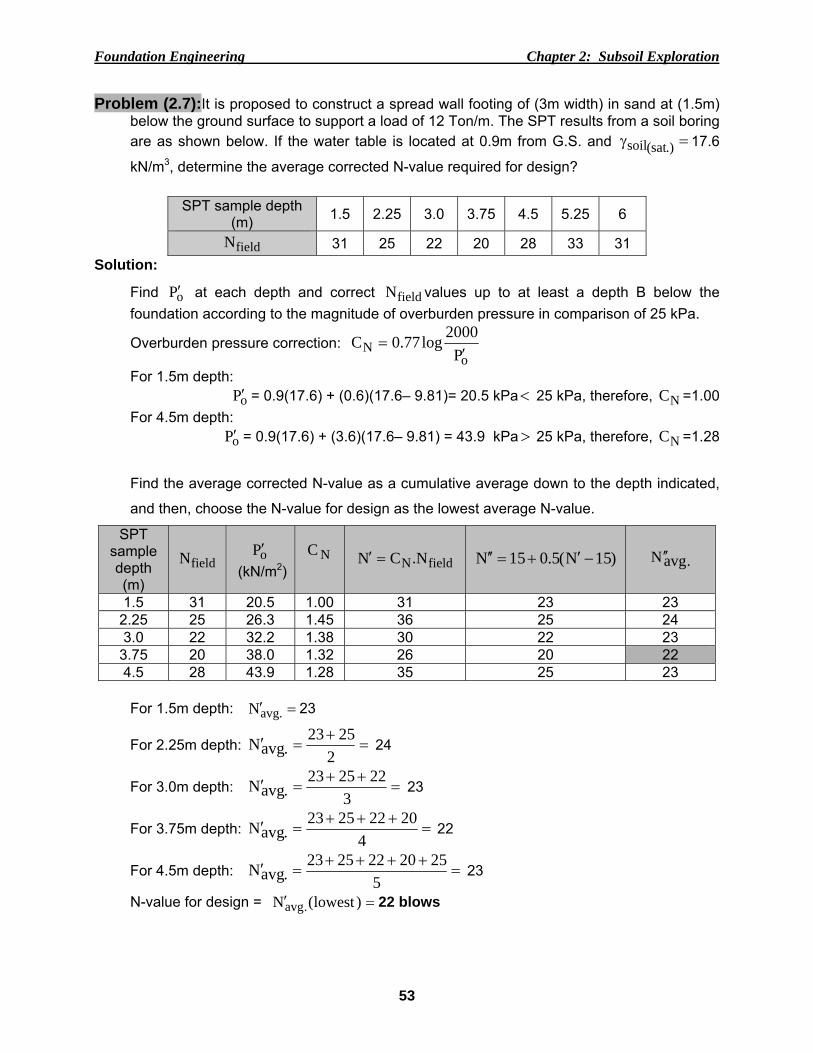
Problem (2.7):It is proposed to construct a spread wall footing of (3m width) in sand at (1.5m) below the ground surface to support a load of 12 Ton/m. The SPT results from a soil boring are as shown below. If the water table is located at 0.9m from G.S. and =γ .)sat(soil 17.6
kN/m3, determine the average corrected N-value required for design?
SPT sample depth (m) 1.5 2.25 3.0 3.75 4.5 5.25 6
fieldN 31 25 22 20 28 33 31 Solution:
Find oP′ at each depth and correct fieldN values up to at least a depth B below the foundation according to the magnitude of overburden pressure in comparison of 25 kPa.
Foundation Engineering Chapter 2: Subsoil Exploration
54
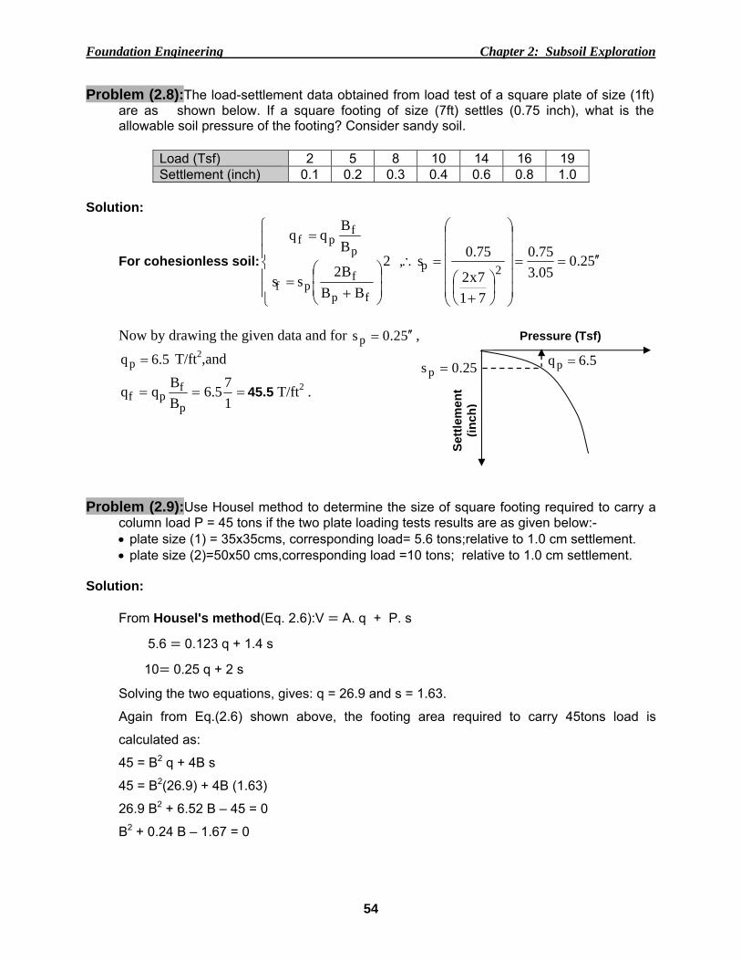
Problem (2.8):The load-settlement data obtained from load test of a square plate of size (1ft) are as shown below. If a square footing of size (7ft) settles (0.75 inch), what is the allowable soil pressure of the footing? Consider sandy soil.
Now by drawing the given data and for 52.0sp ′′= ,
5.6qp = T/ft2,and
===175.6
BBqq
p
fpf 45.5 T/ft2 .
Problem (2.9):Use Housel method to determine the size of square footing required to carry a
column load P = 45 tons if the two plate loading tests results are as given below:- • plate size (1) = 35x35cms, corresponding load= 5.6 tons;relative to 1.0 cm settlement. • plate size (2)=50x50 cms,corresponding load =10 tons; relative to 1.0 cm settlement.
Solution:
From Housel's method(Eq. 2.6):V A. q + P. s
5.6 0.123 q + 1.4 s
10 0.25 q + 2 s
Solving the two equations, gives: q = 26.9 and s = 1.63.
Again from Eq.(2.6) shown above, the footing area required to carry 45tons load is
calculated as:
45 = B2 q + 4B s
45 = B2(26.9) + 4B (1.63)
26.9 B2 + 6.52 B – 45 = 0
B2 + 0.24 B – 1.67 = 0
Settl
emen
t (in
ch)
Pressure (Tsf)
25.0s p = 5.6qp =
Foundation Engineering Chapter 2: Subsoil Exploration
55
18.12
59.224.0)1)(2(
)67.1)(1)(1(4)24.0(24.0B
2=
±−=
+±−= m
Take the footing 1.20 m x 1.20 m.
Problem (2.10):A vane tester with a diameter d = 9.1cms and a height h = 18.2 cms requires a
torque of 110 N-m to shear a clay soil sample, with a plasticity index of 48%. Find the soil
un-drained cohesion uS ?
Solution: For CASE (2) with top and bottom vane ends embedded in soil, the torque is given by:
)DH(,S.D.T fieldu32
2+
π=
or 40
309101820
20910
1100
32
22=
⎥⎦⎤
⎢⎣⎡ +
π=
+π
=..)..(
.
)DH(D.
T,S fieldu kN/m2
From Fig.(2.27a) for a plasticity index of 48%, Bjerrum'scorrection factor λ = 0.80, and