1 2100 ELECTRICAL SAFETY PROGRAM Document History Version Date Comments 0.1 For Internal Review 1.0 May 13, 2016 Final Version This document will be reviewed routinely and updated with changes as needed. Departments listed as having roles and responsibilities are provided an updated version of this document upon revision. Table of Contents ELECTRICAL SAFETY PROGRAM........................................................................................................... 1 Document History ..................................................................................................................................... 1 2. Scope ................................................................................................................................................. 3 3. Definitions ......................................................................................................................................... 3 4. Responsibilities .................................................................................................................................. 5 4.1. University of Virginia Facilities Management – Occupational Health and Safety (FM-OHS)........... 5 4.2. Supervisors................................................................................................................................. 6 5. Procedure........................................................................................................................................... 6 6. Governmental Standards .................................................................................................................... 6 7. Employee Training............................................................................................................................. 7 7.1. Retraining................................................................................................................................... 7 7.2. Qualified Person ........................................................................................................................ 7 7.3. Unqualified Person..................................................................................................................... 7 7.4. Emergency Procedures Training................................................................................................. 7 7.5. Training Documentation ............................................................................................................ 7 8. Risk Assessment Procedure ................................................................................................................ 8 9. Job Briefing........................................................................................................................................ 8 10. Establishing an Electrically Safe Work Condition (LOTO) ............................................................. 8 10.1. Process to Establish an Electrically Safe Work Condition ........................................................... 8 11. Approach Boundaries to Live Parts ................................................................................................ 9 11.1. Limited Approach Boundary ...................................................................................................... 9
Transcript
1
2100 ELECTRICAL SAFETY PROGRAM
Document History Version Date Comments 0.1 For Internal Review 1.0 May 13, 2016 Final Version
This document will be reviewed routinely and updated with changes as needed. Departments listed as having roles and responsibilities are provided an updated version of this document upon revision.
Table of Contents ELECTRICAL SAFETY PROGRAM ........................................................................................................... 1
Document History ..................................................................................................................................... 1
Appendix A .............................................................................................................................................. 22
Appendix B .............................................................................................................................................. 23
Appendix C .............................................................................................................................................. 26
Appendix D ............................................................................................................................................. 27
Appendix E .............................................................................................................................................. 28
Appendix F .............................................................................................................................................. 29
1. Purpose
The purpose of this Electrical Safety Program is to provide electrical safety procedures for those University of Virginia Facilities Management employees that may work on, or near, electrical systems. In addition to providing for employee safety, this document will contribute to the protection of University of Virginia equipment and continuity of operations.
2. Scope This Program applies to all University of Virginia employees that perform maintenance, testing or any other task on, or near, electrical systems. This includes work that may be performed on energized conductors or circuit parts.
3. Definitions “Alternating current (AC)” – a flow of electrons which regularly reverses its direction of flow. “AED” - Automatic External Defibrillator. A portable defibrillator designed to be automated such that it can be used by persons without substantial medical training who are responding to a cardiac emergency. “Arc” - is an electrical discharge generated when two energized conductors are separated, causing a buildup of heat and gas to cross the gap. “Arc Flash Protection” – the maximum incident energy resistance demonstrated by a material (or a layered system of materials) prior to degradation or at the onset of a second-degree skin burn. Arc rating is normally expressed in cal/cm2. “Battery” – a DC electrical power source composed of two or more chemical cells. “CPR” - Cardiopulmonary resuscitation. An emergency lifesaving procedure that is done when someone's breathing or heartbeat has stopped. This may happen after an electric shock, heart attack, or drowning. CPR combines rescue breathing and chest compressions. “De-energized” – free from any electrical connection to a source of potential difference and from electrical charge.
4
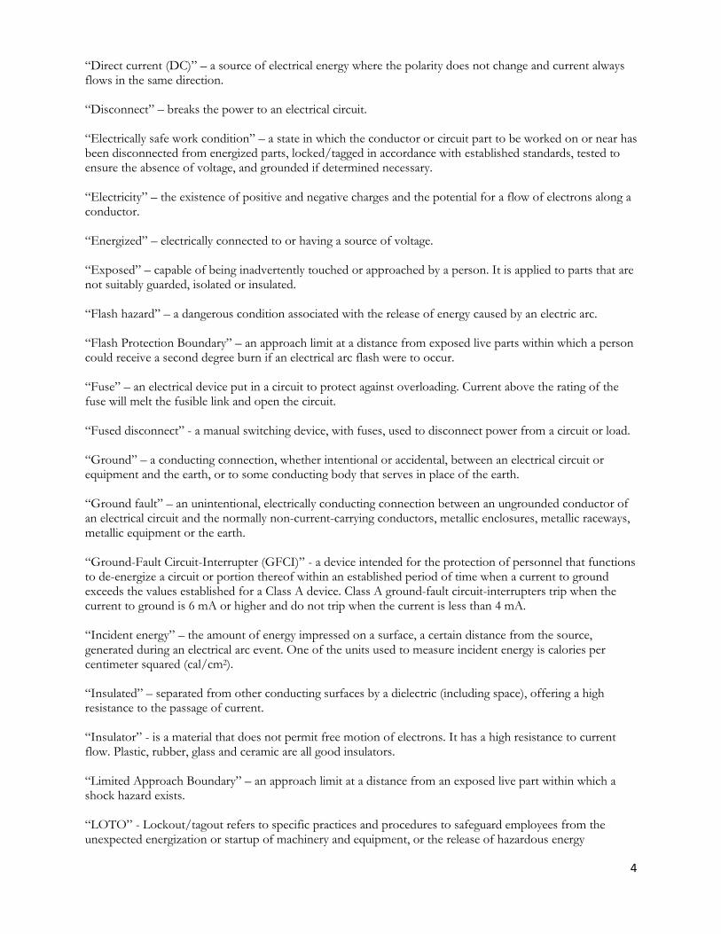
“Direct current (DC)” – a source of electrical energy where the polarity does not change and current always flows in the same direction. “Disconnect” – breaks the power to an electrical circuit. “Electrically safe work condition” – a state in which the conductor or circuit part to be worked on or near has been disconnected from energized parts, locked/tagged in accordance with established standards, tested to ensure the absence of voltage, and grounded if determined necessary. “Electricity” – the existence of positive and negative charges and the potential for a flow of electrons along a conductor. “Energized” – electrically connected to or having a source of voltage. “Exposed” – capable of being inadvertently touched or approached by a person. It is applied to parts that are not suitably guarded, isolated or insulated. “Flash hazard” – a dangerous condition associated with the release of energy caused by an electric arc. “Flash Protection Boundary” – an approach limit at a distance from exposed live parts within which a person could receive a second degree burn if an electrical arc flash were to occur. “Fuse” – an electrical device put in a circuit to protect against overloading. Current above the rating of the fuse will melt the fusible link and open the circuit. “Fused disconnect” - a manual switching device, with fuses, used to disconnect power from a circuit or load. “Ground” – a conducting connection, whether intentional or accidental, between an electrical circuit or equipment and the earth, or to some conducting body that serves in place of the earth. “Ground fault” – an unintentional, electrically conducting connection between an ungrounded conductor of an electrical circuit and the normally non-current-carrying conductors, metallic enclosures, metallic raceways, metallic equipment or the earth. “Ground-Fault Circuit-Interrupter (GFCI)” - a device intended for the protection of personnel that functions to de-energize a circuit or portion thereof within an established period of time when a current to ground exceeds the values established for a Class A device. Class A ground-fault circuit-interrupters trip when the current to ground is 6 mA or higher and do not trip when the current is less than 4 mA. “Incident energy” – the amount of energy impressed on a surface, a certain distance from the source, generated during an electrical arc event. One of the units used to measure incident energy is calories per centimeter squared (cal/cm2). “Insulated” – separated from other conducting surfaces by a dielectric (including space), offering a high resistance to the passage of current. “Insulator” - is a material that does not permit free motion of electrons. It has a high resistance to current flow. Plastic, rubber, glass and ceramic are all good insulators. “Limited Approach Boundary” – an approach limit at a distance from an exposed live part within which a shock hazard exists. “LOTO” - Lockout/tagout refers to specific practices and procedures to safeguard employees from the unexpected energization or startup of machinery and equipment, or the release of hazardous energy
5
“Multimeter” – an instrument that can measure different values such as voltage, current and resistance. “Overcurrent” – any current in excess of the rated current of equipment or the ampacity of a conductor. It may result from overload, short circuit or ground fault. “Panelboard” – a single panel or group of panel units designed for assembly in the form of a single panel, including buses and automatic overcurrent devices, and equipment with or without switches for the control of light, heat or power circuits. “PPE” - Personal protective equipment (PPE) refers to protective clothing, helmets, goggles, or other garments or equipment designed to protect the wearer's body from injury or infection. “Qualified person” – one who has skills and knowledge related to the construction and operation of the electrical equipment and installations and has received safety training to recognize and avoid the hazards involved. “Resistance” – the quality of a material to oppose current flow. “Restricted Approach Boundary” – an approach limit at a distance from an exposed live part within which there is an increased risk of shock, due to electrical arc over combined with inadvertent movement, for personnel working in close proximity to the live part. “Shock hazard” – a dangerous condition associated with the possible release of energy caused by contact or approach to live parts. “Short circuit” – a condition, usually undesirable, where conductors make contact in such a way that current flows through a contact rather than through the intended path. “Switch” – an electrical device that opens and closes circuits. The simplest switches either turn a circuit on or off. “Switchboard” – a large single panel, frame, or assembly of panels on which are mounted on the face, back or both, switches, overcurrent and other protective devices, buses and instruments. “Terminal” – a point of electrical connection. “Transformer”– a device that transforms voltage, current and impedance levels through the interaction of magnetic fields between two coils of wires. Energy is usually applied to the primary windings, and the transformed result is taken from the secondary windings. “Unqualified Person” – a person who is not a qualified person and is not allowed to work on energized electrical equipment.
4. Responsibilities 4.1. University of Virginia Facilities Management – Occupational Health and Safety (FM-
OHS) It is the responsibility of FM-OHS to arrange training related to electrical safety as well as to supervise the selection of personal protective equipment (PPE) and insulated tools associated with electrical safety. Further, FM-OHS will audit yearly this Program and will electronically receive and maintain energized electrical work permits.
6
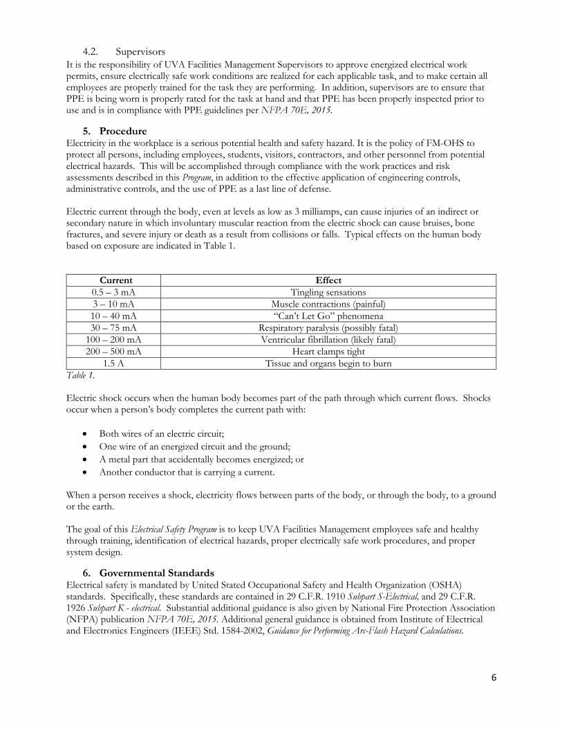
4.2. Supervisors It is the responsibility of UVA Facilities Management Supervisors to approve energized electrical work permits, ensure electrically safe work conditions are realized for each applicable task, and to make certain all employees are properly trained for the task they are performing. In addition, supervisors are to ensure that PPE is being worn is properly rated for the task at hand and that PPE has been properly inspected prior to use and is in compliance with PPE guidelines per NFPA 70E, 2015.
5. Procedure Electricity in the workplace is a serious potential health and safety hazard. It is the policy of FM-OHS to protect all persons, including employees, students, visitors, contractors, and other personnel from potential electrical hazards. This will be accomplished through compliance with the work practices and risk assessments described in this Program, in addition to the effective application of engineering controls, administrative controls, and the use of PPE as a last line of defense. Electric current through the body, even at levels as low as 3 milliamps, can cause injuries of an indirect or secondary nature in which involuntary muscular reaction from the electric shock can cause bruises, bone fractures, and severe injury or death as a result from collisions or falls. Typical effects on the human body based on exposure are indicated in Table 1.
Current Effect 0.5 – 3 mA Tingling sensations 3 – 10 mA Muscle contractions (painful) 10 – 40 mA “Can’t Let Go” phenomena 30 – 75 mA Respiratory paralysis (possibly fatal)
100 – 200 mA Ventricular fibrillation (likely fatal) 200 – 500 mA Heart clamps tight
1.5 A Tissue and organs begin to burn Table 1. Electric shock occurs when the human body becomes part of the path through which current flows. Shocks occur when a person’s body completes the current path with:
• Both wires of an electric circuit; • One wire of an energized circuit and the ground; • A metal part that accidentally becomes energized; or • Another conductor that is carrying a current.
When a person receives a shock, electricity flows between parts of the body, or through the body, to a ground or the earth. The goal of this Electrical Safety Program is to keep UVA Facilities Management employees safe and healthy through training, identification of electrical hazards, proper electrically safe work procedures, and proper system design.
6. Governmental Standards Electrical safety is mandated by United Stated Occupational Safety and Health Organization (OSHA) standards. Specifically, these standards are contained in 29 C.F.R. 1910 Subpart S-Electrical, and 29 C.F.R. 1926 Subpart K - electrical. Substantial additional guidance is also given by National Fire Protection Association (NFPA) publication NFPA 70E, 2015. Additional general guidance is obtained from Institute of Electrical and Electronics Engineers (IEEE) Std. 1584-2002, Guidance for Performing Arc-Flash Hazard Calculations.
7
7. Employee Training A training program will be provided for each employee who may be exposed to electrical hazards. This training will allow employees to be able to identify hazards and apply safe electrical work procedures when applicable. Records of this training will be maintained by FM-OHS.
7.1. Retraining An employee shall receive retraining under any of the following conditions:
• If a Supervisor or annual FM-OHS audit indicate that an employee is not complying with established
safety-related work practices. • If new technology, new types of equipment, or changes in procedures necessitate the use of safety-
related work practices that are different from those that an employee would normally use. • If safety-related work practices must be performed that are not normally used during the employee’s
regular job duties.
7.2. Qualified Person A Qualified Person is an employee who has demonstrated an ability to perform duties safely at his or her level of training, has skills related to the construction and operation of electrical equipment and installations, and has received safety training on the hazards involved. Specifically, this employee shall receive training that allows that employee to:
• Recognize and avoid electrical hazards inherent in electrical equipment and systems; • Be familiar with the proper use of special precautionary techniques, PPE, insulating and shielding
materials, and insulated tools and test equipment; • Possess the skills and techniques necessary to distinguish exposed energized electrical conductors and
circuit parts from other parts of electrical equipment; most often a licensed electrician. • Possess the skills and techniques necessary to determine the nominal voltage of exposed electrical
conductors and circuit parts; • Be able to understand and implement the approach distances specified in Table 1 and Table 2 of this
document and the corresponding voltages to which the qualified person will be exposed; • Be able to understand and implement the decision-making process necessary to determine the degree
and extent of the hazard and the personal protective equipment and job planning necessary to perform the task safely.
7.3. Unqualified Person An Unqualified Person is an employee permitted to work within the Limited Approach Boundary of exposed energized electrical conductors and circuit parts operating at 50 volts or more but that does not have the level of training to be considered qualified as defined by this document. These employees shall be trained to:
• Become familiar with any of the electrical safety-related practices that are necessary for their safety.
7.4. Emergency Procedures Training Employees exposed to shock hazards shall be trained in CPR/AED and First Aid procedures upon initial assignment and every two years thereafter. It is the responsibility of FM-OHS to ensure that CPR/AED and First Aid refresher training is current. Employees will also be trained in methods of release of victims from contact with exposed electrical conductors or circuit parts. Refresher training is to be given annually.
7.5. Training Documentation FM-OHS shall document that each employee has received training as indicated in this document. This documentation shall be made when the employee demonstrates proficiency in the work practices involved and shall be maintained for the duration employment. The documentation should contain each employee’s name and dates of training.
8
8. Risk Assessment Procedure A proper risk assessment of electrical hazards is a vital step to ensure the health and safety of those working with electricity and will reduce the likelihood of injury. Risk assessment is a process of discrete steps intended to ensure that hazards are properly identified and analyzed with regard to their severity and the likelihood of their occurrence. Once hazards have been identified and analyzed, the risk associated with those hazards can be estimated and appropriate protective measures can be implemented with proper follow up to ensure a given control’s effectiveness. Risk assessment includes a comprehensive review of the hazards, the associated foreseeable tasks, and the protective measures that are required in order to maintain an acceptable level of risk, including the following:
• Identifying and analyzing electrical hazards; • Identifying tasks to be performed; • Documenting hazards associated with each task; • Estimating the risk for each hazard/task pair; • Determining the appropriate protective measures needed to adequately reduce the level of risk.
The diagram in Appendix A indicates a proper risk assessment process. A properly performed Job Hazard Analysis (JHA) conducted prior to the start of a task involving potential exposure to electricity will ensure that all facets of risk assessment have been considered and appropriate controls have been implemented.
9. Job Briefing Prior to commencing work, Supervisors shall conduct a job briefing with all employees that have a potential for exposure to energized electrical parts. The briefing should cover the following:
• Hazards associated with the task. This includes identifying shock exposures and arc flash hazards; • Work procedures; • Special precautions such as draining capacitors and gradient potential issues; • Energy source controls (LOTO points); • PPE; • Emergency Response Procedures.
10. Establishing an Electrically Safe Work Condition (LOTO) An electrically safe work condition shall be achieved when performed in accordance with University Lockout/Tagout (LOTO) procedures and verified by the process indicated below. Only qualified persons can establish an electrically safe condition. The process of establishing an electrically safe work condition is inherently hazardous because it requires qualified persons to work around live conductors. Appropriate PPE must be worn and used when performing some of the steps listed below. Electrical conductors and equipment are considered energized until the process of establishing an electrically safe work condition is complete.
10.1. Process to Establish an Electrically Safe Work Condition 1. Determine all sources of electrical supply to the specific equipment. Check applicable up-to-date
drawings, diagrams, and identification tags. a. Most electrical equipment has a single source of supply; however, there are instances where
there are multiple sources, such as rooftop photovoltaic arrays or emergency generators. 2. After properly interrupting the load current, open the disconnecting device(s) for each source.
a. Fuses aren’t considered disconnecting means and a circuit cannot be de-energized by removing one or more fuses. However, a pullout block or safety switch with fuses can be considered a disconnect.
b. Attachment plugs of electric appliances are permitted to be used as disconnects. 3. Wherever possible, visually verify that all blades of the disconnecting devices are fully open or that
drawout-type circuit breakers are withdrawn to the fully disconnected position.
9
a. Sometimes it’s impossible to visually verify the presence of an air gap. In these cases, test for the presence of voltage to verify that the circuit has been fully disconnected.
4. Apply LOTO devices in accordance with University procedures. 5. Use an adequately rated test instrument to test each phase conductor or circuit part to verify it is de-
energized. Test each phase conductor or circuit part to both phase-to-phase, neutral-to-ground and phase-to-ground. Before and after each testing, determine that the test instrument is operating properly through verification on a known voltage source.
6. Discharge stored electrical energy and install safety grounds where necessary. Once these steps have been completed, electrical energy has been removed from all conductors and equipment and cannot reappear unexpectedly. Only under these circumstances is PPE not needed and unqualified persons can perform work on or near electrical equipment.
11. Approach Boundaries to Live Parts A shock risk assessment shall determine the voltage to which personnel have the potential to be exposed, the boundary requirements, and the PPE necessary to protect employees. Shock protection boundaries are identified as limited approach boundary and restricted approach boundary. These boundaries are applicable where approaching personnel are exposed to energized electrical conductors or circuit parts.
11.1. Limited Approach Boundary 11.1.1. Approach by Unqualified Persons
No unqualified person is permitted to approach nearer than the limited approach boundary of energized electrical conductors or live parts.
11.1.2. Unqualified Persons Working at or Close to the Limited Approach Boundary It is the responsibility of the designated person in charge of the work space where the electrical hazard exists to advise the unqualified person(s) of the hazard and warn them to stay outside of the limited approach boundary.
11.1.3. Entering the Limited Approach Boundary In the event there is a need for an unqualified person to cross the limited approach boundary, a qualified person shall advise him or her of the possible hazards and continuously escort the unqualified person while inside the limited approach boundary. There is no scenario where the escorted unqualified person shall cross the restricted approach boundary
11.2. Restricted Approach Boundary No qualified person shall approach or take a conductive object closer to exposed energized electrical conductors or circuit parts operating at 50 volts or more than the restricted approach boundary set forth in Table 2 and Table 3 of this document, unless one of the following apply:
• The qualified person is guarded or insulated from energized electrical conductors or circuit parts operating at 50 volts or more through adequate PPE as determined by an incident energy analysis or PPE Tables Method.
• The energized electrical conductors or circuit part operating at 50 volts or more are PPE insulated from the qualified person and from any other conductive object.
• The qualified person is insulated from any other conductive object.
Approach Boundaries for Shock Protection for Alternating Currents (AC) Limited Approach Boundary
Nominal Potential Difference
Exposed Movable Conductor
Exposed Fixed Circuit Part
Restricted Approach Boundary
<50V Not specified Not specified Not Specified 50V-150V 10 ft 0 in. 3 ft 6 in. Avoid contact 151V-750V 10 ft 0 in. 3 ft 6 in. 1 ft 0 in. 751V-15kV 10 ft 0 in. 5 ft 0 in. 2 ft 2 in.
15.1 kV- 36kV 10 ft 0 in. 6 ft 0 in. 2 ft 7 in. 36.1kV-46kV 10 ft 0 in. 8 ft 0 in. 2 ft 9 in.
46.1kV-72.5kV 10 ft 0 in. 8 ft 0 in. 3 ft 3 in. 72.6kV-121kV 10 ft 8 in. 8 ft 0 in. 3 ft 4 in. 138kV-145kV 11 ft 0 in. 10 ft 0 in. 3 ft 10 in. 161kV-169kV 11 ft 8 in. 11 ft 8 in. 4 ft 3 in. 230kV-242kV 13 ft 0 in. 13 ft 0 in. 5 ft 8 in. 345kV-362kV 15 ft 4 in. 15 ft 4 in. 9 ft 2 in. 500kV-550kV 19 ft 0 in. 19 ft 0 in. 11 ft 10 in. 765kV-800kV 23 ft 9 in. 23 ft 9 in. 15 ft 11 in.
Source: NFPA 70E, 2015 Table 130.4 D (a) Table 2 (All dimensions are distance from energized electrical conductor to employee).
11
Approach Boundaries for Shock Protection for Direct Currents (DC) Limited Approach Boundary
Nominal Potential Difference
Exposed Movable Conductor
Exposed Fixed Circuit Part
Restricted Approach Boundary
<100V Not specified Not specified Not Specified 100V-300V 10 ft 0 in. 3 ft 6 in. Avoid contact 301V-1kV 10 ft 0 in. 3 ft 6 in. 1 ft 0 in. 1.1kV-5kV 10 ft 0 in. 5 ft 0 in. 1 ft 5 in. 5kV- 15kV 10 ft 0 in. 5 ft 0 in. 2 ft 2 in.
15.1kV-45kV 10 ft 0 in. 8 ft 0 in. 2 ft 9 in. 45.1kV-75kV 10 ft 0 in. 8 ft 0 in. 3 ft 2 in. 75.1kV-150kV 10 ft 8 in. 10 ft 0 in. 4 ft 0 in. 150.1kV-250kV 11 ft 8 in. 11 ft 8 in. 5 ft 3 in. 250.1kV-500kV 20 ft 0 in. 20 ft 0 in. 11 ft 6 in. 500.1kV-800kV 26 ft 0 in. 26 ft 0 in. 16 ft 5 in.
Source: NFPA 70E, 2015, Table 130.4 D(b) Table 3 (All dimensions are distance from energized electrical conductor to employee).
12. Arc Flash Arc flash is a phenomenon that is the result of an electric current leaving its intended path and travelling through the air from one conductor to another, or to the ground. The results of an arc flash are often violent and when workers are in close proximity to the arc flash, serious injury or death will occur.
12.1. Arc Flash Risk Assessment An arc flash risk assessment should be done before a person approaches any exposed electrical conductor or circuit part not placed in an electrically safe work condition. This arc flash risk assessment will determine whether an arc flash hazard exists and, if so, the risk assessment shall determine:
• Appropriate safety-related work practices • The arc flash boundary • Required PPE to be used within the arc flash boundary
Arc flash risk assessments shall be updated when a major system modification occurs. The interval between document review is not to exceed a period of 5 years. The results of an Arc flash risk assessment must be documented and maintained.
12.2. Arc Flash Boundary The Arc Flash Boundary is the furthest established boundary from the energy source where, if an arc flash occurred, a worker would be exposed to a curable second degree burn. Employees crossing into the arc flash boundary are required to wear the appropriate PPE as determined by the Incident Energy Analysis Method as published in NFPA 70E, 2015 or the PPE Tables Method that utilize Table 130.7 (C)(15)(A)(a) in NFPA 70E, 2015. A copy of this table is located in Appendix 2 of this document Only a Professional Engineer or other individual specifically qualified through education and experience shall conduct an Incident Energy Analysis that would be used to determine PPE requirements. The Table Method may only be used if the specific task to be performed appears in the tables and the system meets the listed criteria for short circuit magnitude and speed of response of circuit protection. If help is needed with arc flash hazard evaluation process, please email [email protected] or [email protected]
13. Working on or Near Live Electrical Parts When intentionally working within the Restricted Approach Boundary or the Arc Flash Boundary of exposed energized electrical conductors or circuit parts that are not placed in an electrically safe work condition, work to be performed is considered energized electrical work and must be performed by written permit only. In the rare situation when energized equipment cannot be de-energized (or when working in near proximity to energized equipment), the following work practices must be observed to provide protection:
• Obtain Energized Electrical Work Permit; • Unqualified Employees are prohibited from working on, or near, exposed energized circuits; • Lockout/tagout all circuits possible; • Treat all circuits as energized until proven otherwise; • Remove all conductive clothing and jewelry; • Use proper PPE, shields, and/or barriers to provide effective electrical insulation from energized
circuits; • Provide adequate lighting and do not enter areas with exposed energized parts unless illumination is
provided; • Employees entering a Confined Space with exposed energized electrical parts must use protective
barriers, shields, or equipment or insulated materials rated at or above the present voltage to avoid contact with the energized part(s);
• Doors or other hinged panels shall be constructed and secured to prevent them from swinging into workers and causing contact with exposed energized electrical parts;
• Maintenance activities in areas of exposed energized electrical parts may not be completed in areas with close contact unless adequate safeguards are present. Conductive cleaning material or liquids may not be used unless procedures are in place and followed;
• Station a safety observer outside the work area whose sole function is to either quickly de-energize all sources of power or pull worker free from electrical work area with a non-conductive safety rope or other approved devices such as insulated rescue hook if contact is made with an energized electrical circuit;
• A person qualified in CPR/AED and First Aid must be readily available at the scene.
The Arc Flash Boundary distance shall be determined for all locations greater than 50 volts and where there is a possibility of performing energized work such as maintenance, diagnostics, or testing. The preferential risk assessment method to determine the appropriate arc flash boundary is through an engineering analysis compliant with Institute of Electrical and Electronics Engineers (IEEE) Guide for Performing Arc Flash Calculations (IEEE 1584) or similar consensus guidance where the boundary incident energy is equivalent to 1.2 cal/cm2. The use of the Table Method using Table 130.7 (C)(15)(A)(a) or Table 130.7(C)(15)(B) that is contained in NFPA 70E, 2015 is allowed so long as the system parameters and task meet the table requirements and the specific task to be performed appears in the tables and the system meets the listed criteria for short circuit magnitude and speed of response circuit protection. These tables are also indicated in Appendix 2 and Appendix 3 of this document. If the task does not appear in the table, or if the system does not meet the criteria found in the tables, then the tables cannot be used.
13.1. Justification for Work The only instances where energized work is allowable are those scenarios where it can be demonstrated that the additional hazards are created by de-energizing equipment. Examples of additional hazards include, but are not limited to, interruption of life-support equipment, deactivation of emergency alarm systems, and shutdown of hazardous ventilation equipment. Additionally, there may be some energized electrical work that might occur within the limited approach boundary and examples of this type of work would include if the equipment design does not allow for de-energization or if the performance of diagnostics and testing is required and the only way to do so would be to leave the equipment in an energized state.
13
14. Energized Electrical Work Permit A sample of the University of Virginia Facilities Management Energized Electrical Work Permit is contained in Appendix 2 of this document. Specifically, a work permit must be obtained when the following conditions apply:
• When work is performed within the restricted approach boundary • When the employee interacts with the equipment when conductors or circuit parts are not exposed
but an increased likelihood of injury from an exposure to an arc flash hazard exists.
14.1. Elements of Work Permit In those instances where it is necessary to work on energized conductors or circuit parts, it is necessary for employees to obtain an Energized Electrical Work Permit. Information in this permit includes, but is not limited to the following items (see Appendix 2 for the permit):
• Description of the circuit and equipment to be worked on and their location; • Justification for why the work must be performed in an energized condition; • Description of the safe work practices to be performed; • Results of the shock risk assessment;
o Voltage to which personnel will be exposed; o Limited approach boundary; o Restricted approach boundary; o Necessary PPE and other protective equipment to safely perform the task;
• Results of the arc flash risk assessment o Available incident energy at the working distance or arc flash PPE category; o Necessary PPE to protect against the hazard
• Means employed to restrict access of unqualified personnel from the work area; • Evidence of completion of a JHA describing the hazards present; • Evidence of completed pre-job briefing by a Supervisor; • Energized work approval.
All Energized Electrical Work Permits are to be scanned and emailed to FM-OHS at [email protected]. FM-OHS will retain this permit for a period of one year.
15. Personal and Other Protective Equipment Where it has been determined that work will be performed within the arc flash boundary, one of the following methods should be used for the selection of PPE:
• Incident Energy Analysis o The Incident Energy Analysis shall determine and document the incident energy exposure of
the employee in calories per square centimeter. o The incident energy exposure level shall be based on the working distance of the employee’s
face and chest areas from a prospective arc source for the specific task to be performed. o Arc-rated clothing and other PPE shall be used by the employee based on the incident
energy exposure associated with the specific task. • Hazard/Risk Categories
o When selected in lieu of an Incident Energy Analysis, Table 130.7 (C)(15)(A)(a) of NFPA 70E, 2015 shall be used to determine when arc flash PPE is required. When arc flash PPE is required, Table 130.7 (C)(15)(A)(b) of the NFPA 70E, 2015 shall be used to determine the appropriate arc flash PPE category. Copies of these tables are located in Appendix 2 and Appendix 3 of this document.
If a task is not listed in Table 130.7 (C)(15)(A)(a) or if a task is being performed with less than the maximum working distance or involves power systems with longer than the maximum fault clearing times, then an Incident Energy Analysis is to be performed.
15.1. PPE Categories Once the appropriate arc flash category has been determined, PPE based on arc flash categories 1 through 4 will be selected and used when working within the arc flash boundary. These categories are provided in NFPA 70E, 2015 Table 130.7 (C)(16) and are also indicated in Appendix D of this document.
15.2. General PPE Requirements Protective equipment shall be maintained in a safe and reliable condition and shall be visually inspected before each use. Storage of protective equipment shall be in a manner that prevents damage and that is free from moisture, dust, and any other deteriorating condition. Clothing should cover potentially exposed areas as completely as possible with shirt sleeves fastened at the wrists, shirts tucked into pants, and shirts and jackets closed at the neck. PPE shall have an arc rating that is suitable for the arc flash exposure. The level of exposure is determined by reviewing equipment labels or through utilization of the Table Method. Clothing and other apparel that do not meet requirements as set forth in NFPA 70E-2015 are prohibited when working in the arc flash boundary.
15.3. Other Protective Equipment Employees are required to use insulated tools and handling equipment when working inside of the Restricted Approach Boundary. Insulated tools are to be rated for the voltages to which they are exposed and the manner in which they are used. All tools are to be inspected prior to use with specific and careful attention paid to insulating material damage on the tool. In the event a field-fabricated barrier is used, it should be placed no closer than the restricted approach boundary distance as provided in Table 1 and/or Table 2 of this document. In the event a sign or barricade is sufficient to properly provide warning to the electrical hazard present in a work area, an attendant whose primary responsibility is to provide signaling and alerting to unqualified employees working near the hazard area shall be provided. This shall be the only duty of this employee.
16. Equipment Labeling Each piece of equipment operating at 50 volts or more and not put into a de-energized state must be evaluated for arc flash and shock protection. This evaluation will determine the actual boundaries and will inform the worker of what PPE is required. Once an evaluation of equipment or a process is complete, an Arc Flash Hazard warning label must be affixed to the equipment and readily accessible to employees who may work on the energized equipment. It is the responsibility of the employee to follow the requirements of the Arc Flash Hazard label by wearing the proper PPE and using the proper insulated tools and other safety related equipment. This includes not working on or near the circuit unless that worker is a qualified person. Equipment labels must contain the nominal system voltage, the arc flash boundary and at least one of the following:
1. Available incident energy and the corresponding working distance, or the arc flash PPE category, but
not both 2. Minimum arc rating of clothing 3. Site-specific level of PPE
Labels applied prior to September 30, 2011 are permitted so long as those labels contain the available incident energy or required level of PPE. If help is needed with arc flash hazard evaluation process, please email [email protected] or [email protected]
17. Maintenance Proper maintenance of electrical equipment is vital to ensure the safety of workers who may be exposed to electrical equipment in an energized or de-energized state. Additionally, proper maintenance can help to ensure continuity of operations of a given system, increase equipment and system reliability, and reduce the risk of fire. General maintenance requirements for UVA employees and equipment are as follows:
• Employees who perform maintenance on electrical equipment and installations shall be qualified
persons and shall be trained in, and familiar with, the specific maintenance procedures and tests required.
• A single line diagram, where provided for the electrical system, shall be maintained. • All working space and clearances shall be maintained in accordance with the manufacturer’s
instructions or industry consensus standards. • Equipment, raceway, cable tray, and enclosure bonding and grounding shall be maintained to ensure
electrical continuity. • Enclosures shall be maintained to guard against accidental contact with energized conductors and
circuit parts and other electrical hazards. • Locks, interlocks, and other safety equipment shall be maintained in proper working condition to
accomplish the control purpose. • Identification of components, where required, and safety-related instructions (operating and
maintenance), if posted, shall be securely attached and maintained in legible condition. • Warning signs, where required, shall be visible, securely attached, and maintained in legible condition. • Circuit or voltage identification shall be securely affixed and maintained in updated and legible
condition. • Electrical cables and single and multiple conductors shall be maintained free of damage, shorts, and
ground that would present a hazard to employees. • Flexible cords and cables shall be maintained to avoid strain and damage.
o Cords and cables shall not have worn, frayed, or damaged areas that present and electrical hazard to employees.
o Strain relief of cords and cables shall be maintained to prevent pull from being transmitted directly to joints or terminals.
18. Batteries Prior to any work on a battery system, a risk assessment is to be performed to identify the following characteristics of batteries and associated systems:
19. Single-Line Diagram A single-line diagram allows for workers to identify the main components of an electrical system and how they are connected, including redundant equipment. It will show a power distribution path from the incoming power source to each downstream load and will indicate the ratings of each piece of electrical equipment, their circuit conductors, and their protective devices. A single-line diagram is required in order to perform effective maintenance and to implement effective electrical safety procedures. Please check GES for one-line diagrams.
20. Blind Reaching The practice of blind reaching, or reaching into equipment without a clear line of sight, is prohibited. FM-OHS requires that employees “Test Before Touch” in order to avoid the risk of unintentional electric shock as a result of blind reaching.
16
21. Confined or Enclosed Work Spaces Confined spaces with live, exposed electrical parts are considered permit-required confined spaces. Work inside these spaces must be conducted in accordance with FM-OHS Confined Space Plan.
22. Overhead Lines All equipment should be kept well away from overhead lines. The exact distance depends on the voltage in the overhead lines and can be determined by consulting Table 3 of this document. An employee other than the equipment operator shall watch during equipment movement to ensure the appropriate safe approach distance is maintained.
All work zones near overhead power lines are to be identified through demarcating boundaries (flags, cones, other barriers) and prohibiting equipment operators from going past those boundaries or by defining the work zone as the area 360 degrees around equipment, up to the equipment’s maximum working radius.
If any part of the equipment, load line or load could get closer than 20 feet to a power line when operated at its maximum working radius in the work zone, then one of the following options must be chosen:
• Confirm from the utility operator/owner that the power line has been de-energized and visibly grounded at the worksite;
• Ensure that no part of the equipment, load line, or load gets closer than 20 feet to the power line; • Use Table 4 clearance.
All employees are required to be aware of the procedures to be followed in the event of electrical contact with a power line. These procedures must include:
• The importance of the operator to not touch equipment and the ground; • The importance of the operator to remain inside of the equipment cab unless there is imminent
danger of fire or explosion or other emergency that necessitates leaving the cab; • The safest means of evacuating from equipment that may be energized; • The danger of the potentially energized zone around the equipment; • The need for employees in the area to avoid approaching or touching equipment;
23. Extension Cords and Power Strips Employees must be aware of the hazards of misusing extension cords and power strips. These hazards include electrocution and fire. Extension cords and power strips must be inspected for damage to the outer insulation prior to use. The FM-OHS Electrical Cord Inspection document is indicated in Appendix F of this document. This document can assist employees performing inspections on extension cords and power strips.
17
Extension cords and power strips must be plugged into a wall outlet and may not be plugged into another extension cord or power strip. Extension cords and powers strips that have a ground pin may only be plugged into grounded outlets. Devices that have a ground pin may only be plugged into extension cords and power strips that accept ground pins. Do not remove the ground pin from the plug of the device or the extension cord or power strip. Extension cords may never be used in place of permanent wiring and may only be used for a temporary period of up to 90 days. The following work practices shall be followed when using extension cords:
• Never use an extension cord to lift or lower power tools; • Avoid running cords over sharp corners and projections; • Do not run cords through windows or doors unless they are protected from damage and only used
on a temporary basis; • Do not run cords above ceilings and inside or through walls, ceilings, or floors; • Do not fasten cords with staples or otherwise hang them in such a fashion as to damage the outer
jacket or insulation; • Cover cords with a cable bridge or tape when they extend into a walkway or other path of travel to
avoid tripping hazards. • Unless they are specifically designed to do so, extension cords must not be used to suspend portable
lighting. • Extension cords must be heavy-duty and rated for the power tool with which it is being used. • Only extension cords rated for outdoor use may be used outdoors.
Power strips must be UL approved and are to be used within the manufacturer’s guidelines. Industrial equipment, power tools, and other high-current devices may not be plugged into power strips unless they are UL-approved for industrial use (the manufacturer’s guidelines will specify the rating of the power strip).
24. Use of Equipment 24.1. Portable Electric Equipment
Portable equipment should be handled in a manner that will not cause damage. Flexible electric cords connected to equipment should not be used for raised and lowering the equipment. Flexible cords should not be fastened with staples or otherwise hung in such a fashion as to cause damage to the insulating outer jacket. If there is a defect or evidence of damage that might expose an employee to injury, the damaged item is to be immediately tagged and removed from service until such time that repairs can be made. Portable electric equipment that is used in highly conductive locations (such as near water) are to be approved for operation in those locations. Employees should never use inappropriately rated equipment near highly conductive locations. In addition, employees’ hands should never be wet when plugging and unplugging flexible cords.
24.2. Electric Power and Lighting Circuits Devices that are specifically designed as a disconnecting means such as load rated switches and circuit breakers shall be used for the opening, reversing, or closing of circuits under load conditions. Fuses, terminal lugs, and cable splice connections may not be used for such purposes, except in the event of an emergency. After a circuit is de-energized by a circuit protective device, the circuit may not be manually re-energized until such time that the equipment and circuit can be safely energized.
18
24.3. Test Instruments and Equipment Only qualified persons may perform testing on electric circuits or equipment. All test equipment should be inspected prior to each use and, in the event damage or defect is noted, the damaged equipment should be tagged and removed from service. All test equipment should be properly rated for the circuits and equipment to which they will be connected.
25. Ground Fault Circuit Interrupters (GFCI) A GFCI is a protective device that compares the amount of current going into electrical equipment with the amount of current returning from the equipment. If a targeted deviation is exceeded, the circuit is quickly broken.
All 125-volt single-phase, 15-, 20-, and 30-amp receptacle outlets that are not part of the permanent wiring of a building or structure shall have GFCI protection.
In the event that GFCI protection is unavailable, an assured equipment grounding conductor program covering cord sets, receptacles that are not part of the building or structure, and equipment connected by cord and plug shall be implemented.
There are several types of GFCI’s available. Although all types will provide ground-fault protection, the specific application may dictate one type over another.
• Circuit-Breaker Type - The circuit-breaker type includes the functions of a standard circuit breaker with the additional functions of a GFCI. It is installed in a panelboard and can protect an entire branch circuit with multiple outlets. It is a direct replacement for a standard circuit breaker of the same rating.
• Receptacle Type - The receptacle style GFCI incorporates within one device one or more receptacle outlets, protected by the GFCI.
• Permanently Mounted Type - Permanently mounted types are mounted in an enclosure and designed to be permanently wired to the supply.
• Portable Type - Portable types are designed to be easily transported from one location to another. They usually contain one or more integral receptacle outlets protected by the GFCI module. Some models are designed to plug into existing non-GFCI protected outlets, or in some cases, are connected with a cord and plug arrangement. The portable type also incorporate a no-voltage release device which will disconnect power to the outlets if any supply conductor is open. Units approved for use outdoors will be in enclosures suitable for the environment. If exposed to rain, they must be listed as rainproof.
• Cord Connected Type - The power supply cord type GFCI consists of an attachment plug which incorporates the GFCI module. It provides protection for the cord and any equipment attached to the cord. The attachment plug has a non-standard appearance and is equipped with test and reset buttons. Like the portable type, it incorporates a no-voltage release device which will disconnect power to the load if any supply conductor is open.
25.1. Classes of GFCI Ground-Fault Circuit-Interrupters are divided into two classes: Class A and Class B. The Class A device is designed to trip when current flow, in other than the normal path, is 6 milliamperes or greater. The Class B device will trip when current flow, in other than the normal path, is 20 milliamperes or greater.
25.2. Testing GFCI Due to the complexity of a GFCI, it is necessary to test the device on a regular basis. For permanently wired devices, a monthly test is recommended. Portable type GFCI's should be tested each time before use. GFCI's have a built-in test circuit which imposes an artificial ground fault on the load circuit to assure that the ground-fault protection is still functioning. Test and reset buttons are provided for testing.
19
26. Overcurrent Protection Devices The use of overcurrent protection devices such as circuit breakers is an effective way to reduce the damage done by a fault in the electric circuit. In the event of a fault, an overcurrent protection device will isolate the fault and prevent damage to equipment. Overcurrent devices are to be used as a line of defense to protect equipment. They are not to be used to protect employees. All overcurrent devices should be readily accessible and labeled and should clearly indicate their operating position (on or off). If an overcurrent protection device is installed vertically, the up position should indicate “On”. Sufficient working space should be adjacent to protection devices and this space should not be used for storage and must remain clear at all times. Minimum clear working space when working with 600 V or less is indicated in Table 5.
Minimum clear distance for condition Condition A Condition B Condition C
M Ft M Ft M Ft 0-150 151-600
0.9 0.9
3.0 3.0
0.9 1.0
3.0 3.5
0.9 1.2
3.0 4.0
Source: 29CFR1926.403(i)(1)(i) Table 5. Minimum clear distance when working with 600V or less.
26.1. Condition A Exposed live parts on one side and no live or grounded parts on the other side of the working space, or exposed live parts on both sides effectively guarded by suitable wood or other insulating material.
26.2. Condition B Exposed live parts on one side and grounded parts on the other side.
26.3. Condition C Exposed live parts on both sided of the work space (not guarded as provided in Condition A) with the operator in between. Working space is not required in back of assemblies such as dead-front switchboards or motor control centers where there are no renewable or adjustable parts (such as fuses or switches) on the back and where all connections are accessible from locations other than the back. Where rear access is required to work on de-energized parts on the back of enclosed equipment, a minimum working distance of 30 inches horizontally shall be maintained.
27. Identification of Disconnecting Means and Circuits When working with electrical motors, extra caution should be given to the disconnection means. The disconnecting means for the motor shall be within sight of the motor, or not more than 50 ft.. The disconnecting means should be readily accessible and plainly indicate whether it is in the “Off” or “On” position. If there is more than one disconnect, only one disconnect means need be readily accessible. Each service, feeder, and branch circuit, at its disconnecting means or overcurrent device, should be legibly marked to indicate its purpose unless it is located and arranged so that the purpose is evident.
28. Guarding of Live Parts Generally, guarding of live parts is intended to protect those employees that are not qualified or trained to be in close proximity to live parts. Except as required, live parts of electric equipment operating at 50 volts or
20
more shall be guarded against accidental contact by approved cabinets or other forms of approved enclosures, or by any of the following means:
• By location in a room, vault, or similar enclosure that is accessible only to qualified persons; • By suitable permanent and substantial partitions that are so arranged to allow only qualified persons
access to the space within reach of the live parts; • By location on a suitable balcony or platform; • By elevation of 8 feet or more above the floor or other working surface.
Entrances to rooms and other guarded locations containing live exposed parts shall be marked with warning signs forbidding unqualified persons to enter.
29. Conductors Entering Boxes, Cabinets, or Fittings Conductors can be damaged if they rub against the sharp edges of cabinets, boxes, or fittings, and therefore must be protected from damage where they enter these structures. Protective devices, such as a clamp or rubber grommet, must be used to close the hole through which the conductor passes as well as provide protection from abrasion. If the conductor is in a conduit and the conduit fits tightly in the opening, additional sealing is not required. Knockouts in cabinets, boxes, and fittings should be removed only if conductors are to be run through them. However, if a knockout is missing or if there is another hole in the box, the hole or opening must be closed. All pull boxes, junction boxes, and fittings must be provided with approved covers and, if the covers are metal, they must be grounded. Each outlet box must have a cover, faceplate, or fixture canopy.
30. Grounding Grounding electrical circuits and electrical equipment is required to protect employees against electrical shock, safeguard against fire, and protect against damage to electrical equipment. There are two kinds of grounding: (1) electrical circuit or system grounding, and (2) electrical equipment grounding. Electrical system grounding is accomplished when one conductor of the circuit is intentionally connected to earth. This is done to protect the circuit should lightning strike or other high voltage contact occur. Grounding a system also stabilizes the voltage in the system so "expected voltage levels" are not exceeded under normal conditions. The second kind of ground is equipment grounding. This is accomplished when all metal frames of equipment and enclosures containing electrical equipment or conductors are grounded by means of a permanent and continuous connection or bond. The equipment grounding conductor provides a path for dangerous fault current to return to the system ground at the supply source of the circuit should an insulation failure take place. If installed properly, the equipment grounding conductor is the current path that enables protective devices, such as circuit breakers and fuses, to operate when a fault occurs. The path to ground from circuits, equipment, and enclosures should be permanent and continuous.
31. Wiring Design and Protection A conductor that is used as a grounding conductor should be identifiable and distinguishable from all other conductors so that employees can easily identify each conductor type. This is typically achieved through markings or color coatings.
21
The grounding conductor acts as a safeguard against insulation failure or faults in the other circuit conductors. The grounding conductor is not energized under normal conditions and only becomes energized if there is a fault in the normal current path. The grounding conductor will direct current back to the source and subsequently enable fuses or circuit breakers.
32. Auditing University of Virginia Facilities Management Safety Office will audit this Electrical Safety Program at an interval not to exceed 3 years in order to ensure that the principles and procedures outlined are in compliance with NFPA 70E and any other applicable standard. Field work shall be audited to verify that the requirements contained in the procedures of this Electrical Safety Program are being followed. Field audits are to be performed at an interval not to exceed 1 year. Each audit is to be documented and maintained on file in the UVA FM Safety Office for a period of a minimum of 5 year
22
Appendix A
Risk Assessment Process
No
Yes
Appendix B
Organization
(Administrative and behavioral
controls)
Systems that increase awareness (signs, barricades, etc.)
Training Procedures
Work organization and instruction (communication, remain alert,
aware of changes in scope)
Personal Protective Equipment
Estimated Residual Risk
Desired risk reduction achieved?
Verification, Validation, and documentation
Hazard Identification Safety Management
Initial Estimated Risk
Inherently safe design, elimination, or substitution
Estimated Residual Risk
Design control
Design Engineering
Desired risk reduction achieved?
No
Yes
23
Appendix B
24
Appendix B, Page 2
25
Appendix B, Page 3
26
Appendix C
27
Appendix D
28
Appendix E
Energized Electrical Work Permit All References to 2015 NFPA 70E
Part I: To be completed by the requester 1. Date Start: Expiration:
2. Job/WO Number: 3. Equipment ID/Circuit/Panel:
4. Address of work location (address/building name/floor/room):
5. Description of work to be done:
6. Justification why circuit/equipment cannot be turned off: Part II: To be Completed by the Electrically qualified person(s) performing the work Check when complete
1. Voltage Rating of the Equipment: 120V/208V 277V/480V 12.5kV Other (specify):_________________________________________
2. Detailed job description procedures to be used in performing the above work: _________________________________________________
c. Arc flash boundary: 130.5(B) ___________________________________________________________________________________ 6. Means employed to restrict the access of unqualified persons from the work area: _____________________________________________
7. Completed Job Hazard Analysis? (Attach to this form) 8. Completed pre-job briefing by supervisor? Yes No 9. Do you (Qualified Person) agree the above-detailed work can be done safely? Yes No (If no, provide explanation and return to the Requester.) 10. Electrically Qualified Person’s Name/Title/Phone:
Project Name: Date: Name of Inspector: Time: Employee ID: Shop #: Cord Inspection Cord 1 2 3 4 5 Cord Length American Wire Gauge size of cord (example - 14 - 12 - 10) Do extension cords have a grounding conductor/third prong? Y / N Y / N Y / N Y / N Y / N Are cords with frayed, nicked or deteriorated insulation replaced promptly? Y / N Y / N Y / N Y / N Y / N Are cords rated for extra hard use? Example: type SO, SJO, SJTW insulation
rating. Y / N Y / N Y / N Y / N Y / N Are male/female caps securely fastened to cords to afford proper strain relief? Y / N Y / N Y / N Y / N Y / N Multi-outlet power cords are rated for their use? Y / N Y / N Y / N Y / N Y / N Are cords exposed to pinching hazards such as doors, windows or heavy
materials? Y / N Y / N Y / N Y / N Y / N Are cords exposed to cutting hazards such as metal studs/track or sharp
unprotected edges? Y / N Y / N Y / N Y / N Y / N Are cords exposed to water, moisture or chemicals rated for this use? Y / N Y / N Y / N Y / N Y / N Are any cords smaller than 14 AWG being used? Y / N Y / N Y / N Y / N Y / N Are cords exposed to heat, sparks or flame? Y / N Y / N Y / N Y / N Y / N Are cords used for more than 90 days in one location, as a substitute for
permanent wiring? Y / N Y / N Y / N Y / N Y / N Have cords been used in place of rope to tie down equipment or lift up
equipment such as buckets? Y / N Y / N Y / N Y / N Y / N Are tools being hoisted or carried by their cords? Y / N Y / N Y / N Y / N Y / N Site Specific Question: Y / N Y / N Y / N Y / N Y / N Equipment and Tool Inspection Is the equipment/tool grounded with a three prong cord? Y / N Y / N Y / N Y / N Y / N
If NOT: Is equipment/tool marked as double insulated? Y / N Y / N Y / N Y / N Y / N
Is cord frayed, damaged or pulled out from connector? Y / N Y / N Y / N Y / N Y / N
Is equipment/tool inspected on a regular schedule? Y / N Y / N Y / N Y / N Y / N
Have any problems been reported with this equipment/tool? Y / N Y / N Y / N Y / N Y / N
Site Specific Question: Y / N Y / N Y / N Y / N Y / N
Ground Fault Circuit Interrupter Does pushing the "Test" button on GFCI trip the device? Y / N Y / N Y / N Y / N Y / N
Does pushing the "Reset" button on the GFCI rest the device? Y / N Y / N Y / N Y / N Y / N
Is the device chipped, cracked, or damaged? Y / N Y / N Y / N Y / N Y / N
Is the device labeled as GFCI protected? Y / N Y / N Y / N Y / N Y / N
Site Specific Question: Y / N Y / N Y / N Y / N Y / N
Please retain this form for one year for review by FM-Occupational Health and Safety