160
Expandable Storage Plus 2104 Models DL1 and TL1: Service Guide GY33-0194-00
Expandable Storage Plus
2104 Models DL1 and TL1:Service Guide
GY33-0194-00


Expandable Storage Plus
2104 Models DL1 and TL1:Service Guide
GY33-0194-00
First Edition (September 1999)
The following paragraph does not apply to any country where such provisions are inconsistent with local law:THIS PUBLICATION IS PRINTED “AS IS” WITHOUT WARRANTY OF ANY KIND, EITHER EXPRESS OR IMPLIED,INCLUDING, BUT NOT LIMITED TO, THE IMPLIED WARRANTIES OF MERCHANTABILITY OR FITNESS FOR APARTICULAR PURPOSE. Some states do not allow disclaimer of express or implied warranties in certain transactions;therefore, this statement may not apply to you.
This publication could contain technical inaccuracies or typographical errors. Changes are periodically made to theinformation herein; these changes will be incorporated in new editions of the publication.
It is possible that this publication may contain reference to, or information about, products (machines and programs),programming, or services that are not announced in your country. Such references or information must not beconstrued to mean that such products, programming, or services will be offered in your country. Any reference to alicensed program in this publication is not intended to state or imply that you can use only the licensed programindicated. You can use any functionally equivalent program instead.
© Copyright International Business Machines Corporation 1999. All rights reserved.
Note to U.S. Government Users — Documentation related to restricted rights — Use, duplication, or disclosure issubject to restrictions set forth in the GSA ADP Schedule Contract.
Contents
Communications Statements . . . . . . . . . . . . . . . . . . viiFederal Communications Commission (FCC) Statement . . . . . . . . . . viiJapanese Voluntary Control Council for Interference (VCCI) Statement . . . . . viiKorean Government Ministry of Communication (MOC) Statement . . . . . . . viiNew Zealand Compliance Statement . . . . . . . . . . . . . . . . viiiInternational Electrotechnical Commission (IEC) Statement . . . . . . . . . viiiAvis de conformité à la réglementation d’Industrie Canada . . . . . . . . . viiiIndustry Canada Compliance Statement . . . . . . . . . . . . . . . viiiUnited Kingdom Telecommunications Requirements . . . . . . . . . . . viiiEuropean Union (EU) Statement . . . . . . . . . . . . . . . . . . viiiRadio Protection for Germany . . . . . . . . . . . . . . . . . . . viiiTaiwan Class A Compliance Statement . . . . . . . . . . . . . . . . ix
Safety Notices . . . . . . . . . . . . . . . . . . . . . . . . xiDefinitions of Safety Notices. . . . . . . . . . . . . . . . . . . . xiSafety Notice for Installing, Relocating, or Servicing . . . . . . . . . . . . xi
About This Book . . . . . . . . . . . . . . . . . . . . . . xiiiNumbering Convention . . . . . . . . . . . . . . . . . . . . . xiiiTrademarks . . . . . . . . . . . . . . . . . . . . . . . . . xiiiRelated Publications . . . . . . . . . . . . . . . . . . . . . . xiiiElectrostatic Discharge . . . . . . . . . . . . . . . . . . . . . xiv
Chapter 1. Reference Information . . . . . . . . . . . . . . . . . 1SCSI Interface Cards . . . . . . . . . . . . . . . . . . . . . . 3Error Logging. . . . . . . . . . . . . . . . . . . . . . . . . 3Configurations . . . . . . . . . . . . . . . . . . . . . . . . 3Lights and Switches . . . . . . . . . . . . . . . . . . . . . . 4
Subsystem Lights and Switches . . . . . . . . . . . . . . . . . 5SCSI Interface Card Lights . . . . . . . . . . . . . . . . . . . 6Fan-and-Power-Supply Assembly Lights and Switches . . . . . . . . . . 6Fan Assembly Light . . . . . . . . . . . . . . . . . . . . . 7Switch Card Switches . . . . . . . . . . . . . . . . . . . . . 8Disk Drive Module Lights . . . . . . . . . . . . . . . . . . . 12
Parts Locations . . . . . . . . . . . . . . . . . . . . . . . 13Parts Locations (2104 Model DL1) . . . . . . . . . . . . . . . . 14Parts Locations (2104 Model TL1) . . . . . . . . . . . . . . . . 15
Connectors . . . . . . . . . . . . . . . . . . . . . . . . . 16Back Connectors (2104 Model DL1) . . . . . . . . . . . . . . . . 16Back Connectors (2104 Model TL1) . . . . . . . . . . . . . . . . 17Mainline-Power Connector . . . . . . . . . . . . . . . . . . . 18
Labels . . . . . . . . . . . . . . . . . . . . . . . . . . 19Product Characteristics . . . . . . . . . . . . . . . . . . . . . 20
Dimensions and Weight (2104 Model DL1) . . . . . . . . . . . . . 20Dimensions and Weight (2104 Model TL1) . . . . . . . . . . . . . 20AC and DC Input-Voltage Requirements . . . . . . . . . . . . . . 20Environment . . . . . . . . . . . . . . . . . . . . . . . 20
iii
Altitude . . . . . . . . . . . . . . . . . . . . . . . . . 21Heat Output (Maximum) . . . . . . . . . . . . . . . . . . . . 21
Disk Drive Acclimation . . . . . . . . . . . . . . . . . . . . . 21Power Sequencing . . . . . . . . . . . . . . . . . . . . . . 21SCSI Addresses . . . . . . . . . . . . . . . . . . . . . . . 22Microcode Maintenance . . . . . . . . . . . . . . . . . . . . . 22Cable Configurations . . . . . . . . . . . . . . . . . . . . . . 23Vital Product Data (VPD) . . . . . . . . . . . . . . . . . . . . 24
SCSI Disk Drives . . . . . . . . . . . . . . . . . . . . . . 242104 . . . . . . . . . . . . . . . . . . . . . . . . . . 24
2104 Service Aids . . . . . . . . . . . . . . . . . . . . . . . 252104 Enclosure Services . . . . . . . . . . . . . . . . . . . . 25
ANSI SCSI Enclosure Services (SES) Mode . . . . . . . . . . . . . 25SAF-TE Mode . . . . . . . . . . . . . . . . . . . . . . . 25
Service Inspection Guide . . . . . . . . . . . . . . . . . . . . 26Inspection Checklist . . . . . . . . . . . . . . . . . . . . . 26
Checking the Grounding of the 2104 . . . . . . . . . . . . . . . . 27Grounding Check (2104 Model DL1). . . . . . . . . . . . . . . . 27Grounding Check (2104 Model TL1) . . . . . . . . . . . . . . . . 29
Chapter 2. Problem Determination Procedures . . . . . . . . . . . . 31Disk Drive Module Power-On Self-Tests (POSTs) . . . . . . . . . . . . 31SCSI Interface Card Power-On Self-Tests (POSTs) . . . . . . . . . . . . 31Service Request Numbers (SRNs) . . . . . . . . . . . . . . . . . 32
The SRN Table. . . . . . . . . . . . . . . . . . . . . . . 32Using the SRN Table . . . . . . . . . . . . . . . . . . . . . 32FRU Names Used in the SRN Table. . . . . . . . . . . . . . . . 33The SRNs . . . . . . . . . . . . . . . . . . . . . . . . 34
Maintenance Analysis Procedures (MAPs) . . . . . . . . . . . . . . . 37How to Use these MAPs . . . . . . . . . . . . . . . . . . . . 37MAP 2010: 2104 – START . . . . . . . . . . . . . . . . . . . . 38MAP 2020: 2104 – Power . . . . . . . . . . . . . . . . . . . . 41MAP 2022: 2104 – Power-On . . . . . . . . . . . . . . . . . . . 44MAP 2030: 2104 – Power Control . . . . . . . . . . . . . . . . . 47MAP 2340: 2104 – SCSI Bus . . . . . . . . . . . . . . . . . . . 49MAP 2410: 2104 – Repair Verification . . . . . . . . . . . . . . . . 52
Chapter 3. Removal and Replacement Procedures . . . . . . . . . . . 53Concurrent Maintenance . . . . . . . . . . . . . . . . . . . . 53Cover . . . . . . . . . . . . . . . . . . . . . . . . . . . 54All Power. . . . . . . . . . . . . . . . . . . . . . . . . . 57
Power (2104 Model DL1) . . . . . . . . . . . . . . . . . . . 57Power (2104 Model TL1) . . . . . . . . . . . . . . . . . . . 59
Disk Drive Modules and Dummy Disk Drive Modules . . . . . . . . . . . 61Removing a Module . . . . . . . . . . . . . . . . . . . . . 61Installing a Module . . . . . . . . . . . . . . . . . . . . . 66
Fan-and-Power-Supply Assemblies . . . . . . . . . . . . . . . . . 71Fan Assembly . . . . . . . . . . . . . . . . . . . . . . . . 74SCSI Interface Card Assembly . . . . . . . . . . . . . . . . . . 76Switch Card Assembly . . . . . . . . . . . . . . . . . . . . . 80
iv 2104 Service Guide
Frame Assembly . . . . . . . . . . . . . . . . . . . . . . . 832104 Model DL1 . . . . . . . . . . . . . . . . . . . . . . 842104 Model TL1 . . . . . . . . . . . . . . . . . . . . . . 88
Removing a 2104 Model DL1 from a Rack . . . . . . . . . . . . . . 91Support Rails . . . . . . . . . . . . . . . . . . . . . . . . 96
Chapter 4. Parts Catalog . . . . . . . . . . . . . . . . . . . . 99Conventions. . . . . . . . . . . . . . . . . . . . . . . . . 992104 Model DL1 . . . . . . . . . . . . . . . . . . . . . . . 1002104 Model TL1 . . . . . . . . . . . . . . . . . . . . . . . 102
Country Power Cables . . . . . . . . . . . . . . . . . . . . 105
Appendix A. Additional Information for RISC Systems . . . . . . . . . 107Related Publications . . . . . . . . . . . . . . . . . . . . . 107Web Support Page . . . . . . . . . . . . . . . . . . . . . . 107SCSI Adapters . . . . . . . . . . . . . . . . . . . . . . . 108Location Code Format . . . . . . . . . . . . . . . . . . . . . 109System Service Aids . . . . . . . . . . . . . . . . . . . . . 110
Format Media . . . . . . . . . . . . . . . . . . . . . . . 110Certify Media . . . . . . . . . . . . . . . . . . . . . . . 110SCSI Device Identification and Removal . . . . . . . . . . . . . . 111Download Microcode to a Disk Drive or to an SCSI Interface Card . . . . . 112
Software and Microcode Errors . . . . . . . . . . . . . . . . . . 113Diagnostics Information . . . . . . . . . . . . . . . . . . . . 113
Concurrent Diagnostics. . . . . . . . . . . . . . . . . . . . 113Nonconcurrent Diagnostics . . . . . . . . . . . . . . . . . . 113Problems Corrected . . . . . . . . . . . . . . . . . . . . . 113
Collecting Errors . . . . . . . . . . . . . . . . . . . . . . . 114Configuring a Disk Drive Module to the Using System . . . . . . . . . . 114Configuring a 2104 to the Using System . . . . . . . . . . . . . . . 115Unconfiguring a 2104 from the Using System . . . . . . . . . . . . . 115
Appendix B. Translated Safety Notices. . . . . . . . . . . . . . . 117
Index . . . . . . . . . . . . . . . . . . . . . . . . . . 139
Contents v

vi 2104 Service Guide
Communications Statements
The following statements apply to this product. The statements for other productsintended for use with this product appear in their accompanying manuals.
Federal Communications Commission (FCC) Statement
This equipment has been tested and found to comply with the limits for a Class Adigital device, pursuant to Part 15 of the FCC Rules. These limits are designed toprovide reasonable protection against harmful interference when the equipment isoperated in a commercial environment. This equipment generates, uses, and canradiate radio frequency energy and, if not installed and used in accordance with theinstruction manual, may cause interference to radio communications. Operation of thisequipment in a residential area is likely to cause harmful interference, in which case theuser will be required to correct the interference at his own expense.
Properly shielded and grounded cables and connectors must be used in order to meetFCC emission limits. Neither the provider nor the manufacturer is responsible for anyradio or television interference caused by using other than recommended cables andconnectors or by unauthorized changes or modifications to this equipment.Unauthorized changes or modifications could void the user’s authority to operate theequipment.
This device complies with Part 15 of FCC Rules. Operation is subject to the followingtwo conditions: (1) this device may not cause harmful interference, and (2) this devicemust accept any interference received, including interference that may cause undesiredoperation.
Japanese Voluntary Control Council for Interference (VCCI) Statement
This product is a Class A Information Technology Equipment and conforms to thestandards set by the Voluntary Control Council for Interference by InformationTechnology Equipment (VCCI). In a domestic environment, this product might causeradio interference, in which event the user might be required to take adequatemeasures.
Korean Government Ministry of Communication (MOC) Statement
Please note that this device has been approved for business purposes with regard toelectromagnetic interference. If you find that this device is not suitable for your use, youcan exchange it for one that is approved for non-business purposes.
vii

New Zealand Compliance Statement
This is a Class A product. In a domestic environment this product might cause radiointerference, in which event the user might be required to take adequate measures
International Electrotechnical Commission (IEC) Statement
This product has been designed and built to comply with Standard IEC 60950.
Avis de conformité à la réglementation d’Industrie Canada
Cet appareil numérique de la classe A est conforme à la norme NMB-003 du Canada.
Industry Canada Compliance Statement
This Class A digital apparatus complies with IECS-003.
United Kingdom Telecommunications Requirements
This apparatus is manufactured to the International Safety Standard EN60950 and assuch is approved in the U.K. under approval number NS/G/1234/J/100003 for indirectconnection to public telecommunications systems in the United Kingdom.
European Union (EU) Statement
This product is in conformity with the protection requirements of EU council directive89/336/EEC on the approximation of the laws of the Member States relating toelectromagnetic compatibility. Neither the provider nor the manufacturer can acceptresponsibility for any failure to satisfy the protection requirements resulting from anon-recommended modification of the product, including the fitting of option cards notsupplied by the manufacturer.
This product is in conformity with the EU council directive 73/23/EEC on theapproximation of the laws of the Member States relating to electrical equipmentdesigned for use within certain voltage limits. This conformity is based on compliancewith the following harmonized standard: EN60950.
Radio Protection for Germany
Zulassungsbescheinigung laut Gesetz über die elektromagnetische Verträglichkeitvon Geräten (EMVG) vom 30, August 1995.
viii 2104 Service Guide
Dieses Gerät ist berechtigt in Übereinstimmung mit dem deutschen EMVG dasEG–Konformitätszeichen zu führen.
Der Aussteller der Konformitätserklärung ist die IBM Deutschland.
Informationen in Hinsicht EMVG Paragraph 3 Abs. (2):
Das Gerät erfüllt die Schutzanforderungen nach EN 50082-1 und EN 55022 Klasse A.
EN55022 Klasse A Geräte bedürfen folgender Hinweise:
Nach dem EMVG: “Geräte dürfen an Orten, für die sie nicht ausreichend entstört sind,nur mit besonderer Genehmigung des Bundesministeriums für Post undTelekommunikation oder des Bundesamtes für Post und Telekommunikation betriebenwerden. Die Genehmigung wird erteilt, wenn keine elektromagnetischen Störungen zuerwarten sind.” (Auszug aus dem EMVG, Para.3, Abs.4). DiesesGenehmigungsverfahren ist nach Paragraph 9 EMVG in Verbindung mit derentsprechenden Kostenverordnung (Amtsblatt 14/93) kostenpflichtig.
Nach der EN 55022: “Dies ist eine Einrichtung der Klasse A. Diese Einrichtung kann imWohnbereich Funkstörungen verursachen; in diesem Fall kann vom Betreiber verlangtwerden, angemessene Massnahmen durchzuführen und dafür aufzukommen.”
Anmerkung: Um die Einhaltung des EMVG sicherzustellen, sind die Geräte wie in denHandbüchern angegeben zu installieren und zu betreiben.
Taiwan Class A Compliance Statement
Communications Statements ix

x 2104 Service Guide
Safety Notices
For a translation of the danger and caution notices contained in this book, see“Appendix B. Translated Safety Notices” on page 117.
Definitions of Safety Notices
A danger notice indicates the presence of a hazard that has the potential of causingdeath or serious personal injury.
This book contains a danger notice on pages 57 and 73.
A caution notice indicates the presence of a hazard that has the potential of causingmoderate or minor personal injury.
This book contains a caution notice on pages: 84, 87, 89, 91, and 95.
An attention notice indicates an action that could cause damage to a program, device,system, or data.
Safety Notice for Installing, Relocating, or Servicing
Before connecting or removing any cables to or from connectors at the using system,be sure to follow the steps in the installation or relocation checklist specified in theInstallation and Service Guide, or equivalent, for your using system.
For safety checks when servicing, refer to “Service Inspection Guide” on page 26.
xi

xii 2104 Service Guide
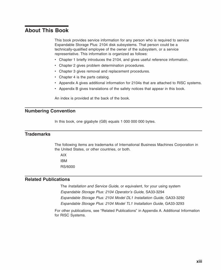
About This Book
This book provides service information for any person who is required to serviceExpandable Storage Plus: 2104 disk subsystems. That person could be atechnically-qualified employee of the owner of the subsystem, or a servicerepresentative. This information is organized as follows:
v Chapter 1 briefly introduces the 2104, and gives useful reference information.
v Chapter 2 gives problem determination procedures.
v Chapter 3 gives removal and replacement procedures.
v Chapter 4 is the parts catalog.
v Appendix A gives additional information for 2104s that are attached to RISC systems.
v Appendix B gives translations of the safety notices that appear in this book.
An index is provided at the back of the book.
Numbering Convention
In this book, one gigabyte (GB) equals 1 000 000 000 bytes.
Trademarks
The following items are trademarks of International Business Machines Corporation inthe United States, or other countries, or both.
AIX
IBM
RS/6000
Related PublicationsThe Installation and Service Guide, or equivalent, for your using system
Expandable Storage Plus: 2104 Operator’s Guide, SA33-3294
Expandable Storage Plus: 2104 Model DL1 Installation Guide, GA33-3292
Expandable Storage Plus: 2104 Model TL1 Installation Guide, GA33-3293
For other publications, see “Related Publications” in Appendix A. Additional Informationfor RISC Systems.
xiii
Electrostatic Discharge
When you handle field-replaceable units (FRUs) and other computer parts, take theseprecautions to avoid static damage:
v Limit your movement. Movement can cause static electricity to build up around you.
v Always touch computer parts carefully. Hold adapters and memory-modules by theiredges. Never touch any exposed circuits.
v Prevent other people from touching computer parts.
v Before you install a new part, touch the static-protective package that contains thepart against an unpainted metal part of the 2104 or using system for at least twoseconds. This action reduces static electricity in the package and in your body.
v Remove the part from its package and, if possible, install it directly into the 2104without putting the part down. If you need to put the part down, first place thestatic-protective package that contained the part onto a smooth, level surface, thenplace the part onto the package.
v Do not place the part onto any metal surface.
xiv 2104 Service Guide
Chapter 1. Reference Information
Note: Ensure that you read “Safety Notices” on page xi before you do any of theactions that are described in this book.
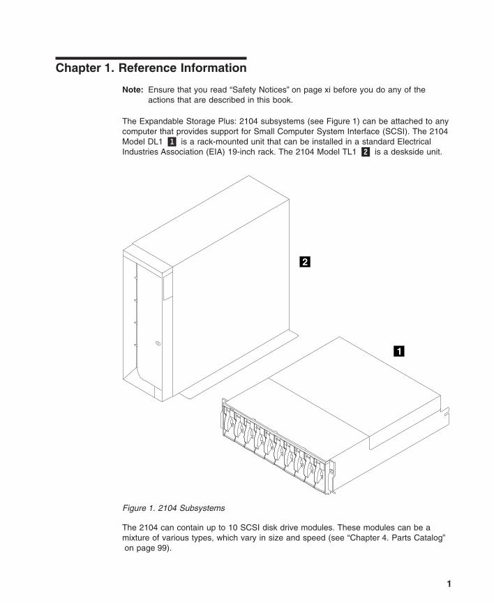
The Expandable Storage Plus: 2104 subsystems (see Figure 1) can be attached to anycomputer that provides support for Small Computer System Interface (SCSI). The 2104Model DL1 �1� is a rack-mounted unit that can be installed in a standard ElectricalIndustries Association (EIA) 19-inch rack. The 2104 Model TL1 �2� is a deskside unit.
The 2104 can contain up to 10 SCSI disk drive modules. These modules can be amixture of various types, which vary in size and speed (see “Chapter 4. Parts Catalog”on page 99).
1
2
Figure 1. 2104 Subsystems
1
The 2104 can be disconnected from its related SCSI attachments while the usingsystem is running. Also, most of the field-replaceable units (FRUs) of the 2104 can beremoved and replaced while the 2104 and the using system are running. For a list ofthose FRUs, see “Concurrent Maintenance” on page 53.
The 2104 has two fan-and-power-supply assemblies, or one fan-and-power-supplyassembly and one fan assembly, to provide all the necessary power and cooling. It alsohas up to two SCSI interface cards, which monitor and control the various functions ofthe 2104 (see also “SCSI Interface Cards” on page 3). Each SCSI interface card can beaccessed to collect enclosure information only if it is connected to an SCSI attachment.A switch card provides option selection switches (see also “Switch Card Switches” onpage 8).
The 2104 can be configured to the using system as a device if applicable. See“Configuring a 2104 to the Using System” in “Appendix A. Additional Information forRISC Systems”. When a 2104 is configured as a device:
v Errors that are detected in the 2104 can be collected by the diagnostics.
v Vital product data (VPD) for the 2104 can be accessed.
Most FRUs contain their own VPD. A using system can access this VPD while the 2104is being configured to that particular using system.
Enclosure configuration information is stored in several locations in the 2104 to allowconcurrent replacement of FRUs. When a new FRU is installed, any specialconfiguration information that is required by that FRU is read from other locations in the2104. That information is then used to update the new FRU. To ensure that theconfiguration is not corrupted or changed, always exchange FRUs one at a time.
2 2104 Service Guide
SCSI Interface Cards
The SCSI interface card of the 2104:
v Provides SCSI Enclosure Services (SES). RS/6000™ systems use these services.
v Provides Conner/Intel SCSI Accessed Fault-Tolerant Enclosures (SAF-TE) services.NT systems use these services; RS/6000 systems do not.
v Reads the VPD for the backplanes and the power supplies.
v Controls the Subsystem Check light and the disk drive module Check lights.
v Monitors the ‘Emergency Power Off Warning (EPOW)’ signal from the power-supplyassembly or assemblies. If an ‘EPOW’ signal occurs, the SCSI interface card sendsa ‘SCSI Reset’ signal to all the disk drive modules.
v Provides support for the hot plugging of the disk drive modules.
v Monitors itself. The SCSI interface card detects a self-failure if:
– The microprocessor fails.
– A SES function fails.
– The enclosure temperature is outside the specified limits.
If the 2104 has two SCSI interface cards, each SCSI interface card can be accessed tocollect enclosure information only if it is connected to an SCSI attachment. If both cardsare operational, the SES-active card provides all the functions described here. Theother card only detects self-failure and drives the internal SCSI bus.
Error Logging
Errors that the 2104 detects are not automatically logged to the system error log.
To collect error data, run diagnostics. For more details, see “Collecting Errors” in“Appendix A. Additional Information for RISC Systems”.
Configurations
Each SCSI interface card can be attached to only one using system. A 2104 that hasone SCSI interface card can, therefore, be attached to only one using system. A 2104that has two SCSI interface cards can be attached to two using systems. No SCSIterminators are needed.
Chapter 1. Reference Information 3
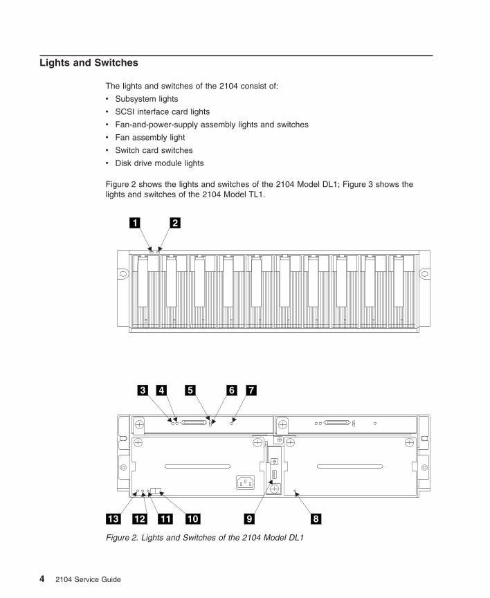
Lights and Switches
The lights and switches of the 2104 consist of:
v Subsystem lights
v SCSI interface card lights
v Fan-and-power-supply assembly lights and switches
v Fan assembly light
v Switch card switches
v Disk drive module lights
Figure 2 shows the lights and switches of the 2104 Model DL1; Figure 3 shows thelights and switches of the 2104 Model TL1.
1 2
3 4 5 6 7
8910111213
Figure 2. Lights and Switches of the 2104 Model DL1
4 2104 Service Guide
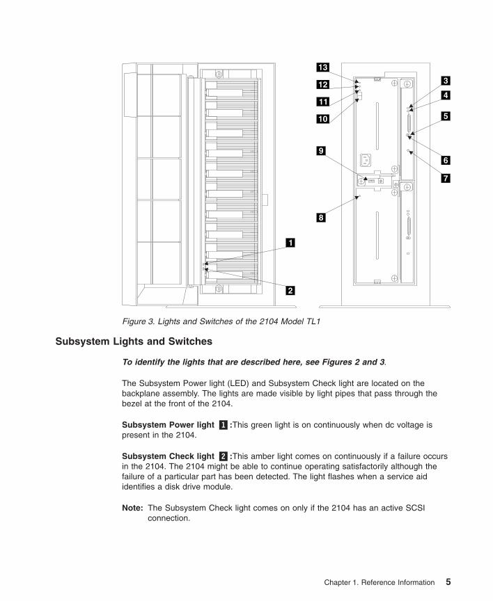
Subsystem Lights and Switches
To identify the lights that are described here, see Figures 2 and 3.
The Subsystem Power light (LED) and Subsystem Check light are located on thebackplane assembly. The lights are made visible by light pipes that pass through thebezel at the front of the 2104.
Subsystem Power light �1�:This green light is on continuously when dc voltage ispresent in the 2104.
Subsystem Check light �2�:This amber light comes on continuously if a failure occursin the 2104. The 2104 might be able to continue operating satisfactorily although thefailure of a particular part has been detected. The light flashes when a service aididentifies a disk drive module.
Note: The Subsystem Check light comes on only if the 2104 has an active SCSIconnection.
1
2
3
4
5
6
7
8
9
10
11
12
13
Figure 3. Lights and Switches of the 2104 Model TL1
Chapter 1. Reference Information 5
SCSI Interface Card Lights
To identify the lights that are described here, see Figures 2 and 3.
TERM POWER light �3�:This green light is on when the ‘TERMPWR’ signal is presenton the external SCSI connector, and the voltage is correct.
LVD/SE light �4�:This green light is on for differential SCSI operation, and off forsingle-ended SCSI operation.
ACTIVE light �5�:This amber light is on when a command is in progress.
RESET light �6�:This amber light comes on when a ‘power-on reset’ (POR) signal or a‘SCSI bus reset’ signal occurs.
FAULT light �7�:This amber light comes on if the SCSI interface card fails.
Fan-and-Power-Supply Assembly Lights and Switches
To identify the lights and switches that are described here, see Figures 2 and 3.
DC On/Standby switch �10�:This switch switches off the dc electrical power to the diskdrive modules and other components of the 2104. The switch must be set to On for thepower supply and the fan unit to start.
If the DC On/Standby switch is set to On (on either fan-and-power-supply assembly, iftwo are present), dc power in the 2104 is turned on automatically if all the followingconditions exist:
v Mainline power is present at the 2104.
v At least one fan-and-power-supply assembly is correctly installed.
v Either the Power Control switch on the Switch card is set to On or terminator poweris active in an external SCSI connection.
CHK light �11�:This amber light is on continuously if the fan-and-power-supplyassembly fails. When a power supply fails, the CHK light gets its power from the otherfan-and-power-supply assembly (if present). The light can, therefore, indicate a criticalpower supply failure only if the 2104 has two fan-and-power-supply assemblies.
Note: The CHK light is active only when the DC On/Standby switch is set to On.
DC PWR light �12�:This green light is on when the power supply assembly is supplyingdc power to the 2104.
AC PWR light �13�:This green light is on when mainline electrical power is present inthe power supply assembly.
6 2104 Service Guide
Fan Assembly Light
To identify the light that is described here, see Figures 2 and 3.
CHK light �8�:This amber light comes on if the fan fails.
Chapter 1. Reference Information 7
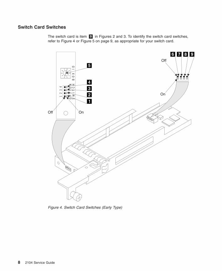
Switch Card Switches
The switch card is item �9� in Figures 2 and 3. To identify the switch card switches,refer to Figure 4 or Figure 5 on page 9, as appropriate for your switch card.
1
234
OnOff
0
1
23
45
6
7 8
9
BO
XI
D
12
34
OP
TI
ON
SW
IT
CH
5
On
Off
6 7 8 9
Figure 4. Switch Card Switches (Early Type)
8 2104 Service Guide
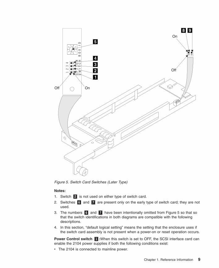
Notes:
1. Switch �2� is not used on either type of switch card.
2. Switches �6� and �7� are present only on the early type of switch card; they are notused.
3. The numbers �6� and �7� have been intentionally omitted from Figure 5 so that sothat the switch identifications in both diagrams are compatible with the followingdescriptions.
4. In this section, “default logical setting” means the setting that the enclosure uses ifthe switch card assembly is not present when a power-on or reset operation occurs.
Power Control switch �1�:When this switch is set to OFF, the SCSI interface card canenable the 2104 power supplies if both the following conditions exist:
v The 2104 is connected to mainline power.
1
234
OnOff
0
1
23
45
6
7 8
9
BO
XI
D
12
34
OP
TI
ON
SW
IT
CH
5On
Off
8 9
Figure 5. Switch Card Switches (Later Type)
Chapter 1. Reference Information 9
v The ‘terminator power (TERMPWR)’ signal is active in an external SCSI connection.
Under these conditions, the SCSI interface card provides a remote power on controlfunction. That is, the 2104 switches off automatically when all the connected usingsystems switch off; it switches on automatically when one using system switches on.
When the switch is set to ON, power is not controlled by the ‘TERMPWR’ signal. The2104 does not switch on and off automatically with the using system.
If the switch card assembly is not present when the 2104 is first switched on, or whenthe 2104 receives a ‘Reset’ signal, the default logical setting for this switch is ON.
Enable Enclosure Services switch �3�:When the switch is set to ON, the enclosureservices operate. When the switch is set to OFF, the 2104 does not respond torequests for enclosure services, and SCSI address 15 (the address of the SCSIenclosure services) is not used.
If the switch card assembly is not present when the 2104 is first switched on, or whenthe 2104 receives a ‘Reset’ signal, the default logical setting for this switch is ON.
Select Enclosure Services switch �4�:When the switch is set to ON, the SCSIenclosure services are selected. When the switch is set to OFF, the SAF-TE enclosureservices are selected.
Note: SAF-TE services are not supported on an RS/6000
If the switch card assembly is not present when the 2104 is first switched on, or whenthe 2104 receives a ‘Reset’ signal, the default logical setting for this switch is ON.
Enclosure ID switch �5�:This 10-position rotary switch sets the ID of the 2104. TheSES Inquiry command and the SAF-TE Buffer 1 command use the setting of thisswitch. If the switch card assembly is not present when the 2104 is first switched on, orwhen the 2104 receives a ‘Reset’ signal, the default logical setting for this switch isaddress 0.
The following switches can be accessed only when the switch card is removed from the2104. They are set during manufacture of the 2104, and indicate whether the 2104 is aModel DL1 or a Model TL1. In service operations, these switches need be checkedand, if necessary, set only when a replacement switch card is installed.
SCSI Address switch �8�:This switch, when set to ON, reverses the SCSI addressesof the disk drive modules. Normally, the switch is set to OFF.
Normally, on a 2104 Model DL1, the leftmost disk drive module slot has the lowestSCSI address; the rightmost slot has the highest SCSI address (see Table 1 onpage 22). When the switch is set to ON, the SCSI addresses are reversed. The leftmostdisk drive module slot now has the highest SCSI address; the rightmost slot has thelowest SCSI address.
10 2104 Service Guide
Note: On the 2104 Model DL1, the physical numbers of the disk drive module slotsare always 1 through 10, from left to right.
Normally, on a 2104 Model TL1, the topmost disk drive module slot has the highestSCSI address; the bottommost slot has the lowest SCSI address (see Table 1 onpage 22). When the switch is set to ON, the SCSI addresses are reversed. The topmostdisk drive module slot now has the lowest SCSI address; the bottommost slot has thehighest SCSI address.
Note: On the 2104 Model TL1, the physical numbers of the disk drive module slotsare always 1 through 10, from bottom to top.
If the switch card assembly is not present when the 2104 is first switched on, or whenthe 2104 receives a ‘Reset’ signal, the default logical setting for this switch is OFF.
2104 Orientation switch �9�:This switch must be set to OFF for the 2104 Model DL1,and to ON for the 2104 Model TL1:
v When the switch is set for the 2104 Model DL1, the two-color LEDs that are relatedto the 2104 Power light and to the 2104 Check light are set so that the left-hand LEDbecomes the green Power light, and the right-hand LED becomes the amber Checklight.
v When the switch is set for the 2104 Model TL1, the two-color LEDs that are relatedto the 2104 Power light and to the 2104 Check light are set so that the upper LEDbecomes the green Power light, and the lower LED becomes the amber Check light.
If the switch card assembly is not present when the 2104 is first switched on, or whenthe 2104 receives a ‘Reset’ signal, the default logical setting for this switch is OFF (thatis, for Model DL1).
Chapter 1. Reference Information 11
Disk Drive Module Lights
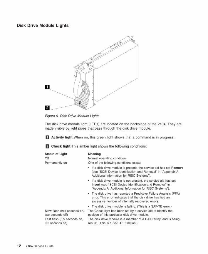
The disk drive module light (LEDs) are located on the backplane of the 2104. They aremade visible by light pipes that pass through the disk drive module.
�1� Activity light:When on, this green light shows that a command is in progress.
�2� Check light:This amber light shows the following conditions:
Status of Light MeaningOff Normal operating condition.Permanently on One of the following conditions exists:
v If a disk drive module is present, the service aid has set Remove(see “SCSI Device Identification and Removal” in “Appendix A.Additional Information for RISC Systems”).
v If a disk drive module is not present, the service aid has setInsert (see “SCSI Device Identification and Removal” in“Appendix A. Additional Information for RISC Systems”).
v The disk drive has reported a Predictive Failure Analysis (PFA)error. This error indicates that the disk drive has had anexcessive number of internally recovered errors.
v The disk drive module is failing. (This is a SAF-TE error.)Slow flash (two seconds on,two seconds off)
The Check light has been set by a service aid to identify theposition of this particular disk drive module.
Fast flash (0.5 seconds on,0.5 seconds off)
The disk drive module is a member of a RAID array, and is beingrebuilt. (This is a SAF-TE function.)
1
2
Figure 6. Disk Drive Module Lights
12 2104 Service Guide
Parts Locations
This section has two subsections; one is for the 2104 Model DL1, the other is for the2104 Model TL1. Go to the appropriate subsection.
Chapter 1. Reference Information 13
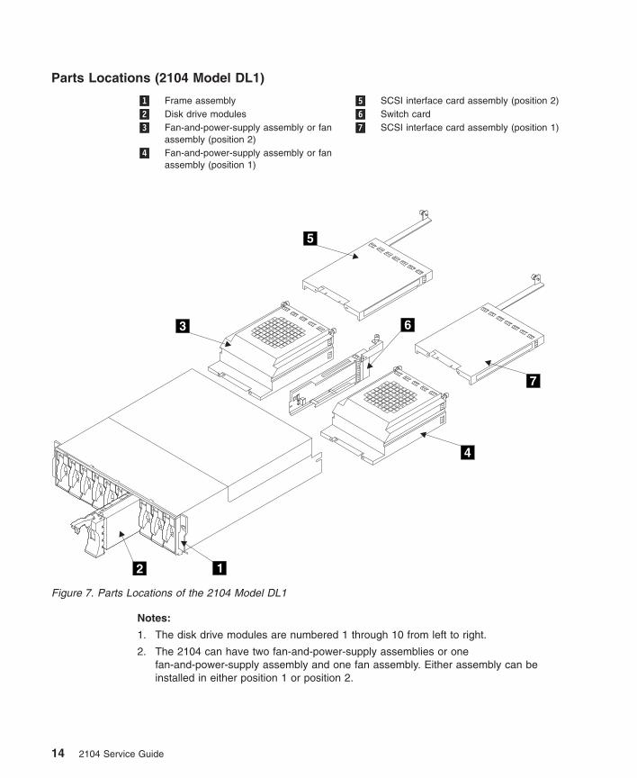
Parts Locations (2104 Model DL1)
�1� Frame assembly �5� SCSI interface card assembly (position 2)�2� Disk drive modules �6� Switch card�3� Fan-and-power-supply assembly or fan
assembly (position 2)�7� SCSI interface card assembly (position 1)
�4� Fan-and-power-supply assembly or fanassembly (position 1)
Notes:
1. The disk drive modules are numbered 1 through 10 from left to right.
2. The 2104 can have two fan-and-power-supply assemblies or onefan-and-power-supply assembly and one fan assembly. Either assembly can beinstalled in either position 1 or position 2.
12
3
4
5
6
7
Figure 7. Parts Locations of the 2104 Model DL1
14 2104 Service Guide
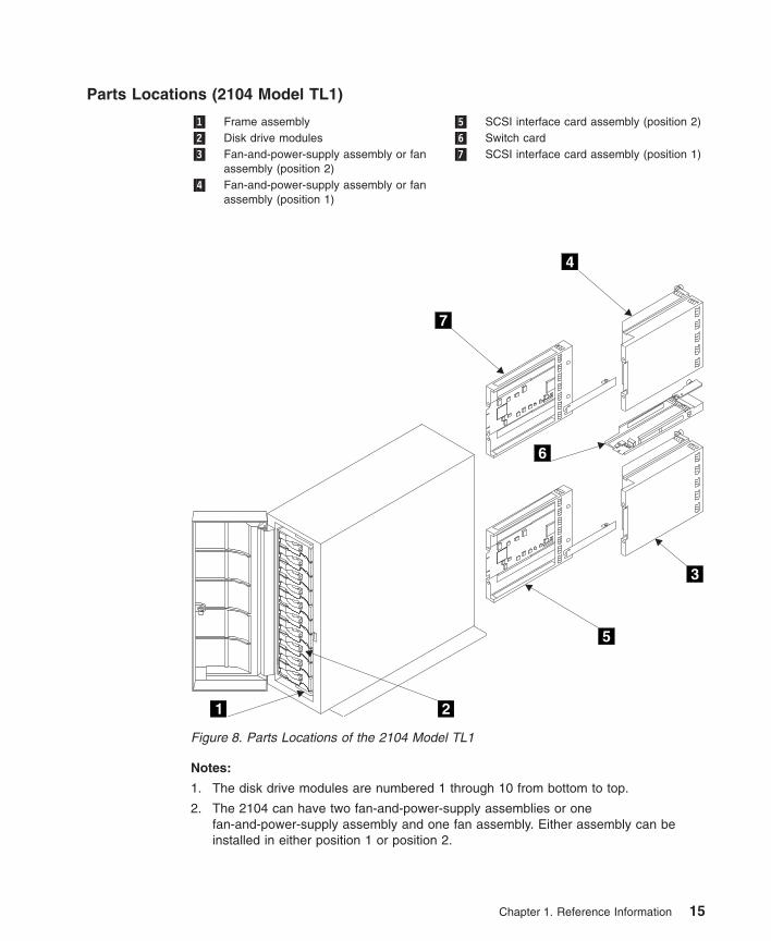
Parts Locations (2104 Model TL1)
�1� Frame assembly �5� SCSI interface card assembly (position 2)�2� Disk drive modules �6� Switch card�3� Fan-and-power-supply assembly or fan
assembly (position 2)�7� SCSI interface card assembly (position 1)
�4� Fan-and-power-supply assembly or fanassembly (position 1)
Notes:
1. The disk drive modules are numbered 1 through 10 from bottom to top.
2. The 2104 can have two fan-and-power-supply assemblies or onefan-and-power-supply assembly and one fan assembly. Either assembly can beinstalled in either position 1 or position 2.
1 2
5
6
4
3
7
Figure 8. Parts Locations of the 2104 Model TL1
Chapter 1. Reference Information 15
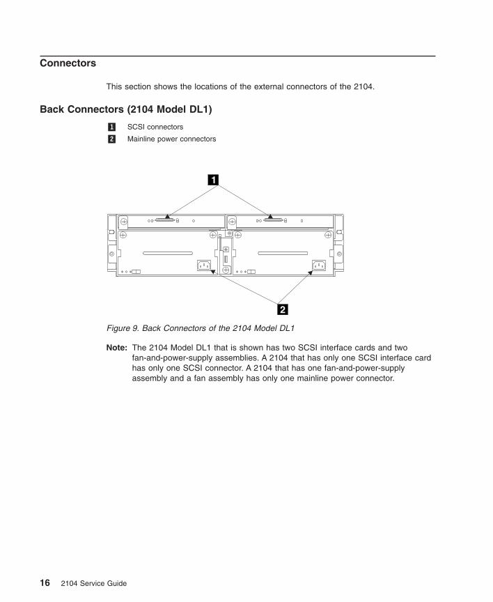
Connectors
This section shows the locations of the external connectors of the 2104.
Back Connectors (2104 Model DL1)
�1� SCSI connectors
�2� Mainline power connectors
Note: The 2104 Model DL1 that is shown has two SCSI interface cards and twofan-and-power-supply assemblies. A 2104 that has only one SCSI interface cardhas only one SCSI connector. A 2104 that has one fan-and-power-supplyassembly and a fan assembly has only one mainline power connector.
1
2
Figure 9. Back Connectors of the 2104 Model DL1
16 2104 Service Guide
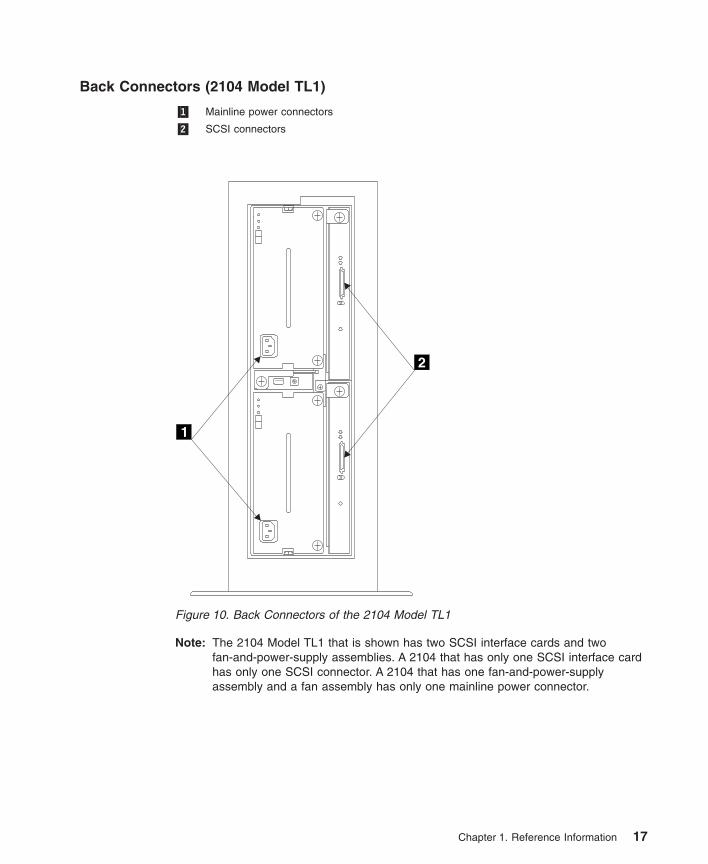
Back Connectors (2104 Model TL1)
�1� Mainline power connectors
�2� SCSI connectors
Note: The 2104 Model TL1 that is shown has two SCSI interface cards and twofan-and-power-supply assemblies. A 2104 that has only one SCSI interface cardhas only one SCSI connector. A 2104 that has one fan-and-power-supplyassembly and a fan assembly has only one mainline power connector.
1
2
Figure 10. Back Connectors of the 2104 Model TL1
Chapter 1. Reference Information 17
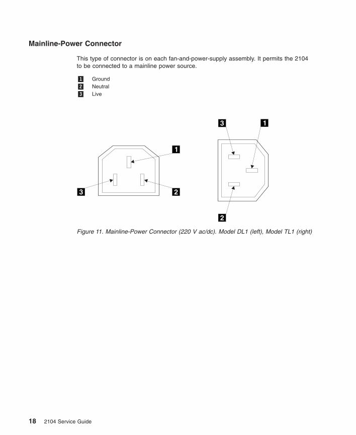
Mainline-Power Connector
This type of connector is on each fan-and-power-supply assembly. It permits the 2104to be connected to a mainline power source.
�1� Ground�2� Neutral�3� Live
1
1
2
2
3
3
Figure 11. Mainline-Power Connector (220 V ac/dc). Model DL1 (left), Model TL1 (right)
18 2104 Service Guide
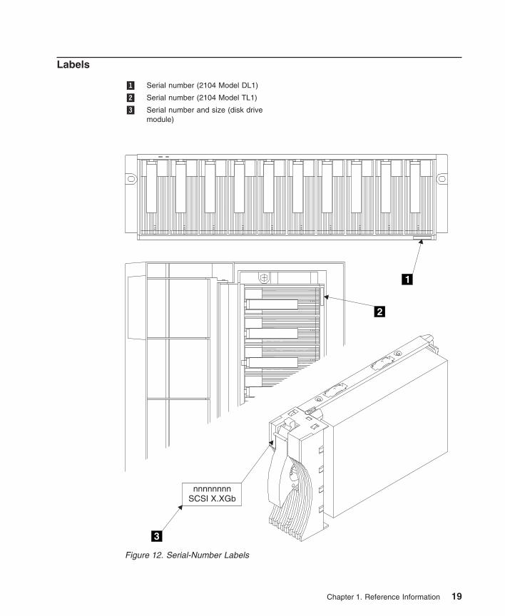
Labels
�1� Serial number (2104 Model DL1)
�2� Serial number (2104 Model TL1)
�3� Serial number and size (disk drivemodule)
1
2
nnnnnnnnSCSI X.XGb
3
Figure 12. Serial-Number Labels
Chapter 1. Reference Information 19
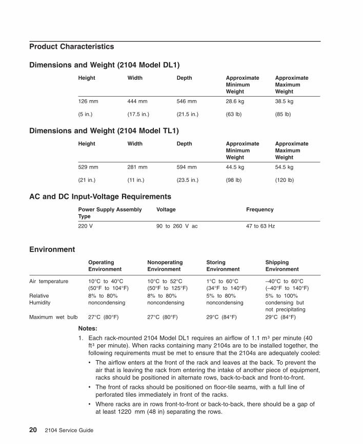
Product Characteristics
Dimensions and Weight (2104 Model DL1)
Height Width Depth ApproximateMinimumWeight
ApproximateMaximumWeight
126 mm
(5 in.)
444 mm
(17.5 in.)
546 mm
(21.5 in.)
28.6 kg
(63 lb)
38.5 kg
(85 lb)
Dimensions and Weight (2104 Model TL1)
Height Width Depth ApproximateMinimumWeight
ApproximateMaximumWeight
529 mm
(21 in.)
281 mm
(11 in.)
594 mm
(23.5 in.)
44.5 kg
(98 lb)
54.5 kg
(120 lb)
AC and DC Input-Voltage Requirements
Power Supply AssemblyType
Voltage Frequency
220 V 90 to 260 V ac 47 to 63 Hz
Environment
OperatingEnvironment
NonoperatingEnvironment
StoringEnvironment
ShippingEnvironment
Air temperature 10°C to 40°C(50°F to 104°F)
10°C to 52°C(50°F to 125°F)
1°C to 60°C(34°F to 140°F)
–40°C to 60°C(–40°F to 140°F)
RelativeHumidity
8% to 80%noncondensing
8% to 80%noncondensing
5% to 80%noncondensing
5% to 100%condensing butnot precipitating
Maximum wet bulb 27°C (80°F) 27°C (80°F) 29°C (84°F) 29°C (84°F)
Notes:
1. Each rack-mounted 2104 Model DL1 requires an airflow of 1.1 m³ per minute (40ft³ per minute). When racks containing many 2104s are to be installed together, thefollowing requirements must be met to ensure that the 2104s are adequately cooled:
v The airflow enters at the front of the rack and leaves at the back. To prevent theair that is leaving the rack from entering the intake of another piece of equipment,racks should be positioned in alternate rows, back-to-back and front-to-front.
v The front of racks should be positioned on floor-tile seams, with a full line ofperforated tiles immediately in front of the racks.
v Where racks are in rows front-to-front or back-to-back, there should be a gap ofat least 1220 mm (48 in) separating the rows.
20 2104 Service Guide
v To ensure correct air flow within each rack, the rack filler plates must be installedin unused positions. Also, all the gaps in the front of the racks must be sealed,including the gaps between the 2104s.
2. The recommended operating temperature is 22°C (72°F) or lower.
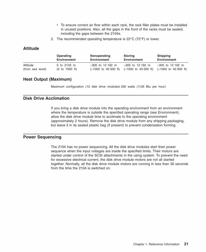
Altitude
OperatingEnvironment
NonoperatingEnvironment
StoringEnvironment
ShippingEnvironment
Altitude(from sea level)
0 to 2133 m(0 to 7000 ft)
–305 to 12 192 m(–1000 to 40 000 ft)
–305 to 12 192 m(–1000 to 40 000 ft)
–305 to 12 192 m(–1000 to 40 000 ft)
Heat Output (Maximum)
Maximum configuration (10 disk drive modules) 330 watts (1126 Btu per hour)
Disk Drive Acclimation
If you bring a disk drive module into the operating environment from an environmentwhere the temperature is outside the specified operating range (see Environment),allow the disk drive module time to acclimate to the operating environment(approximately 2 hours). Remove the disk drive module from any shipping packaging,but leave it in its sealed plastic bag (if present) to prevent condensation forming.
Power Sequencing
The 2104 has no power sequencing. All the disk drive modules start their powersequence when the input voltages are inside the specified limits. Their motors arestarted under control of the SCSI attachments in the using system. To prevent the needfor excessive electrical current, the disk drive module motors are not all startedtogether. Normally, all the disk drive module motors are running in less than 30 secondsfrom the time the 2104 is switched on.
Chapter 1. Reference Information 21
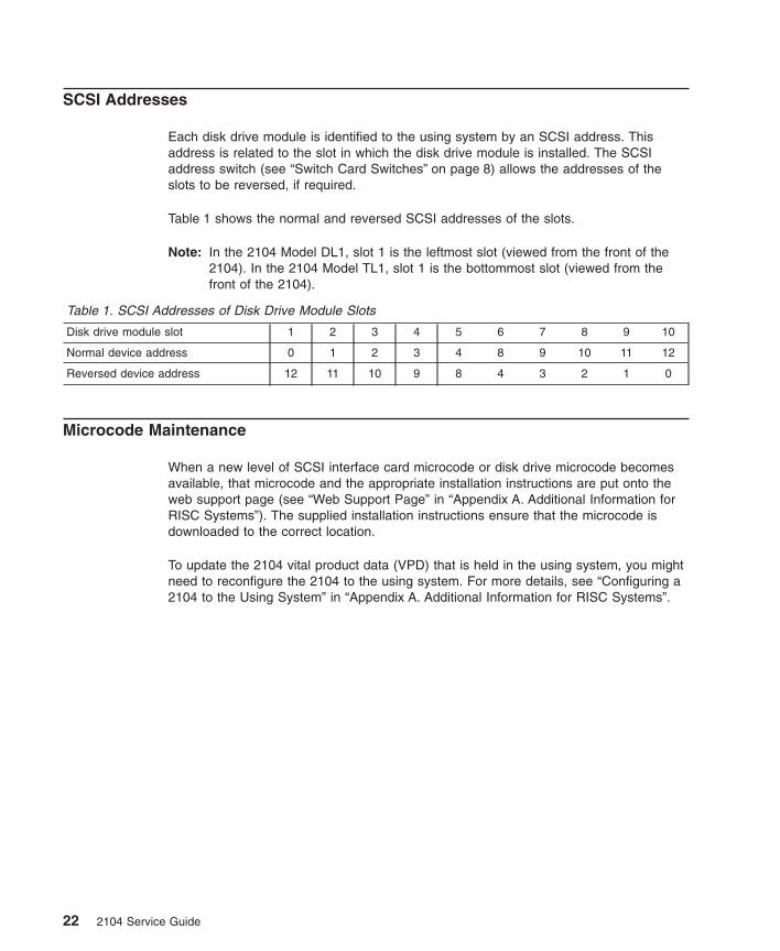
SCSI Addresses
Each disk drive module is identified to the using system by an SCSI address. Thisaddress is related to the slot in which the disk drive module is installed. The SCSIaddress switch (see “Switch Card Switches” on page 8) allows the addresses of theslots to be reversed, if required.
Table 1 shows the normal and reversed SCSI addresses of the slots.
Note: In the 2104 Model DL1, slot 1 is the leftmost slot (viewed from the front of the2104). In the 2104 Model TL1, slot 1 is the bottommost slot (viewed from thefront of the 2104).
Table 1. SCSI Addresses of Disk Drive Module Slots
Disk drive module slot 1 2 3 4 5 6 7 8 9 10
Normal device address 0 1 2 3 4 8 9 10 11 12
Reversed device address 12 11 10 9 8 4 3 2 1 0
Microcode Maintenance
When a new level of SCSI interface card microcode or disk drive microcode becomesavailable, that microcode and the appropriate installation instructions are put onto theweb support page (see “Web Support Page” in “Appendix A. Additional Information forRISC Systems”). The supplied installation instructions ensure that the microcode isdownloaded to the correct location.
To update the 2104 vital product data (VPD) that is held in the using system, you mightneed to reconfigure the 2104 to the using system. For more details, see “Configuring a2104 to the Using System” in “Appendix A. Additional Information for RISC Systems”.
22 2104 Service Guide
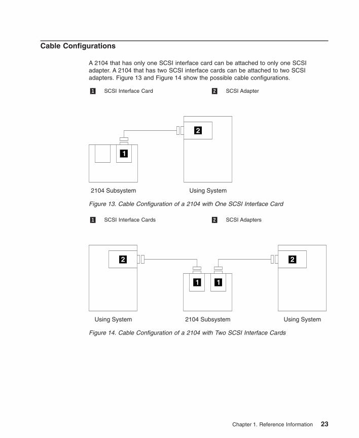
Cable Configurations
A 2104 that has only one SCSI interface card can be attached to only one SCSIadapter. A 2104 that has two SCSI interface cards can be attached to two SCSIadapters. Figure 13 and Figure 14 show the possible cable configurations.
�1� SCSI Interface Card �2� SCSI Adapter
�1� SCSI Interface Cards �2� SCSI Adapters
Figure 13. Cable Configuration of a 2104 with One SCSI Interface Card
Figure 14. Cable Configuration of a 2104 with Two SCSI Interface Cards
Chapter 1. Reference Information 23
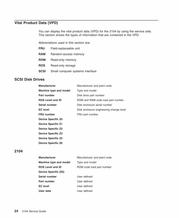
Vital Product Data (VPD)
You can display the vital product data (VPD) for the 2104 by using the service aids.This section shows the types of information that are contained in the VPD.
Abbreviations used in this section are:
FRU Field-replaceable unit
RAM Random-access memory
ROM Read-only memory
ROS Read-only storage
SCSI Small computer systems interface
SCSI Disk Drives
Manufacturer Manufacturer and plant code
Machine type and model Type and model
Part number Disk drive part number
ROS Level and ID ROM and RAM code load part number
Serial number Disk enclosure serial number
EC level Disk enclosure engineering change level
FRU number FRU part number
Device Specific Z0
Device Specific Z1
Device Specific Z2
Device Specific Z3
Device Specific Z5
Device Specific Z6
2104
Manufacturer Manufacturer and plant code
Machine type and model Type and model
ROS Level and ID ROM code load part number
Device Specific (Z0)
Serial number User defined
Part number User defined
EC level User defined
User data User defined
24 2104 Service Guide
2104 Service Aids
Service aids are available for the 2104. For descriptions of those service aids, see“System Service Aids” in “Appendix A. Additional Information for RISC Systems”.
2104 Enclosure Services
If the using system and the 2104 are both operating, you can use the enclosureservices to determine the status of the 2104. The 2104 enclosure services can operatein either of two modes, which you can select with the Enable Enclosure Services switch(see “Switch Card Switches” on page 8):
v ANSI SCSI Enclosure Service (SES)
v SAF-TE
ANSI SCSI Enclosure Services (SES) Mode
Use the Receive Diagnostic Results command, and go to the enclosure status page(page 02). That page shows the health status of the 2104, and the status of thecomponents of the 2104.
In the health status byte, the critical fault bit, if set, indicates that a component in the2104 has failed.
In the fan element, power supply element, and enclosure services element status fields,the fault bit, if set, indicates the failure of a particular component.
SAF-TE Mode
Note: SAF-TE mode is not supported on RS/6000.
Use the Read Buffer command, and go to the enclosure status page (page 02). In thefan element and power supply element status fields, the fault bit, if set, indicates thefailure of the component.
Chapter 1. Reference Information 25
Service Inspection Guide
This inspection guide helps you to identify possible unsafe conditions on 2104s. Each2104 has the necessary safety items installed to protect users and service personnelfrom injury. This guide addresses only those items. You should use your goodjudgment, however, to identify possible safety hazards that are not covered by thisguide.
If any unsafe conditions are present, you must determine how serious the possiblehazard could be, and whether you should continue without first correcting the problem.
Consider the following conditions and the safety hazards they present:
v Electrical hazards (especially primary power): Primary voltage on the frame cancause serious or lethal electrical shock.
v Mechanical hazards: Loose or missing items (for example, nuts and screws) cancause serious injury.
Using the following inspection checklist as a guide, inspect the 2104 for unsafeconditions. See, if necessary, any suitable safety publications.
Inspection Checklist1. Remove all power from the 2104 (see “All Power” on page 57).
2. Check the frame for damage (loose, broken, or sharp edges).
3. Check the power cables and ensure that:
a. The third-wire ground connector is in good condition. Use a meter to check thatthe third-wire ground continuity is 0.1 ohm or less between the external groundpin and the frame ground.
b. The insulation is not worn or damaged.
4. Check for any obvious nonstandard changes. Use good judgment about the safetyof any such changes.
5. Check inside the 2104 for any obvious unsafe conditions, such as metal particles,water or other fluids, or marks of overheating, fire, or smoke damage.
6. Check for worn, damaged, or pinched cables.
7. Ensure that the voltage specified on the product-information label matches thespecified voltage of the electrical power outlet. If necessary, verify the voltage.
8. Inspect the fan-and-power-supply assemblies, and check that the fasteners in thecover of the power-supply unit (screws or rivets) have not been removed ordisturbed.
9. Before connecting the 2104 to the using system, check the grounding as describedin “Checking the Grounding of the 2104” on page 27.
26 2104 Service Guide
Checking the Grounding of the 2104
Go to the appropriate subsection for the 2104 that you are servicing.
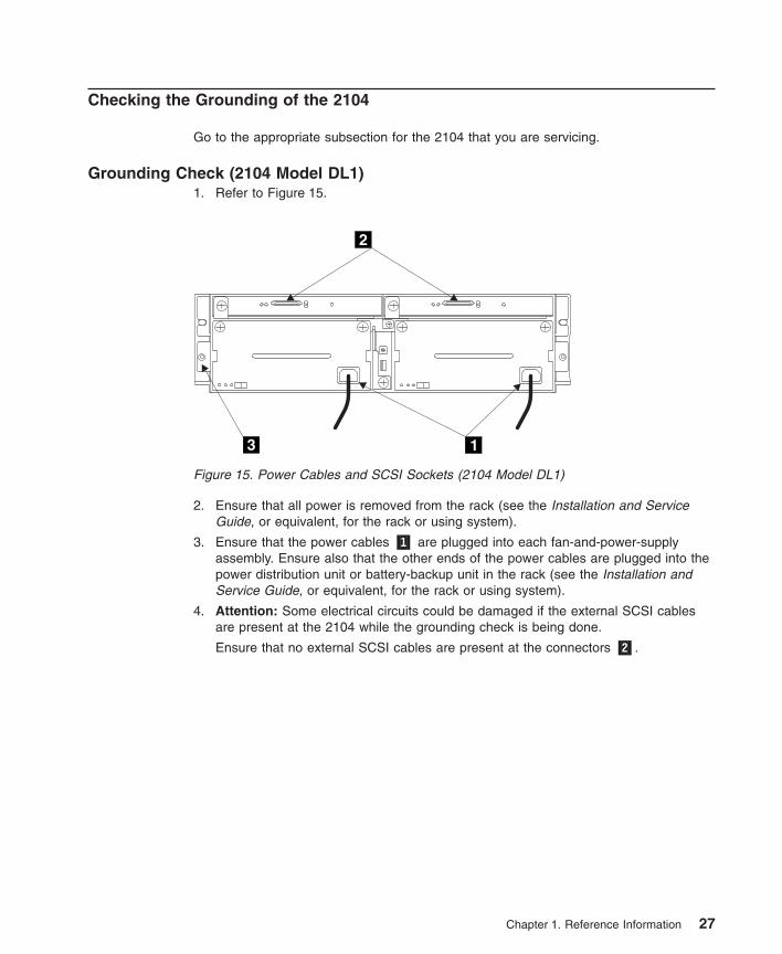
Grounding Check (2104 Model DL1)1. Refer to Figure 15.
2. Ensure that all power is removed from the rack (see the Installation and ServiceGuide, or equivalent, for the rack or using system).
3. Ensure that the power cables �1� are plugged into each fan-and-power-supplyassembly. Ensure also that the other ends of the power cables are plugged into thepower distribution unit or battery-backup unit in the rack (see the Installation andService Guide, or equivalent, for the rack or using system).
4. Attention: Some electrical circuits could be damaged if the external SCSI cablesare present at the 2104 while the grounding check is being done.
Ensure that no external SCSI cables are present at the connectors �2�.
2
13
Figure 15. Power Cables and SCSI Sockets (2104 Model DL1)
Chapter 1. Reference Information 27
5. Follow your local procedures and check the grounding of the 2104. Any testequipment must be connected to the frame of the 2104 �3�.
If the grounding is correct (see step 3a on page 26), go no further with theseinstructions.
If the grounding is not correct, unplug the power cables from thefan-and-power-supply assemblies in the 2104, and continue with step 6.
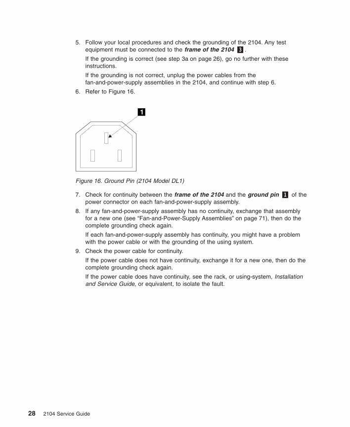
6. Refer to Figure 16.
7. Check for continuity between the frame of the 2104 and the ground pin �1� of thepower connector on each fan-and-power-supply assembly.
8. If any fan-and-power-supply assembly has no continuity, exchange that assemblyfor a new one (see “Fan-and-Power-Supply Assemblies” on page 71), then do thecomplete grounding check again.
If each fan-and-power-supply assembly has continuity, you might have a problemwith the power cable or with the grounding of the using system.
9. Check the power cable for continuity.
If the power cable does not have continuity, exchange it for a new one, then do thecomplete grounding check again.
If the power cable does have continuity, see the rack, or using-system, Installationand Service Guide, or equivalent, to isolate the fault.
1
Figure 16. Ground Pin (2104 Model DL1)
28 2104 Service Guide
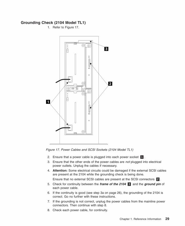
Grounding Check (2104 Model TL1)1. Refer to Figure 17.
2. Ensure that a power cable is plugged into each power socket �1�.
3. Ensure that the other ends of the power cables are not plugged into electricalpower outlets. Unplug the cables if necessary.
4. Attention: Some electrical circuits could be damaged if the external SCSI cablesare present at the 2104 while the grounding check is being done.
Ensure that no external SCSI cables are present at the SCSI connectors �2�.
5. Check for continuity between the frame of the 2104 �3� and the ground pin ofeach power cable.
6. If the continuity is good (see step 3a on page 26), the grounding of the 2104 iscorrect. Go no further with these instructions.
7. If the grounding is not correct, unplug the power cables from the mainline powerconnectors. Then continue with step 8.
8. Check each power cable, for continuity.
1
2
3
Figure 17. Power Cables and SCSI Sockets (2104 Model TL1)
Chapter 1. Reference Information 29
9. If either power cable is failing, exchange it for a new one, then go to step 10 .
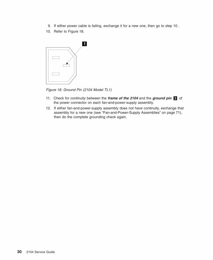
10. Refer to Figure 18.
11. Check for continuity between the frame of the 2104 and the ground pin �1� ofthe power connector on each fan-and-power-supply assembly.
12. If either fan-and-power-supply assembly does not have continuity, exchange thatassembly for a new one (see “Fan-and-Power-Supply Assemblies” on page 71),then do the complete grounding check again.
1
Figure 18. Ground Pin (2104 Model TL1)
30 2104 Service Guide
Chapter 2. Problem Determination Procedures
Problem determination procedures are provided by power-on self-tests (POSTs), servicerequest numbers, and maintenance analysis procedures (MAPs). Some of theseprocedures use the service aids that are described in the user or maintenanceinformation for your using-system SCSI attachment.
Disk Drive Module Power-On Self-Tests (POSTs)
The disk drive module POSTs start each time the module is switched on, or when aSend Diagnostic command is received. They check whether the disk drive module isworking correctly. The POSTs also help verify a repair after a FRU has beenexchanged.
The tests are POST-1 and POST-2.
POST-1 runs immediately after the ‘power-on reset’ line goes inactive, and before thedisk drive module motor starts. POST-1 includes tests of:
v Microprocessor
v ROM
v Safety circuits.
If POST-1 completes successfully, POST-2 is enabled.
If POST-1 fails, the disk drive module is not configured into the system.
POST-2 runs after the disk drive module motor has started. POST-2 includes tests of:
v Motor control
v Servo control
v Read and write on the diagnostic cylinder (repeated for all heads)
v Error checking and correction (ECC).
If POST-2 completes successfully, the disk drive module is ready for use with thesystem.
If POST-2 fails, the disk drive module is not configured into the system.
SCSI Interface Card Power-On Self-Tests (POSTs)
The SCSI interface card POSTs start each time power is switched on, or when a Resetcommand is sent from the using-system SCSI attachment. They check only the internalcomponents of the SCSI interface card; they do not check any interfaces to otherFRUs.
31
If the POSTs complete successfully, control passes to the functional microcode of theSCSI interface card. This microcode checks all the internal interfaces of the 2104, andreports failures to the using system.
If the POSTs fail:
v The SCSI interface card Check light and the 2104 Check light come on.
v The functional operation of the 2104 is not affected. For example, the customer stillhas access to all the disk drive modules.
v If a second SCSI interface card is present, it becomes the SES active card.
v The failure is reported:
– If the failure occurs at system bringup time, the using system detects that the2104 is missing, and reports an error.
– If the failure occurs at any time other than system bringup time, the hourly healthcheck reports the failure.
Service Request Numbers (SRNs)
Service request numbers (SRNs) are generated for the 2104 by diagnostics and theSES healthcheck (see “Error Logging” on page 3). SRNs help you to identify the causeof a problem, the failing field-replaceable units (FRUs), and the service actions thatmight be needed to solve the problem.
The SRN Table
The table in this section lists the SRNs and describes the actions you should do. Thetable columns are:
SRN The service reference number.FRU list The FRU or FRUs that might be causing the problem (see also “FRU Names
Used in the SRN Table” on page 33), and how likely it is (by percentage) thatthe FRU is causing the problem.
Problem A description of the problem and the action you must take.
Abbreviations used in the table are:
FRU Field-replaceable unit
Using the SRN Table
Important: You should have been sent here from MAP 2010: 2104 – START. Do notstart problem determination from the SRN table; always go to “MAP 2010:2104 – START” on page 38 first.
1. Locate the SRN in the table. If you cannot find a particular SRN in the table, goto the SRN list that is in the user or maintenance information for your using-systemSCSI attachment. If you still cannot find the SRN, you have a problem with thediagnostics, the microcode, or the documentation. Call your support center forassistance.
32 2104 Service Guide
2. Read carefully the “Action” you must do for the problem. Do not exchange FRUsunless you are instructed to do so.
3. Unless instructed otherwise, exchange only one FRU at a time, starting from thetop of the FRU list for that SRN. Always use instructions given in “Chapter 3.Removal and Replacement Procedures” when exchanging FRUs; a page referenceis given with each FRU in the FRU list. After each FRU is exchanged, go to “MAP2410: 2104 – Repair Verification” on page 52 to verify the repair.
FRU Names Used in the SRN Table
This section provides a glossary of the FRU names used.
FRU Name in Table Definition
Frame assembly The frame of the 2104 and the backplanes and cables that it contains.Disk drive module A disk drive attached to a carrier that plugs into one of the backplanes of
the 2104.External SCSI cable A cable that connects the 2104 to an SCSI attachment or to another
device (for example, another 2104).Fan-and-power-supply assembly
An assembly that consists of a power supply unit and a fan. The 2104 canhave two fan-and-power-supply assemblies, or one fan-and-power-supplyassembly and one fan assembly, whichever is suitable for the requiredconfiguration.
Fan assembly An assembly that contains a dc cooling fan. The 2104 can have twofan-and-power-supply assemblies, or one fan-and-power-supply assemblyand one fan assembly, whichever is suitable for the required configuration.
SCSI interface cardassembly
The card that monitors and controls the various functions of the 2104.
SCSI attachment The means by which the 2104 is connected to the using system (forexample, an SCSI adapter card). The SCSI attachment is located in theusing system.
Switch cardassembly
The assembly that contains all the option switches for the 2104.
Chapter 2. Problem Determination Procedures 33
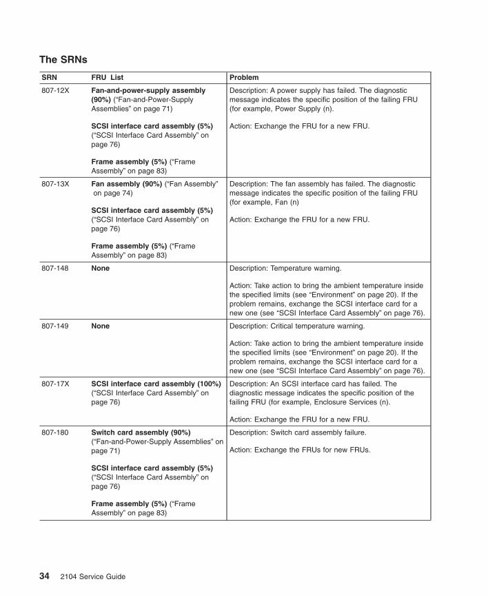
The SRNs
SRN FRU List Problem
807-12X Fan-and-power-supply assembly(90%) (“Fan-and-Power-SupplyAssemblies” on page 71)
SCSI interface card assembly (5%)(“SCSI Interface Card Assembly” onpage 76)
Frame assembly (5%) (“FrameAssembly” on page 83)
Description: A power supply has failed. The diagnosticmessage indicates the specific position of the failing FRU(for example, Power Supply (n).
Action: Exchange the FRU for a new FRU.
807-13X Fan assembly (90%) (“Fan Assembly”on page 74)
SCSI interface card assembly (5%)(“SCSI Interface Card Assembly” onpage 76)
Frame assembly (5%) (“FrameAssembly” on page 83)
Description: The fan assembly has failed. The diagnosticmessage indicates the specific position of the failing FRU(for example, Fan (n)
Action: Exchange the FRU for a new FRU.
807-148 None Description: Temperature warning.
Action: Take action to bring the ambient temperature insidethe specified limits (see “Environment” on page 20). If theproblem remains, exchange the SCSI interface card for anew one (see “SCSI Interface Card Assembly” on page 76).
807-149 None Description: Critical temperature warning.
Action: Take action to bring the ambient temperature insidethe specified limits (see “Environment” on page 20). If theproblem remains, exchange the SCSI interface card for anew one (see “SCSI Interface Card Assembly” on page 76).
807-17X SCSI interface card assembly (100%)(“SCSI Interface Card Assembly” onpage 76)
Description: An SCSI interface card has failed. Thediagnostic message indicates the specific position of thefailing FRU (for example, Enclosure Services (n).
Action: Exchange the FRU for a new FRU.
807-180 Switch card assembly (90%)(“Fan-and-Power-Supply Assemblies” onpage 71)
SCSI interface card assembly (5%)(“SCSI Interface Card Assembly” onpage 76)
Frame assembly (5%) (“FrameAssembly” on page 83)
Description: Switch card assembly failure.
Action: Exchange the FRUs for new FRUs.
34 2104 Service Guide
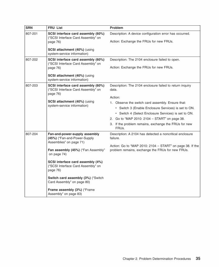
SRN FRU List Problem
807-201 SCSI interface card assembly (60%)(“SCSI Interface Card Assembly” onpage 76)
SCSI attachment (40%) (usingsystem-service information)
Description: A device configuration error has occurred.
Action: Exchange the FRUs for new FRUs.
807-202 SCSI interface card assembly (60%)(“SCSI Interface Card Assembly” onpage 76)
SCSI attachment (40%) (usingsystem-service information)
Description: The 2104 enclosure failed to open.
Action: Exchange the FRUs for new FRUs.
807-203 SCSI interface card assembly (60%)(“SCSI Interface Card Assembly” onpage 76)
SCSI attachment (40%) (usingsystem-service information)
Description: The 2104 enclosure failed to return inquirydata.
Action:
1. Observe the switch card assembly. Ensure that:
v Switch 3 (Enable Enclosure Services) is set to ON.
v Switch 4 (Select Enclosure Services) is set to ON.
2. Go to “MAP 2010: 2104 – START” on page 38.
3. If the problem remains, exchange the FRUs for newFRUs.
807-204 Fan-and-power-supply assembly(45%) (“Fan-and-Power-SupplyAssemblies” on page 71)
Fan assembly (45%) (“Fan Assembly”on page 74)
SCSI interface card assembly (4%)(“SCSI Interface Card Assembly” onpage 76)
Switch card assembly (3%) (“SwitchCard Assembly” on page 80)
Frame assembly (3%) (“FrameAssembly” on page 83)
Description: A 2104 has detected a noncritical enclosurefailure.
Action: Go to “MAP 2010: 2104 – START” on page 38. If theproblem remains, exchange the FRUs for new FRUs.
Chapter 2. Problem Determination Procedures 35
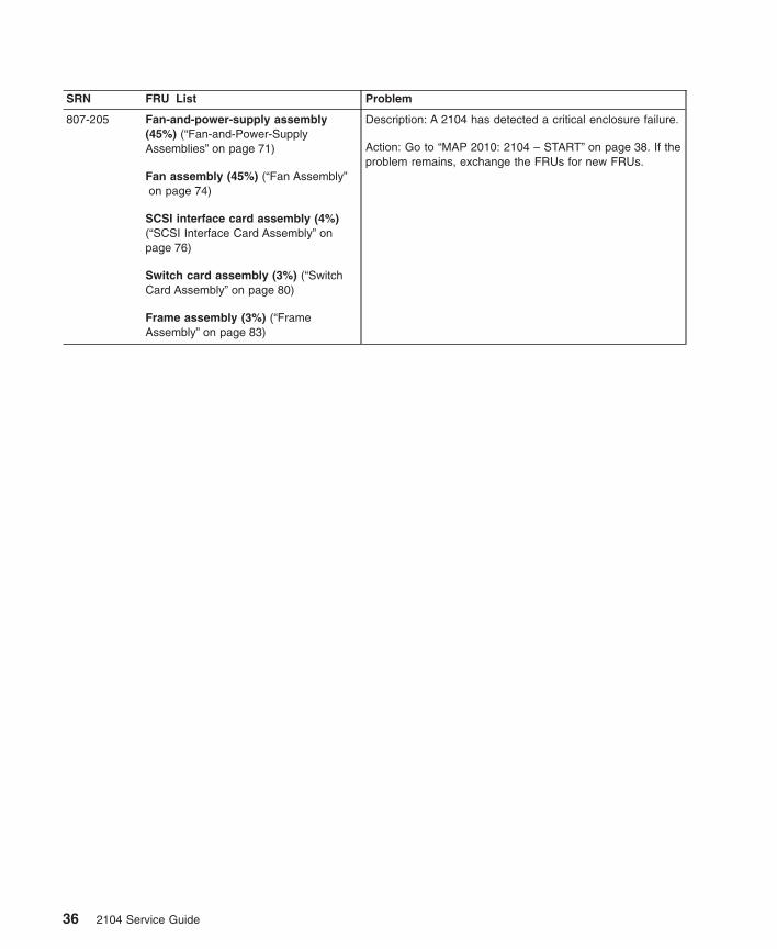
SRN FRU List Problem
807-205 Fan-and-power-supply assembly(45%) (“Fan-and-Power-SupplyAssemblies” on page 71)
Fan assembly (45%) (“Fan Assembly”on page 74)
SCSI interface card assembly (4%)(“SCSI Interface Card Assembly” onpage 76)
Switch card assembly (3%) (“SwitchCard Assembly” on page 80)
Frame assembly (3%) (“FrameAssembly” on page 83)
Description: A 2104 has detected a critical enclosure failure.
Action: Go to “MAP 2010: 2104 – START” on page 38. If theproblem remains, exchange the FRUs for new FRUs.
36 2104 Service Guide
Maintenance Analysis Procedures (MAPs)
These maintenance analysis procedures (MAPs) describe how to analyze a continuousfailure that has occurred in a 2104 containing one or more SCSI disk drive modules.Failing field-replaceable units (FRUs) of the 2104 can be isolated with these MAPs.
How to Use these MAPs
Attention: Unless the using system needs to be switched off for some other reason, donot switch off the using system when servicing the 2104 or any of its SCSI devices.Power cables and external SCSI cables that connect the 2104 to the using system canbe disconnected while that system is running.
v To isolate the FRUs in the failing 2104, do the actions and answer the questionsgiven in these MAPs.
v When instructed to exchange two or more FRUs in sequence:
1. Exchange the first FRU in the list for a new one.
2. Verify that the problem is solved. For some problems, verification means runningthe diagnostic programs (see the using-system service procedures).
3. If the problem remains:
a. Reinstall the original FRU.
b. Exchange the next FRU in the list for a new one.
4. Repeat steps 2 and 3 until either the problem is solved, or all the related FRUshave been exchanged.
5. Do the next action indicated by the MAP.
v See “Lights and Switches” on page 4 for locations and descriptions of the lights andswitches.
Attention: Disk drive modules are fragile. Handle them with care, and keep them wellaway from strong magnetic fields.
Chapter 2. Problem Determination Procedures 37
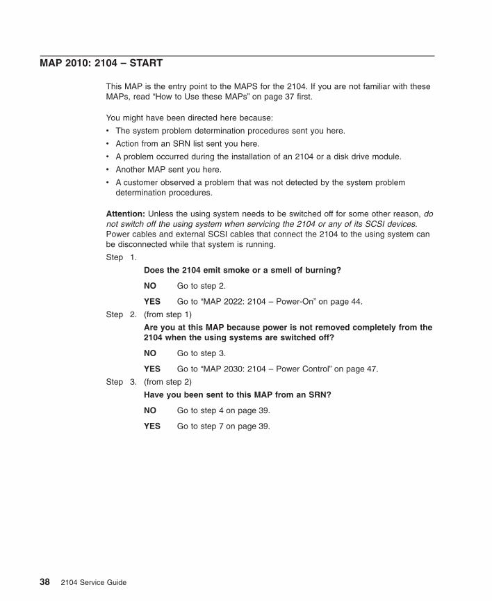
MAP 2010: 2104 – START
This MAP is the entry point to the MAPS for the 2104. If you are not familiar with theseMAPs, read “How to Use these MAPs” on page 37 first.
You might have been directed here because:
v The system problem determination procedures sent you here.
v Action from an SRN list sent you here.
v A problem occurred during the installation of an 2104 or a disk drive module.
v Another MAP sent you here.
v A customer observed a problem that was not detected by the system problemdetermination procedures.
Attention: Unless the using system needs to be switched off for some other reason, donot switch off the using system when servicing the 2104 or any of its SCSI devices.Power cables and external SCSI cables that connect the 2104 to the using system canbe disconnected while that system is running.
Step 1.
Does the 2104 emit smoke or a smell of burning?
NO Go to step 2.
YES Go to “MAP 2022: 2104 – Power-On” on page 44.
Step 2. (from step 1)
Are you at this MAP because power is not removed completely from the2104 when the using systems are switched off?
NO Go to step 3.
YES Go to “MAP 2030: 2104 – Power Control” on page 47.
Step 3. (from step 2)
Have you been sent to this MAP from an SRN?
NO Go to step 4 on page 39.
YES Go to step 7 on page 39.
38 2104 Service Guide
Step 4. (from step 3)
Have the system diagnostics or problem determination proceduresgiven you an SRN for the 2104 (sesn)?
NO
v If the system diagnostics are available, go to step 5.
v If the system diagnostics are not available, but the stand-alonediagnostics are available:
a. Run the stand-alone diagnostics.
b. Go to step 6.
v If neither the system diagnostics nor the stand-alone diagnosticsare available, go to step 7.
YES Go to “Service Request Numbers (SRNs)” on page 32.
Step 5. (from step 4)
a. Run the concurrent diagnostics. For information about how to runconcurrent diagnostics, see “Concurrent Diagnostics” in “Appendix A.Additional Information for RISC Systems”.
b. When the concurrent diagnostics have completed, go to step 6.
Step 6. (from steps 4 and 5)
Did the diagnostics give you an SRN for the 2104?
NO Go to step 7.
YES Go to “Service Request Numbers (SRNs)” on page 32.
Step 7. (from steps 3, 4, and 6)
Is the Subsystem Check light flashing?
NO Go to step 8.
YES A device is in Identify mode.
Step 8. (from step 7)
Is the Subsystem Check light on continuously?
NO Go to step 10 on page 40.
YES Go to step 9 on page 40.
Chapter 2. Problem Determination Procedures 39
Step 9. (from step 8)
Does any FRU have its Check light on?
Note: The Check light might be on:
v An SCSI interface card assembly.
v A fan-and-power-supply assembly. (Ensure that the DC On/Standbyswitch is set to On.)
v A fan assembly.
v A disk drive module.
NO In the sequence shown, exchange the following FRUs for new FRUs.Ensure that for each FRU exchange, you go to “MAP 2410: 2104 –Repair Verification” on page 52 to verify the repair.
a. SCSI interface card assembly (see “SCSI Interface CardAssembly” on page 76)
b. Fan-and-power-supply assembly (see “Fan-and-Power-SupplyAssemblies” on page 71)
c. Fan assembly (see “Fan Assembly” on page 74)
d. Switch card assembly (see “Switch Card Assembly” on page 80)
e. Frame assembly (see “Frame Assembly” on page 83)
YES
a. Exchange, for a new FRU, the FRU whose Check light is on.
b. Go to “MAP 2410: 2104 – Repair Verification” on page 52 to verifythe repair.
Step 10. (from step 8)
Is the Subsystem Power light on?
NO Go to “MAP 2020: 2104 – Power” on page 41.
YES Go to step 11.
Step 11. (from step 10)
Are any FRU power lights off when they should be on?
NO Go to step 12.
YES
a. Exchange, for a new FRU, the FRU whose light is off.
b. Go to “MAP 2410: 2104 – Repair Verification” on page 52 toverify the repair.
Step 12. (from step 11)
Are you here because access to the SCSI devices that are in the 2104has been lost?
NO No problem has been found on the 2104. For a final check, go to“MAP 2410: 2104 – Repair Verification” on page 52.
YES Go to “MAP 2340: 2104 – SCSI Bus” on page 49.
40 2104 Service Guide
MAP 2020: 2104 – Power
This MAP helps you to isolate FRUs that are causing a power problem on a 2104.
Attention: Unless the using system needs to be switched off for some other reason, donot switch off the using system when servicing the 2104 or any of its SCSI devices.Power cables and external SCSI cables that connect the 2104 to the using system canbe disconnected while that system is running.
Step 1. (from step 10 in MAP 2010: 2104 – START)
You are here because the Subsystem Power light is off.
Are any lights on at the front of the 2104?
NO Go to step 2.
YES The Subsystem Power light has failed. In the sequence shown,exchange the following FRUs for new FRUs. Ensure that for eachFRU exchange, you go to “MAP 2410: 2104 – Repair Verification” onpage 52 to verify the repair.
a. SCSI interface card (see “SCSI Interface Card Assembly” onpage 76)
b. Frame assembly (see “Frame Assembly” on page 83)
Step 2. (from step 1)
Observe the fan-and-power-supply assembly (or assemblies, if two arepresent).
Does at least one fan-and-power-supply assembly have its AC PWR lighton?
NO Check the mainline power source and the power cable.
YES Go to step 3.
Step 3. (from step 2)
Observe the fan-and-power-supply assembly whose AC PWR light is on.
Is this fan-and-power-supply assembly switched on?
NO
a. Set the DC On/Standby switch to On.
b. If the problem is still not solved, go to “MAP 2010: 2104 – START”on page 38.
YES Go to step 4 on page 42.
Chapter 2. Problem Determination Procedures 41
Step 4. (from step 3)
Does the fan-and-power-supply assembly have its DC PWR light on?
NO
a. Set the DC On/Standby switch to Standby, then to On again.
b. Go to step 5.
YES
a. Exchange the frame assembly for a new one (see “FrameAssembly” on page 83).
b. Go to “MAP 2410: 2104 – Repair Verification” on page 52 to verifythe repair.
Step 5. (from step 4)
Does the fan-and-power-supply assembly have its DC PWR light on now?
NO Go to step 6.
YES If the problem is still not solved, go to “MAP 2010: 2104 – START” onpage 38.
Step 6. (from step 5)
Observe the switch card assembly (see “Switch Card Switches” on page 8).
Is the power control switch set to OFF?
NO In the sequence shown, exchange the following FRUs for new FRUs.Ensure that for each FRU exchange, you go to “MAP 2410: 2104 –Repair Verification” on page 52 to verify the repair.
a. Fan-and-power-supply assembly (see “Fan-and-Power-SupplyAssemblies” on page 71)
b. SCSI interface card assembly (see “SCSI Interface CardAssembly” on page 76)
c. Switch card assembly (see “Switch Card Assembly” on page 80)
YES Go to step 7.
Step 7. (from step 6)
Observe the SCSI interface card assemblies.
Does either SCSI interface card have its TERM POWER light on?
NO Go to step 8 on page 43.
YES In the sequence shown, exchange the following FRUs for new FRUs.Ensure that for each FRU exchange, you go to “MAP 2410: 2104 –Repair Verification” on page 52 to verify the repair.
a. Fan-and-power-supply assembly (see “Fan-and-Power-SupplyAssemblies” on page 71)
b. SCSI interface card (see “SCSI Interface Card Assembly” onpage 76)
c. Switch card assembly (see “Switch Card Assembly” on page 80)
42 2104 Service Guide
Step 8. (from step 7)
Is the using system switched on?
NO Switch on the using system (see the service information for the usingsystem). The 2104 should switch on when the using system switcheson.
If the problem is still not solved, go to “MAP 2010: 2104 – START” onpage 38.
YES In the sequence shown, exchange the following FRUs for new FRUs.Ensure that for each FRU exchange, you go to “MAP 2410: 2104 –Repair Verification” on page 52 to verify the repair.
a. External SCSI cables
b. SCSI interface card assembly (see “SCSI Interface CardAssembly” on page 76)
Note: If the TERM POWER light is still off, you might have a problemwith the SCSI attachment that is in the using system (see theservice information for the using system).
Chapter 2. Problem Determination Procedures 43
MAP 2022: 2104 – Power-On
This MAP helps you to isolate FRUs that are causing a power problem on a 2104.
Attention: Unless the using system needs to be switched off for some other reason, donot switch off the using system when servicing the 2104 or any of its SCSI devices.Power cables and external SCSI cables that connect the 2104 to the using system canbe disconnected while that system is running.
Step 1. (from step 1 in MAP 2010: 2104 – START)
a. Remove both fan-and-power-supply assemblies, if two are present. If your2104 has only one fan-and-power supply assembly, remove also the fanassembly (see “Fan-and-Power-Supply Assemblies” on page 71 and “FanAssembly” on page 74).
b. Remove the SCSI interface card assemblies (see “SCSI Interface CardAssembly” on page 76). If your 2104 has only one SCSI interface cardassembly, you do not need to remove the dummy assembly.
c. Remove the switch card assembly (see “Switch Card Assembly” onpage 80).
d. Disconnect all the disk drive modules from the backplane. To do this,open the handle on each module (see “Disk Drive Modules and DummyDisk Drive Modules” on page 61). You do not need to completely removethe disk drive modules.
e. Go to step 2.
Step 2. (from step 1)
a. Reinstall a fan-and-power-supply assembly into position 1.
b. Connect a power cable to the fan-and-power-supply assembly.
c. Set the DC On/Standby switch of the fan-and-power-supply assembly toOn.
Note: Unless a procedure needs you to switch off the 2104, leave the2104 switched on for the remainder of this MAP.
Does the 2104 emit smoke or a smell of burning?
NO Go to step 3 on page 45.
YES
a. In the sequence shown, exchange the following FRUs for newFRUs:
1) The fan-and-power-supply assembly that you have justreinstalled
2) The frame assembly (see “Frame Assembly” on page 83)
b. Go to step 3 on page 45.
44 2104 Service Guide
Step 3. (from step 2)
a. Reinstall the other fan-and-power-supply assembly, or the fan assembly,into position 2.
b. If you have just reinstalled a fan-and-power-supply assembly intoposition 2:
1) Connect a power cable to that assembly.
2) Set the DC On/Standby switch of the fan-and-power-supply assemblyto On.
Note: Unless a procedure needs you to switch off the 2104, leave the2104 switched on for the remainder of this MAP.
Does the 2104 emit smoke or a smell of burning?
NO Go to step 4.
YES
a. In the sequence shown, exchange the following FRUs for newFRUs:
1) The fan-and-power-supply assembly, or fan assembly, that youhave just reinstalled
2) The frame assembly (see “Frame Assembly” on page 83)
b. Go to step 4.
Step 4. (from step 3)
Reinstall an SCSI interface card assembly into position 1.
Does the 2104 emit smoke or a smell of burning?
NO If the 2104 has two SCSI interface cards, go to step 5. Otherwise, goto step 6 on page 46.
YES
a. Exchange, for a new one, the SCSI interface card assembly thatyou have just reinstalled.
b. If the 2104 has two SCSI interface cards, go to step 5. Otherwise,go to step 6 on page 46.
Step 5. (from step 4)
Reinstall the other SCSI interface card assembly into position 2.
Does the 2104 emit smoke or a smell of burning?
NO Go to step 6 on page 46.
YES
a. Exchange, for a new one, the SCSI interface card assembly thatyou have just reinstalled.
b. Go to step 6 on page 46.
Chapter 2. Problem Determination Procedures 45
Step 6. (from steps 4 and 5)
Reinstall the switch card assembly.
Does the 2104 emit smoke or a smell of burning?
NO Go to step 7.
YES
a. Exchange the switch card assembly for a new one.
b. Go to step 7.
Step 7. (from step 6)
Reconnect a disk drive module by closing its handle (see “Installing a Module”on page 66).
Does the 2104 emit smoke or a smell of burning?
NO Go to step 8.
YES
a. Exchange, for a new one, the disk drive module that you have justreconnected.
b. Go to step 8.
Step 8. (from steps 7 and 9)
Reconnect the next disk drive module.
Does the 2104 emit smoke or a smell of burning?
NO Go to step 9.
YES
a. Exchange, for a new one, the disk drive module that you have justreconnected.
b. Go to step 9.
Step 9. (from step 8)
Have you reconnected all the disk drive modules?
NO Return to step 8.
YES Go to step 10.
Step 10. (from steps 4 and 9)
Have you solved the problem?
NO Remove all power from the 2104, and call for assistance.
YES Go to step “MAP 2410: 2104 – Repair Verification” on page 52 toverify the repair.
46 2104 Service Guide
MAP 2030: 2104 – Power Control
This MAP helps you to isolate FRUs that are causing a power problem when powercontrol is active.
Attention: Unless the using system needs to be switched off for some other reason, donot switch off the using system when servicing the 2104 or any of its SCSI devices.Power cables and external SCSI cables that connect the 2104 to the using system canbe disconnected while that system is running.
Step 1. (from step 2 in MAP 2010: 2104 – START, and from step 5 in MAP 2020: 2104– Power)
You are here because power is still present at the 2104 although the usingsystem is switched off.
Observe the switch card assembly (see “Switch Card Assembly” on page 80).
Is the power control switch set to Off?
NO If you want the 2104 to switch to Standby when the using system isswitched off or to Standby, set the 2104 power control switch to Off.Alternatively, you can manually set the DC On/Standby switch toStandby on each fan-and-power-supply assembly in the 2104.
YES Go to step 2.
Step 2. (from step 1)
Observe an SCSI interface card.
Is the TERM POWER light on?
NO Go to step 4 on page 48.
YES
a. Disconnect the SCSI cable from the SCSI interface card.
b. Go to step 3.
Step 3. (from step 2)
Does the TERM POWER light remain on?
NO The using system to which the SCSI cable is attached is supplyingterminator voltage. Check the using system to isolate the problem.
YES
a. Exchange the SCSI interface card assembly for a new one (see“SCSI Interface Card Assembly” on page 76).
b. Go to “MAP 2410: 2104 – Repair Verification” on page 52 to verifythe repair.
Chapter 2. Problem Determination Procedures 47
Step 4. (from step 2)
Does the 2104 have two fan-and-power-supply assemblies?
NO
a. In the sequence shown, exchange the following FRUs for newFRUs:
1) Fan-and-power-supply assembly (see “Fan-and-Power-SupplyAssemblies” on page 71)
2) SCSI interface card assembly (see “SCSI Interface CardAssembly” on page 76)
b. Go to step 7.
YES Go to step 5.
Step 5. (from step 4)
Do both fan-and-power-supply assemblies have their DC PWR lights on?
NO Go to step 6.
YES In the sequence shown, exchange the following FRUs for new FRUs.Ensure that for each FRU exchange, you go to “MAP 2410: 2104 –Repair Verification” on page 52 to verify the repair.
a. SCSI interface card assembly (see “SCSI Interface CardAssembly” on page 76)
b. Frame assembly (see “Frame Assembly” on page 83)
Step 6. (from step 5)
Does only one fan-and-power-supply assembly have its DC PWR lighton?
NO Go to step 7.
YES
a. Exchange, for a new one, the fan-and-power-supply assemblywhose DC PWR light remains on (see “Fan-and-Power-SupplyAssemblies” on page 71).
b. Go to step 7.
Step 7. (from steps 4 and 6)
Is the 2104 still powered on?
NO The problem is solved.
YES Call for assistance.
48 2104 Service Guide
MAP 2340: 2104 – SCSI Bus
You are here because the using system cannot get access to any SCSI device (diskdrive module or enclosure services).
Attention: Unless the using system needs to be switched off for some other reason, donot switch off the using system when servicing the 2104 or any of its SCSI devices.Power cables and external SCSI cables that connect the 2104 to the using system canbe disconnected while that system is running.
Step 1. (from step 12 in MAP 2010: 2104 – START)
a. Note the positions of all the disk drive modules and dummy disk drivemodules so that you can reinstall the modules into their correct slots later.
b. Remove all the disk drive modules (see “Disk Drive Modules and DummyDisk Drive Modules” on page 61).
c. If any 2104s (ses0 through sesn) are configured to the system on thisadapter, run diagnostics to the device that is on the failing SCSI bus.Otherwise, run diagnostics to the failing adapter.
Did the diagnostics run successfully?
NO Go to step 2.
YES Go to step 4 on page 50.
Step 2. (from step 1)
Does the 2104 have two SCSI interface card assemblies?
NO In the sequence shown, exchange the following FRUs for new FRUs.Ensure that for each FRU exchange, you go to “MAP 2410: 2104 –Repair Verification” on page 52 to verify the repair.
a. SCSI interface card assembly (see “SCSI Interface CardAssembly” on page 76)
b. External SCSI cable
c. SCSI attachment (see the using-system service information)
d. Frame assembly (see “Frame Assembly” on page 83)
YES
a. Remove one SCSI interface card assembly from the 2104 (see“SCSI Interface Card Assembly” on page 76).
b. Go to step 3 on page 50.
Chapter 2. Problem Determination Procedures 49
Step 3. (from step 2)
If any 2104s (ses0 through sesn) are configured to the system on this adapter,run diagnostics to the device that is on the failing SCSI bus. Otherwise, rundiagnostics to the failing adapter.
Did the diagnostics run successfully?
NO In the sequence shown, exchange the following FRUs for new FRUs.Ensure that for each FRU exchange, you go to “MAP 2410: 2104 –Repair Verification” on page 52 to verify the repair.
a. SCSI interface card assembly that is still in the 2104 (see “SCSIInterface Card Assembly” on page 76)
b. External SCSI cable
c. SCSI attachment (see the using-system service information)
d. Frame assembly (see “Frame Assembly” on page 83)
YES In the sequence shown, exchange the following FRUs for new FRUs.Ensure that for each FRU exchange, you go to “MAP 2410: 2104 –Repair Verification” on page 52 to verify the repair.
a. SCSI interface card assembly that you removed earlier (see “SCSIInterface Card Assembly” on page 76)
b. External SCSI cable
c. The SCSI attachment to which the removed SCSI interface cardassembly was connected (see the using-system serviceinformation)
Step 4. (from step 1)
Reinstall a disk drive module into the slot from which it was originally removed(see “Installing a Module” on page 66).
Can the using system get access to this disk drive module?
NO
a. Remove the disk drive module, and install it into another slot.
Note: If the failing disk drive module is affecting the SCSI busoperation, the SCSI Device Identification and Removalservice aid might not work correctly.
b. Go to step 6 on page 51.
YES Go to step 5.
Step 5. (from step 4)
Have you reinstalled all the disk drive modules?
NO Return to step 4.
YES Go to “MAP 2410: 2104 – Repair Verification” on page 52 to verify therepair.
50 2104 Service Guide
Step 6. (from step 4)
Note: Because this disk drive module is not in its original slot, its SCSIaddress has changed (see “SCSI Addresses” on page 22).
Can the using system get access to this disk drive module?
NO
a. Remove the disk drive module.
b. Install and test a different disk drive module in the same slots.
c. Go to step 7.
YES
a. Exchange the frame assembly for a new one (see “FrameAssembly” on page 83).
b. Reinstall all the disk drive and dummy modules.
c. Go to “MAP 2410: 2104 – Repair Verification” on page 52 to verifythe repair.
Step 7. (from step 6)
Can the using system get access to this disk drive module?
NO
a. Exchange the frame assembly for a new one (see “FrameAssembly” on page 83).
b. Reinstall all the disk drive and dummy modules.
c. Go to “MAP 2410: 2104 – Repair Verification” on page 52 to verifythe repair.
YES
a. Reinstall the original disk drive module; that is, the module thatthe system could not access.
b. Reinstall all the other modules.
c. Go to “MAP 2410: 2104 – Repair Verification” on page 52 to verifythe repair.
Chapter 2. Problem Determination Procedures 51
MAP 2410: 2104 – Repair Verification
This MAP helps you to verify a repair after a FRU has been exchanged for a new one.
Attention: Unless the using system needs to be switched off for some other reason, donot switch off the using system when servicing the 2104 or any of its SCSI devices.Power cables and external SCSI cables that connect the 2104 to the using system canbe disconnected while that system is running.
Step 1.
Do all the FRUs that you have exchanged have their power lights on(where applicable)?
NO Exchange, for a new one, the FRU whose power light is off.
YES Go to step 2.
Step 2. (from step 1)
Ensure that the DC On/Standby switch of each fan-and-power-supplyassembly is set to On.
Are all Check lights off?
NO Go to “MAP 2010: 2104 – START” on page 38.
YES Go to 3.
Step 3. (from step 2)
Run concurrent diagnostics to the 2104. For information about how to runconcurrent diagnostics, see “Concurrent Diagnostics” in “Appendix A.Additional Information for RISC Systems”.
Did the programs run without error?
NO If an SRN was generated, follow the instructions given by that SRN.Otherwise, call for assistance.
YES The repair is complete.
52 2104 Service Guide
Chapter 3. Removal and Replacement Procedures
These instructions describe how to remove field-replaceable units (FRUs) from the2104.
Each FRU has its own removal procedure, for example, “Fan-and-Power-SupplyAssembly”. Where a step in a specific procedure represents a complete procedure thatis described separately, a reference to that procedure is given. For example:
1. Remove the front cover (see “Cover” on page 54).
2. Remove all the disk drive modules (see “Removing a Module” on page 61).
The references show you where to find more detail, if you need it.
Note: Because these instructions relate to the 2104 Model DL1 and to the 2104 ModelTL1, some diagrams might not specifically show the model that you areservicing.
Concurrent Maintenance
Subject to the configuration of the 2104, most FRUs can be removed, replaced, andtested while the subsystem and using system are powered on and doing productivework. This ability is called “concurrent maintenance”. Unless you have a particularreason to do so, do not remove the power unless these instructions tell you to do so.
The following FRUs can be maintained concurrently in a 2104 subsystem:
v Fan assembly
v Fan-and-power-supply assembly (if two are present)
v Disk drive module
v Dummy disk drive module
v SCSI Interface card assembly (if the subsystem configuration allows)
v Switch card assembly
v External SCSI cables (if the subsystem configuration allows)
53
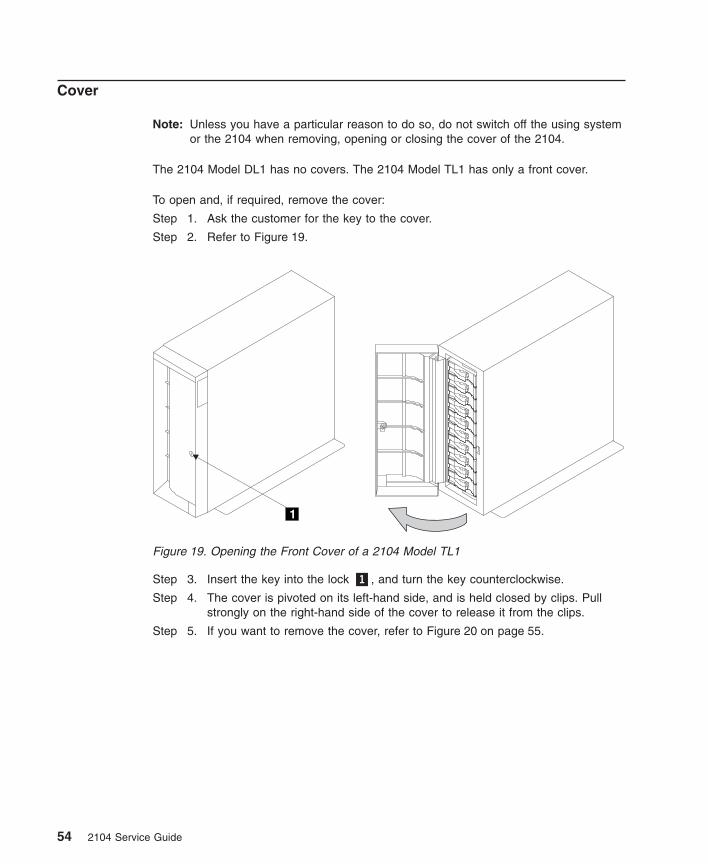
Cover
Note: Unless you have a particular reason to do so, do not switch off the using systemor the 2104 when removing, opening or closing the cover of the 2104.
The 2104 Model DL1 has no covers. The 2104 Model TL1 has only a front cover.
To open and, if required, remove the cover:
Step 1. Ask the customer for the key to the cover.
Step 2. Refer to Figure 19.
Step 3. Insert the key into the lock �1�, and turn the key counterclockwise.
Step 4. The cover is pivoted on its left-hand side, and is held closed by clips. Pullstrongly on the right-hand side of the cover to release it from the clips.
Step 5. If you want to remove the cover, refer to Figure 20 on page 55.
1
Figure 19. Opening the Front Cover of a 2104 Model TL1
54 2104 Service Guide
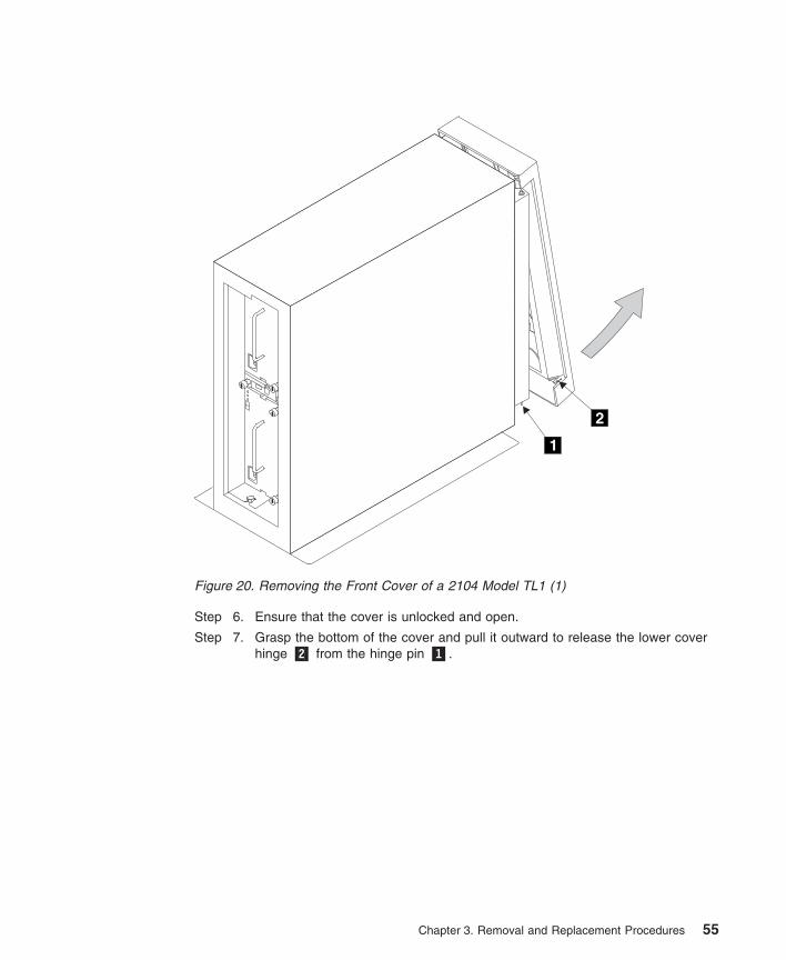
Step 6. Ensure that the cover is unlocked and open.
Step 7. Grasp the bottom of the cover and pull it outward to release the lower coverhinge �2� from the hinge pin �1�.
1
2
Figure 20. Removing the Front Cover of a 2104 Model TL1 (1)
Chapter 3. Removal and Replacement Procedures 55
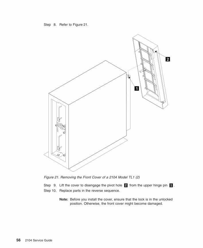
Step 8. Refer to Figure 21.
Step 9. Lift the cover to disengage the pivot hole �2� from the upper hinge pin �1�.
Step 10. Replace parts in the reverse sequence.
Note: Before you install the cover, ensure that the lock is in the unlockedposition. Otherwise, the front cover might become damaged.
1
2
Figure 21. Removing the Front Cover of a 2104 Model TL1 (2)
56 2104 Service Guide
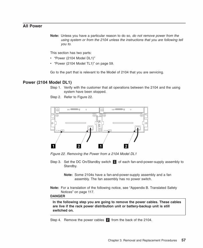
All Power
Note: Unless you have a particular reason to do so, do not remove power from theusing system or from the 2104 unless the instructions that you are following tellyou to.
This section has two parts:
v “Power (2104 Model DL1)”
v “Power (2104 Model TL1)” on page 59.
Go to the part that is relevant to the Model of 2104 that you are servicing.
Power (2104 Model DL1)Step 1. Verify with the customer that all operations between the 2104 and the using
system have been stopped.
Step 2. Refer to Figure 22.
Step 3. Set the DC On/Standby switch �1� of each fan-and-power-supply assembly toStandby.
Note: Some 2104s have a fan-and-power-supply assembly and a fanassembly. The fan assembly has no power switch.
Note: For a translation of the following notice, see “Appendix B. Translated SafetyNotices” on page 117.
DANGER
In the following step you are going to remove the power cables. These cablesare live if the rack power distribution unit or battery-backup unit is stillswitched on.
Step 4. Remove the power cables �2� from the back of the 2104.
1 12 2
Figure 22. Removing the Power from a 2104 Model DL1
Chapter 3. Removal and Replacement Procedures 57
Step 5. To return power to the 2104:
a. Reinstall the power cables �2�.
b. Set the DC On/Standby switch �1� of each fan-and-power-supply assemblyto On.
Note: The 2104 has no power sequencing. All the disk drive modules starttheir power sequence when the input voltages are inside the specifiedlimits. Their motors are started under control of the SCSI attachments inthe using system. To prevent the need for excessive electrical current,the disk drive module motors are not all started together. Normally, allthe disk drive module motors are running in less than 30 seconds fromthe time the 2104 is switched on.
58 2104 Service Guide
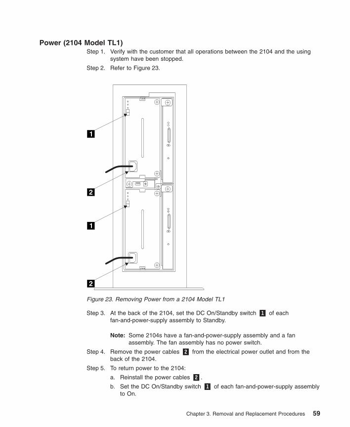
Power (2104 Model TL1)Step 1. Verify with the customer that all operations between the 2104 and the using
system have been stopped.
Step 2. Refer to Figure 23.
Step 3. At the back of the 2104, set the DC On/Standby switch �1� of eachfan-and-power-supply assembly to Standby.
Note: Some 2104s have a fan-and-power-supply assembly and a fanassembly. The fan assembly has no power switch.
Step 4. Remove the power cables �2� from the electrical power outlet and from theback of the 2104.
Step 5. To return power to the 2104:
a. Reinstall the power cables �2�.
b. Set the DC On/Standby switch �1� of each fan-and-power-supply assemblyto On.
1
1
2
2
Figure 23. Removing Power from a 2104 Model TL1
Chapter 3. Removal and Replacement Procedures 59
Note: The 2104 has no power sequencing. All the disk drive modules starttheir power sequence when the input voltages are inside the specifiedlimits. Their motors are started under control of the SCSI attachments inthe using system. To prevent the need for excessive electrical current,the disk drive module motors are not all started together. Normally, allthe disk drive module motors are running in less than 30 seconds fromthe time the 2104 is switched on.
60 2104 Service Guide
Disk Drive Modules and Dummy Disk Drive Modules
Note: A disk drive module is one FRU. Always exchange it as a complete FRU.
Removing a Module
Attention:
v Disk drive modules are electrostatic-discharge (ESD) sensitive. Use the tools andprocedures defined by your organization to protect such parts. See also “ElectrostaticDischarge” on page xiv.
v Disk drive modules are fragile. Handle them with care, and keep them well awayfrom strong magnetic fields.
v Any slot that has no disk drive module installed must contain a dummy disk drivemodule. The dummy module ensures that the correct airflow is maintained aroundthe disk drive modules in the other slots. If a slot remains empty, overheating mightoccur.
Notes:
1. Unless you have a particular reason to do so, do not switch off the using system orthe 2104 when removing disk drive modules or dummy disk drive modules.
2. The diagrams in these instructions show a 2104 Model DL1. The procedure for a2104 Model TL1 is the same, except that everything is turned through 90 degrees.
Step 1. If you are removing a module from a 2104 Model TL1, open the front cover(see “Cover” on page 54), if not already done.
Step 2. If you are removing a dummy disk drive module, go to step 3 on page 62.Otherwise, go to step 7 on page 63.
Chapter 3. Removal and Replacement Procedures 61
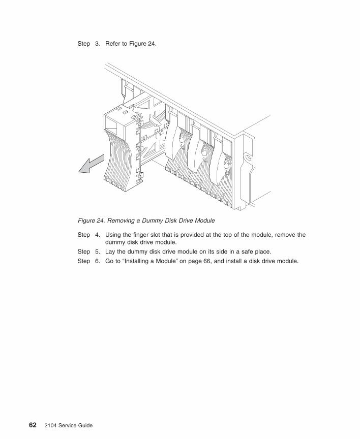
Step 3. Refer to Figure 24.
Step 4. Using the finger slot that is provided at the top of the module, remove thedummy disk drive module.
Step 5. Lay the dummy disk drive module on its side in a safe place.
Step 6. Go to “Installing a Module” on page 66, and install a disk drive module.
Figure 24. Removing a Dummy Disk Drive Module
62 2104 Service Guide
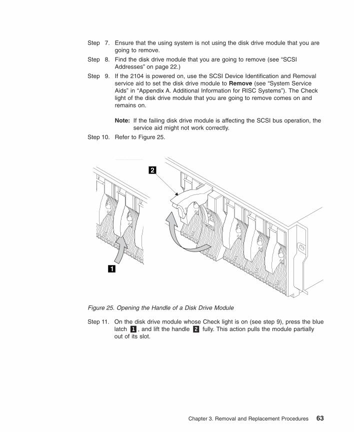
Step 7. Ensure that the using system is not using the disk drive module that you aregoing to remove.
Step 8. Find the disk drive module that you are going to remove (see “SCSIAddresses” on page 22.)
Step 9. If the 2104 is powered on, use the SCSI Device Identification and Removalservice aid to set the disk drive module to Remove (see “System ServiceAids” in “Appendix A. Additional Information for RISC Systems”). The Checklight of the disk drive module that you are going to remove comes on andremains on.
Note: If the failing disk drive module is affecting the SCSI bus operation, theservice aid might not work correctly.
Step 10. Refer to Figure 25.
Step 11. On the disk drive module whose Check light is on (see step 9), press the bluelatch �1�, and lift the handle �2� fully. This action pulls the module partiallyout of its slot.
1
2
Figure 25. Opening the Handle of a Disk Drive Module
Chapter 3. Removal and Replacement Procedures 63
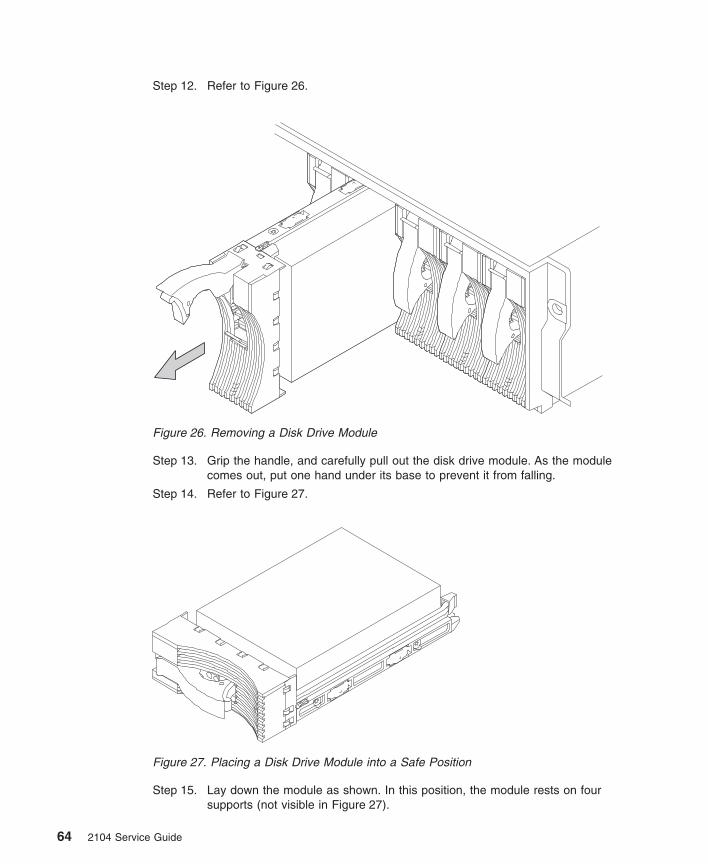
Step 12. Refer to Figure 26.
Step 13. Grip the handle, and carefully pull out the disk drive module. As the modulecomes out, put one hand under its base to prevent it from falling.
Step 14. Refer to Figure 27.
Step 15. Lay down the module as shown. In this position, the module rests on foursupports (not visible in Figure 27).
Figure 26. Removing a Disk Drive Module
Figure 27. Placing a Disk Drive Module into a Safe Position
64 2104 Service Guide
Step 16. Attention: Any slot that has no disk drive module installed must contain adummy disk drive module. The dummy module ensures that the correctairflow is maintained around the disk drive modules in the other slots. If a slotremains empty, overheating might occur.
Go to “Installing a Module” on page 66, and install a disk drive module or adummy disk drive module, as required.
Chapter 3. Removal and Replacement Procedures 65
Installing a Module
Attention:
v Disk drive modules are electrostatic-discharge (ESD) sensitive. Use the tools andprocedures defined by your organization to protect such parts. See also “ElectrostaticDischarge” on page xiv.
v Disk drive modules are fragile. Handle them with care, and keep them well awayfrom strong magnetic fields.
v Any slot that has no disk drive module installed must contain a dummy disk drivemodule. The dummy module ensures that the correct airflow is maintained aroundthe disk drive modules in the other slots. If a slot remains empty, overheating mightoccur.
Notes:
1. Unless you have a particular reason to do so, do not switch off the using system orthe 2104 when installing disk drive modules or dummy disk drive modules.
2. The diagrams in these instructions show a 2104 Model DL1. The procedure for a2104 Model TL1 is the same, except that everything is turned through 90 degrees.
66 2104 Service Guide
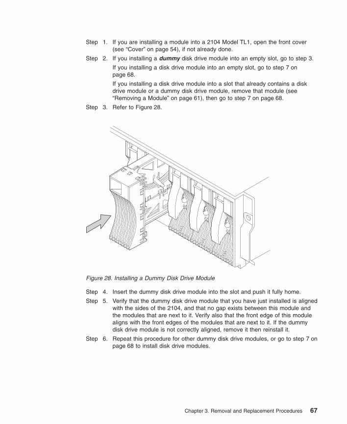
Step 1. If you are installing a module into a 2104 Model TL1, open the front cover(see “Cover” on page 54), if not already done.
Step 2. If you installing a dummy disk drive module into an empty slot, go to step 3.
If you installing a disk drive module into an empty slot, go to step 7 onpage 68.
If you installing a disk drive module into a slot that already contains a diskdrive module or a dummy disk drive module, remove that module (see“Removing a Module” on page 61), then go to step 7 on page 68.
Step 3. Refer to Figure 28.
Step 4. Insert the dummy disk drive module into the slot and push it fully home.
Step 5. Verify that the dummy disk drive module that you have just installed is alignedwith the sides of the 2104, and that no gap exists between this module andthe modules that are next to it. Verify also that the front edge of this modulealigns with the front edges of the modules that are next to it. If the dummydisk drive module is not correctly aligned, remove it then reinstall it.
Step 6. Repeat this procedure for other dummy disk drive modules, or go to step 7 onpage 68 to install disk drive modules.
Figure 28. Installing a Dummy Disk Drive Module
Chapter 3. Removal and Replacement Procedures 67
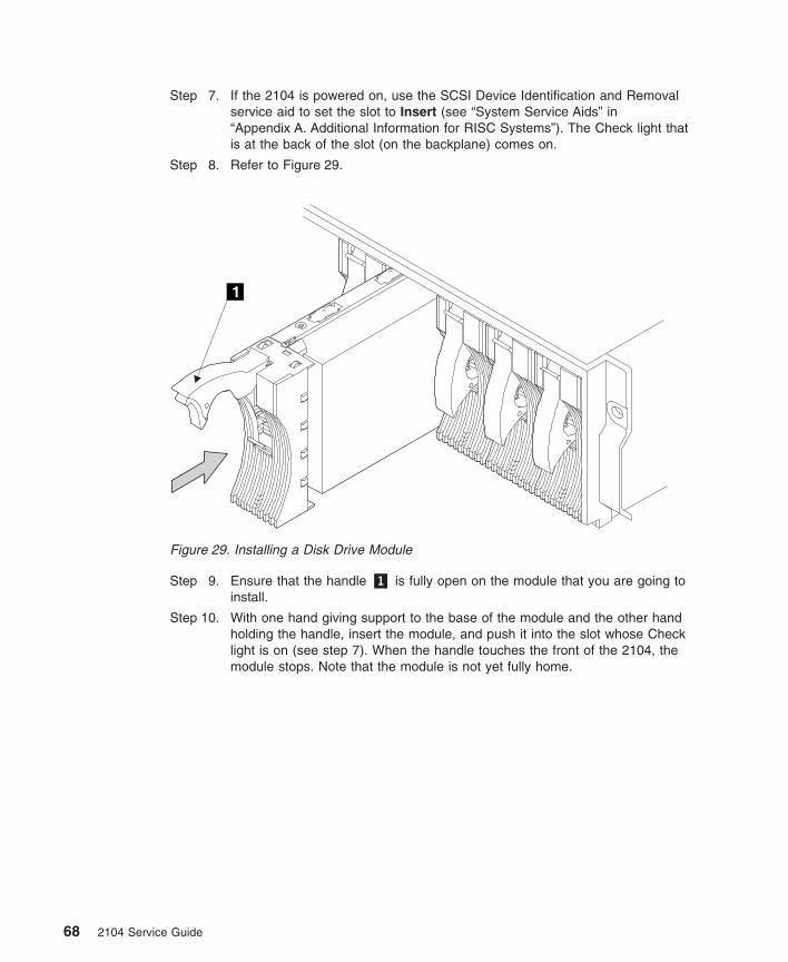
Step 7. If the 2104 is powered on, use the SCSI Device Identification and Removalservice aid to set the slot to Insert (see “System Service Aids” in“Appendix A. Additional Information for RISC Systems”). The Check light thatis at the back of the slot (on the backplane) comes on.
Step 8. Refer to Figure 29.
Step 9. Ensure that the handle �1� is fully open on the module that you are going toinstall.
Step 10. With one hand giving support to the base of the module and the other handholding the handle, insert the module, and push it into the slot whose Checklight is on (see step 7). When the handle touches the front of the 2104, themodule stops. Note that the module is not yet fully home.
Figure 29. Installing a Disk Drive Module
68 2104 Service Guide
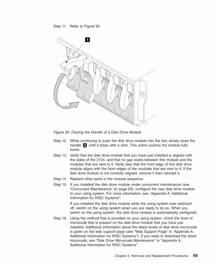
Step 11. Refer to Figure 30
Step 12. While continuing to push the disk drive module into the slot, slowly close thehandle �1� until it stops with a click. This action pushes the module fullyhome.
Step 13. Verify that the disk drive module that you have just installed is aligned withthe sides of the 2104, and that no gap exists between this module and themodules that are next to it. Verify also that the front edge of this disk drivemodule aligns with the front edges of the modules that are next to it. If thedisk drive module is not correctly aligned, remove it then reinstall it.
Step 14. Replace other parts in the reverse sequence.
Step 15. If you installed the disk drive module under concurrent maintenance (see“Concurrent Maintenance” on page 53), configure the new disk drive moduleto your using system. For more information, see “Appendix A. AdditionalInformation for RISC Systems”.
If you installed the disk drive module while the using system was switchedoff, switch on the using system when you are ready to do so. When youswitch on the using system, the disk drive module is automatically configured.
Step 16. Using the method that is provided on your using system, check the level ofmicrocode that is present on the disk drive module that you have justinstalled. Additional information about the latest levels of disk drive microcodeis given on the web support page (see “Web Support Page” in “Appendix A.Additional Information for RISC Systems”). If you need to download the latestmicrocode, see “Disk Drive Microcode Maintenance” in “Appendix A.Additional Information for RISC Systems”.
Figure 30. Closing the Handle of a Disk Drive Module
Chapter 3. Removal and Replacement Procedures 69
Step 17. If the 2104 is attached to a RISC system, go to step 18. Otherwise, go tostep 19.
Step 18. The disk drive that you have just installed has been configured with newhdisk numbers. If you want to change those numbers, go to “Configuring aDisk Drive Module to the Using System” in “Appendix A. AdditionalInformation for RISC Systems”. Otherwise, go to step 19.
Step 19. If you came to this section from a step in MAP, return to that step, andcontinue with the MAP. Otherwise, go to “MAP 2410: 2104 – RepairVerification” on page 52 to verify the repair.
70 2104 Service Guide
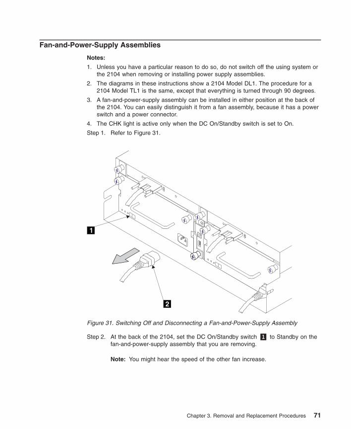
Fan-and-Power-Supply Assemblies
Notes:
1. Unless you have a particular reason to do so, do not switch off the using system orthe 2104 when removing or installing power supply assemblies.
2. The diagrams in these instructions show a 2104 Model DL1. The procedure for a2104 Model TL1 is the same, except that everything is turned through 90 degrees.
3. A fan-and-power-supply assembly can be installed in either position at the back ofthe 2104. You can easily distinguish it from a fan assembly, because it has a powerswitch and a power connector.
4. The CHK light is active only when the DC On/Standby switch is set to On.
Step 1. Refer to Figure 31.
Step 2. At the back of the 2104, set the DC On/Standby switch �1� to Standby on thefan-and-power-supply assembly that you are removing.
Note: You might hear the speed of the other fan increase.
1
2
Figure 31. Switching Off and Disconnecting a Fan-and-Power-Supply Assembly
Chapter 3. Removal and Replacement Procedures 71
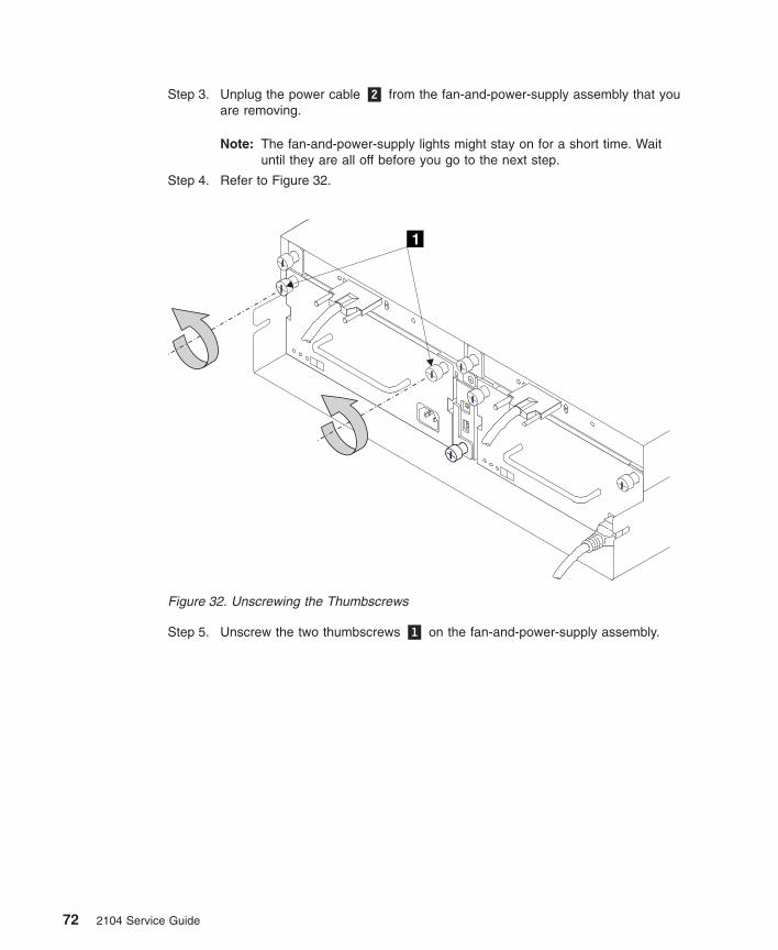
Step 3. Unplug the power cable �2� from the fan-and-power-supply assembly that youare removing.
Note: The fan-and-power-supply lights might stay on for a short time. Waituntil they are all off before you go to the next step.
Step 4. Refer to Figure 32.
Step 5. Unscrew the two thumbscrews �1� on the fan-and-power-supply assembly.
1
Figure 32. Unscrewing the Thumbscrews
72 2104 Service Guide
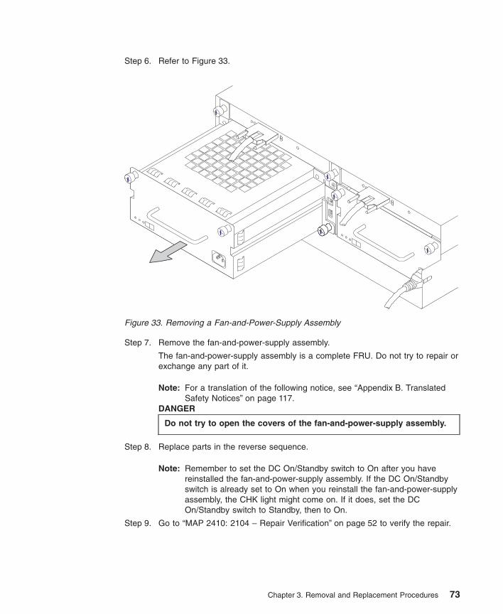
Step 6. Refer to Figure 33.
Step 7. Remove the fan-and-power-supply assembly.
The fan-and-power-supply assembly is a complete FRU. Do not try to repair orexchange any part of it.
Note: For a translation of the following notice, see “Appendix B. TranslatedSafety Notices” on page 117.
DANGER
Do not try to open the covers of the fan-and-power-supply assembly.
Step 8. Replace parts in the reverse sequence.
Note: Remember to set the DC On/Standby switch to On after you havereinstalled the fan-and-power-supply assembly. If the DC On/Standbyswitch is already set to On when you reinstall the fan-and-power-supplyassembly, the CHK light might come on. If it does, set the DCOn/Standby switch to Standby, then to On.
Step 9. Go to “MAP 2410: 2104 – Repair Verification” on page 52 to verify the repair.
Figure 33. Removing a Fan-and-Power-Supply Assembly
Chapter 3. Removal and Replacement Procedures 73
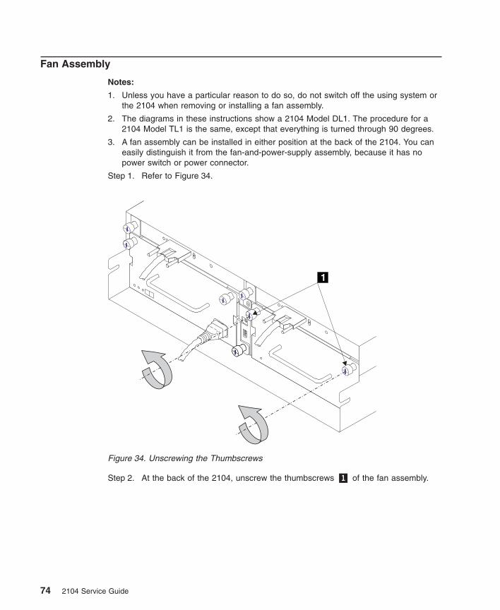
Fan Assembly
Notes:
1. Unless you have a particular reason to do so, do not switch off the using system orthe 2104 when removing or installing a fan assembly.
2. The diagrams in these instructions show a 2104 Model DL1. The procedure for a2104 Model TL1 is the same, except that everything is turned through 90 degrees.
3. A fan assembly can be installed in either position at the back of the 2104. You caneasily distinguish it from the fan-and-power-supply assembly, because it has nopower switch or power connector.
Step 1. Refer to Figure 34.
Step 2. At the back of the 2104, unscrew the thumbscrews �1� of the fan assembly.
1
Figure 34. Unscrewing the Thumbscrews
74 2104 Service Guide
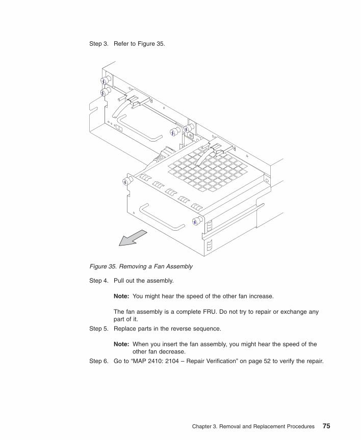
Step 3. Refer to Figure 35.
Step 4. Pull out the assembly.
Note: You might hear the speed of the other fan increase.
The fan assembly is a complete FRU. Do not try to repair or exchange anypart of it.
Step 5. Replace parts in the reverse sequence.
Note: When you insert the fan assembly, you might hear the speed of theother fan decrease.
Step 6. Go to “MAP 2410: 2104 – Repair Verification” on page 52 to verify the repair.
Figure 35. Removing a Fan Assembly
Chapter 3. Removal and Replacement Procedures 75
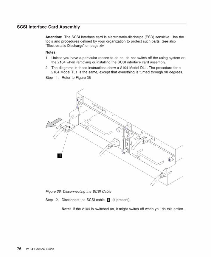
SCSI Interface Card Assembly
Attention: The SCSI interface card is electrostatic-discharge (ESD) sensitive. Use thetools and procedures defined by your organization to protect such parts. See also“Electrostatic Discharge” on page xiv.
Notes:
1. Unless you have a particular reason to do so, do not switch off the using system orthe 2104 when removing or installing the SCSI interface card assembly.
2. The diagrams in these instructions show a 2104 Model DL1. The procedure for a2104 Model TL1 is the same, except that everything is turned through 90 degrees.
Step 1. Refer to Figure 36
Step 2. Disconnect the SCSI cable �1� (if present).
Note: If the 2104 is switched on, it might switch off when you do this action.
1
Figure 36. Disconnecting the SCSI Cable
76 2104 Service Guide
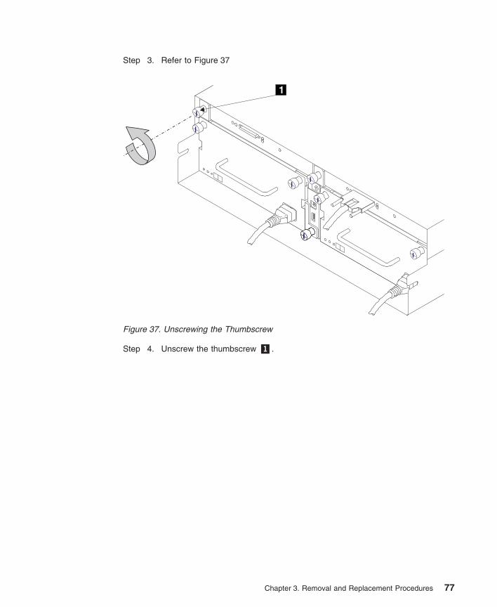
Step 3. Refer to Figure 37
Step 4. Unscrew the thumbscrew �1�.
1
Figure 37. Unscrewing the Thumbscrew
Chapter 3. Removal and Replacement Procedures 77
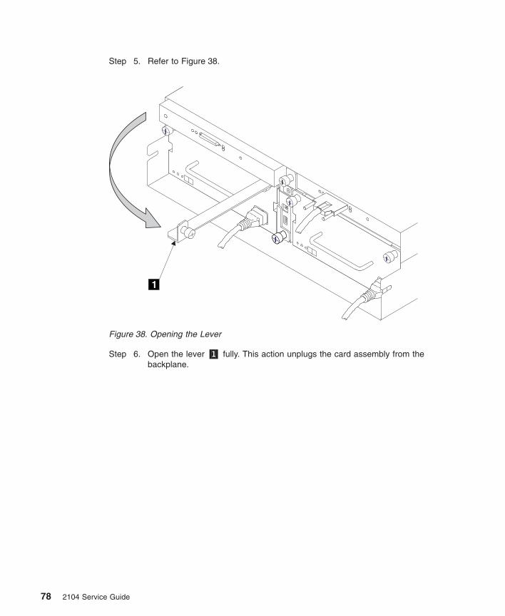
Step 5. Refer to Figure 38.
Step 6. Open the lever �1� fully. This action unplugs the card assembly from thebackplane.
1
Figure 38. Opening the Lever
78 2104 Service Guide
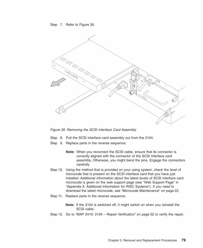
Step 7. Refer to Figure 39.
Step 8. Pull the SCSI interface card assembly out from the 2104.
Step 9. Replace parts in the reverse sequence.
Note: When you reconnect the SCSI cable, ensure that its connector iscorrectly aligned with the connector of the SCSI interface cardassembly. Otherwise, you might bend the pins. Engage the connectorscarefully.
Step 10. Using the method that is provided on your using system, check the level ofmicrocode that is present on the SCSI interface card that you have justinstalled. Additional information about the latest levels of SCSI interface cardmicrocode is given on the web support page (see “Web Support Page” in“Appendix A. Additional Information for RISC Systems”). If you need todownload the latest microcode, see “Microcode Maintenance” on page 22.
Step 11. Replace parts in the reverse sequence.
Note: If the 2104 is switched off, it might switch on when you reinstall theSCSI cable.
Step 12. Go to “MAP 2410: 2104 – Repair Verification” on page 52 to verify the repair.
Figure 39. Removing the SCSI Interface Card Assembly
Chapter 3. Removal and Replacement Procedures 79
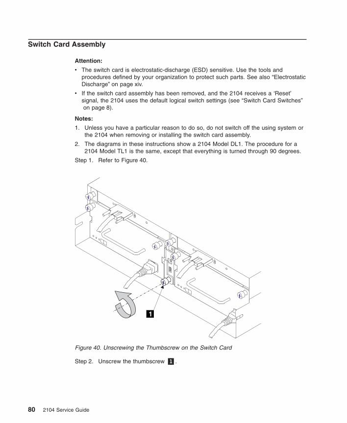
Switch Card Assembly
Attention:
v The switch card is electrostatic-discharge (ESD) sensitive. Use the tools andprocedures defined by your organization to protect such parts. See also “ElectrostaticDischarge” on page xiv.
v If the switch card assembly has been removed, and the 2104 receives a ‘Reset’signal, the 2104 uses the default logical switch settings (see “Switch Card Switches”on page 8).
Notes:
1. Unless you have a particular reason to do so, do not switch off the using system orthe 2104 when removing or installing the switch card assembly.
2. The diagrams in these instructions show a 2104 Model DL1. The procedure for a2104 Model TL1 is the same, except that everything is turned through 90 degrees.
Step 1. Refer to Figure 40.
Step 2. Unscrew the thumbscrew �1�.
1
Figure 40. Unscrewing the Thumbscrew on the Switch Card
80 2104 Service Guide
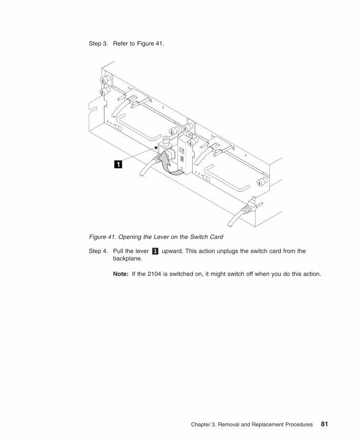
Step 3. Refer to Figure 41.
Step 4. Pull the lever �1� upward. This action unplugs the switch card from thebackplane.
Note: If the 2104 is switched on, it might switch off when you do this action.
1
Figure 41. Opening the Lever on the Switch Card
Chapter 3. Removal and Replacement Procedures 81
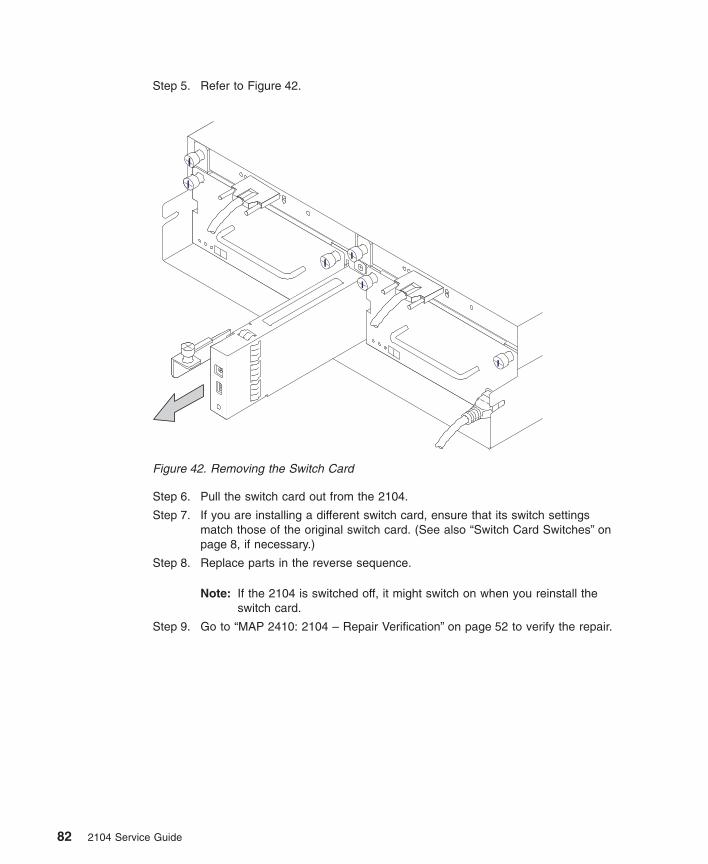
Step 5. Refer to Figure 42.
Step 6. Pull the switch card out from the 2104.
Step 7. If you are installing a different switch card, ensure that its switch settingsmatch those of the original switch card. (See also “Switch Card Switches” onpage 8, if necessary.)
Step 8. Replace parts in the reverse sequence.
Note: If the 2104 is switched off, it might switch on when you reinstall theswitch card.
Step 9. Go to “MAP 2410: 2104 – Repair Verification” on page 52 to verify the repair.
Figure 42. Removing the Switch Card
82 2104 Service Guide
Frame Assembly
Notes:
1. Use this procedure only if you are exchanging the frame of the 2104. If you areremoving a complete 2104 Model DL1 from the rack (for example, to locate itelsewhere), go to “Removing a 2104 Model DL1 from a Rack” on page 91.
2. You will need another person to help you remove the frame from the rack.
Attention: Unless the using system needs to be switched off for some other reason, donot switch off the using system when servicing the 2104. Power cables and externalSCSI cables that connect the 2104 to the using system can be disconnected while thatsystem is running.
Step 1. Verify with the customer that all operations between the 2104 and the usingsystem have been stopped.
Step 2. Remove power from the 2104 (see “All Power” on page 57).
Step 3. For the 2104 Model TL1, open the front cover (see “Cover” on page 54).
Step 4. Carefully make a note of the locations of the disk drive modules and (ifpresent) dummy disk drive modules that are in the 2104. This action ensuresthat you reinstall the modules into their original slots. It is recommended thatyou attach identifying labels to the modules.
Step 5. Remove all the disk drive modules and dummy disk drive modules (see“Removing a Module” on page 61).
Step 6. Remove the fan-and-power-supply assemblies, or fan assembly andfan-and-power-supply assembly, from the back of the 2104 (see“Fan-and-Power-Supply Assemblies” on page 71 and, if required, “FanAssembly” on page 74).
Step 7. Make a note of which SCSI cable (if present) is connected to each particularSCSI interface card.
Step 8. Disconnect the external SCSI cables (if present) from the SCSI interfacecards.
Step 9. Attention: The SCSI interface card assemblies must be installed into thesame positions in the new frame assembly as those in which they are nowinstalled in the original frame assembly.
Make a note of the positions of the SCSI interface card assemblies beforeyou remove them. Attach labels if necessary.
Step 10. Remove the SCSI interface card assemblies (see “SCSI Interface CardAssembly” on page 76).
Step 11. If you are removing the frame assembly of a 2104 Model DL1, go to “2104Model DL1” on page 84.
If you are removing the frame assembly of a 2104 Model TL1, go to “2104Model TL1” on page 88.
Chapter 3. Removal and Replacement Procedures 83
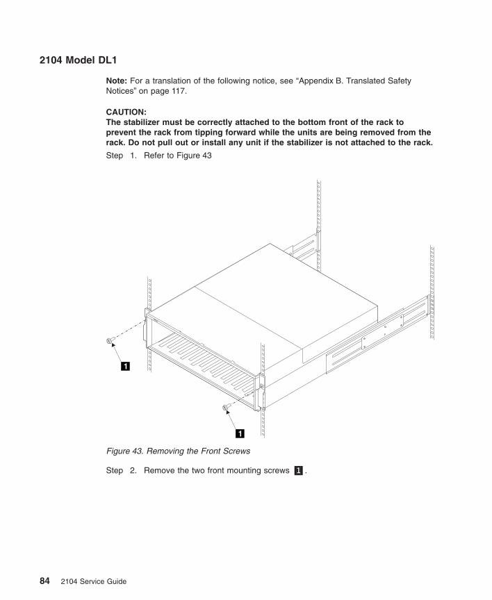
2104 Model DL1
Note: For a translation of the following notice, see “Appendix B. Translated SafetyNotices” on page 117.
CAUTION:The stabilizer must be correctly attached to the bottom front of the rack toprevent the rack from tipping forward while the units are being removed from therack. Do not pull out or install any unit if the stabilizer is not attached to the rack.
Step 1. Refer to Figure 43
Step 2. Remove the two front mounting screws �1�.
1
1
Figure 43. Removing the Front Screws
84 2104 Service Guide
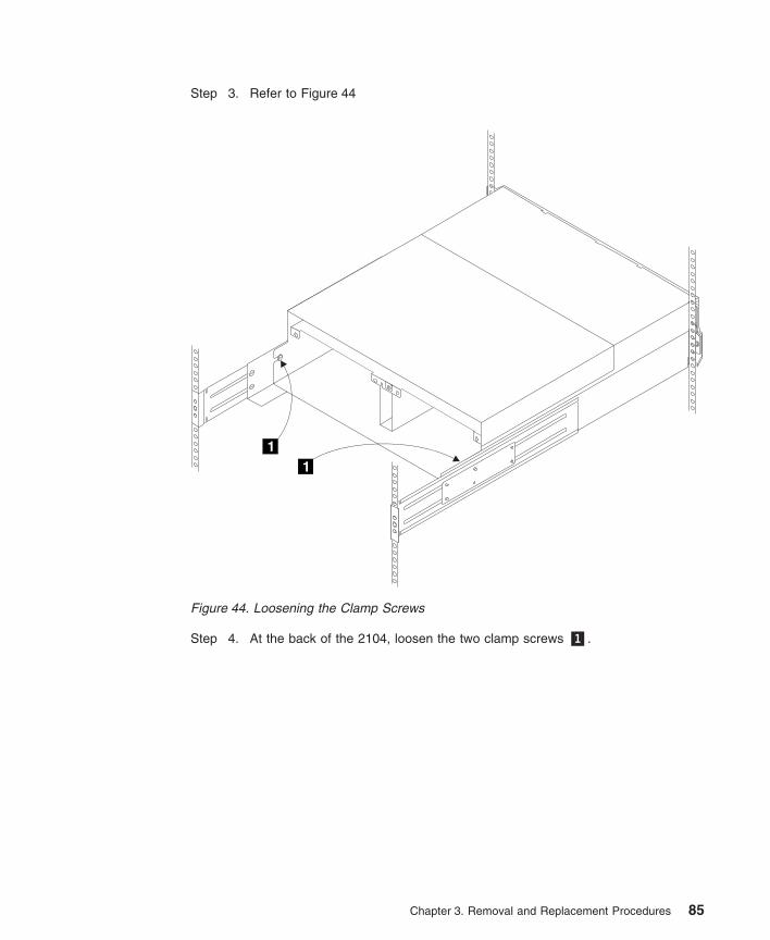
Step 3. Refer to Figure 44
Step 4. At the back of the 2104, loosen the two clamp screws �1�.
11
Figure 44. Loosening the Clamp Screws
Chapter 3. Removal and Replacement Procedures 85
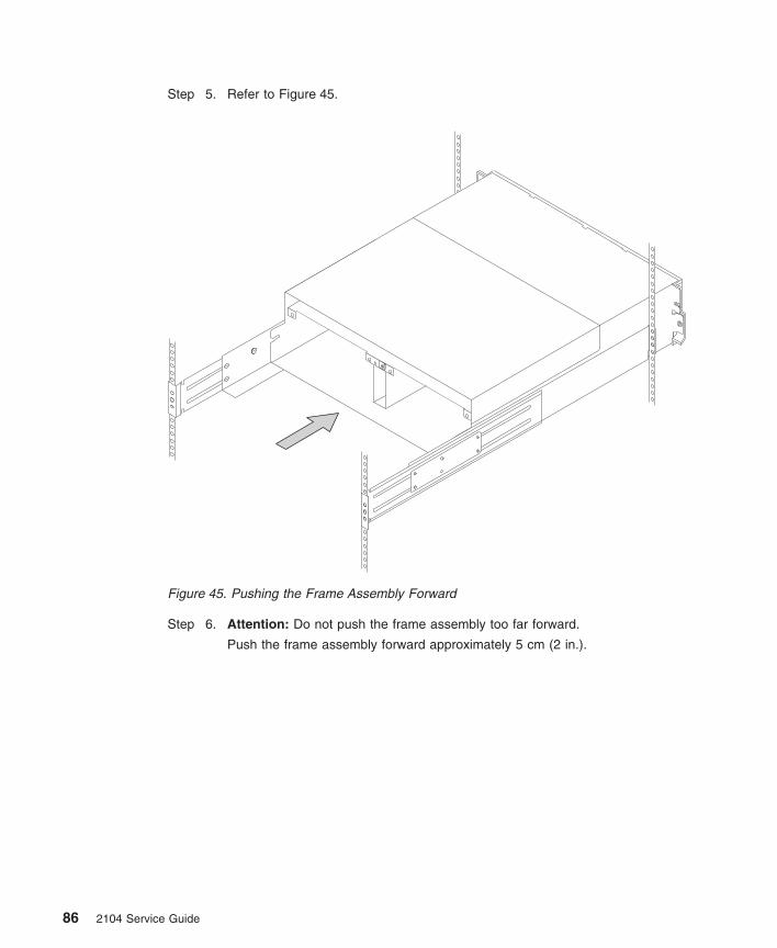
Step 5. Refer to Figure 45.
Step 6. Attention: Do not push the frame assembly too far forward.
Push the frame assembly forward approximately 5 cm (2 in.).
Figure 45. Pushing the Frame Assembly Forward
86 2104 Service Guide
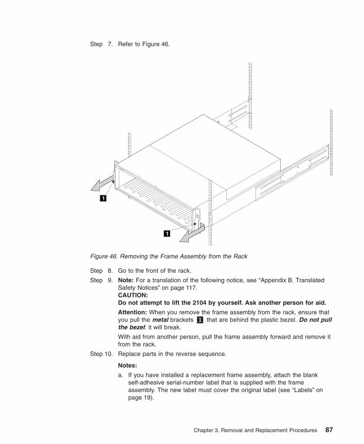
Step 7. Refer to Figure 46.
Step 8. Go to the front of the rack.
Step 9. Note: For a translation of the following notice, see “Appendix B. TranslatedSafety Notices” on page 117.CAUTION:Do not attempt to lift the 2104 by yourself. Ask another person for aid.
Attention: When you remove the frame assembly from the rack, ensure thatyou pull the metal brackets �1� that are behind the plastic bezel. Do not pullthe bezel: it will break.
With aid from another person, pull the frame assembly forward and remove itfrom the rack.
Step 10. Replace parts in the reverse sequence.
Notes:
a. If you have installed a replacement frame assembly, attach the blankself-adhesive serial-number label that is supplied with the frameassembly. The new label must cover the original label (see “Labels” onpage 19).
1
1
Figure 46. Removing the Frame Assembly from the Rack
Chapter 3. Removal and Replacement Procedures 87
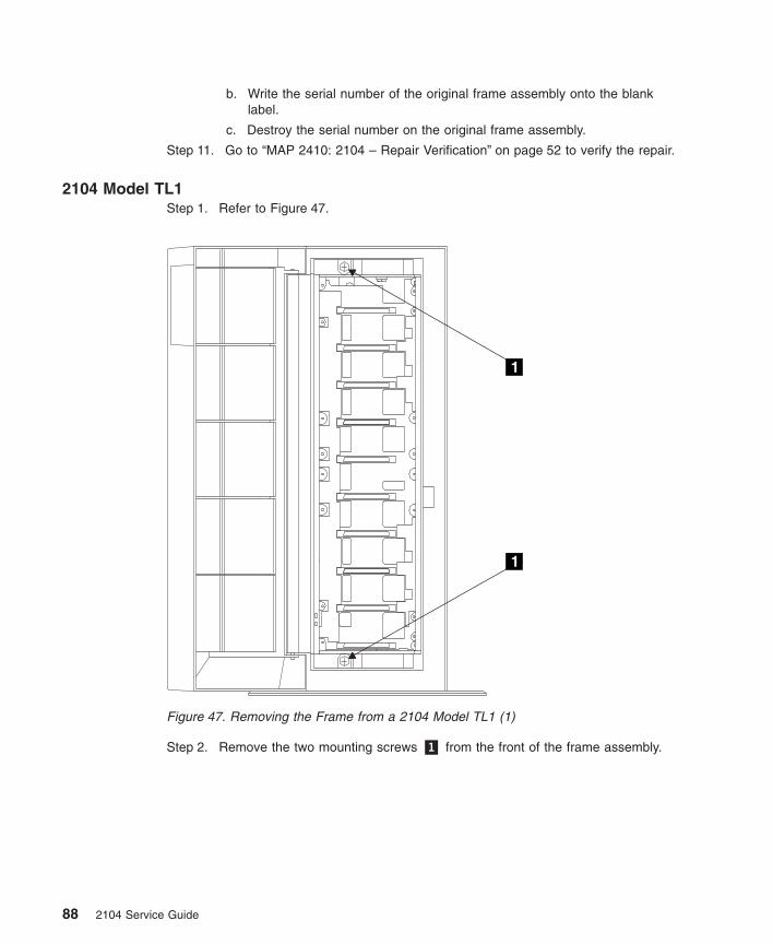
b. Write the serial number of the original frame assembly onto the blanklabel.
c. Destroy the serial number on the original frame assembly.
Step 11. Go to “MAP 2410: 2104 – Repair Verification” on page 52 to verify the repair.
2104 Model TL1Step 1. Refer to Figure 47.
Step 2. Remove the two mounting screws �1� from the front of the frame assembly.
11
11
Figure 47. Removing the Frame from a 2104 Model TL1 (1)
88 2104 Service Guide
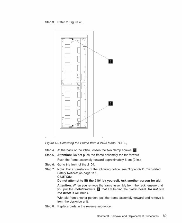
Step 3. Refer to Figure 48.
Step 4. At the back of the 2104, loosen the two clamp screws �1�.
Step 5. Attention: Do not push the frame assembly too far forward.
Push the frame assembly forward approximately 5 cm (2 in.).
Step 6. Go to the front of the 2104.
Step 7. Note: For a translation of the following notice, see “Appendix B. TranslatedSafety Notices” on page 117.CAUTION:Do not attempt to lift the 2104 by yourself. Ask another person for aid.
Attention: When you remove the frame assembly from the rack, ensure thatyou pull the metal brackets �1� that are behind the plastic bezel. Do not pullthe bezel: it will break.
With aid from another person, pull the frame assembly forward and remove itfrom the deskside unit.
Step 8. Replace parts in the reverse sequence.
11
11
Figure 48. Removing the Frame from a 2104 Model TL1 (2)
Chapter 3. Removal and Replacement Procedures 89
Notes:
a. If you have installed a replacement frame assembly, attach the blankself-adhesive serial-number label that is supplied with the frame assembly.The new label must cover the original label (see “Labels” on page 19).
b. Write the serial number of the original frame assembly onto the blank label.
c. Destroy the serial number on the original frame assembly.
Step 9. Go to “MAP 2410: 2104 – Repair Verification” on page 52 to verify the repair.
90 2104 Service Guide
Removing a 2104 Model DL1 from a Rack
Notes:
1. Use this procedure only if you are removing a complete 2104 Model DL1 fromthe rack (for example, to locate it elsewhere). If you are exchanging the frame ofthe 2104, go to “Frame Assembly” on page 83.
2. You will need another person to help you remove the 2104 from the rack.
Attention: Unless the using system needs to be switched off for some other reason, donot switch off the using system when servicing the 2104. Power cables and externalSCSI cables that connect the 2104 to the using system can be disconnected while thatsystem is running.
Step 1. If not already done:
a. Verify with the customer that all operations between the 2104 and theusing system have been stopped.
b. If applicable, unconfigure the 2104 from the using system. For moreinformation, see “Unconfiguring a 2104 from the Using System” in“Appendix A. Additional Information for RISC Systems”.
c. Make a note of the positions of the external SCSI cables that areconnected at the back of the 2104.
d. Disconnect the external SCSI cables from the back of the 2104.
e. Remove all power from the 2104 (see “All Power” on page 57).
Step 2. Note: For a translation of the following notice, see “Appendix B. TranslatedSafety Notices” on page 117.CAUTION:
v The stabilizer must be correctly attached to the bottom front of therack to prevent the rack from tipping forward while the units are beingremoved from the rack. Do not pull out or install any unit if thestabilizer is not attached to the rack.
v A 2104 Model DL1 weighs up to 38.5 kg (85 lb) with disk drive modulesinstalled. Do not attempt to remove the 2104 from the rack unless allthe disk drive modules have been removed.
You are now going to remove all the disk drive modules and (if present)dummy disk drive modules from the 2104. If the 2104 is to be used later withits disk drive modules configured as they are now, carefully make a note of thelocations of the disk drive modules and dummy disk drive modules before youstart to remove them. This action ensures that you reinstall the modules intotheir original slots. It is recommended that you attach identifying labels to themodules.
Step 3. Remove the all the disk drive modules (see “Disk Drive Modules and DummyDisk Drive Modules” on page 61).
Chapter 3. Removal and Replacement Procedures 91
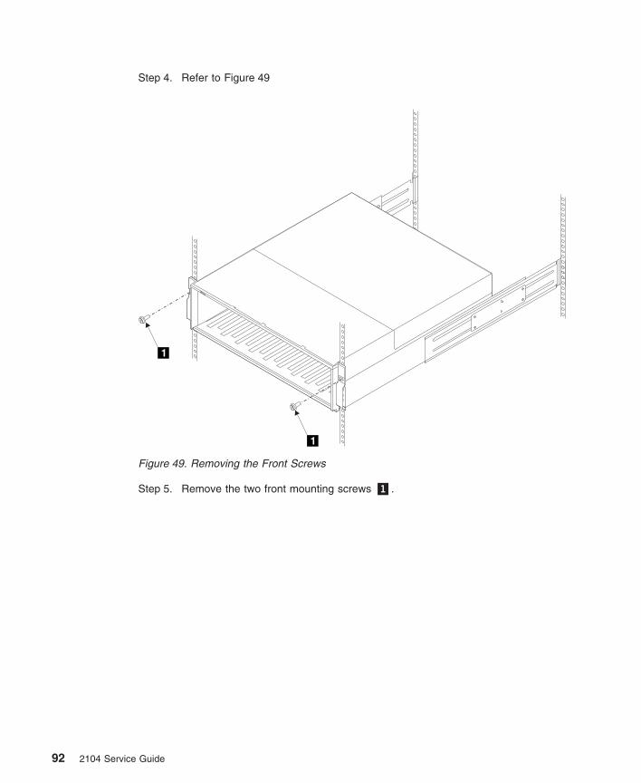
Step 4. Refer to Figure 49
Step 5. Remove the two front mounting screws �1�.
1
1
Figure 49. Removing the Front Screws
92 2104 Service Guide
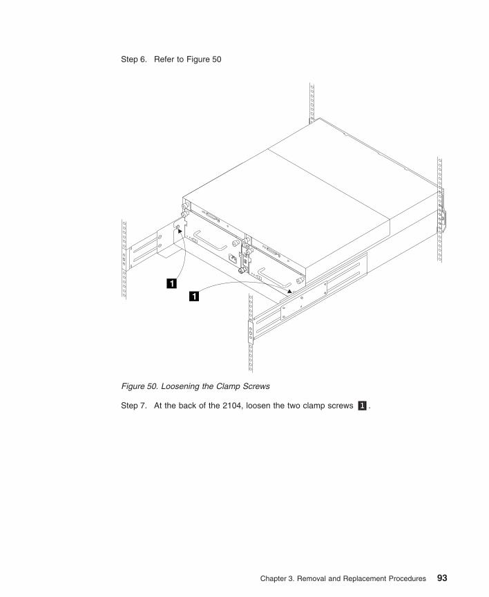
Step 6. Refer to Figure 50
Step 7. At the back of the 2104, loosen the two clamp screws �1�.
11
Figure 50. Loosening the Clamp Screws
Chapter 3. Removal and Replacement Procedures 93
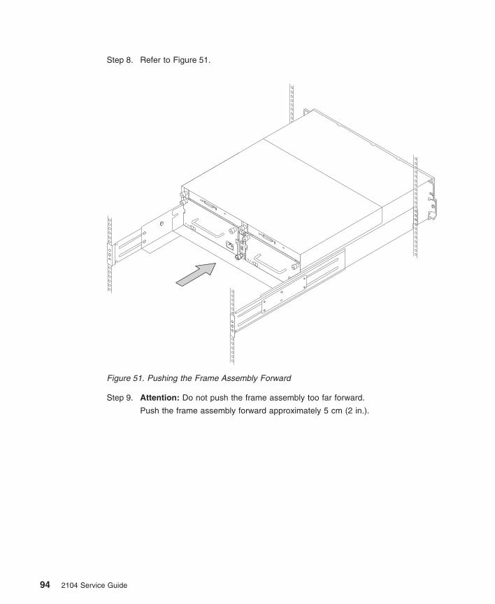
Step 8. Refer to Figure 51.
Step 9. Attention: Do not push the frame assembly too far forward.
Push the frame assembly forward approximately 5 cm (2 in.).
Figure 51. Pushing the Frame Assembly Forward
94 2104 Service Guide
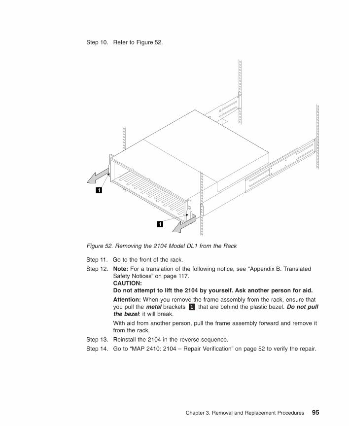
Step 10. Refer to Figure 52.
Step 11. Go to the front of the rack.
Step 12. Note: For a translation of the following notice, see “Appendix B. TranslatedSafety Notices” on page 117.CAUTION:Do not attempt to lift the 2104 by yourself. Ask another person for aid.
Attention: When you remove the frame assembly from the rack, ensure thatyou pull the metal brackets �1� that are behind the plastic bezel. Do not pullthe bezel: it will break.
With aid from another person, pull the frame assembly forward and remove itfrom the rack.
Step 13. Reinstall the 2104 in the reverse sequence.
Step 14. Go to “MAP 2410: 2104 – Repair Verification” on page 52 to verify the repair.
1
1
Figure 52. Removing the 2104 Model DL1 from the Rack
Chapter 3. Removal and Replacement Procedures 95
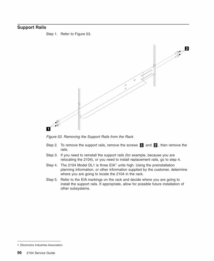
Support RailsStep 1. Refer to Figure 53.
Step 2. To remove the support rails, remove the screws �1� and �2�, then remove therails.
Step 3. If you need to reinstall the support rails (for example, because you arerelocating the 2104), or you need to install replacement rails, go to step 4.
Step 4. The 2104 Model DL1 is three EIA1 units high. Using the preinstallationplanning information, or other information supplied by the customer, determinewhere you are going to locate the 2104 in the rack.
Step 5. Refer to the EIA markings on the rack and decide where you are going toinstall the support rails. If appropriate, allow for possible future installation ofother subsystems.
1. Electronics Industries Association.
5
7
61
2
Figure 53. Removing the Support Rails from the Rack
96 2104 Service Guide
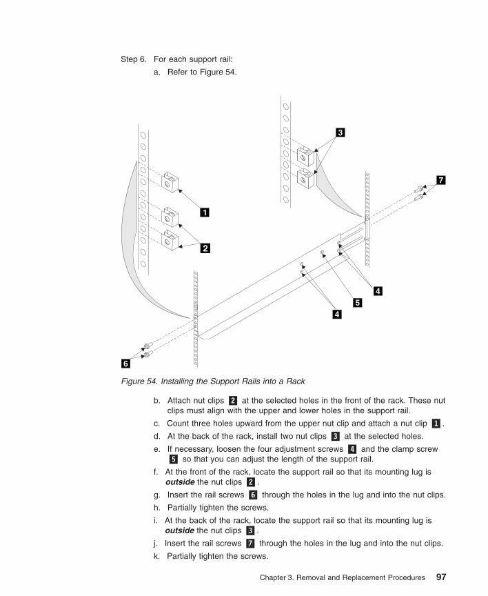
Step 6. For each support rail:
a. Refer to Figure 54.
b. Attach nut clips �2� at the selected holes in the front of the rack. These nutclips must align with the upper and lower holes in the support rail.
c. Count three holes upward from the upper nut clip and attach a nut clip �1�.
d. At the back of the rack, install two nut clips �3� at the selected holes.
e. If necessary, loosen the four adjustment screws �4� and the clamp screw�5� so that you can adjust the length of the support rail.
f. At the front of the rack, locate the support rail so that its mounting lug isoutside the nut clips �2�.
g. Insert the rail screws �6� through the holes in the lug and into the nut clips.
h. Partially tighten the screws.
i. At the back of the rack, locate the support rail so that its mounting lug isoutside the nut clips �3�.
j. Insert the rail screws �7� through the holes in the lug and into the nut clips.
k. Partially tighten the screws.
4
45
7
6
3
2
1
Figure 54. Installing the Support Rails into a Rack
Chapter 3. Removal and Replacement Procedures 97
l. Check whether the support rail is horizontal (a spirit level might be usefulhere). If the rail is not horizontal, relocate it as necessary.
m. Fully tighten the front and back rail screws.
n. Fully tighten the four adjustment screws �4�. Do not tighten the clampscrew �5�. The screw must be loose to allow the installation of the 2104.)
98 2104 Service Guide
Chapter 4. Parts Catalog
This parts catalog gives part numbers for the parts and FRUs of the 2104 Model DL1and 2104 Model TL1.
Conventions
AR in the units column of the parts list denotes that the quantity used is asrequired.
99
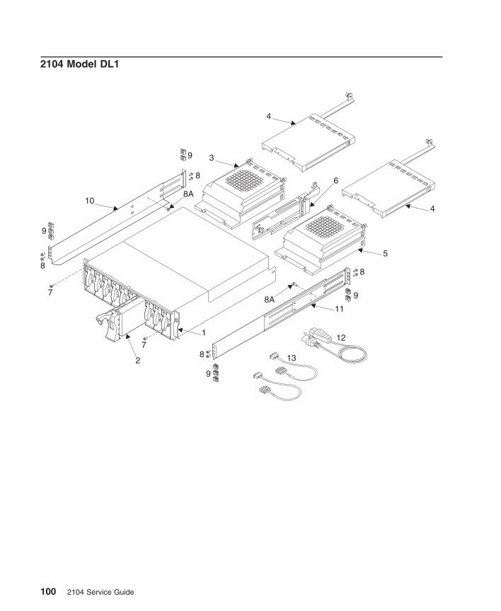
2104 Model DL1
9
9
9
9
8
8
8
8
13
12
11
4
4
6
10
1
2
3
5
7
7
8A
8A
100 2104 Service Guide
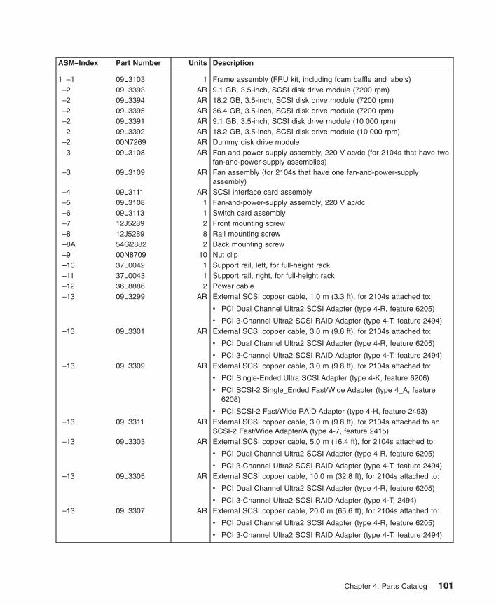
ASM–Index Part Number Units Description
1 –1 09L3103 1 Frame assembly (FRU kit, including foam baffle and labels)–2 09L3393 AR 9.1 GB, 3.5-inch, SCSI disk drive module (7200 rpm)–2 09L3394 AR 18.2 GB, 3.5-inch, SCSI disk drive module (7200 rpm)–2 09L3395 AR 36.4 GB, 3.5-inch, SCSI disk drive module (7200 rpm)–2 09L3391 AR 9.1 GB, 3.5-inch, SCSI disk drive module (10 000 rpm)–2 09L3392 AR 18.2 GB, 3.5-inch, SCSI disk drive module (10 000 rpm)–2 00N7269 AR Dummy disk drive module–3 09L3108 AR Fan-and-power-supply assembly, 220 V ac/dc (for 2104s that have two
fan-and-power-supply assemblies)–3 09L3109 AR Fan assembly (for 2104s that have one fan-and-power-supply
assembly)–4 09L3111 AR SCSI interface card assembly–5 09L3108 1 Fan-and-power-supply assembly, 220 V ac/dc–6 09L3113 1 Switch card assembly–7 12J5289 2 Front mounting screw–8 12J5289 8 Rail mounting screw–8A 54G2882 2 Back mounting screw–9 00N8709 10 Nut clip–10 37L0042 1 Support rail, left, for full-height rack–11 37L0043 1 Support rail, right, for full-height rack–12 36L8886 2 Power cable–13 09L3299 AR External SCSI copper cable, 1.0 m (3.3 ft), for 2104s attached to:
v PCI Dual Channel Ultra2 SCSI Adapter (type 4-R, feature 6205)
v PCI 3-Channel Ultra2 SCSI RAID Adapter (type 4-T, feature 2494)–13 09L3301 AR External SCSI copper cable, 3.0 m (9.8 ft), for 2104s attached to:
v PCI Dual Channel Ultra2 SCSI Adapter (type 4-R, feature 6205)
v PCI 3-Channel Ultra2 SCSI RAID Adapter (type 4-T, feature 2494)–13 09L3309 AR External SCSI copper cable, 3.0 m (9.8 ft), for 2104s attached to:
v PCI Single-Ended Ultra SCSI Adapter (type 4-K, feature 6206)
v PCI SCSI-2 Single_Ended Fast/Wide Adapter (type 4_A, feature6208)
v PCI SCSI-2 Fast/Wide RAID Adapter (type 4-H, feature 2493)–13 09L3311 AR External SCSI copper cable, 3.0 m (9.8 ft), for 2104s attached to an
SCSI-2 Fast/Wide Adapter/A (type 4-7, feature 2415)–13 09L3303 AR External SCSI copper cable, 5.0 m (16.4 ft), for 2104s attached to:
v PCI Dual Channel Ultra2 SCSI Adapter (type 4-R, feature 6205)
v PCI 3-Channel Ultra2 SCSI RAID Adapter (type 4-T, feature 2494)–13 09L3305 AR External SCSI copper cable, 10.0 m (32.8 ft), for 2104s attached to:
v PCI Dual Channel Ultra2 SCSI Adapter (type 4-R, feature 6205)
v PCI 3-Channel Ultra2 SCSI RAID Adapter (type 4-T, 2494)–13 09L3307 AR External SCSI copper cable, 20.0 m (65.6 ft), for 2104s attached to:
v PCI Dual Channel Ultra2 SCSI Adapter (type 4-R, feature 6205)
v PCI 3-Channel Ultra2 SCSI RAID Adapter (type 4-T, feature 2494)
Chapter 4. Parts Catalog 101
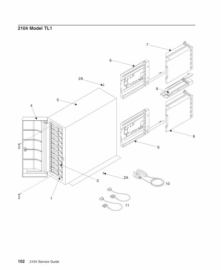
2104 Model TL1
8
9
1
3
6
6
7
5
4
2
2
2A
2A
11
10
102 2104 Service Guide
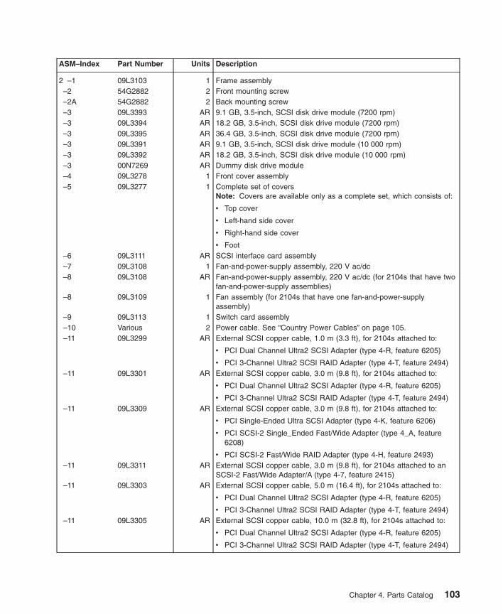
ASM–Index Part Number Units Description
2 –1 09L3103 1 Frame assembly–2 54G2882 2 Front mounting screw–2A 54G2882 2 Back mounting screw–3 09L3393 AR 9.1 GB, 3.5-inch, SCSI disk drive module (7200 rpm)–3 09L3394 AR 18.2 GB, 3.5-inch, SCSI disk drive module (7200 rpm)–3 09L3395 AR 36.4 GB, 3.5-inch, SCSI disk drive module (7200 rpm)–3 09L3391 AR 9.1 GB, 3.5-inch, SCSI disk drive module (10 000 rpm)–3 09L3392 AR 18.2 GB, 3.5-inch, SCSI disk drive module (10 000 rpm)–3 00N7269 AR Dummy disk drive module–4 09L3278 1 Front cover assembly–5 09L3277 1 Complete set of covers
Note: Covers are available only as a complete set, which consists of:
v Top cover
v Left-hand side cover
v Right-hand side cover
v Foot–6 09L3111 AR SCSI interface card assembly–7 09L3108 1 Fan-and-power-supply assembly, 220 V ac/dc–8 09L3108 AR Fan-and-power-supply assembly, 220 V ac/dc (for 2104s that have two
fan-and-power-supply assemblies)–8 09L3109 1 Fan assembly (for 2104s that have one fan-and-power-supply
assembly)–9 09L3113 1 Switch card assembly–10 Various 2 Power cable. See “Country Power Cables” on page 105.–11 09L3299 AR External SCSI copper cable, 1.0 m (3.3 ft), for 2104s attached to:
v PCI Dual Channel Ultra2 SCSI Adapter (type 4-R, feature 6205)
v PCI 3-Channel Ultra2 SCSI RAID Adapter (type 4-T, feature 2494)–11 09L3301 AR External SCSI copper cable, 3.0 m (9.8 ft), for 2104s attached to:
v PCI Dual Channel Ultra2 SCSI Adapter (type 4-R, feature 6205)
v PCI 3-Channel Ultra2 SCSI RAID Adapter (type 4-T, feature 2494)–11 09L3309 AR External SCSI copper cable, 3.0 m (9.8 ft), for 2104s attached to:
v PCI Single-Ended Ultra SCSI Adapter (type 4-K, feature 6206)
v PCI SCSI-2 Single_Ended Fast/Wide Adapter (type 4_A, feature6208)
v PCI SCSI-2 Fast/Wide RAID Adapter (type 4-H, feature 2493)–11 09L3311 AR External SCSI copper cable, 3.0 m (9.8 ft), for 2104s attached to an
SCSI-2 Fast/Wide Adapter/A (type 4-7, feature 2415)–11 09L3303 AR External SCSI copper cable, 5.0 m (16.4 ft), for 2104s attached to:
v PCI Dual Channel Ultra2 SCSI Adapter (type 4-R, feature 6205)
v PCI 3-Channel Ultra2 SCSI RAID Adapter (type 4-T, feature 2494)–11 09L3305 AR External SCSI copper cable, 10.0 m (32.8 ft), for 2104s attached to:
v PCI Dual Channel Ultra2 SCSI Adapter (type 4-R, feature 6205)
v PCI 3-Channel Ultra2 SCSI RAID Adapter (type 4-T, feature 2494)
Chapter 4. Parts Catalog 103
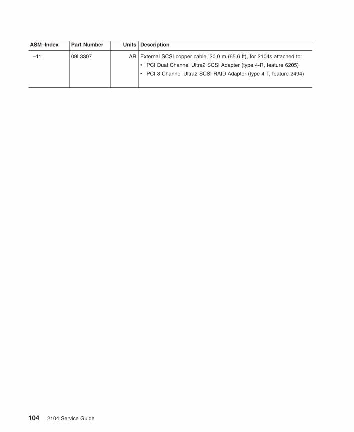
ASM–Index Part Number Units Description
–11 09L3307 AR External SCSI copper cable, 20.0 m (65.6 ft), for 2104s attached to:
v PCI Dual Channel Ultra2 SCSI Adapter (type 4-R, feature 6205)
v PCI 3-Channel Ultra2 SCSI RAID Adapter (type 4-T, feature 2494)
104 2104 Service Guide
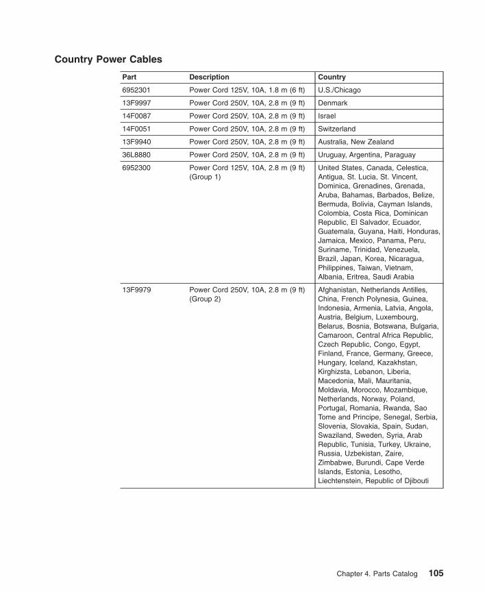
Country Power Cables
Part Description Country
6952301 Power Cord 125V, 10A, 1.8 m (6 ft) U.S./Chicago
13F9997 Power Cord 250V, 10A, 2.8 m (9 ft) Denmark
14F0087 Power Cord 250V, 10A, 2.8 m (9 ft) Israel
14F0051 Power Cord 250V, 10A, 2.8 m (9 ft) Switzerland
13F9940 Power Cord 250V, 10A, 2.8 m (9 ft) Australia, New Zealand
36L8880 Power Cord 250V, 10A, 2.8 m (9 ft) Uruguay, Argentina, Paraguay
6952300 Power Cord 125V, 10A, 2.8 m (9 ft)(Group 1)
United States, Canada, Celestica,Antigua, St. Lucia, St. Vincent,Dominica, Grenadines, Grenada,Aruba, Bahamas, Barbados, Belize,Bermuda, Bolivia, Cayman Islands,Colombia, Costa Rica, DominicanRepublic, El Salvador, Ecuador,Guatemala, Guyana, Haiti, Honduras,Jamaica, Mexico, Panama, Peru,Suriname, Trinidad, Venezuela,Brazil, Japan, Korea, Nicaragua,Philippines, Taiwan, Vietnam,Albania, Eritrea, Saudi Arabia
13F9979 Power Cord 250V, 10A, 2.8 m (9 ft)(Group 2)
Afghanistan, Netherlands Antilles,China, French Polynesia, Guinea,Indonesia, Armenia, Latvia, Angola,Austria, Belgium, Luxembourg,Belarus, Bosnia, Botswana, Bulgaria,Camaroon, Central Africa Republic,Czech Republic, Congo, Egypt,Finland, France, Germany, Greece,Hungary, Iceland, Kazakhstan,Kirghizsta, Lebanon, Liberia,Macedonia, Mali, Mauritania,Moldavia, Morocco, Mozambique,Netherlands, Norway, Poland,Portugal, Romania, Rwanda, SaoTome and Principe, Senegal, Serbia,Slovenia, Slovakia, Spain, Sudan,Swaziland, Sweden, Syria, ArabRepublic, Tunisia, Turkey, Ukraine,Russia, Uzbekistan, Zaire,Zimbabwe, Burundi, Cape VerdeIslands, Estonia, Lesotho,Liechtenstein, Republic of Djibouti
Chapter 4. Parts Catalog 105
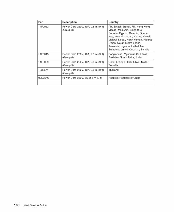
Part Description Country
14F0033 Power Cord 250V, 10A, 2.8 m (9 ft)(Group 3)
Abu Dhabi, Brunei, Fiji, Hong Kong,Macao, Malaysia, Singapore,Bahrain, Cyprus, Gambia, Ghana,Iraq, Ireland, Jordan, Kenya, Kuwait,Malawi, Nepal, North Yemen, Nigeria,Oman, Qatar, Sierra Leone,Tanzania, Uganda, United ArabEmirates, United Kingdom, Zambia.
14F0015 Power Cord 250V, 10A, 2.8 m (9 ft)(Group 4)
Bangladesh, Myanmar, Sri Lanka,Pakistan, South Africa, India
14F0069 Power Cord 250V, 10A, 2.8 m (9 ft)(Group 5)
Chile, Ethiopia, Italy, Libya, Malta,Somalia.
1838574 Power Cord 250V, 10A, 2.8 m (9 ft)(Group 6)
Thailand
02K0546 Power Cord 250V, 6A, 2.8 m (9 ft) People’s Republic of China
106 2104 Service Guide
Appendix A. Additional Information for RISC Systems
Related Publications . . . . . . . . . . . . . . . . . . . . . 107Web Support Page . . . . . . . . . . . . . . . . . . . . . . 107SCSI Adapters . . . . . . . . . . . . . . . . . . . . . . . 108Location Code Format . . . . . . . . . . . . . . . . . . . . . 109System Service Aids . . . . . . . . . . . . . . . . . . . . . 110
Format Media . . . . . . . . . . . . . . . . . . . . . . . 110Certify Media . . . . . . . . . . . . . . . . . . . . . . . 110SCSI Device Identification and Removal . . . . . . . . . . . . . . 111Download Microcode to a Disk Drive or to an SCSI Interface Card . . . . . 112
Downloading to Disk Drives . . . . . . . . . . . . . . . . . 112Downloading to SCSI Interface Cards . . . . . . . . . . . . . . 112
Software and Microcode Errors . . . . . . . . . . . . . . . . . . 113Diagnostics Information . . . . . . . . . . . . . . . . . . . . 113
Concurrent Diagnostics. . . . . . . . . . . . . . . . . . . . 113Nonconcurrent Diagnostics . . . . . . . . . . . . . . . . . . 113Problems Corrected . . . . . . . . . . . . . . . . . . . . . 113
Collecting Errors . . . . . . . . . . . . . . . . . . . . . . . 114Configuring a Disk Drive Module to the Using System . . . . . . . . . . 114Configuring a 2104 to the Using System . . . . . . . . . . . . . . . 115Unconfiguring a 2104 from the Using System . . . . . . . . . . . . . 115
This appendix provides information that is specific to 2104s that are attached to RISCsystems.
Related Publicationsv Diagnostic Information for Micro Channel Bus Systems, SA23-2765
v Diagnostic Information for Multiple Bus Systems, SA38-0509
v Site and Hardware Planning Information, SA38-0508
v Adapters, Devices, and Cable Information for Micro Channel Bus Systems,SA23-2764
v Adapters, Devices, and Cable Information for Multiple Bus Systems, SA38-0516
Web Support Page
You can find the web support page at:
http://www.rs6000.ibm.com/support/
107

SCSI Adapters
The 2104 can be attached to any of these types of SCSI adapter:
v PCI Dual Channel Ultra2 SCSI Adapter (type 4-R, feature 6205)
v PCI 3-Channel Ultra2 SCSI RAID Adapter (type 4-T, feature 2494)
v PCI Single-Ended Ultra SCSI Adapter (type 4-K, feature 6206)
v PCI SCSI-2 Single_Ended Fast/Wide Adapter (type 4_A, feature 6208)
v PCI SCSI-2 Fast/Wide RAID Adapter (type 4-H, feature 2493)
v SCSI-2 Fast/Wide Adapter/A (type 4-7, feature 2415)
108 2104 Service Guide
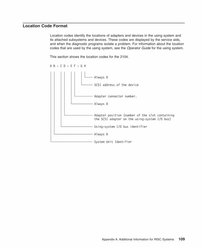
Location Code Format
Location codes identify the locations of adapters and devices in the using system andits attached subsystems and devices. These codes are displayed by the service aids,and when the diagnostic programs isolate a problem. For information about the locationcodes that are used by the using system, see the Operator Guide for the using system.
This section shows the location codes for the 2104.
A B - C D - E F - G H
│ │ │ │ │ │ │ ││ │ │ │ │ │ │ └──── Always 0│ │ │ │ │ │ ││ │ │ │ │ │ └────── SCSI address of the device│ │ │ │ │ ││ │ │ │ │ ││ │ │ │ │ └────────── Adapter connector number.│ │ │ │ ││ │ │ │ └──────────── Always 0│ │ │ ││ │ │ ││ │ │ └──────────────── Adapter position (number of the slot containing│ │ │ the SCSI adapter on the using-system I/O bus)│ │ ││ │ └────────────────── Using-system I/O bus identifier│ ││ └────────────────────── Always 0│└──────────────────────── System Unit Identifier
Appendix A. Additional Information for RISC Systems 109
System Service Aids
Service aids are available on the using system to help you service the 2104. Thissection briefly describes some of those aids, and tells how to use them. More detailsare given in the service information for the using system.
The service aids that are described here are:
v Format Media
v Certify Media
v SCSI Device Identification and Removal
v Download Microcode
Format Media
Attention: The Format Media service aid destroys all data on the disk.
To run this service aid:
1. Install the disk drive module (if not already installed) into the 2104.
2. Ensure that power is present in the 2104.
3. Go to the using system, select Diagnostic Operating Instructions, and follow theinstructions to select the Function Selection menu.
4. Select Task Selection.
5. Select Format Media, and follow the instructions given.
Note: You cannot start the Format Media service aid if I/O operations are runningon the disk drive.
Attention: Formatting the wrong disk drive might destroy valuable data.
If you are not sure about the location code for the disk-drive module that you wantto format, see “Location Code Format” on page 109 for an explanation of the codes.
The Format Media service aid can take up to 15 minutes to run. If it completessuccessfully, run the Certify Media service aid before the disk drive module is used.
Certify Media
The Certify Media service aid checks the disk for defective sectors. Before runningCertify Media, ensure that the diagnostics can run in System Verification mode withouterrors to the disk drive module.
To run this service aid:
1. Go to the using system, select Diagnostic Operating Instructions, and follow theinstructions to select the Function Selection menu.
2. Select Task Selection.
110 2104 Service Guide
3. Select Certify Media, and follow the instructions given.
The Certify service aid takes approximately 10 minutes to run.
SCSI Device Identification and Removal
To run this service aid:
1. Go to the using system, select Diagnostic Operating Instructions, and follow theinstructions to select the Function Selection menu.
2. Select Task Selection.
3. Select Identify and Remove Resource.
4. Select the device (enclosure or disk drive) from the displayed list.
5. Select the slot from the displayed list.
6. A menu is displayed. From this menu, you can choose to:
v Set a disk drive module to Identify. The Check light of the selected disk drivemodule flashes so that you can physically identify that module. The Identifyfunction does not affect the operation of the disk drive module.
v Set a disk drive module to Remove. The Check light of the selected disk drivemodule comes on and remains on continuously so that you can physically identifythe module that you are going to remove. The light goes off when the disk drivemodule is removed. The Remove function does not affect the operation of thedisk drive module until that module is removed.
v Set a disk drive slot to Insert. The Check light at the back of the slot (on thebackplane) comes on and remains on continuously so that you can physicallyidentify the slot into which you are going to install a disk drive module.
v Set a disk drive module or slot to Normal. The Check light of the disk drivemodule, or slot, goes off.
Appendix A. Additional Information for RISC Systems 111
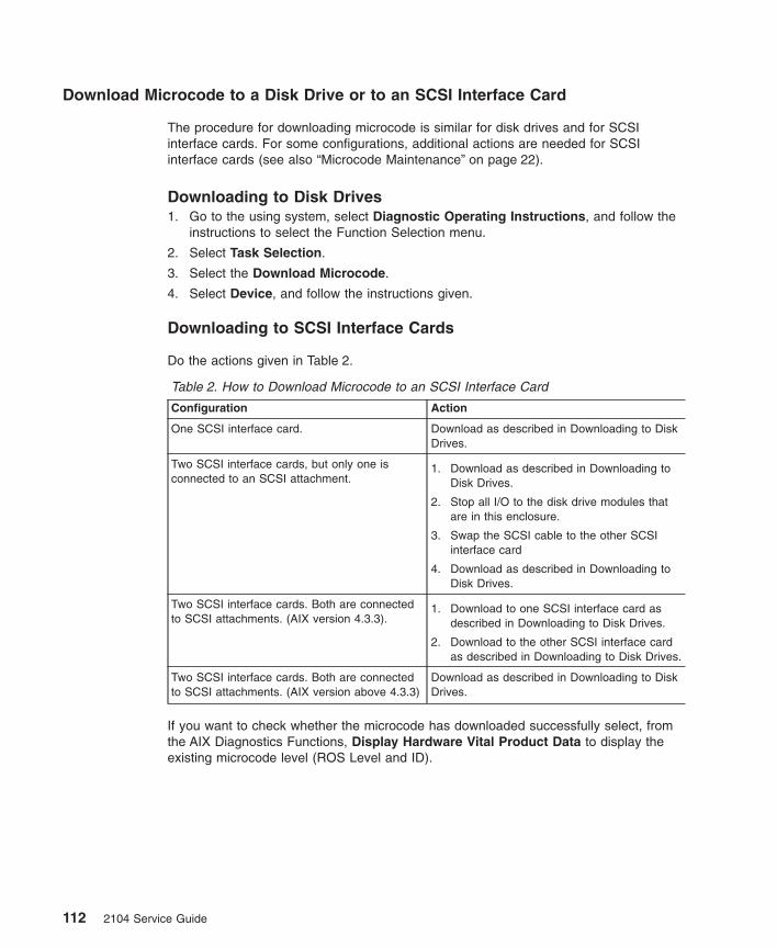
Download Microcode to a Disk Drive or to an SCSI Interface Card
The procedure for downloading microcode is similar for disk drives and for SCSIinterface cards. For some configurations, additional actions are needed for SCSIinterface cards (see also “Microcode Maintenance” on page 22).
Downloading to Disk Drives1. Go to the using system, select Diagnostic Operating Instructions, and follow the
instructions to select the Function Selection menu.
2. Select Task Selection.
3. Select the Download Microcode.
4. Select Device, and follow the instructions given.
Downloading to SCSI Interface Cards
Do the actions given in Table 2.
Table 2. How to Download Microcode to an SCSI Interface Card
Configuration Action
One SCSI interface card. Download as described in Downloading to DiskDrives.
Two SCSI interface cards, but only one isconnected to an SCSI attachment.
1. Download as described in Downloading toDisk Drives.
2. Stop all I/O to the disk drive modules thatare in this enclosure.
3. Swap the SCSI cable to the other SCSIinterface card
4. Download as described in Downloading toDisk Drives.
Two SCSI interface cards. Both are connectedto SCSI attachments. (AIX version 4.3.3).
1. Download to one SCSI interface card asdescribed in Downloading to Disk Drives.
2. Download to the other SCSI interface cardas described in Downloading to Disk Drives.
Two SCSI interface cards. Both are connectedto SCSI attachments. (AIX version above 4.3.3)
Download as described in Downloading to DiskDrives.
If you want to check whether the microcode has downloaded successfully select, fromthe AIX Diagnostics Functions, Display Hardware Vital Product Data to display theexisting microcode level (ROS Level and ID).
112 2104 Service Guide
Software and Microcode Errors
Some failures might be caused by software errors or by microcode errors. If you thinkyou have a software or microcode error:
1. Ensure that your system software, adapter microcode, disk drive microcode, andenclosure microcode are all at the latest levels. Information about the latest levels ofsoftware and microcode is given on the web support page (see “Web Support Page”on page 107).
2. Make a note of all failure indicators: for example, the contents of error logs, orphysical symptoms.
3. For AIX Versions 4.2 and above, run the snap -g command to collect systemconfiguration data, and to dump data.
For AIX versions below 4.2, go to the using-system service aids and select DisplayVital Product Data to display the VPD of the failing system. Make a note of theVPD for all the SCSI adapters and disk drives.
4. Report the problem to your support center. The center can tell you whether youhave a known problem, and can, if necessary, provide you with a correction for thesoftware or microcode.
Diagnostics Information
Note: If you were sent here from other instructions, return to those instructions whenyou have finished running the diagnostics.
Concurrent Diagnostics
When the instructions tell you to run concurrent diagnostics, run diagnostics (notAdvanced Diagnostics) in System Verification mode (see the using-system Installationand Service Guide).
Nonconcurrent Diagnostics
When the instructions tell you to run nonconcurrent diagnostics, run AdvancedDiagnostics in System Verification mode (see the using-system Installation and ServiceGuide).
Problems Corrected
Run Advanced Diagnostics in System Verification mode only to the device that youhave just repaired. You can then enter information to prevent the generation of anotherSRN for the problem that you have just solved. If you do not enter that information, theerrors that were previously logged for your problem might generate another SRN.
Appendix A. Additional Information for RISC Systems 113
Collecting Errors
To collect enclosure errors, add this cron job SES Healthcheck to the system cron table.
Note: You must have root permissions to complete this procedure.
Edit the system crons with the crontab -e command. At the bottom of the file, enter:
15 * * * * /usr/lpp/diagnostics/bin/run_ses_healthcheck 1> /dev/null 2> /dev/null
For further information about the crontab command, see the web page at:
http://www.rs6000.ibm.com/doc_link/en_US/a_doc_lib/cmds/aixcmds1/crontab.htm#A1599114e
This cron runs at 15 minutes after each hour, and sends mail to the “root user” withdetails of any errors that are present in the enclosure. It also presents a consolemessage indicating which enclosure has a problem.
The cron requires a script. To create this script, generate a file namedrun_ses_healthcheck in directory /usr/lpp/diagnostics/bin. The contents of the file mustbe:
#!/bin/ksh#Name: run_ses_healthcheck#Location: /usr/lpp/diagnostics/bin#Function: SCSI SES hourly healthcheck
/usr/sbin/lsdev -Cc container -t ses -s scsi -F name -S available |/usr/bin/xargs -n1 -i /bin/nice --10 /usr/lpp/diagnostics/bin/diagela -t {}
Note: Although, because of page width, the final line of the contents is shown heresplit between two lines, you must enter it all on one line.
Give the following command so that the script can be run:
chmod 544 /usr/lpp/diagnostics/bin/run_ses_healthcheck
Configuring a Disk Drive Module to the Using System
If you have just installed a new disk drive module, and want to change the hdisknumber, do the following:
1. Remove the new hdisk number by giving the command:
rmdev -l [hdisknumber] -d
where [hdisknumber] is the hdisk number that you want to remove (for example,hdisk12).
2. Remove the definition of the original hdisk by giving the command:
rmdev -l [hdisknumber] -d
114 2104 Service Guide
where [hdisknumber] is the hdisk number of the original disk drive module (forexample, hdisk7).
3. Run the cfgmgr command.
Configuring a 2104 to the Using System
Use the cfgmgr command to configure or reconfigure a 2104 to the using system.
Unconfiguring a 2104 from the Using System
To remove a 2104 from the using system, give the following command:
rmdev -l [enclosurenumber] -d
where [enclosurenumber] is the enclosure device that was generated by the cfgmgrcommand (for example, [ses0], [ses1], [ses2]).
Appendix A. Additional Information for RISC Systems 115

116 2104 Service Guide
Appendix B. Translated Safety Notices
This appendix contains the danger and caution notices that are used in the variousbooks related to the Expandable Storage Plus: 2104 Models DL1 and TL1. The noticesare shown in English and in various other languages.
Danger notice A danger notice calls attention to a situation that is potentially lethal orextremely hazardous to people.
Caution notice A caution notice calls attention to a situation that is potentiallyhazardous to people because of some existing condition.
Always use safe working procedures whenever you work on machines. Use your ownjudgment to identify safety conditions that these notices do not describe.
Danger Notices
DANGER
In the following step you are going to remove the power cables. These cablesare live if the rack power distribution unit or battery-backup unit is stillswitched on.
DANGER
Do not try to open the covers of the fan-and-power-supply assembly.
117
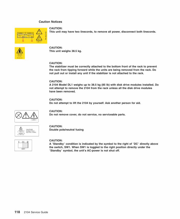
Caution Notices
CAUTION:This unit may have two linecords, to remove all power, disconnect both linecords.
CAUTION:This unit weighs 38.5 kg.
CAUTION:The stabilizer must be correctly attached to the bottom front of the rack to preventthe rack from tipping forward while the units are being removed from the rack. Donot pull out or install any unit if the stabilizer is not attached to the rack.
CAUTION:A 2104 Model DL1 weighs up to 38.5 kg (85 lb) with disk drive modules installed. Donot attempt to remove the 2104 from the rack unless all the disk drive moduleshave been removed.
CAUTION:Do not attempt to lift the 2104 by yourself. Ask another person for aid.
CAUTION:Do not remove cover, do not service, no serviceable parts.
CAUTION:Double pole/neutral fusing
CAUTION:A ″Standby″ condition is indicated by the symbol to the right of ″DC″ directly abovethe switch, SW1. When SW1 is toggled to the right position directly under the″Standby″ symbol, the unit’s AC-power is not shut off.
118 2104 Service Guide
Cette annexe contient la traduction des consignes de type Danger etAttention figurant dans les diff rents manuels concernant ExpandableStorage Plus: 2104 Models DL1 and TL1.
é
Consignes de type Danger Les consignes de s curit de type Dangerindiquent la pr sence d'un risque de blessuresgraves, voire mortelles.
é éé
Consignes de type Attention Les consignes de s curit de type Attentionindiquent la pr sence d'un risque de blessuresl g res.
é éé
é è
Consignes Danger
Dans l’ tape qui suit, vous allez devoir d brancher les cordonsd'alimentation. Ces cordons sont toujours aliment s si le cordond'alimentation de l'armoire ou la batterie de secours sont enfonction.
é éé
DANGER
DANGER
N'essayez pas d'ouvrir le bloc ventilateur-alimentation.
Français
Traduction des consignes de s curité é
Respectez toujours les consignes de s curit lorsque vous travaillezsur des machines. Mettez vous m me en place les conditions des curit n cessaires dans les cas non pr vus par ces consignes.
é éê
é é é é
Appendix B. Translated Safety Notices 119
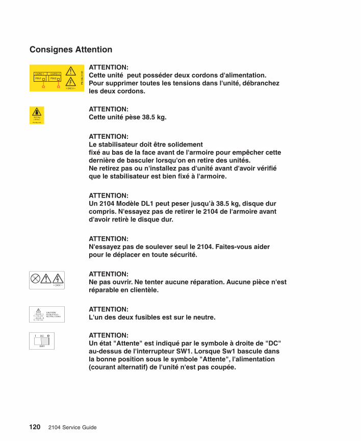
Consignes Attention
ATTENTION:Le stabilisateur doit tre solidementfix au bas de la face avant de l'armoire pour emp cher cettederni re de basculer lorsqu'on en retire des unit s.Ne retirez pas ou n'installez pas d'unit avant d'avoir v rifique le stabilisateur est bien fix l'armoire.
êé ê
è éé é é
é à
ATTENTION:Cette unit p se 38.5 kg.é è
ATTENTION:Un 2104 Mod le DL1 peut peser jusqu’ 38.5 kg, disque durcompris. N'essayez pas de retirer le 2104 de l'armoire avantd'avoir retir le disque dur.
è à
è
ATTENTION:N'essayez pas de soulever seul le 2104. Faites-vous aiderpour le d placer en toute s curit .é é é
ATTENTION:Ne pas ouvrir. Ne tenter aucune r paration. Aucune pi ce n'estr parable en client le.
é èé è
ATTENTION:L'un des deux fusibles est sur le neutre.
ATTENTION:Un tat "Attente" est indiqu par le symbole droite de "DC"au-dessus de l'interrupteur SW1. Lorsque Sw1 bascule dansla bonne position sous le symbole "Attente", l'alimentation(courant alternatif) de l'unit n'est pas coup e.
é é à
é é
ATTENTION:Cette unit peut poss der deux cordons d'alimentation.Pour supprimer toutes les tensions dans l'unit , d branchezles deux cordons.
é éé é
DC
SW1
CAUTION:
DOUBLE POLE /
NEUTRAL FUSING
F2 = T10A / 250V
F1 = T10A / 250VL
N
120 2104 Service Guide
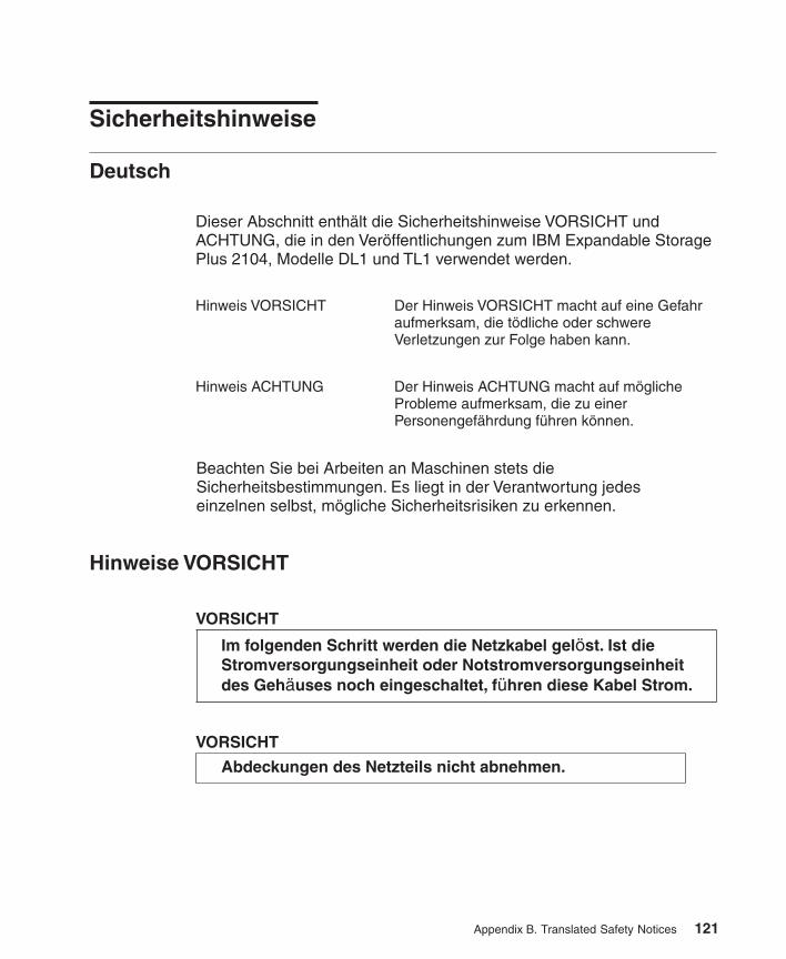
Dieser Abschnitt enth lt die Sicherheitshinweise VORSICHT undACHTUNG, die in den Ver ffentlichungen zum IBM Expandable StoragePlus 2104, Modelle DL1 und TL1 verwendet werden.
äö
Hinweis VORSICHT Der Hinweis VORSICHT macht auf eine Gefahraufmerksam, die t dliche oder schwereVerletzungen zur Folge haben kann.
ö
Hinweis ACHTUNG Der Hinweis ACHTUNG macht auf m glicheProbleme aufmerksam, die zu einerPersonengef hrdung f hren k nnen.
ö
ä ü ö
Hinweise VORSICHT
Im folgenden Schritt werden die Netzkabel gel st. Ist dieStromversorgungseinheit oder Notstromversorgungseinheitdes Geh uses noch eingeschaltet, f hren diese Kabel Strom.
ö
ä ü
VORSICHT
VORSICHT
Abdeckungen des Netzteils nicht abnehmen.
Deutsch
Sicherheitshinweise
Beachten Sie bei Arbeiten an Maschinen stets dieSicherheitsbestimmungen. Es liegt in der Verantwortung jedeseinzelnen selbst, m gliche Sicherheitsrisiken zu erkennen.ö
Appendix B. Translated Safety Notices 121
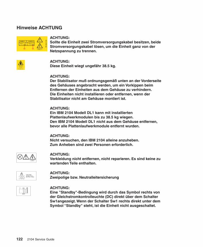
Hinweise ACHTUNG
ACHTUNG:Der Stabilisator muß ordnungsgemäß unten an der Vorderseitedes Gehäuses angebracht werden, um ein Vorkippen beimEntfernen der Einheiten aus dem Gehäuse zu verhindern.Die Einheiten nicht installieren oder entfernen, wenn derStabilisator nicht am Gehäuse montiert ist.
ACHTUNG:Diese Einheit wiegt ungef hr 38.5 kg.ä
ACHTUNG:Ein IBM 2104 Modell DL1 kann mit installiertenPlattenlaufwerkmodulen bis zu 38.5 kg wiegen.Den IBM 2104 Modell DL1 nicht aus dem Gehäuse entfernen,bevor alle Plattenlaufwerkmodule entfernt wurden.
ACHTUNG:Nicht versuchen, den IBM 2104 alleine anzuheben.Zum Anheben sind zwei Personen erforderlich.
ACHTUNG:Verkleidung nicht entfernen, nicht reparieren. Es sind keine zuwartenden Teile enthalten.
ACHTUNG:Zweipolige bzw. Neutralleitersicherung
ACHTUNG:Eine "Standby"-Bedingung wird durch das Symbol rechts vonder Gleichstromkontrolleuchte (DC) direkt über dem SchalterSw1angezeigt. Wenn der Schalter Sw1 rechts direkt unter demSymbol “Standby" steht, ist die Einheit nicht ausgeschaltet.
ACHTUNG:Sollte die Einheit zwei Stromversorgungskabel besitzen, beideStromversorgungskabel l sen, um die Einheit ganz von derNetzspannung zu trennen.
ö
DC
SW1
CAUTION:
DOUBLE POLE /
NEUTRAL FUSING
F2 = T10A / 250V
F1 = T10A / 250VL
N
122 2104 Service Guide
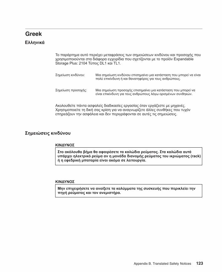
Greek
Appendix B. Translated Safety Notices 123
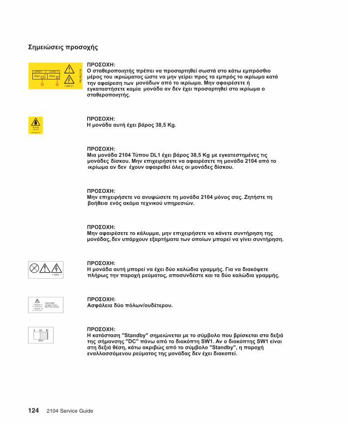
DC
SW1
CAUTION:
DOUBLE POLE /
NEUTRAL FUSING
F2 = T10A / 250V
F1 = T10A / 250VL
N
124 2104 Service Guide
Appendix B. Translated Safety Notices 125
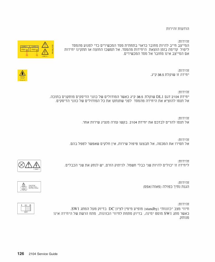
126 2104 Service Guide
Appendix B. Translated Safety Notices 127
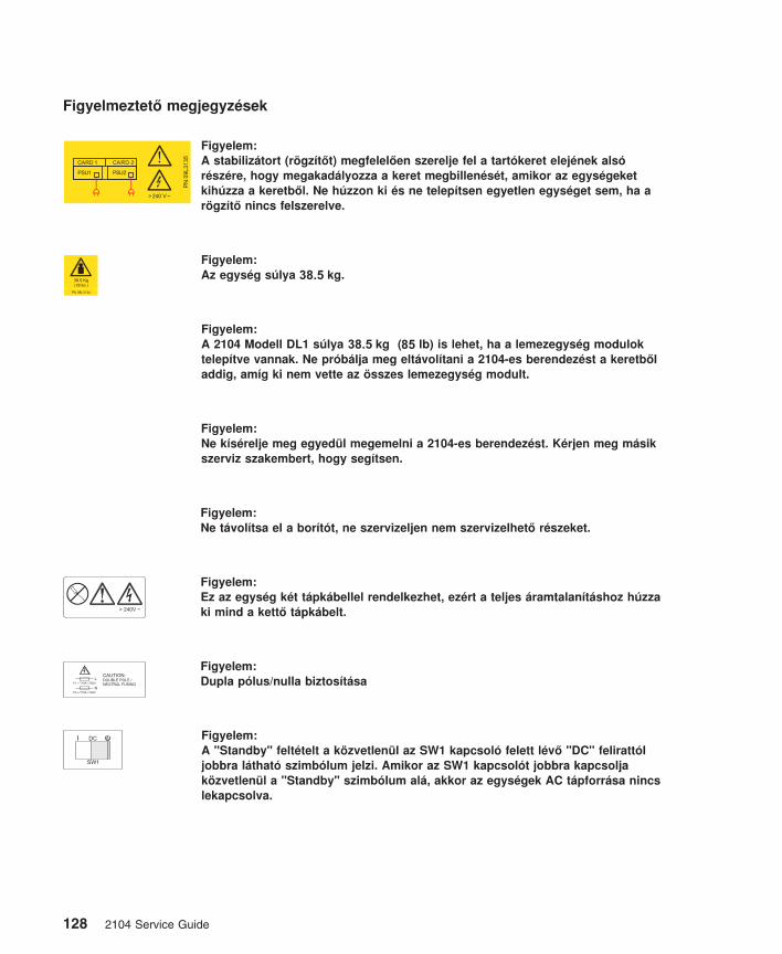
DC
SW1
CAUTION:
DOUBLE POLE /
NEUTRAL FUSING
F2 = T10A / 250V
F1 = T10A / 250VL
N
38.5
38.5 85
128 2104 Service Guide
Questo opuscolo contiene la traduzione degli avvisi di pericolo e diattenzione presenti nei manuali relativi all'Expandable Storage Plus:2104 Modelli DL1 e Tl1.
Avviso di pericolo Un avviso di pericolo richiama l'attenzione su unasituazione potenzialmente mortale oppureestremamente pericolosa per le persone.
Avviso di attenzione Un avviso di attenzione richiama l'attenzione su unasituazione che, in presenza di alcune condizioni,potenzialmente pericolosa per le persone.
è
Avvisi di pericolo
Al prossimo passo, sar necessario rimuovere i cavi dialimentazione. Se l'unit di distribuzione dell'energia nel rack el'unit batteria di riserva sono ancora accese, tali cavi sono intensione.
àà
à
PERICOLO
PERICOLO
Non tentare di aprire i coperchi dell'assiemeventilatore-alimentatore.
Italiano
Informazioni relativi alla sicurezza
Rispettare sempre le norme di sicurezza quando si utilizzano lemacchine. Valutare con attenzione eventuali condizioni di rischio che nonsono descritte in questi avvisi.
Appendix B. Translated Safety Notices 129
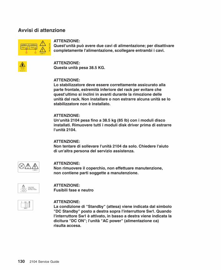
Avvisi di attenzione
ATTENZIONE:Lo stabilizzatore deve essere correttamente assicurato allaparte frontale, estremit inferiore del rack per evitare chequest'ultimo si inclini in avanti durante la rimozione delleunit dal rack. Non installare o non estrarre alcuna unit se lostabilizzatore non installato.
à
à àè
ATTENZIONE:Questa unit pesa 38.5 KG.à
ATTENZIONE:Un'unit 2104 pesa fino a 38.5 kg (85 lb) con i moduli discoinstallati. Rimuovere tutti i moduli disk driver prima di estrarrel'unit 2104.
à
à
ATTENZIONE:Non tentare di sollevare l'unit 2104 da solo. Chiedere l'aiutodi un'altra persona del servizio assistenza.
à
ATTENZIONE:Non rimuovere il coperchio, non effettuare manutenzione,non contiene parti soggette a manutenzione.
ATTENZIONE:Fusibili fase e neutro
ATTENZIONE:La condizione di "Standby" (attesa) viene indicata dal simbolo"DC Standby" posto a destra sopra l'interruttore Sw1. Quandol'interruttore Sw1 attivato, in basso a destra viene indicata ladicitura "DC ON"; l'unit "AC power" (alimentazione ca)risulta accesa.
èà
ATTENZIONE:Quest'unit pu avere due cavi di alimentazione; per disattivarecompletamente l'alimentazione, scollegare entrambi i cavi.
à ò
DC
SW1
CAUTION:
DOUBLE POLE /
NEUTRAL FUSING
F2 = T10A / 250V
F1 = T10A / 250VL
N
130 2104 Service Guide
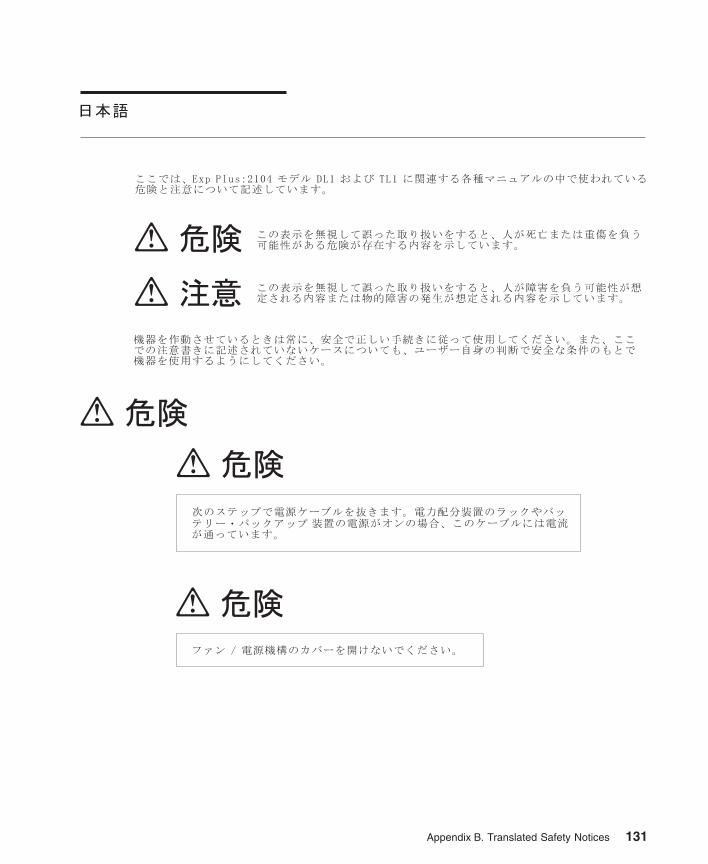
Appendix B. Translated Safety Notices 131
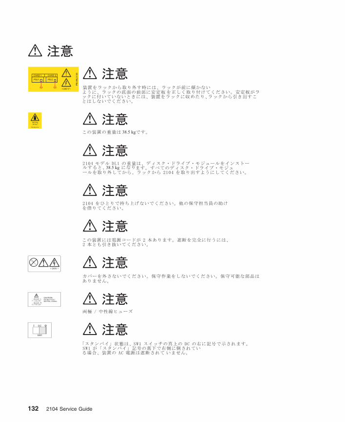
132 2104 Service Guide
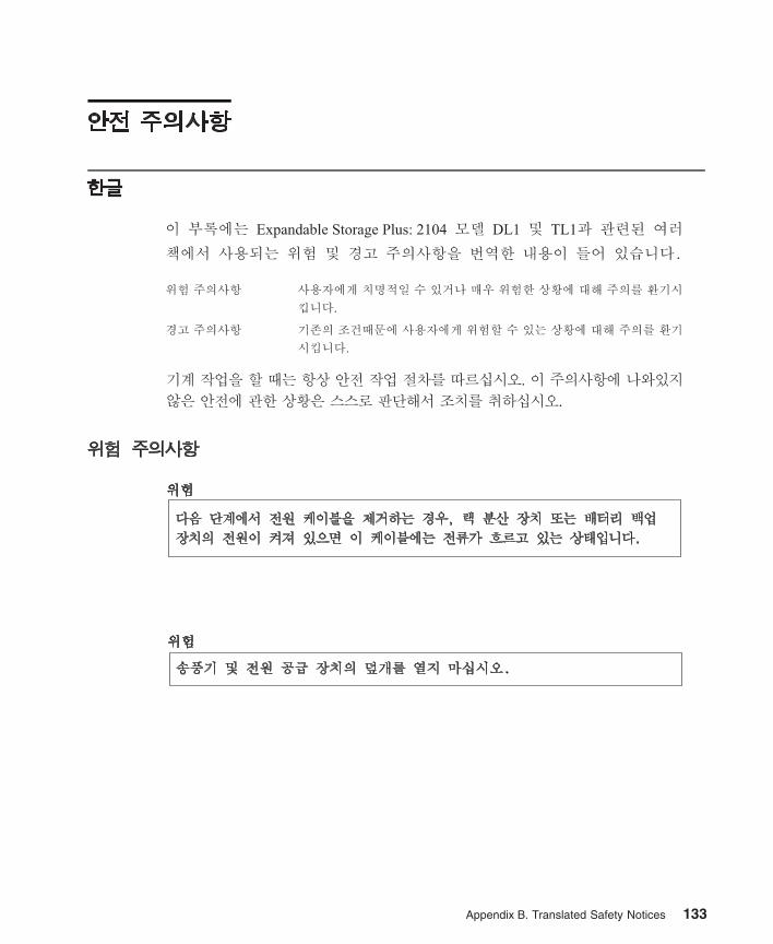
Appendix B. Translated Safety Notices 133
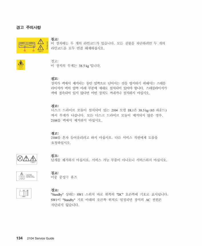
DC
SW1
CAUTION:
DOUBLE POLE /
NEUTRAL FUSING
F2 = T10A / 250V
F1 = T10A / 250VL
N
38.5
134 2104 Service Guide
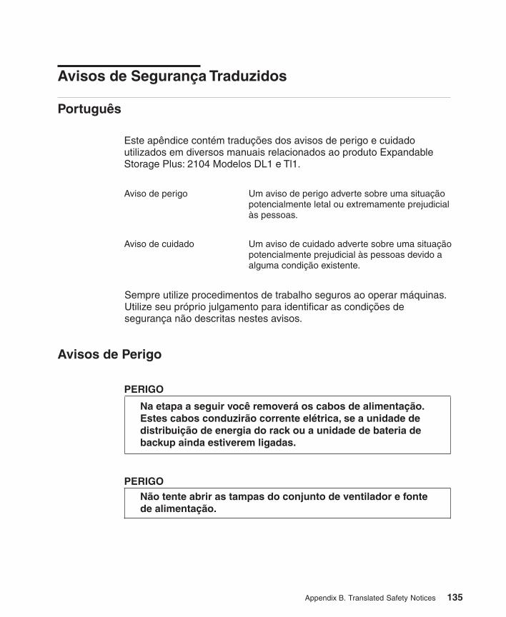
Este apêndice contém traduções dos avisos de perigo e cuidadoutilizados em diversos manuais relacionados ao produto ExpandableStorage Plus: 2104 Modelos DL1 e Tl1.
Aviso de perigo Um aviso de perigo adverte sobre uma situaçãopotencialmente letal ou extremamente prejudicialàs pessoas.
Aviso de cuidado Um aviso de cuidado adverte sobre uma situaçãopotencialmente prejudicial às pessoas devido aalguma condição existente.
Avisos de Perigo
Na etapa a seguir você removerá os cabos de alimentação.Estes cabos conduzirão corrente elétrica, se a unidade dedistribuição de energia do rack ou a unidade de bateria debackup ainda estiverem ligadas.
PERIGO
PERIGO
Não tente abrir as tampas do conjunto de ventilador e fontede alimentação.
Português
Avisos de Segurança Traduzidos
Sempre utilize procedimentos de trabalho seguros ao operar máquinas.Utilize seu próprio julgamento para identificar as condições desegurança não descritas nestes avisos.
Appendix B. Translated Safety Notices 135
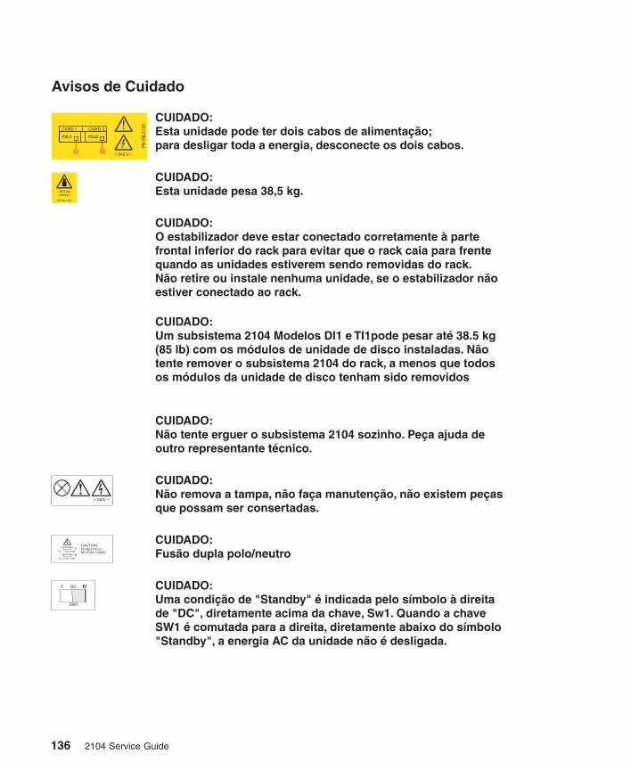
Avisos de Cuidado
CUIDADO:O estabilizador deve estar conectado corretamente à partefrontal inferior do rack para evitar que o rack caia para frentequando as unidades estiverem sendo removidas do rack.Não retire ou instale nenhuma unidade, se o estabilizador nãoestiver conectado ao rack.
CUIDADO:Esta unidade pesa 38,5 kg.
CUIDADO:Um subsistema 2104 Modelos Dl1 e TI1pode pesar até 38.5 kg(85 lb) com os módulos de unidade de disco instaladas. Nãotente remover o subsistema 2104 do rack, a menos que todosos módulos da unidade de disco tenham sido removidos
CUIDADO:Não tente erguer o subsistema 2104 sozinho. Peça ajuda deoutro representante técnico.
CUIDADO:Não remova a tampa, não faça manutenção, não existem peçasque possam ser consertadas.
CUIDADO:Fusão dupla polo/neutro
CUIDADO:Uma condição de "Standby" é indicada pelo símbolo à direitade "DC", diretamente acima da chave, Sw1. Quando a chaveSW1 é comutada para a direita, diretamente abaixo do símbolo"Standby", a energia AC da unidade não é desligada.
CUIDADO:Esta unidade pode ter dois cabos de alimentação;para desligar toda a energia, desconecte os dois cabos.
DC
SW1
CAUTION:
DOUBLE POLE /
NEUTRAL FUSING
F2 = T10A / 250V
F1 = T10A / 250VL
N
136 2104 Service Guide
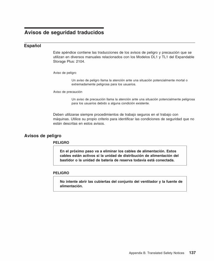
Appendix B. Translated Safety Notices 137
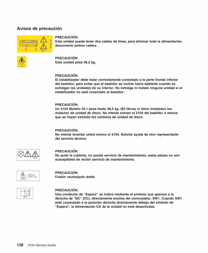
DC
SW1
CAUTION:
DOUBLE POLE /
NEUTRAL FUSING
F2 = T10A / 250V
F1 = T10A / 250VL
N
138 2104 Service Guide
Index
Numerics2104 serial number location 19
Aac/dc voltage requirements 20AC PWR light 6acclimation of disk drives 21Activity light, disk drive module 12adapters 108air temperature 20altitude 21ANSI SCSI enclosure services (SES) 25Attention notices
concurrent maintenancefan-and-power-supply assemblies 71fan assembly 74
do not switch off the using system 66Format Media service aid 110formatting disk drives 110fragility of disk drive modules 37, 61, 66grounding of 2104 29grounding of the 2104 27removal of SCSI interface card assembly 76
Bbooks, related
for 2104 xiiiRISC systems 107
Ccable configurations 23catalog of parts 99Caution notices
rack stabilizer 84, 91weight of 2104 Model DL1 84weight of the 2104 91
Certify Media service aid 110changing disk drive numbers
RISC systems 114Check light, disk drive module 12Check light, Subsystem 5checking the grounding 27
2104 Model DL1 272104 Model TL1 29
checklist, inspection 26CHK light 6CHK light (fan) 7collecting errors
RS/6000 114concurrent diagnostics
RISC systems 113concurrent maintenance 53
configurations 3configuring a 2104 to the using system
RISC systems 115configuring a disk drive module to the using system
RISC systems 114connectors
2104 Model DL1 162104 Model TL1 17mainline-power 18
country power cables 105
DDanger notices
fan-and-power-supply unit 73power cables 57
dc/ac voltage requirements 20DC On/Standby switch 6DC PWR light 6definition of FRU names used in SRN table 33diagnostic aids
disk drive module POSTs (power-on self-tests) 31SCSI interface card POSTs (power-on self-tests) 31SRNs (service request numbers) 32
diagnostics informationconcurrent diagnostics
RISC systems 113nonconcurrent diagnostics
RISC systems 113problems corrected
RISC systems 113dimensions and weight
2104 Model DL1 202104 Model TL1 20
disk drive module serial number location 19disk drive modules
2104 Model DL1location 14
2104 Model TL1location 15
acclimation 21Activity light 12Check light 12installing 66numbering
2104 Model DL1 142104 Model TL1 15
POSTs (power-on self-tests) 31removing 61
Download Microcode to a Disk Drive or an SCSIInterface Card 112
dummy disk drive modulesinstalling 66
139
dummy disk drive modules (continued)removing 61
Eelectrical hazards 26electrical requirements 20Enable Enclosure Services switch 10Enclosure ID switch 10enclosure services 25
ANSI SCSI enclosure services (SES) 25Enclosure Services Selector switch 10environmental characteristics 20error logging 3
Ffan-and-power-supply assemblies
AC PWR light 6CHK light 6DC On/Standby switch 6DC PWR light 6location
2104 Model DL1 142104 Model TL1 15
fan assemblyCHK light 7location
2104 Model DL1 14removal and replacement 74
FAULT light 6Format Media service aid 110frame assembly
removal and replacement 83frequency (voltage) 20FRU names used in SRN table 33
Gglossary of FRU names used in SRN table 33grounding check 27
2104 Model DL1 272104 Model TL1 29
Hhazards, safety 26heat output 21humidity 20
Iindicators
AC PWR light 6CHK light 6CHK light (fan) 7DC PWR light 6disk drive module Activity light 12disk drive module Check light 12FAULT light 6LVD/SE light 6RESET light 6
indicators (continued)Subsystem Check light 5Subsystem Power light 5TERM POWER light 6
inspection guide 26checklist 26
Llabels
2104 serial number2104 Model DL1 192104 Model TL1 19
disk drive module serial number 19product information
checking 26lights
AC PWR 6ACTIVE 6CHK 6CHK (fan) 7DC PWR 6disk drive module Activity 12disk drive module Check 12FAULT 6LVD/SE 6RESET 6Subsystem Check 5Subsystem Power 5TERM POWER 6
LVD/SE light 6
Mmainline-power connector 18maintenance analysis procedures (MAPs) 37manuals, related
for 2104 xiiifor RISC systems 107
mechanical hazards 26microcode and software errors
RISC systems 113microcode maintenance 22
Nnonconcurrent diagnostics
RISC systems 113numbering convention xiiinumbering of disk drive modules
2104 Model DL1 142104 Model TL1 15
Pparts catalog 99parts locations
2104 Model DL1disk drive module 14fan-and-power-supply assembly 14
140 2104 Service Guide
parts locations (continued)fan assembly 14SCSI interface card assembly 14switch card 14
2104 Model TL1disk drive module 15fan-and-power-supply assemblies 15SCSI interface card assembly 15switch card 15
serial-number label 19POSTs (power-on self-tests)
disk drive module 31SCSI interface card 31
power cables, country 105Power Control switch 9Power light, Subsystem 5power requirements 20power sequencing 21powering on and powering off
2104 Model DL1 572104 Model TL1 59
problem determinationPOSTs, disk drive module (power-on self-tests) 31POSTs, SCSI interface card (power-on self-tests) 31procedures 31SRNs (service request numbers) 32, 33
problems correctedRISC systems 113
product characteristics 20product-information label 26publications, related
for 2104 xiiiRISC systems 107
Rreference information 1related publications
for 2104 xiiiRISC systems 107
removal and replacement procedures 532104 91disk drive modules
installing 66removing 61
dummy disk drive modulesinstalling 66removing 61
fan assembly 74frame assembly 83front cover, 2104 Model TL1 54power
2104 Model DL1 572104 Model TL1 59
SCSI interface card assembly 76support rails 96
removal and replacement procedures 53 (continued)switch card assembly 80
RESET light 6
SSAF-TE 25safety hazards 26safety notices xi
definition of xifor installing, relocating, or servicing xitranslated 117
SCSI adapters 108SCSI addresses 22SCSI Device Identification and Removal service aid 111SCSI interface card assembly
2104 Model DL1location 14
2104 Model TL1location 15
description 3POSTs (power-on self-tests) 31removal and replacement 76
SCSI terminators 3serial number location
2104 Model DL1 192104 Model TL1 19disk drive module 19
service aidsCertify Media 110Download Microcode to a Disk Drive or an SCSI
Interface Card 112Format Media 110SCSI Device Identification and Removal 111
service functions 25service inspection guide 26
checklist 26services
SAF-TE 25slots, disk drive module
numbering2104 Model TL1 15
numbering (IDs)2104 Model DL1 14
software and microcode errorsRISC systems 113
specifications 20SRNs (service request numbers) 32Subsystem Check light 5Subsystem Power light 5support page URL
RISC systems 107support rails
removal and replacement procedures 96switch card assembly
removal and replacement 80switches 8
Index 141
switches
2104 orientation 11DC On/Standby 6Enable Enclosure Services 10Enclosure ID 10Power Control 9Select Enclosure Services 10
system service aids 110
Certify Media 110Download Microcode to a Disk Drive or an SCSI
Interface Card 112Format Media 110SCSI Device Identification and Removal 111
Ttemperature, air 20
TERM POWER light 6
terminators, SCSI 3
translated safety notices 117
Uunconfiguring a 2104 from the using system
RISC systems 115
URL for support page
RISC systems 107
Vvital product data 24
voltage and frequency 20
VPD (vital product data) 24
Wweb support page
RISC systems 107
weight and dimensions
2104 Model DL1 202104 Model TL1 20
142 2104 Service Guide

Part Number: 09L3327
Printed in the U.S.A.
GY33-0194-00
09L3
327


