103 All exposed concrete surfaces and adjoining work stained by spilling or leakage of concrete shall be cleaned to the satisfaction of the Construction Officer. All cracks that appear in the concrete prior to acceptance of the work shall be “veed” and filled with sealant. 2.1.5.8 EVALUATION AND ACCEPTANCE After the removal of the forms any concrete, judged by the Construction Officer as defective and beyond repair, shall be rejected, demolished and replaced with new concrete in a manner acceptable to the CO. The evaluation and acceptance of concrete shall be in accordance with Chapter 17 of ACI Standard 301. 2.1.5.9 INSPECTION Installation of reinforcing steel, pipes, sleeves, anchors and other embedded items, batching, mixing, transportation, placing, curing and finishing of concrete shall at all times be subject to the inspection of the Construction Officer. No concrete shall be placed without prior notice to and approval of the Construction Officer. 2.1.5.10 FIELD CONTROL Sets of four (4) field control cylinder specimens will be taken at random by the Construction Officer, in conformity with ASTM C31. Generally, approximately one (1) per 50 cubic meters, but not less than one (1) set per day will be made during concreting operations. Two (2) cylinders will be tested after 7 days and two cylinders after 28 days. Compressive tests, in accordance with the Standard test described in ASTM Method C39, will be performed by a laboratory acceptable to the owner, and paid directly by the Contractor. The Contractor shall provide the concrete for the test cylinders and such auxiliary personnel and equipment needed to take the test specimens. 2.1.5.11 FIELD TESTING Should the average strength of the 28-day test specimens be less than that specified in Table A, the Construction Officer may require drilled core samples from the portion of the structure which was determined by him to represent the deficient 28-day test specimens. If the strength of any of the drilled core samples is less than the minimum requirements shown in Table A, the Construction Officer may direct the Contractor to strengthen or replace the portions of the structure concerned at the Contractor’s expense, and the Construction Officer’s satisfaction Drilled core samples shall be taken and tested in accordance with ASTM C42 except that they shall have an L/D ratio of not less than 1.25 prior to capping for testing. All core samples so tested shall be tested in a saturated state. All costs associated with the cutting and preparing of drilled core samples shall be done by the Contractor. Testing of the drilled core samples shall be at the expense of the Contractor.
Transcript
103
All exposed concrete surfaces and adjoining work stained by spilling or
leakage of concrete shall be cleaned to the satisfaction of the Construction
Officer.
All cracks that appear in the concrete prior to acceptance of the work shall be
“veed” and filled with sealant.
2.1.5.8 EVALUATION AND ACCEPTANCE
After the removal of the forms any concrete, judged by the Construction
Officer as defective and beyond repair, shall be rejected, demolished and
replaced with new concrete in a manner acceptable to the CO. The
evaluation and acceptance of concrete shall be in accordance with Chapter
17 of ACI Standard 301.
2.1.5.9 INSPECTION
Installation of reinforcing steel, pipes, sleeves, anchors and other embedded
items, batching, mixing, transportation, placing, curing and finishing of
concrete shall at all times be subject to the inspection of the Construction
Officer.
No concrete shall be placed without prior notice to and approval of the
Construction Officer.
2.1.5.10 FIELD CONTROL
Sets of four (4) field control cylinder specimens will be taken at random by
the Construction Officer, in conformity with ASTM C31. Generally,
approximately one (1) per 50 cubic meters, but not less than one (1) set per
day will be made during concreting operations.
Two (2) cylinders will be tested after 7 days and two cylinders after 28 days.
Compressive tests, in accordance with the Standard test described in ASTM
Method C39, will be performed by a laboratory acceptable to the owner, and
paid directly by the Contractor.
The Contractor shall provide the concrete for the test cylinders and such
auxiliary personnel and equipment needed to take the test specimens.
2.1.5.11 FIELD TESTING
Should the average strength of the 28-day test specimens be less than that
specified in Table A, the Construction Officer may require drilled core
samples from the portion of the structure which was determined by him to
represent the deficient 28-day test specimens.
If the strength of any of the drilled core samples is less than the minimum
requirements shown in Table A, the Construction Officer may direct the
Contractor to strengthen or replace the portions of the structure concerned at
the Contractor’s expense, and the Construction Officer’s satisfaction
Drilled core samples shall be taken and tested in accordance with ASTM C42
except that they shall have an L/D ratio of not less than 1.25 prior to capping
for testing. All core samples so tested shall be tested in a saturated state.
All costs associated with the cutting and preparing of drilled core samples
shall be done by the Contractor. Testing of the drilled core samples shall be
at the expense of the Contractor.
104
Slump tests, entrained air measurements, temperature, and testing of
admixtures will be made in the field by the contractor at his own expense in
the presence of the Construction Officer.
2.2 CONCRETE REINFORCEMENT
2.2.1 GENERAL
2.2.1.1 SCOPE OF WORK
The Contractor shall furnish, fabricate and install all steel bar and tie wire,
clips, supports, chairs and spaces required for the reinforcement of concrete,
as shown on the Drawings and/or specified herein.
2.2.1.2 STANDARD SPECIFICATION REFERENCE
The following Standards are referred to:
ASTM A82 Cold Drawn Steel Wire for Concrete Reinforcement
ASTM A497 Welded Deformed Steel Wire Fabric for Concrete
Reinforcement
ASTM A615 Deformed Billet Steel Bars for Concrete Reinforcement
ASTM 315 Manual of Standard Practice for Detailing Reinforced
Concrete Structures
2.2.1.3 SHOP DRAWINGS
The Contractor shall submit three (3) sets of completely detailed working
drawings and schedules of all reinforcement for review to the CO. The
bending diagrams and bar lists shall be detailed in accordance with ACI 315.
Fabrication of reinforcement steel shall not proceed until the construction
joint locations and the shop drawings have been reviewed by the CO and
returned to Contractor marked “No comment”.
2.2.1.4 SUBSTITUTIONS
The following reinforcing steel bar sizes shall be used for all reinforced
concrete design under this Contract:
Bar Designation Approximate Cross
Section Area (mm2)
Approximate Unit
Weight (kg/m)
#10
#12
#16
#25
#28
#32
#36
78
113
201
492
615
804
1018
0.616
0.888
1.579
3.854
4.833
6.313
7.991
105
Should the Contractor wish to use reinforcing steel bars having areas
different from those shown (with consequent different designations), the
following requirements shall apply.
If the proposed substitute bar has an area from 97% to 105% of the
designated bar, a direct substitution may be made without changes to bar
spacing.
If the proposed substitute bar has an area less than 97% of the designated bar,
the substitution may be unacceptable without changes in bar spacing. If the
proposed substitute bar has an area more than 105% of the designated bar,
changes in spacing may be proposed by the Contractor. Changes in spacing
are limited to a maximum spacing of 300mm. All proposed changes shall be
submitted to the CO for approval.
Proposed changes spacing shall be submitted to the CO for
consideration by way of the reinforcing arrangement drawings
required as shop drawings. These should not be prepared until the
CO’s sanction in principle to the substitution has been obtained and
the CO’s guidelines received on such related criteria as maximum
and minimum spacing and bond requirements.
Approval by the CO of bar size substitution does not relieve the
Contractor from other specified requirements including steel grade
and bar deformations.
2.2.2 PRODUCTS
2.2.2.1 MATERIALS
Reinforcement steel shall be deformed, new billet steel bars conforming to
ASTM A615, grade 40 substantially free from mill scale, rust, grease or other
foreign matter.
Rail-steel bars will not be permitted in the work.
Reinforcement steel shall bear a mill identification symbol, and shall be
tagged with the size and mark number so that different types may be
identified and shall be stored off the ground to protect the steel moisture and
dirt, until placed in final position.
Steel wire for tying reinforcing and waterstops shall conform to ASTM A82.
Welded wire fabric for concrete reinforcement shall conform to ASTM A497.
Welded intersections shall be spaced no further apart than 40cm in the
direction of the principal reinforcement.
2.2.3 EXECUTION
2.2.3.1 FABRICATION OF REINFORCEMENT
Reinforcement steel shall be accurately formed to the dimensions shown on
the shop drawings and bar schedules.
All reinforcing bars shall be bent cold around a pin with a free revolving
collar having a diameter proportional to the diameter of the bar of not less
than the following:
106
a. Two times for stirrups.
b. Six times for bars up to and including 25mm diameter.
c. Eight times for bars over 25mm diameter.
Reinforcement steel shall not be straightened nor rebent. Bars with kinks or
bends not shown on the Drawings will not be accepted.
2.2.3.2 INSTALLATION OF REINFORCEMENT
Reinforcing bars shall be accurately placed as shown on the Drawings and in
accordance with the shop drawings and schedules. The reinforcing bars shall
be secured against displacement with annealed iron wire ties of minimum
1.5mm diameter or suitable clips at the intersections.
Except as otherwise indicated on the Drawings, reinforcement steel shall be
installed with a clearance for concrete cover follows:
a. Concrete placed directly on earth 75mm
b. Formed surfaces in contact with the
soil, water or exposed to the water 50mm
c. Concrete cover of main reinforcement
steel for columns and beams 50mm
d. Walls not in contact with the soil,
water or exposed to the weather 40mm
e. Underside of slabs over water surfaces
but not in contact with the water 50mm
f. All other slab surfaces 25mm
No reinforcing bars shall be welded.
All reinforcing bars in slabs shall be supported on concrete cubes or chairs of
the correct height, containing soft steel wires embedded therein for fastening
to the reinforcement steel. Such spacers or chairs shall have a minimum
compressive strength of 21 MPa.
Reinforcing bars for vertical surfaces in beams, columns and walls shall be
properly and firmly positioned from the forms by means of stainless steel
(tipped) boisters or other equal methods approved by the CO.
Reinforcement steel projecting from structures that are to be concreted or
where concrete has already been poured shall not be bent out of its correct
position.
Lapping of reinforcing bars shall be as indicated on the Drawings.
Before being placed in position, reinforcing bars shall be thoroughly cleaned
of rust, scale, dirt and other coating. When there is delay in placing of
concrete after reinforcing bars are in place, bars shall be re-inspected and
cleaned when necessary.
107
4.0 STRUCTURAL STEEL WORKS
4.1 DESCRIPTION
The work includes the furnishing of all labor, materials, equipment and transportation
required to complete fabrication, delivery and erection of all structural steel indicated in the
drawings and herein specified.
4.2 REFERENCE
The following publications of the issues listed below, but referred to thereafter by basic
designation only, form part of this specification to the extent indicated by the reference
thereto:
American Institute of Steel Construction (AISC) Publications:
Code of Standard Practice for Steel Buildings and Bridges, dated September 1,
1976.
Manual of Steel Construction - 7th Edition, including Supplements 1,2 and 3.
American National Standards Institute (ANSI) Publications:
B27.2 Plain Washers
American Society for Testing and Materials (ASTM) Publications:
A27 or A148 Cast Steel
A36 Structural Steel
A53 Steel Pipe
A12-73 Zinc (Hot-Galvanized) Coating on Products Fabricated from Rolled,
Pressed and Forged Steel Shapes, Plates, NBA’s and Strips.
A153-73 Zinc-Coating (Hot Dip) on iron and Steel Hardware.
A307-76B Carbon Steel Externally & Internally Threaded Standard Fasteners.
A325-76C High Strength Bolts for Structural Steel Joints, including suitable
Nuts and Plain Hardened Washers.
A550-77 Cold-Formed Welded and Seamless Carbon Structural Tubing in Rounds
and Shapes.
American Welding Society (AWS) Publications:
A5.1 Welding Electrodes
C1.1-75 Structural Welding Code
108
4.3 REQUIREMENT
In conformance with the General Conditions, the Contractor is required to furnish a
certificate from the manufacturer or producer, certifying that all materials or products
delivered to the job site meet the measurements specified herein.
4.4 SHOP DRAWINGS
The Contractor shall submit shop drawings to the Construction Engineer for approval in
accordance with the General Conditions. Shop Drawings shall consist of all shop and
erection details. All members and connection for any portion of the structure shown or not
shown on the contract drawings shall be detailed by the fabrication and indicated on the
shop symbols in accordance with the American Welding Society (AWS) Structural Welding
Code.
4.5 MATERIALS
Materials shall conform to the respective publications and other requirements specified
herein and as shown, and shall be the approved products of manufacturers regularly engaged
in the manufacture of such products.
Structural Steel shall conform to ASTM A36.
Structural Tubing shall conform to ASTM A500 or A501.
Steel Pipe shall conform to ASTM A53, Grade b.
Cast Steel, except as specified otherwise, and shall conform to ASTM A27 or A148,
as applicable. Castings to be welded shall be of composition suitable for welding
under field conditions.
High Strength Bolts, including Nuts and Washers, shall conform to ASTM A325.
Plain Washers, other those in contact with high strength bolt heads and nuts shall
conform to ASNI Standard B27.2, Type B.
Welding Electrodes and Rods shall conform to AWS A5.1, E60XX series.
Zinc Coating for threaded products shall conform to ASTM A153 and ASTM A123
for structural shapes.
Materials shall be delivered, stored, handled and installed in a manner to protect them from
all damage curing the entire construction period. Storage conditions shall be approved by
the Construction Officer in accordance with the General Conditions.
4.6 FABRICATION
4.6.1 GENERAL
Structural Steelworks material shall be in accordance with the applicable provisions
of these specifications. Fabrications and assembly shall be done in the shop to the
greater extent possible. Structural siteworks, except surfaces of steel to be encased
in concrete and surfaces of friction-type high-strength bottled connections, shall be
prepared for painting in accordance with the section entitled PAINTING and primed
with paint material specified. All materials shall be cleaned and straight. If
109
straightening is necessary, it shall be done by a process and in a manner that will not
damage the material.
Shearing, Flame cutting, and Chipping, shall be done carefully and accurately.
Flame-cut edges of members shall have all knicks removed. The top and bottom
surfaces of base plates, cap plates of columns and pedestals, sole plates, and
masonry plates shall be planned, or be hot straightened, and parts of members in
contact with them shall be faced. Sole plates of beams and girders shall have full
contact with the flanges. Compression joints, depending upon contact bearing, shall
have bearing surfaces machined to a common plane after the members are
completed. Bolts shall not be made or enlarged by burning. Members that cannot be
fitted up properly by cutting with a saw or by reaming holes to a maximum holes
elongation of 3mm larger than the nominal diameter will be rejected unless other
correction is approved by the Construction Officer. Gas cutting (Flame cutting) shall
be done by the use of mechanically guided torch. The use of a gas torch in the field
will not be permitted on any major member in the structural framing under stress,
and shall be subject to the approval of the Construction Officer. The radius of re-
entrant flame cut fillets shall not be less than 13mm, and all burned edges shall be
finished by grinding.
4.6.2 WELDED CONSTRUCTION
Welding on structural steelworks and tubular structures shall be done in accordance
with the applicable standards for welding of AWS Code D1.1.
4.6.2.1 QUALIFICATION OF WELDERS
Welding work shall only be performed by certified welders qualified in
accordance with the requirements of the AWS D1.1.
4.6.2.2 PROCEDURES
Welding procedures, type of electrodes, and type of equipment required for
the work shall be in accordance with the applicable provisions of AWS
D1.1. Type of electrodes to be used shall be compatible with the metal to be
welded.
4.6.3 BOLTED CONSTRUCTION
Holes for bolts shall be 1.5mm larger than the nominal diameter of bolt. Holes shall
be clean cut, without torn or rugged edges. Outside burrs resulting from reaming or
drilling shall be removed. Bolt holes shall be at right angles to the member. The
slope of bolted parts in contact with the bolt head shall not exceed 1:20 with respect
to a plane normal to the bolt axis. Where the surface of a bolted part has a slope of
more than 1:20, a beveled washer shall be used to compensate for lack of
parallelism.
4.6.3.1 COMMON BOLTS
Bolts transmitting shear shall be threaded to which a length that is not more
than one thread will be within the grip of the metal and the bolt shall be of
such length that they will extend entirely through the nuts, with the beveled
end outside of the nut. Bolt heads and nuts shall be drawn tight against the
work with a suitable wrench. Bolt threads shall be tapped with a hammer
while the nut being tightened.
4.6.3.2 HIGH-STRENGTH STEEL BOLTS
110
The allowable working stresses for high-strength steel bolts shall be as
given in ASTM A325. Bolted parts shall not be solidly together when
assembled and shall not be separated by gaskets or any other interposed
compressible materials. When assembled, all joints surfaces, including those
adjacent to the bolts heads, nuts, or washers, shall be free of scale, except
tight mill scale, and shall also be free of burrs, dirt, and other foreign
material that would prevent seating of the parts. Contact surfaces within the
friction type of joints shall be free fasteners in the joint are tight, at least the
minimum bolt tension shown in ASTM A325, for the size of fastener used.
Threaded bolts shall be tightened with properly calibrated wrenches or by
the “turn-of-the nut” method. Any bolt tightened by the calibrated wrench
method (or by torque control) shall have a hardened washer under the
element (nut or bolt head) turned tightening.
4.6.3.3 MATCH MARKING
Members and component parts of structures shall be assembled and matched
marked prior to insure accurate assembly and adjustment of position on
final erection. Painted assembly markings shall be removed from many
surfaces to be welded or bolted. Scratch or notch marks shall be located in a
manner that will not affect the strength of the members or cause
concentrations of stress.
4.6.3.4 SHOP PAINTING
Except as otherwise specified, all structural steelworks, except zinc-coated
surfaces and steelworks to be embedded in concrete or mortar, shall be shop
primed in accordance with the section entitled PAINTING.
4.7 ERECTION
4.7.1 GENERAL
Except as modified herein, erection shall be in accordance with the applicable
specifications and standards of the AISC Manual of Steel Construction. Erecting
equipment shall be suitable for the work and shall be in first class condition. Safety
belts and lines shall be used by workmen aloft on high structures, unless safe
working platforms or safety nets are provided.
4.7.2 ANCHORAGE
Anchor bolts and other connections between the structural steel and foundations
shall be provided and shall be properly located and built into the connecting work.
4.8 BASE AND BEARING PLATES
Base plates for columns and bearing plates for beams, girders and similar members shall be
provided with full bearing after the supported members have been plumbed and properly
positioned. The area under any plate bearing on concrete or masonry shall be dry-packed
solidly with grout.
4.9 ASSEMBLY
All members shall be adjusted to the well planned or bolted and rigidly made together
during final bolting or welding. Drifting done during assembling shall not distort the metal
or enlarge the holes. The member shall be free from twists, bends and other deformation.
111
The frame of steel structures shall be carried up true and plumb as shown and shown and all
match markings shall be followed.
Temporary bracing shall be used whenever necessary to support all loads to which all the
structure may be subjected and shall be left placed as long may be required for safety. The
various members forming parts of a completed frame or structure after being assembled
shall be aligned and adjusted accurately before being fastened. Fastening of splices of
compression members shall be done after the abutting surfaces have been brought
completely into contact. No welding or bolting shall be done until as much of the structure
as will be stiffened hereby has been aligned properly. Bearing surfaces and surfaces which
will be in permanent contact shall be cleaned before the members are assembled. Bearing
plates shall be set in exact position and shall have a full and even bearing upon the masonry.
As erection progresses, the work shall be bolted or welded sufficiently to take care of all
dead load, wind and erection stresses. Splices will be permitted only where indicated.
Erection bolts used in welded construction may be tightened securely and left in place,
unless otherwise indicated.
Field Bolting shall be in accordance with the requirements specified for the shop fabrication.
Unfair holes shall be corrected by reaming.
Field welding shall be as specified for shop fabrication of welded construction. Any shop
paint on surface adjacent to joints to be field welded shall be wire brushed to reduce the
paint film to a minimum.
4.10 FIELD REPAIR OF ZINC COATING
All zinc-coating that has been damaged in handling, transporting, welding or bolting shall be
repaired in accordance with the COATING section entitled PAINTING.
4.11 FIELD PRIMING
After erection, the field bolt heads and nuts, field welds, and any abrasions in the shop coat
shall be cleaned and primed in accordance with the section called PAINTING.
4.12 PAINTING
The type of paint, the number of coats, and the extent of the painting shall be in
conformance with the section entitled PAINTING. In general, all exposed surfaces of steel
work shall be painted. Surfaces where the shop coat has been damaged shall be retouched
using the same system as the original shop painting. Surfaces which will be contact after
erection, except when in contact in welded or bolted connections, shall be given one finish
coat or welds and the areas adjacent thereto shall be done promptly after the acceptance of
the weld and shall be as specified under shop painting.
4.13 INSPECTION
Inspection shall be made promptly to permit immediate correction of defects. The inspector
will mark each piece which is accepted, with the mark assigned to him. Unrestricted
inspection shall be conducted in both shop and field, to verify preparation, size, gauging,
location, acceptability of welds, identification marking and operation and current
characteristics or welding sets in use. The procedure for calibration of wrenches and
installation of bolts shall be subject to the approval of the Construction Officer. The
inspection and testing of welds shall be performed by the Contractor as deemed necessary by
the Construction Officer all at the expense of the Contractor, and shall be in accordance with
the applicable provisions of AWS Code D1.1.
112
4.14 FINAL CLEAN UP
Upon completion of erection and before final acceptance, the erector shall remove from the
jobsite all false-works, rubbish, and temporary structures furnished by him.
113
5.0 MOISTURE AND THERMAL PROTECTION
5.1 ROOFING
5.1.1 DESCRIPTION
The work includes installation of pre-painted Rib-type Long-span roofing complete
with hardware and accessories.
5.1.2 GENERAL
The work includes furnishing all materials and requirements performing all
operations to provide a long span corrugated twin ribbed roofing and miscellaneous
roofing works as required to provide an acceptable installation. Surfaces to which
metal formed roofing sheets are to be applied shall be thoroughly cleaned and
prepared, free from any defects that may affect the application. Metal formed
roofing shall be locked and lapped and installed as applicable. Specific installation
details shall be in accordance with manufacturer’s recommended installation
practice.
Metal formed roofing and sheets and accessories shall be carefully handled at all
times in strong and handling to prevent damage to the surfaces, edges and ends and
shall be slightly elevated for drainage.
Metal formed roofing and sheets and accessories shall be delivered to the site in the
original
sealed container or packages bearing the manufacturer’s name and brand designated
where materials are covered by a reference specification number, type and class as
applicable.
5.1.3 INSTALLATION
Lay and install the first sheet with the turned down edge towards the outside of the
area to be covered. Overlap the next sheet to the previous sheet in such a manner
that the exposed edge is turned down and the covered edge is turned up. Side up
fasteners should be done by rivets and washers spaced from 300 mm to 450 mm on
centers.
Care should be exercised in the proper anchorage of all roof frames.
Ridge strips for ridge rolls and ridge flashings are attached to the roofing sheets by
means of rivets. Other flashings are to be fabricated from plain sheets of the same
materials as the roofing in accordance with details and/or site requirements. These
are also attached to roofing sheets by means of rivet.
5.1.4 TEMPORARY PROTECTION
Metal formed roofing sheet surfaces requiring protection from stains, discoloration,
surface abrasion and other construction abuses shall be suitably protected in
accordance with the manufacturer’s recommendations.
114
5.1.5 FINAL CLEARING
Upon completion, the Contractor shall clean the metal formed roofing sheets
surfaces and drain line of burrs, leaves, stones and other foreign matter that may
impair the flow of water. Surface shall be kept clean by periodic inspection.
5.2 RADIANT HEAT BARRIER
5.2.1 SCOPE OF WORK
The Contractor shall furnish and install all labor and material to complete the
work.
5.2.2 MATERIAL
5.2.2.1 RADIANT BARRIER
Radiant Barrier shall be fire retardant aluminum foil for roof insulation. It
shall have a 6 layer fire retardant double-sided aluminum foil laminate with
superior radiant heat barrier properties. It shall be tearproof, waterproof and
possesses the following properties.
Elongation : 150% ASTM D882
Water Vapor Transmission : Greater than 5000 Mns/g
ASTM E96-E
Water Vapor Permeance : Less than 0.20 ng/Ns
Less than 0.004 (Perms)
ASTM E96-E
Tensile Strength : M.D. 6.6 KN/m
D.D. 5.0 KN/m
C.D. 4.7 KN/m
ASTM 828
Puncture Resistance : 1.0 Joules
T.APPA T800
Reflectivity : 86% ASTM E466-71
Emissivity : 5%
Roll Size : 1.25m x 60m = 75.00 sq.m.
Weight : 200 g/m2
Thickness : 0.190mm
Total R-Value (M2K/W) : 1.72
Fire Retardant BS476 : Part 6 Class 0
Part 7 Class 1
115
5.2.3 WORKMANSHIP
The product shall be delivered to the site in its original package or container bearing
the manufacturers name and brand designation.
All materials shall be installed by skilled and selected workmen familiar with the
aforementioned product.
5.2.4 INSTALLATION
The installation shall have a joint overlap of 75mm. It shall be unrolled foil down
length of roof from ridge.
For further information, see manufacturer’s specifications.
5.3 ELASTOMERIC WATERPROOFING MEMBRANE
5.3.1 SCOPE OF WORK
The Contractor shall furnish and install all materials and labor required to provide
waterproofing on designated locations.
5.3.2 MATERIAL
Elastomeric waterproofing membrane shall be liquid applied single component and
made by a reputable manufacturer.
5.3.3 PREPARATION
All surfaces to be waterproofed should be clean, sound and dry. Concrete surfaces
should have a light steel-trowel followed by a fine hair-broom or equivalent finish
that is dry and free from dust, oil and other contaminants. Remove all high spots.
Moss and lichen must be removed physically followed by treatment with fungal
wash down through and allow to dry. Lattence should be removed from concrete by
grit blasting, wire brushing or water jet blasting and allowing to dry.
For installation procedure and other information, see manufacturer’s specification.
116
ITEM 100 – CLEARING AND GRUBBING
100.1 Description
This item shall consist of clearing, grubbing, removing and disposing all vegetation
and debris as designated in the Contract, except those objects that are designated to
remain in place or are to be removed in consonance with other provisions of this
Specification. The work shall also include the preservation from injury or
defacement of all objects designated to remain.
100.2 Construction Requirements
100.2.1 General
The Engineer will establish the limits of work and designate all trees, shrubs,
plants and other things to remain. The Contractor shall preserve all objects
designated to remain. Paint required for cut or scarred surface of trees or
shrubs selected for retention shall be an approved asphalt base paint prepared
especially for tree surgery.
Clearing shall extend one (1) meter beyond the toe of the fill slopes or
beyond rounding of cut slopes as the case maybe for the entire length of the
project unless otherwise shown on the plans or as directed by the Engineer
and provided it is within the right of way limits of the project, with the
exception of trees under the jurisdiction of the Forest Management Bureau
(FMB).
100.2.2 Clearing and Grubbing
All surface objects and all trees, stumps, roots and other protruding
obstructions, not designated to remain, shall be cleared and/or grubbed,
including mowing as required, except as provided below:
(1) Removal of undisturbed stumps and roots and nonperishable solid
objects with a minimum depth of one (1) meter below subgrade or
slope of embankment will not be required.
(2) In areas outside of the grading limits of cut and embankment
areas, stumps and nonperishable solid objects shall be cut off not
more than 150 mm (6 inches) above the ground line or low water
level.
(3) In areas to be rounded at the top of cut slopes, stumps shall be cut
off flush with or below the surface of the final slope line.
(4) Grubbing of pits, channel changes and ditches will be required
only to the depth necessitated by the proposed excavation within such
areas.
(5) In areas covered by cogon/talahib, wild grass and other
vegetations, top soil shall be cut to a maximum depth of 150 mm
below the original ground surface or as designated by the Engineer,
117
and disposed outside the clearing and grubbing limits as indicated in
the typical roadway section.
Except in areas to be excavated, stump holes and other holes from which
obstructions are removed shall be backfilled with suitable material and
compacted to the required density.
If perishable material is burned, it shall be burned under the constant care of
component watchmen at such times and in such a manner that the
surrounding vegetation, other adjacent property, or anything designated to
remain on the right of way will not be jeopardized. If permitted, burning shall
be done in accordance with applicable laws, ordinances, and regulation.
The Contractor shall use high intensity burning procedures, (i.e., incinerators,
high stacking or pit and ditch burning with forced air supplements) that
produce intense burning with little or no visible smoke emission during the
burning process. At the conclusion of each burning session, the fire shall be
completely extinguished so that no smoldering debris remains.
In the event that the Contractor is directed by the Engineer not to start
burning operations or to suspend such operations because of hazardous
weather conditions, material to be burned which interferes with subsequent
construction operations shall be moved by the Contractor to temporary
locations clear of construction operations and later, if directed by the
Engineer, shall be placed on a designated spot and burned.
Materials and debris which cannot be burned and perishable materials may
be disposed off by methods and at locations approved by the Engineer, on or
off the project. If disposal is by burying, the debris shall be placed in layers
with the material so disturbed to avoid nesting. Each layer shall be covered or
mixed with earth material by the land-fill method to fill all voids. The top
layer of material buried shall be covered with at least 300 mm (12 inches) of
earth or other approved material and shall be graded, shaped and compacted
to present a pleasing appearance. If the disposal location is off the project,
the Contractor shall make all necessary arrangements with property owners
in writing for obtaining suitable disposal locations which are outside the
limits of view from the project. The cost involved shall be included in the
unit bid price. A copy of such agreement shall be furnished to the Engineer.
The disposal areas shall be seeded, fertilized and mulched at the Contractor’s
expense.
Woody material may be disposed off by chipping. The wood chips may be
used for mulch, slope erosion control or may be uniformly spread over
selected areas as directed by the Engineer. Wood chips used as mulch for
slope erosion control shall have a maximum thickness of 12 mm (1/2 inch)
and faces not exceeding 3900 mm2 (6 square inches) on any individual
surface area. Wood chips not designated for use under other sections shall be
spread over the designated areas in layers not to exceed 75 mm (3 inches)
loose thickness. Diseased trees shall be buried or disposed off as directed by
the Engineer.
118
All merchantable timber in the clearing area which has not been removed
from the right of way prior to the beginning of construction shall become the
property of the Contractor, unless otherwise provided.
Low hanging branches and unsound or unsightly branches on trees or shrubs
designated to remain shall be trimmed as directed. Branches of trees
extending over the roadbed shall be trimmed to give a clear height of 6 m (20
feet) above the roadbed surface. All trimming shall be done by skilled
workmen and in accordance with good tree surgery practices.
Timber cut inside the area staked for clearing shall be felled within the area
to be cleared.
100.2.3 Individual Removal of Trees or Stumps
Individual trees or stumps designated by the Engineer for removal and
located in areas other than those established for clearing and grubbing and
roadside cleanup shall be removed and disposed off as specified under
Subsection 100.2.2 except trees removed shall be cut as nearly flush with the
ground as practicable without removing stumps.
100.3 Method of Measurement
Measurement will be by one or more of the following alternate methods:
1. Area Basis. The work to be paid for shall be the number of hectares and
fractions thereof acceptably cleared and grubbed within the limits indicated
on the Plans or as may be adjusted in field staking by the Engineer. Areas not
within the clearing and grubbing limits shown on the Plans or not staked for
clearing and grubbing will not be measured for payment.
2. Lump-Sum Basis. When the Bill of Quantities contains a Clearing and
Grubbing lump-sum item, no measurement of area will be made for such
item.
3. Individual Unit Basis (Selective Clearing). The diameter of trees will be
measured at a height of 1.4 m (54 inches) above the ground. Trees less than
150 mm (6 inches) in diameter will not be measured for payment.
When Bill of Quantities indicates measurement of trees by individual unit basis, the
units will be designated and measured in accordance with the following schedule of
sizes:
Diameter at height of 1.4 m Pay Item Designation
Over 150 mm to 900 mm Small
Over 900 mm Large
100.4 Basis of Payment
The accepted quantities, measured as prescribed in Section 100.3, shall be paid for at
the Contract unit price for each of the Pay Items listed below that is included in the
Bill of Quantities, which price and payment shall be full compensation for furnishing
119
all labor, equipment, tools and incidentals necessary to complete the work prescribed
in this Item.
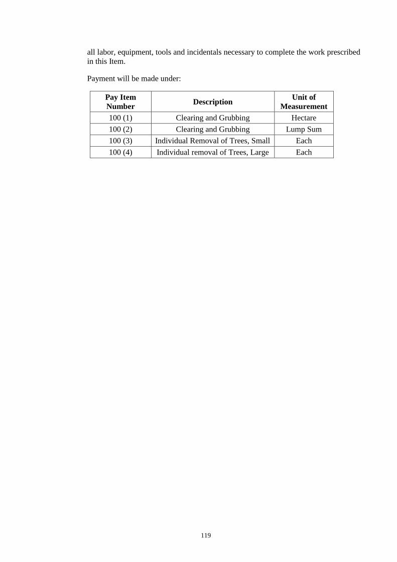
Payment will be made under:
Pay Item
Number Description
Unit of
Measurement
100 (1) Clearing and Grubbing Hectare
100 (2) Clearing and Grubbing Lump Sum
100 (3) Individual Removal of Trees, Small Each
100 (4) Individual removal of Trees, Large Each
120
ITEM 102 – EXCAVATION
102.1 Description
This Item shall consist of roadway and drainage and borrow excavation and the
disposal of material in accordance with this Specification and in conformity with the
lines, grades and dimensions shown on the Plans or established by the Engineer.
102.1.1 Roadway Excavation
Roadway excavation will include excavation and grading for roadways,