22-1 18% 20% 7% 3% 3% 22 Chapter CXXXX 40757 Page 1 03/18/08 MD Two-Dimensional Drawing objectives After completing this chapter, you should be able to ● Identify manual drafting tools used in drawing creation ● Apply the techniques of geometric construction in manual drafting ● Utilize basic CAD system commands and processes in creat- ing a drawing ● Create a manually drafted or CAD-based orthographic pro- jection drawing ● Develop a section and auxiliary view drawing using CAD ● Identify several common issues that occur in CAD drafting 22 22 Chapter Cxxxx 40757 3/19/08 10:24 AM Page 1
Transcript
122-1
18%
20%
7%3% 3%
22 C
hapt
er
CXX
XX 4
0757
Pa
ge 1
03/1
8/08
MD
Two-Dimensional Drawing
objectivesAfter completing this chapter, you should be able to● Identify manual drafting tools used in drawing creation● Apply the techniques of geometric construction in manual
drafting● Utilize basic CAD system commands and processes in creat-
ing a drawing● Create a manually drafted or CAD-based orthographic pro-
jection drawing● Develop a section and auxiliary view drawing using CAD● Identify several common issues that occur in CAD drafting
22
22 Chapter Cxxxx 40757 3/19/08 10:24 AM Page 1
22-2 sectionfive Advanced Topics in Engineering Graphics22 C
hapter CXXXX 40757 Page 2
03/18/08 MD
T wo-dimensional (2-D) drawings have been the mainstay of graphicalcommunication for mechanical, civil, and other engineering fields for cen-turies. Although the use of computer-based three-dimensional (solid mod-
eling) is predominant in the United States and Western Europe, most of the worlddepends heavily on 2-D drawings for the transfer of engineering geometry infor-mation. Two-dimensional drawing, whether done by hand or with the assistance ofa computer, will be around for a very long time. In some areas of the world, it isstill the only way that engineering graphics are created and used. There is atremendous amount of legacy data in 2-D format that must be edited using thesame methods used to create the data. In some types of industries, 2-D drawing isstill the only acceptable means of presenting engineering graphics.
Two-dimensional drawings are still heavily utilized in some industries in theUnited States. The breakdown is in two areas: manually drawn 2-D drawings and2-D drawings developed through computer-aided design (CAD). Almost all 2-Ddrawings that are created today to build or manufacture objects are done usingCAD tools; however, many basic skill sets can be replicated in both manual draw-ings and CAD drawings.
22.01introduction
Manual 2-D DrawingsThis section provides a glimpse into the skills needed to create drawings manually.Three components are required to create high-quality drawings. First, tools are neededto create neat drawings and lettering. Second, dexterity and drawing technique play apart in consistently developing quality work. Finally, practice and experience areneeded to create drawings in a timely and efficient manner.
22.02.01 Manual Drawing ToolsThe process of creating a 2-D drawing manually is sometimes called drafting. The fol-lowing list and Figure 22.01 contain some of the basic tools used in the creation of 2-D manual drawings. These tools are sometimes called drafting instrumentsbecause they are made with great precision and are used to create accurate graphics.
Brush—used to keep the drawing area clean by removing dry erase material, erasershavings, and other debris.
Compass—used to create accurate circles and arcs and used in the layout of geomet-ric shapes. To use a compass, open it to the desired radius using a scale as a guide.Carefully place the pointed (anchor) end of the compass through the paper into thedrafting table. For good compass technique, tilt the compass to one side and allowthe lead to follow the compass around the circle. The lead in the compass should besharpened often to ensure clean, even arcs. To darken an arc, make multiple passesinstead of pressing down on the compass.
Dividers—used to lay out and transfer distances. They can also be used to breaklonger object segments into equal distances. A scale can be used to help set dividermeasurements.
Drafting Machine—a tool clamped to a drafting table that holds two straightedges(used to draw and measure lines) usually at 90 degrees relative to each other. Thestraightedges can be rotated to any angle desired and moved about the table whilethe desired angle is maintained.
Drafting Table—a large, rectangular, flat table with a smooth surface and straightsides. The sides of the table are parallel and perpendicular to each other to aid inthe drawing of horizontal and vertical lines with excellent precision.
22.02
22 Chapter Cxxxx 40757 3/19/08 10:24 AM Page 2
Drafting Vellum—a high-quality paper that is abrasion-resistant and stable overlong periods of time. It allows errantly drawn items to be erased with little ghosting.
Dry Erase Bag—holds an inert powder that is layered on a drawing to preventsmudges. The bag is occasionally kneaded and tapped on the drawing so tools willglide over the surface.
Eraser—used to remove errant lead marks. Drafting erasers are usually not the com-mon pink rubber variety, but rather a soft white plastic type, which is less abrasiveto drawing surfaces.
Eraser Shield—used to protect areas of a drawing while an eraser is being used.
French Curve—used to create smooth curves through a set of points by aligning thepart of the curve that best fits the points.
Leads—thin rods of graphite bound in a clay base and sharpened for use in markinglines, text, and other art on a drawing. Drawing leads vary in darkness based on thegrading, as shown in Figure 22.02. The familiar #2 yellow pencil, which contains #2 grade graphite, draws a medium dark line. The higher the lead grade number, theharder the lead and the lighter the line produced. As the lead grade number decreases,the graphite composition gets softer, resulting in a darker line. Pencil lead grades andtheir equivalent drafting lead grades are shown in Figure 22.03.
chapter 22 Two-Dimensional Drawing 22-322
Cha
pter
C
XXXX
407
57
Page
303
/18/
08 M
D
FIGURE 22.01. Manual drafting tools.
FIGURE 22.02. Various shades of lead marks used in drafting.
22 Chapter Cxxxx 40757 3/19/08 10:24 AM Page 3
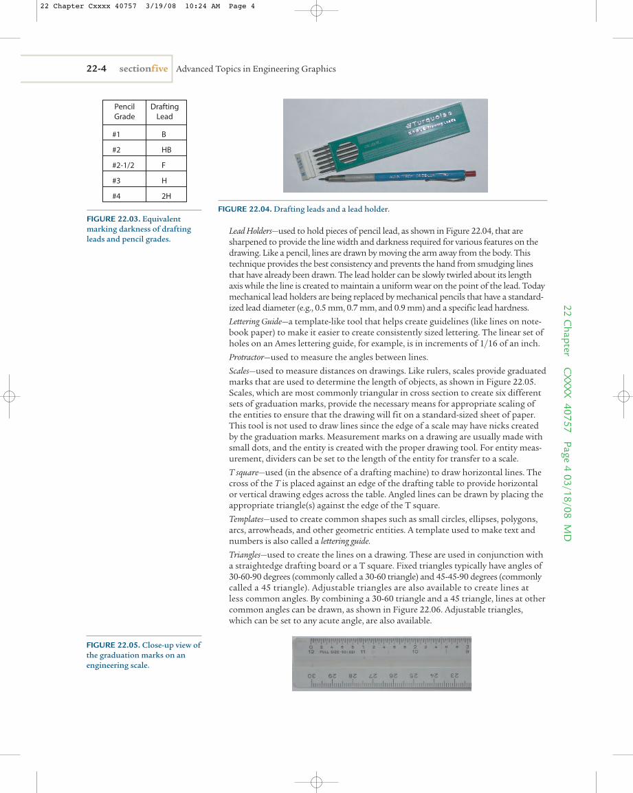
Lead Holders—used to hold pieces of pencil lead, as shown in Figure 22.04, that aresharpened to provide the line width and darkness required for various features on thedrawing. Like a pencil, lines are drawn by moving the arm away from the body. Thistechnique provides the best consistency and prevents the hand from smudging linesthat have already been drawn. The lead holder can be slowly twirled about its lengthaxis while the line is created to maintain a uniform wear on the point of the lead. Todaymechanical lead holders are being replaced by mechanical pencils that have a standard-ized lead diameter (e.g., 0.5 mm, 0.7 mm, and 0.9 mm) and a specific lead hardness.
Lettering Guide—a template-like tool that helps create guidelines (like lines on note-book paper) to make it easier to create consistently sized lettering. The linear set ofholes on an Ames lettering guide, for example, is in increments of 1/16 of an inch.
Protractor—used to measure the angles between lines.
Scales—used to measure distances on drawings. Like rulers, scales provide graduatedmarks that are used to determine the length of objects, as shown in Figure 22.05.Scales, which are most commonly triangular in cross section to create six differentsets of graduation marks, provide the necessary means for appropriate scaling ofthe entities to ensure that the drawing will fit on a standard-sized sheet of paper.This tool is not used to draw lines since the edge of a scale may have nicks createdby the graduation marks. Measurement marks on a drawing are usually made withsmall dots, and the entity is created with the proper drawing tool. For entity meas-urement, dividers can be set to the length of the entity for transfer to a scale.
T square—used (in the absence of a drafting machine) to draw horizontal lines. Thecross of the T is placed against an edge of the drafting table to provide horizontalor vertical drawing edges across the table. Angled lines can be drawn by placing theappropriate triangle(s) against the edge of the T square.
Templates—used to create common shapes such as small circles, ellipses, polygons,arcs, arrowheads, and other geometric entities. A template used to make text andnumbers is also called a lettering guide.
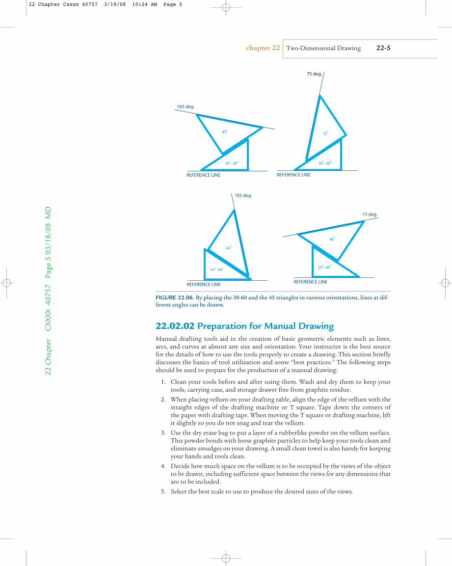
Triangles—used to create the lines on a drawing. These are used in conjunction witha straightedge drafting board or a T square. Fixed triangles typically have angles of30-60-90 degrees (commonly called a 30-60 triangle) and 45-45-90 degrees (commonlycalled a 45 triangle). Adjustable triangles are also available to create lines at less common angles. By combining a 30-60 triangle and a 45 triangle, lines at othercommon angles can be drawn, as shown in Figure 22.06. Adjustable triangles,which can be set to any acute angle, are also available.
22-4 sectionfive Advanced Topics in Engineering Graphics22 C
hapter CXXXX 40757 Page 4
03/18/08 MD
FIGURE 22.04. Drafting leads and a lead holder.
FIGURE 22.05. Close-up view ofthe graduation marks on anengineering scale.
#1 B
#2
#2-1/2
#3
#4
HB
F
H
2H
PencilGrade
DraftingLead
FIGURE 22.03. Equivalentmarking darkness of draftingleads and pencil grades.
22 Chapter Cxxxx 40757 3/19/08 10:24 AM Page 4
22.02.02 Preparation for Manual DrawingManual drafting tools aid in the creation of basic geometric elements such as lines,arcs, and curves at almost any size and orientation. Your instructor is the best sourcefor the details of how to use the tools properly to create a drawing. This section brieflydiscusses the basics of tool utilization and some “best practices.” The following stepsshould be used to prepare for the production of a manual drawing:
1. Clean your tools before and after using them. Wash and dry them to keep yourtools, carrying case, and storage drawer free from graphite residue.
2. When placing vellum on your drafting table, align the edge of the vellum with thestraight edges of the drafting machine or T square. Tape down the corners of the paper with drafting tape. When moving the T square or drafting machine, liftit slightly so you do not snag and tear the vellum.
3. Use the dry erase bag to put a layer of a rubberlike powder on the vellum surface.This powder bonds with loose graphite particles to help keep your tools clean andeliminate smudges on your drawing. A small clean towel is also handy for keepingyour hands and tools clean.
4. Decide how much space on the vellum is to be occupied by the views of the objectto be drawn, including sufficient space between the views for any dimensions thatare to be included.
5. Select the best scale to use to produce the desired sizes of the views.
chapter 22 Two-Dimensional Drawing 22-522
Cha
pter
C
XXXX
407
57
Page
503
/18/
08 M
D
REFERENCE LINE REFERENCE LINE
REFERENCE LINE REFERENCE LINE
75 deg.
165 deg.
105 deg.
15 deg.
FIGURE 22.06. By placing the 30-60 and the 45 triangles in various orientations, lines at dif-ferent angles can be drawn.
22 Chapter Cxxxx 40757 3/19/08 10:24 AM Page 5
6. Once the view placement has been determined, create the exterior shape of theobject views using projection rules and proper dimension scaling.
7. Use triangles or a protractor to verify angles after they have been drawn.
8. Sharpen your drawing leads often as the accuracy of your drawing may depend ona sharp lead.
9. Place an additional piece of paper or vellum under your drawing hand to avoidsmudges. Try not to touch the surface of the drawing with your hand or put fin-gerprints on the drawing surface. Oils from your skin may be absorbed by the vel-lum and leave a stain.
10. Use the eraser template when erasing. Lay the template on top of your drawing,exposing the area that needs to be erased through the proper-sized opening. Eraselightly through the opening to remove the errant line.
11. Use a circle template for small circles and arcs as this is faster and easier thanusing a compass (assuming the proper size circle is available).
12. Use a template when creating small polygons (e.g., for hex head bolts) and ellipses as thisis the fastest way to draw these objects (assuming the proper size object is available).
13. Use special lettering templates, if necessary and if available, to assist in lettering.Lettering is only similar to printing. You can be a poor printer but still have goodlettering.
14. When finished with your drawing, lightly rub the drawing with your dry erase bagto pick up any loose graphite. Then clean your drawing using a brush to removeall of the dry erase powder.
22.02.03 Making a Simple Manual DrawingNow that you have been introduced to the drawing preparation process and some ofthe basic geometry creation skills, this section walks you through a basic drawing of theflat gasket shown in Figure 22.07. Here is the equipment needed:■ T square or drafting machine■ Triangle■ Scale■ Circle template■ Eraser■ Eraser template
22-6 sectionfive Advanced Topics in Engineering Graphics22 C
hapter CXXXX 40757 Page 6
03/18/08 MD
4.00
2.00
Ø 1.00R .50 TYP
FIGURE 22.07. The goal is to re-create a drawing of this flat gasket.
22 Chapter Cxxxx 40757 3/19/08 10:24 AM Page 6
You will begin with the basic steps of drawing straight horizontal and vertical lineson a sheet of paper to outline the object. Use a lead grade that is harder than #4 (orharder than 2H). If erasing is needed, use a light touch to prevent smearing. You will goback over the final drawing with a softer lead grade to create the final darker image.Whether you are using a T square or a drafting machine, the general process is thesame. If you are using a T square, make sure you hold the cross of the T firmly againstthe edge of the drafting table. Large errors can occur when you try to use one hand tohold a T square loosely in an approximate position while drawing lines with the otherhand. Align your T square or drafting machine and draw a horizontal line at least 4 inches long. Use the scale to make very light marks to indicate a length of 4 inchesalong the line. These steps are shown in Figure 22.08.
chapter 22 Two-Dimensional Drawing 22-722
Cha
pter
C
XXXX
407
57
Page
703
/18/
08 M
D
4 inches
FIGURE 22.08. Drawing andmarking a horizontal line,which will be the bottom edgeof the gasket.
22 Chapter Cxxxx 40757 3/19/08 10:24 AM Page 7
Set the triangle firmly against the straight edge of the T square or drafting machine.To create the right edge of the gasket, place the perpendicular edge of the triangle on the right end of the 4-inch line mark. Draw a light vertical line at least 2 inches long.Use the scale to mark a 2-inch distance above the 4-inch line, as shown in Figure 22.09.Create the left edge of the gasket in a similar fashion, as shown in Figure 22.10.
22-8 sectionfive Advanced Topics in Engineering Graphics22 C
hapter CXXXX 40757 Page 8
03/18/08 MD
2 inches
FIGURE 22.09. Drawing and marking a vertical line, which will be the right edge of the gasket.
22 Chapter Cxxxx 40757 3/19/08 10:24 AM Page 8
Using the T square or drafting machine, lightly draw the top edge of the gasket byconnecting the two vertical lines at their 2-inch marks using a horizontal line, as shownin Figure 22.11.
The circle template will be used to create the rounded edges. Select the tem-plate circle with the diameter of the arc needed, which is 1 inch (to provide a radius
chapter 22 Two-Dimensional Drawing 22-922
Cha
pter
C
XXXX
407
57
Page
903
/18/
08 M
D
2 inches
FIGURE 22.10. Drawing and marking another vertical line, which will be the left edge of the gasket.
22 Chapter Cxxxx 40757 3/19/08 10:24 AM Page 9
of 0.5 inch at the corners of the gasket). Use the template to create a 0.5-inch radiusarc that is tangent to horizontal and vertical lines at each corner of the gasket, asshown in Figure 22.12.
To locate the center hole of the gasket, use the scale to mark the center of the bot-tom horizontal line (i.e., 2 inches from the left mark on this line). Lightly draw a verti-cal line through the outline of the gasket at this 2-inch location. Then use the scale tomark the center of the right vertical line (i.e., 1 inch from the bottom horizontal line).
22-10 sectionfive Advanced Topics in Engineering Graphics22 C
hapter CXXXX 40757 Page 10
03/18/08 MD
FIGURE 22.11. Drawing a horizontal line, which will be the top edge of the gasket, at the marks.
22 Chapter Cxxxx 40757 3/19/08 10:25 AM Page 10
Lightly draw a horizontal line through the outline of the gasket at this 1-inch location,as shown in Figure 22.13. The center of the hole will be located at the intersection ofthe horizontal and vertical lines just drawn through the center of the gasket outline.
The circle template will have centerlines on the edges of the 1-inch hole. Alignthese centerlines to the vertical and horizontal lines, locating the center of the circle,and draw the 1-inch circle as shown in Figure 22.14. Using the marks on the on the 1" diameter circle template, again position the template so the marks line up on the lightly created lines; then draw the circle.
chapter 22 Two-Dimensional Drawing 22-1122
Cha
pter
C
XXXX
407
57
Page
11
03/1
8/08
MD
Use the 1-inchdiameter size
FIGURE 22.12. Using a circle template to add the rounded corners.
22 Chapter Cxxxx 40757 3/19/08 10:25 AM Page 11
Use the eraser and eraser template to remove the corners of the rectangle back to the radius locations, as shown in Figure 22.15. A softer lead is then used to trace overthe lightly created lines to complete the construction of the gasket.
Finally, annotations are added. Annotations include the numbers, lines, and arrowsused to show the sizes of various features on the part. The numbers, or dimensions, areadded first, as shown in Figure 22.16. Lettering should be between 1/8 inch and 1/4 inchin height. If your lettering is neat, the numbers can be drawn freehand. Otherwise, a let-tering template should be used.
22-12 sectionfive Advanced Topics in Engineering Graphics22 C
hapter CXXXX 40757 Page 12
03/18/08 MD
1 inch
2 inches
FIGURE 22.13. Locating and marking the center of the hole.
22 Chapter Cxxxx 40757 3/19/08 10:25 AM Page 12
The extension lines and dimension lines are then added as shown in Figure 22.17with the assistance of the drafting machine or T square and triangle. Remember toleave a small space of about 1/16 inch between the extension lines and the features theydefine. This space helps distinguish between lines that are a part of the object and linesthat are a part of the annotation. This small amount of space between the dimensionlines and the extension lines allows neater arrowheads to be drawn, as shown in Figure 22.18. Arrowheads can be drawn freehand if it can be done neatly or drawn withthe assistance of an arrowhead template.
Lines with arrowheads that point from a dimension directly to a feature, as shownfor the circle and arcs in Figure 22.19, are called leaders.
chapter 22 Two-Dimensional Drawing 22-1322
Cha
pter
C
XXXX
407
57
Page
13
03/1
8/08
MD
FIGURE 22.14. Aligning the circle template and making the center hole.
22 Chapter Cxxxx 40757 3/19/08 10:25 AM Page 13
22-14 sectionfive Advanced Topics in Engineering Graphics22 C
hapter CXXXX 40757 Page 14
03/18/08 MD
FIGURE 22.15. Erasing the construction lines and darkeningthe outline.
4.00
2.00
Ø 1.00R .50 TYP
FIGURE 22.16. Dimensions are added.
22 Chapter Cxxxx 40757 3/19/08 10:25 AM Page 14
chapter 22 Two-Dimensional Drawing 22-1522
Cha
pter
C
XXXX
407
57
Page
15
03/1
8/08
MD
4.00
2.00
Ø 1.00R .50 TYP
FIGURE 22.17. Extension lines,dimension lines, and centerlinesare added.
4.00
2.00
Ø 1.00R .50 TYP
FIGURE 22.18. Arrowheads areadded to the dimension lines.
4.00
2.00
Ø 1.00R .50 TYP
FIGURE 22.19. Leaders are added.
22 Chapter Cxxxx 40757 3/19/08 10:25 AM Page 15
Two-Dimensional CAD DrawingsTwo-dimensional CAD drawings are similar to 2-D manually created drawings in thatboth are a collection of lines, arcs, circles, and other 2-D geometric elements that aregrouped to represent the image of an object. With 2-D CAD, however, the manualdrawing tools are replaced by a computer, as shown in Figure 22.20, and the vellum isreplaced with a software file. This section of the chapter covers the basic practices ofcreating 2-D CAD-based drawings. Most 2-D CAD software uses similar features, com-mands, and geometry creation methods, although the precise terminology may vary.
22.03.01 Basic Setup CommandsThe basic setup commands are used to prepare a drawing by specifying various userpreferences for parameters such as the overall size of the drawing area, units of meas-urement, sizes of fonts, formats of numbers, and special shortcuts and aids used tospeed up the process of creating drawings. Many companies have common settings forthese commands to make it easy for different people to work on the same drawing.Following are some common setup commands and their functions:
Angle Control—helps draw lines at specific angular orientations by forcing, or snapping, any line drawn near specified angular intervals to align to those intervals.This command setting aids in the drawing of angled lines by eliminating the need toenter the values of certain angles. Angle control, sometimes called polar tracking, is alsouseful for drawing horizontal and vertical lines. An example of a dialog box used tospecify angular increments for polar tracking is shown in Figure 22.21.
Layer—manages how objects or entities are grouped for convenience within thedrawing. Layers also control color, line type, and line weights and controlwhether the objects on the layer appear on a drawing when it is plotted. It iscommon, for example, for an annotation to be kept on a separate layer from thegeometry of the object. The annotation layer can then be temporarily turned offto reduce the complexity of the drawing when only the geometry needs to beviewed. An example of a dialog box used to control layer properties is shown inFigure 22.22.
Limits—defines the overall size of the drawing area, which is often determined bythe size of the sheet when the drawing is printed at its full size.
22-16 sectionfive Advanced Topics in Engineering Graphics22 C
hapter CXXXX 40757 Page 16
03/18/08 MD
22.03
FIGURE 22.20. CAD drawings require the use of a computer and software to create the graphics.
22 Chapter Cxxxx 40757 3/19/08 10:25 AM Page 16
Object Snap—helps specify the exact locations of selection points by forcing anyselection point near certain types of geometry locations to become coincident withthose locations. This command setting aids in the accurate placement of entities orfinishing points. Typical selection point locations include the following:
■ Center: locates to the centers of circles and arcs■ Midpoint: locates to the midpoint of lines and arcs■ Endpoint: locates the endpoints of lines and arcs■ Perpendicular: after the first endpoint of a line has been specified, locates the
second endpoint to draw the line perpendicular to another line■ Intersection: locates the nearest intersection of two objects■ Apparent Intersection: locates the intersection of two entities that would meet if
those entities were extended■ Parallel: after the first endpoint of a line has been specified, locates the second
endpoint to draw the line parallel to another line■ Quadrant: locates the 0°, 90°, 180°, and 270° positions on a circle■ Tangent: locates the tangent positions of a line, an arc, or a circle with another
arc or circle
Examples of various symbols used to notify the user that an object snap point hasbeen specified are shown in Figure 22.23.
chapter 22 Two-Dimensional Drawing 22-1722
Cha
pter
C
XXXX
407
57
Page
17
03/1
8/08
MD
FIGURE 22.21. A dialog box used to set up angular control in the user interface of a 2-D CAD software product.
FIGURE 22.22. A dialog box used to set up layer control in the user interface of a 2-D CAD software product.
22 Chapter Cxxxx 40757 3/19/08 10:25 AM Page 17
Precision—specifies the decimal place accuracy of dimensions when they are addedto a drawing. This setup command does not affect precision of the location or thesize of drawn entities.
Text Format—specifies the font and size of the letters and numbers used to annotatethe drawing.
Units—defines the units of measurement in the drawing. For example, decimalinches are commonly used in manufacturing drawings, whereas fractional inchesare commonly found in construction and architectural drawings. An example of adialog box used to specify units is shown in Figure 22.24.
22.03.02 Basic Creation CommandsThe basic entity creation commands, listed and detailed next, are found on most 2-D CAD programs. The procedures for their use are slightly different for each softwaretool, but the overall utilization concept is the same. Typically, these commands can beinitiated by entering a key word or a letter from the keyboard or by selecting a shortcuticon on the screen menu of the program.
Arc—creates sections of circles.
Chamfer—replaces the intersection of two entities with a line segment of a specifiedlength and orientation.
22-18 sectionfive Advanced Topics in Engineering Graphics22 C
hapter CXXXX 40757 Page 18
03/18/08 MD
Endpoint
Midpoint
Center
Node
Quadrant
Extension
Tangent
Intersection
Perpendicular
Parallel
(a) (b) (c)
Indicates active snap
First point established
Second point snapsto existing entity
Endpoint
Perpendicularpoint Midpoint
FIGURE 22.23. The endpoint ofthe line being created can snap toany endpoint (a), perpendicularpoint (b), or midpoint (c) ofanother entity. Different symbolsare used to indicate the particularsnap geometry engaged.
FIGURE 22.24. Part of a dialog box used to specify the type and precision of units to be usedon the drawing.
22 Chapter Cxxxx 40757 3/19/08 10:25 AM Page 18
Circle—creates a circle.
Dimension—creates the wide variety of dimensions that are used to specify the exactsizes and locations of points, lines, and arcs. The common types of dimensions thatcan be created are as follows:
Angular—specifies the angle between two lines.
Aligned—specifies the shortest distance between two points regardless of angularorientation.
Baseline—specifies sizes and locations from a common extension line.
Leader—creates annotations that are directed to a specific feature.
Linear—specifies sizes and locations in horizontal and vertical directions.
Ordinate—specifies sizes and locations from a newly defined coordinate system.
Radial/Diameter—specifies the diameters of circles and the radii of arcs.
Fillet (or Round)—replaces the intersection of two entities with an arc of a speci-fied radius.
Hatch—fills the area inside a closed loop with a specified pattern, color, or shade.
Line—creates straight lines at any orientation. Examples of lines created by keyboardentries on the drawing screen are shown in Figure 22.25. Note that decimal inchunits are used in one case and fractional inch units are used in the other case.
Point—creates a point at a specified location.
Text—creates letters, numbers, and symbols.
chapter 22 Two-Dimensional Drawing 22-1922
Cha
pter
C
XXXX
407
57
Page
19
03/1
8/08
MD
2.3520
15 deg
17 deg
1'- 4 1/2"
(a)
(b)
First point established
Location ofpointing device
Value enteredfrom keyboard
Value enteredfrom keyboard
FIGURE 22.25. The creation of lines with polar coordinates entered from the keyboard.Decimal units (engineering) are used in (a). Fractional units (architectural) are used in (b).
22 Chapter Cxxxx 40757 3/19/08 10:25 AM Page 19
22.03.03 Basic Editing CommandsThe basic editing commands are used to modify entities that have already been cre-ated. As with the creation commands, the procedures for using editing commands areslightly different for each software tool, but the overall utilization concept is the same.Typically, these commands can be initiated by entering a key word or a letter from thekeyboard or by selecting a shortcut icon on the screen menu of the program.
Copy—is similar to the Move command except that this tool creates new objects atthe second location and keeps the original objects in the original location.
Divide—places points at equally spaced intervals along a selected object.
Erase—removes the selected objects from the drawing.
Extend—lengthens an object until it intersects a selected boundary object.
Move—relocates the selected entities from one location in a drawing to anotherlocation within the same drawing.
Offset—creates a new object that is placed at a constant prespecified distance fromthe original object. This command is commonly used to create parallel lines andconcentric circles.
Pattern (or array)—copies selected objects and creates a circular group of themaround a selected point or creates a rectangular group of them extending from aselected point.
Rotate—changes the orientation angle of selected objects about a selected rotation center.
Scale—changes the overall size of selected objects. A new scale number above thevalue of 1.00 will increase the size of the objects. A new scale number below 1.00will decrease the size of the objects.
Trim—removes that part of a selected object that extends beyond its intersectionwith a selected boundary object.
22.03.04 Making a Simple 2-D CAD DrawingThe use of the setup, creation, and editing commands to make a simple 2-D CAD draw-ing is now demonstrated through the creation of a drawing of the gasket shown inFigure 22.26, which was created earlier using manual techniques. First, the setup com-mands are specified, as shown next.
Angle control—specify a snap to every 90°.
Layer—specify a single layer.
Limits—specify a letter-sized (8.5" × 11") drawing limit with landscape orientation(i.e., a size A drawing).
Object snap—snap to endpoints, midpoints, and intersections.
Precision—specify accuracy to two decimal places.
Text format—specify a drafting font that is 0.25 inch in height.
Units—specify decimal inches.
If this setup will often be used for future drawings, it would be wise to save the drawingas a template. Template files can then be used to create drawings with the desired setup com-mand specifications already in place so the specifications do not need tobe entered again.
22-20 sectionfive Advanced Topics in Engineering Graphics22 C
hapter CXXXX 40757 Page 20
03/18/08 MD
4.7521 >0 degFIGURE 22.26. The 2-D CADdrawing of the gasket begins witha horizontal line. The placementand length are not important aslong as the line is horizontal andlonger than 4 inches.
22 Chapter Cxxxx 40757 3/19/08 10:25 AM Page 20
chapter 22 Two-Dimensional Drawing 22-2122
Cha
pter
C
XXXX
407
57
Page
21
03/1
8/08
MD
3.2502 >90 deg
OFFSET, 2 inches
Create a horizontal line using the Line command as shown in Figure 22.26. The lineshould be at least 4 inches long and snap to the horizontal position. Next, create a verticalline from the right end of the horizontal line as shown in Figure 22.27. The vertical lineshould be at least 2 inches long.
Specifying an offset value of 4 inches, use the Offset command to create a copyof the vertical line to the left of the original vertical line as shown in Figure 22.28.Use the Offset command again, this time specifying an offset value of 2 inches, tocreate a copy of the horizontal line above the original horizontal line as shown inFigure 22.29.
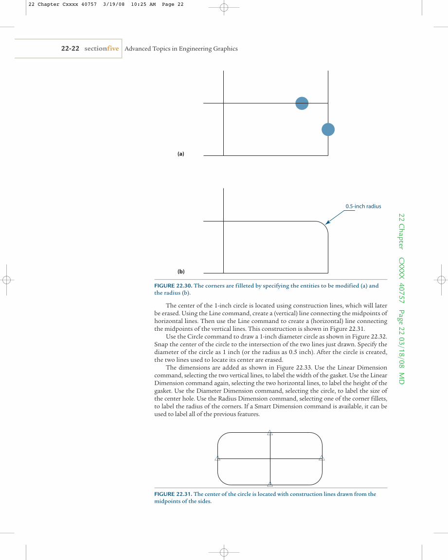
Use the Fillet command to round the corners of the enclosed rectangle as shown inFigure 22.30. The radius of the fillet should be specified as 0.5 inch. Select the edges ofthe rectangle that are to be trimmed to create the fillet. Do this for all four corners of theenclosed rectangle.
OFFSET, 4 inchesFIGURE 22.29. The vertical lineis offset by 4 inches in thedirection shown.
FIGURE 22.28. The horizontalline is offset by 2 inches in thedirection shown.
FIGURE 22.27. A vertical line isadded at one endpoint. Thelength is not important as longas the line is vertical and longerthan 2 inches.
22 Chapter Cxxxx 40757 3/19/08 10:25 AM Page 21
The center of the 1-inch circle is located using construction lines, which will laterbe erased. Using the Line command, create a (vertical) line connecting the midpoints ofhorizontal lines. Then use the Line command to create a (horizontal) line connectingthe midpoints of the vertical lines. This construction is shown in Figure 22.31.
Use the Circle command to draw a 1-inch diameter circle as shown in Figure 22.32.Snap the center of the circle to the intersection of the two lines just drawn. Specify thediameter of the circle as 1 inch (or the radius as 0.5 inch). After the circle is created,the two lines used to locate its center are erased.
The dimensions are added as shown in Figure 22.33. Use the Linear Dimensioncommand, selecting the two vertical lines, to label the width of the gasket. Use the LinearDimension command again, selecting the two horizontal lines, to label the height of thegasket. Use the Diameter Dimension command, selecting the circle, to label the size ofthe center hole. Use the Radius Dimension command, selecting one of the corner fillets,to label the radius of the corners. If a Smart Dimension command is available, it can beused to label all of the previous features.
22-22 sectionfive Advanced Topics in Engineering Graphics22 C
hapter CXXXX 40757 Page 22
03/18/08 MD
(a)
(b)
0.5-inch radius
FIGURE 22.30. The corners are filleted by specifying the entities to be modified (a) andthe radius (b).
FIGURE 22.31. The center of the circle is located with construction lines drawn from themidpoints of the sides.
22 Chapter Cxxxx 40757 3/19/08 10:25 AM Page 22
22.03.05 Manually Drawn versus 2-D CAD Drawn The current trend is toward increased usage and dependence on 2-D CAD-based toolsfor creating and editing all types and styles of technical drawings. Manually createddrawings have the advantage of requiring simpler and less expensive tools than 2-DCAD-created drawings. Manual drawing tools are also simpler and easier to use. Two-dimensional CAD-created drawings require the use of a computer and the appropriatesoftware. Mastering the use of the software typically requires longer and more sophisti-cated training than mastering the use of manual drawing instruments. However, oncemastered, 2-D CAD-based drawings have many advantages over manually createddrawings. Two-dimensional CAD-created drawings typically can be produced morequickly than manually created drawings. Manually created drawings are prone to inac-curacies caused by errors in tool placement, measurement, and imperfect drawing tech-nique. Two-dimensional CAD-created drawings are easier to edit compared to erasingentities on a manually created drawing, which is a time-consuming process. Finally,because 2-D CAD-created drawings can be saved as computer files, they require lessstorage space and can be reproduced and transmitted quickly and easily.
Making a Typical 2-D CAD DrawingA more sophisticated drawing is shown in Figure 22.34, which shows the front andright-side views of a flange. The right-side view is presented as a half section. The stepsin the creation of a 2-D CAD-based drawing of this flange are detailed to demonstratehow additional 2-D CAD settings and commands can be used.
chapter 22 Two-Dimensional Drawing 22-2322
Cha
pter
C
XXXX
407
57
Page
23
03/1
8/08
MD
1-inch diameter
FIGURE 22.32. The center of the circle snaps to the intersection of the construction lines.The diameter is specified. The construction lines can then be erased.
4.00
2.00
2.00
1.00
Ø 1.00R 0.5 TYP
FIGURE 22.33. The dimensions are added. Adding dimensions to circles and radii usuallyinserts their centerlines.
22.04
22 Chapter Cxxxx 40757 3/19/08 10:25 AM Page 23
First, the setup commands are specified as shown below. This setup is the same asthat used in the previous example except for the additional layers and object snaps. Ifthe setup used in the previous example was saved as a template, that template could berecalled, modified, and reused for this example.
Angle control—specify a snap to every 90°.
Layer—specify five layers.
Limits—specify a letter-sized (8.5" × 11") drawing limit with landscape orientation(i.e., a size A drawing).
Object snap—snap to endpoints, midpoints, intersections, and tangents.
Precision—specify accuracy to two decimal places.
Text format—specify a drafting font that is 0.25 inch in height.
Units—specify decimal inches.
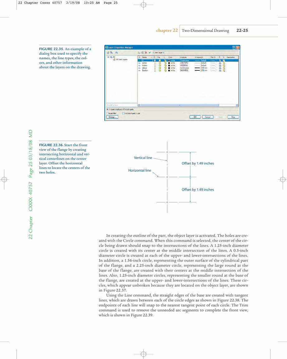
The five layers shown in the example dialog box in Figure 22.35 are used to organ-ize different aspects of the drawing. Entities used to create the dimensions are groupedinto a layer named “0,” the centerlines in a layer named “center,” the hidden lines in alayer named “hidden,” the outline of the object in a layer called “object,” and the sec-tion lines in a layer called “section.” The advantage of using five separate layers is thatdifferent line styles and colors may be assigned to each layer, as in the case of the flangedrawing. For example, an entity created on the center layer will appear as a sequence ofshort and long dashes, whereas an entity created on the object layer will appear unbro-ken. An entity on the hidden layer will appear with dashed lines. In addition, the objectlines and section lines should be slightly thicker than the default line type. The colorand line style of every entity in a layer can be changed, if needed, in a single operation bychanging the default settings in that layer.
Once the setup is complete, the front and right-side views can be created. The cen-ter layer is activated, and the Line command is used to draw intersecting horizontal andvertical lines as shown in Figure 22.36. These lines automatically appear as centerlinesbecause they have been drawn on the center layer. These lines will be used to locate thelarge hole on the front view. Next, use the Offset command to create a copy of the hor-izontal line 1.49 inches above the original line; then use Offset again to create a copy1.49 inches below the original line. The intersection of the vertical line with the twonew horizontal lines will be used to locate the centers of the two smaller holes on thefront view.
22-24 sectionfive Advanced Topics in Engineering Graphics22 C
hapter CXXXX 40757 Page 24
03/18/08 MD
2X Ø .50
Ø 1.25
R 1.13
2X R .63
2.99
1.49
Ø 1.56
.38
2X .06
2X .25
FIGURE 22.34. The front andright-side views of a flange. Theright-side view is presented as ahalf section.
22 Chapter Cxxxx 40757 3/19/08 10:25 AM Page 24
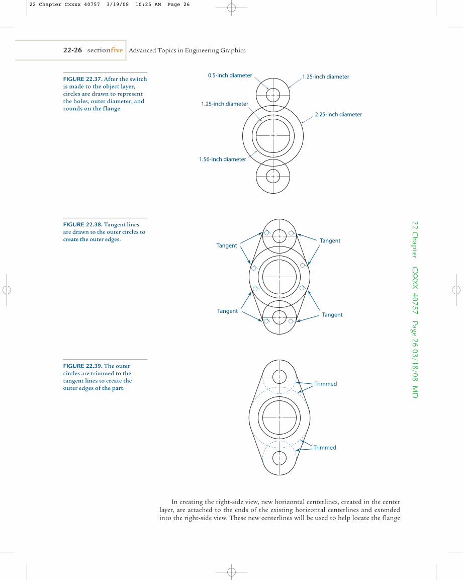
In creating the outline of the part, the object layer is activated. The holes are cre-ated with the Circle command. When this command is selected, the center of the cir-cle being drawn should snap to the intersections of the lines. A 1.25-inch diametercircle is created with its center at the middle intersection of the lines. A 0.5-inchdiameter circle is created at each of the upper- and lower-intersections of the lines.In addition, a 1.56-inch circle, representing the outer surface of the cylindrical partof the flange, and a 2.25-inch diameter circle, representing the large round at thebase of the flange, are created with their centers at the middle intersection of thelines. Also, 1.25-inch diameter circles, representing the smaller round at the base ofthe flange, are created at the upper- and lower-intersections of the lines. These cir-cles, which appear unbroken because they are located on the object layer, are shownin Figure 22.37.
Using the Line command, the straight edges of the base are created with tangentlines, which are drawn between each of the circle edges as shown in Figure 22.38. Theendpoints of each line will snap to the nearest tangent point of each circle. The Trimcommand is used to remove the unneeded arc segments to complete the front view,which is shown in Figure 22.39.
chapter 22 Two-Dimensional Drawing 22-2522
Cha
pter
C
XXXX
407
57
Page
25
03/1
8/08
MD
FIGURE 22.35. An example of adialog box used to specify thenames, the line types, the col-ors, and other informationabout the layers on the drawing.
Horizontal line
Vertical line
Offset by 1.49 inches
Offset by 1.49 inches
FIGURE 22.36. Start the frontview of the flange by creatingintersecting horizontal and ver-tical centerlines on the centerlayer. Offset the horizontal lines to locate the centers of thetwo holes.
22 Chapter Cxxxx 40757 3/19/08 10:25 AM Page 25
22-26 sectionfive Advanced Topics in Engineering Graphics22 C
hapter CXXXX 40757 Page 26
03/18/08 MD
1.25-inch diameter0.5-inch diameter
1.25-inch diameter
1.56-inch diameter
2.25-inch diameter
FIGURE 22.37. After the switchis made to the object layer, circles are drawn to representthe holes, outer diameter, androunds on the flange.
Tangent
Tangent
Tangent
Tangent
FIGURE 22.38. Tangent linesare drawn to the outer circles tocreate the outer edges.
Trimmed
Trimmed
FIGURE 22.39. The outercircles are trimmed to the tangent lines to create theouter edges of the part.
In creating the right-side view, new horizontal centerlines, created in the centerlayer, are attached to the ends of the existing horizontal centerlines and extendedinto the right-side view. These new centerlines will be used to help locate the flange
22 Chapter Cxxxx 40757 3/19/08 10:25 AM Page 26
holes in the right-side view. The object layer is then activated, and a vertical line iscreated to represent the back surface (shown as an edge) of the base on the flange.The front surface of the base can be located by using the Offset command to create acopy of the back edge (the vertical line just created) at a distance of 0.3 inch to the leftof the back edge. The front surface of the flange can be located by using the Offsetcommand to create a copy of the back edge at a distance of 1.75 inches to the left ofthe back edge. Key points can then be projected from the front view to the right-sideview to locate other key locations on that view. On some software, this projectionmay require construction of temporary geometry (that will be erased later). On Figure 22.40, for example, a horizontal construction line is created through the inter-section of the vertical centerline and the outer cylindrical surface on the front view.This construction line can be used to locate the outer cylindrical surface on the right-side view. The limits of the base on the flange and the limits of the holes can belocated with this method. After the needed lines are trimmed, the right-side view willappear as shown in Figure 22.41.
The right-side view is to be presented as a half section. Therefore, the internal fea-tures of the flange will be shown with section lines on half of the view, and the otherhalf will be shown with hidden lines. The hidden lines are created by selecting theinterior lines on the lower half of the right-side view, as shown in Figure 22.42, andreassigning them to the hidden layer. This action will convert these solid lines intodashed lines.
Section lines are created on the upper half of the right-side view by using theHatch command. By default, this command usually fills a selected closed area withuniformly spaced lines at a 45º angle. The pattern can be easily edited to adjust theline spacing, density, or pattern. The areas that have been hypothetically cut shouldbe selected on the upper half of the right-side view of the flange. The result is shownin Figure 22.43.
Now the cutting plane line and arrow are fabricated. If the 2-D CAD software beingused does not have a tool for creating a cutting plane line, the line can be fabricatedwith a leader line and a standard line. Adjust the line properties to produce a thickdashed line as shown in Figure 22.44.
After the dimension layer is activated, dimensions can be placed on both views asshown in Figure 22.45. Arcs that are less than 180º are typically labeled as radii insteadof diameters.
chapter 22 Two-Dimensional Drawing 22-2722
Cha
pter
C
XXXX
407
57
Page
27
03/1
8/08
MD
Edges located by projectionfrom the front view
Back
Top
0.375-inch offset
1.625-inch offset
FIGURE 22.40. The right-sideview is drawn by using horizon-tal lines to project key pointsfrom the front view.
22 Chapter Cxxxx 40757 3/19/08 10:25 AM Page 27
22-28 sectionfive Advanced Topics in Engineering Graphics22 C
hapter CXXXX 40757 Page 28
03/18/08 MD
FIGURE 22.41. The outline ofthe right-side view is completed.
Assigned to hidden layer
FIGURE 22.42. The internal features are added. Lines becomedashed when they are reassignedto the hidden layer. Lines that areto be centerlines should beassigned to the center layer.
Trimmed
Section lines are added to the closed-loop areas formed by areas that have been cut
FIGURE 22.43. The externaledges are trimmed on the sectionview, and section lines are addedto the areas that have been cut.
22 Chapter Cxxxx 40757 3/19/08 10:25 AM Page 28
Creating Auxiliary Views Using 2-D CADAuxiliary views are commonly used to show the true shape of an inclined surface on anobject. The object shown in Figure 22.46, for example, is presented in front, right-side,and auxiliary views. The creation of the auxiliary view requires the creation of lines thatare parallel or perpendicular to the inclined edge in the front view. When such a con-struction is presented, two popular methods can be used to create lines with the neces-sary orientation in the auxiliary view. One method entails using the Offset, Parallel,and Perpendicular tools; the other method focuses on changing the orientation of thexy coordinate system. Both work well.
chapter 22 Two-Dimensional Drawing 22-2922
Cha
pter
C
XXXX
407
57
Page
29
03/1
8/08
MD
Cutting plane lineconstructed fromdashed line and leader
FIGURE 22.44. The cuttingplane line can be constructedusing a combination of a contin-uous line, a dashed line, and aleader.
2X Ø .50
Ø 1.25
R 1.13
2X R .63
2.99
1.49
Ø 1.56
.38
2X .06
2X .25
FIGURE 22.45. Dimensions andother annotations are added onthe dimension layer.
22.05
22 Chapter Cxxxx 40757 3/19/08 10:25 AM Page 29
22.05.01 Using Offset, Parallel, and PerpendicularThe Offset command can be used to copy the inclined edge and place the copy at thedesired distance away from the original view, as shown in Figure 22.47, to create a pro-jected edge. The Offset command can be used again to copy the inclined edge and place itat the correct distance to represent the object’s depth, as shown in Figure 22.48. The trueshape of the inclined surface in the auxiliary view is completed by connecting the end-points of the projected edges. Additional edges that may be needed to complete the objectin the auxiliary view are either parallel or perpendicular to the projected edge. Lines thatare parallel to the projected edge can be created using the Line command with the paral-lel object snap option and specifying the projected edge as the parallel reference. Linesthat are perpendicular to the projected edge can be created using the Line command withthe perpendicular object snap option and specifying the projected edge as the parallelreference.
22-30 sectionfive Advanced Topics in Engineering Graphics22 C
hapter CXXXX 40757 Page 30
03/18/08 MD
FIGURE 22.46. The front, side, and auxiliary views of an object with an inclined surface anda hole.
Offset
FIGURE 22.47. To construct the auxiliary view, offset the edge of the inclined surface.
22 Chapter Cxxxx 40757 3/19/08 10:25 AM Page 30
22.05.02 Rotating the Coordinate SystemIn the default xy coordinate system on most 2-D CAD software, the positive x-axispoints to the right (horizontal) and the positive y-axis points up (vertical). The coordi-nate system can be reoriented so that the x-axis or y-axis points in any desired direction.In the construction of an auxiliary view, the goal is to create lines that are either paral-lel or perpendicular to the inclined edge in an existing view. For this purpose, it is use-ful to reorient the coordinate axis such that the x-axis points in the same direction asthe inclined edge, which automatically forces the y-axis to point in a direction perpen-dicular to this edge. This reorientation is shown in Figure 22.49.
With the coordinate system in this orientation, any line that is created as “horizontal”will be parallel to the inclined edge. Any line that is created as “vertical” will be perpen-dicular to the inclined edge. Creating the auxiliary view, as shown in Figure 22.50 andFigure 22.51, is simplified because the inclination angles need not be measured orcalculated.
chapter 22 Two-Dimensional Drawing 22-3122
Cha
pter
C
XXXX
407
57
Page
31
03/1
8/08
MD Depth
Offset the Depth
FIGURE 22.48. Locate the back of the object on the auxiliary view by offsetting the edge bythe depth of the object as seen in the side view.
(a) (b)X
Y
X
Y
FIGURE 22.49. Realignment of the original drawing coordinate system (a) to be parallel andperpendicular to the inclined edge (b).
22 Chapter Cxxxx 40757 3/19/08 10:25 AM Page 31
22.05.03 Projecting Features from Auxiliary ViewsAuxiliary views are most often used to show inclined surfaces or features on inclinedsurfaces in their true shape and size. Consequently, features on inclined planes aremost easily created in the auxiliary view because their distortion need not be consid-ered. However, such features, when projected onto one of the standard views, dobecome distorted; and this distortion should be presented. Consider the hole in theobject shown in Figure 22.52.
In the right-side view, the hole becomes elliptical. Four points, which are the end-points of the major and minor axes of the ellipse, are needed to define its shape.
22-32 sectionfive Advanced Topics in Engineering Graphics22 C
hapter CXXXX 40757 Page 32
03/18/08 MD
(a) (b)
X
Y
X
Y
"Vertical" line
"Horizontal" line
FIGURE 22.50. In the realignedcoordinate system, “vertical”lines will automatically be created perpendicular to theinclined edge (a) and “horizontal”lines will automatically be createdparallel to the inclined edge (b).
X
Y
"Vertical" line
Offset depth
FIGURE 22.51. The limits ofthe inclined plane in the auxiliary view are drawn with“vertical” lines and offset “horizontal” lines.
22 Chapter Cxxxx 40757 3/19/08 10:25 AM Page 32
The vertical location of the ellipse can be found by projecting the center locationfrom the front view. The horizontal location of the ellipse can be found by measuringits location from the front edge of the inclined surface as seen in the auxiliary view. Theminor axes can be found by projecting the limits of the circle from the auxiliary view tothe front view and then into the right-side view, as shown in Figure 22.53.
The length of the major axis of the ellipse is the same as the diameter of the hole.Thus, with the length of the major and minor axes defined and the location of the cen-ter known, an ellipse can be drawn using the Ellipse command found in most 2-D CADsoftware, as shown in Figure 22.54.
chapter 22 Two-Dimensional Drawing 22-3322
Cha
pter
C
XXXX
407
57
Page
33
03/1
8/08
MD FIGURE 22.52. The hole, seen in its true shape in the auxiliary view, should be projected into
the side view.
Centerlocation
Centerlocation
FIGURE 22.53. The location of the center and limits of the minor axis are projected from theauxiliary view to the inclined surface in the front view, then into the side view.
22 Chapter Cxxxx 40757 3/19/08 10:25 AM Page 33
Useful 2-D CAD TricksFollowing are some hints, options, and settings that will make 2-D CAD faster andmore accurate, with fewer resultant errors. Depending on the specific software you areusing, some of these settings may not be available.■ When drawing horizontal and vertical lines, activate the Angular Control option
and set it to align to these positions. Unless this option is properly set and active,horizontal and vertical lines will not be exactly horizontal or vertical, no matterhow good they look.
■ When entities need to be connected, activate the Object Snap option and set it tosnap to endpoints. Unless this option is properly set and active, different entitieswill not be connected, no matter how good they look.
■ When starting a new drawing, adjust the size of the viewing screen (using theZoom command) so that the drawing limits fill the entire screen. This preparationwill help you draw your first entities to approximately the correct size by allowingthe size of the drawing area to be used as a visual reference.
■ Placing the endpoints of lines in their correct relative positions is usually quickerand easier to do when using construction lines, offsets, and trims than whendetermining the Cartesian coordinates of their endpoints and entering thesecoordinates from a keyboard.
■ If single-letter keyboard shortcuts are available for activating commands, memorizethem. These are usually much faster to use than selecting an icon from the screen.
■ The buttons on a pointing device such as a mouse can usually be customized tospeed up command entries. For example, the right button can usually be cus-tomized to act as the Enter key, which is usually used to complete commands.
■ A sharp corner between two intersecting entities can usually be created using theFillet command with a zero radius.
■ Tangent snaps are sometimes difficult to place when the circle quadrant andintersection snaps also are active. If you have difficulty making an entity tangentto a circle or an arc, activate the tangent snap only.
22-34 sectionfive Advanced Topics in Engineering Graphics22 C
hapter CXXXX 40757 Page 34
03/18/08 MD
Circlediameter
Circlediameter
FIGURE 22.54. The ellipsedrawn in the side view, with themajor axis equal to the diameterof the circle.
22.06
22 Chapter Cxxxx 40757 3/19/08 10:25 AM Page 34
■ Hatch patterns require enclosed boundaries for the design to be generated. If an“open boundary” error occurs, closely examine corners and tangents to see if thereis a gap. It is sometimes easier to redraw the boundary than to find a gap.
■ For complex drawings, place the object views, dimensions, and other annotationson different layers. Dimensions and annotations can then be easily hidden, ifneeded, to clarify the views of the object.
■ For assembly drawing, place each part on a different layer. Different parts can thenbe easily hidden, if needed, to clarify the views of the remaining parts.
■ Make the default line colors different for each layer. This way, it becomes easy to see whether you are using the intended layer.
Inexperienced engineers, designers, and drafters can unwittingly introduce errors intotheir drawings with poor drawing techniques. The following sections, a compilation ofthe most common beginner errors, discuss how to avoid or fix them.
Nonconnecting Entities One of the most common errors made in 2-D CAD is the nonconnection of entities. Theexample in Figure 22.55 shows lines that appear to be connected. However, a magnificationof the figure shows that the connection is not made. This error is typically discovered whenthe wrong dimension appears when dimensions are added to the drawing or when anoperation requiring a closed boundary, such as section lines being added to an area, is used.This error usually results when the Object Snap option has not been activated. To avoid thisproblem, make sure the Object Snap option is active whenever entities are to be connected.
chapter 22 Two-Dimensional Drawing 22-3522
Cha
pter
C
XXXX
407
57
Page
35
03/1
8/08
MD
Yes
NO!
FIGURE 22.55. Entities that appear connected may, under magnification, not actually be connected.
CAUTION
22 Chapter Cxxxx 40757 3/19/08 10:37 AM Page 35
Overlapping EntitiesSimilar to the problem of nonconnected entities is the problem of overlapping entities.The example in Figure 22.56 shows lines that appear to be connected at their endpoints.However, a magnification of the figure shows that the lines overlap. This error is typicallydiscovered when the wrong dimension appears when dimensions are added to thedrawing. This error usually results when the Object Snap option has not been activated. Toavoid this problem, make sure the Object Snap option is active whenever entities areto be connected.
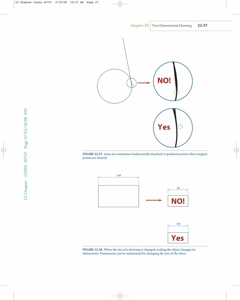
Not Really TangentThe example in Figure 22.57 shows a line that is apparently tangent to an arc. However,a closer look shows that the line is not attached to the arc at its tangent point, butrather at one of the quadrant points. This error usually occurs when the Object Snapoption is active and is set to snap to the quadrant point and tangent points. When thisis the case, the attaching entity attaches to the closest acceptable option, which maynot be the intended point. To avoid this error, whenever multiple acceptable snappossibilities exist, make sure you activate only the Snap option you want.
Improper ScalingIn an attempt to fit and print a drawing on a particular sized sheet, inexperienced 2-D CADusers sometimes decrease (or increase) the size of all of the entities on the drawingusing a Scale command. This operation does change the size of the entities; it alsochanges the dimensions attached to those entities, yielding undesired dimensionvalues as shown in Figure 22.58. To avoid this error, create all entities on a drawing totheir correct size and print on the desired sheet size by adjusting the scale of theprinting, not the scale of the drawing.
22-36 sectionfive Advanced Topics in Engineering Graphics22 C
hapter CXXXX 40757 Page 36
03/18/08 MD
NO!
Yes
FIGURE 22.56. Entities that appear connected may, under magnification, actually overlap.
22 Chapter Cxxxx 40757 3/19/08 10:37 AM Page 36
chapter 22 Two-Dimensional Drawing 22-3722
Cha
pter
C
XXXX
407
57
Page
37
03/1
8/08
MD
NO!
Yes
FIGURE 22.57. Lines are sometimes inadvertently attached to quadrant points when tangentpoints are desired.
1.00
.50
1.00
NO!
YesFIGURE 22.58. When the size of a drawing is changed, scaling the object changes itsdimensions. Dimensions can be maintained by changing the size of the sheet.
22 Chapter Cxxxx 40757 3/19/08 10:37 AM Page 37
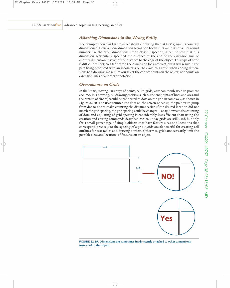
Attaching Dimensions to the Wrong EntityThe example shown in Figure 22.59 shows a drawing that, at first glance, is correctlydimensioned. However, one dimension seems odd because its value is not a nice roundnumber like the other dimensions. Upon closer inspection, it can be seen that thisdimension accidentally specified the distance to the end of the extension line ofanother dimension instead of the distance to the edge of the object. This type of erroris difficult to spot; to a fabricator, the dimension looks correct, but it will result in thepart being produced with an incorrect size. To avoid this error, when adding dimen-sions to a drawing, make sure you select the correct points on the object, not points onextension lines or another annotation.
Overreliance on GridsIn the 1980s, rectangular arrays of points, called grids, were commonly used to promoteaccuracy in a drawing. All drawing entities (such as the endpoints of lines and arcs andthe centers of circles) would be connected to dots on the grid in some way, as shown inFigure 22.60. The user counted the dots on the screen or set up the pointer to jumpfrom dot to dot to make counting the distance easier. If the desired location did notmatch the grid spacing, the grid spacing could be changed. Today, however, the countingof dots and adjusting of grid spacing is considerably less efficient than using thecreation and editing commands described earlier. Today grids are still used, but onlyfor a small percentage of simple objects that have feature sizes and locations thatcorrespond precisely to the spacing of a grid. Grids are also useful for creating celloutlines for text tables and drawing borders. Otherwise, grids unnecessarily limit thepossible sizes and locations of features on an object.
22-38 sectionfive Advanced Topics in Engineering Graphics22 C
hapter CXXXX 40757 Page 38
03/18/08 MD
2.00
1.06
NO!
Yes
FIGURE 22.59. Dimensions are sometimes inadvertently attached to other dimensionsinstead of to the object.
22 Chapter Cxxxx 40757 3/19/08 10:37 AM Page 38
Grid Accidentally Turned OnWhen a grid option is available, it can be inadvertently activated even if the grid is notvisible. When this happens, entities can snap to the grid points in the same mannerthey snap to objects. Errors occur when a user, in an attempt to snap to an entity, acci-dentally snaps to a point on the grid. To avoid these errors, make sure the grid is inac-tive if it is not needed.
Chapter SummaryThis chapter presented the basics of 2-D drawing. It was not intended to be a compre-hensive tutor on this topic. Instead, only the basic information needed to understandthe process of creating a 2-D drawing was presented. The instruments used for manualdrawing creation were shown and described, with a quick example of how they are used.Different types of geometry require the use of different instruments. These instru-ments must be used properly if accuracy and precision are to be maintained. Manualdrawing creation is prone to errors in precision because their creation is dependent onthe skill of the person making the drawing. The use of CAD improves the efficiencywith which drawings can be created, and also dramatically improves their accuracy andprecision because these are much less dependent on the skill of the operator. However,the basic CAD commands and their proper use must be mastered. In this chapter, thebasic commands found in most 2-D CAD software were described, with examples ofhow they are typically used. Most CAD software includes many more commands inaddition to these basic commands. Mastery of specific software comes only with its useand practice.
chapter 22 Two-Dimensional Drawing 22-3922
Cha
pter
C
XXXX
407
57
Page
39
03/1
8/08
MD
FIGURE 22.60. Grids are handy for creating data and information tables, but they canunnecessarily limit creativity and optimal sizes for a design.
22.07
2-D CAD: Two-dimensional computer aided design.Computer software used for the creation of two-dimensional art and text in engineering drawings.creation commands: User input in 2-D CAD softwarethat creates annotations and entities used on a drawing.
dimensions: Annotations that indicate the size, loca-tion, or orientation of the features on an object; they areused for fabrication of the object. The process of addingnotation to indicate the size, location, or orientation offeatures on an object.
22.08 glossary of key terms
22 Chapter Cxxxx 40757 3/19/08 10:25 AM Page 39
22-40 sectionfive Advanced Topics in Engineering Graphics
drafting: The process of creating an engineering draw-ing using manual techniques and tools.drafting instruments: Tools such as triangles, pencils,T squares, erasers, and compasses used to aid users increating drawings.drawings: Collections of images and annotations con-taining sufficient information for places and things to bere-created. The process of creating an engineering drawing.
editing commands: User input in 2-D CAD softwarethat edits annotations and entities used on a drawing.setup commands: User input in 2-D CAD softwarethat helps create the overall process and interface environment.snapping: Forcing the location of a point to particularlocation on a grid or an entity as that point approachesthe location.
22.08 glossary of key terms (continued)
22 Chapter C
XXXX 40757 Page 4003/18/08 M
D
1. What is the purpose of different lead hardnesses inthe creation of manual drawings?
2. How can 30-60 and 45 triangles be used to createangles other than 30°, 45°, 60°, and 90°?
3. How is the circle template used to create roundededges?
4. When should a circle instead of a compass be used tocreate a circle?
5. What is the purpose of the eraser shield?
6. What are some similarities between manual draftingand 2-D CAD?
7. What are some difference between manual draftingand 2-D CAD?
8. In the creation of drawings, what are some advan-tages of drawing them manually compared to using2-D CAD software?
9. In the creation of drawings, what are some advan-tages of drawing them manually compared to using2-D CAD software?
10. What is the purpose of the Object Snap command in2-D CAD?
11. How are layers used in 2-D CAD?
22.09 questions for review
22 Chapter Cxxxx 40757 3/19/08 10:25 AM Page 40
chapter 22 Two-Dimensional Drawing 22-41
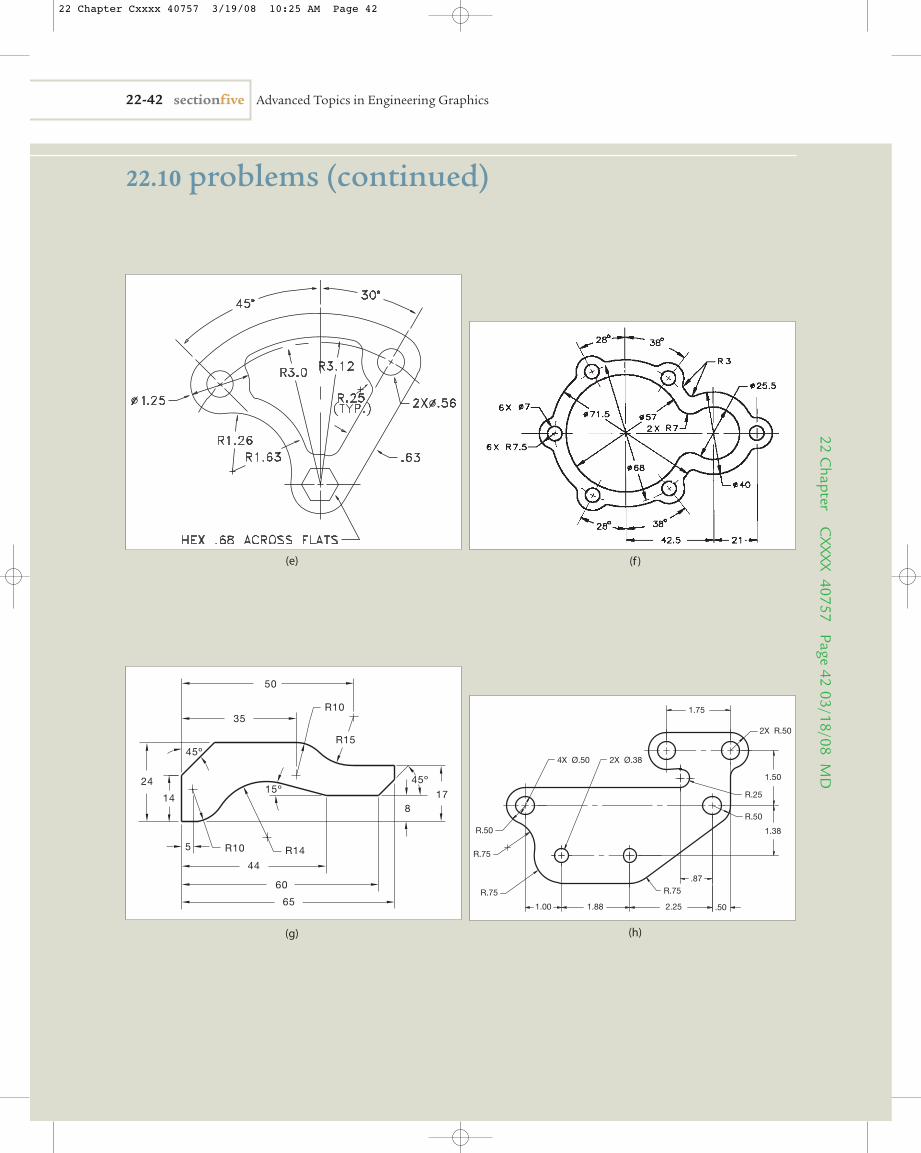
1. Reproduce the geometric patterns using either manual drawing instruments or 2-D CAD as directed by yourinstructor.
22.10 problems
22 C
hapt
er
CXX
XX 4
0757
Pa
ge 4
103
/18/
08 M
D
(a)
(d)
(b)
(c)
22 Chapter Cxxxx 40757 3/19/08 10:25 AM Page 41
22-42 sectionfive Advanced Topics in Engineering Graphics22 C
hapter CXXXX 40757 Page 42
03/18/08 MD
(f )
R.75
R.50
R.75 R.75
1.00 1.88 2.25 .50
.87
4X Ø.50 2X Ø.38
1.50
1.38
R.50
R.25
2X R.50
1.75
(h)
R10 R14
15º
R15
14
24
5
44
60
817
35
50
R10
65
45º
45º
(g)
22.10 problems (continued)
(e)
22 Chapter Cxxxx 40757 3/19/08 10:25 AM Page 42
chapter 22 Two-Dimensional Drawing 22-43
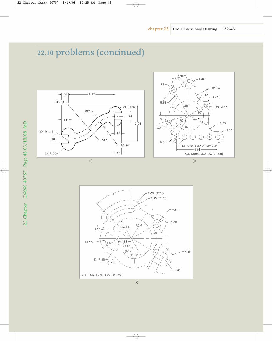
22.10 problems (continued)
22 C
hapt
er
CXX
XX 4
0757
Pa
ge 4
303
/18/
08 M
D
(j)
(k)
2X R.60
2X R.55
.375
.375
.65
.64
.62 4.12
.58
R3.00
R2.25
.63
.76
3.24
2X R1.18
(i)
22 Chapter Cxxxx 40757 3/19/08 10:25 AM Page 43
22-44 sectionfive Advanced Topics in Engineering Graphics22 C
hapter CXXXX 40757 Page 44
03/18/08 MD
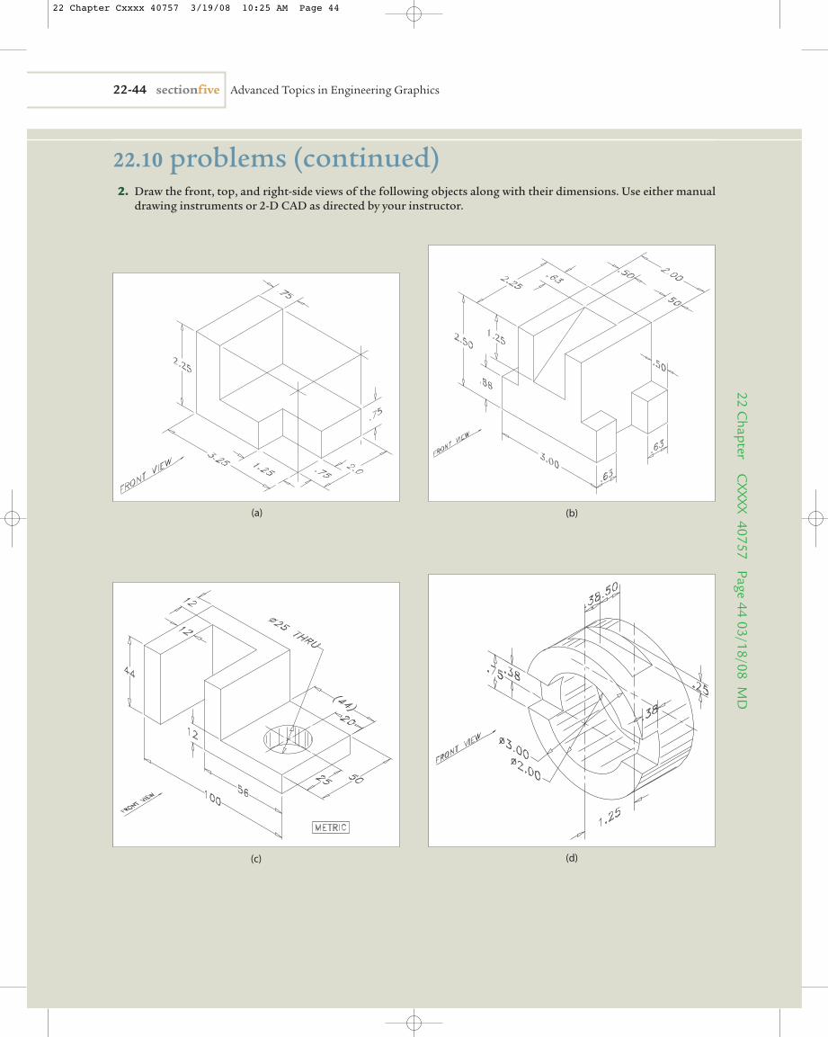
(a) (b)
22.10 problems (continued)2. Draw the front, top, and right-side views of the following objects along with their dimensions. Use either manual
drawing instruments or 2-D CAD as directed by your instructor.
(c) (d)
22 Chapter Cxxxx 40757 3/19/08 10:25 AM Page 44
chapter 22 Two-Dimensional Drawing 22-4522
Cha
pter
C
XXXX
407
57
Page
45
03/1
8/08
MD
22.10 problems (continued)
(e) (f )
(g) (h)
22 Chapter Cxxxx 40757 3/19/08 10:25 AM Page 45
22-46 sectionfive Advanced Topics in Engineering Graphics22 C