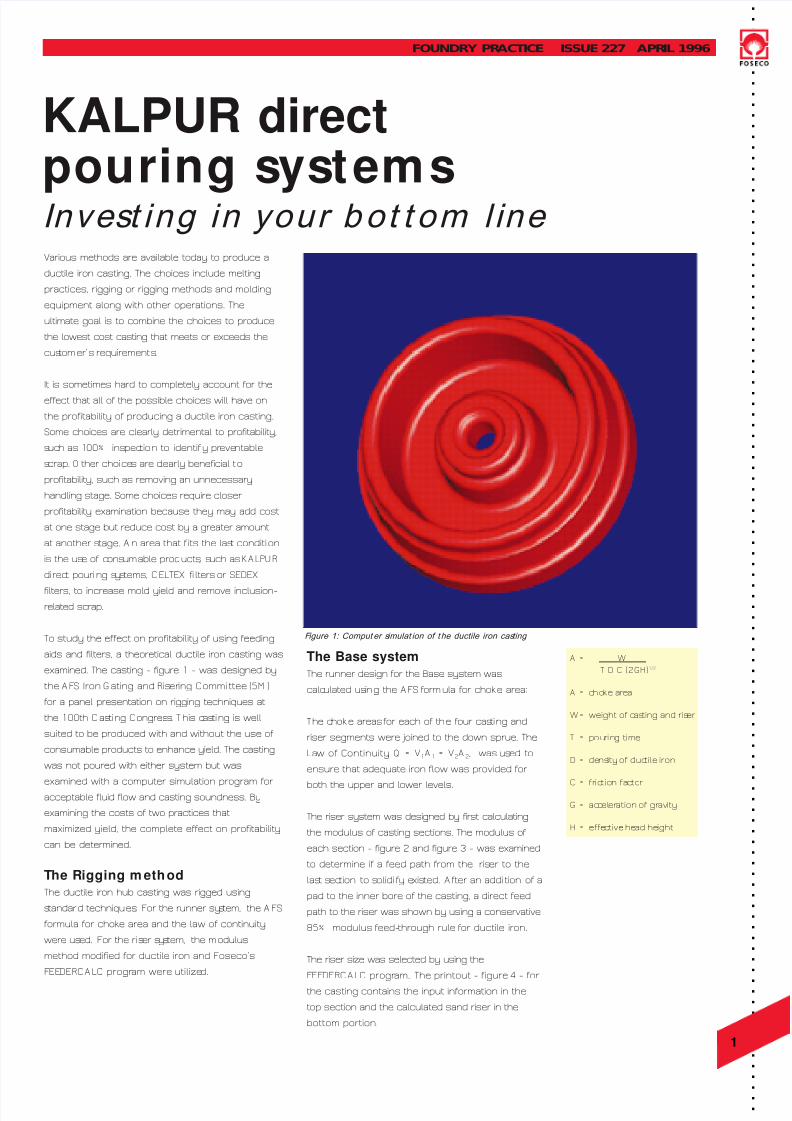
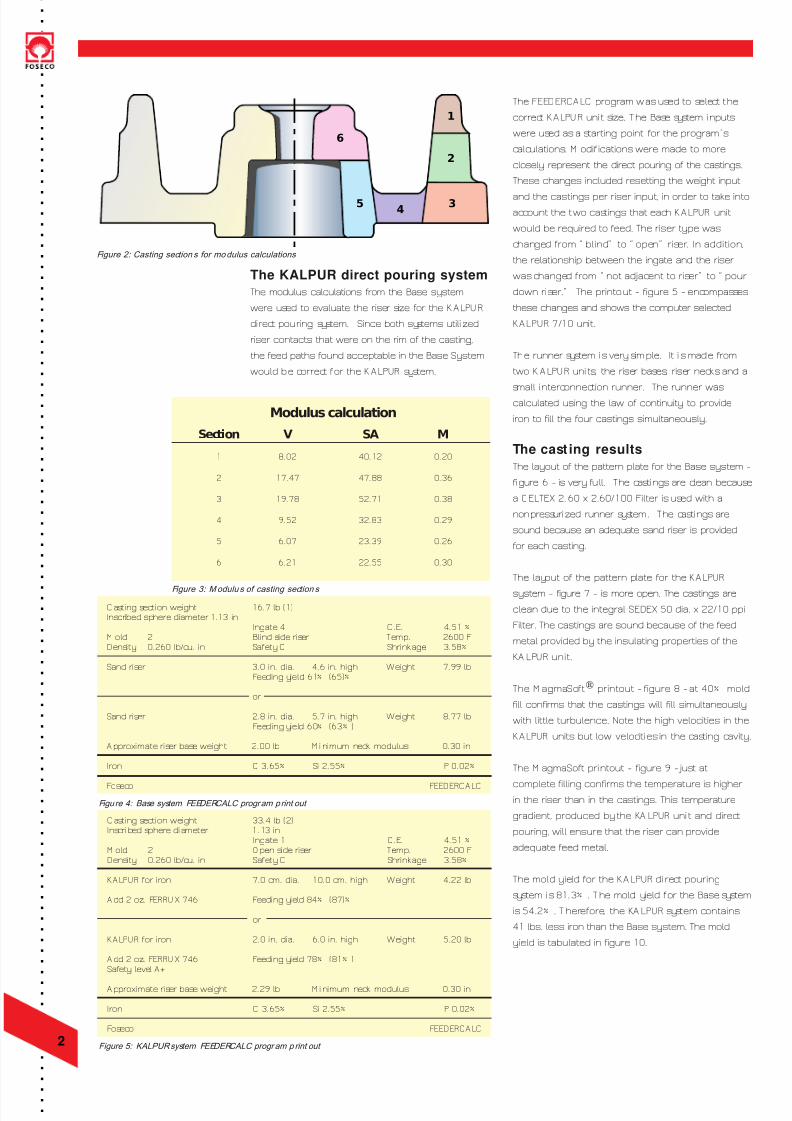
. . . . . . . . . . . . . . . . . . . . . . . . . . . . . . . . . . . . . . . . . . . . . . . . . . . . . . . . . . . . . . . . . . . . . . . . . . . . . . . . . . . . . . . . . . . . . . . . . . . . . . . . 1 FOUNDRY PR ACTICE ISSUE 227 APR IL 1996 KALPUR direct pou rin g s ys tems I nves t ing in your b ot t om li ne Various methods are available today to produce a ductile iron casting. The choices include melting practices, rigging or rigging methods and molding equipment along with other operations. The ultimate goal is to combine the choices to produce the lowest cost casting that meets or exceeds the cus tomer’ s requirement s . It is sometimes hard to completely account for the effect that all of the possible choices will have on the profitability of producing a ductile iron casting. Some choices are clearly detrimental to profitability, s uc h as 1 00% ins pec tio n to identif y preventable s crap. O ther choi ce s are c learly beneficial t o profitability, such as removing an unnecessary handling stage. Some choices require closer profitability examination because they may add cost at one stage but reduce cost by a greater amount at another s tage. A n area that f its the las t conditi on is the us e of c ons umable products, s uch as K A LPU R di rec t pouri ng s y stems, C ELTEX filters or SEDEX filters, to increase mold yield and remove inclusion- related scrap. To study the effect on profitability of using feeding aids and filters, a theoretical ductile iron casting was examined. The casting - figure 1 - was designed by the A FS Iron Gating and Riser ing C ommi ttee (5M ) for a panel presentation on rigging techniques at the 100th C as ti ng C ongres s . T his c as ti ng is well suited to be produced with and without the use ofconsumable products to enhance yield. The casting was not poured with either system but was examined with a computer simulation program for acceptable fluid flow and casting soundness. By examining the costs of two practices that maximized yield, the complete effect on profitability can be determined. The Rigging method The ductile iron hub casting was rigged using s tandar d techniques . For the runner sy s tem, the A FS formula for choke area and the law of continuity were us ed. For the riser s y s tem, the modulus method modified for ductile iron and Foseco‘s F EE DERC A LC progr am were utilize d. The Base system The runner design for the Base system was calc ulated using the A FS form ula for chok e area: T he c hok e areas for each of the four cas ti ng and riser segments were joined to the down sprue. The La w of Continuity , Q = V 1 A 1 = V 2 A 2 , was us ed to ensure that adequate iron flow was provided for both the upper and lower levels. The riser system was designed by first calculating the modulus of casting sections. The modulus ofeach section - figure 2 and figure 3 - was examined to determine if a feed path from the ris er to the las t s ection to s olidi fy e xisted. A fter an addi tion of a pad to the inner bore of the casting, a direct feed path to the riser was shown by using a conservative 85% modulus feed-through rule for ductile iron. The riser size was selected by using the F EE DERC A LC progr am. The printout - figure 4 - for the casting contains the input information in the top section and the calculated sand riser in the bottom portion. A = W T D C (2GH) 1/2 A = cho ke area W= weight of c as ting and ris er T = pou ring ti me D = dens ity of duc tile iron C = friction fa c tor G= ac celeration of gr avity H = effe c tive he ad he ight F igure 1: Comput er s imulat ion of t he ductile iron cas ting
Transcript
7/28/2019 227-01 KALPUR Invest in Your Botton Line