2.3 Dimensional drawings In this chapter you can find the dimensions of the geared motors. There is a dimensional drawing for every possible shaft/housing design, each with the tables for gear unit di- mensions, motor dimensions and geared motor dimensions. Dimensions can exceed the specifications of ISO 2768-mK due to casting tolerances or accumulation of indi- vidual tolerances. We reserve the right to make dimensional changes due to ongoing technical development. You can download CAD models of our standard drives at http://cad.stoeber.de . Combination options and the dimensions of forced ventilated geared motors can be found at http:// cad.stoeber.de . Tolerances Solid shaft Tolerance Shaft ∅ fit ≤ 50 mm DIN 748-1, ISO k6 Shaft ∅ fit > 50 mm DIN 748-1, ISO m6 Feather keys DIN 6885-1, high form A Balance quality Q 2.5 (balanced with half feather key) Centering holes in solid shafts in accordance with DIN 332-2, DR shape Thread size M4 M5 M6 M8 M10 M12 M16 M20 M24 Thread depth [mm] 10 12.5 16 19 22 28 36 42 50 2 P planetary geared motors 2.3 Dimensional drawings 31
Transcript
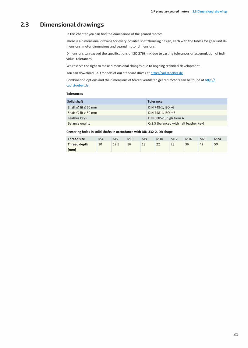
2.3 Dimensional drawingsIn this chapter you can find the dimensions of the geared motors.
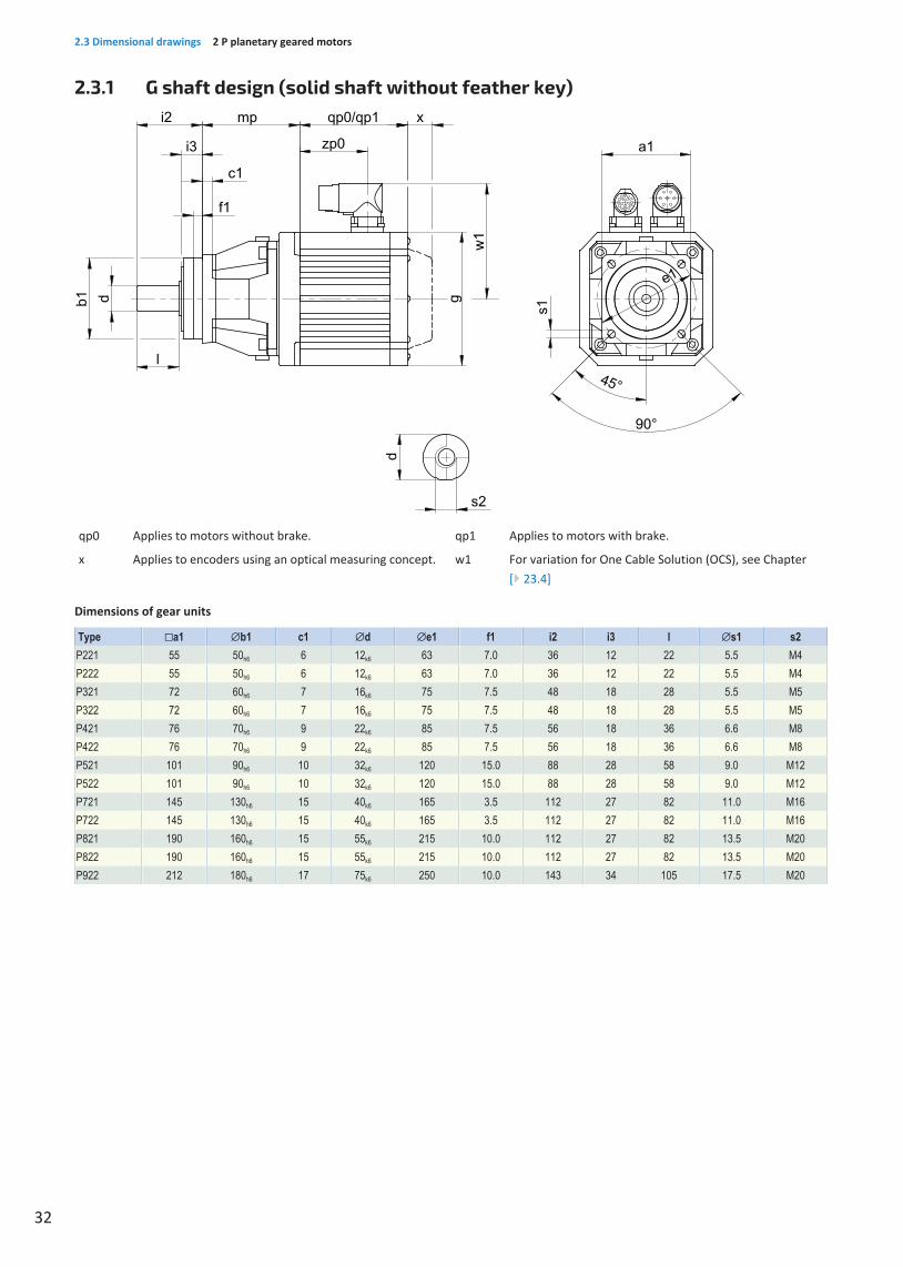
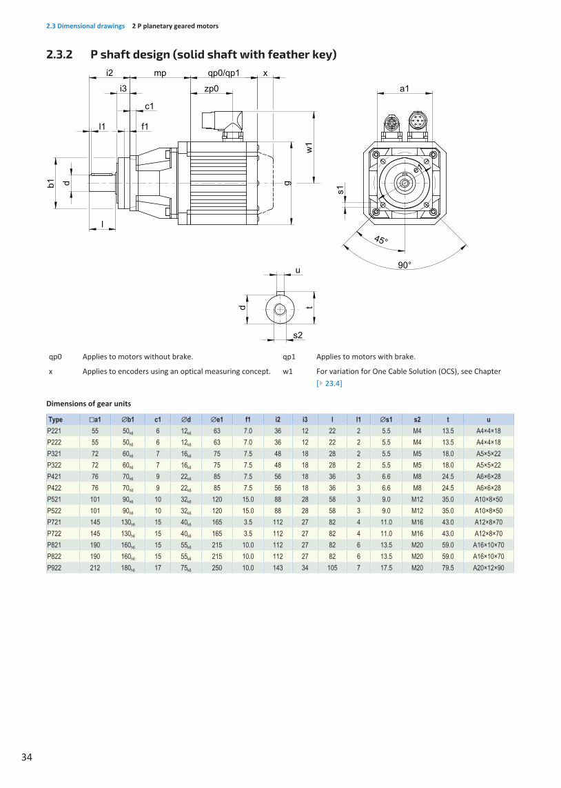
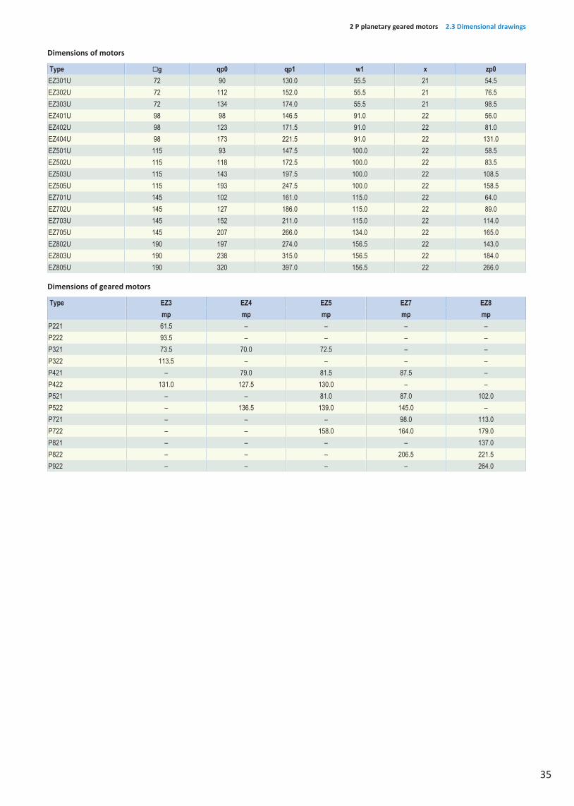
There is a dimensional drawing for every possible shaft/housing design, each with the tables for gear unit di-mensions, motor dimensions and geared motor dimensions.
Dimensions can exceed the specifications of ISO 2768-mK due to casting tolerances or accumulation of indi-vidual tolerances.
We reserve the right to make dimensional changes due to ongoing technical development.
You can download CAD models of our standard drives at http://cad.stoeber.de.
Combination options and the dimensions of forced ventilated geared motors can be found at http://cad.stoeber.de.
Tolerances
Solid shaft Tolerance
Shaft ∅ fit ≤ 50 mm DIN 748-1, ISO k6Shaft ∅ fit > 50 mm DIN 748-1, ISO m6Feather keys DIN 6885-1, high form ABalance quality Q 2.5 (balanced with half feather key)
Centering holes in solid shafts in accordance with DIN 332-2, DR shape
2 P planetary geared motors 2.3 Dimensional drawings
35
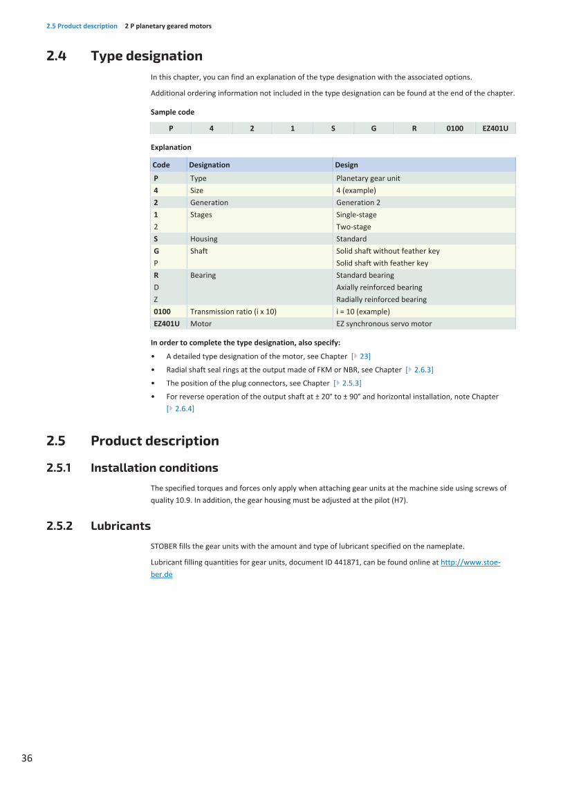
2.4 Type designationIn this chapter, you can find an explanation of the type designation with the associated options.
Additional ordering information not included in the type designation can be found at the end of the chapter.
Sample code
P 4 2 1 S G R 0100 EZ401U
Explanation
Code Designation Design
P Type Planetary gear unit4 Size 4 (example)2 Generation Generation 212
Stages Single-stageTwo-stage
S Housing StandardGP
Shaft Solid shaft without feather keySolid shaft with feather key
RDZ
Bearing Standard bearingAxially reinforced bearingRadially reinforced bearing
0100 Transmission ratio (i x 10) i = 10 (example)EZ401U Motor EZ synchronous servo motor
In order to complete the type designation, also specify:
• A detailed type designation of the motor, see Chapter [} 23]
• Radial shaft seal rings at the output made of FKM or NBR, see Chapter [} 2.6.3]
• The position of the plug connectors, see Chapter [} 2.5.3]
• For reverse operation of the output shaft at ± 20° to ± 90° and horizontal installation, note Chapter [} 2.6.4]
2.5 Product description
2.5.1 Installation conditions
The specified torques and forces only apply when attaching gear units at the machine side using screws ofquality 10.9. In addition, the gear housing must be adjusted at the pilot (H7).
2.5.2 Lubricants
STOBER fills the gear units with the amount and type of lubricant specified on the nameplate.
Lubricant filling quantities for gear units, document ID 441871, can be found online at http://www.stoe-ber.de
2.5 Product description 2 P planetary geared motors
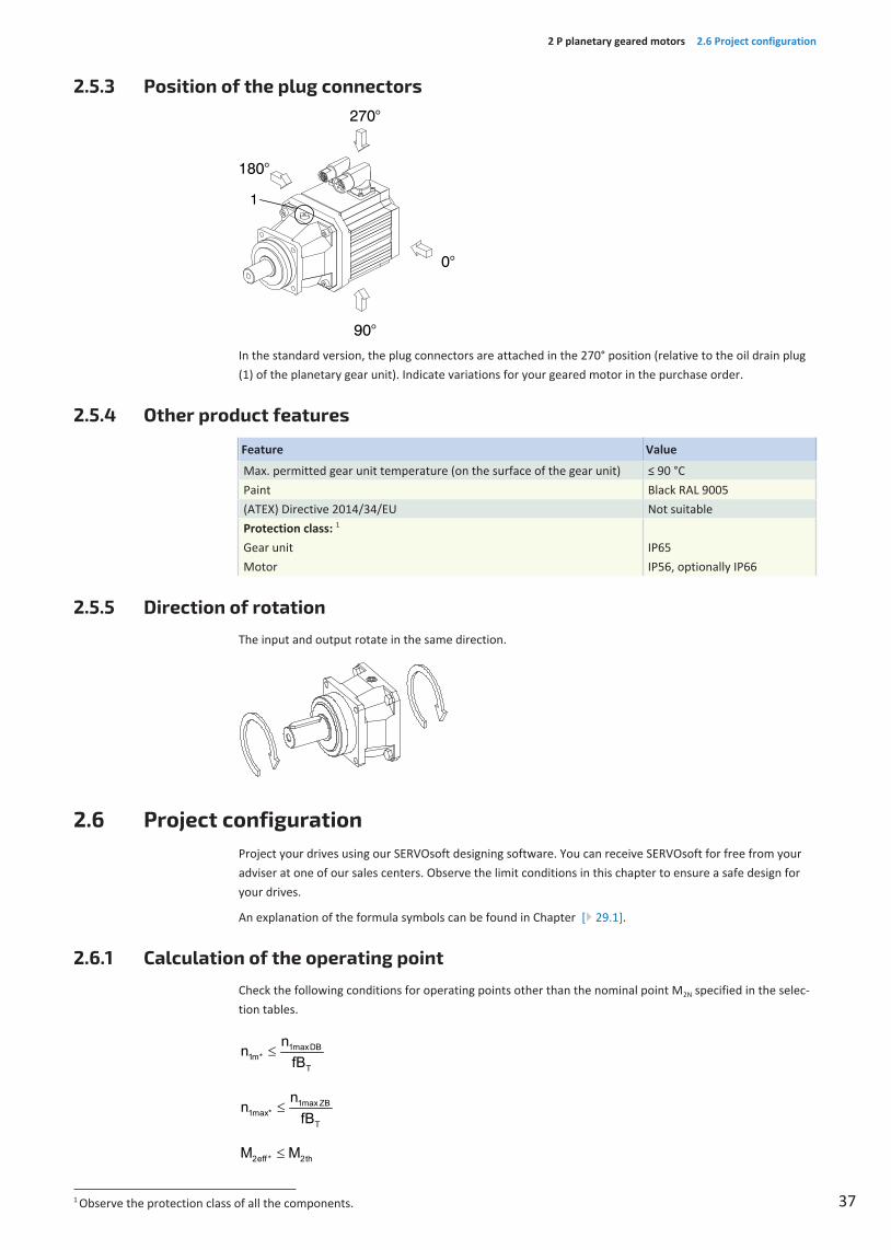
In the standard version, the plug connectors are attached in the 270° position (relative to the oil drain plug(1) of the planetary gear unit). Indicate variations for your geared motor in the purchase order.
2.5.4 Other product features
Feature Value
Max. permitted gear unit temperature (on the surface of the gear unit) ≤ 90 °CPaint Black RAL 9005(ATEX) Directive 2014/34/EU Not suitableProtection class: 1
Gear unitMotor
IP65IP56, optionally IP66
2.5.5 Direction of rotation
The input and output rotate in the same direction.
2.6 Project configurationProject your drives using our SERVOsoft designing software. You can receive SERVOsoft for free from youradviser at one of our sales centers. Observe the limit conditions in this chapter to ensure a safe design foryour drives.
An explanation of the formula symbols can be found in Chapter [} 29.1].
2.6.1 Calculation of the operating point
Check the following conditions for operating points other than the nominal point M2N specified in the selec-tion tables.
1maxDB1m*
T
nnfB
£
1maxZB1max*
T
nnfB
£
2eff * 2thM M£
1 Observe the protection class of all the components.
2 P planetary geared motors 2.6 Project configuration
37
2acc* 2accM M£
2NOT* 2NOTM M£
2eq* 2Nop t
SM MfB fB
£ ××
The values for n1maxDB, n1maxZB, M2acc, M2NOT, M2N and S can be found in the selection tables.
The values for fBT, fBop and fBt can be found in the corresponding tables in this chapter.
Calculate the thermal limit torque M2th for a duty cycle > 50%.
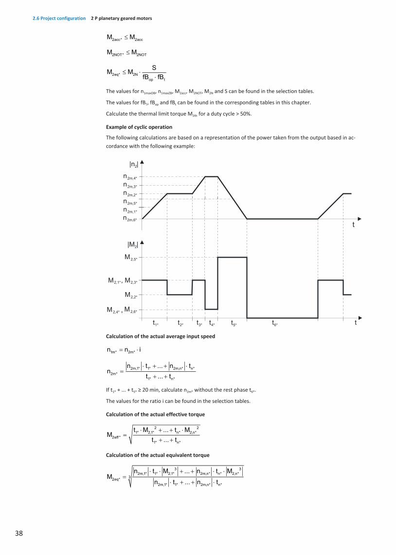
Example of cyclic operation
The following calculations are based on a representation of the power taken from the output based in ac-cordance with the following example:
Calculation of the actual average input speed
1m* 2m*n n i= ×
2m,1* 1* 2m,n* n*2m*
1* n*
n t ... n tn
t ... t× + + ×
=+ +
If t1* + ... + t5* ≥ 20 min, calculate n2m* without the rest phase t6*.
The values for the ratio i can be found in the selection tables.
Calculation of the actual effective torque
2 21* 2,1* n* 2,n*
2eff *1* n*
t M ... t MM
t ... t× + + ×
=+ +
Calculation of the actual equivalent torque
3 32m,1* 1* 2,1* 2m,n* n* 2,n*
32eq*2m,1* 1* 2m,n* n*
n t M ... n t MM
n t ... n t
× × + + × ×=
× + + ×
2.6 Project configuration 2 P planetary geared motors
38
Calculation of the thermal limit torque
Calculate the thermal limit torque M2th for a duty cycle ED20 > 50% and the actual average input speed n1m*.(At Kmot,th ≤ 0 you must reduce the average input speed n1m* accordingly or select another geared motor size.)
2th op mot,thM M i K= × ×
3th 1m*
mot,th Ta nK 0,95 fB1000 1000
æ ö= - × × ç ÷è ø
The values for i and ath can be found in the selection tables.
The values for fBT can be found in the corresponding table in this chapter.
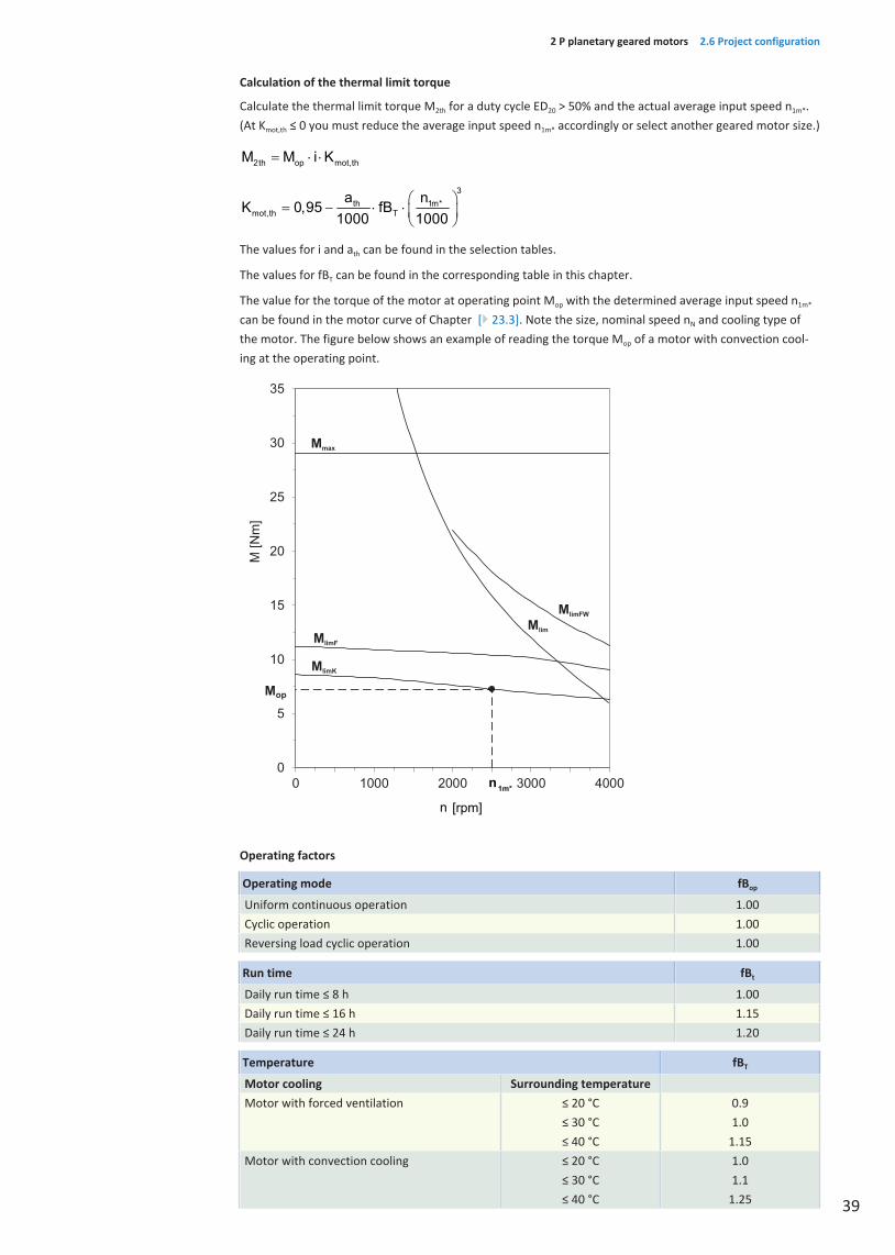
The value for the torque of the motor at operating point Mop with the determined average input speed n1m*
can be found in the motor curve of Chapter [} 23.3]. Note the size, nominal speed nN and cooling type ofthe motor. The figure below shows an example of reading the torque Mop of a motor with convection cool-ing at the operating point.
Daily run time ≤ 8 h 1.00Daily run time ≤ 16 h 1.15Daily run time ≤ 24 h 1.20
Temperature fBT
Motor cooling Surrounding temperatureMotor with forced ventilation ≤ 20 °C
≤ 30 °C≤ 40 °C
0.91.0
1.15Motor with convection cooling ≤ 20 °C
≤ 30 °C≤ 40 °C
1.01.1
1.25
2 P planetary geared motors 2.6 Project configuration
39
Notes
• The maximum permitted gear unit temperature (see the "Other product features" chapter) must not beexceeded. Doing so may result in damage to the geared motor.
• For braking from full speed (for example when the power fails or when setting up the machine), notethe permitted gear unit torques (M2acc, M2NOT) in the selection tables.
• The values specified in the selection tables for M2acc refer to the gear units with a solid shaft designwithout feather key (G). We recommend this shaft design in general for cyclic operation.
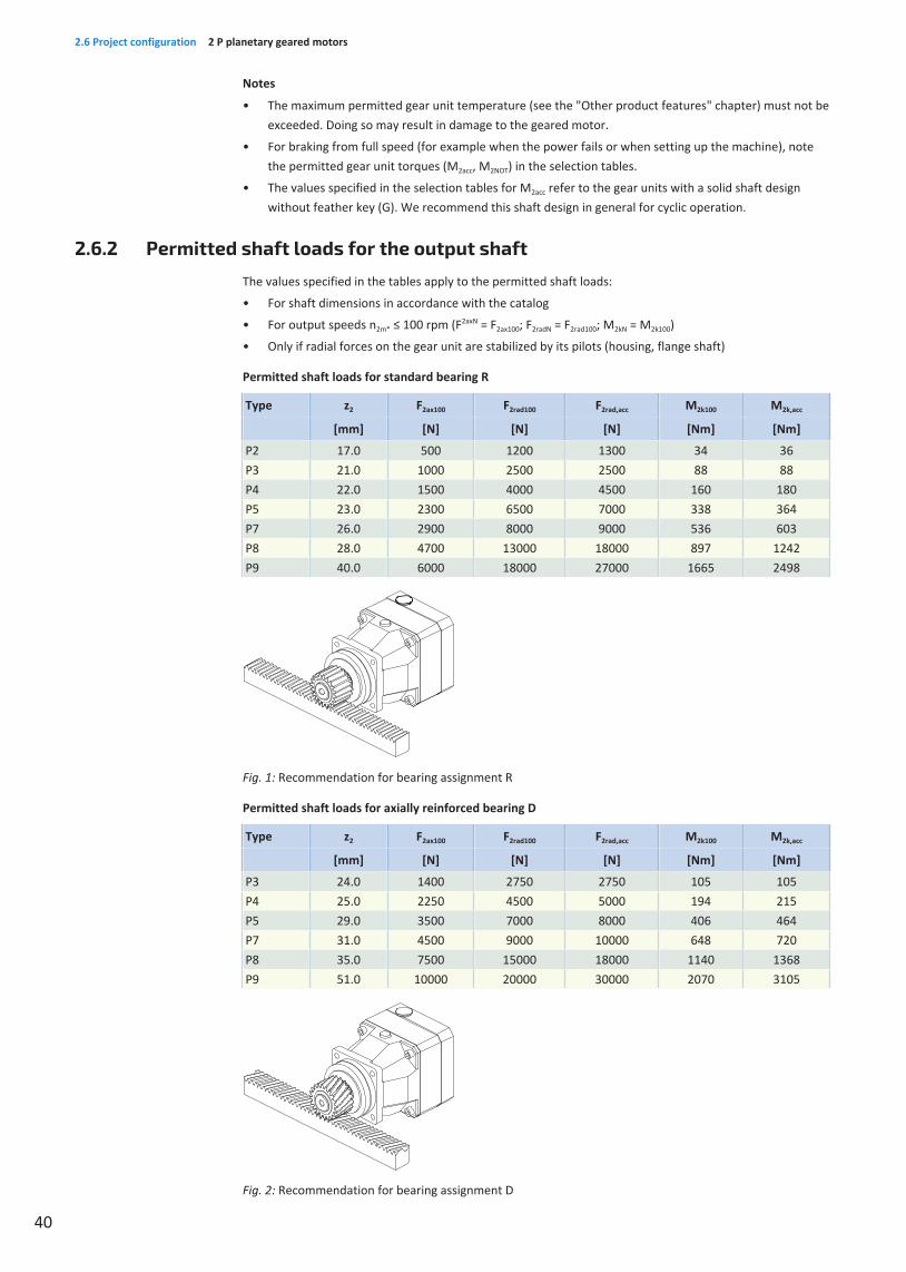
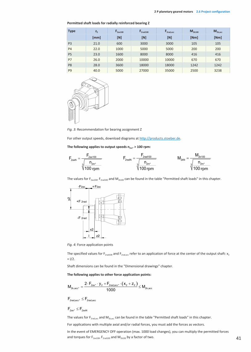
2.6.2 Permitted shaft loads for the output shaft
The values specified in the tables apply to the permitted shaft loads:
• For shaft dimensions in accordance with the catalog
For other output speeds, download diagrams at http://products.stoeber.de.
The following applies to output speeds n2m* > 100 rpm:
2ax1002axN
2m*31
FFn
100min-
=
rpm
2rad1002radN
2m*31
FFn
100min-
=
rpm
2k1002kN
2m*31
MMn
100min-
=
rpm
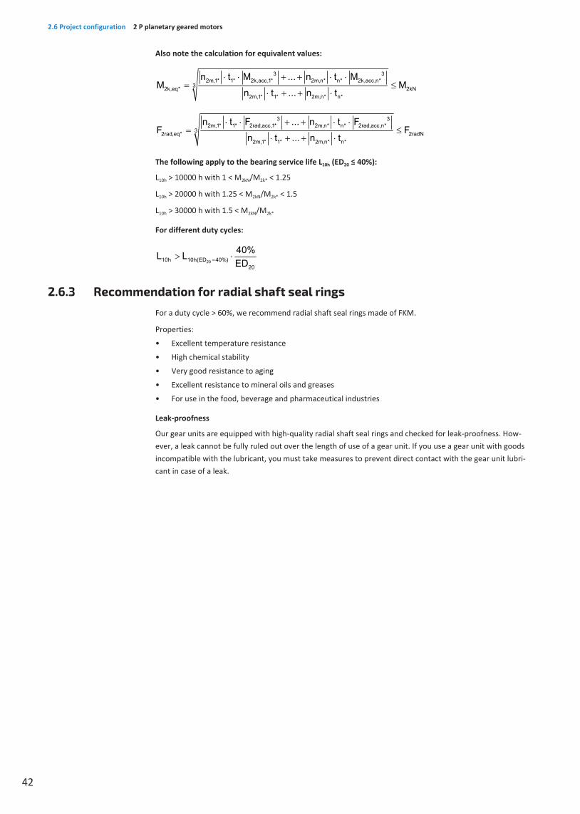
The values for F2ax100, F2rad100 and M2k100 can be found in the table "Permitted shaft loads" in this chapter.
Fig. 4: Force application points
The specified values for F2rad100 and F2rad,acc refer to an application of force at the center of the output shaft: x2
= l/2.
Shaft dimensions can be found in the "Dimensional drawings" chapter.
The following applies to other force application points:
( )2ax* 2 2rad,acc* 2 22k,acc* 2k,acc
2 F y F x zM M
1000× × + × +
= £
2rad,acc* 2rad,accF F£
2ax* 2axNF F£
The values for F2rad,acc and M2k,acc can be found in the table "Permitted shaft loads" in this chapter.
For applications with multiple axial and/or radial forces, you must add the forces as vectors.
In the event of EMERGENCY OFF operation (max. 1000 load changes), you can multiply the permitted forcesand torques for F2ax100, F2rad100 and M2k100 by a factor of two.
2 P planetary geared motors 2.6 Project configuration
The following apply to the bearing service life L10h (ED20 ≤ 40%):
L10h > 10000 h with 1 < M2kN/M2k* < 1.25
L10h > 20000 h with 1.25 < M2kN/M2k* < 1.5
L10h > 30000 h with 1.5 < M2kN/M2k*
For different duty cycles:
2010h 10h(ED 40%)20
40%L LED=> ×
2.6.3 Recommendation for radial shaft seal rings
For a duty cycle > 60%, we recommend radial shaft seal rings made of FKM.
Properties:
• Excellent temperature resistance
• High chemical stability
• Very good resistance to aging
• Excellent resistance to mineral oils and greases
• For use in the food, beverage and pharmaceutical industries
Leak-proofness
Our gear units are equipped with high-quality radial shaft seal rings and checked for leak-proofness. How-ever, a leak cannot be fully ruled out over the length of use of a gear unit. If you use a gear unit with goodsincompatible with the lubricant, you must take measures to prevent direct contact with the gear unit lubri-cant in case of a leak.
2.6 Project configuration 2 P planetary geared motors
42
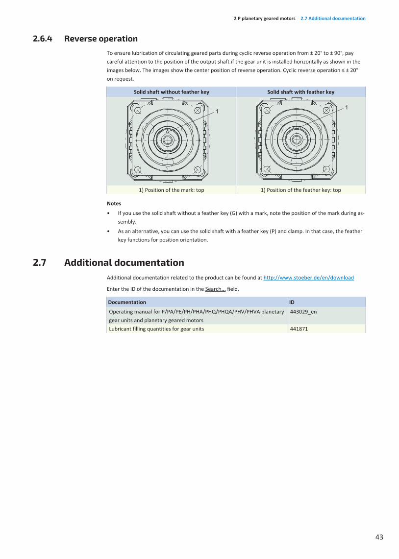
2.6.4 Reverse operation
To ensure lubrication of circulating geared parts during cyclic reverse operation from ± 20° to ± 90°, paycareful attention to the position of the output shaft if the gear unit is installed horizontally as shown in theimages below. The images show the center position of reverse operation. Cyclic reverse operation ≤ ± 20°on request.
Solid shaft without feather key Solid shaft with feather key
11
1) Position of the mark: top 1) Position of the feather key: top
Notes
• If you use the solid shaft without a feather key (G) with a mark, note the position of the mark during as-sembly.
• As an alternative, you can use the solid shaft with a feather key (P) and clamp. In that case, the featherkey functions for position orientation.
2.7 Additional documentationAdditional documentation related to the product can be found at http://www.stoeber.de/en/download
Enter the ID of the documentation in the Search... field.
Documentation ID
Operating manual for P/PA/PE/PH/PHA/PHQ/PHQA/PHV/PHVA planetarygear units and planetary geared motors
443029_en
Lubricant filling quantities for gear units 441871
2 P planetary geared motors 2.7 Additional documentation
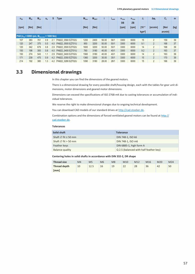
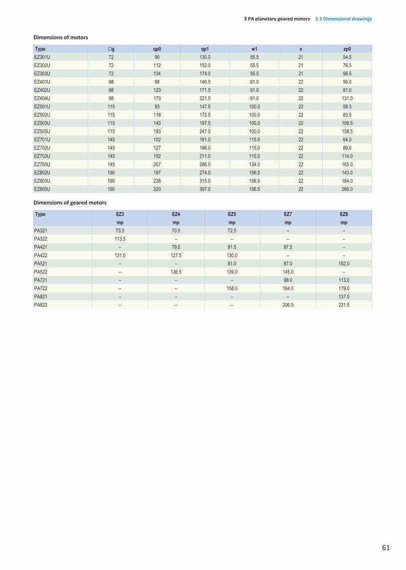
3.3 Dimensional drawingsIn this chapter you can find the dimensions of the geared motors.
There is a dimensional drawing for every possible shaft/housing design, each with the tables for gear unit di-mensions, motor dimensions and geared motor dimensions.
Dimensions can exceed the specifications of ISO 2768-mK due to casting tolerances or accumulation of indi-vidual tolerances.
We reserve the right to make dimensional changes due to ongoing technical development.
You can download CAD models of our standard drives at http://cad.stoeber.de.
Combination options and the dimensions of forced ventilated geared motors can be found at http://cad.stoeber.de.
Tolerances
Solid shaft Tolerance
Shaft ∅ fit ≤ 50 mm DIN 748-1, ISO k6Shaft ∅ fit > 50 mm DIN 748-1, ISO m6Feather keys DIN 6885-1, high form ABalance quality Q 2.5 (balanced with half feather key)
Centering holes in solid shafts in accordance with DIN 332-2, DR shape
3 PA planetary geared motors 3.3 Dimensional drawings
61
3.4 Type designationIn this chapter, you can find an explanation of the type designation with the associated options.
Additional ordering information not included in the type designation can be found at the end of the chapter.
Sample code
PA 4 2 2 S G D 0200 EZ401U
Explanation
Code Designation Design
PA Type Low-backlash planetary gear unit4 Size 4 (example)2 Generation Generation 212
Stages Single-stageTwo-stage
S Housing StandardGP
Shaft Solid shaft without feather keySolid shaft with feather key
D Bearing Axially reinforced bearing0200 Transmission ratio (i x 10) i = 20 (example)EZ401U Motor EZ synchronous servo motor
In order to complete the type designation, also specify:
• A detailed type designation of the motor, see Chapter [} 23]
• The position of the plug connectors, see Chapter [} 3.5.3]
• For reverse operation of the output shaft at ± 20° to ± 90° and horizontal installation, note Chapter [} 3.6.4]
3.5 Product description
3.5.1 Installation conditions
The specified torques and forces only apply when attaching gear units at the machine side using screws ofquality 10.9. In addition, the gear housing must be adjusted at the pilot (H7).
3.5.2 Lubricants
STOBER fills the gear units with the amount and type of lubricant specified on the nameplate.
Lubricant filling quantities for gear units, document ID 441871, can be found online at http://www.stoe-ber.de
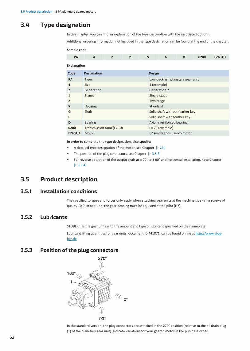
3.5.3 Position of the plug connectors
In the standard version, the plug connectors are attached in the 270° position (relative to the oil drain plug(1) of the planetary gear unit). Indicate variations for your geared motor in the purchase order.
3.5 Product description 3 PA planetary geared motors
Max. permitted gear unit temperature (on the surface of the gear unit) ≤ 90 °CPaint Black RAL 9005(ATEX) Directive 2014/34/EU Not suitableProtection class: 1
Gear unitMotor
IP65IP56, optionally IP66
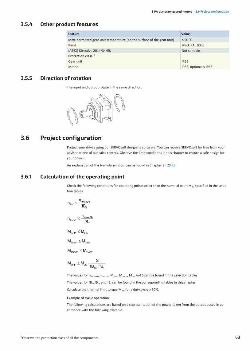
3.5.5 Direction of rotation
The input and output rotate in the same direction.
3.6 Project configurationProject your drives using our SERVOsoft designing software. You can receive SERVOsoft for free from youradviser at one of our sales centers. Observe the limit conditions in this chapter to ensure a safe design foryour drives.
An explanation of the formula symbols can be found in Chapter [} 29.1].
3.6.1 Calculation of the operating point
Check the following conditions for operating points other than the nominal point M2N specified in the selec-tion tables.
1maxDB1m*
T
nnfB
£
1maxZB1max*
T
nnfB
£
2eff * 2thM M£
2acc* 2accM M£
2NOT* 2NOTM M£
2eq* 2Nop t
SM MfB fB
£ ××
The values for n1maxDB, n1maxZB, M2acc, M2NOT, M2N and S can be found in the selection tables.
The values for fBT, fBop and fBt can be found in the corresponding tables in this chapter.
Calculate the thermal limit torque M2th for a duty cycle > 50%.
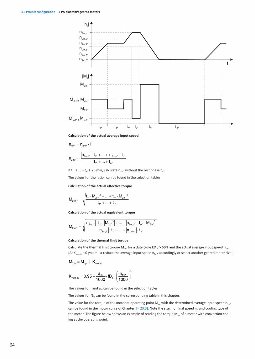
Example of cyclic operation
The following calculations are based on a representation of the power taken from the output based in ac-cordance with the following example:
1 Observe the protection class of all the components.
3 PA planetary geared motors 3.6 Project configuration
63
Calculation of the actual average input speed
1m* 2m*n n i= ×
2m,1* 1* 2m,n* n*2m*
1* n*
n t ... n tn
t ... t× + + ×
=+ +
If t1* + ... + t5* ≥ 20 min, calculate n2m* without the rest phase t6*.
The values for the ratio i can be found in the selection tables.
Calculation of the actual effective torque
2 21* 2,1* n* 2,n*
2eff *1* n*
t M ... t MM
t ... t× + + ×
=+ +
Calculation of the actual equivalent torque
3 32m,1* 1* 2,1* 2m,n* n* 2,n*
32eq*2m,1* 1* 2m,n* n*
n t M ... n t MM
n t ... n t
× × + + × ×=
× + + ×
Calculation of the thermal limit torque
Calculate the thermal limit torque M2th for a duty cycle ED20 > 50% and the actual average input speed n1m*.(At Kmot,th ≤ 0 you must reduce the average input speed n1m* accordingly or select another geared motor size.)
2th op mot,thM M i K= × ×
3th 1m*
mot,th Ta nK 0,95 fB1000 1000
æ ö= - × × ç ÷è ø
The values for i and ath can be found in the selection tables.
The values for fBT can be found in the corresponding table in this chapter.
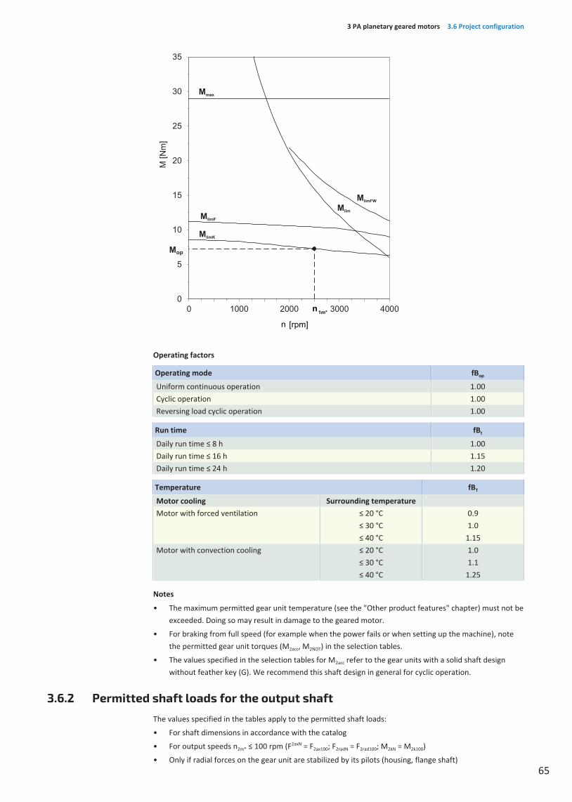
The value for the torque of the motor at operating point Mop with the determined average input speed n1m*
can be found in the motor curve of Chapter [} 23.3]. Note the size, nominal speed nN and cooling type ofthe motor. The figure below shows an example of reading the torque Mop of a motor with convection cool-ing at the operating point.
3.6 Project configuration 3 PA planetary geared motors
Daily run time ≤ 8 h 1.00Daily run time ≤ 16 h 1.15Daily run time ≤ 24 h 1.20
Temperature fBT
Motor cooling Surrounding temperatureMotor with forced ventilation ≤ 20 °C
≤ 30 °C≤ 40 °C
0.91.0
1.15Motor with convection cooling ≤ 20 °C
≤ 30 °C≤ 40 °C
1.01.1
1.25
Notes
• The maximum permitted gear unit temperature (see the "Other product features" chapter) must not beexceeded. Doing so may result in damage to the geared motor.
• For braking from full speed (for example when the power fails or when setting up the machine), notethe permitted gear unit torques (M2acc, M2NOT) in the selection tables.
• The values specified in the selection tables for M2acc refer to the gear units with a solid shaft designwithout feather key (G). We recommend this shaft design in general for cyclic operation.
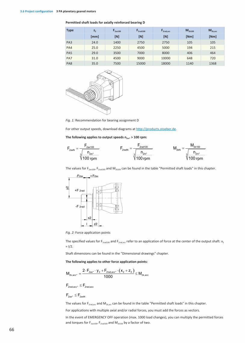
3.6.2 Permitted shaft loads for the output shaft
The values specified in the tables apply to the permitted shaft loads:
• For shaft dimensions in accordance with the catalog
For other output speeds, download diagrams at http://products.stoeber.de.
The following applies to output speeds n2m* > 100 rpm:
2ax1002axN
2m*31
FFn
100min-
=
rpm
2rad1002radN
2m*31
FFn
100min-
=
rpm
2k1002kN
2m*31
MMn
100min-
=
rpm
The values for F2ax100, F2rad100 and M2k100 can be found in the table "Permitted shaft loads" in this chapter.
Fig. 2: Force application points
The specified values for F2rad100 and F2rad,acc refer to an application of force at the center of the output shaft: x2
= l/2.
Shaft dimensions can be found in the "Dimensional drawings" chapter.
The following applies to other force application points:
( )2ax* 2 2rad,acc* 2 22k,acc* 2k,acc
2 F y F x zM M
1000× × + × +
= £
2rad,acc* 2rad,accF F£
2ax* 2axNF F£
The values for F2rad,acc and M2k,acc can be found in the table "Permitted shaft loads" in this chapter.
For applications with multiple axial and/or radial forces, you must add the forces as vectors.
In the event of EMERGENCY OFF operation (max. 1000 load changes), you can multiply the permitted forcesand torques for F2ax100, F2rad100 and M2k100 by a factor of two.
3.6 Project configuration 3 PA planetary geared motors
The following apply to the bearing service life L10h (ED20 ≤ 40%):
L10h > 10000 h with 1 < M2kN/M2k* < 1.25
L10h > 20000 h with 1.25 < M2kN/M2k* < 1.5
L10h > 30000 h with 1.5 < M2kN/M2k*
For different duty cycles:
2010h 10h(ED 40%)20
40%L LED=> ×
3.6.3 Radial shaft seal ringsLeak-proofness
Our gear units are equipped with high-quality radial shaft seal rings and checked for leak-proofness. How-ever, a leak cannot be fully ruled out over the length of use of a gear unit. If you use a gear unit with goodsincompatible with the lubricant, you must take measures to prevent direct contact with the gear unit lubri-cant in case of a leak.
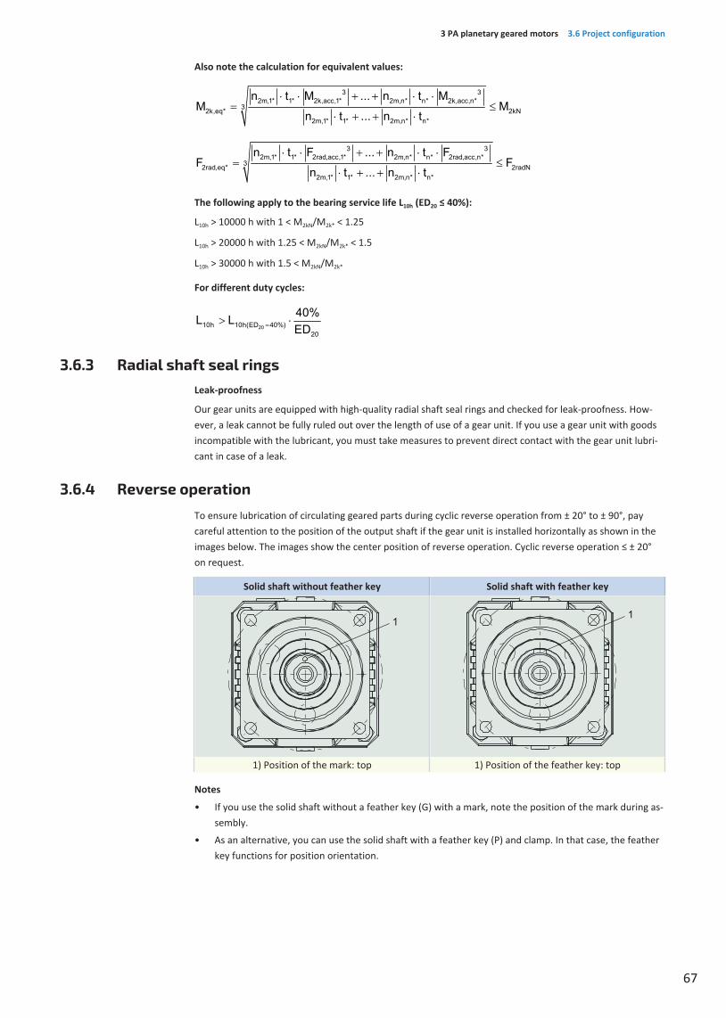
3.6.4 Reverse operation
To ensure lubrication of circulating geared parts during cyclic reverse operation from ± 20° to ± 90°, paycareful attention to the position of the output shaft if the gear unit is installed horizontally as shown in theimages below. The images show the center position of reverse operation. Cyclic reverse operation ≤ ± 20°on request.
Solid shaft without feather key Solid shaft with feather key
11
1) Position of the mark: top 1) Position of the feather key: top
Notes
• If you use the solid shaft without a feather key (G) with a mark, note the position of the mark during as-sembly.
• As an alternative, you can use the solid shaft with a feather key (P) and clamp. In that case, the featherkey functions for position orientation.
3 PA planetary geared motors 3.6 Project configuration
67
3.7 Additional documentationAdditional documentation related to the product can be found at http://www.stoeber.de/en/download
Enter the ID of the documentation in the Search... field.
Documentation ID
Operating manual for P/PA/PE/PH/PHA/PHQ/PHQA/PHV/PHVA planetarygear units and planetary geared motors
443029_en
Lubricant filling quantities for gear units 441871
3.7 Additional documentation 3 PA planetary geared motors