Document: 105M0340 Rev. L (09/16)
Page 1 of 13
GE Measurement & Control
2300 Vibration Monitors Bently Nevada* Asset Condition Monitoring
Description
The 2300 Vibration Monitors provide cost-effective continuous
vibration monitoring and protection capabilities for less critical and
spared machinery. They are specifically designed to continuously
monitor and protect essential medium to low criticality machinery
in a wide range of industries including: oil & gas, power generation,
water treatment, pulp & paper, manufacturing, mining, cement, and other industries.
The 2300 Vibration Monitors deliver vibration monitoring and high
vibration level alarming. They include two channels of seismic or
proximity measurement inputs from various accelerometer,
velomitor and proximitor types, a speed input channel for time-
synchronous measurements, and outputs for relay contacts. The
2300/20 monitor features a configurable 4-20 mA output which
interfaces more points to a DCS. The 2300/25 monitor features
System 1* connectivity for Trendmaster SPA interface which enables users to leverage existing DSM SPA infrastructure.
The 2300 Vibration Monitors are designed for use on a broad
range of machine trains or individual casings where the sensor
point count fits the monitor’s channel count and where advanced signal processing is desired.
Document: 105M0340 Rev. L (09/16)
Page 2 of 13
Monitor Key Features
2300/20 Two 4-20mA outputs
Two relay outputs with programmable setpoints
Ethernet 10/100 Base-T communication for
configuration using Bently Nevada Monitor
Configuration software (included)
One dedicated speed and Keyphasor* channel
supporting Proximity probes, Magnetic pickup
and Proximity switch type sensors
Three buffered transducer outputs (including
Keyphasor signal) providing short circuit and EMI
protection. Buffered outputs for each signal are
through BNC connectors.
Continuous monitoring and protection
LCD display showing vibration measurements,
setpoints, and speed
Two acceleration/velocity/proximity inputs with
synchronized sampling for advanced diagnostics
Key measurements (Direct pk, Direct rms, Derived
pk, Velocity pk, Velocity rms, Displacement pp,
Displacement rms, Speed) real-time provided
with alarm configuration
LEDs show the monitor status
Local contacts for positive engagement of
channel bypass, configuration lockout, and reset
Modbus® over Ethernet
2300/25 Trendmaster SPA interface
Two relay outputs with programmable setpoints
Ethernet 10/100 Base-T communication for
configuration using Bently Nevada Monitor
Configuration software (included)
One dedicated speed and Keyphasor channel
supporting Proximity probes, Magnetic pickup
and Proximity switch type sensors
Three buffered transducer outputs (including
Keyphasor signal) providing short circuit and EMI
protection. Buffered outputs for each signal are
through BNC connectors.
Continuous monitoring and protection
LCD display showing vibration amplitude,
setpoints, and speed
Two acceleration/velocity/proximity inputs with
synchronized sampling for advanced diagnostics
Key measurements (Direct pk, Direct rms, Derived
pk, Velocity pk, Velocity rms, Displacement pp,
Displacement rms, Speed) real-time provided
with alarm configuration
LEDs show the monitor status
Local contacts for positive engagement of
channel bypass, configuration lockout, and reset
Modbus® over Ethernet
Recommended for Demonstration Kit 2300/20_KIT-003-02-01
1 - 2300/20 Monitor
1 - 6 ft. (1.8M) shielded Ethernet cable
2 - Accelerometer sensors
2 - 15 ft. (4.8M) accelerometer cables
100M9465-01 BN Monitor Configuration SW/FW DVD
To be ordered separately: 110M7102-01 Power supply for DIN rail mounting,
100/240AC to 24DC/1.3A
(-25°C ~70°C, 22.5*99*107 mm)
Document: 105M0340 Rev. L (09/16)
Page 3 of 13
Specifications
Inputs / Outputs
Power Input:
DC Input: 18~36VDC, max 7.5W
Supports ICP Accelerometers Channel Type:
o Configurable Bandpass filter: 0.2 Hz to 20
kHz
o Scale Factor range: 5 to 1000 mV/g
o Full scale range: 2 to 80 g peak
o Bias output voltage: -12VDC (for AM3100T2-
Z2)
o Configurable Upper OK limit: -0.25 to -22 V
(greater than lower ok)
o Configurable Lower OK limit: -0.25 to -22 V
(less than upper ok)
o Current Sink Source: 3.3 mA ± 5%
o Open Circuit Voltage: -21 to -24 VDC
Supports Velocity Channel Type:
o Configurable Bandpass filter: 0.2 Hz to 20
kHz
o Scale Factor range: 5 to 1000 mV/in/s
o Full scale range: 0 to 50 in/s peak
o Configurable Upper OK limit: -0.25 to -22 V
(greater than lower ok)
o Configurable Lower OK limit: -0.25 to -22 V
(less than upper ok)
Supports Radial Vibration Channel Type:
o Configurable Bandpass filter: 0.2 Hz to 20
kHz
o Scale Factor range: 5 to 1000 mV/mil
o Full scale range: 0 to 160 mil peak-peak
o Configurable Upper OK limit: -0.25 to -22 V
(greater than lower ok)
o Configurable Lower OK limit: -0.25 to -22 V
(less than upper ok)
Accuracy: ±1% of full scale range
Supports custom accelerometers (2 or 3 wires)
Independent 24-bit ADCs on both channels
Speed/Keyphasor Inputs
Supported Keyphasor transducers include:
o Proximity probe
o Proximity switch
o Magnetic Pickup
Supports multiple events per revolution and
event ratios for speed inputs up to 20 kHz
Threshold voltage resolution: 0.1VDC
Proximity Transducer Interface:
o Supply Voltage: -22.8 to –25.2 VDC
o Maximum Rated Current: 15 mA
o Short Circuit Current: 15.1 mA to 23.6 mA
o Accuracy: ±1% of full scale range
o Input Impedance: 3-wire Voltage Mode, 10
kΩ
o Rpm range: 1 to 120,000
Proximity Switch Interface:
o Supply Voltage: -10 to -24 VDC
o Lower Not Ok limit: -2.75 ±0.05 V
o Rpm range: 1 to 120,000
Magnetic Pick up:
o Input voltage up to ±125V (250Vp-p)
o Rpm range: 200 to 120,000
Contact Inputs
Monitor provides the capability of 3 contact inputs
with terminals. One is used for configuration lock,
one is for latched alarm/relay reset function, and the
3rd one is used for monitor Alarm/Relay Inhibit.
Activate: 0 to 10 kΩ
De-activate: 150 kΩ to infinite
Button Inputs
External button to reset latched alarm and relay
One buried button provides 3 functions:
o Display monitor information including:
User account name
IP address
FW/HW version
Document: 105M0340 Rev. L (09/16)
Page 4 of 13
o LCD contrast adjustment
o Reset settings to default including:
User account name
Password
Network configuration
Jumper between COM & Chassis GND
There is a 2-pin terminal interface which allows
connection of COM and Chassis GND together.
Alternatively, COM can be connected to earth
ground separately through a terminal.
Buffered Output
There are three buffered outputs available on the
monitor through BNC connectors:
o 2 Vibration Outputs
o 1 Speed Output
Relay Output
There are two dry-contact relay outputs
May be normally energized or de-energized
No output feedback determination
Relay circuit specification in Non-Hazardous
area:
o Type: Single pole, double throw
o Sealing: Epoxy sealed
o Contact life:
100,000 cycles @ 5 amps 250 VAC
200,000 @ 1 amp, 24 VDC
o Insulation resistance:
1000 MΩ minimum @ 500 VDC
o Relay closed contact resistance:
1 Ω maximum
o Relay open contact resistance:
1 MΩ minimum
o Maximum switched contact voltage:
250V AC /250V DC
o Maximum breaking contact current:
6A @250VAC / 6A @24VDC
o Maximum switched power:
1500VA AC / 150 Watts DC
Relay circuit specification in Hazardous area:
o Maximum switched contact voltage and
current: 6A @24VAC / 5A @30VAC / 5.8A
@24VDC / 4A @30VDC
4-20mA Output (2300/20)
Two 4-20mA outputs
4 to 20mA output values are proportional to the
full-scale of the associated measurement
Each output can be software configured to
output any variable
Voltage compliance: 0 to +12Vdc range across
load
Load resistance: 0 to 600Ω
Resolution: 0.3662uA
Accuracy: 1% over operating temperature range
Update rate: 100ms
Configurable with default 2mA clamp current
No output feedback determination
SPA Output (2300/25)
Input signal range
o High AC: 8Vpp
o Low AC: 1.6Vpp
o DC GAP: 0 to -20Vdc (max measurable AC
signal is 1Vpp)
Accuracy
o High/Low AC: ±1% of Full-Scale at 100Hz
o DC GAP: ±0.5V (measurable AC accuracy:
±20mV)
Frequency response
o 10Hz to 3000Hz ±5%
LEDs
OK: Indicates when the monitor is operating
properly
Protection fault: Indicates that there is a
hardware fault that is impacting alarm
determination
User inhibit: indicates the alarm/relays have been
intentionally inhibited from operation
Bypass: indicates user initiated bypass action
Relay status: indicates if relays have been
activated
Document: 105M0340 Rev. L (09/16)
Page 5 of 13
TX/RX: Indicates the Ethernet status and monitor
communicating with remote software
Speed channel status
Channel Alarm Status:
o Alert LED: engages if any channel is in alert
state
o Danger LED: engages if any channel is in
danger state
LCD
LCD display allows viewing machine speed, vibration
measurements value, setpoints, and configuration information.
Communications
Ethernet
Ethernet, 10Base-T and 100Base-TX. Conforms
to IEEE802.3
RJ-45 for 10Base-T/100Base-TX Ethernet cabling
Cable length: 100 meters (328 ft.) maximum
Environmental Limits
Operating Temperature:
-30 °C to +65 °C (-22 °F to +149 °F)
Storage Temperature:
-40 °C to +85 °C (-40 °F to +185 °F)
Humidity:
Up to 95%, non-condensing
Vibration Limitation:
3g
Battery Life for Real Time Clock:
Powered: 38 years @ 50°C (122 °F)
Un-powered: 12 years @ 50°C (122 °F)
Compliance and Certifications
General and Electrical Safety:
UL Std. No. 61010-1 (3rd Edition)
CAN/CSA C22.2 No. 61010-1-12
2014/35/EU Low Voltage
Standard:
EN61010-1: 2010
European Community Directives: LV Directive 2014/35/EU
EMC Standards:
EN61000-6-2 Immunity for Industrial Environments EN61000-6-4 Emissions for Industrial Environments EN61326-1 Electrical equipment for measurement, control and laboratory use - EMC requirements European Community Directives: EMC Directive 2014/30/EU
Hazardous Area Approvals
For a detailed listing of country and product
specific approvals, refer to the Approvals Quick
Reference Guide (document 108M1756) located at the following website: www.GEmeasurement.com.
CSA/NRTL/C
Class I, Division 2/Zone 2 AEx/Ex nA nC [ic] IIC T4 Gc Class I, Div. 2, Groups A, B, C, D
ATEX/IECEx
II 3 G Ex nA nC [ic] IIC T4 Gc
ATEX 2014/34/EU
Intrinsic Safety Parameters:
For Proximitor Transducer:
Uo: 24V; Io: 46mA; Co: 200nF; Lo: 1mH
For Accelerometer Transducer:
Uo: 24V; Io: 3.3mA; Co: 200nF; Lo: 1mH
FOR SPA POWER (2300/25 Only):
Ui=15V; Ii=150mA; Pi=560mW; Ci=0; Li=0
FOR SPA SIGNAL (2300/25 Only): Ui=12V; Ii=12mA; Pi=36mW; Ci=0; Li=0
Physical
Dimensions (Width x Depth x Height)
127mm x 127mm x 76.2mm (5in x 5in x 3in)
Weight
1.03kg (2.26lbs)
Document: 105M0340 Rev. L (09/16)
Page 6 of 13
Mounting
Panel mount or DIN rail (adapter included)
Ordering Information
For a detailed listing of country and product
specific approvals, refer to the Approvals Quick
Reference Guide (document 108M1756) located at the following website: www.GEmeasurement.com.
2300 Series Vibration Monitor
2300/20-AA-BB: Monitor with 4-20ma Outputs
(including DIN rail mount assembly, manual and monitor configuration software)
2300/25-AA: Monitor with SPA Outputs (including
DIN rail mount assembly, manual and monitor configuration software)
AA: Approvals Option 00
None
02
Multiple Explosive Atmosphere
Certifications (ATEX/IECEx/CSA)
BB: Software License for System 1 Evo Connection
00
Monitor without License
01
Monitor with License
2300/20_KIT-AAA-BB-CC: Bently Nevada 2300/20 Condition Monitoring System Kit
2300/25_KIT-AAA-BB: Bently Nevada 2300/25 Condition Monitoring System Kit
AAA: Configuration
001
1 - 2300/20 or 2300/25 Monitor
1 - 6 ft. (1.8m) shielded Ethernet cable
1 – 13 x 15 x 8 in. (338 x 389 x 209mm)
fiberglass housing with window
2 - Accelerometer sensors
2 – 15 ft. (4.8m) accelerometer cables
(Excluding Keyphasor sensor and 24 VDC
power supply 1)
002
1 - 2300/20 or 2300/25 Monitor
1 - 6 ft. shielded Ethernet cable
1 - 13x15x8 in. fiberglass housing with
window
1 - Accelerometer sensor
1 - 15 ft. (4.8m) accelerometer cable
(Excluding Keyphasor sensor and 24VDC
power supply1)
003
1 - 2300/20 or 2300/25 Monitor
1 - 6 ft. shielded Ethernet cable
2 - Accelerometer sensors
2 - 15 ft. (4.8m). accelerometer cables
(Excluding Keyphasor sensor, enclosure
and 24 VDC power supply1)
BB: Approvals Option
00
None
02
Multiple Explosive Atmosphere
Certifications (ATEX/IECEx/CSA)
CC: Software License for System 1 Evo Connection
00
Monitor without License
01
Monitor with License
3071/13-AA-BB: System 1 2300 Series Device Import
AA: Not available for 2300 monitor
00
BB: Quantity of 2300 Monitoring Systems ## - Numeric Entry [1->n]
Notes:
3071/13 is only applicable for 2300 monitors that
are installed/purchased without the System 1
Evolution device license.
System 1 Evolution software requires a separate
order. Refer to the System 1 datasheet
Document: 105M0340 Rev. L (09/16)
Page 7 of 13
(document 108M5214) for detailed ordering
information.
The maximum number of 2300 monitor
connections is 350 in System 1 16.1. (This number
will be increased in later versions.)
AA option is for vbOnline Pro Device.
1 We provide 3 kinds of power supplies with different temperature
range and different power. Please check Accessories below for
the details.
Accessories
106M7607-01 Power supply for DIN rail mounting,
100/240AC to 24DC/1.5A Certifications (ATEX) (-25°C ~70°C, 35*99*95 mm)
(One power can drive max 4 monitors)
110M7102-01 Power supply for DIN rail mounting, 100/240AC to 24DC/1.3A Certifications (CID2 by UL)
(-25°C ~70°C, 22.5*99*107 mm)
(One power can drive max 4 monitors.)
106M6694-01 Power supply for DIN rail mounting,
110/220AC to 24VDC/5A Certifications (ATEX, IECEx, CID2 by UL) (-40°C ~70°C, 40*130*125 mm)
(One power can drive max 10 monitors.)
105M6193-01 Fiberglass NEMA 4X/IP68
weatherproof housing with window
in door (includes mounting plate for monitor)
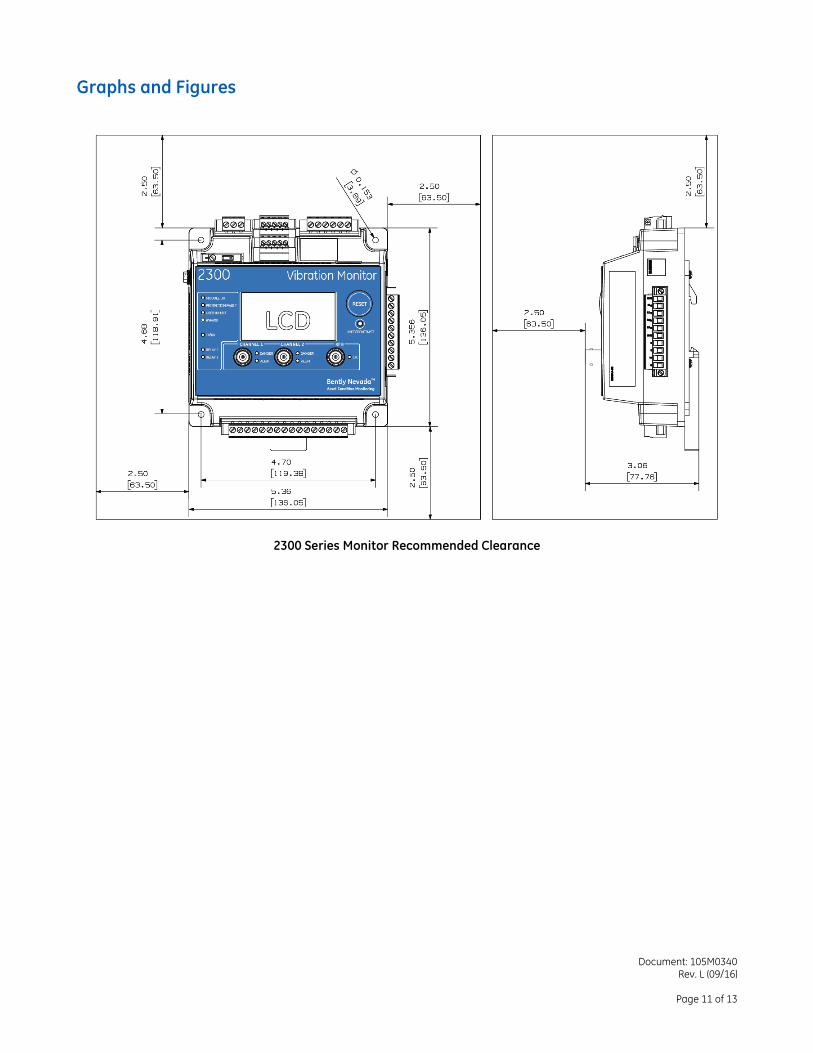
Dimensions:
(Width x Depth x Height)
338.3 x 389.1 x 209.8mm (13.3 x 15.3 x 8.2in)
AM3100T2-Z2 Accelerometer sensor
Document: 105M0340 Rev. L (09/16)
Page 8 of 13
330400/330425 Accelerometer sensor
330500 Velomitor
330505 Velomitor
330525 Velomitor
190501 Velomitor
100M0741 Proximity Switch
Document: 105M0340 Rev. L (09/16)
Page 9 of 13
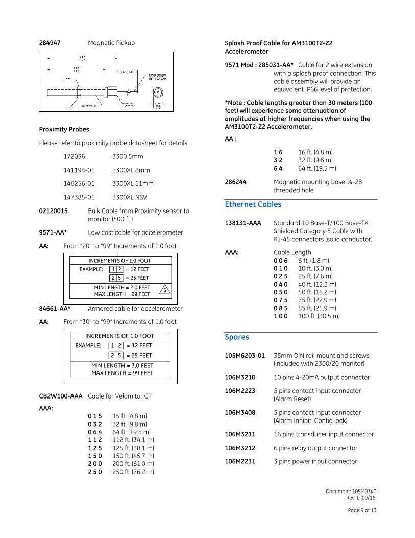
284947 Magnetic Pickup
Proximity Probes
Please refer to proximity probe datasheet for details
172036 3300 5mm
141194-01 3300XL 8mm
146256-01 3300XL 11mm
147385-01 3300XL NSV
02120015 Bulk Cable from Proximity sensor to monitor (500 ft.)
9571-AA* Low cost cable for accelerometer
AA: From “20” to “99” Increments of 1.0 foot
84661-AA* Armored cable for accelerometer
AA: From “30” to “99” Increments of 1.0 foot
CB2W100-AAA Cable for Velomitor CT
AAA: 0 1 5 15 ft. (4.8 m) 0 3 2 32 ft. (9.8 m) 0 6 4 64 ft. (19.5 m) 1 1 2 112 ft. (34.1 m) 1 2 5 125 ft. (38.1 m) 1 5 0 150 ft. (45.7 m) 2 0 0 200 ft. (61.0 m) 2 5 0 250 ft. (76.2 m)
Splash Proof Cable for AM3100T2-Z2 Accelerometer
9571 Mod : 285031-AA* Cable for 2 wire extension
with a splash proof connection. This
cable assembly will provide an equivalent IP66 level of protection.
*Note : Cable lengths greater than 30 meters (100 feet) will experience some attenuation of amplitudes at higher frequencies when using the AM3100T2-Z2 Accelerometer.
AA :
1 6 16 ft. (4.8 m) 3 2 32 ft. (9.8 m)
6 4 64 ft. (19.5 m)
286244 Magnetic mounting base ¼-28 threaded hole
Ethernet Cables
138131-AAA Standard 10 Base-T/100 Base-TX
Shielded Category 5 Cable with RJ-45 connectors (solid conductor)
AAA: Cable Length 0 0 6 6 ft. (1.8 m) 0 1 0 10 ft. (3.0 m) 0 2 5 25 ft. (7.6 m) 0 4 0 40 ft. (12.2 m) 0 5 0 50 ft. (15.2 m) 0 7 5 75 ft. (22.9 m) 0 8 5 85 ft. (25.9 m) 1 0 0 100 ft. (30.5 m)
Spares
105M6203-01 35mm DIN rail mount and screws
(included with 2300/20 monitor)
106M3210 10 pins 4-20mA output connector
106M2223 5 pins contact input connector (Alarm Reset)
106M3408 5 pins contact input connector (Alarm Inhibit, Config lock)
106M3211 16 pins transducer input connector
106M3212 6 pins relay output connector
106M2231 3 pins power input connector
Document: 105M0340 Rev. L (09/16)
Page 10 of 13
Software
100M9465-01 BN Monitor Configuration SW/FW
DVD
BNMC version 5.2 or greater
2300 series monitor firmware
(DVD includes 2300 Series Software Guide)
User Manuals
2300 Series Operation and Maintenance Manual (Document 105M0341)
2300 Field Wiring Diagram (Document 106M5801)
2300 Series Software Guide (Document 107M7626)
Training Materials Link
http://ge-
energy.turnstilesystems.com/ProgramDetail.aspx/23
00Monitor
Document: 105M0340 Rev. L (09/16)
Page 11 of 13
Graphs and Figures
2300 Series Monitor Recommended Clearance
Document: 105M0340 Rev. L (09/16)
Page 13 of 13
2300/25 Wiring Diagram
Note: 2300/20 and 2300/25 use the same interface connector for recorder output or SPA output.
Modbus® is a registered trademark of Schneider Electric USA, INC.
© 2014-2016 Bently Nevada, Inc. All rights reserved. * Denotes a trademark of Bently Nevada, Inc., a wholly owned subsidiary of General Electric Company.
The information contained in this document is subject to change without prior notice. Printed in USA. Uncontrolled when transmitted electronically.
1631 Bently Parkway South, Minden, Nevada USA 89423 Phone: 775.782.3611 Fax: 775.215.2873
www.GEmeasurement.com