+ All Categories
Home > Documents > 2301.Execution of works - keralapwd.gov.in

2301.Execution of works - keralapwd.gov.in

Date post: 18-Dec-2021
Category:
Upload: others
View: 2 times
Download: 0 times
Share this document with a friend
62
Kerala PWD Manual Execution - General 319 Section 2300 2301.Execution of works 2301.1.General The Assistant Engineer is the first responsible Engineering officer at the site of any construction work like buildings, bridge, roads, etc., who looks after day to day working of the project. The efforts taken & the strict supervision on his part have direct relation to quality of work. He shall therefore get conversant with various aspects of execution of work, to discharge the duties efficiently. The Assistant Engineer deputes one or more Overseers to a work for the effective supervision and proper quality control. 2302. Handing Over Site The Assistant Engineer will hand over the site to the Contractor as specified in section 2202.1 of Contract Management. 2302.1 Study of Concerned Documents by the Contractor The basic document related to work is the estimate. Therefore it shall be thoroughly studied for its scope & provisions. The relevant valid drawings shall also be studied & understood properly. The tender document & specification of items must be clearly understood. The provision in the Contract document and schedule shall be studied with reference to time limit, escalation, defect liability, progress schedule & quantities & rates mentioned. The specifications relevant to the schedule of items shall also be refreshed. The site may be finalized and desired location of site office, storage sheds, batching plant, casting yard, labour camp etc.fixed. Source of construction material like sand, aggregates, cement and steel etc. also to be identified. Draw a detailed work programme on the basis of availability of plant, material manpower etc. for the smooth progress of work. 2302.2.Site office The contractor shall set up the site office and the following shall be available in the office at all times. 2302.3. Drawings All drawings like plan, elevation, layout plan, sections, R.C.C. layout, alignment plan etc. shall be maintained in site office. Such plans are required for daily reference & during the inspection of higher officers. These drawings shall be properly preserved. Such drawings shall bear the signatures of officers approving such drawings, to avoid use of any other drawing. Out dated or superseded drawings shall be clearly marked as such & removed from site. Also all drawings in CD may be kept at the office. 2302.4. Estimate & Tender Copy of the technically sanctioned estimate shall be kept in site office under custody of Assisstant Engineer for correct reference. Similarly, the contract copy containing all documents shall be kept at site for study & guidance. 2302.5. Other Registers Some other registers are also required to be maintained like dewatering record for foundation, labour attendance/ wages register maintained by the contractor. 2302.6.Instruments to be Kept at Site office Essential instruments for execution of work shall be kept at site or carried along with if possible. The A.E. shall take care for safe custody & proper calibration of the instruments. If there is loss/theft of any instrument, in that case the cost of instrument can be recovered from A.E. These are Dumpy Level, Theodolite Vernier Caliper and Tapes. Tapes are required to be carried always for checking measurements. Generally, following tapes shall be available. i. Metallic tape 15 m &-30 m. ii. Steel tape lm, 15 m, 30m. iii. Cloth tape 15m, & 30 m. In addition each A.E. must carry a 3 m. steel tape in his pocket at all times. The following tools are also helpful in execution.
Transcript

Kerala PWD Manual Execution - General

319

Section 2300

2301.Execution of works

2301.1.General

The Assistant Engineer is the first responsible Engineering officer at the site of any construction work

like buildings, bridge, roads, etc., who looks after day to day working of the project. The efforts taken &

the strict supervision on his part have direct relation to quality of work. He shall therefore get conversant

with various aspects of execution of work, to discharge the duties efficiently. The Assistant Engineer

deputes one or more Overseers to a work for the effective supervision and proper quality control.

2302. Handing Over Site

The Assistant Engineer will hand over the site to the Contractor as specified in section 2202.1 of Contract

Management.

2302.1 Study of Concerned Documents by the Contractor

The basic document related to work is the estimate. Therefore it shall be thoroughly studied for its

scope & provisions. The relevant valid drawings shall also be studied & understood properly. The tender

document & specification of items must be clearly understood. The provision in the Contract document

and schedule shall be studied with reference to time limit, escalation, defect liability, progress schedule &

quantities & rates mentioned. The specifications relevant to the schedule of items shall also be refreshed.

The site may be finalized and desired location of site office, storage sheds, batching plant, casting yard,

labour camp etc.fixed. Source of construction material like sand, aggregates, cement and steel etc. also to

be identified. Draw a detailed work programme on the basis of availability of plant, material manpower

etc. for the smooth progress of work.

2302.2.Site office

The contractor shall set up the site office and the following shall be available in the office at all

times.

2302.3. Drawings

All drawings like plan, elevation, layout plan, sections, R.C.C. layout, alignment plan etc. shall be

maintained in site office. Such plans are required for daily reference & during the inspection of higher

officers. These drawings shall be properly preserved. Such drawings shall bear the signatures of officers

approving such drawings, to avoid use of any other drawing. Out dated or superseded drawings shall be

clearly marked as such & removed from site. Also all drawings in CD may be kept at the office.

2302.4. Estimate & Tender

Copy of the technically sanctioned estimate shall be kept in site office under custody of Assisstant

Engineer for correct reference. Similarly, the contract copy containing all documents shall be kept at site

for study & guidance.

2302.5. Other Registers

Some other registers are also required to be maintained like dewatering record for foundation,

labour attendance/ wages register maintained by the contractor.

2302.6.Instruments to be Kept at Site office

Essential instruments for execution of work shall be kept at site or carried along with if possible.

The A.E. shall take care for safe custody & proper calibration of the instruments. If there is loss/theft of

any instrument, in that case the cost of instrument can be recovered from A.E.

These are Dumpy Level, Theodolite Vernier Caliper and Tapes. Tapes are required to be carried always

for checking measurements. Generally, following tapes shall be available.

i. Metallic tape 15 m &-30 m.

ii. Steel tape lm, 15 m, 30m.

iii. Cloth tape 15m, & 30 m.

In addition each A.E. must carry a 3 m. steel tape in his pocket at all times. The following tools are also

helpful in execution.

Kerala PWD Manual Execution - General

320

hammer and peg

chisel

brush

Nylon string

1 m straight edge + wedge

Spirit level

1m meter square template

Chalk

Clip board

File folder

Torch with batteries

Sign board

Red & green flag (for road works)

Umbrella/ raincoat

2303. Modern Instruments

The recent advances in Engineering instruments and survey equipments like Total Station etc. need to

be utilized to enhance capability of the department and improve quality in execution. Govt. has decided to

encourage use of more modern instruments. KHRI (Kerala Highway Research Institute) shall impart

necessary training to all Engineers.

2303.1.Tools and Plants

Available modern tools and plants shall be used for speed and quality wherever possible.

2304.Safe constructional Practices

Public safety as well as safety of the workforce is of utmost importance. In case of buildings the

provisions of Part 7 of national Building Code 2005 shall apply. For roads and bridges refer IRC SP 55

2305.Environmental Considerations

For all construction activities, provisions of environmental requirements in the code and manual

shall be followed. All necessary clearances at the local, state and national levels shall be obtained prior to

the start of work.

2306.Quality Assurance of works

For all construction activities the provisions of quality manual shall be followed.

2307.Clearing and Grubbing

Before any construction starts the site must be cleared of debris. All materials including trees,

grass, vegetation, crops and structures, which fall within the area, must be removed. All stumps and roots

need to be removed (grubbed out) and the holes/ hollows left must be filled with compacted suitable fill

material.

Existing structures that has to be demolished, shall be done as per the provision of Section 5 of

Part 7, National building Code 2005.

The products of the clearing are to be stacked in such place and manner as may be ordered by the

Assistant Engineer and the ground shall be left in a perfectly clear condition. All products of the clearing

shall be the property of Government. These shall be disposed of as per existing rules without damage to

the environment.

2307.1.Layout of the Work

After having cleared the site, fix up permanent benchmarks, guide reference pillars, and transfer the

alignment with the help of reference pillars fixed at site during the location survey. The layout shall be

done correctly to true lines, dimensions and locations as per approved drawings. The junction pillars

beyond layout area shall be erected marked, painted and maintained throughout for reference. It shall be

crosschecked for right angles, diagonals etc. The Assistant Executive Engineer shall be approved all

layouts.

2307.2.Excavation & Approval of Foundation

Before any excavation, including the removal of any area of unsuitable materials, cross-sections

shall be taken as far as possible of the undisturbed ground. From this information, and the cross sections

Kerala PWD Manual Execution - General

321

taken of the completed road, earthwork quantities can be calculated. No existing material, which will

remain in the completed works, shall be loosened unnecessarily during excavation. Excavation works,

along with all construction activities, must be undertaken in as safe a manner as possible to minimize the

dangers to road users and the contractor’s personnel. The Assistant Executive Engineer shall be approved

all excavations.

2307.3. Excavation for Structures

Excavation for structures shall consist of the removal of material for the construction of

foundations for buildings, bridges, culverts, retaining walls, headwalls, cutoff wails, pipe culverts and

other similar structures, in accordance with the requirements of these Specifications and the lines and

dimensions shown on the drawings or as indicated by the Assistant Engineer. The work shall include

construction of the necessary cofferdams and cribs and their subsequent removal; all necessary sheeting,

shoring, bracing, draining and pumping; the removal of all logs, stumps, grubs and other deleterious

matter and obstructions, necessary for placing the foundations; trimming bottoms of excavations;

backfilling and clearing up the site and the disposal of all surplus material.

Old curiosities, relics, coins, minerals and any other item of archeological importance found on

excavation or pulling down shall be the property of the Government. Shall any ancient masonry or other

old work of interest be opened up, or any religious edifice or relic be involved in removal or destruction in

the execution of a work, a clear report on the matter shall be sent to Government through the Chief

Engineer and orders obtained before the demolition or removal of such works or relics. Regarding the

disposal of old curiosities, the Assistant Executive Engineer shall consult the District Collector.

2307.4. Dewatering and protection

Normally, open foundations shall be laid dry. Where water is met with in excavation due to

stream flow, seepage, springs, rain or other reasons, the Contractor shall take adequate measures to keep

the foundation trenches dry when so required and to protect the green concrete/masonry against damage

by erosion or sudden rising of water level. The Contractor shall take all precautions in diverting channels

and in discharging the drained water as not to cause damage to the works, crops or any other property.

2307.5.Preparation of foundation:

The bottom of the foundation shall be leveled both longitudinally and transversely or stepped as

directed by the Assistant Engineer. Before footing is laid, the surface shall be slightly watered and

rammed. If, during inspection, it is found that the contractor has over excavated the foundation in excess

by what is shown in the drawings, he shall not be allowed to refill this with earth but, the additional

excavation shall be got filled up by concrete or masonry of such proportions as decided by the Executive

Engineer. No extra cost is payable to the contractor on this account.

When rock or other hard strata is encountered, it shall be freed of all soft and loose material, cleaned and

cut to a firm surface either level and stepped as directed by the Assistant Engineer. All seams shall be

cleaned out and filled with cement mortar or grout to the satisfaction of the Assistant Engineer.

When foundation piles are used, the excavation of each pit shall be substantially completed before

beginning pile-driving operations therein.

2307.6. Public safety:

Near towns, villages and all frequented places, trenches and foundation pits shall be securely

fenced and provided with proper caution signs and marked with red lights at night to avoid accidents. The

Contractor shall take adequate protective measures to see that the excavation operations do not affect or

damage adjoining structures. For safety precautions, guidance may be taken from IS: 3764.

2307.7. Backfilling

Backfilling shall be done with approved material after concrete or masonry is fully set and carried

out in such a way as not to cause undue thrust on any part of the structure. All space between foundation

masonry or concrete and the sides of excavation shall be refilled to the original surface in layers not

exceeding 150 mm compacted thicknesses. The compaction shall be done with the help of suitable

equipment such as mechanical tamper, rammer, plate vibrator etc., after necessary watering, so as to

achieve a density not less than the field density before excavation.

Kerala PWD Manual Execution - General

322

2307.8. Excavated Material

Excavated materials need assessing as suitable or unsuitable. Suitable materials shall be used

when possible in the works. The excavated materials can be temporarily stockpiled, but must cause no

damage to services or property. Any excess suitable material, which is not required for the construction of

the Works or any material classified as unsuitable is the property of Department. The Contractor shall

stockpile these materials separately, as directed, or place the material in an approved location on site. To

be suitable as fill material the soil must not contain any vegetable matter. (Shall details as per MoRTH be

given)

2307.9. Borrow Pits

The borrow pits, if any required, shall be kept as drained as possible. It shall be made only at the specified

distance from the proposed structure. It shall not be cut opened where they might:-

a) Affect the stability or safety of the highway, or any railway or other structures, which may

be present.

b) Prevent natural or artificial drainage or irrigation.

c) Damage adjacent property or future expansion plans for the highway.

After the correct layout is marked, cross checked and approved the excavation for foundation starts.

Before starting excavation, it is necessary that ground levels are taken correctly and recorded in level

book and the foundation plan. The levels at all junctions of building shall be taken at a large number of

points to give correct idea of ground occupied in foundation.

Unauthorised entries to site of work shall be prohibited. The contractor shall obtain proper license for

explosives & whenever explosives are required to be stored at site, proper magazines as per rules must be

insisted on.

2308. Formwork

The concrete acquires exact shape of the mould in which it is placed. For good concrete work,

shuttering, centering & concreting operations are three important things. It is therefore important that

principle of sound design, erection of the shuttering is strictly followed. Any negligence on this count may

lead to mishaps resulting in loss of human life & Government money.

The provisions of clause 11 of IS 456:2000 shall be followed for formwork. The plan of the formwork

proposed to be employed by contractor shall be obtained and examined by the Assistant Executive

Engineer in respect of contracts entered into by him or higher officers. In respect of contracts executed by

the Assistant Engineer, the plans shall be obtained and examined by the Assistant Engineer. If such plans

are not satisfactory to the Assistant Executive Engineer or the Assistant Engineer as the case may be, the

contractor shall be asked to make such changes in them as may be required.

The formwork shall be robust and strong and the joints shall be leak-proof and must be properly sealed.

The number of joints in the formwork shall be kept to a minimum by using large size panels.

2308.1. Forms

In designing forms, concrete shall be treated as a fluid weighing 2400 Kg. per cubic metre and in

addition a live load of 700 Kg. per square metre on horizontal projection of surfaces shall also be allowed.

Forms shall be so designed and constructed that they may be removed without injury to the concrete.

Blocks and bracings shall be removed with the forms and in no case shall any portions of the wood forms

be left in the concrete. The forms must be so constructed, set and maintained that the finished concrete

shall be of the form and dimensions shown on the plans and true to line and grade. Allowance for the

deflection of forms and for shrinkage and settlement of staging or centering in addition to the allowance

for dead loads, and camber, as shown upon the plans shall be provided.

Forms used a second time shall be thoroughly cleaned and shall be free from bulge, splits or

warps. In case of compaction of concrete by vibration, the forms shall be so designed as to withstand the

effects of vibration. The formwork shall be coated with an approved release agent that will effectively

prevent sticking/ coating the reinforcement and will not stain the concrete surface. Lubricating (machine

oils) shall not be used for this purpose.

The forms shall remain in place for the period required as per clause 11.3 of IS 456 2000. The foregoing

specification for forms shall also apply to steel forms. The sheets used shall be of such thickness that the

Kerala PWD Manual Execution - General

323

forms will remain true to shape. All bolt and rivet heads shall be countersunk. Clamps, pins or other

connecting devices shall be designed to hold the forms rigidly together and to allow removal without

injury to the concrete. Steel forms, which do not present a smooth surface or line up properly, shall not be

used. Special care shall be exercised to keep steel forms free from rust, grease or other foreign matter,

which will discolour the concrete.

Broadly, the following steps shall be observed

i) Proper design of centering system for all dead & live loads that is approved by competent officer.

ii) Proper use of shuttering & centering material. Centering shall be of steel props & beams

(telescopic), shuttering of waterproof ply board (preferably laminated on one side) & steel

centering plates.

iii) The erection shall be done carefully. The ground on which it is to be supported shall be firm and

unyielding even during rains. The supports shall be adequately braced.

iv) After erection, the Assistant Engineer and Assistant Executive Engineer shall check it for

dimension, line, level & safety.

v) The centering shall be removed only after the minimum prescribed curing period is over.

2308.2. Scaffolding

Scaffolding is the contractor's responsibility, but the departmental officer must ensure that the

scaffolding provided is adequate and properly fixed together and strengthened so that workmen and others

using them can carry on work safely.

2308.3. Shuttering and Centering Work

The Executive Engineer may require the contractor to use screw jacks or hardwood wedges to take

up any settlement in staging or centering either before or during the placing of the concrete. All staging

and false work shall be built on foundations of sufficient strength to carry the load without appreciable

deformation. On stable soils, like rock, shale, stiff clay and sands free from scour, spread footings may be

used and shall be of size to be determined by the load to be supported. In other locations, the formwork

shall be supported on piles. The piles shall be spaced and driven to support the required loads without

settlement

Special measures in the design of formwork shall be taken to ensure that it does not hinder the shrinkage

of concrete. The soffit of the formwork shall be so designed as to ensure that the formwork does not

restrain the shortening and/or hogging of beams during pre-stressing. Any cutouts or openings provided in

any structural member to facilitate erection of formwork shall be closed with the same grade of concrete

as the adjoining structure immediately after removal of formwork ensuring watertight joints. Provision

shall be made for safe access on, to and about the formwork at the levels as required. Close watch shall be

maintained to check for settlement of formwork during concreting. Any settlement of formwork during

concreting shall be promptly rectified. Water used for curing shall not be allowed to stagnate near the base

plates supporting the staging and shall be properly drained.

2309. Materials

2309.1.Cement

Cement to be used in the works shall conform to clause 5.1 of IS 456: 2000

Bagged or bulk cement which has partially set or which contains lumps of caked cement must be rejected.

The use of cement reclaimed from discarded or used bags is not permitted. Any cement stored for a long

time needs to be tested before its use.

2309.2.Aggregate

It includes both fine and coarse aggregates and shall comply with the requirements of IS 383

2309.3. Coarse Aggregates

Coarse aggregate shall consists of clean, hard, strong, dense, non porous crushed stones, crushed

gravel , natural gravel or other approved inert materials. These shall not consist of pieces of disintegrated

stones, soft, flakey, elongated particles, salt, alkali, vegetable matter or other deleterious material. Coarse

aggregates having positive alkali-silica reaction shall not be used. Coarse aggregate shall confirm IS 383

and tests for conformity shall be carried out as per IS 2386 Parts I to VIII.

Kerala PWD Manual Execution - General

324

2309.4. Fine Aggregates

It consists of natural sand or hard pieces of crushed stone or gravel or combination thereof. They

shall be clean and shall not contain mica or other deleterious material in such quantities as to reduce the

strength and durability of the concrete or to attack the embedded steel. It also confirm to IS 383.

2309.5.Water

Water used for mixing and curing shall be clean and free from injurious amounts of oils, acids,

alkalis, salts, sugar, organic materials or other substances that may be deleterious to concrete or steel. It

shall conform to requirements of clause 5.4 of IS 456:2000. Potable water is generally considered

satisfactory for mixing concrete. Mixing and curing with seawater shall not be permitted.

2309.6. Admixtures

The admixtures for concrete shall be as per clause 5.5 of IS 456:2000.

2309.7.Reinforcement

Reinforcements shall be as per clause 5.6 of IS 456:2000. The schedule & drawing of reinforcement

shall be correctly prepared as per the design and got approved. The cutting length & bending schedule

shall be drawn in a correct manner to be understood by the site supervisor. Some principles followed are

i) The laps shall be staggered.

ii) Extra care is needed during concreting at the crowded locations of reinforcement for good results.

iii) Cover shall be ensured by use of proper cover blocks of concrete.

iv) Cover shall be maintained during concreting.

v) Reinforcement in case of projection like canopies to be maintained at its correct location (i.e. top)

during concreting.

vi) The bars placed shall be measured and recorded properly by Assistant Engineer & crosschecked by

Assistant Executive Engineer before concreting.

vii) Wherever required, the-bars shall be treated for protection from corrosion, particularly in coastal

areas and areas prone to industrial and environmental pollution.

2309.8. Bricks

Burnt clay bricks shall conform to the requirements of IS: 1077, except that the minimum

compressive strength when tested flat shall not be less than 8.4 Mega Pascal for individual bricks and 10.5

MPa for average of 5 specimens. They shall be free from cracks and flaws and nodules of free lime. The

brick shall have smooth rectangular faces with sharp comers and emit a clear ringing sound when struck.

The size may be according to local practice with a tolerance of ± 5 per cent.

2309.9.Stones

Stones shall be of the type specified. It shall be hard, sound, free from cracks, decay and

weathering and shall be freshly quarried from an approved quarry. Stone with round surface shall not be

used. IS 1127 shall be adopted for the dimensions of natural building stones. The crushing strength of

building stones when tested as described in IS 1121 shall have a minimum value of 350 Kg/cm2

Following IS codes give specification for various stones used for construction.

Lime Stone IS 1128

Granite IS 3316

Marble IS 1130

Sand Stone IS 3622

Laterite IS 3620

2309.9.1. Storage of Materials at site

Materials shall be stored as described in IS 4082

2309.9.2.Approval of Materials

All materials shall be got approved by the concerned Assistant Engineer or Assistant Executive

Engineer as the case may be and job mix formulae / Mix design shall be got approved by the concerned

Executive Engineer. For this the relevant details have to be submitted at least 20 days ahead of the

planned start date.

Kerala PWD Manual Execution - General

325

2309.10. Supply of Materials for Road Work

Aggregate supply required for any Roadwork shall be from an approved quarry/ source. The

materials shall conform to the specifications in section 500 of MORTH and shall be stacked as provided

in Section 514 of MoRTH.

All aggregates required for road work shall be properly stacked in stacking areas near the plant or on the

road side in such a manner as not to interfere with traffic. Before the stacking is done the stacking area

shall be examined to see that it is level and dimensions of the stockpiles and the Engineer shall approve

their location.

Materials supplied for work during dry season shall be utilized not later than 15 days and if any

contamination occurs, shall be rectified by the contractor at his own cost. Aggregates shall not be stacked

until it has been thoroughly screened to gauge and free from all earth, rubbish, vegetable matter and other

foreign materials. If necessary, aggregates shall be washed and allowed to drain for at least 72 hours.

When ready, it shall be stacked entirely clear of the roadway either upon the beams and platforms

provided for the purpose or outside the said drains where such beams do not exist. When aggregate

supplies for renewal and for patchwork are both to be supplied for the same reach of a road, these shall be

stacked on opposite sides.

The contract unit rates for different sizes of coarse aggregate, fine aggregate and stone filler shall be

payment in full for collecting, conveying and stacking or storing at the site including full compensation

for:

(i) All royalties, fees, rents where necessary;

(ii) All leads and lifts; and

(iii) All labour, tools, equipment and incidentals to complete the work to the Specifications.

(iv) All necessary testing of material, both initial, to approve the source, and regular control testing

thereafter.

Aggregates shall be stacked in heaps of uniform cross section measuring 1.5 m. at base 0.5 at top, and 0.5

m. in height. The deposition shall commence at one end of the kilometre and be carried continuously to

the other end unless the Executive Engineer shall direct otherwise. Stacking shall begin at points farther

from the quarry and progress continuously towards the nearer point. Suitable length in a road not more

than 2 kilometer will be considered one stretch and the materials required for this stretch shall be fully

supplied and stacked before measurements are taken. No road material in excess of requirements shall be

stacked in that stretch. Any excess quantity shall be removed to where it is required, before the materials

in that reach are measured.

All aggregates shall be measured by the Assistant Engineer and check measured by Assistant Executive

Engineer before it is spread. After check measurement, each stack shall he marked by whitewash or

otherwise to prevent the possibility of it being measured again. This shall be reported to the Chief

Technical Examiner for verification of quantities as per section 2315. As a rule, collecting and spreading

shall not be carried on at the same time in one and the same kilometer, or in two adjoining kilometers.

During the time the aggregate is supplied and stacked, there shall be frequent inspections by the Overseer

as well as by Assistant Engineer to guard against stacks being formed over heaped up earth or debris.

2311. Job Mix Formula/ Mix Designs

While establishing the job mix formula, the Contractor shall ensure that it is based on a correct

and truly representative sample of the materials that will actually be used in the work and that the mixture

and its different ingredients satisfy the physical and strength requirements. Approval of the job mix

formula shall be based on independent testing by the Engineer for which the Contractor as required by the

Engineer shall furnish samples of all ingredients of the mix. The approved job mix formula shall remain

effective unless and until a revised Job Mix Formula is approved. Shall a change in the source of materials

be proposed; a new job mix formula shall be forwarded to the Executive Engineer for approval before the

placing of the material.

2311.1. Plant trials - permissible variation in job mix formula:

Once the laboratory job mix formula is approved, the Contractor shall carry out plant trials at the

mixer to establish that the plant can be set up to produce a uniform mix conforming to the approved job

Kerala PWD Manual Execution - General

326

mix formula. The permissible variations of the individual percentages of the various ingredients in the

actual mix from the job mix formula to be used shall be within the permissible limits. These variations are

intended to apply to individual specimens taken for quality control tests as given in the Chapter on Quality

control.

2311.1.1. Concreting

Concrete proportioning shall be as per clause 9 of IS 456:2000. Nominal mix concrete may be

used for M20 or lower. Design mix is adopted for higher grades. Concreting under special conditions shall

be as per clause 14 of IS 456:2006

2311.1.2. Mixing, placing, compacting and curing of concrete

Mixing shall be as per clause 10.3 of IS 456:2000. The transport, placing, compaction and curing

of concrete shall be as per clause 13 of IS 456: 2000

2311.2.General precautions

i) The mixing proportion shall be achieved correctly by using weigh batching or volumetric method.

ii) Concrete shall be thoroughly mixed & then immediately transported & placed without segregation

and before the initial setting time. Retarding chemicals can be used for delaying the initial set, if

required.

iii) Concrete shall be well compacted, immediately on placing with vibrators. Over or under

compaction shall be avoided. Care shall be taken where reinforcement is heavy in narrow sections.

The finished surface shall be re trowelled after initial set to avoid surface cracks.

iv) The curing must begin after the final set but not later than 24 Hrs. The date of concreting shall be

written by paint on column/ beam faces, after removal of shuttering for easy reference. Curing shall

continue for 14 days. When maintaining of proper curing is difficult, curing compounds shall be used.

To conserve water, fine sprayers shall be used for curing the sides & bottoms.

v) At least three cubes shall be taken from the working mix prescribed for day's concreting & their

record shall be maintained. These cubes shall be tested in the laboratory on due dates & proper

cognizance of results shall be taken. In case of abnormal results the fact shall be immediately brought

to notice of the superior officers.

2311.3. Removal of Shuttering Centering:

Normally, side shuttering of column, beam faces is removed after 24 Hours. However, the

centering shall be removed only after the prescribed period. While removing centering, care shall be taken

to avoid injuries to the laborers or staff working there. Particular care shall be taken while removing

shuttering below cantilever slab/ beams etc. Unless sufficient counter weight for the cantilever portion is

developed the centering shall not be removed. If proper sequence of removal of props is not followed, the

beam or truss may collapse due to wrong support pattern.

2312. Ladder

Necessary ladders must be provided in accordance with the clause 14.3 of part 7 of NBC for supervision

and inspection of the official during execution and safety of the workers.

2313. Measurement of Works:

2313.1. Measurements

Measurement shall be as per section 2209. The Assistant Engineer shall take measurements in time so as

to get the same checked and bills passed as per terms of contract. The contractor may also furnish

measurements, in which case these shall be checked by Assistant engineer and further checked by

Assistant executive engineer. Any corrections shall be brought to the notice of the contractor, and if he

disagrees, the Executive engineer shall be the final authority.

2313.2. Powers of Recording Measurement of Work

The Assistant Engineers are given powers to record measurements of works subject to certain rules &

regulations. It shall be clearly borne in mind that these powers are given only to accept sound work.

i) Measurements shall be recorded date wise. The measurements shall be signed with name &

designation. If any item is going to be covered by another item so as to be inaccessible for

subsequent measurement, it shall be finally measured & measurements got checked 100 % before

covering.

Kerala PWD Manual Execution - General

327

ii) The measurements for works as per the specifications shall only be recorded. The recording of

measurements in the Measurement Book means accepting the work. Therefore any inferior work

below acceptance norms shall not be recorded.

iii) The signature & designation with date of the checking/ cross checking officer shall be invariably

got recorded, however the responsibility of checking lies with the superior officers.

iv) While recording measurements for composite items, i.e. single items in the tender which includes

many sub items; Viz.

1. Composite masonry of stone & brick.

2. Item of door, which includes frames, panels, fixtures etc.

3. Items of w/c. containing the pan, flushing cistern, with connections, valves P/S trap or

urinals stands consisting of urinal pot, connecting water supply pipe, flushing tank

with overflow, disposal pipe etc.

Recording of the measurements signifies that all the sub items are completed as per the specification.

However, if it is necessary to release payments for such item, then proportionate payments for work done

& measured shall be recorded.

v) If false measurements are recorded or inferior quality of work is accepted, the Assistant Engineer

has to face departmental enquiry leading to suspension/ removal from the service. He is held

responsible for recovery of the amount due to loss to Govt. on account of false measurement /

inferior work and shall be prosecuted.

2313.3.Recording False And Incorrect Measurement or Advance Measurement - Punishment For :

As explained earlier, the basic document for effecting payment is Measurement Book and

therefore all payments are governed by the measurements recorded & bill recorded. If false, incorrect,

extra measurements are recorded, it leads to payment not due & Govt. money is misappropriated. The

punishment for such act/lapse is severe & the incumbent is likely to face departmental action including

removal from service.

2313.4.Cross-Checking of Measurement:

The measurements of aggregate collected at road side and the steel for RCC slab work are to be

got cross checked by Assistant Executive Engineer before spreading/concreting to ensure that complete

aggregate is collected & steel bars as per design are used. This principle shall be followed thoroughly.

2313.5. Computerization of Measurements

Measurement can also be entered and kept in the centralized computer System of the department.

2314. Visit of Higher Officers for Inspection

Generally, important Road, bridge & building works are inspected at higher levels of EE, SE & CE.

During such visits, the relevant information, plans, estimates, drawings etc. shall be made available for

ready reference. At such times the plans are displayed properly, progress reports/bar charts are properly

updated for targets/ achievements. All the Quality Control registers are kept ready. Detailed Project

Report, copy of the agreement etc. are kept handy in proper form. A short note in the form of work memo

is prepared highlighting the salient features, progress, bottlenecks, expenditure & future plans etc. The

movement paths for inspection of roads, bridge & building sites are clearly marked, to avoid repetition &

confusion in movements. These opportunities shall be utilized for seeking guidance, highlighting

achievements & difficulties, highlighting shortfalls & its reasons etc. for spot decision or follow up

decision. The inspecting officer shall record their comments in the work spot book and circulate the

inspection note as per Appendix 2300A to all concerned for follow up action

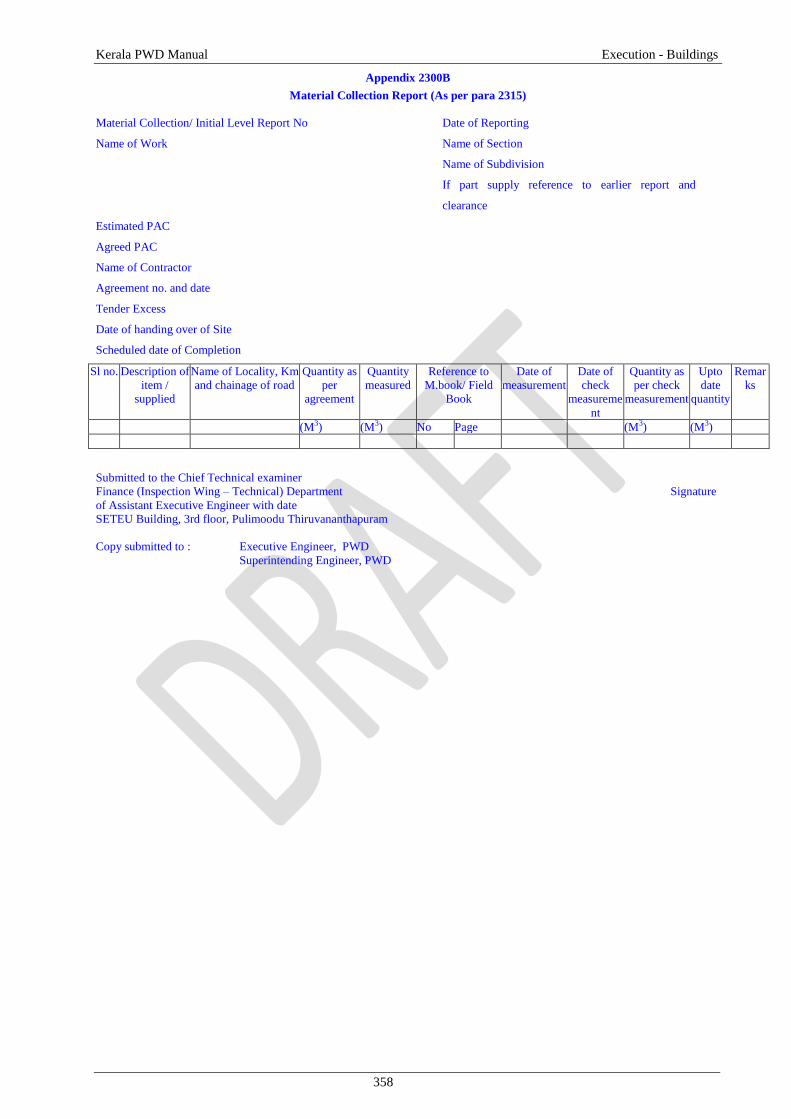
2315.Verification of Quantity by the Chief Technical Examiner:

Earth work in all works exceeds 300Cum and the quantity of any aggregate supplied for Road

work exceeds 50 cum the Assistant Executive Engineer shall report under certificate of posting to Chief

Technical Examiner in the performa given in Appendix 2300B so as to verify the reported quantity. Earth

work and usage of stacked materials can be used only after the verification or on completion of seven

working days from the date of posting. In case of urgency the Executive Engineer shall super-check the

full quantity and give sanction to proceed with the work.

Kerala PWD Manual Execution - General

328

2316.Bills and Payment

A bill is normally paid once every month or at suitable intervals according to particular stages of

execution of work as per the agreement for which the contractor shall submit the bill. The Assistant

Engineer shall then verify the bill by taking requisite measurements.

Bill preparation and Payment for the work shall be done only with of the following certificates:

The contractor has to produce the necessary certificates for compliance to Quality procedures as per

chapter on Quality control. Environment Certificate as per the chapter on Environmental aspects shall also

be produced. In case of Road and Bridge works, Road Safety Certificate as per the chapter on road safety

shall be produced.

2317.Road Machinery

Mechanization of road construction is not only necessary for speedy construction but also for

overall economy and for achieving the desired quality of the finished job. Starting from grubbing or site

clearance, the road construction machinery can be deployed at all stages of construction till completion of

the project. The requirement of appropriate machinery for excavation of different operation of road

construction is given in Appendix 2300C. The expected out put of machines is given in Appendix 2300D.

2318.Departmental Execution

If tenders are not obtained at reasonable rates, and there is no possibility of getting a better offer from the

contractors any further, the departmental execution shall be resorted to. The field officers shall prepare the

workable rate for the entire work for departmental execution and submit proposal to the concerned Chief

Engineer who shall approve the proposal and issue orders fixing the ceiling cost. This shall be intimated to

the government and availability of funds ensured and placed at the disposal of Assistant Engineer every

month according to time schedule of the work. After completion of the work, a completion report shall be

prepared. Public notification inviting quotations for supply of goods and rendering services shall be in one

or two newspapers having circulation in the district where the work is being carried out providing a

minimum gap of two weeks from the date of publication and the date of submission of Quotations, where

the estimate cost is above Rs. 10 Lakh.

Kerala PWD Manual Execution - General

329

2319. EXECUTION – ROADS

This section provides a guide to the correct construction practices and procedures for use on road

contracts. Throughout the site (the area where the works are being constructed) the contractor is

responsible for supplying all the necessary signs and other equipment to ensure the smooth and safe flow

of traffic. The construction shall be carried out in a safe and controlled manner to prevent damage to

vehicles and the general public from construction equipment, site materials and activities.

2320.General

2320.1. Key Points

Before any construction the roadway must be cleared of all vegetation and trees, including their

roots removed.

Cross sections shall be taken prior to any excavation works.

Finalize cross section of the alignment and levels prior to excavation.

All construction works must be carried out in as safe a manner as possible.

Excavated materials, if suitable, shall be used wherever possible in the works.

Provision has to be made for drainage of the temporary and permanent works.

Soil containing vegetable matter shall not be used as fill material.

Borrow pits shall not affect the stability of the road, or any other structure.

Details to be submitted for Approval from Engineer to start work are as per Appendix 4.18

2321. Setting Out

The working Bench Marks tied with the Reference Bench Mark, wherever necessary, shall be

established before commencement of the work. The working Bench Marks shall be at the rate of four per

km and also at or near all drainage structures over-bridges and underpasses. An up-to-date record of all

bench marks including approved adjustments, if any, shall be maintained by the Assistant Engineer. The

lines and levels of formation, side slopes, drainage works, carriageways and shallers shall be carefully set

out and frequently checked during construction, care being taken to ensure that correct gradients and cross

sections are obtained everywhere.

In order to facilitate the setting out of the works, the centerlines of the carriageway or highway

must be accurately established based on the investigation report (as specified in chapter 2 of section 3), in

every 30 m or less intervals in plain and rolling terrains and 20m intervals in hilly terrain and in all curve

points with marker pegs and chainage boards . On construction reaching the formation level stage, the

centerline shall be set out again to avoid any deviation from the approved centre line. No reference peg or

mark shall be moved or withdrawn and no earthwork or structural work shall commence until the centre

line has been referenced and approved by the Assistant Engineer.

2322.Public Utilities

The Assistant Engineer shall prepare drawing showing the affected services like water pipes,

sewers, oil pipelines, electric lines and posts, telephone lines, cables, gas ducts etc owned by various

authorities including Public Undertakings and Local Authorities. He shall do this by collecting necessary

details of such utilities in the site or in consultation with the concerned departments and joint inspection

wherever necessary. These drawings shall be finalized during the tender stage and utilities are to be

shifted before the commencement of the work. The improvement and up gradation of the roads are

important for the community; hence all departments/authorities using PWD land must co-operate to shift

the utilities in time.

2323.Clearing of Site:

Clearing of site by dismantling old bridges and culverts and existing pavements shall be as per section

200 of MoRTH.

2324. Excavation

This work shall consist of excavation, removal and satisfactory disposal of all materials necessary for

the construction of roadway, side drains and waterways in accordance with the lines, grades and cross-

sections shown in the drawings or as indicated by the Engineer. Excavation for road works shall conform

to the specifications of Section 300 of MoRTH. It shall include the hauling and stacking of or hauling to

sites of embankment and subgrade construction, suitable cut materials as required, as also the disposal of

Kerala PWD Manual Execution - General

330

unsuitable cut materials in specified manner, trimming and finishing of the road to specified dimensions

or as directed by the Assistant Engineer.

2324.1. Classification of Excavated Material

The excavated materials shall be classified as specified in section 301.2.1 of MORTH.

2324.2.Authority for classification

The classification of excavation shall be proposed by the Assistant Engineer and got approved by the

Assistant Executive Engineer.

2324.3.Road Formation in Cutting

Where hard strata are available, and the formation level is below existing ground level, excavation

shall be done with due consideration of the stability of slopes. Benching may be resorted to wherever

necessary and other suitable slope protection provided. In case of rocks the provisions of clause 301.3.5

and 301.6 of MoRTH shall apply.

2325.Embankment Construction

2325.1.Key Points

All fill materials must be free from vegetable matter and the material must be approved as

suitable.

The material shall be of an appropriate nature and at moisture content that permits compaction to

form a stable layer.

Generally embankments shall be constructed in 150 mm compacted layers parallel to the finished

grade of the road.

For each completed layer the density shall be checked (One test for each 1,000 square meters) by

laboratory personnel. If test results show the required density is not achieved further compaction

is necessary

Any soft areas must be rectified before further material is placed. Each earthworks layer requires

to be approved before the next layer can be started.

All embankments, subgrades, earthen shallers and miscellaneous backfills shall be constructed in

accordance with the lines, grades, and cross-sections shown on the drawings or as directed by the

Assistant Engineer. It shall follow the specification as per clause 305 of MORTH

Figure 4.1 Pavement Layers

2325.1.Sub grade

The sub grade is the layer of embankment immediately below the pavement. This may be

undisturbed local material or may be soil excavated elsewhere and placed as fill. In either case it has to be

prepared to give added strength. All subgrade material must be free of vegetable matter. The material also

needs to be of a type and moisture content that it can be compacted to form a stable layer. If the material

Kerala PWD Manual Execution - General

331

in the subgrade level is found to be unsuitable, this must be excavated and replaced with suitable material,

which shall then be compacted. The subgrade must be prepared over the full width of the embankment,

including the shallers. This is generally carried out in lengths of greater than 100 metres. In some cases to

maintain traffic, part width working may be necessary. If this is the case it is vital that the full width of the

embankment meets the subgrade material and compaction requirements. When the road is to be placed on

existing material, this shall be fully loosened to a depth of 150 mm below the subgrade level. Any lumps

shall be removed or broken up to be less than 50 mm in size. The subgrade must be compacted uniformly

by use of adequate and appropriate compaction equipment. The material shall be at moisture content close

to optimum throughout the layer so that it can be compacted to produce a dense compacted layer.

Generally the compaction shall begin at the outer edges of the embankment and by rolling in a

longitudinal direction gradually progress towards the centre so that each section receives equal

compaction.

Laboratory tests shall be performed as specified in the chapter on Quality control.

2325.2.Drainage

The surface of the embankment/subgrade at all times during construction shall be maintained at such a

cross fall (not flatter than that required for effective drainage of an earthen surface) as will shed water and

prevent ponding. For this surface drains and subgrade drains shall be provided.

2325.3. Surface drains

Drains shall follow the slope of embankment. Surface drains shall be excavated to the specified lines,

grades, levels and dimensions to the requirements of Clause 309 of MoRTH Specifications for Road and

Bridge works.

2325.4. Sub grade Drains

Sub grade drains are constructed to ensure that water in the pavement, which would weaken the

road, is allowed to drain way. Subgrade drains shall be extended to the edge of the embankment with

drains on opposite sides of the road being staggered. In case of roads with minimal longitudinal fall it is

often better to install subgrade drains longitudinally at the edge of the road pavement, see Figure 4.1

Subgrade drains shall be excavated by hand in the prepared subgrade. The excavation shall be filled with

clean sand or gravel, which contains no vegetable matter, silt or clay. The backfill must be compacted by

hand ramming and struck off level with, or slightly above, the finished subgrade level. The finished

backfill must be immediately covered with an approved separator material. The separator material is

normally specified and will be woven rot proof fabric, geo-textile membrane or perforated heavy duty

polythene sheeting. The separator material shall extend 150mm beyond the edges of the drain on all

exposed faces. Any joints in the fabric shall overlap by at least 150mm. Materials over the drain shall be

placed by hand for at least 100mm above the separator membrane prior to rolling either the pavement or

the shaller materials.

2325.5.Finishing operations

Finishing operations shall include the work of shaping and dressing the shallers /verge/road bed and

side slopes to conform to the alignment, level, cross-sections and dimensions shown on the drawings or as

directed by the Engineer. Both the upper and lower ends of the side slopes shall be rounded off to improve

appearance and to merge the embankment with the adjacent terrain. When earthwork operations have been

substantially completed, the road area shall be cleared of all debris, and ugly scars in the construction area

responsible for objectionable appearance eliminated.

2326.Sub Base

2326.1.Granular Sub Base

This work shall consist of laying and compacting well-graded material on prepared subgrade in

accordance with the Specifications. The material shall be laid in one or more layers as sub-base or lower

sub-base and upper sub-base (termed as sub-base hereinafter) as necessary according to lines, grades and

cross -sections shown on the drawings or as directed by the Assistant Engineer.

The materials to be used, construction operations, surface finish and Quality checks and opening to traffic

shall be as per the specifications of MORTH clause 401.

Kerala PWD Manual Execution - General

332

2326.2.Cement Treated Soil Sub-Base/Base

This work shall consist of laying and compacting a sub-base/base course of soil treated with cement on

prepared subgrade/sub-base, in accordance with the requirements of these Specifications and in

conformity with the lines, grades and cross-sections shown on the drawings or as directed by the

Engineer.

The materials to be used, construction operations, surface finish and Quality checks and opening to traffic

shall be as per the specifications of MORTH clause 403.

2327. Base Course (Non Bituminous)

The following are the base courses (Non Bituminous) usually provided for road works

Water Bound Macadam Sub –Base / Base

Sub Base Course: Normally consists of at least one layer of grading I or II materials.

Base course: Base course is done using Grade III material.

Crusher-Run Macadam Base

Crushed Cement Concrete Sub-Base/Base

Wet Mix Macadam Sub -Base/Base

2327.1.Water Bound Macadam Sub –Base / Base

WBM may be used as Sub Base as well as Base course and also surface course of rural roads.

This work shall consist of clean, crushed aggregates mechanically interlocked by rolling and bonding

together with screening, binding material where necessary and water laid on a properly prepared

subgrade/ sub-base/ base or existing pavement, as the case may be and finished in accordance with the

requirements of these Specifications and in close conformity with the lines, grades, cross-sections and

thickness as per approved plans or as directed by the Engineer.

It is, however, not desirable to lay water bound macadam on an existing thin black topped surface

without providing adequate drainage facility for water that would get accumulated at the interface of

existing bituminous surface and water bound macadam. The materials to be used, construction operations,

surface finish and Quality checks and opening to traffic shall be as per the specifications of MORTH

clause 404

2327.2.Crusher-Run Macadam Base

This work shall consist of furnishing, placing and compacting crushed stone aggregate sub-base

and base courses constructed in accordance with the requirements set forth in this Specification and in

conformity with the lines, grades, thicknesses and cross-sections shown on the plans or as directed by the

Engineer,

The materials to be used, construction operations, surface finish, Quality checks and opening to

traffic shall be as per the specifications of MORTH clause 410.

2327.3.Crushed Cement Concrete Sub-Base/Base

This work shall consist of breaking and crushing the damaged cement concrete slabs and

recompacting the same as sub-base/base course in one or more layers. Where specified, it shall also

include treating the surface of the top layer with a penetration coat of bitumen.

The materials to be used, construction operations, surface finish and Quality checks and opening to traffic

shall be as per the specifications of MORTH clause 405.

2327.4.Wet Mix Macadam Sub -Base/Base

This work shall consist of laying and compacting clean, crushed, graded aggregate and granular

material, premixed with water, to a dense mass on a prepared subgrade/sub -base/base or existing

pavement as the case may be The material shall be laid in one or more layers as necessary to lines, grades

and cross -sections shown on the approved drawings or as directed by the Engineer. The thickness of a

single compacted Wet Mix Macadam layer shall not be less than 75 mm. When vibrating or other

approved types of compacting equipment arc used, the compacted depth of a single layer of the sub-base

course may be increased to 200 mm upon approval of the Engineer.

The materials to be used, construction operations, surface finish and Quality checks and opening to

traffic shall be as per the specifications of MORTH clause 406.

Kerala PWD Manual Execution - General

333

2328. Bituminous Base and Surface Courses

2328.1.General

Bituminous pavement courses shall be in accordance with Specifications of MoRTH clause 501. The use

of machinery and equipment mentioned in various Clauses of these Specifications is mandatory, and for

more details Manual for Construction and Supervision of Bituminous Works by MoRT&H may be

referred.

2328.2. Laying Trials

Once the plant trials have been successfully completed as per MoRTH, and approved, the Contractor shall

carry out laying trials, to demonstrate that the proposed mix can be successfully laid, and compacted all in

accordance with the MoRTH Specifications. The laying trial shall be carried out as per MoRTH

Specifications for road and Bridge works.

2328.2.1.Key Points

Samples of the material along with laboratory test results shall be submitted to the Engineer at

least 14 days in advance of a proposed material’s use. If approved, the contractor shall then carry

out trial mixes. This shall also be tested and approved. No dense bituminous surfacing can occur

until both the job mix formula and the trial sections have been approved.

Thereafter all asphalt work is required to follow the approved Job Mix formula and the procedures

established by the approved trials.

The surface upon which the bitumen or bituminous mixture is to be placed must be thoroughly

cleaned immediately before the bitumen or mixture is placed.

Bituminous materials shall be placed only when the surface is dry, when rain does not appear

imminent and when the prepared road bed is in a satisfactory condition.

The entire surface to be primed must be covered evenly. The distributor shall be cleaned and

calibrated to ensure the required rate of spray is achieved. Depending on the nature of the surface

to be primed a light application of water just prior to priming may be beneficial to aid penetration

of the bituminous material.

No bituminous mixtures shall be placed until the prime coat has dried.

Tack coat may need to be applied to make the road surface sticky prior to the bituminous

carpeting layer being placed.

For Primer Seals and Bitumen Surface Treatments the aggregate must be spread and rolled into

bitumen immediately after spraying, preferably rolling shall be by multi tyre rollers.

Each day dense bituminous surfacing is laid, three Marshall specimens shall be prepared and

tested as ASTM D 2041

Samples to be collected from either the plant or the laid mat, as directed by the Engineer. Samples

shall also be taken each day to determine the mix composition (Extraction of bitumen test and

grading,

All equipment proposed to be used by the Contractor are in good condition and operated by

competent and experienced operators

Dense bituminous surfacing must be thoroughly compacted as soon as the material will support

the roller without undue displacement or cracking. Excess use of water on the roller drums is to be

avoided as this cools the asphalt mat.

The surface of the mixture after compaction must be close and tight, and free from dragging

cracks. Any mixture that is defective shall be removed and replaced with fresh hot material, which

shall be compacted immediately.

After final rolling, samples shall be cut from areas of bituminous surfacing for density and

thickness at specified intervals. Where samples have been taken, fresh material must be placed

and thoroughly compacted.

2328.2.2. Surface Preparation: Prime coat shall be provided as per Clause 502 and tack coat as per

clause 503 of MoRTH specifications.

2329. Base Course (Bituminous)

The different types of bituminous base course are as follows

Bituminous Macadam

Bituminous Penetration Macadam

Kerala PWD Manual Execution - General

334

Built-Up Spray Grout

Dense Graded Bituminous Macadam

Sand Asphalt Base course

2329.1. Bituminous Macadam

This work shall consist of construction in a single course having 50mm to 100mm thickness or in

multiple courses of compacted crushed aggregates premixed with a bituminous binder on a previously

prepared base to the requirements of these Specifications. Bituminous macadam is more open graded than

the dense graded bituminous materials.

The materials to be used, construction operations, surface finish and Quality checks and opening to traffic

shall be as per the specifications of MORTH clause 504.

2329.2. Bituminous Penetration Macadam

A penetration Macadam is a compacted layer of coarse aggregates into which bituminous binder

is introduced. The binder penetrates in to the layer through the voids and binds the stone aggregates. A

layer of small aggregates, called key aggregates , is spread on the surface and rolled so as to fill in the

surface voids in the coarse aggregate layer. A Seal coat is provided to make the surface more impervious

to water. This type is commonly used in remote areas where it is difficult to transport mixing and laying

equipment. It can also be used as a temporary emergency material to repair a pavement damaged by rains

and floods.

The materials to be used, construction operations, surface finish and Quality checks and opening to traffic

shall be as per the specifications of MORTH clause 505.

2329.3. Built-Up Spray Grout

This work shall consist of a two-layer composite construction of compacted crushed coarse

aggregates with application of bituminous binder after each layer, and with key aggregates placed on top

of the second layer, in accordance with the Specifications of MoRTH, to serve as a base course and in

conformity with the lines, grades and cross-sections shown on the drawings or as directed by the

Engineer. The thickness of the course shall be 75 mm. Built-up spray grout shall be used in a single

course in a pavement structure.

The materials to be used, construction operations, surface finish and Quality checks and opening to traffic

shall be as per the specifications of MORTH clause 506.

2329.4.Dense graded Bituminous Macadam

It may be used as base/binder and profile corrective courses. Apart from Bituminous Macadam,

the only difference is being that the stone aggregates are more closely graded. As a result, the resultant

mixture is more dense. DBM is also intended for use as road base material. This work shall consist of

construction in a single or multiple layers of DBM on a previously prepared base or sub-base. The

thickness of a single layer shall be 50mm to 100mm.

The materials to be used, construction operations, surface finish and Quality checks shall and opening to

traffic be as per the specifications of MORTH clause 507.

2329.5. Sand Asphalt Base Course

This work shall consist of a base course composed of a mixture of sand, mineral filler where

required and bituminous binder, placed and compacted upon a prepared and accepted subgrade in

accordance with the Specifications of Clause 520 of MoRTH. The materials to be used, construction

operations, surface finish and Quality checks and opening to traffic shall also follow the same.

This is used in special situations when quality coarse aggregates are not available within economical leads

and/or water needed for conventional base course not being readily available, as in desert areas. 50mm to

100mm.

2329.6.Surface (wearing) Course

The following are the surface (wearing) courses usually adopted.

Semi dense Bituminous Concrete (SDBC)

Bituminous Concrete (BC)

Kerala PWD Manual Execution - General

335

Surface Dressing

Open grade premix carpet

a. Open grade premix carpet using Penetration Bitumen or Cutback.

b. Open grade premix carpet using cationic bitumen emulsion

Mastic Asphalt

Close graded/ Mixed Seal Surfacing (MSS)

2329.7. Semi dense Bituminous Concrete

This clause specifies the construction of Semi Dense Bituminous Concrete, for use in

wearing/binder and profile corrective courses. This work shall consist of construction in a single or

multiple layers of semi dense bituminous concrete on a previously prepared bituminous bound surface. A

single layer shall be 25mm to 100mm in thickness.

The materials to be used, construction operations, surface finish and Quality checks and opening to traffic

shall be as per the specifications of MORTH clause 508.

2329.8. Bituminous Concrete

This clause specifies the construction of Bituminous Concrete, for use in wearing (also used as

profile corrective courses) especially for heavily trafficked highways. This work shall consist of

construction in a single layer (25mm to 100mm in thickness) of bituminous concrete on a previously

prepared bituminous bound surface.

The materials to be used, construction operations, surface finish and Quality checks and opening to traffic

shall be as per the specifications of MORTH clause 509.

2329.9 Surface Dressing

This work shall consist of the application of one coat or two coats of surface dressing, each coat

consisting of a layer of bituminous binder sprayed on a previously prepared base, followed by a cover of

stone chips rolled in to form a wearing course to the requirements of these Specifications. Surface

Dressing is used in the case of relatively lightly trafficked roads over gravel or other untreated road bases.

It shall be noted that surface dressing is a thin treatment and does not enhance the structural strength of

the pavement. If the existing road is full of irregularities and undulations, it does nothing to improve

riding quality. Design of Surface Dressing may be referred to in the Manual for Construction and

Supervision of Bituminous Works.

The materials to be used, construction operations, surface finish and Quality checks and opening to traffic

shall be as per the specifications of MORTH clause 510.

2329.10.Open grade premix carpet

2329.10.1.Open-graded Premix Surfacing using Penetration Bitumen or Cutback.

This work shall consist of the preparation, laying and compaction of an open-graded premix

surfacing material of 20 mm thickness composed of small-sized aggregate premixed with a bituminous

binder on a previously prepared base, in accordance with the requirements of these Specifications, to

serve as a wearing course.

The materials to be used, construction operations, surface finish and Quality checks and opening to traffic

shall be as per the specifications of MORTH clause 511.1.

2329.10.2.Open graded premix surfacing using cationic bitumen emulsion

This work shall consist of the preparation, laying and compaction of an open graded premix

surfacing of 20 mm thickness composed of small-sized aggregate premixed with a cationic bitumen

emulsion on a previously prepared surface, in accordance with the requirements of the relevant

Specifications of MoRTH, to serve as a wearing course.

The materials to be used, construction operations, surface finish and Quality checks and opening to traffic

shall be as per the specifications of MORTH clause 511.2.

2329.11. Mixed Seal Surfacing

This work shall consist of the preparation, laying and compaction of a close-graded premix

surfacing material of 20 mm thickness composed of graded aggregates premixed with a bituminous binder

on a previously prepared surface, in accordance with the requirements of these Specifications, to serve as

Kerala PWD Manual Execution - General

336

a wearing course. Close graded premix surfacing shall be of Type A or Type B as specified in the

Contract documents.

The materials to be used, construction operations, surface finish and Quality checks and opening to traffic

shall be as per the specifications of MORTH clause 512.

2329.12. Mastic Asphalt

This work shall consist of constructing a single layer of mastic asphalt wearing course for road

pavements and bridge decks. Mastic asphalt is an intimate homogeneous mixture of selected well graded

aggregates, filler and bitumen in such proportions as to yield a plastic and void less mass, which when

applied hot can be trowelled and floated to form a very dense impermeable surfacing. Its consistency is

such that it flows like a viscous fluid at temperatures of around 1750 C to 210

0 C but, on cooling to normal

temperatures, it solidifies in to a dense mass. Thus its construction requires no compacting effort. Because

of its superior properties, it is used as a wearing course material for heavy duty pavements, city streets

carrying high volume of traffic, bus stops where heavy tangential forces are expected, junctions where

cornering stresses are predominant.

The materials to be used, construction operations, surface finish and Quality checks and opening to traffic

shall be as per the specifications of MORTH clause 515.

2329.13. Seal Coat

This work shall consist of the application of a seal coat for sealing the voids in a bituminous surface

laid to the specified levels, grade and cross fall (camber). Seal coat shall be of either of the two types

specified below:

Liquid seal coat comprising of an application of a layer of bituminous binder followed by a cover

of stone chips.

Premixed seal coat comprising of a thin application of fine aggregate premixed with bituminous

binder.

The materials to be used, construction operations, surface finish and Quality checks and opening to traffic

shall be as per the specifications of MORTH 513.

2329.14. Bituminous Cold Mix (Including Gravel Emulsion)

Bituminous Cold Mix consists of a mixture of unheated mineral aggregate and emulsified or cutback

bitumen. This Specification deals only with plant mix (as opposed to mixed- in-place). Bituminous cold

mixes are used in situations where hot mix plants are not readily available, including for work in remote

areas and maintenance operations. Two types of mix are considered, namely,

Designed Cold Mix

Recipe Cold Mix.

The Design Mix procedure shall be used unless the Engineer specifically approves the Recipe Mix

procedure.

The materials to be used, construction operations, surface finish and Quality checks and opening

to traffic shall be as per the specifications of MORTH 519.

2330.Concrete Pavement

2330.1. Semi-rigid Pavement Construction

Semi- rigid pavements are a concrete sub base having a wearing course over it. In case of rural roads the

wearing coarse have be a thin bituminous surface. Semi-rigid pavements are also used as a Sub base for

making cement concrete pavement. Generally, the following types are used for Semi-rigid pavement

construction.

Dry Lean Cement Concrete. (DLC)

Cement Fly Ash Bound Macadam

Lime Fly Ash Concrete

Lime Fly Ash Bound Macadam

However, Dry Lean Cement Concrete (DLC) is most commonly adopted.

Kerala PWD Manual Execution - General

337

12Dry 2330.2.Lean Cement Concrete (DLC)

The work shall consist of construction of dry lean concrete subbase for cement concrete pavement in

accordance with the requirements of the Specifications and in conformity with the lines, grades and cross-

sections shown on the drawings.

The materials to be used, construction operations, surface finish and Quality checks and opening to traffic

shall be as per the specifications of MORTH 601.

2330.3.Rolled Cement concrete Base

The work shall consist of construction of rolled concrete base course for cement concrete

pavement in accordance with the requirements of these Specifications and in conformity with the lines,

grades and cross sections shown on the drawings.

The materials to be used, construction operations, surface finish and Quality checks and opening to traffic

shall be as per the specifications of MORTH 603.

2330.4.Cement Concrete Pavement

The work shall consist of construction of unreinforced, dowel jointed, plain cement concrete

pavement in accordance with the requirements of the Specifications and in conformity with the lines,

grades and cross sections shown on the drawings.

The materials to be used, construction operations, surface finish and Quality checks and opening to traffic

shall be as per the specifications of MORTH 602.

2331.Shallers

2331.1. General

Shaller gives adequate side support to the pavement and also drains off surface water from the

carriageway to the roadside drain. The work shall consist of constructing shaller on either side of the

pavement in accordance with the requirements of these Specifications and in conformity with the lines,

grades and cross-sections shown on the drawings.

Shaller may be of selected earth/ granular material/ paved conforming to the requirements of MoRT&H

Clause 305/407. Paved shallers shall consist of sub-base, base and surfacing courses, as shown in the

drawings and materials for the same shall conform to relevant Specifications of the corresponding items.

Where paved or hard shallers are not provided, the pavement shall be provided with brick/stone block

edgings as shown in the drawings. The bricks shall conform to Clause 1003 of these Specifications. Stone

blocks shall conform to Clause 1004 of these Specifications and shall be of size 225 mm x 110 mm x 75

mm.

2331.2.Shoulder width

Width of the shoulder shall vary from 1 m to 2.5 m be as shown on the drawings or as directed by the

Assistant Engineer.

2331.2.1. Construction Method

The sequence of operations shall be such that the construction of paved shaller is done in layers

each matching the thickness of adjoining pavement layer. Only after a layer of pavement and

corresponding layers in paved and earth shaller portion have been laid and compacted, the construction of

next layer of pavement and shaller shall be taken up.

Where the materials in adjacent layers are different, these shall be laid together and the pavement layer

shall be compacted first. The corresponding layer in paved shaller portion shall be compacted thereafter,

which shall be followed by compaction of earth shaller layer. The adjacent layers having same material

shall be laid and compacted together.

During all stages of shaller (earthen/ hard/ paved) construction, the required crossfall shall be maintained

to drain off surface water.

Kerala PWD Manual Execution - General

338

2331.3. Culverts

Culverts are mainly of two types, Pipe Culverts and Slab Culverts. The width of culvert shall be

equal to the formation width of the road. It shall be generally situated on the straight alignment of the

road. If the road has a gradient the same shall be maintained for deck slab of the culvert.

2331.3.1. Pipe Culverts: NP 4 pipes for national highways conforming to IS 458:1988 shall be used.

Bedding: The bedding must be even and uniform, projecting rock faces and boulders must be removed

before forming the bedding. The thickness of bedding layer shall be minimum 75 mm. The bedding

material shall be well graded sand or granular material passing 75 mm sieve.

For heights of fill greater than 4 m, continuous concrete cradle bedding may be used. The mix shall not be

leaner than M150 concrete and the pipes shall be layed in position before the concrete has set.

Laying: Start Laying from the outlet and proceed towards the inlet ensuring the specified lines and grade.

The minimum longitudinal slope shall be 1 in 1000.

Where two or more lines of pipes are to be laid adjacent to each other, they shall be separated by a

distance equal to at least half the diameter of the pipe subject to a minimum of 450 mm. Ensure that the

pipe has a cushion of at least 0.60 m excluding crust thickness at the top.

Section 2900 of MoRTH specifications shal be referred for further details.

2331.3.2.RCC Slab Culverts:

Depending on the scour characteristics of the bed material, open foundations with or without

erosion proof bed flooring is generally adopted. In general, concrete footing shall rest over good stratum

at a depth of about 1.5m below the lowest bed level. Bed flooring where provided shall consist of stone

pitching set in cement mortar 1:3 or two layers of brick on edge set in cement mortar 1:3. These shall be

layed over 150 mm thick foundation concrete M15.

2331.3.3.RCC Box culverts

These are economical in such cases where either the depth of foundation is more than 4 m below bed

level or where the total embankment is very high and are suitable for a situation where the catchment area

is more than 40 hectares. Box section of height less than 2m X 2m is not practicable to implement.

2332.Dimensions of abutment and wing wall:

Dimensions of abutment for RCC Slab Culvert

Span 1m to 4 m 5m to 6 m

H 2 3 4 2 3 4

b1 0.2 0.3 0.4 0.2 0.3 0.4

b2 0.7 1.1 1.4 0.6 1 1.4

b3 0.3 0.3 0.3 0.4 0.4 0.4

b4 - 0.2 0.5 - 0.2 0.6

B1 1.5 2.0 2.4 1.5 2.0 2.5

B2 2.7 3.6 4.6 2.7 3.6 4.9

Dimensions of wing wall

Span upto 2 m 3 m 4 m 5 m 6m

H 2 3 4 2 3 4 2 3 4 2 3 4 2 3 4

b1 0.23 0.33 0.43 0.24 0.34 0.44 0.24 0.34 0.44 0.25 0.35 0.45 0.25 0.35 0.45

b2 0.57 0.82 1.07 0.59 0.84 1.09 0.6 0.85 1.10 0.62 0.87 1.13 0.63 0.88 1.13

B1 1.3 1.65 2.0 1.33 1.68 2.03 1.34 1.69 2.04 1.37 1.72 2.08 1.38 1.72 2.08

B2 2.1 2.45 2.8 2.13 2.48 2.83 2.14 2.49 2.84 2.17 2.52 2.88 2.18 2.53 2.88

Kerala PWD Manual Execution - General

339

Figure 4.2 Abutment and wing wall section for height more than 4.5m

The following points are to be followed for construction of culverts.

1. The design shall be based on 2lane IRC Class A loading.

2. The length of wing walls shall be sufficient to eliminate any tendency of the embankment slope to

slip into the stream.

3. Construction joint between abutment and wing wall shall be provided to avoid overstressing at the

junction due to differential settlement.

4. The bearing shall be of reinforced bitumen laminated Kraft paper conforming to IS 1938. While

concreting the slabs, care shall be taken to prevent the bearing material from being displaced.

5. All space between foundation, masonry or concrete and the sides of excavation shall be refilled to

the original surface in layers not exceeding 150 mm compacted thickness.

6. The backfill material around the structure shall be of granular type having plasticity index and

liquid limit not exceeding 20 and 40 respectively. The fill material shall be deposited in horizontal

layers not exceeding 200 mm compacted thickness.

7. If the height and abutment and return over bed level is more than 2 m weep hole shall be provided

150 mm above low water level or ground level which ever is higher. In case of concrete/ masonry,

weep holes of 150 mm dia or 80 X 150 mm size in 1:20 slope shall be provided at 1 metre interval

both horizontally and vertically. Refer IRC 40

b2 b3 b1

0.3

b4 b4

0.4

0.4

0.2 0.2

0.4

0.2 0.2

B1

B2

BED LEVEL

0.3

H

b3

Section of Abutment

b2 b1

0.3

0.4

0.4

B1

B2

BED LEVEL

Section of Wing Wall

0.4

0.4 0.2

Road Surface End Pillar

Premix Carpet Wearing Coat

150 mm WBM

Parapet

150 mm Boulder Cushion

CC Bed Block

Masonry / CC Abutment

Masonry / CC Foundation

CC 1:4:8 , 20mm

Slope 1: 3

CC/ RR Packing

H

Figure 4.3 Typical Details of Abutment and wing wall section for height upto

4.5m

1500mm 3000mm 3000mm

40 30

10

10

10

Deck Slab 210 mm

Construction Joint

Kerala PWD Manual Execution - General

340

8. Water Spout shall be provided for large span culverts. For 5 and 6 m span, one water spout of 100

mm diameter shall be provided in the centre of slab on either side of the deck.

9. All culverts shall be numbered on the end pillars as per IRC SP 20 with year of construction.

10. In case of stone masonry, coarse rubble masonry is stipulated.

11. Face stones shall be hammer dressed on all beds and joints so as to give them approximately

rectangular shapes.

12. The hearting or interior filling of the wall shall consist of flat bedded stone carefully laid on their

proper beds in mortar. While the use of chips shall be restricted to the filling of interstices between

the adjacent stones in hearting and these shall not exceed 15 % of the quantity of masonry.

13. Bond stones or headers shall be at 1.5 m or 1.8 m apart clear in every course. The headers shall

overlap at least by 150 mm

14. Face stone shall tail into the work for not less than their heights and at least one third of the stones

shall tail into the work for a length not less than twice the height.

15. The face joint shall not be more than 20 mm thick.

2333.Causeways and Submersible Bridges.

A causeway is a small submersible structure, which allows flood to pass over it.

2333.1.Flush causeway: it is a paved dip built to cross a shallow water course. The top level shall be at

the same level as that of the bed of the water course.

2333.2. A low level or vented causeway: this is a structure provided with a few openings comprising of

pipes, small span slabs or small arches etc. with a raised road top level to a moderate height upto 1.5 m

height.

2333.3. A high-level causeway: This is a submersible structure provided with larger openings comprising

of a simply supported /continuous RCC slab or multiple arches or boxes and a raised road top level to a

reasonable height 1.5 m to 3 m. The RCC Slab may be supported over a series of short piers (Masonry/ CC)

To avoid the heading up of water on the upstream side which results in producing high velocities leading

to structural failure and out flanking, the top level of the causeway shall be kept as low as possible. The

water way provided in the causeway shall not be less than 30 % of the area of the stream, measured

between the stream bed level and the proposed top level of the road.

The details for culvert and causeway design shall be referred to in IRC SP 20-2002.

2334.Side drains

Side drain must be provided to collect surface water from the roadway and lead to an out let. It

also acts as an outlet for the subsurface drains thereby protecting the base course of the roadway structure

from getting saturated/ lose its load bearing capacity. Side drains are designed for open channel flow and

generally provided on both sides of the road. Road drains in hilly terrain are constructed to parabolic,

trapezoidal, triangular, V-shaped, Kerb and channel or U- shaped cross sections.

IRC SP 20 and IRC 42 may be referred for details and design of drains.

2335.Geosynthetics

This specification covers the various applications of Geosynthetic materials in road and bridge

works including supplying and laying as per special provisions.

Geosynthetics includes,

(i) Geotextile: Any permeable textile natural or Synthetic, used with foundation, soil, rock, earth, or any

other geotechnical engineering related material. In the present chapter, it is related to synthetic

material only.

(ii) Geogrid: A deformed or non-deformed grid of polymeric material used primarily for reinforcement

purposes with foundation, soil, rock, earth, or any other geolechnical engineering related material.

(iii) Geonets : These are net made of polymeric material used for drainage of foundation, soil, rock, earth

or any other geotechnical engineering related material.

(iv) Geomembrane : An essentially impermeable membrane of polymeric material used with foundation,

soil, rock, earth or my other geotechnical engineering related material, to control fluid migration.-

(v) Geocomposite : A manufactured material using geoiexliles, geogrids, geonet and/ or geomembrane in

laminated or composite form,"

The details on specifications, quality and laying of geosynthetics are given in Section 700 of MoRTH.

Kerala PWD Manual Execution - General

341

2336.Execution – Bridges

2336.1.General

Before start of construction work, the procedure mentioned in section 2300 must be followed and care

must be taken to ensure that the following documents are available at site.

1. Sanction letter and technical note if any

2. Bill of Quantities

3. Copy of contract document

4. Copy of approved set of plans, estimates and detailed working drawings

5. Standards, specifications, guidelines, codes of practices etc., according to which the work must be

executed as per contract

6. Survey, investigation and subsoil test reports

2337. Excavation

Before starting excavation, it is necessary that initial site levels are taken. Protective works, if any,

shall be completed before monsoon so that foundations do not get undermined. Excavations for laying

foundations shall be carried out in accordance with Section 300 of MoRTH Specification for Road and

Bridge works. The last 300 mm of excavation shall be done just before laying of lean concrete below

foundation.

Where there is any doubt regarding the bearing capacity or suitability of the foundation soil the matter

shall be reported to the Executive Engineer. In the case of small works up to TS power of Executive

Engineer, if any variation on the width, depth and type of foundation is found necessary the Assistant

Executive Engineer himself may decide the matter after reporting to the authority sanctioning the

estimate.

Load tests shall be conducted in the foundation soil if found necessary. If the contractor has over

excavated the foundation, he shall not be allowed to refill this with earth but, the additional excavation

shall be filled up by concrete. No extra cost is payable to the contractor on this account. In some cases, it

may be possible to reduce the depth or width of foundation due to existence of harder type of soil or rock

in particular localities but the Assistant Executive Engineer may decide on the alteration necessary and

instruct the contractor accordingly. A report shall be sent to the Executive Engineer clearly indicating the

change effected and the reasons therefore.

The useful materials obtained from excavation like moorum sand stone etc. shall be stacked separately

and properly measured and accounted for. It shall be reused for backfilling of foundations and other useful

works. All spaces excavated and not occupied by the foundation shall be refilled upto surrounding level

in accordance with section 300 MoRTH Specification for Road and Bridge works. All safety measures

shall be observed at site to avoid accidents. Unauthorized entries to site of work shall be prohibited. The

contractor shall obtain proper license for explosives whenever these are to be stored.

The excavation for foundation shall be checked and got approved by the Executive Engineer

2338. Concreting

All the materials used in concreting must be tested for relative properties before hand.

2338.1. Key Points

The minimum cement content is based on 20 mm aggregate.

For 40 mm and larger sized aggregates, cement content may be reduced suitably, but the reduction

shall not be more than 10%

For underwater concreting, the cement content shall be increased by 10 %.

Prior to start of construction, the contractor shall design the mix and submit to the Executive

Engineer for approval of the mix, proportions of materials, including admixtures used.

Trial mixes: Test cubes shall be taken, from trial mixes. For each mix, set of six cubes shall be

made from each of three consecutive batches. Three cubes from each set of mix shall be tested at

an age of 28 days and three at an earlier date (7 days) approved by the Executive Engineer. The

cubes shall be made, cured, stored, transported and tested in conformity with the MoRTH

specifications.

The average strength of the nine cubes at 28 days shall exceed the specified characteristic

strength.

Kerala PWD Manual Execution - General

342

Concrete shall be mixed either in a concrete mixer or in a batching and mixing plant approved by

the Executive Engineer. Hand mixing shall not be permitted.

Mixers, which have been out of use for more than 30 minutes, shall be thoroughly cleaned before

putting in a new batch.

The first batch of concrete from the mixer shall contain only two thirds of the normal quantity of

coarse aggregate.

The compacted thickness of each layer shall not be more than 0.45 m when internal vibrators are

used and shall not exceed 0.3 m in all other cases.

Do not allow dropping of concrete from a height exceeding 2 m.

When concreting is to be received on a surface, which has hardened, it shall be roughened, swept

clean, wetted and covered with a 13 mm thick mortar layer composed of cement and sand in the

same ratio as in the concrete mix.

Do not apply vibration through the reinforcement.

Keep the compacted concrete continuously wet for a period not less than 14 days

Transporting, placing and compaction of Concrete shall be as per clause 1709 of MoRTH Specification

for Road and Bridge works. For formwork and staging clause 1500 of MoRTH Specification for Road and

Bridge works shall be followed. The contractor shall furnish the design and drawings of complete

formwork as well as their supports for approval of the Assistant Executive engineer before any erection is

taken up. Metal/ laminated board formwork shall preferably be used for achieving good finish. The

formwork shall be robust and strong and the joints shall be leak proof. The formwork shall be coated with

an approved release agent that will effectively prevent sticking and will not stain the concrete sides. The

formwork shall be inspected and approved by Assistant Executive Engineer before concreting is done.

The requisite properties for structural steel shall be as per clause 1009 of MoRTH Specification for Road

and Bridge works and its placement shall conform to clause 1600 of MoRTH Specification for Road and

Bridge works. This includes protection of reinforcement, bar splicing and bending of reinforcement. The

size (Maximum nominal) of coarse aggregates for concrete to be used shall be as given in Table 123.4

Table 123.4 Maximum nominal size of Coarse aggregates

Sl

no:

Components Maximum nominal size of Coarse

aggregates

1 RCC Well kerb 20

2 RCC/ PCC Well steining 40

3 Well cap or pile cap, solid type piers and abutment 20

4 RCC work in Girders, slabs, wearing coat, curb

approach slab, hollow piers and abutments, piers.

20

5 Pre stressed concrete (PSC) work 20

6 Any other item. As specified by the Executive Engineer

The time of removal of formwork and staging shall be as per Table 4.3.2.

Table 4.3.2 Time of Removal of Formwork

a)

Walls, piers, abutments, columns and vertical faces of

structural members

12 – 48 hours as may be decided by the

Assistant Executive Engineer

b) Soffits of slab (with props left under) 3 days

c) Props (Left under Slabs) 14 days

d) Soffits of Girders (With props left under 7 days

e) Props (left under Girders) 21 days

2339. Foundations

2339.1. Open foundation:

The plan dimensions of the foundation shall be set out at the bottom of foundation trench and

checked with respect to original reference line and axis. It shall be ensured that at no point the bearing

surface is higher than the founding level shown on the drawing.

Open foundation shall be constructed in dry conditions and the contractor shall provide for adequate

dewatering arrangements to the satisfaction of the Assistant Executive Engineer. Measures such as bailing

out, pumping, constructing diversion channels etc. shall be taken to keep the foundation trenches dry and

Kerala PWD Manual Execution - General

343

to protect the green concrete against damage. Where the bearing surface is earth, a layer of M15 concrete

shall be provided below foundation concrete. The thickness of lean concrete layer shall be 100 mm

minimum unless otherwise specified. All spaces excavated and not occupied by the foundation shall be

refilled and compacted with earth up to the surface of surrounding ground. In case of excavation in rock,

the annular space around foundation shall be filled with M 15 concrete up to the top of rock.

The construction procedure shall conform to provisions contained in Section 2100 of MoRTH

Specification for Road and Bridge works.

2339.2. Well foundation:

This work consists of construction of well foundation, taking it down to the founding level through all

kinds of sub-strata, plugging the bottom, filling the inside of the well, plugging the top and providing a

well cap in accordance with the details shown on the drawing and as per the specifications of MoRTH

Specification for Road and Bridge works section 1200.

Key points:

Fix up reference points, away from the zone of blowups/ settlements resulting from well sinking

and mark centre lines of the individual wells in longitudinal and transverse directions accurately.

Benchmark and reference points shall be checked regularly from permanent points fixed at site.

Cutting edge shall be laid on dry ground / sand island.

Sand island to be protected against scour until the sinking is done to a safe level.

Floating caisson of steel can be adopted when construction of Sand Island is not feasible.

Use steel formwork for well curb

Concreting in the well curb shall be done in one continuous operation.

Steining shall be cast only after sinking the curb to some extent so that it becomes stable.

The steining shall be built in one straight line from bottom to top.

The height of the steining shall be calibrated by marking on outer faces in longitudinal and

transverse directions (4 sides) with every metre mark in paint. Zero shall start from bottom of the

cutting edge.

For sinking, material be excavated uniformly all round the dredge hole

De-watering shall not be permitted as a means for sinking.

A detailed statement with regard to the progress of well sinking shall be maintained at site as per

Appendix 2300F

If a tilt occurs, further steining has to be carried out, with the axis of the extended steining

following the axis of the well already sunk. Tilts shall be corrected as soon as it occurs.

Sinking history of well including tilt and shift, kentledge, dewatering, blasting done during

sinking shall be maintained in the format given in Appendix-2300G.

The depth of sump below the level of cutting edge shall be generally limited to one-sixth of the

outer diameter/ least lateral dimensions of well in place. Normally, the depth of sump shall not

exceed 3m unless otherwise specifically permitted by the Engineer.

Bottom plugging shall be done with the help of tremie pipe. Additional 10 per cent cement shall

be provided in the concrete for bottom plug.

A record of the method of sinking adopted, bottlenecks encountered etc. may be kept as per

proforma given in Appendix-2300H.

2339.3. Pile Foundation

Sub-surface investigation shall be carried out by in-situ pile tests. At least one bore- hole for every

foundation of the bridge shall be executed. Depth of boring shall not be less than

1.5 times estimated length of pile in soil but not less than 15 m beyond the probable length of pile

15 times diameter of pile in weak/jointed rock but minimum 15 m in such rock

4 times diameter of pile in sound, hard rock but minimum 3 m in such rock

2339.3.1. Type of piles

The piles may be of reinforced concrete, pre stressed concrete, steel or timber. The piles may be of solid

or hollow sections or steel cased piles filled with concrete. Concrete piles may be driven cast-in- situ or

pre-cast or bored cast- in-situ or pre-cast piles driven into preformed bores. The shape of piles may be

circular, square, hexagonal, octagonal, "H" or "I" Section.

Construction of pile foundations shall be as per the MoRTH Specification for Road and Bridge works

clause 1100 and IS: 2911. The construction of pile foundations requires a careful choice of the piling

Kerala PWD Manual Execution - General

344

system depending upon sub-soil conditions and loading characteristics and type of structure. The method

of installing the piles, including details of the equipment shall be submitted by the Contractor and got

approved by the Executive Engineer

2339.3.1.1. Key points:

(i) Test piles

Test piles that are to become a part of the completed structure shall be installed with the same

type of equipment that is proposed to be used for piling in the actual structure.

Test piles, which, are not to be incorporated in the completed structure, shall be removed to at

least 600 mm below the proposed soffit level of pile cap and the remaining hole shall be

backfilled with earth or other suitable material.

(ii) Pre-cast concrete piles

For pre cast piles , concrete shall be placed continuously until the completion of each pile, the

length of pile shall not normally exceed 25 metres.

Pre-cast concrete piles shall be lifted by means of a suitable bridle or sling attached to the pile but

normally at points not more than 3 metres from the ends of the piles

Pre-cast concrete piles cured with water shall not be driven for at least 28 days after casting ( 10

days with rapid hardening cement )

Detailed procedure for construction and driving of pre-cast pile are given in the MoRTH Specification for

Road and Bridge works clause 1106

(iii) Cast-in-situ concrete piles

Cast-in-situ concrete piles may be either installed by making a bore into the ground by removal of

material or by driving a metal casing with a shoe at the tip and displacing the material laterally.

Cast- in-situ concrete piles may be cast in metal shells, which may remain permanently in place.

The reinforcement cages must be prepared in advance and adjustment to the length done

depending on site requirements.

This cage shall be lowered just prior to concreting and completed without interruption.

In case of liners being withdrawn, sufficient head of concrete has to be provided to prevent the

entry of ground water or reduction of cross section (necking of the pile).

A minimum of 2.0 m length of top of bore shall invariably be provided with casing to ensure

against loose soil falling into the bore.

If the concrete is placed inside pre-cast concrete tubes or consists of pre-cast sections, these shall

be free from cracks or other damage before being installed.

Specific requirements of cast- in-situ driven piles shall be as per Clauses 1100 of MoRTH Specification

for Road and Bridge works.

The equipments used for pile driving and the detailed procedures shall be as per Clauses 1110 & 1111 of

MoRTH Specification for Road and Bridge works.

2340. Sub Structure

The construction procedure shall conform to provisions contained in Section 2200 of MoRTH

Specifications for Road and Bridge Works.

2340.1. Piers and Abutments

In case of concrete piers, the number of horizontal construction joints shall be kept minimum.

Construction joints shall be avoided in splash zones.

No vertical construction joint shall be provided.

In case of tall piers and abutments, use of slip form shall be preferred.

The surface of foundation/well cap/pile cap shall be scrapped with wire brush and all loose

materials removed.

In case reinforcing bars projecting from foundations are coated with cement slurry, tapping,

hammering or wire brushing shall remove the same.

Before commencing masonry or concrete work, the surface shall be thoroughly wetted.

In case of solid (non-spill through type) abutments, weep holes as shown on the drawings shall be

provided.

The surface finish shall be smooth, except the earth face of abutments, which shall be rough,

finished.

Kerala PWD Manual Execution - General

345

In case of abutments likely to experience considerable movement on account of backfill of

approaches and settlement of foundations, the construction of the abutment shall be followed by

filling up of embankment in layers to, the full height to allow for the anticipated movement during

construction period before casting of superstructure.

Specific requirements of piers and abutments shall be as per Clauses 2204 of MoRTH Specification for

Road and Bridge works.

2340.1.1. Pier Cap and Abutment Cap

The locations and levels of pier cap/abutment cap/pedestals and bolts for fixing bearings shall be

checked carefully to ensure alignment in accordance with the drawings of the bridge.

The surface of cap shall be finished smooth and shall have a slope for draining of water as shown

on the drawings.

For short span slab bridges with continuous support on pier caps, the surface shall be cast

horizontal.

The top surface of the pedestal on which bearings are to be placed shall also be cast horizontal.

The surface on which elastomeric bearings are to be placed shall be wood float finished to a level

plane which shall not vary more than 1.5 mm from straight edge placed in any direction across the

area.

The surface on which other bearings (steel bearings, pot bearings) are to be placed shall be cast

about 25 mm below the bottom level of bearings and as indicated on the drawings.

Specific requirements of Pier Cap and Abutment Cap shall be as per Clauses 2205 of MoRTH

Specification for Road and Bridge works.

2340.2. Dirt/ Ballast Wall, Return Wall and Wing Wall

In case of cantilever return walls, no construction joint shall generally be permitted.

Wherever feasible, the concreting in cantilever return walls shall be carried out in continuation of

the ballast wall.

For gravity type masonry and concrete return and wing wall, the surface of foundation shall be

prepared in the same manner as prescribed for construction of abutment. No horizontal

construction joint shall be provided.

If shown on drawing or directed by the Assistant Executive Engineer, vertical construction joint

may be provided.

Vertical expansion gap of 20 mm shall be provided in return wall/wing wall at every 10 metre

intervals or as directed by the Assistant Executive Engineer.

Weep holes shall be provided as prescribed for abutments or as shown on the drawings.

The finish of the surface on the earth side shall be rough while the front face shall be smooth

finished.

Architectural coping for wing wall/return wall in brick masonry shall conform to section 1300 of

MoRTH Specifications.

Specific requirements of Dirt/ Ballast Wall, Return Wall and Wing Wall shall be as per Clause 2206 of

MoRTH Specification for Road and Bridge works.

2341.Bearings

Bearings are the part of the bridge structures, which bears directly all the forces from the structure

above and transmits the same to the supporting structure. The different types of bearings currently in use

are Steel bearings, Elastomeric Bearings, Pot Bearings and Special bearings. Bearings shall conform to

the provisions contained under section 2000 of MoRTH Specifications for Road and Bridge Works.

2342. Super Structure

2342.1. Reinforced Concrete Construction

Construction of Solid Slabs and RCC T-Beam & Slab are carried out as per the clause 2300 set forth in

MoRTH Specification.

2342.2. Pre-stressed Concrete Construction

Construction of PSC Girder and Composite RCC Slab, Box Girder and Cantilever shall be carried out as

per the clause 2305 set forth in MoRTH Specifications

Kerala PWD Manual Execution - General

346

2343. Expansion Joint

Expansion Joints shall be provided as per Section 2600 of MORTH specification for Road and Bridge

Works.

2344. Wearing Coat and Appurtenances

2344.1. Wearing Coat

A wearing coat over the deck slab with bituminous material or Cement concrete shall be provided as per

Clause 2702 of MoRTH Specifications.

2344.2. Approach Slab

Reinforced concrete approach slab covering the entire width of the roadway shall be provided as

per details given on the drawings or as approved by the Assistant Executive Engineer. Minimum length of

approach slab shall be 3.5 m and minimum thickness 300 mm. The base for the approach slab shall be as

shown on the drawings.

2344.3. Drainage Spouts and Weep Holes

Drainage spouts and Weep holes shall be provided as per the clauses 2705 and 2706 of MoRTH

respectively.

2344.4. Illumination

Provision for lighting arrangements shall be done as per the drawings.

2344.5. Railings

Bridge railing includes the portion of the structure erected on and above the kerb for the

protection of pedestrians and traffic. Railings can be of Metal, Cast in situ and Pre-cast concrete. These

shall be erected as per the Clause 2703 of MoRTH Specification. Railings or closely spaced guard stones

shall be extended to the approach slabs.

2345.River Training and Protection Works

River training and protection work shall include construction of Guide bunds, Aprons, Stone

pitching or Revetment on Slopes, Flooring, Curtain wall and Flexible Aprons as required for ensuring

safety of the bridge structure and its approaches against damage by flood/flowing water. Constructions of

the above components shall be carried out as per section 2500 of MoRTH Specifications.

2345.1.Brick and Stone Masonry

Where the design suggests the use of Brick or Stone masonry, these shall conform to the specifications in

section 1300 and 1400 of MORTH respectively.

2346. Quality Control

The quality control of Bridge construction shall conform to the section 2500 of this section

Kerala PWD Manual Execution - Buildings

347

2347. Execution – Buildings

2347.1. General

Before start of the construction work, care must be taken to ensure that the documents as specified

in section 2300 are readily available. The site shall be handed over to the contractor within the stipulated

time and acknowledgement in prescribed form forwarded to all concerned officials.

2347.1.1. Professional Services and Responsibilities

The responsibility and competence of the team of professionals with regard to planning designing

and supervision of building construction work shall be in accordance with Part 2 'Administration' of

National Building Code 2005. The provisions in Part 2 ‘Administration’ of National Building Code 2005

shall also govern all applications for permits and issuance of certificates, etc. Employment of trained

workers shall be encouraged for building construction activity.

2347.1.2. Storage, Stacking and Handling of Building Materials

Storage, Stacking and Handling of Building Materials shall be in accordance with the Part 7

section 2 of National Building Code.

2347.1.3.Safety in Construction of a Building

The provisions of this Section shall apply to the erection/alteration of the various parts of a

building or similar structure. In case of a doubt or dispute, the specific Rules, Regulations and Acts

pertaining to the protection of the public or workmen from health and other hazards wherever specified by

the Local/State Authority or in the Acts of the Government take precedence over whatever is herein

specified. The safety management of the building site shall be in accordance with Part 7 Section 3 of

National Building Code 2005.

2348.Construction Activities Undertaken from Foundation to Roof:

i) The Contractor shall mark the Layout of Building on the ground in the form of centre lines of walls

and columns. These centre lines shall be guided by brick pillars made along the centre line at a

distance of 1.2 m from the outer walls and columns with the centre marked on these reference pillars

with fresh plaster. Excavation is done to the prescribed basement floor level.

ii) Balance excavation to be done after remarking the position of columns on excavated ground and also

making temporary markings of centre lines on excavated sides. Marking the foundation/ beams sizes

and then doing the balance excavation giving shape to the raft foundation / column foundations as per

the design.

iii) In case external waterproofing is to be done, it is to be done on the PCC and if internal it shall be done

after completing the RCC of the basement. Then the final Layout of walls, columns and beams on the

PCC shall be made and got verified by the Assistant Executive Engineer.

iv) Contractor shall prepare and submit the bar bending schedule as per drawings and get it approved by

the Assistant Executive Engineer. Cover blocks to be made by contractor in PCC at the time of laying

PCC in the thicknesses stipulated and placed below or around reinforcement so as to provide proper

cover. After laying of the Steel reinforcement it is to be checked and measured by the Assistant

Executive Engineer for accuracy and cover to reinforcement. This shall be check measured by AEE

v) Concrete for columns (or in walls) shall be as per design mix and vibrated properly. Cement additives

can be added for generating proper flow and compaction of concrete as per clause 5.5 of IS 456: 2000.

Single lift shall not be more than 1.2 m

vi) Contractor is to cast the balance height of column after proper shuttering up to beam bottom.

vii) Contractor is to provide and do shuttering of the roof as per structural drawings and check its level. It

shall be ensured that proper amount of supports are provided and also that the shuttering is not uneven

or done with very old planks or bent plates. The shuttering of wareproofply or of steel sections made

to the size required shall be used. Steel shuttering of various column sizes and also steel plates for

roof shuttering shall be used. Assistant Engineer shall check the shuttering for levels and design

aspect he shall also check the supports for any loose ends.

Kerala PWD Manual Execution - Buildings

348

viii) The primary responsibility of ensuring the correctness of the reinforcement details as per design is

vested with the Assistant Engineer. But the contractor’s Engineer shall certify that the reinforcement

is provided as per structural drawings and bar bending schedule. The overseer in charge shall report

the matter to the Assistant Engineer.

ix) In normal course concreting shall be done at a stretch. In the case of emergency the work shall be

stopped only at supports or at the point of contra flexure.

x) Time shall be given to the electrical contractor and the plumbing contractor for laying the pipes, fan

and light boxes properly. Thus a gap of one day shall be provided after the bending of steel

reinforcement so that both the electrical and sanitary contractors can execute this work properly and

also for the Assistant Executive Engineer to check the reinforcement, shuttering, electrical and

sanitary work.

xi) Assistant Engineer shall depute one of his overseers to keep a check at the point of mixing for

volumes of cement, coarse sand, coarse aggregate. Additives for concrete available in the market for

increasing the workability of concrete shall be used as per requirement.

2348.1. Site layout

The layout of the construction site shall be carefully planned keeping in view the various

requirements to construction activities and the specific constraints in terms of its size, shape, topography,

traffic and other restrictions, in public interest. A well-planned site layout would enable safe smooth and

efficient construction operations. The site layout shall take into considerations the following factors:

a) Easy entry and exit, with proper parking of vehicle and equipments during construction.

b) Properly located material stores for easy handling and storage.

c) Adequate stack areas for bulk construction materials.

d) Optimum location of plants and equipments (batching plants, etc).

e) Layout of temporary services (water, power, power generation unit, hoists, cranes, elevators, etc).

f) Adequate yard lighting and lighting for night shifts.

g) Temporary buildings; site office and shelter for workforce with use of non-combustible materials as

far as possible including emergency medical aids.

h) Roads for vehicular movement with effective drainage plan.

i) Construction safety with emergency access and evacuations and security measures.

j) Fabrication yards for reinforcement assembly, concrete pre-casting and shuttering

k) Fencing, barricades and signage’s.

2348.2. Buildings Materials

For all Building materials, methods of use and specifications National Building Code 2005, part V- may

be followed

2349. Earthwork Excavation

Excavation wherever required shall be done to the prescribed building plan as per the clause 11,

12 and 13 of Section 3 Part 7 National Building Code 2005.

2350. Foundation

Foundation shall be done as per the design drawings. The forms and materials of building

foundations vary according to ground conditions, structural material, structural type, and other factors.

Types of foundation and details shall be referred to in Part VI Section 2 of National Building Code 2005

(Clause 6 to 13)

2351.Plain Cement Concrete.

Plain Cement Concrete shall be done as per the thickness given in the drawing. The minimum

thickness of PCC must be 100 mm. The bottom of the foundation shall be leveled both longitudinally and

transversely or stepped as directed by the Assistant Engineer. Before footing is laid, the surface shall be

slightly watered and rammed. In the event of excavation having been made deeper than that shown on the

drawings or as otherwise ordered by the Assistant Engineer, the extra depth shall be made up with

concrete of same grade as that of PCC of the foundation at the cost of the Contractor. Earth filling shall

not be used for the purpose to bring the foundation to level. When rock or other hard strata is encountered,

it shall be freed of all soft and loose material, cleaned and cut to a firm surface either level and stepped as

Kerala PWD Manual Execution - Buildings

349

directed by the Assistant Engineer. In the case of open foundation dewatering shall not be permitted from

the time of placing of concrete up to 24 hours after placement.

2352. Random Rubble Masonry for foundation and Basement:

In this type rubble stones are carefully laid, hammered down in to position and solidly embedded in

mortar, with mortar joints not exceeding 12.5 mm in thickness. The stones will be hammer dressed on the

face and stones are so arranged as to break joint as much as possible and long vertical lines of joints are

avoided. The mortar used in the rubble foundation shall be minimum 1:6 proportion. Bond stones must be

used at staggered spacing of 1.5 m. The stones must be wetted before using.

2352.1. Damp proof course

Damp proof courses are inserted in horizontal beds in masonry. In basements vertical damp-proof

courses also are provided. Usually the damp proof course consists of a layer of cement mortar or cement

concrete 25 mm to 40 mm. thick painted over with 2 coats of bitumen - 1st coat at 1.2 Kg./sq. meter and

2nd coat at 0.7 Kg. per sq. meter. This is covered with coarse sand @ 0.006 cum per sq. meter.

Another method of damp proofing consists of adding certain compounds to concrete or mortar,

like chalk, talc etc. which have a mechanical action of pore filling or alkaline silicates, aluminum or zinc

sulphates, calcium, aluminum or ammonium chloride, iron fillings etc. which react chemically and fill the

pores.

A third method of damp proofing consists of incorporation of a layer of water-repellent material such

as lead sheet, slates, mastic asphalt etc. between the source of moisture and part of the building adjacent to

it. Alternately one of the specifications as per part 5 of National Building code shall be followed.

2352.1.1. Damp-proof course above ground level

To prevent moisture rising above ground level by capillary action, the damp proof course is

provided above ground level. To form an effective barrier, the course shall extend to the full thickness of

masonry. Damp proof course when provided below flooring shall form a continuous layer with the damp-

proof course in the masonry.

2352.1.2.Damp proof course for basement

This work shall be taken on hand only when the sub-soil water level is at its lowest. Further the

site has to be kept dry by pumping till the work is completed and has set completely. Suitable structural

support shall be provided for the damp - proof course to withstand the anticipated water pressure.

The following methods can be adopted:

a. A base slab of weak cement concrete with a smooth surface finish is constructed on the floor of the

excavation. This shall project at least 15 cm. beyond the outer walls. The damp proof course is laid

over the entire slab.

b. A protective flooring of flat brick or cement concrete 1:3:6 is constructed over the damp proofing

course to protect it. The structural walls and floor are then constructed. They shall be suitably

designed to withstand the anticipated water pressure. The outside faces are plastered and finished

smooth.

c. The damp proof course is then applied to the outside face of the wall, joining at the base to the

projecting damp proof course originally laid over the base slab, taking care to ensure a perfect bond.

A thin protective brick wall, half brick thick, is then constructed over the projecting base slab. The

gap between the walls shall be grouted with cement.

Alternately, where sufficient working space is not available after the base concrete is laid, the outer

protective wall is first constructed. The damp proof course is then laid over the floor and sides. A

protective layer of brick is laid over the floor and a thin inner protective wall is constructed to protect the

damp proof course laid over the sides. The structural walls are then constructed.

2352.2.Plinth beam

If the foundation is deep, that is, going more than half a storey in depth below the plinth, the

Plinth shall be connected using beams. Plinth level shall be checked with respect to drawing level. Bottom

of the peripheral plinth beam shall be kept 15cm below the existing ground level. Plinth beam shall be

provided as per structural drawing.

Kerala PWD Manual Execution - Buildings

350

2353. Cement Mortar

Cement and sand shall be mixed intimately in a mechanical mixer in the specified proportions.

Proportioning of cement shall be weighed while sand can be by volumes, after making due allowance for

bulking. The mortar shall be used within 30 minutes of addition of water.

2354. Brick work for structures

Bricks are to be immersed in water for a minimum period of one hour before use. All brickwork

shall be laid in English bond, even and true to line, plumb and level. Bricks shall be laid with frogs up, on

a full bed of mortar. All joints shall be properly flushed and packed with mortar so that no hollow space is

left. Thickness of joints shall not exceed 10mm. The masonry shall be kept constantly moist on all faces

for a minimum period of 7 days.

2355. Formwork

Most structural concrete is made by placing (also called CASTING) plastic concrete into spaces

enclosed by previously constructed Forms. These forms are usually removed once the plastic concrete

hardens into the shape outlined by the forms. Forms for concrete structures must be tight, rigid, and

strong. The forms must be strong enough to resist the high pressure exerted by the concrete.

2355.1.Form Materials

Wood, plywood, steel, fiberglass, and other approved materials are commonly used as form materials.

2355.1.1.Foundation Forms

Foundation forms may include forms or parts of forms for column footings, pier footings, and

wall footings. Whenever possible, the earth shall be excavated and the hole used to contain the foundation

of footing forms. Footings are cast directly against the earth, and only the sides are molded in forms.

Where there is a firm natural earth surface, which is capable of supporting and molding the concrete, there

is no need of additional formwork.

Wall forms are made up of five

basic parts. They are as follows:

(1) Sheathing, to shape and retain the

concrete until it sets;

(2) Studs, to form a framework and support

the sheathing;

(3) Wales, to keep the form aligned and

support the studs;

(4) Braces, to hold the forms erect under

lateral pressure; and

(5) Ties and spreaders or tie-spreader units,

to hold the sides of the forms at the correct

spacing.

Wall forms may be built in place or pre-

fabricated, depending on the shape and the

desirability for reuse. Wall forms are usually

reinforced against displacement by the use

of TIES. Small surface holes remain, which

can be plugged with grout. The

prefabricated panels for formwork can be

used. The panels can be sized to suit any particular situation. Projects requiring mass concrete are often

formed by the use of giant panels or ganged, prefabricated forms. Cranes usually raise and place these

large sections, so only the available equipment limits their size. These large forms are built or assembled

on the ground, and their only basic difference from regular forms is the extra bracing required

withstanding handling. Special attention must be given to corners when forms are being erected. These are

weak points because the continuity of sheathing and wales is broken. Forms must be pulled tightly

together at these points to prevent leakage of concrete.

Kerala PWD Manual Execution - Buildings

351

2355.2. Column Forms

A typical concrete column form is securely braced to hold the sheathing together against the

bursting pressure exerted on the form by the plastic concrete. Since the bursting pressure is greater at the

bottom than the top, the bracings are placed closer together at the bottom. Boltholes are bored in

projections, and bolts are inserted to backup the wedges that are driven to tighten.

2355.3. Beam and Girder Forms

The type of construction to be used for beam forms depends upon whether the form is to

be removed in one piece or whether the sides are to be stripped and the bottom left in place until

such time as the concrete has developed enough strength to permit removal of the shoring. Beam forms

are subjected to very little bursting pressure but must be shored up at frequent intervals to prevent sagging

under the weight of the fresh concrete. The vertical side members are placed to assist in transmitting slab

loads to the supporting shores.

2355.4.Scaffoldings

Properly designed and constructed scaffolding built by competent workmen shall be provided

during the construction in the building site to ensure the safety of workers. Joining the members of

scaffolds only with nails shall be prohibited, as they are likely to get loose under normal weathering

conditions. In the erection or maintenance of tall buildings, scaffoldings shall be of noncombustible

material especially when the work is being done on any building in occupation. Frequent inspections of

scaffolding shall be done after initial construction of the scaffolding.

2356. Column

Concrete columns shall be executed as per approved structural drawings/ designs. For any change

proposed at site, in the size of column section and reinforcement/or their orientation, etc., approval of

Executive Engineer shall be obtained before execution.

2357. Walls

Walls are differentiated into two types: load bearing and non-load bearing. Load-bearing walls not

only separate spaces, but also provide structural support for whatever is above them. Non-load bearing

walls function solely as partitions between spaces. Partition walls, curtain wall, panel wall and shear wall

come under this category.

Common burnt clay bricks, Burnt clay fly ash bricks, pulverized fuel ash lime bricks, Stones,

Sand lime bricks, Concrete blocks (Solid & Hollow), Lime based blocks, Burnt clay hollow blocks,

Gypsum Partition blocks, Autoclaved cellular concrete blocks and Concrete stone masonry blocks are

used with cement mortar for the construction. The materials used in masonry construction shall be in

accordance with the Part 5 Building Materials and construction shall conform to the accepted standards of

Part 6 Section 4 Masonry of NBC. Height and length of masonry walls shall be restricted as per clause 4.6

and clause 8 of Section 4 of part 6 of National Building Code.

Depending on the type of wall to be constructed height of the wall per day shall be restricted to

ensure that the newly constructed wall does not come down due to lack of strength in lower layers. In long

walls adequate expansion/crumple joints shall be provided to ensure safety. If an opening is necessary in

the existing wall then adequate support against the collapse or cracking of the wall portion above or roof

or adjoining walls shall be provided. Whenever projections cantilever out of the walls temporary form

work shall be provided for such projections and the same shall not be removed till wall over the projecting

slabs providing stability load against over turning are completely constructed.

2358. Lintel, Bond Beams, and Sills

Bond beams are reinforced courses of block that bond and integrate a concrete masonry wall into

a stronger unit. They increase the bending strength of the wall and are particularly needed to resist the

high winds of hurricanes and earthquake forces. In addition, they exert restraint against wall movement,

reducing the formation of cracks. Bond beams are constructed with special-shape masonry units (beam

and lintel block) filled with concrete or grout and reinforced with embedded steel bars. These beams are

usually located at the top of walls to stiffen them. Since bond beams have appreciable structural strength,

they can be located to serve as lintels over doors and windows. Lintels shall have a minimum bearing at

Kerala PWD Manual Execution - Buildings

352

each end equal to depth or 15cms whichever is higher. Pre-cast concrete lintels can be used with an offset

on the underside to suit the modular openings. Pre-cast concrete sills can be used.

Pre-cast concrete lintels can be used with an offset on the underside to fit the modular openings. Pre-cast

concrete sills can be used.

2358.1. Sunshade: This is provided for protection of doors windows, ventilators and other openings from

the effect of rain and sunlight. This may be provided as per the provisions of the code IS 456. It must be

cast monolithically with the lintel and care must be given to ensure sufficient slope to aid runoff. Lintel

must be raised above the sunshade to a minimum 5 cm so that water seepage is avoided.

2359. Beam

Beams are the principal load-carrying horizontal members. They take the load directly from the

floor above and carry it to the columns. The beams shall be constructed in accordance with the structural

drawings.

2360. Slabs

Slabs shall be constructed as per the structural drawings. Top surface of Roof slab shall have

necessary slope to drain off rainwater. In case of sloping roof, the slabs shall rest on RCC beams

over masonry walls, so that crack development can be avoided.

2361. Pre-stressed concrete

For this method of concreting Refer IS 1343: 1980

2362. Ready mixed concrete

For this method of concreting Refer IS 4926: 2003

2363. Doors

Wood, Metal and Plastic are used for fabrication of doors, windows and ventilators. All wood

components are treated with a water-repellent preservative to provide protection against moisture. Doors

in the traditional pattern are usually of the panel type. Flush doors consist of thin plywood faces over a

framework of wood with a wood block or particleboard core. Exterior doors are usually 4cms thick and

not less than 2mts high. The main entrance door is of minimum 100cms width, and the side or rear door is

normally 90cms wide. Novelty doors, such as PVC door unit, are commonly used for water closets/bath

rooms because they provide water resistance. Hinged doors shall open or swing in the direction of natural

entry, against a blank wall, and shall not be obstructed by other swinging doors. Doors shall never be

hinged to swing into a hallway. If there is no sufficient space for swing doors, sliding doors shall be

provided. For the general requirements of the door refer Part 3 Clause D-3.3 of the NBC.

2363.1.Windows

Windows shall be designed to avoid the glare which is a particular problem for people with

impaired vision. Large glass areas close to circulation spaces shall be marked a little below eyelevel with

a coloured band or frame. Normally, the sill shall not be more than 800 mm from the floor. Windows shall

be easy to open and close. A window schedule on the construction drawings shall give the dimensions,

type, such as casement, double-hung, and so forth, and the number of lights (panes of glass) for each

window in the structure.

2363.2.Ventilators

Windows and Ventilators are provided for the air circulation and daylight. But in case where

window is not advisable ventilators are provided. Generally glazed ventilators with wooden or metal

frames shall be provided in bathrooms, toilets, storerooms, dressing rooms etc.

2365. Hardware & Fasteners

Hardware accessories of approved quality made of metal or plastic that includes locks, hinges,

door pulls, cabinet hardware, window fastenings, door closers and checks, door holders, and automatic

exit devices shall be used. The fastening devices like nails, glues, screws, and bolts shall be of approved

quality.

Kerala PWD Manual Execution - Buildings

353

2366. Interior Finishes

Finishes for floors, walls and partitions, and ceilings is an important and make sure that each

finishing job is properly done and gives a neat, attractive appearance Interior finishes are those materials

installed to cover the surfaces of the floors, the walls, and the ceilings.

2366.1. Flooring and Floor Finishes

Floor materials found in shore establishment buildings and structures for various occupancies

include wood, concrete, terrazzo, and clay tile. Common floor coverings include asphalt, vinyl tile, and

linoleum. Common tiles in use are ceramic tiles, stone tiles, granite tile, marble and slate etc

2366.2. Laying of tiles

Clean the surface. Roughen the concrete under-bed to provide a good bond for the new setting

cement. Dampen the under-bed and place the setting mortar mixed in the proportion of 1 part cement to 3

parts sand. Set the tile, tamping it to the level of the required finished floor. Fill the joints with grout or

pointing mortar, matching the color and finish of floor as closely as possible. Grout joints 3 mm or less in

width with neat cement grout of the consistency of thick cream. Point joints one-3mm to 6mm in width

with pointing mortar, consisting of one-part cement to one-part screened sand. Point joints wider than 6

mm with pointing mortar consisting of one-part cement to two-parts screened sand. I n locations, such as

galleys and food-preparation areas, where the floor is directly exposed to the effects of corrosion agents,

acid-resistant joint material is used to fill the joints. The acid-resistant mortars are proprietary products

and shall be mixed according to the manufacturer’s recommendations.

2366.3. Grinding and Polishing

When grinding of a floor/Tile is required, it shall be started after the surface has hardened

sufficiently to prevent dislodgement of particles or till the tile is fixed. The machines used shall be of an

approved type. The floor is kept wet during the grinding process, and the cuttings are removed by

squeegee and flushing with water. After the surface is ground, air holes, pits, and other blemishes are

filled with a thin grout. This grout is spread over the floor and worked into the pits with a straightedge and

rubbed into the floor with the grinding machine. When the filings have hardened a final grinding removes

the film and gives the finish a polish. All surplus material is then removed by washing thoroughly. A

rubbed finish is required when a uniform and attractive surface must be obtained. The first rubbing shall

be done with coarse carborundum stones curing must precede until final rubbing. Finer carborundum

stones are used for the final rubbing.

2367. Wall finishes

Plastering is the common type of wall finish for walls and partitions. Other types shall be drywall and wall

tile.

2367.1.Plastering

Plastering using cement mortar as per specification shall be done for both interior and exterior walls.

2367.2. Drywall

Drywall construction is an alternative to plastering for walls and ceilings. Essentially, it consists

of panels of wallboard of various types with joints tight, true, and effectively concealed. All materials

used shall strictly adhere to the specifications. Ensure that the wallboard is applied accurately.

2367.3. Wall Tile

For wall finishes of baths, galleys, mess halls, hospital rooms, and other applications for which a

highly sanitary, easily cleaned, impervious wall finish is required, glazed ceramic tile, glazed vitrified

(waterproof) clay tile, and plastic tile shall be used. In the case of exterior walls, for better appearance,

suitable tiles shall be used. Ensure that the tile furnished conforms to the specifications in kind, quality,

size, colour, glaze, texture and grip.

2367.4. Stucco

This shall be done on walls, for acoustical effects in interiors and for an ornamental finish for

exterior walls. It has to be ensured that the masonry has an unglazed rough surface with joints struck flush

and adequate key to assure a good bond.

Kerala PWD Manual Execution - Buildings

354

2367.5.Ceiling

Plastering is the common type of ceiling finish. Other types of finishes using tiles, boards etc.

may be used. In case of large halls and auditoriums, for acoustics, special acoustical tiles and acoustical

plaster of approved quality and specifications shall be used. Acoustical tiles are available in various

materials, such as wood, vegetable or mineral fibre, perforated metal, or cemented shavings in different

thicknesses, shapes, and dimensions and with varying textures, perforations, and joint treatment.

2368. Painting

2368.1.Surface Preparation

The most essential part of any painting job is proper surface preparation and repair. Each type of

surface requires specific cleaning procedures. Before painting suitable priming coat shall be applied as per

specifications and maximum possible time gap shall be allowed before painting is done. Paint will not

adhere well, provide the protection necessary, or have the desired appearance unless the surface is in

proper condition for painting. Exterior surface preparation is especially important because hostile

environments can accelerate deterioration.

2368.1.1.Application of Paint

Painting shall be done to different types of surfaces, such as metal, wood, and concrete/ masonry.

The common methods of applying paint are brushing, rolling, and spraying. The choice of method is

based on several factors, such as speed of application, environment, type and area of surface, type of

coating to be applied, desired appearance of finish, and training and experience of painters. Brushing is

ideal for small surfaces and odd shapes or for cutting in corners and edges. Rolling and spraying are

efficient on large, flat surfaces. Spraying can also be used for round or irregular shapes. While spraying,

adjacent areas not to be coated must be covered. Lacquer products, which dry rapidly, shall be sprayed.

2368.2.Interior Painting

Paint for interior walls and ceilings are usually flat wall paint. Interior enamel may be specified where a

semi gloss or gloss washable finish is desired on woodwork or walls. A standard undercoat for primer

under enamel, or use of the enamel with thinner may be permitted. Paint and enamel may be obtained with

color added, or color-in-oil may be added to the white paint on the job. Specifications may require the

sanding of interior woodwork or rubbing with steel wool. Priming of plaster surfaces with a glue size may

also be required. Make sure that finish coats are of uniform gloss and color and are free from suction

spots, highlights, brush marks, and other imperfections.

2368.3.White washing

The interior wall of ordinary buildings and all ceilings shall be whitewashed

2368.4.Colour washing

The interior wall of residential buildings and office buildings shall also be colour washed.

2368.5. Distemper washing

Interior walls of hospitals and other important buildings shall be given distemper coating.

In the case of prestigious buildings, plastic emulsion shall be provided.

2368.6. Exterior Painting

The exterior work includes steel structures, concrete masonry and woodwork. The

exterior painting of steel structures, concrete, masonry and woodwork shall be done with special

care for protection from environment.

2368.7. Metal and Steel Structures

Metal and Steel surfaces shall be cleaned by wire brushing, sandblasting, grit blasting, flame

cleaning, cleaning with solvent, or air blasting, as may be specified; All surface rust, dirt, grease, oil, and

loose scale shall be removed and if specified tight scale shall also be removed. Suitable priming coat shall

be applied after cleaning the surface. The paint is worked thoroughly into all joints, cracks, and crevices.

Each coat is allowed to dry thoroughly before the next coat is applied and the prescribed number of coats,

each conforming to the requirements of the specifications, is applied. Nonferrous metal is usually not

painted.

Kerala PWD Manual Execution - Buildings

355

2368.8. Masonry walls

Painting of concrete, stucco, masonry walls and similar surfaces is done primarily for decorative

purposes or for damp proofing walls. Paints usually are of white Portland cement base with color but may

be of an oil base. Make sure that the materials conform to the standard specifications. Also determine

whether surfaces are clean and free from dust, efflorescence, and other contamination and whether they

are adequately cured. When Portland cement paint is used, be certain that the surface is thoroughly

wetted. If oil-based paints are used, ensure that the surface is thoroughly cured, pretreated as specified,

and thoroughly dry. In the case of prestigious buildings, good quality anti fungal paints shall be provided

2368.9. Woodwork

Make sure that surfaces are thoroughly dry and clean and are otherwise suitably prepared for

painting before permitting work to proceed. Ensure that the priming coat is intact and is of suitable

consistency to protect the wood, but not so tight that moisture in the wood is prevented from evaporating.

Make sure that the wood is smooth enough to assure the continuity and adherence of the paint film; that

holes and cracks are puttied or filled with wood filler; and that knots and pitch streaks are sealed with

shellac, varnish, or other sealer, as prescribed. Make certain that the paints are of approved quality and

color; and are applied by brushing, using high-quality brushes, until the coat is smooth, even, free from

brush marks, and of uniform thickness, texture, and color. Also be sure that the paint is not brushed too

thin to assure satisfactory hiding power; that each coat is allowed to dry thoroughly to a firm film before

permitting application of the next coat; and that the specified number of coats is applied.

2369. List of relevant codes for painting

Document

Number

Standard Title

IS 144: 1950 Ready mixed paint, brushing, petrol resisting, air-drying, for interior painting of tanks

and container, red oxide (colour unspecified)

IS 145: 1950 Ready mixed paint, slushing, petrol resisting, air-drying for interior painting of tanks and

containers, red oxide (colour unspecified)

IS 146: 1950 Specification for ready mixed paint, brushing, petrol resisting, stoving, or interior

painting of tanks and containers, red oxide

IS 147: 1950 Specification for ready mixed paint, slushing, petrol resisting, stoving, for interior

painting of tanks and containers, red oxide

IS 1200: Part 13:

1994

Method of measurement of building and civil engineering works: Part 13 Whitewashing,

colour washing, distampering and painting of building surfaces

IS 1200: Part 15:

1987

Method of measurement of building and civil engineering works: Part 15 painting,

polishing, varnishing etc

IS 1477: Part I:

2000

Code of Practice for Painting of Ferrous Metals in Buildings - Part I : Pretreatment

IS 1477: Part 2:

1971

Code of practice for painting of ferrous metals in buildings: Part2 Painting

IS 2395: Part 2:

1994

Code of practice for painting concrete, masonry and plaster surfaces: Part 2 Schedule

IS 2524: Part 1:

1968

Code of practice for painting of nonferrous metals in buildings: Part 1 Pretreatment

IS 2524: Part 2:

1968

Code of practice for painting of non-ferrous metals in buildings: Part 2 Painting

IS 3140: 1965 Code of practice for painting asbestos cement building products

IS 9954: 1981 Pictorial Surface Preparation Standards for Painting of Steel Surfaces

IS 14177: 1994 Guidelines for painting system for hydraulic gates and hoists

IS 14428: 1997 Guidelines for painting of structures in aggressive chemical environment

Kerala PWD Manual Execution - Buildings

356

2369.1. Lighting and Ventilation

Refer National Building Code 2005, Part 8 Sections 1

2369.2.Electrical and Allied Installations

Refer National Building Code 2005 Part 8 Section 2

2369.3. Heating Ventilation and Air conditioning (HVAC)

Refer National Building Code 2005 Part 8 Section 3

2369.4. Acoustics sound Insulation and Noise control

Refer National Building Code 2005 Part 8 Section 4

2369.5. Lift and Escalators

Refer National Building Code 2005 Part 8 Section 5

2369.6.Stairs, passages

This shall be constructed as per the architectural and structural drawings.

2369.7.Water supply

Refer National Building Code 2005 Part 9 Section 1 clause 4

2369.8.Rain Water Harvesting

Refer National Building Code 2005 Part 9 Section 1 clause 5.5.12

2369.9.Drainage and Sanitation

Refer National Building Code 2005 Part 9 Section 1 clause 5

2369.10.Gas Supply

Refer National Building Code 2005 Part 9 Section 2

2369.11.Fire fighting

Refer National Building Code 2005 Part 4

2369.12.Landscaping, Signs and Outdoor Display Structures

Refer National Building Code 2005 Part 10 Section 2

2370. Completion Certificate

After the construction is complete in all respects, including provision of all service connections, the site

must be returned to the parent department. The Assistant Engineer shall submit the completion certificate

as per Appendix 4.13 along with as built drawings to the higher officers for approval. The final drawing

must also include layouts of water supply and drainage system. Detailed drawings of electric connections,

electronic and communications systems shall be handed over by the respective wings of PWD.

Kerala PWD Manual Execution - Buildings

357

APPENDIX 2300A

Inspection Note (As per para 2314)

Inspection Notes of ............

Date of Inspection .................. Estimate amount ..................

Name of work ...................... Date of contract ..................

Name of contractor ................. Date of completion as per agreement…………………..

1. What is the stage of progress at present

2. Is the general progress of work satisfactory/unsatisfactory/poor

3. Are there any special difficulties affecting the progress of the work

4. Is the supply of departmental materials satisfactory

5 Are there any designs, working drawings or special instructions required from the Department which

might hold up progress. If so what action has been taken

6 Remarks on the quality of work done so far

7. Do you find any need for deviation from sanctioned estimate of any particular item. If so briefly

indicate measures of the nature of deviation

8. Any special instructions to subordinate officers

9. General remarks:

Kerala PWD Manual Execution - Buildings

358

Appendix 2300B

Material Collection Report (As per para 2315)

Submitted to the Chief Technical examiner

Finance (Inspection Wing – Technical) Department Signature

of Assistant Executive Engineer with date

SETEU Building, 3rd floor, Pulimoodu Thiruvananthapuram

Copy submitted to : Executive Engineer, PWD

Superintending Engineer, PWD

Material Collection/ Initial Level Report No Date of Reporting

Name of Work Name of Section

Name of Subdivision

If part supply reference to earlier report and

clearance

Estimated PAC

Agreed PAC

Name of Contractor

Agreement no. and date

Tender Excess

Date of handing over of Site

Scheduled date of Completion

Sl no. Description of

item /

supplied

Name of Locality, Km

and chainage of road

Quantity as

per

agreement

Quantity

measured

Reference to

M.book/ Field

Book

Date of

measurement

Date of

check

measureme

nt

Quantity as

per check

measurement

Upto

date

quantity

Remar

ks

(M3) (M3) No Page (M3) (M3)

Kerala PWD Manual Execution - Buildings

359

APPENDIX 2300C

MACHINERY FOR EXCAVATION OF DIFFERENT OPERATION OF ROAD CONSTRUCTION (As per para 2317)

Sl. No. Type of Soil Choice of Roller/Plant Remarks

A Compaction of Embankment and Sub-grade

A.1 Granular and dry cohesive soil i 8-10 Ton three smooth wheeled roller

ii 80-100 kN vibratory compactor

iii Pneumatic tyred roller Load per wheel 20 kN

A.2 Uniformly graded soil i 8-10 Ton three smooth wheeled roller

ii Pneumatic tyred roller Load per wheel 15 kN

iii 8-10 Ton vibratory roller

A.3 Cohesive soil Sheep foot roller

A.4 Cohesionless soil Vibratory roller

B Earth Moving Operations

B.1 Clearing and grubbing clearing light scrub,

grass, etc.

i Dozer

ii Motor Grader Can easily be used if scrub is very light

B.2 Clearing debris and rubble i Dozer

ii Front end loader smaller size

iii Tractor with heavy duty For clearance of large objects

B.3 Excavation, earth movement and

embankment

B.3.1 Light and medium soils requiring preliminary

loosening

i Dozer Best unit for hauls of under 90m

Also, for hill cuts and cuts down vertical faces for

roads

ii Scraper tractor towed/ motorised Tractor towed scraper for hauls for 60m to 300m.

Motorised scraper for hauls of 300m and above

iii Excavator and dumper Best unit for shallow road embankments across

generally flat terrains

iv Front end loader and tipping truck

B.3.2 Heavy soils i Dozer, Crawler/ Dozer wheeled

ii Towed scraper with pusher/ Motorised scraper

with pusher, proceeded by rooter

iii Motor grader proceeded by tractor towed

rooter

Preliminary rooting is essential from motor graders

B.4 Spreading : Distributing fill in layers of i Scraper, tractor towed or motorised Best machine for hauling and spreading thin layers of

Kerala PWD Manual Execution - Buildings

360

Sl. No. Type of Soil Choice of Roller/Plant Remarks

uniform thickness material

ii Motor Grader Used for spreading and withdrawing materials of

workable nature

iii Tipping Trucks Can spread their loads to a limited extent

iv Crawler Dozer Best machine for initial spreading of workable

material

B.5 Cambering i Motor Grader Best machine for providing final camber

ii Crawler Dozer Can provide camber during initial excavation for road

formation

iii Scraper, tractor towed or motorized Can provide camber during initial excavation for road

formation

B.6 Scarifying and shaping earth roads Grader with scarifier Best machine for loosening for shaping top layer of

earth

B.7 Maintenance of earth haul roads i Motor grader/ wheel crawler Best machine for this work

ii Wheel / Crawler dozer Should be used only if grader not available

B.8 Watering i Truck or trailer mounted water tanker with a

sprinkler and water pump

C Compaction

C.1 Soil Stabilisation i 8-10 ton three smooth wheeled roller

ii Vibrating roller

C.2 Granular base/ Sub Base i 8-10 ton three smooth wheeled roller

ii Vibrating roller

C.3 Macadam and other coarse aggregate base

courses

i 8-10 ton three smooth wheeled roller

ii Steel wheeled Vibratory roller

C.4 Mix-in-place Asphalt base course i 8-10 ton three smooth wheeled roller

ii Vibratory compactor tandem 8-10ton

iii Pneumatic Tyre roller

C.5 Plant-mix base leveling or surface courses i 8-10 ton three smooth wheeled roller For break-down rolling

ii Steel wheeled tandem roller For break-down rolling

iii Pneumatic tyred roller(Self propelled) For intermediate rolling

iv Tandom Roller For intermediate rolling

v Rubber tyred roller For final rolling

D Bituminous Pavement

Kerala PWD Manual Execution - Buildings

361

Sl. No. Type of Soil Choice of Roller/Plant Remarks

D.1 Surface dressing i Bitumen pressure distributor, if bulk bitumen

supply is available

For uniform application of binder

ii Chip spreader For even spreading of chips to correct thickness

D.2 Bituminous grouting (Penetration machine)

Semi grout and Full Grout

i Bitumen boilers with sprayers

ii Bitumen pressure distributor if bitumen is

supplied, in bulk.

D.3 Seal coat Mini hot mix plant (6-10 ton/hr capacity) For laying manually

D.4 Premix carpet i 20-30 and 40-60 tons/ hr hot mix plant If there is sufficient work load

ii Paver finisher Paver finisher for mechanical spreading and tipping

truck for haulage would be a good combination.

iii Tipping Truck

iv 8-10 ton three smooth wheeled roller

v Rubber tyred roller

D.5 Hot mix BM/AC i Mechanical broom

ii Bitumen boilers with sprayers For tack coat

iii Bitumen pressure distributors

iv Hot mix plant 40-060 ton or more/ hr Batch or continuous type

v Electronic paver finisher with sensor To match the capacity of hot mix plant

vi Tipping Trucks 6-8 nos depending on the distance from the plant

vii Front end loaders For cold feed loading

viii Generators if required For electrical hot mix plants

ix 8-10 ton three smooth wheeled roller

x Vibratory tandem roller

xi Rubber tyred roller

E Sub base/ base course

E.1 Soil Stabilisation i Soil Stabiliser

ii Rotavater

iii Vibratory road roller

iv 8-10 ton three smooth wheeled roller

v Water Sprinkler

E.2 Water Bound Macadam (WBM) i Aggregate spreader

ii Water Sprinkler

iii 8-10 ton three smooth wheeled roller

Kerala PWD Manual Execution - Buildings

362

Sl. No. Type of Soil Choice of Roller/Plant Remarks

iv Tipping Trucks

E.3 Wet Mix Macadam (WMM) i Multi-stage stone crushing plant

ii Concrete mixer Suitable for small quantity of works

iii Wet Mix plant Plant should have tin shaft pug mill

iv Paver Finisher It has better control of thickness and profile

v Tipping Trucks

vi 8-10 ton three smooth wheeled roller

vii Vibratory road roller

E.4 Granular Sub base (GSB) i Motor Grader

ii Tipping Trucks

iii 10 ton three smooth wheeled roller

iv Vibratory road roller

v Water Sprinkler

F Concrete Pavements

F.1 Dry Lean Concrete (DLC) i Multi Stage Stone crushing Plant

ii Concrete Batching/ Mix Plant

iii Mixed Form Paver

iv Transit Mixer

v Compactor

F.2 Paving Quality Concrete (PQC) i Multi Stage Stone crushing Plant

ii Concrete Batching/ Mix Plant

iii Fixed Form/ Slip Form Paver finisher

iv Concrete Cutter (Saw Cutting machine)

v Texturing machine

vi Curing machine

vii Concrete Placer

viii Transit Mixer

ix Dowel bar Inserter

Kerala PWD Manual Execution - Buildings

363

APPENDIX 2300D

Tentative Output of Road Machinery (As per para 2315)

Machine/ Tool Output

1 Scraper (Motorised) towed 160 cum/day

2 Dozer 200 cum/day

3 Motor Grader 600 cum/day

4 Excavator 1 m3 capacity 400 cum/day

5 Three smooth wheeled road roller

5.1 Earth work 450 cum/day

5.2 Moorum/Gravel 450 cum/day

5.3 Pavement

5.3.1 WBM Stone base course 45 cum/day

5.3.2 WBM/ WMM wearing course 40 cum/day

5.3.3 DBM 40 cum/day

5.4 Surface Dressing

5.4.1 First Coat 2500 Sqm/ day

5.4.2 Second Coat 3500 Sqm/ day

5.5 Premix Carpet

5.5.1 25 mm Thick 2000 Sqm/ day

5.5.2 20 mm Thick 2000 Sqm/ day

6 Earthwork compaction by sheep foot road roller 600 cum/day

7 Vibratory Road Roller earth-work (Depends on layer thickness and type) 600 cum/day

8 Other Machinery

8.1 Mini-Hot Mix Plant 6-10 TPH 8 Ton/Hr

8.2 Hot Mix Plant 40-60 TPH 50 Ton/Hr

8.3 Paver Finisher 75-160 TPH 75 Ton/Hr

8.4 Bitumen Boiler 2000 Litr/hr

8.5 Water Tankers 10,000 litres

8.6 Bitumen Pressure Distributors 10,000 litres

8.7 Wet Mix Macadam Plant 60 TPH 50 Ton/Hr

8.8 Stone crusher less than 100 ton/ hr Depends on requirement

8.9 Multistage Stone crusher more than 100ton/hr Depends on requirement

8.10 Concrete Batch mixing Plant upto 50 cum/Hr 40 cum/hr

8.11 Concrete Batching Mix more than 50 cum/Hr Depends on requirement

9 Haulage by trucks/Tippers

9.1 When lead = 2 km 8 Trips per day

9.2 When lead = 8 km 6 Trips per day

9.3 When Lead = 16 km 5 trips per day

9.4 When lead = 30 km 4 trips per day

Kerala PWD Manual Execution - Buildings

364

APPENDIX 2300E

Details to be submitted for Approval from Engineer to start work (As per para 2320.1)

(i) Source and location of all materials;

(ii) Proportions of all materials expressed as follows where each is applicable:

(a) Binder type, as percentage by weight of total mixture;

(b) Coarse aggregate/Fine aggregate/Mineral filler as percentage by weight of total aggregate

including mineral filler;

(iii) A single definite percentage passing each sieve for the mixed aggregate;

(iv)The individual gradings of the individual aggregate fractions, and the proportion of

each in the combined grading.

(v) Physical properties of the mix detailed in the relevant sections as obtained by the Contractor;

(vi) Where the mixer is a batch mixer, the individual weights of each type of aggregate,

and binder per batch,

(vii) Test results of physical characteristics of aggregates to be used;

(viii) Mixing temperature and compacting temperature.

APPENDIX 2300F

PROFORMA OF PROGRESS OF WELL STEINING AND SINKING (As per para 2339.2)

Note: Give the number plan of the wells on the first page.

*Heading of columns shall be as given below:

1. Date

2. Time of observation

3. Well No.

4. Work done during 24 hours preceding time of observations

steininglsinking

5. Steining works:

(i) R.L. at the top of well and the time of observation.

(ii) R.L. at top of well at the time of last observation

(iii) Steining done since last observations (i) minus (ii)

(iv) Gauge upto which steining done todate including height of curbs

(v) R.L. of bottom of curb (i)-(iv)

(vi) R.L. of L.W.L. as per contract.

6. Total sinking done up-to-date:

7. Total sinking done as per last observation

8. Sinking done since last observation (6)-(7)

9. Sump observation:

(i) Depth of bottom of sump below top of well

(ii) Magnitude of sump 9(i) - 5(iv)

10. Strata met with at the time of observation

11. Any obstacle met since last observation

12. Any plastering done since last observation

13. Any sand blowing took place since last observation.

14. Kentledge observations:

(i) Extra kentledge over the well

(ii) Eccentricity along X - axis

(iii) Eccentricity along Y-axis

(iv) Approximate total quantity of dredged materials on last observation

(v) Approximate quantity of dredged materials at the time of observation

(vi) Approximate quantity of dredged materials since last observation

15. Is any special method of sinking being employed at the time of observation?

16. If so, give brief description in Remarks column Remarks.

17. Signature of official taking the observation

18. Signature of Assistant Engineer in token of check.

19. Signature of Executive Engineer/Superintending Engineer in token of having seen the

register.

Kerala PWD Manual Execution - Buildings

365

APPENDIX 2300G

PROFORMA FOR RECORDING TILTS AND SHIFTS OF WELLS(As per para 2339.2)

Note: Give the numbering plan of the wells on the first page.

*Heading of columns shall be as given below:

1. Date

2. Time of observation

3. Well No.

4. Total steining done in the well up-to-date (vide column 5(iv) of proforma of progress of

sinking)

5. Total sinking done up-to-date (vide column 6 of proforma of progress of sinking).

6. Reduced levels at the gauge marks on the tilted plane:

(i) Along X axis (traffic axis)

Side

(say north side) (say south side)

(ii) Along Y axis (perpendicular to traffic axis)

On downstream side On upstream side

7. Difference in levels taken on the tilted plane:

(i) Along X-axis.

(ii) Along Y-axis

8. Extent of tilt:

(i) Along X-axis

(ii) Along Y-axis

9. Shifts:

(i) Along X-axis

(ii) Along Y-axis

10. Action being taken in case tilt has exceeded 1/80 and shift 150 mm

11. Remarks.

12. Signature of the official taking observation

13. Signature of Assistant Engineer in token of check

14. Signature of Executive Engineer/Superintending Engineer in token of having seen the

register

APPENDIX 2300H

STATEMENT SHOWING PARTICULARS OF DIFFERENT METHODS ADOPTED AND

PHENOMENON ENCOUNTERED DURING WELL SINKING ON DIFFERENT WELLS

(As per para 2339.2)

of_____________bridge on _____________Road________________District

1. Well No________(Below______________Side Abutment/Pier No.............

*Heading of column shall be as given below:

1. Date

2. Total steining uptodate

3. Total sinking uptodate

4. Working progress on steining or sinking

5. Total weight available for sinking:

(i) Weight of well for portion below water level allowing for buoyancy

(ii) Weight of well above water level

(iii) Kentledge weight

6. Total

7. Eccentricity of kentledge:

(i) Along X-axis

(ii) Along Y-axis

8. Hours of working for which sinking was done

9. Quantity of Material taken out from well Pocket:

(i) During last 24 hours

(ii) Per running metre of sinking of well done in 24 hours

10. Details of explosive if used and name of person in whose presence it was used.

11. Whether dewatering was done during sinking and if so how much below river water level

12. Whether dewatering was done after bottom plugging and if so how much below river

water level

Kerala PWD Manual Execution - Buildings

366

13. Rate of rise of water inside the well in dewatering test Remarks

14. Signature of person recording the information

Kerala PWD Manual Execution - Buildings

367

Section 2400

2401. DESIGN, EXECUTION & MAINTENANCE of ELECTRICAL WORKS

2401.1 General

The term "Electrical Works" is used to connote all works necessary for distributing electrical

energy from the supplier’s service within particular premises. In addition, the installation and maintenance

of certain appliances operated by electricity may also be carried out as part of electrical works e.g. lifts, air

conditioners, water coolers, refrigerator, heaters, cooking ranges, D.G sets, Transformers, fire detection

and protection systems, computer networking etc. .

The responsibility for carrying out electrical works in all Government buildings is vested with the

Electrical Wing of the P.W.D. All allied electrical installations shall follow the provisions of National

Building Code part 8 Section 2, amendment No.3 to National Building Code (SP7), National Electrical

Code, National Illumination Code, Indian Electricity Act, Indian Electricity Rules, relevant rules of Indian

Standard Specifications (ISS) and International Electro Technical Committee (IEC), amended from time

to time. Even where the cost of the work involved is small, it is necessary that the estimate for

electrification is prepared, technically scrutinized, and the work supervised by the technical personnel of

the Electrical wing of the P.W.D.

When there is only a L.S. provision for electrification, working estimate shall be got prepared and

sanctioned by competent authority and the provisions made in the estimates shall be given in consultation

with the appropriate authority of the PWD Electrical wing. If variations from the norms are found

necessary, specific sanction of the Chief Engineer shall be obtained.

The number of lights, fans and other fixtures to be provided shall follow the norms specified in Part 8 of

the NBC 2005 and all the standards mentioned above. If additional points, fixtures, etc., are found

necessary, specific sanction of the Chief Engineer shall be obtained before provision for the same shall be

included in the estimate.

In cases where the continuous functioning of life saving equipments, lights and A/C system is to

be ensured even when there is failure in power supply, such as in operation theatres of hospitals, stand-bye

energy source shall be installed and maintained by the Electrical Wing. This alternate system shall have

ample capacity to take care of the essential loads and function independently of normal power supply

system (grid supply from KSEB). Government shall decide the buildings where such installations are to

be provided. The capacity of the D.G set for captive power generation shall be fixed to deliver power

supply considering essential loads as per requirements fixed in consultation with the Head of the

concerned institutions and as per the norms specified in the above-mentioned standards.

If a Building is to be used for industrial purposes and power wiring is necessary, the requirement

shall be assessed on the basis of the various machinery to be installed and the wiring designed as per I.S.S.

and other relevant standards.

2402.Estimate for Electrification Works

The estimates are to be prepared by the Assistant Engineer of Electrical Wing of PWD based on client

requirements, but subject to prescribed norms. All estimates shall be accompanied by dimensioned plans

indicating the purpose for which each room is proposed to be used and a circuit diagram and report with

the following details.

i. Location of building

ii. Purpose of the building and nature of work conducted in the building.

iii. Details of light points, fan points, light fittings, fan fittings and plug points etc.

iv. Specification of working accessories and fittings.

v. Details of major appliances, fixed and portable.

vi. Cost of existing installation and fittings (in case of old buildings).

vii. Details of repairs and replacements of electrical installation last effected and approximate cost (in

case of old buildings)

viii. Proximity to electric supply lines and feasibility of service connection.

ix. The authority who will look after the maintenance of the building.

No estimate for electrification shall be technically sanctioned unless scrutinised and approved by

the concerned officer of the Electrical Wing. Where lifts are to be provided, it shall be ensured that the lift

Kerala PWD Manual Execution - Buildings

368

well and its approaches are in conformity with the relevant Indian Standard Codes, for the type and size of

lift proposed.

Sometimes it will be necessary to obtain sanction from the Inspecting Authorities such as Kerala

State Electrical Inspectorate and the Fire Force Department for which necessary scrutiny and inspection

fee will have to be paid. Provision for the same shall be included in the estimate for preparation of

necessary drawings and to make necessary fees to the respective departments. The charges for the

preparation of drawings and connected documents shall be included in a realistic manner so as to meet the

actual expenses incurred for this purpose. The fees are to be paid by the selected contractor to the

concerned department and such amounts shall be reimbursed to him / them on production of documentary

evidence.

To ensure the quality of certain products as well as certain panel assemblies etc., such items will

have to be tested either in any of the CPRI Test Centres or any other institutions approved by BIS to carry

out such tests. In such a case, either the product or the panel assembly will have to be conveyed to the test

centers and necessary testing fees will also have to be paid. It will be the responsibility of the selected

contractor to convey the materials and to pay the required fees. The department shall reimburse the

expenses towards one-time to and fro conveyance to the nearest Test Centre from the place of

manufacture / fabrication, having the facility to conduct the prescribed test and one-time remittance of

fees. If the product or the panel assembly has to be conveyed and tested further, the subsequent expenses

to this effect will be on the contractors account. If tests are proposed, necessary provision shall be made in

the estimate to make payments for such tests.

The estimate for electrification shall be scrutinised by the competent authority of the Electrical

wing as detailed in the Delegation of powers. In the case of existing buildings under construction where

electrification was not originally contemplated, the electrification estimate will require both

Administrative Sanction and Technical Sanction.

Necessary funds for making payments to avail service connection shall be included in the

electrical estimate and shall be paid to the KSEB by the Executive Engineer (Electrical).

2402.1.New Buildings

In the case of new buildings to be constructed by P.W.D. adequate provision shall be made in the

detailed estimate towards electrification works, subject-to the requirement of the concerned department

and in compliance with the standards and statutory rules mentioned above. The competent authority in

Electrical Wing shall sanction necessary working estimate against any lumpsum provisions made in the

estimate. The electrical works shall be done along with the civil works and completed simultaneously so

as to occupy the buildings.

2402.2. Building of other departments

In the case of existing buildings under the control of other departments on request of the District

Officer of' the concerned department the Assistant Executive Engineer concerned shall arrange to get the

estimate for electrification work prepared and scrutinised by the competent officers of the Electrical Wing

after realising the centage charges as per rules provided. It shall be ensured that funds are available for the

execution of the work. In the case of deposit works, the approved estimate will be forwarded to the

concerned department for Administrative Sanction and placement of necessary funds on receipt of which,

necessary technical sanction for the estimate will be issued by the competent authority and the work

arranged for execution.

2403.Specifications for materials and works

Detailed specification for the materials to he used and the principal items of work normally

involved in electrification works shall be drawn up by the Superintending Engineer (Electrical) in the

office of the Chief Engineer (Buildings and Roads). After approva1 by the Chief Engineer, this shall be

published for adoption in the department. In preparing the specification, wherever I.S. specifications are

available, the relevant I.S. specifications shall be followed. In other cases, detailed specifications shall be

prepared to suit the requirements.

To facilitate easy check of the quality of materials, the Superintending Engineer (Electrical) in the

Office of the Chief Engineer Building, shall also prepare a list of brands and makes of different wiring

Kerala PWD Manual Execution - Buildings

369

materials, fans, fluorescent fittings and other equipments/control devices/gadgets which are, inconformity

with the specifications and circularize the list. If different catalogue numbers/sub sections are available for

the same brand, the particular catalogue number/sub section shall be mentioned. This list shall be

reviewed and revised and brought up-to-date from time to time. If any material or fitting outside such

accepted 1ist is proposed to be used in any work, the Assistant Engineer (Electrical) in charge shall report

the matter to the Superintending Engineer (Electrical) who will arrange for tests etc., and give instructions

as to whether such materials can be used or not.

2403.Schedule of Rates

The Superintending Engineer (Electrical) in the Office of the Chief Engineer Building shall also

prepare a schedule of rates for the electrification works in Government buildings. With the approval of the

Chief Engineer Building, the Department shall publish this for use. The schedule shall be revised and

brought up-to-date at the commencement of every year. Estimates for electrification shall be based on this

schedule of rates and whenever any deviation is necessary, sanction of the Chief Engineer Building shall

be obtained.

2404.Materials fittings to be provided and stocked by the department for use in electrification

works

Supply of materials and labour shall be combined and work arranged. In unavoidable

circumstances some electrical materials and fittings can be procured directly by the department with the

approval of the Chief Engineer Buildings and arrange to have the same used in electrification works.

2405.Execution of electrification works

2405.1.Registration of Contractors for Electrical works

The electrification works in Government buildings shall be arranged only through licensed

electrical contractors registered in this department.

2405.1.2. Invitation of Tenders

Before inviting tenders for electrification, it shall be ensured that there is a sanctioned estimate for

the work and that funds are available for carrying out the work.

The scope and extent of work to be carried out shall be clearly explained in the tender documents and

drawings. The specification of the materials to be used shall be indicated by reference to I.S.S. or

departmental specification. Where only certain approved brands of fittings are to be employed the makes

of approved brands shall be indicated in the tender. Similarly, the list of items if any to be supplied

departmentally shall also be noted therein, with the details of the place of the supply and the recovery rate

in case the cost of departmentally supplied items is to be recovered. Where the departmental items are

issued free of cost for fitting in the work this fact also shall be indicated in the tender.

Tender documents for electrical works shall be prepared under the supervision of the Assistant

Engineer (electrical)/ Executive Engineer (electrical)/Superintending Engineer (electrical) of the P.W.D.

Before settling the contract, the tenders shall be scrutinised by the Assistant Engineer (electrical)/

Assistant Executive Engineer (electrical)/ Executive Engineer (electrical)/ Superintending Engineer

(electrical).

In cases where no reasonable offer is obtained by tender calls, departmental execution as

contemplated in section 2318 may be resorted to.

2405.2.Supervision and measurements

Supervision of the work during the course of execution shall be through the Electrical Wing of the

P.W.D. Before accepting the work a careful insulation test as prescribed in the relevant Indian Standard

Code of practices shall be carried out and the results must be within the prescribed limits.

The measurements for the work will be recorded by the Assistant Engineer (electrical) and

checked by the Assistant Executive Engineer (electrical). In addition the Executive Engineer (electrical)

may also cheek measure some of the works before final payments. A total of not less than 50 works shall

be check measured by the Executive Engineer in a year.

Before final payment, damages if any, caused to walls, the contractor shall set floor, ceiling etc.,

tight. Any defects, which the electric supply authority may ask to rectify at the time when service

Kerala PWD Manual Execution - Buildings

370

connection is made shall also be set right by the contractor. If the Assistant Executive Engineer (electrical)

is satisfied that the work is completed in all respects, the final payment to the contractor may be made.

The security deposit shall be released as per rules in force.

2405.3.Service Connection

On completion of the electrical wiring and checking the same, the Assistant Engineer (electrical)

shall give to the Assistant Engineer (civil)/ concerned authority, a test report and completion report for

availing service connection. The Executive Engineer (electrical) responsible for maintaining the Register

of Building shall keep a copy of the circuit diagram and inventory of the buildings along with the

Register. The agreement authority as per procedure shall issue a completion certificate. A copy of the

completion certificates shall be issued to the concerned Assistant Executive Engineer (electrical). The

Assistant Engineer (civil) in charge of the construction of the building shall arrange for the transfer of the

building with the electrical installation to the occupying department. The inventory shall also be handed

over to the concerned department. The authority who has control over the building and who is responsible

for payment of electrical charges shall make the application for service connection.

If there is any delay on the part of the occupying department to take over the completed building

together with the electrical installations, the fact shall be reported to Government so that appropriate

action can be taken on the basis of Government orders.

2406.Inventory of Electrical Installations in Government Buildings.

Inventory of electrical installation in all Government buildings shall be prepared by the Assistant

Engineer concerned, verified by the Assistant Executive Engineer concerned and submitted to the

Executive Engineer. An inventory register of these installations shall be maintained at the Division Level.

This shall contain the plan of the building, cable route, schematic diagram of the installation etc. All

fittings/gadgets/equipments specifying the make, size, etc. date of completion and handing over the

installation, cost and subsequent changes effected, maintenance done etc. Installations shall be tested

periodically and test readings shall be recorded in the inventory register. The inventory register shall be

reviewed periodically and the installation also shall be inspected.

2407.Maintenance

In an electrical installation a defect, which remains unnoticed, can cause serious and fatal

accidents. It is therefore very necessary that electrical installations in Government buildings are

periodically inspected and minor defects set right then and there. During such inspection, besides

attending to minor repairs, if major repairs are necessary details shall be collected and the estimates

prepared on the basis of such inspection.

The subordinate staff in the electrical wing shall examine the electrical installations in

government buildings during service calls, attend to petty defects then and there and make a record of

such inspection with a report to Assistant Engineer (electrical). Any major repair and replacement found

necessary during such service calls have to be reported to Assistant Engineer (electrical) and further action

pursued to get them done after obtaining sanction from the competent authority. The details of work

attended to shall be recorded in a register maintained by the overseer and verified by the Assistant

Engineer. An extract of the same shall be submitted to the Executive Engineer (electrical) within three

days after the work is done, under intimation to the Assistant Executive Engineer.

The Assistant Engineer shall periodically inspect electrical Installations in government building

once in three months and by the Assistant Executive Engineer once in every six months. In respect of

buildings in which the installations are in poor conditions the inspection shall be carried out more

frequently. Special repairs in the nature of re-wiring and replacement of major parts, if any, during such

inspection will be reported any found necessary to the Executive Engineer (electrical) through the

Assistant Executive Engineer ( electrical) accompanied by a detailed report and estimate. It shall the duty

of the officers in charge to take prompt steps to get sanction for the estimate and carry out the repair.

Normally rewiring shall not be done in buildings within a period of 15 years of the initial

installation. If for any specific reason such rewiring is found necessary after conducting insulation test, the

matter may be brought to the notice of the Chief Engineer and sanction obtained before rewiring is taken

up. Insulation resistance and earth readings of all installations subject to periodical inspection shall be

Kerala PWD Manual Execution - Buildings

371

conducted at least once in a year and the reading shall be recorded in the inventory register. In case the

readings are not within the permissible limits immediate action shall be taken to rectify the defects.

Funds required to meet the expenditure for the rectifications maintenance and also special repairs if any

required for electrical installation, shall be made available from the allocation made for the maintenance

and repairs of the buildings under the concerned Executive Engineer. The requirement shall be assessed

early in financial year and the amount required earmarked for this purpose, subject to availability of grant.

Such minor repairs and replacements necessitated during the periodical inspection and testing have to be

carried out charging to 50 (d) repairs. With regard to major repairs and replacements such as rewiring,

replacements of fans, fluorescent lights etc., special estimates have to be got prepared and sanction

obtained from competent authority and work executed charging to 50 (d) repairs. All such maintenance

and special repairs estimates have to be prepared and submitted at the beginning of the financial year so as

to take up the works after obtaining necessary sanction in time. In preparing the revised maintenance

estimates, the cost shall not exceed the limit allowed as per Government orders or departmental circulars.

Tool kit must be available with the field staff, which they shall carry with them while they visit a centre

either on routine inspection or on receipt of any notice. The following set of tools must be available with

this staff.

Sl No. Helper to Lineman II Grade and I Grade Overseer

1. Neon Tester 1 Neon Tester 1

2. Connecter screw driver 1 Connector Screw driver 1

3. Screw driver 4” 1 4" Screw Driver 1

4. Do 8” 1 1. Measuring Tape

5. Insulated cutting plier 1 500v Megger 1

6. Electrician's Pen Knife 1

7. Fuse wires -- Assorted size.

8. Test lamp complete 1

9. Fan condenser 1

10. Starter for fluorescent light 1

11. Choke1

The field staff shall maintain a diary of works attended and submit the same to the Assistant Engineer

periodically for review.

2408. Precautions to be noted in Execution of works

Drilling holes etc for the purpose of wiring shall not compromise the structural safety of the

buildings.

Electrification works shall be considered as complete only after rectification, plastering, and

painting of walls are accomplished.

Open wiring shall be resorted to as far as possible

2408.1.Electrical works in Irrigation and other Projects, and Lift Irrigation etc.

In the case of projects or other works requiring large-scale electrical works to be carried out,

necessary staff shall be deployed from electrical wing of PWD. The works costing Rs.5,00,000/- and

above shall be inspected by the Executive Engineer (electrical).

2408.2.Safety Precautions

It is of utmost importance that electrical installations are maintained in good order as, even minor

defects if unattended to, can cause serious accidents. All those who are connected with wiring or

maintaining the electrical installations in any structure shall promptly take steps to set right the defects

noticed through the appropriate technical authority after cutting power supply to the defective section of

the installation.

2408.3. Accidents

In all Industrial establishments notices indicating how to treat persons who have suffered Electric

shock shall be displayed at prominent places as per rule 44 of the Indian Electricity Rules.

When accidents are caused due to Electricity, information shall be given to the Electrical

Inspector to Government as per Rule 44 A of the Indian Electricity Rules.

Kerala PWD Manual Execution

372

Section 2500

2501. Quality Control

2501.1. General

All works of PWD shall be executed and tested as per the prescribed Indian Standards. Where

Indian Standards are not available, these tests shall conform to the methods of test issued by the

agreement authority. In addition to the officers executing the work, the officers of quality control wing of

PWD shall also check quality. They shall insist on necessary tests, for ensuring the quality of work and

issue certificates that shall be produced before bill payment. The work program in detail shall be intimated

to the Quality control wing and any change communicated in advance.

Testing shall be done only in PWD approved labs and the expenses borne by the contractor. No

claims shall be entertained in this respect. Manufactures/ Suppliers shall satisfy themselves that the

materials conform to the requirement of the specifications and if requested shall supply a certificate to this

effect failing which the specimen shall be tested.

If the work is found to be of inferior quality, the contractor is bound to remove / demolish the

construction and replace it with prescribed quality work at his own expense. If he fails to do so, the

concerned Assistant Engineer shall arrange for removal/ demolition of inferior quality work and the

expenses arising due to this shall be made good from the contractor’s bill.

Alternately PWD Quality control Labs in each district and the KHRI can be utilized to do the

relevant tests and issue certificates.

2502. Road Works

Quality control of Road works shall be as per the Guidelines provided in Section 900 of MoRTH

specification for Road and Bridge works. Guidelines on quality systems for roads have been evolved by

IRC vide SP 57 to facilitate preparation of appropriate quality systems for road projects. Procedures laid

down for roads and bridges as per Quality Manuals of the department issued from time to time shall also

be followed. The table2500.1 gives the Physical Requirements of Aggregates for bituminous base course.

Table 2500.2 gives Physical Requirements for Coarse Aggregate in Surface (wearing) Courses and Table

2500.3 the requirements of Mix for Surface (wearing) course.

The general principles to be used to verify Quality work are as follows:

2502.1. For minor Works – up to 15 Lakh

It should be ensured that materials supplied should conform to the relevant specifications.

2502.2. For Medium Works - >15 Lakh up to 100 Lakh

The Contractor is required to ensuring that materials comply with the specification by obtaining

current test certificates for material used. The tests required are specified in Clause 4.2 of the Quality

Manual for Minor/Medium Works. Test certificates provided by the supplier and verifying the material

conforms to the specification are acceptable for this purpose. In the absence of current supplier test

certificates the Contractor is to arrange and pay for testing at the specified frequency. Test results

verifying that materials and workmanship used conform to the specification are to be submitted with each

monthly bill. Payment will not be made unless test results conform to relevant standards.

2502.3.For Major works – greater than 100 Lakh

The Contractor shall arrange and pay for testing in accordance with the testing frequency as

specified in MORTH and the Quality Manual for Major works. The Contractor shall either set up a field

laboratory, or arrange for testing in accordance with the specification by a PWD approved laboratory.

Each monthly bill must be accompanied by test results, which conform, to the specification. Payment will

not be made unless test results conform to relevant standards.

2503.Bridge Works

To ensure construction of safe, serviceable, durable and economically viable bridges, it is necessary

to have a strategy for management of human skills by way of quality systems defining quality policy,

quality assurance and quality audit. Guidelines on quality systems for road bridges have been evolved by

IRC vide SP 47: 1998 to facilitate preparation of appropriate quality systems for new bridge projects.

Kerala PWD Manual Execution

373

Procedures laid down for roads and bridges as per Quality Manuals of the department issued from time to

time can also be followed.

2504.Building Works

Quality checks shall be performed at every stage from preparation of building layout,

construction, till the completion of the work.

The provisions of part 0, 2 and 3 of National Building Code and the prevailing rules and regulation of the

local bodies shall be followed in preparation of architectural plans and layouts. Also the provisions

contained in Section 5A (b) Part 6, Materials workmanship, inspection and testing for concrete works

shall be followed. In case of masonry construction, the details as per National building code Part 6 Section

4 shall be followed. Details in Part 7, 8 and 9 of National building code relating construction, safety and

building services shall be followed. For test on various building materials the relevant IS codes as listed in

Part V of National building code shall be followed.

Procedures laid down for structures as per Quality Manuals of the department issued from time to time

can also be followed.

Project Implementation Quality Control

374

Table 2500.1 Physical Requirements of Aggregates for bituminous base course

Property Test

IS Code

Requirement for BM, BPM

and BUSG Requirement for DBM

1 Cleanliness Grain Size analysis IS 2386 Part 1 Max. 5% passing 0.075 mm IS

sieve

Max. 5% passing 0.075 mm

IS sieve

2 Particle shape Flakiness & Elongation Indices ( Combined) IS 2386 Part 1 Max. 30% Max. 30%

3 Strength Los Angels Abrasion Value

Aggregate Impact Value

IS 2386 Part 4

IS 2386 Part 4

Max. 40%

Max. 30%

Max. 35%

Max. 27%

4 Durability Soundness:

Sodium Sulphate

Magnesium Sulphate

IS 2386 Part 4

Max. 12%

Max. 18%

Max. 12%

Max. 18%

5 Water Absorption Water Absorption IS 2386 Part 3 Max. 2% Max. 2%

6 Stripping Coating and Stripping of Bitumen aggregate Mixtures IS 6241 Min. 95% retained coating Min. 95% retained coating

7 Water Sensitivity Retained Tensile Strength Min. 80% Min. 80%

Table 2500.2 Physical Requirements for Coarse Aggregate in Surface (wearing) Courses

Property Test IS Code Specification

SDBC / BC

Surface Dressing

Premix Carpet

(Open/ Close

graded)

Mastic Asphalt

Cleanliness Grain Size Analysis IS 2386 Part 1 Max 5 % passing 0.075 mm

sieve

Max 5 % passing

0.075 mm sieve

Max 5 % passing

0.075 mm sieve

Max 5 % passing

0.075 mm sieve

Particle shape Flakiness & Elongation

Indices (Combined)

IS 2386 Part 1 Max 30% Max 30% Max 30% Max 30%

Strength Los Angels Abrasion Value IS 2386 Part 4 Max 35 % Max 40 % Max 40 % Max 40 %

Aggregate Impact Value IS 2386 Part 4 Max 27 % (SDBC), 24% (BC) Max 30 % Max 30 % Max 30 %

Polishing Polished

Stone Value

BS 812 Part

114

Min 55 Min 60 Min 55 -

Durability Soundness:

Sodium Sulphate

IS 2386 Part 4 Max 12 % Max 12 % Max 12 % Max 12 %

Soundness:

Magnesium Sulphate

IS 2386 Part 4 Max 18% Max 18% Max 18% Max 18%

Water

Absorption

Water Absorption IS 2386 Part 3 Max 2 % in exceptional cases) Max 1% Max 1% Max 2%

Stripping Coating & Stripping of

Bitumen aggregate Mixtures

IS 6241 Min retained coating 95 % Min retained coating

95 %

Min retained coating

95 %

Min retained

coating 95 %

Project Implementation Quality Control

375

Water

Sensitivity

Retained Tensile Strength AASHTO

T283

Min 80 % Min 80 % Min 80 % Min 80 %

Notes: 1. IS: 2386 Part 1 6. IS: 2386 Part 5

2. IS: 2386 Part 1 7. IS: 2386 Part 3 (the elongation test may be done only on non-flaky aggregates in the sample)

3. IS: 2386 Part 4* 8. AASHTOT283**

4. IS: 2386 Part 4* 9. IS: 6241

5. BS: 812 Part 114

* Aggregate may satisfy requirements of either of these two tests.

** The water sensitivity test is only required if the minimum retained coating in the stripping test is less than 95%.

Table 2500.3 requirements of Mix for Surface (wearing) course

Sl

No.

Description Requirements

SDBC BC

1 Marshall Stability (at 60oC (ASTM D 1559) determined on Marshall

specimens 75 compaction blows on each end

8.20 KN min.

2 Marshall Flow (mm) 2 to 4

3 Percent air voids in mix 3 to 5 3 to 6

4 Percent air voids in mineral aggregate (VMA) (min) 13 to 15 11-13

5 Percentage voids in mineral aggregates filled with bitumen (VFB) 65 to 78 65 to 75

6 Binder content, Percent by weight of mix 4.5 min 5 min

7 Water sensitivity (ASTM D 1075) loss of stability on immersion

in water at 60 o C

Minimum 75 %

retained strength

Kerala PWD Manual Land Acquisition & Legal

376

Section 2600

2601. Land Acquisition process and R&R implementation.

2601.1. General

The Kerala Land Acquisition Manual lays down the procedure to be adopted by the departmental

officers when applying for acquisition of land. Whenever land which is not already the property of

Government is permanently required for public purposes, it should be taken up under the Land

Acquisition Act 1894 (Central Act of 1894) as acquisition under the Act confers indefeasible title to the

land. When land is only temporarily required the procedure laid down in Part VI of the Land Acquisition

Act should be followed.

Ordinarily land should not be entered upon, or taken possession of, otherwise than in accordance

with the provisions of the Act. If, for any reason, it is proposed to take possession of the Land before the

provisions of the Act have been complied with, but without resorting to the urgency provisions of the Act,

the officer taking action should obtain the consent in writing of the owner of the land to the effect that he

is prepared to surrender the land in advance and accept payment of compensation eligible to him on

completion of the acquisition proceedings. When advance possession is taken, the owner of the land is

eligible to get interest for the compensation due to him from the date of taking over of the land. So the

Officer taking possession of the land should decide whether it would be advantageous to Government to

take possession of the land before completion of the proceedings under the Act.

2602. The Officer to initiate acquisition:

For all land acquisition needed for the P.W.D., the Assistant Executive Engineer who has

jurisdiction over the concerned work should make the requisition for acquisition, after the acquisition

proposals are approved by the Executive Engineer

The concerned department shall move when the P.W.D undertakes works for other departments’

acquisition, even if funds for meeting the cost of acquisition are in the P.W.D Budget. The intention is that

the concerned department should make the land available to P.W.D for executing the work.

Land Acquisition required for construction, improvements or any other work in the National

Highway should be moved and processed by the Assistant Executive Engineer having jurisdiction over the

work after sanction of the concerned Ministry of Government of India is obtained for the proposal and the

estimate.

When it is necessary to rehabilitate persons living in areas acquired for P.W.D., the acquisition of the area

for rehabilitation shall be moved by the Revenue Department but the cost will be met by the P.W.D.

2603.1. Application for Land Acquisition

Application for land required by the department of government other than the Revenue Department

shall be sent by the Departmental Officer authorised in this behalf in the prescribed form vide Appendix

4.23 to the District Collector with a copy to the Land Acquisition Officer appointed for the purpose. The

application shall be accompanied by a plan of the area to be acquired after the boundaries of such area are

duly demarcated on ground by proper boundary stones. Expenses for this shall be met from the

investigation estimate sanctioned by competent authority.

2603.2. Application of urgency clause

As far as possible acquisition under the urgency clause shall be made sparingly and only in cases

where there are justifiable reasons. It is necessary that in cases where land has to be taken possession of in

advance the Requisitioning Officer should have gone through para I (iv) of Chapter I of the Kerala Land

Acquisition Manual and should be satisfied about the need to take advance possession. Application for

invoking the urgency provision of section 19 of the Kerala Land Acquisition Act shall contain necessary

details to enable the District Collector to decide whether it is a fit case to be proceeded under Section 19

(4) of the Act. It should also be stated in the application whether there is any necessity to take advance

possession and whether interest charges on the compensation may be paid while passing the award.

2603.3. Joint Inspection by Land Acquisition Officer and Departmental Officer

If a joint inspection is considered necessary, an officer not below the rank of an Assistant Engineer

shall accompany the Land Acquisition Officer. The Land Acquisition Officer shall be fully briefed

Kerala PWD Manual Land Acquisition & Legal

377

regarding the suitability of the land and the necessity for the acquisition and the land shall be properly

identified to him.

2603.3.1. Enquiry under Section 5 (i)

If objection to the acquisition are received, the Collector notifies the date and time when enquiry

into the objections will be held. The department shall depute a suitable officer to be present at the enquiry,

and furnish all the necessary details to enable the Collector to take a final decision.

2603.4. Purchase and disposal of Government Buildings

Purchase, sale or transfer of a building is based on a survey and valuation report of the building

prepared by competent authority. Valuation of a property for acquisition is the responsibility of the Land

Acquisition Officer. However in case of buildings or structures, it is the responsibility of the P.W.D to

give the valuation. This shall be worked out on the basis of details given under section 3010.1.

2603.5.Acquisition of part of building to be avoided

It is not permissible to acquire only a part of a building if the owner objects to such part acquisition

or if the rest of the building is rendered unfit for use by such acquisition. In fixing the limits of the area to

be acquired this fact should be kept in mind, and if such acquisition cannot be avoided, the department has

to reckon on the possibility of the whole building being acquired and paid for.

2603.6. Acquisition for Projects

Under Section 47-A of the Land Acquisition Act, government are competent to declare a

particular area as project area by issuing a notification under the above section. The intention is to freeze

the land value of the particular area for the purpose of acquisition. But there is a limitation under this Act

that the Land Acquisition proceedings should be started within 3 years from the date of the publication of

such notification in the gazette. Under the Act, if sanction to a project is notified in the gazette the value

payable for the land to be acquired will be the value prevailing on the date of such notification or that

prevailing on the date of section 3 (1) notification whichever is less. This safeguard is provided in order

that Government do not have to pay for increase in land value which generally results when a project is

taken up in any area. Notification under section 3(1) shall be published and the land acquisition

proceedings shall be commenced within 3 years, otherwise the notification under 47-A becomes invalid.

So the Officers in charge of the projects should be cautious to see that the requisition for acquisition of the

land is forwarded to the Revenue Department soon after the publication of 47-A notification and they

should be in constant touch with the land acquisition officers to see that the 3 (1) notification is published

within the prescribed time limit.

2604. Rehabilitation and Resettlement for Project Evictees

Every project has positive aspects of infrastructure development, along with negative impacts,

which include the possible loss of assets, the loss of house and shelter and the loss of livelihood or income

opportunities. PWD R&R policies given, in Annexure 1302A of Section 1300 is applicable to the entitled

affected and displaced persons. This expense shall be anticipated and included as part of the estimate item

for Land Acquisition

2605. Land Acquisition Plan

The preparation of the Land Acquisition Plan is drawn with inputs provided from the Social

Impact Assessment document that includes the extent and area affected due to the proposed project

development. The project under consideration needs to adhere to both the central and the state laws, acts

and policies as applicable. In this regard the process of the central Land Acquisition Act of 1894 and the

Kerala Land Acquisition Act of 1961 is provided as part of process matrix in table 126.1

2606. Resettlement Action Plan

A RAP is a time bound action plan designed with the budget setting out resettlement strategy,

objectives, entitlement, actions, responsibilities, monitoring and evaluation. It is required for every project

in which there are resettlement issues.

The essential elements of a resettlement plan are:

­ Organizational responsibilities

­ Community participation and integration with host populations

­ Socio-economic survey

Kerala PWD Manual Land Acquisition & Legal

378

­ Legal framework including mechanisms for resolution of conflicts and appeals procedures

­ Identification of alternative sitesi and selection

­ Valuation of and compensation for lost assets

­ Land ownership, tenure, acquisition, and transfer

­ Access to training, employment, and credit

­ Shelter, infrastructure, and social services

­ Environmental protection and management

­ Implementation schedule, budgets, and monitoring and evaluation

In addition to the above there are key concepts that need to be taken into account for developing a

resettlement plan. They are:

­ Policy framework – do applicable policies exist or new policies are to be developed or

formulated;

­ Define the entitlements and eligibility for compensation and assistance for rehabilitation

and structure them accordingly;

­ Identification of the vulnerable groups – the poor groups (BPL groups), those without legal

title (Non-titleholders – squatters/encroachers), women headed households, indigenous

peoples’ within the affected area, ethnic minorities, disables, isolated communities and

migrant labourers/tribes, etc.;

­ Budget estimates – funding of the land acquisition and appropriate valuation of the

properties through the applicable relevant government procedures;

­ Practical time frame for conducting the land acquisition and implementation of the

resettlement action plan. This has to be incorporated within the overall development project

schedule in order to ensure that all the affected families/persons are appropriately

compensated and assisted before ground clearing and civil works are initiated or

commenced.

2607.Alternative Sites

In case of major projects alternative sites for rehabilitation are proposed. This is generally not

proposed in Road Sector Projects as the land acquired does not totally displace a large population and

impacts are marginal. Kerala State PWD has adopted option of self-resettlement as part of the policy

for its projects. Further if there are any commercial properties affected in the extent of 20 or more

numbers within a continuous stretch of 3 kms, then relocation site will be allocated by the local respective

municipality or the panchayat as applicable on purchase or rent as requested by the affected person or

family.

For cultural properties the respective local municipality or the panchayat will be responsible along

with the Kerala State PWD for allocation of land for relocation of such properties which are displaced due

to the project development.

2608. Possession of land after award

When an award has been passed, the land can be taken possession of. Even if the compensation has not

actually been paid, or if the award is challenged in the Civil Court the land can be taken possession of.

The Officers of the P.W.D shall pay special attention to take possession of the land as soon as the

intimation for this purpose is received from the Land Acquisition Officer vide form in Appendix 4.30. The

land shall be taken over by the Assistant Engineer having jurisdiction over the work on the basis of the

verification report submitted by a technical subordinate deputed by him for conducting joint inspection of

improvements and other structures along with the Revenue Inspector.

In addition, the following rules regarding demarcation of lands acquired for the P.W.D. should be

followed.

a. All lands acquired for the P.W.D. should have the boundaries marked by the demarcation stones,

except where a wall runs along the boundary. The acquisition officer should do the demarcation,

the demarcation stones being provided by the P.W.D.

b. Demarcation stones should be made of cement concrete (with out reinforcement) except where it

is cheaper to use granite or other durable stone.

Kerala PWD Manual Land Acquisition & Legal

379

c. The prescribed dimensions are 60cms x 15cms x 15cms. The letter P. W. D 10cms high should be

engraved on one side of the stone. It should be dressed for a height of 30 cms only and embedded

in the ground to a depth of 30cms.

d. Demarcation stones should be fixed at all angles along the boundary and at all intersections of

survey field boundaries.

e. Whenever two adjacent P. W. D. demarcation stones fixed under the above rules by the Land

Acquisition Officer are more than 200 meters., apart, an extra P. W. D. demarcation stone or if

necessary, more than one stone should subsequently be fixed by the P.W.D. on the boundary so as

to reduce the interval between two adjacent demarcation stones to less than 200mts. The

additional stones fixed in such cases should bear the letters P.W. D.

f. Provision will be made in all estimates for the above items.

g. When survey fields are subdivided or resurveyed in consequence of the acquisition of lands for

public purposes, at the cost of the P W. D. such subdivisions or new survey fields should be

demarcated by the Revenue Department.

The plan showing the area acquired and taken possession by the department shall be preserved in the

Executive Engineer concerned, with copies in the section office and sub division office for reference.

2609. Acquisition on nominal compensation

In cases where the landowners voluntarily surrender their land for any public purpose, free of cost

the department to which the land is so surrendered shall take action for acquisition of land on payment of

nominal compensation the object being to secure an indefeasible title to the land.

2610. Employment of Special Staff for Acquisition

When a Special Officer and/or other staff are appointed for the acquisition of land, the expenditure

on account of their pay allowances, establishment contingencies etc., is chargeable to the department as a

part of the cost of acquisition. When the acquisition proceedings is taken up by any officer not specially

appointed for the work, his pay and allowances and charges of his ordinary establishment and

contingencies will be debited to the Revenue Department. Any special charges incurred in connection

with the acquisition, shall be borne by the department for which the land is acquired.

2611. Temporary Occupation

When land is required only for temporary occupation by the department as for instance for a

fabrication yard in a bridge construction or quarters for labour which may not be required after

construction, formal acquisition need not be moved. Instead, the help of the District Collector maybe

sought in procuring the occupation, and use the land under Section 37 to 39 of the Kerala Land

Acquisition Act. In such cases the compensation may be a Land Acquisition amount of periodical

payments, which the department should arrange to pay as instructed by the Collector. At the end of the

period of occupation, the land should be handed over back, to the owner through the District Collector.

If during the occupation of the land by the department the land has become permanently unfit for the

purpose for which the land was used immediately before the department took over, then Government may

have to proceed to acquire the land if the owner requires it. This aspect has to be kept in view by the

officers arranging the temporary use of the land so that no permanent damage is done which will render

the land unfit for use as before the occupation.

2612. Lands acquired but no longer required-disposal of

Whenever land already acquired and under the control of the P. W D. are found no longer required,

the Executive Engineer concerned with the approval of the Chief Engineer may inform the District

Collector about the matter and request to arrange disposal. Until the disposal is effected the land should

continue to remain in the possession of the department.

2613. Legal

Government have issued several measures to safeguard the interest of Government in Arbitration

cases and recovery of loss sustained by Government in contracts. Occasionally these measures are not

complied with. Repeated lapses on the part of departmental officers in dealing/ observing the conditions

of contracts and the conduct of Arbitration cases has resulted in loss to Government in terms of recovery

Kerala PWD Manual Land Acquisition & Legal

380

under RR Act from the responsible contractors without any legal impediments in contracts. The

Government pleaders are also often making their own contribution to the above lapses.

In order to safeguard the interests of Government in a more successful way, a high level meeting held on

23.9.1987 decided to bring the following instructions to the notice of the concerned officers

(i) The officers who have signed the agreement will be personally responsible for any loss to

Government due to any reasons leading to such loss in arbitration cases.

(ii) To avoid delay in getting certified copies of decrees from courts the Executive Engineer/

Superintending Engineer should send his representatives to the Government Pleader concerned

urgently

(iii) The Executive Engineer/ Superintending Engineer should report immediately to Government through

Chief Engineer concerned any lapses on the part of Government Pleader/ Law Officer. In case there is

any lapse on the part of any subordinate officer, the Executive Engineer / Superintending Engineer

should take immediate disciplinary action against them

(iv) All contractors should execute preliminary agreement at the time of submitting tenders with the

provision for adjudication of the loss sustained by the department on account of non-execution of the

agreement for the work. Model form for preliminary agreement should be given to the contractors

along with tender forms.

(v) Provision for adjudication of the loss sustained by the Department in the event of the contractor

failing to complete the work should be the made in the usual agreement for the work.

(vi) The adjudication authority for items (iv) and (v) will be a committee consisting of Secretary (PW)

Chief Engineer (Administration) and Chief Engineer (concerned) which will quantify the loss

sustained by the Department in each case.

The department shall use the standard documents approved by government for bidding of works and

prequalification. Works shall be done in conformity with BIS and MoRTH specifications.

The PWD Law officer shall be consulted for all related issues.


Recommended