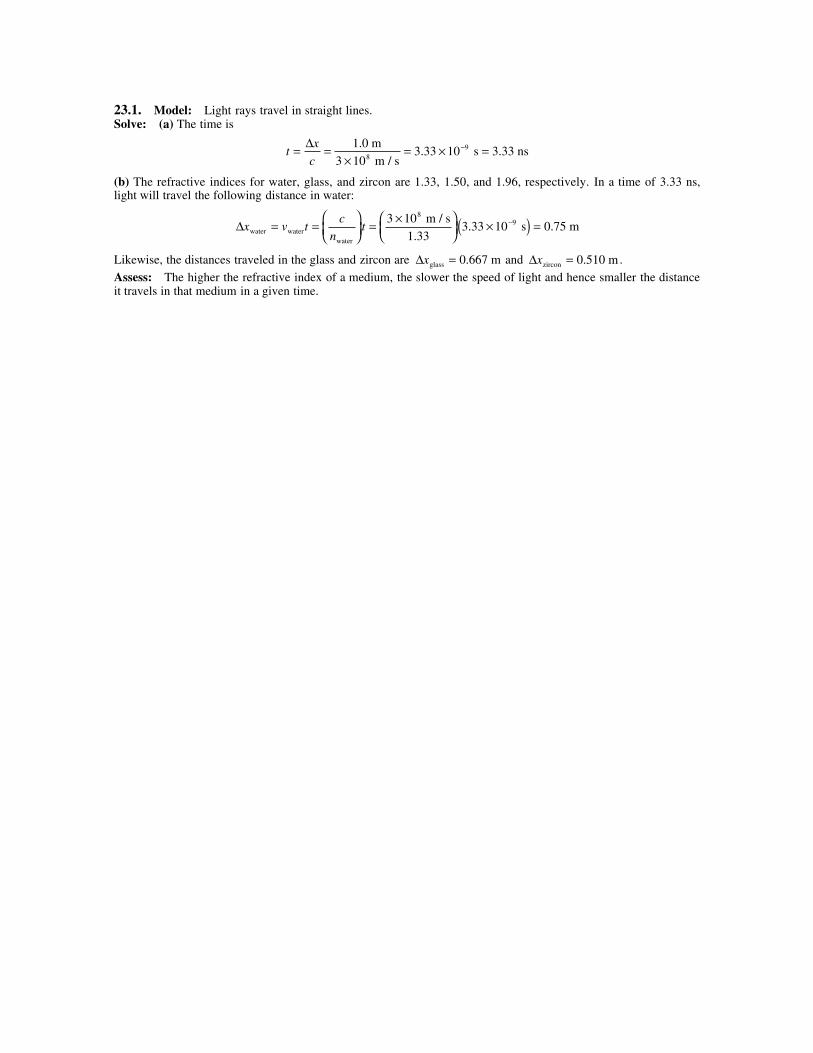
23.1. Model: Light rays travel in straight lines. Solve: (a) The time is t x c = = × = × = − ∆ 1.0 m m/s s 3.33 ns 3 10 3 33 10 8 9 . (b) The refractive indices for water, glass, and zircon are 1.33, 1.50, and 1.96, respectively. In a time of 3.33 ns, light will travel the following distance in water: ∆x v t c n t water water water m/s s 0.75 m = = = × × ( ) = − 3 10 1 33 3 33 10 8 9 . . Likewise, the distances traveled in the glass and zircon are ∆x glass 0.667 m = and ∆x zircon 0.510 m = . Assess: The higher the refractive index of a medium, the slower the speed of light and hence smaller the distance it travels in that medium in a given time.
Transcript
23.1. Model: Light rays travel in straight lines.Solve: (a) The time is
tx
c= =
×= × =−∆ 1.0 m
m / s s 3.33 ns
3 103 33 108
9.
(b) The refractive indices for water, glass, and zircon are 1.33, 1.50, and 1.96, respectively. In a time of 3.33 ns,light will travel the following distance in water:
∆x v tc
ntwater water
water
m / s s 0.75 m= =
= ×
×( ) =−3 10
1 333 33 10
89
..
Likewise, the distances traveled in the glass and zircon are ∆xglass 0.667 m= and ∆xzircon 0.510 m= .
Assess: The higher the refractive index of a medium, the slower the speed of light and hence smaller the distanceit travels in that medium in a given time.
23.2. Model: Light rays travel in straight lines.Solve: Let tglass, toil, and tplastic be the times light takes to pass through the layers of glass, oil, and plastic. The timefor glass is
tx
v
x
c n
x n
cglassglass glass
glass m
m / s0.050 ns= = = =
×( )( )×
=−∆ ∆ ∆ 1 0 10 1 50
3 0 10
2
8
. .
.
Likewise, toil 0.243 ns= and tplastic 0.106 ns= . Thus, ttotal = tglass + toil + tplastic = 0.050 ns + 0.243 ns + 0.106 ns =0.399 ns = 0.40 ns.Assess: The small time is due to the high value for the speed of light.
23.3. Model: Light rays travel in straight lines. The light source is a point source.Visualize:
Solve: Let w be the width of the aperture. Then from the geometry of the figure,
w
2.0 m
12.0 cm
2.0 m 1.0 m=
+ ⇒ w = 8.0 cm
23.4. Model: Light rays travel in straight lines. Also, the red and green light bulbs are point sources.Visualize:
Solve: The width of the aperture is w = 1 m. From the geometry of the figure for red light,
w x2
1 m 3 m 1 m= ′
+⇒ ′ = = ( ) =x w2 2 1.0 m 2.0 m
The red light illuminates the wall from x = 0.50 m to x = 4.50 m. For the green light,
w x4 1
1 m 3 m 1 m=
+⇒ x1 = 1.0 m
3 4 2w x
1 m 3 m 1 m=
+⇒ x2 = 3.0 m
Because the back wall exists only for 2.75 m to the left of the green light source, the green light has a range from x =0 m to x = 3.75 m.
23.5. Model: Light rays travel in straight lines.Visualize:
Solve: From the geometry of the diagram,
tanθ = =5.0 cm
20 cm
167 m
x⇒ x = ( )
=167 m
20.0 cm
5.0 cm668 m
23.6. Model: Use the ray model of light.Visualize:
According to the law of reflection, θ θr i= .Solve: From the geometry of the diagram,
θ φi + = °90 θ φr + ° −( ) = °60 90
Using the law of reflection, we get
90 90 60° − = ° − ° −( )φ φ ⇒ φ = °30
Assess: The above result leads to a general result for plane mirrors: If a plane mirror rotates by an angle φrelative to the horizontal, the reflected ray makes an angle of 2φ with the horizontal.
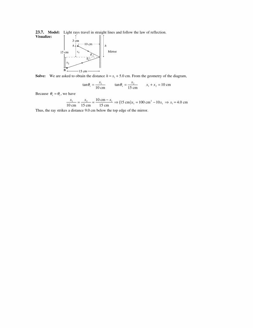
23.7. Model: Light rays travel in straight lines and follow the law of reflection.Visualize:
Solve: We are asked to obtain the distance h = x1 + 5.0 cm. From the geometry of the diagram,
tanθ i 10 cm= x1 tanθ r 15 cm
= x2 x x1 2+ = 10 cm
Because θ θr i= , we have
x x x1 2 1
10 cm 15 cm
10 cm
15 cm= = − ⇒ 15 cm 100 cm2( ) = −x x1 110 ⇒ x1 = 4.0 cm
Thus, the ray strikes a distance 9.0 cm below the top edge of the mirror.
23.8. Model: Light rays travel in straight lines and follow the law of reflection.Visualize:
Solve: (a) The top edge of the mirror reflects a ray of light toward the right wall’s top edge. Similarly, the bottomedge of the mirror reflects the light toward the right wall’s bottom edge. The top edge of the mirror is a distance x1
below the ceiling. The distance of the upper edge of the mirror to a perpendicular line from the light to the mirror isx2. From the geometry of the diagram,
x x1 2
4 m 1 m= x x1 2 1 5+ = =3 m
2 m.
⇒ = − ⇒ = −( ) ⇒ =x x x x x2 1 1 1 141.5 m 1.5 m 1.2 m ⇒ xx
21
4= = =1.2 m
40.30 m
Thus the top edge of the mirror is 1.20 m from the ceiling and the height of the mirror is 0.60 m.(b) Let the shadow’s length be s. Using the geometry of the rays,
sS
2.9 m 0.1 m
10 cm
10 cm m
+= ⇒ = 3 0.
This means the shadow is the height of the right wall, 3.0 m.
23.9. Model: Light rays travel in straight lines and follow the law of reflection.Visualize:
To determine the angle φ , we must know the point P on the mirror where the ray is incident. P is a distance x2 fromthe far wall and a horizontal distance x1 from the laser source. The ray from the source must strike P so that theangle of incidence θi is equal to the angle of reflection θr.Solve: From the geometry of the diagram,
tanφ = =1.5 m 3 m
x x2 1
x1 + x2 = 5 m
⇒−
= ⇒ ( ) = − ( )1.5 m
5 m
3 m1.5 m 15 m 3 m2
x xx x
1 11 1 ⇒ =x1
10
3 m
⇒ = = = ⇒ = °tan .φ φ3 m
x1
9
100 90 42
23.10. Model: Use the ray model of light.Visualize:
The arrow is at a distance s from the mirror, so its image is at a distance s′ behind the mirror. When you are at x = 0 m, aray from the arrow’s head, after reflection from the mirror, is able to enter your eye. Similarly, a ray from the arrow’stail, after normal incidence, is reflected into the eye. That is, the eye is able to see the arrow’s head and tail. Whilewalking toward the right, a ray from the arrow’s head will reflect from the mirror’s right edge and enter your eye at P. Aray starting from the arrow’s tail will also enter your eye when you are at P. That is, while at P you will be able tosee the entire image of the arrow. However, the light from the arrow’s head can never reach beyond point P.Solve: Point P is a distance x from the origin. From the geometry of the diagram,
tan .φ = = = −+
= − ⇒ = − ⇒ =1 m 1 m
2 m
2 m
1 m
2 m
3 m
2 m
3 m m
s
x
s
x xx
1
23 5
Thus, the range of x over which you can see the entire arrow in the mirror is 0 m to 3.5 m.
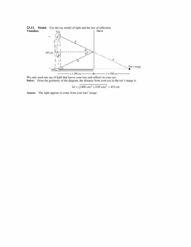
23.11. Model: Use the ray model of light and the law of reflection.Visualize:
We only need one ray of light that leaves your toes and reflects in your eye.Solve: From the geometry of the diagram, the distance from your eye to the toe’s image is
2 400 165 4332 2d = + =( ) ( ) cm cm cm
Assess: The light appears to come from your toes’ image.
23.12. Model: Use the ray model of light and Snell’s law.Visualize:
Solve: According to Snell’s law for the air-water and water-glass boundaries,
n nair air water watersin sinθ θ= n nwater water glass glasssin sinθ θ=
From these two equations, we have
n nair air glass glasssin sinθ θ= ⇒ sin sin.
.sinθ θglass
air
glassair= =
°n
n
1 0
1 5060 ⇒ θglass
= °
= °−sin
sin
..1 60
1 535 3
23.13. Model: Use the ray model of light.Visualize:
The figure incorporates the steps of Tactics Box 23.1.Solve: Using Snell’s law at the water-diamond boundary,
n nn
ndia dia water water waterdia
waterdia watersin sin sin sin
.
.sin . .θ θ θ θ θ= ⇒ = =
° = ⇒ = °2 41
1 3330 0 9060 65 0
Assess: The smaller the refractive index, the larger is the angle of incidence.
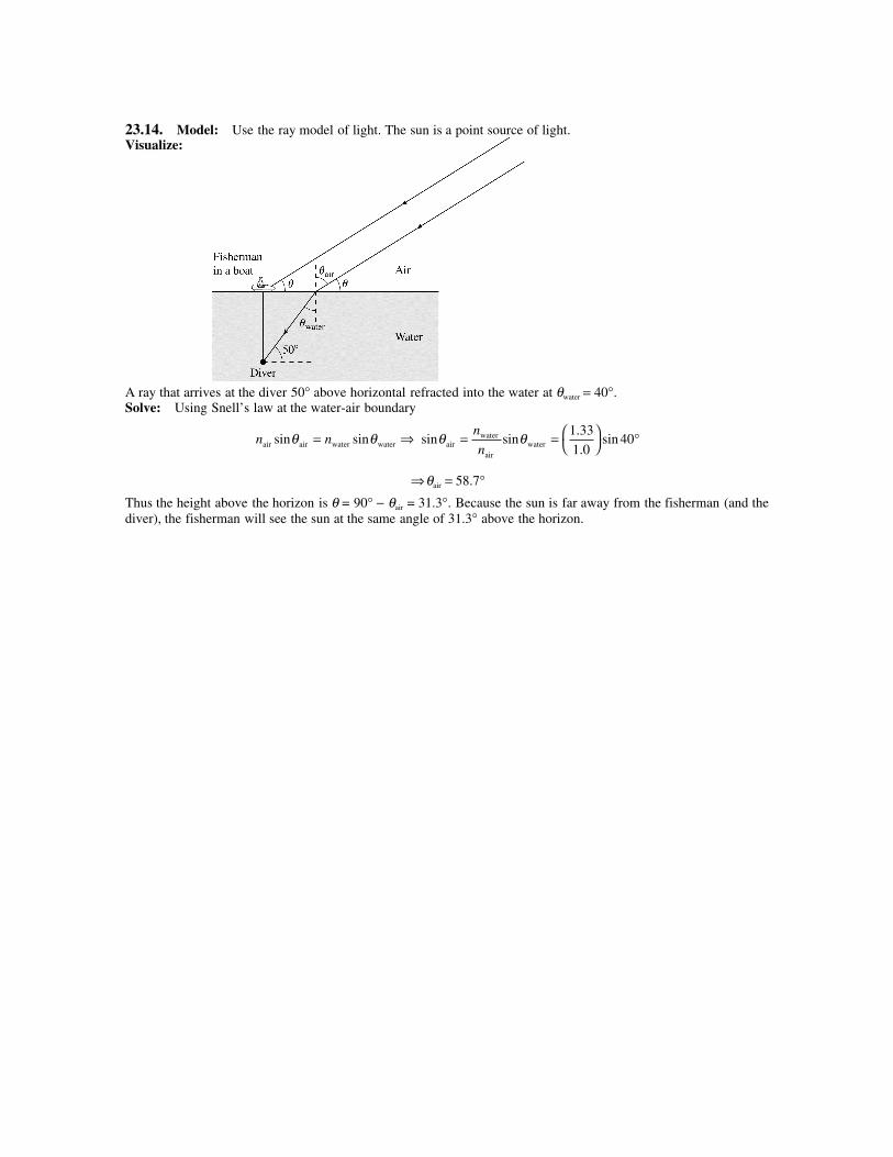
23.14. Model: Use the ray model of light. The sun is a point source of light.Visualize:
A ray that arrives at the diver 50° above horizontal refracted into the water at θwater = 40°.Solve: Using Snell’s law at the water-air boundary
n nair air water watersin sinθ θ= ⇒ sin sin.
.sinθ θair
water
airwater= =
°n
n
1 33
1 040
⇒θair = 58.7°Thus the height above the horizon is θ = 90° − θair = 31.3°. Because the sun is far away from the fisherman (and thediver), the fisherman will see the sun at the same angle of 31.3° above the horizon.
23.15. Model: Represent the laser beam with a single ray and use the ray model of light.Solve: Using Snell’s law at the air-water boundary,
n nair air liquid liquidsin sinθ θ= ⇒ n nliquid airair
liquid
= = °°
=sin
sin.
sin
sin.
θθ
1 037
261 37
Assess: As expected, nliquid is larger than nair.
23.16. Model: Use the ray model of light. For an angle of incidence greater than the critical angle, the ray oflight undergoes total internal reflection.Visualize:
Solve: The critical angle of incidence is given by Equation 23.9:
θccladding
core
=
=
= °− −sin sin
.
..1 1 1 48
1 6067 7
n
n
Thus, the maximum angle a light ray can make with the wall of the core to remain inside the fiber is 90° − 67.7° =22.3°.Assess: We can have total internal reflection because ncore > ncladding.
23.17. Model: Use the ray model of light. For an angle of incidence greater than the critical angle, the ray oflight undergoes total internal reflection.Visualize:
Solve: The critical angle of incidence is given by Equation 23.9:
θcoil
glass
=
=
= °− −sin sin
.
..1 1 1 46
1 5076 7
n
n
Assess: The critical angle exists because noil < nglass.
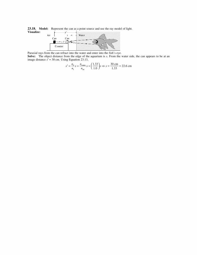
23.18. Model: Represent the can as a point source and use the ray model of light.Visualize:
Paraxial rays from the can refract into the water and enter into the fish’s eye.Solve: The object distance from the edge of the aquarium is s. From the water side, the can appears to be at animage distance s′ = 30 cm. Using Equation 23.13,
′ = = =
s
n
ns
n
ns s2
1
1 33
1 0water
air
.
.⇒ s = =30 cm
1.3322.6 cm
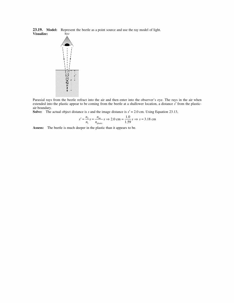
23.19. Model: Represent the beetle as a point source and use the ray model of light.Visualize:
Paraxial rays from the beetle refract into the air and then enter into the observer’s eye. The rays in the air whenextended into the plastic appear to be coming from the beetle at a shallower location, a distance s′ from the plastic-air boundary.Solve: The actual object distance is s and the image distance is s′ = 2.0 cm. Using Equation 23.13,
′ = =sn
ns
n
ns2
1
air
plastic
⇒ 2.0 cm1.0
1.59= s ⇒ s = 3.18 cm
Assess: The beetle is much deeper in the plastic than it appears to be.
23.20. Model: Represent the diver’s head and toes as point sources. Use the ray model of light.Visualize:
Paraxial rays from the head and the toes of the diver refract into the air and then enter into your eyes. When theserefracted rays are extended into the water, the head and the toes appear elevated toward you.Solve: Using Equation 23.13,
′ = =sn
ns
n
nsT T
air
waterT
2
1
′ =sn
nsH
air
waterH
Subtracting the two equations, her apparent height is
′ − ′ = −( ) = ( ) =s sn
ns sH T
air
waterH T 150 cm 113 cm
1 0
1 33
.
.
23.21. Model: Represent the aquarium’s wall as a point source, and use the ray model of light.Visualize:
Paraxial rays from the outer edge (O) are refracted into the water and then enter into the fish’s eye. When extendedinto the wall, these rays will appear to be coming from O′ rather from O. The point on the inside edge (I) of thewall will not change its apparent location.Solve: We are given that sO − sI = 4.00 mm and ′ − ′ =s sO I 3.50 mm . Using Equation 23.13,
′ =sn
nsO
water
wallO ′ =s
n
nsI
water
wallI
⇒ ′ − ′ = −( )s sn
ns sO I
water
wallO I ⇒ 3.50 mm 4.00 mm
wall
= ( )1 33.
n⇒ nwall
4.00 mm
3.50 mm= ( )
=1 33 1 52. .
23.22. Model: Use the ray model of light.Visualize:
23.23. Model: Use the ray model of light and the phenomenon of dispersion.Visualize:
Solve: (a) From the graph in Figure 23.29, we estimate the index of refraction for the red light (656 nm) to be nred =1.572 and for the blue light (456 nm) to be nblue = 1.587.(b) The angle of incidence onto the rear of the prism is 35°. Using these values for the refractive index and Snell’slaw,
n nred air redsin sin35° = θ ⇒ θ red = °
= °−sin
. sin
..1 1 572 35
1 064 4
n nblue air bluesin sin35° = θ ⇒ θblue = °
= °−sin
. sin
..1 1 587 35
1 065 5
⇒ ∆θ θ θ= − = °blue red 1 1.
23.24. Model: Use the ray model of light and the phenomenon of dispersion.Visualize:
Solve: Using Snell’s law for the red light,
n nair air red redsin sinθ θ= ⇒ 1 0 1 45 26 3. sin . sin .θair = ° ⇒ θair = °( ) = °−sin . sin . .1 1 45 26 3 40 0
Now using Snell’s law for the violet light,
n nair air violet violetsin sinθ θ= ⇒ 1 0 40 0 25 7. sin . sin .° = °nviolet ⇒ nviolet = 1.48
Assess: As expected, nviolet is slightly larger than nred.
23.25. Model: The intensity of scattered light is inversely proportional to the fourth power of the wavelength.Solve: We want to find the wavelength of infrared light such that I IIR = 0 01 500. . Because I500
4∝ ( )−500 nm and
IIR ∝ −λ 4 , we have
I
I500
4
100IR 500 nm
=
=λ ⇒ λ = 1580 nm
23.26. Model: Use ray tracing to locate the image.Solve:
The figure shows the ray-tracing diagram using the steps of Tactics Box 23.2. You can see from the diagram thatthe image is in the plane where the three special rays converge. The image is inverted and is located at s′ = 20.0 cmto the right of the converging lens.
23.27. Model: Use ray tracing to locate the image.Solve:
The figure shows the ray-tracing diagram using the steps of Tactics Box 23.2. You can see from the diagram thatthe image is in the plane where the three special rays converge. The image is located at s′ = 15 cm to the right of theconverging lens, and is inverted.
23.28. Model: Use ray tracing to locate the image.Solve:
The figure shows the ray-tracing diagram using the steps of Tactics Box 23.2. You can see that the rays afterrefraction do not converge at a point on the refraction side of the lens. On the other hand, the three special rays,when extrapolated backward toward the incidence side of the lens, meet at P′ which is 15 cm from the lens. That is,s′ = −15 cm. The image is upright.
23.29. Model: Use ray-tracing to locate the image.Solve:
The figure shows the ray tracing diagram using the steps of Tactics Box 23.3. The three rays after refraction do notconverge at a point, but they appear to come from P′. P′ is 6 cm from the diverging lens, so s′ = −6 cm. The imageis upright.
23.30. Model: Assume the biconvex lens is a thin lens.Visualize: Please refer to Figure Ex23.30.Solve: If the object is on the left, then the first surface has R1 = +40 cm (convex toward the object) and the secondsurface has R2 = −40 cm (concave toward the object). The index of refraction of glass is n = 1.50, so the lensmaker’s equation is
11
1 11 50 1
1 1
1 2fn
R R= −( ) −
= −( ) −−
.
40 cm 40 cm⇒ f = 40 cm
23.31. Model: Assume the planoconvex lens is a thin lens.Visualize: Please refer to Figure Ex23.31.Solve: If the object is on the left, then the first surface has R1 = ∞ and the second surface has R2 = −40 cm(concave toward the object). The index of refraction of polystyrene plastic is 1.59, so the lens-maker’s equation is
11
1 11 59 1
1 1
1 2fn
R R= −( ) −
= −( )∞
−−
.
40 cm⇒ 1 0 59
f= .
40 cm⇒ f = 68 cm
23.32. Model: Assume the biconcave lens is a thin lens.Visualize: Please refer to Figure Ex23.32.Solve: If the object is on the left, then the first surface has R1 = −40 cm (concave toward the object) and thesecond surface has R2 = +40 cm (convex toward the object). The index of refraction of glass is 1.50, so the lens-maker’s equation is
11
1 11 50 1
1 10 50
1
1 2fn
R R= −( ) −
= −( )−
−+
= ( ) −
. .
40 cm 40 cm 20 cm⇒ f = −40 cm
23.33. Model: Assume the meniscus lens is a thin lens.Visualize: Please refer to Figure Ex23.33.Solve: If the object is on the left, then the first surface has R1 = −30 cm (concave toward the object) and thesecond surface has R2 = −40 cm (concave toward the object). The index of refraction of polystyrene plastic is 1.59,so the lens-maker’s equation is
11
1 11 59 1
1 1
1 2fn
R R= −( ) −
= −( )−
−−
.
30 cm 40 cm⇒ f = −203 cm
23.34. Model: The water is a spherical refracting surface. Consider the paraxial rays that refract from the airinto the water.Solve: If the cat’s face is 20 cm from the edge of the bowl, then s = +20 cm. The spherical fish bowl surface hasR = +25 cm, because it is the convex surface that is toward the object. Also n1 = 1 (air) and n2 = 1.33 (water). UsingEquation 23.21,
n
s
n
s
n n
R1 2 2 1+
′= − ⇒ +
′= − = = −1 1 33 1 33 1 0 33 1
20 cm 25 cm 25 cm0.0132 cm
. . .
s
⇒ 1 33
0 0132 0 050 1.. .
′= −( ) −
s cm ⇒ s′ = −36.1 cm
This is a virtual image located 36.1 cm outside the fishbowl. The fish, inside the bowl, sees the virtual image. Thatis, the fish sees the cat’s face 36.1 cm from the bowl.
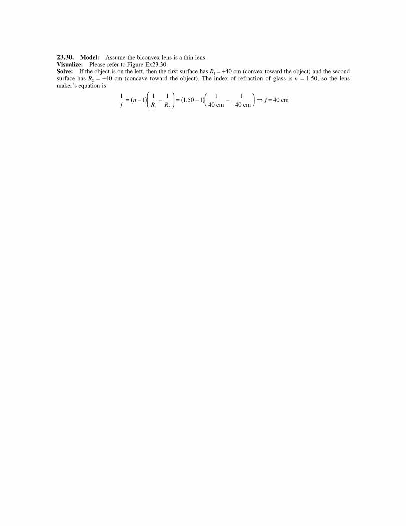
23.35. Model: Model the bubble as a point source and consider the paraxial rays that refract from the plasticinto the air. The edge of the plastic is a spherical refracting surface.Visualize:
Solve: The bubble is at P, a distance of 2.0 cm from the surface. So, s = 2.0 cm. A ray from P after refractingfrom the plastic-air boundary bends away from the normal axis and enters the eye. This ray appears to come fromP′, so the image of P is at P′ and it is a virtual image. Because P faces the concave side of the refracting surface, R =−4.0 cm. Furthermore, n1 = 1.59 and n2 = 1.0. Using Equation 23.21,
n
s
n
s
n n
R1 2 2 1+
′= − ⇒
1 59 1 0 1 0 1 59 0 59 1. . . . .
2.0 cm 4.0 cm 4.0 cm0.1475 cm+
′= −
−= + = −
s
⇒ 1 1 1
′= −− −
s0.1475 cm 0.795 cm ⇒s′ = −1.54 cm
That is, the bubble appears 1.54 cm beneath the surface.
23.36. Model: Diffraction prevents focusing light to an arbitrarily small point. Model the lens of diameter D asan aperture in front of an ideal lens with an 8.0 cm focal length.Solve: Assuming that the incoming laser beam is parallel, the focal length of the lens should be 8.0 cm. FromEquation 23.28, the minimum spot size in the focal plane of this lens is
wf
D= 2 44. λ ⇒ 10 10
633 10 8 0 106
9 2
× =×( ) ×( )−
− −
m 2.44 m m.
D⇒D = 0.0124 m = 1.24 cm
23.37. Model: Two objects are marginally resolvable if the angular separation between the objects, as seenfrom the lens, is α λ= 1 22. D.Solve: Let ∆y be the separation between the two light bulbs, and let L be their distance from a telescope. Thus,
α λ= =∆y
L D
1 22. ⇒ Ly D= =
( ) ×( )×( ) =
−
−
∆1 22
4 0 10
1 22 600 10
2
9.
.
.λ1.0 m m
m54.6 km
23.38. Model: The speed of light in a material is determined by the refractive index as v c n= .Solve: To acquire data from memory, a total time of only 2.0 ns is allowed. This time includes 0.5 ns that thememory unit takes to process a request. Thus, the travel time for an infrared light pulse from the central processingunit to the memory unit and back is 1.5 ns. Let d be the distance between the central processing unit and thememory unit. The refractive index of silicon for infrared light is nSi = 3.5. Then,
1.5 ns 1.5 ns s m / s
Si Si
Si
Si
= = = ⇒ = ( ) =×( ) ×( )
( )
−2 2 2
2
1 5 10 3 0 10
2 3 5
9 8d
v
d
c n
dn
cd
c
n
. .
.⇒d = 6.43 cm
23.39. Model: Treat the red ball as a point source and use the ray model of light.Solve: (a) Using the law of reflection, we can obtain 3 images of the red ball.(b) The images of the ball are located at B, C and D. Relative to the intersection point of the two mirrors, thecoordinates of B, C, and D are: B(+1 m, −2 m), C(−1 m, +2 m) and D(+1 m, +2 m).(c)
23.40. Model: Treat the laser beam as a ray and use the ray model of light.Visualize:
Solve: From the geometry of the mirrors and the rays, β α φ= ° ° = °50 20, = 30 and , .
23.41. Model: For a mirror, the image distance behind the mirror equals the object’s distance in front of the mirror.Visualize:
Solve: Your face is 2.0 from the mirror into which you are looking. The image of your face (image 1) is 2.0 mbehind the mirror, or 4.0 m away. Behind you, the image of the back of your head (image 2) is 3.0 m behind themirror on the other wall. You can’t see this image because you’re looking to the right. However, the reflected raysthat appear to come from image 2 (a virtual image) act just like the rays from an object—that is, just as the rayswould if the back of your head were really at the position of image 2. These rays reflect from the mirror 2.0 m infront of you into which you’re staring and form an image (image 3) 8.0 m behind the mirror. This is the image ofthe back of your head that you see in the mirror in front of you. Since you’re 2.0 m from the mirror, the image ofthe back of your head is 10.0 m away.
23.42. Model: Treat the laser beam as a ray and use the ray model of light.Visualize:
As the cylinder rotates by an angle θ, the path of the reflected laser beam changes by an angle 2θ relative to thedirection of incidence.Solve: Because the angle 2θ is very small,
tan.
2 22 0 10 3
θ θ≅ = × − m
5.0 m⇒ θ
π= = ( ) = °1
5000 5000 rad
180 degrees 0.0115
23.43. Model: Use the ray model of light. For an angle of incidence greater than the critical angle, the ray oflight undergoes total internal reflection.Visualize:
For angles θwater that are less than the critical angle, light will be refracted into the air.Solve: Snell’s law at the water-air boundary is n nair air water watersin sinθ θ= . Because the maximum angle of θair is90°, we have
1 0 90 1 33. sin . sin( ) ° = θwater ⇒ θwater =
= °−sin
..1 1
1 3348 75
Applying Snell’s law again to the glass-water boundary,
n nglass glass water watersin sinθ θ= ⇒ θ θglasswater
glasswater=
=
°( )
= °− −sin sin sin. sin .
..1 1 1 33 48 75
1 5041 8
n
n
Thus 41.8° is the maximum angle of incidence onto the glass for which the ray emerges into the air.
23.44. Model: Use the ray model of light.Visualize:
Solve: When the plastic is in place, the microscope focuses on the virtual image of the dot. From the figure, wenote that s = 1.0 cm and s′ = 1.0 cm − 0.4 cm = 0.6 cm. The rays are paraxial, and the object and image distancesare measured relative to the plastic-air boundary. Using Equation 23.13,
′ =sn
nsair
plastic
⇒ 0.6 cm 1.0
1.0 cmplastic
= ( )n
⇒ nplastic
1.0 cm
0.6 cm= = 1 67.
23.45. Model: Use the ray model of light and the law of refraction.Solve: Snell’s law at the air-glass boundary is n nair air glass glasssin sinθ θ= . We require θ θglass air= 1
2 , so
n nair glass glass glasssin sin2θ θ( ) = ⇒ n nair glass glass glass glass2sin cos sinθ θ θ( ) =
⇒ θ θglassglass
airair=
=×
= ° ⇒ = °− −cos cos
.
.. .1 1
2
1 50
2 1 041 4 82 8
n
n
23.46. Model: Use the ray model of light and the law of refraction.Visualize:
Solve: (a) The ray of light strikes the meter stick at Pempty which is a distance L from the zero mark of the meterstick. So,
tan60° = L
50 cm ⇒ L = ( ) ° =50 60 cm 86.6 cmtan
(b) The ray of light refracts at Phalf and strikes the meter stick a distance x x1 2+ from the zero of the meter stick.We can find x1 from the triangle PfullPhalfO′:
tan60 1° = x
25 cm⇒ x1 25= ( ) ° cm tan 60 = 43.30 cm
We also have x2 = ( )25 cm halftanφ . Using Snell’s law,
n nair water halfsin sin60° = φ ⇒ φhalf = °
= °−sin
sin
..1 60
1 3340 63
⇒ = ( ) ° =x2 40 6325 cm 21.45 cmtan . ⇒ x x1 2+ = + =43.30 cm 21.45 cm 64.8 cm
(c) The ray of light experiences refraction at Pfull and the angle of refraction is the same as in part (b). We get
tan tan . .φfull 50 cm cm cm= ⇒ = ( ) ° =x
x33 50 40 63 42 9
23.47. Model: Use the ray model of light. Light undergoes total internal reflection if it is incident on aboundary at an angle greater than the critical angle.Visualize:
Solve: (a) To reach your eye, a light ray must refract through the top surface of the water and into the air. Youcan see in the figure that rays coming from the bottom of the tank are incident on the top surface at fairly smallangles, but rays from the marks near the top of the tank are incident at very large angles—greater than the criticalangle. These rays undergo total internal reflection in the water and do not exit into the air where they can be seen.Thus you can see the marks from the bottom of the tank upward.(b) The highest point you can see is the one from which the ray reaches the top surface at the critical angle θc. For awater-air boundary, the critical angle is θc = sin–1(1/1.33) = 48.75°. You can see from the figure that the depth ofthis point is such that
L
dd
L= ⇒ = =°
=tantan
.
tan( . ).θ
θcc
cm cm
65 0
48 7557 0
Since the marks are every 10 cm, the high mark you can see is the one at 60 cm.
23.48. Model: Use the ray model of light and the law of refraction. Assume the sun is a point source of light.Visualize:
When the bottom of the pool becomes completely shaded, a ray of light that is incident at the top edge of theswimming pool does not reach the bottom of the pool after refraction.Solve: The depth of the swimming pool is d = 4 0. tan m waterθ . We will find the angle by using Snell’s law. We have
n nwater water airsin sinθ = ° ⇒70 θwater = °
= °−sin
sin
..1 70
1 3344 95 ⇒ =
°=d
4.0 m4.0 m
tan .44 95
23.49. Model: Use the ray model of light and the law of refraction. Assume that the laser beam is a ray of light.Visualize:
The laser beam enters the water 2.0 m from the edge, undergoes refraction, and illuminates the goggles. The ray oflight from the goggles then retraces its path and enters your eyes.Solve: From the geometry of the diagram,
Taking advantage of the geometry in the diagram again,
xx
3 03 0 42 26 2 73
.tan . tan . .
m m mwater= ⇒ = ( ) ° =θ
The distance of the goggles from the edge of the pool is 2.73 m + 2.0 m = 4.73 m.
23.50. Model: Use the ray model of light and the law of refraction. Assume that the laser beam is a ray of light.Visualize:
Solve: (a) From the geometry of the diagram at side A,
tanφ = 10 cm
15 cm ⇒ φ =
−tan 1 10
15 ⇒ φ = °33 69.
This means the angle of incidence at side A is θair = 90° − 33.69° = 56.31°. Using Snell’s law at side A,
n nair air water water Asin sinθ θ= ⇒ θwater A = °
= °−sin
. sin .
..1 1 0 56 31
1 33038 73
This ray of light now strikes side B. The angle of incidence at this water-air boundary is θ θwater B water A= ° − =9051 27. ° . The critical angle for the water-air boundary is
θcair
water
=
=
= °− −sin sin
.
..1 1 1 0
1 3348 8
n
n
Because the angle θwater B is larger than θc, the ray will experience total internal reflection.(b) We will now repeat the above calculation with x = 25 cm. From the geometry of the diagram at side A,φ = °21 80. and θair = °68 20. . Using Snell’s law at the air-water boundary,θwater A = °44 28. and θwater B = °45 72. .Because θ θwater B c< , the ray will be refracted into the air. The angle of refraction is calculated as follows:
n nair air B water water Bsin sinθ θ= ⇒ θair B = °
= °−sin
. sin ..1 1 33 45 72
172 2
(c) Using the critical angle for the water-air boundary found in part (a), θwater A = 90° − 48.75° = 41.25°. Accordingto Snell’s law,
n nair air water water Asin sinθ θ= ⇒ θair = °
= °−sin
. sin .
..1 1 33 41 25
1 061 27
⇒ φ = ° − ° = °90 61 27 28 73. .
The minimum value of x for which the laser beam passes through side B and emerges into the air is calculated as follows:
tanφ = 10 cm
x⇒ x =
°=10 cm
18.2 cmtan .28 73
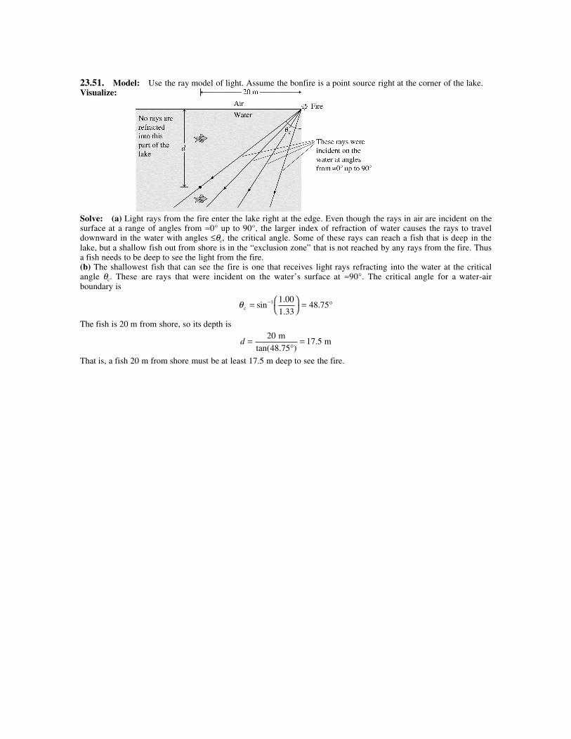
23.51. Model: Use the ray model of light. Assume the bonfire is a point source right at the corner of the lake.Visualize:
Solve: (a) Light rays from the fire enter the lake right at the edge. Even though the rays in air are incident on thesurface at a range of angles from ≈0° up to 90°, the larger index of refraction of water causes the rays to traveldownward in the water with angles ≤θc, the critical angle. Some of these rays can reach a fish that is deep in thelake, but a shallow fish out from shore is in the “exclusion zone” that is not reached by any rays from the fire. Thusa fish needs to be deep to see the light from the fire.(b) The shallowest fish that can see the fire is one that receives light rays refracting into the water at the criticalangle θc. These are rays that were incident on the water’s surface at ≈90°. The critical angle for a water-airboundary is
θc =
= °−sin
.
..1 1 00
1 3348 75
The fish is 20 m from shore, so its depth is
d =°
=20
48 7517 5
m m
tan( . ).
That is, a fish 20 m from shore must be at least 17.5 m deep to see the fire.
23.52. Model: Use the ray model of light. Assume that the target is a point source of light.Visualize:
Solve: From the geometry of the figure with θair = 60°,
Let us find the horizontal distance x2 by applying Snell’s law to the air-water boundary. We have
n nwater water air airsin sinθ θ= ⇒ θwater = °
= °−sin
sin
..1 60
1 3340 63
Using the geometry of the diagram, x2
1.0 m water= tanθ ⇒ x2 40 63= ( ) ° =1.0 m 0.858 mtan .
To determine θtarget, we note that
tan .θ target
3.0 m 3.0 m
3.464 m 0.858 m=
+=
+=
x x1 2
0 6941 ⇒ θtarget = 34.8°
23.53. Model: Use the ray model of light and the phenomena of refraction and dispersion.Visualize:
The refractive index of violet light is greater than the refractive index of red light. The violet wavelength thus getsrefracted more than the red wavelength.Solve: Using Snell’s law for the red light at the air-glass boundary,
n nair air red redsin sinθ θ= ⇒ θ θred
air air
red
=
−sinsin1 n
n= °
= °−sin
. sin
..1 1 0 30
1 51319 30
From the geometry of the diagram,d dred
redviolet
violet10.0 cm 10.0 cm= =tan tanθ θ
⇒ dred 10.0 cm 3.502 cm= ( ) °( ) =tan .19 30 ⇒ dviolet 3.502 cm 0.1 cm 3.402 cm= − =
⇒ =
=
= °− −θviolet
violet
10.0 cm
3.402 cm
10.0 cmtan tan .1 1 18 79
d
That is, white light is incident on a piece of glass at 30°, and it gets dispersed. The violet light makes an angle of18.79° with the vertical. Using Snell’s law,
n nviolet violet air airsin sinθ θ= ⇒ = ( ) °°
=nviolet
1 0 30
18 791 552
. sin
sin ..
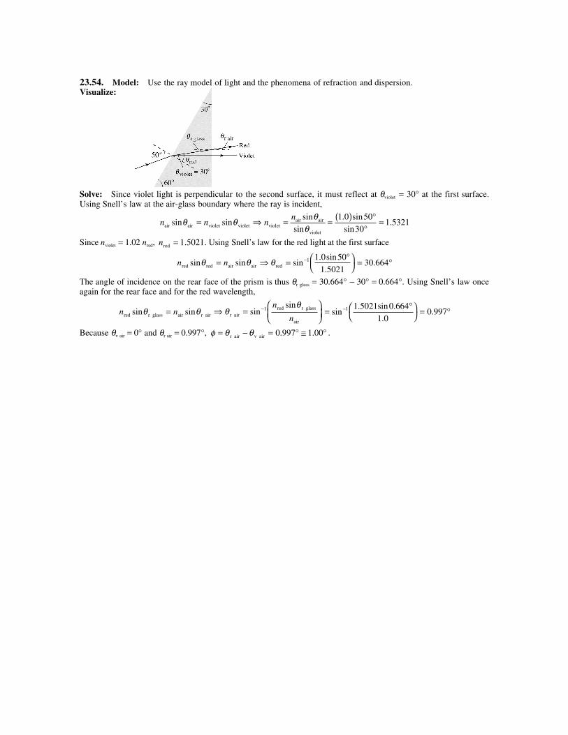
23.54. Model: Use the ray model of light and the phenomena of refraction and dispersion.Visualize:
Solve: Since violet light is perpendicular to the second surface, it must reflect at θviolet = 30° at the first surface.Using Snell’s law at the air-glass boundary where the ray is incident,
n nair air violet violetsin sinθ θ= ⇒ nn
violetair air
violet
= = ( ) °°
=sin
sin
. sin
sin.
θθ
1 0 50
301 5321
Since nviolet = 1.02 nred, nred = 1 5021. . Using Snell’s law for the red light at the first surface
n nred red air airsin sinθ θ= ⇒ θ red = °
= °−sin
. sin
..1 1 0 50
1 502130 664
The angle of incidence on the rear face of the prism is thus θr glass = 30.664° − 30° = 0.664°. Using Snell’s law onceagain for the rear face and for the red wavelength,
n nred r glass air r airsin sinθ θ= ⇒ θθ
r airred r glass
air
=
−sinsin1 n
n= °
= °−sin
. sin .
..1 1 5021 0 664
1 00 997
Because θv air = 0° and θr air = 0.997°, φ θ θ= − = ° ≅ °r air v air 0 997 1 00. . .
23.55. Model: Use the ray model of light and the phenomenon of refraction.Visualize:
Solve: (a) The critical angle θc for the glass-air boundary is
Having determined θglass 1, we can now find θair 1 by using Snell’s law:
n nair air 1 glass glass 1sin sinθ θ= ⇒ θair 1 = × °
= °−sin
. sin .
..1 1 50 11 81
1 017 88
Thus, the smallest angle θ1 for which a laser beam will undergo TIR on the hypotenuse of this glass prism is 17.9°.(b) After reflecting from the hypotenuse (face 3) the ray of light strikes the base (face 2) and refracts into the air.From the triangle BDE,
Snell’s law at the glass-air boundary of face 2 is
n nglass glass 2 air air 2sin sinθ θ= ⇒ θθ
air 2glass glass 2
air
=
−sinsin1 n
n= °
= °−sin
. sin .
..1 1 50 18 19
1 027 9
Thus the ray exits 27.9° left of the normal.
23.56. Model: Use the ray model of light.Visualize: Please refer to Figure P23.56.Solve: (a) Using Snell’s law at the air-glass boundary, with φ being the angle of refraction inside the prism,
n nair sin sinβ φ= ⇒ sin sinβ φ= n
Considering the triangle made by the apex angle and the refracted ray,
90 90 180 12° −( ) + ° −( ) + = ° ⇒ =φ φ α φ α
Thus
sin sin sin sin( )β α β α= ( ) ⇒ = ( )−n n12
1 12
(b) Using the above expression, we obtain
n = = °°
=sin
sin( )
sin .
sin.
βα1
2
52 2
301 58
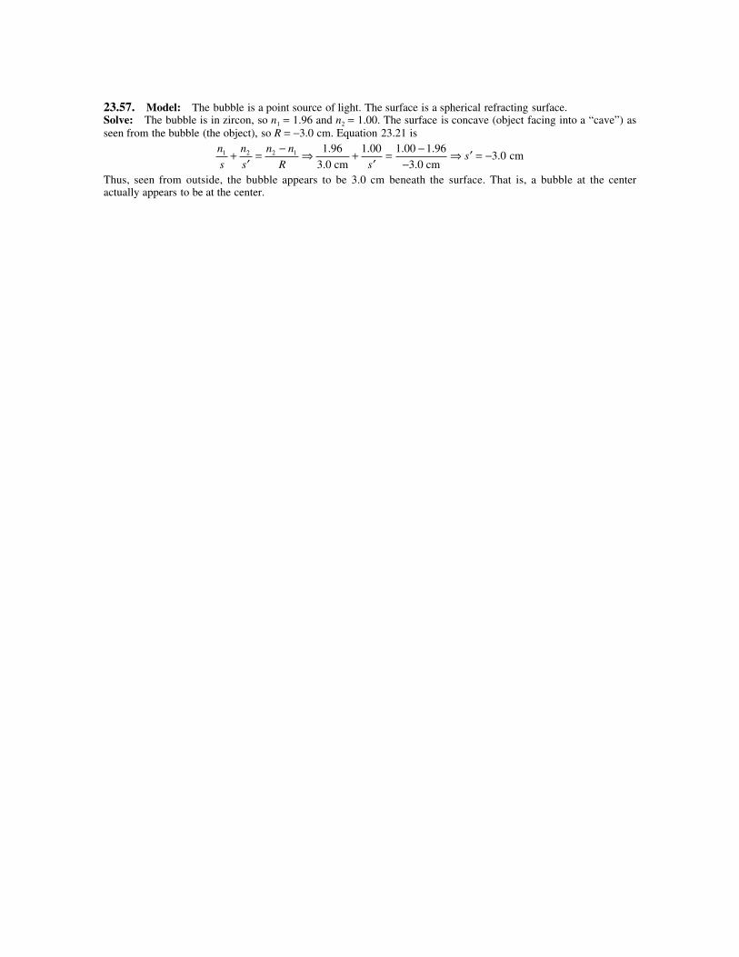
23.57. Model: The bubble is a point source of light. The surface is a spherical refracting surface.Solve: The bubble is in zircon, so n1 = 1.96 and n2 = 1.00. The surface is concave (object facing into a “cave”) asseen from the bubble (the object), so R = −3.0 cm. Equation 23.21 is
n
s
n
s
n n
R1 2 2 1+
′= − ⇒ +
′= −
−⇒ ′ = −1 96 1 00 1 00 1 96
3 0. . . .
.3.0 cm 3.0 cm
cms
s
Thus, seen from outside, the bubble appears to be 3.0 cm beneath the surface. That is, a bubble at the centeractually appears to be at the center.
23.58. Model: Use the ray model of light. The surface is a spherically refracting surface.Visualize:
Solve: Because the rays are parallel, s = ∞. The rays come to focus on the rear surface of the sphere, so s′ = 2R,where R is the radius of curvature of the sphere. Using Equation 23.21,
n
s
n
s
n n
R
n
R
n
Rn1 2 2 1 1
2
12 00+
′= − ⇒
∞+ = − ⇒ = .
23.59. Model: Assume that the converging lens is a thin lens. Use ray tracing to locate the image.Solve: (a)
The figure shows the ray-tracing diagram using the steps of Tactics Box 23.2. The three rays after refractionconverge to give an image at s′ = 40 cm. The height of the image is h′ = 2 cm.(b) Using the thin-lens formula,
1 1 1 1 1 1
s s f s+
′= ⇒ +
′=
40 cm 20 cm⇒ 1 1
′=
s 40 cm⇒ ′ =s 40 cm
The image height is obtained from
Ms
s= − ′ = − = −40 cm
40 cm1
The image is inverted and as tall as the object, that is, h′ = 2.0 cm. The values for h′ and s′ obtained in parts (a) and(b) agree.
23.60. Model: Use ray tracing to locate the image. Assume that the converging lens is a thin lens.Solve: (a)
The figure shows the ray-tracing diagram using the steps of Tactics Box 23.2. The three special rays thatexperience refraction do not converge at a point. Instead they appear to come from a point that is 15 cm on thesame side as the object itself. Thus s′ = −15 cm. The image is upright and has a height of h′ = 1.5 cm.(b) Using the thin-lens formula,
1 1 1 1 1 1
s s f s+
′= ⇒ +
′=
10 cm 30 cm⇒
1 1
′= −
s 15 m⇒ ′ = −s 15 cm
The image height is obtained from
Ms
s= − ′ = − − = +15 cm
10 cm1 5.
The image is upright and 1.5 times the object, that is, 1.5 cm high. These values agree with those obtained in part (a).
23.61. Model: Use ray tracing to locate the image. Assume that the converging lens is a thin lens.Solve: (a)
The figure shows the ray-tracing diagram using the steps of Tactics Box 23.2. The three special rays after refractingdo not converge. Instead the rays appear to come from a point that is 60 cm on the same side of the lens as theobject, so s′ = −60 cm. The image is upright and has a height of 8.0 cm.(b) Using the thin-lens formula,
1 1 1
s s f+
′= ⇒ 1 1 1
15 cm 20 cm+
′=
s⇒ 1 1
′= −
s 60 cm⇒ ′ = −s 60 cm
The image height is obtained from
Ms
s= − ′ = − − = +60 cm
15 cm4
Thus, the image is 4 times larger than the object or ′ = = = ( ) =h Mh h4 4 2.0 cm 8.0 cm . The image is upright.These values agree with those obtained in part (a).
23.62. Model: Use ray tracing to locate the image. Assume the converging lens is a thin lens.Solve: (a)
The figure shows the ray-tracing diagram using the steps of Tactics Box 23.2. After refraction, the three specialrays converge and given an image 50 cm away from the converging lens. Thus, s′ = +50 cm. The image is invertedand its height is 0.65 cm.(b) Using the thin-lens formula,
1 1 1 1 1 1
s s f s+
′= ⇒ +
′=
75 cm 30 cm⇒
′=1 1
s 50 cm⇒ ′ =s 50 cm
The image height is obtained from
Ms
s= − ′ = − = −50 cm
75 cm
2
3
The image height is ′ = = −( )( ) = −h Mh 2 3/ 1 cm 0.67 cm . Because of the negative sign, the image is inverted.These results agree with those obtained in part (a).
23.63. Model: Use ray tracing to locate the image. Assume the diverging lens is a thin lens.Solve: (a)
The figure shows the ray-tracing diagram using the steps of Tactics Box 23.3. After refraction, the three specialrays do not converge. The rays, on the other hand, appear to meet at a point that is 8.5 cm on the same side of thelens as the object. So ′ = −s 8.5 cm . The image is upright and has a height of 1.1 cm.(b) Using the thin-lens formula,
1 1 1
s s f+
′= ⇒ 1 1 1
15 cm 20 cm+
′=
−s⇒
′= − ⇒ ′ = − = −1 7 60
7ss
60 cm cm 8.6 cm
The image height is obtained from
Ms
s= − ′ = −
−( ) = + =60 / 7 cm
15 cm
4
70 57.
Thus, the image is 0.57 times larger than the object, or ′ = = ( )( ) =h Mh 0 57. 2.0 cm 1.14 cm . The image is uprightbecause M is positive. These values agree, within measurement accuracy, with those obtained in part (a).
23.64. Model: Use ray tracing to locate the image. Assume the diverging lens is a thin lens.Solve: (a)
The figure shows the ray-tracing diagram using the steps of Tactics Box 23.3. After refraction from the diverginglens, the three special rays do not converge. However, the rays appear to meet at a point that is 20 cm on the sameside as the object. So ′ = −s 20 cm. The image is upright and has a height of 0.3 cm.(b) Using the thin-lens formula,
1 1 1 1 1 1
′= − =
−− = −
s f s 30 cm 60 cm 20 cm⇒ ′ = −s 20 cm
The image height is obtained from
Ms
s= − ′ = − − = =20 cm
60 cm
1
30 33.
Thus, ′ = = ( )( ) =h Mh 0 33. 1.0 cm 0.33 cm , and the image is upright because M is positive. These values for s′ andh′ agree with those obtained in part (a).
23.65. Model: Assume the lens is a thin lens and the thin-lens formula applies.Solve: Because we want to form an image of the spider on the wall, the image is real and we need a converginglens. That is, both s′ and s are positive. This also implies that the spider’s image is inverted, so M s s= − ′ = − 1
2 .Using the thin-lens formula with ′ =s s1
2 ,
1 1 1 1 1 112s s f s s f
+′
= ⇒ + = ⇒ = ⇒ =3 1
3s ff
s
We also know that the spider is 2.0 m from the wall, so
s + s′ = 2.0 m = s + 12 s ⇒ s = ( ) =1
3 4.0 m 133.3 cm
Thus, f s= =13 44 4. cm and s′ = 2.0 m –1.33 m = 0.67 m = 67 cm. We need a 44.4 cm focal length lens placed
67 cm from the wall.
23.66. Model: Assume the lens to be a thin lens.Solve: Because we want to form an image of the candle on the wall, we need a converging lens. We haves s+ ′ = 200 cm . Using the thin-lens formula,
1 1 1 1 1 1
s s f s s+
′= ⇒ +
−=
200 cm 32 cm⇒ s s2 0− ( ) + =200 cm 6400 cm2
The two solutions to this equation are s = 160 cm and 40 cm. When s = 160 cm, then ′ = − =s 200 cm 160 cm40 cm . The magnification is
Ms
s= − ′ = − = −40 cm
160 cm0 25.
so the image is inverted and its height is (2.0 cm)(0.25) = 0.50 cm. When s = 40 cm, then s′ = 200 cm − 40 cm =160 cm. The magnification is
Ms
s= − ′ = − = −160 cm
40 cm4
so the image is again inverted and its height is (2.0 cm)(4) = 8.0 cm.
23.67. Model: The eye is a converging lens and assume it is a thin lens.Solve: (a) The diameter of an adult eyeball is typically 4.0 cm.(b) The near point distance is approximately 14 inches ≈ 36 cm.(c) Using the thin-lens formula,
1 1 1
s s f+
′= ⇒ 1 1 1
36 cm 4.0 cm+ =
f⇒ 1 10
f=
36 cm⇒ f ≈ 3.6 cm
23.68. Model: Assume the projector lens is a thin lens.Solve: (a) The absolute value of the magnification of the lens is
Mh
h= ′ = =98 cm
2 cm49
Because the projector forms a real image of a real object, the image will be inverted. Thus,
Ms
s= − = − ′
49 ⇒ ′ =s s49
We also have
s + s′ = 300 cm ⇒ s + 49s = 300 cm ⇒ s = 6.0 cm ⇒ s′ = 294 cm
Using these values of s and s′, we can find the focal length of the lens:
1 1 1 1 1
f s sf= +
′= + ⇒ =
6.0 cm 294 cm5.88 cm
(b) From part (a) the lens should be 6.0 cm from the slide.
23.69. Model: Assume the symmetric converging lens is a thin lens.Solve: Because the lens forms a real image on the screen of a real object, the image is inverted. Thus,M s s= − = − ′2 . Also,
s + s′ = 60 cm ⇒ s +2s = 60 cm ⇒ s = 20 cm ⇒ s′ = 40 cm
We can use the thin-lens formula to determine the radius of curvature of the symmetric converging lens R R1 2=( )as follows:
1 1 11
1 1
1 2s s fn
R R+
′= = −( ) −
Using R R1 = + (convex toward the object), R R2 = − (concave toward the object), and n = 1.59,
1 11 59 1
1 1
20 cm 40 cm+ = −( ) −
−
.R R
⇒ 3 1 18
40 cm= .
R⇒ R = 15.7 cm
23.70. Model: Each lens is a thin lens. The image of the first lens is the object for the second lens.Visualize:
The figure shows the two lenses and a ray-tracing diagram. The ray-tracing shows that the lens combination willproduce a real, inverted image behind the second lens.Solve: (a) From the ray-tracing diagram, we find that the image is ≈50 cm from the second lens and the height ofthe final image is 4.5 cm.(b) s1 = 15 cm is the object distance of the first lens. Its image, which is a virtual image, is found from the thin-lensequation:
1 1 1 1 1 5
1 1 1′= − = − = −
s f s 40 cm 15 cm 120 cm⇒ ′ = −s1 24 cm
The magnification of the first lens is
ms
s11
1
1 6= − ′ = −−( ) =
24 cm
15 cm.
The image of the first lens is now the object for the second lens. The object distance is s2 = 24 cm + 10 cm = 34 cm.A second application of the thin-lens equation yields:
1 1 1 1 1
2 2 2′= − = −
s f s 20 cm 34 cm⇒ ′ = =s2
680 cm
1448.6 cm
The magnification of the second lens is
ms
s22
2
1 429= − ′ = − = −48.6 cm
34 cm.
The combined magnification is M m m= = ( ) −( ) = −1 2 1 6 1 429 2 286. . . . The height of the final image is (2.286)(2.0 cm) =4.57 cm. These calculated values are in agreement with those found in part (a).
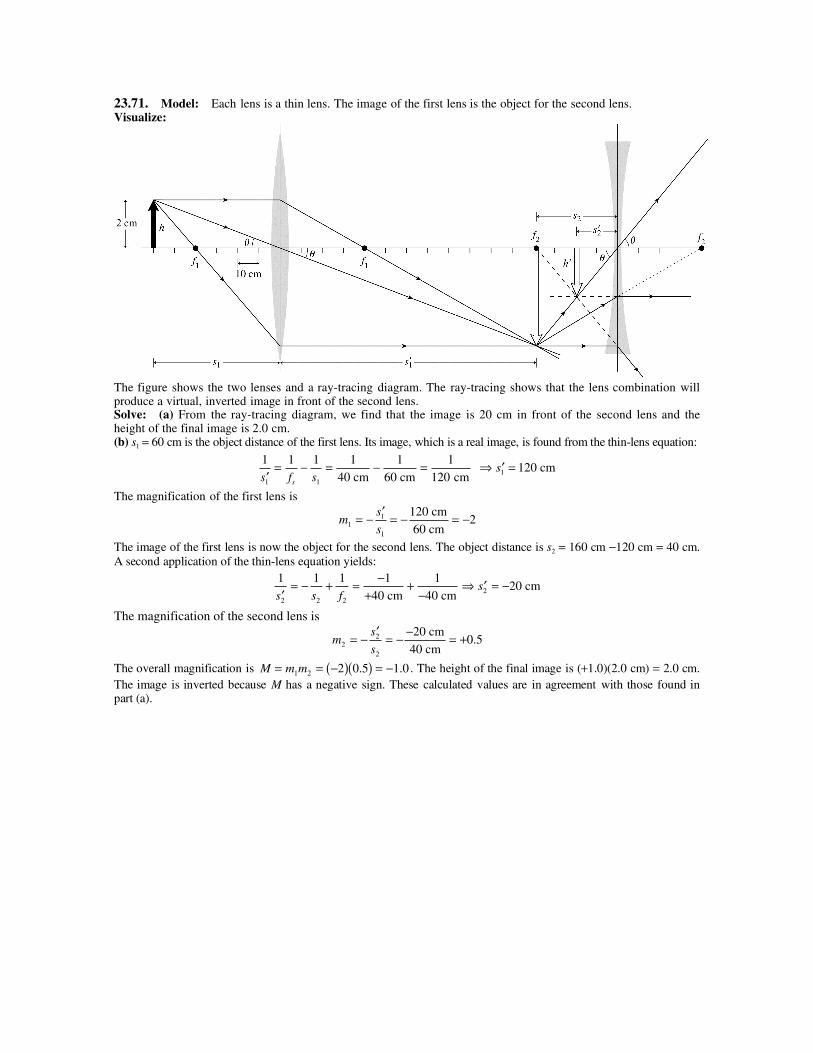
23.71. Model: Each lens is a thin lens. The image of the first lens is the object for the second lens.Visualize:
The figure shows the two lenses and a ray-tracing diagram. The ray-tracing shows that the lens combination willproduce a virtual, inverted image in front of the second lens.Solve: (a) From the ray-tracing diagram, we find that the image is 20 cm in front of the second lens and theheight of the final image is 2.0 cm.(b) s1 = 60 cm is the object distance of the first lens. Its image, which is a real image, is found from the thin-lens equation:
1 1 1 1 1 1
1201 1′= − = − =
s f ss 40 cm 60 cm cm ⇒ ′ =s1 120 cm
The magnification of the first lens is
ms
s11
1
2= − ′ = − = −120 cm
60 cm
The image of the first lens is now the object for the second lens. The object distance is s2 = 160 cm −120 cm = 40 cm.A second application of the thin-lens equation yields:
1 1 1 1 1
2 2 2′= − + = −
++
−s s f 40 cm 40 cm⇒ ′ = −s2 20 cm
The magnification of the second lens is
ms
s22
2
0 5= − ′ = − − = +20 cm
40 cm.
The overall magnification is M m m= = −( )( ) = −1 2 2 0 5 1 0. . . The height of the final image is (+1.0)(2.0 cm) = 2.0 cm.The image is inverted because M has a negative sign. These calculated values are in agreement with those found inpart (a).
23.72. Model: The width of the central maximum that accounts for a significant amount of diffracted lightintensity is inversely proportional to the size of the aperture. The lens is an aperture that focuses light.Solve: To focus a laser beam, which consists of parallel rays from s = ∞ , the focal length needs to match thedistance to the target: f L= = 5 0. cm.The minimum spot size to which a lens can focus is
wf
D D= ⇒ × =
×( ) ×( )−− −
2 445 0 10
5 0 106
6 2.
..λ
m 2.44 1.06 10 m m
⇒D = 2.59 cm.
23.73. Model: Two objects are marginally resolved if the angular separation between the objects, as seen fromyour eye lens, is α λ= 1 22. D.Solve: Let ∆y be the separation between the two headlights of the incoming car and let L be the distance of theselights from your eyes. We will assume the wavelength of the light to be 600 nm. Then,
α λ= = = = ( )×( )−
∆y
L L D
1.20 m 600 nm
m
1 22 1 22
7 0 10 3
. .
.⇒ L =
( ) ×( )( ) ×( ) =
−
−
1.20 m m
m11.5 km
7 0 10
1 22 600 10
3
9
.
.
Assess: The two headlights are not resolvable if L > 11.5 km, marginally resolvable at 11.5 km, and resolvable atL < 11.5 km.
23.74. Model: Two objects are marginally resolved if the angular separation between the objects is α λ= 1 22. D.Visualize:
Solve: (a) The angular separation between the sun and Jupiter is
α
α λ
= × = ×× ×( ) × × ×( )
= ×
= =×( )
⇒ =
−
−
780 10 780 10
4 3 3 0 10 365 24 36001 92 10
1 22 1 22 600 100 038
9 9
8
5
9
m
4.3 light years
m
m rad
m m = 3.8 cm
. ..
. ..
D DD
(b) The sun is vastly brighter than Jupiter, which is much smaller and seen only dimly by reflected light. In theoryit may be possible to resolve Jupiter and the sun, but in practice the extremely bright light from the sun willoverwhelm the very dim light from Jupiter.
23.75. Model: For a diffraction-limited lens, the minimum focal length is the same size as its diameter. Thesmallest spot diameter over which you can focus light is wmin ≈ 2.5λ.Solve: (a) The smallest spot size is wmin . .≈ = ×( ) =−2 5 2 5 800 10 29λ µ m m .(b) The total usable area of the optical disk is
π 11 10 4 102 2 2 2×( ) − ×( )[ ] =− − m m 0.0330 m2
The area of each pit is the area of one bit of information and is 1 25 2 2 52 2
. .( )( )[ ] = [ ]µ µm m . The area of 1 byte is
8 times this quantity and the area of 1 megabyte (MB) of information is 106 times more. This means the number ofmegabytes (MB) of data that can be stored on the disk is
0.0330 m
m MB660 MB
2
8 2 5 10 106 2 6 1× ×( ) ×=
− −.
Assess: A memory storage capacity of 660 MB is reasonable.
23.76. Model: Use the ray model of light.Visualize: Please refer to Figure CP23.76.Solve: (a) The time (t) is the time to travel from A to the interface (t1) and from the interface to B (t2). That is,
t t td
v
d
v
d
c n
d
c n
n d
c
n d
c
n
cx a
n
cw x b= + = + = + = + = + + −( ) +1 2
1
1
2
2
1
1
2
2
1 1 2 2 1 2 2 2 2 2
(b) Because t depends on x and there is only one value of x for which the light travels from A to B in the leastpossible amount of time, we have
dt
dx
n x
c x a
n w x
c w x b= =
+−
−( )−( ) +
0 1
2 2
2
2 2
The solution (hard to do!) would give xmin.(c) From the geometry of the figure,
x
x a
x
d2 21
1+
= = sinθ w x
w x b
w x
d
−
−( ) += − =
2 22
2sinθ
Thus, the condition of part (b) becomesn
c
n
c1
12
2 0sin sinθ θ− = ⇒ n n1 1 2 2sin sinθ θ=
23.77. Model: Use the ray model of light.Visualize:
The angle of refraction is θ δθ2 + for those wavelengths that have a refractive index of n + δn.Solve: (a) Applying Snell’s law to the diagrams,
1 11 2 1 2( ) = ( ) = +( ) +( )sin sin sin sinθ θ θ δ θ δθn n n
Equating the right hand sides of the above two equations and using the formula for the sine of a sum,
n n n n nsin sin cos cos sin sin cosθ δ θ δθ θ δθ δ θ θ δθ2 2 2 2 2= +( ) +( ) = +( ) +( ) where we have assume that δθ θ<< . Multiplying the expressions,
n n n n nsin sin cos sin cosθ θ θ δθ δ θ δ δθ θ2 2 2 2 2= + + +We can ignore the last term on the right hand side because it is the product of two small terms. The equation becomes
n nn
ncos sin tanθ δθ δ θ δθ θ δ
2 2 2= − ⇒ = −
Note that δθ has to be in radians.We can obtain the same result in the following way as well. From Snell’s law,
sinsinθ θ
21=
nDifferentiating relative to n
δ θδ
θ δθδ
θ θ θ
δθ θ δ
sincos sin
sin sin
tan
22 1 2
22
2
2
1
n n n
n
n n
n
n
= = ( ) −
= − = −
⇒ = −
(b) We have θ1 = 30° and nred = 1.552. Because the red wavelength is larger than the violet wavelength, nred < nviolet.Also, if the refraction angle for the red light is θ2, the refraction angle for the violet is less than θ2. Thus, δθ =−0.28°. From the formula obtained in part (a),
δθ θ δ= −
tan 2
n
n⇒ δ
θδθn
n= −tan 2
To determine tanθ2, we note that
n nred airsin sinθ2 30= ° ⇒ θ21 30
1 55218 794= °
= °−sin
sin
.. ⇒ tan .θ2 0 3403=
Thus, the expression for the change in the index of refraction is
δ πn = − − °( )
°
=1 552
0 34030 28 0 0223
.
.. .
rad
180⇒nviolet = nred + δn = 1.552 + 0.022 = 1.574
23.78. Model: Assume the ray model of light. The ball is not a thin lens. However, the image due to refractionfrom the first surface is the object for the second surface.Visualize:
Solve: (a) For refraction from the first surface, R = +5 cm (convex toward the object). Thus,
n
s
n
s
n n
R s ss1
1
2
1
2 1
1 11
1 0 1 50 0 50 1 50 1+′
= − ⇒ +′
= ⇒′
= − ⇒ ′ = −. . . .
6 cm 5 cm 15 cm22.5 cm
The image is virtual (to the left of the surface) and upright.For refraction from the second surface, s2 = 22.5 cm + 10 cm = 32.5 cm and R = −5.0 cm (concave toward the
object). Thus,
1 50 1 0 1 1 50 1
2
. . .
32.5 cm 5.0 cm 10 cm+
′= −
−=
s⇒ 1 1 1 50
22′
= − ⇒ ′ =s
s10 cm 32.5 cm
18.6 cm.
The image is 18.6 cm from the right edge of the ball and thus 23.6 cm from the center.(b) The ray diagram showing the formation of the image is shown above.(c) Using the thin-lens equation,
1 1 1 1
5
1
5
1
s s f f+
′= ⇒
++
+=
6 cm cm 18.6 cm cm⇒ f = 7.5 cm
23.79. Model: Use the ray model of light and assume the lens is a thin lens.Visualize: Please refer to Figure 23.48.Solve: Let n1 be the refractive index of the fluid and n2 the refractive index of the lens. The lens consists of twospherical surfaces having radii of curvature R1 and R2 and the lens thickness t → 0. For the refraction from thesurface with radius R1, we use Equation 23.21:
n
s
n
s
n n
R1
1
2
1
2 1
1
+′
= −
For the refraction from surface with radius R2,n
s
n
s
n n
R2
1
1
2
1 2
2− ′+
′= −
A negative sign is used with ′s1 because the image formed by the first surface of the lens is a virtual image. Thisvirtual image is the object for the second surface. Adding the two equations,
n
s
n
sn n
R R1
1
1
22 1
1 2
1 1+′
= − −
⇒ 1 1 1 1 1
1 2
2 1
1 1 2s s f
n n
n R R+
′= = − −
( )
(b) In air, R1 = +40 cm (convex toward the object), R2 = −40 cm (concave toward the object), n1 = 1.0, and n2 =1.50. So,
1 1 50 1 0
1 0
1 1
f= −
−
−
. .
. 40 cm 40 cm⇒ f = 40 cm
In water, n1 = 1.33 and n2 = 1.50. So,1 1 50 1 33
1 33
1 1
f= −
−
−
. .
. 40 cm 40 cm⇒ f = 156.5 cm
23.80. Model: Use the ray model of light and assume the corrective lens is a thin lens.Visualize:
Because your near point is 100 cm, objects held 25 cm from the eye do not form a focused image in the eye. Acorrective lens produces a virtual image of the object at 100 cm, which is your near point. This virtual image atyour near point serves as the object for your eye.Solve: (a) Using the thin-lens equation,
1 1 1 1 1 3
100f s s= +
′= +
−=
25 cm 100 cm cm ⇒ f = 33.3 cm
(b) The ray diagram is shown above.
23.81. Model: Use the ray model of light and assume the corrective lens is thin.Visualize:
Because your far point is 200 cm, objects an infinite distance from the eye do not form a sharp, focused image. Acorrective lens produces a virtual image of the object at 200 cm, which is your far point. This virtual image at yourfar point serves as the object for your eye.Solve: (a) Using the thin-lens equation,
1 1 1 1 1
f s s= +
′=
∞+
−200 cm⇒ f = −200 cm
(b) The ray diagram is shown above.
23.82. Model: Use the ray model of light. Assume both the lenses are thin lenses.Visualize:
Solve: Begin by finding the image of the diverging lens,
1 1 1
1 1 1s s f+
′= ⇒ 1 1 1
120 cm 20 cm+
′=
−s⇒ ′ = −s1 10 cm
This image is the object for the second lens. Its distance from the screen is s s2 2+ ′ = − =110 cm 10 cm 100 cm. Theoverall magnification is
M m mh
h= = − ′ = −1 2 2
The magnification of the diverging lens is
ms
s11
1
1
2= − ′ = −
−( ) =10 cm
20 cm
Thus the magnification of the converging lens needs to be
ms
s22
2
4= − ′ = − ⇒ ′ =s s2 24
Substituting this result into s s2 2 0+ ′ = 1 0 cm , we have s2 + 4s2 = 100 cm, which means s2 = 20 cm and ′ =s2 80 cm .We can find the focal length by using the thin-lens equation for the converging lens:
1 1 1
2 2 2s s f+
′= ⇒ 1 1 1
2f= +
20 cm 80 cm⇒ f2 = 16 cm
Hence, the second lens is a converging lens of focal length 16 cm. It must be placed 10 cm in front of the diverginglens, toward the screen.


![23.1(1) Accounts. EMPLOYER’SCONTRIBUTIONANDCHARGES - Iowa · IAC2/14/18 WorkforceDevelopment[871] Ch23,p.3 23.1(31)Quarterlywagedetail.Areportlistingworkersandtheirwagesbysocialsecuritynumber.](https://static.documents.pub/doc/80x56/5aec797d7f8b9a585f8ed9fa/2311-accounts-employerscontributionandcharges-iowa-workforcedevelopment871.jpg)


