202
235 MM166 Rev. 10 *MM166*

235
MM166Rev. 10
*MM166*

This manual is furnished with each new TENNANT Model 235. It provides necessary operating and preventivemaintenance instructions. Read this manual completely and understand the machine before operating or servicingit.
This manual covers all machine variations and standard accessories. The tabbed instruction portion of themanual consists of the Specification, Operation, Maintenance, and Appendix sections. The tabbed parts sectionconsists of the Standard Model Parts; LPG Parts; Options; Hydraulic Components; Engine Parts, Gasoline, LPG;and Cross Reference sections.
All right side and left side references to the machine are determined by facing the direction of forward travel. Allhardware considered to be of a common nature or locally available has been omitted from the parts sections. Beaware that this machine may contain metric hardware. Make sure you use equivalent hardware whenreplacement becomes necessary.
This machine will provide excellent service. However, the best results will be obtained at minimum costs if:
D The machine is operated with reasonable care.D The machine is maintained regularly -- per the maintenance instructions provided.D The machine is maintained with Tennant Company supplied or equivalent parts.
Parts and supplies may be ordered by phone or mail from any Tennant Company parts and service center,distributor, or from any of the Tennant Company subsidiaries. Before ordering parts or supplies, be sure to haveyour machine model number and serial number handy. Fill out the data block below for future reference. Thetelephone numbers, telex numbers, mailing addresses, and locations of those outlets are listed in the CustomerDocuments section of the manual.
MACHINE DATA
Please fill out at time of installation.
Machine Serial Number --
Engine Serial Number --
Sales Representative --
Customer Number --
Date of Installation --
Manual Number -- MM166
Revision: 10
Published: 8--95
Trademark Registered in: Austria, Benelux, Denmark, England, France, Germany, Italy, Spain, Switzerland,United States, Argentina, Australia, Canada, Japan, Mexico, Sweden, by TENNANT COMPANY, Minneapolis,Minnesota, U.S.A.
Acknowledgments: Technical information and/or illustrations supplied by Kolher Company, Engine Division.
Copyright 1986, 1987,1988, 1989, 1991, 1993, 1994, 1995 Tennant Company, Printed in U.S.A.

ABOUT THIS MANUAL
a235 MM166 (5--91)
ABOUT THIS MANUAL
The machine manual that you received with yourTENNANT machine contains valuable informationabout the operation and maintenance, andnumerous sections filled with TENNANT partnumbers for the repair of the machine. Pleaseread through this section titled ABOUT THISMANUAL to become familiar with the contents ofthe machine manual, making the information youare looking for easier to find.
The machine manual consists of several sectionsof reference information, and the remaindercontain part number information for orderingrepair parts for the machine. Each section has ashaded bar at the top of the page with the nameof that section. Just as this section has the titleABOUT THIS MANUAL on the top of each page.This way you can tell which section you are in atall times.
REFERENCE SECTIONS
The reference information sections of the manualare; General Information, Specifications,Operation, Maintenance, and Appendix.
GENERAL INFORMATION -- The GeneralInformation section of the manual contains thesafety precautions, the location of the safetylabels on the machine, and a table of contents ofthe entire manual. The Safety Precautions are anoverview of the safety measures to be observedwhen operating and maintaining your machine.The location of the safety labels show themounting location of the safety labels for use inthe replacement of the labels. The table ofcontents in this section is a list of all the table ofcontents that appear in the front of each section inthe manual. This can be used for easy referenceto locate information in a particular section of themanual.
SPECIFICATIONS -- The Specifications section ofthe manual contains machine specificationinformation useful in the operation andmaintenance of the machine. This section givesyou specification information on the engine,electric motors, brake system, hydraulics, fluidcapacities, and machine weight to mention a few.The section also has a illustration of the top andside view of the machine with the height and widthdimensions displayed.
OPERATION -- The Operation section of themanual contains information needed to operatethe machine. This section will list the controls andinstruments on the machine, overview themachine operation, and tell you how to transportand store the machine.
MAINTENANCE -- The Maintenance sectioncontains information on the suggestedmaintenance procedures and adjustments to keepyour machine in top operating condition. Thesection includes a Maintenance Chart listing themaintenance schedule and the areas of themachine to be addressed. Each subject ofmaintenance is covered in more detail in suchareas as Lubrication, Hydraulics, Engine, andElectrical System.
APPENDIX -- The Appendix contains hardwareand hydraulic information. Standard hardwaretorques and identification information is included,plus hydraulic torques if your machine ishydraulically controlled.
PART SECTIONS
The remaining sections of the manual contain partnumber information for ordering repair parts foryour machine. The manual contains part numberinformation on every type of machine modelavailable in the model size of your particularmachine. Therefore there will be part numberinformation in your manual you will not need torefer to when wanting to place an order.
The main thing you need to know about yourmachine is what type of model is it. Is themachine powered by an engine or batteries? If themachine has an engine, is it fueled from gasoline,LPG, or diesel? If it is a mid-sized or largersweeper, is it multi-level or low dump? For thescrubbers, is it SRSr or standard. Determiningthis information about your machine will helpguide you through the separate parts sections tofind the repair part you need.

ABOUT THIS MANUAL
235 MM166 (5--91)b
The smaller line of sweeper and scrubbers haveless complicated part section arrangement, andare easier to find your way through the partssections. The larger machines can have quite avariety of model types which significantlyincreases the size to the machine manual.Because of this, on the larger machine we madethe first part section, Section 5, a part sectionwhich contains parts common to all type of themachine. If the machine has an engine, thissection contains parts information on a gasolinepowered machine.
The remaining sections contain only partsinformation which is unique to that particularmachine type, such as unique diesel parts on themachine, or unique SRSr parts. Knowing themachine model type you have is important whensearching for that part information you need forordering repair parts. Start in that unique sectionfirst when looking for a part, then go to the firstparts section, Section 5, if the part can’t be foundin the unique section.
MACHINE SERIAL NUMBERS
When a design change takes place to a machine,the changes are indicated in the parts sectionswith machine serial numbers. Know the serialnumber of your machine which can be found onthe machine data plate mounted on the machine.Record this number on the inside front cover ofyour manual along with your customer number.
Machine number usage is recorded in theMachine Serial Number column of the parts listsin the parts sections of the manual. If the machineserial number column lists zeros on the left side ofthe dash, then this part is used on all machines;such as (000000-- ).
If the column lists zeros on the left of the dashand a number on the right of the dash, then thepart is used on machines up to and including thatmachine serial number; such as (00000--002345).
For parts that are used on machines beginning atand continuing on from a certain serial number,the column would list a serial number on the left ofthe dash and have blank spaces on the right sideof the dash; such as (002346-- ). This partwould be used on machines starting with thatmachine serial number and greater.
Finally, parts can be used on machines with serialnumbers in a certain block of numbers. In thissituation there is a serial number on the left andright side of the dash. The part is then used on amachine with a serial number starting at thenumber on the left and up to and including thenumber on the right; such as (002346--008900).
PARTS ASSEMBLIES
A part assembly has parts within the assembly,such as a parking brake consisting of othersmaller parts. What parts are contained in a partassembly can be determined by an indentationarrangement in the description column of theparts lists.
Here is an example of a part assembly, in thiscase we will use the parking brake mentionedpreviously:
MachineSerial Number Description Qty.(000000-- ) Parking Brake 1(000000-- ) Pin, Roll 1(000000-- ) Link 1(000000-- ) Spring, Compression 1(000000-- ) Pin, Roll 1(000000-- ) Support 1(000000-- ) Lever, Release 1(000000-- ) Rod, Parking Brake 1(000000-- ) Washer, 0.50” 3
In this example, the parts whose descriptions areindented under the parking brake are all parts ofthe parking brake. When you order the parkingbrake you will receive all the parts listed under it.You also can order any of the individual partslisted under the parking brake if it is the only partyou need.

ABOUT THIS MANUAL
c235 MM166 (5--91)
SUPPLIER COMPONENT BREAKDOWNS
TENNANT purchases certain components of themachine from suppliers. Some of thesecomponents are engines, hydraulic pumps andmotors, electric motors, and solution pumps.
For those purchased components that arerepairable, lists of parts for them appear in thelater part of the parts sections. These are thesupplier breakdowns. The engine breakdowncontains both supplier and TENNANT partsnumbers for repair parts. Breakdowns forhydraulic and electrical components haveTENNANT part numbers for the parts TENNANTsupplies. The serial numbers listed in any of theparts lists in these sections is a serial number themanufacturer uses to identify design changes intheir particular component.
ORDERING REPAIR PARTS
Once you have located a part to order, there areseveral things you need to have to place theorder. At the beginning of each parts section is anOrdering Repair Parts page which lists theinformation you will need to place your order.Review this list before placing the order.

ABOUT THIS MANUAL
235 MM166 (5--91)d

GENERAL INFORMATION
i235 MM166 (5--91)
SAFETY PRECAUTIONS
The following symbols are used throughout thismanual as indicated in their descriptions:
WARNING: To warn of hazards orunsafe practices which could result in
severe personal injury or death.
FOR SAFETY: To identify actions which mustbe followed for safe operation of equipment.
The following information signals potentiallydangerous conditions to the operator orequipment. Read this manual carefully. Knowwhen these conditions can exist. Locate all safetydevices on the machine. Then, take necessarysteps to train machine operating personnel.Report machine damage or faulty operationimmediately. Do not use the machine if it is not inproper operating condition.
FOR SAFETY:
1. Do Not Operate Machine:-- Unless Trained And Authorized.-- Unless Operation Manual Is Read AndUnderstood.
-- In Flammable Or Explosive AreasUnless Designed For Use In ThoseAreas.
-- In Areas With Possible Falling ObjectsUnless Equipped With OverheadGuard.
2. Before Starting Machine:-- Check For Fuel Leaks.-- Keep Sparks And Open Flame AwayFrom Refueling Area.
-- Make Sure All Safety Devices Are InPlace And Operate Properly.
-- Check Brakes And Steering For ProperOperation.
3. When Starting Machine:-- Keep Foot On Brake And DirectionalPedal In Neutral.
4. When Using Machine:-- Use Brakes To Stop Machine.-- Go Slow On Grades And SlipperySurfaces.
-- Use Care When Backing Machine.-- Move Machine With Care WhenHopper Is Raised.
-- Make Sure Adequate Clearance IsAvailable Before Raising Hopper.
-- Do Not Carry Riders On Machine.-- Always Follow Safety And TrafficRules.
5. Before Leaving Or Servicing Machine:-- Stop On Level Surface.-- Set Parking Brake.-- Turn Off Machine And Remove Key.
6. When Servicing Machine:-- Avoid Moving Parts. Do Not WearLoose Jackets, Shirts, Or SleevesWhen Working On Machine.
-- Block Machine Tires Before JackingMachine Up.
-- Jack Machine Up At DesignatedLocations Only. Block Machine UpWith Jack Stands.
-- Use Hoist Or Jack Of AdequateCapacity To Lift Machine.
-- Wear Eye And Ear Protection WhenUsing Pressurized Air Or Water.
-- Disconnect Battery ConnectionsBefore Working On Machine.
-- Avoid Contact With Battery Acid.-- Avoid Contact With Hot EngineCoolant.
-- Allow Engine To Cool.-- Keep Flames And Sparks Away FromFuel System Service Area. Keep AreaWell Ventilated.
-- Use Cardboard To Locate LeakingHydraulic Fluid Under Pressure.
-- Use TENNANT Supplied Or EquivalentReplacement Parts.
WARNING: Engine Emits Toxic Gases.Severe Respiratory Damage Or
Asphyxiation Can Result. Provide AdequateVentilation. Consult With Your RegulatoryAgency For Exposure Limits. Keep EngineProperly Tuned.
WARNING: Machine Can Emit ExcessiveNoise. Consult With Your Regulatory
Agency For Exposure Limits. Hearing LossCan Result. Wear Hearing Protection.
WARNING: Lift Arm Pinch Point. StayClear Of Hopper Lift Arms.
WARNING: Raised Hopper May Fall.Engage Hopper Support Bar.
WARNING: Moving Belt. Keep Away.

GENERAL INFORMATION
235 MM166 (5--91)ii
The following safety labels are mounted on themachine in the locations indicated. If these, orany, labels become damaged or illegible, install anew label in its place.
03403
FOR SAFETY THERMO SENTRYt LABEL --LOCATED ON THE LIFT ARM CROSSMEMBER.
03402
FOR SAFETY LABEL -- LOCATED ON THESIDE OF THE CONTROL PANEL.
03486

GENERAL INFORMATION
iii235 MM166 (5--91)
03398
HOPPER SUPPORT BAR WARNING LABEL --LOCATED ON THE OPERATOR SIDE OFHOPPER LIFT ARM.
03397
FAN BELT DRIVE WARNING LABEL --LOCATED ON THE VACUUM FAN.
03401
HOPPER LIFT ARM PINCH POINT CAUTIONLABEL (2) -- LOCATED ON THE HOPPER LIFTARMS.
03399
FALLING HOPPER WARNING LABEL --LOCATED ON THE FRONT OF THE BRUSHWRAP.
03486

GENERAL INFORMATION
235 MM166 (8--95)iv
CONTENTS
PageGENERAL INFORMATION i. . . . . . . . . . . . . .
SAFETY PRECAUTIONS i. . . . . . . . . . . .
SPECIFICATIONS 1-1. . . . . . . . . . . . . . . . . . . . .MACHINE SPECIFICATIONS 1-3. . . . . . . . .
POWER TYPE 1-3. . . . . . . . . . . . . . . . . . .POWER TRAIN 1-3. . . . . . . . . . . . . . . . . .STEERING 1-3. . . . . . . . . . . . . . . . . . . . . .HYDRAULIC SYSTEM 1-3. . . . . . . . . . . .BRAKING SYSTEM 1-3. . . . . . . . . . . . . .SUSPENSION SYSTEM 1-3. . . . . . . . . .SYSTEM FLUID CAPACITIES 1-4. . . . .GENERAL MACHINE DIMENSIONS --
CAPACITIES 1-4. . . . . . . . . . . . . . .MACHINE WEIGHTS 1-4. . . . . . . . . . . . .
MACHINE DIMENSIONS 1-5. . . . . . . . . . . . .
OPERATION 2-1. . . . . . . . . . . . . . . . . . . . . . . . . . . .PREPARATION FOR OPERATION 2-3. . . .
AFTER UNCRATING AND BEFOREOPERATING MACHINE: 2-3. . . . . . .
OPERATION OF CONTROLS 2-4. . . . . . . .MACHINE COMPONENTS 2-4. . . . . . . .CONTROLS AND INSTRUMENTS 2-5.BRAKE PEDAL 2-6. . . . . . . . . . . . . . . . . .DIRECTIONAL PEDAL 2-6. . . . . . . . . . . .PARKING BRAKE LEVER 2-6. . . . . . . . .OPERATOR SEAT 2-6. . . . . . . . . . . . . . . .ADJUSTABLE SEAT LEVER (OPTION) 2-6SEAT SUPPORT LEVER 2-6. . . . . . . . . .SIDE BRUSH AND HOPPER LEVER 2-6THROTTLE LEVER 2-6. . . . . . . . . . . . . . .TEMP LIGHT 2-6. . . . . . . . . . . . . . . . . . . .AMPS LIGHT 2-6. . . . . . . . . . . . . . . . . . . .OIL PRESSURE LIGHT 2-7. . . . . . . . . . .HOPPER DOOR SWITCH 2-7. . . . . . . . .LIGHT SWITCH 2-7. . . . . . . . . . . . . . . . . .KEY-OPERATED IGNITION SWITCH 2-7MAIN BRUSH LEVER 2-7. . . . . . . . . . . . .CHOKE KNOB 2-7. . . . . . . . . . . . . . . . . . .VACUUM LEVER 2-7. . . . . . . . . . . . . . . . .HOUR METER 2-7. . . . . . . . . . . . . . . . . . .FUEL LEVEL GAUGE 2-7. . . . . . . . . . . . .FLASHER SWITCH 2-7. . . . . . . . . . . . . . .STEERING WHEEL 2-7. . . . . . . . . . . . . .HORN BUTTON 2-7. . . . . . . . . . . . . . . . . .SIDE BRUSH LEVER 2-8. . . . . . . . . . . . .SIDE BRUSH ADJUSTMENT KNOB 2-8AUXILIARY SIDE BRUSH
IN-OUT SWITCH (OPTION) 2-8. . . .AUXILIARY SIDE BRUSH
UP-DOWN SWITCH (OPTION) 2-8. .CIRCUIT BREAKERS 2-9. . . . . . . . . . . . .HOPPER SUPPORT BAR 2-9. . . . . . . . .
PageMACHINE OPERATION 2-10. . . . . . . . . . . . . .
NORMAL SWEEPING OPERATION 2-10PRE-START CHECKLIST 2-10. . . . . . .TO START MACHINE 2-10. . . . . . . . . .TO SWEEP 2-11. . . . . . . . . . . . . . . . . . .TO DUMP HOPPER 2-11. . . . . . . . . . .POST OPERATION CHECKLIST --
ENGINE OPERATING 2-11. . . .TO STOP MACHINE 2-12. . . . . . . . . . .POST OPERATION CHECKLIST --
ENGINE STOPPED 2-12. . . . . .TO ENGAGE HOPPER
SUPPORT BAR 2-12. . . . . . . . . . . . . . .TO DISENGAGE HOPPER
SUPPORT BAR 2-13. . . . . . . . . . . . . . . .OPERATION ON GRADES 2-13. . . . . . . .MACHINE TROUBLESHOOTING 2-14. .
TRANSPORTING MACHINE 2-15. . . . . . . . . .PUSHING OR TOWING MACHINE 2-15.MACHINE JACKING 2-15. . . . . . . . . . . . . .
TO JACK UP MACHINE 2-15. . . . . . . .MACHINE TIE-DOWNS 2-16. . . . . . . . . . .
MACHINE STORAGE 2-17. . . . . . . . . . . . . . . .STORING MACHINE 2-17. . . . . . . . . . . . .
MAINTENANCE 3-1. . . . . . . . . . . . . . . . . . . . . . . . .RECOMMENDED FIRST 50-HOUR
MACHINE INSPECTION 3-3. . . . . . . . . .MAINTENANCE CHART 3-4. . . . . . . . . . . . .LUBRICATION 3-6. . . . . . . . . . . . . . . . . . . . . .
ENGINE 3-6. . . . . . . . . . . . . . . . . . . . . . . . .SIDE BRUSH LEVER PIVOT 3-6. . . . . .REAR WHEEL SUPPORT BEARING 3-7STEERING LINKAGE 3-7. . . . . . . . . . . . .
HYDRAULICS 3-8. . . . . . . . . . . . . . . . . . . . . .HYDRAULIC FLUID 3-8. . . . . . . . . . . . . .HYDRAULIC FLUID RESERVOIR 3-8. .HYDRAULIC FILTER 3-8. . . . . . . . . . . . .
TO REPLACE FILTER ELEMENT 3-9HYDRAULIC PUMPS 3-9. . . . . . . . . . . . .
TO START AND BREAK-INHYDRAULIC PUMP 3-9. . . . . . . . .
DIRECTIONAL CONTROL PEDAL 3-10.TO ADJUST DIRECTIONAL
CONTROL PEDAL LINKAGE 3-10LIFT ARM SPEED LIMITER 3-11. . . . . . .HYDRAULIC FLUID LEAKS 3-12. . . . . . .HYDRAULIC SCHEMATIC 3-13. . . . . . . . .HYDRAULIC SYSTEM
TROUBLESHOOTING 3-14. . . . . . . . .HYDRAULIC COMPONENTS
TROUBLESHOOTING 3-15. . . . . . . . .

GENERAL INFORMATION
v235 MM166 (8--95)
PageENGINE 3-16. . . . . . . . . . . . . . . . . . . . . . . . . . .
ENGINE LUBRICATION 3-16. . . . . . . . . . .COOLING SYSTEM 3-16. . . . . . . . . . . . . .AIR INTAKE SYSTEM 3-16. . . . . . . . . . . .AIR FILTER 3-16. . . . . . . . . . . . . . . . . . . . . .
TO CLEAN OR REPLACE AIRFILTER ELEMENT 3-16. . . . . . . . . .
FUEL SYSTEM, GASOLINE 3-17. . . . . . .FUEL FILTER 3-17. . . . . . . . . . . . . . . . .CARBURETOR 3-17. . . . . . . . . . . . . . . .
FUEL SYSTEM -- LPG 3-18. . . . . . . . . . . .LPG FUEL SYSTEM 3-18. . . . . . . . . . .FUEL TANKS 3-19. . . . . . . . . . . . . . . . .TO CHANGE AN LPG
FUEL TANK 3-20. . . . . . . . . . . . . . . .FUEL FILTER LOCK 3-21. . . . . . . . . . .VAPORIZER-REGULATOR 3-21. . . . .CARBURETOR 3-21. . . . . . . . . . . . . . . .OIL PRESSURE SWITCH 3-21. . . . . .
LPG FUEL TROUBLESHOOTING 3-21. .ELECTRICAL SYSTEM 3-22. . . . . . . . . . .
SPARK PLUG 3-22. . . . . . . . . . . . . . . . .IGNITION SYSTEM 3-22. . . . . . . . . . . .STARTER 3-22. . . . . . . . . . . . . . . . . . . .
CYLINDER HEAD 3-22. . . . . . . . . . . . . . . .CYLINDER HEAD 3-22. . . . . . . . . . . . .VALVE TAPPET CLEARANCE 3-23. .CRANKCASE VENTILATION
SYSTEM 3-23. . . . . . . . . . . . . . . . . .TUNE-UP CHART 3-23. . . . . . . . . . . . . . . .
ELECTRICAL SYSTEM 3-24. . . . . . . . . . . . . .BATTERY 3-24. . . . . . . . . . . . . . . . . . . . . . .ELECTRICAL SCHEMATIC 3-25. . . . . . . .ELECTRICAL SCHEMATIC,
AUXILIARY SIDE BRUSH 3-26. . . . . .BELTS AND CHAINS 3-27. . . . . . . . . . . . . . . .
HYDRAULIC PUMP BELT 3-27. . . . . . . . .TO REPLACE AND ADJUST
HYDRAULIC PUMP BELT 3-27. . .VACUUM FAN BELT 3-27. . . . . . . . . . . . . .
TO REPLACE AND ADJUSTVACUUM FAN BELT 3-27. . . . . . . .
MAIN BRUSH BELT 3-29. . . . . . . . . . . . . .TO REPLACE MAIN
BRUSH BELT 3-29. . . . . . . . . . . . . .TAPER LOCK BUSHINGS 3-30. . . . . . . . .
TO REMOVE TAPERLOCK BUSHING 3-30. . . . . . . . . . .
TO INSTALL TAPERLOCK BUSHING 3-30. . . . . . . . . . .
STATIC DRAG CHAIN 3-30. . . . . . . . . . . .
PageDEBRIS HOPPER AND DUST FILTER 3-29.
DEBRIS HOPPER 3-29. . . . . . . . . . . . . . . .TO CHECK AND ADJUST HOPPER
FLOOR CLEARANCE 3-29. . . .THERMO SENTRYt 3-29. . . . . . . . . . . . .
TO CHECK THETHERMO SENTRYt 3-31. . . . . . . .
HOPPER DUST FILTER 3-32. . . . . . . . . . .TO REMOVE AND REPLACE
HOPPER DUST FILTER 3-33. . . . .BRUSHES 3-34. . . . . . . . . . . . . . . . . . . . . . . . . .
MAIN BRUSH 3-34. . . . . . . . . . . . . . . . . . . .TO REMOVE MAIN BRUSH 3-34. . . .TO INSTALL MAIN BRUSH 3-34. . . . .TO CHECK AND ADJUST MAIN
BRUSH PATTERN 3-34. . . . . . . . . .SIDE BRUSH 3-36. . . . . . . . . . . . . . . . . . . .
TO REMOVE SIDE BRUSH 3-36. . . . .TO INSTALL SIDE BRUSH 3-36. . . . .
SKIRTS AND SEALS 3-37. . . . . . . . . . . . . . . .BRUSH SKIRTS 3-37. . . . . . . . . . . . . . . . . .
TO REPLACE AND ADJUSTBRUSH SKIRTS 3-37. . . . . . . . . . . .
REAR SKIRTS 3-37. . . . . . . . . . . . . . . . . . .TO REPLACE AND ADJUST
REAR SKIRTS 3-37. . . . . . . . . . . . .HOPPER LIP SKIRT 3-38. . . . . . . . . . . . . .
TO REPLACE HOPPERLIP SKIRT 3-38. . . . . . . . . . . . . . . . .
DUST SEALS 3-38. . . . . . . . . . . . . . . . . . . .TO REPLACE DUST SEALS 3-38. . . .
HOPPER DUMP DOOR SEAL 3-39. . . . .TO REPLACE HOPPER DUMP
DOOR SEAL 3-39. . . . . . . . . . . . . . .VACUUM FAN SEAL 3-40. . . . . . . . . . . . . .FILTER COVER SEAL 3-40. . . . . . . . . . . .
BRAKES AND TIRES 3-41. . . . . . . . . . . . . . . .BRAKES 3-41. . . . . . . . . . . . . . . . . . . . . . . .TIRES 3-41. . . . . . . . . . . . . . . . . . . . . . . . . .REAR WHEEL 3-41. . . . . . . . . . . . . . . . . . .
GENERAL INFORMATION
235 MM166 (3--94)vi
PageAPPENDIX 4-1. . . . . . . . . . . . . . . . . . . . . . . . . . . .
HARDWARE INFORMATION 4-3. . . . . . . . .STANDARD BOLT TORQUE CHART 4-3METRIC BOLT TORQUE CHART 4-3. .BOLT IDENTIFICATION 4-3. . . . . . . . . . .THREAD SEALANT AND LOCKING
COMPOUNDS 4-3. . . . . . . . . . . . . . . .HYDRAULIC FITTING INFORMATION 4-4.
HYDRAULIC TAPERED PIPEFITTING (NPT) TORQUE CHART 4-4
HYDRAULIC TAPERED SEATFITTING (JIC) TORQUE CHART 4-4
HYDRAULIC O--RING FITTING TORQUECHART 4-4. . . . . . . . . . . . . . . . . . . .
STANDARD MODEL PARTS 5-1. . . . . . . . . . . .ORDERING REPAIR PARTS 5-3. . . . . . . . .Fig. 1 -- Recommended General
Maintenance Items 5-4. . . . . . .Fig. 2 -- Replacement Brushes 5-5. . . . . . . .Fig. 3 -- Main Frame Group 5-6. . . . . . . . . . .Fig. 4 -- Seat and Shrouds Group 5-8. . . . .Fig. 5 -- Front Wheel and Brake Group 5-10.Fig. 6 -- Hopper Lift Arms Group 5-12. . . . . .Fig. 7 -- Hopper Middle and Cover Group 5-14Fig. 8 -- Hopper Bottom Group 5-16. . . . . . . .Fig. 9 -- Hopper Headlights and
Access Door Group 5-18. . . . . .Fig. 10 -- Hopper Filter and Shaker
Motor Group 5-19. . . . . . . . . . . . .Fig. 11 -- Hopper Dump Door and
Actuator Group 5-20. . . . . . . . . .Fig. 12 -- Vacuum Fan Control Group 5-22. . .Fig. 13 -- Vacuum Fan Assembly 5-24. . . . . .Fig. 14 -- Main Brush Drive Group 5-26. . . . .Fig. 15 -- Main Brush Idler Group 5-28. . . . . .Fig. 16 -- Side Brush Group 5-30. . . . . . . . . . .Fig. 17 -- Hydraulic Lift Cylinder and
Filter Group 5-32. . . . . . . . . . . . .Fig. 18 -- Pump Group 5-34. . . . . . . . . . . . . . . .Fig. 19 -- Control Valve and
Throttle Group 5-36. . . . . . . . . . .Fig. 20 -- Hydraulic Reservoir Group 5-38. . .Fig. 21 -- Rear Drive Wheel Group 5-39. . . . .Fig. 22 -- Hydraulic Hoses Group 5-40. . . . . .Fig. 23 -- Steering Wheel Group 5-42. . . . . . .Fig. 24 -- Directional Pedal Group 5-44. . . . . .Fig. 25 -- Speed Limiter Group 5-45. . . . . . . .Fig. 26 -- Engine Group 5-46. . . . . . . . . . . . . . .Fig. 27 -- Fuel Tank and Line Group 5-48. . . .Fig. 28 -- Battery and Air Intake Group 5-50. .Fig. 29 -- Control Panel Group 5-52. . . . . . . . .Fig. 30 -- Wire Harness Group 5-54. . . . . . . . .Fig. 31 -- Labels Group 5-56. . . . . . . . . . . . . . .
PageLPG PARTS 6-1. . . . . . . . . . . . . . . . . . . . . . . . . . .
ORDERING REPAIR PARTS 6--3. . . . . . . . .Fig. 1 -- Engine and Fuel Line
Group, LPG 6--4. . . . . . . . . . . . .
Fig. 2 -- Control Panel Group, LPG 6--6. . . . .
OPTIONS 7-1. . . . . . . . . . . . . . . . . . . . . . . . . . . . .ORDERING REPAIR PARTS 7-3. . . . . . . . .Fig. 1 -- Cab Kit 7-4. . . . . . . . . . . . . . . . . . . . .Fig. 2 -- Overhead Guard Kit 7-5. . . . . . . . . .Fig. 3 -- Revolving Light Kit,
Overhead Guard 7-6. . . . . . . . .Fig. 4 -- Revolving Light Kit, Shroud 7-7. . . .Fig. 5 -- Demo Kit 7-8. . . . . . . . . . . . . . . . . . . .Fig. 6 -- Foam Filled Tire Kit 7-8. . . . . . . . . . .Fig. 7 -- Adjustable Seat Kit 7-9. . . . . . . . . . .Fig. 8 -- Auxiliary Side Brush Group 7-10. . . .Fig. 9 -- Auxiliary Side Brush
Hydraulic Hose Group 7-12. . . .Fig.10 -- Auxiliary Side Brush
Electrical Group 7-13. . . . . . . . . .
HYDRAULIC COMPONENTS 8-1. . . . . . . . . . . .ORDERING REPAIR PARTS 8-3. . . . . . . . .Fig. 1 -- Hydraulic Motor
Breakdown, 87417 8-4. . . . . . .Fig. 2 -- Hydraulic Motor
Breakdown, 87475 8-5. . . . . . .Fig. 3 -- Hydraulic Valve
Breakdown, 87409 8-6. . . . . . .Fig. 4 -- Hydraulic Pump
Breakdown, 87734 8-7. . . . . . .Fig. 5 -- Hydraulic Lift Cylinder
Breakdown, 87055 8-8. . . . . . .Fig. 6 -- Hydraulic Lift Cylinder
Breakdown, 48575 8-9. . . . . . .Fig. 7 -- Hydraulic Lift Cylinder Breakdown,
65223 8-10. . . . . . . . . . . . . . . . . .Fig. 8 -- Hydraulic Pump Breakdown,
87451 8-11. . . . . . . . . . . . . . . . . .Fig. 9 -- Hydraulic Motor Breakdown,
28804 8-12. . . . . . . . . . . . . . . . . .
ENGINE PARTS, GASOLINE, LPG 9-1. . . . . . .ORDERING REPAIR PARTS 9-3. . . . . . . . .Fig. 1 -- Crankcase Group 9-4. . . . . . . . . . . .Fig. 2 -- Cylinder Head Group 9-6. . . . . . . . .Fig. 3 -- Camshaft and Valves Group 9-7. .Fig. 4 -- Crankshaft and Flywheel Group 9-8Fig. 5 -- Baffles and Shroud Group 9-9. . . .Fig. 6 -- Dipstick and Oil Filter Group 9-10. .Fig. 7 -- Oil Pump Group 9-11. . . . . . . . . . . . .Fig. 8 -- Breather and Vent Group 9-12. . . . .Fig. 9 -- Fuel Pump Group 9-13. . . . . . . . . . . .Fig. 10 -- Carburetor Group 9-14. . . . . . . . . . .Fig. 11 -- Air Intake Group 9-16. . . . . . . . . . . .Fig. 12 -- Governor Group 9-17. . . . . . . . . . . .Fig. 13 -- Ignition Group 9-18. . . . . . . . . . . . . .Fig. 14 -- Starter Group 9-19. . . . . . . . . . . . . . .
CROSS REFERENCE 10-1. . . . . . . . . . . . . . . . . .PART NUMBER TO PAGE NUMBER CROSS
REFERENCE LIST 10-3. . . . . . . . . . . .

SPECIFICATIONS
1-1235 MM166 (5--91)
SECTION 1CONTENTS
PageMACHINE SPECIFICATIONS 1-3. . . . . . . . . . . .
POWER TYPE 1-3. . . . . . . . . . . . . . . . . . . . . .POWER TRAIN 1-3. . . . . . . . . . . . . . . . . . . . .STEERING 1-3. . . . . . . . . . . . . . . . . . . . . . . . .HYDRAULIC SYSTEM 1-3. . . . . . . . . . . . . . .BRAKING SYSTEM 1-3. . . . . . . . . . . . . . . . .SUSPENSION SYSTEM 1-3. . . . . . . . . . . . .SYSTEM FLUID CAPACITIES 1-4. . . . . . . .GENERAL MACHINE DIMENSIONS --
CAPACITIES 1-4. . . . . . . . . . . . . . . . . . . . .MACHINE WEIGHTS 1-4. . . . . . . . . . . . . . . .
MACHINE DIMENSIONS 1-5. . . . . . . . . . . . . . . .
SPECIFICATIONS
235 MM166 (5--91)1-2

SPECIFICATIONS
1-3235 MM166 (3--93)
MACHINE SPECIFICATIONS
POWER TYPE
Engine type -- pistonIgnition -- breakerless--type sparkCycle -- 4Aspiration -- naturalCylinders -- 2Bore -- 3.12 in (80 mm)Stroke -- 2.75 in (70 mm)Displacement -- 42 cu in (690 cc)Net power -- 13 hp (9.7 kw) @ 2200 rpm,
governedNet power -- 18 hp (13.5 kw) @ 3600 rpm,
maximumFuel -- gasoline, 87 octane minimum, unleaded
or LPGCooling system -- airElectrical system -- 12 V nominal, 25 A alternator
POWER TRAIN
Propelling -- hydraulic motor drivenMain brush -- belt drivenSide brush -- hydraulic motor drivenVacuum fan -- belt drivenHydraulic pump -- belt driven
STEERING
Type -- rear wheel controlled, automotive camand lever
Power source -- manual
HYDRAULIC SYSTEM
Function -- operates propelling, hopper lift, sidebrush drive
Control valve, hopper lift, side brush drive -- opencenter, single spool type
Pump, propelling -- variable displacement pistontype, 0.85 cu in (14 cc) maximumdisplacement per revolution, 9.1 gpm(35 L/min) @ 2400
Propelling system relief pressure -- 2000 psi(13,790 kPa)
Pump, accessories -- gear type, 0.26 cu in (4 cc)displacement, 1.1 gpm (4 L/min) @1000 rpm
Side brush and lift cylinder system relief pressure- 1350 psi (9310 kPa)
Motor, side brush -- internal gear type, 2.8 cu in(46 cc) per revolution, 2500 psi (17,240 kPa)maximum rated pressure
Cylinder, hopper lift -- single action type, 2.5 in(65 mm) bore x 12 in (305 mm) stroke,1.125 in (30 mm) diameter rod, 3000 psi(20,685 kPa) maximum rated pressure.
Filter -- spin--on type, 10 micron nominal, 25 psi(170 kPa) bypass pressure
BRAKING SYSTEM
Service brakes -- mechanical drum brakes (2) --1 per front wheel, linkage actuated
Parking brakes -- utilizes service brakes, linkageactuated
SUSPENSION SYSTEM
Front -- 15 x 3.00 solid tires (2)Rear -- 4.80 x 8 pneumatic tire (1)

SPECIFICATIONS
235 MM166 (3--93)1-4
SYSTEM FLUID CAPACITIES
Hydraulic system -- reservoir 3.9 gal (14.8 L)Hydraulic system -- total 4.4 gal (16.7 L)
Engine lubricating oil, with filter -- 1.7 qt (1.6 L)
Fuel tank -- 7.3 gal (28 L) gasoline20 lb (9 kg) LPG
GENERAL MACHINE DIMENSIONS --CAPACITIES
Length -- 77.5 in (1970 mm)Width with side brush -- 48 in (1220 mm)Height without overhead guard -- 53 in (1345
mm)Height with overhead guard -- 79.5 in (2020 mm)
Track -- front 44 in (1115 mm)Wheel base -- 41 in (1040 mm)
Main brush -- width 36 in (915 mm)Main brush outside diameter -- 14 in (355 mm)Side brush rotary diameter -- 19 in (480 mm)Sweeping path width (total) -- 48 in (1220 mm)
Hopper capacity -- 10 cu ft (0.28 m#) 650 lb(295 kg)
Dust filter -- 49 sq ft (4.5 m@), pleated panel filterelement
MACHINE WEIGHTS
Net weight, dry -- 1840 lb (835 kg)GVWR -- 2780 lb (1260 kg)
GENERAL MACHINE PERFORMANCE
Maximum forward speed -- 6 mph (10 km/h)Maximum reverse speed -- 3 mph (5 km/h)Maximum forward speed with raised hopper --
2 mph (3.2 km/h)
Turning radius -- left, 60 in (1525 mm) right, 78 in(1980 mm)
Maximum rated climb and descent angle -- 10_

SPECIFICATIONS
1-5235 MM166 (3--93)
MACHINE DIMENSIONS
SIDE VIEW
TOP VIEW
77.5 in (1970 mm)
48 in(1220 mm)
53 in(1345 mm)
03366

SPECIFICATIONS
235 MM166 (5--91)1-6

OPERATION
2-1235 MM166 (8--95)
SECTION 2CONTENTS
PagePREPARATION FOR OPERATION 2-3. . . . . . .
AFTER UNCRATING AND BEFOREOPERATING MACHINE: 2-3. . . . . . . . . .
OPERATION OF CONTROLS 2-4. . . . . . . . . . .MACHINE COMPONENTS 2-4. . . . . . . . . . .CONTROLS AND INSTRUMENTS 2-5. . . .BRAKE PEDAL 2-6. . . . . . . . . . . . . . . . . . . . .DIRECTIONAL PEDAL 2-6. . . . . . . . . . . . . . .PARKING BRAKE LEVER 2-6. . . . . . . . . . . .OPERATOR SEAT 2-6. . . . . . . . . . . . . . . . . .ADJUSTABLE SEAT LEVER (OPTION) 2-6SEAT SUPPORT LEVER 2-6. . . . . . . . . . . . .SIDE BRUSH AND HOPPER LEVER 2-6. .THROTTLE LEVER 2-6. . . . . . . . . . . . . . . . .TEMP LIGHT 2-6. . . . . . . . . . . . . . . . . . . . . . .AMPS LIGHT 2-6. . . . . . . . . . . . . . . . . . . . . . .OIL PRESSURE LIGHT 2-7. . . . . . . . . . . . . .HOPPER DOOR SWITCH 2-7. . . . . . . . . . . .LIGHT SWITCH 2-7. . . . . . . . . . . . . . . . . . . . .KEY-OPERATED IGNITION SWITCH 2-7. .MAIN BRUSH LEVER 2-7. . . . . . . . . . . . . . . .CHOKE KNOB 2-7. . . . . . . . . . . . . . . . . . . . . .VACUUM LEVER 2-7. . . . . . . . . . . . . . . . . . . .HOUR METER 2-7. . . . . . . . . . . . . . . . . . . . . .FUEL LEVEL GAUGE 2-7. . . . . . . . . . . . . . .FLASHER SWITCH 2-7. . . . . . . . . . . . . . . . .STEERING WHEEL 2-7. . . . . . . . . . . . . . . . .HORN BUTTON 2-7. . . . . . . . . . . . . . . . . . . . .SIDE BRUSH LEVER 2-8. . . . . . . . . . . . . . . .SIDE BRUSH ADJUSTMENT KNOB 2-8. . .AUXILIARY SIDE BRUSH
IN-OUT SWITCH (OPTION) 2-8. . . . . . .AUXILIARY SIDE BRUSH
UP-DOWN SWITCH (OPTION) 2-8. . . .CIRCUIT BREAKERS 2-9. . . . . . . . . . . . . . . .HOPPER SUPPORT BAR 2-9. . . . . . . . . . . .
PageMACHINE OPERATION 2-10. . . . . . . . . . . . . . . . .
NORMAL SWEEPING OPERATION 2-10. . .PRE-START CHECKLIST 2-10. . . . . . . . .TO START MACHINE 2-10. . . . . . . . . . . . .TO SWEEP 2-11. . . . . . . . . . . . . . . . . . . . . .TO DUMP HOPPER 2-11. . . . . . . . . . . . . .POST OPERATION CHECKLIST --
ENGINE OPERATING 2-11. . . . . . . . . .TO STOP MACHINE 2-12. . . . . . . . . . . . . .POST OPERATION CHECKLIST --
ENGINE STOPPED 2-12. . . . . . . . . . . .TO ENGAGE HOPPER SUPPORT BAR 2-12TO DISENGAGE HOPPER
SUPPORT BAR 2-13. . . . . . . . . . . . . . . . . .OPERATION ON GRADES 2-13. . . . . . . . . . .MACHINE TROUBLESHOOTING 2-14. . . . .
TRANSPORTING MACHINE 2-15. . . . . . . . . . . .PUSHING OR TOWING MACHINE 2-15. . . .MACHINE JACKING 2-15. . . . . . . . . . . . . . . . .
TO JACK UP MACHINE 2-15. . . . . . . . . . .MACHINE TIE-DOWNS 2-16. . . . . . . . . . . . . .
MACHINE STORAGE 2-17. . . . . . . . . . . . . . . . . .STORING MACHINE 2-17. . . . . . . . . . . . . . . .

OPERATION
235 MM166 (5--91)2-2

OPERATION
2-3235 MM166 (3--93)
PREPARATION FOR OPERATION
AFTER UNCRATING AND BEFOREOPERATING MACHINE:
1. Check the machine for shipping damage.
2. Read this manual carefully before operatingor servicing the machine.
FOR SAFETY: Do Not Operate Machine,Unless Operation Manual Is Read AndUnderstood.
3. Check the hydraulic fluid level in thehydraulic fluid reservoir. See HYDRAULICSin the MAINTENANCE section.
4. Check the main brush adjustment. SeeBRUSHES in the MAINTENANCE section.
5. Check the engine oil level. See ENGINE inthe MAINTENANCE section.
6. Fill the fuel tank, or install an LPG fuel tankon the machine.
FOR SAFETY: When Servicing Machine, KeepFlames And Sparks Away From Fuel SystemService Area. Keep Area Well Ventilated.

OPERATION
235 MM166 (5--91)2-4
OPERATION OF CONTROLS
AB
C
D
E
H
G
F
03486
MACHINE COMPONENTS
A. Operator Seat E. HopperB. Seat Support F. Hopper Inspection DoorC. Steering Wheel G. Side BrushD. Filter Cover H. Access Door

OPERATION
2-5235 MM166 (3--94)
T
A
B
C
V
P
O
N
Q
ML
KJI
H
E
G
F
D
R
S
U
W
03487
CONTROLS AND INSTRUMENTS
A. Brake Pedal M. Key-Operated Ignition SwitchB. Directional Pedal N. Main Brush LeverC. Parking Brake Lever O. Choke KnobD. Operator Seat P. Side Brush LeverE. Seat Support Lever Q. Vacuum LeverF. Side Brush and Hopper Lever R. Hour MeterG. Throttle Lever S. Fuel Level GaugeH. Temp Light T. Flasher SwitchI. Amps Light U. Steering WheelJ. Oil Pressure Light V. Horn ButtonK. Hopper Door Switch W. Auxiliary Side Brush SwitchesL. Lights Switch

OPERATION
235 MM166 (8--95)2-6
BRAKE PEDAL
The brake pedal operates the brakes on the twofront wheels. To stop the machine, return thedirection pedal to neutral, then apply pressure tothe brake pedal.
DIRECTIONAL PEDAL
The directional pedal controls the propelling drive.It is used to select the direction of travel and thespeed of the machine.
AB
C
E
D
00116
DIRECTIONAL PEDAL POSITIONS
A. “Reverse” PositionB. “Neutral” PositionC. “Forward” PositionD. “Heel” PositionE. “Toe” Position
Gradually press the “toe” portion of the pedal forforward travel or the “heel” portion for reversetravel. Regulate the machine speed by varying thepressure on the directional pedal.
PARKING BRAKE LEVER
The parking brake lever operates the front wheelbrakes. To set the parking brake, pull the handleup. To release the parking brake, push the handledown. Always park on a level surface, stop theengine, and set the parking brake before leavingthe machine unattended and before working onthe machine.
FOR SAFETY: Before Leaving Or ServicingMachine; Stop On Level Surface, Set ParkingBrake, Turn Off Machine And Remove Key.
OPERATOR SEAT
The operator seat is of the fixed-back style with aforward-backward adjustment. To adjust the seat,remove the seat mounting bolts, slide the seat tothe position desired, and reinstall and tighten thebolts.
ADJUSTABLE SEAT LEVER (OPTION)
The adjustable seat lever option controls thefront-to-rear position of the seat. Pull the leverout, slide the seat backward or forward to thedesired position and release the lever.
SEAT SUPPORT LEVER
The seat support lever locks the seat supportdown. To raise the seat support, pull the lever andseat support back. To lower the seat support, holdon to the lever and lower the seat support. Do notlet the seat support drop or machine damage mayoccur.
SIDE BRUSH AND HOPPER LEVER
The side brush and hopper lever controls sidebrush rotation and hopper position. To start theside brush turning, push the lever forward into the“ON” position. To stop the side brush, pull thelever back into the “LOWER” position. To raise thehopper, pull the lever back into the “LIFT”position. To hold the hopper in any raised position,pull the lever back into the “HOLD” position. Tolower the hopper, push the lever forward into the“LOWER” position.
THROTTLE LEVER
The throttle lever controls the engine governedspeed. To speed the engine to the normalgoverned speed, push the lever into the “FULL”position. To slow the engine to idle speed, pull thelever back into the “IDLE” position.
TEMP LIGHT
The temp light indicates when the engine isoverheating. If the light glows, stop the engineimmediately and determine the cause. Failure tostop the engine will result in engine damage.
Engine overheating may happen because of aclogged radiator or cooling fins, a loose fan belt,or other engine malfunctions.
AMPS LIGHT
The amps light indicates when the electricalsystem is not operating properly. If the light glows,stop the engine and determine the cause.
The electrical system may not be accepting orgetting a charge from the alternator. Overchargingand undercharging are indications that one ormore electrical components are in need of repair.
OPERATION
2-7235 MM166 (3--93)
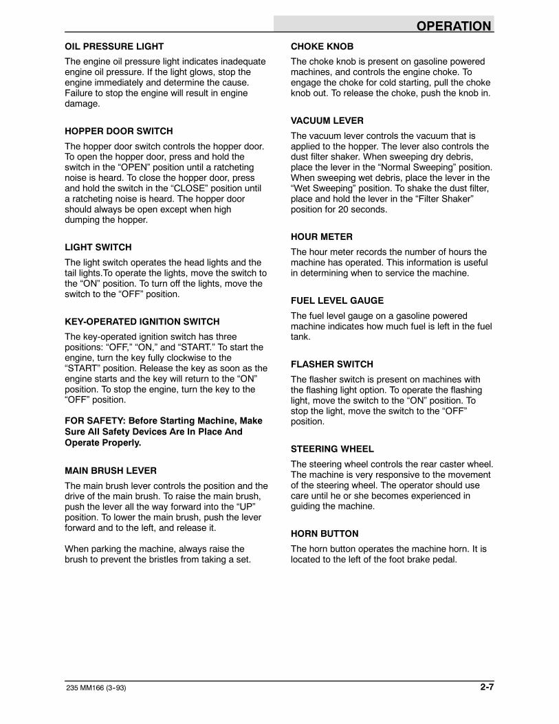
OIL PRESSURE LIGHT
The engine oil pressure light indicates inadequateengine oil pressure. If the light glows, stop theengine immediately and determine the cause.Failure to stop the engine will result in enginedamage.
HOPPER DOOR SWITCH
The hopper door switch controls the hopper door.To open the hopper door, press and hold theswitch in the “OPEN” position until a ratchetingnoise is heard. To close the hopper door, pressand hold the switch in the “CLOSE” position untila ratcheting noise is heard. The hopper doorshould always be open except when highdumping the hopper.
LIGHT SWITCH
The light switch operates the head lights and thetail lights.To operate the lights, move the switch tothe “ON” position. To turn off the lights, move theswitch to the “OFF” position.
KEY-OPERATED IGNITION SWITCH
The key-operated ignition switch has threepositions: “OFF,” “ON,” and “START.” To start theengine, turn the key fully clockwise to the“START” position. Release the key as soon as theengine starts and the key will return to the “ON”position. To stop the engine, turn the key to the“OFF” position.
FOR SAFETY: Before Starting Machine, MakeSure All Safety Devices Are In Place AndOperate Properly.
MAIN BRUSH LEVER
The main brush lever controls the position and thedrive of the main brush. To raise the main brush,push the lever all the way forward into the “UP”position. To lower the main brush, push the leverforward and to the left, and release it.
When parking the machine, always raise thebrush to prevent the bristles from taking a set.
CHOKE KNOB
The choke knob is present on gasoline poweredmachines, and controls the engine choke. Toengage the choke for cold starting, pull the chokeknob out. To release the choke, push the knob in.
VACUUM LEVER
The vacuum lever controls the vacuum that isapplied to the hopper. The lever also controls thedust filter shaker. When sweeping dry debris,place the lever in the “Normal Sweeping” position.When sweeping wet debris, place the lever in the“Wet Sweeping” position. To shake the dust filter,place and hold the lever in the “Filter Shaker”position for 20 seconds.
HOUR METER
The hour meter records the number of hours themachine has operated. This information is usefulin determining when to service the machine.
FUEL LEVEL GAUGE
The fuel level gauge on a gasoline poweredmachine indicates how much fuel is left in the fueltank.
FLASHER SWITCH
The flasher switch is present on machines withthe flashing light option. To operate the flashinglight, move the switch to the “ON” position. Tostop the light, move the switch to the “OFF”position.
STEERING WHEEL
The steering wheel controls the rear caster wheel.The machine is very responsive to the movementof the steering wheel. The operator should usecare until he or she becomes experienced inguiding the machine.
HORN BUTTON
The horn button operates the machine horn. It islocated to the left of the foot brake pedal.
OPERATION
235 MM166 (3--94)2-8
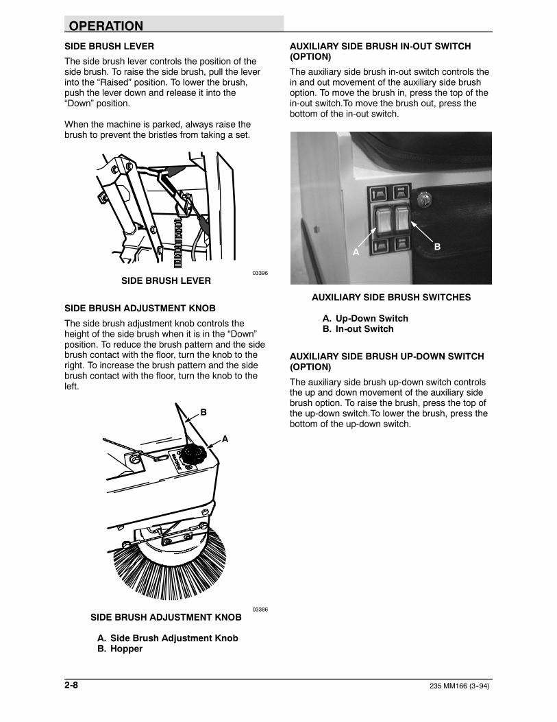
SIDE BRUSH LEVER
The side brush lever controls the position of theside brush. To raise the side brush, pull the leverinto the “Raised” position. To lower the brush,push the lever down and release it into the“Down” position.
When the machine is parked, always raise thebrush to prevent the bristles from taking a set.
03396
SIDE BRUSH LEVER
SIDE BRUSH ADJUSTMENT KNOB
The side brush adjustment knob controls theheight of the side brush when it is in the “Down”position. To reduce the brush pattern and the sidebrush contact with the floor, turn the knob to theright. To increase the brush pattern and the sidebrush contact with the floor, turn the knob to theleft.
B
A
03386
SIDE BRUSH ADJUSTMENT KNOB
A. Side Brush Adjustment KnobB. Hopper
AUXILIARY SIDE BRUSH IN-OUT SWITCH(OPTION)
The auxiliary side brush in-out switch controls thein and out movement of the auxiliary side brushoption. To move the brush in, press the top of thein-out switch.To move the brush out, press thebottom of the in-out switch.
BA
AUXILIARY SIDE BRUSH SWITCHES
A. Up-Down SwitchB. In-out Switch
AUXILIARY SIDE BRUSH UP-DOWN SWITCH(OPTION)
The auxiliary side brush up-down switch controlsthe up and down movement of the auxiliary sidebrush option. To raise the brush, press the top ofthe up-down switch.To lower the brush, press thebottom of the up-down switch.
OPERATION
2-9235 MM166 (5--91)
CIRCUIT BREAKERS
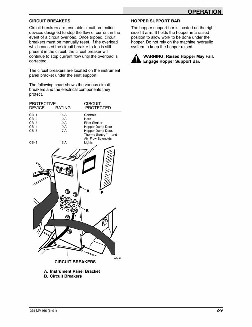
Circuit breakers are resetable circuit protectiondevices designed to stop the flow of current in theevent of a circuit overload. Once tripped, circuitbreakers must be manually reset. If the overloadwhich caused the circuit breaker to trip is stillpresent in the circuit, the circuit breaker willcontinue to stop current flow until the overload iscorrected.
The circuit breakers are located on the instrumentpanel bracket under the seat support.
The following chart shows the various circuitbreakers and the electrical components theyprotect.
PROTECTIVE CIRCUITDEVICE RATING PROTECTED
CB--1 15 A ControlsCB--2 10 A HornCB--3 10 A Filter ShakerCB--4 10 A Hopper Dump DoorCB--5 7 A Hopper Dump Door,
Thermo Sentryt andAir Flow Solenoids
CB--6 15 A Lights
A
B
03491
CIRCUIT BREAKERS
A. Instrument Panel BracketB. Circuit Breakers
HOPPER SUPPORT BAR
The hopper support bar is located on the rightside lift arm. It holds the hopper in a raisedposition to allow work to be done under thehopper. Do not rely on the machine hydraulicsystem to keep the hopper raised.
WARNING: Raised Hopper May Fall.Engage Hopper Support Bar.

OPERATION
235 MM166 (3--93)2-10
MACHINE OPERATION
NORMAL SWEEPING OPERATION
A normal sweeping operation consists of seventypical operations: pre-start checklist, startingmachine, sweeping, dumping hopper, postoperation checklist -- engine operating, stoppingmachine, and post operation checklist -- enginestopped.
The PRE-START CHECKLIST lists things tocheck before starting the machine.
TO START MACHINE lists the steps required tostart the machine.
TO SWEEP lists things to keep in mind beforeand during the sweeping operation.
TO DUMP HOPPER lists the steps required todump the hopper.
POST OPERATION CHECKLIST -- ENGINEOPERATING lists things to check before stoppingthe machine engine.
TO STOP MACHINE lists the steps required tostop the machine.
The POST OPERATION CHECKLIST -- ENGINESTOPPED lists things to check after stopping themachine engine.
PRE-START CHECKLIST
Check under the machine for leak spots.
Check the engine lubricating oil level.
Check the fuel level.
Check for LPG odor or frosting on hoses orcomponents indicating a leak.
Check the brakes and controls for properoperation.
Check the service records to determine servicerequirements.
TO START MACHINE
NOTE: Before starting machine, perform thepre-start checks.
1. LPG powered machines: Slowly open theLPG tank service valve.
NOTE: Opening the service valve too quickly maycause the service valve check valve to stop theflow of LPG fuel. If the check valve stops the flowof fuel, close the service valve, wait a fewseconds, and slowly open the valve once again.
2. The machine operator must be in theoperator’s seat with the directional pedal inthe “neutral” position and with a foot on thebrake pedal or with the parking brake set.
FOR SAFETY: Before Starting Machine; MakeSure All Safety Devices Are In Place AndOperate Properly, Check Brakes And SteeringFor Proper Operation.
3. Gasoline powered machines: When theengine is cold, pull out the choke knob aboutthree-fourths of the way. Push choke in afterthe engine has started and is runningsmoothly.
4. Gasoline powered machines: Move thethrottle control lever to the “IDLE” position.
LPG powered machines: Move the throttlecontrol lever to the “HIGH” position.
5. Turn the ignition switch key to the “START”position until the engine starts.
NOTE: Do not operate the starter motor for morethan 10 seconds at a time or after the engine hasstarted. Allow the starter to cool between startingattempts. The starter motor may be damaged if itis operated incorrectly.
6. Allow the engine and hydraulic system towarm up three to five minutes.
7. Release the machine parking brake.
8. Move the throttle control lever to the “FULL”position, and drive the machine to the areato be swept.

OPERATION
2-11235 MM166 (5--91)
TO SWEEP
Plan the sweeping in advance. Try to arrange longruns with minimum stopping and starting. Sweepdebris from very narrow aisles into main aislesahead of time. Do an entire floor or section at onetime. Overlap brush paths.
Pick up oversize debris before sweeping. Flattenor remove bulky cartons from aisles beforesweeping. Pick up pieces of wire, twine, string,etc., which could become entangled in brush orbrush plugs. Place large debris in hopper throughhopper inspection door.
Avoid turning the steering wheel too sharply whenthe machine is in motion. The machine is veryresponsive to the movement of the steeringwheel. Avoid sudden turns, except inemergencies.
Sweep as straight a path as possible. Avoidbumping into posts or scraping the sides of thesweeper.
1. Move the vacuum lever to the “NormalSweeping” position to sweep dry debris, or“Wet Sweeping” position to sweep wetdebris.
2. Push the main brush lever forward and tothe left, then release the lever to lower themain brush.
3. Move the side brush lever into the “Down”position.
4. Push the side brush and hopper lever intothe “ON” position.
5. Press and hold the hopper door switch in the“OPEN” position.
6. Sweep as required.
TO DUMP HOPPER
1. Push the main brush lever into the “UP”position.
2. Pull the side brush lever into the “Raised”position.
3. Move the vacuum lever to the “Filter Shaker”position for 20 seconds to shake the dustfilter.
4. Slowly drive the machine up to the dumpsite or dumpster.
5. Press and hold the hopper door switch in the“CLOSE” position.
6. Pull the side brush and hopper lever to the“LIFT” position, then into the “HOLD”position when at the desired dump height.
7. Press and hold the hopper door switch in the“OPEN” position to dump the hopper.
8. Press and hold the hopper door switch in the“CLOSE” position to close the hopper door.
9. Slowly back the machine away from thedump site or dumpster.
10. Push the side brush and hopper lever to the“LOWER” position to lower the hopper.
11. Press and hold the hopper door switch in the“OPEN” position to open the hopper door.
POST OPERATION CHECKLIST -- ENGINEOPERATING
Check brush patterns for width and evenness.
OPERATION
235 MM166 (3--93)2-12
TO STOP MACHINE
1. Return the directional pedal to the “neutral”position. Apply the brake.
2. Push the main brush lever into the “UP”position.
3. Pull the side brush lever back into the“Raised” position.
4. Pull the side brush and hopper lever into the“LOWER” position to stop the side brush.
5. Place the throttle control lever in the “IDLE”position.
6. Set the machine parking brake.
7. Turn the key-operated ignition switch key tothe “OFF” position. Remove the key fromthe ignition switch.
FOR SAFETY: Before Leaving Or ServicingMachine; Stop On Level Surface, Set ParkingBrake, Turn Off Machine And Remove Key.
8. LPG powered machines: Close the LPGtank service valve.
POST OPERATION CHECKLIST -- ENGINESTOPPED
Check the skirts for damage, wear, andadjustment.
Check for wire or string tangled on the brushes.
Check to make sure LPG tank service valve isclosed.
Check for LPG odor or frost on LPG hoses andcomponents, indicating a leak.
Check for leaks.
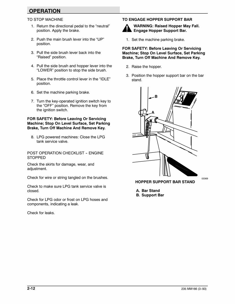
TO ENGAGE HOPPER SUPPORT BAR
WARNING: Raised Hopper May Fall.Engage Hopper Support Bar.
1. Set the machine parking brake.
FOR SAFETY: Before Leaving Or ServicingMachine; Stop On Level Surface, Set ParkingBrake, Turn Off Machine And Remove Key.
2. Raise the hopper.
3. Position the hopper support bar on the barstand.
B
A
03369
HOPPER SUPPORT BAR STAND
A. Bar StandB. Support Bar

OPERATION
2-13235 MM166 (5--91)
4. Slowly lower the hopper so the bar issecure.
A
B
03370
ENGAGED HOPPER SUPPORT BAR
A. Lift ArmB. Support Bar
TO DISENGAGE HOPPER SUPPORT BAR
1. Raise the hopper.
2. Place the support bar in its storage position.
3. Lower the hopper.
OPERATION ON GRADES
Drive the machine slowly on grades. Use thebrake pedal to control machine speed.
FOR SAFETY: When Using Machine, Go SlowOn Grades And Slippery Surfaces.
The maximum rated climb and descent angle is10_.

OPERATION
235 MM166 (5--91)2-14
MACHINE TROUBLESHOOTING
Problem Cause Remedy
Excessive dusting Dust skirts and seals worn,damaged, not adjusted properly
Replace or adjust skirts or seals
Dust filter clogged Shake and clean or replace filter
Vacuum hose damaged Replace vacuum hose
Vacuum fan failure Belt loose, broken or off sheave
Poor sweeping performance Brush bristles worn Replace brushes
Brushes not adjusted properly Adjust brushes
Debris caught in brush drivemechanism
Free mechanism of debris
Main brush drive failure Belt loose, broken or off sheave
Side brush drive failure See HYDRAULIC SYSTEMTROUBLESHOOTING: Sidebrush turns slowly or not at all
Hopper not adjusted properly Adjust hopper floor clearance
Hopper dump door closed Open dump door
Hopper full Empty hopper
Hopper floor skirts worn, damaged Replace skirts

OPERATION
2-15235 MM166 (5--91)
TRANSPORTING MACHINE
PUSHING OR TOWING MACHINE
The machine may be slowly pushed from the frontor rear, pushing on the bumper or the machineframe.
The machine may be slowly towed from the front.Use care when attaching towing cables or chainsto avoid damaging the machine.
MACHINE JACKING
The machine may be jacked up for service at thedesignated locations. Use a jack of adequatecapacity and good working condition. Always stopthe machine on a flat, level surface and block thetires before jacking the machine up.
The front jacking locations are on the flat bottomedge of the machine frame next to the front tires.The rear jacking location is the middle flat bottomedge of the rear bumper.
TO JACK UP MACHINE
1. Empty and lower the debris hopper.
2. Stop the engine and set the machineparking brake.
FOR SAFETY: Before Leaving Or ServicingMachine; Stop On Level Surface, Set ParkingBrake, Turn Off Machine And Remove Key.
3. Block the tires, which are not being jackedup, in order to secure the machine position.
FOR SAFETY: When Servicing Machine, BlockMachine Tires Before Jacking Machine Up.
4. Use a jack of adequate capacity to raise themachine. Jack up the machine only at thedesignated locations.
FOR SAFETY: When Servicing Machine, UseHoist Or Jack Of Adequate Capacity To LiftMachine, Jack Machine Up At DesignatedLocations Only. Block Machine Up With JackStands.
A03372
FRONT JACKING LOCATION
A. Jacking Location
A
03373
REAR JACKING LOCATION
A. Jacking Location
5. Block machine up with jack stands or similardevices in the designated locations tosecure the machine.
FOR SAFETY: When Servicing Machine, JackMachine Up At Designated Locations Only.Block Machine Up With Jack Stands.

OPERATION
235 MM166 (5--91)2-16
6. Lower the machine onto the jack stands.
7. Check to make sure the machine is secure.
8. Service the machine as required.
9. When finished servicing the machine, raisethe machine off the jack stands.
10. Remove the jack stands from under themachine.
11. Lower the machine.
12. Remove the blocks from the tires.
MACHINE TIE-DOWNS
The machine may be tied down at each corner ofthe main frame using the tie-down bracketssupplied in the tie-down kit.
A
03372
FRONT TIE-DOWN LOCATION
A. Tie-Down Bracket
When transporting the machine on a trailer or in atruck, be sure to set the machine parking brakeand block the machine tires to prevent themachine from rolling.

OPERATION
2-17235 MM166 (3--93)
MACHINE STORAGE
STORING MACHINE
When storing the machine for extended periods oftime, the following procedures must be followed tolessen the chance of rust, sludge, or otherundesirable deposits from forming.
1. Empty the debris hopper.
2. Change the engine oil.
3. Raise the main brush and side brush.
4. Park the machine on a level surface in acool, dry area.
5. Stop the engine and set the machineparking brake.
6. LPG powered machines: Close the LPGtank service valve. Remove and store LPGtank.
7. Fill the hydraulic reservoir with hydraulic fluidto prevent excessive condensation fromforming.
8. To store the machine 30 to 90 days:
A. Remove the spark plugs.
B. Pour 3 oz (90 cc) of clean engine oilinto each spark plug hole.
C. Remove the ignition coil high tensionwire. Operate the engine starter motorfor ten seconds. This distributes the oilover the cylinder walls.
NOTE: Before preparing the engine for storage,allow it to cool down to the surroundingtemperature. Oil adheres to cold metal surfacesmuch better than hot surfaces.
D. Replace the high tension coil wire andspark plugs.
E. Drain the gasoline from the carburetorbowl by removing the carburetoranti-diesel solenoid.
F. Replace the carburetor drain plug.
To store the machine 90 days to 6 monthsalso:
G. Seal the air cleaner inlet and theexhaust outlet with weatherproofmasking tape.
H. Tighten the engine oil filler cap, the fueltank cap, and the radiator cap to makecertain they are securely in place.

OPERATION
235 MM166 (5--91)2-18

MAINTENANCE
3-1235 MM166 (3--94)
SECTION 3CONTENTS
PageRECOMMENDED FIRST 50-HOUR
MACHINE INSPECTION 3-3. . . . . . . . . . . . .MAINTENANCE CHART 3-4. . . . . . . . . . . . . . . .LUBRICATION 3-6. . . . . . . . . . . . . . . . . . . . . . . . .
ENGINE 3-6. . . . . . . . . . . . . . . . . . . . . . . . . . .SIDE BRUSH LEVER PIVOT 3-6. . . . . . . . .REAR WHEEL SUPPORT BEARING 3-7. .STEERING LINKAGE 3-7. . . . . . . . . . . . . . . .
HYDRAULICS 3-8. . . . . . . . . . . . . . . . . . . . . . . . .HYDRAULIC FLUID 3-8. . . . . . . . . . . . . . . . .HYDRAULIC FLUID RESERVOIR 3-8. . . . .HYDRAULIC FILTER 3-8. . . . . . . . . . . . . . . .
TO REPLACE FILTER ELEMENT 3-9. .HYDRAULIC PUMPS 3-9. . . . . . . . . . . . . . . .
TO START AND BREAK-INHYDRAULIC PUMP 3-9. . . . . . . . . . . .
DIRECTIONAL PEDAL 3-10. . . . . . . . . . . . . . .TO ADJUST DIRECTIONAL
PEDAL LINKAGE 3-10. . . . . . . . . . . . . .LIFT ARM SPEED LIMITER 3-11. . . . . . . . . .HYDRAULIC FLUID LEAKS 3-12. . . . . . . . . .HYDRAULIC SCHEMATIC 3-13. . . . . . . . . . .HYDRAULIC SYSTEM
TROUBLESHOOTING 3-14. . . . . . . . . . . .HYDRAULIC COMPONENTS
TROUBLESHOOTING 3-15. . . . . . . . . . . .ENGINE 3-16. . . . . . . . . . . . . . . . . . . . . . . . . . . . . .
ENGINE LUBRICATION 3-16. . . . . . . . . . . . . .COOLING SYSTEM 3-16. . . . . . . . . . . . . . . . .AIR INTAKE SYSTEM 3-16. . . . . . . . . . . . . . .AIR FILTER 3-16. . . . . . . . . . . . . . . . . . . . . . . .
TO CLEAN OR REPLACE AIRFILTER ELEMENT 3-16. . . . . . . . . . . . .
FUEL SYSTEM, GASOLINE 3-17. . . . . . . . . .FUEL FILTER 3-17. . . . . . . . . . . . . . . . . . . .CARBURETOR 3-17. . . . . . . . . . . . . . . . . .
FUEL SYSTEM -- LPG 3-18. . . . . . . . . . . . . . .LPG FUEL SYSTEM 3-18. . . . . . . . . . . . . .FUEL TANKS 3-19. . . . . . . . . . . . . . . . . . . .TO CHANGE AN LPG FUEL TANK 3-20.FUEL FILTER LOCK 3-21. . . . . . . . . . . . . .VAPORIZER-REGULATOR 3-21. . . . . . . .CARBURETOR 3-21. . . . . . . . . . . . . . . . . .OIL PRESSURE SWITCH 3-21. . . . . . . . .
LPG FUEL TROUBLESHOOTING 3-21. . . . .ELECTRICAL SYSTEM 3-22. . . . . . . . . . . . . .
SPARK PLUG 3-22. . . . . . . . . . . . . . . . . . . .IGNITION SYSTEM 3-22. . . . . . . . . . . . . . .STARTER 3-22. . . . . . . . . . . . . . . . . . . . . . .
PageCYLINDER HEAD 3-22. . . . . . . . . . . . . . . . . . .
CYLINDER HEAD 3-22. . . . . . . . . . . . . . . .VALVE TAPPET CLEARANCE 3-23. . . . .CRANKCASE VENTILATION
SYSTEM 3-23. . . . . . . . . . . . . . . . . . . . .TUNE-UP CHART 3-23. . . . . . . . . . . . . . . . . . .
ELECTRICAL SYSTEM 3-24. . . . . . . . . . . . . . . . .BATTERY 3-24. . . . . . . . . . . . . . . . . . . . . . . . . .ELECTRICAL SCHEMATIC 3-25. . . . . . . . . . .ELECTRICAL SCHEMATIC,
AUXILIARY SIDE BRUSH 3-26. . . . . . . . . .BELTS AND CHAINS 3-27. . . . . . . . . . . . . . . . . . .
HYDRAULIC PUMP BELT 3-27. . . . . . . . . . . .TO REPLACE AND ADJUST
HYDRAULIC PUMP BELT 3-27. . . . . .VACUUM FAN BELT 3-27. . . . . . . . . . . . . . . . .
TO REPLACE AND ADJUSTVACUUM FAN BELT 3-27. . . . . . . . . . .
MAIN BRUSH BELT 3-29. . . . . . . . . . . . . . . . .TO REPLACE MAIN BRUSH BELT 3-29.
TAPER LOCK BUSHINGS 3-30. . . . . . . . . . . .TO REMOVE TAPER
LOCK BUSHING 3-30. . . . . . . . . . . . . .TO INSTALL TAPER
LOCK BUSHING 3-30. . . . . . . . . . . . . .STATIC DRAG CHAIN 3-30. . . . . . . . . . . . . . .
DEBRIS HOPPER AND DUST FILTER 3-31. . .DEBRIS HOPPER 3-31. . . . . . . . . . . . . . . . . . .
TO CHECK AND ADJUST HOPPERFLOOR CLEARANCE 3-31. . . . . . . . . .
THERMO SENTRYt 3-31. . . . . . . . . . . . . . . .TO CHECK THE
THERMO SENTRYt 3-31. . . . . . . . . .HOPPER DUST FILTER 3-32. . . . . . . . . . . . .
TO REMOVE AND REPLACEHOPPER DUST FILTER 3-33. . . . . . . .

MAINTENANCE
235 MM166 (8--95)3-2
PageBRUSHES 3-34. . . . . . . . . . . . . . . . . . . . . . . . . . . .
MAIN BRUSH 3-34. . . . . . . . . . . . . . . . . . . . . . .TO REMOVE MAIN BRUSH 3-34. . . . . . .TO INSTALL MAIN BRUSH 3-34. . . . . . . .TO CHECK AND ADJUST MAIN
BRUSH PATTERN 3-34. . . . . . . . . . . . .SIDE BRUSH 3-36. . . . . . . . . . . . . . . . . . . . . . .
TO REMOVE SIDE BRUSH 3-36. . . . . . . .TO INSTALL SIDE BRUSH 3-36. . . . . . . .
SKIRTS AND SEALS 3-37. . . . . . . . . . . . . . . . . . .BRUSH SKIRTS 3-37. . . . . . . . . . . . . . . . . . . .
TO REPLACE AND ADJUSTBRUSH SKIRTS 3-37. . . . . . . . . . . . . . .
REAR SKIRTS 3-37. . . . . . . . . . . . . . . . . . . . . .TO REPLACE AND ADJUST
REAR SKIRTS 3-37. . . . . . . . . . . . . . . .HOPPER LIP SKIRT 3-38. . . . . . . . . . . . . . . . .
TO REPLACE HOPPER LIP SKIRT 3-38.DUST SEALS 3-38. . . . . . . . . . . . . . . . . . . . . . .
TO REPLACE DUST SEALS 3-38. . . . . . .HOPPER DUMP DOOR SEAL 3-39. . . . . . . .
TO REPLACE HOPPER DUMPDOOR SEAL 3-39. . . . . . . . . . . . . . . . . .
VACUUM FAN SEAL 3-40. . . . . . . . . . . . . . . . .FILTER COVER SEAL 3-40. . . . . . . . . . . . . . .
BRAKES AND TIRES 3-41. . . . . . . . . . . . . . . . . . .BRAKES 3-41. . . . . . . . . . . . . . . . . . . . . . . . . . .TIRES 3-41. . . . . . . . . . . . . . . . . . . . . . . . . . . . .REAR WHEEL 3-41. . . . . . . . . . . . . . . . . . . . . .

MAINTENANCE
3-3235 MM166 (8--95)
RECOMMENDED FIRST 50-HOUR MACHINE INSPECTION
After the first 50 hours of operation, the followingprocedures are recommended:
1. Check the floor skirts to floor clearance.See SKIRTS AND SEALS.
2. Check the side brush and main brushpatterns. See BRUSHES.
3. Replace hydraulic fluid filter element.
4. Torque the rear wheel nuts in a star patternto 122 to 150 Nm (90 to 110 ft lb).See REAR WHEEL.
5. Perform all 50-hour interval lubrication andmaintenance procedures listed in theMAINTENANCE CHART.

MAINTENANCE
235 MM166 (3--94)3-4
MAINTENANCE CHART
13
7
16
13
15 4
14
8
11
10
98654321
17
12
18
03488
No. ofService
Interval Key Description Procedure Lubricant Points
Daily 1 Engine Check oil level EO 14 Brush and rear skirts Check for damage and wear -- 418 Hopper lip skirt Check for damage and wear -- 15 Main brush Check for damage and wear -- 111 Side brush Check for damage and wear -- 1
25 Hours 1 Engine Clean air filter precleaner -- 1Change oil and oil filter EO 1Clean cooling fins -- 1
50 Hours 5 Main brush Rotate end-for-end -- 1

MAINTENANCE
3-5235 MM166 (8--95)
No. ofService
Interval Key Description Procedure Lubricant Points
100 Hours 1 Engine Clean or replace spark plugs -- 2Clean or replace dry-type air -- 1filter element
3 Dust Seals Check for damage and wear -- 69 Dust filter Clean or replace -- 115 Hydraulic reservoir Check fluid level HYDO 110 Thermo Sentryt Test -- 117 Rear tire Check pressure and wear -- 18 Front tires Inspect for wear -- 2
200 Hours 1 Engine Clean breather valve -- 1Check crankcase ventilation -- 4hoses, tubes and fittings
6 Vacuum fan belt Check tension -- 12 Hydraulic pump belt Check tension -- 112 Side brush lever pivot Lubricate SPL 114 Parking brake Check adjustment -- 116 Rear wheel support Lubricate SPL 1
bearing13 Steering linkage Lubricate SPL 2
400 Hours 1 Engine Check and adjust idle speed -- 1Clean carbon deposits -- 2Check valve clearance -- 4Check starter motor brushes -- 1
15 Hydraulic fluid reservoir Change hydraulic fluid HYDO 17 Hydraulic fluid filter Change filter element -- 1
800 Hours 17 Rear wheel Torque wheel nuts -- 1
EO -- Engine oilHYDO -- TENNANT or approved hydraulic fluidSPL -- Special lubricant, Lubriplate EMB grease (TENNANT part number 01433--1)
NOTE: More frequent intervals may be required in extremely dusty conditions.

MAINTENANCE
235 MM166 (3--94)3-6
LUBRICATION
ENGINE
Check the engine oil level daily.
Change the engine oil and oil filter after every 25hours of operation. Use a straight SAE 30-weight,API class SF engine oil. If multiviscosity oil isused, oil consumption and combustion depositswill increase. Using other than API class SF oil orextending oil change intervals could cause enginedamage not covered by the engine warranty. Theengine oil capacity is 1.7 qt (1.6 L).
SIDE BRUSH LEVER PIVOT
The side brush lever pivot allows the side brushlever to move freely. Lubricate the pivot withLubriplate EMB grease (TENNANT part number01433--1) after every 200 hours of operation.
A
B
03396
SIDE BRUSH LEVER PIVOT
A. Side Brush LeverB. Pivot

MAINTENANCE
3-7235 MM166 (5--91)
REAR WHEEL SUPPORT BEARING
The rear wheel support bearing allows the rearwheel assembly to rotate freely. It is lubricatedwith Lubriplate EMB grease (TENNANT partnumber 01433--1). Apply the lubricant with a handgrease gun after every 200 hours of operation.
A
B
C
03501
REAR WHEEL SUPPORT BEARING
A. Rear Wheel SupportB. Support Grease FittingC. Rear Steering Link Grease Fitting
STEERING LINKAGE
The steering linkage controls machine steering. Agrease fitting is located on each of the two linkageball joints for lubrication. The linkage should belubricated by applying Lubriplate EMB grease(TENNANT part number 01433--1) to the greasefittings after every 200 hours of operation.
A
B
03394
FRONT STEERING LINK
A. Steering LinkB. Grease Fitting

MAINTENANCE
235 MM166 (3--94)3-8
HYDRAULICS
HYDRAULIC FLUID
The quality and condition of the hydraulic fluidplay a very important role in how well the machineoperates. TENNANT’s hydraulic fluid is speciallyselected to meet the needs of TENNANTmachines.
TENNANT’s hydraulic fluids provide a longer lifefor the hydraulic components. There is onerecommended fluid.
TENNANT part no. Fluid Weight65870 5--20W
If a locally-available hydraulic fluid is used, makesure the specifications match TENNANT hydraulicfluid specifications. Using substitute fluids cancause premature failure of hydraulic components.
European marketed machines are filled withlocally available hydraulic fluids. Check the labelon the hydraulic fluid reservoir.
ATTENTION! Hydraulic components dependon system hydraulic fluid for internallubrication. Malfunctions, accelerated wear,and damage will result if dirt or othercontaminants enter the hydraulic system.
HYDRAULIC FLUID RESERVOIR
Hydraulic fluid is stored in the hydraulic fluidreservoir. It holds 3.9 gal (14.8 L) of hydraulicfluid. The reservoir is located under the seatsupport.
The fluid level is checked by looking at thedipstick on the breather-filler cap with the hopperin the sweeping position. The reservoir is fullwhen the fluid level is above the “ADD” mark onthe dipstick.
A
B
03502
HYDRAULIC FLUID RESERVOIR
A. ReservoirB. Breather-Filler Cap
Check the hydraulic fluid level at operatingtemperature every 100 hours of operation.Change the hydraulic fluid after every 400 hoursof operation. Do not overfill the hydraulic fluidreservoir. Hydraulic fluid expands as it heats to itsnormal operating temperature. Always allow forexpansion when filling the reservoir. Lubricate thefiller cap gasket with a film of hydraulic fluidbefore putting the cap back on the reservoir.
HYDRAULIC FILTER
The hydraulic fluid filter keeps the machinehydraulic system clean to a level of 10 microns.The hydraulic fluid filter is located next to thevacuum fan.
Replace the hydraulic fluid filter element after thefirst 50 hours of operation and then after every400 hours of operation.

MAINTENANCE
3-9235 MM166 (5--91)
TO REPLACE FILTER ELEMENT
1. Stop the engine and set the machineparking brake.
FOR SAFETY: Before Leaving Or ServicingMachine; Stop On Level Surface, Set ParkingBrake, Turn Off Machine And Remove Key.
2. Open the seat support.
A
03395
HYDRAULIC FLUID FILTER
A. Filter Element
3. Unthread and discard the hydraulic fluid filterelement.
4. Apply a thin coat of hydraulic fluid to the sealof the new hydraulic fluid filter element.
5. Thread and hand tighten the new hydraulicfluid filter element on the filter head.
6. Close the seat support.
7. Operate the machine and check for leaks.Correct any leaks found.
8. Check the hydraulic fluid reservoir level andfill as required.
HYDRAULIC PUMPS
The machine propelling pump is a variabledisplacement hydraulic piston pump. It is drivenby the engine via a dual belt.
The machine accessories pump is a hydraulicgear pump. It is driven by a belt from thepropelling pump sheave.
After repairing or replacing a hydraulic pump, orwhen system contamination is likely, change thehydraulic fluid in the reservoir and the hydraulicfluid filter. Then the proper start and break-inprocedure must be followed to prevent possibledamage to the pump. Replace the hydraulic fluidfilter after the first hour of operation. TO STARTAND BREAK-IN HYDRAULIC PUMP outlines theprocedure.
TO START AND BREAK-IN HYDRAULIC PUMP
1. Stop the engine, set the machine parkingbrake and block the front tires of themachine.
FOR SAFETY: Before Leaving Or ServicingMachine; Stop On Level Surface, Set ParkingBrake, Turn Off Machine And Remove Key.
2. Jack up the rear of the machine at thedesignated locations.
FOR SAFETY: When Servicing Machine, BlockMachine Tires Before Jacking Machine Up.
3. Block up the machine with jack stands in thedesignated locations. Make sure the rear tireclears the floor by 2 in (50 mm) and allobstacles within a 24 in (610 mm) radius.
FOR SAFETY: When Servicing Machine, JackMachine Up At Designated Locations Only.Block Machine Up With Jack Stands.
4. Fill the hydraulic fluid reservoir with 3 gal(11 L) of new, approved hydraulic fluid.
5. Fill the hydraulic pump through the casedrain port with hydraulic fluid.
6. Remove the engine coil wire from the enginedistrinbutor or turn off fuel flow.
7. Operate the engine starter motor for three10 second periods.
MAINTENANCE
235 MM166 (5--91)3-10
8. Replace the engine coil wire.
9. Start the engine and operate it at an idle fortwo minutes.
10. Press the directional pedal one-half of itstravel in the “forward” direction while alsooperating the main brush and side brush forone minute.
11. Adjust the directional pedal as described inTO ADJUST DIRECTIONAL PEDALLINKAGE.
12. Stop the engine.
13. Raise the rear of the machine, remove thejack stands, and lower the machine.
14. Fill the hydraulic fluid reservoir with new,approved hydraulic fluid.
15. Check the hose routings to be sure thehoses do not contact any moving, hot, orsharp surfaces.
16. Replace the hydraulic fluid filter after the firsthour of operation.
DIRECTIONAL PEDAL
The directional pedal controls the flow of hydraulicfluid to the hydraulic drive motor. The pedal hasthree positions -- ”forward,” “neutral,” and“reverse.” The “forward” and “reverse” positionssend hydraulic fluid to the drive motor to propelthe machine.
The “neutral” position is the position in which thepropelling pump sends no hydraulic fluid to thepropelling motor. The machine should not creepwhen the “neutral” position is correctly adjusted.Adjust the pedal linkages, as described inTO ADJUST DIRECTIONAL PEDAL LINKAGE,whenever the machine creeps or after replacingthe hydraulic propelling pump or pump linkages.The pedal linkages should also be adjustedwhenever the reverse speed is excessive orinadequate.
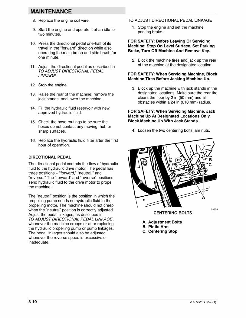
TO ADJUST DIRECTIONAL PEDAL LINKAGE
1. Stop the engine and set the machineparking brake.
FOR SAFETY: Before Leaving Or ServicingMachine; Stop On Level Surface, Set ParkingBrake, Turn Off Machine And Remove Key.
2. Block the machine tires and jack up the rearof the machine at the designated location.
FOR SAFETY: When Servicing Machine, BlockMachine Tires Before Jacking Machine Up.
3. Block up the machine with jack stands in thedesignated locations. Make sure the rear tireclears the floor by 2 in (50 mm) and allobstacles within a 24 in (610 mm) radius.
FOR SAFETY: When Servicing Machine, JackMachine Up At Designated Locations Only.Block Machine Up With Jack Stands.
4. Loosen the two centering bolts jam nuts.
A
CB
03505
CENTERING BOLTS
A. Adjustment BoltsB. Pintle ArmC. Centering Stop

MAINTENANCE
3-11235 MM166 (5--91)
5. Start the engine.
6. Move the directional pedal into the “forward”position and release it. The rear wheelshould stop rotating as soon as the pedal isreleased. Stop the engine and adjust thecentering bolt as required.
7. Move the directional pedal into the “reverse”position and release it. The rear wheelshould stop rotating as soon as the pedal isreleased. Stop the engine and adjust thecentering bolt as required.
NOTE: If there is not enough adjustment in thecentering bolts, reposition the centering stop.
8. Tighten the jam nuts.
9. Raise the rear of the machine, remove thejack stands, and lower the machine.
10. Adjust the position of the directional pedalball joints so the pedal hits the floor whenthe directional pedal is pressed backward.The backward travel should be restricted sothe machine will not travel faster than 3 mph(5 km/h) in reverse.
11. Tighten the directional pedal ball joints andjam nuts.
LIFT ARM SPEED LIMITER
The lift arm speed limiter limits the forward speedthe machine can travel when the hopper is raised.The speed limiter should be adjusted wheneverthe pump control linkage is adjusted. Themachine should travel 2 mph (3 km/h) with thehopper raised.
The speed limiter consists of a cam under thedirectional pedal with a link to the lift arms. Whenthe hopper is raised, the link lifts the cam underthe pedal. This limits how far the directional pedalcan be pressed, limiting the machine speed.
To adjust the limited speed, raise the hopper andengage the hopper support bar. Loosen the twobracket bolts and slide the bracket and camforward to increase speed or slide the bracketbackward to decrease speed. Tighten the bolts.
A
B
03507
SPEED LIMITER LINK
A. Bracket and CamB. Bracket Bolts

MAINTENANCE
235 MM166 (5--91)3-12
HYDRAULIC FLUID LEAKS
Fluid escaping from a very small hole can bealmost invisible. Use a piece of cardboard orwood, rather than hands, to search for suspectedleaks.
A
B
C
00002
HYDRAULIC PINHOLE LEAK
A. CardboardB. Pinhole LeakC. Magnifying Glass
If injured by escaping hydraulic fluid, see a doctorat once. Serious infection or reaction can developif proper medical treatment is not administeredimmediately.
FOR SAFETY: When Servicing Machine, UseCardboard To Locate Leaking Hydraulic FluidUnder Pressure.

MAINTENANCE
3-13235 MM166 (3--94)
03460
HYDRAULIC SCHEMATIC

MAINTENANCE
235 MM166 (5--91)3-14
HYDRAULIC SYSTEM TROUBLESHOOTING
Problem Cause Remedy
Machine travels slowly or nott ll
Parking brake set Release parking brakeat all Control linkage broken or not
adjusted properlyReplace and/or adjust linkage
Relief valve stuck open (leaking)valve
Clean or replace relief valve -- oneforward, one reverse
Motor failure See HYDRAULIC COMPONENTSTROUBLESHOOTING: Hydraulicmotor failure
Pump failure See HYDRAULIC COMPONENTSTROUBLESHOOTING: Hydraulicpiston pump failure
Hydraulic fluid level low Fill hydraulic fluid reservoir
Side brush turns slowly or notat all
Hydraulic control valve failure See HYDRAULIC COMPONENTSTROUBLESHOOTING: Hydrauliccontrol valve failure
Hydraulic motor failure See HYDRAULIC COMPONENTSTROUBLESHOOTING: Hydraulicmotor failure
Relief valve in control valvesticking
Clean or replace relief valve
Gear pump failure See HYDRAULIC COMPONENTSTROUBLESHOOTING: Hydraulicgear pump failure
Hopper will not lift Hydraulic control valve failure See HYDRAULIC COMPONENTSTROUBLESHOOTING: Hydrauliccontrol valve failure
Hydraulic orifice at lift cylinderplugged
Replace orifice
Lift cylinder failure See HYDRAULIC COMPONENTSTROUBLESHOOTING: Hydrauliccylinder failure
Gear pump failure See HYDRAULIC COMPONENTSTROUBLESHOOTING: Hydraulicgear pump failure
Hopper overloaded Empty hopper
Lift arms binding Replace and/or adjust lift armlinkage
Hopper will not lower Lift cylinder failure See HYDRAULIC COMPONENTSTROUBLESHOOTING: Hydrauliccylinder failure
Lift arms binding Replace and/or adjust lift armlinkage
Hydraulic orifice at lift cylinderplugged
Replace orifice

MAINTENANCE
3-15235 MM166 (5--91)
HYDRAULIC COMPONENTS TROUBLESHOOTING
Problem Cause Remedy
Hydraulic cylinder failure Piston seals leaking Install seal kit
Barrel worn or rod bent Replace cylinder rod
Hydraulic control valve failure Valve seals leaking Install seal kit
Relief valve stuck open (leaking) Clean or replace relief valve
Hydraulic motor failure Motor leaking Install seal kit
Drive link failure Replace drive link
Gerotor worn Replace gerotor set
Output shaft failure Replace output shaft and bearings
Hydraulic gear pump failure Pump leaking Install seal kit
Gear set failure Replace gear set
Shaft failure Replace gear set
Hydraulic piston pump failure Pump leaking Install seal kit
Relief valve stuck Clean or replace relief valve
Integral charge pump failure Replace charge pump
Rotating group worn Replace rotating group
Shaft failure Replace shaft
Backplate worn Replace backplate
Engine-to-pump coupling failure Replace coupling

MAINTENANCE
235 MM166 (3--93)3-16
ENGINE
ENGINE LUBRICATION
Check the engine oil level daily.
Change the engine oil and oil filter after every50 hours of operation. Use a straight SAE30-weight, API class SF engine oil. Ifmultiviscosity oil is used, oil consumption andcombustion deposits will increase.
Using other than API class SF oil or extending oilchange intervals could cause engine damage notcovered by the engine warranty.
The engine oil capacity is 1.7 qt (1.6 L).
A
B
03510
DIPSTICK AND FILL CAP
A. DipstickB. Fill Cap
COOLING SYSTEM
Maintaining cooling system efficiency is important.Engine temperatures must be brought up to andmaintained within the satisfactory range forefficient operation. However, the engine must bekept from overheating in order to prevent damageto the valves, pistons, and bearings.
Clean the engine cooling fins after every 50 hoursof operation.
FOR SAFETY: When Servicing Machine, WearEye And Ear Protection When UsingPressurized Air Or Water.
AIR INTAKE SYSTEM
The importance of maintaining an air filter inproper condition cannot be overemphasized. Dirtinduced through improperly installed, improperlyserviced, or inadequate air filter elements wearsout more engines than long hours of operation.Even a small amount of dirt will wear out a set ofpiston rings in just a few hours. Operating with aclogged air filter element also causes the fuelmixture to be richer, which can lead to formationof harmful sludge deposits in the engine. Alwayscover the air intake when the air cleaner isremoved for servicing. Do not neglect servicingthe air cleaner. Use only correct parts forreplacement. Keep all other air intakecomponents such as hoses, clamps, etc., secureand in good condition to prevent entrance ofunfiltered air.
AIR FILTER
The engine air filter is made up of two parts, afoam precleaner and a dry cartridge-type filter.The foam precleaner must be cleaned andre-oiled after every 25 hours of operation. The drycartridge-type filter should be cleaned or replacedafter every 100 hours of operation. The filterelement must be replaced if it is damaged or hasbeen cleaned three times.
TO CLEAN OR REPLACE AIR FILTERELEMENT
1. Stop the engine and set the machineparking brake.
FOR SAFETY: Before Leaving Or ServicingMachine; Stop On Level Surface, Set ParkingBrake, Turn Off Machine And Remove Key.
2. Open the seat support.
3. Remove the air filter cover wing nut.
4. Remove the air filter cover.

MAINTENANCE
3-17235 MM166 (5--91)
5. Remove the foam precleaner.
A
B
03495
REMOVING ENGINE AIR FILTER
A. Foam PrecleanerB. Dry Cartridge-Type Air Filter
6. Wash the foam precleaner in liquiddetergent and water.
7. Squeeze it dry in a cloth.
8. Remove the dry cartridge-type filter nut andcup.
9. Gently remove the dry cartridge-type airfilter.
10. Clean or discard the dry cartridge-type airfilter.
11. Clean the interior of the air cleaner housingwith a damp cloth. Clean the elementsealing surfaces.
12. Position the cleaned or new, drycartridge-type air filter on the engine.
13. Slide the air filter cup over the air filter stud.
14. Thread and tighten the nut onto the air filterstud.
15. Oil the foam precleaner with 1 oz (30 cc) ofclean engine oil. Squeeze the precleaner todistribute the oil evenly throughout the foam.
16. Slide the foam precleaner over the drycartridge-type filter.
17. Position the air filter cover over the air filterassembly. Tighten the wing nut on the airfilter stud.
FUEL SYSTEM, GASOLINE
FUEL FILTER
An in-line fuel filter has been provided to filter thefuel. The filter is located next to the fuel tank. Thesystem is also equipped with a fuel shutoff valve.
Replace the filter when necessary.
CARBURETOR
The carburetor idle speed should be checked andadjusted after every 400 hours of operation. Earlymachines had an idle and a main fuel valve. Latermachines only have an idle fuel valve.
The initial setting of the idle fuel needle valve ismade by lightly turning it all the way in, thenturning it out one-half turn. Final adjustment ismade with the engine running and warm.

MAINTENANCE
235 MM166 (5--91)3-18
The initial setting of the main fuel needle valve, ifit is present, is made by lightly turning it all theway in, then turning it out two and three-quarterturns. The fuel tank should be approximatelyone-half full and with the engine running atapproximately 2200 RPM. Final adjustment ismade with the engine warm. Turn the main fueladjusting needle valve out until the engine beginsto lose speed (rich). Note the position of theneedle. Then turn the needle in. The enginespeed may increase, then it will decrease as theneedle is turned in (lean). Note the position of theneedle. Set the needle half way between the richand lean positions.
B
A
03496
CARBURETOR ADJUSTMENTS
A. Idle Needle ValveB. Main Fuel Needle Valve
FUEL SYSTEM -- LPG
LPG FUEL SYSTEM
The LPG fuel system is made up of sixcomponents which are: the LPG fuel tank,pressure relief valve, fuel filter lock,vaporizer-regulator, secondary regulator, and thecarburetor.
Liquid LPG fuel flows from the LPG tank, under itsown pressure, to the pressure relief valve. Thisvalve is normally closed, preventing LPG fuel fromescaping into the atmosphere. The valve opens torelieve pressure if the fuel pressure exceedssystem limits. From the pressure relief valve, theLPG fuel is piped to the fuel filter lock. The fuelfilter lock filters unwanted tank scale and depositsout of the LPG fuel. The fuel filter lock also stopsthe flow of LPG fuel when the engine is notoperating. The oil pressure switch controls thefuel filter lock. When the engine oil pressure is 4psi (30 kPa) or greater, the oil pressure switchpermits an electrical current to open the fuel filterlock which allows LPG fuel to flow on to thevaporizer, then the regulator. The oil pressureswitch is bypassed when the engine is beingstarted, allowing LPG fuel to flow.
The vaporizer converts the LPG fuel into agaseous LPG fuel. Within the vaporizer, thegaseous LPG fuel is sent to the primary regulator.The primary regulator section reduces thepressure of the LPG fuel. From the primaryregulator section of the vaporizer, the LPG fuel issent to the secondary regulator. The secondaryregulator reduces the LPG fuel pressure to thelevel required by the carburetor. Then the fuel issent to the carburetor where it is finally meteredinto the air flow which is sent to the enginecombustion chamber.
A B CD
E
F
GH
04232
LPG FUEL SYSTEM
A. CarburetorB. Secondary RegulatorC. Vaporizer-RegulatorD. Fuel Filter LockE. Pressure Relief ValveF. Tank Service ValveG. LPG Fuel TankH. Oil Pressure Switch

MAINTENANCE
3-19235 MM166 (5--91)
Never operate an LPG powered machine if theLPG fuel system is leaking, or if any component inthe fuel system is malfunctioning. Operating themachine under either of these conditions maycause a fire or explosion.
Check for frosting. If frosting occurs on or nearany LPG component, there is a possibility of anLPG fuel leak or a malfunctioning component. Tolocate the leak, apply a soapy water solution tothe suspected area. Watch for bubbles forming inthe suspected area. This area may have an LPGfuel leak. Repair or replace the part. Use Loctitebrand Stainless Steel PST thread sealant whenreassembling. This epoxy-type sealant is notaffected by aging or high humidity. Be sure tofollow application directions and apply propertorque when reconnecting fittings. Never bypasssafety components except to test. If the safetycomponents are defective, replace them beforeoperating the machine.
Check routings of all LPG hoses. Keep themaway from sharp edges, exhaust manifolds, orother hot surfaces. Check for signs of abrasion ordeterioration. Replace hoses found to be worn ordamaged.
FUEL TANKS
The LPG fuel tanks should be inspected for sharpdents, gouges, leaks, and broken protecting ringswhenever the tanks are refilled. All tank valvesmust be inspected for leaks using a soap solution.Valves must also be checked for dirt, paint, orother debris in the valve openings. The followingspecific checks must also be made:
Filler Valve -- Check for proper functioning and thepresence of the handwheel. Valve must be closedexcept during filling.
Vapor and Liquid Service Valves -- Check forproper functioning and presence of thehandwheel. The valve must be closed exceptwhen in service.
Tank Service Valve Coupling -- Check for properfunctioning, thread condition, and damaged ormissing washers or o-rings.
Safety Relief Valve -- Check for damage. Checkfor the presence of the relief valve elbow and theproper direction of the elbow. If the rain cap ismissing, check for foreign matter and replace therain cap. Do not tamper with the relief valvesetting.
Magnetic Liquid Level Gauge -- Check operationagainst the maximum filling point as determinedby weight.
A
B
C
D
00115
TYPICAL LPG VAPOR WITHDRAWAL FUELTANK
A. Filler ValveB. Safety Relief ValveC. Vapor Service ValveD. Liquid Level Gauge
An LPG fuel tank with any of the stated defectsmust be removed from service and be repaired ordestroyed accordingly.
If an LPG fuel tank is damaged or leaking, itshould be removed to a designated safe area,and the proper personnel should be notified. Donot attempt to make repairs to the tank,regardless of condition. Repairs or disposal mustonly be made by qualified personnel.

MAINTENANCE
235 MM166 (3--93)3-20
The care an LPG fuel tank receives has a directbearing on how long that tank can be used safely.LPG fuel tanks must not be dropped or draggedacross any surface. To move LPG fuel tanks, usea hand truck or roll the tank on its foot ring while itis being held in a position slightly off vertical.
Whether the storage is inside or outside, fueltanks should not be stored in the vicinity ofcombustible materials or high temperaturesources such as ovens and furnaces, since theheat may raise the pressure of the fuel to a pointwhere the safety relief valves would function. Takecare to insure that the tanks are stored in such away that if the safety relief valves do function,they will relieve vapor, rather than liquid.
Valves on empty tanks must be closed duringstorage and transportation.
Similar precautions should be taken in storingmachines fitted with LPG fuel tanks. Themachines may be stored or serviced insidebuildings, provided there are no leaks in the fuelsystem and the tanks are not overfilled. Whilemachines are being repaired inside a building, theshut-off valve on the tank must be closed, exceptwhen the engine must be operated.
Changing the tank is a chance for the machineoperator to carefully observe the tank, fittings, andthe fuel lines and fittings. If abnormal wear isdetected, the operator should report the findingsto the appropriate personnel.
TO CHANGE AN LPG FUEL TANK
1. Park the machine in a designated safe area.Set the machine parking brake.
FOR SAFETY: Before Leaving Or ServicingMachine; Stop On Level Surface, Set ParkingBrake, Turn Off Machine And Remove Key.
2. Close the tank service valve.
3. Operate the engine until it stops from lack offuel.
FOR SAFETY: When Servicing Machine, KeepFlames And Sparks Away From Fuel SystemService Area. Keep Area Well Ventilated.
4. Put on gloves and remove thequick-disconnect tank coupling.
5. Inspect the LPG fuel lines for wear ordamage.
6. Remove the empty LPG fuel tank from themachine.
7. Check the tank for damage or wear.
8. Store the tank in a designated safe area.
9. Select a filled LPG fuel tank and inspect itfor damage or leaks.
NOTE: Make sure the LPG fuel tank matches thefuel system (vapor tank with vapor system).
10. Carefully place the LPG tank in the machineso that the tank centering pin enters thealigning hole in the tank collar.
NOTE: If the pin cannot be engaged, make sureyou have the correct LPG fuel tank and thenadjust the mounting bracket up or down.
11. Fasten the tank hold-down clamp to lock thetank in position.
12. Connect the LPG fuel line to the tankservice coupling. Make sure the servicecoupling is clean and free of damage. Alsomake sure it matches the machine servicecoupling.
13. Open the tank service valve slowly andcheck for leaks. If an LPG leak is found,close the service valve immediately andnotify the appropriate personnel.
14. If no leaks are found, the engine is ready tostart.

MAINTENANCE
3-21235 MM166 (5--91)
FUEL FILTER LOCK
The fuel filter lock filters the LPG fuel. It alsostops the flow of LPG fuel to the engine when theengine is not operating or when the engine oilpressure is less than 4 psi (30 kPa).
Replace the filter pack with the filter packreplacement kit if diminished gas flow indicatesthe filter is clogged. A drain plug is provided forpurging the filter bowl. Clean out the bowl whenreplacing the filter pack.
VAPORIZER-REGULATOR
nIf any malfunction is noted, completelydisassemble the vaporizer-regulator. Clean all ofthe parts in alcohol. Inspect all of the parts andreplace where needed. Carefully reassemble thevaporizer-regulator with the seal repair kit. Checkfor proper operation.
CARBURETOR
If any malfunction is noted, completelydisassemble the carburetor. Clean all of the partsin alcohol.
Inspect all of the parts and replace when needed.Carefully reassemble the carburetor with the sealrepair kit.
OIL PRESSURE SWITCH
The engine oil pressure switch requires no regularmaintenance. Never bypass the oil pressureswitch as this is a safety feature which preventsLPG fuel from flowing when the engine is notoperating properly.
LPG FUEL TROUBLESHOOTING
Problem Cause Remedy
Engine will not start Out of fuel Replace fuel tank with full one
Service valve opened too quickly-- engaging safety valve
Close valve and reopen slowly
Plugged fuel filter Replace filter
Kinked or restricted fuel line Straighten or replace fuel line
Engine out of tune Tune-up engine
Oil pressure switch failure Replace oil pressure switch
Fuel lock valve failure Repair or replace fuel filter lock
Vaporizer-regulator failure Repair or replace vaporizer-regu-lator
Engine runs unevenly or lackspower
Wrong type of fuel tank Replace with either vapor or liquidwithdrawal tank for proper systemp
Plugged fuel filter Replace filter
Kinked or restricted fuel line Straighten or replace fuel line
Engine out of tune Tune-up engine
Restricted air filter Clean or replace air filter element
Vaporizer-regulator maladjusted Adjust vaporizer-regulator

MAINTENANCE
235 MM166 (8--95)3-22
ELECTRICAL SYSTEM
SPARK PLUG
Clean or replace, and adjust spark plugs after100 hours of operation. A wire gauge is best forchecking the spark plug gap. A flat gauge shouldnot be used unless the electrode surfaces havebeen dressed with a small file to get parallelsurfaces between the center and side electrodes.Set the spark plug gap by bending the sideelectrode. All spark plugs, new or used, shouldhave the gaps checked and reset if necessary.
AB
03559
GAPPING THE SPARK PLUG
A. Spark PlugB. Gapping Tool
The proper spark plug gap is 0.025 in (0.6 mm)for gasoline engines. The proper spark plug gap is0.018 in (0.4 mm) for LPG engines.
IGNITION SYSTEM
The engine ignition system is the breakerlesstype. The ignition system needs no regularmaintenance. The only adjustment is the ignitionair module gap which should be set at 0.008 to0.012 in (0.2 to 0.3 mm).
STARTER
The starter motor brushes must be inspected afterevery 400 hours of operation.
CYLINDER HEAD
CYLINDER HEAD
The cylinder head may develop carbon deposits.After every 400 hours of operation, remove thecylinder head and clean it of any accumulateddeposits. Replace the cylinder head, making surethe cylinder head screws are lubricated withgraphite grease and are returned to the samehole. Alternately snug the screws; tighten them toone-half of the specified value, then torque thescrews to 15 to 20 ft lb (20 to 25 Nm).
3
7
5
81
26
4
9
03497
CYLINDER HEAD SCREW TIGHTENINGSEQUENCE

MAINTENANCE
3-23235 MM166 (8--95)
VALVE TAPPET CLEARANCE
The valve tappet clearance should be checkedafter every 400 hours of operation. The intakevalve clearance should be 0.003 to 0.006 in(0.07 to 0.15 mm) cold.
The exhaust valve clearance for engines serialnumbers up to 1816500655 should be 0.016 to0.019 in (0.40 to 0.50 mm) cold.
The exhaust valve clearance for engines serialnumber 1816500656 to 1917809295 should be0.011 to 0.014 in (0.25 to 0.35 mm) cold.
The exhaust valve clearance for engines serialnumber 1917809296 and above should be 0.013to 0.016 in (0.35 to 0.40 mm) cold.
Grind off the end of the valve stem to obtain theproper clearance.
CRANKCASE VENTILATION SYSTEM
Clean the crankcase ventilation hoses, tubes, andfittings after every 200 hours of operation.
TUNE-UP CHART
Idle speed 1000 rpm
Maximum governedspeed
2200 rpm
Spark plug gap,gasoline
0.025 in (0.6 mm)
Spark plug gap, LPG 0.018 in (0.4 mm)
Valve clearances, coldintake
0.003 to 0.006 in(0.07 to 0.15 mm)
Valve clearances, coldh t (f i
0.016 to 0.019 in(0 40 t 0 50 )exhaust (for engines
serial number up to(0.40 to 0.50 mm)
serial number up to1816500655)Valve clearances, coldexhaust (for enginesserial number1816500656 to1917809295)
0.011 to 0.014 in(0.25 to 0.35 mm)
Valve clearances, coldexhaust (for enginesserial number1917809296 and above)
0.013 to 0.016 in(0.35 to 0.40 mm)

MAINTENANCE
235 MM166 (3--93)3-24
ELECTRICAL SYSTEM
BATTERY
The battery used in this machine is rated at 12 V,330 ccA. It is located in the front left of themachine behind the hopper. When removingbattery cables, remove the negative (--) cablebefore the positive (+) cable.
Clean the top surface and the terminals of thebattery periodically. Use a strong solution ofbaking soda and water. Brush the solutionsparingly over the battery top, terminals, andcable clamps. Do not allow any baking sodasolution to enter the battery. Use a wire brush toclean the terminal posts and the cableconnectors. After cleaning, apply a coating ofclear petroleum jelly to the terminals and thecable connectors. Keep the top of the batteryclean and dry.
Keep all metallic objects off the top of the battery,as they may cause a short circuit. Replace wornor damaged wires.
The electrolyte level in regular nonsealedbatteries can be checked. It must always beabove the battery plates. Add distilled water tomaintain solution at the correct level above theplates, but do not overfill. Never add acid tobatteries, only water. Keep vent plugs firmly inplace at all times, except when adding water ortaking hydrometer readings.
FOR SAFETY: When Servicing Machine, AvoidContact With Battery Acid.
If when checking battery specific gravity, one ormore battery cells tests lower than the otherbattery cells, (0.050 or more) the cell is damaged,shorted, or is about to fail.
NOTE: Do not take readings immediately afteradding water----if the water and acid are notthoroughly mixed, the readings may not beaccurate. Check the hydrometer readings againstthis chart:
SPECIFIC GRAVITY BATTERYAT 80_ F (27_ C) CONDITION
1.265 100% charged1.225 75% charged1.190 50% charged1.155 25% charged1.120 Discharged
NOTE: If the readings are taken when the batteryelectrolyte is any temperature other than 80_ F(27_ C), the reading must be temperaturecorrected.
To determine the corrected specific gravityreading when the temperature of the batteryelectrolyte is other than 80_ F (27_ C):
Add to the specific gravity reading 0.004(4 points) for each 10_ F (6_ C) above80_ F (27_ C).
Subtract from the specific gravity reading0.004 (4 points) for each 10_ F (6_ C) below80_ F (27_ C).

MAINTENANCE
3-25235 MM166 (3--94)
03489
ELECTRICAL SCHEMATIC

MAINTENANCE
235 MM166 (3--94)3-26
03489
ELECTRICAL SCHEMATIC, AUXILIARY SIDE BRUSH

MAINTENANCE
3-27235 MM166 (3--94)
BELTS AND CHAINS
HYDRAULIC PUMP BELT
The hydraulic pump belt transfers power from theengine sheave to the hydraulic pump. Check beltcondition and tension after every 200 hours ofoperation. The belt is properly tensioned when itdeflects 0.26 in (7 mm) from a force of 7 lb(3 kg) applied at belt midpoint.
TO REPLACE AND ADJUST HYDRAULIC PUMPBELT
1. Stop the engine and set the machineparking brake.
FOR SAFETY: Before Leaving Or ServicingMachine; Stop On Level Surface, Set ParkingBrake, Turn Off Machine And Remove Key.
2. Open the seat support.
3. Remove the vacuum fan and engine beltguards.
4. Loosen the pump plate mounting andadjustment bolts.
D
B
A
C
03498
HYDRAULIC PUMP
A. Hydraulic PumpB. Pump PlateC. Adjustment BoltsD. Mounting Bolts
5. Slide the pump assembly backward toremove the belt. Position the new pump belton the sheaves.
6. Push the pump forward keeping the sheavesaligned and snug the mounting bolts.
7. Check belt tension. If it meets specification,tighten the bolts. If not, repeat the steps.
A04233
CHECKING BELT TENSION
A. Hydraulic Pump Belt
8. Replace belt guards.
9. Lower the seat support.
VACUUM FAN BELT
The vacuum fan belt transfers power from thepump sheave to the vacuum fan and theaccessories pump. Check the belt condition andtension after every 200 hours of operation. Thebelt is properly tensioned when the belt deflects0.25 in (6 mm) from a force of 6 lb (3 kg) appliedat belt midpoint.
TO REPLACE AND ADJUST VACUUM FANBELT
1. Stop the engine and set the machineparking brake.
FOR SAFETY: Before Leaving Or ServicingMachine; Stop On Level Surface, Set ParkingBrake, Turn Off Machine And Remove Key.
2. Open the seat support.
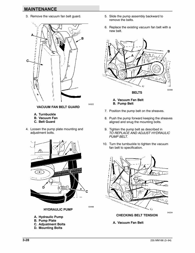
MAINTENANCE
235 MM166 (3--94)3-28
3. Remove the vacuum fan belt guard.
C
AB
04322
VACUUM FAN BELT GUARD
A. TurnbuckleB. Vacuum FanC. Belt Guard
4. Loosen the pump plate mounting andadjustment bolts.
D
B
C
A
03498
HYDRAULIC PUMP
A. Hydraulic PumpB. Pump PlateC. Adjustment BoltsD. Mounting Bolts
5. Slide the pump assembly backward toremove the belts.
6. Replace the existing vacuum fan belt with anew belt.
AB
03499
BELTS
A. Vacuum Fan BeltB. Pump Belt
7. Position the pump belt on the sheaves.
8. Push the pump forward keeping the sheavesaligned and snug the mounting bolts.
9. Tighten the pump belt as described inTO REPLACE AND ADJUST HYDRAULICPUMP BELT.
10. Turn the turnbuckle to tighten the vacuumfan belt to specification.
A
04234
CHECKING BELT TENSION
A. Vacuum Fan Belt

MAINTENANCE
3-29235 MM166 (3--94)
11. Replace the belt guard.
12. Lower the seat support.
MAIN BRUSH BELT
The main brush belt transfers power from theaccessories pump to the main brush. The belt istensioned by a belt idler spring. A stop bolt isused to remove tension from the belt when themain brush is raised.
TO REPLACE MAIN BRUSH BELT
1. Stop the engine and set the machineparking brake.
FOR SAFETY: Before Leaving Or ServicingMachine; Stop On Level Surface, Set ParkingBrake, Turn Off Machine And Remove Key.
2. Raise the main brush.
3. Open the seat support.
4. Remove the vacuum fan belt guard.
5. Remove the left side access door.
6. Hold the idler spring arm back and removethe belt.
A
C
B
03377
MAIN BRUSH BELT
A. Idler Spring ArmB. Main Brush BeltC. Stop Bolt
7. Position the new belt on the belt sheaves.
8. Replace the vacuum fan belt guard.
9. Lower the seat support.
10. Start the machine and lower the main brush.Then raise the brush. The brush should stopturning within seconds of being raised. If thebelt is too tight, the brush will continue toturn. If the belt is too loose, it may jump offthe idler or driven sheave. Turn the belt stopbolt to adjust belt tension.
11. Replace the left side access door.

MAINTENANCE
235 MM166 (3--94)3-30
TAPER LOCK BUSHINGS
Taper lock bushings are used to secure thesheaves on the engine and propelling pumpshafts.
TO REMOVE TAPER LOCK BUSHING
1. Remove all set screws.
2. Insert a set screw into the threaded hole ofthe bushing.
B
CD
A
03506
TAPER LOCK BUSHING
A. Set ScrewB. HubC. BushingD. Threaded Hole
3. Tighten the set screw to loosen bushingfrom shaft.
TO INSTALL TAPER LOCK BUSHING
1. Clean shaft, bore and outside of bushingand hub bore of all oil, lacquer, and dirt.
2. Insert bushing into hub; be aware of sheavealignment. Match hole pattern, not threadedholes. Each hole will be threaded on oneside only.
3. Oil set screws. Thread them into the halfthreaded holes.
4. Alternately tighten the set screws to 175 inlb (20 Nm).
5. Using a block, sleeve, or drift, hammer theend of the bushing. Do not hammer bushingdirectly.
6. Repeat steps 4 and 5 until torque wrenchreading is the same after hammering asbefore.
7. Fill all open holes with grease.
STATIC DRAG CHAIN
The static drag chain prevents the buildup ofstatic electricity in the machine. The chain isattached to the rear skirt retaining strip.
Make sure that the chain is making contact withthe floor at all times.
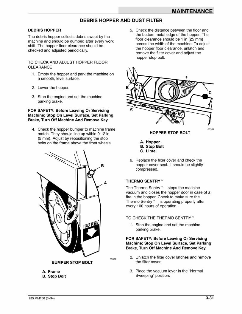
MAINTENANCE
3-31235 MM166 (3--94)
DEBRIS HOPPER AND DUST FILTER
DEBRIS HOPPER
The debris hopper collects debris swept by themachine and should be dumped after every workshift. The hopper floor clearance should bechecked and adjusted periodically.
TO CHECK AND ADJUST HOPPER FLOORCLEARANCE
1. Empty the hopper and park the machine ona smooth, level surface.
2. Lower the hopper.
3. Stop the engine and set the machineparking brake.
FOR SAFETY: Before Leaving Or ServicingMachine; Stop On Level Surface, Set ParkingBrake, Turn Off Machine And Remove Key.
4. Check the hopper bumper to machine framematch. They should line up within 0.12 in(5 mm). Adjust by repositioning the stopbolts on the frame above the front wheels.
B
A
03372
BUMPER STOP BOLT
A. FrameB. Stop Bolt
5. Check the distance between the floor andthe bottom metal edge of the hopper. Thefloor clearance should be 1 in (25 mm)across the width of the machine. To adjustthe hopper floor clearance, unlatch andremove the filter cover and adjust thehopper stop bolt.
B
A
C
03387
HOPPER STOP BOLT
A. HopperB. Stop BoltC. Lintel
6. Replace the filter cover and check thehopper cover seal. It should be slightlycompressed.
THERMO SENTRYt
The Thermo Sentryt stops the machinevacuum and closes the hopper door in case of afire in the hopper. Check to make sure theThermo Sentryt is operating properly afterevery 100 hours of operation.
TO CHECK THE THERMO SENTRYt
1. Stop the engine and set the machineparking brake.
FOR SAFETY: Before Leaving Or ServicingMachine; Stop On Level Surface, Set ParkingBrake, Turn Off Machine And Remove Key.
2. Unlatch the filter cover latches and removethe filter cover.
3. Place the vacuum lever in the “NormalSweeping” position.
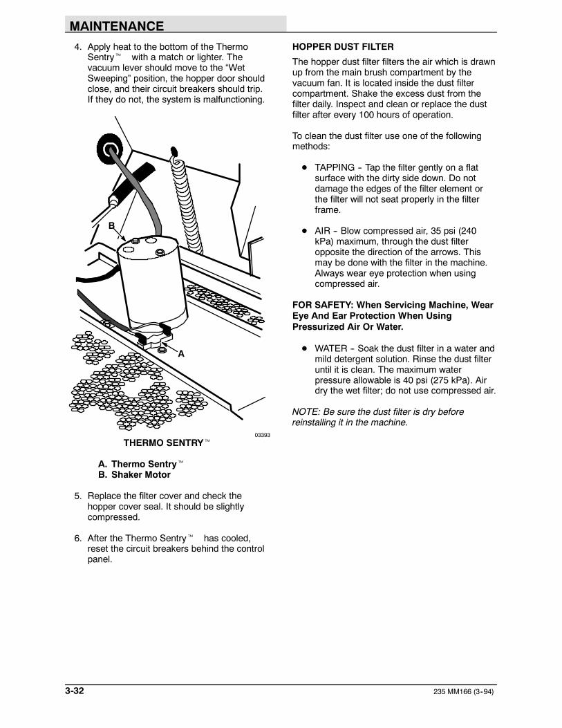
MAINTENANCE
235 MM166 (3--94)3-32
4. Apply heat to the bottom of the ThermoSentryt with a match or lighter. Thevacuum lever should move to the “WetSweeping” position, the hopper door shouldclose, and their circuit breakers should trip.If they do not, the system is malfunctioning.
A
B
03393
THERMO SENTRYt
A. Thermo SentrytB. Shaker Motor
5. Replace the filter cover and check thehopper cover seal. It should be slightlycompressed.
6. After the Thermo Sentryt has cooled,reset the circuit breakers behind the controlpanel.
HOPPER DUST FILTER
The hopper dust filter filters the air which is drawnup from the main brush compartment by thevacuum fan. It is located inside the dust filtercompartment. Shake the excess dust from thefilter daily. Inspect and clean or replace the dustfilter after every 100 hours of operation.
To clean the dust filter use one of the followingmethods:
D TAPPING -- Tap the filter gently on a flatsurface with the dirty side down. Do notdamage the edges of the filter element orthe filter will not seat properly in the filterframe.
D AIR -- Blow compressed air, 35 psi (240kPa) maximum, through the dust filteropposite the direction of the arrows. Thismay be done with the filter in the machine.Always wear eye protection when usingcompressed air.
FOR SAFETY: When Servicing Machine, WearEye And Ear Protection When UsingPressurized Air Or Water.
D WATER -- Soak the dust filter in a water andmild detergent solution. Rinse the dust filteruntil it is clean. The maximum waterpressure allowable is 40 psi (275 kPa). Airdry the wet filter; do not use compressed air.
NOTE: Be sure the dust filter is dry beforereinstalling it in the machine.
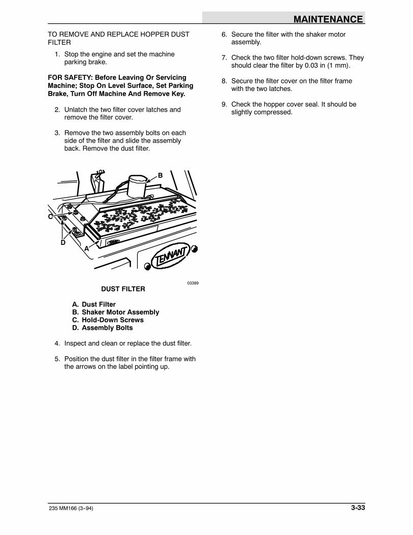
MAINTENANCE
3-33235 MM166 (3--94)
TO REMOVE AND REPLACE HOPPER DUSTFILTER
1. Stop the engine and set the machineparking brake.
FOR SAFETY: Before Leaving Or ServicingMachine; Stop On Level Surface, Set ParkingBrake, Turn Off Machine And Remove Key.
2. Unlatch the two filter cover latches andremove the filter cover.
3. Remove the two assembly bolts on eachside of the filter and slide the assemblyback. Remove the dust filter.
A
B
D
C
03389
DUST FILTER
A. Dust FilterB. Shaker Motor AssemblyC. Hold-Down ScrewsD. Assembly Bolts
4. Inspect and clean or replace the dust filter.
5. Position the dust filter in the filter frame withthe arrows on the label pointing up.
6. Secure the filter with the shaker motorassembly.
7. Check the two filter hold-down screws. Theyshould clear the filter by 0.03 in (1 mm).
8. Secure the filter cover on the filter framewith the two latches.
9. Check the hopper cover seal. It should beslightly compressed.

MAINTENANCE
235 MM166 (3--94)3-34
BRUSHES
MAIN BRUSH
The main brush is tubular and spans the width ofthe machine, sweeping debris into the debrishopper. The brush should be inspected daily forwear or damage. Remove any string or wire foundtangled on the main brush, main brush drive hub,or main brush idler hub.
Rotate the main brush end-for-end after every50 hours of operation for maximum brush life andbest sweeping performance. Check the mainbrush pattern whenever installing a new brush.
The main brush should be replaced when theremaining bristles measure 1.5 in (40 mm) or lessin length.
TO REMOVE MAIN BRUSH
1. Stop engine and set the machine parkingbrake.
FOR SAFETY: Before Leaving Or ServicingMachine; Stop On Level Surface, Set ParkingBrake, Turn Off Machine And Remove Key.
2. Lower the main brush.
3. Remove the right side access door.
4. Remove the brush idler arm retaining boltfrom the arm hub.
B
A
C
D
03390
MAIN BRUSH IDLER ARM
A. Brush Idler ArmB. Arm Retaining BoltC. Main BrushD. Threaded Hole
5. Pull the brush idler arm off the arm hub.
NOTE: If the brush idler arm does not come offeasily, thread the retaining bolt into the threadedhole on the arm. Tighten the bolt until it is tightagainst the backing plate. Push on the brush endof the arm and retighten the bolt. Repeat until thearm is loose.
6. Grasp the main brush, pull it off the brushdrive plug, and out of the main brushcompartment.
TO INSTALL MAIN BRUSH
1. Push the main brush lever into the “UP”position.
2. Slide the main brush into the main brushcompartment.
3. Align the main brush drive slots with thedrive keys on the main brush drive plug.
4. Slide the main brush onto the drive plug.Make sure the drive slots and keys mate.
5. Align the main brush idler plug slots with themain brush keys. Slide the main brush idlerplug into the main brush tube.
6. Slide the brush idler arm onto the arm hub.
7. Thread the brush idler arm retaining boltthrough the idler arm and into the arm hub.
8. Tighten the brush idler arm retaining bolt.
9. Replace the right side access door.
TO CHECK AND ADJUST MAIN BRUSHPATTERN
1. Apply chalk, or some other material that willnot blow away easily, to a smooth, levelfloor.
2. With the side brush and main brush raised,position the main brush over the chalkedarea.
3. While keeping a foot on the brakes to keepthe machine from moving, lower the mainbrush to the floor for 15 to 20 seconds; raisethe main brush and drive the machine off thetest area.

MAINTENANCE
3-35235 MM166 (3--94)
NOTE: If no chalk or other material is available,allow the brushes to spin on the floor for twominutes.
4. Observe the brush pattern made. Thepattern should be of equal width across thelength of the pattern.
A
B
00582
NORMAL MAIN BRUSH PATTERN
A. Main Brush PatternB. 2 to 2.5 in (51 to 54 mm) for
machines serial number 002594 andabove
For machines serial number 002594 andabove, and machines with the Brush LimiterKit installed, the brush pattern width shouldbe 2 to 2.5 in (51 to 54 mm). The brushpattern width can be adjusted by looseningand moving the brush limiter nut.
A
B
03487
BRUSH LIMITER NUT (For machines serialnumber 002594 and above)
A. Brush Limiter NutB. Main Brush Lever Slot
To decrease the width of the brush pattern,move the limiter nut forward and tighten thenut. To increase the brush pattern width,move the limiter nut back and tighten thenut.
If the main brush pattern is tapered, wideron one side by 0.50 in (15 mm) or more thanthe other side, perform the following levelingprocedure:
00601
TAPERED MAIN BRUSH PATTERN
A. Park the machine on a level surface.
B. Stop the engine and set the machineparking brake.
FOR SAFETY: Before Leaving Or ServicingMachine; Stop On Level Surface, Set ParkingBrake, Turn Off Machine And Remove Key.
C. Lower the main brush.
D. Remove the right side access door.
E. Remove the main brush.
F. Reinstall the idler arm.
G. Loosen the cross shaft bearing flangebolts.
A
C
B
03550
CROSS SHAFT BEARING FLANGE
A. FlangeB. BoltsC. Cross Shaft

MAINTENANCE
235 MM166 (3--94)3-36
H. Position the idler plug so it is the samedistance from the floor as the drive plugand tighten the bolts.
I. Reinstall the main brush.
J. Recheck the main brush pattern.
K. Replace the right side access door.
SIDE BRUSH
The side brush sweeps debris from curbs orgutters into the path of the main brush. The sidebrush should be inspected daily for wear ordamage. Remove any string or wire found tangledon the side brush or side brush drive hub.
The side brush pattern should be checkedperiodically. One-third of the side brush bristlesshould contact the floor when the brush is inmotion. The side brush pattern adjustment ismade by turning the side brush adjustment knobon the front bumper.
The side brush should be replaced when theremaining brush bristle measures 2.5 in (65 mm)in length.
TO REMOVE SIDE BRUSH
1. Raise the hopper.
2. Engage the hopper support bar.
WARNING: Falling Hopper. EngageHopper Support Bar. Read Manual.
3. Stop the engine and set the machineparking brake.
FOR SAFETY: Before Leaving Or ServicingMachine; Stop On Level Surface, Set ParkingBrake, Turn Off Machine And Remove Key.
4. Raise the side brush.
5. Remove the four side brush retaining boltsfrom the bottom of the side brush.
A
B
03392
SIDE BRUSH
A. Side BrushB. Retaining Bolts
6. Slide the side brush off the side brush hub.
TO INSTALL SIDE BRUSH
1. Position the side brush on the side brushdrive hub.
2. Secure the side brush to the hub with thefour bolts removed earlier.
3. Check the side brush pattern. Adjust thepattern with the side brush adjustment knob.
A
03376
SIDE BRUSH PATTERN
A. Contact Area

MAINTENANCE
3-37235 MM166 (3--94)
SKIRTS AND SEALS
BRUSH SKIRTS
Brush skirts control main brush dusting. They arelocated on each of the brush access doors. Theskirts should be inspected for wear or damagedaily. They should clear the floor by 0 to 0.12 in (0to 5 mm) at all times.
TO REPLACE AND ADJUST BRUSH SKIRTS
1. Park the machine on a smooth, level floor.
2. Stop the engine and set the machineparking brake.
FOR SAFETY: Before Leaving Or ServicingMachine; Stop On Level Surface, Set ParkingBrake, Turn Off Machine And Remove Key.
3. Remove the side access doors.
4. Replace or loosen the skirt and retainingstrip bolts. Adjust the skirt height andretighten the retaining strip bolts.
A
B03388
RIGHT SIDE BRUSH SKIRT
A. Retaining StripB. Brush Skirt
5. Replace the doors.
6. Check the skirt clearance.
REAR SKIRTS
The rear skirts seal the brush compartment. Theyare located on the bottom rear of the brushcompartment. The seals should be inspected forwear or damage daily.
TO REPLACE AND ADJUST REAR SKIRTS
1. Park the machine on a smooth, levelsurface.
2. Stop the engine and set the machineparking brake.
FOR SAFETY: Before Leaving Or ServicingMachine; Stop On Level Surface, Set ParkingBrake, Turn Off Machine And Remove Key.
3. Remove the side access doors.
4. Remove the rear skirt retaining strips andthe rear skirts.
AB
C
03390
REAR SKIRTS
A. Brush SkirtB. Vertical Rear SkirtC. Retaining Strip
5. Loosely install new skirts with the existingretaining strips.
6. Slide the vertical rear skirt up or down so itis 0 to 0.12 in (0 to 5 mm) above the floor.
7. Retighten the retaining strip bolts.
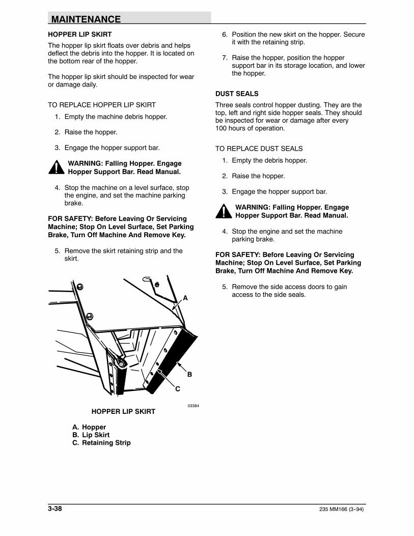
MAINTENANCE
235 MM166 (3--94)3-38
HOPPER LIP SKIRT
The hopper lip skirt floats over debris and helpsdeflect the debris into the hopper. It is located onthe bottom rear of the hopper.
The hopper lip skirt should be inspected for wearor damage daily.
TO REPLACE HOPPER LIP SKIRT
1. Empty the machine debris hopper.
2. Raise the hopper.
3. Engage the hopper support bar.
WARNING: Falling Hopper. EngageHopper Support Bar. Read Manual.
4. Stop the machine on a level surface, stopthe engine, and set the machine parkingbrake.
FOR SAFETY: Before Leaving Or ServicingMachine; Stop On Level Surface, Set ParkingBrake, Turn Off Machine And Remove Key.
5. Remove the skirt retaining strip and theskirt.
A
B
C
03384
HOPPER LIP SKIRT
A. HopperB. Lip SkirtC. Retaining Strip
6. Position the new skirt on the hopper. Secureit with the retaining strip.
7. Raise the hopper, position the hoppersupport bar in its storage location, and lowerthe hopper.
DUST SEALS
Three seals control hopper dusting. They are thetop, left and right side hopper seals. They shouldbe inspected for wear or damage after every100 hours of operation.
TO REPLACE DUST SEALS
1. Empty the debris hopper.
2. Raise the hopper.
3. Engage the hopper support bar.
WARNING: Falling Hopper. EngageHopper Support Bar. Read Manual.
4. Stop the engine and set the machineparking brake.
FOR SAFETY: Before Leaving Or ServicingMachine; Stop On Level Surface, Set ParkingBrake, Turn Off Machine And Remove Key.
5. Remove the side access doors to gainaccess to the side seals.

MAINTENANCE
3-39235 MM166 (3--94)
6. Remove the retaining strip of the seal to bereplaced.
B
A
03369
HOPPER SEALS
A. Top Hopper SealB. Side Hopper Seal
7. Remove the existing seal or skirt.
8. Mount the new seal or skirt to the machinewith the retaining strip removed earlier.
9. Replace the side access doors if removed.
10. Raise the hopper, place the hopper supportbar in its storage position, and lower thehopper.
HOPPER DUMP DOOR SEAL
The hopper dump door seal allows the hopper tobe high dumped without scattering debris. Checkthe seal for damage after every 100 hours ofoperation.
TO REPLACE HOPPER DUMP DOOR SEAL
1. Empty the debris hopper.
2. Raise the hopper.
3. Engage the hopper support bar.
WARNING: Falling Hopper. EngageHopperSupport Bar. Read Manual.
4. Stop the engine and set the machineparking brake.
FOR SAFETY: Before Leaving Or ServicingMachine; Stop On Level Surface, Set ParkingBrake, Turn Off Machine And Remove Key.
5. Open the dump door.
6. Remove the seal retaining strip.
A
B03384
HOPPER DUMP DOOR SEAL
A. HopperB. Dump Door Seal
7. Remove the seal.
8. Mount the new seal to the door with thesponge core and retaining strip removedearlier.
9. Raise the hopper, position the hoppersupport bar in its storage position, and lowerthe hopper.

MAINTENANCE
235 MM166 (3--94)3-40
VACUUM FAN SEAL
The vacuum fan seal seals the vacuum fan to thefilter cover. Check the seal for damage after every100 hours of operation.
A
03387
VACUUM FAN SEAL
A. Vacuum Fan Seal
FILTER COVER SEAL
The filter cover seal seals the filter box to the filtercover. Check the seal for damage after every100 hours of operation.
A B
03375
FILTER COVER SEAL
A. Filter CoverB. Seal

MAINTENANCE
3-41235 MM166 (8--95)
BRAKES AND TIRES
BRAKES
The foot brake and the parking brake operate thelinkage which controls the brakes on the frontwheels.
The foot brake needs no regular adjustment. Theparking brake should be adjusted after every200 hours of operation or whenever it becomesvery easy to set.
To adjust the parking brake, turn the knurled knobon the end of the parking brake clockwise. If theknob adjustment is inadequate, remove the clevispin from each brake assembly, turn the clevisends an equal amount, reconnect the clevis pins,and readjust the parking brake.
BA
03369
BRAKE ASSEMBLY
A. ClevisB. Brake Rod
TIRES
The front machine tires are solid. The rear tire ispneumatic. Proper air pressure is 90 psi(620 kPa). They should be inspected for wearafter every 100 hours of operation.
REAR WHEEL
Torque the rear wheel nuts in a star pattern to122 to 150 Nm (90 to 110 ft lb) after the first50-hours of operation, and every 800 hours thereafter.
MAINTENANCE
235 MM166 (3--94)3-42

APPENDIX
4-1235 MM166 (5--91)
SECTION 4CONTENTS
PageHARDWARE INFORMATION 4-3. . . . . . . . . . . .
STANDARD BOLT TORQUE CHART 4-3. .METRIC BOLT TORQUE CHART 4-3. . . . .BOLT IDENTIFICATION 4-3. . . . . . . . . . . . . .THREAD SEALANT AND LOCKING
COMPOUNDS 4-3. . . . . . . . . . . . . . . . . . .HYDRAULIC FITTING INFORMATION 4-4. . . .
HYDRAULIC TAPERED PIPE FITTING(NPT) TORQUE CHART 4-4. . . . . . . . . .
HYDRAULIC TAPERED SEAT FITTING(JIC) TORQUE CHART 4-4. . . . . . . . . . .
HYDRAULIC O--RING FITTINGTORQUE CHART 4-4. . . . . . . . . . . . . . . .

APPENDIX
235 MM166 (5--91)4-2

APPENDIX
4-3235 MM166 (5--91)
HARDWARE INFORMATION
The following charts state standard platedhardware tightening ranges for normal assemblyapplications. Decrease the specified torque by20% when using a thread lubricant. Do notsubstitute lower grade hardware for higher gradehardware. If higher grade hardware than specifiedis substituted, tighten only to the specifiedhardware torque value to avoid damaging thethreads of the part being threaded into, as whenthreading into speed nuts or weldments.
STANDARD BOLT TORQUE CHARTThread SAE Grade 5 SAE Grade 8Size Torque ft lb (Nm) Torque ft lb (Nm)
0.25 in 7--10 (9--14) 10--13 (14--38)0.31 in 15--20 (20--27) 20--26 (27--35)0.38 in 27--35 (37--47) 36--47 (49--64)0.44 in 43--56 (58--76) 53--76 (72--103)0.50 in 65--85 (88--115) 89--116 (121--157)0.62 in 130--170 (176--231) 117--265 (159--359)0.75 in 215--280 (291--380) 313--407 (424--552)1.00 in 500--650 (678--881) 757--984 (1026--1334)
NOTE: Decrease torque by 20% when using athread lubricant.
METRIC BOLT TORQUE CHARTThread Class 8.8 Class 10.9Size Torque ft lb (Nm) Torque ft lb (Nm)
M4 2 (3) 3 (4)M5 4 (5) 6 (8)M6 7 (9) 10 (14)M8 18 (24) 25 (34)M10 32 (43) 47 (64)M12 58 (79) 83 (112)M14 94 (127) 133 (180)M16 144 (195) 196 (265)M20 260 (352) 336 (455)M24 470 (637) 664 (900)
NOTE: Decrease torque by 20% when using athread lubricant.
Exceptions to the above chart:
Main brush drive plug nut -- 30 ft lb (40 Nm)then tighten to next slot.
Brake unit to hub sockethead screw --9 to 12 ft lb (12 to 16 Nm) with Locktite 242blue.
Front wheel nut -- 10 to 12 ft lb (14 to16 Nm) while turning wheel, tighten to spec,then backoff, retighten by hand till snug,then turn to next slot.
Rear hub to shaft nut -- 175 ft lb (240 Nm)then to next slot.
Damper solenoid nut -- 20 to 23 in lb(2.5 to 3 Nm).
BOLT IDENTIFICATION
Identification SpecificationGrade Marking and Grade
SAE--Grade 5
SAE--Grade 8
ISO--Grade 8.8
ISO--Grade 10.901395
THREAD SEALANT AND LOCKINGCOMPOUNDS
Thread sealants and locking compounds may beused on this machine. They include the following:
Locktite 515 sealant -- gasket formingmaterial. TENNANT Part No. 75567,15 oz(440 ml) cartridge.
Locktite 242 blue -- medium strength threadlocking compound. TENNANT Part No.32676, 0.5 ml tube.
Locktite 271 red -- high strength threadlocking compound. TENNANT Part No.19857, 0.5 ml tube.

APPENDIX
235 MM166 (5--91)4-4
HYDRAULIC FITTING INFORMATION
HYDRAULIC TAPERED PIPE FITTING (NPT)TORQUE CHART
NOTE: Ratings listed are when using teflonthread seal.
Minimum MaximumSize Torque Torque
1/4 NPT 10 ft lb (14 Nm) 30 ft lb (41 Nm)1/2 NPT 25 ft lb (34 Nm) 50 ft lb (68 Nm)3/4 NPT 50 ft lb (68 Nm) 100 ft lb (136 Nm)
HYDRAULIC TAPERED SEAT FITTING (JIC)TORQUE CHARTTube Thread MaximumO.D. (in) Size Torque
0.25 0.44--20 9 ft lb (12 Nm)0.38 0.56--18 20 ft lb (27 Nm)0.50 0.75--16 30 ft lb (41 Nm)0.62 0.88--14 40 ft lb (54 Nm)0.75 1.12--12 70 ft lb (95 Nm)1.0 1.31--12 90 ft lb (122 Nm)
HYDRAULIC O--RING FITTING TORQUECHARTTube Thread Minimum MaximumO.D.(in) Size Torque Torque
0.25 0.44--20 6 ft lb (8 Nm) 9 ft lb (12 Nm)0.38 0.56--18 13 ft lb (18 Nm) 20 ft lb (27 Nm)
*10 ft lb (14 Nm) 12 ft lb (16 Nm)0.50 0.75--16 20 ft lb (27 Nm) 30 ft lb (41 Nm)
*21 ft lb (28 Nm) 24 ft lb (33 Nm)0.62 0.88--14 25 ft lb (34 Nm) 40 ft lb (54 Nm)0.75 1.12--12 45 ft lb (61 Nm) 70 ft lb (95 Nm)1.0 1.31--12 60 ft lb (81 Nm) 90 ft lb (122 Nm)
NOTE: Do not use sealant on o--ring threads.
*Aluminum bodied components

STANDARD MODEL PARTS
5-1235 MM166 (3-94)
SECTION 5CONTENTS
PageORDERING REPAIR PARTS 5-3. . . . . . . . . . . . . . .Fig. 1 -- Recommended General
Maintenance Items 5-4. . . . . . . . . . . . .Fig. 2 -- Replacement Brushes 5-5. . . . . . . . . . . . . .Fig. 3 -- Main Frame Group 5-6. . . . . . . . . . . . . . . .Fig. 4 -- Seat and Shrouds Group 5-8. . . . . . . . . . .Fig. 5 -- Front Wheel and Brake Group 5-10. . . . . . .Fig. 6 -- Hopper Lift Arms Group 5-12. . . . . . . . . . . .Fig. 7 -- Hopper Middle and Cover Group 5-14. . . . .Fig. 8 -- Hopper Bottom Group 5-16. . . . . . . . . . . . . .Fig. 9 -- Hopper Headlights and
Access Door Group 5-18. . . . . . . . . . . .Fig. 10 -- Hopper Filter and Shaker
Motor Group 5-19. . . . . . . . . . . . . . . . . .Fig. 11 -- Hopper Dump Door and
Actuator Group 5-20. . . . . . . . . . . . . . . .Fig. 12 -- Vacuum Fan Control Group 5-22. . . . . . . .Fig. 13 -- Vacuum Fan Assembly 5-24. . . . . . . . . . . .Fig. 14 -- Main Brush Drive Group 5-26. . . . . . . . . . .Fig. 15 -- Main Brush Idler Group 5-28. . . . . . . . . . . .Fig. 16 -- Side Brush Group 5-30. . . . . . . . . . . . . . . . .Fig. 17 -- Hydraulic Lift Cylinder and
Filter Group 5-32. . . . . . . . . . . . . . . . . . .Fig. 18 -- Pump Group 5-34. . . . . . . . . . . . . . . . . . . . .Fig. 19 -- Control Valve and Throttle Group 5-36. . . .Fig. 20 -- Hydraulic Reservoir Group 5-38. . . . . . . . .Fig. 21 -- Rear Drive Wheel Group 5-39. . . . . . . . . . .Fig. 22 -- Hydraulic Hoses Group 5-40. . . . . . . . . . . .Fig. 23 -- Steering Wheel Group 5-42. . . . . . . . . . . . .Fig. 24 -- Directional Pedal Group 5-44. . . . . . . . . . . .Fig. 25 -- Speed Limiter Group 5-45. . . . . . . . . . . . . .Fig. 26 -- Engine Group 5-46. . . . . . . . . . . . . . . . . . . .Fig. 27 -- Fuel Tank and Line Group 5-48. . . . . . . . . .Fig. 28 -- Battery and Air Intake Group 5-50. . . . . . .Fig. 29 -- Control Panel Group 5-52. . . . . . . . . . . . . . .Fig. 30 -- Wire Harness Group 5-54. . . . . . . . . . . . . . .Fig. 31 -- Labels Group 5-56. . . . . . . . . . . . . . . . . . . . .
NOTE: SECTION 5, STANDARD MODEL PARTS,lists repair parts for a standard model, gasolinepowered machine. This section also contains partscommon to all models of the machine.

STANDARD MODEL PARTS
235 MM166 (5--91)5-2

STANDARD MODEL PARTS
5-3235 MM166 (5--91)
ORDERING REPAIR PARTSThe components used in this machine have beencarefully selected for performance and safety. Useonly TENNANT specified or equivalent parts.
To receive prompt service in filling of your partsorders, please direct all orders for parts withTENNANT part numbers to the TENNANT, and allorders for parts with vendor part numbers to the localsupplier of the respective vendor.
When ordering parts, please furnish all of thefollowing information:
1. Machine model number - shown on the machinedata plate.
SER.NO.
GVW. LBS. KG.
TENNANT COMPANYMINNEAPOLIS, MINN USA
2. Machine serial number - shown on the machinedata plate.
3. Power source - gasoline, LPG, diesel, electric.
4. Company name.
5. Shipping address.
6. Billing address.
7. Name, first and last - of person ordering parts.
8. Telephone number.
9. Purchase order number.
10. Part number, description, and quantity - of eachitem on the order.
11. Customer ID Number.
Do not order parts by key number or the figurenumber of the illustrated parts. Indented itemsindicate parts of assemblies. Standard hardware isfurnished only when part of a purchased assembly.Please get hardware from a local hardware supplier.
If the old part cannot be identified, send it to us withthe quantity needed specified on the order.
Any claim for loss or damage to a shipment in transitshould be filed promptly against the transportationcompany making the delivery. Shipments will becomplete unless the packing list or order ack-nowledgement indicate items back ordered.
If parts received are suspected to be incorrect ordefective, please write, wire, or phone the TENNANTrepresentative from whom you ordered the part. Theywill give authorization for return and/or handlereplacement shipments when required.
SERIAL NUMBER INFORMATION EXPLANATION
Serial number listings are shown to indicate on whichmachines each part can be used. These listings areexplained by the following examples:
(000000-- ) The part can be used on all machines.
(003342-- ) The part can be used on all machinesbeginning with the serial number listed.
(000000--004320) The part can be used on allmachines up to and including serial number listed.
(004321--005678) The part can be used on allmachines between and including the serial numberslisted.
Where xxxxxx’s are listed in place of a serial number,it indicates a change was made but the exact serialnumber had not been established when the catalogwent to press.
SI UNITS OF MEASURE(INTERNATIONAL SYSTEM)
Metric equivalents have been included, whereapplicable, throughout this parts catalog.
FASTENER STRENGTH IDENTIFICATION
Fasteners required to have high--strength qualitiesequivalent to SAE Grade 8 are identified throughoutthis catalog by the description GR 8. Unless identifiedby this description, all standard fasteners are SAEGrade 5.
(Specifications and design subject to change withoutnotice.)

STANDARD MODEL PARTS
235 MM166 (3-94)5-4
03597
Fig. 1 -- Recommended General Maintenance Items
TENNANT MachineKey Part No. Serial Number Description Qty.
87961 (000000-- ) Maintenance Kit, 400 Hour, Gasoline 187871 (000000-- ) Spark Plug Set 187915 (000000-- ) Spark Plug 287898 (000000-- ) Gasket Kit, Cover 187899 (000000-- ) Gasket, Cover 3
87920 (000000-- ) Breather, Filter 187873 (000000-- ) Pre--Cleaner, Air Cleaner 187872 (000000-- ) Element, Air Cleaner 187874 (000000-- ) Filter, Engine Oil 862050 (000000-- ) Filter, Fuel 1
82526 (000000-- ) Hose, Fuel Line 165870--5 (000000-- ) Hydraulic Fluid, (5/20), 5 gal (18.9 l) 167718--2 (000000-- ) Element, Hydraulic Filter 187962 (000000-- ) Maintenance Kit, 400 Hour, LPG 187871 (000000-- ) Spark Plug Set 1
87915 (000000-- ) Spark Plug 287898 (000000-- ) Gasket Kit, Cover 187899 (000000-- ) Gasket,Cover 187920 (000000-- ) Breather, Filter 187873 (000000-- ) Pre--Cleaner, Air Cleaner 1
87872 (000000-- ) Element, Air Cleaner 187874 (000000-- ) Filter, Engine Oil 865870--5 (000000-- ) Hydraulic Fluid, (5/20), 5 gal (18.9 l) 167718--2 (000000-- ) Element, Hydraulic Filter 1SK1444 (000000-- ) Repair Kit, Filter Fuel Lock 1
87963 (000000-- ) Maintenance Kit, Hopper 187405 (000000-- ) Seal, Hopper Halves 187217 (000000-- ) Seal, Hopper Cover 187338 (000000-- ) Seal, Access Door 168198 (000000-- ) Adhesive, 1 oz (30 ml) 1
87061 (000000-- ) Lip, Hopper Rear 187060 (000000-- ) Retainer, Hopper Lip 187412 (000000-- ) Seal, Dump Door 287413 (000000-- ) Spacer, Seal 287689 (000000-- ) Cord, Sponge 1
87688 (000000-- ) Wrap, Dump Door Seal 187687 (000000-- ) Retainer, Hopper Seal 187164 (000000-- ) Seal, Dump Door Top 187165 (000000-- ) Retainer, Seal 187167 (000000-- ) Retainer, Door Seal 1
34323 (000000-- ) Screw, Hex, Nylon Lock 587964 (000000-- ) Maintenance Kit, Rear Skirt 187197 (000000-- ) Flap, Recirculation 187199 (000000-- ) Seal, Rear Brush Wrap 187586 (000000-- ) Angle, Recirculation Flap 1
87206 (000000-- ) Retainer, Rear Seal 134292 (000000-- ) Screw, Hex, Nylon Lock 787965 (000000-- ) Maintenance Kit, Seals 187465 (000000-- ) Seal, Brush Lift Handle 187464 (000000-- ) Retainer, Brush Lift Seal 1
87181 (000000-- ) Seal, Hopper Top 187180 (000000-- ) Retainer, Hopper Top Seal 187211 (000000-- ) Skirt, Lower, L.H. 1

STANDARD MODEL PARTS
5-5235 MM166 (3-94)
Fig. 1 -- Recommended General Maintenance Items
TENNANT MachineKey Part No. Serial Number Description Qty.
87555 (000000-- ) Retainer, Lower Skirt 187975 (000000-- ) Retainer, Skirt, L.H. 187184 (000000-- ) Seal, Hopper, L.H. 187182 (000000-- ) Retainer, Felt Seal 134292 (000000-- ) Screw, Hex, Nylon Lock 4
87175 (000000-- ) Skirt, Lower, R.H. 187176 (000000-- ) Retainer, Lower Seal 187183 (000000-- ) Seal, Hopper, R.H. 187182 (000000-- ) Retainer, Felt Seal 187353 (000000-- ) Seal, Foam Rubber 2
87354 (000000-- ) Seal, Foam Rubber 287731 (000000-- ) Seal, Foam Rubber 168198 (000000-- ) Adhesive, 1 oz (30 ml) 147069 (000000-- ) Sleeve, Vacuum Fan Tube 1
1
2
03561
Fig. 2 -- Replacement Brushes
TENNANT MachineKey Part No. Serial Number Description Qty.
1 87419 (000000-- ) Side Brush, Polypropylene 11 87420 (000000-- ) Side Brush, Nylon 12 87333 (000000-- ) Main Brush, 24 Single Row, Polyester 12 87097 (000000-- ) Main Brush, 8 Double Row, Proex and Wire 12 87334 (000000-- ) Main Brush, 8 Double Row, Polyester 1
2 87099 (000000-- ) Main Brush, 8 Double Row, Polypropylene 1

STANDARD MODEL PARTS
235 MM166 (3-94)5-6
2
3
4
5
6
7
89
10
1
11
12 13
14
15
16 17
18
19
20
21
22 23
2425
26
27
28
18
4
5
4
Fig. 3 -- Main Frame Group

STANDARD MODEL PARTS
5-7235 MM166 (5--91)
03462
Fig. 3 -- Main Frame Group
TENNANT MachineKey Part No. Serial Number Description Qty.
1 87500 (000000-- ) Frame, Main 12 87181 (000000-- ) Seal, Hopper Top 13 87180 (000000-- ) Retainer, Seal 14 34292 (000000-- ) Screw, Nylon Hex 115 87182 (000000-- ) Retainer, Felt Seal 2
6 87184 (000000-- ) Seal, Hopper, L.H. 17 87183 (000000-- ) Seal, Hopper, R.H. 18 87190 (000000-- ) Door Assembly, Brush, R.H. 19 87353 (000000-- ) Seal, Foam Rubber 110 87354 (000000-- ) Seal, Foam Rubber 1
11 87731 (000000-- ) Seal, Foam Rubber 112 87176 (000000-- ) Retainer, Lower Seal 113 87175 (000000-- ) Skirt, Lower, R.H. 114 87464 (000000-- ) Retainer, Seal 115 87465 (000000-- ) Seal, Brush Lift Handle 1
16 87211 (000000-- ) Skirt, Lower, L.H. 117 87555 (000000-- ) Retainer, Lower Skirt 118 01760 (000000-- ) Nut, Nylon Lock 419 87189 (000000-- ) Door Assembly, Brush, L.H. 120 87353 (000000-- ) Seal, Foam Rubber 1
21 87354 (000000-- ) Seal, Foam Rubber 122 87197 (000000-- ) Flap, Recirculation 123 87586 (000000-- ) Angle, Recirculation Flap 124 87199 (000000-- ) Seal, Rear 125 87206 (000000-- ) Retainer, Rear Seal 1
26 47277 (000000-- ) Chain, Link 127 87975 (000000-- ) Retainer, Skirt, L.H. 128 87970 (000000-- ) Seal, Foam 1

STANDARD MODEL PARTS
235 MM166 (3-94)5-8
MainFrame
11
7
1
3
8
9
6
42
14
1312
10
5
1516
Fig. 4 -- Seat and Shrouds Group

STANDARD MODEL PARTS
5-9235 MM166 (3-94)
03478
Fig. 4 -- Seat and Shrouds Group
TENNANT MachineKey Part No. Serial Number Description Qty.
1 82342 (000000-- ) Seat Assembly 12 68275 (000000--002611 ) Pouch, Operator’s Manual, 13.6 in (345 mm) 12 48790 (002612-- ) Pouch, Operator’s Manual, 7.5 in (190 mm) 13 87612 (000000-- ) Latch, Shroud 14 62170--2 (000000-- ) Molding, Rigid 1
5 43454 (000000-- ) Washer, Nylon 26 87581 (000000-- ) Spring, Torsion 17 87481 (000000-- ) Shroud 18 87407 (000000-- ) Insulation, Foam 19 87408 (000000-- ) Insulation, Foam 1
10 29233 (000000-- ) Bumper, Rubber 311 36192 (000000-- ) Lanyard Assembly 112 87705 (000000-- ) Tie Down, Cable 513 49266 (000000-- ) Tie, Cable 614 46236 (000000-- ) Clamp, Cable 2
15 87346 (000000-- ) Taillight Assembly 287948 (000000-- ) Bulb 187949 (000000-- ) Socket Assembly 1
16 57772 (000000-- ) Plate, Cover 2

STANDARD MODEL PARTS
235 MM166 (5--91)5-10
MainFrame
20
15
12
75
19
17
16
18
1413
1236
2122
22
10 9
8
4
11
24
Fig. 5 -- Front Wheel and Brake Group

STANDARD MODEL PARTS
5-11235 MM166 (5--91)
03477
Fig. 5 -- Front Wheel and Brake Group
TENNANT MachineKey Part No. Serial Number Description Qty.
1 86922 (000000-- ) Cap, Hub 22 87053 (000000-- ) Nut, Slotted 23 28862 (000000-- ) Washer, Thrust 24 87253 (000000-- ) Wheel Assembly 25 87195 (000000-- ) Tire, Solid 1
6 46390 (000000-- ) Bearing, Ball 27 39296 (000000-- ) Screw, Socket 128 87050 (000000-- ) Shaft, Front Wheel 29 87046 (000000-- ) Hub, Front Wheel 210 26315 (000000-- ) Pin, Roll 2
11 87270 (000000-- ) Rod, Brake 212 13352 (000000-- ) Spring, Tension 213 14595--1 (000000-- ) Clevis, Adjustable 214 14605 (000000-- ) Pin, Clevis 215 87134 (000000-- ) Shaft, Brake 1
16 51109 (000000-- ) Pad 117 51562 (000000-- ) Sleeve 218 51545 (000000-- ) Lever, Brake 119 87248 (000000-- ) Arm, Extension 220 10120 (000000-- ) Pin, Clevis 1
21 87142 (000000-- ) Brake Assembly 222 87868 (000000-- ) Shoes, Brake (Set for 1 Wheel) 123 87869 (000000-- ) Springs, Brake (Set for 1 Wheel) 124 87966 (000000-- ) Clip 1

STANDARD MODEL PARTS
235 MM166 (5--91)5-12
7
4
65
15
3
2
9
10
12
12
14
MainFrame
11
11
8
1
13
13
Fig. 6 -- Hopper Lift Arms Group

STANDARD MODEL PARTS
5-13235 MM166 (5--91)
03470
Fig. 6 -- Hopper Lift Arms Group
TENNANT MachineKey Part No. Serial Number Description Qty.
1 87854 (000000-- ) Arm and Decal Assembly, Lift 12 87229 (000000-- ) Pin, Pivot 13 87228 (000000-- ) Arm, Prop 14 87045 (000000-- ) Bearing, Self--Aligning 25 87433 (000000-- ) Spacer 2
6 87148 (000000-- ) Spacer 27 87146 (000000-- ) Pin, Pivot 28 87147 (000000-- ) Ring, Retaining 49 10632--13 (000000-- ) Grommet 110 87244 (000000-- ) Clip, Spring 1
11 87216 (000000-- ) Bearing, Flange 212 41187 (000000-- ) Washer, Belleville 213 52238 (000000-- ) Spring, Tension 214 86646 (000000-- ) Screw, Hex 215 87149 (000000-- ) Bearing, Journal 1

STANDARD MODEL PARTS
235 MM166 (5--91)5-14
HopperBottom
FrontPlate
12
13
2
2
1
3
5
4
5
6
98
7
10
11
HopperBack
1415
Fig. 7 -- Hopper Middle and Cover Group

STANDARD MODEL PARTS
5-15235 MM166 (5--91)
03268
Fig. 7 -- Hopper Middle and Cover Group
TENNANT MachineKey Part No. Serial Number Description Qty.
1 87203 (000000-- ) Cover, Hopper 12 87579 (000000-- ) Latch, Tension 23 87217 (000000-- ) Seal, Hopper Cover 14 87202 (000000-- ) Hopper, Middle 15 87056 (000000-- ) Strike, Hopper Cover 2
6 87405 (000000-- ) Seal 17 87165 (000000-- ) Retainer, Seal 18 87167 (000000-- ) Retainer, Door Seal 19 87164 (000000-- ) Seal, Dump Door 110 87390 (000000-- ) Baffle, Debris, L.H. 1
11 87166 (000000-- ) Baffle, Debris, R.H. 112 87113 (000000-- ) Plate, Pivot, L.H. 113 87114 (000000-- ) Plate, Pivot, R.H. 114 34323 (000000-- ) Screw, Nylon Hex 515 87958 (000000-- ) Washer, Nylon 6

STANDARD MODEL PARTS
235 MM166 (5--91)5-16
6
2
3
2
1
HopperMiddle
9
8
7
4
5
4
11
10
10
12
Fig. 8 -- Hopper Bottom Group

STANDARD MODEL PARTS
5-17235 MM166 (12--94)
03267
Fig. 8 -- Hopper Bottom Group
TENNANT MachineKey Part No. Serial Number Description Qty.
1 87059 (000000-- ) Plate, Hopper Bottom 12 87103 (000000-- ) Angle, Support 23 87201 (000000-- ) Hopper, Bottom 14 87406 (000000-- ) Angle, Bottom Support 25 87208 (000000-- ) Plate, Front 1
6 87461 (000000-- ) Angle, Stiffener 17 87061 (000000-- ) Lip, Rear 18 87060 (000000-- ) Retainer, Lip 19 87117 (000000-- ) Bumper, Front 110 87958 (000000-- ) Washer, Nylon 4
11 87969 (000000-- ) Deflector, Hopper, R.H. 112 87979 (000000-- ) Deflector, Hopper, L.H. 1

STANDARD MODEL PARTS
235 MM166 (5--91)5-18
6
8
HopperMiddle
2
1
5
3
9
74
4
03467
Fig. 9 -- Hopper Headlights and Access Door Group
TENNANT MachineKey Part No. Serial Number Description Qty.
1 87460 (000000-- ) Mount, Headlight 22 87430 (000000-- ) Lamp 23 87739 (000000-- ) Guard, Headlight 24 87337 (000000-- ) Latch, Door 25 87621 (000000-- ) Door, Access 1
6 87338 (000000-- ) Seal, Access Door 17 26395--2 (000000-- ) Clamp, Cable 28 10632--11 (000000-- ) Grommet, Rubber 19 10632--15 (000000-- ) Grommet, Rubber 1
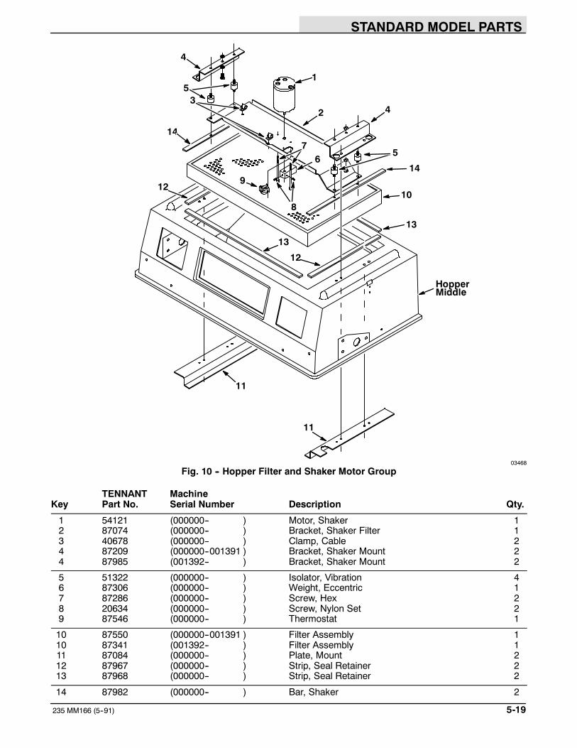
STANDARD MODEL PARTS
5-19235 MM166 (5--91)
1
2
10
4
4
11
11
5
8
5
9
67
HopperMiddle
3
13
13
12
14
14
12
03468
Fig. 10 -- Hopper Filter and Shaker Motor Group
TENNANT MachineKey Part No. Serial Number Description Qty.
1 54121 (000000-- ) Motor, Shaker 12 87074 (000000-- ) Bracket, Shaker Filter 13 40678 (000000-- ) Clamp, Cable 24 87209 (000000--001391 ) Bracket, Shaker Mount 24 87985 (001392-- ) Bracket, Shaker Mount 2
5 51322 (000000-- ) Isolator, Vibration 46 87306 (000000-- ) Weight, Eccentric 17 87286 (000000-- ) Screw, Hex 28 20634 (000000-- ) Screw, Nylon Set 29 87546 (000000-- ) Thermostat 1
10 87550 (000000--001391 ) Filter Assembly 110 87341 (001392-- ) Filter Assembly 111 87084 (000000-- ) Plate, Mount 212 87967 (000000-- ) Strip, Seal Retainer 213 87968 (000000-- ) Strip, Seal Retainer 2
14 87982 (000000-- ) Bar, Shaker 2

STANDARD MODEL PARTS
235 MM166 (5--91)5-20
HopperMiddle
3
10
13
12
17
1512
8
7
6
14
45
12
21
9
16
11
Fig. 11 -- Hopper Dump Door and Actuator Group

STANDARD MODEL PARTS
5-21235 MM166 (3-94)
03466
Fig. 11 -- Hopper Dump Door and Actuator Group
TENNANT MachineKey Part No. Serial Number Description Qty.
1 87413 (000000-- ) Spacer, Seal 22 87412 (000000-- ) Seal, Dump Door 23 87162 (000000-- ) Door, Dump 14 64379 (000000-- ) Bearing, Journal 25 87104 (000000-- ) Bushing, Door Pivot 2
6 87689 (000000-- ) Cord, Sponge 17 87688 (000000-- ) Seal Wrap, Dump Door 18 87687 (000000-- ) Retainer, Hopper Seal 19 87108 (000000-- ) Back, Hopper 110 63147 (000000-- ) Pin, Clevis 1
11 23524--1 (000000-- ) Ring, Retaining 212 23524 (000000-- ) Ring, Retaining 213 65577 (000000-- ) Spring, Gas 114 87120 (000000-- ) Mount, Dump Door Actuator 115 87152 (000000-- ) Pin, Actuator 1
16 87693 (000000-- ) Spacer, Actuator Mount 217 87444 (000000-- ) Actuator 1

STANDARD MODEL PARTS
235 MM166 (5--91)5-22
FanHousing
5
7 6 4 32
1
1
10
8
MainFrame
1211
13
9
14
Fig. 12 -- Vacuum Fan Control Group

STANDARD MODEL PARTS
5-23235 MM166 (5--91)
03464
Fig. 12 -- Vacuum Fan Control Group
TENNANT MachineKey Part No. Serial Number Description Qty.
1 23498 (000000-- ) Clamp, Worm Drive 22 87051 (000000-- ) Duct, Vacuum 13 49300 (000000-- ) Damper 14 87983 (000000-- ) Seal, Damper 15 87265 (000000-- ) Tube, Vacuum Fan 1
6 46140 (000000-- ) Plate, Damper 17 47069 (000000-- ) Sleeve 18 87580 (000000-- ) Rod, Damper 19 09087 (000000-- ) Spring, Tension 210 87573 (000000-- ) Lever, Vacuum Fan 1
11 87707 (000000-- ) Boot, Solenoid 112 87585 (000000-- ) Solenoid Assembly 113 44078 (000000-- ) Switch 114 87280 (000000-- ) Bracket, Shaker Switch 1

STANDARD MODEL PARTS
235 MM166 (5--91)5-24
MainFrame
1011
98
7
654
13
12
2
1
14
153
VacuumDuct
Fig. 13 -- Vacuum Fan Assembly
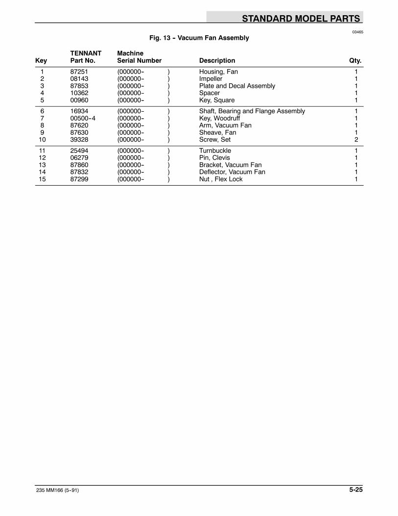
STANDARD MODEL PARTS
5-25235 MM166 (5--91)
03465
Fig. 13 -- Vacuum Fan Assembly
TENNANT MachineKey Part No. Serial Number Description Qty.
1 87251 (000000-- ) Housing, Fan 12 08143 (000000-- ) Impeller 13 87853 (000000-- ) Plate and Decal Assembly 14 10362 (000000-- ) Spacer 15 00960 (000000-- ) Key, Square 1
6 16934 (000000-- ) Shaft, Bearing and Flange Assembly 17 00500--4 (000000-- ) Key, Woodruff 18 87620 (000000-- ) Arm, Vacuum Fan 19 87630 (000000-- ) Sheave, Fan 110 39328 (000000-- ) Screw, Set 2
11 25494 (000000-- ) Turnbuckle 112 06279 (000000-- ) Pin, Clevis 113 87860 (000000-- ) Bracket, Vacuum Fan 114 87832 (000000-- ) Deflector, Vacuum Fan 115 87299 (000000-- ) Nut , Flex Lock 1

STANDARD MODEL PARTS
235 MM166 (5--91)5-26
MainFrame
12
3
5
27
28
4
67
910
11
151412
13
16
MainBrushTube
8
23
2422
2118
17
20
26
25
67
19
29
Fig. 14 -- Main Brush Drive Group

STANDARD MODEL PARTS
5-27235 MM166 (3--93)
03262
Fig. 14 -- Main Brush Drive Group
TENNANT MachineKey Part No. Serial Number Description Qty.
1 39527 (000000-- ) Nut, Slotted 12 39350 (000000-- ) Washer 13 87631 (000000-- ) Plug, Brush Drive 14 87040 (000000-- ) Shaft, Drive 15 00928 (000000-- ) Key, Square 1
6 09005 (000000-- ) Ring, Retaining 27 13534 (000000-- ) Bearing, Ball 28 87368 (000000-- ) Flange, Debris 19 87030 (000000-- ) Arm, Main Brush 110 87078 (000000-- ) Washer, Brush Arm 1
11 87027 (000000--001437 ) Sheave, Mounting Shaft (Replaced by 87267) 112 49495 (000000-- ) Sheave 113 23225 (000000--001437 ) Ring, Retaining 114 01844 (000000-- ) Bearing, Ball 115 23224 (000000-- ) Ring, Retaining 1
16 49439 (000000-- ) Sheave 117 01866 (000000-- ) Pin, Roll 118 82842 (000000-- ) Screw, Nylon Hex 119 02356 (000000-- ) Pulley, Idler 120 87474 (000000-- ) V--Belt 1
21 33123 (000000-- ) Screw, Shoulder 122 09370 (000000-- ) Pin, Clevis 123 46785--1 (000000-- ) Spring, Tension 124 87645 (000000-- ) Arm Assembly, Idler 125 87646 (000000-- ) Bearing, Bronze 1
26 30205 (000000-- ) Screw, Leveler 127 87215 (000000-- ) Housing, Bearing 128 87080 (000000-- ) Bearing 129 87267 (001438-- ) Spacer, Bearing 1
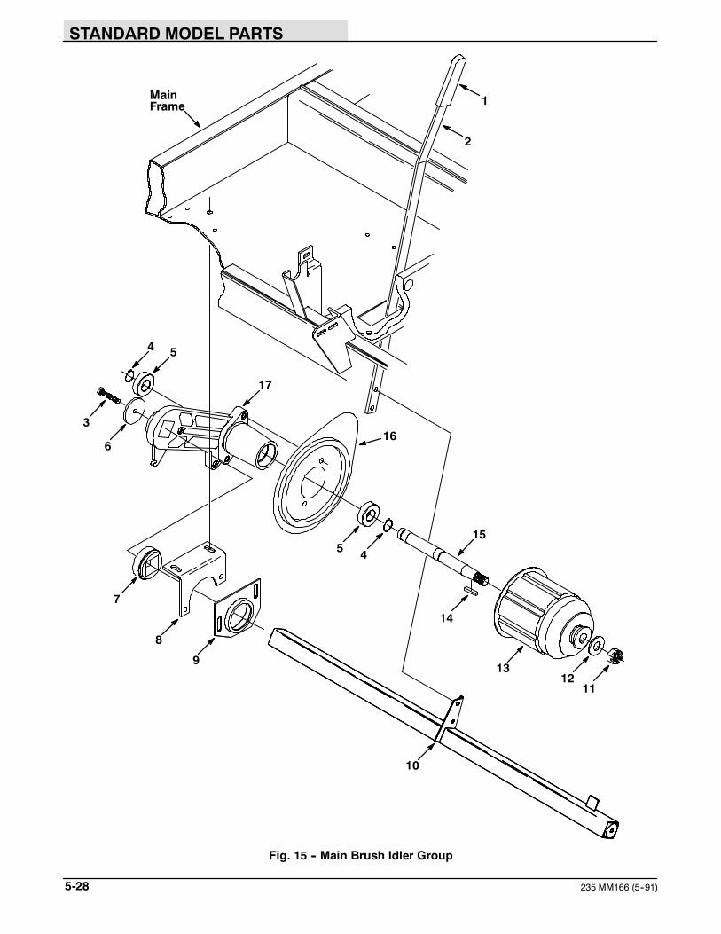
STANDARD MODEL PARTS
235 MM166 (5--91)5-28
MainFrame
2
1
4 5
3
6
17
16
5 4
15
14
131211
10
9
8
7
Fig. 15 -- Main Brush Idler Group

STANDARD MODEL PARTS
5-29235 MM166 (5--91)
03263
Fig. 15 -- Main Brush Idler Group
TENNANT MachineKey Part No. Serial Number Description Qty.
1 16447 (000000-- ) Grip, Handle 12 87275 (000000-- ) Handle, Brush Lift 13 55347 (000000-- ) Screw, Hex 14 09005 (000000-- ) Ring, Retaining 25 13534 (000000-- ) Bearing, Ball 2
6 87078 (000000-- ) Washer, Brush Arm 17 87080 (000000-- ) Bearing 18 87088 (000000-- ) Bracket, Bearing Housing 19 87215 (000000-- ) Housing, Bearing 110 87082 (000000-- ) Tube, Main Brush 1
11 39527 (000000-- ) Nut, Slotted 112 39350 (000000-- ) Washer 113 87631 (000000-- ) Plug, Brush Drive 114 00928 (000000-- ) Key, Square 115 87041 (000000-- ) Shaft, Idler 1
16 87368 (000000-- ) Flange, Debris 117 87030 (000000-- ) Arm, Main Brush 1

STANDARD MODEL PARTS
235 MM166 (5--91)5-30
26
25
27
23
22
2120SideBrush
16
19
17
10
FrontBumper
13
15
14
1211
9
8
7
6
5
3
2
1
24
MainFrame andLift Arms
4
18
6
7
28
Fig. 16 -- Side Brush Group

STANDARD MODEL PARTS
5-31235 MM166 (5--91)
03274
Fig. 16 -- Side Brush Group
TENNANT MachineKey Part No. Serial Number Description Qty.
1 16447 (000000-- ) Grip, Handle 12 87574 (000000-- ) Handle, Side Brush 13 87297 (000000-- ) Cable, Brush Adjustment 14 04734 (000000-- ) Pin, Clevis 15 45261 (000000-- ) Spring, Compression 1
6 87627 (000000-- ) Strip, Spring 27 49266 (000000-- ) Tie, Cable 38 57452 (000000-- ) Sleeve, Hydraulic 19 87298 (000000-- ) Cable, Brush Lift 110 36468 (000000-- ) Knob 1
11 36070 (000000-- ) Pulley, Cable 112 04733 (000000-- ) Pin, Clevis 113 87293 (000000-- ) Block, Threaded 114 58670 (000000-- ) Screw, Nylon Hex 115 87297 (000000-- ) Cable, Brush Adjustment 1
16 87172 (000000-- ) Cable, Side Brush 117 87170 (000000-- ) Channel, Side Brush Mounting 118 87242 (000000-- ) Spring 119 87221 (000000-- ) Bracket, Motor Mounting 120 41185 (000000-- ) Washer, Belleville 1
21 41178 (000000-- ) Washer 122 87418 (000000-- ) Mount 123 87439 (000000-- ) Deflector, Side Brush 124 87656 (000000-- ) Sleeve, Hydraulic 125 87475 (000000--001891 ) Motor, Hydraulic (See Hydraulic Components) 1
25 28804 (001892-- ) Motor, Hydraulic (See Hydraulic Components) 126 57984 (000000-- ) Fitting, Straight 227 39210 (000000-- ) Fitting, Elbow 128 87950 (000000-- ) Deflector 1

STANDARD MODEL PARTS
235 MM166 (3-94)5-32
365
1
56
4
2
12
13
7
8
11
910
1415
Fig. 17 -- Hydraulic Lift Cylinder and Filter Group

STANDARD MODEL PARTS
5-33235 MM166 (3-94)
03471
Fig. 17 -- Hydraulic Lift Cylinder and Filter Group
TENNANT MachineKey Part No. Serial Number Description Qty.
1 51787 (000000-- ) Bumper, Rubber 12 48657 (000000-- ) Bracket, Filter 13 67718 (000000-- ) Filter Assembly 14 67718--2 (000000-- ) Element, Hydraulic Filter 15 47519 (000000-- ) Fitting, Straight 2
6 55686 (000000-- ) Fitting, Straight 27 82802 (000000-- ) Fitting, Cross 18 87414 (000000-- ) Fitting, Straight 19 47638 (000000-- ) Fitting, Elbow 110 16455 (000000-- ) Fitting, Restrictor 1
11 87055 (000000--002748 ) Cylinder, Hydraulic (See Hydraulic Components) 111 48575 (002749--003295 ) Cylinder, Hydraulic (See Hydraulic Components) 111 65223 (003296-- ) Cylinder, Hydraulic (See Hydraulic Components) 112 87079 (000000-- ) Clevis, Cylinder 113 04733--4 (000000-- ) Pin, Clevis 1
14 32969 (000000-- ) Washer 115 46482 (003296-- ) Fitting, Plug 1

STANDARD MODEL PARTS
235 MM166 (5--91)5-34
22
23
21
21
1
28
2726
25
19
20
2
12
16
14
13
9
5
8
11
10
17
29
32
31
30
15
MainFrame
24
18
3
46
7
V-Belt33
Fig. 18 -- Pump Group

STANDARD MODEL PARTS
5-35235 MM166 (5--91)
03479
Fig. 18 -- Pump Group
TENNANT MachineKey Part No. Serial Number Description Qty.
1 87732 (000000-- ) Guard, Belt 12 87513 (000000-- ) Sheave, Propelling Pump 13 15280--3 (000000-- ) Bushing, Key 14 39330 (000000-- ) Screw, Set 25 87236 (000000-- ) Plate Assembly, Retaining 1
6 26103 (000000-- ) Pin, Roll 27 39332 (000000-- ) Screw, Set 28 87511 (000000-- ) Sheave, Pump 19 87474 (000000-- ) V--Belt 110 87451 (000000-- ) Pump, Accessory 1
11 47638 (000000-- ) Fitting, Elbow 112 56835 (000000-- ) Fitting, Straight 113 87521 (000000-- ) Bracket, Pump Mounting 114 87512 (000000-- ) Sheave, Pump 115 39330 (000000-- ) Screw, Set 2
16 87543 (000000-- ) V--Belt 117 87370 (000000-- ) Mount, Pump (See Hydraulic Components) 118 87365 (000000-- ) Tube, Spacer 219 87362 (000000-- ) Block, Stop 120 02218 (000000-- ) Screw, Full Thread Hex 1
21 87351 (000000-- ) Arm, Pintle Centering 222 87222 (000000-- ) Spring, Extension 223 87360 (000000-- ) Arm, Pintle 124 26103 (000000-- ) Pin, Roll 125 57984 (000000-- ) Fitting, Straight 1
26 56692 (000000-- ) Fitting, Straight 127 47508 (000000-- ) Fitting, Straight 128 42215 (000000-- ) Fitting, Tee 129 47513 (000000-- ) Fitting, Elbow, 45_ 1
87735 (000000-- ) Pump Assembly, Hydraulic 1
30 87734 (000000-- ) Pump, Hydraulic (See Hydraulic Components) 131 69159 (000000-- ) Gasket, Pump 132 69158 (000000-- ) Plate, Backing 133 86646 (000000-- ) Screw, Full Thread 2

STANDARD MODEL PARTS
235 MM166 (5--91)5-36
3
2
10
11
13
14
14
15
6
7
5
4
9
8
12
4
4
ControlPanel
1
Fig. 19 -- Control Valve and Throttle Group

STANDARD MODEL PARTS
5-37235 MM166 (5--91)
03469
Fig. 19 -- Control Valve and Throttle Group
TENNANT MachineKey Part No. Serial Number Description Qty.
1 87246 (000000-- ) Grip, Vinyl 22 87218 (000000-- ) Lever, Throttle 13 43242 (000000-- ) Swivel 14 43454 (000000-- ) Washer, Nylon 75 41178 (000000-- ) Washer, Fender 1
6 87404 (000000-- ) Bracket, Cable Guide 17 63475 (000000-- ) Cable Assembly 18 75575 (000000-- ) Spring, Tension 19 63416 (000000-- ) Washer, Rubber 110 87375 (000000-- ) Lever, Hydraulic Valve 1
11 87376 (000000-- ) Arm, Extension 112 14605 (000000-- ) Pin, Clevis 113 87409 (000000-- ) Valve, Hydraulic (See Hydraulic Components) 114 57984 (000000-- ) Fitting, Straight 215 55686 (000000-- ) Fitting, Straight 2

STANDARD MODEL PARTS
235 MM166 (8--95)5-38
3
MainFrame
5
7
6 8
4
1
2
9
10
11
03481
Fig. 20 -- Hydraulic Reservoir Group
TENNANT MachineKey Part No. Serial Number Description Qty.
1 87392 (000000-- ) Reservoir Assembly 12 31559 (000000-- ) Breather, Filler 13 61288 (000000-- ) Gasket, Hyd Tank Breather 24 25121 (000000-- ) Breather, Hyd Cap 15 70006 (000000-- ) Gasket, Cap 1
6 40362 (000000-- ) Fitting, Plug 17 87484 (000000-- ) Strap, Tank 28 82784 (000000-- ) Strainer, Hydraulic 19 47508 (000000-- ) Fitting, Straight 110 02545 (000000-- ) Fitting, Straight 1
11 13773 (000000-- ) Sleeve, Nylon 1

STANDARD MODEL PARTS
5-39235 MM166 (5--91)
15
16
1310
1
56
12
7
3
2
4
MainFrame
17
18
14
2
9
8
11
03472
Fig. 21 -- Rear Drive Wheel Group
TENNANT MachineKey Part No. Serial Number Description Qty.
1 02637 (000000-- ) Support, Drive 12 49225 (000000-- ) Bearing, Cup and Cone 13 47719 (000000-- ) Washer 14 47801 (000000-- ) Fitting, Grease 15 58842 (000000-- ) Plate, Hose Support 1
6 87676 (000000-- ) Sleeve, Hydraulic 17 14242 (000000-- ) Nut, Slotted Hex 18 87458 (000000-- ) Pin, Pivot 19 56692 (000000-- ) Fitting, Straight 210 77098 (000000-- ) Fitting, Elbow 1
11 87417 (000000-- ) Motor, Hydraulic (See Hydraulic Components) 112 82239 (000000-- ) Hub and Stud Assembly 113 32126 (000000-- ) Stud, Wheel 514 87421 (000000-- ) Tire and Wheel Assembly 115 87411 (000000-- ) Wheel 1
16 87674 (000000-- ) Tire 117 87675 (000000-- ) Valve, Tubeless Tire 118 24339 (000000-- ) Nut, Wheel 5

STANDARD MODEL PARTS
235 MM166 (5--91)5-40
AccessoryPump
PropellingPump
ControlValve
PropellingMotor
HydraulicReservoir
HydraulicFilter
HopperLiftCylinder
SideBrushMotor
5
9
8
4
2
3
6
7
4
10
1
Fig. 22 -- Hydraulic Hoses Group

STANDARD MODEL PARTS
5-41235 MM166 (5--91)
03461
Fig. 22 -- Hydraulic Hoses Group
TENNANT MachineKey Part No. Serial Number Description Qty.
1 82816 (000000-- ) Hose, Hydraulic 12 87652 (000000-- ) Hose, Hydraulic 13 87651 (000000-- ) Hose, Hydraulic 14 34358 (000000-- ) Hose, Hydraulic 25 57965 (000000-- ) Hose, Hydraulic 1
6 87672 (000000-- ) Hose, Hydraulic 17 82809 (000000-- ) Hose, Hydraulic 18 87680 (000000-- ) Hose, Hydraulic 19 87678 (000000-- ) Hose, Hydraulic 110 57219 (000000-- ) Hose, Hydraulic 2

STANDARD MODEL PARTS
235 MM166 (5--91)5-42
1
3
4
6
MainFrame
5
2
8
9
712
11
10
11
Fig. 23 -- Steering Wheel Group

STANDARD MODEL PARTS
5-43235 MM166 (3--93)
03463
Fig. 23 -- Steering Wheel Group
TENNANT MachineKey Part No. Serial Number Description Qty.
1 57497 (000000-- ) Cap, Rubber 12 49452 (000000-- ) Gear Assembly, Steering 13 87488 (000000-- ) Wheel, Steering 14 87245 (000000-- ) Bracket, Steering Column 15 14138A (000000-- ) Horn, 12 V 1
6 87257 (000000-- ) Spacer, Horn 17 51449 (000000-- ) Bearing, Flange 28 48050 (000000-- ) Bearing and Collar 19 44078 (000000-- ) Switch 110 87109 (000000-- ) Link, Drag 1
11 07259 (000000-- ) Fitting, Grease 212 87820 (000000-- ) Arm, Pitman 1

STANDARD MODEL PARTS
235 MM166 (5--91)5-44
1
MainFrame
4
6
7
9
3
5
5
8
5
2
03473
Fig. 24 -- Directional Pedal Group
TENNANT MachineKey Part No. Serial Number Description Qty.
1 87254 (000000-- ) Cover, Bellcrank 12 42240 (000000-- ) Pedal, Foot 13 87881 (000000-- ) Arm, Pedal 14 06474A (000000-- ) Pin, Clevis 15 14506 (000000-- ) Ball Joint 4
6 87155 (000000-- ) Rod, Control 17 87198 (000000-- ) Bellcrank 18 87131 (000000-- ) Rod, Control 19 82839 (000000-- ) Pad, Tread 1

STANDARD MODEL PARTS
5-45235 MM166 (5--91)
4
6
3
HopperLiftArm
3
2
57
1
03476
Fig. 25 -- Speed Limiter Group
TENNANT MachineKey Part No. Serial Number Description Qty.
1 87803 (000000-- ) Bracket, Pivot Pin 12 87491 (000000-- ) Link, Upper 13 45127 (000000-- ) Ring, Retaining 24 87804 (000000-- ) Link, Lower 15 87798 (000000-- ) Bracket, Cam Mounting 1
6 87797 (000000-- ) Cam, Speed Limiter 17 29584 (000000-- ) Pin, Clevis 1
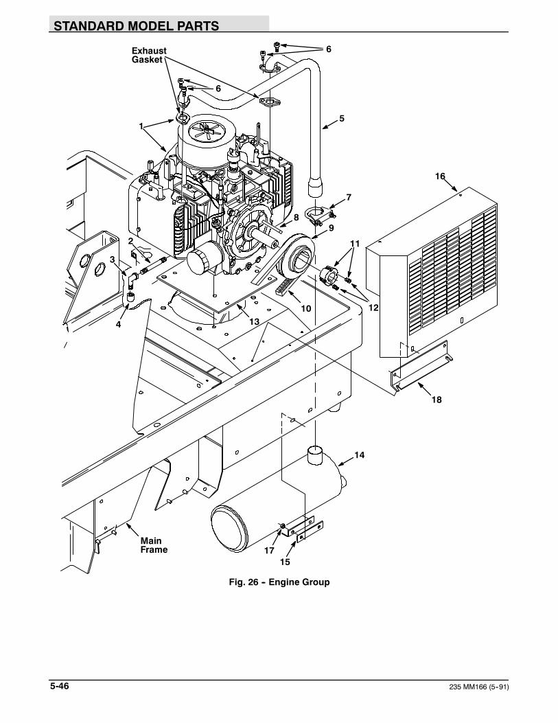
STANDARD MODEL PARTS
235 MM166 (5--91)5-46
5
1715
MainFrame
7
98
14
16
10134
3
2
1
6ExhaustGasket
11
12
6
18
Fig. 26 -- Engine Group

STANDARD MODEL PARTS
5-47235 MM166 (12--94)
03560
Fig. 26 -- Engine Group
TENNANT MachineKey Part No. Serial Number Description Qty.
1 87502 (000000-- ) Engine, Gas 11 48772 (003600-- ) Engine, Gas (California Only) 12 02283 (000000-- ) Fitting, Nipple 13 02547 (000000-- ) Fitting, Elbow 14 06431 (000000-- ) Fitting, Cap 1
5 87665 (000000-- ) Pipe, Exhaust 16 02985 (000000-- ) Screw, Socket 47 24012 (000000-- ) Clamp, Muffler 18 00934 (000000-- ) Key, Square 19 87692 (000000-- ) Sheave, Engine 1
10 87544 (000000-- ) V--Belt 111 87778 (000000-- ) Bushing, Taper Lock 112 39345 (000000-- ) Screw, Set 213 87179 (000000-- ) Plate, Engine Mounting 114 87534 (000000-- ) Muffler 1
15 87736 (000000-- ) Isolator, Muffler 116 87593 (000000-- ) Guard, Exhaust 117 87435 (000000-- ) Nut, Hex 218 87876 (000000-- ) Bracket, Mount 1

STANDARD MODEL PARTS
235 MM166 (5--91)5-48
9
MainFrame
86
2
3
Engine
1
12
11
10
7
1314
5
4
15
Fig. 27 -- Fuel Tank and Line Group

STANDARD MODEL PARTS
5-49235 MM166 (5--91)
03474
Fig. 27 -- Fuel Tank and Line Group
TENNANT MachineKey Part No. Serial Number Description Qty.
1 87394 (000000-- ) Tank, Fuel 12 87740 (000000-- ) Cap, Fuel Tank 13 07875 (000000-- ) Sending Unit Kit 14 14131 (000000-- ) Gasket 15 69736 (000000--001266) Fitting, Straight 1
6 32376 (000000-- ) Fitting, Elbow, 45_ 17 08876 (000000--001266) Cock Replacement Kit 18 62050 (000000-- ) Filter Assembly, Fuel 19 87764 (000000-- ) Fuel Line 110 43844 (000000-- ) Clamp, Worm Drive 2
11 82526 (000000-- ) Hose, Fuel Line 112 76736 (000000-- ) Clamp, Cable 113 48144 (001267-- ) Fitting, Nipple 114 08873 (001267-- ) Valve, Ball 115 87396 (000000-- ) Strap, Tank 2

STANDARD MODEL PARTS
235 MM166 (3-94)5-50
2
3
4
56
7
8
9
10
1
11
12
13
14
15
16
17
19
7
17
18
Fig. 28 -- Battery and Air Intake Group
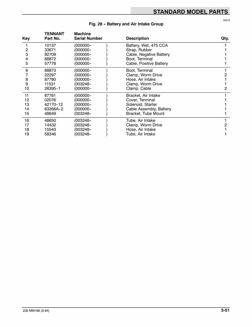
STANDARD MODEL PARTS
5-51235 MM166 (3-94)
03515
Fig. 28 -- Battery and Air Intake Group
TENNANT MachineKey Part No. Serial Number Description Qty.
1 10137 (000000-- ) Battery, Wet, 475 CCA 12 33671 (000000-- ) Strap, Rubber 13 82709 (000000-- ) Cable, Negative Battery 14 68872 (000000-- ) Boot, Terminal 15 57778 (000000-- ) Cable, Positive Battery 1
6 68873 (000000-- ) Boot, Terminal 17 22297 (000000-- ) Clamp, Worm Drive 28 87780 (000000-- ) Hose, Air Intake 19 11531 (003248-- ) Clamp, Worm Drive 110 26395--1 (000000-- ) Clamp, Cable 2
11 87781 (000000-- ) Bracket, Air Intake 112 02076 (000000-- ) Cover, Terminal 113 42170--12 (000000-- ) Solenoid, Starter 114 63266A--2 (000000-- ) Cable Assembly, Battery 115 48649 (003248-- ) Bracket, Tube Mount 1
16 48650 (003248-- ) Tube, Air Intake 117 14432 (003248-- ) Clamp, Worm Drive 218 15543 (003248-- ) Hose, Air Intake 119 58346 (003248-- ) Tube, Air Intake 1

STANDARD MODEL PARTS
235 MM166 (5--91)5-52
4
3
2
5
1415
20
7
1
MainFrame
6
98 1011
12
18
16
1719
18
1317
21
Fig. 29 -- Control Panel Group

STANDARD MODEL PARTS
5-53235 MM166 (3--93)
03364
Fig. 29 -- Control Panel Group
TENNANT MachineKey Part No. Serial Number Description Qty.
1 87021 (000000-- ) Panel and Label Assembly, Control 12 34813 (000000-- ) Gauge, Fuel 13 55271 (000000-- ) Light Assembly 1
48570 (000000-- ) Bulb, 12 V 14 55272 (000000-- ) Plug, Snap Terminal 1
5 34810 (000000-- ) Gauge, Hour Meter 16 87283 (000000-- ) Relay 17 40678--1 (000000-- ) Clamp, Cable 28 17409 (000000-- ) Cable Assembly, Choke 19 87250 (000000-- ) Switch, Ignition 1
87865 (000000-- ) Key Set 110 31965 (000000-- ) Switch, Rocker, SPST 111 31964 (000000-- ) Switch, Rocker, DPDT 112 57807 (000000-- ) Seal, Rocker Switch 213 64141 (000000-- ) Light Assembly, Panel 3
14 87637 (000000-- ) Label, Control Panel 115 87369 (000000-- ) Stop, Seat Support 116 57751 (000000-- ) Boot, Circuit Breaker 617 57164 (000000-- ) Circuit Breaker,10 A 318 57803 (000000-- ) Circuit Breaker,15 A 2
19 87977 (000000-- ) Circuit Breaker, 7 A 120 62595--18 (000000-- ) Molding, Rigid 121 48568 (000000-- ) Nut, Speed Limiter 1

STANDARD MODEL PARTS
235 MM166 (3-94)5-54
3
2
1
4
Fig. 30 -- Wire Harness Group

STANDARD MODEL PARTS
5-55235 MM166 (3-94)
2
2
2
5
2
2
03598
Fig. 30 -- Wire Harness Group
TENNANT MachineKey Part No. Serial Number Description Qty.
1 87552 (000000-- ) Wire Harness, Hopper 12 87345 (000000-- ) Wire Harness, Main 13 87650 (000000-- ) Wire Harness, Taillights 14 87603 (000000-- ) Wire Harness, Engine 15 87052 (000000-- ) Sensor, Charge Indicator 1

STANDARD MODEL PARTS
235 MM166 (3--93)5-56
2
11
3
1
4
03600
Fig. 31 -- Labels Group
TENNANT MachineKey Part No. Serial Number Description Qty.
1 87640 (000000-- ) Label Kit, Information and Hazard 12 87639 (000000-- ) Label Kit, Operation 13 08885 (000000-- ) Label, Warning, Emissions 14 87356 (000000-- ) Label, Lintel, 235 1
87954 (000000-- ) Label, Replacement Kit, Gasoline 1
87955 (000000-- ) Label, Replacement Kit, LPG 1

LPG PARTS
6-1235 MM166 (5--91)
SECTION 6CONTENTS
PageORDERING REPAIR PARTS 6--3. . . . . . . . . . . .Fig. 1 -- Engine and Fuel Line
Group, LPG 6--4. . . . . . . . . . . . . . . .Fig. 2 -- Control Panel Group, LPG 6--6. . . . . . . .
NOTE: Section 6, LPG Parts, lists repair parts uniqueto an LPG powered machine.

LPG PARTS
235 MM166 (5--91)6-2

LPG PARTS
6-3235 MM166 (5--91)
ORDERING REPAIR PARTSThe components used in this machine have beencarefully selected for performance and safety. Useonly TENNANT specified or equivalent parts.
To receive prompt service in filling of your partsorders, please direct all orders for parts withTENNANT part numbers to the TENNANT, and allorders for parts with vendor part numbers to the localsupplier of the respective vendor.
When ordering parts, please furnish all of thefollowing information:
1. Machine model number - shown on the machinedata plate.
SER.NO.
GVW. LBS. KG.
TENNANT COMPANYMINNEAPOLIS, MINN USA
2. Machine serial number - shown on the machinedata plate.
3. Power source - gasoline, LPG, diesel, electric.
4. Company name.
5. Shipping address.
6. Billing address.
7. Name, first and last - of person ordering parts.
8. Telephone number.
9. Purchase order number.
10. Part number, description, and quantity - of eachitem on the order.
11. Customer ID Number.
Do not order parts by key number or the figurenumber of the illustrated parts. Indented itemsindicate parts of assemblies. Standard hardware isfurnished only when part of a purchased assembly.Please get hardware from a local hardware supplier.
If the old part cannot be identified, send it to us withthe quantity needed specified on the order.
Any claim for loss or damage to a shipment in transitshould be filed promptly against the transportationcompany making the delivery. Shipments will becomplete unless the packing list or order ack-nowledgement indicate items back ordered.
If parts received are suspected to be incorrect ordefective, please write, wire, or phone the TENNANTrepresentative from whom you ordered the part. Theywill give authorization for return and/or handlereplacement shipments when required.
SERIAL NUMBER INFORMATION EXPLANATION
Serial number listings are shown to indicate on whichmachines each part can be used. These listings areexplained by the following examples:
(000000-- ) The part can be used on all machines.
(003342-- ) The part can be used on all machinesbeginning with the serial number listed.
(000000--004320) The part can be used on allmachines up to and including serial number listed.
(004321--005678) The part can be used on allmachines between and including the serial numberslisted.
Where xxxxxx’s are listed in place of a serial number,it indicates a change was made but the exact serialnumber had not been established when the catalogwent to press.
SI UNITS OF MEASURE(INTERNATIONAL SYSTEM)
Metric equivalents have been included, whereapplicable, throughout this parts catalog.
FASTENER STRENGTH IDENTIFICATION
Fasteners required to have high--strength qualitiesequivalent to SAE Grade 8 are identified throughoutthis catalog by the description GR 8. Unless identifiedby this description, all standard fasteners are SAEGrade 5.
(Specifications and design subject to change withoutnotice.)

LPG PARTS
235 MM166 (3-94)6-4
29
16
15
1312
10
11
20
18
1917
5
9
8
67
35
31
9
21
24
23
22
28
14
25
26
33
32
3 2
4
1
OilPressureSwitch
MainFrame
3435
30
Bracket
36373938
42
3740
41 27
Fig. 1 -- Engine and Fuel Line Group, LPG
NOTE: To identify parts shown but not listed here, see Section 5, Standard Model Parts.
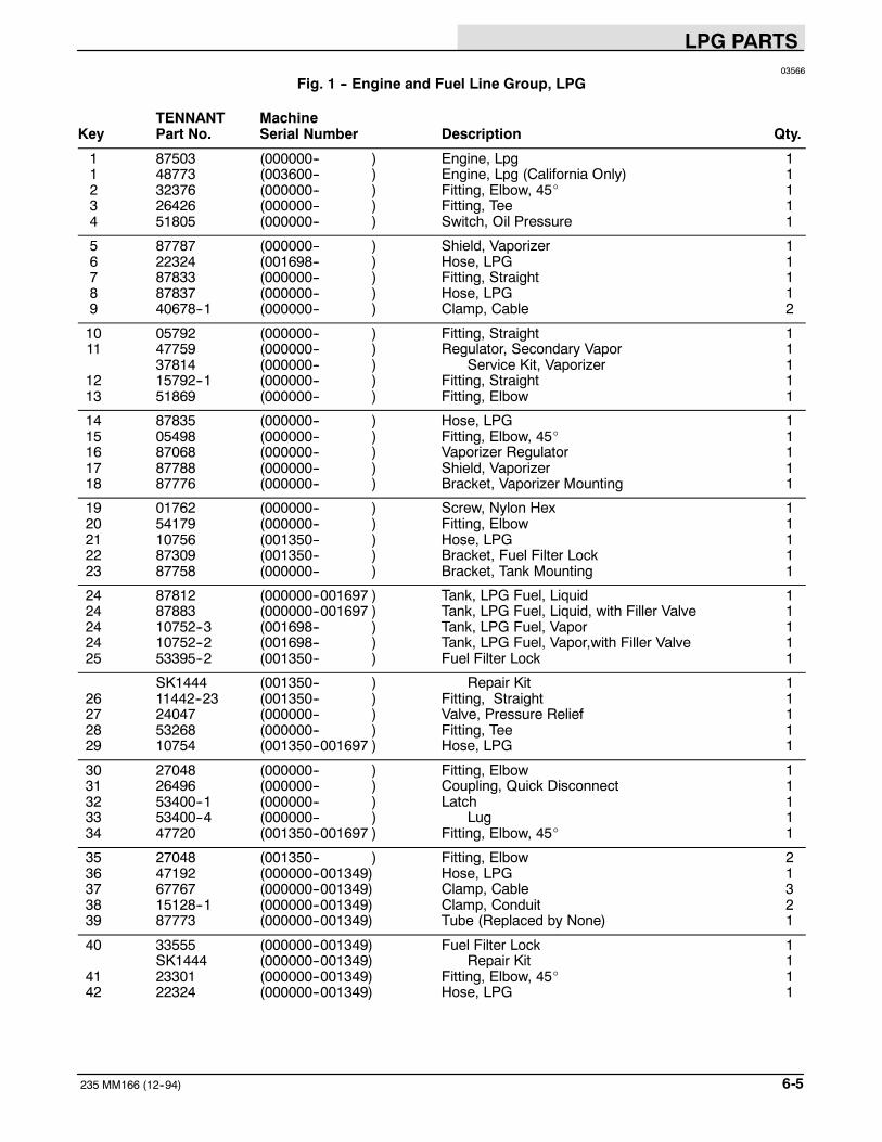
LPG PARTS
6-5235 MM166 (12--94)
03566
Fig. 1 -- Engine and Fuel Line Group, LPG
TENNANT MachineKey Part No. Serial Number Description Qty.
1 87503 (000000-- ) Engine, Lpg 11 48773 (003600-- ) Engine, Lpg (California Only) 12 32376 (000000-- ) Fitting, Elbow, 45_ 13 26426 (000000-- ) Fitting, Tee 14 51805 (000000-- ) Switch, Oil Pressure 1
5 87787 (000000-- ) Shield, Vaporizer 16 22324 (001698-- ) Hose, LPG 17 87833 (000000-- ) Fitting, Straight 18 87837 (000000-- ) Hose, LPG 19 40678--1 (000000-- ) Clamp, Cable 2
10 05792 (000000-- ) Fitting, Straight 111 47759 (000000-- ) Regulator, Secondary Vapor 1
37814 (000000-- ) Service Kit, Vaporizer 112 15792--1 (000000-- ) Fitting, Straight 113 51869 (000000-- ) Fitting, Elbow 1
14 87835 (000000-- ) Hose, LPG 115 05498 (000000-- ) Fitting, Elbow, 45_ 116 87068 (000000-- ) Vaporizer Regulator 117 87788 (000000-- ) Shield, Vaporizer 118 87776 (000000-- ) Bracket, Vaporizer Mounting 1
19 01762 (000000-- ) Screw, Nylon Hex 120 54179 (000000-- ) Fitting, Elbow 121 10756 (001350-- ) Hose, LPG 122 87309 (001350-- ) Bracket, Fuel Filter Lock 123 87758 (000000-- ) Bracket, Tank Mounting 1
24 87812 (000000--001697 ) Tank, LPG Fuel, Liquid 124 87883 (000000--001697 ) Tank, LPG Fuel, Liquid, with Filler Valve 124 10752--3 (001698-- ) Tank, LPG Fuel, Vapor 124 10752--2 (001698-- ) Tank, LPG Fuel, Vapor,with Filler Valve 125 53395--2 (001350-- ) Fuel Filter Lock 1
SK1444 (001350-- ) Repair Kit 126 11442--23 (001350-- ) Fitting, Straight 127 24047 (000000-- ) Valve, Pressure Relief 128 53268 (000000-- ) Fitting, Tee 129 10754 (001350--001697 ) Hose, LPG 1
30 27048 (000000-- ) Fitting, Elbow 131 26496 (000000-- ) Coupling, Quick Disconnect 132 53400--1 (000000-- ) Latch 133 53400--4 (000000-- ) Lug 134 47720 (001350--001697 ) Fitting, Elbow, 45_ 1
35 27048 (001350-- ) Fitting, Elbow 236 47192 (000000--001349) Hose, LPG 137 67767 (000000--001349) Clamp, Cable 338 15128--1 (000000--001349) Clamp, Conduit 239 87773 (000000--001349) Tube (Replaced by None) 1
40 33555 (000000--001349) Fuel Filter Lock 1SK1444 (000000--001349) Repair Kit 1
41 23301 (000000--001349) Fitting, Elbow, 45_ 142 22324 (000000--001349) Hose, LPG 1

LPG PARTS
235 MM166 (5--91)6-6
1
2
ControlPanel
3
4
03603
Fig. 2 -- Control Panel Group, LPG
TENNANT MachineKey Part No. Serial Number Description Qty.
1 87637 (000000-- ) Label, Control Panel, LPG 12 47178--12 (000000-- ) Plugbutton 13 87343 (001698-- ) Harness, Relay 14 57804 (001698-- ) Relay, Electrical 1
NOTE: To identify parts shown but not listed here, see Section 5, Standard Model Parts.

OPTIONS
7-1235 MM166 (3-94)
SECTION 7CONTENTS
PageORDERING REPAIR PARTS 7-3. . . . . . . . . . . . . . .Fig. 1 -- Cab Kit 7-4. . . . . . . . . . . . . . . . . . . . . . . . . . .Fig. 2 -- Overhead Guard Kit 7-5. . . . . . . . . . . . . . .Fig. 3 -- Revolving Light Kit, Overhead Guard 7-6.Fig. 4 -- Revolving Light Kit, Shroud 7-7. . . . . . . . .Fig. 5 -- Demo Kit 7-8. . . . . . . . . . . . . . . . . . . . . . . . .Fig. 6 -- Foam Filled Tire Kit 7-8. . . . . . . . . . . . . . . .Fig. 7 -- Adjustable Seat Kit 7-9. . . . . . . . . . . . . . . .Fig. 8 -- Auxiliary Side Brush Group 7-10. . . . . . . . .Fig. 9 -- Auxiliary Side Brush
Hydraulic Hose Group 7-12. . . . . . . . . .Fig. 10 -- Auxiliary Side Brush
Electrical Group 7-13. . . . . . . . . . . . . . .
NOTE: Section 7, Options lists repair parts of theavailable options.

OPTIONS
235 MM166 (3--93)7-2

OPTIONS
7-3235 MM166 (3--93)
ORDERING REPAIR PARTSThe components used in this machine have beencarefully selected for performance and safety. Useonly TENNANT specified or equivalent parts.
To receive prompt service in filling of your partsorders, please direct all orders for parts withTENNANT part numbers to the TENNANT, and allorders for parts with vendor part numbers to the localsupplier of the respective vendor.
When ordering parts, please furnish all of thefollowing information:
1. Machine model number - shown on the machinedata plate.
SER.NO.
GVW. LBS. KG.
TENNANT COMPANYMINNEAPOLIS, MINN USA
2. Machine serial number - shown on the machinedata plate.
3. Power source - gasoline, LPG, diesel, electric.
4. Company name.
5. Shipping address.
6. Billing address.
7. Name, first and last - of person ordering parts.
8. Telephone number.
9. Purchase order number.
10. Part number, description, and quantity - of eachitem on the order.
11. Customer ID Number.
Do not order parts by key number or the figurenumber of the illustrated parts. Indented itemsindicate parts of assemblies. Standard hardware isfurnished only when part of a purchased assembly.Please get hardware from a local hardware supplier.
If the old part cannot be identified, send it to us withthe quantity needed specified on the order.
Any claim for loss or damage to a shipment in transitshould be filed promptly against the transportationcompany making the delivery. Shipments will becomplete unless the packing list or order ack-nowledgement indicate items back ordered.
If parts received are suspected to be incorrect ordefective, please write, wire, or phone the TENNANTrepresentative from whom you ordered the part. Theywill give authorization for return and/or handlereplacement shipments when required.
SERIAL NUMBER INFORMATION EXPLANATION
Serial number listings are shown to indicate on whichmachines each part can be used. These listings areexplained by the following examples:
(000000-- ) The part can be used on all machines.
(003342-- ) The part can be used on all machinesbeginning with the serial number listed.
(000000--004320) The part can be used on allmachines up to and including serial number listed.
(004321--005678) The part can be used on allmachines between and including the serial numberslisted.
Where xxxxxx’s are listed in place of a serial number,it indicates a change was made but the exact serialnumber had not been established when the catalogwent to press.
SI UNITS OF MEASURE(INTERNATIONAL SYSTEM)
Metric equivalents have been included, whereapplicable, throughout this parts catalog.
FASTENER STRENGTH IDENTIFICATION
Fasteners required to have high--strength qualitiesequivalent to SAE Grade 8 are identified throughoutthis catalog by the description GR 8. Unless identifiedby this description, all standard fasteners are SAEGrade 5.
(Specifications and design subject to change withoutnotice.)

OPTIONS
235 MM166 (3--93)7-4
6
4
3
1
5
MainFrame
3
2
5
1
OverheadGuard
03357
Fig. 1 -- Cab Kit
TENNANT MachineKey Part No. Serial Number Description Qty.
87655 (000000-- ) Cab Kit, Soft Side 11 87657 (000000-- ) Cab, Soft Side 12 87697 (000000-- ) Windshield 13 87698 (000000-- ) Channel, Side 24 87701 (000000-- ) Channel, Bottom 1
5 87694 (000000-- ) Snap, Male 296 87695 (000000-- ) Snap, Male 4
NOTE: To Identify parts shown but not listed here, see Section 5, Standard Model Parts.

OPTIONS
7-5235 MM166 (3--93)
3
1
MainFrame
2
4
4
03355
Fig. 2 -- Overhead Guard Kit
TENNANT MachineKey Part No. Serial Number Description Qty.
87829 (000000-- ) Guard Kit, Overhead 11 87450 (000000-- ) Guard, Overhead 12 87742 (000000-- ) Molding, Rigid 23 62595--21 (000000-- ) Molding, Rigid 14 36328 (000000-- ) Washer, Belleville 2
NOTE: To Identify parts shown but not listed here, see Section 5, Standard Model Parts.

OPTIONS
235 MM166 (3--93)7-6
ControlPanel
OverheadGuard
54
7 6
1
2 3
03571
Fig. 3 -- Revolving Light Kit, Overhead Guard
TENNANT MachineKey Part No. Serial Number Description Qty.
87792 (000000-- ) Light Kit, Revolving Amber 11 87789 (000000-- ) Light, Revolving Amber 1
44681--1 (000000-- ) Lens, Amber 145779 (000000-- ) Bulb 1
2 10632--12 (000000-- ) Grommet 1
3 87649 (000000-- ) Wire Harness, Overhead Guard 14 87673 (000000-- ) Duct, Vinyl 15 49266 (000000-- ) Tie, Cable 26 55264 (000000-- ) Switch,Toggle 17 87174 (000000-- ) Label, Hazard Light 1
44681 (000000-- ) Lens, Revolving Light, Red 144681--2 (000000-- ) Lens, Revolving Light, Blue 1
NOTE: To Identify parts shown but not listed here, see Section 5, Standard Model Parts.

OPTIONS
7-7235 MM166 (3--93)
2
3
1
67
5
4
Shroud
ControlPanel
8
03570
Fig. 4 -- Revolving Light Kit, Shroud
TENNANT MachineKey Part No. Serial Number Description Qty.
87791 (000000-- ) Light Kit, Revolving Amber 11 87789 (000000-- ) Light, Revolving Amber 1
44681--1 (000000-- ) Lens, Amber 145779 (000000-- ) Bulb 1
2 10127 (000000-- ) Grommet 1
3 87649 (000000-- ) Wire Harness, Shroud 14 26395--2 (000000-- ) Clamp, Cable 15 49266 (000000-- ) Tie, Cable 56 55264 (000000-- ) Switch, Toggle 17 87174 (000000-- ) Label, Hazard Light 1
8 55248 (000000-- ) Mount, Cable Tie 144681 (000000-- ) Lens, Revolving Light, Red 144681--2 (000000-- ) Lens, Revolving Light, Blue 1
NOTE: To Identify parts shown but not listed here, see Section 5, Standard Model Parts.

OPTIONS
235 MM166 (3--93)7-8
MainFrame
2
1
3
4
03362
Fig. 5 -- Demo Kit
TENNANT MachineKey Part No. Serial Number Description Qty.
87790 (000000-- ) Demo Kit 11 87083 (000000--001045 ) Bracket, Replacement Kit, Rear (set of 2) 12 45079 (000000-- ) Bracket, Tie--Down 23 45079 (001046-- ) Bracket, Tie--Down 24 87462 (000000-- ) Knob 3
1
03581
Fig. 6 -- Foam Filled Tire Kit
TENNANT MachineKey Part No. Serial Number Description Qty.
1 87432 (000000-- ) Tire and Wheel Assembly, Foam Filled 1
NOTE: To Identify parts shown but not listed here, see Section 5, Standard Model Parts.

OPTIONS
7-9235 MM166 (3--93)
2
34
1
2
2
2
08660
Fig. 7 -- Adjustable Seat Kit
TENNANT MachineKey Part No. Serial Number Description Qty.
48685 (000000-- ) Adjustable Seat Kit 11 66099 (000000-- ) Plate, Seat Support 12 52615 (000000-- ) Spacer, Seat Adjuster 43 51459 (000000-- ) Adjuster, Seat 14 51458 (000000-- ) Adjuster Assembly, Seat 1

OPTIONS
235 MM166 (3-94)7-10
1
1
2
3
3
5
6
7 8
9
10
11
12
131415
1617
18
19
41
20
21
22
22
23
23
24
25
2628
29303132
34
3536
37
38
3940
40
33
3327
27
4
4
FromControlValve
To StandardSide Brush
From Backof Hopper
From Backof Hopper
Fig. 8 -- Auxiliary Side Brush Group

OPTIONS
7-11235 MM166 (3-94)
06854
Fig. 8 -- Auxiliary Side Brush Group
TENNANT MachineKey Part No. Serial Number Description Qty.
1 43499 (000000-- ) Bracket 22 48582 (000000-- ) Bracket, Bulkhead 13 48580 (000000-- ) Bracket 24 06678 (000000-- ) Fitting, Straight 25 48556 (000000-- ) Cross Member, Front 1
6 35273 (000000-- ) Pin, Hitch 17 35278 (000000-- ) Pin, Hitch 18 51534 (000000-- ) Pin, Clevis 19 35280 (000000-- ) Seal, Foam Rubber 110 34219 (000000-- ) Insulation, Foam 1
11 35279 (000000-- ) Cover, Actuator 112 87444 (000000-- ) Actuator 113 82229 (000000-- ) Sleeve 214 35274 (000000-- ) Lever, Actuator 115 48567 (000000-- ) Pivot, Brush Arm 1
16 45097 (000000-- ) Bearing 217 15173 (000000-- ) Pin, Clevis 118 48581 (000000-- ) Cable 119 28804 (000000-- ) Motor, Hydraulic 120 06474A (000000-- ) Pin, Clevis 1
21 48584 (000000-- ) Bracket, Motor 122 58494 (000000-- ) Stud, Ball 223 64595 (000000-- ) Clip, Spring 224 31182 (000000-- ) Spring, Gas 125 57984 (000000-- ) Fitting, Straight 2
26 87677 (000000-- ) Sleeve, Nylon 127 34413 (000000-- ) Coupling, Male 228 49266 (000000-- ) Tie, Cable 629 87439 (000000-- ) Deflecter 130 87418 (000000-- ) Hub, Side Brush 1
31 41178 (000000-- ) Washer 132 41185 (000000-- ) Washer, Belleville 133 34414 (000000-- ) Coupling, Female 234 48587 (000000-- ) Actuator 135 48557 (000000-- ) Arm, Extended Reach 1
36 02965 (000000-- ) Sleeve 137 43560 (000000-- ) Clamp, Cable 138 23683 (000000-- ) Pin, Clevis 139 10632 (000000-- ) Grommet 140 82621 (000000-- ) Fitting, Bulkhead 2
41 23683 (000000-- ) Pin, Clevis 149287 (000000-- ) Clamp, Cable 127184 (000000-- ) Blade, Connector 248563 (000000-- ) Wire Harness, Aux Side Brush 1

OPTIONS
235 MM166 (3-94)7-12
1
2 3
4
06852
Fig. 9 -- Auxiliary Side Brush Hydraulic Hose Group
TENNANT MachineKey Part No. Serial Number Description Qty.
1 57967 (000000-- ) Hose, Hydraulic 12 48617 (000000-- ) Hose, Hydraulic 13 57947 (000000-- ) Hose, Hydraulic 14 19634 (000000-- ) Hose, Hydraulic 1

OPTIONS
7-13235 MM166 (3-94)
1
23
45
06853
Fig. 10 -- Auxiliary Side Brush Electrical Group
TENNANT MachineKey Part No. Serial Number Description Qty.
1 35304 (000000-- ) Label, Brush Control 12 65560 (000000-- ) Switch, Rocker, DPDT 23 57807 (000000-- ) Cover, Rocker Switch Seal 24 27920 (000000-- ) Breaker, Circuit, 5A 15 57751 (000000-- ) Boot, Circuit Breaker 1

OPTIONS
235 MM166 (3-94)7-14

HYDRAULIC COMPONENTS
8-1235 MM166 (3-94)
SECTION 8CONTENTS
PageORDERING REPAIR PARTS 8-3. . . . . . . . . . . . . . .Fig. 1 -- Hydraulic Motor Breakdown, 87417 8-4. . .Fig. 2 -- Hydraulic Motor Breakdown, 87475 8-5. . .Fig. 3 -- Hydraulic Valve Breakdown, 87409 8-6. . .Fig. 4 -- Hydraulic Pump Breakdown, 87734 8-7. . .Fig. 5 -- Hydraulic Lift Cylinder Breakdown,
87055 8-8. . . . . . . . . . . . . . . . . . . . . . . .Fig. 6 -- Hydraulic Lift Cylinder Breakdown,
48575 8-9. . . . . . . . . . . . . . . . . . . . . . . .Fig. 7 -- Hydraulic Lift Cylinder Breakdown,
65223 8-10. . . . . . . . . . . . . . . . . . . . . . . .Fig. 8 -- Hydraulic Pump Breakdown, 87451 8-11. . .Fig. 9 -- Hydraulic Motor Breakdown, 28804 8-12. . .
NOTE: Section 8, Hydraulic Components, lists therepair parts for each of the repairable hydrauliccomponents.

HYDRAULIC COMPONENTS
235 MM166 (3--93)8-2

HYDRAULIC COMPONENTS
8-3235 MM166 (3--93)
ORDERING REPAIR PARTSThe components used in this machine have beencarefully selected for performance and safety. Useonly TENNANT specified or equivalent parts.
To receive prompt service in filling of your partsorders, please direct all orders for parts withTENNANT part numbers to the TENNANT, and allorders for parts with vendor part numbers to the localsupplier of the respective vendor.
When ordering parts, please furnish all of thefollowing information:
1.Machine model number - shown on the machinedata plate.
SER.NO.
GVW. LBS. KG.
TENNANT COMPANYMINNEAPOLIS, MINN USA
2.Machine serial number - shown on the machinedata plate.
3.Power source - gasoline, LPG, diesel, electric.
4.Company name.
5.Shipping address.
6.Billing address.
7.Name, first and last - of person ordering parts.
8.Telephone number.
9.Purchase order number.
10. Part number, description, and quantity - of eachitem on the order.
11. Customer ID Number.
Do not order parts by key number or the figurenumber of the illustrated parts. Indented itemsindicate parts of assemblies. Standard hardware isfurnished only when part of a purchased assembly.Please get hardware from a local hardware supplier.
If the old part cannot be identified, send it to us withthe quantity needed specified on the order.
Any claim for loss or damage to a shipment in transitshould be filed promptly against the transportationcompany making the delivery. Shipments will becomplete unless the packing list or order ack-nowledgement indicate items back ordered.
If parts received are suspected to be incorrect ordefective, please write, wire, or phone the TENNANTrepresentative from whom you ordered the part. Theywill give authorization for return and/or handlereplacement shipments when required.
SERIAL NUMBER INFORMATION EXPLANATION
Serial number listings are shown to indicate on whichmachines each part can be used. These listings areexplained by the following examples:
(000000-- ) The part can be used on all machines.
(003342-- ) The part can be used on all machinesbeginning with the serial number listed.
(000000--004320) The part can be used on allmachines up to and including serial number listed.
(004321--005678) The part can be used on allmachines between and including the serial numberslisted.
Where xxxxxx’s are listed in place of a serial number,it indicates a change was made but the exact serialnumber had not been established when the catalogwent to press.
SI UNITS OF MEASURE(INTERNATIONAL SYSTEM)
Metric equivalents have been included, whereapplicable, throughout this parts catalog.
FASTENER STRENGTH IDENTIFICATION
Fasteners required to have high--strength qualitiesequivalent to SAE Grade 8 are identified throughoutthis catalog by the description GR 8. Unless identifiedby this description, all standard fasteners are SAEGrade 5.
(Specifications and design subject to change withoutnotice.)

HYDRAULIC COMPONENTS
235 MM166 (3--93)8-4
1
1 11
1
2
3
4
5 6
7 8 910
11
12
03604
Fig. 1 -- Hydraulic Motor Breakdown, 87417
TENNANT ManufactureKey Part No. Serial Number Description Qty.
87417 (000000-- ) Motor, Hydraulic 11 02643 (000000-- ) Seal Kit 12 02644 (000000-- ) Shaft And Bearing Kit 13 87784 (000000-- ) Drive 14 87785 (000000-- ) Geroler 1
5 57370 (000000-- ) Valve Drive 16 02646 (000000-- ) Valve Plate 17 02647 (000000-- ) Valve 18 57373 (000000-- ) Balance Ring 19 57374 (000000-- ) Pin 2
10 57375 (000000-- ) Spring 211 38315 (000000-- ) Key 112 38490 (000000-- ) Nut 1

HYDRAULIC COMPONENTS
8-5235 MM166 (3--93)
1
2
2
2
3
4
5
6 7
8
03563
Fig. 2 -- Hydraulic Motor Breakdown, 87475
TENNANT ManufactureKey Part No. Serial Number Description Qty.
87475 (000000-- ) Motor, Hydraulic (Replaced by 28804) 11 34174 (000000-- ) Flange, Mounting 12 47649 (000000-- ) Seal Kit 13 87662 (000000-- ) Shaft, Output 14 34176 (000000-- ) Drive 1
5 87663 (000000-- ) Geroter 16 16695 (000000-- ) Race, Thrust 17 45628 (000000-- ) Bearing, Thrust 18 00500--15 (000000-- ) Key, Woodruff 1

HYDRAULIC COMPONENTS
235 MM166 (3--93)8-6
3
2
1
03480
Fig. 3 -- Hydraulic Valve Breakdown, 87409
TENNANT ManufactureKey Part No. Serial Number Description Qty.
87409 (000000-- ) Valve, Hydraulic 11 01666 (000000-- ) Seal Kit 12 87754 (000000-- ) Relief Valve Kit 13 01669 (000000-- ) Detent Kit 1
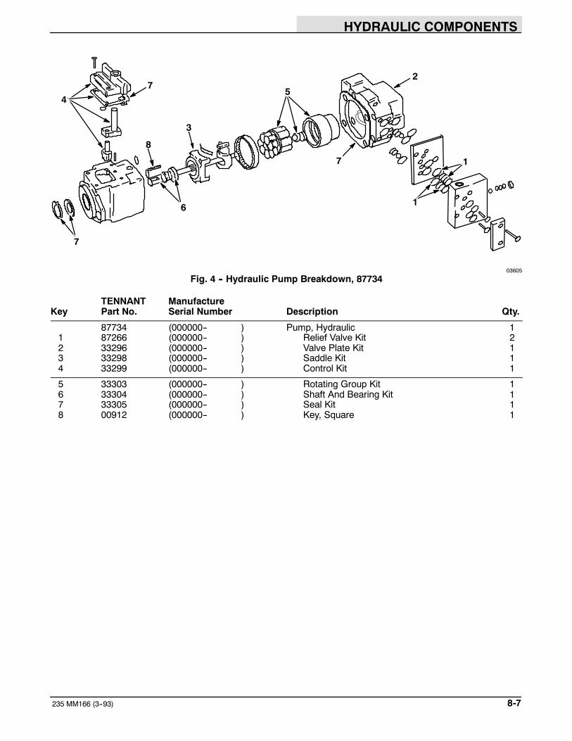
HYDRAULIC COMPONENTS
8-7235 MM166 (3--93)
7
8
3
2
7
6 1
1
47
5
03605
Fig. 4 -- Hydraulic Pump Breakdown, 87734
TENNANT ManufactureKey Part No. Serial Number Description Qty.
87734 (000000-- ) Pump, Hydraulic 11 87266 (000000-- ) Relief Valve Kit 22 33296 (000000-- ) Valve Plate Kit 13 33298 (000000-- ) Saddle Kit 14 33299 (000000-- ) Control Kit 1
5 33303 (000000-- ) Rotating Group Kit 16 33304 (000000-- ) Shaft And Bearing Kit 17 33305 (000000-- ) Seal Kit 18 00912 (000000-- ) Key, Square 1

HYDRAULIC COMPONENTS
235 MM166 (3--93)8-8
2
3
1
1
1
08680
Fig. 5 -- Hydraulic Lift Cylinder Breakdown, 87055
TENNANT ManufactureKey Part No. Serial Number Description Qty.
87055 (000000-- ) Cylinder, Hydraulic (Replaced by 48575) 11 87744 (000000-- ) Seal Kit 12 87850 (000000-- ) Pin, Clevis 13 87851 (000000-- ) Pin, Hair Cotter 1
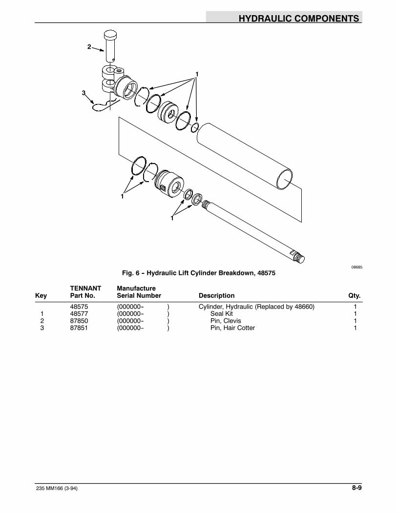
HYDRAULIC COMPONENTS
8-9235 MM166 (3-94)
2
3
1
1
1
08685
Fig. 6 -- Hydraulic Lift Cylinder Breakdown, 48575
TENNANT ManufactureKey Part No. Serial Number Description Qty.
48575 (000000-- ) Cylinder, Hydraulic (Replaced by 48660) 11 48577 (000000-- ) Seal Kit 12 87850 (000000-- ) Pin, Clevis 13 87851 (000000-- ) Pin, Hair Cotter 1
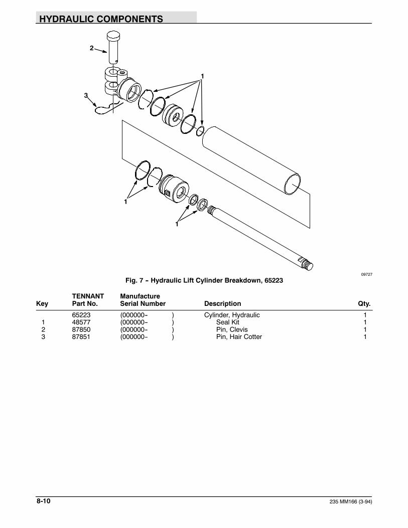
HYDRAULIC COMPONENTS
235 MM166 (3-94)8-10
2
3
1
1
1
09727
Fig. 7 -- Hydraulic Lift Cylinder Breakdown, 65223
TENNANT ManufactureKey Part No. Serial Number Description Qty.
65223 (000000-- ) Cylinder, Hydraulic 11 48577 (000000-- ) Seal Kit 12 87850 (000000-- ) Pin, Clevis 13 87851 (000000-- ) Pin, Hair Cotter 1
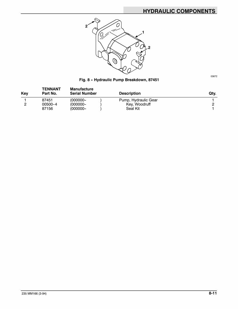
HYDRAULIC COMPONENTS
8-11235 MM166 (3-94)
21
2
03672
Fig. 8 -- Hydraulic Pump Breakdown, 87451
TENNANT ManufactureKey Part No. Serial Number Description Qty.
1 87451 (000000-- ) Pump, Hydraulic Gear 12 00500--4 (000000-- ) Key, Woodruff 2
87156 (000000-- ) Seal Kit 1

HYDRAULIC COMPONENTS
235 MM166 (3-94)8-12
1
2
2
2
3
4
5
6
05608
Fig. 9 -- Hydraulic Motor Breakdown, 28804
TENNANT ManufactureKey Part No. Serial Number Description Qty.
28804 (000000-- ) Motor, Hydraulic 11 31354 (000000-- ) Flange, Mounting 12 28835 (000000-- ) Seal Kit 13 87662 (000000-- ) Shaft, Output 14 34176 (000000-- ) Drive 1
5 50186 (000000-- ) Geroter Set 16 00500--15 (000000-- ) Key, Woodruff 1

ENGINE PARTS, GASOLINE, LPG
9-1235 MM166 (3--93)
SECTION 9CONTENTS
PageORDERING REPAIR PARTS 9-3. . . . . . . . . . . . . . .Fig. 1 -- Crankcase Group 9-4. . . . . . . . . . . . . . . . . .Fig. 2 -- Cylinder Head Group 9-6. . . . . . . . . . . . . . .Fig. 3 -- Camshaft and Valves Group 9-7. . . . . . . .Fig. 4 -- Crankshaft and Flywheel Group 9-8. . . . .Fig. 5 -- Baffles and Shroud Group 9-9. . . . . . . . . .Fig. 6 -- Dipstick and Oil Filter Group 9-10. . . . . . . .Fig. 7 -- Oil Pump Group 9-11. . . . . . . . . . . . . . . . . . .Fig. 8 -- Breather and Vent Group 9-12. . . . . . . . . . .Fig. 9 -- Fuel Pump Group 9-13. . . . . . . . . . . . . . . . .Fig. 10 -- Carburetor Group 9-14. . . . . . . . . . . . . . . . .Fig. 11 -- Air Intake Group 9-16. . . . . . . . . . . . . . . . . .Fig. 12 -- Governor Group 9-17. . . . . . . . . . . . . . . . . .Fig. 13 -- Ignition Group 9-18. . . . . . . . . . . . . . . . . . . .Fig. 14 -- Starter Group 9-19. . . . . . . . . . . . . . . . . . . . .
NOTE: Section 9, Engine Parts, Gasoline, LPG, liststhe repair parts for the gasoline engine, TENNANTPart No. 87502 and the LPG engine, TENNANT PartNo. 87503.

ENGINE PARTS, GASOLINE, LPG
235 MM166 (3--93)9-2

ENGINE PARTS, GASOLINE, LPG
9-3235 MM166 (3--93)
ORDERING REPAIR PARTSThe components used in this machine have beencarefully selected for performance and safety. Useonly TENNANT specified or equivalent parts.
To receive prompt service in filling of your partsorders, please direct all orders for parts withTENNANT part numbers to the TENNANT, and allorders for parts with vendor part numbers to the localsupplier of the respective vendor.
When ordering parts, please furnish all of thefollowing information:
1.Machine model number - shown on the machinedata plate.
SER.NO.
GVW. LBS. KG.
TENNANT COMPANYMINNEAPOLIS, MINN USA
2.Machine serial number - shown on the machinedata plate.
3.Power source - gasoline, LPG, diesel, electric.
4.Company name.
5.Shipping address.
6.Billing address.
7.Name, first and last - of person ordering parts.
8.Telephone number.
9.Purchase order number.
10. Part number, description, and quantity - of eachitem on the order.
11. Customer ID Number.
Do not order parts by key number or the figurenumber of the illustrated parts. Indented itemsindicate parts of assemblies. Standard hardware isfurnished only when part of a purchased assembly.Please get hardware from a local hardware supplier.
If the old part cannot be identified, send it to us withthe quantity needed specified on the order.
Any claim for loss or damage to a shipment in transitshould be filed promptly against the transportationcompany making the delivery. Shipments will becomplete unless the packing list or order ack-nowledgement indicate items back ordered.
If parts received are suspected to be incorrect ordefective, please write, wire, or phone the TENNANTrepresentative from whom you ordered the part. Theywill give authorization for return and/or handlereplacement shipments when required.
SERIAL NUMBER INFORMATION EXPLANATION
Serial number listings are shown to indicate on whichmachines each part can be used. These listings areexplained by the following examples:
(0000000000-- ) The part can be used on allmachines.
(003342-- ) The part can be used on all machinesbeginning with the serial number listed.
(0000000000--004320) The part can be used on allmachines up to and including serial number listed.
(004321--005678) The part can be used on allmachines between and including the serial numberslisted.
Where xxxxxx’s are listed in place of a serial number,it indicates a change was made but the exact serialnumber had not been established when the catalogwent to press.
SI UNITS OF MEASURE(INTERNATIONAL SYSTEM)
Metric equivalents have been included, whereapplicable, throughout this parts catalog.
FASTENER STRENGTH IDENTIFICATION
Fasteners required to have high--strength qualitiesequivalent to SAE Grade 8 are identified throughoutthis catalog by the description GR 8. Unless identifiedby this description, all standard fasteners are SAEGrade 5.
(Specifications and design subject to change withoutnotice.)

ENGINE PARTS, GASOLINE, LPG
235 MM166 (3--93)9-4
1 2
3
4
5
67 8
9
10
11
1213
14 15
1617
1819
20
2122
23
2425
26
27
28
2930
31
32
3334
35
36
37
3839
40
17
8
11
31
Fig. 1 -- Crankcase Group

ENGINE PARTS, GASOLINE, LPG
9-5235 MM166 (8--95)
03582
Fig. 1 -- Crankcase Group
TENNANT Kohler EngineKey Part No. Part Number Serial Number Description Qty.
1 52314 52--041--14 (0000000000-- ) Gasket, Exhaust 22 87888 47--703--01 (0000000000-- ) Cutout Kit, High Temp 13 47--468--07 (0000000000-- ) Washer, Flat 1
25--518--15 (0000000000-- ) Lead, Black, High Temp Cutout Switch 14 87889 52--099--06 (0000000000-- ) Switch, Low Oil Pressure 1
5 87226 52--158--05 (0000000000-- ) Reducer 125--113--05 (0000000000-- ) Decal, Oil Sentry Protection 152--518--13 (0000000000-- ) Lead, Green, Pressure Switch 1
6 X--269--43 (0000000000-- ) Ring, Retaining 17 52--078--05 (0000000000-- ) Shaft, Governor 1
8 87894 52--522--69 (0000000000-- ) Short Block 187895 52--755--94 (0000000000-- ) Gasket Set 1
9 52--139--07 (0000000000-- ) Plug 110 25--086--12 (0000000000-- ) Screw 2
87890 52--755--51 (0000000000--1917809295 ) Barrel Kit, Cylinder 2
38615 230265 (0000000000--1917809295 ) Insert, Valve Seat 442351 52--316--06 (0000000000--1917809295 ) Guide, Valve 4
52--158--04 (0000000000--1917809295 ) Bushing, Locating 211 21777 (1917809296-- ) Barrel Kit, Cylinder 111 21778 82--755--16 (1917809296-- ) Barrel Kit, Cylinder, #1 111 21779 82--755--17 (1917809296-- ) Barrel Kit, Cylinder, #2 1
12 52--031--01 (1917809296-- ) Insert, Valve Seat 413 52--316--06 (1917809296-- ) Guide, Valve 414 52--158--04 (1917809296-- ) Bushing, Locating 215 X--75--10 (0000000000-- ) Plug 116 87896 52--032--10 (0000000000-- ) Seal, Front Oil 1
17 52309 52--030--10 (0000000000-- ) Bearing, Sleeve 217 52311 52--030--11 (0000000000-- ) Bearing, Sleeve, 0.010” 217 52313 52--030--12 (0000000000-- ) Bearing, Sleeve, 0.020” 218 X--75--32 (0000000000-- ) Plug 119 52--095--03 (0000000000-- ) Housing, Oil Pickup 1
20 52--237--02 (0000000000-- ) Clip, Spring 121 52--123--10 (0000000000-- ) Tube, Oil Pickup 122 52--237--05 (0000000000-- ) Clamp, Tube 123 X--67--64 (0000000000-- ) Screw 124 52--139--08 (0000000000-- ) Plug 1
25 52--141--02 (0000000000-- ) O--Ring 126 X--702--15 (0000000000-- ) Plug, Cup 127 87893 52--755--50 (0000000000-- ) Relief Kit, Oil 128 25--086--11 (0000000000-- ) Screw 629 41--468--01 (0000000000-- ) Washer, Flat 4
30 X--352--33 (0000000000-- ) Stud 231 X--82--2 (0000000000-- ) Nut 632 25--086--13 (0000000000-- ) Screw 233 52--468--12 (0000000000-- ) Washer, Flat 1234 52--072--12 (0000000000-- ) Stud, Step 12
35 25--086--10 (0000000000-- ) Screw 336 87892 52--041--15 (0000000000-- ) Gasket, Closure Plate 137 87891 52--755--57 (0000000000-- ) Plate Kit, Closure 138 X--75--23 (0000000000-- ) Plug 139 X--802--9 (0000000000-- ) Screw 9
40 87924 X--583--5 (0000000000-- ) Seal, Rear Oil 2

ENGINE PARTS, GASOLINE, LPG
235 MM166 (8--95)9-6
1
2
3
45
6
7
8
9
03585
Fig. 2 -- Cylinder Head Group
TENNANT Kohler EngineKey Part No. Part Number Serial Number Description Qty.
1 51776 25--086--07 (0000000000-- ) Screw 12 52185 41--086--02 (0000000000-- ) Screw 173 220534 (0000000000-- ) Washer, Flat 194 61818 52--015--08 (0000000000-- ) Head, Cylinder 25 52317 52--041--20 (0000000000-- ) Gasket, Head 2
52340 52--874--11 (0000000000-- ) Piston and Ring Set, Std. 26 52341 52--874--12 (0000000000-- ) Piston and Ring Set, 0.003” 26 52344 52--874--13 (0000000000-- ) Piston and Ring Set, 0.010” 26 52345 52--874--14 (0000000000-- ) Piston and Ring Set, 0.020” 26 52--874--15 (0000000000-- ) Piston and Ring Set, 0.030” 2
7 52335 52--108--09 (0000000000-- ) Ring Set, Std., 0.003” 27 52--108--10 (0000000000-- ) Ring Set, 0.010” 27 77883 52--108--11 (0000000000-- ) Ring Set, 0.020” 27 52--108--12 (0000000000-- ) Ring Set, 0.030” 28 52320 52--067--67 (0000000000-- ) Connecting Rod, Std. 2
8 52321 52--067--68 (0000000000-- ) Connecting Rod, 0.010” 29 61821 230004 (0000000000-- ) Retainer, Piston Pin 4

ENGINE PARTS, GASOLINE, LPG
9-7235 MM166 (12--94)
1
2
3
4
5
6
7
8
9
10
11
2
3
03588
Fig. 3 -- Camshaft and Valves Group
TENNANT Kohler EngineKey Part No. Part Number Serial Number Description Qty.
1 82--755--09 (0000000000--1816500656 ) Camshaft Kit (Includes Tappets) 11 42377 82--755--13 (1816500657--1917809295 ) Camshaft Kit (Includes Tappets) 11 52--012--09 (1917809296-- ) Camshaft 12 42378 52--019--03 (0000000000-- ) Tappet 43 37251 41--755--10 (0000000000-- ) Retainer Kit 4
4 230011 (0000000000-- ) Retainer, Intake Valve Spring 25 42343 25--089--01 (0000000000-- ) Spring, Intake Valve 26 52--032--13 (0000000000-- ) Seal, Intake Valve Stem 27 52286 52--017--08 (0000000000-- ) Valve, Intake 2
82--755--11 (0000000000--1917809295 ) Valve Kit (Includes Insert) 2
8 52285 52--016--02 (0000000000--1917809295 ) Valve, Exhaust 28 52--016--05 (1917809296-- ) Valve, Exhaust 29 25--089--01 (0000000000-- ) Spring, Exhaust Valve 210 52339 52--413--01 (0000000000-- ) Rotator, Exhaust Valve, Gasoline 211 52--112--10 (0000000000-- ) Spacer, Exhaust, LPG 1

ENGINE PARTS, GASOLINE, LPG
235 MM166 (12--94)9-8
1
2
3
456
7 8
910
11
03587
Fig. 4 -- Crankshaft and Flywheel Group
TENNANT Kohler EngineKey Part No. Part Number Serial Number Description Qty.
1 52--014--63 (0000000000-- ) Crankshaft 12 52--468--03 (0000000000-- ) Washer, Thrust, 0.119/0.122 As Req.2 52--468--04 (0000000000-- ) Washer, Thrust, 0.128/0.131 As Req.2 52--468--05 (0000000000-- ) Washer, Thrust, 0.137/0.140 As Req.3 52305 52--025--36 (0000000000-- ) Flywheel 1
4 52--114--02 (0000000000-- ) Washer, Flat 15 X--22--1 (0000000000-- ) Washer, Lock 16 25--086--04 (0000000000-- ) Screw 17 X--286--17 (0000000000-- ) Key, Square 18 61780 25--157--01 (0000000000-- ) Fan 1
9 25--112--04 (0000000000-- ) Spacer 410 25--086--21 (0000000000-- ) Screw 411 61781 25--162--01 (0000000000-- ) Screen, Grass 1

ENGINE PARTS, GASOLINE, LPG
9-9235 MM166 (3--93)
1
2
3
4
5
6
03584
Fig. 5 -- Baffles and Shroud Group
TENNANT Kohler EngineKey Part No. Part Number Serial Number Description Qty.
1 52--124--23 (0000000000-- ) Baffle, #1 Cylinder Head 12 52--027--19 (0000000000-- ) Housing, Blower 13 X--67--83 (0000000000-- ) Screw 194 52--063--21 (0000000000-- ) Baffle,--#2 Cylinder Head 15 52--063--01 (0000000000-- ) Baffle, #2 Cylinder Top, Gasoline 1
6 87150 52--063--02 (0000000000-- ) Baffle, #2 Cylinder Top, LPG 1

ENGINE PARTS, GASOLINE, LPG
235 MM166 (12--94)9-10
1
23
4
5
6
7
89
10
03586
Fig. 6 -- Dipstick and Oil Filter Group
TENNANT Kohler EngineKey Part No. Part Number Serial Number Description Qty.
1 52--038--04 (0000000000-- ) Dipstick 12 52--123--09 (0000000000-- ) Tube, Oil Level 13 X--67--64 (0000000000-- ) Screw 14 52--154--01 (0000000000-- ) Clip, Tube 15 87897 52--173--01 (0000000000-- ) Cap, Pipe 1
6 46--136--02 (0000000000-- ) Pipe, Oil Fill 17 52316 52--041--16 (0000000000-- ) Gasket, Oil Filter 18 52--181--02 (0000000000-- ) Adapter, Oil Filter 19 X--55--15 (0000000000-- ) Screw 210 87874 52--050--02 (0000000000-- ) Filter, Oil 1

ENGINE PARTS, GASOLINE, LPG
9-11235 MM166 (3--93)
1
2
3
4
56
7
03589
Fig. 7 -- Oil Pump Group
TENNANT Kohler EngineKey Part No. Part Number Serial Number Description Qty.
1 52--393--09 (0000000000-- ) Rotor Set 12 52--144--05 (0000000000-- ) Shaft, Oil Pump 13 52--043--05 (0000000000-- ) Gear, Oil Pump 14 52--422--01 (0000000000-- ) Spacer, Shim As Req.5 X--280--25 (0000000000-- ) Pin, Roll 1
6 52--096--03 (0000000000-- ) Cover, Oil Pump 17 X--67--64 (0000000000-- ) Screw 4

ENGINE PARTS, GASOLINE, LPG
235 MM166 (12--94)9-12
1
2
3
4
5
6
78
9
10
11
12
5
5
2
3
03593
Fig. 8 -- Breather and Vent Group
TENNANT Kohler EngineKey Part No. Part Number Serial Number Description Qty.
1 31397 52--326--05 (0000000000-- ) Hose, Breather 12 X--81--1 (0000000000-- ) Nut 23 52979 X--25--12 (0000000000-- ) Washer, Flat 24 52--096--08 (0000000000-- ) Cover, Upper Valve 15 87898 (0000000000-- ) Gasket Set, Cover 1
5 87899 52--055--01 (0000000000-- ) Gasket, Cover 36 87920 231419 (0000000000-- ) Filter, Breather 17 42357 52--032--04 (0000000000-- ) Seal, Breather 18 52--462--01 (0000000000-- ) Valve, Umbrella 19 52--096--22 (0000000000-- ) Cover, Lower Valve 1
10 51980 275220 (0000000000-- ) Stud, Valve Cover 111 X--352--39 (0000000000-- ) Stud, Valve Cover 112 52--096--18 (0000000000-- ) Cover, Valve 1

ENGINE PARTS, GASOLINE, LPG
9-13235 MM166 (12--94)
1
2
3
4
5
6
7
8
9
3
5
03583
Fig. 9 -- Fuel Pump Group
TENNANT Kohler EngineKey Part No. Part Number Serial Number Description Qty.
1 52337 52--353--04 (0000000000-- ) Line, Fuel 12 52989 X--426--9 (0000000000-- ) Clamp, Hose 23 10234 25--155--02 (0000000000-- ) Elbow 24 87900 52--559--01 (0000000000-- ) Pump, Fuel 15 04171 52--041--17 (0000000000-- ) Gasket, Fuel Pump 1
6 X--25--63 (0000000000-- ) Washer, Flat 27 47--086--08 (0000000000-- ) Screw 28 54229--1 240282 (0000000000-- ) Cover, Pump, LPG 19 19315 X--132--6 (0000000000-- ) Screw, LPG 2

ENGINE PARTS, GASOLINE, LPG
235 MM166 (3--93)9-14
1
2
345
6 7
8
91011
12
13 14
15
16
17
18
19
20
21
22
23
17
18
19
24
2526
27
29
28
30
3132
3334
Fig. 10 -- Carburetor Group

ENGINE PARTS, GASOLINE, LPG
9-15235 MM166 (12--94)
03594
Fig. 10 -- Carburetor Group
TENNANT Kohler EngineKey Part No. Part Number Serial Number Description Qty.
1 87901 52--853--23 (0000000000-- ) Carburetor Assembly, Gasoline 138570 25--757--02 (0000000000-- ) Repair Kit, Carburetor 187904 25--757--05 (0000000000-- ) Repair Kit, Throttle and Choke 1
2 52--103--01 (0000000000-- ) Needle, Main Fuel 13 51395 200383 (0000000000-- ) Spring, Main Fuel 1
4 232555 (0000000000-- ) Spring, Idle Speed 15 61816 232556 (0000000000-- ) Screw, Idle Speed Adjustment 16 38047 277210 (0000000000-- ) Needle, Idle Fuel Adjustment 17 61759 200380 (0000000000-- ) Spring, Idle Fuel 18 200375 (0000000000-- ) Gasket, Bowl 1
9 38708 25--757--03 (0000000000-- ) Float Kit 110 61817 25--041--02 (0000000000-- ) Gasket, Bowl Baffle 111 38494 200376 (0000000000-- ) Pin, Float Hinge 112 51638 235448 (0000000000-- ) Bowl, Fuel 113 47--100--06 (0000000000-- ) Screw, Bowl Retainer 1
14 200372 (0000000000-- ) Gasket, Retainer Screw 115 10234 25--155--02 (0000000000-- ) Elbow 116 47478 271030 (0000000000-- ) Gasket, Carburetor 117 X--6--8 (0000000000-- ) Screw 418 X--21--1 (0000000000-- ) Washer 4
87902 (0000000000-- ) Gasket Set, Intake Manifold 119 87903 52 041 09 (0000000000-- ) Gasket, Intake Manifold 220 X--77--2 (0000000000-- ) Nut 221 X--352--37 (0000000000-- ) Stud 222 52--164--10 (0000000000-- ) Manifold, Intake 1
23 52--445--02 (0000000000-- ) Strap, Lifting 224 87322 52--853--06 (0000000000-- ) Carburetor Assembly, LPG 1
87904 25--757--05 (0000000000-- ) Repair Kit, Throttle and Choke 125 232556 (0000000000-- ) Screw, Idle Stop 126 232555 (0000000000-- ) Spring, Idle Stop 1
27 87313 52--086--14 (0000000000-- ) Screw, Load 128 87314 52--089--11 (0000000000-- ) Spring, Load Screw 129 87315 52--294--03 (0000000000-- ) Block, Load 130 52--089--10 (0000000000-- ) Spring, Idle Adjustment 131 52--086--13 (0000000000-- ) Screw, Idle Mixture 1
32 236666 (0000000000-- ) Venturi 133 X--25--8 (0000000000-- ) Washer, Brass (under Throttle Shaft) 134 X--60--1 (0000000000-- ) Screw, Venturi Set 1

ENGINE PARTS, GASOLINE, LPG
235 MM166 (12--94)9-16
1
2
34
5
6
7
8
9
10
11
12
13
14
1516
03592
Fig. 11 -- Air Intake Group
TENNANT Kohler EngineKey Part No. Part Number Serial Number Description Qty.
1 52984 X--276--7 (0000000000-- ) Nut, Wing 12 52334 52--096--26 (0000000000-- ) Cover, Air Cleaner 13 51508 231032 (0000000000-- ) Seal, Element Cover 14 52322 52--082--04 (0000000000-- ) Cover, Air Cleaner Element 15 87873 45--083--01 (0000000000-- ) Pre--Cleaner 1
6 87872 45--083--02 (0000000000-- ) Element, Air Cleaner 17 87905 237423 (0000000000-- ) Seal, Air Cleaner Cover 18 X--67--98 (0000000000-- ) Screw 49 52--201--06 (0000000000-- ) Base, Air Cleaner 110 87906 277093 (0000000000-- ) Gasket, Air Cleaner 1
11 52--054--15 (0000000000-- ) Elbow, Air Intake 112 87921 25--041--06 (0000000000-- ) Gasket, Air Intake Elbow 113 X--22--9 (0000000000-- ) Washer, Lock 214 X--50--57 (0000000000-- ) Screw 215 X--50--37 (0000000000-- ) Screw 1
16 X--25--79 (0000000000-- ) Washer 125--113--01 (0000000000-- ) Decal, Air Cleaner 1

ENGINE PARTS, GASOLINE, LPG
9-17235 MM166 (12--94)
1
2
3
45
6
78 9
10
11
12
13
14
15
16
17
1819
20
2122
23
03595
Fig. 12 -- Governor Group
TENNANT Kohler EngineKey Part No. Part Number Serial Number Description Qty.
1 87907 52--354--03 (0000000000-- ) Link, Governor 12 87908 52--755--64 (0000000000-- ) Arm, Governor Assembly 13 45--158--03 (0000000000-- ) Bushing, Governor Arm 14 X--81--1 (0000000000-- ) Nut 15 X--25--72 (0000000000-- ) Washer 1
6 52--211--04 (0000000000-- ) Screw 17 87909 52--091--04 (0000000000-- ) Spring, Governor 18 X--67--97 (0000000000-- ) Screw 29 87922 235778 (0000000000-- ) Clamp, Cable 210 X--22--12 (0000000000-- ) Washer 1
11 234614 (0000000000-- ) Stop, Governor 112 87910 52--119--01 (0000000000-- ) Lever, Speed Control 113 53020 X--5--1 (0000000000-- ) Screw 114 51516 231355 (0000000000-- ) Pin, Governor Stop 115 52979 X--25--12 (0000000000-- ) Washer, Flat 1
16 52--078--04 (0000000000-- ) Shaft, Governor Cross 117 X--25--102 (0000000000-- ) Washer, Flat 118 X--25--63 (0000000000-- ) Washer, Flat 219 X--269--28 (0000000000-- ) Retainer, Governor 120 38659 A--235743--S (0000000000-- ) Gear Kit, Governor 1
21 87911 82--755--07 (0000000000-- ) Link, Governor, LPG 122 47--158--04 (0000000000-- ) Bushing, LPG 223 87912 52--186--06 (0000000000-- ) Arm, Governor Assembly, LPG 1

ENGINE PARTS, GASOLINE, LPG
235 MM166 (12--94)9-18
1
2
3
4
5
67
8
9
10
11
12
13
14
03590
Fig. 13 -- Ignition Group
TENNANT Kohler EngineKey Part No. Part Number Serial Number Description Qty.
1 87913 25--755--07 (0000000000-- ) Stator 12 X--67--85 (0000000000-- ) Screw 43 52--313--02 (0000000000-- ) Grommet 14 220297 (0000000000-- ) Grommet 15 25--086--15 (0000000000-- ) Screw 2
6 87914 52--584--02 (0000000000-- ) Module, Ignition 17 25--086--16 (0000000000-- ) Screw 28 52--126--08 (0000000000-- ) Bracket, Module 19 87871 (0000000000-- ) Spark Plug Set 19 87915 RV15YC (0000000000-- ) Spark Plug 2
10 X--132--5 (0000000000-- ) Screw 211 87916 25--403--01 (0000000000-- ) Rectifier 112 25--155--04 (0000000000-- ) Connector 213 25--155--03 (0000000000-- ) Connector, Tab 114 42160 48--155--01 (0000000000-- ) Connector, Male 1
52--518--10 (0000000000-- ) Lead, Red, Rectifier 152--518--15 (0000000000-- ) Lead, White, Module To Connector 147--518--33 (0000000000-- ) Lead, White, with Diode 1

ENGINE PARTS, GASOLINE, LPG
9-19235 MM166 (12--94)
1
23
4
5
6
7
8
9
10
11
03591
Fig. 14 -- Starter Group
TENNANT Kohler EngineKey Part No. Part Number Serial Number Description Qty.
1 87917 52--098--13 (0000000000-- ) Starter Assembly 12 X--20--1 (0000000000-- ) Washer 23 X--81--1 (0000000000-- ) Nut 24 87918 52--755--05 (0000000000-- ) Drive Kit 15 52--755--08 (0000000000-- ) Parts Kit, Drive 1
6 52336 52--227--01 (0000000000-- ) Cap, Drive 17 52--170--03 (0000000000-- ) Armature 18 52--211--03 (0000000000-- ) Bolt, Through 29 52--227--07 (0000000000-- ) Cap, Commutator End 110 10250 52--755--15 (0000000000-- ) Brush Kit, 1
11 52--126--09 (0000000000-- ) Bracket, Mounting 125--450--03 (0000000000-- ) Tag, Caution 1

ENGINE PARTS, GASOLINE, LPG
235 MM166 (3--93)9-20

CROSS REFERENCE
10-1235 MM166 (8---95)
SECTION 10CONTENTS
PagePART NUMBER TO PAGE NUMBER CROSS
REFERENCE LIST 10--3. . . . . . . . . . . . . . . . . . . . .

CROSS REFERENCE
235 MM166 (12---94)10-2
PART NUMBER TO PAGE NUMBER CROSS REFERENCE LIST
Part PageNumber Number
A--235743--S 9-17. . . . . .A--235743--S 9-17. . . . . .RV15YC 9-18. . . . . . . . .SK1444 5-4, 6-5. . . . . . . . . .X--132--5 9-18. . . . . . . . .X--132--6 9-13. . . . . . . . .X--20--1 9-19. . . . . . . . . .X--21--1 9-15. . . . . . . . . .X--22--1 9-8. . . . . . . . . .X--22--12 9-17. . . . . . . . .X--22--9 9-16. . . . . . . . . .X--25--102 9-17. . . . . . . .X--25--12 9-12, 9-17. . . . . . . . .X--25--63 9-13, 9-17. . . . . . . . .X--25--72 9-17. . . . . . . . .X--25--79 9-16. . . . . . . . .X--25--8 9-15. . . . . . . . . .X--269--28 9-17. . . . . . . .X--269--43 9-5. . . . . . . .X--276--7 9-16. . . . . . . . .X--280--25 9-11. . . . . . . .X--286--17 9-8. . . . . . . .X--352--33 9-5. . . . . . . .X--352--37 9-15. . . . . . . .X--352--39 9-12. . . . . . . .X--426--9 9-13. . . . . . . . .X--5--1 9-17. . . . . . . . . . .X--50--37 9-16. . . . . . . . .X--50--57 9-16. . . . . . . . .X--55--15 9-10. . . . . . . . .X--583--5 9-5. . . . . . . . .X--6--8 9-15. . . . . . . . . . .X--60--1 9-15. . . . . . . . . .X--67--64 9-5, 9-10, 9-11. . . . . . . . .X--67--83 9-9. . . . . . . . .X--67--85 9-18. . . . . . . . .X--67--97 9-17. . . . . . . . .X--67--98 9-16. . . . . . . . .X--702--15 9-5. . . . . . . .X--75--10 9-5. . . . . . . . .X--75--23 9-5. . . . . . . . .X--75--32 9-5. . . . . . . . .X--77--2 9-15. . . . . . . . . .X--802--9 9-5. . . . . . . . .X--81--1 9-12, 9-17, 9-19. . . . . . . . . .X--82--2 9-5. . . . . . . . . .00500--15 8-5, 8-12. . . . . . . .00500--4 5-25, 8-11. . . . . . . . .00912 8-7. . . . . . . . . . . .00928 5-27, 5-29. . . . . . . . . . . .00934 5-47. . . . . . . . . . . .00960 5-25. . . . . . . . . . . .01666 8-6. . . . . . . . . . . .01669 8-6. . . . . . . . . . . .01760 5-7. . . . . . . . . . . .01762 6-5. . . . . . . . . . . .01844 5-27. . . . . . . . . . . .01866 5-27. . . . . . . . . . . .02076 5-51. . . . . . . . . . . .
Part PageNumber Number
02218 5-35. . . . . . . . . . . .02283 5-47. . . . . . . . . . . .02356 5-27. . . . . . . . . . . .02545 5-38. . . . . . . . . . . .02547 5-47. . . . . . . . . . . .02637 5-39. . . . . . . . . . . .02643 8-4. . . . . . . . . . . .02644 8-4. . . . . . . . . . . .02646 8-4. . . . . . . . . . . .02647 8-4. . . . . . . . . . . .02965 7-11. . . . . . . . . . . .02985 5-47. . . . . . . . . . . .04171 9-13. . . . . . . . . . . .04733--4 5-33. . . . . . . . .04733 5-31. . . . . . . . . . . .04734 5-31. . . . . . . . . . . .05498 6-5. . . . . . . . . . . .05792 6-5. . . . . . . . . . . .06279 5-25. . . . . . . . . . . .06431 5-47. . . . . . . . . . . .06474A 5-44, 7-11. . . . . . . . . .06678 7-11. . . . . . . . . . . .07259 5-43. . . . . . . . . . . .07875 5-49. . . . . . . . . . . .08143 5-25. . . . . . . . . . . .08873 5-49. . . . . . . . . . . .08876 5-49. . . . . . . . . . . .08885 5-56. . . . . . . . . . . .09005 5-27, 5-29. . . . . . . . . . . .09087 5-23. . . . . . . . . . . .09370 5-27. . . . . . . . . . . .10120 5-11. . . . . . . . . . . .10127 7-7. . . . . . . . . . . .10137 5-51. . . . . . . . . . . .10234 9-13, 9-15. . . . . . . . . . . .10250 9-19. . . . . . . . . . . .10362 5-25. . . . . . . . . . . .10632--11 5-18. . . . . . . .10632--12 7-6. . . . . . . .10632--13 5-13. . . . . . . .10632--15 5-18. . . . . . . .10632 7-11. . . . . . . . . . . .10752--2 6-5. . . . . . . . .10752--3 6-5. . . . . . . . .10754 6-5. . . . . . . . . . . .10756 6-5. . . . . . . . . . . .11442--23 6-5. . . . . . . .11531 5-51. . . . . . . . . . . .13352 5-11. . . . . . . . . . . .13534 5-27, 5-29. . . . . . . . . . . .13773 5-38. . . . . . . . . . . .14131 5-49. . . . . . . . . . . .14138A 5-43. . . . . . . . . .14242 5-39. . . . . . . . . . . .14432 5-51. . . . . . . . . . . .14506 5-44. . . . . . . . . . . .14595--1 5-11. . . . . . . . .14605 5-11, 5-37. . . . . . . . . . . .15128--1 6-5. . . . . . . . .

CROSS REFERENCE
10-3235 MM166 (8---95)
Part PageNumber Number
15173 7-11. . . . . . . . . . . .15280--3 5-35. . . . . . . . .15543 5-51. . . . . . . . . . . .15792--1 6-5. . . . . . . . .16447 5-29, 5-31. . . . . . . . . . . .16455 5-33. . . . . . . . . . . .16695 8-5. . . . . . . . . . . .16934 5-25. . . . . . . . . . . .17409 5-53. . . . . . . . . . . .19315 9-13. . . . . . . . . . . .19634 7-12. . . . . . . . . . . .200372 9-15. . . . . . . . . .200375 9-15. . . . . . . . . .200376 9-15. . . . . . . . . .200380 9-15. . . . . . . . . .200383 9-15. . . . . . . . . .20634 5-19. . . . . . . . . . . .21777 9-5. . . . . . . . . . . .21778 9-5. . . . . . . . . . . .21779 9-5. . . . . . . . . . . .220297 9-18. . . . . . . . . .220534 9-6. . . . . . . . . .22297 5-51. . . . . . . . . . . .22324 6-5. . . . . . . . . . . .230004 9-6. . . . . . . . . .230011 9-7. . . . . . . . . . .230265 9-5. . . . . . . . . .231032 9-16. . . . . . . . . .231355 9-17. . . . . . . . . .231419 9-12. . . . . . . . . .23224 5-27. . . . . . . . . . . .23225 5-27. . . . . . . . . . . .232555 9-15. . . . . . . . . .232556 9-15. . . . . . . . . .23301 6-5. . . . . . . . . . . .234614 9-17. . . . . . . . . .23498 5-23. . . . . . . . . . . .23524--1 5-21. . . . . . . . .23524 5-21. . . . . . . . . . . .235448 9-15. . . . . . . . . .235778 9-17. . . . . . . . . .236666 9-15. . . . . . . . . .23683 7-11. . . . . . . . . . . .237423 9-16. . . . . . . . . .24012 5-47. . . . . . . . . . . .240282 9-13. . . . . . . . . .24047 6-5. . . . . . . . . . . .24339 5-39. . . . . . . . . . . .25--041--02 9-15. . . . . . .25--041--06 9-16. . . . . . .25--086--04 9-8. . . . . . .25--086--07 9-6. . . . . . .25--086--10 9-5. . . . . . .25--086--11 9-5. . . . . . .25--086--12 9-5. . . . . . .25--086--13 9-5. . . . . . .25--086--15 9-18. . . . . . .25--086--16 9-18. . . . . . .25--086--21 9-8. . . . . . .25--089--01 9-7. . . . . . .25--112--04 9-8. . . . . . .25--113--01 9-16. . . . . . .
Part PageNumber Number
25--113--05 9-5. . . . . . .25--155--02 9-13, 9-15. . . . . . .25--155--03 9-18. . . . . . .25--155--04 9-18. . . . . . .25--157--01 9-8. . . . . . .25--162--01 9-8. . . . . . .25--403--01 9-18. . . . . . .25--450--03 9-19. . . . . . .25--518--15 9-5. . . . . . .25--755--07 9-18. . . . . . .25--757--02 9-15. . . . . . .25--757--03 9-15. . . . . . .25--757--05 9-15. . . . . . .25121 5-38. . . . . . . . . . . .25494 5-25. . . . . . . . . . . .26103 5-35. . . . . . . . . . . .26315 5-11. . . . . . . . . . . .26395--1 5-51. . . . . . . . .26395--2 5-18, 7-7. . . . . . . . .26426 6-5. . . . . . . . . . . .26496 6-5. . . . . . . . . . . .27048 6-5. . . . . . . . . . . .271030 9-15. . . . . . . . . .27184 7-11. . . . . . . . . . . .275220 9-12. . . . . . . . . .277093 9-16. . . . . . . . . .277210 9-15. . . . . . . . . .27920 7-13. . . . . . . . . . . .28804 5-31, 7-11, 8-12. . . . . . . . . . . .28835 8-12. . . . . . . . . . . .28862 5-11. . . . . . . . . . . .29233 5-9. . . . . . . . . . . .29584 5-45. . . . . . . . . . . .30205 5-27. . . . . . . . . . . .31182 7-11. . . . . . . . . . . .31354 8-12. . . . . . . . . . . .31397 9-12. . . . . . . . . . . .31559 5-38. . . . . . . . . . . .31964 5-53. . . . . . . . . . . .31965 5-53. . . . . . . . . . . .32126 5-39. . . . . . . . . . . .32376 5-49, 6-5. . . . . . . . . . . .32969 5-33. . . . . . . . . . . .33123 5-27. . . . . . . . . . . .33296 8-7. . . . . . . . . . . .33298 8-7. . . . . . . . . . . .33299 8-7. . . . . . . . . . . .33303 8-7. . . . . . . . . . . .33304 8-7. . . . . . . . . . . .33305 8-7. . . . . . . . . . . .33555 6-5. . . . . . . . . . . .33671 5-51. . . . . . . . . . . .34174 8-5. . . . . . . . . . . .34176 8-5, 8-12. . . . . . . . . . . .34219 7-11. . . . . . . . . . . .34292 5-4, 5-5, 5-7. . . . . . . . . . . .34323 5-4, 5-15. . . . . . . . . . . .34358 5-41. . . . . . . . . . . .34413 7-11. . . . . . . . . . . .34414 7-11. . . . . . . . . . . .34810 5-53. . . . . . . . . . . .34813 5-53. . . . . . . . . . . .

CROSS REFERENCE
235 MM166 (8---95)10-4
Part PageNumber Number
35273 7-11. . . . . . . . . . . .35274 7-11. . . . . . . . . . . .35278 7-11. . . . . . . . . . . .35279 7-11. . . . . . . . . . . .35280 7-11. . . . . . . . . . . .35304 7-13. . . . . . . . . . . .36070 5-31. . . . . . . . . . . .36192 5-9. . . . . . . . . . . .36328 7-5. . . . . . . . . . . .36468 5-31. . . . . . . . . . . .37251 9-7. . . . . . . . . . . .37814 6-5. . . . . . . . . . . .38047 9-15. . . . . . . . . . . .38315 8-4. . . . . . . . . . . .38490 8-4. . . . . . . . . . . .38494 9-15. . . . . . . . . . . .38570 9-15. . . . . . . . . . . .38615 9-5. . . . . . . . . . . .38659 9-17. . . . . . . . . . . .38708 9-15. . . . . . . . . . . .39210 5-31. . . . . . . . . . . .39296 5-11. . . . . . . . . . . .39328 5-25. . . . . . . . . . . .39330 5-35. . . . . . . . . . . .39332 5-35. . . . . . . . . . . .39345 5-47. . . . . . . . . . . .39350 5-27, 5-29. . . . . . . . . . . .39527 5-27, 5-29. . . . . . . . . . . .40362 5-38. . . . . . . . . . . .40678--1 5-53, 6-5. . . . . . . . .40678 5-19. . . . . . . . . . . .41--086--02 9-6. . . . . . .41--468--01 9-5. . . . . . .41--755--10 9-7. . . . . . .41178 5-31, 5-37, 7-11. . . . . . . . . . . .41185 5-31, 7-11. . . . . . . . . . . .41187 5-13. . . . . . . . . . . .42160 9-18. . . . . . . . . . . .42170--12 5-51. . . . . . . .42215 5-35. . . . . . . . . . . .42240 5-44. . . . . . . . . . . .42343 9-7. . . . . . . . . . . .42351 9-5. . . . . . . . . . . .42357 9-12. . . . . . . . . . . .42377 9-7. . . . . . . . . . . .42378 9-7. . . . . . . . . . . .43242 5-37. . . . . . . . . . . .43454 5-9, 5-37. . . . . . . . . . . .43499 7-11. . . . . . . . . . . .43560 7-11. . . . . . . . . . . .43844 5-49. . . . . . . . . . . .44078 5-23, 5-43. . . . . . . . . . . .44681--1 7-6, 7-7. . . . . . . . .44681--2 7-6, 7-7. . . . . . . . .44681 7-6, 7-7. . . . . . . . . . . .45--083--01 9-16. . . . . . .45--083--02 9-16. . . . . . .45--158--03 9-17. . . . . . .45079 7-8. . . . . . . . . . . .45097 7-11. . . . . . . . . . . .45127 5-45. . . . . . . . . . . .45261 5-31. . . . . . . . . . . .
Part PageNumber Number
45628 8-5. . . . . . . . . . . .45779 7-6, 7-7. . . . . . . . . . . .46--136--02 9-10. . . . . . .46140 5-23. . . . . . . . . . . .46236 5-9. . . . . . . . . . . .46390 5-11. . . . . . . . . . . .46482 5-33. . . . . . . . . . . .46785--1 5-27. . . . . . . . .47--086--08 9-13. . . . . . .47--100--06 9-15. . . . . . .47--158--04 9-17. . . . . . .47--468--07 9-5. . . . . . .47--518--33 9-18. . . . . . .47--703--01 9-5. . . . . . .47069 5-5, 5-23. . . . . . . . . . . .47178--12 6-6. . . . . . . .47192 6-5. . . . . . . . . . . .47277 5-7. . . . . . . . . . . .47478 9-15. . . . . . . . . . . .47508 5-35, 5-38. . . . . . . . . . . .47513 5-35. . . . . . . . . . . .47519 5-33. . . . . . . . . . . .47638 5-33, 5-35. . . . . . . . . . . .47649 8-5. . . . . . . . . . . .47719 5-39. . . . . . . . . . . .47720 6-5. . . . . . . . . . . .47759 6-5. . . . . . . . . . . .47801 5-39. . . . . . . . . . . .48--155--01 9-18. . . . . . .48050 5-43. . . . . . . . . . . .48144 5-49. . . . . . . . . . . .48556 7-11. . . . . . . . . . . .48557 7-11. . . . . . . . . . . .48563 7-11. . . . . . . . . . . .48567 7-11. . . . . . . . . . . .48568 5-53. . . . . . . . . . . .48570 5-53. . . . . . . . . . . .48575 5-33, 8-9. . . . . . . . . . . .48577 8-9, 8-10. . . . . . . . . . . .48580 7-11. . . . . . . . . . . .48581 7-11. . . . . . . . . . . .48582 7-11. . . . . . . . . . . .48584 7-11. . . . . . . . . . . .48587 7-11. . . . . . . . . . . .48617 7-12. . . . . . . . . . . .48649 5-51. . . . . . . . . . . .48650 5-51. . . . . . . . . . . .48657 5-33. . . . . . . . . . . .48685 7-9. . . . . . . . . . . .48772 5-47. . . . . . . . . . . .48773 6-5. . . . . . . . . . . .48790 5-9. . . . . . . . . . . .49225 5-39. . . . . . . . . . . .49266 5-9, 5-31, 7-6, 7-7, 7-11. . . . . . . . . . . .49287 7-11. . . . . . . . . . . .49300 5-23. . . . . . . . . . . .49439 5-27. . . . . . . . . . . .49452 5-43. . . . . . . . . . . .49495 5-27. . . . . . . . . . . .50186 8-12. . . . . . . . . . . .51109 5-11. . . . . . . . . . . .51322 5-19. . . . . . . . . . . .
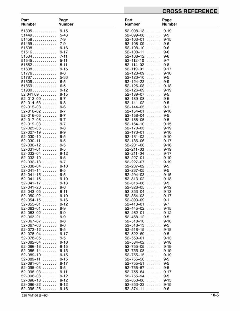
CROSS REFERENCE
10-5235 MM166 (8---95)
Part PageNumber Number
51395 9-15. . . . . . . . . . . .51449 5-43. . . . . . . . . . . .51458 7-9. . . . . . . . . . . .51459 7-9. . . . . . . . . . . .51508 9-16. . . . . . . . . . . .51516 9-17. . . . . . . . . . . .51534 7-11. . . . . . . . . . . .51545 5-11. . . . . . . . . . . .51562 5-11. . . . . . . . . . . .51638 9-15. . . . . . . . . . . .51776 9-6. . . . . . . . . . . .51787 5-33. . . . . . . . . . . .51805 6-5. . . . . . . . . . . .51869 6-5. . . . . . . . . . . .51980 9-12. . . . . . . . . . . .52 041 09 9-15. . . . . . . .52--012--09 9-7. . . . . . .52--014--63 9-8. . . . . . .52--015--08 9-6. . . . . . .52--016--02 9-7. . . . . . .52--016--05 9-7. . . . . . .52--017--08 9-7. . . . . . .52--019--03 9-7. . . . . . .52--025--36 9-8. . . . . . .52--027--19 9-9. . . . . . .52--030--10 9-5. . . . . . .52--030--11 9-5. . . . . . .52--030--12 9-5. . . . . . .52--031--01 9-5. . . . . . .52--032--04 9-12. . . . . . .52--032--10 9-5. . . . . . .52--032--13 9-7. . . . . . .52--038--04 9-10. . . . . . .52--041--14 9-5. . . . . . .52--041--15 9-5. . . . . . .52--041--16 9-10. . . . . . .52--041--17 9-13. . . . . . .52--041--20 9-6. . . . . . .52--043--05 9-11. . . . . . .52--050--02 9-10. . . . . . .52--054--15 9-16. . . . . . .52--055--01 9-12. . . . . . .52--063--01 9-9. . . . . . .52--063--02 9-9. . . . . . .52--063--21 9-9. . . . . . .52--067--67 9-6. . . . . . .52--067--68 9-6. . . . . . .52--072--12 9-5. . . . . . .52--078--04 9-17. . . . . . .52--078--05 9-5. . . . . . .52--082--04 9-16. . . . . . .52--086--13 9-15. . . . . . .52--086--14 9-15. . . . . . .52--089--10 9-15. . . . . . .52--089--11 9-15. . . . . . .52--091--04 9-17. . . . . . .52--095--03 9-5. . . . . . .52--096--03 9-11. . . . . . .52--096--08 9-12. . . . . . .52--096--18 9-12. . . . . . .52--096--22 9-12. . . . . . .52--096--26 9-16. . . . . . .
Part PageNumber Number
52--098--13 9-19. . . . . . .52--099--06 9-5. . . . . . .52--103--01 9-15. . . . . . .52--108--09 9-6. . . . . . .52--108--10 9-6. . . . . . .52--108--11 9-6. . . . . . .52--108--12 9-6. . . . . . .52--112--10 9-7. . . . . . .52--114--02 9-8. . . . . . .52--119--01 9-17. . . . . . .52--123--09 9-10. . . . . . .52--123--10 9-5. . . . . . .52--124--23 9-9. . . . . . .52--126--08 9-18. . . . . . .52--126--09 9-19. . . . . . .52--139--07 9-5. . . . . . .52--139--08 9-5. . . . . . .52--141--02 9-5. . . . . . .52--144--05 9-11. . . . . . .52--154--01 9-10. . . . . . .52--158--04 9-5. . . . . . .52--158--05 9-5. . . . . . .52--164--10 9-15. . . . . . .52--170--03 9-19. . . . . . .52--173--01 9-10. . . . . . .52--181--02 9-10. . . . . . .52--186--06 9-17. . . . . . .52--201--06 9-16. . . . . . .52--211--03 9-19. . . . . . .52--211--04 9-17. . . . . . .52--227--01 9-19. . . . . . .52--227--07 9-19. . . . . . .52--237--02 9-5. . . . . . .52--237--05 9-5. . . . . . .52--294--03 9-15. . . . . . .52--313--02 9-18. . . . . . .52--316--06 9-5. . . . . . .52--326--05 9-12. . . . . . .52--353--04 9-13. . . . . . .52--354--03 9-17. . . . . . .52--393--09 9-11. . . . . . .52--413--01 9-7. . . . . . .52--445--02 9-15. . . . . . .52--462--01 9-12. . . . . . .52--468--12 9-5. . . . . . .52--518--10 9-18. . . . . . .52--518--13 9-5. . . . . . .52--518--15 9-18. . . . . . .52--522--69 9-5. . . . . . .52--559--01 9-13. . . . . . .52--584--02 9-18. . . . . . .52--755--05 9-19. . . . . . .52--755--08 9-19. . . . . . .52--755--15 9-19. . . . . . .52--755--50 9-5. . . . . . .52--755--51 9-5. . . . . . .52--755--57 9-5. . . . . . .52--755--64 9-17. . . . . . .52--755--94 9-5. . . . . . .52--853--06 9-15. . . . . . .52--853--23 9-15. . . . . . .52--874--11 9-6. . . . . . .

CROSS REFERENCE
235 MM166 (8---95)10-6
Part PageNumber Number
52--874--12 9-6. . . . . . .52--874--13 9-6. . . . . . .52--874--14 9-6. . . . . . .52--874--15 9-6. . . . . . .52185 9-6. . . . . . . . . . . .52238 5-13. . . . . . . . . . . .52285 9-7. . . . . . . . . . . .52286 9-7. . . . . . . . . . . .52305 9-8. . . . . . . . . . . .52309 9-5. . . . . . . . . . . .52311 9-5. . . . . . . . . . . .52313 9-5. . . . . . . . . . . .52314 9-5. . . . . . . . . . . .52316 9-10. . . . . . . . . . . .52317 9-6. . . . . . . . . . . .52320 9-6. . . . . . . . . . . .52321 9-6. . . . . . . . . . . .52322 9-16. . . . . . . . . . . .52334 9-16. . . . . . . . . . . .52335 9-6. . . . . . . . . . . .52336 9-19. . . . . . . . . . . .52337 9-13. . . . . . . . . . . .52339 9-7. . . . . . . . . . . .52340 9-6. . . . . . . . . . . .52341 9-6. . . . . . . . . . . .52344 9-6. . . . . . . . . . . .52345 9-6. . . . . . . . . . . .52615 7-9. . . . . . . . . . . .52979 9-12, 9-17. . . . . . . . . . . .52984 9-16. . . . . . . . . . . .52989 9-13. . . . . . . . . . . .53020 9-17. . . . . . . . . . . .53268 6-5. . . . . . . . . . . .53395--2 6-5. . . . . . . . .53400--1 6-5. . . . . . . . .53400--4 6-5. . . . . . . . .54121 5-19. . . . . . . . . . . .54179 6-5. . . . . . . . . . . .54229--1 9-13. . . . . . . . .55248 7-7. . . . . . . . . . . .55264 7-6, 7-7. . . . . . . . . . . .55271 5-53. . . . . . . . . . . .55272 5-53. . . . . . . . . . . .55347 5-29. . . . . . . . . . . .55686 5-33, 5-37. . . . . . . . . . . .56692 5-35, 5-39. . . . . . . . . . . .56835 5-35. . . . . . . . . . . .57164 5-53. . . . . . . . . . . .57219 5-41. . . . . . . . . . . .57370 8-4. . . . . . . . . . . .57373 8-4. . . . . . . . . . . .57374 8-4. . . . . . . . . . . .57375 8-4. . . . . . . . . . . .57452 5-31. . . . . . . . . . . .57497 5-43. . . . . . . . . . . .57751 5-53, 7-13. . . . . . . . . . . .57772 5-9. . . . . . . . . . . .57778 5-51. . . . . . . . . . . .57803 5-53. . . . . . . . . . . .57804 6-6. . . . . . . . . . . .57807 5-53, 7-13. . . . . . . . . . . .57947 7-12. . . . . . . . . . . .
Part PageNumber Number
57965 5-41. . . . . . . . . . . .57967 7-12. . . . . . . . . . . .57984 5-31, 5-35, 5-37, 7-11. . . . . . . . . . . .58346 5-51. . . . . . . . . . . .58494 7-11. . . . . . . . . . . .58670 5-31. . . . . . . . . . . .58842 5-39. . . . . . . . . . . .61288 5-38. . . . . . . . . . . .61759 9-15. . . . . . . . . . . .61780 9-8. . . . . . . . . . . .61781 9-8. . . . . . . . . . . .61816 9-15. . . . . . . . . . . .61817 9-15. . . . . . . . . . . .61818 9-6. . . . . . . . . . . .61821 9-6. . . . . . . . . . . .62050 5-4, 5-49. . . . . . . . . . . .62170--2 5-9. . . . . . . . .62595--18 5-53. . . . . . . .62595--21 7-5. . . . . . . .63147 5-21. . . . . . . . . . . .63266A--2 5-51. . . . . . . .63416 5-37. . . . . . . . . . . .63475 5-37. . . . . . . . . . . .64141 5-53. . . . . . . . . . . .64379 5-21. . . . . . . . . . . .64595 7-11. . . . . . . . . . . .65223 5-33, 8-10. . . . . . . . . . . .65560 7-13. . . . . . . . . . . .65577 5-21. . . . . . . . . . . .65870--5 5-4. . . . . . . . .66099 7-9. . . . . . . . . . . .67718--2 5-4, 5-33. . . . . . . . .67718 5-33. . . . . . . . . . . .67767 6-5. . . . . . . . . . . .68198 5-4, 5-5. . . . . . . . . . . .68275 5-9. . . . . . . . . . . .68872 5-51. . . . . . . . . . . .68873 5-51. . . . . . . . . . . .69158 5-35. . . . . . . . . . . .69159 5-35. . . . . . . . . . . .69736 5-49. . . . . . . . . . . .70006 5-38. . . . . . . . . . . .75575 5-37. . . . . . . . . . . .76736 5-49. . . . . . . . . . . .77098 5-39. . . . . . . . . . . .77883 9-6. . . . . . . . . . . .82--755--07 9-17. . . . . . .82--755--09 9-7. . . . . . .82--755--11 9-7. . . . . . .82--755--13 9-7. . . . . . .82--755--16 9-5. . . . . . .82--755--17 9-5. . . . . . .82229 7-11. . . . . . . . . . . .82239 5-39. . . . . . . . . . . .82342 5-9. . . . . . . . . . . .82526 5-4, 5-49. . . . . . . . . . . .82621 7-11. . . . . . . . . . . .82709 5-51. . . . . . . . . . . .82784 5-38. . . . . . . . . . . .82802 5-33. . . . . . . . . . . .82809 5-41. . . . . . . . . . . .82816 5-41. . . . . . . . . . . .

CROSS REFERENCE
10-7235 MM166 (8---95)
Part PageNumber Number
82839 5-44. . . . . . . . . . . .82842 5-27. . . . . . . . . . . .86646 5-13, 5-35. . . . . . . . . . . .86922 5-11. . . . . . . . . . . .87021 5-53. . . . . . . . . . . .87027 5-27. . . . . . . . . . . .87030 5-27, 5-29. . . . . . . . . . . .87040 5-27. . . . . . . . . . . .87041 5-29. . . . . . . . . . . .87045 5-13. . . . . . . . . . . .87046 5-11. . . . . . . . . . . .87050 5-11. . . . . . . . . . . .87051 5-23. . . . . . . . . . . .87052 5-55. . . . . . . . . . . .87053 5-11. . . . . . . . . . . .87055 5-33, 8-8. . . . . . . . . . . .87056 5-15. . . . . . . . . . . .87059 5-17. . . . . . . . . . . .87060 5-4, 5-17. . . . . . . . . . . .87061 5-4, 5-17. . . . . . . . . . . .87068 6-5. . . . . . . . . . . .87074 5-19. . . . . . . . . . . .87078 5-27, 5-29. . . . . . . . . . . .87079 5-33. . . . . . . . . . . .87080 5-27, 5-29. . . . . . . . . . . .87082 5-29. . . . . . . . . . . .87083 7-8. . . . . . . . . . . .87084 5-19. . . . . . . . . . . .87088 5-29. . . . . . . . . . . .87097 5-5. . . . . . . . . . . .87099 5-5. . . . . . . . . . . .87103 5-17. . . . . . . . . . . .87104 5-21. . . . . . . . . . . .87108 5-21. . . . . . . . . . . .87109 5-43. . . . . . . . . . . .87113 5-15. . . . . . . . . . . .87114 5-15. . . . . . . . . . . .87117 5-17. . . . . . . . . . . .87120 5-21. . . . . . . . . . . .87131 5-44. . . . . . . . . . . .87134 5-11. . . . . . . . . . . .87142 5-11. . . . . . . . . . . .87146 5-13. . . . . . . . . . . .87147 5-13. . . . . . . . . . . .87148 5-13. . . . . . . . . . . .87149 5-13. . . . . . . . . . . .87150 9-9. . . . . . . . . . . .87152 5-21. . . . . . . . . . . .87155 5-44. . . . . . . . . . . .87156 8-11. . . . . . . . . . . .87162 5-21. . . . . . . . . . . .87164 5-4, 5-15. . . . . . . . . . . .87165 5-4, 5-15. . . . . . . . . . . .87166 5-15. . . . . . . . . . . .87167 5-4, 5-15. . . . . . . . . . . .87170 5-31. . . . . . . . . . . .87172 5-31. . . . . . . . . . . .87174 7-6, 7-7. . . . . . . . . . . .87175 5-5, 5-7. . . . . . . . . . . .87176 5-5, 5-7. . . . . . . . . . . .87179 5-47. . . . . . . . . . . .87180 5-4, 5-7. . . . . . . . . . . .
Part PageNumber Number
87181 5-4, 5-7. . . . . . . . . . . .87182 5-5, 5-7. . . . . . . . . . . .87183 5-5, 5-7. . . . . . . . . . . .87184 5-5, 5-7. . . . . . . . . . . .87189 5-7. . . . . . . . . . . .87190 5-7. . . . . . . . . . . .87195 5-11. . . . . . . . . . . .87197 5-4, 5-7. . . . . . . . . . . .87198 5-44. . . . . . . . . . . .87199 5-4, 5-7. . . . . . . . . . . .87201 5-17. . . . . . . . . . . .87202 5-15. . . . . . . . . . . .87203 5-15. . . . . . . . . . . .87206 5-4, 5-7. . . . . . . . . . . .87208 5-17. . . . . . . . . . . .87209 5-19. . . . . . . . . . . .87211 5-4, 5-7. . . . . . . . . . . .87215 5-27, 5-29. . . . . . . . . . . .87216 5-13. . . . . . . . . . . .87217 5-4, 5-15. . . . . . . . . . . .87218 5-37. . . . . . . . . . . .87221 5-31. . . . . . . . . . . .87222 5-35. . . . . . . . . . . .87226 9-5. . . . . . . . . . . .87228 5-13. . . . . . . . . . . .87229 5-13. . . . . . . . . . . .87236 5-35. . . . . . . . . . . .87242 5-31. . . . . . . . . . . .87244 5-13. . . . . . . . . . . .87245 5-43. . . . . . . . . . . .87246 5-37. . . . . . . . . . . .87248 5-11. . . . . . . . . . . .87250 5-53. . . . . . . . . . . .87251 5-25. . . . . . . . . . . .87253 5-11. . . . . . . . . . . .87254 5-44. . . . . . . . . . . .87257 5-43. . . . . . . . . . . .87265 5-23. . . . . . . . . . . .87266 8-7. . . . . . . . . . . .87267 5-27. . . . . . . . . . . .87270 5-11. . . . . . . . . . . .87275 5-29. . . . . . . . . . . .87280 5-23. . . . . . . . . . . .87283 5-53. . . . . . . . . . . .87286 5-19. . . . . . . . . . . .87293 5-31. . . . . . . . . . . .87297 5-31. . . . . . . . . . . .87298 5-31. . . . . . . . . . . .87299 5-25. . . . . . . . . . . .87306 5-19. . . . . . . . . . . .87309 6-5. . . . . . . . . . . .87313 9-15. . . . . . . . . . . .87314 9-15. . . . . . . . . . . .87315 9-15. . . . . . . . . . . .87322 9-15. . . . . . . . . . . .87333 5-5. . . . . . . . . . . .87334 5-5. . . . . . . . . . . .87337 5-18. . . . . . . . . . . .87338 5-4, 5-18. . . . . . . . . . . .87341 5-19. . . . . . . . . . . .87343 6-6. . . . . . . . . . . .87345 5-55. . . . . . . . . . . .

CROSS REFERENCE
235 MM166 (8---95)10-8
Part PageNumber Number
87346 5-9. . . . . . . . . . . .87351 5-35. . . . . . . . . . . .87353 5-5, 5-7. . . . . . . . . . . .87354 5-5, 5-7. . . . . . . . . . . .87356 5-56. . . . . . . . . . . .87360 5-35. . . . . . . . . . . .87362 5-35. . . . . . . . . . . .87365 5-35. . . . . . . . . . . .87368 5-27, 5-29. . . . . . . . . . . .87369 5-53. . . . . . . . . . . .87370 5-35. . . . . . . . . . . .87375 5-37. . . . . . . . . . . .87376 5-37. . . . . . . . . . . .87390 5-15. . . . . . . . . . . .87392 5-38. . . . . . . . . . . .87394 5-49. . . . . . . . . . . .87396 5-49. . . . . . . . . . . .87404 5-37. . . . . . . . . . . .87405 5-4, 5-15. . . . . . . . . . . .87406 5-17. . . . . . . . . . . .87407 5-9. . . . . . . . . . . .87408 5-9. . . . . . . . . . . .87409 5-37, 8-6. . . . . . . . . . . .87411 5-39. . . . . . . . . . . .87412 5-4, 5-21. . . . . . . . . . . .87413 5-4, 5-21. . . . . . . . . . . .87414 5-33. . . . . . . . . . . .87417 5-39, 8-4. . . . . . . . . . . .87418 5-31, 7-11. . . . . . . . . . . .87419 5-5. . . . . . . . . . . .87420 5-5. . . . . . . . . . . .87421 5-39. . . . . . . . . . . .87430 5-18. . . . . . . . . . . .87432 7-8. . . . . . . . . . . .87433 5-13. . . . . . . . . . . .87435 5-47. . . . . . . . . . . .87439 5-31, 7-11. . . . . . . . . . . .87444 5-21, 7-11. . . . . . . . . . . .87450 7-5. . . . . . . . . . . .87451 5-35, 8-11. . . . . . . . . . . .87458 5-39. . . . . . . . . . . .87460 5-18. . . . . . . . . . . .87461 5-17. . . . . . . . . . . .87462 7-8. . . . . . . . . . . .87464 5-4, 5-7. . . . . . . . . . . .87465 5-4, 5-7. . . . . . . . . . . .87474 5-27, 5-35. . . . . . . . . . . .87475 5-31, 8-5. . . . . . . . . . . .87481 5-9. . . . . . . . . . . .87484 5-38. . . . . . . . . . . .87488 5-43. . . . . . . . . . . .87491 5-45. . . . . . . . . . . .87500 5-7. . . . . . . . . . . .87502 5-47. . . . . . . . . . . .87503 6-5. . . . . . . . . . . .87511 5-35. . . . . . . . . . . .87512 5-35. . . . . . . . . . . .87513 5-35. . . . . . . . . . . .87521 5-35. . . . . . . . . . . .87534 5-47. . . . . . . . . . . .87543 5-35. . . . . . . . . . . .87544 5-47. . . . . . . . . . . .
Part PageNumber Number
87546 5-19. . . . . . . . . . . .87550 5-19. . . . . . . . . . . .87552 5-55. . . . . . . . . . . .87555 5-5, 5-7. . . . . . . . . . . .87573 5-23. . . . . . . . . . . .87574 5-31. . . . . . . . . . . .87579 5-15. . . . . . . . . . . .87580 5-23. . . . . . . . . . . .87581 5-9. . . . . . . . . . . .87585 5-23. . . . . . . . . . . .87586 5-4, 5-7. . . . . . . . . . . .87593 5-47. . . . . . . . . . . .87603 5-55. . . . . . . . . . . .87612 5-9. . . . . . . . . . . .87620 5-25. . . . . . . . . . . .87621 5-18. . . . . . . . . . . .87627 5-31. . . . . . . . . . . .87630 5-25. . . . . . . . . . . .87631 5-27, 5-29. . . . . . . . . . . .87637 5-53, 6-6. . . . . . . . . . . .87639 5-56. . . . . . . . . . . .87640 5-56. . . . . . . . . . . .87645 5-27. . . . . . . . . . . .87646 5-27. . . . . . . . . . . .87649 7-6, 7-7. . . . . . . . . . . .87650 5-55. . . . . . . . . . . .87651 5-41. . . . . . . . . . . .87652 5-41. . . . . . . . . . . .87655 7-4. . . . . . . . . . . .87656 5-31. . . . . . . . . . . .87657 7-4. . . . . . . . . . . .87662 8-5, 8-12. . . . . . . . . . . .87663 8-5. . . . . . . . . . . .87665 5-47. . . . . . . . . . . .87672 5-41. . . . . . . . . . . .87673 7-6. . . . . . . . . . . .87674 5-39. . . . . . . . . . . .87675 5-39. . . . . . . . . . . .87676 5-39. . . . . . . . . . . .87677 7-11. . . . . . . . . . . .87678 5-41. . . . . . . . . . . .87680 5-41. . . . . . . . . . . .87687 5-4, 5-21. . . . . . . . . . . .87688 5-4, 5-21. . . . . . . . . . . .87689 5-4, 5-21. . . . . . . . . . . .87692 5-47. . . . . . . . . . . .87693 5-21. . . . . . . . . . . .87694 7-4. . . . . . . . . . . .87695 7-4. . . . . . . . . . . .87697 7-4. . . . . . . . . . . .87698 7-4. . . . . . . . . . . .87701 7-4. . . . . . . . . . . .87705 5-9. . . . . . . . . . . .87707 5-23. . . . . . . . . . . .87731 5-5, 5-7. . . . . . . . . . . .87732 5-35. . . . . . . . . . . .87734 5-35, 8-7. . . . . . . . . . . .87735 5-35. . . . . . . . . . . .87736 5-47. . . . . . . . . . . .87739 5-18. . . . . . . . . . . .87740 5-49. . . . . . . . . . . .87742 7-5. . . . . . . . . . . .

CROSS REFERENCE
10-9235 MM166 (8---95)
Part PageNumber Number
87744 8-8. . . . . . . . . . . .87754 8-6. . . . . . . . . . . .87758 6-5. . . . . . . . . . . .87764 5-49. . . . . . . . . . . .87773 6-5. . . . . . . . . . . .87776 6-5. . . . . . . . . . . .87778 5-47. . . . . . . . . . . .87780 5-51. . . . . . . . . . . .87781 5-51. . . . . . . . . . . .87784 8-4. . . . . . . . . . . .87785 8-4. . . . . . . . . . . .87787 6-5. . . . . . . . . . . .87788 6-5. . . . . . . . . . . .87789 7-6, 7-7. . . . . . . . . . . .87790 7-8. . . . . . . . . . . .87791 7-7. . . . . . . . . . . .87792 7-6. . . . . . . . . . . .87797 5-45. . . . . . . . . . . .87798 5-45. . . . . . . . . . . .87803 5-45. . . . . . . . . . . .87804 5-45. . . . . . . . . . . .87812 6-5. . . . . . . . . . . .87820 5-43. . . . . . . . . . . .87829 7-5. . . . . . . . . . . .87832 5-25. . . . . . . . . . . .87833 6-5. . . . . . . . . . . .87835 6-5. . . . . . . . . . . .87837 6-5. . . . . . . . . . . .87850 8-8, 8-9, 8-10. . . . . . . . . . . .87851 8-8, 8-9, 8-10. . . . . . . . . . . .87853 5-25. . . . . . . . . . . .87854 5-13. . . . . . . . . . . .87860 5-25. . . . . . . . . . . .87865 5-53. . . . . . . . . . . .87868 5-11. . . . . . . . . . . .87869 5-11. . . . . . . . . . . .87871 5-4, 9-18. . . . . . . . . . . .87872 5-4, 9-16. . . . . . . . . . . .87873 5-4, 9-16. . . . . . . . . . . .87874 5-4, 9-10. . . . . . . . . . . .87876 5-47. . . . . . . . . . . .87881 5-44. . . . . . . . . . . .87883 6-5. . . . . . . . . . . .87888 9-5. . . . . . . . . . . .87889 9-5. . . . . . . . . . . .87890 9-5. . . . . . . . . . . .87891 9-5. . . . . . . . . . . .87892 9-5. . . . . . . . . . . .87893 9-5. . . . . . . . . . . .87894 9-5. . . . . . . . . . . .87895 9-5. . . . . . . . . . . .87896 9-5. . . . . . . . . . . .87897 9-10. . . . . . . . . . . .87898 5-4, 9-12. . . . . . . . . . . .87899 5-4, 9-12. . . . . . . . . . . .87900 9-13. . . . . . . . . . . .87901 9-15. . . . . . . . . . . .87902 9-15. . . . . . . . . . . .87903 9-15. . . . . . . . . . . .87904 9-15. . . . . . . . . . . .87905 9-16. . . . . . . . . . . .87906 9-16. . . . . . . . . . . .
Part PageNumber Number
87907 9-17. . . . . . . . . . . .87908 9-17. . . . . . . . . . . .87909 9-17. . . . . . . . . . . .87910 9-17. . . . . . . . . . . .87911 9-17. . . . . . . . . . . .87912 9-17. . . . . . . . . . . .87913 9-18. . . . . . . . . . . .87914 9-18. . . . . . . . . . . .87915 5-4, 9-18. . . . . . . . . . . .87916 9-18. . . . . . . . . . . .87917 9-19. . . . . . . . . . . .87918 9-19. . . . . . . . . . . .87920 5-4, 9-12. . . . . . . . . . . .87921 9-16. . . . . . . . . . . .87922 9-17. . . . . . . . . . . .87924 9-5. . . . . . . . . . . .87948 5-9. . . . . . . . . . . .87949 5-9. . . . . . . . . . . .87950 5-31. . . . . . . . . . . .87954 5-56. . . . . . . . . . . .87955 5-56. . . . . . . . . . . .87958 5-15, 5-17. . . . . . . . . . . .87961 5-4. . . . . . . . . . . .87962 5-4. . . . . . . . . . . .87963 5-4. . . . . . . . . . . .87964 5-4. . . . . . . . . . . .87965 5-4. . . . . . . . . . . .87966 5-11. . . . . . . . . . . .87967 5-19. . . . . . . . . . . .87968 5-19. . . . . . . . . . . .87969 5-17. . . . . . . . . . . .87970 5-7. . . . . . . . . . . .87975 5-5, 5-7. . . . . . . . . . . .87977 5-53. . . . . . . . . . . .87979 5-17. . . . . . . . . . . .87982 5-19. . . . . . . . . . . .87983 5-23. . . . . . . . . . . .87985 5-19. . . . . . . . . . . .

CROSS REFERENCE
235 MM166 (8---95)10-10
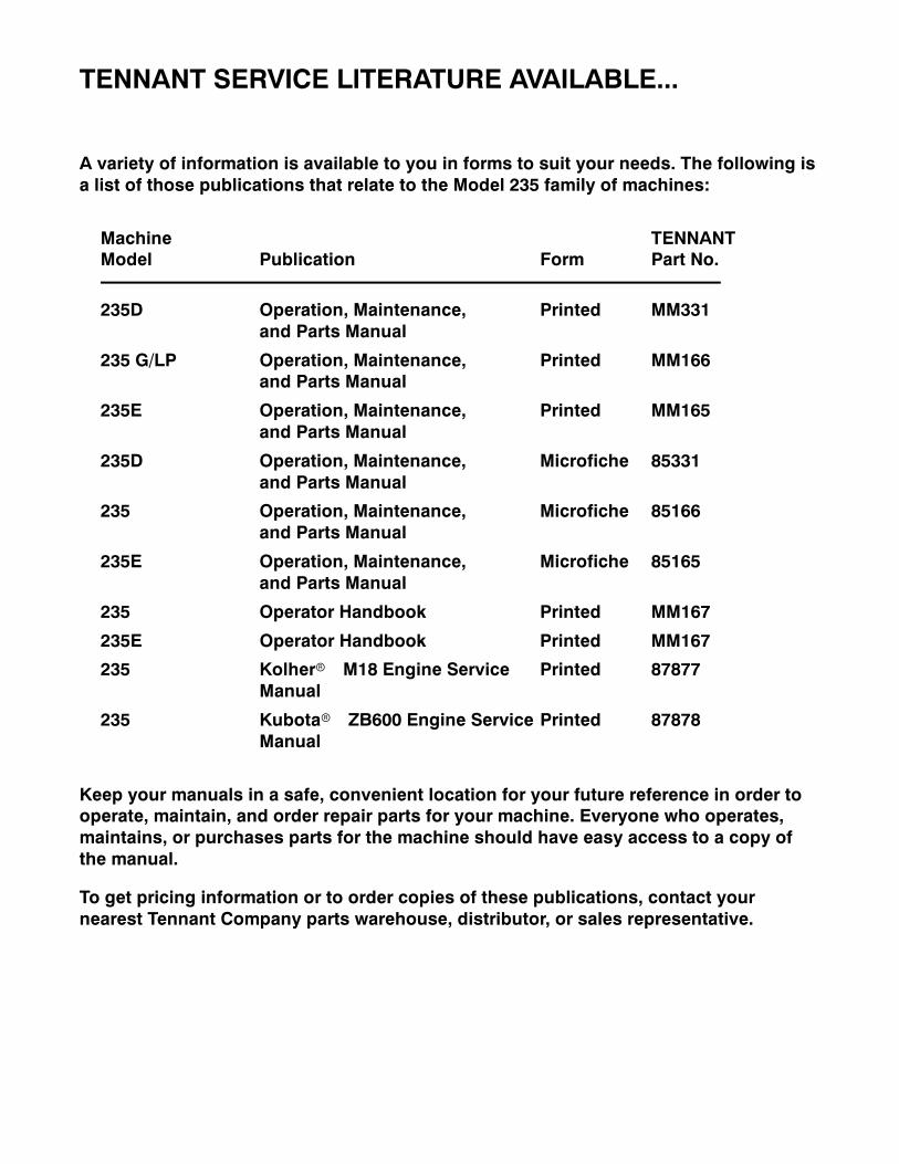
TENNANT SERVICE LITERATURE AVAILABLE...
A variety of information is available to you in forms to suit your needs. The following isa list of those publications that relate to the Model 235 family of machines:
Machine TENNANTModel Publication Form Part No.
235D Operation, Maintenance, Printed MM331and Parts Manual
235 G/LP Operation, Maintenance, Printed MM166and Parts Manual
235E Operation, Maintenance, Printed MM165and Parts Manual
235D Operation, Maintenance, Microfiche 85331and Parts Manual
235 Operation, Maintenance, Microfiche 85166and Parts Manual
235E Operation, Maintenance, Microfiche 85165and Parts Manual
235 Operator Handbook Printed MM167
235E Operator Handbook Printed MM167
235 Kolherr M18 Engine Service Printed 87877Manual
235 Kubotar ZB600 Engine Service Printed 87878Manual
Keep your manuals in a safe, convenient location for your future reference in order tooperate, maintain, and order repair parts for your machine. Everyone who operates,maintains, or purchases parts for the machine should have easy access to a copy ofthe manual.
To get pricing information or to order copies of these publications, contact yournearest Tennant Company parts warehouse, distributor, or sales representative.


