10.1 Rev. 2-06 ❏ TRIPLE O-RING SEALS PLUS DIRT SEAL – two above thrust collar and one below, retain lubricant in this criti- cal area. Top two are replaceable with valve fully open and under pressure. Fourth seal at top serves as dirt seal†. ❏ TWO ANTI-FRICTION WASHERS WITH LUBRICATION – made of polymer, one above and one below the thrust collar, reduce operating torque to open or close valve. ❏ STEM – forged manganese bronze bar stock is upset, then machined to form a thrust collar for superior strength in this critical area. ❏ WEDGE – cast iron, fully encapsu- lated in molded rubber - no exposed iron. ❏ EXTENDED WEDGE GUIDES – molded as part of wedge, ride inside body channels to maintain wedge alignment throughout its travel. ❏ GUIDE CAP BEARINGS – made of polymer and snapped over rubber covered wedge guides, provide bearing surfaces that protect both wedge and interior body coating from wear and aid in easy operation – even the largest valves installed horizontally. Rollers, tracks or scrapers are not needed. ❏ SMOOTH, OVERSIZED FLOW WAY – full, round, unobstructed flow way accommodates full size cutters, provides superior flow characteristics and reduces pumping costs.** ❏ MUELLER ® PRO-GARD ™ FUSION EPOXY COATING – 10 mils* thick protects all inside and outside iron sur- faces, and complies with AWWA C550 and certified to ANSI/NSF 61. ❏ 250 PSIG MAXIMUM WORKING PRESSURE – Hydrostatically tested at 500 psig. Surpasses ANSI/AWWA Standard C509 by 25%. UL/FM: 200 psig MWP.*** ❏ AMERICAN MADE QUALITY – factory in Chattanooga, TN with ISO 9001:2000 certification, and UL 262, FM 1120/1130. Certified to ANSI/NSF 61. Manufactured and tested in compli- ance with ANSI/AWWA Standard C509. UL Listed and FM Approved. ❏ BI-DIRECTIONAL FLOW ❏ FLAT BOTTOM SURFACES – stands upright for easier handling and storage. ❏ 10-YEAR LIMITED WARRANTY – assured reliability (see separate Mueller Warranty document for terms). MUELLER ® 2360 SERIES™ RESILIENT WEDGE GATE VALVE MUELLER ® 2300 Series Resilient Wedge Gate Valves Mueller ® Resilient Wedge Gate Valves have features to make them easier to operate and to preserve the sealing capability and interior coating integrity for many years of reliable service. In addition to popular end connection options, Mueller brand RW valves can be ordered with Mueller’s exclusive Aqua-Grip ™ System that incorporates an O-ring sealed compression connection and integral pipe restraint in one “ready to use” easy and quick to install package. Mueller 2" – 12" 2360 Series Resilient Wedge Gate Valve Features Mueller 14" – 48" 2361 Series Resilient Wedge Gate Valve Features In addition to all the features of the smaller 2360 series valves, large size Mueller 2361 series RW valves offer these features: ❏ STEM – Manganese bronze casting with integral thrust collar. ❏ WEDGE – Ductile iron, fully encapsulated in molded rubber. ❏ BODY AND BONNET – Ductile iron. ❏ COMPLIANCE – In addition to those above: ANSI/AWWA Standard C515. ❏ MAXIMUM WORKING PRESSURE – 14"-48" AWWA valves rated at 250 psig – tested at 500 psig. UL/FM valves 200 psig MWP (14"-16" 250 psig MWP).*** Double-Disc Style gate valves follow the RW valve pages. *Nominal **16" valve requires 1/2" undersized cutter. ***250 psi UL/FM rating available as an option. †Dirt seal on 4"-12" valves.
Transcript
10.1Rev. 2-06
❏ TRIPLE O-RING SEALS PLUS DIRT SEAL – two above thrust collar and one below, retain lubricant in this criti-cal area. Top two are replaceable with valve fully open and under pressure. Fourth seal at top serves as dirt seal†.
❏ TWO ANTI-FRICTION WASHERS WITH LUBRICATION – made of polymer, one above and one below the thrust collar, reduce operating torque to open or close valve.
❏ STEM – forged manganese bronze bar stock is upset, then machined to form a thrust collar for superior strength in this critical area.
❏ WEDGE – cast iron, fully encapsu-lated in molded rubber - no exposed iron.
❏ EXTENDED WEDGE GUIDES – molded as part of wedge, ride inside body channels to maintain wedge alignment throughout its travel.
❏ GUIDE CAP BEARINGS – made of polymer and snapped over rubber covered wedge guides, provide bearing surfaces that protect both wedge and interior body coating from wear and aid in easy operation – even the largest valves installed horizontally. Rollers, tracks or scrapers are not needed.
❏ SMOOTH, OVERSIZED FLOW WAY – full, round, unobstructed flow way accommodates full size cutters, provides superior flow characteristics and reduces pumping costs.**
❏ MUELLER® PRO-GARD™ FUSION EPOXY COATING – 10 mils* thick protects all inside and outside iron sur-faces, and complies with AWWA C550 and certified to ANSI/NSF 61.
❏ 250 PSIG MAXIMUM WORKING PRESSURE – Hydrostatically tested at 500 psig. Surpasses ANSI/AWWA Standard C509 by 25%. UL/FM: 200 psig MWP.***
❏ AMERICAN MADE QUALITY – factory in Chattanooga, TN with ISO 9001:2000 certification, and UL 262, FM 1120/1130. Certified to ANSI/NSF 61. Manufactured and tested in compli-ance with ANSI/AWWA Standard C509. UL Listed and FM Approved.
❏ BI-DIRECTIONAL FLOW
❏ FLAT BOTTOM SURFACES – stands upright for easier handling and storage.
❏ 10-YEAR LIMITED WARRANTY – assured reliability (see separate Mueller Warranty document for terms).
MUELLER® 2360 SERIES™RESILIENT WEDGE GATE VALVE
MUELLER® 2300 Series Resilient Wedge Gate Valves Mueller® Resilient Wedge Gate Valves have features to make them easier to operate and to preserve the sealing capability and interior coating integrity for many years of reliable service. In addition to popular end connection options, Mueller brand RW valves can be ordered with Mueller’s exclusive Aqua-Grip™ System that incorporates an O-ring sealed compression connection and integral pipe restraint in one “ready to use” easy and quick to install package.
Mueller 2" – 12" 2360 Series Resilient Wedge Gate Valve Features
Mueller 14" – 48" 2361 Series Resilient Wedge Gate Valve FeaturesIn addition to all the features of the smaller 2360 series valves, large size Mueller 2361 series RW valves offer these features:
❏ STEM – Manganese bronze casting with integral thrust collar.
❏ WEDGE – Ductile iron, fully encapsulated in molded rubber.
❏ BODY AND BONNET – Ductile iron.
❏ COMPLIANCE – In addition to those above: ANSI/AWWA Standard C515.
❏ MAXIMUM WORKING PRESSURE – 14"-48" AWWA valves rated at 250 psig – tested at 500 psig. UL/FM valves 200 psig MWP (14"-16" 250 psig MWP).***
Double-Disc Style gate valves follow the RW valve pages.
*Nominal**16" valve requires 1/2" undersized cutter.***250 psi UL/FM rating available as an option. †Dirt seal on 4"-12" valves.
10.44Rev. 2-06
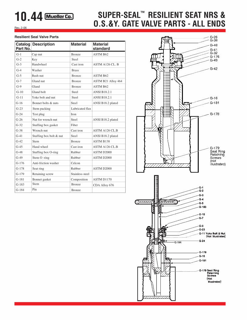
SUPER-SEAL™ RESILIENT SEAT NRS &O.S.&Y. GATE VALVE PARTS - ALL ENDS
GATE VALVEORDERING INSTRUCTIONSTo order Gate Valves specify:
Quantity If more than one size, specify quantity of each
Size Nominal size of valve
Catalog number
Special catalog number suffix See chart at bottom of page 10.40 if gearing, grease cases, bypass valves or position indicators are required. The appropriate suffix number is added to the base catalog number.
Direction of opening Specify open left (counter-clockwise) or open right (clockwise). Wrench nuts on valves that open to the right are painted red for identi-fication purposes.
Method of operation N.R.S. valves are available with either a 2" square wrench nut or a handwheel. Handwheels are standard on flanged x flanged and thread x thread valves; all other NRS* valves have a 2" square wrench nut as standard. Outside screw and yoke type valves are available with handwheel only. When ordering NRS valves, specify wrench nut or handwheel.
* 30"-48" resilient wedge and double-disc gate valves must be ordered with actuator.
Special Requirements Contact MUELLER Customer Service Center with special require-ments such as special paints or coatings, low zinc bronze stems, stain-less steel fasteners etc.
Gate Valve Repair Parts To order repair parts specify size of valve, direction of opening, year date on body, part number, catalog number of valve if known, and type of ends if ordering body.
10.42Rev. 2-06
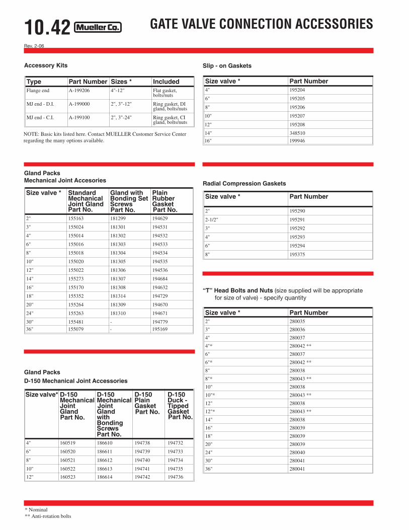
GATE VALVE CONNECTION ACCESSORIES
“T” Head Bolts and Nuts (size supplied will be appropriate for size of valve) - specify quantity
Type Part Number Sizes * IncludedFlange end A-199206 4"-12" Flat gasket,
bolts/nuts
MJ end - D.I. A-199000 2", 3"-12" Ring gasket, DIgland, bolts/nuts
MJ end - C.I. A-199100 2", 3"-24" Ring gasket, CIgland, bolts/nuts
Rollers, Tracks and Scrapers (Double-disc gate valves only) Double-disc gate valves in sizes 16" through 36" for vertical installa-tions are furnished with a shoe on each side of the disc assembly for guiding the disc assembly throughout its entire travel. Gate valves in sizes 16" through 36" for horizontal installations are furnished with rollers which travel on a bronze track in the body and bonnet. These rollers support the weight of the disc assembly throughout its entire travel. The roller carriage has scrapers for cleaning the track ahead of the rollers. Rollers and tracks are required on 16" and larger double-disc gate valves when the main valve stem is horizontal. They are not required on bevel geared valves specified for vertical installation.
Valve size Conversion kit partnumber
2" 181338
3" 181393*
4" 181340
6" 181341
8" 181342
10" 181343
12" 181344
14" 181388
16" 181389
18" 181390
20" 181391
24" 181392
*1956 Design. For valves made prior to 1956 use kit number 181339
O-ring conversion kit contains the following
❏ (1) G-70 Stuffing box
❏ (2) G-48 O-rings
❏ (1) G-32 Stuffing box gasket
❏ G-41 bolts and nuts
(2) for 2" valve
(4) for 3"-14" valves
(6) for 16"-24" valves
Double disc gate valve o-ring conversion kit
MUELLER CO. offers kits to convert non-rising stem conven-tionally packed gate valves to O-ring sealed type. The conver-sion replaces the conventional packing with two O-ring seals above the thrust collar and a gasket seal between the bonnet and new stuffing box.
10.40Rev. 9-09 Shaded area indicates change.
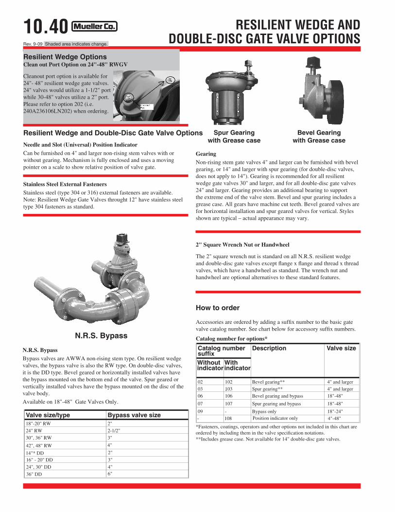
RESILIENT WEDGE AND DOUBLE-DISC GATE VALVE OPTIONS
Catalog numbersuffix
Description Valve size
Withoutindicator
Withindicator
02 102 Bevel gearing** 4" and larger
03 103 Spur gearing** 4" and larger
06 106 Bevel gearing and bypass 18"-48"
07 107 Spur gearing and bypass 18"-48"
09 - Bypass only 18"-24"
-
- 108 Position indicator only 4"-48"Valve size/type Bypass valve size18"-20" RW 2"
24" RW 2-1/2"
30", 36" RW 3"
42", 48" RW 4"
14"* DD 2"
16" - 20" DD 3"
24", 30" DD 4"
36" DD 6"
*Fasteners, coatings, operators and other options not included in this chart are ordered by including them in the valve specification notations. **Includes grease case. Not available for 14" double-disc gate valves.
Accessories are ordered by adding a suffix number to the basic gate valve catalog number. See chart below for accessory suffix numbers.
Catalog number for options*
Stainless Steel External Fasteners Stainless steel (type 304 or 316) external fasteners are available. Note: Resilient Wedge Gate Valves throught 12" have stainless steel type 304 fasteners as standard.
Resilient Wedge and Double-Disc Gate Valve Options
Needle and Slot (Universal) Position Indicator Can be furnished on 4" and larger non-rising stem valves with or without gearing. Mechanism is fully enclosed and uses a moving pointer on a scale to show relative position of valve gate.
N.R.S. Bypass Bypass valves are AWWA non-rising stem type. On resilient wedge valves, the bypass valve is also the RW type. On double-disc valves, it is the DD type. Bevel geared or horizontally installed valves have the bypass mounted on the bottom end of the valve. Spur geared or vertically installed valves have the bypass mounted on the disc of the valve body.
Available on 18"-48" Gate Valves Only.
N.R.S. Bypass
Gearing Non-rising stem gate valves 4" and larger can be furnished with bevel gearing, or 14" and larger with spur gearing (for double-disc valves, does not apply to 14"). Gearing is recommended for all resilient wedge gate valves 30" and larger, and for all double-disc gate valves 24" and larger. Gearing provides an additional bearing to support the extreme end of the valve stem. Bevel and spur gearing includes a grease case. All gears have machine cut teeth. Bevel geared valves are for horizontal installation and spur geared valves for vertical. Styles shown are typical – actual appearance may vary.
Bevel Gearing with Grease case
Spur Gearingwith Grease case
2" Square Wrench Nut or Handwheel
The 2" square wrench nut is standard on all N.R.S. resilient wedge and double-disc gate valves except flange x flange and thread x thread valves, which have a handwheel as standard. The wrench nut and handwheel are optional alternatives to these standard features.
How to order
Resilient Wedge Options Clean out Port Option on 24"-48" RWGV
Cleanout port option is available for 24"- 48" resilient wedge gate valves. 24" valves would utilize a 1-1/2" port while 30-48" valves utilize a 2” port. Please refer to option 202 (i.e. 240A236106LN202) when ordering.
10.39Rev. 2-06
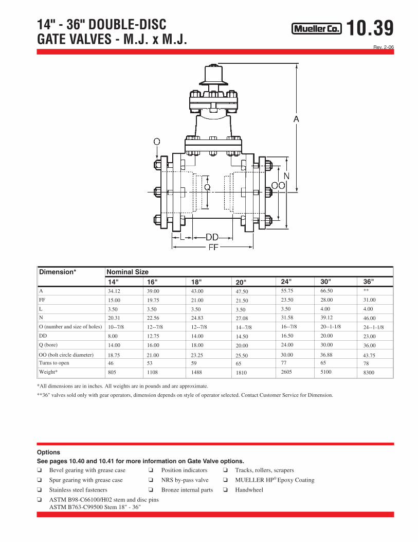
14" - 36" DOUBLE-DISC GATE VALVES - M.J. x M.J.
OptionsSee pages 10.40 and 10.41 for more information on Gate Valve options. ❏ Bevel gearing with grease case ❏ Position indicators ❏ Tracks, rollers, scrapers
❏ Spur gearing with grease case ❏ NRS by-pass valve ❏ MUELLER HP® Epoxy Coating
❏ Stainless steel fasteners ❏ Bronze internal parts ❏ Handwheel
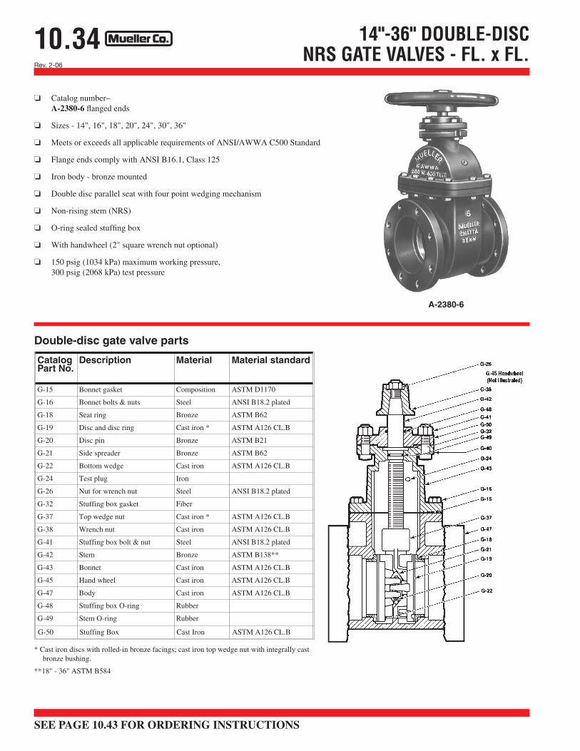
❏ Catalog number–A-2380-20 standard mechanical joint ends (with accessories unassembled)A-2380-22 standard mechanical joint ends (with accessories and bonding set screws in glands unassembled) A-2380-23 standard mechanical joint ends (less accessories)
❏ Sizes - 14", 16", 18", 20", 24", 30", 36"
❏ Meets or exceeds all applicable requirements of ANSI/AWWA C500 Standard
❏ Mechanical joint ends comply with ANSI/AWWA C111 Standard
❏ Iron body - bronze mounted
❏ Double disc parallel seat with four point wedging mechanism
❏ Non-rising stem (NRS)
❏ O-ring sealed stuffing box
❏ 2" square wrench nut (handwheel optional)
❏ 30" & 36" sizes – 150 psig (1034 kPa) maximum working pressure,300 psig (2068 kPa) test pressure
** Cast iron discs with rolled-in bronze facings; cast iron top wedge nut with integrally cast bronze bushing.
***18" - 36" ASTM B583
A-2380-20
10.37Rev. 2-06
30" & 36" DOUBLE-DISC GATE VALVES - FL. x M.J.
OptionsSee pages 10.40 and 10.41 for more information on Gate Valve options. ❏ Bevel gearing with grease case ❏ Position indicators ❏ Tracks, rollers, scrapers
❏ Spur gearing with grease case ❏ NRS by-pass valve ❏ MUELLER HP® Epoxy Coating
❏ Stainless steel fasteners ❏ Bronze internal parts ❏ Handwheel
❏ Catalog number–A-2380-16 flanged x mechanical joint (with accessories unassembled) A-2380-18 flanged x mechanical joint (accessories and bonding set screws in gland unassembled)A-2380-19 flanged x mechanical joint (less accessories)
❏ Sizes - 30" & 36"
❏ Meets or exceeds all applicable requirements of ANSI/AWWA C500 Standard
❏ Flange ends comply with ANSI B16.1, Class 125
❏ Mechanical joint ends comply with ANSI/AWWA C111 Standard
❏ Iron body - bronze mounted
❏ Double disc parallel seat with four point wedging mechanism
❏ Non-rising stem (NRS)
❏ O-ring sealed stuffing box
❏ 2" square wrench nut (handwheel optional)
❏ 150 psig (1034 kPa) maximum working pressure,300 psig (2068 kPa) test pressure
** Cast iron discs with rolled-in bronze facings; cast iron top wedge nut with integrally cast bronze bushing.
***18" - 36" ASTM B583
A-2380-16
SEE PAGE 10.43 FOR ORDERING INSTRUCTIONS
10.35Rev. 2-06
OptionsSee pages 10.40 and 10.41 for more information on Gate Valve options. ❏ Bevel gearing with grease case ❏ NRS by-pass valve
❏ Spur gearing with grease case ❏ 2" Square wrench nut
G-204 Hand Wheel (not shown) Cast Iron ASTM A126 CL.B
G-205 Stem Nut Bronze ASTM B62
G-206 Guide Cap Bearings Celcon
G-207 Stuffing Box Ductile Iron ASTM A536
G-208 Anti-friction Washers (2) Brass
G-209 Wedge,Rubber Encapsulation
Ductile Iron*SBR
ASTM A536--
G-210 Bonnet Ductile Iron ASTM A536
G-211 Bonnet O-ring RubberG-212 Body Ductile Iron ASTM A536
G-202
G-200
G-207
G-41
G-201
G-208
G-49
G-203
G-210
G-16
G-211
G-205
G-209
G-206
G-212
* Fully encapsulated in molded rubber with no iron exposed
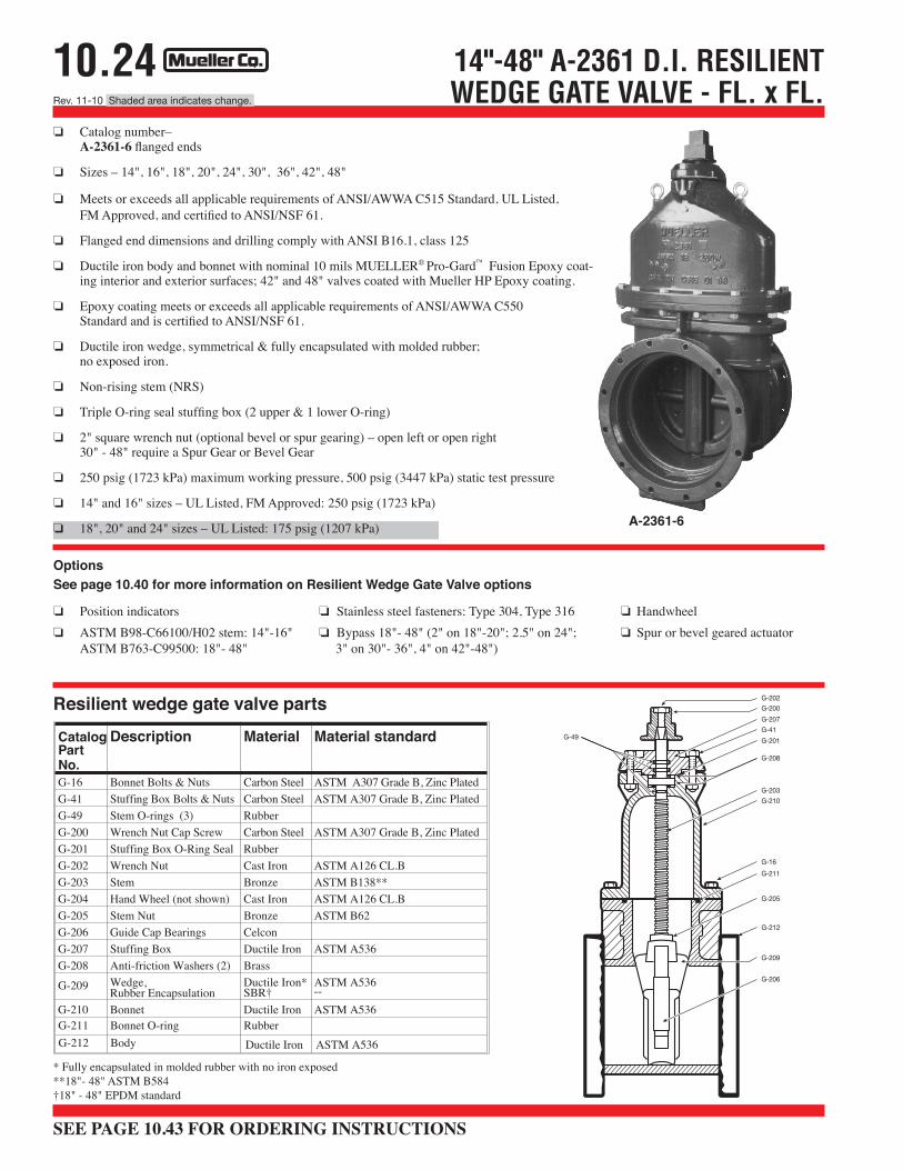
Options See page 10.40 for more information on Resilient Wedge Gate Valve options
❏ Position indicators ❏ Stainless steel fasteners: Type 304, Type 316 ❏ Spur or bevel geared actuator
❏ ASTM B98-C66100/H02 stem ❏ Handwheel
A-2361-40
SEE PAGE 10.43 FOR ORDERING INSTRUCTIONS
10.29Rev. 5-11 Shaded area indicates change.
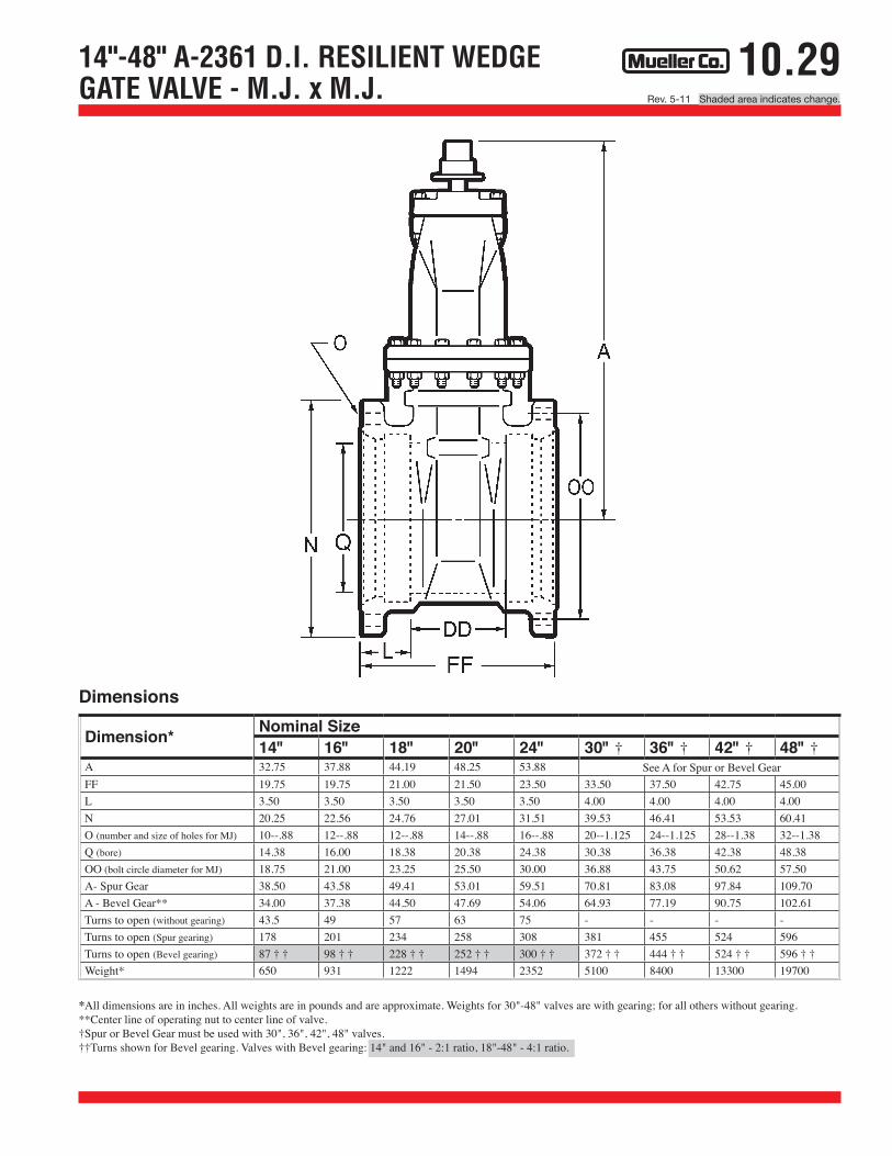
14"-48" A-2361 D.I. RESILIENT WEDGEGATE VALVE - M.J. x M.J.
*All dimensions are in inches. All weights are in pounds and are approximate. Weights for 30"-48" valves are with gearing; for all others without gearing. **Center line of operating nut to center line of valve. †Spur or Bevel Gear must be used with 30", 36", 42", 48" valves. ††Turns shown for Bevel gearing. Valves with Bevel gearing: 14" and 16" - 2:1 ratio, 18"-48" - 4:1 ratio.
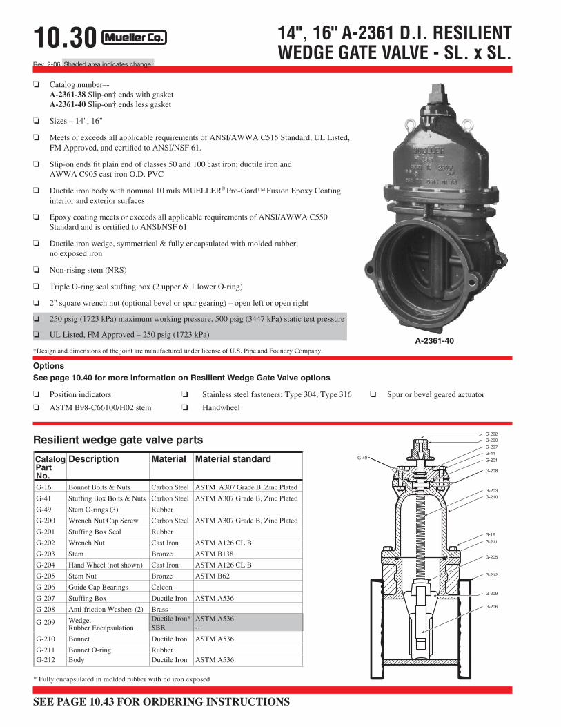
❏ Meets or exceeds all applicable requirements of ANSI/AWWA C515 Standard, UL Listed, FM Approved, and certified to ANSI/NSF 61.
❏ Mechanical joint end complies with ANSI/AWWA C111 Standard.
❏ Ductile Iron body and bonnet with nominal 10 mils MUELLER® Pro-Gard™ Fusion Epoxy coated interior and exterior surfaces; 42" and 48" valves coated with Mueller HP Epoxy coating.
❏ Epoxy coating meets or exceeds all applicable requirements of ANSI/AWWAC550 Standard and is certified to ANSI/NSF 61.
❏ Ductile Iron wedge, symmetrical & fully encapsulated with molded rubber;no exposed iron.
G-210 Bonnet Ductile Iron ASTM A536G-211 Bonnet O-ring RubberG-212 Body Ductile Iron ASTM A536
G-202G-200G-207G-41G-201
G-208
G-49
G-203G-210
G-16G-211
G-205
G-209
G-206
G-212
Options See page 10.40 for more information on Resilient Wedge Gate Valve options
❏ Position indicators ❏Stainless steel fasteners: Type 304, Type 316 ❏Handwheel❏ ASTM B98-C66100/H02 stem: 14"-16" ❏Bypass 18"- 48" (2" on 18"-20"; 2.5" on 24" ❏ Spur or bevel geared actuator
ASTM B763-C99500: 18"- 48" 3" on 30"- 36", 4" on 42"-48")
*All dimensions are in inches. All weights are in pounds and are approximate. Weights for 30"-48" valves are with gearing; for all others without gearing. **Center line of operating nut to center line of valve. †Spur or Bevel Gear must be used with 30", 36", 42", 48" valves. ††Turns shown for Bevel gearing. Valves with Bevel gearing: 14" and 16" - 2:1 ratio, 18"-48" - 4:1 ratio.
*All dimensions are in inches. All weights are in pounds and are approximate. Weights for 30"-48" valves are with gearing; for all others without gearing. **Center line of operating nut to center line of valve. †Spur or Bevel Gear must be used with 30", 36", 42", 48" valves. ††Turns shown for Bevel gearing. Valves with Bevel gearing: 14" and 16" - 2:1 ratio, 18"-48" - 4:1 ratio.
14"-48" A-2361 D.I. RESILIENTWEDGE GATE VALVE - FL. x FL.
Catalog P ar t No.
Description Material Material standar d
G-16 Bonnet Bolts & Nuts Ca rb on St ee l AS TM A3 07 Gra de B, Zi nc Pl at ed G-41 St uffi ng Bo x Bo lt s & Nu ts Ca rb on St ee l ASTM A307 Grade B, Zinc Plated G-49 Stem O-rings (3) Rubber G-200 Wrench Nut Cap Screw Ca rb on St ee l ASTM A307 Grade B, Zinc Plated G-201 Stuffing Box O-Ring Seal Rubber G-202 Wrench Nut Cast Iron ASTM A126 CL.B G-203 Stem Bronze ASTM B138** G-204 Hand Wheel (not shown) Cast Iron ASTM A126 CL.B G-205 Stem Nut Bronze ASTM B62 G-206 Guide Cap Bearings Celcon G-207 Stuffing Box Ductile Iron ASTM A536 G-208 Anti-friction Washers (2) Brass
G-209 Wedge, Rubber Encapsulation
Ductile Iron* SBR†
ASTM A536 --
G-210 Bonnet Ductile Iron ASTM A536
Resilient wedge gate v alve par ts
G-211 Bonnet O-ring Rubber G-212 Body Ductile Iron ASTM A536
G-202G-200G-207G-41G-201
G-208
G-49
G-203G-210
G-16G-211
G-205
G-209
G-206
G-212
Options See page 10.40 for more information on Resilient Wedge Gate Valve options
❏ Position indicators ❏Stainless steel fasteners: Type 304, Type 316 ❏Handwheel❏ ASTM B98-C66100/H02 stem: 14"-16" ❏Bypass 18"- 48" (2" on 18"-20"; 2.5" on 24"; ❏ Spur or bevel geared actuator
ASTM B763-C99500: 18"- 48" 3" on 30"- 36", 4" on 42"-48")
* Fully encapsulated in molded rubber with no iron exposed**18"- 48" ASTM B584†18" - 48" EPDM standard
❏ Meets or exceeds all applicable requirements of ANSI/AWWA C515 Standard, UL Listed,FM Approved, and certified to ANSI/NSF 61.
❏ Flanged end dimensions and drilling comply with ANSI B16.1, class 125
❏ Ductile iron body and bonnet with nominal 10 mils MUELLER® Pro-Gard™ Fusion Epoxy coat-ing interior and exterior surfaces; 42" and 48" valves coated with Mueller HP Epoxy coating.
❏ Epoxy coating meets or exceeds all applicable requirements of ANSI/AWWA C550Standard and is certified to ANSI/NSF 61.
❏ Ductile iron wedge, symmetrical & fully encapsulated with molded rubber;no exposed iron.
Turns to open 8 11 11 14 20.5 26.5Weight* 35 65 67 96 155 260
Dimensions
10.20
SEE PAGE 10.43 FOR ORDERING INSTRUCTIONS
Rev. 2-06 Shaded area indicates change.
Options See page 10.40 for more information on Resilient Wedge Gate Valve options❏ Position indicators ❏ Stainless steel fasteners: Type 316
❏ ASTM B98-C66100/H02 stem ❏ Handwheel
2"-8" A-2360 RESILIENT WEDGEGATE VALVES - RAD. x RAD
Resilient wedge gate valve parts
CatalogPartNo.
Description Material Material standard
G-16 Bonnet Bolts & Nuts Stainless Steel Type 304
G-41 Stuffing Box Bolts & Nuts Stainless Steel Type 304
G-49 Stem O-rings (3) Rubber
G-200 Wrench Nut Cap Screw
G-201 Stuffing Box Seal Rubber
G-202 Wrench Nut Cast Iron ASTM A126 CL.B
G-203 Stem Bronze ASTM B138
G-204 Hand Wheel (not shown) Cast Iron ASTM A126 CL.B
G-205 Stem Nut Bronze ASTM B62
G-206 Guide Cap Bearings Celcon
G-207 Stuffingdirt seal††
Box CastRubber
iron ASTM--
A126 CL.B
G-208 Anti-friction Washers (2) Celcon
G-209 Wedge,Rubber Encapsulation
Cast Iron*SBR
ASTM A126 CL.B--
G-210** Bonnet Cast Iron ASTM A126 CL.B
G-211** Bonnet O-ring NitrileG-212** Body Cast Iron ASTM A126 CL.B
Stainless Steel Type 304
A-2360-37
* Fully encapsulated in molded rubber with no iron exposed ** Previous to 1999 these parts on 4"-12" valves were designed with a gasket instead of an O-ring and with
additional bolts (2"-3" sizes retain neoprene gasket design affecting these parts). Confirm the type of seal when ordering a replacement gasket or O-ring.
❏ Meets or exceeds all applicable requirements of ANSI/AWWA C509 Standard,UL Listed, FM Approved, and certified to ANSI/NSF 61.
❏ Radial compression ends fit IPS PVC plastic pipe
❏ Iron body with nominal 10 mils MUELLER® Pro-Gard™ Epoxy Fusion Coated interior and exterior surfaces
❏ Epoxy coating meets or exceeds all applicable requirements oANSI/AWWA C550 Standard and is certified to ANSI/NSF 61
❏ Iron wedge, symmetrical & fully encapsulated with molded rubber; no exposed iron
❏ Non-rising stem (NRS)
❏ Triple O-ring seal stuffing box (2 upper & 1 lower O-rings), with fourth O-ring serving as dirt seal††
❏ 2" square wrench nut (optional handwheel available) – open left or open right
❏ 250 psig (1723 kPa) maximum working pressure,500 psig (3447 kPa) static test pressure
❏ 2 1/2" - 8" sizes – UL Listed, FM Approved: 200 psig (1379 kPa)
††Dirt seal on 4"-8" valves
G-202G-200G-207G-41
G-201
G-208
G-203
G-210**
G-16
G-211**
G-205
G-212**
G-209
G-206
G-49
10.19Rev. 2-06
4"-12" A-2360 RESILIENT WEDGE GATE VALVE - SL. x FL.
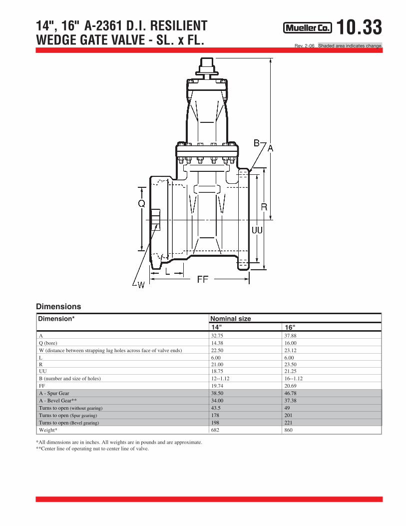
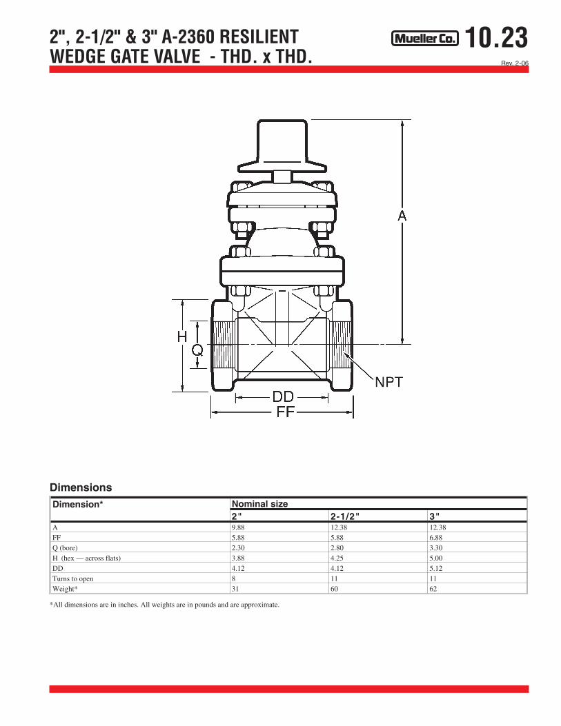
*All dimensions are in inches. All weights are in pounds and are approximate.
Dimension* Nominal size4" 6" 8" 10" 12"
A 14.19 18.00 21.50 25.50 28.62Q (bore) 4.30 6.30 8.30 10.30 12.30L 4.12 4.38 5.62 5.62 5.62R 9.00 11.00 13.50 16.00 19.00UU (bolt circle diameter for FL) 7.50 9.50 11.75 14.25 17.00B (number and size of holes for FL) 8--.75 8--.88 8--.88 12--1.00 12--1.00
FFTurns to open 14 20.5 26.5 33 38.5Weight* 90 165 260 400 565
Dimensions
W (distance between strapping lug holes across face of valve ends) 8.62 10.62 13.12 16.38 18.1210.91 12.66 14.69 15.72 16.31
A
FF
UU
R
L
B
Q
W
10.18
SEE PAGE 10.43 FOR ORDERING INSTRUCTIONS
Rev. 9-09 Shaded area indicates change.
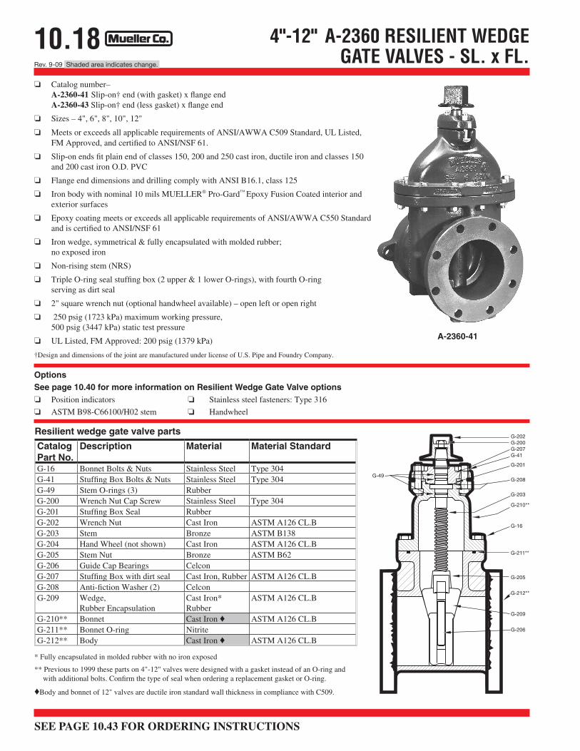
❏ Catalog number–A-2360-41 Slip-on† end (with gasket) x flange end A-2360-43 Slip-on† end (less gasket) x flange end
❏ Sizes – 4", 6", 8", 10", 12"
❏ Meets or exceeds all applicable requirements of ANSI/AWWA C509 Standard, UL Listed,FM Approved, and certified to ANSI/NSF 61.
❏ Slip-on ends fit plain end of classes 150, 200 and 250 cast iron, ductile iron and classes 150 and 200 cast iron O.D. PVC
❏ Flange end dimensions and drilling comply with ANSI B16.1, class 125
❏ Iron body with nominal 10 mils MUELLER® Pro-Gard™ Epoxy Fusion Coated interior and exterior surfaces
❏ Epoxy coating meets or exceeds all applicable requirements of ANSI/AWWA C550 Standard and is certified to ANSI/NSF 61
❏ Iron wedge, symmetrical & fully encapsulated with molded rubber;no exposed iron
❏ Non-rising stem (NRS)
❏ Triple O-ring seal stuffing box (2 upper & 1 lower O-rings), with fourth O-ringserving as dirt seal
❏ 2" square wrench nut (optional handwheel available) – open left or open right
❏ 250 psig (1723 kPa) maximum working pressure,500 psig (3447 kPa) static test pressure
❏ UL Listed, FM Approved: 200 psig (1379 kPa)
†Design and dimensions of the joint are manufactured under license of U.S. Pipe and Foundry Company.
4"-12" A-2360 RESILIENT WEDGEGATE VALVES - SL. x FL.
Options See page 10.40 for more information on Resilient Wedge Gate Valve options❏ Position indicators ❏ Stainless steel fasteners: Type 316
❏ ASTM B98-C66100/H02 stem ❏ Handwheel
A-2360-41
G-202G-200G-207G-41
G-201
G-208
G-203
G-210**
G-16
G-211**
G-205
G-212**
G-209
G-206
G-49
* Fully encapsulated in molded rubber with no iron exposed
** Previous to 1999 these parts on 4"-12" valves were designed with a gasket instead of an O-ring and with additional bolts. Confirm the type of seal when ordering a replacement gasket or O-ring.
♦Body and bonnet of 12" valves are ductile iron standard wall thickness in compliance with C509.
CatalogPart No.
Description Material Material Standard
G-16 Bonnet Bolts & Nuts Stainless Steel Type 304G-41 Stuffing Box Bolts & Nuts Stainless Steel Type 304G-49 Stem O-rings (3) RubberG-200 Wrench Nut Cap Screw Stainless Steel Type 304G-201 Stuffing Box Seal RubberG-202 Wrench Nut Cast Iron ASTM A126 CL.BG-203 Stem Bronze ASTM B138G-204 Hand Wheel (not shown) Cast Iron ASTM A126 CL.BG-205 Stem Nut Bronze ASTM B62G-206 Guide Cap Bearings CelconG-207 Stuffing Box with dirt seal Cast Iron, Rubber ASTM A126 CL.BG-208 Anti-fiction Washer (2) CelconG-209 Wedge,
Rubber EncapsulationCast Iron*Rubber
ASTM A126 CL.B
G-210** Bonnet Cast Iron ♦ ASTM A126 CL.BG-211** Bonnet O-ring NitriteG-212** Body Cast Iron ♦ ASTM A126 CL.B
Resilient wedge gate valve parts
10.17Rev. 2-06
4"-12" A-2360 RESILIENT WEDGEGATE VALVE - SL. x SL.
*All dimensions are in inches. All weights are in pounds and are approximate.
Dimension* Nominal size4" 6" 8" 10" 12"
A 14.19 18.00 21.50 25.50 28.62Q (bore) 4.30 6.30 8.30 10.30 12.30W (distance between strapping lug holes across face of valve ends) 8.62 10.62 13.12 16.38 18.12FF 12.81 14.81 17.88 18.43 18.62L 4.12 4.38 5.62 5.62 5.62DD 4.57 6.05 6.64 7.19 7.38Turns to open 14 20.5 26.5 33 38.5Weight* 90 165 260 400 565
Dimensions
A
LFF
W
DD
Q
10.16
SEE PAGE 10.43 FOR ORDERING INSTRUCTIONS
Rev. 9-09 Shaded area indicates change.
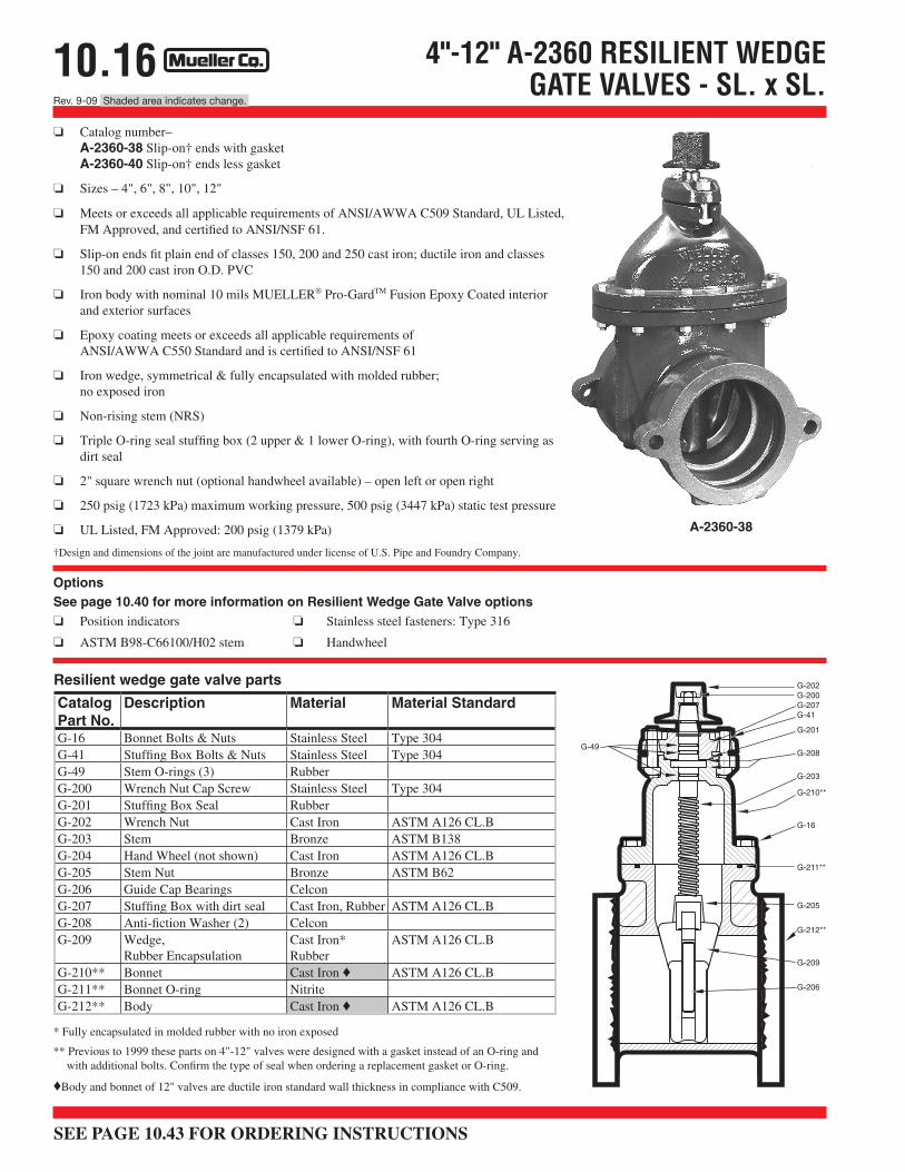
❏ Catalog number–A-2360-38 Slip-on† ends with gasket A-2360-40 Slip-on† ends less gasket
❏ Sizes – 4", 6", 8", 10", 12"
❏ Meets or exceeds all applicable requirements of ANSI/AWWA C509 Standard, UL Listed, FM Approved, and certified to ANSI/NSF 61.
❏ Slip-on ends fit plain end of classes 150, 200 and 250 cast iron; ductile iron and classes 150 and 200 cast iron O.D. PVC
❏ Iron body with nominal 10 mils MUELLER® Pro-GardTM Fusion Epoxy Coated interior and exterior surfaces
❏ Epoxy coating meets or exceeds all applicable requirements ofANSI/AWWA C550 Standard and is certified to ANSI/NSF 61
❏ Iron wedge, symmetrical & fully encapsulated with molded rubber;no exposed iron
❏ Non-rising stem (NRS)
❏ Triple O-ring seal stuffing box (2 upper & 1 lower O-ring), with fourth O-ring serving as dirt seal
❏ 2" square wrench nut (optional handwheel available) – open left or open right
❏ 250 psig (1723 kPa) maximum working pressure, 500 psig (3447 kPa) static test pressure
❏ UL Listed, FM Approved: 200 psig (1379 kPa)
†Design and dimensions of the joint are manufactured under license of U.S. Pipe and Foundry Company.
4"-12" A-2360 RESILIENT WEDGE GATE VALVES - SL. x SL.
Options See page 10.40 for more information on Resilient Wedge Gate Valve options❏ Position indicators ❏ Stainless steel fasteners: Type 316
❏ ASTM B98-C66100/H02 stem ❏ Handwheel
A-2360-38
G-202G-200G-207G-41
G-201
G-208
G-203
G-210**
G-16
G-211**
G-205
G-212**
G-209
G-206
G-49
* Fully encapsulated in molded rubber with no iron exposed
** Previous to 1999 these parts on 4"-12" valves were designed with a gasket instead of an O-ring and with additional bolts. Confirm the type of seal when ordering a replacement gasket or O-ring.
♦Body and bonnet of 12" valves are ductile iron standard wall thickness in compliance with C509.
CatalogPart No.
Description Material Material Standard
G-16 Bonnet Bolts & Nuts Stainless Steel Type 304G-41 Stuffing Box Bolts & Nuts Stainless Steel Type 304G-49 Stem O-rings (3) RubberG-200 Wrench Nut Cap Screw Stainless Steel Type 304G-201 Stuffing Box Seal RubberG-202 Wrench Nut Cast Iron ASTM A126 CL.BG-203 Stem Bronze ASTM B138G-204 Hand Wheel (not shown) Cast Iron ASTM A126 CL.BG-205 Stem Nut Bronze ASTM B62G-206 Guide Cap Bearings CelconG-207 Stuffing Box with dirt seal Cast Iron, Rubber ASTM A126 CL.BG-208 Anti-fiction Washer (2) CelconG-209 Wedge,
Rubber EncapsulationCast Iron*Rubber
ASTM A126 CL.B
G-210** Bonnet Cast Iron ♦ ASTM A126 CL.BG-211** Bonnet O-ring NitriteG-212** Body Cast Iron ♦ ASTM A126 CL.B
Resilient wedge gate valve parts
10.15Rev. 2-06
2"-12" A-2360 RESILIENT WEDGE GATE VALVE - M.J. x M.J.
*All dimensions are in inches. All weights include accessories are in pounds and are approximate.
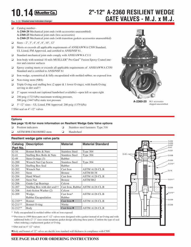
❏ Meets or exceeds all applicable requirements of ANSI/AWWA C509 Standard,UL Listed, FM Approved, and certified to ANSI/NSF 61.
❏ Standard mechanical joint ends comply with ANSI/AWWA C111
❏ Iron body with nominal 10 mils MUELLER® Pro-Gard™ Fusion Epoxy Coated inte-rior and exterior surfaces
❏ Epoxy coating meets or exceeds all applicable requirements of ANSI/AWWA C550 Standard and is certified to ANSI/NSF 61
❏ Iron wedge, symmetrical & fully encapsulated with molded rubber; no exposed iron
❏ Non-rising stem (NRS)
❏ Triple O-ring seal stuffing box (2 upper & 1 lower O-rings), with fourth O-ringserving as dirt seal††
❏ 2" square wrench nut (optional handwheel available)–-open left or open right
❏ 250 psig (1723 kPa) maximum working pressure,500 psig (3447 kPa) static test pressure
❏ 3"-12" sizes – UL Listed, FM Approved: 200 psig (1379 kPa)
††Dirt seal on 4"-12" valves
Options See page 10.40 for more information on Resilient Wedge Gate Valve options ❏ Position indicators ❏ Stainless steel fasteners: Type 316
❏ ASTM B98-C66100/H02 stem ❏ Handwheel
2"-12" A-2360 RESILIENT WEDGEGATE VALVES - M.J. x M.J.
A-2360-20 M.J. accessories shipped unassembled
G-202G-200G-207G-41
G-201
G-208
G-203
G-210**
G-16
G-211**
G-205
G-212**
G-209
G-206
G-49
* Fully encapsulated in molded rubber with no iron exposed
** Previous to 1999 these parts on 4"-12" valves were designed with a gasket instead of an O-ring and with additional bolts (2"-3" sizes retain neoprene gasket design affecting these parts). Confirm the type of seal when ordering a replacement gasket or O-ring.
††Dirt seal on 4"-12" valves
♦Body and bonnet of 12" valves are ductile iron standard wall thickness in compliance with C509.
CatalogPart No.
Description Material Material Standard
G-16 Bonnet Bolts & Nuts Stainless Steel Type 304G-41 Stuffing Box Bolts & Nuts Stainless Steel Type 304G-49 Stem O-rings (3) RubberG-200 Wrench Nut Cap Screw Stainless Steel Type 304G-201 Stuffing Box Seal RubberG-202 Wrench Nut Cast Iron ASTM A126 CL.BG-203 Stem Bronze ASTM B138G-204 Hand Wheel Cast Iron ASTM A126 CL.BG-205 Stem Nut Bronze ASTM B62G-206 Guide Cap Bearings CelconG-207 Stuffing Box with dirt seal†† Cast Iron, Rubber ASTM A126 CL.BG-208 Anti-fiction Washer (2) CelconG-209 Wedge,
Rubber EncapsulationCast Iron*Rubber
ASTM A126 CL.B
G-210** Bonnet Cast Iron ♦ ASTM A126 CL.BG-211** Bonnet O-ring NitriteG-212** Body Cast Iron ♦ ASTM A126 CL.B
Resilient wedge gate valve parts
10.13Rev. 2-06
4"-12" A-2360 RESILIENT WEDGEGATE VALVE - M.J. x FL.
* All dimensions are in inches. All weights include accessories are in pounds and are approximate.
N 9.12 11.12 13.37 15.62 17.88O (number and size of holes for MJ) 4--.88 6--.88 6--.88 8--.88 8--.88Q (bore) 4.30 6.30 8.30 10.30 12.30OO (bolt circle diameter for MJ) 7.50 9.50 11.75 14.00 16.25R 9.00 11.00 13.50 16.00 19.00UU (bolt circle diameter for FL) 7.50 9.50 11.75 14.25 17.00FF 9.50 11.00 12.00 13.88 14.44B (number and size of holes for FL) 8--.75 8--.88 8--.88 12--1.00 12--1.00Turns to open 14 20.5 26.5 33 38.5Weight* 115 168 275 400 570
Dimensions
10.12
SEE PAGE 10.43 FOR ORDERING INSTRUCTIONS
Rev. 9-09 Shaded area indicates change.
❏ Catalog number–A-2360-16 mechanical joint x flanged ends (with accessories unassembled)A-2360-19 mechanical joint x flanged ends (less accessories)
❏ Sizes – 4", 6", 8", 10", 12"
❏ Meets or exceeds all applicable requirements of ANSI/AWWA C509 Standard,UL Listed, FM Approved, and certified to ANSI/NSF 61.
❏ Flanged end dimensions and drilling comply with ANSI B16.1, class 125
❏ Mechanical joint end complies with ANSI/AWWA C111 Standard
❏ Iron body with nominal 10 mils MUELLER® Pro-Gard™ Fusion Epoxy Coated interior and exterior surfaces
❏ Epoxy coating meets or exceeds all applicable requirements of ANSI/AWWA C550 Standard and is certified to ANSI/NSF 61
❏ Iron wedge, symmetrical & fully encapsulated with molded rubber; no exposed iron
❏ Non-rising stem (NRS)
❏ Triple O-ring seal stuffing box (2 upper &1 lower O-rings), with fourthO-ring serving as dirt seal
❏ 2" square wrench nut (optional handwheel available) – open left or open right
❏ 250 psig (1723 kPa) maximum working pressure, 500 psig (3447 kPa) static test pressure
❏ UL Listed, FM Approved – 200 psig (1379 kPa)
OptionsSee page 10.40 for more information on Resilient Wedge Gate Valve options❏ Position indicators ❏ Stainless steel fasteners: Type 316
❏ ASTM B98-C66100/H02 stem ❏ Handwheel
4"-12" A-2360 RESILIENT WEDGEGATE VALVES - M.J. x FL.
A-2360-16
M.J. accessories shipped unassembled
* Fully encapsulated in molded rubber with no iron exposed
** Previous to 1999 these parts on 4"-12" valves were designed with a gasket instead of an O-ring and with additional bolts. Confirm the type of seal when ordering a replacement gasket or O-ring.
♦Body and bonnet of 12" valves are ductile iron standard wall thickness in compliance with C509.
G-202G-200G-207G-41
G-201
G-208
G-203
G-210**
G-16
G-211**
G-205
G-212**
G-209
G-206
G-49
CatalogPart No.
Description Material Material Standard
G-16 Bonnet Bolts & Nuts Stainless Steel Type 304G-41 Stuffing Box Bolts & Nuts Stainless Steel Type 304G-49 Stem O-rings (3) RubberG-200 Wrench Nut Cap Screw Stainless Steel Type 304G-201 Stuffing Box Seal RubberG-202 Wrench Nut Cast Iron ASTM A126 CL.BG-203 Stem Bronze ASTM B138G-204 Hand Wheel (not shown) Cast Iron ASTM A126 CL.BG-205 Stem Nut Bronze ASTM B62G-206 Guide Cap Bearings CelconG-207 Stuffing Box with dirt seal Cast Iron, Rubber ASTM A126 CL.BG-208 Anti-fiction Washer (2) CelconG-209 Wedge,
Rubber EncapsulationCast Iron*Rubber
ASTM A126 CL.B
G-210** Bonnet Cast Iron ♦ ASTM A126 CL.BG-211** Bonnet O-ring NitriteG-212** Body Cast Iron ♦ ASTM A126 CL.B
Resilient wedge gate valve parts
10.11Rev. 2-06
2"-12" A-2360 RESILIENT WEDGE GATE VALVE - FL. x FL.
*All dimensions are in inches. All weights are in pounds and are approximate.
* Fully encapsulated in molded rubber with no iron exposed
** Previous to 1999 these parts on 4"-12" valves were designed with a gasket instead of an O-ring and with additional bolts (2"-3" sizes retain neoprene gasket design affecting these parts). Confirm the type of seal when ordering a replacement gasket or O-ring.
††Dirt seal on 4"-12" valves
♦Body and bonnet of 12" valves are ductile iron standard wall thickness in compliance with C509.
❏ Catalog number – A-2360-6 flanged ends
❏ Sizes – 2", 2-1/2", 3", 4", 6", 8", 10", 12"
❏ Meets or exceeds all applicable requirements of ANSI/AWWA C509 Standard,UL Listed, FM Approved, and certified to ANSI/NSF 61.†
❏ Flanged end dimensions and drilling comply with ANSI B16.1, class 125
❏ Iron body with nominal 10 mils MUELLER® Pro-Gard™ Fusion Epoxy Coatedinterior and exterior surfaces
❏ Epoxy coating meets or exceeds all applicable requirements ofANSI/AWWA C550 Standard and is certified to ANSI/NSF 61
❏ Iron wedge, symmetrical & fully encapsulated with molded rubber;no exposed iron
❏ Non-rising stem (NRS)
❏ Triple O-ring seal stuffing box (2 upper & 1 lower O-rings), with fourth O-ringserving as dirt seal††
❏ Handwheel (2" square wrench nut optional) – open left or open right
❏ 250 psig (1723 kPa) maximum working pressure, 500 psig (3447 kPa) static test pressure
❏ 2-1/2"-12" sizes – UL Listed, FM Approved: 200 psig (1379 kPa)
† Approved for backflow prevention devices by USC (for 2-1/2" - 10" sizes)
††Dirt seal on 4"-12" valves
Options See page 10.40 for more information on Resilient Wedge Gate Valve options
❏ Position indicators ❏ Stainless steel fasteners: Type 316 ❏ PN 10/16 Drilling
❏ ASTM B98-C66100/H02 stem ❏ 2" square wrench nut
2"-12" A-2360 RESILIENT WEDGEGATE VALVE - FL. x FL.
A-2360-6
CatalogPart No.
Description Material Material Standard
G-16 Bonnet Bolts & Nuts Stainless Steel Type 304G-41 Stuffing Box Bolts & Nuts Stainless Steel Type 304G-49 Stem O-rings (3) RubberG-200 Wrench Nut Cap Screw Stainless Steel Type 304G-201 Stuffing Box Seal RubberG-202 Wrench Nut Cast Iron ASTM A126 CL.BG-203 Stem Bronze ASTM B138G-204 Hand Wheel Cast Iron ASTM A126 CL.BG-205 Stem Nut Bronze ASTM B62G-206 Guide Cap Bearings CelconG-207 Stuffing Box with dirt seal†† Cast Iron, Rubber ASTM A126 CL.BG-208 Anti-fiction Washer (2) CelconG-209 Wedge,
Rubber EncapsulationCast Iron*Rubber
ASTM A126 CL.B
G-210** Bonnet Cast Iron ♦ ASTM A126 CL.BG-211** Bonnet O-ring NitriteG-212** Body Cast Iron ♦ ASTM A126 CL.B
Resilient wedge gate valve parts
10.9Rev. 2-06
4"-12" A-2361 RESILIENT WEDGE GATE VALVE WITH AQUA-GRIP™ x MJ. ENDS
A
N
L
FF
Q OO
O
FKK
M
G
*All dimensions are in inches. All weights are in approximate pounds.
Dimension* Nominal size4" 6"
A 14.19 18.00
L 2.50 2.50M 4.90 7.00N 9.12 11.12O (number and size of holes for MJ) 4--.88 6--.88
Q 4.30 6.30
OO (bolt circle diameter for MJ) 7.50 9.50KK 2.75 3.75
FF 11.34 13.31
Turns to open 14 20.5Weight* 108 169
Dimensions
F 3.70 3.70
G (number and size of holes for Aqua-Grip) 4--.88 4--.88
8"21.50
2.509.1513.376--.88
8.30
11.753.75
14.72
26.5294
3.70
6--.88
10"25.50
2.5011.2015.628--.88
10.30
14.003.75
16.41
33.0395
3.89
8--.88
12"28.62
2.5013.3017.888--.88
12.30
16.253.75
16.89
38.5565
3.89
8--.88
10.8Rev. 2-06 Shaded area indicates change.
Options See page 10.40 for more information on Resilient Wedge Gate Valve options
❏ Position indicators ❏ Stainless steel fasteners: Type 316
❏ ASTM B98-C66100/H02 stem ❏ Handwheel
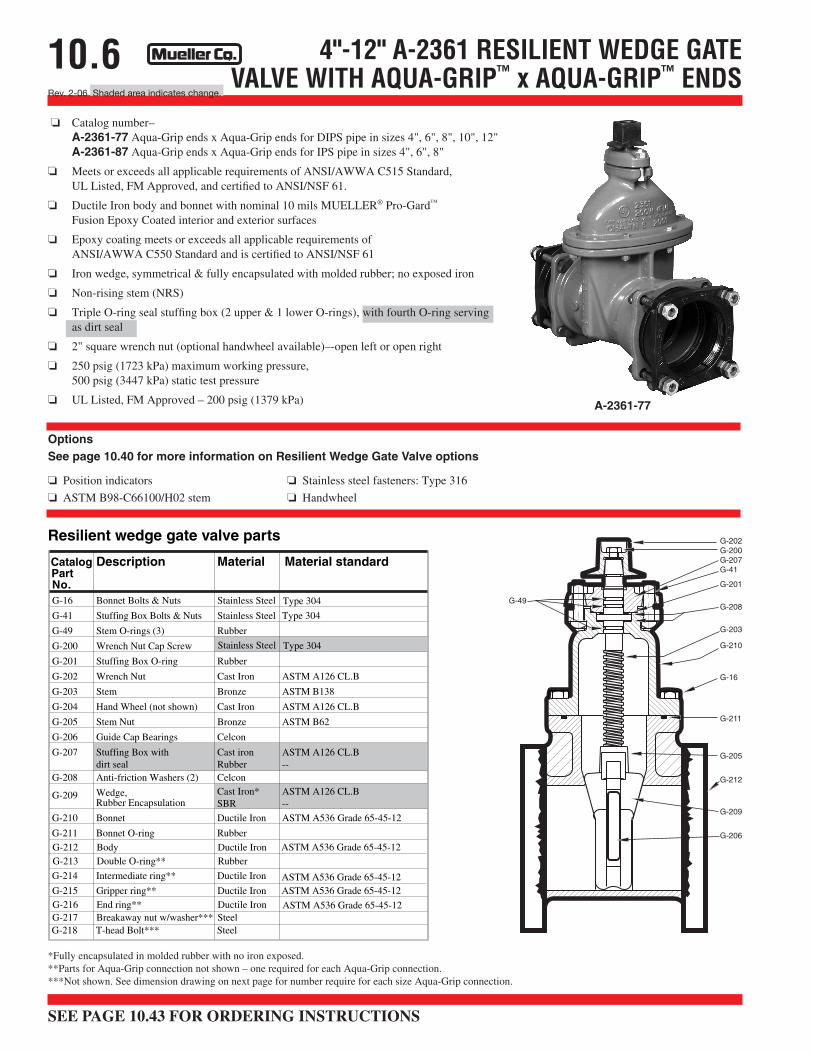
❏ Catalog number–A-2361-78 Aqua-Grip ends x mechanical joint for DIPS pipe in sizes 4", 6", 8", 10", 12"A-2361-88 Aqua-Grip ends x mechanical joint for IPS pipe in sizes 4", 6", 8"
❏ Meets or exceeds all applicable requirements of ANSI/AWWA C515 Standard, UL Listed,FM Approved, and certified to ANSI/NSF 61.
❏ Ductile Iron body and bonnet with nominal 10 mils MUELLER® Pro-Gard™ Fusion Epoxy Coated interior and exterior surfaces.
❏ Epoxy coating meets or exceeds all applicable requirements of ANSI/AWWA C550 Standard and is certified to ANSI/NSF 61.
❏ Iron wedge, symmetrical & fully encapsulated with molded rubber;no exposed iron.
❏ Non-rising stem (NRS)
❏ Triple O-ring seal stuffing box (2 upper & 1 lower O-rings), with fourth O-ring servingas dirt seal
❏ 2" square wrench nut (optional handwheel available) – open left or open right
❏ 250 psig (1723 kPa) maximum working pressure, 500 psig (3447 kPa) static test pressure
❏ UL Listed, FM Approved – 200 psig (1379 kPa)
4"-12" A-2361 RESILIENT WEDGE GATE VALVE WITH AQUA-GRIP™ x MJ. ENDS
Resilient wedge gate valve parts
CatalogPartNo.
Description Material Material standard
G-16 Bonnet Bolts & Nuts Stainless Steel Type 304
G-41 Stuffing Box Bolts & Nuts Stainless Steel Type 304
G-49 Stem O-rings (3) Rubber
G-200 Wrench Nut Cap Screw
G-201 Stuffing Box O-ring Rubber
G-202 Wrench Nut Cast Iron ASTM A126 CL.B
G-203 Stem Bronze ASTM B138
G-204 Hand Wheel (not shown) Cast Iron ASTM A126 CL.B
G-205 Stem Nut Bronze ASTM B62
G-206 Guide Cap Bearings Celcon
G-207 Stuffing Box with dirt seal
Cast ironRubber
ASTM A126 CL.B--
G-208 Anti-friction Washers (2) Celcon
G-209 Wedge,Rubber Encapsulation
Cast Iron*SBR
ASTM A126 CL.B--
G-210 Bonnet Ductile Iron ASTM A536 Grade 65-45-12
G-211 Bonnet O-ring Rubber
G-212 Body Ductile IronG-213 Double O-ring** Rubber
*Fully encapsulated in molded rubber with no iron exposed. **Parts for Aqua-Grip connection not shown – one required for each Aqua-Grip connection. ***Not shown. See dimension drawing on next page for number require for each size Aqua-Grip connection.
A-2361-78
SEE PAGE 10.43 FOR ORDERING INSTRUCTIONS
G-202G-200G-207G-41
G-201
G-208
G-203
G-210
G-16
G-211
G-205
G-212
G-209
G-206
G-49
10.7Rev. 2-06
A
F
FFKK
G
4"-12" A-2361 RESILIENT WEDGE GATE VALVE WITH AQUA-GRIP™ x AQUA-GRIP™ ENDS
*All dimensions are in inches. All weights are in approximate pounds.
Dimension* Nominal size4" 6" 8"
A 14.19 18.00 21.50
F 3.70 3.70 3.70
Turns to open 14 20.5 26.5Weight* 119 162 256
Dimensions
FF 12.68 15.12 16.94
KK 2.75 3.75 3.75
G (number and size of holes for Aqua-Grip) 4--.88 4--.88 6--.88
10"25.50
3.89
33.0380
18.06
3.75
8--.88
12"28.62
3.89
38.5475
18.90
3.75
8--.88
10.6Rev. 2-06 Shaded area indicates change.
4"-12" A-2361 RESILIENT WEDGE GATE VALVE WITH AQUA-GRIP™ x AQUA-GRIP™ ENDS
Options See page 10.40 for more information on Resilient Wedge Gate Valve options
❏ Position indicators ❏ Stainless steel fasteners: Type 316
❏ ASTM B98-C66100/H02 stem ❏ Handwheel
Resilient wedge gate valve parts
CatalogPartNo.
Description Material Material standard
G-16 Bonnet Bolts & Nuts Stainless Steel Type 304
G-41 Stuffing Box Bolts & Nuts Stainless Steel Type 304
G-49 Stem O-rings (3) Rubber
G-200 Wrench Nut Cap Screw
G-201 Stuffing Box O-ring Rubber
G-202 Wrench Nut Cast Iron ASTM A126 CL.B
G-203 Stem Bronze ASTM B138
G-204 Hand Wheel (not shown) Cast Iron ASTM A126 CL.B
G-205 Stem Nut Bronze ASTM B62
G-206 Guide Cap Bearings Celcon
G-207 Stuffing Box with dirt seal
Cast ironRubber
ASTM A126 CL.B--
G-208 Anti-friction Washers (2) Celcon
G-209 Wedge,Rubber Encapsulation
Cast Iron*SBR
ASTM A126 CL.B--
G-210 Bonnet Ductile Iron ASTM A536 Grade 65-45-12
G-211 Bonnet O-ring Rubber
G-212 Body Ductile IronG-213 Double O-ring** Rubber
*Fully encapsulated in molded rubber with no iron exposed. **Parts for Aqua-Grip connection not shown – one required for each Aqua-Grip connection. ***Not shown. See dimension drawing on next page for number require for each size Aqua-Grip connection.
A-2361-77
SEE PAGE 10.43 FOR ORDERING INSTRUCTIONS
❏ Catalog number–A-2361-77 Aqua-Grip ends x Aqua-Grip ends for DIPS pipe in sizes 4", 6", 8", 10", 12"A-2361-87 Aqua-Grip ends x Aqua-Grip ends for IPS pipe in sizes 4", 6", 8"
❏ Meets or exceeds all applicable requirements of ANSI/AWWA C515 Standard,UL Listed, FM Approved, and certified to ANSI/NSF 61.
❏ Ductile Iron body and bonnet with nominal 10 mils MUELLER® Pro-Gard™
Fusion Epoxy Coated interior and exterior surfaces
❏ Epoxy coating meets or exceeds all applicable requirements ofANSI/AWWA C550 Standard and is certified to ANSI/NSF 61
❏ Iron wedge, symmetrical & fully encapsulated with molded rubber; no exposed iron
❏ Non-rising stem (NRS)
❏ Triple O-ring seal stuffing box (2 upper & 1 lower O-rings), with fourth O-ring servingas dirt seal
❏ 2" square wrench nut (optional handwheel available)–-open left or open right
❏ 250 psig (1723 kPa) maximum working pressure, 500 psig (3447 kPa) static test pressure
❏ UL Listed, FM Approved – 200 psig (1379 kPa)
G-202G-200G-207G-41
G-201
G-208
G-203
G-210
G-16
G-211
G-205
G-212
G-209
G-206
G-49
10.5Rev. 2-06
Dimension* Nominal size4" 6" 10"
A 14.19 18.00 25.50B (number and size of holes for FL) 8--.88 8--.88 12--1.00
R 9.00 11.00 16.00
UU (bolt circle diameter for FL) 7.50 9.50 14.25
Turns to open 14 20.5 33.0Weight* 107 149 365
Dimensions
F 3.70 3.70 3.89
KK 2.75 3.75 3.75
G (number and size of holes for Aqua-Grip) 4--.88 4--.88 8--.88
8"21.508--.88
13.50
11.75
26.5225
3.70
3.75
6--.88
12"28.6212--1.00
19.00
17.00
38.5450
3.89
3.75
8--.88
FF 10.84 12.81 15.5314.22 16.45
Q (Bore) 4.30 6.30 10.308.30 12.30
T .78 .93 1.06.93 1.00
A
R
F
UU
B
KK
G
T
FF
Q
4"-12" A-2361 RESILIENT WEDGE GATE VALVE WITH AQUA-GRIP™ x FL. ENDS
*All dimensions are in inches. All weights are in approximate pounds.
10.4Rev. 2-06 Shaded area indicates change.
4"-12" A-2361 RESILIENT WEDGE GATE VALVE WITH AQUA-GRIP™ x FL. ENDS
Options
See page 10.40 for more information on Resilient Wedge Gate Valve options
❏ Position indicators ❏ Stainless steel fasteners: Type 316
❏ ASTM B98-C66100/H02 stem ❏ Handwheel
*Fully encapsulated in molded rubber with no iron exposed. **Parts for Aqua-Grip connection not shown – one required for each Aqua-Grip connection. ***Not shown. See dimension drawing on next page for number require for each size Aqua-Grip connection.
Resilient wedge gate valve parts
CatalogPartNo.
Description Material Material standard
G-16 Bonnet Bolts & Nuts Stainless Steel Type 304
G-41 Stuffing Box Bolts & Nuts Stainless Steel Type 304
G-49 Stem O-rings (3) Rubber
G-200 Wrench Nut Cap Screw
G-201 Stuffing Box O-ring Rubber
G-202 Wrench Nut Cast Iron ASTM A126 CL.B
G-203 Stem Bronze ASTM B138
G-204 Hand Wheel (not shown) Cast Iron ASTM A126 CL.B
G-205 Stem Nut Bronze ASTM B62
G-206 Guide Cap Bearings Celcon
G-207 Stuffing Box with dirt seal
Cast ironRubber
ASTM A126 CL.B--
G-208 Anti-friction Washers (2) Celcon
G-209 Wedge,Rubber Encapsulation
Cast Iron*SBR
ASTM A126 CL.B--
G-210 Bonnet Ductile Iron ASTM A536 Grade 65-45-12
G-211 Bonnet O-ring Rubber
G-212 Body Ductile IronG-213 Double O-ring** Rubber
❏ Catalog number–A-2361-76 Aqua-Grip ends x flanged ends for DIPS pipe in sizes 4", 6", 8", 10", 12"A-2361-86 Aqua-Grip ends x flanged ends for IPS pipe in sizes 4", 6", 8"
❏ Meets or exceeds all applicable requirements of ANSI/AWWA C515 Standard, UL Listed,FM Approved, and certified to ANSI/NSF 61.
❏ Flanged end dimensions and drilling comply with ANSI B16.1, class 125
❏ Ductile Iron body and bonnet with nominal 10 mils MUELLER® Pro-Gard™
Fusion Epoxy Coated interior and exterior surfaces
❏ Epoxy coating meets or exceeds all applicable requirements ofANSI/AWWA C550 Standard and is certified to ANSI/NSF 61
❏ Iron wedge, symmetrical & fully encapsulated with molded rubber; no exposed iron
❏ Non-rising stem (NRS)
❏ Triple O-ring seal stuffing box (2 upper & 1 lower O-rings), with fourth O-ring servingas dirt seal
❏ 2" square wrench nut or handwheel available – open left or open right
❏ 250 psig (1723 kPa) maximum working pressure, 500 psig (3447 kPa) static test pressure
❏ UL Listed, FM Approved – 200 psig (1379 kPa)
G-202G-200G-207G-41
G-201
G-208
G-203
G-210
G-16
G-211
G-205
G-212
G-209
G-206
G-49
10.3Rev. 2-06
10.2Rev. 9-09 Shaded area indicates change.
MUELLER® 2361 SERIES RESILIENT WEDGE GATE VALVESWITH AQUA-GRIP™ SYSTEM
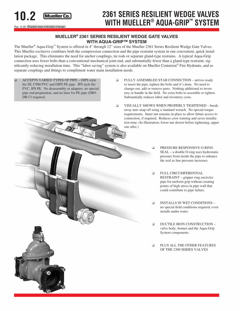
The Mueller® Aqua-Grip™ System is offered in 4" through 12" sizes of the Mueller 2361 Series Resilient Wedge Gate Valves. This Mueller exclusive combines both the compression connection and the pipe restraint system in one convenient, quick instal-lation package. This eliminates the need for anchor couplings, tie rods or separate gland-type restrains. A typical Aqua-Grip connection uses fewer bolts than a conventional mechanical joint end, and substantially fewer than a gland-type restraint, sig-nificantly reducing installation time. This “labor saving” system is also available on Mueller Centurion® Fire Hydrants, and as separate couplings and fittings to compliment water main installation needs.
2361 SERIES RESILIENT WEDGE VALVES WITH MUELLER® AQUA-GRIP™ SYSTEM
❏ ACCEPTS VARIED TYPES OF PIPE – DIPS style fits DI, C900 PVC and DIPS PE pipe. IPS style fits PVC, IPS PE. No disassembly or adapters, no special pipe end preparation, and no liner for PE pipe (DR9-DR17) required.
❏ FULLY ASSEMBLED STAB CONNECTION – arrives ready to insert the pipe, tighten the bolts and it’s done. No need to change-out, add or remove parts. Nothing additional to inven-tory or handle in the field. No extra bolts to assemble or tighten. Substantially reduces labor and inventory costs.
❏ VISUALLY SHOWS WHEN PROPERLY TIGHTENED – break-away nuts snap off using a standard wrench. No special torque requirements. Inner nut remains in place to allow future access to connection, if required. Reduces crew training and saves installa-tion time. (In illustration, lower nut shown before tightening, upper one after.)
❏ PRESSURE RESPONSIVE O-RING SEAL – a double O-ring uses hydrostatic pressure from inside the pipe to enhance the seal as line pressure increases.
❏ FULL CIRCUMFERENTIALRESTRAINT – gripper ring encircles pipe for uniform grip without creating points of high stress in pipe wall that could contribute to pipe failure.
❏ INSTALLS IN WET CONDITIONS – no special field conditions required, even installs under water.
❏ DUCTILE IRON CONSTRUCTION – valve body, bonnet and the Aqua-Grip System components.
❏ PLUS ALL THE OTHER FEATURES OF THE 2300 SERIES VALVES