236713 Internetworking Technology LAB instruction Instructor Mr.Sukchatri Prasomsuk, Ph.D. Teacher Assistant Mr.Thanapon thiradathanapattaradecha Mr. Sakpun Dangmanee School of information and communication technology, University of Phayao November 2012
Transcript
236713 Internetworking Technology
LAB instruction
Instructor
Mr.Sukchatri Prasomsuk, Ph.D.
Teacher Assistant
Mr.Thanapon thiradathanapattaradecha
Mr. Sakpun Dangmanee
School of information and communication technology,
University of Phayao
November 2012
2
Activities
Lab 1: Build a Hierarchical Topology
Evaluation: Pass Fail ……………./…………….
(Instructor signature)
LAB 2: Configuring Basic Switch Management
Evaluation: Pass Fail ……………/…………….
(Instructor signature/Date)
Lab 3: Configuring VLANs and Trunks
Evaluation: Pass Fail ……………/…………….
(Instructor signature/Date)
Lab 4: Configuring DHCP Using Easy IP
Evaluation: Pass Fail ……………/…………….
(Instructor signature/Date)
Lab 5: Configuring Extended ACLs
Evaluation: Pass Fail ……………/…………….
(Instructor signature/Date)
Lab 6: Scaling Networks with NAT
Evaluation: Pass Fail ……………/…………….
(Instructor signature/Date)
Final LAB Exam:
Pass Fail ……………/…………….
3
(Instructor signature/Date)
Lab 1
Build a Hierarchical Topology
NOTE TO USER: A PDF version of the instructions is available on the text side of the same page from which you launched this activity. Please refer to that file for a picture of the topology.
Learning Objectives
Add devices to a topology Connect the devices
Introduction:
Packet Tracer is integrated throughout this course. You must know how to navigate the Packet Tracer environment to complete this course. Use the tutorials if you need a review of Packet Tracer fundamentals. The tutorials are located in the Packet Tracer Help menu.
This activity focuses on building a hierarchical topology, from the core to the distribution and access layers.
4
Task 1: Add Devices to the Topology
Step 1. Add the missing distribution layer routers and switches.
The routers you need are located in Custom Made Devices. R1 and R3 are 1841 routers. Ctrl-click the 1841 router to add more than one. Press ESC to cancel. R2 is a 2811 router.
Now add the S1, S2, and S3 distribution layer switches using the 2960-24TT model
Step 2. Add the remaining access layer switches.
Following the topology diagram, add 2960-24TT switches to complete the rest of the access layer. Remember you can use press Ctrl-click to add multiple devices of the same type.
Step 3. Change the display name for each new device.
Click a device to open its configuration window. Select the Config tab to access the basic configuration options. In Global Settings under Display Name and Hostname, type the name for the device
shown in the topology diagram. Repeat the process for all the new devices that you added.
Although Packet Tracer does not grade adding the display names, this step must be completed to successfully complete this activity.
Step 4. Check results.
Your completion percentage should be 14%. If not, click Check Results to see which required components are not yet completed.
Task 2: Connect the Devices
Pay close attention to the topology diagram and the labeled interfaces when connecting the devices. You are graded on the connections. For instance, in the topology diagram switch S1 is connected to R1 through interface Fa0/1 on both sides. This connection is scored on both the cable type and interface designation. Do not use the Smart Connection utility to make these connections because you have no control over which interface is selected.
Step 1. Cable the core layer routers to the distribution layer routers.
Using copper crossover cables, connect the core layer routers, C1 and C2, to the distribution layer routers, R1, R2, and R3.
C1 connects to both R1 and R2, and C2 connects to both R2 and R3. As with devices, you can Ctrl-click the cable type to make multiple connections without
having to re-select the cable. Remember to refer to the topology diagram to determine which interfaces to use for
these connections.
Step 2. Cable the distribution layer routers to the access layer switches.
5
Connect the distribution layer routers to the access layer switches using copper straight-through cables. R1 connects to S1, R2 connects to S4, and R3 connects to S7.
Step 3. Cable the access layer switches.
Connect the access layer switches using copper crossover cables. Follow the topology diagram for the correct connections.
Step 4. Cable the end devices.
Connect the remaining end devices (IP phones, printers, PCs, and servers) to the correct switch using copper straight-through cables. When connecting a switch to a PC, remember to connect to the Fast Ethernet port of the PC.
Step 5. Check results.
Your completion percentage should be 100%. If not, click Check Results to see which required components are not yet completed. Note: A bug in Packet Tracer may cause your percentage to show only 99% even though all the required components are complete. If you wait long enough, Packet Tracer eventually catches up and gives you the full 100%.
NOTE TO USER: Although you can complete this activity without printed instructions, a PDF version is available on the text side of the same page from which you launched this activity.
Addressing Table
Device Interface IP Address Subnet Mask
S1 VLAN99 172.17.99.11 255.255.255.0
PC1 NIC 172.17.99.21 255.255.255.0
Server NIC 172.17.99.31 255.255.255.0
Learning Objectives
Connect to the switch using a console connection Navigate through various CLI modes Use the Help Facility to configure the clock
Access and configure command history Configure the boot sequence Configure a PC and connect it to a switch Configure full duplex Manage the MAC address table Manage the switch configuration file
7
Introduction:
Basic switch management is the foundation for configuring switches. This activity focuses on navigating command-line interface modes, using help functions, accessing the command history, configuring boot sequence parameters, setting speed and duplex settings, as well as managing the MAC address table and switch configuration file. Skills learned in this activity are necessary for configuring basic switch security in later chapters.
Task 1: Connect to the Switch
Step 1. Connect S1 and PC1.
Using a console cable, connect the RS 232 interface on PC1 to the console interface on switch S1.
Click PC1 and then click the Desktop tab. Select Terminal in the Desktop tab. Keep these default settings for Terminal Configuration and then click OK:
o Bits Per Second = 9600 o Data Bits = 8 o Parity = None o Stop Bits = 1 o Flow Control = None
You are now consoled into S1. Press Enter to get the Switch prompt.
Step 2. Check results.
Your completion percentage should be 6%. If not, click Check Results to see which required components are not yet completed.
Task 2: Navigate Through CLI Modes
Step 1. In user EXEC mode, type ?. Note the list of available commands.
While in user EXEC mode, the available commands are limited to basic monitoring commands.
Step 2. Use the enable command to go to privileged EXEC mode.
Switch>enable Switch# The prompt changes from > to #.
Step 3. In privileged EXEC mode, type ?. Note the list of available commands.
There are now more available commands compared to user EXEC mode. In addition to the basic monitoring commands, configuration and management commands can now be accessed.
Step 4. Change to global configuration mode.
Switch#configure terminal Switch(config)#
8
Step 5. In global configuration mode, type ?. Note the list of available commands.
Step 6. Configure S1 as the hostname.
Switch(config)#hostname S1 S1(config)#
Step 7. Change to interface configuration mode for VLAN99.
The interface vlan 99 command creates the interface and changes to interface configuration mode for VLAN99.
S1(config)#interface vlan 99 S1(config-if)#
Step 8. Configure VLAN99 with 172.17.99.11/24 and activate the interface.
Use the ip address and no shutdown commands to assign the correct IP address/subnet mask and activate the interface.
Step 16. Return to privileged EXEC mode using the end command.
S1(config-line)#end S1#
Step 17. Check results.
Your completion percentage should be 31%. If not, click Check Results to see which required components are not yet completed.
Task 3: Use Help Facility to Configure the Clock
Step 1. At the privileged EXEC command prompt, type clock ?.
S1#clock ? The only option is set.
Step 2. Use Help to assist setting the clock to the current time.
S1#clock ? set Set the time and date S1#clock set ? hh:mm:ss Current Time S1#clock set 12:12:12 ? <1-31> Day of the month MONTH Month of the year Continue issuing the ? command until you have completed configuring the clock. You are warned with a % Incomplete command message if the clockcommand is not fully entered with all the required arguments.
10
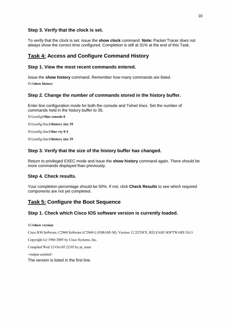
Step 3. Verify that the clock is set.
To verify that the clock is set, issue the show clock command. Note: Packet Tracer does not always show the correct time configured. Completion is still at 31% at the end of this Task.
Task 4: Access and Configure Command History
Step 1. View the most recent commands entered.
Issue the show history command. Remember how many commands are listed.
S1#show history
Step 2. Change the number of commands stored in the history buffer.
Enter line configuration mode for both the console and Telnet lines. Set the number of commands held in the history buffer to 35.
Step 3. Verify that the size of the history buffer has changed.
Return to privileged EXEC mode and issue the show history command again. There should be more commands displayed than previously.
Step 4. Check results.
Your completion percentage should be 50%. If not, click Check Results to see which required components are not yet completed.
Task 5: Configure the Boot Sequence
Step 1. Check which Cisco IOS software version is currently loaded.
S1#show version Cisco IOS Software, C2960 Software (C2960-LANBASE-M), Version 12.2(25)FX, RELEASE SOFTWARE (fc1) Copyright (c) 1986-2005 by Cisco Systems, Inc. Compiled Wed 12-Oct-05 22:05 by pt_team <output omitted> The version is listed in the first line.
11
Step 2. Check which Cisco IOS images are loaded in flash memory.
S1#show flash Directory of flash:/ 3 -rw- 4414921 c2960-lanbase-mz.122-25.FX.bin 2 -rw- 4670455 c2960-lanbase-mz.122-25.SEE1.bin 6 -rw- 616 vlan.dat 32514048 bytes total (23428056 bytes free) Note that there are two versions in flash memory. The version that is currently loaded is c2960-lanbase-mz.122-25.FX.bin.
Step 3. Configure the system to boot using a different Cisco IOS image.
In global configuration mode, issue this command.
S1(config)#boot system flash:/c2960-lanbase-mz.122-25.SEE1.bin Note: Although you can enter this command in Packet Tracer, the switch still loads the first image listed in flash.
Packet Tracer does not grade the boot system command on switches, so completion remains at 50% at the end of this task.
Task 6: Configure a PC and Connect it to a Switch
Step 1. Configure PC1 with the IP address/subnet mask 172.17.99.21/24.
Exit the terminal to return to the Desktop tab. Click IP Configuration and set the IP address to 172.17.99.21 and subnet mask to
255.255.255.0
Step 2. Connect PC1 to Fa0/18 on the switch.
Using the copper straight-through cable, connect the FastEthernet port of the PC to the Fa0/18 port on the switch.
Step 3. Test connectivity between S1 and PC1.
Ping between S1 and PC1. It may take a few attempts, but it should be successful.
Step 4. Check results.
Your completion percentage should be 69%. If not, click Check Results to see which required components are not yet completed.
Task 7: Configure Duplex and Speed
Step 1. Use the Config tab change the settings.
12
On PC1, select the Config tab. Set the bandwidth of the FastEthernet interface to 100 Mbps and Full Duplex.
Step 2. Use Cisco IOS commands to set Fa0/18.
Return to the desktop and select Terminal, and then configure the interface. S1(config)#interface fa0/18L S1(config-if)#duplex full S1(config-if)#speed 100
Step 3. Test connectivity between S1 and PC1.
Issue a ping from S1 to PC1. It may take a few attempts, but it should be successful.
Step 4. Check results.
Your completion percentage should be 81%. If not, click Check Results to see which required components are not yet completed.
Task 8: Manage the MAC Address Table
Step 1. Check the MAC address of the server.
Click the Server, then the Config tab, and then FastEthernet. The MAC Address is 0060.3EDD.19A3.
Step 2. Configure static MAC for the TFTP server.
By configuring a static MAC for the TFTP server, the switch always knows which port to use to send out traffic destined for the server. In global configuration mode on S1, add the MAC address to the addressing table of the switch:
S1(config)#mac-address-table static 0060.3EDD.19A3 vlan 99 int fa0/24
Step 3. Verify that the static MAC address is now in the MAC address table.
S1#show mac-address-table Mac Address Table ------------------------------------------- Vlan Mac Address Type Ports ---- ----------- -------- ----- 99 0060.3edd.19a3 STATIC Fa0/24 99 0060.5c5b.cd23 DYNAMIC Fa0/18 S1# Notice how the MAC address from PC1 was added dynamically. This entry may or may not be in your table depending on how long it has been since you pinged from PC1 to S1.
13
Step 4. Test connectivity between S1 and PC1.
Issue a ping from S1 to PC1. It may take a few attempts, but the command should be successful.
Packet Tracer does not grade this command. This command is needed to allow the switch to know where to send traffic destined for the server. Completion is still at 81% at the end of this task.
Task 9: Manage the Switch Configuration File
Using a copper straight-through cable, connect the FastEthernet port on the server to the Fa0/24 port on the switch.
Step 1. Enter interface configuration mode for Fa0/24.
Setting the port mode to access allows frames to be sent and received from the interface.
S1(config-if)#switchport mode access
Step 3. Assign VLAN99 to the port.
Assigning VLAN99 to the port allows the Fa0/24 interface to act as a member of VLAN 99.
S1(config-if)#switchport access vlan 99
Step 4. Verify S1 can ping the server.
Ping the server from S1. It may take a few attempts, but it should be successful.
Step 5. Back up the startup configuration to the server.
In privileged EXEC mode, copy the startup configuration to the sever. When you are prompted for the address of the remote host, enter IP address of the server, 172.17.99.31. For the destination filename, use the default filename by pressing Enter.
S1#copy startup-config tftp: Address or name of remote host []? 172.17.99.31 Destination filename [S1-confg]? [Enter]
Step 6. Verify that the server has the startup configuration.
To determine if the startup configuration was successfully transferred to the server, click the server and then click the Config tab. The S1-confg file should be listed under Services and TFTP. Note: Restoring the startup from the server is not fully simulated in Packet Tracer.
NOTE TO USER: Although you can complete this activity without printed instructions, a PDF version is available on the text side of the same page from which you launched this activity.
Addressing Table
Device Interface IP Address Subnet Mask
S1 VLAN99 172.17.99.11 255.255.255.0
PC1 NIC 172.17.99.21 255.255.255.0
PC2 NIC 172.17.99.32 255.255.255.0
Learning Objectives
Configure basic switch management Configure dynamic port security Test dynamic port security Secure unused ports
15
Task 1: Configure Basic Switch Management
Step 1. From PC1, access the console connection to S1.
Click PC1 and then the Desktop tab. Select Terminal in the Desktop tab. Keep these default settings for Terminal Configuration and then click OK:
o Bits Per Second = 9600 o Data Bits = 8 o Parity = None o Stop Bits = 1 o Flow Control = None
You are now consoled into S1. Press Enter to get the Switch prompt.
Step 2. Change to privileged EXEC mode.
To access privileged EXEC mode, type the enable command. The prompt changes from > to #.
S1>enable S1#
Notice how you were able to enter privileged EXEC mode without providing a password. Why is the lack of a privileged EXEC mode password a security threat?
Step 3. Change to global configuration mode and configure the privileged EXEC password.
While in privileged EXEC mode, you can access global configuration mode by using the configure terminal command.
Use the enable secret command to set the password. For this activity, set the password to class.
S1#configure terminal Enter configuration commands, one per line. End with CNTL/Z. S1(config)#enable secret class S1(config)#
Note: PT will not grade the enable secret command.
Step 4. Configure virtual terminal and console passwords and require users to login.
A password should be required to access the console line. Even the basic user EXEC mode can provide significant information to a malicious user. In addition, the vty lines must have a password before users can access the switch remotely.
Access the console prompt using the line console 0 command. Use the password command to configure the console and vty lines with cisco as the
password. Note: PT will not grade the password ciscocommand in this case. Then enter the login command, which requires users to enter a password before gaining
access to user EXEC mode.
16
Repeat the process with the vty lines. Use the line vty 0 15 command to access the correct prompt.
Type the exit command to return to the global configuration prompt.
The privileged EXEC password is already encrypted. To encrypt the line passwords that you just configured, enter the service password-encryptioncommand in global configuration mode.
Configure the message-of-the-day (MOTD) using Authorized Access Only as the text. The banner text is case sensitive. Make sure you do not add any spaces before or after the banner text. Use a delimiting character before and after the banner text to indicate where the text begins and ends. The delimiting character used in the example below is &, but you can use any character that is not used in the banner text. After you have configured the MOTD, log out of the switch to verify that the banner displays when you log back in.
S1(config)#banner motd &Authorized Access Only& S1(config)#end [or exit] S1#exit S1 con0 is now available Press RETURN to get started. [Enter] Authorized Access Only User Access Verification Password:
17
The password prompt now requires a password to enter user EXEC mode. Enter the password cisco.
Enter privileged EXEC mode with the password class and return to global configuration mode with the configure terminal command.
Password: [cisco] !Note: Password does not display as you type. S1>enable Password: [class] !Note: Password does not display as you type. S1#configure terminal Enter configuration commands, one per line. End with CNTL/Z. S1(config)#
Step 7. Check results.
Your completion percentage should be 40%. If not, click Check Results to see which required components are not yet completed.
Task 2: Configure Dynamic Port Security
Step 1. Enable VLAN99.
Packet Tracer opens with the VLAN 99 interface in the down state, which is not how an actual switch operates. You must enable VLAN 99 with the no shutdown command before the interface becomes active in Packet Tracer.
Your completion percentage should be 70%. If not, click Check Results to see which required components are not yet completed.
Task 3: Test Dynamic Port Security
Step 1. Remove the connection between PC1 and S1 and connect PC2 to S1.
To test port security, delete the Ethernet connection between PC1 and S1. If you accidentally delete the console cable connection, simply reconnect it.
Connect PC2 to Fa0/18 on S1. Wait for the amber link light to turn green and then ping from PC2 to S1. The port should then automatically shut down.
Step 2. Verify that port security is the reason the port is shut down.
To verify that port security has shut the port down, enter the command show interface fa0/18.
S1#show interface fa0/18 FastEthernet0/18 is down, line protocol is down (err-disabled) Hardware is Lance, address is 0090.213e.5712 (bia 0090.213e.5712) <output omitted>
The line protocol is down because of an error (err) of accepting a frame with a different MAC address than the learned MAC address, so the Cisco IOS software shut down (disabled) the port.
You can also verify a security violation with the show port-security interface fa0/18 command.
S1#show port-security interface fa0/18 Port Security : Enabled Port Status : Secure-shutdown Violation Mode : Shutdown Aging Time : 0 mins Aging Type : Absolute SecureStatic Address Aging : Disabled
20
Maximum MAC Addresses : 1 Total MAC Addresses : 1 Configured MAC Addresses : 1 Sticky MAC Addresses : 0 Last Source Address:Vlan : 00E0.F7B0.086E:99 Security Violation Count : 1
Notice that the Port Status is secure-shutdown, and the security violation count is 1.
Step 3. Restore the connection between PC1 and S1 and reset port security.
Remove the connection between PC2 and S1. Reconnect PC1 to the Fa0/18 port on S1.
Notice that the port is still down even though you reconnected the PC that is allowed on the port. A port that is in the down state because of a security violation must be manually reactivated. Shut down the port and then activate it with no shutdown.
S1#config t Enter configuration commands, one per line. End with CNTL/Z. S1(config)#interface fa0/18 S1(config-if)#shutdown %LINK-5-CHANGED: Interface FastEthernet0/18, changed state to administratively down S1(config-if)#no shutdown %LINK-5-CHANGED: Interface FastEthernet0/18, changed state to up %LINEPROTO-5-UPDOWN: Line protocol on Interface FastEthernet0/18, changed state to up %LINEPROTO-5-UPDOWN: Line protocol on Interface Vlan99, changed state to up S1(config-if)#exit S1(config)#
Step 4. Test connectivity by pinging S1 from PC1.
The ping from PC1 to S1 should be successful.
Your completion percentage should still be 70% at the end of this task.
Task 4: Secure Unused Ports
A simple method many administrators use to help secure their network from unauthorized access is to disable all unused ports on a network switch.
Step 1. Disable interface Fa0/17 on S1.
Enter interface configuration mode for FastEthernet 0/17 and shut down the port.
Step 2. Test the port by connecting PC2 to Fa0/17 on S1.
Connect PC2 to the Fa0/17 interface on S1. Notice that the link lights are red. PC2 does not have access to the network.
Step 3. Check results.
Your completion percentage should be 100%. If not, click Check Results to see which required components are not yet completed.
22
Lab 3
Configuring VLANs and Trunks
NOTE TO USER: Although you can complete this activity without printed instructions, a PDF version is available on the text side of the same page from which you launched this activity.
Learning Objectives
View the default VLAN configuration Configure VLANs Assign VLANs to ports Configure trunking
Introduction
VLANs are helpful in the administration of logical groups, allowing members of a group to be easily moved, changed, or added. This activity focuses on creating and naming VLANs, assigning access ports to specific VLANs, changing the native VLAN, and configure configuring trunk links.
Task 1: View the Default VLAN Configuration
Step 1. Verify the current running configuration on the switches.
On all three switches, enter user EXEC mode with the password cisco. Then enter privileged EXEC mode with the password class.
23
From privileged EXEC mode on all three switches, issue the show running-config command to verify the current running configuration. The basic configurations are already set, but there are no VLAN assignments.
Step 2. Display the current VLANs.
On S1, issue the show vlan command. The only VLANs present are the default ones. By default, all interfaces are assigned to VLAN 1.
Step 3. Verify connectivity between PCs on the same network.
Notice that each PC can ping the other PC that shares the same network:
PC1 can ping PC4 PC2 can ping PC5 PC3 can ping PC6
Pings to PCs in other networks fail.
What benefit will configuring VLANs provide to the current configuration?
Task 2: Configure VLANs
Step 1. Create VLANs on S1.
The command vlan vlan-id creates a VLAN. Use the name vlan-name command to name a VLAN.
On S1, create four VLANs using the vlan-ids and the names shown below:
After creating the VLANs, return to privileged EXEC and issue the show vlan brief command to verify the creation of the new VLANs.
24
S1#show vlan brief VLAN Name Status Ports ---- ------------------------------ --------- ------------------------------- 1 default active Fa0/1, Fa0/2, Fa0/3, Fa0/4 Fa0/5, Fa0/6, Fa0/7, Fa0/8 Fa0/9, Fa0/10, Fa0/11, Fa0/12 Fa0/13, Fa0/14, Fa0/15, Fa0/16 Fa0/17, Fa0/18, Fa0/19, Fa0/20 Fa0/21, Fa0/22, Fa0/23, Fa0/24 Gig1/1, Gig1/2 10 Faculty/Staff active 20 Students active 30 Guest(Default) active 99 Management&Native active 1002 fddi-default active 1003 token-ring-default active 1004 fddinet-default active 1005 trnet-default active S1#
Step 3. Create the VLANs on S2 and S3.
On S2 and S3, use the same commands you used on S1 to create and name the VLANs.
Step 4. Verify the VLAN configuration.
Use the show vlan brief command to verify all VLANs are configured and named.
Step 5. Check results.
Your completion percentage should be 38%. If not, click Check Results to see which required components are not yet completed.
Task 3: Assign VLANs to Ports
The range command greatly reduces the amount of repetitive commands you must enter when configuring the same commands on multiple ports. However, Packet Tracer does not support the range command. So only the active interfaces are graded for the switchport mode access command.
25
Step 1. Assign VLANs to the active ports on S2.
The switchport mode access command configures the interface as an access port. The switchport access vlan vlan-id command assigns a VLAN to the port. An access port can only be assigned one access VLAN. Enter the following commands on S2.
Assign VLANs to the active ports on S3. S3 uses the same VLAN access port assignments that you configured on S2.
Step 3. Verify loss of connectivity.
Previously, PCs that shared the same network could ping each other successfully. Try pinging between PC1 and PC4. Although the access ports are assigned to the appropriate VLANs, the ping fails. Why?
Step 4. Check results.
Your completion percentage should be 75%. If not, click Check Results to see which required components are not yet completed.
Task 4: Configure Trunking
Step 1. Configure S1 Fa0/1 and Fa0/3 for trunking and to use VLAN 99 as the native VLAN.
The trunk port takes about a minute to become active again. You can switch between Realtime and Simulation modes three or four times to quickly bring the port back up.
Then, the ports on S2 and S3 that connect to S1 become inactive. Again, switch between Realtime and Simulation modes three or four times to quickly bring the ports back up.
Once the ports become active, you periodically receive the following syslog messages:
%CDP-4-NATIVE_VLAN_MISMATCH: Native VLAN mismatch discovered on FastEthernet0/1 (99), with S2 FastEthernet0/1 (1). %CDP-4-NATIVE_VLAN_MISMATCH: Native VLAN mismatch discovered on FastEthernet0/3 (99), with S3 FastEthernet0/3 (1).
You configured the native VLAN on S1 to be VLAN 99. However, the native VLAN on S2 and S3 is set to the default VLAN 1.
Step 2. Verify connectivity between devices on the same VLAN.
Although there is currently a native VLAN mismatch, pings between PCs on the same VLAN are now successful. Why?
Step 3. Verify trunking is enabled on S2 and configure VLAN 99 as the native VLAN.
Dynamic Trunking Protocol (DTP) has automatically enabled the Fast Ethernet 0/1 port on S2 for trunking. Once you configured the mode to trunking on S1, DTP messages sent from S1 to S2 automatically informed S1 to move the state of Fa0/1 to trunking. This can be verified with the following command on S1:
Notice that the administrative mode is set to dynamic auto. This is the default state of all ports on a Cisco IOS switch. However, DTP has negotiated trunking, so the operation mode is trunk, resulting in a native VLAN mismatch.
27
As a best practice, configure the administrative mode of the trunking interface to be in trunk mode. This ensures that the interface is statically configured as a trunk port and never negotiates a different mode.
Configure the administrative mode of the trunking interface to be in trunk mode, and correct the native VLAN mismatch with the switchport trunk native vlan 99 command.
Step 4. Check results.
Your completion percentage should be 100%. If not, click Check Results to see which required components are not yet completed.
NOTE TO USER: Although you can complete this activity without printed instructions, a PDF version is available on the text side of the same page from which you launched this activity.
Addressing Table
Device Interface IP Address Subnet Mask
R1 Fa0/1 192.168.10.1 255.255.255.0
S0/0/0 10.1.1.1 255.255.255.252
R2
Fa0/0 192.168.20.1 255.255.255.0
S0/0/0 10.1.1.2 255.255.255.252
S0/0/1 10.2.2.1 255.255.255.252
S0/1/0 209.165.200.225 255.255.255.224
R3 Fa0/1 192.168.30.1 255.255.255.0
S0/0/0 10.2.2.2 255.255.255.252
Learning Objectives
Configure routers with Easy IP Verify that PCs are automatically configured with addressing details Configure a DNS server with DNS entries Test PC connectivity to domain names
29
Introduction
DHCP assigns IP addresses and other important network configuration information dynamically. Cisco routers can use the Cisco IOS feature set, Easy IP, as an optional, full-featured DHCP server. Easy IP leases configurations for 24 hours by default. In this activity, you will configure DHCP services on two routers and test your configuration.
Task 1: Configure Routers with Easy IP
Step 1. Configure the excluded addresses for R1 and R3.
Define a set of addresses that are reserved for hosts that need static addresses, such as servers, routers, and printers. These addresses are not included in the pool of addresses that are available for assigning to DHCP clients. For R1 and R3, exclude the first nine addresses from the DHCP pool.
Define the pool of addresses from which DHCP assigns addresses to DHCP clients on the R1 LAN. The available addresses are all addresses on the 192.168.10.0 network, except for those excluded in Step 1.
On R1, name the address pool R1LAN. Specify the address pool, default gateway, and DNS server that are assigned to each client device requesting DHCP service.
On R3, name the address pool R3LAN. Specify the address pool, default gateway, and DNS server that are assigned to each client device requesting DHCP service.
Your completion percentage should be 100%. If not, click Check Results to see which required components are not yet completed.
Task 4: Test PC Connectivity to Domain Names
Step 1. Verify that PC1 can connect to servers using the domain name.
On PC1, open the web browser and enter www.cisco.com in the address line. The web page should appear.
Step 2. Verify that PC3 can connect to servers using domain name.
On PC3, open the web browser and enter www.publicsite.com in the address line. The web page should appear All contents are Copyright (c) 1992--2007 Cisco Systems, Inc. All rights reserved. This document is Cisco Public Information.
31
Lab 5
Configuring Extended ACLs
NOTE TO USER: Although you can complete this activity without printed instructions, a PDF version is available on the text side of the same page from which you launched this activity.
Addressing Table
Device Interface IP Address Subnet Mask
R1
S0/0/0 10.1.1.1 255.255.255.252
Fa0/0 192.168.10.1 255.255.255.0
Fa0/1 192.168.11.1 255.255.255.0
R2
S0/0/0 10.1.1.2 255.255.255.252
S0/0/1 10.2.2.2 255.255.255.252
S0/1/0 209.165.200.225 255.255.255.224
Fa0/0 192.168.20.1 255.255.255.0
R3 S0/0/1 10.2.2.1 255.255.255.252
Fa0/0 192.168.30.1 255.255.255.0
ISP
S0/0/1 209.165.200.226 255.255.255.224
Fa0/0 209.165.201.1 255.255.255.224
Fa0/1 209.165.202.129 255.255.255.224
PC1 NIC 192.168.10.10 255.255.255.0
PC2 NIC 192.168.11.10 255.255.255.0
PC3 NIC 192.168.30.10 255.255.255.0
PC4 NIC 192.168.30.128 255.255.255.0
WEB/TFTP Server
NIC 192.168.20.254 255.255.255.0
WEB Server NIC 209.165.201.30 255.255.255.224
Outside Host
NIC 209.165.202.158 255.255.255.224
32
Learning Objectives
Investigate the current network configuration Evaluate a network policy and plan an ACL implementation Configure numbered extended ACLs Configure named extended ACLs
Introduction
Extended ACLs are router configuration scripts that control whether a router permits or denies packets based on their source or destination address as well as protocols or ports. Extended ACLs provide more flexibility and granularity than standard ACLs. This activity focuses on defining filtering criteria, configuring extended ACLs, applying ACLs to router interfaces, and verifying and testing the ACL implementation. The routers are already configured, including IP addresses and EIGRP routing. The user EXEC password is cisco, and the privileged EXEC password is class.
Task 1: Investigate the Current Network Configuration
Step 1. View the running configuration on the routers.
View the running configurations on all three routers using the show running-config command while in privileged EXEC mode. Notice that the interfaces and routing are fully configured. Compare the IP address configurations to the Addressing Table above. There should not be any ACLs configured on the routers at this time.
The ISP router does not require any configuration during this exercise. It is assumed that the ISP router is not under your administration and is configured and maintained by the ISP administrator.
33
Step 2. Confirm that all devices can access all other locations.
Before applying any ACLs to a network, it is important to confirm that you have fully connectivity. Without testing connectivity in your network prior to applying an ACL, troubleshooting will be very difficult.
To ensure network-wide connectivity, use the ping and tracert commands between various network devices to verify connections.
Task 2: Evaluate a Network Policy and Plan an ACL Implementation
Step 1. Evaluate the policy for the R1 LANs.
For the 192.168.10.0/24 network, block Telnet access to all locations and TFTP access to the corporate Web/TFTP server at 192.168.20.254. All other access is allowed.
For the192.168.11.0/24 network, allow TFTP access and web access to the corporate Web/TFTP server at 192.168.20.254. Block all other traffic from the 192.168.11.0/24 network to the 192.168.20.0/24 network. All other access is allowed.
Step 2. Plan the ACL implementation for the R1 LANs.
Two ACLs fully implement the security policy for the R1 LANs. The first ACL supports the first part of the policy and is configured on R1 and applied
inbound to the Fast Ethernet 0/0 interface. The second ACL supports the second part of the policy and is configured on R1 and
applied inbound to the Fast Ethernet 0/1 interface.
Step 3. Evaluate the policy for the R3 LAN.
All IP addresses of the 192.168.30.0/24 network are blocked from accessing all IP addresses of the 192.168.20.0/24 network.
The first half of 192.168.30.0/24 is allowed access to all other destinations. The second half of 192.168.30.0/24 network is allowed access to the 192.168.10.0/24
and 192.168.11.0/24 networks. The second half of 192.168.30.0/24 is allowed web and ICMP access to all remaining
destinations. All other access is implicitly denied.
Step 4. Plan the ACL implementation for the R3 LAN.
This step requires one ACL configured on R3 and applied inbound to the Fast Ethernet 0/0 interface.
Step 5. Evaluate the policy for traffic coming from the Internet via the ISP.
Outside hosts are allowed to establish a web session with the internal web server on port 80 only.
Only established TCP sessions are allowed in. Only ping replies are allowed through R2.
34
Step 6. Plan the ACL implementations for traffic coming from the Internet via the ISP.
This step requires one ACL configured on R2 and applied inbound to the Serial 0/1/0 interface.
Task 3: Configure Numbered Extended ACLs
Step 1. Determine the wildcard masks.
Two ACLs are needed to enforce the access control policy on R1. Both ACLs will be designed to deny an entire Class C network. You will configure a wildcard mask that matches all hosts on each of these Class C networks.
For example, for the entire subnet of 192.168.10.0/24 to be matched, the wildcard mask is 0.0.0.255. This can be thought of as “check, check, check, ignore” and, in essence, matches the entire 192.168.10.0/24 network.
Step 2. Configure the first extended ACL for R1.
From global configuration mode, configure the first ACL with number 110. First, you want to block Telnet to any location for all IP addresses on the 192.168.10.0/24 network.
When writing the statement, make sure that you are currently in global configuration mode.
R1(config)#access-list 110 deny tcp 192.168.10.0 0.0.0.255 any eq telnet
Next, block all IP addresses on the 192.168.10.0/24 network from TFTP access to the host at 192.168.20.254.
Block all other traffic from 192.168.11.0/24 network to the 192.168.20.0/24 network.
35
R1(config)#access-list 111 deny ip 192.168.11.0 0.0.0.255 192.168.20.0 0.0.0.255
Finally, permit any other traffic. This statement ensures that traffic from other networks is not blocked.
R1(config)#access-list 111 permit ip any any
Step 4. Verify the ACL configurations.
Confirm your configurations on R1 by issuing the show access-lists command. Your output should look like this:
R1#show access-lists Extended IP access list 110 deny tcp 192.168.10.0 0.0.0.255 any eq telnet deny udp 192.168.10.0 0.0.0.255 host 192.168.20.254 eq tftp permit ip any any Extended IP access list 111 permit tcp 192.168.11.0 0.0.0.255 host 192.168.20.254 eq www permit udp 192.168.11.0 0.0.0.255 host 192.168.20.254 eq tftp deny ip 192.168.11.0 0.0.0.255 192.168.20.0 0.0.0.255 permit ip any any
Step 5. Apply the statements to the interfaces.
To apply an ACL to an interface, enter interface configuration mode for that interface. Configure the command ip access-group access-list-number {in | out} to apply the ACL to the interface
Each ACL filters inbound traffic. Apply ACL 110 to Fast Ethernet 0/0 and ACL 111 to Fast Ethernet 0/1.
R1(config)#interface fa0/0 R1(config-if)#ip access-group 110 in R1(config-if)#interface fa0/1 R1(config-if)#ip access-group 111 in
Confirm that the ACLs appear in the running configuration of R1 and that they have been applied to the correct interfaces.
Step 6. Test the ACLs configured on R1.
Now that ACLs have been configured and applied, it is very important to test that traffic is blocked or permitted as expected.
From PC1, attempt to gain Telnet access to any device. This should be blocked.
36
From PC1, attempt to access the corporate Web/TFTP server via HTTP. This should be allowed.
From PC2, attempt to access the Web/TFTP server via HTTP. This should be allowed. From PC2, attempt to access the external Web server via HTTP. This should be allowed.
Based on your understanding of ACLs, try some other connectivity tests from PC1 and PC2.
Step 7. Check results.
Packet Tracer does not support testing TFTP access, so you will not be able to verify that policy. However, your completion percentage should be 50%. If not, click Check Results to see which required components are not yet completed.
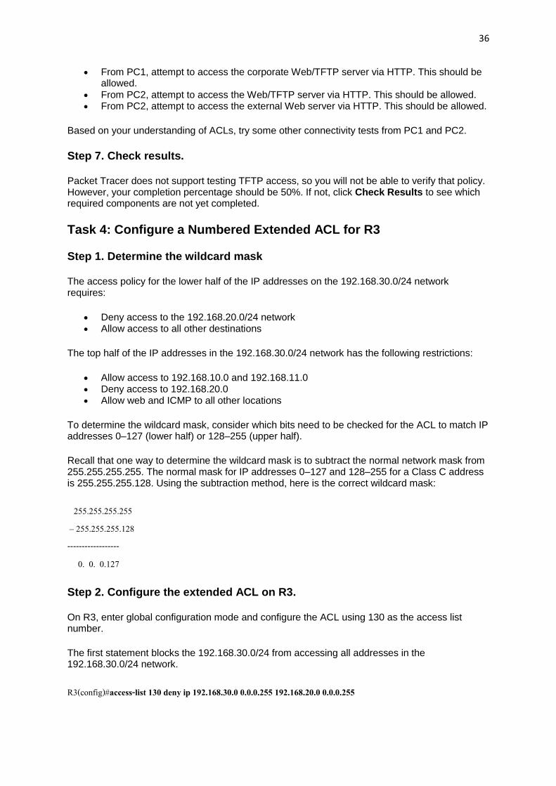
Task 4: Configure a Numbered Extended ACL for R3
Step 1. Determine the wildcard mask
The access policy for the lower half of the IP addresses on the 192.168.30.0/24 network requires:
Deny access to the 192.168.20.0/24 network Allow access to all other destinations
The top half of the IP addresses in the 192.168.30.0/24 network has the following restrictions:
Allow access to 192.168.10.0 and 192.168.11.0 Deny access to 192.168.20.0 Allow web and ICMP to all other locations
To determine the wildcard mask, consider which bits need to be checked for the ACL to match IP addresses 0–127 (lower half) or 128–255 (upper half).
Recall that one way to determine the wildcard mask is to subtract the normal network mask from 255.255.255.255. The normal mask for IP addresses 0–127 and 128–255 for a Class C address is 255.255.255.128. Using the subtraction method, here is the correct wildcard mask:
On R3, enter global configuration mode and configure the ACL using 130 as the access list number.
The first statement blocks the 192.168.30.0/24 from accessing all addresses in the 192.168.30.0/24 network.
R3(config)#access-list 130 deny ip 192.168.30.0 0.0.0.255 192.168.20.0 0.0.0.255
37
The second statement allows the lower half of the 192.168.30.0/24 network access to any other destinations.
R3(config)#access-list 130 permit ip 192.168.30.0 0.0.0.127 any
The remaining statements explicitly permit the upper half of the 192.168.30.0/24 network access to those networks and services that the network policy allows.
R3(config)#access-list 130 permit ip 192.168.30.128 0.0.0.127 192.168.10.0 0.0.0.255 R3(config)#access-list 130 permit ip 192.168.30.128 0.0.0.127 192.168.11.0 0.0.0.255 R3(config)#access-list 130 permit tcp 192.168.30.128 0.0.0.127 any eq www R3(config)#access-list 130 permit icmp 192.168.30.128 0.0.0.127 any R3(config)#access-list 130 deny ip any any
Step 3. Apply the statement to the interface.
To apply an ACL to an interface, enter interface configuration mode for that interface. Configure the command ip access-group access-list-number {in | out} to apply the ACL to the interface.
R3(config)#interface fa0/0 R3(config-if)#ip access-group 130 in
Step 4. Verify and test ACLs.
Now that the ACL has been configured and applied, it is very important to test that traffic is blocked or permitted as expected.
From PC3, ping the Web/TFTP server. This should be blocked. From PC3, ping any other device. This should be allowed. From PC4, ping the Web/TFTP server. This should be blocked. From PC4, telnet to R1 at 192.168.10.1 or 192.168.11.1. This should be allowed. From PC4, ping PC1 and PC2. This should be allowed. From PC4, telnet to R2 at 10.2.2.2. This should be blocked.
After your tests have been conducted and yield the correct results, use the show access-lists privileged EXEC command on R3 to verify that the ACL statements have matches.
Based on your understanding of ACLs, conduct other tests to verify that each statement is matching the correct traffic.
Step 5. Check results.
Your completion percentage should be 75%. If not, click Check Results to see which required components are not yet completed.
38
Task 5: Configure a Named Extended ACL
Step 1. Configure a named extended ACL on R2.
Recall that the policy on R2 will be designed to filter Internet traffic. Since R2 has the connection to the ISP, this is the best placement for the ACL
Configure a named ACL called FIREWALL on R2 using the ip access-list extended name command. This command puts the router into extended named ACL configuration mode. Note the changed router prompt.
In ACL configuration mode, add the statements to filter traffic as outlined in the policy:
Outside hosts are allowed to establish a web session with the internal web server on port 80 only.
Only established TCP sessions are allowed in. Ping replies are allowed through R2
R2(config-ext-nacl)#permit tcp any host 192.168.20.254 eq www R2(config-ext-nacl)#permit tcp any any established R2(config-ext-nacl)#permit icmp any any echo-reply R2(config-ext-nacl)#deny ip any any
After configuring the ACL on R2, use the show access-lists command to confirm that the ACL has the correct statements.
Step 2. Apply the ACL to the interface.
Use the ip access-group name {in | out} command to apply the ACL inbound on the ISP facing interface of R2.
R3(config)#interface s0/1/0 R3(config-if)#ip access-group FIREWALL in
Step 3. Verify and test ACLs.
Conduct the following tests to ensure that the ACL is functioning as expected:
From Outside Host, open a web page on the internal Web/TFTP server. This should be allowed.
From Outside Host, ping the internal Web/TFTP server. This should be blocked. From Outside Host, ping PC1. This should be blocked. From PC1, ping the external Web Server at 209.165.201.30. This should be allowed. From PC1, open a web page on the external Web Server. This should be allowed.
39
After your tests have been conducted and yield the correct results, use the show access-lists privileged EXEC command on R2 to verify that the ACL statements have matches.
Based on your understanding of ACLs, conduct other tests to verify that each statement is matching the correct traffic.
Step 4. Check results.
Your completion percentage should be 100%. If not, click Check Results to see which required components are not yet completed.
NOTE TO USER: Although you can complete this activity without printed instructions, a PDF version is available on the text side of the same page from which you launched this activity.
Addressing Table
Device Interface IP Address Subnet Mask
R1 Fa0/1 192.168.10.1 255.255.255.0
S0/0/0 10.1.1.1 255.255.255.252
R2
Fa0/0 192.168.20.1 255.255.255.0
S0/0/0 10.1.1.2 255.255.255.252
S0/0/1 10.2.2.1 255.255.255.252
S0/1/0 209.165.200.225 255.255.255.224
R3 Fa0/1 192.168.30.1 255.255.255.0
S0/0/0 10.2.2.2 255.255.255.252
Inside Web Server
NIC Local:
192.168.20.254 255.255.255.252
NIC Global:
209.165.202.131 255.255.255.252
PC1 NIC 192.168.10.10 255.255.255.0
PC3 NIC 192.168.30.10 255.255.255.0
Outside Host NIC 209.165.201.14 255.255.255.240
Public Web Server
NIC 209.265.201.30 255.255.255.240
Learning Objectives
Configure an ACL to permit NAT Configure static NAT Configure dynamic NAT Overload Configure the ISP router with static route Test connectivity
41
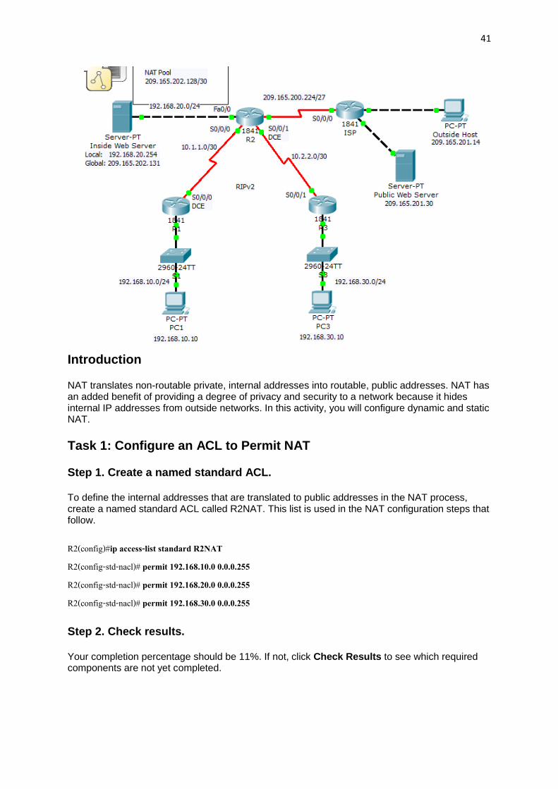
Introduction
NAT translates non-routable private, internal addresses into routable, public addresses. NAT has an added benefit of providing a degree of privacy and security to a network because it hides internal IP addresses from outside networks. In this activity, you will configure dynamic and static NAT.
Task 1: Configure an ACL to Permit NAT
Step 1. Create a named standard ACL.
To define the internal addresses that are translated to public addresses in the NAT process, create a named standard ACL called R2NAT. This list is used in the NAT configuration steps that follow.
Your completion percentage should be 11%. If not, click Check Results to see which required components are not yet completed.
42
Task 2: Configure Static NAT
Step 1. Configure static NAT for an inside web server.
The Inside Web Server needs to have a public IP address that never changes so that it can be accessed from outside the network. Configuring a static NAT address allows the web server to be configured with a private internal address. The NAT process then always maps packets using the public address of the server to the private address.
Your completion percentage should be 22%. If not, click Check Results to see which required components are not yet completed.
Task 3: Configure Dynamic NAT Overload
In addition to the public IP address assigned to Inside Web Server, the ISP has assigned three public addresses for your use. These addresses are mapped to all other internal hosts that access the Internet.
To allow more than three internal hosts to access the Internet at the same time, configure NAT with overload to accommodate the additional hosts. NAT overload, also called Port Address Translation (PAT), uses port numbers to distinguish packets from different hosts that are assigned the same public IP address.
Step 1. Define the address pool and configure dynamic NAT.
Enter the following commands to configure the pool of public addresses that are dynamically mapped to the internal hosts.
The first command defines the pool of three public addresses that are mapped to internal addresses.
The second command instructs the NAT process to map the addresses in the pool to the addresses defined in the access list you created in Task 1.
R2(config)#ip nat pool R2POOL 209.165.202.128 209.165.202.130 netmask 255.255.255.252 R2(config)#ip nat inside source list R2NAT pool R2POOL overload
Step 2. Configure the interfaces on R2 to apply NAT.
In interface configuration mode on R2, configure each of the interfaces using the ip nat {inside | outside} command. Because the internal addresses are on networks connected to the Fa0/0, Serial 0/0/0, and Serial0/0/1 interfaces, use the ip nat inside command in configuring these interfaces. The Internet is connected to Serial0/1/0, so use the ip nat outside command on this interface.
43
Step 3. Check results.
Your completion percentage should be 89%. If not, click Check Results to see which required components are not yet completed.
Task 4: Configure the ISP with a Static Route
Step 1. Configure ISP with a static route to R2.
ISP needs a static route to the public addresses of R2. Use the following command to configure this route.
Your completion percentage should be 100%. If not, click Check Results to see which required components are not yet completed.
Task 5: Test Connectivity
You should now be able to ping from any inside host to Outside Host or Public Web Server.
To see the effects of NAT on a specific packet, enter Simulation mode and observe the packet that originates from PC1.
Click the colored information box associated with that packet as it is passed from R1 to R2. By clicking Inbound PDU Details, you should see that the source address is 192.168.10.10. By clicking Outbound PDU Details, you should see that the source address has been translated to a 209.165.x.x address.
All contents are Copyright (c) 1992--2007 Cisco Systems, Inc. All rights reserved. This document is Cisco Public Information.