Structural Inspection Report Authors: Radko Radonov Reviewed by: Aidan Madden Approved by: Robert McGrath 1 East West Fashion Garments Ltd. United Fashion Trouser Ltd. Fashion Skirt & Trousers Ltd. East West Dress Pant Ltd (United Building) Ltd Chaydana, National University, Gazipur (23.957438, 90.379972) 29 rd March 2015 Revision: Issue 2 Date: 5 th August 2015 Category Amber DEA Category RED if key actions on Pages 3 & 4 are not progressed immediately
Reviewed by: Aidan MaddenApproved by: Robert McGrath
1
East West Fashion Garments Ltd. United Fashion Trouser Ltd. Fashion Skirt & Trousers Ltd.
East West Dress Pant Ltd (United Building)
Ltd
Chaydana, National University, Gazipur(23.957438, 90.379972)
29rd March 2015
Revision: Issue 2Date: 5th August 2015
Category Amber
DEA
Category RED if key actions on Pages 3 & 4 are not progressed
immediately
2
Executive Summary
On Sunday 29th April 2015, Radko Radonov of Arup carried out a visual structural survey of the United Building where are the factories of East West Fashion Garments Ltd. ; United Fashion Trouser Ltd. ; Fashion Suit & Trousers Ltd. ; East West Dress Pant Ltd. United Building is a part of East West Industrial Park complex at the address and co-ordinates given on the cover page of this report.
We met with Md. Aminul Islam (Assistant General Manager of East West Industrial Park Ltd), Md Abedur Rahman (General Manager, HR-Admin & Compliance of East West Industrial Park Ltd), Md Shahidil Islam (Factory Manager – East West Suiting Mills Ltd.). The Structural Engineer for the building was present - Engr. Utpal Kumar Dey (Managing Director, HS Engineers) as well as the representative of one the lead brands Md Nazrul Islam (Compliance officer, Linmark International Ltd). Five representatives of the Workers union were present at the close-out meeting.
The United Building is known also as Building 1 on the East West Industrial Park site. The factory is a 5 (G+4) storey industrial building with beam-column frame structural system on pad foundation. The building is increasing locally on the roof to a partial 6 storey in the area of the staircases. On the roof there are also one concrete and numerous plastic water tanks. The 5th floor is used as dining and prayer area and all other floors are used for light factory operations including sewing, cutting, printing and finished goods storage. There is a central Expansion joint through the structure. Three high-level pedestrian bridges link the building to the adjacent factories at 2nd and 4th floors.
3
Executive Summary (continued)
Construction was carried out in 1995-96. We were provided with a copy of the Permit drawings for the main building which was approved by LGED in 1995 for a 5-storey industrial building. In 2012 As-Built Architectural and Structural drawings were prepared and these were provided. The soil report is dated 1995. The Industrial Permit is dated 2012. The link bridges were added between 2001 and 2004.
The information shown on the Structural design drawings and the Industrial Permit is generally in line with the main dimensions of the building. However, there are some differences between the design documentation and the as-constructed buildings which are presented later in this report.
We have some important and urgent concerns in relation to the column stresses in the buildings. Columns appears to be stressed to levels that require immediate actions, as follows:• A Detail Engineering Assessment is required as outlined at the end of this report.• Immediate load reductions as indicated on page 4• Live loads in the building must be limited to 1.5 kPa pending the outcome of the Detail
Engineering Assessment.
If the building owners are not in a position to carry out these actions immediately, Building B1 should be classified as Category Red and evacuated. The Detail Engineering Assessment should be completed within 6 weeks of receiving this report.
4
Required Immediate Load Reductions
In the indicated zone: All live loads around the toilets and staircases must be removed immediately and these areas shall be maintained free of live loads pending completion of the DEA. Any water tanks/plinths at roof level in this area to be removed immediately. Emergency access to stairs and personnel access to toilets is permitted
5
Executive Summary (continued)
A high-level and non-exhaustive list of key concerns are:• Apparently high stress levels in columns • Loading and restrained movements on structures from Link Bridges• Vibrations on structure• Cracking• Cantilever slabs to all levels at north and south elevations• Discrepancies between drawings and as-built structure
Further actions with associated priorities and timeframes are given at the end of this report.Please note that these actions should be completed as soon as practically possible and certainly within the timeframe noted.
We have reviewed the property from an outline seismic perspective and would consider that thebuildings along with many others in the Dhaka region to have a significant risk of damage in a major Seismic event.
Our Limitations and Assumptions are also noted at the end of this report.
Note: Building N2 & N4 from East West Industrial Park were surveyed in 2014. Building N5 is the object of survey in 2015. All other buildings on site are apparently not surveyed.
6
Building Extents
7
East West Industrial Park – United Building (B1) – Factory location
Building Extent – United Building
United Building (B1)
8
East West Industrial Park – United Building – Complex layout
United Building (B1)
9
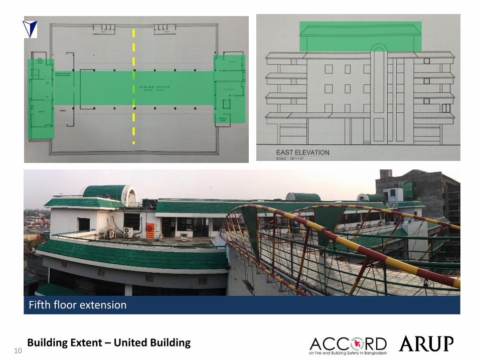
West Elevation East Elevation
North Elevation
Building Extent – United Building
10
Fifth floor extension
Building Extent – United Building
11
Building Floor Usage
Building Extent – United Building
Ground to third floor: Production
Fourth floor: Dining, Office
12
Structural Systems
13
Five (G+4) storied industrial building
Main structure composed of RC beam column with two way slab over isolated pad foundation.
Moment frame stability system
Grid dimension: See the plan
Expansion joint in the middle of the building.
Column size: Typical Int. column 610 X 380 mmEdge column 380 X 380 mm
Beam Size: 470 (D) X 420 (W)
Slab thickness: 140 mm
Floor / Ceiling Height: Avg.: 3250mm
Structural system – United Building
1,6
14
Moment frame stability system
Structural system – United Building
Expansion joint
15
Structural system – United Building
Typical Expansion joint
Inverted beam observed at roof level
16
Observations
17
Apparently high stress levels in columns
18 Observations
Preliminary calculations indicate that the working stresses of the columns at Ground Floor level are high.
19
Loading from Link Bridges
and no allowance for relative movements of bridge and buildings
20
Three elevated pedestrian walkways, linking the Main Factory Building to a sister company buildings at 2nd and 4th Floor levels. The bridges appear to have been pinned at both ends by bolted connection(apparently). Relative movement between the buildings does not appear to have been allowed. Extensive cracking of the supporting structures on both sides of the walkways is evident on site.
Observations
Extract From Master Plan
View of Walkway BridgesWalkway Bridges
Building 1
Cracks at Bridge Supports
Cracks at Bridge Supports
21
View of Walkway Bridges Cracking at Bridge Supports
Observations
22
Heavily loaded areas
23
Areas of high loading were noted at the water tanks at roof level.
Observations
Water Tanks at Roof Level
Typical Floor Plan
All water tank is 2000 L
Total no: 10
Heavy build up on passage to the bridge link (2nd floor)
24
Water Tanks at Roof Level (10 no. – Maximum 2000 litre capacity on 900mm Plinth)
Heavy load due to high build-up (700mm observed)
Observations
Vibrations on Structure
25
26
3rd Floor Plan2nd Floor Plan1st Floor Plan
Heavy vibration coming from compressor machines on 1st , 2nd and 3rd floor and affecting columns.
Observations
Cracking to Structure
27
28
Cracking was observed in a number of locations throughout the building. • Cracking was observed to areas of the façade.• Cracking on slab and perimeter wall due to not extending Expansion joint through cantilever slab.
Crack on façade Crack on slab in the cantilever at Expansion joint
Observations
29
Cantilever slabs to all levels at north and south elevations
30
The slab cantilevers to the North and South elevations from First Floor to Roof level. There are no down-stand beams supporting the cantilevering slab.
Cantilevers
Typical Floor Plan
Extent of Cantilevers from 1st Floor to Roof Level
View of Cantilever to North Elevation
31
Discrepancies between drawings and as-built structure
32
There are inconsistencies in the documents that were available for review on the day of the survey. • In the Structural drawings, the reinforcement schedule and column sizes do not appear to match.• The cantilever are not fully represented • The Link bridges are not presented in the initial design
Column Sections – Extract from Original Structural Drawings
Inconsistencies in Structural Drawings:Column Sizes do not match with Column Schedule, and Rebar quantities do not match with site observations (ferroscanner).
Observations
33
Tests carried out
34 Tests
35 Tests
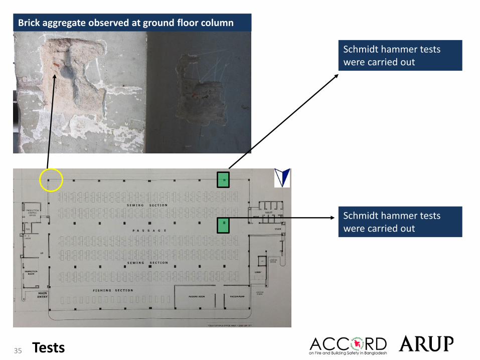
Schmidt hammer tests were carried out
Schmidt hammer tests were carried out
Brick aggregate observed at ground floor column
36
Priority Actions
37
Problems Observed
1. Apparently high stress levels in columns 2. Loading and restrained movements on structures from Link
Bridges3. Heavily loaded area4. Vibrations to structure5. Cracking to structure6. Cantilever slabs to all levels at north and south elevations7. Discrepancies between drawings and as-built structure
38
Priority 1(Immediate - Now)
Item 1 and actionsApparently high stress levels in columns
• All live loads around the toilets and staircases must be removed immediately and these areas shall be maintained free of load loads pending completion of the DEA. Water tanks and plinths in this area at roof level shall also be removed immediately.(see page 4). Emergency access to stairs and personnel access to toilets permitted
• Live load to be limited to 1.5kPa on all suspended and ground floors including cantilevers, pending outcome of Detail Engineering Assessment.
• A Detail Engineering Assessment (DEA) of Building 1 is to be commenced, see attached Scope.
• Building Engineer to review design, loads and column stresses in all Building 1 columns.
• Verify in-situ concrete stresses by 100mm dia. cores from 4 min. columns and verify grade/number of and diameter of reinforcement used.
Priority 2(within 6-weeks)
• Detail Engineering Assessment to be completed• Produce and actively manage a loading plan for all floor plates within the
Building, giving consideration to floor capacity and column capacity.
Priority 3(within 6-months)
• Actions identified in the Detail Engineering Assessment to be implemented.
• Continue to implement the load management plan.
39
This Schedule develops a minimum level of information, Analysis and testing expected as part of a Detail Engineering Assessment.The Building(s) have been visually assessed and it is deemed necessary that a detailed engineering assessment be carried out by a competent Engineering Team employed by the factory Owner. This Request should be read in conjunction with the BUET developed Tripartite Guideline document for Assessment of Structural Integrity of Existing RMG Factory Buildings in Bangladesh (Tripartite Document), the latest version of this document should be referenced. T his document also gives guidance on required competency of Engineering Team.
We expect that the following will be carried out:1. Development of Full Engineering As-Built Drawings showing Structure, loading, elements, dimensions , levels, foundations and framing on Plan,
Section and Elevation drawings .2. The Engineering team are to carry out supporting calculations with a model based design check to assess the safety and serviceability of the building
against loading as set out in BNBC-2006, Lower rate provisions can be applied in accordance with the Tripartite Guidelines following international engineering practice, justification for these lower rate provisions must be made.
3. A geotechnical Report describing ground conditions and commenting on foundation systems used/proposed.4. A report on Engineering tests carried out to justify material strengths and reinforcement content in all key elements studied.5. Detailed load plans shall be prepared for each level showing current and potential future loading with all key equipment items shown with associated
loads.6. The Engineering team will prepare an assessment report that covers the following:
• As-Built drawings including• Plans at each level calling up and dimensioning all structural components • Cross sectional drawings showing structural beams, slabs, floor to floor heights, roof build-ups and Basic design information of the
structure• Highlight any variation between As-built compared to the designed structure• Results of testing for strength and materials• Results of geotechnical assessment and testing/investigation• Details of loading, inputs and results of computer modelling• Commentary on adequacy/inadequacy of elements of the structure• Schedule of any required retrofitting required for safety or performance of Structure
Any proposals for Retrofitting to follow guidance developed in the Tripartite Document
Detail Engineering Assessment
40
Priority 1(Immediate - Now)
Item 2 and actionsLoading and restrained movements on structures from Link Bridges
• None required.
Priority 2(within 6-weeks)
• Building engineer to carry out a design check of the concentrated loads imposed on the factory building from the link bridges and confirm whether the existing structure has capacity to accommodate these loads.
• Building engineer to carry out a design check on the structure and the code conformity of the link bridges for vertical and horizontal loads.
• Building Engineer to review the connection detail of all walkways, allowing for relative movement between the buildings, to ensure that no additional loads are imparted to either building.
Priority 3(within 6-months)
• Implement any actions arising from design check.
41
Priority 1(Immediate - Now)
Item 3 and actions
Heavily loaded area
• None required.
Priority 2(within 6-weeks)
• As part of DEA, Building Engineer to confirm design loading of slabs and incorporate it into the loading plan for all floor plates.
• Produce a loading plan and actively manage the floor loading for all floor plates giving consideration to floor capacity and column capacity.
Priority 3(within 6-months)
• Implement any actions arising from design check.
42
Priority 1(Immediate - Now)
Item 4 and actionsVibrations to structure
• Note required
Priority 2(within 6-weeks)
• All the machines must be put on anti-vibration pads. The transfer of vibrations to the load bearing structure must be limited.
Priority 3(within 6-months)
• Note required.
43
Priority 1(Immediate - Now)
Item 5 and actions
Cracking to structure
• None required.
Priority 2(within 6-weeks)
• As part of the Detail Engineering Assessment (see Item 1), Building Engineer to investigate the reasons for the crack formation.
• Define the necessary remedial works.
Priority 3(within 6-months)
• Monitor cracks to beams, slabs, columns and facades. Engage a Building Engineer to investigate if cracks are only in the internal plastering.
• Building Engineer to advise on load reduction and repair and strengthening of the structure if required.
44
Priority 1(Immediate - Now)
Item 6 and actions
Cantilever slabs to all levels at north and south elevations
• None required
Priority 2(within 6-weeks)
• Building Engineer to carry out a design check of the cantilevers to ensure structural integrity of the slabs.
Priority 3(within 6-months)
• Implement any actions arising from design check.
45
Priority 1(Immediate - Now)
Item 7 and actionsDiscrepancies between drawings and as-built structure
Priority 2(within 6-weeks)
• As part of DEA, Building Engineer to survey as constructed building. Updated drawings to be prepared showing the correct as constructed layouts and roof structures.
Priority 3(within 6-months)
• None required
• None required
46
This report is for the private and confidential use of Accord for whom it was prepared together with their professional advisors as appropriate. It should not be reproduced in whole or in part or relied upon by third parties for any use without the express written permission of Arup.
This report can be used in discussion with the supplier or factory owner as a means to rectify or address any observations made. The report is not comprehensive and is limited to what could be observed during a visual inspection of the building.
This Report is not intended to be treated as a generalised inspection and does not cover the deterioration of structural members through dampness, fungal or insect attack, nor does it deal with problems and defects of a non-structural nature. Other non structural aspects of the building such as fire safety have not been assessed in this survey.
Except as otherwise noted, drains and other services were not viewed or tested during our inspection and are therefore similarly excluded from this Report. We have not inspected any parts of the structure which are covered, unexposed or inaccessible and we are therefore unable to report that any such part of the property is free from defect.
External inspection of the façade walls has generally been carried out from ground level only by visual sighting. No opening up works were carried out (except as noted) and we rely on the Architects and Engineers drawings provided to us for our views on concealed parts of the structure and in particular foundations. Strengths of materials and components are untested and we recommend that the factory owners Building Engineer carries out insitu testing over and above those suggested to satisfy themselves with the material strengths and component details.
Recommendations, where given, are for the purpose of providing indicative advice only, are not exhaustive, relate solely to identifying key and obvious structural defects as identified in this presentation, and do not take the form of or constitute a specification for works. We take no responsibility for the works as constructed. This report does not interfere with the factory owners Building Engineers responsibility for the structural performance of this building, The Building Engineer remains fully responsible for the structural adequacy of the building.
This report does not comment in detail on the future seismic performance of the building and only highlights the fact that the building may experience significant damage or collapse in a seismic event along with many others in the Dhaka region.
The observations in this report are based on the Engineering Judgement of the lead surveyor/engineer at the time of the survey. We assume in making these observations that no covering up of faults defects, filling or plastering over cracking or significant repair work has been carried out by the building owner. Any future alteration or additional work by the building owner will void this report.


![INITIAL ELECTRICAL ASSESSMENT REPORTaccord.fairfactories.org/accord_bgd_files/AllianceAuditReports/9540/5498.pdf14.17 m or 46.5 ft, [Height up to roof: 17.83 m or 58.5 ft], Stories](https://static.documents.pub/doc/80x56/5e2f7373429c853fed4404bc/initial-electrical-assessment-1417-m-or-465-ft-height-up-to-roof-1783-m-or.jpg)


