www.okotech.com Fax: +31-15-257-4233 Authors: Georgi N. Gaydadjiev, Gleb Vdovin Date of Issue: 18 Aug 2002 Version: 1.1 Store: E:\FlexibleOptical\Documentation\PCI_Card.DOC
Version Date Name Comment 1.0 04 May 2002 G. Gaydadjiev Initial Version 1.1 18 Aug 2002 G.Gaydadjiev Installation Section Complete 1.1 18 Aug 2002 G. Vdovin Corrections and updates
2 Windows Installation ....................................................................................................... 2 2.1 Plug and Play Functionality ................................................................................... 2 2.2 Windows 95/98/ME installation.............................................................................. 2 2.3 Windows NT installation........................................................................................ 2 2.4 Windows 2k and Windows XP installation ............................................................. 2 2.5 PCI and Linux ....................................................................................................... 2
3 PCI Controller Configuration ........................................................................................... 2 4 How to use the PCI controller.......................................................................................... 2
4.1 C and C++ examples ............................................................................................ 2 4.1.1 Win 9x C example.................................................................................. 2 4.1.2 Microsoft Visual C++ example ................................................................ 2 4.1.3 C example for Linux / Unix ..................................................................... 2
4.2 Example in Delphi ................................................................................................. 2 5 Warranty......................................................................................................................... 2
The OKO Tech PCI controller can be used with every Microsoft Windows OS version as well as under DOS. There are many differences between some of the windows versions. Therefore, the windows installation will be divided into the following groups: Chapter 2.2 describes the installation under Windows 95, 98 and ME; Chapter 2.3 deals with Windows NT installation; and in 2.4 Windows 2000 (and XP) installation is discussed.
2.1 Plug and Play Functionality
PC peripherals use different kind of resources dependent on their design and operation. Examples of resources are: Input / Output (I/O) address, Interrupt request (IRQ) number, Direct Memory Access (DMA) channel number and memory range. Usually resources assigned to one controller cannot be used by any other. Earlier, all those settings where configured by means of jumpers (small pin-headers and selection contact blocks). The user was supposed to keep track of any possible conflicts and resolve them in order to ensure error free operation. Adding a new device to his/hers PC was very difficult and sometimes impossible task for an inexperienced user. It is a process very suitable for automation and Apple Macintosh was the first true Plug-and Play (PnP) computer since the NuBus introduction. Soon Microsoft followed, but do to do PC devices diversity the complexity was a degree higher than for the Macintosh. The PCI bus was built with the PnP technology in mind. When the PC is powered up, the PC’s Basic Input Output System (BIOS) will scan all PCI-Devices present and reassign resources, if needed, to avoid conflicts. In case that some conflicts turn non-resolvable, BIOS will turn one of the conflicting devices off. However, this happens in very few cases.
2.2 Windows 95/98/ME installation
Windows 95, 98 and ME do support PnP. After inserting one or more PCI controllers, you should switch your PC on. Windows will detect the new PC hardware and will try to locate the corresponding driver for it.
To start the driver installation, select the Next button. After a while, you will see the following menu and should select the “Other Locations” option in order to instruct Windows where the drivers are to be found. Please select the Win9x_ME directory on the disk provided with you Flexible Optical PCI controller. You will see a screen similar to the following. By pressing Finish on the screen bellow, you will install the Flexible Optical .INF file in the Windows system directory.
The second driver you need to install is klibn.vxd driver. This driver is present in the same directory. You will be prompted by Windows to point the correct location. Pressing OK will install the klibndrv.vxd driver. After completion, you will be asked to restart your computer. Please select Yes. When your PC restarts, you will be ready to use the PCI controller. In order to use it you need to know the base address assigned to the devices by the PCI bus master. This can be done via the Start / Settings / Control Panel by double click on the System Icon. After selection, the Device Manager option you will see menu similar on the one bellow dependent on the number of PCI cards you have inserted in your PC. This picture shows a situation with two PCI controllers.
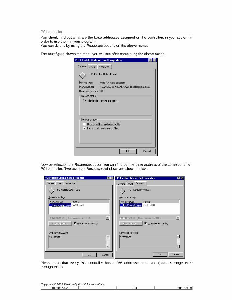
You should find out what are the base addresses assigned on the controllers in your system in order to use them in your program. You can do this by using the Properties options on the above menu. The next figure shows the menu you will see after completing the above action. Now by selection the Resources option you can find out the base address of the corresponding PCI controller. Two example Resources windows are shown bellow. Please note that every PCI controller has a 256 addresses reserved (address range xx00 through xxFF).
Simple examples of how to access every D/A channel in the I/O address space can be found in the Demo\Win9x_ME directory.
2.3 Windows NT installation
The starting point is again – PCI card is inserted, the host PC is powered on and Windows NT is started with administrator privileges . Please note that your Windows NT installation should have Service Pack 3 and above in order to allow proper work of the software. Windows NT does not support PnP functionality, therefore manual action is needed to start the installation process. On the CD you can find the Setup executable as shown bellow:
Double click on setup.exe will start the software installation. Another alternative is to start Setup.exe using the Windows “Start” menu (“Run” option). In this case, you will see the following menu. Using the Browse button please select the Win_NT\setup_drv directory and press OK.
During the installation, all the software components will be installed in your NT system. After successful completion, you will be prompted to restart the system. After restart, the installation can be verified by using Start -> Settings -> Control Panel Windows NT option. By selecting the Add/Remove Programs Icon you can view the list of all installed programs on your computer. You are supposed to see the Kolter device-driver option in your list. In case this option is absent, please repeat the installation as described above, but try to analyse eventual error messages.
Since Windows NT does not support a hardware manager as Windows 9x, an auto-detection program is used to determine the PCI cards base addresses.
The program name is TestPCI.exe and will operate under Windows NT, 2000 and XP. The only prerequisite is that the PCI card and its drivers are installed. The user first need to open the driver, and then after pressing Get all PCI devices the screen will be filled with all PCI devices detected. All detected FlexOpt devices will be surrounded by “>” and “<” signs. In addition, the jumper selection will be listed on the top of the detection window. This is important when multiple (up to four) cards are inserted in the same PC. Please note that the jumper selection is only supported by PCI cards version 2002/01 and above. In case older version card is used (as in the above figure), the user needs to determine the correspondence between the address and physical devices by trial. One suggested method can be writing at the first of the base addresses a sequence of 0 and 255 and monitoring each card’s channel 0 until square wave is detected. Repeating this procedure for every base address will help the user to determine the one-to-one relation between base addresses and physical card positions.
2.4 Windows 2k and Windows XP installation
Windows 2000 (2k) and Windows XP installation should be very similar. This is the reason why only the Windows 2000 installation will be covered by the text hereafter. In order to start the installation process, the Hardware Device Manager is required. Windows 2000 (and Windows XP) users can access the device manager through the control panel as shown hereafter. Once the Device Manger button of the Hardware option (tab) is pressed a screen similar to the following should be shown. Otherwise the PCI controller is not inserted properly or is damaged.
By selecting the PCI Device icon and by using the scroll down menu (right mouse button), the device properties menu can be accessed. It should look similar to the following window. Pressing the Reinstall Driver button will start the Upgrade Device Driver Wizard to guide through the driver installation. Due to the fact that manual device driver installation offers more flexibility, the PCI card driver is be configured that way. You should select the “Display from list…” option before proceeding with the Next button. The Other Devices -> Have Disk option is used to point to the drive and the directory containing the appropriate drivers, dependent on your windows version and configuration.
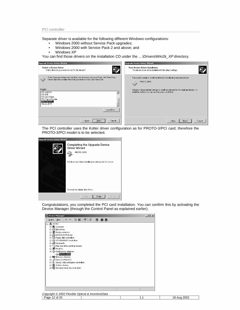
Separate driver is available for the following different Windows configurations: • Windows 2000 without Service Pack upgrades; • Windows 2000 with Service Pack 2 and above; and • Windows XP
You can find those drivers on the installation CD under the …\Drivers\Win2k_XP directory. The PCI controller uses the Kolter driver configuration as for PROTO-3/PCI card; therefore the PROTO-3/PCI model is to be selected. Congratulations, you completed the PCI card installation. You can confirm this by activating the Device Manager (through the Control Panel as explained earlier).
The card settings can also be detected automatically as explained in Windows NT installation section.
2.5 PCI and Linux
There is no PnP functionality under Linux, so the user is supposed to visit (as root) the /proc directory in order to determine the PCI card(s) base addresses. The command “more pci” will list all pci devices present and their current settings. The PROTO-3 pci base addresses are to be extracted from this list manually. Please note that in order to have direct access to the I/O address space under Linux, your program need to run with root privileges. Please use the example source supplied on the CD with the card (In the Linux directory of the installation CD) to write your own drivers.
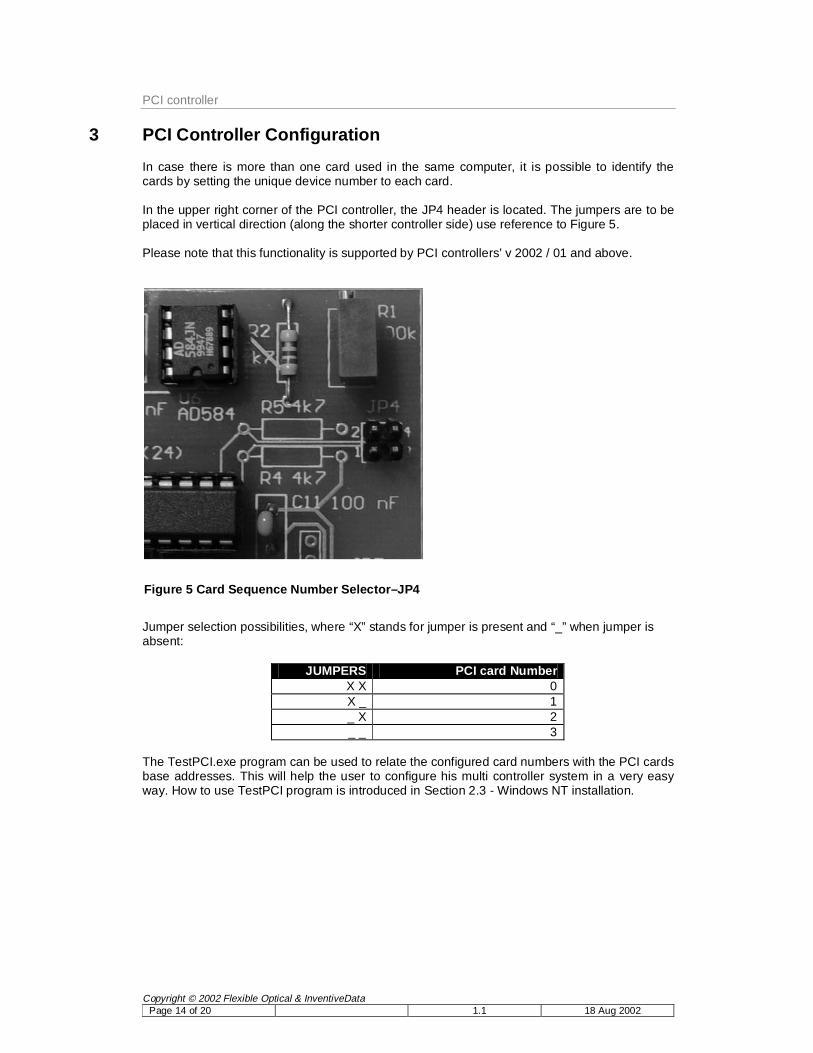
In case there is more than one card used in the same computer, it is possible to identify the cards by setting the unique device number to each card. In the upper right corner of the PCI controller, the JP4 header is located. The jumpers are to be placed in vertical direction (along the shorter controller side) use reference to Figure 5. Please note that this functionality is supported by PCI controllers’ v 2002 / 01 and above.
Jumper selection possibilities, where “X” stands for jumper is present and “_” when jumper is absent:
JUMPERS PCI card Number X X 0 X _ 1 _ X 2 _ _ 3
The TestPCI.exe program can be used to relate the configured card numbers with the PCI cards base addresses. This will help the user to configure his multi controller system in a very easy way. How to use TestPCI program is introduced in Section 2.3 - Windows NT installation.
Pinout of the OKO PCI board. To get the channel address, add the channel number multiplied by 4 to the base address. The base address is shown in /proc/pci (linux) or in device manager (Windows).
In order to use the PCI controller properly, you need to determine the base I/O addresses of all cards installed into your computer. It was already explained how to do this for different OS variants in Section 2. In addition to this, the following information is important to consider. Writing an 8-bit value (number between 0 and 255) to the base address will result in the corresponding analogue value on channel 1 of the PCI controller’s output. For example, in case you set the reference voltage to 10 Volts (using R1) and you write the value 128 to a card base address, the channel 1 output of this card will become 5 Volts (1/2 of the reference value). Because of the 32-bit nature of the PCI bus and the fact that only 8-bits are in use, every 4-th address starting from the base address corresponds to a D/A channel. The following table shows the I/O address to the channel number relation for the card.
I/O address Function Action Base address + 0 CH 1 write Base address + 4 CH 2 write Base address + 8 CH 3 write Base address + 12 CH 4 write Base address + 16 CH 5 write Base address + 20 CH 6 write Base address + 24 CH 7 write … … … Base address + 92 CH 24 write Base address + 96 JUMPER SETTINGS read
The following formulae is recommended for your application: Address_to_write_to = Base_address + ((channel_number – 1)*4) ,where channel_number value is between 1 and 24. Writing to other addresses than the ones in the table above cannot damage the card or your PC but can sometimes lead to unpredictable results on the analogue outputs. This is why you should try to avoid such write actions. Reading from the I/O addresses designated for output is not recommended.
4.1 C and C++ examples
On the CD under DEMOS\c_examples you can find a couple of simple C and C++ examples. All they will be described in the next sections.
4.1.1 Win 9x C example
Under Windows 95, 98 and ME every user has unrestricted access to the I/O address space. Because of this the external C functions _outp() and _inp() can be used to access your PCI card channels. In DEMOS\c_examples\win9x_ME directory a simple example (Microsoft Visual C++ project) is presented to show you how to read the jumper settings and write values to D/A channels. In order to use this program you need first to change the BASE_ADDREESS constant on line 14 according to your situation. Please note that the constants are in hexadecimal representation, e.g. JUMPER_OFFSET 0x60 stands for 96 as in the table earlier.
This simple program can now be compiled and executed. The program operation is as follows:
• Read the jumper settings (only cards v 2002/01 and above will return useful results) • Write at maximum speed (dependent on your computer) all the values between 0 and
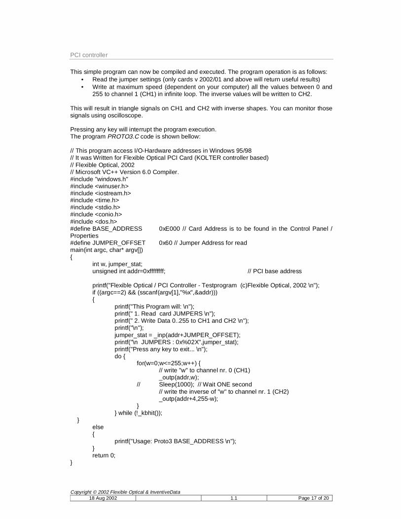
255 to channel 1 (CH1) in infinite loop. The inverse values will be written to CH2. This will result in triangle signals on CH1 and CH2 with inverse shapes. You can monitor those signals using oscilloscope. Pressing any key will interrupt the program execution. The program PROTO3.C code is shown bellow: // This program access I/O-Hardware addresses in Windows 95/98 // It was Written for Flexible Optical PCI Card (KOLTER controller based) // Flexible Optical, 2002 // Microsoft VC++ Version 6.0 Compiler. #include "windows.h" #include <winuser.h> #include <iostream.h> #include <time.h> #include <stdio.h> #include <conio.h> #include <dos.h> #define BASE_ADDRESS 0xE000 // Card Address is to be found in the Control Panel / Properties #define JUMPER_OFFSET 0x60 // Jumper Address for read main(int argc, char* argv[]) { int w, jumper_stat; unsigned int addr=0xffffffff; // PCI base address printf("Flexible Optical / PCI Controller - Testprogram (c)Flexible Optical, 2002 \n"); if ((argc==2) && (sscanf(argv[1],"%x",&addr))) { printf("This Program will: \n"); printf(" 1. Read card JUMPERS \n"); printf(" 2. Write Data 0..255 to CH1 and CH2 \n"); printf("\n"); jumper_stat = _inp(addr+JUMPER_OFFSET); printf("\n JUMPERS : 0x%02X",jumper_stat); printf("Press any key to exit... \n"); do { for(w=0;w<=255;w++) { // write "w" to channel nr. 0 (CH1) _outp(addr,w); // Sleep(1000); // Wait ONE second // write the inverse of "w" to channel nr. 1 (CH2) _outp(addr+4,255-w); } } while (!_kbhit()); } else { printf("Usage: Proto3 BASE_ADDRESS \n"); } return 0; }
The Microsoft Visual C++ project present in DEMOS\c_examples\C++\ReadWord directory is an example of how to use the PCI card under Windows NT, 2000 and XP. In those OS direct user access to I/O resources is not allowed. A device driver (already installed on your system) is available to provide you with easy object oriented interface. In order to create a new handle (to be used with one or more cards), you simply use: CDriver PortDriver("\\\\.\\PORTIO1"); From now on you can use the PortDriver object in your program. The first action required is indeed to open one or more drivers. This is done as follows: PortDriver.Open(1, BASE_ADDRESS , 0x0080); ,where 1 (1..4 are the allowed values) is the internal driver number, BASE_ADDRESS corresponds to the base address of the card you open, and 0x0080 permits your software to access the next 0x80 (128) addresses counting from the BASE_ADDRESS. This function returns TRUE or FALSE. To open a second driver you simply use: PortDriver.Open(2, BASE_ADDRESS2 , 0x0080); From now on you can read and write to the address space of your PortDriver object. In order to read you use the Read method as follows PortDriver.Read(1, ucOffset, &usValue) This function will return TRUE or FALSE and the value will be stored at the usValue location. The usValue is of unsigned char (UCHAR) type. In order to write to an address, the Write method is present. It can be used as follows: PortDriver.Write(1, ucBase+(i*4), val); In the above case the value of val will be written into the ucBase+(i*4) location and the corresponding analogue value can be measured at the addressed output. Please note that the example program on the disk never writes to CH1. The correct code (line 96) should look like: PortDriver.Write(1, ucBase+( (i -1) * 4), val); It is a good practice to destroy the handle when not needed anymore or before program termination. PortDriver.~CDriver(); This can prevent memory leaks.
4.1.3 C example for Linux / Unix
The Linux example is present in Demos\Linux directory. You can use every C compiler, e.g. gcc from gnu, available for you computer.
First you should edit the mirror.h file and set the correct the BASE1 and BASE2 addresses according to your situation. Please note that the set_dac() function is written for one or two PCI boards and specific deformable mirror in mind. In case you use more than two, you should write directly to the channels by using the write_port() function. Example get_index shows how to determine the board index reading the jumper configuration from the board in case more than one board is used in the same computer. The function call open_port() will open a handle allowing you direct I/O access. It is a good practice to use the close_port() before program termination. The write_port() and read_port() functions can be used to write values to different addresses or read the jumper configuration of you card(s).
4.2 Example in Delphi
In Demos\Delphi a very simple project can be found. Please note that in order to use this example the MMP.DLL should be installed on your PC first. In case you are interested in more Delphi examples please send an e-mail to [email protected].
If the PCI card is damaged during shipping, it will be replaced by a similar device within two months. A photo of the damaged device should be sent to OKO Technologies within 3 days after the damaged device is received. EXCEPT WHEN OTHERWISE STATED IN WRITING OKO TECHNOLOGIES AND/OR OTHER PARTIES PROVIDE THE SYSTEM "AS IS" WITHOUT WARRANTY OF ANY KIND, EITHER EXPRESSED OR IMPLIED, INCLUDING, BUT NOT LIMITED TO, THE IMPLIED WARRANTIES OF MERCHANTABILITY AND FITNESS FOR A PARTICULAR PURPOSE. THE ENTIRE RISK AS TO THE QUALITY AND PERFORMANCE OF THE EQUIPMENT IS WITH YOU. IN NO EVENT UNLESS REQUIRED BY APPLICABLE LAW OR AGREED TO IN WRITING WILL OKO TECHNOLOGIES OR INVENTIVE DATA BE LIABLE TO YOU FOR DAMAGES, INCLUDING ANY GENERAL, SPECIAL, INCIDENTAL OR CONSEQUENTIAL DAMAGES ARISING OUT OF THE USE OR INABILITY TO USE THE EQUIPMENT DESCRIBED IN THIS DOCUMENT. All questions about the technology, quality and applications of the board should be addressed to OKO Technologies.