12
2.4 GHz Wireless Adapter (WA-3) ` User Guide F1045 Rev. 202007

2.4 GHz Wireless Adapter (WA-3)
`
User Guide
F1045 Rev. 202007

Colorado Time Systems Corporate Office 1551 East 11th Street Loveland, CO 80537 USA Sales: 1-800-279-0111 or +1 970-667-1000 Service: 1-800-287-0653 or +1 970-667-1000 Service Fax: +1 970-667-1032 Web: www.coloradotime.com Email: [email protected]
Information in this manual is subject to change without notice. Pictures and illustrations may not accurately depict your version. Please check our website for the most current information; our user manuals are available online in the customer service section of our website. Part Number F1045, Rev. 202007 ©2020 Colorado Time Systems. All rights reserved.

Table of Contents Physical connection to data source ................................................................................. 1 Physical connection to scoreboard or display .................................................................. 2 Set the WA-3 switches .................................................................................................... 3 Antenna ........................................................................................................................... 4 Mounting Considerations ................................................................................................. 4 Technical Data: ............................................................................................................... 4 Standards followed .......................................................................................................... 7 European Declaration of Conformity ................................................................................ 8

www.coloradotime.com 1
The WA-3 wireless adapter is easy to set up and requires no user intervention once set up. Required cables are included with the WA-3 unless specifically noted. Set up details vary according to what you are using it to do. Please select from the options below. There are three parts to set up:
- Physical connection to data source - Physical connection to display - Set the switches on the WA-3(s)
Physical connection to data source Scoreboard data can come from a System 6 or other Colorado Time System (CTS) console, from a laptop running SynchroMM software, or from a wireless scoreboard controller (tabletop or handheld). Wireless scoreboard controllers can send data to a WA-3. System 6 or Other CTS Timer
Connect the WA-3 to AC power with the USB power adapter, and to the System 6 with an R-DC cable. Laptop Running SynchroMM or Other CTS Software
Connect the WA-3 to the USB on the laptop computer with a USB-A to USB-B cable (R-015-606). Laptop will assign a COM port number that must be selected within SynchroMM as the input. (Refer to instructions in the back of this manual on locating the assigned COM port.) Wireless Scoreboard Controller (WTTC-1 or WHC-1) No WA-3 required for transmitting.

2 [email protected] +1 970-667-1000
Physical connection to scoreboard or display Display on CTS Aquatic Scoreboard
To display data on the LED-R scoreboard(s) or P01-style mini scoreboard(s), connect the WA-3 to a scoreboard with an R-DC4 cable. Power comes to the WA-3 from the scoreboard. If you have multiple scoreboards, connect them to each other with R-DC4 cables (ordered separately). Display on Video Board
Connect the WA-3 to USB on the Display Link Plus (DL+) computer with a USB-A to USB-B cable (R-015-606). Power comes to the WA-3 via USB from the computer. Computer will assign a COM Port number that must be selected within Display Link Plus (DL+) as the input. (Refer to instructions in the back of this manual on locating assigned COM port.) Display on Multisport Scoreboard(s) Multisport scoreboards can receive data wirelessly from a WA-3 set to the same channel and PAN ID as the scoreboard. Do not try to connect a second WA-3 to the multisport scoreboard.

www.coloradotime.com 3
Set the WA-3 switches If using two WA-3s, they must be set to the same Channel and PAN IDs.
Aquatic data from System 6 (including swimming, diving, and training pace clock) Set the two WA-3s set to the same Channel and PAN IDs. Set switch 8 UP on both WA-3s.
From laptop running SynchroMM Set the two WA-3s set to the same Channel and PAN IDs. Set switch 8 UP on both WA-3s.
From Wireless Tabletop (WTTC-1) or Handheld (WHC-1) controller to the Display Link Plus (DL+) computer that controls the video board Set the WA-3 and the wireless controller to the same Channel and PAN IDs. Set switch 8 UP on the WA-3.
Water Polo from System 6 NOTE: System 6 Water Polo definitions MUST be set to default when used with a WA-3. To display data from a System 6 in Water Polo on multisport scoreboard(s) set the one WA-3 to the same Channel and PAN ID as the scoreboard(s). Set switch 8 DOWN on the WA-3. NOTE: The Multisport series board must be set to address 1 when switch 8 is in the down position. (Multisport scoreboards can be identified by part numbers beginning with “MS-” including deck clocks, portable scoreboards, and multisport mini scoreboards. The unit’s part number is printed on the serial number label on the right side of the enclosure.)
Switch settings for the WA-3 Adapter
Disconnect from power before changing the switches (labeled CONFIG). The channel and PAN ID on sending device and the channel and PAN ID on the receiving devices must match each other.
DIP switch settings
Channel Switch 1 Switch 2 Switch 3 Switch 4 0 Up Up Up Up 1 Down Up Up Up 2 Up Down Up Up 3 Down Down Up Up 4 Up Up Down Up 5 Down Up Down Up 6 Up Down Down Up 7 Down Down Down Up 8 Up Up Up Down 9 Down Up Up Down 10 Up Down Up Down 11 Down Down Up Down
Pan ID Switch 5
Switch 6
Switch 7
0 Up Up Up 1 Down Up Up 2 Up Down Up 3 Down Down Up 4 Up Up Down 5 Down Up Down 6 Up Down Down 7 Down Down Down
MODE Switch 8 Down For System 6 water polo to
multisport scoreboards Up For all other applications

4 [email protected] +1 970-667-1000
To display data from a System 6 in Water Polo on LED-R or P01-style mini scoreboard(s), set the two WA-3s to the same Channel and PAN ID. Set switch 8 UP on both WA-3s. To display data from a System 6 in Water Polo on a video board, set the two WA-3s to the same Channel and PAN ID. If you have any multisport scoreboards in this system (deck clocks, etc.), set switch 8 DOWN on both WA-3s. In DL+, use Water Polo Multisport Template items and CTS multisport interface. NOTE: The multisport series board must be set to address 1 when switch 8 is in the down position. (Multisport scoreboards can be identified by part numbers beginning with “MS-” including deck clocks, portable scoreboards, and multisport mini scoreboards. The unit’s part number is printed on the serial number label on the right side of the enclosure) If you have any CTS aquatic scoreboards in this system (LED-R, P01-style), set switch 8 UP on both WA-3s. In DL+, use Water Polo Template items and CTS aquatic interface.
Antenna Screw the antenna into the wireless adapter, and position it so that it is pointing up. Mounting Considerations The WA-3 wireless radio will transmit through non-metallic obstructions with minimal attenuation. Take care that when you mount the radio, you are not placing it in a location where a metal object will significantly block the line of sight from the transmitter to the receiver. Many facilities place the WA-3 inside an LED-R scoreboard sign panel. To do this, enlarge the hole in the back of the sign panel enclosure to accommodate the data cable and the power cable. At an outdoor installation, the sign itself is made of a Dibond, a metal bonded material. This means the antenna should be placed outside the enclosure. Use the antenna mounting extension cable (R-015-638), which is sold separately. Drill a 1/4” hole to mount the antenna outside the enclosure. Remove the nut and washer from the one end of the coaxial cable (R-015-638). Push this threaded end of the coaxial cable through the antenna hole from inside of the case. Secure it with the nut and washer from outside the case. You will need two 5/16” wrenches to do this. If the ¼” nut securing the coaxial cable to this fitting is loose, tighten it. Technical Data:
DC 5V, 500 mA

www.coloradotime.com 5
To Locate Assigned COM Port: Windows XP: Click the start button, right-click on Computer, click Manage, click on Device Manager in left pane, click on Ports in right pane.
Windows 7 & 8: Click on start button, type “device” in search, click on device manager in results, click on Ports.
6 [email protected] +1 970-667-1000
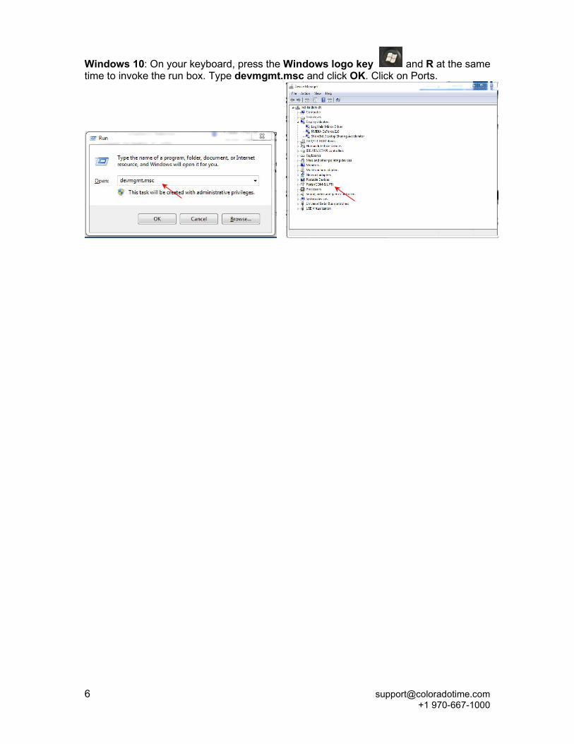
Windows 10: On your keyboard, press the Windows logo key and R at the same time to invoke the run box. Type devmgmt.msc and click OK. Click on Ports.

www.coloradotime.com 7
Standards followed UL 62368-1:2014 Ed: 2 UL Standard for Safety for Information Technology Equipment Safety Part 1: General Requirements CSA C22.2#62368-1: 2014 Ed: 2 Standard for Safety for Information Technology Equipment Safety Part 1: General Requirements FCC 47CFR 15B clB Issued: 2015/10/01 Title 47 CFR Part 15 Subpart B Unintentional Radiators Class A Verification ICES 003 Issue: 2004/01/01 Issue No.4 Interference-Causing Equipment Standard, Digital Apparatus
European Council Directive 2014/35/EU (February 26th 2014) on Low Voltage Equipment Safety Standards used:
IEC 62638-1:2014 Ed.2 and EN 60950-1:2006 Information technology equipment – Safety – Part 1: General requirements
European Council Directive 2014/30/EU (February 26th 2014) on Electromagnetic Compatibility
Standards used: CENELEC EN 55022 Issue: 2010/12/01 Information Technology Equipment – Radio Disturbance Characteristics – Limits and Methods of Measurement, Includes COR 2011: 2011/10/01 CENELAC EN 55024 Issue: 2010/11/01 Information Technology Equipment – Immunity Characteristics - Limits and Methods and Measurement CENELEC EN 61000-6-1 Issued: 2007/01/01 Electromagnetic Compatibility (EMC) Part 6-1: Generic Standards – Immunity for Residential, Commercial and Light-Industrial Environments CENELEC EN 61000-6-3 Issued: 2007/01/01 Electromagnetic Compatibility (EMC) Part 6-3: Generic Standards – Emission Standard for Residential, Commercial and Light-Industrial Environments
European Council Directive 2011/65/EU (July 21, 2011) on the Reduction of Hazardous Substances (RoHS) European Council Directive 2012/19/EU (July 4th 2012) on waste electrical and electronic equipment (WEEE) FCC Compliance Statement for WA-3 Wireless Adapter This device complies with Part 15 of the FCC Rules. Operation is subject to the following two conditions:
1. This device may not cause harmful interference. 2. This device must accept any interference received, including interference that may cause undesired operation.
This equipment has been tested and found to comply with the limits for a Class A digital device, pursuant to Part 15 of the FCC Rules. These limits are designed to provide reasonable protection against harmful interference when the equipment is operated in a commercial environment. This equipment generates, uses, and can radiate radio frequency energy and, if not installed and used in accordance with the instruction manual, may cause harmful interference to radio communications. Operation of this equipment in a residential area is likely to cause harmful interference in which case the user will be required to correct the interference at his own expense. Unauthorized modifications or changes made to this device not expressly approved by the party responsible for compliance voids the user’s authority to operate the equipment. Contains: FCC ID OUR-XBEEPRO or MCQ-XBEE3, 2.4GHz transmitter Contains: Model xBeePRO Radio, IC: 4214-XBEEPRO or xBee3 Radio, IC: 1846A-XBEE3

8 [email protected] +1 970-667-1000
European Declaration of Conformity We,
Everlast Climbing Industries, Inc. DBA Colorado Time Systems 1551 E 11th Street Loveland, CO 80537, USA ++1 970 667 1000 www.coloradotime.com
declare under our sole responsibility that the
Product: Wireless Adapter, 2.4 GHz Model numbers: WA-3
to which this declaration relates is in conformity with the following European Directives: European Council Directive 2014/35/EU (February 26th 2014) on Low Voltage Equipment Safety Standards used:
IEC 62368-1:2014 Ed.2 and EN 60950-1:2006 Information technology equipment – Safety – Part 1: General requirements
European Council Directive 2014/30/EU (February 26th 2014) on Electromagnetic Compatibility
Standards used: CENELEC EN 55022 Issue: 2010/12/01 Information Technology Equipment – Radio Disturbance Characteristics – Limits and Methods of Measurement, Includes COR 2011: 2011/10/01 CENELAC EN 55024 Issue: 2010/11/01 Information Technology Equipment – Immunity Characteristics - Limits and Methods and Measurement CENELEC EN 61000-6-1 Issued: 2007/01/01 Electromagnetic Compatibility (EMC) Part 6-1: Generic Standards – Immunity for Residential, Commercial and Light-Industrial Environments CENELEC EN 61000-6-3 Issued: 2007/01/01 Electromagnetic Compatibility (EMC) Part 6-3: Generic Standards – Emission Standard for Residential, Commercial and Light-Industrial Environments
European Council Directive 2011/65/EU (July 21, 2011) on the Reduction of Hazardous Substances (RoHS) European Council Directive 2012/19/EU (July 4th 2012) on waste electrical and electronic equipment (WEEE) The Technical Construction File is maintained at the corporate headquarters of Colorado Time Systems in Colorado, USA.
Date of issue: December 20, 2013 Place of issue: Loveland, Colorado, USA
XMichael Medina-BrodskyDirector of Manufacturing and Technology

Customer Service Department www.coloradotime.com Email: [email protected] Phone: +1 970-667-1000 Toll Free U.S. and Canada 1-800-287-0653 Fax: +1 970-667-1032


