240 Series DIN Panel Meters 8 Features An extensive range of specialist measuring meters in 4 case sizes Shock resistant taut band suspension Vibration-proof Hi-Q damping Slide in dials for 90°current, voltage and frequency on models 242, 243 and 244 Terminal covers supplied as standard Benefits Low cost Local indication Ease of installation Minimal training Low maintenance Customised options and features Applications Switchgear Distribution systems Generator sets Control panels Energy management Building management Utility power monitoring Process control Motor control Approvals LRS and BV Approvals. An extensive range of 48, 72, 96 and 144mm DIN style panel meters offering measurement of all electrical and electronic parameters. Meters are shock resistant and vibration proof and supplied with terminal covers. A selection of slide in dials and customised options are available. Movements In Crompton Instruments’ world-patented ‘Hi-Q’ taut band suspension, all the delicate parts of the traditional instruments are eliminated. There are no pivots, no jewel bearings, no hair-springs and no air damping vane. Instead, a tough platinum ribbon suspends the moving element between front and rear tension springs. Specially contoured pads are fitted to the ends of the spindle, and the working gap at each end is filled with a high quality silicon fluid. The pads, together with the fluid reservoir, form a system which acts as a resilient built-in shock absorber. This provides both rotational and longitudinal damping as the moving element floats on oil with no bearing friction and is effectively cushioned against shock and vibration. 360° Synchroscopes and power factor meters have robust pivot and jewel bearings with oil damping. Dials, Scales and Pointers Standard dials are matt white with black printed scales and bar knife-edge pointers. Black dials with white or yellow scales and pointers are also available. Interchangeable slide in dials are used on models 242, 243 and 244 90° moving iron, moving coil and frequency meters. General options include red supplementary pointers, red indexes (quadrant scales), red, green or blue lines, bands or segments, finely spaced divisions, multi-scales, special scales and captions to customer' requirements. Illumination Internal illumination is available in the following models: • 244 and 246 shortscale moving coil and moving iron vane. • 243, 244 and 246 longscale moving coil and moving iron vane. Through dial (Translucent) illumination on 244 and 246 models. Edge illumination on 243, 244 and 246 models. Replaceable 6, 12 or 24V lamps are used on all models except 243 longscale meters, where the lamps are internal. Specification Performance BSEN60051 Measuring Ranges DIN 43701 Accuracy Overload BSEN60051 Dimensions DIN 43700 Scale Marking Generally DIN43802 Magnetic Influence BSEN60051 Safety IEC414 Terminals Clamp strap M4 up to 25A. Clamp strap M8 over 25A Humidity Range Up to 95% RH (non condensing) Test Voltage @50Hz 2kV RMS for 1 minute Overload AC Current x 1.2 continuous x 10 for 5 seconds Overload AC Voltage x 1.2 continuous x 2 for 5 seconds Frequency See main pages for other instruments Damping Time Less than 3 seconds is standard. More heavily damped movements are available on request. Standard Calibration 23°C Operating Temperature -20°C to +60°C Enclosure Code IP54 as standard (to BSEN60529). IP55 consult factory Terminals IP20B with terminal cover or terminal boots fitted Case Grade UL94V0 Base Grade UL94V1
Transcript
240 Series DIN Panel Meters
8
Features
An extensive range of specialistmeasuring meters in 4 case sizes
Shock resistant taut band suspension
Vibration-proof Hi-Q damping
Slide in dials for 90°current, voltage andfrequency on models 242, 243 and 244
Terminal covers supplied as standard
Benefits
Low cost
Local indication
Ease of installation
Minimal training
Low maintenance
Customised options and features
Applications
Switchgear
Distribution systems
Generator sets
Control panels
Energy management
Building management
Utility power monitoring
Process control
Motor control
Approvals
LRS and BV Approvals.
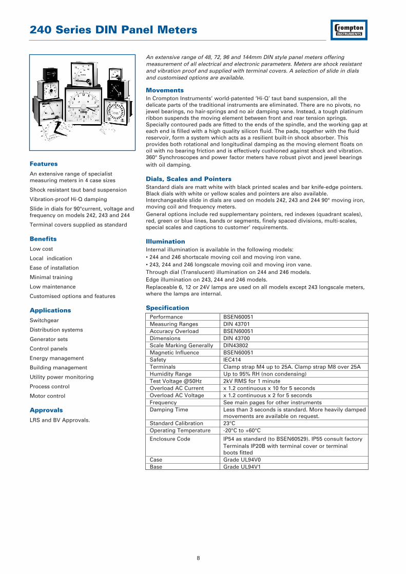
An extensive range of 48, 72, 96 and 144mm DIN style panel meters offeringmeasurement of all electrical and electronic parameters. Meters are shock resistantand vibration proof and supplied with terminal covers. A selection of slide in dialsand customised options are available.
Movements In Crompton Instruments’ world-patented ‘Hi-Q’ taut band suspension, all thedelicate parts of the traditional instruments are eliminated. There are no pivots, nojewel bearings, no hair-springs and no air damping vane. Instead, a tough platinumribbon suspends the moving element between front and rear tension springs.Specially contoured pads are fitted to the ends of the spindle, and the working gap ateach end is filled with a high quality silicon fluid. The pads, together with the fluidreservoir, form a system which acts as a resilient built-in shock absorber. Thisprovides both rotational and longitudinal damping as the moving element floats onoil with no bearing friction and is effectively cushioned against shock and vibration.360° Synchroscopes and power factor meters have robust pivot and jewel bearingswith oil damping.
Dials, Scales and Pointers Standard dials are matt white with black printed scales and bar knife-edge pointers.Black dials with white or yellow scales and pointers are also available.Interchangeable slide in dials are used on models 242, 243 and 244 90° moving iron,moving coil and frequency meters.General options include red supplementary pointers, red indexes (quadrant scales),red, green or blue lines, bands or segments, finely spaced divisions, multi-scales,special scales and captions to customer' requirements.
Illumination Internal illumination is available in the following models:• 244 and 246 shortscale moving coil and moving iron vane.• 243, 244 and 246 longscale moving coil and moving iron vane.Through dial (Translucent) illumination on 244 and 246 models.Edge illumination on 243, 244 and 246 models.Replaceable 6, 12 or 24V lamps are used on all models except 243 longscale meters,where the lamps are internal.
Specification Performance BSEN60051Measuring Ranges DIN 43701Accuracy Overload BSEN60051Dimensions DIN 43700Scale Marking Generally DIN43802Magnetic Influence BSEN60051Safety IEC414Terminals Clamp strap M4 up to 25A. Clamp strap M8 over 25AHumidity Range Up to 95% RH (non condensing)Test Voltage @50Hz 2kV RMS for 1 minuteOverload AC Current x 1.2 continuous x 10 for 5 secondsOverload AC Voltage x 1.2 continuous x 2 for 5 secondsFrequency See main pages for other instrumentsDamping Time Less than 3 seconds is standard. More heavily damped
movements are available on request.Standard Calibration 23°COperating Temperature -20°C to +60°C
Enclosure Code IP54 as standard (to BSEN60529). IP55 consult factoryTerminals IP20B with terminal cover or terminal boots fitted
Case Grade UL94V0Base Grade UL94V1
240 Series DIN Panel Meters
9
DIN 16257 symbol meaning forcalibration position
Vertical
Horizontal
Inclined 60°
Inclination of dial surface to thehorizontal e.g 60°.Required orientation must always bestated when ordering if other thanvertical mounting is required.
Specification Continued Case Dimensions and panel cutout conform to IEC473, DIN
43700. Models 242, 243 and 244 have cases and bezelsinjection moulded in flame retardant engineering thermoplastic, recognised by Underwriters Laboratory materials specification. All 246 models have pressed steel cases.
Bezel Slim-line DIN43802 black as standardBezel Window Standard sheet glass, with zero adjusters where
appropriate. Non reflecting glass or polycarbonate shatterproof windows are available.
Installation Installations in switchboard panel or mosaic arrangement on equipment or machine with a panel thickness of up to 40mm in a horizontal or vertical plane. Installation Category III
Fixing on Panel Models 242, 243 and 244 – 2 corner fixing clamps and tensioning thumb screwsModel 242 – available with a one piece ‘push on’ clamp.Model 246 - 2 side fixing spring clips
Mounting Position Normal vertical mounting or as indicated on the scale in accordance with DIN 16257. A deviation of ±15° is permissible
Approvals Lloyds Shipping (LRS), Bureau Veritas (BV), EMC and LVD
DimensionsModel 242 243 244 246
Bezel ‘A’ 48 x 48 72 x 72 96 x 96 144 x 144Panel cut-out ‘B’ 45 x 45 68 x 68 92 x 92 138 x 138Scale Length: 90° 42 65 94 145Scale Length: 240° 72 112 150 230Maximum overall depth ‘C’:
Ammeters and Voltmeters A.C. & D.C.* 64 64 64 60 Ammeters and Voltmeters with switch* – – 64 –Dual Meters* – – 64 –Elapsed Time Meter/Hours Run* 64 64 64 –Maximum Demand Indicator* – 64 64 60Combined MDI & MI Indicator* – – 64 60Maximum Demand Indicator with relay* – – 90 –Frequency Meter 90°* 64 64 64 60Frequency Meter 240°* § § 120 125Phase Angle, Power Factor Meter 90°* § § 107 §
§ Indicator Only* If separate terminal cover is used add 20 mm to dimension C– Not available
Panel cut-out
Maximum Panel
thickness 10mm
B
B
A
A
C
240 Series DIN Panel Meters
10
Moving Iron A.C. Ammeters and VoltmetersDesigned to measure A.C. current or voltage, these meters indicate true r.m.s. valuesand are substantially independent of system waveform. Scales are calibrated downto 20%, and ammeters can have overload scales x2, x3, x5 or x6 for motor start duty.Ammeters can be supplied for use with -/1A or -/5A current transformers, whilstvoltmeters can be scaled for use with voltage transformers. Heavy damping isavailable as an option. Meters can be used to measure D.C. at reduced accuracy.
Specification – Short ScaleAccuracy: Class 1.5Frequency: 50 or 60Hz, (400Hz on request)Burden at 50Hz: Ammeters: 0.5VA
Voltmeters: Up to 4.5VA maximumRatings: Ammeters: 0.5A to 100A A.C. direct connected (40A for
242-75A and 246-07A). Maximum system voltage 720V A.C. Low load / high middle maximum 10AVoltmeters: 6V to 600V
Product Codes – Short ScaleBezel Size mm 48 72 96 144Scale length mm 42 65 94 145Product Codes
Frequency MetersThese Frequency meters use an integral electronic converter and a moving coilindicator. This meter is easy to read with an accuracy Class 0.5.
SpecificationAccuracy: Class 0.5
Ratings: 100V-125V A.C200V-250V A.C.380V-440V A.C.* 500V A.C.**For voltages above 380V use 242-013 with a 253-THZ, in place of 242-41SModels available for use with V.T.s
Frequency 0.5%: 45/55Hz,55/65Hz,45/65Hz,360/440HzOther scalings available on request
Dual Frequency MetersTwo instruments in one case can be used to measure a wide range of frequencies.These dual instruments save both panel space and assemly time. The 244-41D is anideal component in sychronising applications.
SpecificationAccuracy: Class 0.5Ratings: 100V-125V A.C
200V-250V A.C.380V-440V A.C.500V A.C.Models available for use with V.T.s
Frequency 0.5%: 45/55Hz,55/65Hz,45/65Hz,360/440Hz
Burden: 4VA Maximum
Product CodeBezel Size mm 96Scale length mm 65Product Code 244-41D
Connections
Connections
240 Series DIN Panel Meters
18
Moving Coil D.C. Ammeters and VoltmetersMoving Coil Meters are suitable for all D.C. systems. The linear scale is calibrateddown to zero and the accuracy maintained down to 10%. High currents are measuredwith separate shunts and suitably scaled indicators. Suppressed, centre and offsetzero models are available.
SpecificationAccuracy: Class 1.5Ratings: Ammeters: 100µA to 25A, (200µA for 05 model)
4/20mA suppressed zero40A for model 243/244-01AVoltmeters: 50mV to 600V1/5V suppressed zero 50, 60, 75, 100, 150mV for use with shunts
Moving Coil Dual D.C. Ammeters and VoltmetersDual instruments can be used to measure a wide range of currents and voltages, and save both space and time by requiring only one panel cut-out. The 244-80M allows for independent measurement of two D.C. currents in one case.The 244-80E allows for independent measurement of two D.C. voltages in one case.
SpecificationAccuracy: Class 1.5Ratings: D.C. Current: 100µA to 25A direct connected
4/20mA suppressed zero.D.C. Volts: 50mV to 600V1/5 volt suppressed zero 50, 60, 75, 150mV for use with shunts.
Product CodesBezel Size mm 96Scale length mm 94Product Code
Ammeters 244-80MVoltmeters 244-80E
ConnectionsD.C. Ammeter
D.C. Voltmeter
ConnectionsDual D.C. Ammeter
Dual D.C. Voltmeter
240 Series DIN Panel Meters
19
Temperature IndicatorsLongscale Indicators to read temperature values, usually remotely with RTD orthermocouple sensors supplied by the customer. RTD (Resistance TemperatureDetector) indicators measure the change in resistance of the sensor. A 2 or 3 wiresystem may be used. Thermocouple indicators accept standard millivolt inputsignals. Cold junction compensation is provided and thermocouple break indicationis incorporated.
SpecificationAccuracy: Class 1.5 - Indicator only. RTD indicator suitable for
10Ω copper 100Ω platinum, 100 & 120Ω nickel sensorsPower in RTD is 100µW approximately. Thermocouple indicator suitable for J (0-700°C), K (0-1200°C) 50Ω maximum Circuit Resistance.
Auxiliary Supply: Model 45R: from 63.5V to 480V A.C. at 50/60HzModel 45T: 110, 115, 220, 240, 380, 400, 480V A.C. and 12, 24, 48, 110, 125V D.C.
Burden: -45R 2VA, -45T 3VA
Product CodesBezel Size mm 96 144Scale length mm 150 230Product Codes
RTD 244-45R 246-45RThermocouple 244-45T 246-45T
Process IndicatorsUsed to check process functions locally or remotely at centralised controls. Thesemoving coil instruments offer a wide variety of electrical and mechanical readoutsoperated by transducer, tachogenerator, thermocouple, resistance bulb or other D.C.analogue signals. Suppressed, centre and offset zero models are available on request.
SpecificationAccuracy: Class 1.5Ratings: 1, 2, 5, 10 & 20mA. 4/20mA suppressed zero.Burden: See our technical data sheet T118.
Product Codes – Short Scale ModelsBezel Size mm 48 72 96 144Scale length mm 42 65 94 145Product Codes
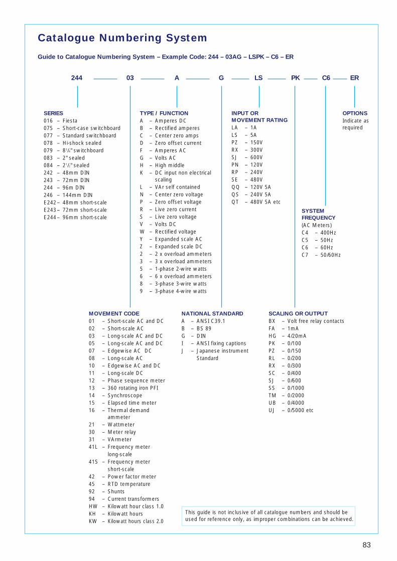
Guide to Catalogue Numbering System – Example Code: 244 – 03AG – LSPK – C6 – ER
MOVEMENT CODE
01 – Short-scale AC and DC02 – Short-scale AC03 – Long-scale AC and DC05 – Long-scale AC and DC07 – Edgewise AC DC08 – Long-scale AC10 – Edgewise AC and DC11 – Long-scale DC12 – Phase sequence meter13 – 360 rotating iron PFI14 – Synchroscope15 – Elapsed time meter16 – Thermal demand
ammeter21 – Wattmeter30 – Meter relay31 – VArmeter41L – Frequency meter
long-scale41S – Frequency meter
short-scale42 – Power factor meter45 – RTD temperature92 – Shunts94 – Current transformersHW – Kilowatt hour class 1.0KH – Kilowatt hoursKW – Kilowatt hours class 2.0
TYPE / FUNCTION
A – Amperes DCB – Rectified amperesC – Center zero ampsD – Zero offset currentF – Amperes ACG – Volts ACH – High middleK – DC input non electrical
scalingL – VAr self containedN – Center zero voltageP – Zero offset voltageR – Live zero currentS – Live zero voltageV – Volts DCW – Rectified voltageY – Expanded scale ACZ – Expanded scale DC2 – 2 x overload ammeters3 – 3 x overload ammeters5 – 1-phase 2-wire watts6 – 6 x overload ammeters8 – 3-phase 3-wire watts9 – 3-phase 4-wire watts
NATIONAL STANDARD
A – ANSI C39.1B – BS 89G – DINI – ANSI fixing captionsJ – Japanese instrument
MI Moving iron, also called ‘iron vane’ in the North American market for measuring AC amps and volts.
MC Moving coil for measuring DC amps and volts.
Taut band suspension A meter movement held under tension, usually on a ligament.movement
Ligament The taut band.
Pivot and jewell (P&J) A movement which rotates on a spindle, and pivots within an oil filled jewel. This type of movement typically offers excellent vibration resistance characteristics.
Short-scale Angle of deflection for a movement is usually 90 degrees but ANSI is 100 degrees in some products.
Long-scale Angle of deflection for a movement is usually 240 degrees but is frequently referred to as 270 degree.
FSD Full scale deflection.
ES End scale.
Input Electrical value from which the measurement is derived to achieve the full scale deflection of the movement.
Linear A term used to state that the input is constant, allowing for an even scaling.
Non linear The opposite of linear, giving a scale shape which will cramp at some point on the dial. Usually inaccurate below 20% of the full-scale value.
Logarithmic scaling A log scale usually derived from a non linear DC output.
Scale The graphical representation of the value being measured.
Dual arc More than one set of figures on a dial plate.
Dial plate/scale plate Surface on which the dial is drawn.
Calibration chart A chart matching input values to scale mark, mainly used for complicated scales.
Enclosure rating Usually expressed in the form of IP rating or as NEMA in America. This states the product, resistance to the ingress of moisture and dust.
DIN European standard meter shape. It is based on multiplies of 24mm, i.e. 48, 72, 96, 144 mm.
ANSI American National Instrument Standard.
JIS Japanese Instrument Standard.
BS89 Old British Standard usually refers to rectangular meter or “Fiesta” style products.
Switchboard meter General term for long-scale instruments.
Panel meter General name for short-scale instruments.
Analogue indicator Generic term for instruments usually refers to a low accuracy meter. An indicator only.
Analogue InstrumentsDIN Panel Meters
Page 1 of 2
Ref: DIN – Rev 1 – Sept 02
INSTALLATION INSTRUCTIONS
The product should be panel mounted using the mountinghardware supplied. Consideration should be given to thespace behind the unit to allow for bends in the connectingcables. The terminals on the meter rear should beprotected from liquids.
The unit must not be mounted where it can be subjectedto direct sunlight, and vibration should be kept to aminimum. Connection wires must be sized to comply withlocal regulations and must be terminated on tags suitablefor screw connection. The product has no internal fuse,therefore; external fuses must be used for safetyprotection under fault conditions.
SAFETY INSTALLATION FOR COMPLIANCE TOSAFTEY STANDARDS
WARNING
• During normal operation, voltages hazardous to lifemay be present at some of the terminals of this unit.Installation and servicing should be performed onlyby qualified, properly trained personnel' abiding bylocal regulations. Ensure all supplies are de-energised before attempting connection or otherprocedures.
• Terminals should not be user accessible afterinstallation and external installation provisions mustbe sufficient to prevent hazards under faultconditions.
• Never open circuit the secondary winding of anenergised current transformer.
SAFETY STANDARDS
This product complies with:International standard: IEC1010-1For UK: BS EN 61010-1 (IEC1010-1)
Fusing and connectionsThis unit must be fitted with external fuses in voltagesupply lines. Voltage input lines must be fused with aquick blow fuse 1A maximum. Choose fuses of a typeand with a breaking capacity appropriate to the supplyand in accordance with local regulations.
SAFETY SPECIFICATION
• Permanently connected use.• Normal condition• Basic insulation• Installation category II• Pollution degree 2• This product is intended as part of a permanent
installation.• Low Voltage Directive BSEN 61010-1• For use in altitudes up to 2000m• Temperature 0-40 degree C Maximum relative humidity
80% for temperature up to 31º C decreasing linearly to50% RH at 40ºC
• Operating temperature to retained stated productaccuracy 0-40ºC
Electromagnetic CompatibilityThis unit has been designed to provide protection against EM(electro-magnetic) interference in line with requirements ofEU and other regulations. Precautions necessary to provideproper operation of this and adjacent equipment will beinstallation dependent and so the following can only begeneral guidance:-• Avoid routing wiring to this unit alongside cables and
products that are, or could be, a source of interference.• The auxiliary supply to the unit should not be subject to
excessive interference. In some cases, a supply linefilter may be required.
• To protect the product against incorrect operation orpermanent damage, surge transients must be controlled.It is good EMC practice to suppress differential surges to2kV or less at the source. The unit has been designedto automatically recover from typical transients, howeverin extreme circumstances it may be necessary totemporarily disconnect the auxiliary supply for a periodof greater than 5 seconds to restore correct operation.
• Screened communication and small signal leads arerecommended and may be required. These and otherconnecting leads may require the fitting of RFsuppression components, such as ferrite absorbers, linefilters etc., if RF fields cause problems.It is good practice to install sensitive electronicinstruments that are performing critical functions in EMCenclosures that protect against electrical interferencecausing a disturbance in function.
The Information contained in these installation instructions is for use only by installers trained to make electrical power installations and is intended to describe thecorrect method of installation for this product. However, Tyco Electronics has no control over the field conditions, which influence product installation.It is the user's responsibility to determine the suitability of the installation method in the user's field conditions. Tyco Electronics' only obligations are those in TycoElectronics' standard Conditions of Sale for this product and in no case will Tyco Electronics be liable for any other incidental, indirect or consequential damagesarising from the use or misuse of the products. Crompton is a trademark.
Analogue InstrumentsDIN Panel Meters
Page 2 of 2
Ref: DIN – Rev 1 – Sept 02
INSTALLATION INSTRUCTIONS
D A B
48 x 48 45 x 45 4
72 x 72 68 x 68 4
96 x 96 92 x 92 4
144 x 144 135 x 135 4
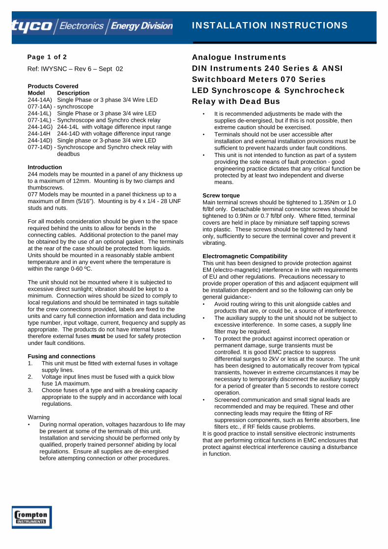
Analogue InstrumentsDIN Instruments 240 Series & ANSISwitchboard Meters 070 SeriesLED Synchroscope & SynchrocheckRelay with Dead Bus
Page 1 of 2
Ref: IWYSNC – Rev 6 – Sept 02
INSTALLATION INSTRUCTIONS
Products CoveredModel Description244-14A) Single Phase or 3 phase 3/4 Wire LED077-14A) - synchroscope244-14L) Single Phase or 3 phase 3/4 wire LED077-14L) - Synchroscope and Synchro check relay244-14G) 244-14L with voltage difference input range244-14H 244-14D with voltage difference input range244-14D) Single phase or 3-phase 3/4 wire LED077-14D) - Synchroscope and Synchro check relay with
deadbus
Introduction244 models may be mounted in a panel of any thickness upto a maximum of 12mm. Mounting is by two clamps andthumbscrews.077 Models may be mounted in a panel thickness up to amaximum of 8mm (5/16”). Mounting is by 4 x 1/4 - 28 UNFstuds and nuts.
For all models consideration should be given to the spacerequired behind the units to allow for bends in theconnecting cables. Additional protection to the panel maybe obtained by the use of an optional gasket. The terminalsat the rear of the case should be protected from liquids.Units should be mounted in a reasonably stable ambienttemperature and in any event where the temperature iswithin the range 0-60 ºC.
The unit should not be mounted where it is subjected toexcessive direct sunlight; vibration should be kept to aminimum. Connection wires should be sized to comply tolocal regulations and should be terminated in tags suitablefor the crew connections provided, labels are fixed to theunits and carry full connection information and data includingtype number, input voltage, current, frequency and supply asappropriate. The products do not have internal fusestherefore external fuses must be used for safety protectionunder fault conditions.
Fusing and connections1. This unit must be fitted with external fuses in voltage
supply lines.2. Voltage input lines must be fused with a quick blow
fuse 1A maximum.3. Choose fuses of a type and with a breaking capacity
appropriate to the supply and in accordance with localregulations.
Warning• During normal operation, voltages hazardous to life may
be present at some of the terminals of this unit.Installation and servicing should be performed only byqualified, properly trained personnel' abiding by localregulations. Ensure all supplies are de-energisedbefore attempting connection or other procedures.
• It is recommended adjustments be made with thesupplies de-energised, but if this is not possible, thenextreme caution should be exercised.
• Terminals should not be user accessible afterinstallation and external installation provisions must besufficient to prevent hazards under fault conditions.
• This unit is not intended to function as part of a systemproviding the sole means of fault protection - goodengineering practice dictates that any critical function beprotected by at least two independent and diversemeans.
Screw torqueMain terminal screws should be tightened to 1.35Nm or 1.0ft/lbf only. Detachable terminal connector screws should betightened to 0.9Nm or 0.7 ft/lbf only. Where fitted, terminalcovers are held in place by miniature self tapping screwsinto plastic. These screws should be tightened by handonly, sufficiently to secure the terminal cover and prevent itvibrating.
Electromagnetic CompatibilityThis unit has been designed to provide protection againstEM (electro-magnetic) interference in line with requirementsof EU and other regulations. Precautions necessary toprovide proper operation of this and adjacent equipment willbe installation dependent and so the following can only begeneral guidance:-• Avoid routing wiring to this unit alongside cables and
products that are, or could be, a source of interference.• The auxiliary supply to the unit should not be subject to
excessive interference. In some cases, a supply linefilter may be required.
• To protect the product against incorrect operation orpermanent damage, surge transients must becontrolled. It is good EMC practice to suppressdifferential surges to 2kV or less at the source. The unithas been designed to automatically recover from typicaltransients, however in extreme circumstances it may benecessary to temporarily disconnect the auxiliary supplyfor a period of greater than 5 seconds to restore correctoperation.
• Screened communication and small signal leads arerecommended and may be required. These and otherconnecting leads may require the fitting of RFsuppression components, such as ferrite absorbers, linefilters etc., if RF fields cause problems.
It is good practice to install sensitive electronic instrumentsthat are performing critical functions in EMC enclosures thatprotect against electrical interference causing a disturbancein function.
The Information contained in these installation instructions is for use only by installers trained to make electrical power installations and is intended to describe thecorrect method of installation for this product. However, Tyco Electronics has no control over the field conditions, which influence product installation.It is the user's responsibility to determine the suitability of the installation method in the user's field conditions. Tyco Electronics' only obligations are those in TycoElectronics' standard Conditions of Sale for this product and in no case will Tyco Electronics be liable for any other incidental, indirect or consequential damagesarising from the use or misuse of the products. Crompton is a trademark.
Analogue InstrumentsDIN Instruments 240 Series & ANSISwitchboard Meters 070 SeriesLED Synchroscope & SynchrocheckRelay with Dead Bus
Page 2 of 2
Ref: IWYSNC – Rev 6 – Sept 02
INSTALLATION INSTRUCTIONS
Setting Up and MaintenanceUnits are adjusted before despatch and therefore noadjustments are required. Unless a fault develops, the unitrequires little attention. During routine servicing andinspection of the associated equipment, the unit should beinspected to normal standards for this class of equipment.For example remove accumulations of dust and check allconnections for tightness and corrosion. In the event of arepair being necessary, it is recommended that the unit bereturned to the factory or to the nearest CromptonInstruments Service Centre, (details on page 2). Shouldrepair be attempted then replacement components must beof the same type, rating and tolerance as those used in theoriginal circuit. It is important that should calibration bedeemed necessary, say after repair, then this should only beattempted if the required high accuracy equipment isavailable. With any enquiry please quote the full modelnumber found on the side of the label. The unit must berecalibrated after repair.
The operation as a SynchroscopeThe 244-14A and 077-14A synchrocopes provide illuminatedindication of the actual phase difference between thegenerator GEN voltages and the busbar voltage. If the LEDdisplay rotates clockwise the generator frequency is too highand must be reduced and visa versa if the LED display turnsanticlockwise.
The operation as synchrocheck relayThe 244-14L/G and 077-14L synchroscopes are based on amicrocontroller, which interprets the input signals anddisplays the phase and voltage information on a series oflight emitting diodes (LED’s).
Twenty four red LED’s are arranged in a ring simulating thetraditional 360° analogue movement. Only one LED is lit atany one time indicating the phase difference between thebusbar (BUS) and generator (GEN) signals. The unit willoperate correctly at any frequency within its range.The voltage levels of the two input signals are continuouslymeasured and compared with the user adjustable voltagedifference setting. If the measured difference is outside theallowable range, the ring of LED’s will be extinguished andthe red GEN LED will be lit. If the voltage difference is withinrange the green GEN LED will be lit and the ring of LED’swill indicate the phase relationship.Once the BUS and GEN signals become coincident, the unitwill wait for an adjustable time delay before lighting thegreen triangular SYNCHRONISED LEDS and operating therelay. The ring of LED is also extinguished which means theuser will only see green LED’s when the generator GEN issynchronised with the BUS.The rear pot adjustments should be set to suit operationalrequirements.
The Operation as Synchro Check Relay with Dead Bus
The 244-14D/H and 077-14D operate in the same way asthe 244-14L and 077-14L Synchro check relays with theaddition of a dead bus option. This optional feature enablesthe relay to energise with a GEN supply only thus allowingthe generator to power the BUS during a supply failure.
Connection Diagrams
Model 244-14A 360° LED Synchroscope & Models 244-14L/D/G/H 360 LED Synchroscope and Synchro Checkrelay
Relay RatingsSingle pole changeover 250V, 5A a.c. resistive.
Model 077-14A 360° LED Synchroscope & 360 LEDSynchroscope and Synchro Check Relay Models 077-14L/D/G/H
INSTALLATION INSTRUCTIONS
NC = Normally closedCO = CommonNO = Normally open
Terminals 1,3 & 4 are not usedon Model 244-14A.
‘GEN’L1 L2 L3
‘BUS’L1 L2 L3
Terminals 3, 10 and 12 are notused on Model 077-14A.