TABLE OF CONTENTS SPECIAL NOTICE AND CALIFORNIA PROPOSITION 65 WARNING 3
CUSTOMER GREETING AND EXPLANATION OF PROCEDURES 4
WARRANTY AND CONTACT INFORMATION 5
SAFETY DISCLAIMER AND HF WARNING 6
SAFETY WARNINGS, DANGERS, CAUTIONS AND INSTRUCTIONS 7
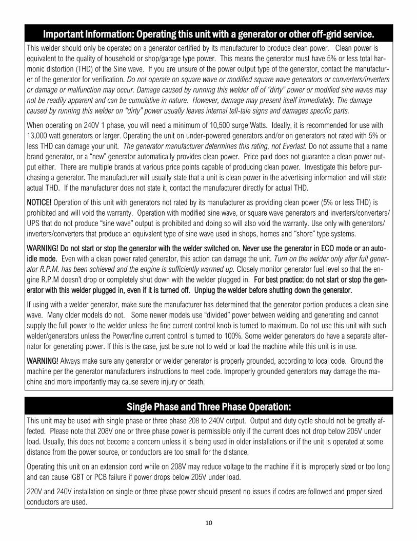
GENERATOR OPERATION INFORMATION 10
SPECIFICATIONS, INCLUDING DUTY CYCLE AND INPUT AMPERAGE INFORMATION 11
GETTING STARTED, UNPACKING YOUR UNIT AND INSPECTION 12
CONNECTING YOUR UNIT TO THE POWER SOURCE AND WIRING INFORMATION 13
SHIELDING GAS INFORMATION AND CONNECTION OF REGULATOR 14
TUNGSEN SELECTION AND GRINDING 15
CONNECTING YOUR UNIT AND READYING TO WELD (POLARITY AND PANEL CONNECTIONS) 18
GENERAL SETTINGS AND INFORMATION 20
FRONT PANEL VIEW AND COMPONENT ID 21
REAR PANEL VIEW AND COMPONENT ID 22
CONTROL PANEL LAYOUT AND ID OF FEATURES 23
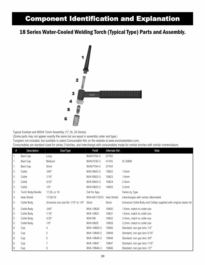
TORCH PARTS AND ASSEMBLY 30
7 PIN CONNECTOR PINOUT AND INFORMATION 31
TROUBLESHOOTING ERROR CODES 32
TROUBLESHOOTING COMMON ISSUES 33
MAINTENANCE 34
3
NOTICE:
Product Specifications and features are subject to change without notice. While
every attempt has been made to provide the most accurate and current infor-
mation possible at the time of publication, this manual is intended to be a general
guide and not intended to be exhaustive in its content regarding safety, welding,
or the operation/maintenance of this unit. Due to multiple variables that exist in
the welding field and the changing nature of it and of the Everlast product line,
Everlast Power Equipment INC. does not guarantee the accuracy, completeness,
authority or authenticity of the information contained within this manual or of any
information offered during the course of conversation or business by any Everlast
employee or subsidiary. The owner of this product assumes all liability for its use
and maintenance. Everlast Power Equipment INC. does not warrant this product
or this document for fitness for any particular purpose, for performance/accuracy
or for suitability of application. Furthermore, Everlast Power Equipment INC. does
not accept liability for injury or damages, consequential or incidental, resulting
from the use of this product or resulting from the content found in this document
or accept claims by a third party of such liability.
WARNING!
California Proposition 65 Warning:
This product, when used for welding or cutting, produces fumes or gases which contain chemicals known to the State of California to cause birth defects and, in some cases, cancer. (California Health & Safety Code § 25249.5 et seq.)
Warning: Cancer and/or Reproductive Harm
www.P65warnings.ca.gov
4
THANK YOU! We appreciate you as a valued customer and hope that you will enjoy years of use from your welder. We work to please the customer by
providing a well supported, quality product. To make sure that you receive the best quality ownership experience, please see below for important infor-
mation and time sensitive details.
What to do right now:
1. Print your receipt from your confirmation email that should have been sent to you after your purchase and put it up for safe keeping. If you do not
have one, contact us at 1-877-755-9353 (US customers) or 1-905-570-1818 (Canadian Customers). You will need this if anything should ever
happen for original owner verification (if bought as a gift, original receipt will still be needed, or explanation sent to Everlast).
2. Read this manual! A large number of tech and service calls are a result of not reading the manual from start to finish. Do not just scan or casually
peruse this manual. There are different features and functions that you may not be familiar with, or that may operate differently than you expect.
Even if you have expertise in the field of welding, you should not assume this unit operates like other brands or models you have used.
3. Carefully unpack and inspect all items immediately. Look for missing or damaged items. Please report any issues within 48 hours (72 hours on
weekend or holidays) of receiving your product,. Take pictures if you are able and contact us at 1-877-755-9353, ext. 207 if any issue is discov-
ered between 9 am and 5 pm Eastern Time M-F (US customers) or at 1-905-570-1818 (Canadian Customers) between 9am and 4 pm weekdays
except on Fridays when hours are from 9 am to 12pm Eastern. If outside of the US or Canada, contact your in-country/or regional distributor di-
rect at their service number.
What to do within the next 2-3 days:
1. Make sure your electrical system is up to date and capable of handling the inrush and rated current of the unit. Consult and use a licensed and
knowledgeable electrician. If you have downloaded this manual in expectation of delivery, get started now.
2. Make sure this machine is plugged in, turned on, and tested with every process and major feature, checking for proper function. You have a 30
day period to test and thoroughly check out the operation of this unit under our 30 day satisfaction period. If something is wrong, this policy co-
vers shipping on the unit (30 day satisfaction policy applies to the USA only for the 48 lower states and D.C., territories and provinces are exclud-
ed) or any incidental parts that may be needed to resolve any issue. After this 30 day period, if you find something wrong with the unit, you will not
receive the benefit of free shipping back and forth to resolve this issue. Your unit is still covered under the 5 year parts/labor warranty, but ship-
ping is covered by the customer after the 30 day period is over. The first 30 days of operation with any electronic item is the most critical and if
any issue will happen, it will often happen during this time. This is why it is very important that you put this unit to work as soon as possible. Any
issue should be reported within 48 hours (72 if on the weekend or holiday). Everlast will not be liable for any shipping after that time.
What to do within the next 30 days:
Visit our website (US customers). Go to www.everlastwelders.com. Navigate to the resources tab and to the “product registration” page to register
your product. While keeping your receipt/proof of purpose is still required for verification of ownership, registering will help us keep your details
straight and establish a chain of ownership. Don’t worry, though, your warranty is still valid if you can’t do this. Remember: Always keep your receipt
even if you register. You may want to staple a copy to your manual.
What to do if you have a warranty issue or problem with the unit:
1. Unplug the unit. (Also do this before any maintenance or cleaning is done.)
2. Do not attempt a self-repair until authorized by an Everlast representative. This does not include performing routine maintenance such as point gap
adjustments or regular internal cleaning. Any third party repairs are not covered under warranty, and can further damage your unit.
3. Within 24-48hours, (or by the next working business day) you must contact U.S. tech support at 1-877-755-9353 ext 207(U.S. hours are 9 am to
5pm Eastern for tech support and 9 am to 5 pm Pacific for the business/sales office). If you are in Canada contact 1-905-570-1818 (Canada hours
are 9am to 4pm M-Th, 9am to 12pm Fri). Although phone contact is preferred to establish a warranty claim, you may send an email to
ask for a follow up call. If you contact us via phone, and you do not reach a live person, please leave a brief message with the nature of your prob-
lem and your contact information. You should expect a call back within 24 hours. It is also a good idea to follow up the message with an email.
4. Be prepared with as much information as possible when you talk with a tech advisor, including a details of the failure, settings, and application of
the unit. NOTE: A Proof-Of-Purchase (receipt) is required before returning the unit for warranty or before warranty parts can be sent to you.
5. Keep in mind that, you may be asked to check a few basic things. Before you call, having a screwdriver and volt/ohm meter at hand is a good idea
and will save time. Many issues can be resolved over the phone. If the issue cannot be resolved over the phone/email, you may be given an op-
tion to return the unit, or have a part shipped to you, at Everlast’s discretion. Keep in mind, you may be asked questions that seem basic, or ele-
mentary to your knowledge base. These are not meant to question your knowledge, but rather to make sure nothing is overlooked. However the
tech chooses to proceed, please cooperate with the process, even if you think you know what the cause or issue is. You may be asked to check
something or open the unit during the diagnosis. This does not void the warranty! Opening the unit is a part of routine maintenance and cleaning.
This is an important step. The willingness of the customer to work with tech support can save lots of time and accelerate the warranty process. For
5
warranty to be honored, you will need to make sure that you follow these guidelines. Units that are returned without an RMA (issued by the tech
support department) may not be repaired under the warranty agreement and you may be charged for the repair and can result in a delayed repair
as well.
What to do if you need setup help, guidance, weld issue diagnosis or have general product compatibility questions.
Call us at 877-755-9353 ext. 204 for welding guidance and general welding issue diagnosis. Or email [email protected] with the basic
issue you are having, along with your specific settings, and welding application.
Hey...wait, what is my warranty?
Warranties and service policies and procedures vary from country to country and are maintained and supported by the region-
al or in country distributor of Everlast welding equipment.
USA Customers Only: For full details on the 5 year parts and labor warranty, 30 day satisfaction policy, terms of sale, and how to proceed with a war-
ranty claim, please visit: https://www.everlastgenerators.com/standard-warranty. Accessories are covered by a separate warranty and detailed infor-
mation can also be found at the link above.
Canada Customers Only: For full details on the 3 year parts and labor warranty, terms of sale, and related policies and procedures, please visit: https://
USA Welding Support and General Product Information: Email: [email protected] 1-877-755-9353 ext 204 9am-6:30 pm Eastern (Closed holidays) Monday-Friday
USA Sales and Main Office: Email: [email protected] 1-877-755-9353 ext 201 9am-5pm Pacific (Closed holidays) Monday-Friday
Canada Sales and Main Office: Email: [email protected] 905-570-1818 9am-4pm Eastern Monday-Thursday 9am-12pm Eastern Friday
Other Countries and Regions: Visit the U.S. Website @ www.everlastwelders.com and click on the flag of the country or region represented that is closest to you. If your country or region is not found, call the U.S. office at 1-650-588-8588 between the hours of 9am to 5pm Pacific, Monday through Friday.
6
Safe operation and proper maintenance is your responsibility.
Everlast is dedicated to keeping safety a top priority. While we have compiled this operator’s manual to instruct you in basic safe operation and maintenance of your Everlast product, it is no substitute for observing safe welding practices and behavior. Safe welding and related cutting operations require basic knowledge, experience and ultimately the exercise of common sense. Welding does significant hazards to your health and life! Exercise extreme caution and care in all activities related to welding or cutting. Your safety, health and even life depends upon it.
WARNING! If you do not have proper knowledge or capability to safely operate this machine, do not use this machine until proper training has been received!
While accidents are never planned, preventing an accident requires careful planning. Stay alert!
Please carefully read this manual before you operate your Everlast unit.
The warranty does not cover damage or harm created by improper use. neglect of the machine or failure to follow safe operating practices.
NOTICE:
Welding and cutting operations may generate undesirable High Frequency (HF) and EMF
energy. This can interfere with surrounding electronic equipment such as computers,
routers, CNC equipment, televisions, radios, fluorescent lighting etc. If disturbance in
surrounding electrical and electronic equipment is noted, consult a licensed electrician to
help properly ground surrounding equipment to limit the interference. This machine may
cause GCFI and ground fault outlets to malfunction. This unit is designed to be operated
on a dedicated, properly grounded circuit.
7
Safety Warnings, Dangers, Cautions and Instructions
NOTICE. This unit manual is intended for users with basic knowledge and skillset in weld-
ing. It is your responsibility to make certain that the use of this welder is restricted to per-
sons who have read, understand and follow the warnings and instructions in this manual. If
you or the operator needs further instruction, contact Everlast welding support at 1-877
755-9353 ext. 204 or seek qualified professional advice and training.
WARNING! High Frequency (HF) energy can interfere with the operation of pacemakers
and can damage pacemakers. Consult with your physician and pacemaker manufacturer
before entering an area where welding and cutting equipment is in operation and before
using this welder. Some pacemakers have limited shielding. Alert any users or customers
of this potential problem.
WARNING! Use approved safety glasses with wrap around shields and sides while welding
and working in the weld area or serious eye damage or loss of vision may result. Use a
grinding shield in addition to the safety glasses during chipping and grinding operations.
WARNING! When welding always use an approved welding helmet or shielding device
equipped with at least an equivalent of a shade 9 or greater. Increase the shade number
rating as amperage increase over 100 amps. Inspect helmet for cracks in lenses and in the
helmet. Keep lens covers in good condition and replace as necessary.
WARNING! Welding/cutting operations carry inherent risks which include but not limited to
possible cuts burns, electrical shocks, lung damage, eye damage and even death. Take all
appropriate measures to use proper Personal Protective Equipment (PPE). Always use
leather welding gloves, closed toe (preferably reinforced or steel toe leather shoes, and
long-sleeved flame resistant clothing (i.e. denim). Do not wear Poly/Nylon blend materials.
DANGER! Welding poses shock and electrocution risks. Keep this welding equipment dry.
Do not weld in the rain or where moisture accumulates. Use dry, rubber soled shoes,
gloves and clothing when welding. Do not rest or contact work clamp (ground) when weld-
ing. Keep all parts of the body insulated from the part being welded when possible. Do
not touch both terminals or connections at the same time. Consider all welder parts to be
“live” at all times even if no welding is being performed. Do not use frayed welding cables.
CAUTION! Fires are possible but also preventable while welding. Always remove flamma-
ble rags, papers, and other materials from the weld area. Keep rags stored in an approved
flame proof canister. Keep a fully charged fire extinguisher at hand. Remove any fuels,
oils, paint, pressurized spray cans, and chemicals from the weld area. Make sure any
smoke/fire detectors are function properly. Do not weld on tanks, drums or barrels, espe-
cially if pressurized or sealed. Do not weld on any container that previously held fuel or
chemicals. Make sure the weld area is clear of flammable materials such as grass or wood
shavings solvents and fuels. Do not wear frayed or loose clothing. Visually inspect and
recheck the work area after welding looking for smoldering debris or flames.
WARNING! Welding gas cylinders are under high pressure. Keep all gas cylinders upright
and chained to a cart or held safely in a safety holding pen. Never transport gas cylinders
in an enclosed car van or other vehicle. Transport gas cylinders securely. Keep all cylin-
ders capped while not in use or during transport. Replace the cap on the cylinder when it
is going to be more than 24 hours before use. Do not use or attempt to repair faulty regu-
lators. Never weld on gas cylinders. Keep gas cylinders away from direct sparks.
8
Safety Warnings, Dangers, Cautions and Instructions DANGER! Welding and cutting operations pose serious inhalation hazards. Some of these
hazards are immediate while others are cumulative in their effect. Do not weld in enclosed
spaces or in areas without adequate ventilation. Fumes and gases released in the welding
and cutting operations can be toxic. Use fans or respiration equipment to insure adequate
ventilation if you are welding in a shop or garage area. Do not weld on galvanized metal
under any circumstance. You may develop metal fume fever. Symptoms are similar to lu-
like symptoms. Seek medical advice and treatment if you are exposed to galvanized weld-
ing fumes.
If you experience any eye burning, nose or throat irritation while welding, these are signs
that you need more ventilation.
If you feel these symptoms:
• Stop work immediately and relocate work area with better ventilation.
• Wash and clean your face and hands.
• Stop work completely and seek medical help if irritation persists
DANGER! Never use brake cleaner or any chlorinated solvent to clean or degrease metal
scheduled to be welded or other related equipment in the area being welded. The heating
of this cleaner and its residue will create highly toxic phosgene gas. Small amounts of
this vapor are harmful and can lead to organ failure and death. If degreasing of a part is
necessary, use Acetone or an approved pre-weld cleaner. Use the proper personal protec-
tive equipment (PPE) when handling any cleaners/solvents.
DANGER! People with pacemakers should consult a physician and pacemaker manufactur-
er before welding. There is a potential for damage or serious malfunction resulting in
death. High Frequency energy (HF)/Electromagnetic Fields generated during welding can
interfere with pacemaker signals, even permanently damaging it. Some pacemakers offer
some shielding, but restrictions regarding amperage and HF starting of TIG arcs may be
placed upon the individual. Warn all potential bystanders that they should exit the work
area if they have a pacemaker or similar medical equipment before welding. Consult with a
Physician if a pacemaker is expected to be implanted.
DANGER! Never defeat or modify any safety guards or shields. Keep all safety covers and
shields in place.
Never place your fingers in or near a fan shroud or insert any object into the fan(s).
9
Safety Warnings, Dangers, Cautions and Instructions CAUTION! Trip Hazards exist around welders. Cords, cables, welding leads and hoses pose
a trip hazard. Be aware of their location and inform others of their location. Tape and se-
cure them so they will stay out of high traffic areas.
CAUTION! Welded metal can stay hot long after welding is completed. Burns may occur.
Always wear gloves or use tongs/pliers when handling welded or cut metal. Remember
the heat from the metal may catch other material on fire. Always have a fire-proof area
ready to place welded components until they fully cool. Use soap stone or a metal marking
marker to label the metal as “HOT” to serve as a reminder to all present in the area.
CAUTION! Welding and cutting operations generate high levels of ultraviolet (UV) radiation
which can burn and damage skin and eyes. The intensity is so high that exposed skin and
eyes can burn in a few minutes of exposure. Minimize direct skin and eye exposure to this
intense form of radiation by using proper PPE and sun screen where appropriate.
CAUTION! Do not allow bystanders. Do not allow others without proper Personal Protec-
tion Equipment (PPE) suitable for welding to stand in the welding area or to observe weld-
ing and welding related activities. If protection is not readily available, use a welding
screen to separate the welding area from the rest of the area. If no protection or screen is
available, physically exclude them from the welding area by a wall or other solid divider.
Keep all pets and young children away from the welding area.
CAUTION! Electromagnetic Fields can be generated by this welder and radiate into the work
place. The effect of EMF is not fully known. Exercise caution when welding by: NOT drap-
ing welding leads (guns/cables) over your shoulders or arms, NOT coiling them around
your body, NOT inserting yourself directly between the cables, and by NOT contacting the
unit while welding. DO keep the work clamp connected as close as possible to the area of
the weld and directly to the object being welded whenever possible.
Recommended Power Plug Type for Single Phase Operation NEMA 6-50P (Standard 240V Welder Type)
Cooling Type Full Time, High Volume Fan(s)
Dimensions (Approximate) 18” H X 10” W X 25” L
Weight (Bare Unit) 65lbs.
Ingress Protection Rating IP21S
*Duty Cycle
Duty Cycle is simply the amount of time out of a 10
minute period in which the unit can operate. For
example, if this unit has a duty cycle of 60%, that
means that the unit can be operated for 6 minutes
out of 10 minutes. This may be continuously, or
intermittently during the 10 minute period of time.
This rating standard (United States) is based on a
maximum ambient temperature of 40 C. Operating
above this point, or at lower temperatures with high
humidity may reduce the duty cycle rating. Of
course, the duty cycle may increase somewhat as
ambient temperature drops. Regardless, this unit
does not limit duty cycle based off of a timer. Rather,
this unit is equipped with a heat sensor located on a
heat sink near the critical power components of the
welder. If the operating temperature of the unit is
exceeded, welding output will stop and an over-
temperature warning light/error code will be dis-
played on the panel. If a duty cycle event is regis-
tered, do not turn the unit off! Allow the welder to
continue to run at idle for at least 10-15 minutes until
the temperature has fallen enough to reset the sensor
and over-temperature warning light. Even if the unit
resets, allow the unit to cool for a full 15 minutes, or
the duty cycle will be more quickly triggered since
the unit resets just below the heat threshold. The fan
(s) must continue to run for a full 15 minutes to cool
the unit properly after the duty cycle shut down has
occurred. After 15 minutes of cooling, you may
switch the unit off if you are finished welding. If the
unit does not automatically reset after 15 minutes,
turn the unit off. Wait for 15 seconds before turning
the machine back on. If the unit does not reset,
contact technical support for further advice and as-
sistance. As a best practice, when you have complet-
ed welding and have been welding continuously for
extended periods of time, keep your unit on for 10
additional minutes without welding to allow it to cool.
The intentional and/or repeated triggering of the duty
cycle protection feature on this unit will shorten the
lifespan of the unit’s electronics and can weaken
internal components. The effect of overheating your
unit repeatedly takes a cumulative toll on the unit.
Breaker Sizing and Wiring Requirements
Before installation of this unit in any facility, always consult a licensed local electrician familiar with the requirements of properly wiring a welder into the electrical sup-
ply. Refer to the National Electric Code (NEC) and local codes. If needed, refer the electrician to Article 630 of the NEC during consultation to determine proper applica-
tion and wiring needs. Use the I1MAX and the I1EFF ratings listed above to determine the proper breaker and conductor (wire) sizing required. Everlast welders are de-
signed around use in industrial wiring applications and are intended to be used with modern electrical systems. Household wiring may need to be upgraded before this
welder may be installed. Additional HF protection and isolation may be needed if this welder interferes with the operation of electrical/electronic equipment. WARNING!
12
Setup Guide
Getting Started
UNPACK YOUR UNIT.
Upon arrival, you will need to completely unpack your unit, and
check things over. This is a time sensitive matter. Do not delay or
hold the welder unopened in the box. First, make sure the unit is
opened from the top. Be careful with using knives and sharp objects
so you won’t cut cords and cables inside the boxes. Lay all items out
and inspect them.
You should have the following in your box:
1. Welder 2. Foot Pedal (Deluxe Style Standard, NOVA Style Optional) 3. Floating Ball Type Brass Argon Regulator with Tubing 4. 18 Series Water-Cooled Torch (Rigid/Straight Neck) 12.5 ft. 5. Torch Switch (Usually attached to torch) for 2T/4T operation 6. 250A Stick Electrode Holder (approx. 9.5 ft with cable) 7. 300A Work Clamp (approx. 9.5 ft with cable) 8. TIG Consumable Starter Kit (No Tungsten)
Inspect the welder for damage. Check for the presence and general condition of the accessories. Some slight rubbing or chaffing of some of the accessories may be present, but this is considered nor-mal. If any item is damaged or missing, please inform Everlast within 72 hours of product receipt. See pages 4 and 5 for more details. Assemble the front, middle and rear handles with the supplied screws. Do not overtighten the screws.
POWER UP AND TEST YOUR UNIT.
You will need to fully test the unit as soon as possible. Within 72
hours after receipt of the unit, be sure to have every thing you need
at hand to test the unit. Make sure the correct input power, wiring,
and plug configuration is being used. Then, power up your machine
without any accessories installed. Allow the unit to idle for 15
minutes. Check and observe operation of knobs, controls and but-
tons, cycling through each as required. Make sure the fan is running
1
2 3
4
5
6
8 7
NOTICE:
The foot pedal may arrive with the top separated from the bottom. This
is not damage. The top can easily be installed on the bottom, by align-
ing the pivot pins with the corresponding holes for the pins located in
the top. The pins are spring loaded and can be squeezed so that the top
slides down onto the pins. The pins will pop out into the holes and
allow the top to pivot once the pins and holes are properly aligned.
You may need to make sure the pressure return spring is flipped so that
it pushes back against the pedal as it is assembled. Similarly, the foot
pedal may be disassembled simply by pressing in on the ends of the
pins on both sides to remove the top.
at full speed. After the test is completed, turn the unit off, connect
the accessories, shielding gas (customer supplied) and conduct live
testing of all the functions and features of the machine. For testing
and welding make sure work clamp is connected directly to the part
being welded (work). Check for arc starting and stability. If prob-
lems are observed, contact Everlast. See page 5 for more infor-
mation. NOTICE: Cosmetic damage claims after 30 days will not be
accepted, unless a Everlast is contacted and informed of such delay
and reason for such a required delay (ie. Overseas in deployment
etc.)
CHECK FOR GAS LEAKS.
Be sure to check for gas leaks before attempting to weld. You can
test this by first installing both back caps into the torch head (from
both sides). Next install the regulator and tighten to both cylinder
and unit (see section on regulator installation). After the regulator is
secured, set post flow time to maximum. Trigger a false start with
either the foot pedal or torch switch by tapping and releasing so that
post flow can flow. Observe the ball on the regulator. It will briefly
float before settling back down. If the ball continues to flow, or if you
hear or suspect leaks, use warm, soapy water (or a dedicated leak
testing solution available from welding suppliers) and spray on all
connections, including the torch connections at the head and handle.
If any leaks are present, bubbles will form around the area of the
leak. Tighten any clamps or fittings found to be leaking. If the prob-
lem cannot be remedied, contact Everlast.
DISTANCE YOUR WELDER FROM YOUR WORK.
As a best practice technique, be sure to locate your welder away from
the immediate area you are welding. The fan(s) found in your unit
are powerful enough to create strong air turbulence in the weld area.
This will disrupt the smooth, even flow of shielding gas around your
weld creating unstable arcs, porous welds, and dull finish on the
weld. If possible the welder should be located at least 6 feet away
from the weld area and should be on a different level to prevent weld
porosity and defects being created by the welder’s fan system. Keep
in mind the fan draws air in from the rear and exhausts out the front
and the sides of the unit. This information also pertains to the water-
cooler, if used.
GIVE YOUR WELDER SPACE TO COOL.
The welder needs room to cool itself. Place the unit in a place that
will allow 18” from all sides to allow for proper cooling. The welder
pulls air in from the rear, and pushes it through the unit’s heat sinks
to cool the electronics. The air is then exhausted through the front
panel and side louvers of the unit. If any of sides is blocked or re-
stricted, the duty cycle will be reduced, and overheating will occur,
leading to possible damage if the restriction is severe enough. Never
attempt to restrict air flow by attaching filters to the vents or by modi-
fying your fans for “on demand” service.
13
Setup Guide
Getting Started
CONNECT YOUR UNIT TO THE OUTLET.
You’ll notice that your unit has been shipped without a power plug. This is because the welder will operate on either single phase or three phase 240V voltage and the wiring is different for single phase service than it is for three phase service. You’ll also notice that this unit is equipped with 4 wires. The 4 wire configuration is not used with single phase 240V operation. Only 3 wires are used (black, white, and green in color). The remaining fourth wire (red color) is to either to be snipped off and taped over with electrical tape, or it is to
NOTICE: There are special rules centered around wiring an outlet for service
with a welding machine. The National Electric Code under Article
630 has developed specific regulations for wiring electrical service
for welding equipment. These are different than for other types of
service such as a stove or dryer in a household or even in a com-
mercial application. You need to consult and/or employ a locally
licensed electrician before installing this unit to make sure all nation-
al and local codes are followed. If you are not qualified to make
these connections, don’t. Everlast is in no way liable for any damag-
es caused by improper connection of your welder. Your welder
should be on a dedicated branch circuit not far from an electrical
disconnect box. Importantly, it should not share circuits with other
shop or household items. Do not attempt to “adapt” existing circuits
because conductor (wire) colors are different for welders with 3 wire
operation than for a dryer or range with 4 wire operation. (Unless
adapting with an approved adapter when being powered with a
“clean power” generator.) No neutral is used in a welder circuit. The
white wire is a conductor in a single phase welder service. The red
wire is not used. The input power cable conforms to North American
standards for size, length, with consideration given to inrush amper-
age, rated amperage and duty cycle. Do not modify, or attempt to
be bent back, and taped against the cable sheathing (if used inter-changeably between single and three phase service). For single phase 240V connection, select a NEMA 6-50 Plug and Receptacle for operation. This is the standard plug used when wiring welders for 240V single phase operation in North America. (Other regions/countries vary). A neutral is not used. If you inspect the NEMA 6-50 Plug closely (most brands) that the plug is stamped where each color wire should go. If you do not see a stamp, the Black wire serves as L1(Hot), White serves as L2 (Hot) and Green serves as G (Ground). For three phase 240V service, the plug configuration is different for various applications. It is recommended to either install the line direct into an electrical cutoff box, or wire a 3 phase receptacle and cutoff (disconnect) close to where the unit will be in use.
Wire Configuration 1 Phase 240V
.
NEMA 6-50P
Wire Configuration 3 Phase 240V
Selecting A Breaker and Wire Size Select a breaker based off of the I1MAX rating of this unit. This is the
maximum inrush current of the unit. The inrush is not a sustained
current. The I1EFF rating of the unit is the maximum “rated” current of
the machine. When combined with the length of the run from the
main panel, his determines the conductor size needed to supply the
welder, Refer your electrician to Article 630 and the specification
page of this manual (or the specification grid printed on your unit)
when selecting the correct breaker and wire size. A delayed trip
breaker, or slow blow fuse should be used with this unit.
Using with 208V 1 or 3 Phase This unit may be operated with 208V service (1 or 3 phase). How-
ever voltage should be checked under load before allowing perma-
nent installation. Voltage should not fall below 205V or damage may
occur to the unit. Most modern 208V service runs several volts
above 208V and is not usually a concern. Older installations where
service wiring may be degraded or not up to code may produce sub
standard voltage not suitable for use with this unit. Additionally,
some accuracy/calibration issues may be observed while on 208V.
14
Setup Guide
Getting Started
CONNECT YOUR UNIT TO THE SHIELDING GAS.
Always wear safety glasses when changing a cylinder. Before in-
stalling any cylinder, stand to the site of the valve, away from the
discharge, and quickly open the cylinder to give it a quick blast. This
will dislodge any dirt or particles stuck in the valve or the connection
seat. This will help reduce the chance of dirt particles making its way
into the solenoid valve, causing sticking issues later on.
Connecting your cylinder will require a cylinder wrench(1 1/16”)to
connect the regulator to the cylinder (North American Cylinders with
What Shielding Gas Should Be Used? Selecting shielding gas for MIG is straightforward. For all metals,
whether using in AC or DC, use 100% Argon. Never use a gas mix
mixed with CO2. CO2 will rapidly consume the tungsten and intro-
duce porosity into the weld even at low concentrations.
With that said, if you are welding at or near the maximum capability
of the unit, you may also wish to use an Argon/Helium mix. This
will increase the overall heat going into the weld. No more than
25% Helium mix should be used with this unit, or Arc starting effi-
ciency will be reduced (hard to start arc). Arc stability will also be
affected at higher percentages. Helium is expensive and the cost
versus benefit of adding it must be weighed carefully as a cylinder or
two of high percentage Helium may approach the cost difference of
upgrading to a larger unit! If a high Helium content is used, expect
some trade-offs. Arc starting may be improved slightly by readjust-
ing the point gap.
There are a few new gas mixes (blends) on the market with promise,
but as of publication they have not been thoroughly evaluated for
use with this welder. Exercise caution when using a new mixture
(often marketed with Nitrogen or Hydrogen) as the application is very
specific. Pure 100% Argon is the most economical and best for
nearly every application, and having multiple gases should not be a
concern for even the most advanced user.
BE AWARE: It is increasingly common for users to get cylinders of
“bad gas,” creating mysterious and difficult to identify issues. An
Argon cylinder is the same type of cylinder as an Argon/CO2 cylinder
used for MIG and sometimes times can get mixed in and relabeled
as pure argon. Another increasingly common issue is that a gas mix
cylinder gets refilled with Argon with residual Ar/CO2 mix without
using proper purging techniques. Usually this occurs in “batches”
and complete lots of cylinders can be affected. Sometimes swapping
with another cylinder from the same supplier will not correct the
problem. Also it has been found that a customer to specify “Argon”
and receive a cylinder marked as Argon/CO2 mix. Always check your
cylinder label below the cap area for proper labeling before accept-
ing the cylinder.
a 580 CGA valve). If you do not have a cylinder wrench, an adjusta-
ble type wrench will work, but make sure it is properly adjusted to
prevent rounding of the fitting shoulders. Do not use pliers, or a
serrated jaw wrench such as a pipe wrench or basin wrench to tight-
en the fitting. The design of the fitting means that no thread sealing
tape or compound needs to be used.
Connect the regulator tubing to the regulator. The regulator may
have either a hose barb connection, or a threaded connection. If the
regulator supplied has a hose barb, make sure the hose barb fitting is
tight on the regulator. Tighten with a 3/4” (19mm) wrench. If it is a
threaded connection, use two 3/4” (19mm) wrenches to hold both
the regulator and the tubing connection at the same time. Hold
counter pressure on the regulator connector while tightening the
hose fitting to prevent damage to the regulator and to ensure maxi-
mum sealing. After connecting the tubing to the regulator, connect
the other end of the tubing to the 5/8” CGA fitting on the unit. Hold
the fitting on the unit with one 3/4” (19mm) wrench firmly while
tightening the hose fitting with another 3/4”(19mm) wrench. Im-
portant! Do not use thread tape or pipe sealant on any cylinder, regu-
lator or unit connection. The residue and debris may get into the gas
solenoid and cause operational issues.
CAUTION! Do not tighten the rear unit connection without holding
the female fitting on the unit with a wrench, or damage may occur to
the bezel as the fitting may turn in the plastic housing while the hose
fitting is being turned..
Connect Regulator To Cylinder And Unit.
15
Setup Guide
SELECT THE PROPER TUNGSTEN TYPE.
Getting Started
What Type of Tungsten Do I Use? Selecting the correct tungsten for your welder is important. Modern
Inverters no longer use Pure (Green band) Tungsten for welding AC.
In fact pure Tungsten used with an inverter can created problems
with arc stability, arc starting and excessive balling. While Thoriated
2% Tungsten can be used in an inverter for DC, and even for AC
welding, it is falling out of favor in the industry due to the slight
radioactive nature of it, and it does present some issues while weld-
ing in AC than other choices. But it is still an industry standard.
For welding in AC and DC consider the following types.
• Lanthanated 2% (Blue Band). Overall this is one of the best
choices for TIG welding and can be used for AC and DC weld-
ing. It has great arc starting characteristics, and its point hold-
ing capability is excellent.
• Ceriated 2% (Gray Band or Orange Band, depending upon
brand and country of origin). This is a good choice for welding
with both AC and DC, but doesn’t hold up as well and starts to
erode faster than Lanthanated at higher amperages. But arc
starting is excellent.
• Lanthanated 1.5% (Gold Band). Holds up nearly as well as
Lanthanated 2% and can be used for AC or DC welding. In
some tests it has rivaled Lanthanated 2% performance.
• Tri-Mix/Rare Earth (Purple Band or Turquois Band). Still rela-
tively new. Some swear by it, and is being marketed as a re-
placement for Thoriated 2%. Overall, it does perform fairly well
and even excels in many circumstances. But some problems
have been seen with quality control. The primary metal oxide
used is lanthanum 1.5%. Usually it also includes a small per-
cent of Zirconium and Cerium to complete the mix. Some use
Yttrium. But the balance of the composition blend are usually
stated to be around .06 to .08%, but can be allowed to vary up
or down from .04% to .01%, making he blend prone to incon-
sistency in quality control.
• Thoriated 2% (Red Band) Still considered the best for DC,
works ok for AC, but has been banned in many markets outside
the US due to a small radiation risk posed as an alpha emitter.
Do not use the following types of Tungsten.
• Pure Tungsten (Green Band). This will create arc instability.
The tungsten will not stand up well to the more intense arc
created by an inverter welder.
• Zirconiated Tungsten (White Band). This was created as an
alternative for Pure Tungsten for Transformer welders. Similar
Purchasing Tungsten can be difficult. Local suppliers tend to put a
premium price on Tungsten, and may be three times an online price
direct from a distributor. In many areas, the choice of tungsten may
be limited. However, many local welding suppliers are stepping up
and offering competitive prices and range of selection, so don’t rule
them out until you have checked. Also, there are some companies
that may send you free samples to test, so be sure to investigate their
product, and give them a chance as well.
GRIND THE TUNGSTEN CORRECTLY.
An improperly ground tungsten is a cause of many issues with arc
stability, arc directability, and penetration. A bench grinder and a fine
stone dedicated only for tungsten sharpening is all you need to put a
point on the Tungsten. This is the age old standard. This does take
practice to master. However, there are hand held special grinders that
feature diamond stones with guided slots, designed to hold the tung-
sten at the proper angles. . A chemical sharpener is available and is
relatively inexpensive, and does an excellent job in seconds. An
added bonus of it is that it can be done without getting up from the
bench top without removing the tungsten from the cup. The tung-
sten should be hot before attempting as this activates the chemical.
How Do I Grind My Tungsten?
• Grip the Tungsten firmly. Grind with the tungsten secured.
• Grind the Tungsten perpendicular to the wheel face. Allow tung-sten to grind slowly without much pressure.
• Rotate the Tungsten quickly as it is being ground to keep the point even and symmetrical.
• Do not grind the Tungsten parallel to wheel face or an unstable
arc will result.
WARNING! Wear safety glasses and leather gloves while grinding tungsten or serious injury may occur. On occasion tungsten may split or shatter. Do not breathe or inhale tungsten dust. Do not use angle grinders!
!
16
Setup Guide
Getting Started
Choosing the proper grind angle is important to achieving the weld
penetration, bead appearance, and arc cone width that you desire.
While there is no true “one size fits all” angle, there are some general
rules of thumb to observe:
• Always grind in-line with the length of the tungsten. Never make
radial grind (in the direction of the circumference) marks on the
tungsten which will cause arc instability. Never grind with the
tungsten held parallel to the stone face.
• For most applications, grind a point that is 2 –2.5 times in length
than the tungsten is wide. This will create an angle of about 30
to 35 .
• For AC, a more blunt angle may be used (around a 60 degree)
for best penetration. However, the 2 to 3 times in length rule will
still work for many circumstances.
• For higher amperages, you will want to put a slightly truncated tip
on the tungsten.
• Grip the tungsten firmly and slowly rotate it while grinding.
What Type of Grind Works Best?
• Never use a radial grind pattern. This can be caused by grinding
at the wrong angle, or spinning the tungsten too fast while
grinding at the proper angle. The arc will be unstable.
• Grind the angle so that the length of the grind measures 2 to 2.5
times the wide of the tungsten (For general purpose use this
should form about a 30 to 35 angle.) A slightly blunted end
(truncated) may be used if the amperage is over 50A to prevent
the tungsten from breaking off into the metal while welding.
• AC welding may require a blunter point for some applications
where greater penetration is desired. It may seem counter-
intuitive, but this will create a narrower arc cone and provide
more penetration.
<50 A
2.5 – 3 X Ø (DIAMETER)
>50 A
As you use the tungsten (depending upon the type you have select-
ed) you will notice that the tungsten will gently form more of a point-
ed dome as it is used, especially on AC. This is normal and the arc
will remain stable. Depending upon what arc properties you are look-
ing for, you may periodically want to regrind your tungsten to main-
tain optimal arc characteristics.
AC
IMPORTANT! Don’t Ball The Tungsten.
If you’ve ever operated an older transformer welder, or an early invert-
er, you were probably balling the tungsten when welding on AC. In
fact tons of literature exist about proper size ball, how to ball etc. In
fact, well meaning instructors and seasoned welders (who have never
worked with an inverter) may even insist you weld this way today.
However this is no longer true with an inverter. In fact, if you insist
on balling tungsten with an inverter, you are going to create an unsta-
ble arc, and in general hate the way it will weld. Be warned. Don’t
blame the machine. Blame the ball.
Why? The old “Green” tungsten is considered to be pure tungsten.
This meant that it did not handle heat as well at higher temperatures
as with the more modern tungsten blended with rare earth metal ox-
ides, and would even ball on its own as it was used. But it was also
needed to hold a certain type of arc cone. An intentional ball would
help the tungsten handle the arc better on a transformer.
Modern inverters treat green tungsten rather roughly, and you’ll
quickly end up with a huge, molten liquid ball dangling at the end of
the tungsten on AC. This is in part due to the short off time between
polarity change from + to - and back to + during the AC cycle. In fact
this time is so short, that inverters do not need High Frequency Stabi-
lization (HF) while welding AC, and do not have it. In fact HF is only
used for establishing the arc, then the HF shuts off automatically. The
extra “time on” of the arc means the tungsten is hotter, and pure
tungsten (green) isn’t able to handle the heat and will over-ball. That
is why rare earth metal-oxide blends are recommended. They do
handle the heat better and actually conduct electricity better. So they
do not need a ball. If given enough heat at the high end of their
operating range (for the diameter of the tungsten) they will form a
slight, but neatly elongated dome. But this dome still isn’t a ball.
If you think about it, the big ball at the end is really a large “target” for
the arc to jump to as it reverses polarity. When the electrons begin to
flow from the plate to the tungsten, that is a bigger target for the elec-
trons to hit, so the arc could end up anywhere along that balled sur-
face. The bigger the target, the more room for the arc to oscillate
around the ball, creating a randomly wandering arc. This is why
pointed tungsten is recommended with inverters.
17
Setup Guide
SELECT THE PROPER TUNGSTEN SIZE.
The key to obtaining good, picture perfect arc starts is to use proper-ly sized tungsten. A properly sized tungsten, combined with correct sharpening technique will display the best arc characteristics. An undersized tungsten will tend to ball at higher amperages, especially if the tip is too sharp for the application. An oversized tungsten will be more difficult to start at lower amps.
Getting Started
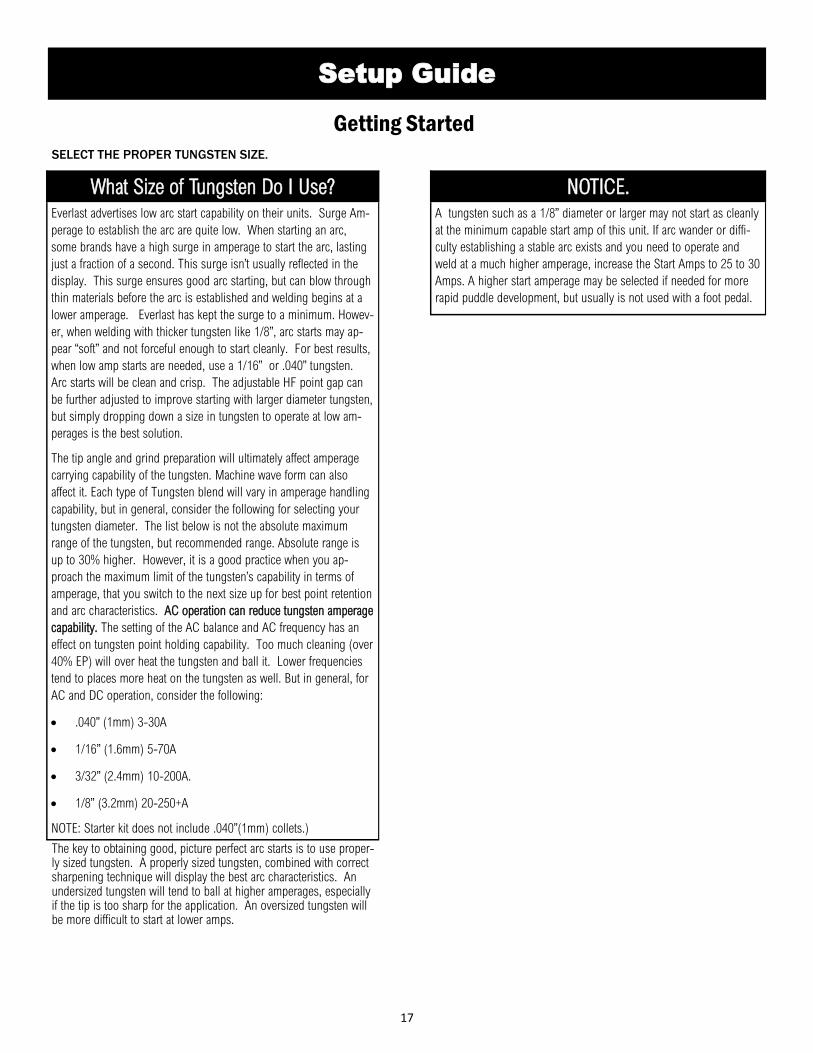
What Size of Tungsten Do I Use? Everlast advertises low arc start capability on their units. Surge Am-
perage to establish the arc are quite low. When starting an arc,
some brands have a high surge in amperage to start the arc, lasting
just a fraction of a second. This surge isn’t usually reflected in the
display. This surge ensures good arc starting, but can blow through
thin materials before the arc is established and welding begins at a
lower amperage. Everlast has kept the surge to a minimum. Howev-
er, when welding with thicker tungsten like 1/8”, arc starts may ap-
pear “soft” and not forceful enough to start cleanly. For best results,
when low amp starts are needed, use a 1/16” or .040” tungsten.
Arc starts will be clean and crisp. The adjustable HF point gap can
be further adjusted to improve starting with larger diameter tungsten,
but simply dropping down a size in tungsten to operate at low am-
perages is the best solution.
The tip angle and grind preparation will ultimately affect amperage
carrying capability of the tungsten. Machine wave form can also
affect it. Each type of Tungsten blend will vary in amperage handling
capability, but in general, consider the following for selecting your
tungsten diameter. The list below is not the absolute maximum
range of the tungsten, but recommended range. Absolute range is
up to 30% higher. However, it is a good practice when you ap-
proach the maximum limit of the tungsten’s capability in terms of
amperage, that you switch to the next size up for best point retention
and arc characteristics. AC operation can reduce tungsten amperage
capability. The setting of the AC balance and AC frequency has an
effect on tungsten point holding capability. Too much cleaning (over
40% EP) will over heat the tungsten and ball it. Lower frequencies
tend to places more heat on the tungsten as well. But in general, for
AC and DC operation, consider the following:
• .040” (1mm) 3-30A
• 1/16” (1.6mm) 5-70A
• 3/32” (2.4mm) 10-200A.
• 1/8” (3.2mm) 20-250+A
NOTE: Starter kit does not include .040”(1mm) collets.)
NOTICE. A tungsten such as a 1/8” diameter or larger may not start as cleanly
at the minimum capable start amp of this unit. If arc wander or diffi-
culty establishing a stable arc exists and you need to operate and
weld at a much higher amperage, increase the Start Amps to 25 to 30
Amps. A higher start amperage may be selected if needed for more
rapid puddle development, but usually is not used with a foot pedal.
18
Where Do I Connect The Torch?
Setup Guide
Getting Started
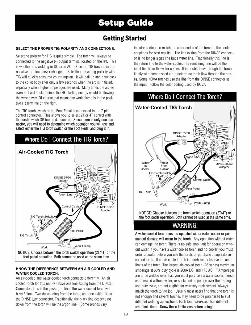
SELECT THE PROPER TIG POLARITY AND CONNECTIONS.
Selecting polarity for TIG is quite simple. The torch will always be
connected to the negative (-) output terminal located on the left. This
is whether it is welding in DC or in AC. Once the TIG torch is in the
negative terminal, never change it. Selecting the wrong polarity with
TIG will quickly consume your tungsten. It will ball up and draw back
to the collet body after only a few seconds when the arc is initiated,
especially when higher amperages are used. Many times the arc will
even be hard to start, since the HF starting energy would be flowing
the wrong way. Of course that means the work clamp is in the posi-
tive (+) terminal on the right.
The TIG torch switch or the Foot Pedal is connected to the 7 pin control connector. This allows you to select 2T or 4T control with the torch switch OR foot pedal control. Since there is only one con-nector, you will need to determine which operation you will use and select either the TIG torch switch or the Foot Pedal and plug it in.
KNOW THE DIFFERENCE BETWEEN AN AIR COOLED AND
WATER COOLED TORCH.
An air-cooled and water-cooled torch connects differently. An air
cooled torch for this unit will have one line exiting from the DINSE
Connector. This is the gas/argon line. The water cooled torch will
have 3 lines. Two descending from the torch, and one exiting from
the DINSE type connector. Traditionally, the black line descending
down from the torch will be the argon line. (Some brands vary
WARNING! A water-cooled torch must be operated with a water-cooler or per-
manent damage will occur to the torch. Any operation without water
can damage the torch. There is no safe amp limit for operation with-
out water. If you have a water cooled torch and no cooler, you must
order a cooler before you use the torch, or purchase a separate air-
cooled torch. If an air cooled torch is purchased, observe the amp
limits of the torch. The largest air-cooled torch (26 series) maximum
amperage at 60% duty cycle is 200A DC, and 175 AC. If Amperages
are to be welded over that, you must purchase a water cooler. Torch-
es operated without water, or sustained amperage over their rating
and duty cycle, are not eligible for warranty replacement. Always
match the torch to the job. Usually most users find that one torch is
not enough and several torches may need to be purchased to suit
different welding applications. Each torch size/class has different
amp limitations. Know these limitations before using!
Water-Cooled TIG Torch
Work Clamp
TIG Torch
Argon Line
Control Cable
Water From
Cooler
Water To
Cooler
in color coding, so match the color codes of the torch to the cooler
couplings for best results). The line exiting from the DINSE connect-
or is no longer a gas line but a water line. Traditionally this line is
the return line to the water cooler. The remaining line will be the
input line from the water cooler. If in doubt, blow through the torch
lightly with compressed air to determine torch flow through the hos-
es. Some NOVA torches use the line from the DINSE connector as
the input. Follow the color coding used by NOVA.
NOTICE: Choose between the torch switch operation (2T/4T) or the foot pedal operation. Both cannot be used at the same time.
TIG Torch Switch 2T/4T
Foot Pedal
DINSE 35/50 Adapter
Where Do I Connect The TIG Torch? Air-Cooled TIG Torch
Argon Line
Control Cable
TIG Torch
Work Clamp
NOTICE: Choose between the torch switch operation (2T/4T) or the foot pedal operation. Both cannot be used at the same time.
TIG Torch Switch 2T/4T
Foot Pedal
DINSE 35/50 Adapter
DINSE 35/50 Adapter
DINSE 35/50 Adapter
Work
Work
19
Setup Guide
Getting Started
GET A COOLER IF YOU HAVE A WATER-COOLED TORCH
OR WELD OVER THE AMP LIMIT OF YOUR AIR-COOLED
TORCH.
The new design of the PowerTIG units features an improved, seam-
less pairing of the welder and the water-cooler. The new PowerCool
series of water coolers are designed to stack under the units, with a
matched sheet metal and front and rear fairings. These will interlock
and provide a slip free connection.
For cooler connection, stacking of the welder over the cooler and
general information on using a water cooler with your unit, see the
water cooler manual. This unit is designed to stack with the new
PowerCool cooler. If you have any questions about purchasing the
correct cooler and assembly for your welder, contact Everlast.
SELECT THE PROPER STICK POLARITY.
The electrode holder, or stick torch (sometimes called a stinger) will
almost always be connected to the right terminal of the machine
( positive+). The work clamp will be connected to the negative. This
is known as DCEP (DC, Electrode Positive), Although it is an older
term, this is sometimes this is known as “reverse polarity” Most all
welding rods weld primarily in DCEP. DCEN (DC, Electrode Nega-
tive), although an older term is sometimes called “Straight Polarity”.
There are a few rods like E6011 which can operate either way, but
the preferred polarity is DCEP. Reasons for welding with DCEN are
usually to provide a softer arc, or reduce burn through.
IMPORTANT! This unit is designed to operate with most welding rods. However,
this unit is not designed for use with E6010. This unit should oper-
ate with E6011, however, which is considered to be a similar rod in
characteristics. When welding with E6011, some brands may weld
differently than others. Always select a good quality brand for best
arc stability. If instability is observed with E6011, switch brands.
This unit operates best with a short arc, so either drag the rod, or
hold a very short arc length so that arc outages with E6011 are not
experienced. A dragging motion, or a slight weave is recommend-
ed, but increasing the arc length may result in arc outages. Rods like
E7018, and E7014 are highly recommended for use.
Where Do I Connect The Stick Torch? Stick Torch
Work Clamp
Stick Torch
20
Setup Guide
Getting Started
If you are needing basic help getting started, here are some general settings and selections to get you started. This guide is intended to be only a start-
ing point, not a completely exhaustive source. Keep in mind that no guide is a substitute for practice and experience. You may find that your final set-
tings may be different from the ones listed. The following guide does not represent the maximum capability, or even the recommended capability of
the unit. However, it demonstrates what is considered to be a practical capability limit of multiple variables when factored together. It is possible to
weld thicker materials with the same amp range. However, as a best practice, the industry does not recommend heavy passes, rather thinner “stacked”
passes on thicker plate. Multi-pass welds are typically stronger, have less defects and require less amperage. On heavy gauge plate, such as 3/8” up
to 3 to 5 passes may be required. Additionally beveling of the joint is required for complete joint penetration, even at higher amperages. The thickness
rating takes into account the “heat sink” capability of the metal, and the power of the amperage to overcome the conductivity of heat of the metal used
using multiple passes. The position of the weld also influences the amperage, cup size, gas flow rate and tungsten size used. For the following recom-
mendations, these are all in “flat” position. Modify your settings accordingly. Vertical will require less amperage the more you weld “up hill”.
Amp Range Electrode Dia. Cup Number Flow Rate (CFH)
Standard Lens
Flow Rate (CFH)
Gas Lens
Metal Thickness
Aluminum (AC)
Metal Thickness
Steel/Stainless (DC)
3-30A .040 (1.0 mm) 4 or 5 5 to 7 4 to 5 .005” to .030” .003” to .035”
5-70A 1/16 (1.6mm) 4, 5, 6 6 to 12 6 .005” to .0612” .005” to .093”
10-200A 3/32” (2.4mm) 5,6, 7 or 8 10 to 18 8 to 12 .010” to .250” .08” to .375”
20-250A 1/8” (3.2mm) 6,7,8 or 10 15 to 25 10 to 18 .020” to .375” .015” to .500”
50A-350A 5/32 (4mm) 8-10 20-30 15-25 .050 to .625” .050” to .750”
Cup Size Inside Diameter
4 1/4”
5 5/16”
6 3/8”
7 7/16”
8 1/2”
10 5/8”
11 11/16”
12 3/4”
21
Component Identification and Explanation
1
2
3 4
5
6
Number Component Identification Component Note
1 Protective Cover Keep down and in place during welding activities and in storage.
Connect the TIG torch to this terminal for all TIG welding applications including AC. Connect the work clamp to this terminal for most Stick welding applications
3 Shielding Gas Connector (Quick Connect, 9mm tube Type 21 )
Single Shut-off Type for Inert Gas. Ref. EV-9MM-B-QUICKCONNECT-STDSET or 21KATS09MPX
Connect the work clamp to this terminal for all TIG welding applications including AC. Connect the Stick Electrode Holder (Stinger) to this termi-
nal for most Stick welding applications.
5 7 Pin Control Connector (5/8” Type GX16-7) Ref. EV-PANA7-625-PLUG
6 Handles Assy. Required, removeable for Low Clearance applications
Front Panel View
22
Component Identification and Explanation
1
Rear Panel View
2
3
5
6
Number Component Identification Component Note
1 Water Cooler Plug(240V 1ph, 4A max) This plug is to be used with Everlast water coolers only. Do not use with any other application.
2 Input Cable (Plug Not Included)
Plug is not included due to dual phase capability and the different wiring arrangements required. North America only: The unit may be operated on either 208-240V 1 phase or 208-240V 3 phase operation. North American standards require only 3 wires for 1 phase operation of welders. A neutral is not used or required. For 1 phase connection: Use Black for L1, White for L2, and Green for ground (not neutral) use. A NEMA 6-50P is the proper plug used for wiring single phase 240V welders in North America. For 3 phase connection: Use Black for L1, White for L2. Use the Red for L3 (for 3 phase operation only). Use the green wire for ground. If not operating the welder on 3 phase, clip the red wire and tape the end so that it is out of the way. If using it alternately on both 1 and 3 phase, bend the wire back and use electrical tape to fully tape to the cable sheath. The plug used for 3 phase may vary due to different industrial wiring configurations.
3 HF Ground Service Bolt* For use in a combined effort to mitigate any electrical interference that may be caused by the HF start of this unit.
4 Shielding Gas Inflow Connector (5/8” CGA) North America: 5/8” CGA connector. Other Markets: Hose Barb connection.
5 Fan location Periodically check for proper fan function and cleanliness.
6 Breaker/Power Switch. This switch doubles as the main power switch and disconnect switch. If this switch trips and the welder power turns off, a significant internal event or failure of the switch may have occurred. If this occurs, immediately remove from service and mark/tag according to regulations and contact Everlast Tech Support for further diagnosis and/or repair options.
NOTICE: Always consult national codes
and a local licensed electrician before
wiring this welder to any service.
4
*NOTICE:
If any electrical disturbance is noticed as a result of the High Frequency operation of this unit during arc starting, the HF service bolt should be connected directly to a 12 gauge wire that is
bonded directly to a copper ground rod driven into moist soil outside the building. Additionally, every 10 feet all metal items including any metal frame or sheeting of the building should be
connected together and grounded to separate copper ground rods driven into the ground around the perimeter of the building. This includes items such as tables, carts, rack material, metal
surrounds, etc. that may act as “antenna” to radiate/absorb HF energy. Additionally, all cords and welding leads should be twisted together and run directly to the work without coils or
excess cabling.
23
Component Identification and Explanation
Control Panel Layout
Number Component Identification Function/Component Note Value
1 On/Temperature/ Over Current/Voltage
“On” will be lit while unit is switched on to confirm power. If the temperature light is lit, an overheat has
occurred. See cool down and duty cycle instructions on page 11. An overcurrent light signals a signifi-
cant operational problem, including, operating on too low/high of voltage, too long of extension cord,
operating on a generator not rated as “clean power”, and/or some internal event that caused an excessive
current draw. Check for issues then attempt one reset, if this does not clear or reoccurs shortly after,
contact Everlast Tech Support.
NA
2 Start/End Amps Used with 2T/4T function and foot pedal. Used to establish and control intensity of start, and tail off amperage. Use minimum Amperage as default unless a larger diameter tungsten is being used.
5A/5A
3 Up Slope/Down Slope The Up Slope and Down Slope time control adjusts the ramp up and ramp down cycle time during 2T/4T use with the torch switch. Do not use with the foot pedal. (Set to “0”)
0-10/0-25 Seconds
4 Pre Flow/Post Flow Used to provide pre-weld gas flow and post-weld gas flow to protect the tungsten and the metal being welded from oxidation and porosity. Used with 2T/4T and Pedal.
0-10/0-25 Seconds
5 Pulse Includes Pulse Frequency,
Pulse Time On, Pulse Amps
Includes Pulse Frequency (represented as Hertz, or pulses per second) Pulse Amperage Percent (the drop of the pulse amps during the pulse cycle) and Pulse Time On Percent (how long the peak part of the pulse stays on in relation the lower amp stage of the pulse cycle).
0-500Hz 10-90% P.T.O.
5-95% Pulse Amps
6 AC Frequency Represented in Hertz, this is the number of times per second one complete cycle from Electrode negative to electrode positive and back to electrode negative occurs. Controls arc cone focus.
20-250Hz
7 AC Balance Represented as a percent of Electrode Positive (EP), this controls the cleaning/penetration of the arc when welding in AC mode. Usually set between 20% and 40%. Higher settings result in tungsten balling.
10-90% of positive
8 Function/Process Selectors Used to select turn on or select the desired features of the unit. When the LED is lit, this means that the process/function over the LED has been chosen.
NA
9 Stick Arc Force Control Allows you to set the arc reaction characteristics, from hard, driving, to soft, smooth arc by changing the amp increase when arc voltage falls in short arc conditions.
0-100%
10 Spot Weld Timer Used for creating regularly timed “spot welds”. Used to improve tacking/spotting consistency. 0-10 Seconds
11 Control Knob/Display Control knobs adjusts maximum amperage. The display displays only the welding amperage. The maxi-mum output reading will display only up to 200A in Stick mode.
TIG 5-250A Stick
5-200A
1
3
2
4
8
9
10
11
5 7 6
24
Component Identification and Explanation
Explanation of Functions and Welding Terms
AC. Alternating Current. Used in TIG mode on this welder to weld
Aluminum and Magnesium. AC does not function in Stick mode.
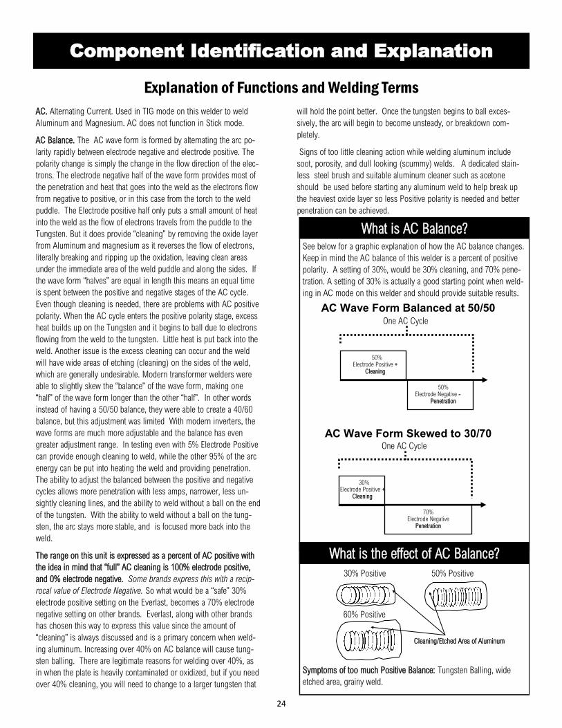
AC Balance. The AC wave form is formed by alternating the arc po-
larity rapidly between electrode negative and electrode positive. The
polarity change is simply the change in the flow direction of the elec-
trons. The electrode negative half of the wave form provides most of
the penetration and heat that goes into the weld as the electrons flow
from negative to positive, or in this case from the torch to the weld
puddle. The Electrode positive half only puts a small amount of heat
into the weld as the flow of electrons travels from the puddle to the
Tungsten. But it does provide “cleaning” by removing the oxide layer
from Aluminum and magnesium as it reverses the flow of electrons,
literally breaking and ripping up the oxidation, leaving clean areas
under the immediate area of the weld puddle and along the sides. If
the wave form “halves” are equal in length this means an equal time
is spent between the positive and negative stages of the AC cycle.
Even though cleaning is needed, there are problems with AC positive
polarity. When the AC cycle enters the positive polarity stage, excess
heat builds up on the Tungsten and it begins to ball due to electrons
flowing from the weld to the tungsten. Little heat is put back into the
weld. Another issue is the excess cleaning can occur and the weld
will have wide areas of etching (cleaning) on the sides of the weld,
which are generally undesirable. Modern transformer welders were
able to slightly skew the “balance” of the wave form, making one
“half” of the wave form longer than the other “half”. In other words
instead of having a 50/50 balance, they were able to create a 40/60
balance, but this adjustment was limited With modern inverters, the
wave forms are much more adjustable and the balance has even
greater adjustment range. In testing even with 5% Electrode Positive
can provide enough cleaning to weld, while the other 95% of the arc
energy can be put into heating the weld and providing penetration.
The ability to adjust the balanced between the positive and negative
cycles allows more penetration with less amps, narrower, less un-
sightly cleaning lines, and the ability to weld without a ball on the end
of the tungsten. With the ability to weld without a ball on the tung-
sten, the arc stays more stable, and is focused more back into the
weld.
The range on this unit is expressed as a percent of AC positive with
the idea in mind that “full” AC cleaning is 100% electrode positive,
and 0% electrode negative. Some brands express this with a recip-
rocal value of Electrode Negative. So what would be a “safe” 30%
electrode positive setting on the Everlast, becomes a 70% electrode
negative setting on other brands. Everlast, along with other brands
has chosen this way to express this value since the amount of
“cleaning” is always discussed and is a primary concern when weld-
ing aluminum. Increasing over 40% on AC balance will cause tung-
sten balling. There are legitimate reasons for welding over 40%, as
in when the plate is heavily contaminated or oxidized, but if you need
over 40% cleaning, you will need to change to a larger tungsten that
will hold the point better. Once the tungsten begins to ball exces-
sively, the arc will begin to become unsteady, or breakdown com-
pletely.
Signs of too little cleaning action while welding aluminum include
soot, porosity, and dull looking (scummy) welds. A dedicated stain-
less steel brush and suitable aluminum cleaner such as acetone
should be used before starting any aluminum weld to help break up
the heaviest oxide layer so less Positive polarity is needed and better
penetration can be achieved.
What is AC Balance? See below for a graphic explanation of how the AC balance changes.
Keep in mind the AC balance of this welder is a percent of positive
polarity. A setting of 30%, would be 30% cleaning, and 70% pene-
tration. A setting of 30% is actually a good starting point when weld-
ing in AC mode on this welder and should provide suitable results.
50% Electrode Positive +
Cleaning
50% Electrode Negative -
Penetration
One AC Cycle
AC Wave Form Balanced at 50/50
30% Electrode Positive +
Cleaning
70% Electrode Negative
Penetration
One AC Cycle
AC Wave Form Skewed to 30/70
What is the effect of AC Balance?
Symptoms of too much Positive Balance: Tungsten Balling, wide
etched area, grainy weld.
30% Positive 50% Positive
Cleaning/Etched Area of Aluminum
60% Positive
25
Component Identification and Explanation
Explanation of Functions and Welding Terms welding amps. Once the current has declined though, the next “click”
of the torch switch will terminate the arc.
End Amps. This is the current value set for the end of the weld cy-
cle. When 2T or 4T with the torch switch, this is the final current set
used to taper off and fill the crater at the end of the weld. For foot
pedal use, this value should be kept at minimum for proper tail off.
High Frequency Start. Depicted as HF start on the panel, this is a
touchless type of start. When HF start is selected, the user positions
the torch 1/8” or less above the weld area and either presses the foot
pedal or the torch switch and the arc will jump. This start is created
by a HF system similar to the ignition system on older automobiles.
A high voltage, low amperage current is created which jumps from
AC Frequency. AC frequency is the number of times per second that
the AC completely cycles between positive and negative polarity. The
number of cycles per second is referred to as Hertz (Hz) or frequen-
cy. Standard transformer welders typically have a fixed frequency of
60 Hz (North American market, other markets may be only 50 Hz).
This is because of the standard input frequency from the power com-
pany is only 60hz(50Hz other regions). Transformer welders only
have the ability to transform voltage, not the frequency. Whatever
frequency is fed into the transformer, will be the frequency that is
output at the torch. However, inverters welders have the ability to
change AC frequency on the output side, despite the input frequency.
This unit has the ability to control AC frequency from 20 to 250Hz.
When operating at lower AC output frequency, the arc is wide and
lazy, but puts more heat into the weld. Operating at higher frequency
focuses the arc, and pinpoints the heat into a narrower area. Higher
frequencies allow the arc to be better directed, but may slow forward
travel speed.
Arc Force. The arc force function only works in Stick mode. Arc
force is used to offset the loss of overall wattage (VxA=W) as arc
length is shortened and voltage begins to drop while stick welding. It
offsets the drop in voltage by injecting extra amps into the weld when
voltage drops below 20V. This enables the amperage to react aggres-
sively or mildly, depending upon settings, to prevent arc outages,
and allowing the user to hold a tight arc and maintain better control.
DC. Direct Current. Used to weld Steel, Stainless Steel (Inox),
Chrome Moly, Titanium, and more. Not used with Aluminum and
Magnesium.
Down Slope. This is a function to be used with 2T/4T remote opera-
tion, not with the foot pedal. This timer controls the decrease of the
amperage and provides a window to fill the crater as the puddle be-
gins to cool before the arc terminates. This is not to be used with
the foot pedal, or a delay, or sudden increase in amps at arc termina-
tion would result. If set with a long Down-Slope, and 4T is used, the
switch can be toggled to abort the downslope cycle and return to
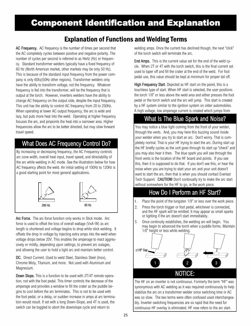
What Does AC Frequency Control Do? By increasing or decreasing frequency, the AC Frequency controls
arc cone width, overall heat input, travel speed, and directability of
the arc while welding in AC mode. See the illustration below for how
AC frequency affects the weld. An initial setting of 100Hz to 120Hz is
a good starting point for most general applications.
200 Hz 60 Hz
What Is The Blue Spark and Noise? You may notice a blue light coming from the front of your welder,
through the vents. And, you may here this buzzing sound inside
your welder when you try to start an arc. Don’t worry. That is com-
pletely normal. That is your HF trying to start the arc. During start up
the HF briefly cycles as the unit goes through its start up “check” and
you may also hear it then. The blue spark you will see through the
front vents is the location of the HF board and points. If you see
this, then it is supposed to do that. If you don’t see this, or hear the
noise when you are trying to start your arc and your unit doesn’t
want to start the arc, then that is when you should contact Everlast
Tech Support. CAUTION! Don’t continually try to make the arc start
without somewhere for the HF to go, ie the work piece.
How Do I Perform an HF Start?
Place the point of the tungsten 1/8” or less over the work piece.
Press the torch trigger or foot pedal, whichever is connected, and the HF spark will be emitted. It may appear as small sparks or lighting if the arc doesn’t start immediately.
Once continuity establishes, the welding arc will begin. You may begin to advanced the torch when a puddle forms. Maintain 1/8” height or less while welding.
2
≤1/8” Gap
1 3
NOTICE: The HF on an inverter is not continuous. Formerly the term “HF” was
synonymous with AC welding as it was required continuously to help
stabilize the arc on a transformer welder since switching time in AC
was so slow. The two terms were often confused used interchangea-
bly. Inverter switching frequencies are so rapid that the need for
continuous HF overlay is eliminated. HF now refers to the arc start.
26
Component Identification and Explanation
Explanation of Functions and Welding Terms
the Tungsten to the work piece when activated. Once the machine
sends the HF impulse to the torch, the HF energy jumps, the welding
arc will initiate after the HF establishes a current path and the HF
shuts off. On this unit if the HF stays on, but does not start an arc or
an arc is not sensed, the unit will stop output of the HF after approxi-
mately 2 to 3 seconds. If this happens an error code “205” will be
displayed temporarily, meaning the switch is either stuck closed, or
the arc has been activated too long without an arc start. This is a
safety feature as HF energy can affect surrounding electronic items.
Hot Start. This setting controls the intensity of the arc start by con-
trolling the initial amps at the start of the weld cycle. It is used to
improve arc starting and reduce the time needed to establish a pud-
dle and helps to prevent porosity at the beginning of the weld. This
can refer to either TIG or Stick. The Hot start is controlled through
the “Start Amps” of the welder. In TIG mode, this follows the pre-
flow control cycle.
Lift Start. Lift start requires touchdown and lifting up of the Tungsten
to start the Arc. It is usually used only with DC output since some
contamination of the tungsten is possible. But it can also be used
with AC where HF energy is prohibited, such as in a hospital envi-
ronment. There are two types of Lift Start. The first is a live lift start.
This means the tungsten is always electrically live until the arc is
started. When the tungsten is touched to the metal, continuity is
sensed and the welder sends welding power as soon as the continui-
ty is broken. This unit does not have this type of Lift Start. Some of
our units have this type start, but it is not featured on this machine.
If you need this type of start on a welder, contact Everlast for other
product information. The other type of lift start is a “remote lift start”.
This is the type this unit has unit has. It functions essentially the
same except, the tungsten is not electrically live and the torch switch
or foot pedal must be used to make the torch live. This is a safer
form of lift start and helps prevent accidental starting of the arc. It
also means that the start type can be used with the welder program-
ming in 2T and 4T mode, or with the foot pedal.
Post Flow. Post Flow is the amount of time (in seconds) that the
shielding gas flows after the arc is terminated. This is an important
function. The flow of shielding gas after welding is stopped helps to
1) Cool the torch and tungsten and prevents oxidation of the tung-
sten as it cools. 2) Provide cooling and shielding while the weld
puddle solidifies and cools. This helps to prevent the weld from
forming porosity and prevents oxidation of the weld as it cools. Post
Flow should be increased at the Amperage increases. For simple
calculation, add one second of Post Flow for every 15 to 25 Amps
used. At a minimum, 2 to 3 seconds should always be used. To
properly use Post Flow, the torch should be held in place over the
weld after termination until the gas shuts off.
Pre Flow. Pre Flow is the amount of time (in seconds) that the
shielding gas flows before the weld starts. It is very important that
the Pre Flow be set for at least a short flow before any weld. The Pre
-Flow not only purges the torch of any contamination, but it also
establishes a protective envelope of shielding gas around the weld
before the arc initializes. This protects the tungsten, and helps to
establish an arc more quickly by surrounding the tungsten and work
with more easily ionized gas so that arc starts are more efficient. It
also allows time for the gas flow to stabilize before the arc is struck.
When initializing the Pre Flow a “rush” of gas can often be heard just
ahead of the arc strike. Then the gas flow will quieten down as the
weld begins. This is normal. This rush of gas is caused by several
things, but it is in part due to regulator attempting to regulate the
sudden rush of gas. As it does this, extra gas may be consumed
until the regulator has had time to react. The extra flow of gas may
create turbulence around the weld. The Gas flow rate may also tem-
porarily increase due to the back pressure “ballooning” of the gas
lines. As the slightly swollen gas lines stabilize, extra gas is pro-
pelled as the solenoid opens relieving the back pressure. .3 to .7
seconds is usually enough to allow the “gas rush” to stabilize.
How Do I Perform a Lift Start?
Rest the edge of the cup on the work piece so that the tungsten is slightly off the work. Press the trigger or foot pedal. Quickly rotate the tungsten to the work using the cup edge as a pivot.
A small spark may be noticed as it touches. Once the Tungsten touches, quickly and seamlessly rotate the cup back to draw an arc.
Raise the cup to establish the arc to 1/8” or less in height.
Allow the puddle to form and move the torch forward maintain-ing 1/8 or less height.
≤1/8” Weld Height
3
2 1
4
NOTICE: The arc start will be delayed by the amount of time chosen for Pre Flow. If Pre Flow is set for 2 seconds, the arc will not start for 2 seconds. This is sometimes easy to forget, especially when tacking or “Bump” welding.
27
ing on thin materials. It can also help maintain a proper bead profile
on a thin edge weld or prevent burn through on extremely thin metal.
A fast pulse speed will make fine ripples in the weld while a slow
pulse speed will give a much more coarse, but visually appealing
result. There are limitless ways to adjust the pulse. Regardless of
how you choose to adjust the pulse, always keep in mind, that the
basic purpose of the pulse is to average the heat input while main-
taining penetration and welding speed.
AC Pulse TIG operation is setup the same. Do not confuse AC cy-
cling between EP and EN as pulse. It is not. You are still adjusting
the amperage of the AC pulse, and skewing the balance and chang-
Is There a Better Way to Understand Pulse? Pulse is essentially a wave form created by the pulsing amperage. This wave form can be skewed, expanded, compressed, increased or decreased in magnitude. Each change in Amps, Pulse Time On Bal-ance, and Frequency all affect average heat being put into the weld. The examples below attempt to explain the parts of the pulse and how each part of the pulse functions.
Component Identification and Explanation
Explanation of Functions and Welding Terms
Pulse. The TIG pulse creates two amp values, a high and a low value
that cycle back and forth between each other while welding. The
upper amperage is called the “Welding Amps” (sometimes referred to
as “Peak” current.) The lower amperage is called “Pulse
Amps” (sometimes called “background” or “base” current). Pulse
has several uses and can be used to control arc directability, arc
cone width, heat spread, penetration and even weld appearance. It is
particularly useful on metals that are prone to structural deterioration
or burn through. Pulse creates a lower Amp average, and “felt heat”
by varying one or more of several adjustable parameters of the pulse
This welder features several adjustable parameters that affect the
pulse operation:
1. Pulse Amps (Base). Base Amps is the low Amperage value of
the pulse. When you adjust the base Amps in pulse mode, you
are actually setting a ratio of base Amps to peak welding Amps.
Base amps are expressed as a percentage of Peak welding
Amps. So, when you set base amps, you are only setting it as a
percentage, not the actual Amps. As you increase Peak weld-
ing Amperage through the use of the foot pedal, or the panel
control, the pulse will maintain the same ratio of Base to Peak
welding Amps, raising the base Amps automatically. To illus-
trate: Adjust the Peak (main welding) Amps, to 100. Set the
base Amps to 50%. This will yield a 50 Amp value for the base
Amps. The foot pedal controls both Peak welding Amperage
and Base Pulse Amperage simultaneously, using the pre-set
ratio.
2. Pulse Frequency. Pulse speed or frequency as it is referred to
is measured in the standard unit “Hertz.” Simply, it is the num-
ber of pulses per second that occur. Pulse frequency controls
the arc constriction and also helps with heat management. A
slower pulse frequency around 1 to 3 hertz gives the “stacked
dime” appearance. At higher frequencies the “stacked” appear-
ance will be lost while heat control is maximized.
3. Pulse Time On (Balance). Pulse Balance is the percentage (%)
of time that the pulse stays in the TIG (Peak) pulse Amp stage of
the cycle. Increasing the Pulse time-on will increase the dura-
tion the Peak Amp stage of the cycle which in turn will increase
the heat and will increase penetration. Pulse Balance is also
known in the industry as “duty cycle”. For welding purposes the
term “Pulse Time On” is used here.
Setting up the pulse is not a process where a fixed adjustment pro-
cedure can be assigned or rigidly recommended. Changes to fre-
quency, balance, and time will skew the final result. A slow pulse
with a equal 50% pulse time on and somewhere around a 50-75%
Pulse Base Amp setting is typically used to help with timing the
addition of filler metal to the weld puddle. A higher pulse frequency
level that is combined with variations in Pulse Time On and a narrow/
wider ratio can be used to prevent burn through and speed up weld-
1 S
SECONDS
EXAMPLE 2 Peak Pulse Amps: 100 amps Base Amps: 50% Pulse Time On : 50% DC Pulse Frequency: 25Hz
AMPS
100
50
EXAMPLE 1 Peak Pulse Amps: 100 amps, Base Amps: 50% Pulse Time On: 50% DC Pulse Frequency: 1 Hz
AMPS
SECONDS 1 S
25
100
EXAMPLE 3 Peak Pulse Amps: 100 amps Base Amps: 25% Pulse Time On: 75% DC Pulse Frequency: 3 Hz
2 S
AMPS
SECONDS
1 S 3 S 50
100
Pulse Amps
Welding Amps Pulse Time ON
Pulse Hz
28
ing difficulty is encountered with larger diameter tungsten.
2T mode and 4T mode offer two modes used with the torch switch
that is included with the TIG torch. This is used to control the torch
cycle through preset functions of Pre/Post Flow, Up/Down Slope,
Start/End Amps. In 2T mode, the torch switch is simply pressed
and held to start the arc and cycle the preprogrammed settings.
Once arc termination is desired, the switch is released. In 4T mode,
the Torch trigger is held down to start the pre-flow and initiate the
arc at the “Start Amp” setting. The switch is then released and the
unit begins up-slope until it reaches the welding current. The weld is
continued without the switch being pressed. Once the weld is near-
ing finish, the torch switch is once again pressed and held to down
slope to the “End Amp” setting. Then the torch is released to termi-
nate the arc and begin post flow.
Shielding Gas. Shielding Gas is necessary while TIG welding. The
shielding gas used for the TIG process is 100% Argon. Shielding
gas protects the weld from oxidation by the atmosphere while the
weld puddle is still molten. Gas flow rates are controlled by the sup-
plied regulator. Too little gas flow will cause porosity, heavy scale
and or oxidation. Too much gas flow is wasteful and can also create
a turbulent flow, which can pull the atmosphere into the weld, creat-
ing oxidation.
Start Amps. This is the initial Amperage of the weld in TIG mode.
This is the starting point, at which the arc initiates. The Start Amps
are sometimes referred to as “Hot Start”. It becomes particularly
effective when using the torch switch for welding aluminum by allow-
ing a more rapid wet in at the beginning of the weld. For larger diam-
eter tungsten, the Start Amps can be increased to provide a more
stable low end start with the foot pedal.
Spot Weld Timer. The Spot weld timer simply is an Arc-On timer for
TIG welding. The use is intended to help the user to create better
tack welds with improved consistency in size and penetration. Once
Component Identification and Explanation
Explanation of Functions and Welding Terms
ing the frequency similarly to the DC pulse.
With the pulse turned on, you may notice the amp display reading at
odd amperages, or at a value not set before welding. This is normal
as the welder is attempting to average and sample the welding am-
perage in real time. Slower Pulse frequencies are more apt to dis-
play truer max and min Pulse Amp values. This randomizing/
averaging happens because it would be impossible for the display to
cycle between those values at the same pace of the pulse frequency.
For example: If pulse frequency is at 100Hz, the display cannot
change the readout 100 times a second to display both values. Even
if it could cycle that fast, the display would not be readable.
Regulator. Controls the flow rate of the shielding gas at the cylinder.
Remote. Remote refers to the ability to control the weld cycle at a
distance. For this welder, all forms of TIG welding, whether with Lift
Start or High Frequency Start, require a remote to operate. A remote
can be a foot pedal, torch switch, or torch mounted slider or Amptrol.
All three start and end the arc as well as control other parts of the
weld cycle to varying extents. The unit has three Remote settings to
choose from. The first two, 2T and 4T, deal exclusively with torch
switch operation. The third is pedal control.
Pedal mode is the most straight forward. Operation is quite simple.
The maximum amperage is set on the panel. Then the foot pedal is
used to start and stop the arc as well as vary the amperage from the
minimum welding setting, up to the maximum welding setting select-
ed on the panel. When used in pedal mode, only the Pre Flow, Post
Flow and Start Amps should be adjusted. All other values, which
include the Up Slope, Down Slope, and End Amps should remain
zeroed out, or set at the minimum allowed setting. For the most part,
even Start Amps can be left at the minimum setting, unless arc start-
How Does 2T and 4T Work? The torch switch has two possible modes of operation. The first is a “press and hold”. The second allows the switch to be released to weld, but offers separate motions to start and stop the arc. See below for how each function is activated by movements of the torch switch.
2T Torch Operation Effect on Weld Cycle.
4T Torch Operation Effect on Weld Cycle. PREFLOW POST FLOW
= UP ON SWITCH = DOWN ON SWITCH
WELD VALUE WELD VALUE
PREFLOW
WELD VALUE
POST FLOW START AMPS/WFS
START AMPS/WFS END AMPS/WFS
END AMPS/WFS
NOTICE: While using the foot pedal, and the optional slider switch, the weld-
er’s digital display will revert back to the minimum amp setting on the
welder after the arc is terminated and it will not display maximum set
amps. It will only display maximum set amps while the unit is being
adjusted for amperage. While welding the display will read actual
weld amperage. After 3-4 seconds the display will default back to the
minimum amp reading. When using 2T or 4T control modes, the
amps will register the maximum set amps until the arc is started. To
see the maximum set amperage in the pedal mode without the arc
on, simply make a small adjustment in the main adjustment knob
while the Welding Amps light is lit. The unit will revert to the
“setting” mode and display selected maximum amperage.
29
Component Identification and Explanation
Explanation of Functions and Welding Terms
the trigger is activated, the arc will stay turned on for the amount of
time selected. After the time has expired, the welding arc will shut
down. To restart the arc, the trigger will need to be released and
retriggered. This is not meant to be used with or serve as a control-
ler for Tong-Type Spot welders.
Stick. In North America, this is the SMAW process (Shielded Metal
Arc Welding) In other regions this is called MMA (Manual Metal Arc).
Stick is an older term to refer to the stick like appearance of the weld-
ing electrodes (also known as welding rods). This is a versatile pro-
cess and can be used in adverse conditions where TIG cannot. For
welding, this unit is not recommended for use with E6010. However,
E6011 may be used, but performance may be brand dependent. A
short arc length should be used. A dragging motion is recommend-
ed and a higher arc force setting is recommended when welding with
E6011. For best results with stick welding, Everlast recommends
E7014 and E7018 for general purpose use and fabrication. Stainless
rods and aluminum rods may also be used.
Up Slope. This function is used with 2T and 4T settings and is not
used with the foot pedal. (If it were used it would cause a delay in the
ramp up ability of the amps). The Up Slope time allows the arc to
uniformly transition from Start Amps to the Welding Amps, by in-
creasing the amperage as you would with a foot pedal.
Welding Amps. This is the main Amperage control. When used in
the context of Pulse, this is the “Peak” part of the pulse while the
Pulse Amps is the “Base Amp” part of the pulse. Without Pulse, the
main welding amps simply controls the Amperage of the welder.
How Do I Start an Arc With Stick? There are two basic types of arc starting methods used. The tapping motion allows pin point placement of the arc, while the scratch start method is similar to a match strike and is easier for beginners.
Tapping Scratch/Match Method
30
Typical Everlast and NOVA Torch Assembly (17,18, 26 Series)
(Some parts may not appear exactly the same but are equal in assembly order and type.)
Tungsten not included, but available in select Consumable Kits on the website at www.everlastwelders.com.
Consumables are standard sized for series 3 torches, and interchange with consumables made for similar torches with similar nomenclature.
# Description Size/Type Part# Alternate Ref. Note
1 Back Cap Long NVA57Y04-3 57Y02
1 Back Cap Medium NVA41V35-3 41V35 Or 300M
1 Back Cap Short NVA57Y04-3 57Y04
2 Collet .040” NVA10N22-3 10N22 1.0mm
2 Collet 1/16” NVA10N23-3 10N23 1.6mm
2 Collet 3/32” NVA10N24-3 10N24 2.4mm
2 Collet 1/8” NVA10N25-3 10N25 3.2mm
3 Torch Body/Handle 17,26, or 18 Call for App. Varies by Type
4 Heat Shield 17/26/18 NVA-HS172618 Heat Shield Interchanges with similar aftermarket
5 Collet Body Universal one size fits 1/16” to 1/8” Stock Stock Universal Collet Body and Collets supplied with original starter kit
5 Collet Body .040” NVA-10N30 10N30 1.0mm, match to collet size
5 Collet Body 1/16” NVA-10N31 10N31 1.6mm, match to collet size
5 Collet Body 3/32” NVA10N 10N32 2.4mm, match to collet size
5 Collet Body 1/8” NVA10N28 10N28 3.2mm, match to collet size
6 Cup 4 NVA-10N50-3 10N50 Standard, non gas lens 1/4”
6 Cup 5 NVA-10N49-3 10N49 Standard, non gas lens 5/16”
6 Cup 6 NVA-10N48-3 10N48 Standard, non gas lens 3/8”
6 Cup 7 NVA-10N47 10N47 Standard, non gas lens 7/16”
6 Cup 8 NVA-10N46-3 10N46 Standard, non gas lens 1/2”
Component Identification and Explanation
18 Series Water-Cooled Welding Torch (Typical Type) Parts and Assembly.
31
7 PIN CONNECTOR FOR 10K or 22K Ω FOOT PEDAL
To Pedal or Torch Switch ON/OFF
To Pedal or Torch Switch ON/OFF
1
2
3 4
5
6
7
Low Middle High
Foot Pedal (10k-22k Ω)
Note: This unit is designed to accept several different Ohm values, including the older 47K (50K) Ohm pedal without significantly
affecting operation. The pinout of the pedal is unchanged in either case.
Bridge a Jumper to Pin 6
Bridge a Jumper to Pin 7
Potentiometer (VR)
Component Identification and Explanation
32
TROUBLE CODE WITH WARNING LIGHT/UNIT
STOPS WELDING BUT IS TURNED ON.
DIAGNOSIS
801 OVER OR UNDER VOLTAGE. Check power input cable for length/size, check input voltage. Run-
ning on poor quality power supply or dirty power from generator.
802 OVER TEMPERATURE/ DUTY CYCLE EXCEEDED. Allow unit to rest for 15 minutes. Check for
obstacles, clean welder, and heat sinks. Make sure unit is unplugged for 30 minutes before opening
up for cleaning.
804 OVER CURRENT. Check to make sure input power cable is correct length and size. Internal unit
fault or low input voltage. Possible issue running on generator with dirty power. Identify cause,
plug directly into the receptacle. Cycle the switch one time. If the code does not clear, call Everlast
Tech Support.
805 TORCH SWITCH IS STUCK CLOSED. This simply means that the arc has been trying to start and
the HF has been cycled on for too long. If this does not clear after releasing the foot pedal, turn off
welder immediately and check torch switch for stuck contact. Check foot pedal for complete return
or stuck micro-switch. Do not hold down the switch or pedal without attempting to strike an arc.
Doing so for more than 2 seconds without starting will cause this error code.
OTHER CONTACT EVERLAST
Troubleshooting
Error Codes
33
Troubleshooting
Common Welding Issues
NO. Trouble Possible Cause Solution
1. Unit is switched on, but the power light isn’t on. Switch damaged. Service Breaker/ Input Line Damaged
Check. Replace.
2. After welding machine is overheating and the fan
does not work.
Fan damaged. Fan connector plus is loose
Replace. Check. Reinstall.
3. When switch/pedal is pressed, no gas flows. Empty Cylinder/ Closed Valve. Regulator Faulty/shut off. Solenoid Dirty/Stuck Shut Damaged PCB
Check. Replace/Open Check, Open Check. Clean or Replace. (Contact Everlast Technical Support) Contact Everlast Technical Support
4. Intermittent, wandering arc. Work Clamp not connected directly to part being welded. Work Clamp worn/damaged Torch height too high.
Reconnect. Replace. Reduce TIG torch height to under 1/8”. Drag Welding Rod (Stick)
5.
Arc will not start unless lift started. Points misadjusted, worn or dirty. HF not selected
Check HF point gap. Clean and set to .035” Contact Technical Support for details. Make sure unit is set to HF
6. Tungsten is rapidly consumed. Inadequate gas flow. Too small of tungsten. Wrong shielding gas. Using green tungsten. Wrong polarity. Possible contamination of shield-ing gas from gas supplier.
Check gas flow. Check for Leaks thoughout system/regulator/tank. Check for 100% Argon. Use Lanthanated 2% or any other type besides Green (Pure) or Zirconiated. Put torch in Negative.
7. Tungsten is contaminated, arc changes to a green color.
Tungsten is dipping into weld. Too long of stick-out. Tungsten is melting.
Check and adjust stick out to 1/8 inch. Reduce stick-out to less than 1/4”. Reduce amperage or increase tungsten size.
8. Porosity of the Weld. Discolored weld color. Tungsten is discolored.
Low flow rate of shielding gas. High flow rate of shielding gas. Tungsten stick-out is too far. Too short of post flow period. Wrong TIG cup size. Possible gas leaks internally or externally due to loose fittings. Base metal is contaminated with dirt or grease.
Increase flow rate on regulator. Check for kinks in tubing. Increase post-flow time. Reduce stick-out to less than 1/4”. Increase cup size, or use gas lens. Clean metal thoroughly with approved metal cleaner, or use acetone and a rag to clean metal
9. Weld quality is poor. Weld is dirty/oxidized, or porous.
Drafty conditions. The welder is located on the workpiece and is blowing gas off due to fan activity. Solenoid is sticking. Too short of pre-flow or post-flow
Eliminate drafts. Move welder. Check if there is sufficient shielding gas left in tank. Check gas flow. Adjust for higher flow of gas. Listen for audible click of gas solenoid. If no click is heard, then contact Everlast Support. Clean weld properly. Increase pre flow or post flow.
10. Unstable Arc. Poorly ground or shaped tungsten. Bad work clamp connection. Metal is indirectly connected through table or other item.
Regrind to proper point. Wrong polarity. Place torch in DC negative (-). Connect work clamp directly to item being welded.
11. AC TIG will not weld properly. Wrong polarity. Work clamp is not connected direct to work. Balled Tungsten AC Balance too high AC Frequency too low Contaminated Gas
Check and change immediately. TIG torch is always negative. Put clamp direct to work. Sharpen Tungsten. Do not use Ball Set for approximately 30% Increase to 50 Hz or higher Source new cylinder or new supplier
12. Other. Contact Everlast
34
Note: Although point gap adjustment is usually considered a part of regular maintenance, and is not an item covered by warranty, the following adjustment process is intended for experienced users only. If you suspect you have a problem with the point gap due to hard starting of the arc, contact Everlast Tech Support before proceeding with point gap adjustment for proper diagnosis and more detailed adjustment procedure.
To open the unit to adjust the point gap:
1) Unplug the welder. Wait 20 minutes to allow capacitors to discharge to prevent possible shock and injury. WARNING: If possible, do not touch unrelated circuits and components, especially capacitors, during this adjustment process to reduce the chance of possible shock and injury.
2) Remove the rear plastic cover by removing screws with a small screw driver, remembering to remove screws holding the cover that are located on the bottom. There is no need to remove the front cover.
3) Remove screws in metal cover. Gently spread the bottom of the cover with your fingers about 1” on either side. Simultane-ously slide the metal cover toward the rear and pull up to remove the cover from the chassis.
4) Locate the HF board located toward the front of the unit. This board is mounted under the top metal pan and the points should be visible from the left side (side determined by facing the front of the unit). The points will have two carbon contacts hanging under the bottom of the metal pan. These will be held in place by two brass nuts that are used to lock the contacts in place. Check the point gap with either a feeler gauge by sliding it between the points. Access may be tight, but try several angles to get the feeler gauge in between the points. The gap should be set to anywhere between .030 “and .045”, with .035” being preferred.
5) If adjustment is needed, loosen the locking nuts slightly so that the end of the brass contact holder can be rotated with a small flat bladed screw driver. Slowly adjust the points until slight contact is made with the feeler gauge. When completed hold the contact in place with the screw driver while the locknut is retightened, making sure the contact holder does not rotate in the process.
6) Recheck the point gap. Make any necessary re-adjustments. Reassemble the unit.
HF Point Gap Location
Locking Nut
Adjustment Screw
Maintenance
Setting Point Gap
Regular Cleaning and Inspection.
Every three to four months, you should clean and inspect the internal parts of the unit. Excessive build up of material, like metal dust, on boards can cause malfunctions. This is important to keeping your welder running for many years into the future. It is important to note that cleaning doesn’t void your warranty, but rather ensures it! Keep your welder covered when not in use. You can purchase a cover for your welder direct from Everlast. CAUTION! When blowing out with dry compressed air, be sure to use safety glasses. To Clean out your unit: 1. Unplug the unit for 20 minutes before beginning.
2. Unscrew all screws in rear plastic panel and remove.
3. Unscew all screws in metal cover and remove cover carefully, avoiding pinching any wires close to the cover.
4. Blow out gently with dry compressed air.
5. Inspect all circuits and connections. If possible reseat connectors and blow out connections while doing it.
6. Reassemble.
7. Document and report any anomalies or areas of concern to Everlast Tech Support as soon as possible.