Page 1
242-A Evaporator HEPA Filter In-Place Leak Test (Aerosol Test)
Type
CONTINUOUS Document No.
3-VBP-656 Rev/Mod
D-3 Release Date
02/22/2018 Page
1 of 14
Tank Farm Maintenance Procedure 242-A Evaporator
USQ # N/A-4
CHANGE HISTORY ( LAST 5 REV-MODS )
Rev-Mod Release Date Justification Summary of Changes
D-3 02/22/2018 Maintenance Request
Add Section 4.2 Performance Documents and "GHS-SDS and/or
MSDS for ATI PAO-4 (GHS-SDS and/or MSDS #065495)" to
Performance Documents. Update Aerosol Generator / Operating
Pressure Ranges for Aerosol Generators table in Section 5.5
D-2 12/11/2017 Maintenance Request
Add Steps 2.2.3, "3-VBP-656 is performed first, if used in
conjunction with procedure 3-VBP-657".and 2.2.4,"Airflow
readings and results from 3-VPB-656 can be transcribed to 3-
VBP-657 to eliminate redundant air flow testing" to Section 2.2.
D-1 08/16/2017 Maintenance Request
Initial and Date removed from 5.2.1, Initial and Date removed
from 5.10.1, step numbers changed to coincide with data sheet
changes. Records section upgraded to current standard.
D-0 08/27/2015 Changes from Periodic Review Page 3 Added 2.1 Definitions. Page 12 Removed Note, and Steps
5.8.2, 5.8.3, 5.8.4.
C-3 11/19/2014 CHAMPS Removal Removed reference to CHAMPS, updated records statements and
removed next periodic review date.
Table of Contents Page
1.0 PURPOSE AND SCOPE ................................................................................................................ 3
1.1 Purpose ................................................................................................................................ 3
1.2 Scope ................................................................................................................................... 3
2.0 INFORMATION............................................................................................................................. 3
2.1 Terms and Definitions......................................................................................................... 3
2.2 General Information ............................................................................................................ 3
3.0 PRECAUTIONS AND LIMITATIONS......................................................................................... 4
3.1 Personnel Safety.................................................................................................................. 4
3.2 Equipment Safety ................................................................................................................ 4
3.3 Radiation and Contamination Control ................................................................................ 4
3.4 Environmental Compliance ................................................................................................ 4
4.0 PREREQUISITES .......................................................................................................................... 5
4.1 Special Tools, Equipment, and Supplies............................................................................. 5
4.2 Performance Documents ..................................................................................................... 5
5.0 PROCEDURE ................................................................................................................................. 6
Page 2
242-A Evaporator HEPA Filter In-Place Leak Test (Aerosol Test)
Type
CONTINUOUS Document No.
3-VBP-656 Rev/Mod
D-3 Release Date
02/22/2018 Page
2 of 14
5.1 Test Equipment Preparation ................................................................................................ 6
5.2 Pre-job Survey and Visual Inspection Checklist ................................................................ 6
5.3 Differential Pressure (DP) Readings ................................................................................... 7
5.4 System Air Flow Readings ................................................................................................. 7
5.5 Aerosol Test Readings ........................................................................................................ 9
5.6 Remove Test Equipment and Restore Air System ............................................................ 11
5.7 Aerosol Penetration Calculations ...................................................................................... 11
5.8 Restoration ........................................................................................................................ 12
5.9 Acceptance Criteria ........................................................................................................... 12
5.10 Complete Field Work ........................................................................................................ 13
5.11 Review .............................................................................................................................. 14
5.12 Records ............................................................................................................................. 14
Page 3
242-A Evaporator HEPA Filter In-Place Leak Test (Aerosol Test)
Type
CONTINUOUS Document No.
3-VBP-656 Rev/Mod
D-3 Release Date
02/22/2018 Page
3 of 14
1.0 PURPOSE AND SCOPE
1.1 Purpose
This procedure provides the instructions for testing differential pressure, volumetric flow
rate, and filter penetration of air systems containing High Efficiency Particulate Air
(HEPA) filters.
1.2 Scope
1.2.1 This procedure applies to 242-A Evaporator ventilation systems containing
HEPA filters.
1.2.2 Appendices to this procedure are location specific. Changes to this procedure
may affect the appendices and must be approved by the Responsible
Engineer.
2.0 INFORMATION
2.1 Terms and Definitions
cfm - Cubic Feet per Minute
fpm - Feet Per Minute
2.2 General Information
2.2.1 Differential pressure is read from locally installed or portable calibrated
instrumentation.
2.2.2 Flow rate tests are based on 40 CFR 60.
2.2.3 3-VBP-657 is performed first, if used in conjunction with procedure
3-VBP-656.
2.2.4 Airflow readings and results from 3-VBP-657 can be transcribed to
the applicable 3-VB-656 appendix.
2.2.5 Filter penetration is determined by calculating percent penetration of an
approved challenge aerosol per ASME-N511-2007.
2.2.6 The Hanford Site Radioactive Air Emission License (FF-01) requires HEPA
filter challenge test annually (within 365 days).
Page 4
242-A Evaporator HEPA Filter In-Place Leak Test (Aerosol Test)
Type
CONTINUOUS Document No.
3-VBP-656 Rev/Mod
D-3 Release Date
02/22/2018 Page
4 of 14
3.0 PRECAUTIONS AND LIMITATIONS
3.1 Personnel Safety
3.1.1 Do not perform flow test during Evaporator Campaign (to avoid possible
ammonia hazard). Test performance is allowed during evaporator cold run.
3.2 Equipment Safety
Only Department of Energy (DOE) approved aerosols shall be used to perform this
procedure (e.g., Di-Octyl Sebacate (DOS)).
3.3 Radiation and Contamination Control
Special care should be taken to ensure contamination control when inserting and
withdrawing vent and balance test equipment.
3.4 Environmental Compliance
3.4.1 Tank farm ventilation systems and exhaust monitoring systems are regulated
under Washington State Administrative Code (WAC) chapter 246 247 and
sections of Air Operating Permit (AOP) and Radioactive Air Emission
License (FF01) to ensure compliance with these regulations. Potentially
effected ventilation systems at the 242-A Evaporator include, the building
stack # 296-A-21A and vessel vent stack # 296-A-22 systems.
3.4.2 To ensure reporting requirements are met, all unplanned outages of
ventilation, and both planned and unplanned outage of exhaust record
samplers, any problems concerning the emission control equipment (e.g.,
liquid in HEPA filter trains, wet sample filter paper, etc.) or failed HEPA
challenge testing must be immediately reported to Environmental On-Call per
the On-Call List in compliance with TFC-ESHQ-ENV_FS-C-01".
Page 5
242-A Evaporator HEPA Filter In-Place Leak Test (Aerosol Test)
Type
CONTINUOUS Document No.
3-VBP-656 Rev/Mod
D-3 Release Date
02/22/2018 Page
5 of 14
4.0 PREREQUISITES
4.1 Special Tools, Equipment, and Supplies
NOTE - Measuring and Test Equipment (M&TE) used to perform this procedure must
be within its current calibration cycle as shown on calibration label.
Vent and Balance instrumentation and equipment including:
Standard pitot tube
OR
Type “S” pitot tube
Aerosol probe
Aerosol (DOE-approved) (e.g., Di-Octyl Sebacate (DOS))
Aerosol generator
Manometer or similar airflow equipment
Photometer.
4.2 Performance Documents
GHS-SDS and/or MSDS for ATI PAO-4 (GHS-SDS and/or MSDS #065495)
Page 6
242-A Evaporator HEPA Filter In-Place Leak Test (Aerosol Test)
Type
CONTINUOUS Document No.
3-VBP-656 Rev/Mod
D-3 Release Date
02/22/2018 Page
6 of 14
5.0 PROCEDURE
NOTE - Adjusting system air flow is not permitted during this procedure.
- Figures and data sheets are located in equipment specific appendix.
- Sections 5.1 and 5.2 may be performed in any logical order or concurrently.
5.1 Test Equipment Preparation
5.1.1 RECORD equipment calibration data and aerosol type in Step 1 of
appropriate Data Sheet.
5.1.2 IF additional or replacement instrument(s) are used, RECORD calibration
data AND
EXPLAIN in Step 2 of appropriate Data Sheet.
5.1.3 ENERGIZE photometer AND
COMPLETE minimum 15-minute warm-up.
5.2 Pre-job Survey and Visual Inspection Checklist
5.2.1 PERFORM pre-job radiation and contamination survey of work area AND
COMPLETE Step 3 of appropriate Data Sheet.
NOTE - Visual inspection identifies potential ventilation system problems. No pass/fail
inspection criteria are used.
5.2.2 COMPLETE visual inspection per Data Sheet 2 Visual Inspection Checklist
AND
RECORD results in Step 4 of appropriate Data Sheet.
5.2.3 IF a potential problem is found, PERFORM the following:
5.2.3.1 DESCRIBE the potential problem(s) in Step 5 of appropriate
Data Sheet.
5.2.3.2 RECOMMEND a possible solution to the problem(s) in Step 5
of appropriate Data Sheet.
Page 7
242-A Evaporator HEPA Filter In-Place Leak Test (Aerosol Test)
Type
CONTINUOUS Document No.
3-VBP-656 Rev/Mod
D-3 Release Date
02/22/2018 Page
7 of 14
5.3 Differential Pressure (DP) Readings
5.3.1 IF installed gauges are not calibrated or in proper working condition, USE
portable M&TE calibrated equipment to determine differential pressure.
5.3.2 READ pre-filter, 1st stage, and 2nd stage dP individually AND
RECORD readings in Step 6 of appropriate Data Sheet.
5.3.3 COMPARE dP readings with the specified limits AND
MARK results (PASS/FAIL) in Step 6 of appropriate Data Sheet.
5.3.4 IF readings are not within operating limits specified on data sheet,
CONTACT Facility Supervisor/FWS for authorization to proceed (Step 7 of
appropriate Data Sheet).
5.4 System Air Flow Readings
NOTE - Traverse point intervals, stack duct diameter, and duct area are specified on
Appendix Data Sheet. Traverse point intervals are measured relative to
stack/duct internal diameter (i.d.).
5.4.1 MARK pitot tube for traverse point intervals per Step 8 of appropriate Data
Sheet.
5.4.2 PERFORM a radiological contamination survey upon removal of any caps,
plugs, etc., on test ports.
Page 8
242-A Evaporator HEPA Filter In-Place Leak Test (Aerosol Test)
Type
CONTINUOUS Document No.
3-VBP-656 Rev/Mod
D-3 Release Date
02/22/2018 Page
8 of 14
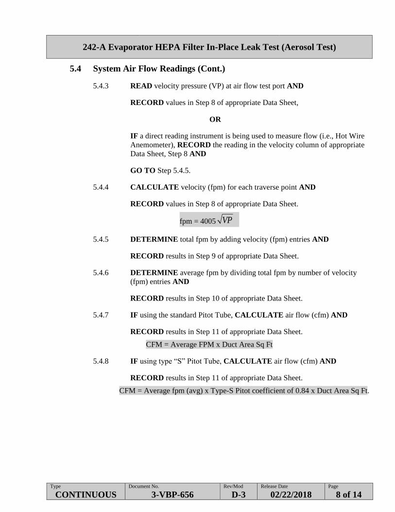
5.4 System Air Flow Readings (Cont.)
5.4.3 READ velocity pressure (VP) at air flow test port AND
RECORD values in Step 8 of appropriate Data Sheet,
OR
IF a direct reading instrument is being used to measure flow (i.e., Hot Wire
Anemometer), RECORD the reading in the velocity column of appropriate
Data Sheet, Step 8 AND
GO TO Step 5.4.5.
5.4.4 CALCULATE velocity (fpm) for each traverse point AND
RECORD values in Step 8 of appropriate Data Sheet.
fpm = 4005 VP
5.4.5 DETERMINE total fpm by adding velocity (fpm) entries AND
RECORD results in Step 9 of appropriate Data Sheet.
5.4.6 DETERMINE average fpm by dividing total fpm by number of velocity
(fpm) entries AND
RECORD results in Step 10 of appropriate Data Sheet.
5.4.7 IF using the standard Pitot Tube, CALCULATE air flow (cfm) AND
RECORD results in Step 11 of appropriate Data Sheet.
CFM = Average FPM x Duct Area Sq Ft
5.4.8 IF using type “S” Pitot Tube, CALCULATE air flow (cfm) AND
RECORD results in Step 11 of appropriate Data Sheet.
CFM = Average fpm (avg) x Type-S Pitot coefficient of 0.84 x Duct Area Sq Ft.
Page 9
242-A Evaporator HEPA Filter In-Place Leak Test (Aerosol Test)
Type
CONTINUOUS Document No.
3-VBP-656 Rev/Mod
D-3 Release Date
02/22/2018 Page
9 of 14
5.5 Aerosol Test Readings
NOTE - The following are operating pressures for the Aerosol Generators.
AEROSOL GENERATOR OPERATING PRESSURE
TDA-4B,TDA-6C,TDA-6D 18 to 22 psi
TDA-5B,TDA-5C 45 to 55 psi
TDA-6A N/A
5.5.1 IF system is equipped with test levers, PLACE levers in test position.
5.5.2 PERFORM a radiological contamination survey upon removal of any caps,
plugs, etc., on test ports.
5.5.3 RECORD aerosol generator pressure in Step 12 of appropriate Data Sheet.
5.5.4 ESTABLISH Aerosol Baseline Concentration (Cb) as follows:
5.5.4.1 INJECT aerosol into baseline injection port.
5.5.4.2 READ concentration at baseline sample port AND
RECORD in Step 13 of appropriate Data Sheet.
5.5.4.3 STOP injecting Aerosol.
5.5.4.4 MULTIPLY reading by photometer scale setting to determine
baseline concentration (Cb) AND
RECORD in Step 13 of appropriate Data Sheet.
Page 10
242-A Evaporator HEPA Filter In-Place Leak Test (Aerosol Test)
Type
CONTINUOUS Document No.
3-VBP-656 Rev/Mod
D-3 Release Date
02/22/2018 Page
10 of 14
5.5 Aerosol Test Readings (Cont.)
5.5.5 TEST Baseline and Penetration Background Concentrations (Bb, Bp) as
follows:
NOTE - Aerosol should be allowed to dissipate before taking background
readings.
5.5.5.1 ALLOW Aerosol to dissipate.
5.5.5.2 READ concentration at baseline sample port AND
RECORD in Step 14 of appropriate Data Sheet.
5.5.5.3 READ concentration at penetration sample port AND
RECORD in Step 14 of appropriate Data Sheet.
5.5.5.4 MULTIPLY readings by respective photometer scale settings to
determine background concentrations (Bb, Bp) AND
RECORD in Step 14 of appropriate Data Sheet.
5.5.6 TEST Aerosol Penetration Concentration (Cp) as follows:
5.5.6.1 INJECT aerosol into injection port.
5.5.6.2 READ concentration at penetration sample port AND
RECORD in Step 15 of appropriate Data Sheet.
5.5.6.3 STOP injecting Aerosol.
5.5.6.4 MULTIPLY reading by photometer scale setting to determine
downstream penetration concentration (Cp) AND
RECORD in Step 15 of appropriate Data Sheet.
5.5.7 REPEAT Steps 5.5.3 through 5.5.6 for a total of three trials.
5.5.8 IF more filters are to be tested, REPEAT Steps 5.5.2 through 5.5.7 for each
filter to be tested.
Page 11
242-A Evaporator HEPA Filter In-Place Leak Test (Aerosol Test)
Type
CONTINUOUS Document No.
3-VBP-656 Rev/Mod
D-3 Release Date
02/22/2018 Page
11 of 14
5.6 Remove Test Equipment and Restore Air System
5.6.1 WIPE test equipment upon removal.
5.6.2 SURVEY equipment upon removal.
5.6.3 INSTALL all caps, plugs, or instrumentation on test ports AND
RETURN any test levers to operating configuration.
5.6.4 SURVEY all equipment before removal from work area.
5.7 Aerosol Penetration Calculations
5.7.1 CALCULATE percent penetration (P) for each trial, using the formula
below AND
RECORD in Step 16 of appropriate Data Sheet.
b
p
C
CP 100
5.7.2 MARK results for each trial (Pass or Fail) in Step 17 of appropriate Data
Sheet as follows.
5.7.2.1 IF aerosol penetration is less than 0.05%, MARK Pass for that
trial.
5.7.2.2 IF aerosol penetration is equal to or greater than 0.05%, MARK
Fail for that trial.
5.7.3 IF any calculated penetration (P) is equal to or greater than 0.05%, NOTIFY
Operations Manager immediately AND
Facility Supervisor/FWS SIGN in Step 18 of appropriate Data Sheet.
Page 12
242-A Evaporator HEPA Filter In-Place Leak Test (Aerosol Test)
Type
CONTINUOUS Document No.
3-VBP-656 Rev/Mod
D-3 Release Date
02/22/2018 Page
12 of 14
5.8 Restoration
5.8.1 IF more filter trains are to be tested, REPEAT Section 5.1 through 5.8 for
those trains.
5.9 Acceptance Criteria
System performance is acceptable when percent penetration (P) for all three trials is less
than 0.05%.
Page 13
242-A Evaporator HEPA Filter In-Place Leak Test (Aerosol Test)
Type
CONTINUOUS Document No.
3-VBP-656 Rev/Mod
D-3 Release Date
02/22/2018 Page
13 of 14
5.10 Complete Field Work
5.10.1 PERFORM post-job radiation and contamination survey of work area to
verify radiological conditions are at pre-job levels or better AND
COMPLETE Steps 19 and 20 of appropriate Data Sheet.
5.10.2 Facility Supervisor/FWS ENSURE caps, plugs, and instrumentation, and test
levers are restored to original configuration AND
COMPLETE Step 21 of appropriate Data Sheet.
5.10.3 IF no deficiencies exist, ENTER N/A in Step 22 of appropriate Data Sheet
AND
GO TO Step 5.10.6.
5.10.4 Facility Supervisor/FWS RECORD in Step 22 of appropriate Data Sheet
work request numbers generated to correct any deficiencies identified by this
procedure.
5.10.5 Facility Supervisor/FWS NOTIFY Engineering of deficiencies AND
DOCUMENT in Step 22 of appropriate Data Sheet.
5.10.6 DOCUMENT RSR number in Step 23 of appropriate Data Sheet
5.10.7 WHEN field work is complete, INFORM Operations and Maintenance.
5.10.8 FORWARD Work Package to Vent and Balance.
Page 14
242-A Evaporator HEPA Filter In-Place Leak Test (Aerosol Test)
Type
CONTINUOUS Document No.
3-VBP-656 Rev/Mod
D-3 Release Date
02/22/2018 Page
14 of 14
5.11 Review
5.11.1 Vent and Balance reviewer CHECK data sheets for completeness and
legibility.
5.11.2 Vent and Balance reviewer COMPLETE Step 24 of appropriate Data Sheet
(print name, sign, and date).
5.11.3 FORWARD work package to Planner.
5.11.4 Planner PERFORM the following:
5.11.4.1 FORWARD copy of appendix to Environmental Compliance
(EC).
5.11.4.2 FORWARD copy of appendix to the Responsible Engineer.
5.12 Records
This procedure is performed within a work package, as such, the procedure in its entirety will be
maintained as a record per the Work Control process.
The record custodian identified in the company-level Records Inventory and Disposition
Schedule (RIDS) is responsible for record retention in accordance with
TFC-BSM-IRM_DC-C-02.