Page 1 2,500/4,000 LB Easy Riser Vertical Cable Feighner Lift CAUTION - PUT SAFETY FIRST 1. Before attempting to install or operate this lift, study and fully understand the proper operating procedures and safety precautions outlined in this owner's manual. 2. Never exceed the recommended weight capacity of your lift. The lifted weight will include hull, engine, fuel, battery, and added accessories or gear. Weigh your fully loaded boat at a certified scale to be absolutely sure of the total weight. 3. Do not allow anyone on, in, or under the lift while operating. 4. NOT COMPLYING WITH THE PROCEDURES AND PRECAUTIONS OUTLINED IN THIS MANUAL WILL INVALIDATE THE WARRANTY AND MAY RESULT IN PERSONAL INJURY OR DEATH. 5. If you have any questions about assembly, installation, operation or suitability of this product, contact an authorized dealer or The Feighner Co. directly at 1-517-541-0900.
CAUTION - PUT SAFETY FIRST 1. Before attempting to install or operate this lift, study and fully understand the proper operating procedures and safety precautions outlined in this owner's manual. 2. Never exceed the recommended weight capacity of your lift. The lifted weight will include hull, engine, fuel, battery, and added accessories or gear. Weigh your fully loaded boat at a certified scale to be absolutely sure of the total weight. 3. Do not allow anyone on, in, or under the lift while operating. 4. NOT COMPLYING WITH THE PROCEDURES AND PRECAUTIONS OUTLINED IN THIS MANUAL WILL INVALIDATE THE WARRANTY AND MAY RESULT IN PERSONAL INJURY OR DEATH. 5. If you have any questions about assembly, installation, operation or suitability of this product, contact an authorized dealer or The Feighner Co. directly at 1-517-541-0900.
Page 2
Vertical Boat Lift Hardware
24 – 3/8 x 4 ¼ HHC SS 4 – 3/8 x 3 ½ HHC SS 8 – 3/8 x 1 ¼ HHC SS 36 – 3/8 Nylon Insert Lock nut Brass 2 – ½ x 4 ½ HHC SS 7 – ½ Nylon Insert Lock nut Brass 9 – ½ Flat Washer SS
Keep all bolts loose at first. At the end use correct tools to tighten all nuts and
bolts.
Page 3
Introduction
Feighner vertical lifts will lift your boat up and out of the water for dockside storage. These lifts are designed to rest on a stable lake bottom. This lift performs will in low water conditions, fluctuating water depths up to four feet or when your boat requires mooring high out of the water. There are maximum allowable water depths depending on your leg lengths and situation. A properly positioned lift will provide safe, convenient, quick mooring for your boat.
The lift functions by turning the lift hand wheel clockwise to raise the lift. Properly position your boat in the lift wand it will raise with the lift rack. The wheel is turned counterclockwise to lower the lift.
Information in this manual is not all inclusive and cannot cover all unique situations. If you have questions about assembly, installation, operation or suitability of this product contact an authorized Feighner dealer or The Feighner Company at 517-541-0900
WARNINGS AND SAFETY
Your SAFETY is the most important issue related to this product. It is critical that all assemblers, installers and users read and fully understand the warnings and safety information contained throughout this manual before using this product.
SAFETY INSTRUCTIONS
Never exceed recommended weight capacity of your lift. The weight of your boat includes the hull, engine, fuel, gear, battery and added accessories; the dry weight reported by the manufacturer usually includes only the basic boat and engine. The boat manufacturers reported weights can be understated by 10-30%! This is before you add fuel, fluids, batteries, accessories, etc! Weigh your boat at a certified scale to be absolutely sure of the total weight. Your will be lifting 20-50% more that the reported dry weight when everything is considered.
Page 4
Assembly Instructions Your safety is the most important issue related to this product.
Wear protective gloves, clothing and eyewear when assembling and installing the lift.
Do not assemble, install or use this product if items are missing or damaged.
Fully read and understand each step before proceeding with that step.
Keep all bolts loose at first. At the end use correct tools to tighten all nuts and
bolts.
Step 1 Bolt on the Boat lift mud pads to the leveling legs using 1-3/8 x 3 ½ bolt with 1-3/8 Nylon Brass Nut. With the Adjustable holes facing opposing side of where the bolts connected. Do this for all 4 legs and insert into V-side frame.
Step 2 Attach one Bottom Beam to front both V Lift Sides. Using 3/8 x 4-1/4 HHC bolts with 3/8 Nylon Brass Nut
*NOTE: Bolt only five of the six holes at each corner at this time. The remaining hole will be used in a later step.
Page 5
Step 3 Attach one Bottom Beam to rear of both V Lift Sides. Using 3/8 x 4-1/4 HHC bolts with 3/8 Nylon Brass Nut *NOTE: Bolt only five of the six holes at each corner at this time. The remaining hole will be used in a later step.
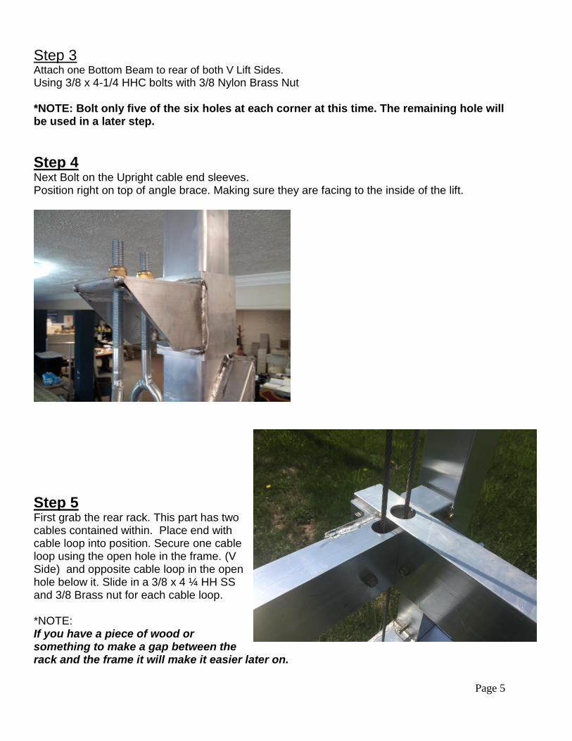
Step 4 Next Bolt on the Upright cable end sleeves. Position right on top of angle brace. Making sure they are facing to the inside of the lift.
Step 5 First grab the rear rack. This part has two cables contained within. Place end with cable loop into position. Secure one cable loop using the open hole in the frame. (V Side) and opposite cable loop in the open hole below it. Slide in a 3/8 x 4 ¼ HH SS and 3/8 Brass nut for each cable loop. *NOTE: If you have a piece of wood or something to make a gap between the rack and the frame it will make it easier later on.
Page 6
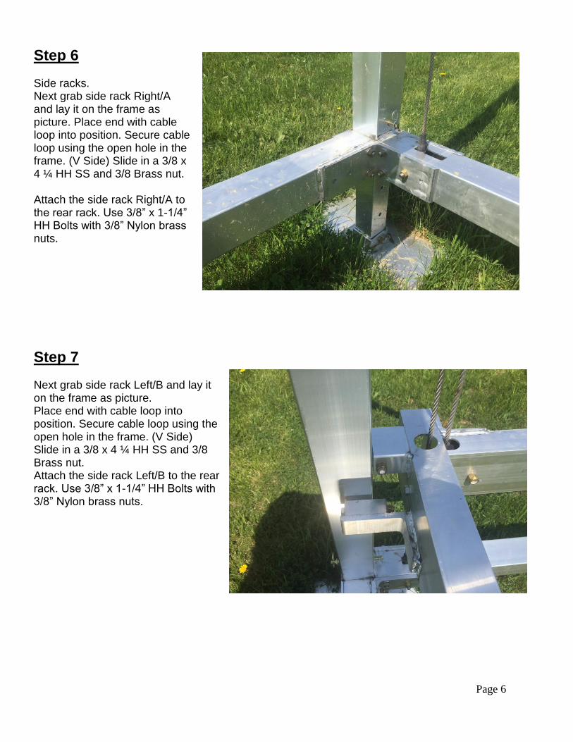
Step 6
Side racks. Next grab side rack Right/A and lay it on the frame as picture. Place end with cable loop into position. Secure cable loop using the open hole in the frame. (V Side) Slide in a 3/8 x 4 ¼ HH SS and 3/8 Brass nut. Attach the side rack Right/A to the rear rack. Use 3/8” x 1-1/4” HH Bolts with 3/8” Nylon brass nuts.
Step 7 Next grab side rack Left/B and lay it on the frame as picture. Place end with cable loop into position. Secure cable loop using the open hole in the frame. (V Side) Slide in a 3/8 x 4 ¼ HH SS and 3/8 Brass nut. Attach the side rack Left/B to the rear rack. Use 3/8” x 1-1/4” HH Bolts with 3/8” Nylon brass nuts.
Page 7
Step 8 Grab the Front/Winch rack. These will have the rollers welded to them and labeled. Place end with cable loop into position. Secure cable loop using the open hole in the frame. Slide in a 3/8 x 4/ ¼ HH SS and 3/8 Brass nut. Attach the winch rack to Left/B and Right/A rack. Use 3/8” x 1-1/4” HH Bolts with 3/8” Nylon brass nuts.
ATTACHING THE EYE BOLTS
Step 9 Starting with the post to the left of the winch. *THE WINCH POST WILL HAVE 2 HOLES DRILLED TOWARDS THE TOP Thread the eye bolt into the top bracket. This eye bolt sleeve will only have 1 hole in it. (picture A) The other two posts opposite side of the winch will have 2 cables in each bracket. (Shown in picture B) Attach the eye bolts with ½” Nylon Brass nuts and ½” SS Flat washer. Leave about a ½’ of thread beyond the nut. Final adjustments with the eye bolts with come later.
Picture A Picture B
Page 8
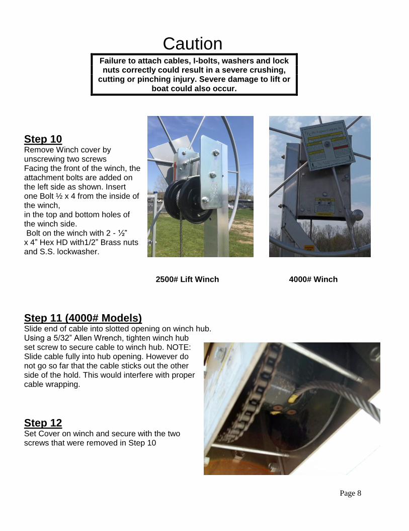
Caution Failure to attach cables, I-bolts, washers and lock nuts correctly could result in a severe crushing,
cutting or pinching injury. Severe damage to lift or boat could also occur.
Step 10 Remove Winch cover by unscrewing two screws Facing the front of the winch, the attachment bolts are added on the left side as shown. Insert one Bolt ½ x 4 from the inside of the winch, in the top and bottom holes of the winch side. Bolt on the winch with 2 - ½” x 4” Hex HD with1/2” Brass nuts and S.S. lockwasher. 2500# Lift Winch 4000# Winch
Step 11 (4000# Models) Slide end of cable into slotted opening on winch hub. Using a 5/32” Allen Wrench, tighten winch hub set screw to secure cable to winch hub. NOTE: Slide cable fully into hub opening. However do not go so far that the cable sticks out the other side of the hold. This would interfere with proper cable wrapping.
Step 12 Set Cover on winch and secure with the two screws that were removed in Step 10
Page 9
Step 13 The Winch wheel. On the rear side of the Wheel thread the Nylon Bolt 3/8 x .75 into the Round Hub enough so that it does not fall off Thread the Wheel clockwise on to shaft of the Winch. You must thread wheel all the way on winch shaft. The wheel hub must be fully against brake pad. Prior to securing wheel in place using the Bolt 5/16 x 1 Nyloc, stack a Spacer and/or up to six Washers Flat 5/16. Then place the stack in the bolt hole in the middle of the wheel. The stack should just barely protrude out of the center bolt hole. Remove one Washer Flat 5/16 at a time until the stack just barely protrudes out of the center hole. Once the correct number of Washers has been determined, secure the wheel in place using the Washer Flat Aluminum 1 1/8 and the Bolt 5/16 x 1 Nyloc Note: You should be able to slide a dime in the gap between sticker in the center of the wheel and the washer. The wheel should turn 1/8 to 1/4 turn prior to engaging the Washer Aluminum 1 1/8. Thread excess cable onto winch hub by turning wheel clockwise. Be sure cable wraps tight and uniformly on hub with each strand lying snuggly next to the adjacent strand. Keep tension on the cable by holding it tight when turning the wheel to develop a proper wrap. Do not allow cable to wind up loosely on hub.
INSTALLATION INSTRUCTIONS Do not under any circumstances, endanger yourself or risk damage to your lift or boat when installing. • Situations will widely vary between installation sites. Feighner Company. Recommends that your dealer or other trained boat lift installer train you and perform the initial installation. • W ear protective gloves, clothing and eyewear when assembling and installing the lift. • Do not assemble, install or use this product if items are missing or damaged. The following are guidelines or suggestions for installation:
STEP 1 Measure the water depth of the position you want to locate the lift. Measurements should be taken at both the projected position of the end nearest shore and end furthest from shore.
STEP 2 Before installing, adjust lift legs so the boat can float into position before raising, while still allowing a high enough position so the boat can be fully raised up and out of the water.
STEP 3 Carry, lift, roll, float or slide the lift into position alongside the dock. Ask your dealer about a wheel kit to allow your lift to be rolled into position.
Page 10
STEP 4 Ensure that your lift is level. Measure the distance from the top of the cross beam to the water surface. The distance at each of the four corners of the lift should be within two inches of each other. If they are not, adjust the legs accordingly. Note: If the lift legs will extend 3 feet or more, Feighner Boat Lift and Docks recommends deep water braces to stabilize and strengthen the lift. Ask your dealer for more information.
STEP 5 After loading and operating the lift pursuant to the operating instructions, remove the boat and recheck that the lift remains level.
CAUTION The lift must be resting on the water bottom in a level, secure and stable position for safe operation. An unstable lift installation could result in tipping of the lift during operation, causing damage to watercraft and a crushing or pinching injury to the operator or bystanders
.
OPERATING INSTRUCTIONS Now that you have installed and leveled the lift, you are ready to raise your boat for the first time. Prior to use, see to it that anyone who may use the lift looks upon the unit not as a toy but a piece of heavy equipment that deserves your respect and good judgment. • Before allowing anyone to operate the lift, be sure they fully understand the proper operating procedure. • Do not exceed maximum capacity of the lift; overloading may cause mechanical failure and serious personal injury. • Do not allow anyone who is in the water within six feet of the lift. • Do not allow anyone on, in or under the lift while operating. When operating the lift, the following procedures should be adhered to:
STEP 1 Be sure the lift rack and cradles or bunks are positioned below the water surface so they will not interfere with the boat floating into position.
STEP 2 Properly balance and center the boat on the lift prior to raising. The boat should be positioned with the center of gravity near the middle of the lift. For most rear engine
mounted boats, this requires you to position the boat somewhat forward in the lift.
STEP 3
Page 11
Turn wheel in direction of arrow (clockwise) to raise lift. Turning wheel and wrapping cable in wrong direction may cause fast spin down of wheel.
WARNING Stay clear of lifts (facing wheel) while operating. Do not allow anyone on, in or under lift. A cable or lift part failure can cause a sudden drop of boat, resulting in a crushing or falling injury or death!
CAUTION Do not touch wheel or attempt to stop it if fast spin down of wheel occurs. Placing hands or feet on spinning wheel can cause broken or cut limbs.
STEP 4 Carefully bring the lift up until the bunks or cradles have secured the boat. Then, stop the lift and check to see that the bunks or cradles have automatically positioned themselves to the shape of the hull, as they are designed to do. If so, continue bringing the boat out of the water until it is about one foot above the surface. Stop the lift again and check the stability of the lift, particularly to see that it is fairly level and will not topple over. Finally, continue lifting the boat while paying close attention to the positioning of the lift until it is at its desired height.
CAUTION When first using the boat lift after installation, the weight of the boat may cause the lift to settle and become unbalanced. Until you are certain the lift has stabilized, make sure people are not in the immediate vicinity of the lift.
CAUTIONS: 1. Do not over raise lift rack. Stop before top of rack hits cable loops attached to Eye Bolts. Over raising could cause damage to winch,cables or other parts. 2. Do not over lower rack so slack develops in cable. Doing this could cause cable to jump off winch spool. This may result in sloppy wrapping of cable next time you raise the lift, resulting in premature wear or cable breaking.Turn wheel down one or two turns past point when craft begins to float (This must always be at some point before lift rack is contacting rear bottom beam). Then turn wheel up slightly until clicking sound is heard to secure wheel position and brake on winch. 3. Properly cover your boat, or pull your boat's plug when the boat is in a raised position. Rain water accumulating in your bilge can quickly increase your gross weight over the capacity of the lift.
Page 12
4. Do not leave lift, or boat on lift, in water if ice formation is possible. Ice can severely damage your boatlift.
STEP 5 After loading and operating the lift, remove the boat and recheck that the lift remains level. (See Step 4 of the Installation Instructions.) If the lift is not level, the legs should be adjusted accordingly. Because the lift may settle and become unbalanced, the lift levelness should be rechecked two weeks after installation and periodically as needed.
STEP 6 If lift is without a boat in it for more than one day, raise the rack (pulleys) fully out of the water to help prevent corrosion of these parts. At all times, make sure the boat is stored high enough out of the water to avoid wave action against the hull. A moving boat as a result of wave action will damage the lift and can take the boat off the lift.
Monthly Checks Check cables for frays, corrosion or breaks at least once a month. A cable breaking while
boat is in lift could damage boat or lift. Severe bodily injury could also occur.
SAFETY MAINTENANCE 1. Inspect nuts and bolts for damage, wear or loose connections. Tighten or replace parts as needed. 2. Inspect lift frame, pulleys, winch and pivot points for unusual wear, damage or bent parts. Replace or repair as needed. 3. Check that the rack is level with the bottom frame of your lift. Cable stretching or settling of lift could require you to adjust nuts on Eye-Bolts. 4. Lubricate winch and wheel threads. Do not get lubricant on brake pads! Brake will fail and wheel will spin down if brake pads are lubricated. 5. Check and lubricate pulleys to ensure that they are turning freely. 6. Check Eye-Bolts to make sure they are not working themselves loose. Feighner dealers usually offer service visits. Please contact them if you are unable or unwilling to perform maintenance or service to lift.