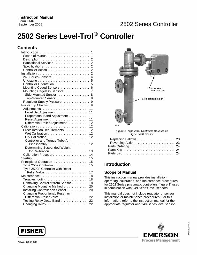
Scope of ManualThis instruction manual provides installation,operating, calibration, and maintenance proceduresfor 2502 Series pneumatic controllers (figure 1) usedin combination with 249 Series level sensors.
This manual does not include regulator or sensorinstallation or maintenance procedures. For thisinformation, refer to the instruction manual for theappropriate regulator and 249 Series level sensor.
Instruction ManualForm 1446September 2005 2502 Series Controller
2502 Series ControllerInstruction Manual
Form 1446September 2005
2
No person may install, operate, or maintain thisproduct without first � being fully trained andqualified in valve, actuator, and accessoryinstallation, operation, and maintenance, and �carefully reading and understanding the contents ofthis manual. If you have any questions about theseinstructions, contact your Fisher� sales office beforeproceeding.
Note
Neither Emerson�, Emerson ProcessManagement, Fisher, nor any of theiraffiliated entities assumesresponsibility for the selection, use,and maintenance of any product.Responsibility for the selection, use,and maintenance of any productremains with the purchaser andend-user.
DescriptionThe Type 2502 Level-Trol� controller described inthis manual provides proportional-plus-reset andproportional-plus-reset with differential relief valvecontrol. The controller output is a pneumatic signalthat operates a final control element. Thesecontrollers are designed to control liquid level, thelevel of interface between two liquids, or density(specific gravity). Each unit consists of a 249 Seriesliquid level sensor and a 2502 Series pneumaticcontroller.
Refer to the Principle of Operation section for a morecomprehensive discussion of how the Type 2502pneumatic controller operates.
Educational ServicesFor information on available courses for the Type2502 Series Level-Trol Controller, as well as avariety of other products, contact:
Emerson Process ManagementEducational Services, RegistrationP.O. Box 190; 301 S. 1st Ave.Marshalltown, IA 50158−2823Phone: 800−338−8155 or Phone: 641−754−3771Fax: 641−754−3431e-mail: [email protected]
Specifications
Table 1 gives general specifications for Type 2502Series controllers.
Controller-Sensor Action
The following controller description is for right-handmounting. Left-hand mounting produces an outputsignal with the opposite action. Figure 4 shows cagehead mounting positions.
For right-hand mounting:
� Direct Action—Increasing liquid or interfacelevel, or density, increases the output signal.
� Reverse Action—Decreasing liquid or interfacelevel, or density, increases the output signal. Afactory-supplied reverse-acting unit has the suffixletter R added to the type number.
Installation
The 2502 Series controllers are used in combinationwith 249 Series sensors, and unless orderedseparately, the controller will be attached to thesensor.
WARNING
Wear protective eyewear, gloves andclothing whenever possible whenperforming any installation operationsto avoid personal injury.
Check with your process or safetyengineer for any additional measuresthat must be taken to protect againstprocess media.
2502 Series ControllerInstruction ManualForm 1446September 2005
3
Table 1. Specifications
Available Configurations
Type 2502: A direct-acting controller whichprovides proportional-plus-reset controlType 2502C: A Type 2502 with a level indicatorassemblyType 2502F: A Type 2502 with a differential reliefvalveThese type numbered products are alsoavailable with reverse action. For example,Type 2502R, Type 2502CR, and 2502FR
Input Signal(1)
Liquid Level or Liquid-to-Liquid InterfaceLevel: From 0 to 100 percent of displacerlength—standard lengths for all sensors are 356mm (14 inches) or 813 mm (32 inches). Otherlengths available depending on sensorconstructionLiquid Density: From 0 to 100 percent ofdisplacement force change obtained with givendisplacer volume—standard volumes are 980 cm3
(60 inches3) for Types 249C and 249CP sensors,or 1640 cm3 (100 inches3) for most other 249Series sensors; other volumes availabledepending on construction
Output Signal(1)
0.2 to 1.0 bar (3 to 15 psig) or 0.4 to 2.0 bar (6 to30 psig)Action: Field reversible between direct(increasing liquid or interface level or specificgravity increases output pressure) and reverse(increasing liquid or interface level or specificgravity decreases output pressure)
Area Ratio of Relay Diaphragms
3:1
Supply Pressure Requirement
1.4 bar(2) (20 psig) for 0.2 to 1.0 bar (3 to 15 psig)output signal or 2.4 bar(2) (35 psig) for 0.4 to 2.0bar (6 to 30 psig) output signal
Maximum Supply Pressure(3)
3.4 bar (50 psig)
Supply Pressure Consumption(4)
At 1.4 bar (20 Psig)Minimum: 0.11 normal m3/h (4.2 scfh) atproportional band setting of 0 or 200 percentMaximum: 0.72 normal m3/h (27 scfh) atproportional band setting of 100 percentAt 2.4 bar (35 psig)Minimum: 0.2 normal m3/h (7 scfh) at proportionalband setting of 0 or 200 percentMaximum: 1.1 normal m3/h (42 scfh) atproportional band setting of 100 percent
Performance
Hysteresis: 0.6 percent of output pressurechange at 100 percent of proportional bandRepeatability(1): 0.2 percent of displacer lengthor displacement force changeDead Band(1): 0.05 percent of proportional bandor spanTypical Frequency Response(1): 4 Hz and90-degree phase shift at 100 percent ofproportional band with output piped to typicalinstrument bellows using 6.1 meters (20 feet) of6.4 mm (1/4 inch) tubingAmbient Temperature Error: �1.5 percent ofoutput pressure change per 50�F (28�C) oftemperature change at 100 percent ofproportional band when using sensor withstandard-wall N05500 (K-Monel) torque tube with249 Series sensorsReset(1): Adjustable from 0.01 to 74 minutes perrepeat (100 to 0.01 repeats per minute)Differential Relief (Type 2502F and 2502FRControllers Only): Adjustable from 0.1 to 0.48bar differential (2 to 7 psi) to relieve excessivedifference between proportional and resetpressures. Differential relief can be switchedbetween rising output pressure and falling outputpressure.
Standard Tubing Connections
1/4-inch NPT female
Maximum Working Pressures (Sensors Only)
Consistent with applicable ANSIpressure/temperature ratings
(continued)
2502 Series ControllerInstruction Manual
Form 1446September 2005
4
Table 1. Specifications (continued)
Hazardous Area Classification2502 Series controllers comply with therequirements of ATEX Group II Category 2 Gasand Dust
Operative Ambient Temperatures(3)
Standard Construction: 40 to 71�C (�40 to160�F�)High Temperature Construction: �18 to 104�C(0 to 220�F).See figure 2.
Declaration of SEP
Fisher Controls International LLC declares thisproduct to be in compliance with Article 3paragraph 3 of the Pressure Equipment Directive(PED) 97 / 23 / EC. It was designed andmanufactured in accordance with SoundEngineering Practice (SEP) and cannot bear theCE marking related to PED compliance.
However, the product may bear the CE markingto indicate compliance with other applicable ECDirectives.
1. Term defined in ISA Standard S51.1.2. Control and stability may be impaired if this pressure is exceeded.3. The pressure/temperature limits in this document, and any applicable standard or code limitation should not be exceeded.4. Normal cubic meters per hour (m3/hr) at 0�C and 1.01325 bar. Scfh=standard cubic feet per hour at 60�F and 14.7 psia .
USE INSULATOR (CAUTION! IF AMBIENT DEWPOINT ISABOVE PROCESS TEMPERATURE, ICE FORMATION MAYCAUSE INSTRUMENT MALFUNCTION AND REDUCEINSULATOR EFFECTIVENESS.)
0 20 40 60 80 100 120 140 160
0 10 20−18 −10 30 40 50 60 7071
593
500
400
300
200
100
00
400
800
1100
−20 −29
NO INSULATOR NECESSARY
AMBIENT TEMPERATURE (�C)
STANDARD CONTROLLER OR TRANSMITTER
AMBIENT TEMPERATURE (�F)
HEAT INSULATORREQUIRED
TOOHOT
NOTE: FOR SERVICE BELOW −29�C (−20�F) CONTACT FACTORY.
PR
OC
ES
S T
EM
PE
RA
TU
RE
( C
)
�
PR
OC
ES
S T
EM
PE
RA
TU
RE
( F
)
�
B1413-1/IL
0 20 40 60 80 100 120 140 200
0 10 20−18 −10 30 40 50 60 7093
593
500
400
300
200
100
00
400
800
1100
−20 −29
NO INSULATOR NECESSARY
AMBIENT TEMPERATURE (�C)
HIGH-TEMPERATURE CONTROLLER OR TRANSMITTER
AMBIENT TEMPERATURE (�F)
HEAT INSULATORREQUIRED
TOOHOT
PR
OC
ES
S T
EM
PE
RA
TU
RE
( F
)
�
180160
80 90
USE INSULATOR (CAUTION! IF AMBIENT DEWPOINT ISABOVE PROCESS TEMPERATURE, ICE FORMATION MAYCAUSE INSTRUMENT MALFUNCTION AND REDUCEINSULATOR EFFECTIVENESS.)
Figure 2. Guidelines for Use of Optional Heat Insulator Assembly
249 Series Sensors
� The Type 249, 249B, 249C, 249K, and 249Lsensors side-mount on the vessel with the displacermounted inside a cage (caged) outside the vessel.
� The Type 249BP and 249CP sensorstop-mount on the vessel with the displacer hangingdown into the vessel (cageless).
� The Type 249V sensor side-mounts on thevessel with the displacer hanging out into the vessel(cageless).
� The Type 249W sensor top-mounts on thevessel or on a customer supplied cage.
External sensors provide more stable operation thando internal sensors for vessels with internalobstructions or considerable internal turbulence.
WARNING
When replacing the sensor assembly,the displacer may retain process liquidor pressure. Personal injury orproperty damage due to suddenrelease of pressure, contact withhazardous liquid, fire, or explosion canbe caused by puncturing, heating, orrepairing a displacer that is retainingprocess pressure or liquid. Thisdanger may not be readily apparentwhen disassembling the sensor or
2502 Series ControllerInstruction ManualForm 1446September 2005
5
removing the displacer. Beforedisassembling the sensor or removingthe displacer, observe the morespecific warning provided in thesensor instruction manual.
UncratingUnless ordered separately, the controller will beattached to the sensor when shipped. Carefullyuncrate the assembly.
CAUTION
If the sensor has a thin-walled torquetube, always support the displacer ifthe travel stop must be removed. Athin-walled torque tube has a Tstamped on the sensor end flange (notvisible unless the controller isremoved from the sensor).
Note
Caged sensors have a rod and blockinstalled on each end of the displacerto protect the displacer in shipping.Remove these parts before installingthe sensor to allow the displacer tofunction properly.
Caged sensors will be shipped with the displacerinstalled in the cage. If the sensor is ordered with atubular gauge glass, the gauge glass will be cratedseparately and must be installed at the site. Becertain that the cage equalizing connections are notplugged with foreign material.
A caged sensor has a damping plate installed in thelower screwed or flanged connection to providemore stable operation. If the process liquid couldclog the plate opening with sediment, then removethe damping plate. For screwed connections, use a1/2-inch hexagon wrench to unscrew the dampingplate. For flanged connections, use a screwdriver topry the damping plate out of the flange.
1/4”-18 NPTSUPPLYCONNECTION
ADJUSTINGSCREW
DRAIN VALVE
LOCKNUT
1/4”-18 NPTOUTPUTCONNECTION VENT
PRESSUREREGULATOR
Figure 3. Pressure Connections
A cageless sensor is shipped with the displacerseparated from the sensor assembly. A displacerlonger than 813 mm (32 inches) is crated separately.A shorter displacer is crated with the sensor, but isnot attached to the displacer rod. Inspect thedisplacer and replace if it is dented. A dent mayreduce the pressure rating of the displacer.
Controller Orientation
A controller is to be mounted with the vent openingpointing downward as shown in figure 3. Thisorientation is necessary to ensure draining ofaccumulated moisture. The controller is attached tothe sensor in one or the other of the mountingpositions shown in figure 4: Right hand (with thecase to the right of the displacer when looking at thefront of the case) or left hand (with the case to theleft of the displacer). The mounting position can bechanged in the field if required; refer to theappropriate sensor manual for instructions.Changing this mounting position will changecontroller action from direct to reverse, or vice versa.
All caged sensors have a rotatable head. That is, thecontroller may be positioned at any of eight alternatepositions around the cage as indicated by thenumbers 1 through 8 in figure 4. To rotate the head,remove the head flange bolts and nuts and positionthe head as desired.
2502 Series ControllerInstruction Manual
Form 1446September 2005
6
AH9150−AA2613−2/IL
RIGHT-HAND MOUNTING
LEFT-HAND MOUNTING
Figure 4. Cage Head Mounting Positions
Mounting Caged Sensor
Note
The cage must be installed plumb sothat the displacer does not touch thecage wall. Should the displacer touchthe cage wall, the unit will transmit anerroneous output signal.
Note
If the controller is not mounted on thesensor, refer to the InstallingController on Sensor section. Thissection also provides instructions foradding a heat insulator to a unit.
Cage connections will normally be either 1-1/2 or2-inch screwed or flanged. Figure 5 shows thecombinations. With flanged connections, usestandard gaskets or other flat-sheet gasketscompatible with the process liquid. Spiral wound
A1271−2/IL
STYLE 1: TOPAND BOTTOM
STYLE 2: TOP AND LOWER SIDE
STYLE 2: UPPER AND LOWER SIDE
STYLE 2: UPPER SIDE AND BOTTOM
SCREWED: S1FLANGED: F1
SCREWED: S2FLANGED: F2
SCREWED: S3FLANGED: F3
SCREWED: S4FLANGED: F5
Figure 5. Cage Connection Styles
gaskets without compression-controlling centeringrings cannot be used for flanged connections.
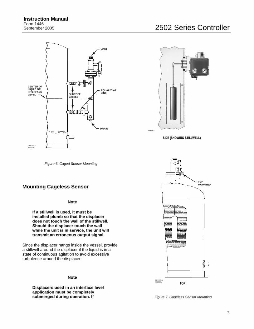
Mount the cage by running equalizing lines betweenthe cage connections and the vessel (figure 6). Ashutoff or hand valve with a 1-1/2 inch diameter orlarger port should be installed in each of theequalizing lines. Also install a drain between thecage and shutoff or hand valve whenever the bottomcage line has a liquid-trapping low point.
On liquid or interface level applications, position thesensor so that the line marked FLOAT CENTER onthe cage is located as close as possible to the centerof the liquid level or interface level range beingmeasured. Also consider installing a gauge glasseither on the vessel, or on the sensor cage (if thecage is tapped for a gauge).
2502 Series ControllerInstruction ManualForm 1446September 2005
7
DRAIN
CENTER OFLIQUID OR INTERFACELEVEL
DF5379-AA6771/IL
SHUTOFFVALVES
VENT
EQUALIZINGLINE
Figure 6. Caged Sensor Mounting
Mounting Cageless Sensor
Note
If a stillwell is used, it must beinstalled plumb so that the displacerdoes not touch the wall of the stillwell.Should the displacer touch the wallwhile the unit is in service, the unit willtransmit an erroneous output signal.
Since the displacer hangs inside the vessel, providea stillwell around the displacer if the liquid is in astate of continuous agitation to avoid excessiveturbulence around the displacer.
Note
Displacers used in an interface levelapplication must be completelysubmerged during operation. If
CF5380-AA3893/IL
TOPMOUNTED
SIDE (SHOWING STILLWELL)
W0645-1
TOP
Figure 7. Cageless Sensor Mounting
2502 Series ControllerInstruction Manual
Form 1446September 2005
8
displacers aren’t completelysubmerged they will not calibrate orperform properly. To obtain thedesired controller sensitivity mayrequire using either a thin-wall torquetube, an oversized displacer, or both.
Note
If the controller is not mounted on thesensor, refer to the InstallingController on Sensor section. Thissection also provides instructions foradding a heat insulator to a unit.
Attach a cageless sensor to a flanged connection onthe vessel as shown in figure 7. For interface orliquid level applications, install a gauge glass on thevessel.
CAUTION
If the displacer is to be inserted intothe vessel before being attached to thedisplacer rod, provide a suitablemeans of supporting the displacer toprevent it from dropping into thevessel and suffering damage.
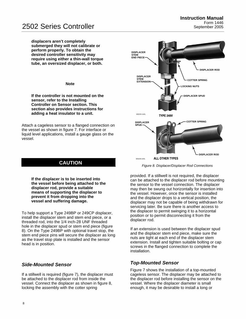
To help support a Type 249BP or 249CP displacer,install the displacer stem and stem end piece, or athreaded rod, into the 1/4 inch-28 UNF threadedhole in the displacer spud or stem end piece (figure8). On the Type 249BP with optional travel stop, thestem end piece pins will secure the displacer as longas the travel stop plate is installed and the sensorhead is in position.
Side-Mounted Sensor
If a stillwell is required (figure 7), the displacer mustbe attached to the displacer rod from inside thevessel. Connect the displacer as shown in figure 8,locking the assembly with the cotter spring
W0228-1A/IL
DISPLACER ROD
DISPLACERSPUD
ALL OTHER TYPES
COTTER SPRING
W0229-1A/IL
COTTER SPRING
DISPLACER ROD
LOCKING NUTS
DISPLACER SPUD
DISPLACERSTEMEXTENSION
DISPLACERSTEMEND PIECE
TYPE 249V
Figure 8. Displacer/Displacer Rod Connections
provided. If a stillwell is not required, the displacercan be attached to the displacer rod before mountingthe sensor to the vessel connection. The displacermay then be swung out horizontally for insertion intothe vessel. However, once the sensor is installedand the displacer drops to a vertical position, thedisplacer may not be capable of being withdrawn forservicing later. Be sure there is another access tothe displacer to permit swinging it to a horizontalposition or to permit disconnecting it from thedisplacer rod.
If an extension is used between the displacer spudand the displacer stem end piece, make sure thenuts are tight at each end of the displacer stemextension. Install and tighten suitable bolting or capscrews in the flanged connection to complete theinstallation.
Top-Mounted SensorFigure 7 shows the installation of a top-mountedcageless sensor. The displacer may be attached tothe displacer rod before installing the sensor on thevessel. Where the displacer diameter is smallenough, it may be desirable to install a long or
2502 Series ControllerInstruction ManualForm 1446September 2005
9
sectionalized displacer through the sensor headaccess hole after the sensor is installed on thevessel. Connect the displacer as shown in figure 8,locking the assembly with the cotter springsprovided. If a stem is used between the displacer asshown in figure 8, lock the assembly with the cottersprings provided. If a stem is used between thedisplacer spud and the stem end piece, make surethe nuts are tight at each end of the stem. Install andtighten suitable cap screws in the flanged connectionto complete the installation.
Regulator Supply Pressure
WARNING
Do not overpressurize any systemcomponent. Personal injury orproperty damage may occur due tosudden pressure release or explosion.To avoid damage, provide suitablepressure-relieving or pressure limitingdevices if supply pressure can exceedthe maximum supply pressure listed intable 1.
Personal injury or property damagemay occur from an uncontrolledprocess if the supply medium is notclean, dry, oil-free, or non-corrosivegas. While use and regularmaintenance of a filter that removesparticles larger than 40 microns indiameter will suffice in mostapplications, check with a Fisher fieldoffice and Industry Instrument airquality standards for used withcorrosive gas or if you are unsureabout the proper amount or method ofair filtration or filter maintenance.
Standard 2502 Series controllers come completewith supply and output pressure gauges and anintegrally mounted Type 67CFR regulator to reducesupply pressure from a maximum of 17.3 bar (250psig) to the 1.4 or 2.4 bar (20 or 35 psig) required.This regulator has built-in relief and a standard40-micron to remove particles from the supplysource.
The output pressure connection is on the back of thecontroller case (figure 3). Pipe the supply pressureto the in connection of the regulator mounted to thecase back. Provide a clean, dry, and noncorrosiveair or gas supply to the controller as follows:
After pressure connections have been made, turn onthe supply pressure and check all connections forleaks.
Prestartup Checks
WARNING
The following procedure requirestaking the controller out of service. Toavoid personal injury and propertydamage caused by an uncontrolledprocess, provide some temporarymeans of control for the processbefore taking the controller out ofservice.
Adjustment locations are shown in figure 9 unlessotherwise indicted. When performing the checksopen loop conditions must exist. To obtain open-loopconditions:
� make sure there is no process flow through thefinal control element, or
� disconnect the controller output signal line andplug the output connection.
During startup, it is necessary to change processlevels to position the displacer from its maximum toits minimum range of operations. Provide a means tochange the process level or interface. If the processvariable cannot be varied sufficiently, follow theinstructions in the Calibration section to simulate theprocess variable changes required for these checks.
Make sure that the RAISE LEVEL dial on thecontroller is mounted with the correct side facing out.The dial is printed on both sides with the arrow onone side pointing to the left and the arrow on theother side pointing to the right. Figure 9 shows thedial arrow positioned for a sensor that is mounted tothe left of the controller; the arrow points to the left. Ifthe sensor is to the right of the controller, remove thetwo mounting screws, turn the dial over so the arrowpoints to the right, then reinstall the mountingscrews.
On a controller with optional level indicator assemblythe travel indicator plate is printed on both sides. Ifthe sensor is to the left of the controller (right-handmounting), use the side of the plate that has thearrow pointing to the left. If displacer is to
2502 Series ControllerInstruction Manual
Form 1446September 2005
10
RESET ADJUSTMENT
W5637/IL/A
29A2834-C 30A8943-HA1933/IL
1E8731-C1E8732-CA1897-1/IL
21A6447-AA1903/IL
INSTRUCTION LABEL
RAISE LEVEL DIAL FORLEFT-HAND MOUNTING
TYPE 2502C LEVEL INDICATORWITH RIGHT-HAND MOUNTING
POINTER ASSEMBLY
TYPICAL RIGHT-HAND MOUNTED2502 SERIES CONTROLLER
DIFFERENTIAL RELIEF VALVEON BACK OF TYPE 2502 CASE
TRAVEL INDICATOR PLATEFOR LEFT HAND MOUNTING
MOUNTINGSCREWS
ADJUSTINGSCREW
Figure 9. Controller Adjustments
right of controller (left-hand mounting), use the sideof the plate that has the arrow pointing to the right.
1. Turn on the supply pressure and check that thecontroller supply gauge reads 1.4 bar (20 psig) for a0.2 to 1.0 bar (3 to 15 psig) output pressure range or2.4 bar (35 psig) for a 0.4 to 2.0 bar (6 to 30 psig)
output pressure range. If the pressure is incorrect,loosen the locknut of the filter/regulator (figure 3);turn the adjusting screw clockwise to increase orcounterclockwise to decrease pressure. Tighten thelocknut after setting the pressure.
2. Turn the reset control to .05 minutes per repeat.3. Locate the process variable at its minimum value(see table 2). Zero the proportional band and raise
2502 Series ControllerInstruction ManualForm 1446September 2005
11
level controls. Output pressure on direct-actingcontrollers should be greater than zero but less than0.2 bar (3 psig) for the 0.2 to 1.0 bar (3 to 15 psig)range or 0.4 bar (6 psig) for the 0.4 to 2.0 bar (6 to30 psig) range. For reverse-acting controllers, theoutput pressure should be greater than 1.0 bar (15psig) and less than 1.4 bar (20 psig) for the 0.2 to1.0 bar (3 to 15 psig) range or greater than 30 psig(2.0 bar) and less than 3.4 bar (35 psig) for the 0.4to 2.0 bar (6 to 30 psig) range. If these conditionsare not met recalibration may desired. On acontroller with indicator assembly, the pointer shouldbe over the low point on the indicator plate; slightadjustment might be necessary by loosening the hexnut (key 40, figure 14), shifting the pointer, andretightening the nut.
4. Set the raise level control as desired. Determinethe dial setting by moving the nameplate slide untilthe specific gravity on scale B is opposite thedisplacer volume on scale A. Choose the percentageof displacer length, as measured from the displacerbottom, that you desire the liquid or interface level tocover. Locate this percentage on scale D, and readup from this percentage to find the raise level dialsetting on scale C. For example, with a liquid levelapplication, a specific gravity of one (water service),and a 1.5 L (90-cubic-inch) displacer, move the slideso that 1.0 on scale B is over 90 on scale A. If it isdesired to have water level cover 50 per cent of thedisplacer length at the control point, read up from 50on scale D to find a 4.5 dial setting on scale C.
5. Relocate the process variable to the control pointdetermined in step 4. See if output pressureaccurately reflects the process variable. If not, see ifanother setting on the raise level dial brings theoutput pressure into agreement with the process.For example, with water level at 50 percent of theheight of the displacer, the output of a 0.2 to 1.0 bar(3 to15 psig) unit should be approximately 50percent of the way between 0.2 and 1.0 bar (3 and15 psig) or 0.6 bar (9 psig). If the new setting is morethan one graduation away from the settingdetermined in step 4, the unit would appear to be outof calibration and recalibration may be desirable.See the Calibration Procedure on page 14.
On a controller with level indicator, the pointershould reflect the magnitude of the process variable;for instance, with liquid or interface level covering 50percent of the displacer, the pointer should be in themiddle of the high-low scale. Slight plate adjustmentmight be necessary as described at the end of step 3.
6. If all prestartup checks are satisfactory proceedto the Startup section.
AdjustmentsController adjustments are provided in this section.Refer to figure 9 for adjustment locations.
Level Set AdjustmentTo perform the level adjustment, open the controllercover, loosen the knurled adjustment screw (seefigure 9), and rotate the adjustment lever around theRAISE LEVEL dial. To raise the fluid or interfacelevel, or increase density, rotate this knob in thedirection of the arrows. To lower the level ordecrease density, rotate the knob in the oppositedirection. This procedure is the same for both directand reverse action controllers. Tighten the knurledscrew.
Note
The raise level dial does not reflectactual fluid level in the tank or fluidlevel position on the displacer.
Proportional Band AdjustmentProportional band adjustment is made to change theamount of displacement force change required toobtain full output pressure change, by determiningthe percentage of pressure fed back to theproportional bellows. The adjustment is performedby opening the controller cover and turning thepercent proportional band knob (just below the raiselevel dial).
Reset AdjustmentTo adjust reset action (figure 9) turn the knobclockwise to decrease reset time (the minutes perrepeat). Turn the knob counterclockwise to increasethe minutes per repeat. Increasing the minutes perrepeat provides a slower reset action.
The reset rate adjustment dial is calibrated inminutes per repeat. By definition, this is the time inminutes required for the reset action to produce acorrection which is equal to the correction producedby proportional control action. This is, in effect, thetime in minutes required for the controller to increase(or decrease) its output pressure by an amountequal to a proportional increase (or decrease)caused by a change in control conditions.
2502 Series ControllerInstruction Manual
Form 1446September 2005
12
Differential Relief AdjustmentThe differential relief valve protrudes from the backof the controller case on a construction with an F inthe type number. Although normally factory-set torelieve when the differential between theproportional and reset bellows reaches 5 psi, thedifferential may be reduced down to 2 psi by turningthe adjustment screw clockwise or increased up to 7psi by turning the screw counterclockwise. Theminimum differential setting will yield the minimumset point overshoot during startup.
Depending on the characteristics of the process, therelief valve can be positioned so that the arrow caston the case points either to the letters RE (reset) orto the letter P (proportional) on the back of themanifold. To reposition the arrow, see figure 9.Remove the mounting screws. Reposition thedifferential relief valve to RE or P and reinstall themounting screws.
Calibration
Precalibration Requirements
Note
Calibration of a unit with a displacerdesigned for interface or densitycontrol must be conducted with thedisplacer completely submerged in aliquid of the specific gravity for whichthe unit was designed.
To calibrate a controller, it is necessary to place thedevice into operation. This may be done on thevessel with the actual service liquid. It may also bedone in the shop, but other means of obtaining adisplacement force change must be provided. Itmust be done in the shop if the process variable isnot available for calibration or if the process cannotbe varied for calibration. There are two methods ofadapting the calibration procedure to shopcalibration: wet and dry.
Wet CalibrationRemove the entire controller and sensor assemblyfrom the vessel. For caged sensors, pour the liquidinto the cage. For cageless sensors, suspend the
displacer to an appropriate depth in a liquid having aspecific gravity equal to that of the process liquid.
If necessary, use water for wet calibration in theshop. However, this procedure requirescompensation for the difference between the specificgravity of the water and that of the process liquids.For example, assume that the process liquid has aspecific gravity of 0.7 and that wet calibration withwater (specific gravity of 1.0) is desired. To simulatea process level of 50 percent of the input span, awater level of 35 percent is required (0.7/1.0 x 50percent = 35 percent).
Dry Calibration
Remove the controller and torque tube arm, as asingle unit, from the cage or vessel. Then, whereverthe standard calibration instructions in this manualrequire a specific process variable for input to thesensor, simulate that variable by suspending theproper weight (such as a can of sand) from the endof the displacer rod. Complete the followingController and Torque Tube Arm Disassembly andthe Determining Suspended Weight for Calibrationsections before proceeding to the calibrationprocedure.
Controller and Torque Tube ArmDisassembly
WARNING
To avoid personal injury from contactwith the process liquid, lower thevessel level below the sensor torquetube arm, or shut off the cageequalizing valves and drain the cagebefore proceeding. For closed vessels,release any pressure that may be inthe vessel before removing the sensorassembly.
When removing the displacer from the displacer rodor removing the controller and torque tube arm fromthe cage or vessel, refer to the appropriate sensorinstruction manual for assistance. The method ofremoving the displacer or torque tube arm andattached controller will vary with the type of sensor.
For a caged sensor with top equalizing connection, itmay be appropriate to remove the entire cage fromthe vessel before disassembling.
2502 Series ControllerInstruction ManualForm 1446September 2005
13
CAUTION
If the displacer is to be disconnectedfrom the displacer rod before thesensor assembly is removed from thecage or vessel, provide a means ofsupporting the displacer to prevent itfrom dropping and suffering damage.The spuds or stem end pieces on alldisplacers have holes suitable forinserting rods or other supports.
Additionally, a threaded rod may beinstalled into the 1/4-inch 28 UNFthreaded hole in the displacer spud orstem end piece of top-mountedcageless and all caged sensors. Forsome top-mounted sensors with longdisplacers, it may also be possible toremove the sensor through the accesshole in the sensor head.
For Type 249BP sensor with the travelstop, the stem end piece pins willsecure the displacer as long as thetravel stop plate is installed and thesensor head is in position.
Determining Suspended Weight forCalibration
CAUTION
To avoid overloading a torque tubesized for interface or densityapplications under dry conditions,consult your Fisher sales office for themaximum allowable substitute weightWs that can be used with yourparticular construction.
To determine the total weight that must besuspended from the displacer rod to simulate acertain condition of liquid level or specific gravity,solve the following equation:
Ws = Wd - [(0.0361) (V) (SP GR)]
where:
Ws = Total suspended weight in pounds (shouldnever be less than 0.5 pounds). For a unitwith a horizontal displacer, make sure thecenter of gravity of the substitute weight iswhere it would be on the actual displacer.
Note
For liquid level control only, simulatethe lower range limit of the input spanby suspending the displacer from thedisplacer rod. For other values of inputspan, remove the displacer andsuspend the appropriate weight asdetermined in the equation above.
Wd = Weight of the displacer, in pounds(determine by weighing displacer).
0.0361 = Weight of one cubic inch of water(specific gravity = 1.0), in pounds.
V = Volume of the displacer in cubic inches, thatwould be submerged at the level required bythe calibration procedure. Or,
V = π/4 (displacer diameter)2 x (length ofdisplacer submerged)
SP GR = Specific gravity of the process liquid atoperating temperature.
For interface level measurement, the equationbecomes:
V1 = Volume of the displacer submerged by thelighter liquid, in cubic inches.
Or,
V = π/4 (displacer diameter)2 x (length of thedisplacer submerged)
SP GR1 = Specific gravity of the lighter liquid atoperating temperature.
Vh = Volume of the displacer submerged by theheavier liquid, in cubic inches.
Or,
V = π/4 (displacer diameter)2 x (length of thedisplacer submerged)
SP GRh = Specific gravity of the heavier liquid atoperating temperature.
2502 Series ControllerInstruction Manual
Form 1446September 2005
14
Table 2. Minimum and Maximum Limits for Setting Process VariablesApplication Minimum Limit Maximum Limit
Liquid level Displacer must be completely out of liquid Displacer must be completely submerged in liquid
Interface Displacer must be completely submerged in the upperof two process liquids
Displacer must be completely submerged in the lowerof two process liquids
Density Displacer must be completely submerged in liquid havinghighest specific gravity expected
Displacer must be completely submerged in liquidhaving the lowest specific gravity expected
Calibration Procedure
WARNING
The following calibration procedurerequires taking the controller out ofservice. To avoid personal injury andproperty damage caused by anuncontrolled process, provide sometemporary means of control for theprocess before taking the controllerout of service.
Figure 9 shows adjustment locations for thefollowing steps, except as otherwise indicated. Whencalibrating, open loop conditions must exist. Oneway to obtain an open loop is to place the finalcontrol element into manual control or bypass it. Ifthere is no provision for manual control, shut downthe process. It is recommended that a test pressuregauge be installed in the controller output line forsubsequent calibration steps.
Several steps in these calibration procedures requiresetting the process variable at its minimum andmaximum limits according to table 2. Reverse-actingcontrollers produce the opposite response.
1. Connect a supply pressure source to thecontroller and provide a supply pressure suitable forthe sensing element range: 1.4 bar (20 psig) for a0.2 to 1.0 bar (3 to 15 psig) output pressure range or2.4 bar (35 psig) for a 0.4 to 2.0 bar (6 to 30 psig)output pressure range.
2. Rotate the reset knob to 0.01 minutes per repeat.
3. Rotate the proportional band knob to zero.
4. Set the liquid at the minimum limit (dry displacer).
5. Turn the raise level knob to zero.
6. Adjust the nozzle until output pressure is between0 and 0.2 bar for a 0.2 to 1.0 bar signal range (0 and3 psig for a 3 to 15 psig signal range) or 0 and 0.4bar for a 0.4 to 2.0 bar signal range (0 and 6 psig fora 6 to 30 psig signal range).
7. Set the liquid at the maximum limit (covereddisplacer).
8. Turn the raise level knob until the output pressureis 1.0 bar for a 0.2 to 1.0 bar signal range (15 psig fora 3 to 15 psig signal range) or 2.0 bar for a 0.4 to 2.0bar signal range (30 psig for a 6 to 30 psig signalrange).
9. The controller is within its calibration accuracy ifthe raise level knob is between the 9.0 and 10.0positions.
10. If the controller is out of calibration, adjust thecalibration adjuster as follows:
Note
Loosen the two calibration adjusterscrews (key 45, figure 14), and slidethe calibration adjuster (key 100, figure14) in the desired direction.
a. If output is below 1.0 bar for a 0.2 to 1.0 barsignal range (15 psig for a 3 to 15 psig signalrange) or 2.0 bar for a 0.4 to 2.0 bar signal range(30 psig for a 6 to 30 psig signal range), move theadjustor a small distance away from the pivot toincrease span. Then repeat steps 4 through 9.
b. If output is above 1.0 bar for a 0.2 to 1.0 barsignal range (15 psig for a 3 to 15 psig signalrange) or 2.0 bar for a 0.4 to 2.0 bar signal range(30 psig for a 6 to 30 psig signal range), move theadjustor a small distance toward the pivot todecrease span. Then repeat steps 4 through 9.
Note
If the controller cannot be calibrated,look for other problems as describedin the Troubleshooting section, suchas a nonperpendicular flapper-nozzlecondition, leaky connections, or abinding displacer rod. If none of thesetroubles is apparent, the displacer ortorque tube may be sized for a differentset of service conditions. Ensure thatthe displacer is sized correctly for theapplication.
2502 Series ControllerInstruction ManualForm 1446September 2005
15
StartupAdjustment locations are shown in figure 9.
1. Set the raise level control to the desired controlpoint as determined in prestartup checks step 4.
2. Set the percent proportional band control to 200.
3. Set the reset control to .05 minutes per repeat.
4. Slowly open the downstream and upstreammanual control valves in the pipeline and close themanual bypass valve if one is used.
5. With the controller set at the desired control point,narrow the proportional band until a cycling conditionexists. Then broaden the proportional band slightlyuntil stable control is obtained.
6. Adjust the reset control to obtain the highest resetsetting without introducing cycling.
7. To ensure that the optimum proportional bandand reset settings have been obtained, momentarilycreate a load upset. If cycling occurs, broaden theproportional band slightly and repeat the load upsetuntil stability is attained. In general, the narrowestproportional band and the highest reset setting thatwill not produce cycling will provide the best control.
Principle of OperationAll 2502 Series controllers use the same basicpressure-balanced relay with a yokeddouble-diaphragm assembly (figure 10). This relay isconnected so that supply pressure is fed to the inletside of the relay valve and to the fixed restriction.From this restriction, the air pressure goes into therelay chamber on the side of the large diaphragm,and to the nozzle. As long as there is no pressurechange on either diaphragm, the relay valve remainsin equilibrium with both the inlet and exhaust endsclosed.
The area ratio of the large diaphragm to the smalldiaphragm is 3 to 1. A 0.8 bar (12 psig) pressurechange on the small diaphragm need only bebalanced by a 0.3 bar (4 psig) change on the largediaphragm.
A change in liquid level, interface level, or densitychanges the buoyant force exerted on the sensordisplacer, which in turn imparts a rotary motionthrough the torque tube shaft. The rotary motion isapplied to the controller, which uses a nozzle,bellows, and pneumatic relay to convert the rotarymotion to a standard pneumatic output signal. The
output signal is sent to a final control element. Inconjunction with this control element, 2502-249Series controller-sensors are capable of bringing thecontrolled variable back to a specific control point allthe time.
The following descriptions show how the relay worksin conjunction with the standardproportional-plus-reset controller, and how thedifferential relief valve construction works.
Type 2502 ControllerAs long as inflow and outflow of the vessel areequal, the beam and flapper remain motionless andallow supply pressure to bleed through the nozzle asfast as it enters the relay through the fixedrestriction. A level or density change either raises orlowers the displacer and pivots the beam and flapperwith respect to the nozzle.
An increase in level or density with direct action, or adecrease with reverse action, moves the beam andflapper closer to the nozzle and restricts the escapeof supply pressure. This builds up the loadingdifferential on the side of the large diaphragm andopens the relay valve to supply pressure inflow.
On the other hand, a decrease in level or densitywith direct action, or an increase with reverse action,moves the beam and flapper away from the nozzleand permits supply pressure to bleed through thenozzle faster than it can enter through the fixedrestriction. This builds up the loading differential onthe side of the small diaphragm, and opens the relayvalve to exhaust loading pressure.
The three-way proportional valve can be opened andadjusted to allow some or all of the output pressurechange to feed back to the proportional bellows inorder to change the proportional band of thecontroller. This pushes the beam and flapperopposite the way it is being pivoted by the torquetube shaft, counteracting the pressure change in thenozzle and again stabilizing the relay diaphragmpressure differential. The relay valve shuts off andmaintains a new output pressure according to thechange in sensed displacer position.
A wide-open proportional valve permits feedback ofall the output change and produces 100 percentproportional response. Closing of this valveproduces smaller proportional responses, since partof the output change is vented through the valveexhaust and only the remainder is available toreposition the bellows.
2502 Series ControllerInstruction Manual
Form 1446September 2005
16
CD2114-ACJ4081-AC0313-1
PROPORTIONALBELLOWS
TORQUE TUBE SHAFT
FIXEDPIVOT
MOVABLEARM
PIVOTINGCROSSSPRINGS LEVEL SET
ADJUSTMENT
RESET BELLOWS
FIXEDPIVOT BEAM AND
FLAPPER
CAM
RESETVALVE
PROPORTIONALVALVE
FIXED RESTRICTION
EXHAUST ENDOF RELAYVALVE LARGE
DIAPHRAGMOF ASSEMBLY
SMALLDIAPHRAGMOF ASSEMBLY
INLET ENDOF RELAYVALVE
SUPPLY PRESSUREREGULATOR
DIRECT-ACTINGDIAPHRAGMCONTROL VALVE
VESSEL INFLOW
PROPORTIONAL PRESSURE
SUPPLY PRESSURE
OUTPUT PRESSURE
NOZZLE PRESSURE
RESET PRESSURE
EXHAUST
NOZZLE
Figure 10. Direct-Acting Right-Hand-Mounted 2502-249 Series Controller
2502 Series ControllerInstruction ManualForm 1446September 2005
17
CJ4081-ACU7387-BC0311-2
PROPORTIONAL PRESSURE
SUPPLY PRESSURE
OUTPUT PRESSURE
NOZZLE PRESSURE
RESET PRESSURE
EXHAUST
PROPORTIONALBELLOWS
FIXEDPIVOT
MOVABLE ARM
PIVOTINGCROSSSPRINGS
LEVEL SET ADJUSTMENT
RESETVALVE
PROPORTIONALVALVE
LARGE DIAPHRAGMOF ASSEMBLY
RESETBELLOWS
INNER CHAMBER
BEAM ANDFLAPPER
SMALLDIAPHRAGMOF ASSEMBLY
INLET ENDOF RELAY VALVE
OUTERCHAMBER
FIXED RESTRICTION
EXHAUST ENDOF RELAY VALVE
DIAPHRAGMASSEMBLYRESTRICTION
RELIEFVALVE
DIFFERENTIAL RELIEF VALVE
CAM
NOZZLE
RELIEFDIAPHRAGM
Figure 11. Type 2502F Controller with Differential Relief Valve
The reset valve can be adjusted to channel some orall of the proportional pressure into a reset bellowsthat opposes proportional bellows action. Thisautomatically dampens the effect of any proportionalovercorrection by a set amount per time interval, aslong as there is a deviation from the control point.
Figure 10 illustrates these principles at work in adirect-acting right-hand-mounted constructioncontrolling liquid inflow to a vessel, by means of adirect-acting diaphragm-actuated control valve.Nozzle positions and bellows connections would bereversed for direct action with left-hand mounting orreverse action with right-hand mounting.
Type 2502F Controller with DifferentialRelief ValveThis construction (figure 11) has a differential reliefvalve used to prevent proportional pressure fromexceeding reset pressure by more than a set value,a feature useful for intermittent control applications.Proportional valve output registers in the outerchamber of the relief valve as well as in theproportional bellows.
A sudden increase in the output pressure will causea rapid pressure increase in the proportional bellowsand in the outer relief valve chamber. If the outerchamber pressure exceeds that in the inner reliefvalve chamber by the amount of the relief pressure
2502 Series ControllerInstruction Manual
Form 1446September 2005
18
setting, the relief diaphragm will move off the orificein the relief valve, and the pressure in the outerchamber will bleed into the reset system. This actionprovides quick relief of excessive proportionalpressure and reduces the time required by thesystem to return to the control point.
Maintenance
The 2502 Series controllers are used in combinationwith 249 Series sensors.
WARNING
Wear protective eyewear, gloves andclothing whenever possible whenperforming maintenance to avoidpersonal injury.
Personal injury or property damagedue to sudden release of pressure,contact with hazardous liquid, fire, orexplosion can be caused bypuncturing, heating, or repairing adisplacer that is retaining processpressure or liquid. This danger maynot be readily apparent whendisassembling the sensor or removingthe displacer. Before disassemblingthe sensor or removing the displacer,observe the more specific warningprovided in the sensor instructionmanual.
Check with your process or safetyengineer for any additional measuresthat must be taken to protect againstprocess media.
Troubleshooting
When troubleshooting, open loop conditions mustexist unless otherwise stated. When monitoring theprocess variable, use the most accurate levelindicting device readily available. The output signalmeasuring device should have a correspondingaccuracy.
Table 3 lists some common operating faults, theirprobable causes, and corrective action.
Removing Controller from Sensor
WARNING
To avoid injury in the following steps,turn off the supply pressure andcarefully release any pressure trappedin the controller before breaking anypressure connection. Provide a bypassfor the control device if continuousoperation is required duringmaintenance.
Refer to figure 14 for key number locations, unlessotherwise indicated.
1. Disconnect the supply and output pressure tubingfrom the controller.
2. Loosen the hex nut (key 40) that secures theoperating arm base or pointer assembly (key 68 or51) to the torque tube rotary shaft. Do not lose thetwo link bearings (key 87, not shown).
CAUTION
If the hex nut has not been loosenedaccording to step 2, attempting toremove the controller from the sensormay bend the rotary shaft or operatingarm and linkage. Be careful that theback of the controller case or the heatinsulator does not drop down andbend the rotary shaft or shaftextension.
3. Remove any insulating tape from the jointbetween the controller case and the torque tubearm. Remove the four cap screws (key 39, figure 12)that hold the controller or heat insulator to the torquetube arm. Pull the case straight out from the torquetube arm, easing it over the shaft coupling (key 36,figure 12) if one is installed.
4. If the controller has a heat insulator, remove thebutton head cap screws (key 40). Remove fourwashers (key 53) and the insulator assembly (key35).
2502 Series ControllerInstruction ManualForm 1446September 2005
19
Table 3. Troubleshooting Chart for 2502 Series ControllersFault Possible Cause Check Correction
1. Process wanders or cyclesaround setpoint.
1.1 Proportional band or specificgravity adjustment incorrect orimproperly tuned control loop.
1.1 Insure the prestartupprocedures are completedcorrectly. Tune control loop.
1.1 If stable control cannot beattained and all other elements arefunctionally correct, examine otherpossible causes related to thecontroller/transmitter.
1.2 Use input pressure gauge tomonitor stability. Make sureregulator IN supply pressure iswithin limits.
1.2 Apply correct supply pressure.It is recommended to use oneregulator per instrument.
1.3 Sensor not plumb and is incontact with sidewall or leak indisplacer.
1.3 Check cage vessel and stillwellinstallation, or for leaking displacer.
1.3 Make sure the displacer anddisplacer rod hangs freely. Makesure linkage is tight. Replacedisplacer if leaking.
1.4 Relay malfunction. 1.4 Check for relay malfunction byusing the testing relay deadbandprocedure
1.4 Depress plunger to clean outthe fixed restriction. Replace orrepair relay using the procedure inthe Maintenance section.
2. Controller controlling off setpointor switching point.
2.1 Supply pressure not setcorrectly.
2.1 Make sure regulator supplypressure is set correctly. Make sureregulator IN supply pressure iswithin limits.
2.1 Reset the supply regulatorpressure. If the condition occursagain, rebuild or replace regulator.Provide a regulator input pressurewithin regulator limits.
2.2 Leak in the controller loop. 2.2 Use soap and water to checkfor internal and external leaks.
2.2 Replace or repair leaking partsas necessary.
2.3 Leaking displacer. 2.3 Insure the displacer is not fillingwith process fluid.
2.3 Refer to sensor maintenanceprocedures in the appropriatesensor instruction manual.
2.4 Flapper adjustment. 2.4 Insure the flapper is not looseon the torque tube shaft and iscentered on the nozzle.
2.4 Replace or tighten flapperassembly as necessary and/orcenter flapper on nozzle.
2.5 Process variable changed. 2.5 Insure the process variable hasnot changed from originalcalibration settings or, displacer notdesign specific gravity of process.
2.5 Change process variable backto original specification orrecalibrate. If necessary, providereplacement displacer of correctsize and recalibrate.
3. Controller cannot attain fulloutput range.
3.1 Supply pressure not setcorrectly.
3.1 Make sure supply pressure isset correctly. Make sure regulatorIN supply pressure is within limits.
3.1 Reset the regulator pressure. Ifproblem reoccurs, replace orrebuild the regulator. Insureregulator IN supply pressure iswithin limits at all operating levels.
3.2 Flapper adjustment. 3.2 Insure the flapper is not looseon the torque tube shaft and iscentered on the nozzle.
3.2 Replace or tighten flapperassembly as necessary and/orcenter flapper on nozzle.
3.3 Process variable changed. 3.3 Insure the process variable hasnot changed from originalcalibration settings or, fromdisplacer design specific gravity.
3.3 Change process variable backto original specification orrecalibrate. If necessary, providereplacement displacer of correctsize and recalibrate.
3.4 Relay malfunction. 3.4 Check for relay malfunction byusing the testing relay deadbandprocedure.
3.4 Depress plunger to clean outthe fixed restriction. Replace relayusing the procedure in theMaintenance section.
3.5 Leaking controller loop. 3.5 Use soap and water to checkfor internal and external leaks.
3.5 Replace or repair leaking partsas necessary.
4. Controller remains at full or zerooutput pressure.
4.1 Supply or output pressuregauge malfunction
4.1 Insure the pressure gauges areregistering correctly.
4.1 Replace pressure gauges. Usecorrective action given in section 3of this table.
4.2 Flapper adjustment. 4.2 Insure the flapper is not looseon the torque tube shaft. Insure theflapper is centered on the nozzle.
4.2 Replace or tighten flapperassembly as necessary and/orcenter flapper on nozzle.
2502 Series ControllerInstruction Manual
Form 1446September 2005
20
Changing Mounting Method
WARNING
To avoid injury from contact with theprocess liquid, lower the vessel levelbelow the torque-tube arm beforeproceeding. For closed vessels,release any pressure that may beabove the liquid. Also, be careful toavoid overloading a thin-wall torquetube and/or oversized displacer.
Refer to figure 14 for key number locations.
1. Remove the controller as described previously.
2. A controller is attached to the sensor in one orthe other of the mounting positions shown in figure4. Right hand mount is with the case to the right ofthe displacer when looking at the front of the case.Left hand mount is with the case to the left of thedisplacer. For a 249 Series sensor, remove thetorque tube arm from the sensor or vessel andreinstall the torque tube arm in the opposite positionaccording to the appropriate instruction manual.
3. Check the desired control action to determine if itis also necessary to reverse the controller action.The nozzle block and bellows tubing should bearranged in the proper position as shown in figure 13.
4. Remove the raise level dial, turn it over, andinstall it in the desired position. The arrow on it underthe word FLOAT should point toward the displacer.On a controller with indicator assembly, remove twoscrews (key 41, figure 14), turn the front plate (key54, figure 14) to the side that will have the floatarrow pointing toward the displacer, and secure theplate with the screws.
5. Install the controller according to the next section.
20A7423-C/DOC
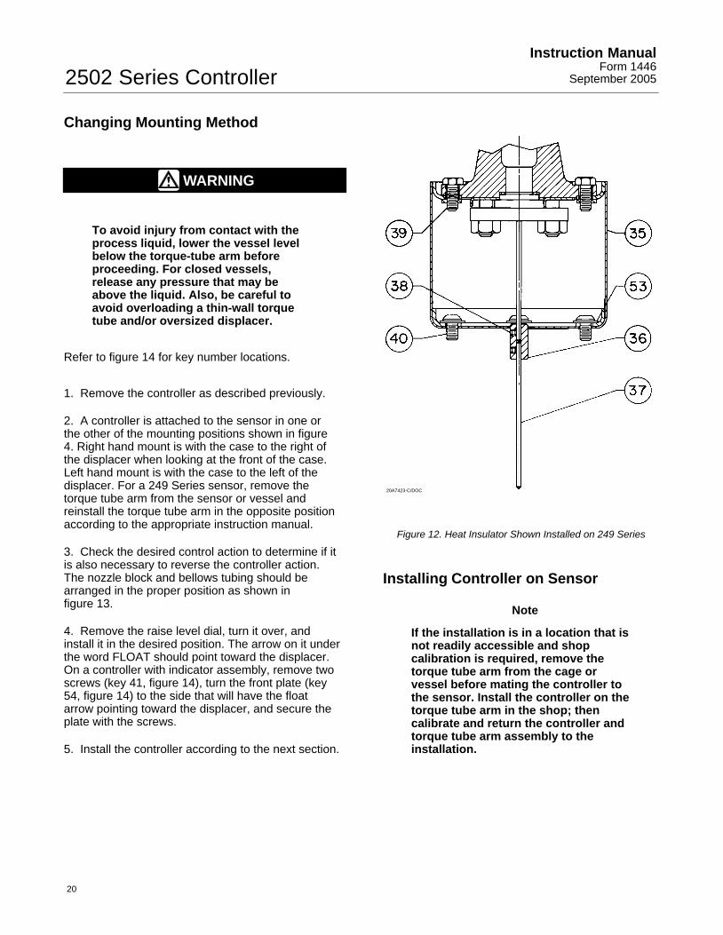
Figure 12. Heat Insulator Shown Installed on 249 Series
Installing Controller on Sensor
Note
If the installation is in a location that isnot readily accessible and shopcalibration is required, remove thetorque tube arm from the cage orvessel before mating the controller tothe sensor. Install the controller on thetorque tube arm in the shop; thencalibrate and return the controller andtorque tube arm assembly to theinstallation.
2502 Series ControllerInstruction ManualForm 1446September 2005
21
Perform step 1 only if adding a heat insulator toa unit that does not have one. Key numbers inthis step are shown in figure 12, unlessotherwise indicated.
1. To install the heat insulator, secure the shaftextension (key 37) to the torque tube assemblyrotary shaft with the shaft coupling (key 36). Tightenboth set screws (key 38), with the coupling centeredas shown in the figure. Then mount the insulatorassembly (key 35) on the controller case with fourwashers (key 53) and button-head cap screws (key40). Tighten the screws.
CAUTION
In the following step, avoid bendingthe torque tube rotary shaft of thetorque tube assembly. Bending or sideloading of this shaft could causeerroneous readings. Additionally,make sure the ball bearing assembly(key 12, figure 14) is removed from thecase (key 1, figure 14) to provideclearance when installing the case onthe sensor.
2. Remove the bearing assembly (key 12) from thecase (key 1).
3. Carefully slide the controller case straight in,guiding the bearing assembly (key 12), operatingarm base or pointer assembly (key 68 or 51, figure14) over the rotary shaft and easing an attachedheat insulator over the shaft coupling (key 36) ifnecessary. Secure the case or insulator to thetorque tube arm with the four cap screws (key 39).
Note
If a heat insulator is used, do notinsulate its exterior.
AV2323-AAV2322-AB0995-2/IL
SEALSCREW
SEALSCREWRING
SEALSCREW
SEALSCREWRING
FLAPPERHOOK
FLAPPERHOOK
PROPORTIONALTUBING
RESETTUBING
RESETTUBING
PROPORTIONALTUBING
RESETVALVE
RESETVALVE
SEALSCREWRINGS
SEALSCREWS
TO RELAY
TO RELAY
TOPROPORTIONALVALVE
TOPROPORTIONALVALVE
DIRECT ACTING—RIGHT HAND MOUNTINGREVERSE ACTING—LEFT HAND MOUNTING
REVERSE ACTING—RIGHT HAND MOUNTINGDIRECT ACTING—LEFT HAND MOUNTING
Figure 13. Nozzle, Flapper, and Tubing Arrangementsfor Various Actions and Mountings
2502 Series ControllerInstruction Manual
Form 1446September 2005
22
4. On a unit without a heat insulator, tape the jointbetween the case and torque tube arm to minimizethe entrance of atmospheric moisture around thetorque tube rotary shaft.
5. Install and tighten the bearing assembly (key 12,figure 14) in the case (key 1, figure 14). Secure theoperating arm base or pointer assembly to the rotaryshaft by tightening the hex nut (key 40, figure 14).Connect the supply and output pressure tubing andperform the calibration procedure.
Changing Proportional, Reset, orDifferential Relief Valve1. Remove the proportional band valve assembly(key 36, figure 14) by unscrewing it from the relaybase (key 23, figure 14). Install the desiredreplacement assembly, or a 1/8-inch NPT pipe pluginto the proportional band tapping if testing relaydead band.
2. To change the reset restriction valve assembly (key 91), remove the two mounting screws (key 182)located on the back side of case. Install thereplacement valve assembly, and reconnect thetubing connections.
3. Remove the differential relief valve assembly (key186, figure 14) by removing the two mountingscrews (figure 9) that anchor the valve to themanifold (key 184, figure 14). Install the valve withthe arrow pointing to the same letter(s) as beforeremoval, unless it is desired to change the reliefaction.
Testing Relay Dead Band1. Replace the proportional band adjustmentassembly with a 1/8-inch NPT pipe plug according tothe Changing Proportional, Reset, or DifferentialRelief Valve section.
2. Turn on the supply pressure and set it to1.4 or2.4 bar (20 or 35 psig).
3. By changing the process variable and adjustingthe raise level control, set the output pressure to 1.0or 2.0 bar (15 or 30 psig). While monitoring theoutput pressure, slowly change the process until anoutput pressure change can just be detected, andrecord the value of the process variable at thedetection point.
4. Change the process variable in the oppositedirection until another output pressure change canbe detected, and again record the value of theprocess variable. If the difference between the tworecorded values (the dead band) is more than 0.2percent of the maximum displacer length, the relaywill have to be replaced or repaired according to theChanging Relay and the Disassembling Relaysections.
5. Turn off the supply pressure, remove the pipeplug, and install the proportional band adjustmentassembly.
Changing Relay
The relay may be removed for cleaning orreplacement, and must be taken off to remove thelower bellows.
1. On a controller with indicator assembly, loosen thetwo lower screws of the relay case and slide out theindicator base plate (key 53, figure 14).
2. Disconnect the tubing (key 11, figure 14) from therelay.
3. Remove both mounting screws, the relay, and therelay gasket (keys 43, 34, and 22, figure 14).
4. Install a new gasket, the replacement relay ifnecessary, and both mounting screws. Reconnectthe tubing. On a controller with indicator assembly,slide the base plate under the two lower screws ofthe relay case, align the plate so that the pointer willread properly, and tighten the screws.
2502 Series ControllerInstruction ManualForm 1446September 2005
23
Replacing Bellows
Key numbers are shown in figure 14.
1. To gain access to the lower bellows, remove therelay according to the Changing Relay section.
2. Remove the upper and lower bellows framescrews (key 96) that hold both bellows assemblies tothe bellows frame. Unscrew each bellows from thespacer (key 98), being careful not to lose the O-ring(key 57, not shown) from the spacer end of thebellows.
3. Inspect each bellows and O-ring and replace ifnecessary, using an unpainted bellows for a 0.2 to1.0 bar (3 to 15 psig) range and a red bellows for a0.4 to 2.0 bar (6 to 30 psig) range. Be sure to installthe O-ring at the spacer end of the bellows.
4. Install each bellows by screwing it down over thestud (key 97, not shown) protruding from each endof the spacer. Secure with a bellows frame screw,and install the relay according to the Changing Relaysection.
5. Perform the calibration procedure and any othernecessary part of the calibration sequence.
Reversing Action
Note
The following procedure will benecessary to restore previous action ifthe mounting method has beenchanged. Key numbers are shown infigure 14.
1. Remove two screws (keys 63 and 64), two sealrings (key 55), and the nozzle block (key 101).Check seal ring condition and replace rings asnecessary.
2. Install the nozzle block, seal rings, and screws onthe opposite side of the beam as shown in figure 13.Disconnect the proportional band tubing (key 76)and one of the two pieces of reset tubing (key 75)from the bellows frame (key 94) and reconnect themin the proper orientation as shown in figure 13.
Note
Beam overtravel can jam the flapperagainst the nozzle if the following stepis not performed.
3. Remove the flapper screw (key 93), lockwasher(key 84), and flapper (key 60). Invert the flapper sothat the flapper hook is on the opposite side of thebeam from the nozzle (key 58), and secure with thelockwasher and screw.
4. Perform the calibration procedure and any othernecessary part of the calibration sequence.
2502 Series ControllerInstruction Manual
Form 1446September 2005
24
Parts Ordering
Whenever corresponding with your Fisher salesoffice about this equipment, always mention thecontroller type number and the serial number foundon the unit nameplate (figure 9). When orderingreplacement parts, also state the complete11-character part number of each required part asfound in the following parts list.
Note
Use only genuine Fisher replacementparts. Components that are notsupplied by Fisher should not, underany circumstances, be used in anyFisher instrument. Use of componentsnot supplied by Fisher will void yourwarranty, might adversely affect yourthe performance of the instrument, andmight jeopardize worker andworkplace safety.
Note
Neither Emerson, Emerson ProcessManagement, Fisher, nor any of theiraffiliated entities assumesresponsibility for the selection, useand maintenance for any product.Responsibility for the selection, use,and maintenance of any productremains with the purchaser andend-user.
Parts KitsDescription Part Number
Controller Parts KitContains keys 12, 15, 21, 24, 38, 55, 57, 58, 60, 62, 63, 64,77, 79, 84, 86, 87, 93, 101, and 187Standard Temperature R2502X00L52High Temperature R2502X00H52
Relay Replacement KitContains keys 22, 43, and the relay assembly
Standard Temperature RRELAYX0L22High Temperature RRELAYX0H22
Heat Insulator Parts KitContains keys 35, 36, 37, 38, 39, 40, and 53 R2500XH0012
187 Sleeve, plastic 16A0976X012188* 0-Ring, Types 2502F and 2502FC 1C8538X0132215 Nameplate, metal
Pipe Plug, Types 2502 and 2502C 1D754828982
*Recommended spare parts
2502 Series ControllerInstruction ManualForm 1446September 2005
27
2502 Series ControllerInstruction Manual
Form 1446September 2005
28
Fisher Marshalltown, Iowa 50158 USACernay 68700 France Sao Paulo 05424 BrazilSingapore 128461
Emerson Process Management
www.Fisher.com
The contents of this publication are presented for informational purposes only, and while every effort has been made to ensure their accuracy, they arenot to be construed as warranties or guarantees, express or implied, regarding the products or services described herein or their use or applicability.We reserve the right to modify or improve the designs or specifications of such products at any time without notice.
Neither Emerson, Emerson Process Management, Fisher, nor any of their affiliated entities assumes responsibility for the selection, use and maintenance of any product. Responsibility for the selection, use and maintenance of any product remains with the purchaser and end-user.
�Fisher Controls International LLC 1977, 2005; All Rights Reserved Printed in USA
Level-Trol and Fisher are marks owned by Fisher Controls International LLC, a member of the Emerson Process Management business division ofEmerson Electric Co. Emerson and the Emerson logo are trademarks and service marks of Emerson Electric Co. All other marks are the propertyof their respective owners.