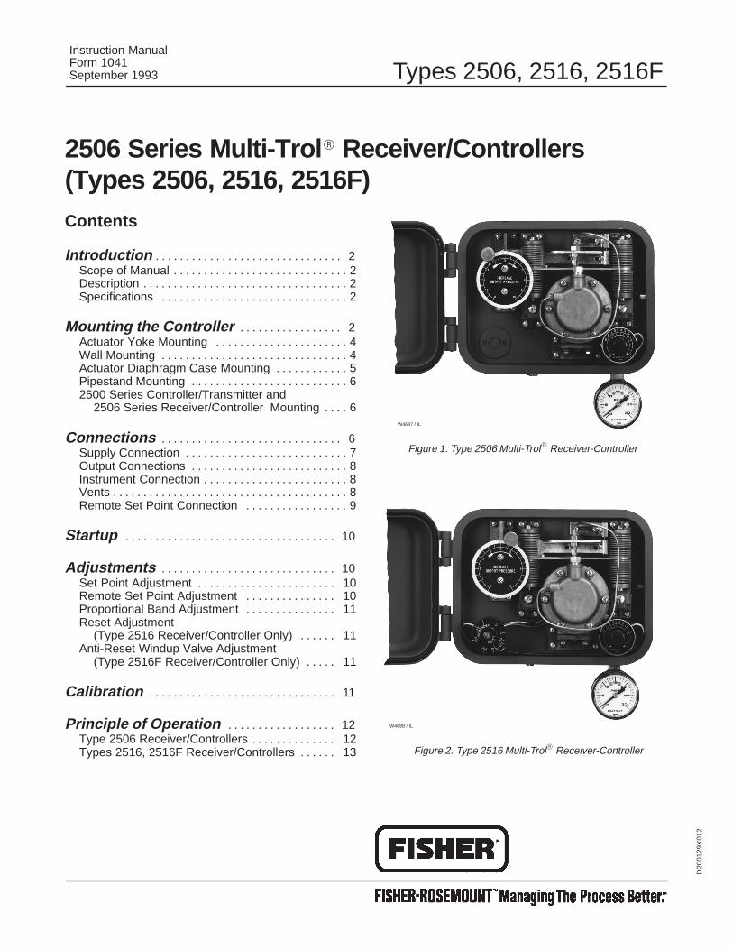
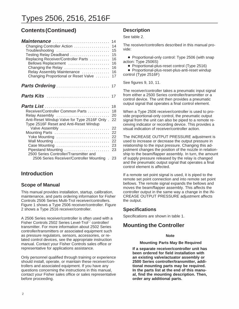
Scope of ManualThis manual provides installation, startup, calibration,maintenance, and parts ordering information for FisherControls 2506 Series Multi-Trol receiver/controllers.Figure 1 shows a Type 2506 receiver/controller. Figure2 shows a Type 2516 receiver/controller.
A 2506 Series receiver/controller is often used with aFisher Controls 2502 Series Level-Trol controller/transmitter. For more information about 2502 Seriescontroller/transmitters or associated equipment suchas pressure regulators, sensors, accessories, or re-lated control devices, see the appropriate instructionmanual. Contact your Fisher Controls sales office orrepresentative for applications assistance.
Only personnel qualified through training or experienceshould install, operate, or maintain these receiver/con-trollers and associated equipment. If you have anyquestions concerning the instructions in this manual,contact your Fisher sales office or sales representativebefore proceeding.
DescriptionSee table 2.
The receiver/controllers described in this manual pro-vide:
� Proportional-only control: Type 2506 (with snapaction: Type 2506S)� Proportional-plus-reset control (Type 2516)� Proportional-plus-reset-plus-anti-reset windup
control (Type 2516F)
See figures 9, 10, 11.
The receiver/controller takes a pneumatic input signalfrom either a 2500 Series controller/transmitter or acontrol device. The unit then provides a pneumaticoutput signal that operates a final control element.
When a Type 2506 receiver/controller is used to pro-vide proportional-only control, the pneumatic outputsignal from the unit can also be piped to a remote re-ceiving indicator or recording device. This provides avisual indication of receiver/controller action.
The INCREASE OUTPUT PRESSURE adjustment isused to increase or decrease the output pressure inrelationship to the input pressure. Changing this ad-justment changes the position of the nozzle in relation-ship to the beam/flapper assembly. In turn, the amountof supply pressure released by the relay is changedand the pneumatic output signal that operates a finalcontrol element is affected.
If a remote set point signal is used, it is piped to theremote set point connection and into remote set pointbellows. The remote signal expands the bellows andmoves the beam/flapper assembly. This affects thecontroller output in the same way a change in the IN-CREASE OUTPUT PRESSURE adjustment affectsthe output.
SpecificationsSpecifications are shown in table 1.
Mounting the Controller
Note
Mounting Parts May Be Required
If a separate receiver/controller unit hasbeen ordered for field installation withan existing valve/actuator assembly or2500 Series controller/transmitter, addi-tional mounting parts may be required.In the parts list at the end of this manu-al, find the mounting description. Then,order any additional parts.
Types 2506, 2516, 2516F
3
Table 1. Specifications
Available Configurations
For additional information, refer to table 2
Type 2506: A receiver/controller(1) that is set foreither proportional or snap action (S) control or foreither direct or reverse (R) action
Type 2516: A Type 2506 that also provides propor-tional-plus-reset control
Type 2516F: A Type 2516 that also provides anti-reset windup control
Input Signal Range (2)
From a transmitter or control device, a signal of 3 to15 psig (0.2 to 1.0 bar) or 6 to 30 psig (0.4 to 2.0bar) is required depending on receiver/controllerrange. Refer to receiver/controller nameplate forspecific range
Output Signal Range (2,3)
See table 3
Output Action
Direct Action: An increasing fluid, interface level,or density increases output pressure or,
Reverse Action: An increasing fluid, interface lev-el, or density decreases output pressure
Remote Set Point Signal Range
From a control device, provide a remote set pointsignal that is 3 to 15 psig (0.2 to 1.0 bar) or 6 to 30psig (0.4 to 2.0 bar) that matches the receiver/con-troller input signal range.
Supply Pressure (2)
Normal Operating Pressure: See table 3
Maximum Pressure to Prevent Internal PartRupture: 50 psig (3.4 bar)
Steady State Air Consumption (3)
See table 3
Proportional Band (2) Reset (2), and Anti-ResetWindup
See table 2 and the Changing Controller Action pro-cedure
Performance
Hysteresis: 0.6 percent of output pressure changeat 100 percent of proportional band for Type 2506proportional receiver/controllers only
Standard Supply and Output Pressure Gauge Indi-cations
See table 3
Standard Tubing Connections
All connections are 1/4-inch NPT female
Operative Ambient Temperature Limits
Standard: –40 to 160°F (–40 to 71°C)
High Temperature: 0 to 220°F (–18 to 104°C)
Approximate Weight
10 Pounds (4.54 kg)
1. Receiver/controllers are field adjustable between direct or reverse action. If the receiver/controller is set for reverse action at the factory, an R suffix will appear in the type number.Receiver/controllers are field-adjustable between proportional and snap action.If the receiver/controller is set for snap action at the factory, an S suffix appears in the type number.2. These terms are defined in ISA Standard S51.1-1979. 3. Scfh at 60°F, 14.7 psia (m3/hr at 0°C, 1.01325 bar absolute).
Proportional Band: Adjustable from 0 to 100% of transmitter signal.
3 to 15 psig(0.2 to 1.0 bar) or6 to 30 psig(0.4 to 2.0 bar)
Snap action control(Type 2506S)
Snap Action: Control output is at 0 or 100% of input supply pressure. Switching depends onposition of sensor and is adjustable.
0 to 20 psig(0 to 1.4 bar) or0 to 35 psig(0 to 2.4 bar)
Proportional-plus-resetcontrol (Type 2516)
Proportional Band: Adjustable from 0 to 200% of transmitter signal. Recommended setting isfrom 20 to 200%.Reset: Adjustable form 0.01 to 74 minute per repeat with standard reset valve setting. 3 to 15 psig
Proportional Band: Adjustable from 0 to 200% of transmitter signal. Recommended setting isfrom 20 to 200%.Reset: Adjustable from 0.01 to 74 minute per repeat with standard reset valve setting.Differential Relief: Provides relief when output pressure falls or when output pressure risesdepending on valve adjustment.
3 to 15 sig(0.2 to 1.0 bar) or6 to 30 psig(0.4 to 2.0 bar)
1. Proportional control is continuously active between 0 and 100 percent of the transmitter signal span. Differential gap provides snap action between 0 and 100 percent of thetransmitter signal. Do not use reset controllers in snap action.
Types 2506, 2516, 2516F
4
Table 3. Supply Pressure Data
OUTPUT SIGNALRANGE
STANDARD SUPPLYAND OUTPUT
PRESSURE GAUGEINDICATIONS(1)
NORMALOPERATING
SUPPLYPRESSURE(2)
AIR CONSUMPTION ATNORMAL OPERATINGSUPPLY PRESSURE
INDICATIONS(1)Psig Bar Minimum (3) Maximum (4)
3 to 15 psig (0.2 to 1.0 bar) 0 to 30 psig 20 1.4 4.2 scfh(5) 27 scfh(5)
6 to 30 psig (0.4 to 2.0 bar) 0 to 60 psig 35 2.4 7 scfh(5) 42 scfh(5)
1. Consult your Fisher Controls sales office or representative for gauges calibrated inother units of measurement.2. Control and stability may be impaired if this pressure is exceeded.3. At zero or maximum proportional band or span setting.
4. At setting in middle of proportional band or span range.5. If air consumption is desired in normal m3/hr at 0°C and 1.01325 bar, multiply scfhby 0.0268.
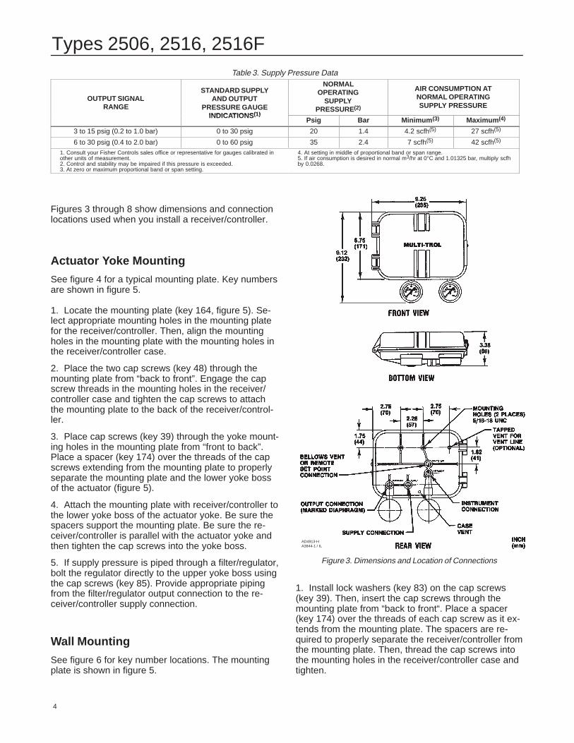
Figures 3 through 8 show dimensions and connectionlocations used when you install a receiver/controller.
Actuator Yoke Mounting
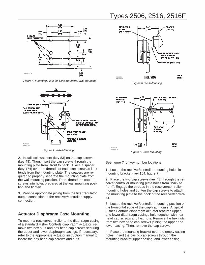
See figure 4 for a typical mounting plate. Key numbersare shown in figure 5.
1. Locate the mounting plate (key 164, figure 5). Se-lect appropriate mounting holes in the mounting platefor the receiver/controller. Then, align the mountingholes in the mounting plate with the mounting holes inthe receiver/controller case.
2. Place the two cap screws (key 48) through themounting plate from “back to front”. Engage the capscrew threads in the mounting holes in the receiver/controller case and tighten the cap screws to attachthe mounting plate to the back of the receiver/control-ler.
3. Place cap screws (key 39) through the yoke mount-ing holes in the mounting plate from “front to back”.Place a spacer (key 174) over the threads of the capscrews extending from the mounting plate to properlyseparate the mounting plate and the lower yoke bossof the actuator (figure 5).
4. Attach the mounting plate with receiver/controller tothe lower yoke boss of the actuator yoke. Be sure thespacers support the mounting plate. Be sure the re-ceiver/controller is parallel with the actuator yoke andthen tighten the cap screws into the yoke boss.
5. If supply pressure is piped through a filter/regulator,bolt the regulator directly to the upper yoke boss usingthe cap screws (key 85). Provide appropriate pipingfrom the filter/regulator output connection to the re-ceiver/controller supply connection.
Wall Mounting
See figure 6 for key number locations. The mountingplate is shown in figure 5.
Figure 3. Dimensions and Location of Connections
AD4913-HA3844-1 / IL
1. Install lock washers (key 83) on the cap screws(key 39). Then, insert the cap screws through themounting plate from “back to front“. Place a spacer(key 174) over the threads of each cap screw as it ex-tends from the mounting plate. The spacers are re-quired to properly separate the receiver/controller fromthe mounting plate. Then, thread the cap screws intothe mounting holes in the receiver/controller case andtighten.
Types 2506, 2516, 2516F
5
Figure 4. Mounting Plate for Yoke Mounting, Wall Mounting
IC2218-E / IL
Figure 5. Yoke Mounting
AD4913-HA3848-1 / IL
2. Install lock washers (key 83) on the cap screws(key 48). Then, insert the cap screws through themounting plate from ‘‘front to back’’. Place a spacer(key 174) over the threads of each cap screw as it ex-tends from the mounting plate. The spacers are re-quired to properly separate the mounting plate fromthe wall mounting position. Then, thread the capscrews into holes prepared at the wall mounting posi-tion and tighten.
3. Provide appropriate piping from the filter/regulatoroutput connection to the receiver/controller supplyconnection.
Actuator Diaphragm Case Mounting
To mount a receiver/controller to the diaphragm casingof a standard Fisher Controls diaphragm actuator, re-move two hex nuts and hex head cap screws securingthe upper and lower diaphragm casings. If necessary,refer to the appropriate actuator instruction manual tolocate the hex head cap screws and nuts.
2. Place the two cap screws (key 48) through the re-ceiver/controller mounting plate holes from ‘‘back tofront’’. Engage the threads in the receiver/controllermounting holes and tighten the cap screws to attachthe mounting plate to the back of the receiver/control-ler.
3. Locate the receiver/controller mounting position onthe horizontal edge of the diaphragm case. A typicalFisher Controls diaphragm actuator features upperand lower diaphragm casings held together with hexhead cap screws and hex nuts. Remove the hex nutsfrom two hex head cap screws joining the upper andlower casing. Then, remove the cap screws.
4. Place the mounting bracket over the empty casingholes. Insert the casing cap screws through themounting bracket, upper casing, and lower casing.
Types 2506, 2516, 2516F
6
Add the nuts and tighten to secure the mountingbracket with receiver/controller to the casing.
5. If supply pressure is piped through a filter/regulator,the regulator may be attached in one of two locations:
� Attach the regulator directly to the upper yokeboss using the cap screws (key 85) for yoke mounting.
� Attach the regulator to the casing using a mount-ing bracket (key 177). The mounting bracket for theregulator is the same as the mounting bracket for thereceiver/controller. Follow steps 1 through 4 to mountthe regulator.
6. Connect the filter/regulator output connection to thereceiver/controller supply connection.
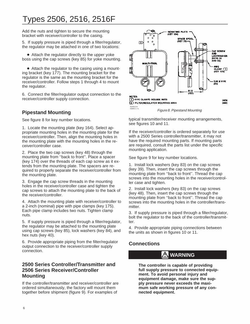
Pipestand MountingSee figure 8 for key number locations.
1. Locate the mounting plate (key 164). Select ap-propriate mounting holes in the mounting plate for thereceiver/controller. Then, align the mounting holes inthe mounting plate with the mounting holes in the re-ceiver/controller case.
2. Place the two cap screws (key 48) through themounting plate from ‘‘back to front’’. Place a spacer(key 174) over the threads of each cap screw as it ex-tends from the mounting plate. The spacers are re-quired to properly separate the receiver/controller fromthe mounting plate.
3. Engage the cap screw threads in the mountingholes in the receiver/controller case and tighten thecap screws to attach the mounting plate to the back ofthe receiver/controller.
4. Attach the mounting plate with receiver/controller toa 2-inch (nominal) pipe with pipe clamps (key 175).Each pipe clamp includes two nuts. Tighten clampnuts.
5. If supply pressure is piped through a filter/regulator,the regulator may be attached to the mounting plateusing cap screws (key 85), lock washers (key 84), andhex nuts (key 40).
6. Provide appropriate piping from the filter/regulatoroutput connection to the receiver/controller supplyconnection.
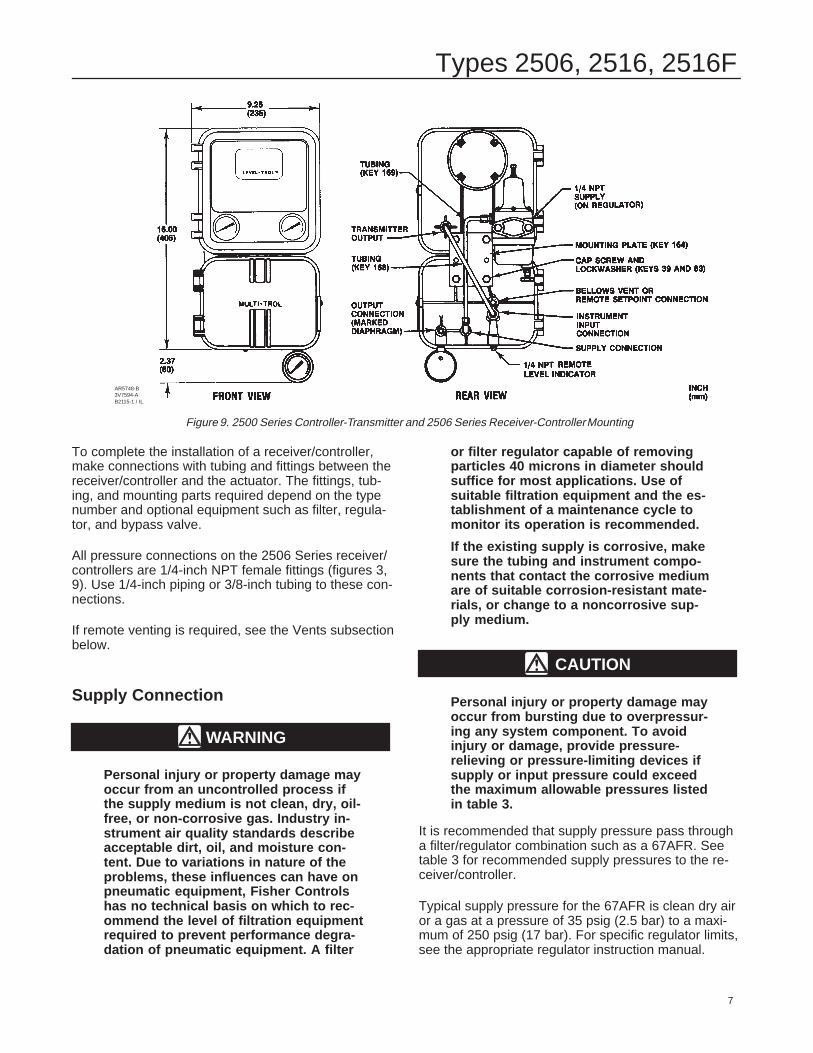
2500 Series Controller/Transmitter and2506 Series Receiver/ControllerMountingIf the controller/transmitter and receiver/controller areordered simultaneously, the factory will mount themtogether before shipment (figure 9). For examples of
Figure 8. Pipestand MountingAD4913-HA3845-1 / IL
typical transmitter/receiver mounting arrangements,see figures 10 and 11.
If the receiver/controller is ordered separately for usewith a 2500 Series controller/transmitter, it may nothave the required mounting parts. If mounting partsare required, consult the parts list under the specificmounting application.
See figure 9 for key number locations.
1. Install lock washers (key 83) on the cap screws(key 39). Then, insert the cap screws through themounting plate from ‘‘back to front’’. Thread the capscrews into the mounting holes in the receiver/control-ler case and tighten.
2. Install lock washers (key 83) on the cap screws(key 48). Then, insert the cap screws through themounting plate from ‘‘back to front’’. Thread the capscrews into the mounting holes in the controller/trans-mitter.
3. If supply pressure is piped through a filter/regulator,bolt the regulator to the back of the controller/transmit-ter.
4. Provide appropriate piping connections betweenthe units as shown in figures 10 or 11.
Connections
WARNING
The controller is capable of providingfull supply pressure to connected equip-ment. To avoid personal injury andequipment damage, make sure the sup-ply pressure never exceeds the maxi-mum safe working pressure of any con-nected equipment.
Types 2506, 2516, 2516F
7
Figure 9. 2500 Series Controller-Transmitter and 2506 Series Receiver-Controller Mounting
AR5748-B3V7594-AB2115-1 / IL
To complete the installation of a receiver/controller,make connections with tubing and fittings between thereceiver/controller and the actuator. The fittings, tub-ing, and mounting parts required depend on the typenumber and optional equipment such as filter, regula-tor, and bypass valve.
All pressure connections on the 2506 Series receiver/controllers are 1/4-inch NPT female fittings (figures 3,9). Use 1/4-inch piping or 3/8-inch tubing to these con-nections.
If remote venting is required, see the Vents subsectionbelow.
Supply Connection
WARNING
Personal injury or property damage mayoccur from an uncontrolled process ifthe supply medium is not clean, dry, oil-free, or non-corrosive gas. Industry in-strument air quality standards describeacceptable dirt, oil, and moisture con-tent. Due to variations in nature of theproblems, these influences can have onpneumatic equipment, Fisher Controlshas no technical basis on which to rec-ommend the level of filtration equipmentrequired to prevent performance degra-dation of pneumatic equipment. A filter
or filter regulator capable of removingparticles 40 microns in diameter shouldsuffice for most applications. Use ofsuitable filtration equipment and the es-tablishment of a maintenance cycle tomonitor its operation is recommended.
If the existing supply is corrosive, makesure the tubing and instrument compo-nents that contact the corrosive mediumare of suitable corrosion-resistant mate-rials, or change to a noncorrosive sup-ply medium.
CAUTION
Personal injury or property damage mayoccur from bursting due to overpressur-ing any system component. To avoidinjury or damage, provide pressure-relieving or pressure-limiting devices ifsupply or input pressure could exceedthe maximum allowable pressures listedin table 3.
It is recommended that supply pressure pass througha filter/regulator combination such as a 67AFR. Seetable 3 for recommended supply pressures to the re-ceiver/controller.
Typical supply pressure for the 67AFR is clean dry airor a gas at a pressure of 35 psig (2.5 bar) to a maxi-mum of 250 psig (17 bar). For specific regulator limits,see the appropriate regulator instruction manual.
Types 2506, 2516, 2516F
8
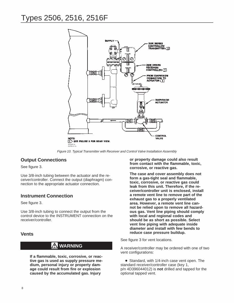
Figure 10. Typical Transmitter with Receiver and Control Valve Installation Assembly
DF5357-AA3701-2 / IL
Output ConnectionsSee figure 3.
Use 3/8-inch tubing between the actuator and the re-ceiver/controller. Connect the output (diaphragm) con-nection to the appropriate actuator connection.
Instrument ConnectionSee figure 3.
Use 3/8-inch tubing to connect the output from thecontrol device to the INSTRUMENT connection on thereceiver/controller.
Vents
WARNING
If a flammable, toxic, corrosive, or reac-tive gas is used as supply pressure me-dium, personal injury or property dam-age could result from fire or explosioncaused by the accumulated gas. Injury
or property damage could also resultfrom contact with the flammable, toxic,corrosive, or reactive gas.
The case and cover assembly does notform a gas-tight seal and flammable,toxic, corrosive, or reactive gas couldleak from this unit. Therefore, if the re-ceiver/controller unit is enclosed, installa remote vent line to remove part of theexhaust gas to a properly ventilatedarea. However, a remote vent line can-not be relied upon to remove all hazard-ous gas. Vent line piping should complywith local and regional codes andshould be as short as possible. Selectvent line piping with adequate insidediameter and install with few bends toreduce case pressure buildup.
See figure 3 for vent locations.
A receiver/controller may be ordered with one of twovent configurations:
� Standard, with 1/4-inch case vent open. Thestandard receiver/controller case (key 1, p/n 4D396044012) is not drilled and tapped for theoptional tapped vent.
Types 2506, 2516, 2516F
9
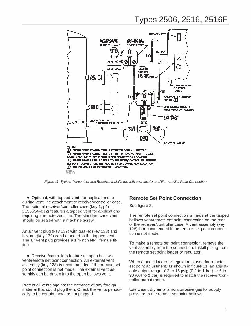
Figure 11. Typical Transmitter and Receiver Installation with an Indicator and Remote Set Point Connection
DF5379-AA3702-2 / IL
� Optional, with tapped vent, for applications re-quiring vent line attachment to receiver/controller case.The optional receiver/controller case (key 1, p/n2E355544012) features a tapped vent for applicationsrequiring a remote vent line. The standard case ventshould be sealed with a machine screw.
An air vent plug (key 137) with gasket (key 138) andhex nut (key 139) can be added to the tapped vent.The air vent plug provides a 1/4-inch NPT female fit-ting.
� Receiver/controllers feature an open bellowsvent/remote set point connection. An external ventassembly (key 128) is recommended if the remote setpoint connection is not made. The external vent as-sembly can be driven into the open bellows vent.
Protect all vents against the entrance of any foreignmaterial that could plug them. Check the vents periodi-cally to be certain they are not plugged.
Remote Set Point ConnectionSee figure 3.
The remote set point connection is made at the tappedbellows vent/remote set point connection on the rearof the receiver/controller case. A vent assembly (key128) is recommended if the remote set point connec-tion is not made.
To make a remote set point connection, remove thevent assembly from the connection. Install piping fromthe remote set point loader or regulator.
When a panel loader or regulator is used for remoteset point adjustment, as shown in figure 11, an adjust-able output range of 3 to 15 psig (0.2 to 1 bar) or 6 to30 (0.4 to 2 bar) is required to match the receiver/con-troller output range.
Use clean, dry air or a noncorrosive gas for supplypressure to the remote set point bellows.
Types 2506, 2516, 2516F
10
StartupIt is important that the output range of the transmitteror other device used as the input to the receiver/con-troller be adjusted so that its output range correspondsto the input signal range of the receiver/controller. Besure the receiver/controller action (direct or reverse) iscorrect for the application.
To start the system:
� For all receiver/controllers, perform steps 1and 2.
1. See table 3 for specific pressure limits. Be sure thecorrect supply pressure is available. If necessary, ad-just the regulator to 20 psig (1.4 bar) for a 3 to 15 psig(0.2 to 1 bar) or 35 psig (2.4 bar) for a 6 to 30 psig(0.4 to 2 bar) receiver/controller range.
2. Turn on the supply pressure to the receiver/control-ler.
� To make the proper level or output pressuresetting for a Type 2506 receiver/controller, go tostep 3. To make the proper level or output pres-sure setting for a Type 2516 receiver/controller, goto step 9. For the Type 2506 receiver/controller:
3. Set the proportional band adjustment at 15 percent(1.5 on the adjustment dial). At this setting, a 1.8 psig(0.1 bar) input pressure causes a 12 psig output pres-sure change. Operate the receiver/controller with theproportional band setting as small as possible.
4. Provide an input pressure equal to the output pres-sure of the transmitter at a value desired or halfwaybetween the transmitter output range. For example, ona receiver/controller, if the desired control point is half-way between the ends of the displacer, provide an in-put of 9 psig (0.6 bar) which is halfway between 3 and15 psig (0.2 and 1 bar) transmitter output range.
5. Set the output pressure adjustment to give a con-troller output that is halfway between its output range.
6. Vary the input pressure to be sure the full controlleroutput pressure range is produced within the specifiedinput pressure range.
7. Lock the output pressure adjustment and connectthe receiver/controller to the final control element.
8. If the proportional band setting is too narrow, caus-ing instability, widen the proportional band just enoughto stabilize control. After making this adjustment, itmay be necessary to reset the output pressure slightlyto produce the proper control range.
� For the Type 2516 receiver/controller:
9. Set the proportional band adjustment dial at 0 per-cent (minimum proportional band).
10. Set the reset adjustment to the fastest speed(0.005 minutes-per-repeat).
11. Provide an input pressure equal to the outputpressure of the transmitter at a value desired or half-way between the transmitter output range. For exam-ple, on a receiver/controller, if the desired control pointis halfway between the ends of the displacer, providean input of 9 psig (0.6 bar) which is halfway between 3and 15 psig (0.2 and 1 bar) transmitter output range.
12. Adjust the output pressure dial to give a controlleroutput somewhere within the output range of the re-ceiver/controller.
13. Lock the output pressure dial and connect to thefinal control element.
14. If the proportional band is too narrow causing in-stability, widen the proportional band or slow the resetjust enough to stabilize control.
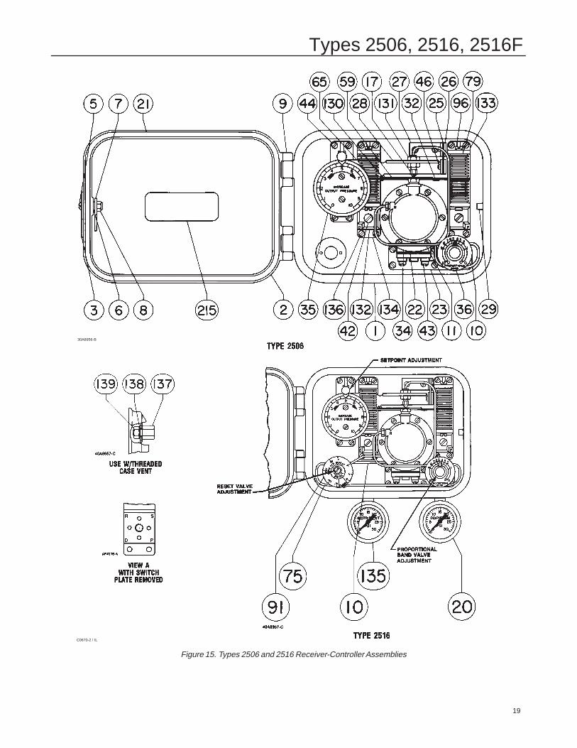
AdjustmentsTo adjust the receiver/controller, open the cover andlocate the appropriate adjustment. See figures 15, 18,19 for the location of adjustments.
Set Point AdjustmentTo adjust the level set point, loosen the knurled knoband rotate the knob around the INCREASE OUTPUTPRESSURE or RAISE LEVEL dial. To raise fluid orinterface level or increase density, rotate the knob inthe direction of the arrow.
To lower level or decrease density, rotate the knob inthe opposite direction. The INCREASE OUTPUTPRESSURE or RAISE LEVEL dial is graduated (inpercent) to show approximate indications of the receiv-er/controller set point. When making adjustments, donot rely only on the dial setting. Monitor the processfluid level to be sure the receiver/controller attains thedesired set point.
For differential gap receiver/controllers, the level set-ting adjustment determines the location of the gapwithin the range of the sensing element.
Remote Set Point AdjustmentOn a receiver/controller with remote set point adjust-ment capability, adjust the set point by changing thepressure to the remote set point connection. Increasethe remote set point signal pressure to decrease thereceiver/controller set point (for a direct acting receiv-er/controller) or increase the receiver/controller setpoint (for a reverse acting receiver/controller).
Types 2506, 2516, 2516F
11
Proportional Band AdjustmentFor proportional and proportional-plus-reset receiver/controllers, the proportional band adjustment deter-mines the amount of change in the input pressure re-quired to change the controller output signal from onelimit of the output signal range to the other limit (with-out the effect of reset action).
Proportional band is expressed as a percent of thesensing element range. That is, with a proportionalband of 100 percent, an input pressure change equalto the sensing element span would change the control-ler output from one limit to the other. With a propor-tional band of 50 percent, an input pressure changeequal to one half the sensing element range wouldchange the controller output from one limit to the oth-er.
The proportional valve dial is graduated from 0 to 10.A setting of 10 on the dial represents a proportionalband of 100 percent; 5 represents a proportional bandof 50 percent.
The receiver/controller is designed for a maximum pro-portional band of 200 percent. The effective band isdetermined by the location of the adjustable nozzleassembly (key 17, figure 15) in the slot in the level setarm (key 28). Most applications require a maximumband of 100 percent so, at the factory, a receiver/con-troller unit is set to the 100 percent value. This settingplaces the nozzle at a point that is halfway betweenthe bellows assemblies. To adjust the proportionalband, rotate the adjustment counterclockwise tobroaden the setting. Rotate the adjustment clockwiseto narrow the setting.
In some applications, a 200 percent proportional bandrange may be required. To obtain the 200 percentrange, move the nozzle assembly to the extreme rightend of the slot in the level set arm.
For differential gap receiver/controllers, the proportion-al band adjustment determines the width of the differ-ential gap. This is the difference between the inputpressures at which the controller output switches fromzero to full supply pressure and back to zero.
Reset Adjustment (Type 2516 Receiver/Controller Only)On proportional-plus-reset receiver/controllers, thereset adjustment determines the time in minutes re-quired for the reset action to produce a change in out-put pressure equal to the change that has occurreddue to proportional band action.
To adjust the reset action, rotate the adjustment clock-wise to decrease, or counterclockwise to increase theminutes per repeat. Increasing the minutes per repeatprovides a slower reset action.
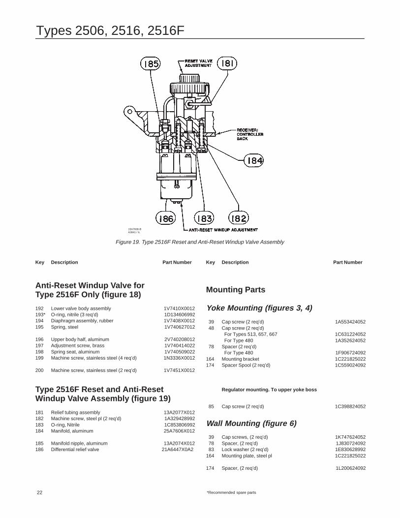
The anti-reset windup valve provides differential pres-sure relief. Its adjustment control extends from theback of the receiver/controller case (figure 19).
The factory sets this valve to relieve when the differen-tial pressure between the proportional and reset bel-lows reaches 5 psi. To set the valve to relieve whenthe differential pressure is as low as 2 psig, turn theadjustment screw clockwise. To set the valve to re-lieve when the differential pressure is as high as 7psig, turn the adjustment screw counterclockwise. Theminimum differential setting yields the minimum differ-ential set point overshoot during startup.
Depending on the characteristics of the process, theanti-reset windup valve can be positioned so that thearrow on the case points to the letters RE or, to theletter P on the back of the manifold. If the arrow pointsto P, the valve opens when receiver/controller outputpressure rises. If the arrow points to RE, the valveopens when receiver/controller output pressure falls.
Calibration
WARNING
The following calibration proceduresrequire taking the controller out of ser-vice. To avoid personal injury and prop-erty damage caused by an uncontrolledprocess, provide some temporarymeans of control for the process beforetaking the receiver/controller out of ser-vice.
See figure 15 for key number and adjustment loca-tions.
When performing the following calibration procedures,open loop conditions must exist and make provisionsto monitor the output pressure. One way to obtain anopen loop is to disconnect the controller output signalline and install a pressure gauge.
Types 2506, 2516, 2516F
12
Note
When calibrating a combined controllerarrangement such as the Type 2500 withthe Type 2506 or 2516 (figure 9), cali-brate the Type 2500 controller/transmit-ter first.
For a direct action receiver/controller:
1. Adjust the INCREASE OUTPUT PRESSURE ad-justment to mid-range on the scale.
2. Turn the proportional band adjustment to 100 per-cent of the scale range.
3. For Type 2516 only, turn the reset valve adjust-ment fully clockwise.
4. Adjust the input pressure to 9 psig (0.6 bar) for a 3to 15 psig (0.2 to 1 bar) or 18 psig (1.2 bar) for a 6 to30 psig (0.4 to 2 bar) receiver/controller.
5. For Type 2516 only, turn the reset valve adjust-ment fully counterclockwise (to the CLOSED position).This locks 9 psig (0.6 bar) or 18 psig (1.2 bar) in thereset bellows.
6. If the output pressure is 9 psig (0.6 bar) for a 3 to15 psig (0.2 to 1 bar) or 18 psig (1.2 bar) for a 6 to 30psig (0.4 to 2 bar) receiver/controller, go to step 8. Ifnot, continue with step 7.
7. If the output pressure span is too low, move thenozzle down towards the flapper, if output pressure istoo high, move the nozzle up. Continue by trial anderror until the desired setting is obtained.
8. Adjust the input pressure to 15 psig (1 bar) for a 3to 15 psig (0.2 to 1 bar) or 30 psig (2 bar) for a 6 to 30psig (0.4 to 2 bar) receiver/controller.
9. The output pressure should be 15 psig (1 bar) for a3 to 15 psig (0.2 to 1 bar) or 30 psig (2 bar) for a 6 to30 psig (0.4 to 2 bar) receiver/controller. If output pres-sure is within application tolerance, proceed to step12. If not, continue with step 10.
10. If the output pressure span is narrow, move thenozzle slightly to the left or, if the output pressure spanis too wide, move it to the right and repeat steps 4 and6 through 10.
11. Repeat the steps until the receiver/controller iswithin application requirements.
12. Reconnect the receiver/controller to the controlloop and see the Adjustment section.
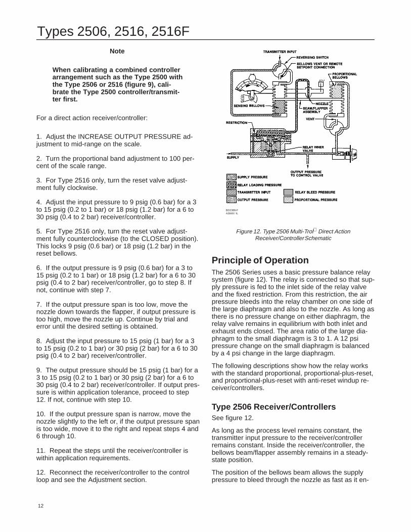
Figure 12. Type 2506 Multi-Trol Direct ActionReceiver/Controller Schematic
BD2388-FA3849 / IL
Principle of OperationThe 2506 Series uses a basic pressure balance relaysystem (figure 12). The relay is connected so that sup-ply pressure is fed to the inlet side of the relay valveand the fixed restriction. From this restriction, the airpressure bleeds into the relay chamber on one side ofthe large diaphragm and also to the nozzle. As long asthere is no pressure change on either diaphragm, therelay valve remains in equilibrium with both inlet andexhaust ends closed. The area ratio of the large dia-phragm to the small diaphragm is 3 to 1. A 12 psipressure change on the small diaphragm is balancedby a 4 psi change in the large diaphragm.
The following descriptions show how the relay workswith the standard proportional, proportional-plus-reset,and proportional-plus-reset with anti-reset windup re-ceiver/controllers.
Type 2506 Receiver/ControllersSee figure 12.
As long as the process level remains constant, thetransmitter input pressure to the receiver/controllerremains constant. Inside the receiver/controller, thebellows beam/flapper assembly remains in a steady-state position.
The position of the bellows beam allows the supplypressure to bleed through the nozzle as fast as it en-
Types 2506, 2516, 2516F
13
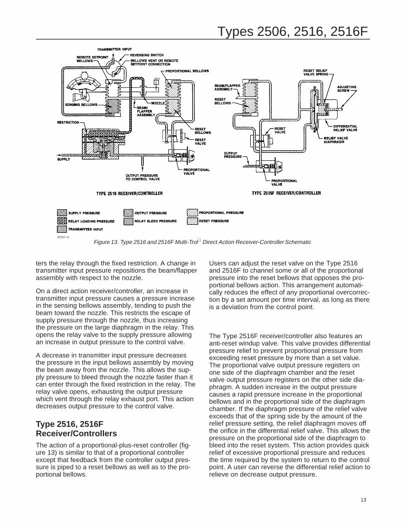
Figure 13. Type 2516 and 2516F Multi-Trol Direct Action Receiver-Controller SchematicB2116 / IL
ters the relay through the fixed restriction. A change intransmitter input pressure repositions the beam/flapperassembly with respect to the nozzle.
On a direct action receiver/controller, an increase intransmitter input pressure causes a pressure increasein the sensing bellows assembly, tending to push thebeam toward the nozzle. This restricts the escape ofsupply pressure through the nozzle, thus increasingthe pressure on the large diaphragm in the relay. Thisopens the relay valve to the supply pressure allowingan increase in output pressure to the control valve.
A decrease in transmitter input pressure decreasesthe pressure in the input bellows assembly by movingthe beam away from the nozzle. This allows the sup-ply pressure to bleed through the nozzle faster than itcan enter through the fixed restriction in the relay. Therelay valve opens, exhausting the output pressurewhich vent through the relay exhaust port. This actiondecreases output pressure to the control valve.
Type 2516, 2516F Receiver/ControllersThe action of a proportional-plus-reset controller (fig-ure 13) is similar to that of a proportional controllerexcept that feedback from the controller output pres-sure is piped to a reset bellows as well as to the pro-portional bellows.
Users can adjust the reset valve on the Type 2516and 2516F to channel some or all of the proportionalpressure into the reset bellows that opposes the pro-portional bellows action. This arrangement automati-cally reduces the effect of any proportional overcorrec-tion by a set amount per time interval, as long as thereis a deviation from the control point.
The Type 2516F receiver/controller also features ananti-reset windup valve. This valve provides differentialpressure relief to prevent proportional pressure fromexceeding reset pressure by more than a set value.The proportional valve output pressure registers onone side of the diaphragm chamber and the resetvalve output pressure registers on the other side dia-phragm. A sudden increase in the output pressurecauses a rapid pressure increase in the proportionalbellows and in the proportional side of the diaphragmchamber. If the diaphragm pressure of the relief valveexceeds that of the spring side by the amount of therelief pressure setting, the relief diaphragm moves offthe orifice in the differential relief valve. This allows thepressure on the proportional side of the diaphragm tobleed into the reset system. This action provides quickrelief of excessive proportional pressure and reducesthe time required by the system to return to the controlpoint. A user can reverse the differential relief action torelieve on decrease output pressure.
Types 2506, 2516, 2516F
14
Maintenance
Receiver/controller parts are subject to normal wearand may require inspection or replacement. The fre-quency of inspection and parts replacement dependsupon the severity of the service conditions. When in-spection or repairs are needed, disassemble onlythose parts necessary to accomplish the job.
Select the appropriate maintenance procedures andperform the appropriate steps. Each procedure re-quires that supply pressure and process pressure beshut off before beginning maintenance.
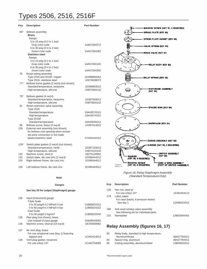
Establish a maintenance cycle to regularly clean thevents (figure 3). Also, establish a maintenance cycle toclear the relay orifice (key 88, figure 16) by pushing inthe plunger of the core assembly (key 89).
Due to the care Fisher Controls takes in meeting allmanufacturing requirements (For example: heat treat-ing, dimensional tolerances, and other manufacturingspecifications), use only genuine replacement partsmanufactured or furnished by Fisher Controls.
WARNING
The following maintenance proceduresrequire taking the controller out of ser-vice. To avoid personal injury and prop-erty damage caused by an uncontrolledprocess, provide some temporarymeans of controlling the process beforetaking the receiver/controller out of ser-vice. Release any trapped pressure fromthe controller and vent supply pressurebefore disassembly.
Changing Controller Action
See figure 15 for key number locations, unless other-wise directed.
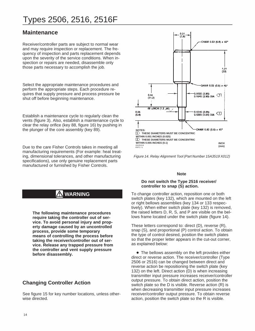
Figure 14. Relay Alignment Tool (Part Number 15A3519 X012)
15A3519-BA5871 / IL
INCH(mm)
NOTES:THESE DIAMETERS MUST BE CONCENTRIC
WITHIN 0.001 INCHES (0.025)THESE DIAMETERS MUST BE CONCENTRIC
WITHIN 0.005 INCHES (0.1)2
1
Note
Do not switch the Type 2516 receiver/controller to snap (S) action.
To change controller action, reposition one or bothswitch plates (key 132), which are mounted on the leftor right bellows assemblies (key 134 or 133 respec-tively). When either switch plate (key 132) is removed,the raised letters D, R, S, and P are visible on the bel-lows frame located under the switch plate (figure 14).
These letters correspond to: direct (D), reverse (R),snap (S), and proportional (P) control action. To obtainthe type of control desired, position the switch platesso that the proper letter appears in the cut-out corner,as explained below:
� The bellows assembly on the left provides eitherdirect or reverse action. The receiver/controller (Type2506 or 2516) can be changed between direct andreverse action be repositioning the switch plate (key132) on the left. Direct action (D) is when increasingtransmitter input pressure increases receiver/controlleroutput pressure. To obtain direct action, position theswitch plate so the D is visible. Reverse action (R) iswhen decreasing transmitter input pressure increasesreceiver/controller output pressure. To obtain reverseaction, position the switch plate so the R is visible.
Types 2506, 2516, 2516F
15
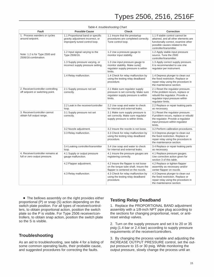
Table 4. troubleshooting ChartFault Possible Cause Check Correction
1. Process wanders or cyclesaround setpoint.
1.1 Proportional band or specificgravity adjustment incorrect, orimproperly tuned control loop.
1.1 Insure that the prestartupprocedures are completed correctly.Tune control loop.
1.1 If stable control cannot beattained, and all other elements arefunctionally correct, examine otherpossible causes related to thecontroller/transmitter.
Note: 1.2 is for Type 2500 and2506/16 combination.
1.2 Input signal varying to the Type 2506/16.
1.2 Use a pressure gauge tomonitor input stability.
1.2 Apply stable input pressuresource. Tune the 2500controller/transmitter.
1.3 Use input pressure gauge tomonitor stability. Make sureregulator supply pressure is withinlimits.
1.3 Apply correct supply pressure.It is recommended to use oneregulator per instrument.
1.4 Relay malfunction. 1.4 Check for relay malfunction byusing the testing relay deadbandprocedure.
1.4 Depress plunger to clean outthe fixed restriction. Replace orrepair relay using the procedure inthe maintenance section.
2. Receiver/controller controllingoff setpoint or switching point.
2.1 Supply pressure not setcorrectly.
2.1 Make sure regulator supplypressure is set correctly. Make sureregulator supply pressure is withinlimits.
2.1 Reset the regulator pressure. If the problem recurs, replace orrebuild the regulator. Provide aregulator input pressure withinregulator limits.
2.2 Leak in the receiver/controllerloop.
2.2 Use soap and water to checkfor internal and external leaks.
2.2 Replace or repair leaking partsas necessary.
3. Receiver/controller cannotobtain full output range.
3.1 Supply pressure not setcorrectly.
3.1 Make sure supply pressure isset correctly. Make sure regulatorsupply pressure is within limits.
3.1 Reset the regulator pressure. If problem recurs, replace or rebuildthe regulator. Provide a regulatorinput pressure within regulatorlimits.
3.2 Nozzle adjustment. 3.2 Insure the nozzle is not loose. 3.2 Perform calibration procedures.
3.3 Relay malfunction. 3.3 Check for relay malfunction byusing the testing relay deadbandprocedure.
3.3 Depress plunger to clean outthe fixed restriction. Replace orrepair relay using the procedure inthe maintenance section.
3.4 Leaking controller/transmitterloop.
3.4 Use soap and water to checkfor internal and external leaks.
3.4 Replace or repair leaking partsas necessary.
4. Receiver/controller remains atfull or zero output pressure.
4.1 Supply or output pressuregauge malfunction.
4.1 Insure the pressure gauges areregistering correctly.
4.1 Replace pressure gauges. Use corrective action given forsection 3 of this table.
4.2 Flapper adjustment. 4.2 Insure the flapper is not looseon the torque tube shaft. Insure theflapper is centered on the nozzle.
4.2 Replace or tighten flapperassembly as necessary and/orcenter flapper on nozzle.
4.3 Relay malfunction. 4.3 Check for relay malfunction byusing the testing relay deadbandprocedure.
4.3 Depress plunger to clean outthe fixed restriction. Replace orrepair relay using the procedure inthe maintenance section.
� The bellows assembly on the right provides eitherproportional (P) or snap (S) action depending on theswitch plate position. For all types of receiver/control-lers, to obtain proportional action, position the switchplate so the P is visible. For Type 2506 receiver/con-trollers, to obtain snap action, position the switch plateso the S is visible.
TroubleshootingAs an aid to troubleshooting, see table 4 for a listing ofsome common operating faults, their probable cause,and suggested procedures for correcting the faults.
Testing Relay Deadband1. Replace the PROPORTIONAL BAND adjustmentassembly with a 1/8-inch NPT pipe plug according tothe sections for changing proportional, reset, or anti-reset windup valves.
2. Turn on the supply pressure and set it to 20 or 35psig (1.4 bar or 2.4 bar) according to supply pressurerequirements of the receiver/controllers.
3. By changing the process variable and adjusting theINCREASE OUTPUT PRESSURE control, set the out-put pressure to 15 or 30 psig. While monitoring theoutput pressure, slowly change the process until an
Types 2506, 2516, 2516F
16
output pressure change just begins. Record the valueof the process variable at this detection point.
4. Change the process variable in the opposite direc-tion until another output pressure change just begins.Again, record the value of the process variable. If thedifference between the two values (the deadband) ismore than 0.2 percent of the maximum displacerlength, the relay must be repaired or replaced.
5. See the relay removal and replacement proceduresand, if necessary, the relay disassembly and assemblyprocedures if the relay is to be repaired.
6. Turn off the supply pressure, remove the pipe plug,and install the PROPORTIONAL BAND adjustmentassembly.
Replacing Receiver/Controller Parts
See figure 15 for key number locations, unless other-wise indicated.
Bellows Replacement
Use the following bellows replacement procedure toreplace defective bellows or change the output signalrange.
2. Take out the four bellows screws (key 96). Theseare special screws with air passages in them so, becareful not to lose them.
3. Compress the bellows (both are key 65) slightlyand slip them out of the bellows frame (keys 133 or134).
4. Unscrew the bellows from the beam (key 59). Agasket (key 79) fits between the end of the bellowsand the bellows frame.
5. Inspect each bellows and gasket and, if necessary,replace them.
Replacement
1. First install the bellows gasket (key 79), then installeach bellows (key 59) by screwing it onto the beam(key 59).
2. Compress the bellows slightly and slip them intothe bellows frame (key 133 or 134).
3. Secure the screws (key 96) and replace the tubing.
4. Check all tubing connections and the bellowsscrews for leaks. Tighten as necessary and proceed tothe Calibration section.
5. If a bellows assembly (key 65) with a differentrange is installed, replace the gauges (key 20 or 135)with those with an appropriate measurement capabili-ty.
Changing the RelayRemove the relay to clean, repair, or replace it.
Removal
1. Disconnect the tubing (key 11) from the relay.
2. Remove two relay mounting screws, the relay, andthe relay gasket (keys 43, 34, and 22).
Replacement
1. Install a new gasket (key 22), the replacementrelay (key 34), and secure with two mounting screws(key 43).
2. Connect the tubing (key 11) to the relay.
3. See the testing relay deadband procedures in thissection.
4. If the deadband is within tolerance, see the Calibra-tion section.
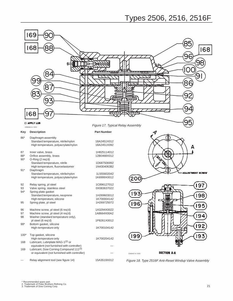
Relay Assembly Maintenance
The alignment tool shown in figure 14 may not be re-quired for assembly of the relay, but it does preventexcessive air consumption and deadband. If low airconsumption and minimum deadband are required,make or purchase the alignment tool before disassem-bling the relay.
See figures 16, 17 for key number locations, unlessotherwise indicated.
Disassembly
1. Remove the relay according to the changing relayprocedures in this section.
2. Remove the orifice assembly (key 88) and check tosee if the orifice is plugged or damaged. Also, inspectthe O-ring (key 90).
3. Remove six casing screws and washers (keys 96and 98) and, remove the diaphragm (key 91). For ahigh temperature relay, also remove the gasket (key100) that covers the diaphragm.
Types 2506, 2516, 2516F
17
4. Remove the spacer ring (key 84), diaphragm as-sembly (key 86), and relay spring (key 92) from therelay body (key 83). On a high temperature relay, alsoremove the gasket (key 99) from underneath the dia-phragm assembly.
5. Remove the four screws (key 97), spring plate (key95), spring plate gasket (key 94), spring (key 93), andinner valve (key 87).
6. Inspect the valve seats for roughness due to corro-sion. One seat is in the diaphragm assembly and theother is in the relay body (key 83). If necessary, re-place the parts.
7. Inspect the diaphragms and gaskets, and replacethem if necessary. Also, replace the spring and innervalve (keys 92 and 87) if they show signs of corrosion.The lower diaphragm comes as part of an assemblyand must be installed as an assembly.
8. Clean all parts thoroughly before assembly.
Assembly
1. Place the relay spring in the relay body. For a hightemperature relay, also install a bottom gasket. Installthe diaphragm assembly, spacer ring, and top dia-phragm on the body so that all flow passage holes arelined up. For a high temperature relay, also install agasket over the top diaphragm.
2. Place the casing assembly on the top diaphragmso that the lugs on the casing and spacer ring line upand are also lined up with the body lug.
3. Lubricate the machine screws (key 96) with Lubri-plate MAG-1(1) or equivalent. Install the machinescrews and, for standard relays, the washers (key 98),but do not tighten the screws.
4. If the optional alignment tool (figure 14) is available,insert the small end of the tool into the opening in therelay body. If the tool does not engage in the hole ofthe diaphragm assembly, move the parts slightly toreposition the diaphragm until the alignment tool doesengage the hole in the diaphragm assembly. Do notremove the alignment tool until the machine screws(key 96) have been tightened.
5. Tighten the machine screws (key 96) evenly. Re-move the alignment tool (if one is used).
6. Install the inner valve, spring, gasket, and coverplate (keys 87, 93, 94, and 95). Secure with the fourmachine screws (key 97).
7. Lubricate the O-rings (key 90) with Dow CorningCompound 111(2) or equivalent and the orifice assem-bly (key 88) with Lubriplate MAG-1 or equivalent.Install the O-rings on the orifice assembly and installthe orifice assembly into the casing assembly.
8. Install the relay according to the changing relayprocedures.
Changing Proportional or Reset Valve1. Disconnect the appropriate tubing(s) from the pro-portional or reset valve.
2. Removing the valve assembly:
a. Remove the proportional valve assembly by un-screwing it from the relay base. Install the replace-ment assembly.
b. Remove the reset valve assembly by unscrew-ing the two machine screws (key 182, not shown)located behind the reset valve on the back of thecase. Install the replacement assembly.
Parts OrderingWhen replacement parts are required, always usegenuine Fisher parts.
Whenever corresponding with the Fisher Controlssales office or representative, include the receiver/con-troller type number and the serial number. The serialnumber can be found on the nameplate. When order-ing replacement parts, also state the complete11-character part number of each part required asfound in the following parts list.
Parts KitsKey Description Part Number
Receiver/Controller Repair KitsContains keys 17, 19, 21, 24, 38, and 45Standard Temperature R2506X0L12High Temperature R2506X0H12
Relay Repair KitsContains keys 22, 85, 86, 87, 88, 90, 91,92, 93, 94 (99 and 100 high temperature only)Standard Temperature RRELAYX0L12High Temperature RRELAYX0H12
Relay Replacement KitContains key 22 (43 for Type 2500 and 2502)and the relay assemblyStandard Temperature RRELAYX0L22High Temperature RRELAYX0H22
1. Trademark of Fiske Brothers Refining Co.2. Trademark of Dow Corning Corp.
Types 2506, 2516, 2516F
18
Parts List
Receiver/Controller Common Parts (figure 15)
Note
Case Vent Options
� The standard receiver/controller case (key 1, p/n4D396044012) features an open case vent. The case isnot drilled for the optional tapped vent.
� All receiver/controller cases feature an openbellows vent/remote set point connection. A externalvent assembly (key 128) is recommended if the remoteset point connection is not made.
� The optional receiver/controller case (key 1, p/n2E355544012) features a tapped vent for applicationsrequiring a remote vent line. The standard case vent issealed w/a machine screw. An external connection (airvent plug, key 137) w/gasket (key 138) and hex nut (key139) can be added to the tapped vent.
1 Controller case (controller back), die cast zincfor Types 2506, 2516Std: W/open case vent (no optionaltapped vent for vent line) 4D396044012
Optional: W/tapped vent for vent line(case vent sealed with machine screw) 2E355544012
Additional option: Case pressure-testedto 2 psig (0.1 bar). Contact yourFisher Controls sales office orrepresentative to order pressure testing.Label (key 179) is added to the case. 2E355544012
1 Controller case (controller back), die cast zincfor Type 2516F, w/open case vent (no optional
tapped vent for vent line) 15A7611X0122 Controller cover, die cast zinc 4D3961440123 Door handle, steel pl 1C897225082
4 Door handle shaft, stainless steel(not shown) 1C898414012
�Fisher Controls International, Inc. 1978, 1993; All Rights Reserved
Multi-Trol, Level-Trol, Fisher, Fisher-Rosemount, and Managing The Process Better are marks owned by Fisher Controls International, Inc. or Fisher-Rosemount Systems, Inc.All other marks are the property of their respective owners.