Our lives are filled with light. Through vision, the most valued of our senses, light can evoke spiritual emotions, such as when we view a magnificent sunset or glimpse a rainbow breaking through the clouds. Light can also simply amuse us in a theater, or warn us to stop at an intersection. It has innumerable uses beyond vision. Light can carry telephone signals through glass fibers or cook a meal in a solar oven. Life itself could not exist without light’s energy. From photosynthesis in plants to the sun warming a cold-blooded animal, its supply of energy is vital. Figure 25.2 Double Rainbow over the bay of Pocitos in Montevideo, Uruguay. (credit: Madrax, Wikimedia Commons) We already know that visible light is the type of electromagnetic waves to which our eyes respond. That knowledge still leaves many questions regarding the nature of light and vision. What is color, and how do our eyes detect it? Why do diamonds sparkle? How does light travel? How do lenses and mirrors form images? These are but a few of the questions that are answered by the study of optics. Optics is the branch of physics that deals with the behavior of visible light and other electromagnetic waves. In particular, optics is concerned with the generation and propagation of light and its interaction with matter. What we have already learned about the generation of light in our study of heat transfer by radiation will be expanded upon in later topics, especially those on atomic physics. Now, we will concentrate on the propagation of light and its interaction with matter. It is convenient to divide optics into two major parts based on the size of objects that light encounters. When light interacts with an object that is several times as large as the light’s wavelength, its observable behavior is like that of a ray; it does not prominently display its wave characteristics. We call this part of optics “geometric optics.” This chapter will concentrate on such situations. When light interacts with smaller objects, it has very prominent wave characteristics, such as constructive and destructive interference. Wave Optics will concentrate on such situations. 25.1 The Ray Aspect of Light There are three ways in which light can travel from a source to another location. (See Figure 25.3.) It can come directly from the source through empty space, such as from the Sun to Earth. Or light can travel through various media, such as air and glass, to the person. Light can also arrive after being reflected, such as by a mirror. In all of these cases, light is modeled as traveling in straight lines called rays. Light may change direction when it encounters objects (such as a mirror) or in passing from one material to another (such as in passing from air to glass), but it then continues in a straight line or as a ray. The word ray comes from mathematics and here means a straight line that originates at some point. It is acceptable to visualize light rays as laser rays (or even science fiction depictions of ray guns). Ray The word “ray” comes from mathematics and here means a straight line that originates at some point. 984 Chapter 25 | Geometric Optics This OpenStax book is available for free at http://cnx.org/content/col11406/1.9
Transcript
Our lives are filled with light. Through vision, the most valued of our senses, light can evoke spiritual emotions, such as when weview a magnificent sunset or glimpse a rainbow breaking through the clouds. Light can also simply amuse us in a theater, orwarn us to stop at an intersection. It has innumerable uses beyond vision. Light can carry telephone signals through glass fibersor cook a meal in a solar oven. Life itself could not exist without light’s energy. From photosynthesis in plants to the sun warminga cold-blooded animal, its supply of energy is vital.
Figure 25.2 Double Rainbow over the bay of Pocitos in Montevideo, Uruguay. (credit: Madrax, Wikimedia Commons)
We already know that visible light is the type of electromagnetic waves to which our eyes respond. That knowledge still leavesmany questions regarding the nature of light and vision. What is color, and how do our eyes detect it? Why do diamondssparkle? How does light travel? How do lenses and mirrors form images? These are but a few of the questions that areanswered by the study of optics. Optics is the branch of physics that deals with the behavior of visible light and otherelectromagnetic waves. In particular, optics is concerned with the generation and propagation of light and its interaction withmatter. What we have already learned about the generation of light in our study of heat transfer by radiation will be expandedupon in later topics, especially those on atomic physics. Now, we will concentrate on the propagation of light and its interactionwith matter.
It is convenient to divide optics into two major parts based on the size of objects that light encounters. When light interacts withan object that is several times as large as the light’s wavelength, its observable behavior is like that of a ray; it does notprominently display its wave characteristics. We call this part of optics “geometric optics.” This chapter will concentrate on suchsituations. When light interacts with smaller objects, it has very prominent wave characteristics, such as constructive anddestructive interference. Wave Optics will concentrate on such situations.
25.1 The Ray Aspect of Light
There are three ways in which light can travel from a source to another location. (See Figure 25.3.) It can come directly from thesource through empty space, such as from the Sun to Earth. Or light can travel through various media, such as air and glass, tothe person. Light can also arrive after being reflected, such as by a mirror. In all of these cases, light is modeled as traveling instraight lines called rays. Light may change direction when it encounters objects (such as a mirror) or in passing from onematerial to another (such as in passing from air to glass), but it then continues in a straight line or as a ray. The word ray comesfrom mathematics and here means a straight line that originates at some point. It is acceptable to visualize light rays as laserrays (or even science fiction depictions of ray guns).
Ray
The word “ray” comes from mathematics and here means a straight line that originates at some point.
984 Chapter 25 | Geometric Optics
This OpenStax book is available for free at http://cnx.org/content/col11406/1.9
Figure 25.3 Three methods for light to travel from a source to another location. (a) Light reaches the upper atmosphere of Earth traveling throughempty space directly from the source. (b) Light can reach a person in one of two ways. It can travel through media like air and glass. It can also reflectfrom an object like a mirror. In the situations shown here, light interacts with objects large enough that it travels in straight lines, like a ray.
Experiments, as well as our own experiences, show that when light interacts with objects several times as large as itswavelength, it travels in straight lines and acts like a ray. Its wave characteristics are not pronounced in such situations. Since thewavelength of light is less than a micron (a thousandth of a millimeter), it acts like a ray in the many common situations in whichit encounters objects larger than a micron. For example, when light encounters anything we can observe with unaided eyes, suchas a mirror, it acts like a ray, with only subtle wave characteristics. We will concentrate on the ray characteristics in this chapter.
Since light moves in straight lines, changing directions when it interacts with materials, it is described by geometry and simpletrigonometry. This part of optics, where the ray aspect of light dominates, is therefore called geometric optics. There are twolaws that govern how light changes direction when it interacts with matter. These are the law of reflection, for situations in whichlight bounces off matter, and the law of refraction, for situations in which light passes through matter.
Geometric Optics
The part of optics dealing with the ray aspect of light is called geometric optics.
25.2 The Law of Reflection
Whenever we look into a mirror, or squint at sunlight glinting from a lake, we are seeing a reflection. When you look at this page,too, you are seeing light reflected from it. Large telescopes use reflection to form an image of stars and other astronomicalobjects.
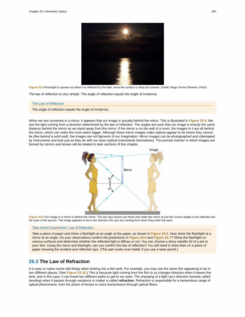
The law of reflection is illustrated in Figure 25.4, which also shows how the angles are measured relative to the perpendicular tothe surface at the point where the light ray strikes. We expect to see reflections from smooth surfaces, but Figure 25.5 illustrateshow a rough surface reflects light. Since the light strikes different parts of the surface at different angles, it is reflected in manydifferent directions, or diffused. Diffused light is what allows us to see a sheet of paper from any angle, as illustrated in Figure25.6. Many objects, such as people, clothing, leaves, and walls, have rough surfaces and can be seen from all sides. A mirror, onthe other hand, has a smooth surface (compared with the wavelength of light) and reflects light at specific angles, as illustrated inFigure 25.7. When the moon reflects from a lake, as shown in Figure 25.8, a combination of these effects takes place.
Chapter 25 | Geometric Optics 985
Figure 25.4 The law of reflection states that the angle of reflection equals the angle of incidence— r = i . The angles are measured relative to the
perpendicular to the surface at the point where the ray strikes the surface.
Figure 25.5 Light is diffused when it reflects from a rough surface. Here many parallel rays are incident, but they are reflected at many different anglessince the surface is rough.
Figure 25.6 When a sheet of paper is illuminated with many parallel incident rays, it can be seen at many different angles, because its surface is roughand diffuses the light.
Figure 25.7 A mirror illuminated by many parallel rays reflects them in only one direction, since its surface is very smooth. Only the observer at aparticular angle will see the reflected light.
986 Chapter 25 | Geometric Optics
This OpenStax book is available for free at http://cnx.org/content/col11406/1.9
Figure 25.8 Moonlight is spread out when it is reflected by the lake, since the surface is shiny but uneven. (credit: Diego Torres Silvestre, Flickr)
The law of reflection is very simple: The angle of reflection equals the angle of incidence.
The Law of Reflection
The angle of reflection equals the angle of incidence.
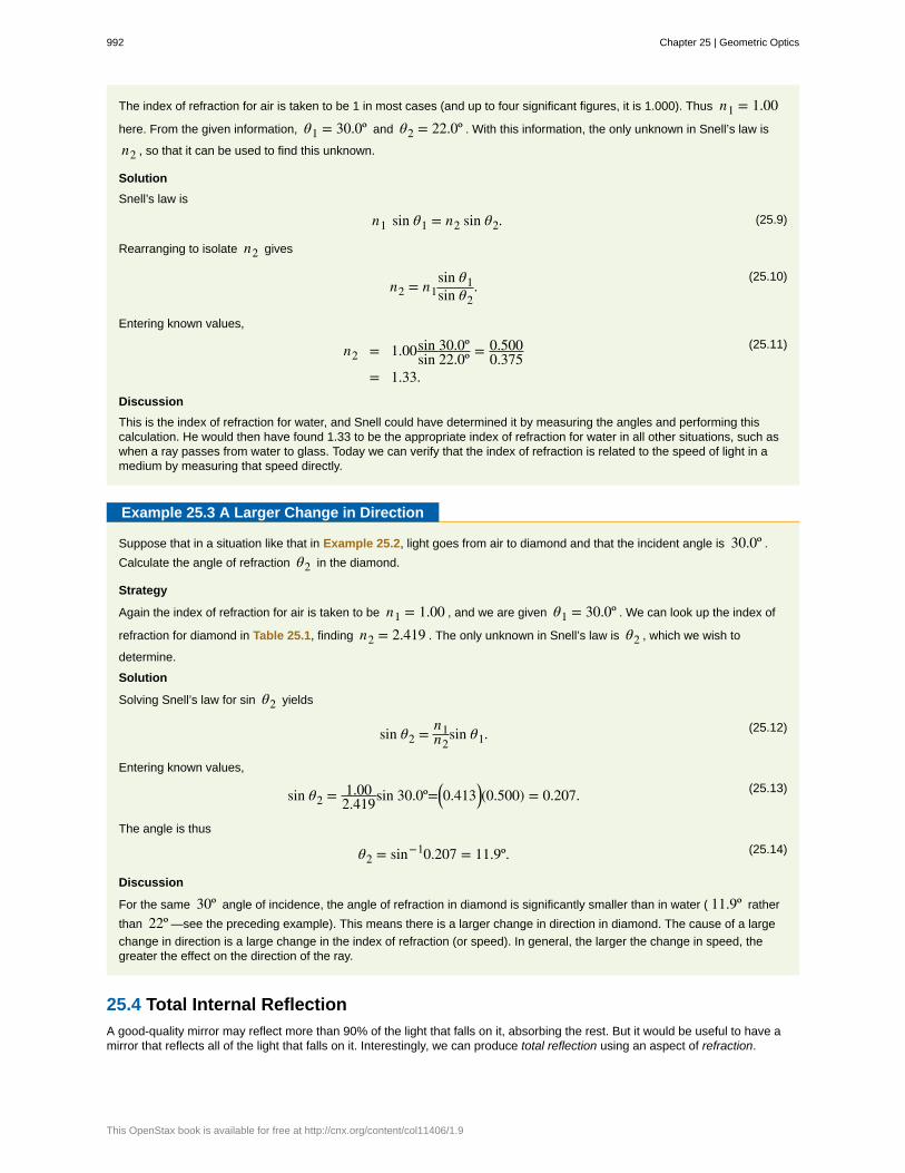
When we see ourselves in a mirror, it appears that our image is actually behind the mirror. This is illustrated in Figure 25.9. Wesee the light coming from a direction determined by the law of reflection. The angles are such that our image is exactly the samedistance behind the mirror as we stand away from the mirror. If the mirror is on the wall of a room, the images in it are all behindthe mirror, which can make the room seem bigger. Although these mirror images make objects appear to be where they cannotbe (like behind a solid wall), the images are not figments of our imagination. Mirror images can be photographed and videotapedby instruments and look just as they do with our eyes (optical instruments themselves). The precise manner in which images areformed by mirrors and lenses will be treated in later sections of this chapter.
Figure 25.9 Our image in a mirror is behind the mirror. The two rays shown are those that strike the mirror at just the correct angles to be reflected intothe eyes of the person. The image appears to be in the direction the rays are coming from when they enter the eyes.
Take-Home Experiment: Law of Reflection
Take a piece of paper and shine a flashlight at an angle at the paper, as shown in Figure 25.6. Now shine the flashlight at amirror at an angle. Do your observations confirm the predictions in Figure 25.6 and Figure 25.7? Shine the flashlight onvarious surfaces and determine whether the reflected light is diffuse or not. You can choose a shiny metallic lid of a pot oryour skin. Using the mirror and flashlight, can you confirm the law of reflection? You will need to draw lines on a piece ofpaper showing the incident and reflected rays. (This part works even better if you use a laser pencil.)
25.3 The Law of Refraction
It is easy to notice some odd things when looking into a fish tank. For example, you may see the same fish appearing to be intwo different places. (See Figure 25.10.) This is because light coming from the fish to us changes direction when it leaves thetank, and in this case, it can travel two different paths to get to our eyes. The changing of a light ray’s direction (loosely calledbending) when it passes through variations in matter is called refraction. Refraction is responsible for a tremendous range ofoptical phenomena, from the action of lenses to voice transmission through optical fibers.
Chapter 25 | Geometric Optics 987
Refraction
The changing of a light ray’s direction (loosely called bending) when it passes through variations in matter is calledrefraction.
Speed of Light
The speed of light not only affects refraction, it is one of the central concepts of Einstein’s theory of relativity. As theaccuracy of the measurements of the speed of light were improved, was found not to depend on the velocity of the sourceor the observer. However, the speed of light does vary in a precise manner with the material it traverses. These facts havefar-reaching implications, as we will see in Special Relativity. It makes connections between space and time and alters ourexpectations that all observers measure the same time for the same event, for example. The speed of light is so importantthat its value in a vacuum is one of the most fundamental constants in nature as well as being one of the four fundamentalSI units.
Figure 25.10 Looking at the fish tank as shown, we can see the same fish in two different locations, because light changes directions when it passesfrom water to air. In this case, the light can reach the observer by two different paths, and so the fish seems to be in two different places. This bendingof light is called refraction and is responsible for many optical phenomena.
Why does light change direction when passing from one material (medium) to another? It is because light changes speed whengoing from one material to another. So before we study the law of refraction, it is useful to discuss the speed of light and how itvaries in different media.
The Speed of LightEarly attempts to measure the speed of light, such as those made by Galileo, determined that light moved extremely fast,perhaps instantaneously. The first real evidence that light traveled at a finite speed came from the Danish astronomer OleRoemer in the late 17th century. Roemer had noted that the average orbital period of one of Jupiter’s moons, as measured fromEarth, varied depending on whether Earth was moving toward or away from Jupiter. He correctly concluded that the apparentchange in period was due to the change in distance between Earth and Jupiter and the time it took light to travel this distance.
From his 1676 data, a value of the speed of light was calculated to be 2.26×10⁸ m/s (only 25% different from today’saccepted value). In more recent times, physicists have measured the speed of light in numerous ways and with increasingaccuracy. One particularly direct method, used in 1887 by the American physicist Albert Michelson (1852–1931), is illustrated inFigure 25.11. Light reflected from a rotating set of mirrors was reflected from a stationary mirror 35 km away and returned to therotating mirrors. The time for the light to travel can be determined by how fast the mirrors must rotate for the light to be returnedto the observer’s eye.
988 Chapter 25 | Geometric Optics
This OpenStax book is available for free at http://cnx.org/content/col11406/1.9
Figure 25.11 A schematic of early apparatus used by Michelson and others to determine the speed of light. As the mirrors rotate, the reflected ray isonly briefly directed at the stationary mirror. The returning ray will be reflected into the observer's eye only if the next mirror has rotated into the correctposition just as the ray returns. By measuring the correct rotation rate, the time for the round trip can be measured and the speed of light calculated.Michelson’s calculated value of the speed of light was only 0.04% different from the value used today.
The speed of light is now known to great precision. In fact, the speed of light in a vacuum is so important that it is accepted asone of the basic physical quantities and has the fixed value
(25.1)= 2.9972458×10⁸ m/s ≈ 3.00×10⁸ m/s,
where the approximate value of 3.00×10⁸ m/s is used whenever three-digit accuracy is sufficient. The speed of light throughmatter is less than it is in a vacuum, because light interacts with atoms in a material. The speed of light depends strongly on thetype of material, since its interaction with different atoms, crystal lattices, and other substructures varies. We define the index ofrefraction of a material to be
(25.2)= ,
where is the observed speed of light in the material. Since the speed of light is always less than in matter and equalsonly in a vacuum, the index of refraction is always greater than or equal to one.
Value of the Speed of Light(25.3)= 2.9972458×10⁸ m/s ≈ 3.00×10⁸ m/s
Index of Refraction(25.4)=
That is, ≥ 1 . Table 25.1 gives the indices of refraction for some representative substances. The values are listed for a
particular wavelength of light, because they vary slightly with wavelength. (This can have important effects, such as colorsproduced by a prism.) Note that for gases, is close to 1.0. This seems reasonable, since atoms in gases are widely separated
and light travels at in the vacuum between atoms. It is common to take = 1 for gases unless great precision is needed.Although the speed of light in a medium varies considerably from its value in a vacuum, it is still a large speed.
Chapter 25 | Geometric Optics 989
Table 25.1 Index of Refraction inVarious Media
Medium n
Gases at 0ºC , 1 atm
Air 1.000293
Carbon dioxide 1.00045
Hydrogen 1.000139
Oxygen 1.000271
Liquids at 20ºC
Benzene 1.501
Carbon disulfide 1.628
Carbon tetrachloride 1.461
Ethanol 1.361
Glycerine 1.473
Water, fresh 1.333
Solids at 20ºC
Diamond 2.419
Fluorite 1.434
Glass, crown 1.52
Glass, flint 1.66
Ice at 20ºC 1.309
Polystyrene 1.49
Plexiglas 1.51
Quartz, crystalline 1.544
Quartz, fused 1.458
Sodium chloride 1.544
Zircon 1.923
Example 25.1 Speed of Light in Matter
Calculate the speed of light in zircon, a material used in jewelry to imitate diamond.
Strategy
The speed of light in a material, , can be calculated from the index of refraction of the material using the equation
= / .
Solution
The equation for index of refraction states that = / . Rearranging this to determine gives
(25.5)= .
The index of refraction for zircon is given as 1.923 in Table 25.1, and is given in the equation for speed of light. Enteringthese values in the last expression gives
(25.6)= 3.00×10⁸ m/s
1.923
= 1.56×10⁸ m/s.
Discussion
This speed is slightly larger than half the speed of light in a vacuum and is still high compared with speeds we normallyexperience. The only substance listed in Table 25.1 that has a greater index of refraction than zircon is diamond. We shallsee later that the large index of refraction for zircon makes it sparkle more than glass, but less than diamond.
990 Chapter 25 | Geometric Optics
This OpenStax book is available for free at http://cnx.org/content/col11406/1.9
Law of RefractionFigure 25.12 shows how a ray of light changes direction when it passes from one medium to another. As before, the angles aremeasured relative to a perpendicular to the surface at the point where the light ray crosses it. (Some of the incident light will bereflected from the surface, but for now we will concentrate on the light that is transmitted.) The change in direction of the light raydepends on how the speed of light changes. The change in the speed of light is related to the indices of refraction of the mediainvolved. In the situations shown in Figure 25.12, medium 2 has a greater index of refraction than medium 1. This means thatthe speed of light is less in medium 2 than in medium 1. Note that as shown in Figure 25.12(a), the direction of the ray movescloser to the perpendicular when it slows down. Conversely, as shown in Figure 25.12(b), the direction of the ray moves awayfrom the perpendicular when it speeds up. The path is exactly reversible. In both cases, you can imagine what happens bythinking about pushing a lawn mower from a footpath onto grass, and vice versa. Going from the footpath to grass, the frontwheels are slowed and pulled to the side as shown. This is the same change in direction as for light when it goes from a fastmedium to a slow one. When going from the grass to the footpath, the front wheels can move faster and the mower changesdirection as shown. This, too, is the same change in direction as for light going from slow to fast.
Figure 25.12 The change in direction of a light ray depends on how the speed of light changes when it crosses from one medium to another. Thespeed of light is greater in medium 1 than in medium 2 in the situations shown here. (a) A ray of light moves closer to the perpendicular when it slowsdown. This is analogous to what happens when a lawn mower goes from a footpath to grass. (b) A ray of light moves away from the perpendicularwhen it speeds up. This is analogous to what happens when a lawn mower goes from grass to footpath. The paths are exactly reversible.
The amount that a light ray changes its direction depends both on the incident angle and the amount that the speed changes.For a ray at a given incident angle, a large change in speed causes a large change in direction, and thus a large change inangle. The exact mathematical relationship is the law of refraction, or “Snell’s Law,” which is stated in equation form as
(25.7)1 sin 1 = 2 sin 2.
Here 1 and 2 are the indices of refraction for medium 1 and 2, and 1 and 2 are the angles between the rays and the
perpendicular in medium 1 and 2, as shown in Figure 25.12. The incoming ray is called the incident ray and the outgoing ray therefracted ray, and the associated angles the incident angle and the refracted angle. The law of refraction is also called Snell’s lawafter the Dutch mathematician Willebrord Snell (1591–1626), who discovered it in 1621. Snell’s experiments showed that the lawof refraction was obeyed and that a characteristic index of refraction could be assigned to a given medium. Snell was notaware that the speed of light varied in different media, but through experiments he was able to determine indices of refractionfrom the way light rays changed direction.
The Law of Refraction(25.8)
1 sin 1 = 2 sin 2
Take-Home Experiment: A Broken Pencil
A classic observation of refraction occurs when a pencil is placed in a glass half filled with water. Do this and observe theshape of the pencil when you look at the pencil sideways, that is, through air, glass, water. Explain your observations. Drawray diagrams for the situation.
Example 25.2 Determine the Index of Refraction from Refraction Data
Find the index of refraction for medium 2 in Figure 25.12(a), assuming medium 1 is air and given the incident angle is30.0º and the angle of refraction is 22.0º .
Strategy
Chapter 25 | Geometric Optics 991
The index of refraction for air is taken to be 1 in most cases (and up to four significant figures, it is 1.000). Thus 1 = 1.00
here. From the given information, 1 = 30.0º and 2 = 22.0º . With this information, the only unknown in Snell’s law is
2 , so that it can be used to find this unknown.
Solution
Snell’s law is
(25.9)1 sin 1 = 2 sin 2.
Rearranging to isolate 2 gives
(25.10)2 = 1
sin 1
sin 2.
Entering known values,
(25.11)2 = 1.00sin 30.0º
sin 22.0º= 0.500
0.375
= 1.33.
Discussion
This is the index of refraction for water, and Snell could have determined it by measuring the angles and performing thiscalculation. He would then have found 1.33 to be the appropriate index of refraction for water in all other situations, such aswhen a ray passes from water to glass. Today we can verify that the index of refraction is related to the speed of light in amedium by measuring that speed directly.
Example 25.3 A Larger Change in Direction
Suppose that in a situation like that in Example 25.2, light goes from air to diamond and that the incident angle is 30.0º .
Calculate the angle of refraction 2 in the diamond.
Strategy
Again the index of refraction for air is taken to be 1 = 1.00 , and we are given 1 = 30.0º . We can look up the index of
refraction for diamond in Table 25.1, finding 2 = 2.419 . The only unknown in Snell’s law is 2 , which we wish to
determine.
Solution
Solving Snell’s law for sin 2 yields
(25.12)sin 2 = 1
2sin 1.
Entering known values,
(25.13)sin 2 = 1.00
2.419sin 30.0º= 0.413 (0.500) = 0.207.
The angle is thus
(25.14)2 = sin−10.207 = 11.9º.
Discussion
For the same 30º angle of incidence, the angle of refraction in diamond is significantly smaller than in water ( 11.9º rather
than 22º —see the preceding example). This means there is a larger change in direction in diamond. The cause of a largechange in direction is a large change in the index of refraction (or speed). In general, the larger the change in speed, thegreater the effect on the direction of the ray.
25.4 Total Internal Reflection
A good-quality mirror may reflect more than 90% of the light that falls on it, absorbing the rest. But it would be useful to have amirror that reflects all of the light that falls on it. Interestingly, we can produce total reflection using an aspect of refraction.
992 Chapter 25 | Geometric Optics
This OpenStax book is available for free at http://cnx.org/content/col11406/1.9
Consider what happens when a ray of light strikes the surface between two materials, such as is shown in Figure 25.13(a). Partof the light crosses the boundary and is refracted; the rest is reflected. If, as shown in the figure, the index of refraction for thesecond medium is less than for the first, the ray bends away from the perpendicular. (Since , the angle of refraction is
greater than the angle of incidence—that is, .) Now imagine what happens as the incident angle is increased. This
causes to increase also. The largest the angle of refraction can be is , as shown in Figure 25.13(b).The critical
angle for a combination of materials is defined to be the incident angle 1 that produces an angle of refraction of . That
is, is the incident angle for which . If the incident angle 1 is greater than the critical angle, as shown in Figure
25.13(c), then all of the light is reflected back into medium 1, a condition called total internal reflection.
Critical Angle
The incident angle 1 that produces an angle of refraction of is called the critical angle, c .
Figure 25.13 (a) A ray of light crosses a boundary where the speed of light increases and the index of refraction decreases. That is, . The
ray bends away from the perpendicular. (b) The critical angle is the one for which the angle of refraction is . (c) Total internal reflection occurs
when the incident angle is greater than the critical angle.
Snell’s law states the relationship between angles and indices of refraction. It is given by
Chapter 25 | Geometric Optics 993
(25.15)1 sin 1 = 2 sin 2.
When the incident angle equals the critical angle ( 1 = ), the angle of refraction is ( 2 = 90º ). Noting that sin 90º=1
, Snell’s law in this case becomes
(25.16)1 sin 1 = 2.
The critical angle for a given combination of materials is thus
(25.17)= sin−12 / 1 for 1 > 2.
Total internal reflection occurs for any incident angle greater than the critical angle , and it can only occur when the second
medium has an index of refraction less than the first. Note the above equation is written for a light ray that travels in medium 1and reflects from medium 2, as shown in the figure.
Example 25.4 How Big is the Critical Angle Here?
What is the critical angle for light traveling in a polystyrene (a type of plastic) pipe surrounded by air?
Strategy
The index of refraction for polystyrene is found to be 1.49 in Figure 25.14, and the index of refraction of air can be taken tobe 1.00, as before. Thus, the condition that the second medium (air) has an index of refraction less than the first (plastic) is
satisfied, and the equation = sin−12 / 1 can be used to find the critical angle . Here, then, 2 = 1.00 and
1 = 1.49 .
Solution
The critical angle is given by
(25.18)= sin−12 / 1 .
Substituting the identified values gives
(25.19)= sin−1(1.00 / 1.49) = sin−1(0.671)
42.2º.
Discussion
This means that any ray of light inside the plastic that strikes the surface at an angle greater than 42.2º will be totallyreflected. This will make the inside surface of the clear plastic a perfect mirror for such rays without any need for thesilvering used on common mirrors. Different combinations of materials have different critical angles, but any combinationwith can produce total internal reflection. The same calculation as made here shows that the critical angle for a
ray going from water to air is 48.6º , while that from diamond to air is 24.4º , and that from flint glass to crown glass is
66.3º . There is no total reflection for rays going in the other direction—for example, from air to water—since the conditionthat the second medium must have a smaller index of refraction is not satisfied. A number of interesting applications of totalinternal reflection follow.
Fiber Optics: Endoscopes to TelephonesFiber optics is one application of total internal reflection that is in wide use. In communications, it is used to transmit telephone,internet, and cable TV signals. Fiber optics employs the transmission of light down fibers of plastic or glass. Because the fibersare thin, light entering one is likely to strike the inside surface at an angle greater than the critical angle and, thus, be totallyreflected (See Figure 25.14.) The index of refraction outside the fiber must be smaller than inside, a condition that is easilysatisfied by coating the outside of the fiber with a material having an appropriate refractive index. In fact, most fibers have avarying refractive index to allow more light to be guided along the fiber through total internal refraction. Rays are reflected aroundcorners as shown, making the fibers into tiny light pipes.
994 Chapter 25 | Geometric Optics
This OpenStax book is available for free at http://cnx.org/content/col11406/1.9
Figure 25.14 Light entering a thin fiber may strike the inside surface at large or grazing angles and is completely reflected if these angles exceed thecritical angle. Such rays continue down the fiber, even following it around corners, since the angles of reflection and incidence remain large.
Bundles of fibers can be used to transmit an image without a lens, as illustrated in Figure 25.15. The output of a device called anendoscope is shown in Figure 25.15(b). Endoscopes are used to explore the body through various orifices or minor incisions.Light is transmitted down one fiber bundle to illuminate internal parts, and the reflected light is transmitted back out throughanother to be observed. Surgery can be performed, such as arthroscopic surgery on the knee joint, employing cutting toolsattached to and observed with the endoscope. Samples can also be obtained, such as by lassoing an intestinal polyp for externalexamination.
Fiber optics has revolutionized surgical techniques and observations within the body. There are a host of medical diagnostic andtherapeutic uses. The flexibility of the fiber optic bundle allows it to navigate around difficult and small regions in the body, suchas the intestines, the heart, blood vessels, and joints. Transmission of an intense laser beam to burn away obstructing plaques inmajor arteries as well as delivering light to activate chemotherapy drugs are becoming commonplace. Optical fibers have in factenabled microsurgery and remote surgery where the incisions are small and the surgeon’s fingers do not need to touch thediseased tissue.
Figure 25.15 (a) An image is transmitted by a bundle of fibers that have fixed neighbors. (b) An endoscope is used to probe the body, both transmittinglight to the interior and returning an image such as the one shown. (credit: Med_Chaos, Wikimedia Commons)
Fibers in bundles are surrounded by a cladding material that has a lower index of refraction than the core. (See Figure 25.16.)The cladding prevents light from being transmitted between fibers in a bundle. Without cladding, light could pass between fibersin contact, since their indices of refraction are identical. Since no light gets into the cladding (there is total internal reflection backinto the core), none can be transmitted between clad fibers that are in contact with one another. The cladding prevents light fromescaping out of the fiber; instead most of the light is propagated along the length of the fiber, minimizing the loss of signal andensuring that a quality image is formed at the other end. The cladding and an additional protective layer make optical fibersflexible and durable.
Figure 25.16 Fibers in bundles are clad by a material that has a lower index of refraction than the core to ensure total internal reflection, even whenfibers are in contact with one another. This shows a single fiber with its cladding.
Chapter 25 | Geometric Optics 995
Cladding
The cladding prevents light from being transmitted between fibers in a bundle.
Special tiny lenses that can be attached to the ends of bundles of fibers are being designed and fabricated. Light emerging froma fiber bundle can be focused and a tiny spot can be imaged. In some cases the spot can be scanned, allowing quality imagingof a region inside the body. Special minute optical filters inserted at the end of the fiber bundle have the capacity to image tens ofmicrons below the surface without cutting the surface—non-intrusive diagnostics. This is particularly useful for determining theextent of cancers in the stomach and bowel.
Most telephone conversations and Internet communications are now carried by laser signals along optical fibers. Extensiveoptical fiber cables have been placed on the ocean floor and underground to enable optical communications. Optical fibercommunication systems offer several advantages over electrical (copper) based systems, particularly for long distances. Thefibers can be made so transparent that light can travel many kilometers before it becomes dim enough to requireamplification—much superior to copper conductors. This property of optical fibers is called low loss. Lasers emit light withcharacteristics that allow far more conversations in one fiber than are possible with electric signals on a single conductor. Thisproperty of optical fibers is called high bandwidth. Optical signals in one fiber do not produce undesirable effects in otheradjacent fibers. This property of optical fibers is called reduced crosstalk. We shall explore the unique characteristics of laserradiation in a later chapter.
Corner Reflectors and DiamondsA light ray that strikes an object consisting of two mutually perpendicular reflecting surfaces is reflected back exactly parallel tothe direction from which it came. This is true whenever the reflecting surfaces are perpendicular, and it is independent of theangle of incidence. Such an object, shown in Figure 25.52, is called a corner reflector, since the light bounces from its insidecorner. Many inexpensive reflector buttons on bicycles, cars, and warning signs have corner reflectors designed to return light inthe direction from which it originated. It was more expensive for astronauts to place one on the moon. Laser signals can bebounced from that corner reflector to measure the gradually increasing distance to the moon with great precision.
Figure 25.17 (a) Astronauts placed a corner reflector on the moon to measure its gradually increasing orbital distance. (credit: NASA) (b) The brightspots on these bicycle safety reflectors are reflections of the flash of the camera that took this picture on a dark night. (credit: Julo, WikimediaCommons)
Corner reflectors are perfectly efficient when the conditions for total internal reflection are satisfied. With common materials, it iseasy to obtain a critical angle that is less than 45º . One use of these perfect mirrors is in binoculars, as shown in Figure 25.18.Another use is in periscopes found in submarines.
996 Chapter 25 | Geometric Optics
This OpenStax book is available for free at http://cnx.org/content/col11406/1.9
Figure 25.18 These binoculars employ corner reflectors with total internal reflection to get light to the observer’s eyes.
The Sparkle of DiamondsTotal internal reflection, coupled with a large index of refraction, explains why diamonds sparkle more than other materials. Thecritical angle for a diamond-to-air surface is only 24.4º , and so when light enters a diamond, it has trouble getting back out.
(See Figure 25.19.) Although light freely enters the diamond, it can exit only if it makes an angle less than 24.4º . Facets ondiamonds are specifically intended to make this unlikely, so that the light can exit only in certain places. Good diamonds are veryclear, so that the light makes many internal reflections and is concentrated at the few places it can exit—hence the sparkle.(Zircon is a natural gemstone that has an exceptionally large index of refraction, but not as large as diamond, so it is not ashighly prized. Cubic zirconia is manufactured and has an even higher index of refraction ( ≈ 2.17 ), but still less than that ofdiamond.) The colors you see emerging from a sparkling diamond are not due to the diamond’s color, which is usually nearlycolorless. Those colors result from dispersion, the topic of Dispersion: The Rainbow and Prisms. Colored diamonds get theircolor from structural defects of the crystal lattice and the inclusion of minute quantities of graphite and other materials. TheArgyle Mine in Western Australia produces around 90% of the world’s pink, red, champagne, and cognac diamonds, whilearound 50% of the world’s clear diamonds come from central and southern Africa.
Figure 25.19 Light cannot easily escape a diamond, because its critical angle with air is so small. Most reflections are total, and the facets are placedso that light can exit only in particular ways—thus concentrating the light and making the diamond sparkle.
PhET Explorations: Bending Light
Explore bending of light between two media with different indices of refraction. See how changing from air to water to glasschanges the bending angle. Play with prisms of different shapes and make rainbows.
Everyone enjoys the spectacle of a rainbow glimmering against a dark stormy sky. How does sunlight falling on clear drops ofrain get broken into the rainbow of colors we see? The same process causes white light to be broken into colors by a clear glassprism or a diamond. (See Figure 25.21.)