63
Avalon ® Interface Specifications Updated for Intel ® Quartus ® Prime Design Suite: 18.1 Subscribe Send Feedback MNL-AVABUSREF | 2018.09.26 Latest document on the web: PDF | HTML

Avalon® Interface Specifications
Updated for Intel® Quartus® Prime Design Suite: 18.1
SubscribeSend Feedback
MNL-AVABUSREF | 2018.09.26Latest document on the web: PDF | HTML

Contents
1. Introduction to the Avalon® Interface Specifications......................................................41.1. Avalon Properties and Parameters............................................................................51.2. Signal Roles..........................................................................................................51.3. Interface Timing....................................................................................................51.4. Example: Avalon Interfaces in System Designs.......................................................... 5
2. Avalon Clock and Reset Interfaces..................................................................................82.1. Avalon Clock Sink Signal Roles................................................................................ 82.2. Clock Sink Properties............................................................................................. 92.3. Associated Clock Interfaces ....................................................................................92.4. Avalon Clock Source Signal Roles.............................................................................92.5. Clock Source Properties..........................................................................................92.6. Reset Sink.......................................................................................................... 102.7. Reset Sink Interface Properties..............................................................................102.8. Associated Reset Interfaces .................................................................................102.9. Reset Source.......................................................................................................102.10. Reset Source Interface Properties.........................................................................11
3. Avalon Memory-Mapped Interfaces...............................................................................123.1. Introduction to Avalon Memory-Mapped Interfaces................................................... 123.2. Avalon Memory-Mapped Interface Signal Roles........................................................ 143.3. Interface Properties..............................................................................................173.4. Timing................................................................................................................203.5. Transfers............................................................................................................ 20
3.5.1. Typical Read and Write Transfers................................................................213.5.2. Transfers Using the waitrequestAllowance Property.......................................233.5.3. Read and Write Transfers with Fixed Wait-States ......................................... 263.5.4. Pipelined Transfers................................................................................... 273.5.5. Burst Transfers........................................................................................ 303.5.6. Read and Write Responses........................................................................ 34
3.6. Address Alignment...............................................................................................363.7. Avalon-MM Slave Addressing................................................................................. 36
4. Avalon Interrupt Interfaces.......................................................................................... 384.1. Interrupt Sender..................................................................................................38
4.1.1. Avalon Interrupt Sender Signal Roles..........................................................384.1.2. Interrupt Sender Properties.......................................................................38
4.2. Interrupt Receiver................................................................................................394.2.1. Avalon Interrupt Receiver Signal Roles........................................................394.2.2. Interrupt Receiver Properties.....................................................................394.2.3. Interrupt Timing...................................................................................... 39
5. Avalon Streaming Interfaces........................................................................................ 405.1. Terms and Concepts.............................................................................................415.2. Avalon Streaming Interface Signal Roles................................................................. 425.3. Signal Sequencing and Timing .............................................................................. 43
5.3.1. Synchronous Interface..............................................................................435.3.2. Clock Enables..........................................................................................43
Contents
Avalon® Interface Specifications Send Feedback
2

5.4. Avalon-ST Interface Properties...............................................................................435.5. Typical Data Transfers ..........................................................................................445.6. Signal Details...................................................................................................... 445.7. Data Layout ....................................................................................................... 455.8. Data Transfer without Backpressure....................................................................... 465.9. Data Transfer with Backpressure............................................................................ 46
5.9.1. Data Transfers Using readyLatency and readyAllowance................................ 465.9.2. Data Transfers Using readyLatency.............................................................49
5.10. Packet Data Transfers......................................................................................... 505.11. Signal Details ................................................................................................... 515.12. Protocol Details .................................................................................................52
6. Avalon Conduit Interfaces.............................................................................................536.1. Avalon Conduit Signal Roles.................................................................................. 546.2. Conduit Properties .............................................................................................. 54
7. Avalon Tristate Conduit Interface................................................................................. 557.1. Avalon Tristate Conduit Signal Roles....................................................................... 577.2. Tristate Conduit Properties.................................................................................... 587.3. Tristate Conduit Timing ........................................................................................58
A. Deprecated Signals....................................................................................................... 60
B. Document Revision History for the Avalon Interface Specifications..............................61
Contents
Send Feedback Avalon® Interface Specifications
3

1. Introduction to the Avalon® Interface SpecificationsAvalon® interfaces simplify system design by allowing you to easily connectcomponents in Intel® FPGA. The Avalon interface family defines interfaces appropriatefor streaming high-speed data, reading and writing registers and memory, andcontrolling off-chip devices. Components available in Platform Designer incorporatethese standard interfaces. Additionally, you can incorporate Avalon interfaces incustom components, enhancing the interoperability of designs.
This specification defines all the Avalon interfaces. After reading this specification, youshould understand which interfaces are appropriate for your components and whichsignal roles to use for particular behaviors. This specification defines the followingseven interfaces:
• Avalon Streaming Interface (Avalon-ST)—an interface that supports theunidirectional flow of data, including multiplexed streams, packets, and DSP data.
• Avalon Memory Mapped Interface (Avalon-MM)—an address-based read/writeinterface typical of master–slave connections.
• Avalon Conduit Interface— an interface type that accommodates individual signalsor groups of signals that do not fit into any of the other Avalon types. You canconnect conduit interfaces inside a Platform Designer system. Alternatively, youcan export them to connect to other modules in the design or to FPGA pins.
• Avalon Tri-State Conduit Interface (Avalon-TC) —an interface to supportconnections to off-chip peripherals. Multiple peripherals can share pins throughsignal multiplexing, reducing the pin count of the FPGA and the number of traceson the PCB.
• Avalon Interrupt Interface—an interface that allows components to signal eventsto other components.
• Avalon Clock Interface—an interface that drives or receives clocks.
• Avalon Reset Interface—an interface that provides reset connectivity.
A single component can include any number of these interfaces and can also includemultiple instances of the same interface type.
Note: Avalon interfaces are an open standard. No license or royalty is required to developand sell products that use or are based on Avalon interfaces.
Related Information
• Introduction to Intel FPGA IP CoresProvides general information about all Intel FPGA IP cores, includingparameterizing, generating, upgrading, and simulating IP cores.
• Generating a Combined Simulator Setup ScriptCreate simulation scripts that do not require manual updates for software or IPversion upgrades.
MNL-AVABUSREF | 2018.09.26
Send Feedback
Intel Corporation. All rights reserved. Intel, the Intel logo, Altera, Arria, Cyclone, Enpirion, MAX, Nios, Quartusand Stratix words and logos are trademarks of Intel Corporation or its subsidiaries in the U.S. and/or othercountries. Intel warrants performance of its FPGA and semiconductor products to current specifications inaccordance with Intel's standard warranty, but reserves the right to make changes to any products and servicesat any time without notice. Intel assumes no responsibility or liability arising out of the application or use of anyinformation, product, or service described herein except as expressly agreed to in writing by Intel. Intelcustomers are advised to obtain the latest version of device specifications before relying on any publishedinformation and before placing orders for products or services.*Other names and brands may be claimed as the property of others.
ISO9001:2015Registered
• Project Management Best PracticesGuidelines for efficient management and portability of your project and IP files.
1.1. Avalon Properties and Parameters
Avalon interfaces describe their behavior with properties. The specification for eachinterface type defines all the interface properties and default values. For example, themaxChannel property of Avalon-ST interfaces allows you to specify the number ofchannels supported by the interface. The clockRate property of the Avalon Clockinterface provides the frequency of a clock signal.
1.2. Signal Roles
Each Avalon interface defines signal roles and their behavior. Many signal roles areoptional. You have the flexibility to select only the signal roles necessary to implementthe required functionality. For example, the Avalon-MM interface includes optionalbeginbursttransfer and burstcount signal roles for components that supportbursting. The Avalon-ST interface includes the optional startofpacket andendofpacket signal roles for interfaces that support packets.
Except for Avalon Conduit interfaces, each interface may include only one signal ofeach signal role. Many signal roles allow active-low signals. Active-high signals aregenerally used in this document.
1.3. Interface Timing
Subsequent chapters of this document include timing information that describestransfers for individual interface types. There is no guaranteed performance for any ofthese interfaces. Actual performance depends on many factors, including componentdesign and system implementation.
Most Avalon interfaces must not be edge sensitive to signals other than the clock andreset. Other signals may transition multiple times before they stabilize. The exacttiming of signals between clock edges varies depending upon the characteristics of theselected Intel FPGA. This specification does not specify electrical characteristics. Referto the appropriate device documentation for electrical specifications.
1.4. Example: Avalon Interfaces in System Designs
In this example the Ethernet Controller includes six different interface types:
• Avalon-MM
• Avalon-ST
• Avalon Conduit
• Avalon-TC
• Avalon Interrupt
• Avalon Clock.
The Nios® II processor accesses the control and status registers of on-chipcomponents through an Avalon-MM interface. The scatter gather DMAs send andreceive data through Avalon-ST interfaces. Four components include interrupt
1. Introduction to the Avalon® Interface Specifications
MNL-AVABUSREF | 2018.09.26
Send Feedback Avalon® Interface Specifications
5

interfaces serviced by software running on the Nios II processor. A PLL accepts a clockvia an Avalon Clock Sink interface and provides two clock sources. Two componentsinclude Avalon-TC interfaces to access off-chip memories. Finally, the DDR3 controlleraccesses external DDR3 memory through an Avalon Conduit interface.
Figure 1. Avalon Interfaces in a System Design with Scatter Gather DMA Controller andNios II Processor
IRQ1 IRQ2
C1
Conduit
Avalon-MM
C2
Avalon-ST
C1C1
Avalon-ST
FIFO Buffer
FIFO Buffer
Avalon-ST Avalon-ST
C2
C2C2
C1
C2Ref Clk
FlashSSRAM DDR3
Intel FPGA
Printed Circuit Board
IRQ3
IRQ4
IRQ3
IRQ4
TimerUARTNios II
C1C1
Tristate Cntrl SSRAM
PLL
TCM
TCM
TCSTCS
M S
S
S S
MS
MS
TCM
S S
Cn
Cn
Cn
CSnkCSrc
CSrc
CSnk
CSrc
Src
SrcSnk
Snk
Avalon-MM Master
Avalon-MM Slave
Avalon-ST Source
Avalon Conduit
Avalon-TC Master
Avalon-TC Slave
Avalon Clock Source
Avalon Clock Sink
Avalon-ST Sink
TCS
TCM
M
S
Cn
Src
Snk
Cn Cn Cn
TCS
Tristate Cntrl Flash
DDR3Controller
Scatter GatherDMA
Scatter GatherDMA
EthernetController
Tristate ConduitBridge
Tristate ConduitPin Sharer
In the following figure, an external processor accesses the control and status registersof on-chip components via an external bus bridge with an Avalon-MM interface. ThePCI Express Root Port controls devices on the printed circuit board and the othercomponents of the FPGA by driving an on-chip PCI Express Endpoint with an Avalon-MM master interface. An external processor handles interrupts from five components.A PLL accepts a reference clock via a Avalon Clock sink interface and provides two
1. Introduction to the Avalon® Interface Specifications
MNL-AVABUSREF | 2018.09.26
Avalon® Interface Specifications Send Feedback
6

clock sources. The flash and SRAM memories share FPGA pins through an Avalon-TCinterface. Finally, an SDRAM controller accesses an external SDRAM memory throughan Avalon Conduit interface.
Figure 2. Avalon Interfaces in a System Design with PCI Express Endpoint and ExternalProcessor
Avalon-MM
C1C1
C1
C2Ref Clk
Intel FPGA
Printed Circuit Board
IRQ1 IRQ2 IRQ3
C1
CustomLogic
EthernetMAC
PLL
M M
S
Cn
CSnkCSrc
CSrc
SDRAMController
IRQ4
C2
IRQ5
C2
FlashSSRAM
C1
TCS
TCM TCM
TCS TCS
Cn
TCMS
UART
S
CustomLogic
SDRAM
CnCn Cn
SS
Tristate Cntrl SSRAM
Tristate Cntrl Flash
Tristate ConduitPin Sharer
Tristate ConduitBridge
C1
PCI ExpressEndpoint
MIRQ1IRQ2IRQ3IRQ4IRQ5
External BusProtocol
Bridge
M
PCI ExpressRoot Port
ExternalCPU
1. Introduction to the Avalon® Interface Specifications
MNL-AVABUSREF | 2018.09.26
Send Feedback Avalon® Interface Specifications
7

2. Avalon Clock and Reset InterfacesAvalon Clock interfaces define the clock or clocks used by a component. Componentscan have clock inputs, clock outputs, or both. A phase locked loop (PLL) is an exampleof a component that has both a clock input and clock outputs.
The following figure is a simplified illustration showing the most important inputs andoutputs of a PLL component.
Figure 3. PLL Core Clock Outputs and Inputs
PLL Core
altpllIntel FPGA IP
ref_clk
Clock Output Interface1
Clock Output Interface2
Clock Output Interface_n
reset
ClockSink
ClockSource
ClockSource
ClockSource
ResetSink
2.1. Avalon Clock Sink Signal Roles
A clock sink provides a timing reference for other interfaces and internal logic.
Table 1. Clock Sink Signal Roles
Signal Role Width Direction Required Description
clk 1 Input Yes A clock signal. Provides synchronization for internallogic and for other interfaces.
MNL-AVABUSREF | 2018.09.26
Send Feedback
Intel Corporation. All rights reserved. Intel, the Intel logo, Altera, Arria, Cyclone, Enpirion, MAX, Nios, Quartusand Stratix words and logos are trademarks of Intel Corporation or its subsidiaries in the U.S. and/or othercountries. Intel warrants performance of its FPGA and semiconductor products to current specifications inaccordance with Intel's standard warranty, but reserves the right to make changes to any products and servicesat any time without notice. Intel assumes no responsibility or liability arising out of the application or use of anyinformation, product, or service described herein except as expressly agreed to in writing by Intel. Intelcustomers are advised to obtain the latest version of device specifications before relying on any publishedinformation and before placing orders for products or services.*Other names and brands may be claimed as the property of others.
ISO9001:2015Registered
2.2. Clock Sink Properties
Table 2. Clock Sink Properties
Name Default Value Legal Values Description
clockRate 0 0–232–1 Indicates the frequency in Hz of the clock sink interface. If 0, theclock rate allows any frequency. If non-zero, Platform Designerissues a warning if the connected clock source is not thespecified frequency.
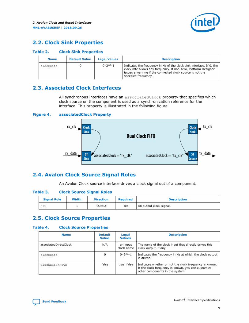
2.3. Associated Clock Interfaces
All synchronous interfaces have an associatedClock property that specifies whichclock source on the component is used as a synchronization reference for theinterface. This property is illustrated in the following figure.
Figure 4. associatedClock Property
Dual Clock FIFO
rx_clk
STSink
ClockSink
tx_clk
STSource
associatedClock = "rx_clk" associatedClock = "tx_clk"
ClockSink
rx_data tx_data
2.4. Avalon Clock Source Signal Roles
An Avalon Clock source interface drives a clock signal out of a component.
Table 3. Clock Source Signal Roles
Signal Role Width Direction Required Description
clk 1 Output Yes An output clock signal.
2.5. Clock Source Properties
Table 4. Clock Source Properties
Name DefaultValue
LegalValues
Description
associatedDirectClock N/A an inputclock name
The name of the clock input that directly drives thisclock output, if any.
clockRate 0 0–232–1 Indicates the frequency in Hz at which the clock outputis driven.
clockRateKnown false true, false Indicates whether or not the clock frequency is known.If the clock frequency is known, you can customizeother components in the system.
2. Avalon Clock and Reset Interfaces
MNL-AVABUSREF | 2018.09.26
Send Feedback Avalon® Interface Specifications
9

2.6. Reset Sink
Table 5. Reset Input Signal RolesThe reset_req signal is an optional signal that you can use to prevent memory content corruption byperforming reset handshake prior to an asynchronous reset assertion.
Signal Role Width Direction Required Description
reset,reset_n
1 Input Yes Resets the internal logic of an interface or componentto a user-defined state. The synchronous properties ofthe reset are defined by the synchronousEdgesparameter.
reset_req 1 input No Early indication of reset signal. This signal acts as aleast a one-cycle warning of pending reset for ROMprimitives. Use reset_req to disable the clock enableor mask the address bus of an on-chip memory, toprevent the address from transitioning when anasynchronous reset input is asserted.
2.7. Reset Sink Interface Properties
Table 6. Reset Input Signal Roles
Name DefaultValue
LegalValues
Description
associatedClock N/A a clockname
The name of a clock to which this interface issynchronized. Required if the value ofsynchronousEdges is DEASSERT or BOTH.
synchronous-Edges DEASSERT NONEDEASSERT
BOTH
Indicates the type of synchronization the reset inputrequires. The following values are defined:• NONE–no synchronization is required because the
component includes logic for internalsynchronization of the reset signal.
• DEASSERT–the reset assertion is asynchronous anddeassertion is synchronous.BOTH–reset assertion and deassertion aresynchronous.
2.8. Associated Reset Interfaces
All synchronous interfaces have an associatedReset property that specifies whichreset signal resets the interface logic.
2.9. Reset Source
Table 7. Reset Output Signal RolesThe reset_req signal is an optional signal that you can use to prevent memory content corruption byperforming reset handshake prior to an asynchronous reset assertion.
Signal Role Width Direction Required Description
resetreset_n
1 Output Yes Resets the internal logic of an interface or componentto a user-defined state.
reset_req 1 Output Optional Enables reset request generation, which is an earlysignal that is asserted before reset assertion. Onceasserted, this cannot be deasserted until the reset iscompleted.
2. Avalon Clock and Reset Interfaces
MNL-AVABUSREF | 2018.09.26
Avalon® Interface Specifications Send Feedback
10

2.10. Reset Source Interface Properties
Table 8. Reset Interface Properties
Name DefaultValue
LegalValues
Description
associatedClock N/A a clockname
The name of a clock to which this interfacesynchronized. Required if the value ofsynchronousEdges is DEASSERT or BOTH.
associatedDirectReset N/A a resetname
The name of the reset input that directly drives thisreset source through a one-to-one link.
associatedResetSinks N/A a resetname
Specifies reset inputs that cause a reset source toassert reset. For example, a reset synchronizer thatperforms an OR operation with multiple reset inputs togenerate a reset output.
synchronousEdges DEASSERT NONE
DEASSERT
BOTH
Indicates the reset output's synchronization. Thefollowing values are defined:• NONE–The reset interface is asynchronous.• DEASSERT–the reset assertion is asynchronous and
deassertion is synchronous.• BOTH–reset assertion and deassertion are
synchronous.
2. Avalon Clock and Reset Interfaces
MNL-AVABUSREF | 2018.09.26
Send Feedback Avalon® Interface Specifications
11

3. Avalon Memory-Mapped Interfaces
3.1. Introduction to Avalon Memory-Mapped Interfaces
You can use Avalon Memory-Mapped (Avalon-MM) interfaces to implement read andwrite interfaces for master and slave components. The following are examples ofcomponents that typically include memory-mapped interfaces:
• Microprocessors
• Memories
• UARTs
• DMAs
• Timers
Avalon-MM interfaces range from simple to complex. For example, SRAM interfacesthat have fixed-cycle read and write transfers have simple Avalon-MM interfaces.Pipelined interfaces capable of burst transfers are complex.
MNL-AVABUSREF | 2018.09.26
Send Feedback
Intel Corporation. All rights reserved. Intel, the Intel logo, Altera, Arria, Cyclone, Enpirion, MAX, Nios, Quartusand Stratix words and logos are trademarks of Intel Corporation or its subsidiaries in the U.S. and/or othercountries. Intel warrants performance of its FPGA and semiconductor products to current specifications inaccordance with Intel's standard warranty, but reserves the right to make changes to any products and servicesat any time without notice. Intel assumes no responsibility or liability arising out of the application or use of anyinformation, product, or service described herein except as expressly agreed to in writing by Intel. Intelcustomers are advised to obtain the latest version of device specifications before relying on any publishedinformation and before placing orders for products or services.*Other names and brands may be claimed as the property of others.
ISO9001:2015Registered

Figure 5. Focus on Avalon-MM Slave TransfersThe following figure shows a typical system, highlighting the Avalon-MM slave interface connection to theinterconnect fabric.
RS-232
Avalon-MM System
Interconnect
EthernetPHY
AvalonSlave Port
Avalon-MMSlave
Avalon-MMSlave
RAMMemory
Avalon-MMMaster
Processor
FlashMemory
TristateConduit
Slave
TristateConduit
Slave
SRAMMemory
Avalon-MMMaster
Avalon-MMMaster
Ethernet MAC Custom Logic
RAMController
UART CustomLogic
FlashController
Avalon-MMSlave
Tristate Conduit Pin Sharer &Tristate Conduit Bridge
Tristate Conduit Slave
Tristate Conduit Master
SRAMController
Avalon-MMSlave
Avalon-MMSlave
CustomLogic
Avalon-MM components typically include only the signals required for the componentlogic.
3. Avalon Memory-Mapped Interfaces
MNL-AVABUSREF | 2018.09.26
Send Feedback Avalon® Interface Specifications
13

Figure 6. Example Slave ComponentThe 16-bit general-purpose I/O peripheral shown in the following figure only responds to write requests. Thiscomponent includes only the slave signals required for write transfers.
Avalon-MM Interface
(Avalon-MM Slave Interface)
Application-Specific
Interface
writedata[15..0]
write
clk
pio_out[15..0]
CLK_EN
D Q
Avalon-MM Peripheral
Each signal in an Avalon-MM slave corresponds to exactly one Avalon-MM signal role.An Avalon-MM interface can use only one instance of each signal role.
3.2. Avalon Memory-Mapped Interface Signal Roles
Signal roles define the signal types that Avalon-MM master and slave ports allow.
This specification does not require all signals to exist in an Avalon-MM interface. Thereis no one signal that is always required. The minimum requirements for an Avalon-MMinterface are readdata for a read-only interface, or writedata and write for awrite-only interface.
The following table lists signal roles for the Avalon-MM interface:
Table 9. Avalon-MM Signal RolesSome Avalon-MM signals can be active high or active low. When active low, the signal name ends with _n.
Signal Role Width Direction Required Description
Fundamental Signals
address 1 - 64 Master →Slave
No Masters: By default, the address signal represents a byteaddress. The value of the address must align to the data width.To write to specific bytes within a data word, the master mustuse the byteenable signal. Refer to the addressUnitsinterface property for word addressing.Slaves: By default, the interconnect translates the byte addressinto a word address in the slave’s address space. From theperspective of the slave, each slave access is for a word of data.For example, address = 0 selects the first word of the slave.address = 1 selects the second word of the slave. Refer to theaddressUnits interface property for byte addressing.
byteenable
byteenable_n
2, 4,8, 16,32,64,128
Master →Slave
No Enables one or more specific byte lanes during transfers oninterfaces of width greater than 8 bits. Each bit in byteenablecorresponds to a byte in writedata and readdata. The masterbit <n> of byteenable indicates whether byte <n> is beingwritten to. During writes, byteenables specify which bytes arebeing written to. Other bytes should be ignored by the slave.During reads, byteenables indicate which bytes the master is
continued...
3. Avalon Memory-Mapped Interfaces
MNL-AVABUSREF | 2018.09.26
Avalon® Interface Specifications Send Feedback
14

Signal Role Width Direction Required Description
reading. Slaves that simply return readdata with no side effectsare free to ignore byteenables during reads. If an interfacedoes not have a byteenable signal, the transfer proceeds as ifall byteenables are asserted.When more than one bit of the byteenable signal is asserted,all asserted lanes are adjacent.
debugaccess 1 Master →Slave
No When asserted, allows the Nios II processor to write on-chipmemories configured as ROMs.
read
read_n
1 Master →Slave
No Asserted to indicate a read transfer. If present, readdata isrequired.
readdata 8, 16,32,64,128,256,512,1024
Slave →Master
No The readdata driven from the slave to the master in responseto a read transfer. Required for interfaces that support reads.
response[1:0]
2 Slave →Master
No The response signal is an optional signal that carries theresponse status.Note: Because the signal is shared, an interface cannot issue or
accept a write response and a read response in the sameclock cycle.
• 00: OKAY—Successful response for a transaction.• 01: RESERVED—Encoding is reserved.• 10: SLAVEERROR—Error from an endpoint slave. Indicates
an unsuccessful transaction.• 11: DECODEERROR—Indicates attempted access to an
undefined location.For read responses:• One response is sent with each readdata. A read burst
length of N results in N responses. Fewer responses are notvalid, even in the event of an error. The response signal valuemay be different for each readdata in the burst.
• The interface must have read control signals. Pipeline supportis possible with the readdatavalid signal.
• On read errors, the corresponding readdata is "don't care".For write responses:• One write response must be sent for each write command. A
write burst results in only one response, which must be sentafter the final write transfer in the burst is accepted.
• If writeresponsevalid is present, all write commandsmust be completed with write responses.
write
write_n
1 Master →Slave
No Asserted to indicate a write transfer. If present, writedata isrequired.
writedata 8, 16,32,64,128,256,512,1024
Master →Slave
No Data for write transfers. The width must be the same as thewidth of readdata if both are present. Required for interfacesthat support writes.
Wait-State Signals
lock 1 Master →Slave
No lock ensures that once a master wins arbitration, the winningmaster maintains access to the slave for multiple transactions.Lock asserts coincident with the first read or write of a locked
continued...
3. Avalon Memory-Mapped Interfaces
MNL-AVABUSREF | 2018.09.26
Send Feedback Avalon® Interface Specifications
15

Signal Role Width Direction Required Description
sequence of transactions. Lock deasserts on the finaltransaction of a locked sequence of transactions. lock assertiondoes not guarantee that arbitration is won. After the lock-asserting master has been granted, that master retains grantuntil lock is deasserted.A master equipped with lock cannot be a burst master.Arbitration priority values for lock-equipped masters are ignored.lock is particularly useful for read-modify-write (RMW)operations. The typical read-modify-write operation includes thefollowing steps:1. Master A asserts lock and reads 32-bit data that has multiple
bit fields.2. Master A deasserts lock, changes one bit field, and writes the
32-bit data back.lock prevents master B from performing a write betweenMaster A’s read and write.
waitrequest
waitrequest_n
1 Slave →Master
No A slave asserts waitrequest when unable to respond to aread or write request. Forces the master to wait until theinterconnect is ready to proceed with the transfer. At the start ofall transfers, a master initiates the transfer and waits untilwaitrequest is deasserted. A master must make noassumption about the assertion state of waitrequest when themaster is idle: waitrequest may be high or low, depending onsystem properties.When waitrequest is asserted, master control signals to theslave must remain constant except for beginbursttransfer.For a timing diagram illustrating the beginbursttransfersignal, refer to the figure in Read Bursts.An Avalon-MM slave may assert waitrequest during idlecycles. An Avalon-MM master may initiate a transaction whenwaitrequest is asserted and wait for that signal to bedeasserted. To avoid system lockup, a slave device should assertwaitrequest when in reset.
Pipeline Signals
readdatavalid
readdatavalid_n
1 Slave →Master
No Used for variable-latency, pipelined read transfers. Whenasserted, indicates that the readdata signal contains valid data.For a read burst with burstcount value <n>, thereaddatavalid signal must be asserted <n> times, once foreach readdata item. There must be at least one cycle of latencybetween acceptance of the read and assertion ofreaddatavalid. For a timing diagram illustrating thereaddatavalid signal, refer to Pipelined Read Transfer withVariable Latency.A slave may assert readdatavalid to transfer data to themaster independently of whether the slave is stalling a newcommand with waitrequest.Required if the master supports pipelined reads. Burstingmasters with read functionality must include thereaddatavalid signal.
writeresponsevalid
1 Slave →Master
No An optional signal. If present, the interface issues writeresponses for write commands.When asserted, the value on the response signal is a valid writeresponse.Writeresponsevalid is only asserted one clock cycle or moreafter the write command is accepted. There is at least a oneclock cycle latency from command acceptance to assertion ofwriteresponsevalid.
Burst Signalscontinued...
3. Avalon Memory-Mapped Interfaces
MNL-AVABUSREF | 2018.09.26
Avalon® Interface Specifications Send Feedback
16
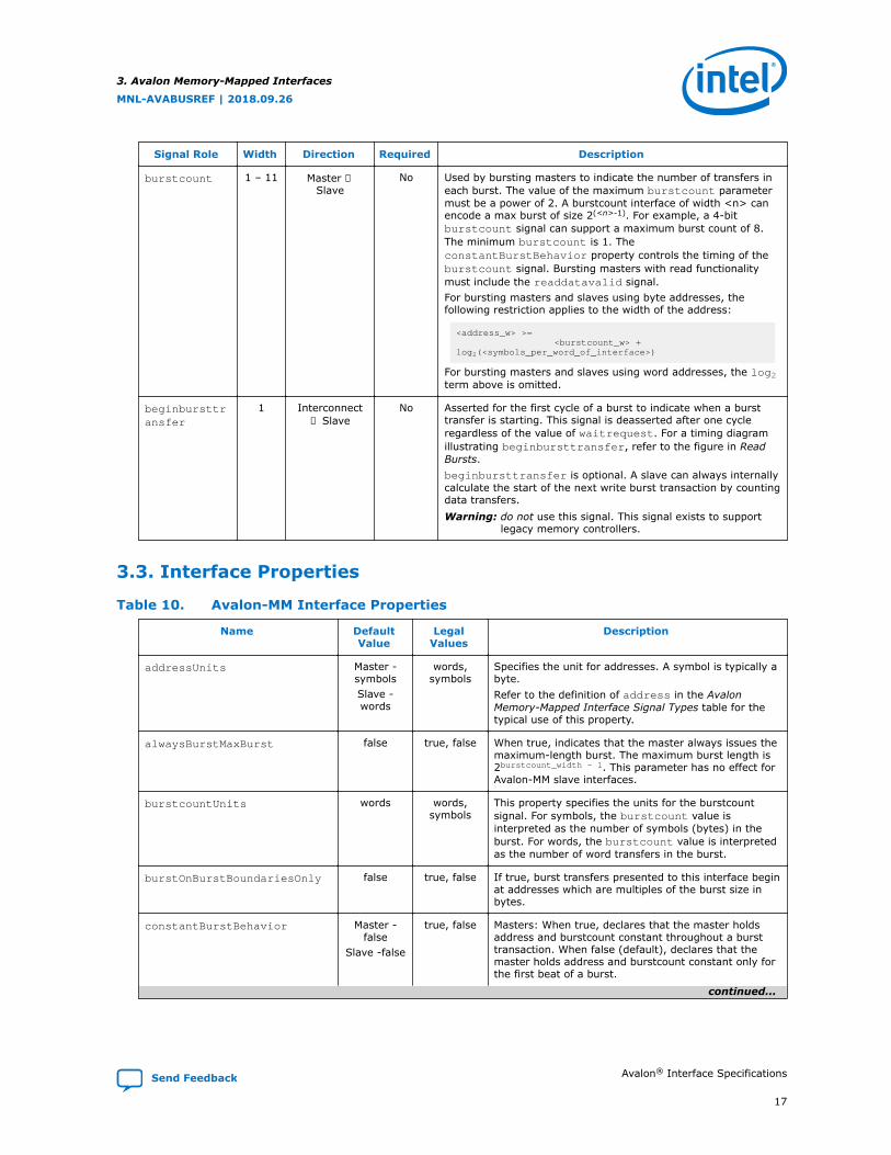
Signal Role Width Direction Required Description
burstcount 1 – 11 Master →Slave
No Used by bursting masters to indicate the number of transfers ineach burst. The value of the maximum burstcount parametermust be a power of 2. A burstcount interface of width <n> canencode a max burst of size 2(<n>-1). For example, a 4-bitburstcount signal can support a maximum burst count of 8.The minimum burstcount is 1. TheconstantBurstBehavior property controls the timing of theburstcount signal. Bursting masters with read functionalitymust include the readdatavalid signal.For bursting masters and slaves using byte addresses, thefollowing restriction applies to the width of the address:
<address_w> >= <burstcount_w> +log2(<symbols_per_word_of_interface>)
For bursting masters and slaves using word addresses, the log2term above is omitted.
beginbursttransfer
1 Interconnect→ Slave
No Asserted for the first cycle of a burst to indicate when a bursttransfer is starting. This signal is deasserted after one cycleregardless of the value of waitrequest. For a timing diagramillustrating beginbursttransfer, refer to the figure in ReadBursts.beginbursttransfer is optional. A slave can always internallycalculate the start of the next write burst transaction by countingdata transfers.Warning: do not use this signal. This signal exists to support
legacy memory controllers.
3.3. Interface Properties
Table 10. Avalon-MM Interface Properties
Name DefaultValue
LegalValues
Description
addressUnits Master -symbolsSlave -words
words,symbols
Specifies the unit for addresses. A symbol is typically abyte.Refer to the definition of address in the AvalonMemory-Mapped Interface Signal Types table for thetypical use of this property.
alwaysBurstMaxBurst false true, false When true, indicates that the master always issues themaximum-length burst. The maximum burst length is2burstcount_width - 1. This parameter has no effect forAvalon-MM slave interfaces.
burstcountUnits words words,symbols
This property specifies the units for the burstcountsignal. For symbols, the burstcount value isinterpreted as the number of symbols (bytes) in theburst. For words, the burstcount value is interpretedas the number of word transfers in the burst.
burstOnBurstBoundariesOnly false true, false If true, burst transfers presented to this interface beginat addresses which are multiples of the burst size inbytes.
constantBurstBehavior Master -false
Slave -false
true, false Masters: When true, declares that the master holdsaddress and burstcount constant throughout a bursttransaction. When false (default), declares that themaster holds address and burstcount constant only forthe first beat of a burst.
continued...
3. Avalon Memory-Mapped Interfaces
MNL-AVABUSREF | 2018.09.26
Send Feedback Avalon® Interface Specifications
17

Name DefaultValue
LegalValues
Description
Slaves: When true, declares that the slave expectsaddress and burstcount to be held constant throughouta burst. When false (default), declares that the slavesamples address and burstcount only on the first beatof a burst.
holdTime(1) 0 0 – 1000cycles
Specifies time in timingUnits between thedeassertion of write and the deassertion of addressand data. (Only applies to write transactions.)
linewrapBursts false true, false Some memory devices implement a wrapping burstinstead of an incrementing burst. When a wrappingburst reaches a burst boundary, the address wrapsback to the previous burst boundary. Only the low-order bits are required for address counting. Forexample, a wrapping burst to address 0xC with burstboundaries every 32 bytes across a 32-bit interfacewrites to the following addresses:• 0xC• 0x10• 0x14• 0x18• 0x1C• 0x0• 0x4• 0x8
maximumPendingReadTransactions (1)
1(2) 1 – 64 Slaves: This parameter is the maximum number ofpending reads that the slave can queue. The valuemust be non-zero for any slave with thereaddatavalid signal.Refer to Pipelined Read Transfer with Variable Latencyfor a timing diagram that illustrates this property andfor additional information about using waitrequestand readdatavalid with multiple outstanding reads.Masters: This property is the maximum number ofoutstanding read transactions that the master cangenerate.Note: Do not set this parameter to 0. (For backwards
compatibility, the software supports aparameter setting of 0. However, you shouldnot use this setting in new designs).
maximumPendingWriteTransactions
0 1 – 64 The maximum number of pending non-posted writesthat a slave can accept or a master can issue. A slaveasserts waitrequest once the interconnect reachesthis limit, and the master stops issuing commands.The default value is 0, which allows unlimited pendingwrite transactions for a master that supports writeresponses. A slave that supports write responses mustset this to a non-zero value.
minimumResponseLatency 1 For interfaces that support readdatavalid orwriteresponsevalid, specifies the minimumnumber of cycles between a read or write commandand the response to the command.
readLatency(1) 0 0 – 63 Read latency for fixed-latency Avalon-MM slaves. For atiming diagram that uses a fixed latency read, refer toPipelined Read Transfers with Fixed Latency.
continued...
3. Avalon Memory-Mapped Interfaces
MNL-AVABUSREF | 2018.09.26
Avalon® Interface Specifications Send Feedback
18
Name DefaultValue
LegalValues
Description
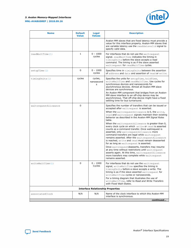
Avalon-MM slaves that are fixed latency must provide avalue for this interface property. Avalon-MM slaves thatare variable latency use the readdatavalid signal tospecify valid data.
readWaitTime(1) 1 0 – 1000cycles
For interfaces that do not use the waitrequestsignal. readWaitTime indicates the timing intimingUnits before the slave accepts a readcommand. The timing is as if the slave assertedwaitrequest for readWaitTime cycles.
setupTime(1) 0 0 – 1000cycles
Specifies time in timingUnits between the assertionof address and data and assertion of read or write.
timingUnits(1) cycles cycles,nanosecond
s
Specifies the units for setupTime, holdTime,writeWaitTime and readWaitTime. Use cycles forsynchronous devices and nanoseconds forasynchronous devices. Almost all Avalon-MM slavedevices are synchronous.An Avalon-MM component that bridges from an Avalon-MM slave interface to an off-chip device may beasynchronous. That off-chip device might have a fixedsettling time for bus turnaround.
waitrequestAllowance 0 Specifies the number of transfers that can be issued oraccepted after waitrequest is asserted.When the waitrequestAllowance is 0, the write,read and waitrequest signals maintain their existingbehavior as described in the Avalon-MM Signal Rolestable.When the waitrequestAllowance is greater than 0,every clock cycle on which write or read is assertedcounts as a command transfer. Once waitrequest isasserted, only waitrequestAllowance morecommand transfers are legal while waitrequestremains asserted. After the waitrequestAllowanceis reached, write and read must remain deassertedfor as long as waitrequest is asserted.Once waitrequestdeasserts, transfers may resumeat any time without restrictions until waitrequestasserts again. At this time, waitrequestAllowancemore transfers may complete while waitrequestremains asserted.
writeWaitTime(1) 0 0 – 1000Cycles
For interfaces that do not use the waitrequestsignal, writeWaitTime specifies the timing intimingUnits before a slave accepts a write. Thetiming is as if the slave asserted waitrequest forwriteWaitTime cycles or nanoseconds.For a timing diagram that illustrates the use ofwriteWaitTime, refer to Read and Write Transferswith Fixed Wait-States.
Interface Relationship Properties
associatedClock N/A N/A Name of the clock interface to which this Avalon-MMinterface is synchronous.
continued...
3. Avalon Memory-Mapped Interfaces
MNL-AVABUSREF | 2018.09.26
Send Feedback Avalon® Interface Specifications
19

Name DefaultValue
LegalValues
Description
associatedReset N/A N/A Name of the reset interface which resets the logic onthis Avalon-MM interface.
bridgesToMaster 0 Avalon-MMMaster
name onthe same
component
An Avalon-MM bridge consists of a slave and a master,and has the property that an access to the slaverequesting a byte or bytes causes the same byte orbytes to be requested by the master. The Avalon-MMPipeline Bridge in the Platform Designer componentlibrary implements this functionality.
Notes:1. Although this property characterizes a slave device, masters can declare this property to enable direct connections
between matching master and slave interfaces.2. If a slave interface accepts more read transfers than allowed, the interconnect pending read FIFO may overflow with
unpredictable results. The slave may lose readdata or route readdata to the wrong master interface. Or, the systemmay lock up. The slave interface must assert waitrequest to prevent this overflow.
Related Information
• Avalon Memory-Mapped Interface Signal Roles on page 14
• Read and Write Responses on page 34
• Pipelined Read Transfer with Variable Latency on page 28
• Pipelined Read Transfers with Fixed Latency on page 29
• Read and Write ResponsesIn Platform Designer User Guide: Intel Quartus® Prime Pro Edition
3.4. Timing
The Avalon-MM interface is synchronous. Each Avalon-MM interface is synchronized toan associated clock interface. Signals may be combinational if they are driven fromthe outputs of registers that are synchronous to the clock signal. This specificationdoes not dictate how or when signals transition between clock edges. Timing diagramsare devoid of fine-grained timing information.
3.5. Transfers
This section defines two basic concepts before introducing the transfer types:
• Transfer—A transfer is a read or write operation of a word or one or more symbolof data. Transfers occur between an Avalon-MM interface and the interconnect.Transfers take one or more clock cycles to complete.
Both masters and slaves are part of a transfer. The Avalon-MM master initiates thetransfer and the Avalon-MM slave responds.
• Master-slave pair—This term refers to the master interface and slave interfaceinvolved in a transfer. During a transfer, the master interface control and datasignals pass through the interconnect fabric and interact with the slave interface.
3. Avalon Memory-Mapped Interfaces
MNL-AVABUSREF | 2018.09.26
Avalon® Interface Specifications Send Feedback
20

3.5.1. Typical Read and Write Transfers
This section describes a typical Avalon-MM interface that supports read and writetransfers with slave-controlled waitrequest. The slave can stall the interconnect foras many cycles as required by asserting the waitrequest signal. If a slave useswaitrequest for either read or write transfers, the slave must use waitrequest forboth.
A slave typically receives address, byteenable, read or write, and writedataafter the rising edge of the clock. A slave asserts waitrequest before the rising clockedge to hold off transfers. When the slave asserts waitrequest, the transfer isdelayed. While waitrequest is asserted, the address and other control signals areheld constant. Transfers complete on the rising edge of the first clk after the slaveinterface deasserts waitrequest.
There is no limit on how long a slave interface can stall. Therefore, you must ensurethat a slave interface does not assert waitrequest indefinitely. The following figureshows read and write transfers using waitrequest.
Note: waitrequest can be decoupled from the read and write request signals.waitrequest may be asserted during idle cycles. An Avalon-MM master may initiatea transaction when waitrequest is asserted and wait for that signal to bedeasserted. Decoupling waitrequest from read and write requests may improvesystem timing. Decoupling eliminates a combinational loop including the read,write, and waitrequest signals. If even more decoupling is required, use thewaitrequestAllowance property. waitrequestAllowance is available startingwith the Quartus® Prime Pro v17.1 Stratix® 10 ES Editions release.
Figure 7. Read and Write Transfers with Waitrequest
clk
address
byteenable
read
write
waitrequest
readdata
writedata
address
byteenable
readdata
1 2 3 4 5 76
responseresponse
writedata
3. Avalon Memory-Mapped Interfaces
MNL-AVABUSREF | 2018.09.26
Send Feedback Avalon® Interface Specifications
21
The numbers in this timing diagram, mark the following transitions:
1. address, byteenable, and read are asserted after the rising edge of clk. Theslave asserts waitrequest, stalling the transfer.
2. waitrequest is sampled. Because waitrequest is asserted, the cycle becomesa wait-state. address, read, write, and byteenable remain constant.
3. The slave deasserts waitrequest after the rising edge of clk. The slave assertsreaddata and response.
4. The master samples readdata, response and deasserted waitrequestcompleting the transfer.
5. address, writedata, byteenable, and write signals are asserted after therising edge of clk. The slave asserts waitrequest stalling the transfer.
6. The slave deasserts waitrequest after the rising edge of clk.
7. The slave captures write data ending the transfer.
3. Avalon Memory-Mapped Interfaces
MNL-AVABUSREF | 2018.09.26
Avalon® Interface Specifications Send Feedback
22

3.5.2. Transfers Using the waitrequestAllowance Property
The waitrequestAllowance property specifies the number of transfers an Avalon-MM master can issue or an Avalon-MM slave must accept after the waitrequestsignal is asserted. waitrequestAllowance is available starting with the IntelQuartus Prime 17.1 software release.
The default value of waitrequestAllowance is 0, which corresponds to thebehavior described in Typical Read and Write Transfers, where waitrequestassertion stops the current transfer from being issued or accepted.
An Avalon-MM slave with a waitrequestAllowance greater than 0 would typicallyassert waitrequest when its internal buffer can only acceptwaitrequestAllowance more entries before becoming full. Avalon-MM masters witha waitrequestAllowance greater than 0 have waitrequestAllowance additionalcycles to stop sending transfers, which allows more pipelining in the master logic. Themaster must deassert the read or write signal when the waitrequestallowancehas been spent.
Values of waitrequestAllowance greater than 0 support high-speed design whereimmediate forms of backpressure may result in a drop in the maximum operatingfrequency (FMAX) often due to combinatorial logic in the control path. An Avalon-MMslave must support all possible transfer timings that are legal for itswaitrequestAllowance value. For example, a slave with waitrequestAllowance= 2 must be able to accept any of the master transfer waveforms shown in thefollowing examples.
Related Information
Typical Read and Write Transfers on page 21
3.5.2.1. waitrequestAllowance Equals Two
The following timing diagram illustrates timing for an Avalon-MM> master that hastwo clock cycles to start and stop sending transfers after the Avalon-MM> slavedeasserts or asserts waitrequest, respectively.
Figure 8. Master write: waitrequestAllowance Equals Two Clock Cycles
clock
write
waitrequest
data[7:0] A0 A1 A2 A3 A4 B0 B1 B3
1 2 3 4 5 6
3. Avalon Memory-Mapped Interfaces
MNL-AVABUSREF | 2018.09.26
Send Feedback Avalon® Interface Specifications
23

The markers in this figure mark the following events:
1. The Avalon-MM> master drives write and data.
2. The Avalon-MM> slave asserts waitrequest. Because thewaitrequestAllowance is 2, the master is able to complete the 2 additionaldata transfers.
3. The master deasserts write as required because the slave is assertingwaitrequest for a third cycle.
4. The Avalon-MM> master drives write and data. The slave is not assertingwaitrequest. The writes complete.
5. The Avalon master drives write and data even though the slave is assertingwaitrequest. Because the waitrequestAllowance is 2 cycles, the writecompletes.
6. The Avalon master drives write and data. The slave is not assertingwaitrequest. The write completes.
3.5.2.2. waitrequestAllowance Equals One
The following timing diagram illustrates timing for an Avalon-MM master that has oneclock cycle to start and stop sending transfers after the Avalon-MM slave deasserts orasserts waitrequest, respectively:
Figure 9. Master Write: waitrequestAllowance Equals One Clock Cycle
clk
write
waitrequest
data[7:0] A0 A1 A2 A3 A4 B0 B1 B2 B3
1 2 3 4 5 6 7 8
The numbers in this figure mark the following events:
1. The Avalon-MM master drives write and data.
2. The Avalon-MM slave asserts waitrequest. Because thewaitrequestAllowance is 1, the master can complete the write.
3. The master deasserts write because the slave is asserting waitrequest for asecond cycle.
4. The Avalon-MM master drives write and data. The slave is not assertingwaitrequest. The writes complete.
5. The slave asserts waitrequest. Because the waitrequestAllowance is 1cycle, the write completes.
3. Avalon Memory-Mapped Interfaces
MNL-AVABUSREF | 2018.09.26
Avalon® Interface Specifications Send Feedback
24

6. Avalon-MM master drives write and data. The slave is not assertingwaitrequest. The write completes.
7. The Avalon-MM slave asserts waitrequest. Because thewaitrequestAllowance is 1, the master can complete one additional datatransfer.
8. The Avalon master drives write and data. The slave is not assertingwaitrequest. The write completes.
3.5.2.3. waitrequestAllowance Equals Two - Not Recommended
The following diagram illustrates timing for an Avalon-MM> master that can send twotransfers after waitrequest is asserted.
This timing is legal, but not recommended. In this example the master counts thenumber of transactions instead of the number of clock cycles. This approach requires acounter that makes the implementation more complex and may affect timing closure.When the master determines when to drive transactions with the waitrequest signaland a constant number of cycles, the master starts or stops transactions based on theregistered signals.
Figure 10. waitrequestAllowance Equals Two Transfers
clk
write
waitrequest
data
1 2 3 4 5 6 7
The numbers in this figure mark the following events:
1. The Avalon-MM> master asserts write and drives data.
2. The Avalon-MM> slave asserts waitrequest.
3. The Avalon-MM> master drives write and data. Because thewaitrequestAllowance is 2, the master drives data in 2 consecutive cycles.
4. The Avalon-MM> master deasserts write because the master has spent the 2-transfer waitrequestAllowance.
5. The Avalon-MM> master issues a write as soon as waitrequest is deasserted.
6. The Avalon-MM> master drives write and data. The slave asserts waitrequestfor 1 cycle.
7. In response to waitrequest, the Avalon-MM> master holds data for 2 cycles.
3.5.2.4. waitrequestAllowance Compatibility for Avalon-MM Master and SlaveInterfaces
Avalon-MM masters and slaves that support the waitrequest signal supportbackpressure. Masters with backpressure can always connect to slaves withoutbackpressure. Masters without backpressure cannot connect to slaves withbackpressure.
3. Avalon Memory-Mapped Interfaces
MNL-AVABUSREF | 2018.09.26
Send Feedback Avalon® Interface Specifications
25
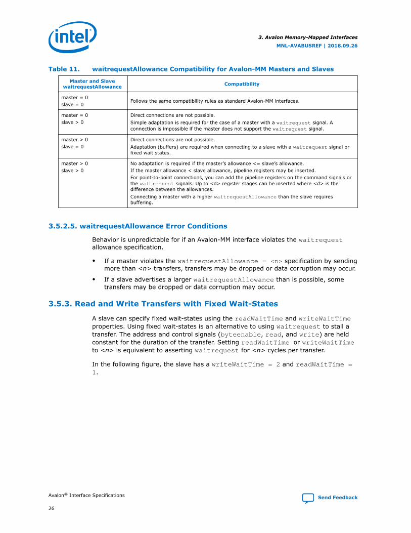
Table 11. waitrequestAllowance Compatibility for Avalon-MM Masters and Slaves
Master and SlavewaitrequestAllowance Compatibility
master = 0slave = 0
Follows the same compatibility rules as standard Avalon-MM interfaces.
master = 0slave > 0
Direct connections are not possible.Simple adaptation is required for the case of a master with a waitrequest signal. Aconnection is impossible if the master does not support the waitrequest signal.
master > 0slave = 0
Direct connections are not possible.Adaptation (buffers) are required when connecting to a slave with a waitrequest signal orfixed wait states.
master > 0slave > 0
No adaptation is required if the master’s allowance <= slave’s allowance.If the master allowance < slave allowance, pipeline registers may be inserted.For point-to-point connections, you can add the pipeline registers on the command signals orthe waitrequest signals. Up to <d> register stages can be inserted where <d> is thedifference between the allowances.Connecting a master with a higher waitrequestAllowance than the slave requiresbuffering.
3.5.2.5. waitrequestAllowance Error Conditions
Behavior is unpredictable for if an Avalon-MM interface violates the waitrequestallowance specification.
• If a master violates the waitrequestAllowance = <n> specification by sendingmore than <n> transfers, transfers may be dropped or data corruption may occur.
• If a slave advertises a larger waitrequestAllowance than is possible, sometransfers may be dropped or data corruption may occur.
3.5.3. Read and Write Transfers with Fixed Wait-States
A slave can specify fixed wait-states using the readWaitTime and writeWaitTimeproperties. Using fixed wait-states is an alternative to using waitrequest to stall atransfer. The address and control signals (byteenable, read, and write) are heldconstant for the duration of the transfer. Setting readWaitTime or writeWaitTimeto <n> is equivalent to asserting waitrequest for <n> cycles per transfer.
In the following figure, the slave has a writeWaitTime = 2 and readWaitTime =1.
3. Avalon Memory-Mapped Interfaces
MNL-AVABUSREF | 2018.09.26
Avalon® Interface Specifications Send Feedback
26

Figure 11. Read and Write Transfer with Fixed Wait-States at the Slave Interface
clk
address
byteenable byteenable
read
write
readdata
writedata
address address
readdata
response response
writedata
4 51 2 3
The numbers in this timing diagram mark the following transitions:
1. The master asserts address and read on the rising edge of clk.
2. The next rising edge of clk marks the end of the first and only wait-state cycle.The readWaitTime is 1.
3. The slave asserts readdata and response on the rising edge of clk. The readtransfer ends.
4. writedata, address, byteenable, and write signals are available to theslave.
5. The write transfer ends after 2 wait-state cycles.
Transfers with a single wait-state are commonly used for multicycle off-chipperipherals. The peripheral captures address and control signals on the rising edge ofclk. The peripheral has one full cycle to return data.
Components with zero wait-states are allowed. However, components with zero wait-states may decrease the achievable frequency. Zero wait-states require thecomponent to generate the response in the same cycle that the request waspresented.
3.5.4. Pipelined Transfers
Avalon-MM pipelined read transfers increase the throughput for synchronous slavedevices that require several cycles to return data for the first access. Such devices cantypically return one data value per cycle for some time thereafter. New pipelined readtransfers can start before readdata for the previous transfers is returned.
A pipelined read transfer has an address phase and a data phase. A master initiates atransfer by presenting the address during the address phase. A slave fulfills thetransfer by delivering the data during the data phase. The address phase for a newtransfer (or multiple transfers) can begin before the data phase of a previous transfercompletes. The delay is called pipeline latency. The pipeline latency is the durationfrom the end of the address phase to the beginning of the data phase.
3. Avalon Memory-Mapped Interfaces
MNL-AVABUSREF | 2018.09.26
Send Feedback Avalon® Interface Specifications
27
Transfer timing for wait-states and pipeline latency have the following key differences:
• Wait-states—Wait-states determine the length of the address phase. Wait-stateslimit the maximum throughput of a port. If a slave requires one wait-state torespond to a transfer request, the port requires two clock cycles per transfer.
• Pipeline Latency—Pipeline latency determines the time until data is returnedindependently of the address phase. A pipelined slave with no wait-states cansustain one transfer per cycle. However, the slave may require several cycles oflatency to return the first unit of data.
Wait-states and pipelined reads can be supported concurrently. Pipeline latency can beeither fixed or variable.
3.5.4.1. Pipelined Read Transfer with Variable Latency
After capturing address and control signals, an Avalon-MM pipelined slave takes one ormore cycles to produce data. A pipelined slave may have multiple pending readtransfers at any given time.
Variable-latency pipelined read transfers:
• Require one additional signal, readdatavalid, that indicates when read data isvalid.
• Include the same set of signals as non-pipelined read transfers.
In variable-latency pipelined read transfers, Slave peripherals that usereaddatavalid are considered pipelined with variable latency. The readdata andreaddatavalid signals corresponding to a read command can be asserted the cycleafter that read command is asserted, at the earliest.
The slave must return readdata in the same order that the read commands areaccepted. Pipelined slave ports with variable latency must use waitrequest. Theslave can assert waitrequest to stall transfers to maintain an acceptable number ofpending transfers. A slave may assert readdatavalid to transfer data to the masterindependently of whether the slave is stalling a new command with waitrequest.
Note: The maximum number of pending transfers is a property of the slave interface. Theinterconnect fabric builds logic to route readdata to requesting masters using thisnumber. The slave interface, not the interconnect fabric, must track the number ofpending reads. The slave must assert waitrequest to prevent the number ofpending reads from exceeding the maximum number. If a slave haswaitrequestAllowance > 0, the slave must assert waitrequest early enough sothat the total pending transfers, including those accepted while waitrequest isasserted, does not exceed the maximum number of pending transfers specified.
3. Avalon Memory-Mapped Interfaces
MNL-AVABUSREF | 2018.09.26
Avalon® Interface Specifications Send Feedback
28

Figure 12. Pipelined Read Transfers with Variable Latency
The following figure shows several slave read transfers. The slave is pipelined with variable latency. In thisfigure, the slave can accept a maximum of two pending transfers. The slave uses waitrequest to avoidoverrunning this maximum.
clk
address
read
waitrequest
readdata
readdatavalid
addr1 addr2 addr3 addr4 addr5
data 1 data2 data 3 data4 data5
1 2 3 4 6 115 9 1087
The numbers in this timing diagram, mark the following transitions:
1. The master asserts address and read, initiating a read transfer.
2. The slave captures addr1.
3. The slave captures addr2.
4. The slave asserts waitrequest because the slave has already accepted amaximum of two pending reads, causing the third transfer to stall.
5. The slave asserts data1, the response to addr1. The slave deassertswaitrequest.
6. The slave captures addr3. The interconnect captures data1. The interconnectcaptures data1.
7. The slave captures addr4. The interconnect captures data2.
8. The slave drives readdatavalid and readdata in response to the third readtransfer.
9. The slave captures addr5. The interconnect captures data3. The read signal isdeasserted. The value of waitrequest is no longer relevant.
10. The interconnect captures data4.
11. The slave drives data5 and asserts readdatavalid completing the data phasefor the final pending read transfer.
If the slave cannot handle a write transfer while processing pending read transfers,the slave must assert waitrequest and stall the write operation until the pendingread transfers have completed. The Avalon-MM specification does not define the valueof readdata in the event that a slave accepts a write transfer to the same address asa currently pending read transfer.
3.5.4.2. Pipelined Read Transfers with Fixed Latency
The address phase for fixed latency read transfers is identical to the variable latencycase. After the address phase, a pipelined slave with fixed read latency takes a fixednumber of clock cycles to return valid readdata. The readWaitTime propertyspecifies the number of clock cycles to return valid readdata. The interconnectcaptures readdata on the appropriate rising clock edge, ending the data phase.
3. Avalon Memory-Mapped Interfaces
MNL-AVABUSREF | 2018.09.26
Send Feedback Avalon® Interface Specifications
29
During the address phase, the slave can assert waitrequest to hold off the transfer.Or, the slave specifies the readWaitTime for a fixed number of wait states. Theaddress phase ends on the next rising edge of clk after wait states, if any.
During the data phase, the slave drives readdata after a fixed latency. For a readlatency of <n>, the slave must present valid readdata on the <nth> rising edge ofclk after the end of the address phase.
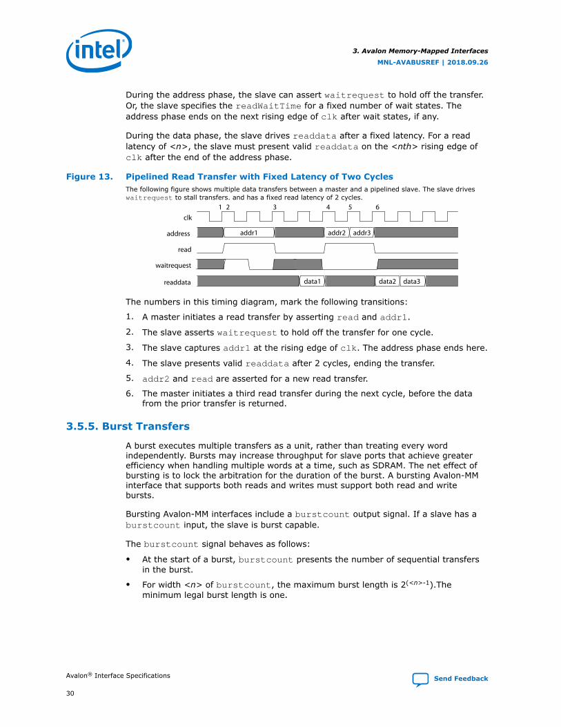
Figure 13. Pipelined Read Transfer with Fixed Latency of Two CyclesThe following figure shows multiple data transfers between a master and a pipelined slave. The slave driveswaitrequest to stall transfers. and has a fixed read latency of 2 cycles.
clk
address
read
waitrequest
readdata
addr1 addr2 addr3
data1 data2 data3
1 2 3 4 5 6
The numbers in this timing diagram, mark the following transitions:
1. A master initiates a read transfer by asserting read and addr1.
2. The slave asserts waitrequest to hold off the transfer for one cycle.
3. The slave captures addr1 at the rising edge of clk. The address phase ends here.
4. The slave presents valid readdata after 2 cycles, ending the transfer.
5. addr2 and read are asserted for a new read transfer.
6. The master initiates a third read transfer during the next cycle, before the datafrom the prior transfer is returned.
3.5.5. Burst Transfers
A burst executes multiple transfers as a unit, rather than treating every wordindependently. Bursts may increase throughput for slave ports that achieve greaterefficiency when handling multiple words at a time, such as SDRAM. The net effect ofbursting is to lock the arbitration for the duration of the burst. A bursting Avalon-MMinterface that supports both reads and writes must support both read and writebursts.
Bursting Avalon-MM interfaces include a burstcount output signal. If a slave has aburstcount input, the slave is burst capable.
The burstcount signal behaves as follows:
• At the start of a burst, burstcount presents the number of sequential transfersin the burst.
• For width <n> of burstcount, the maximum burst length is 2(<n>-1).Theminimum legal burst length is one.
3. Avalon Memory-Mapped Interfaces
MNL-AVABUSREF | 2018.09.26
Avalon® Interface Specifications Send Feedback
30

To support slave read bursts, a slave must also support:
• Wait states with the waitrequest signal.
• Pipelined transfers with variable latency with the readdatavalid signal.
At the start of a burst, the slave sees the address and a burst length value onburstcount. For a burst with an address of <a> and a burstcount value of <b>,the slave must perform <b> consecutive transfers starting at address <a>. The burstcompletes after the slave receives (write) or returns (read) the <bth> word of data.The bursting slave must capture address and burstcount only once for each burst.The slave logic must infer the address for all but the first transfers in the burst. Aslave can also use the input signal beginbursttransfer, which the interconnectasserts on the first cycle of each burst.
3.5.5.1. Write Bursts
These rules apply when a write burst begins with burstcount greater than one:
• When a burstcount of <n> is presented at the beginning of the burst, the slavemust accept <n> successive units of writedata to complete the burst.Arbitration between the master-slave pair remains locked until the burstcompletes. This lock guarantees that no other master can execute transactions onthe slave until the write burst completes.
• The slave must only capture writedata when write asserts. During the burst,the master can deassert write indicating that writedata is invalid. Deassertingwrite does not terminate the burst. The write deassertion delays the burst andno other master can access the slave, reducing the transfer efficiency.
• The slave delays a transfer by asserting waitrequest forcing writedata,write, burstcount, and byteenable to be held constant.
• The functionality of the byteenable signal is the same for bursting and non-bursting slaves. For a 32-bit master burst-writing to a 64-bit slave, starting atbyte address 4, the first write transfer seen by the slave is at its address 0, withbyteenable = 8'b11110000. The byteenables can change for differentwords of the burst.
• The byteenable signals do not all have to be asserted. A burst master writingpartial words can use the byteenable signal to identify the data being written.
• Writes with byteenable signals being all 0's are simply passed on to the Avalon-MM slave as valid transactions.
• The constantBurstBehavior property specifies the behavior of the burstsignals.
— When constantBurstBehavior is true for a master, the master holdsaddress and burstcount stable throughout a burst. When true for a slave,constantBurstBehavior declares that the slave expects address andburstcount to be held stable throughout a burst.
— When constantBurstBehavior is false, the master holds address andburstcount stable only for the first transaction of a burst. WhenconstantBurstBehavior is false, the slave samples address andburstcount only on the first transaction of a burst.
3. Avalon Memory-Mapped Interfaces
MNL-AVABUSREF | 2018.09.26
Send Feedback Avalon® Interface Specifications
31

Figure 14. Write Burst with constantBurstBehavior Set to False for Master and SlaveThe following figure demonstrates a slave write burst of length 4. In this example, the slave assertswaitrequest twice delaying the burst.
clk
address
beginbursttransfer
burstcount
write
writedata
waitrequest
addr1
4
data1 data2 data3 data4
1 2 3 4 5 76 8
The numbers in this timing diagram mark the following transitions:
1. The master asserts address, burstcount, write, and drives the first unit ofwritedata.
2. The slave immediately asserts waitrequest, indicating that the slave is notready to proceed with the transfer.
3. waitrequest is low. The slave captures addr1, burstcount, and the first unitof writedata. On subsequent cycles of the transfer, address and burstcountare ignored.
4. The slave captures the second unit of data at the rising edge of clk.
5. The burst is paused while write is deasserted.
6. The slave captures the third unit of data at the rising edge of clk.
7. The slave asserts waitrequest. In response, all outputs are held constantthrough another clock cycle.
8. The slave captures the last unit of data on this rising edge of clk. The slave writeburst ends.
In the figure above, the beginbursttransfer signal is asserted for the first clockcycle of a burst and is deasserted on the next clock cycle. Even if the slave assertswaitrequest, the beginbursttransfer signal is only asserted for the first clockcycle.
Related Information
Interface Properties on page 17
3.5.5.2. Read Bursts
Read bursts are similar to pipelined read transfers with variable latency. A read bursthas distinct address and data phases. readdatavalid indicates when the slave ispresenting valid readdata. Unlike pipelined read transfers, a single read burstaddress results in multiple data transfers.
3. Avalon Memory-Mapped Interfaces
MNL-AVABUSREF | 2018.09.26
Avalon® Interface Specifications Send Feedback
32

These rules apply to read bursts:
• When a master connects directly to a slave, a burstcount of <n> means theslave must return <n> words of readdata to complete the burst. For caseswhere interconnect links the master and slave pair, the interconnect may suppressread commands sent from the master to the slave. For example, if the mastersends a read command with a byteenable value of 0, the interconnect maysuppress the read. As a result, the slave does not respond to the read command.
• The slave presents each word by providing readdata and assertingreaddatavalid for a cycle. Deassertion of readdatavalid delays but does notterminate the burst data phase.
• For reads with a burstcount > 1, Intel recommends asserting all byteenables.
Note: Intel recommends that burst capable slaves not have read side effects. (Thisspecification does not guarantee how many bytes a master reads from the slave inorder to satisfy a request.)
Figure 15. Read BurstThe following figure illustrates a system with two bursting masters accessing a slave. Note that Master B candrive a read request before the data has returned for Master A.
clk
address
read
beginbursttransfer
waitrequest
burstcount
readdatavalid
readdata
A0 (master A) A1 (master B)
4 2
D(A0) D(A0+1) D(A0+2) D(A0+3) D(A1) D(A1+1)
2 3 5 61 4
The numbers in this timing diagram, mark the following transitions:
1. Master A asserts address (A0), burstcount, and read after the rising edge ofclk. The slave asserts waitrequest, causing all inputs exceptbeginbursttransfer to be held constant through another clock cycle.
2. The slave captures A0 and burstcount at this rising edge of clk. A new transfercould start on the next cycle.
3. Master B drives address (A1), burstcount, and read. The slave assertswaitrequest, causing all inputs except beginbursttransfer to be heldconstant. The slave could have returned read data from the first read request atthis time, at the earliest.
4. The slave presents valid readdata and asserts readdatavalid, transferring thefirst word of data for master A.
5. The second word for master A is transferred. The slave deasserts readdatavalidpausing the read burst. The slave port can keep readdatavalid deasserted foran arbitrary number of clock cycles.
6. The first word for master B is returned.
3. Avalon Memory-Mapped Interfaces
MNL-AVABUSREF | 2018.09.26
Send Feedback Avalon® Interface Specifications
33

3.5.5.3. Line–Wrapped Bursts
Processors with instruction caches gain efficiency by using line-wrapped bursts. Whena processor requests data that is not in the cache, the cache controller must refill theentire cache line. For a processor with a cache line size of 64 bytes, a cache misscauses 64 bytes to be read from memory. If the processor reads from address 0xCwhen the cache miss occurred, then an inefficient cache controller could issue a burstat address 0, resulting in data from read addresses 0x0, 0x4, 0x8, 0xC, 0x10, 0x14,0x18, . . . 0x3C. The requested data is not available until the fourth read. With line-wrapping bursts, the address order is 0xC, 0x10, 0x14, 0x18, . . . 0x3C, 0x0, 0x4,and 0x8. The requested data is returned first. The entire cache line is eventuallyrefilled from memory.
3.5.6. Read and Write Responses
For any Avalon-MM slave, commands must be processed in a hazard-free manner.Read and write responses issue in the order in which commands they were accepted.
3.5.6.1. Transaction Order for Avalon-MM Read and Write Responses (Mastersand Slaves)
For any Avalon-MM master:
• The Avalon Interface Specifications guarantees that commands to the same slavereach the slave in command issue order, and the slave responds in command issueorder.
• Different slaves may receive and respond to commands in a different order thanwhich the master issues them. When successful, the slave responds in commandissue order.
• Responses (if present) return in command issue order, regardless of whether theread or write commands are for the same or different slaves.
• The Avalon Interface Specifications does not guarantee transaction order betweendifferent masters.
3.5.6.2. Avalon-MM Read and Write Responses Timing Diagram
The following diagram shows command acceptance and command issue order forAvalon-MM read and write responses. Because the read and write interfaces share theresponse signal, an interface cannot issue or accept a write response and a readresponse in the same clock cycle.
Read responses, send one response for each readdata. A read burst length of <N>results in <N> responses.
Write responses, send one response for each write command. A write burst results inonly one response. The slave interface sends the response after accepting the finalwrite transfer in the burst. When an interface includes the writeresponsevalidsignal, all write commands must complete with write responses.
3. Avalon Memory-Mapped Interfaces
MNL-AVABUSREF | 2018.09.26
Avalon® Interface Specifications Send Feedback
34

Figure 16. Avalon-MM Read and Write Responses Timing Diagram
clkR0 W0 W1 R1
R1
address
read
write
readdatavalid
writeresponsevalid
response R0 W0 W1
3.5.6.2.1. minimumResponseLatency Timing Diagram with readdatavalid orwriteresponsevalid
For interfaces with readdatavalid or writeresponsevalid, the default a one-cycle minimumResponseLatency can lead to difficulty closing timing on Avalon-MMmasters.
The following timing diagrams show the behavior for a minimumResponseLatency of1 or 2 cycles. Note that the actual response latency can also be greater than theminimum allowed value as these timing diagrams illustrate.
Figure 17. minimumResponseLatency Equals One Cycle
clk
read
readdatavalid
data
1 cycle minimum response latency
Figure 18. minimumResponseLatency Equals Two Cycles
clk
read
2 cycles minimumResponseLatency
readdatavalid
data
Compatibility
Interfaces with the same minimumResponseLatency are interoperable without anyadaptation. If the master has a higher minimumResponseLatency than the slave,use pipeline registers to compensate for the differences. The pipeline registers shoulddelay readdata from the slave. If the slave has a higherminimumResponseLatency than the master, the interfaces are interoperable withoutadaptation.
3. Avalon Memory-Mapped Interfaces
MNL-AVABUSREF | 2018.09.26
Send Feedback Avalon® Interface Specifications
35

3.6. Address Alignment
The interconnect only supports aligned accesses. A master can only issue addressesthat are a multiple of its data width in symbols. A master can write partial words bydeasserting some byteenables. For example, the byteenables of a write of 2bytes at address 2 is 4’b1100.
3.7. Avalon-MM Slave Addressing
Dynamic bus sizing manages data during transfers between master-slave pairs ofdiffering data widths. Slave data are aligned in contiguous bytes in the master addressspace.
If the master data width is wider than the slave data width, words in the masteraddress space map to multiple locations in the slave address space. For example, a32-bit master read from a 16-bit slave results in two read transfers on the slave side.The reads are to consecutive addresses.
If the master is narrower than the slave, then the interconnect manages the slavebyte lanes. During master read transfers, the interconnect presents only theappropriate byte lanes of slave data to the narrower master. During master writetransfers, the interconnect automatically asserts the byteenable signals to writedata only to the specified slave byte lanes.
Slaves must have a data width of 8, 16, 32, 64, 128, 256, 512 or 1024 bits. Thefollowing table shows the alignment for slave data of various widths within a 32-bitmaster performing full-word accesses. In this table, OFFSET[N] refers to a slave wordsize offset into the slave address space.
Table 12. Dynamic Bus Sizing Master-to-Slave Address Mapping
Master ByteAddress (1)
Access 32-Bit Master Data
When Accessing an 8-Bit Slave Interface
When Accessing a 16-Bit Slave Interface
When Accessing a 64-Bit Slave Interface
0x00 1 OFFSET[0]7..0 OFFSET[0]15..0 (2) OFFSET[0]31..0
2 OFFSET[1]7..0 OFFSET[1]15..0 —
3 OFFSET[2]7..0 — —
4 OFFSET[3]7..0 — —
0x04 1 OFFSET[4]7..0 OFFSET[2]15..0 OFFSET[0]63..32
2 OFFSET[5]7..0 OFFSET[3]15..0 —
3 OFFSET[6]7..0 — —
4 OFFSET[7]7..0 — —
0x08 1 OFFSET[8]7..0 OFFSET[4]15..0 OFFSET[1]31..0
2 OFFSET[9]7..0 OFFSET[5]15..0 —
3 OFFSET[10]7..0 — —
4 OFFSET[11]7..0 — —
0x0C 1 OFFSET[12]7..0 OFFSET[6]15..0 OFFSET[1]63..32
continued...
3. Avalon Memory-Mapped Interfaces
MNL-AVABUSREF | 2018.09.26
Avalon® Interface Specifications Send Feedback
36
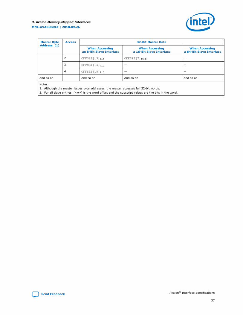
Master ByteAddress (1)
Access 32-Bit Master Data
When Accessing an 8-Bit Slave Interface
When Accessing a 16-Bit Slave Interface
When Accessing a 64-Bit Slave Interface
2 OFFSET[13]7..0 OFFSET[7]15..0 —
3 OFFSET[14]7..0 — —
4 OFFSET[15]7..0 — —
And so on And so on And so on And so on
Notes:1. Although the master issues byte addresses, the master accesses full 32-bit words.2. For all slave entries, [<n>] is the word offset and the subscript values are the bits in the word.
3. Avalon Memory-Mapped Interfaces
MNL-AVABUSREF | 2018.09.26
Send Feedback Avalon® Interface Specifications
37
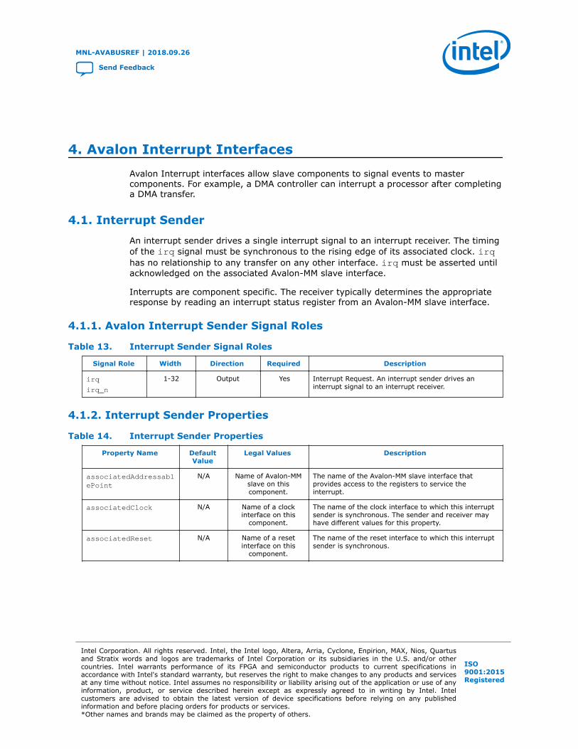
4. Avalon Interrupt InterfacesAvalon Interrupt interfaces allow slave components to signal events to mastercomponents. For example, a DMA controller can interrupt a processor after completinga DMA transfer.
4.1. Interrupt Sender
An interrupt sender drives a single interrupt signal to an interrupt receiver. The timingof the irq signal must be synchronous to the rising edge of its associated clock. irqhas no relationship to any transfer on any other interface. irq must be asserted untilacknowledged on the associated Avalon-MM slave interface.
Interrupts are component specific. The receiver typically determines the appropriateresponse by reading an interrupt status register from an Avalon-MM slave interface.
4.1.1. Avalon Interrupt Sender Signal Roles
Table 13. Interrupt Sender Signal Roles
Signal Role Width Direction Required Description
irq
irq_n
1-32 Output Yes Interrupt Request. An interrupt sender drives aninterrupt signal to an interrupt receiver.
4.1.2. Interrupt Sender Properties
Table 14. Interrupt Sender Properties
Property Name DefaultValue
Legal Values Description
associatedAddressablePoint
N/A Name of Avalon-MMslave on thiscomponent.
The name of the Avalon-MM slave interface thatprovides access to the registers to service theinterrupt.
associatedClock N/A Name of a clockinterface on this
component.
The name of the clock interface to which this interruptsender is synchronous. The sender and receiver mayhave different values for this property.
associatedReset N/A Name of a resetinterface on this
component.
The name of the reset interface to which this interruptsender is synchronous.
MNL-AVABUSREF | 2018.09.26
Send Feedback
Intel Corporation. All rights reserved. Intel, the Intel logo, Altera, Arria, Cyclone, Enpirion, MAX, Nios, Quartusand Stratix words and logos are trademarks of Intel Corporation or its subsidiaries in the U.S. and/or othercountries. Intel warrants performance of its FPGA and semiconductor products to current specifications inaccordance with Intel's standard warranty, but reserves the right to make changes to any products and servicesat any time without notice. Intel assumes no responsibility or liability arising out of the application or use of anyinformation, product, or service described herein except as expressly agreed to in writing by Intel. Intelcustomers are advised to obtain the latest version of device specifications before relying on any publishedinformation and before placing orders for products or services.*Other names and brands may be claimed as the property of others.
ISO9001:2015Registered

4.2. Interrupt Receiver
An interrupt receiver interface receives interrupts from interrupt sender interfaces.Components with Avalon-MM master interfaces can include an interrupt receiver todetect interrupts asserted by slave components with interrupt sender interfaces. Theinterrupt receiver accepts interrupt requests from each interrupt sender as a separatebit.
4.2.1. Avalon Interrupt Receiver Signal Roles
Table 15. Interrupt Receiver Signal Roles
Signal Role Width Direction Required Description
irq 1–32 Input Yes irq is an <n>-bit vector, where each bit correspondsdirectly to one IRQ sender with no inherent assumptionof priority.
4.2.2. Interrupt Receiver Properties
Table 16. Interrupt Receiver Properties
Property Name DefaultValue
LegalValues
Description
associatedAddressablePoint
N/A Name ofAvalon-MM
masterinterface
The name of the Avalon-MM master interface used toservice interrupts received on this interface.
associatedClock N/A Name of anAvalonClock
interface
The name of the Avalon Clock interface to which thisinterrupt receiver is synchronous. The sender andreceiver may have different values for this property.
associatedReset N/A Name of anAvalonReset
interface
The name of the reset interface to which this interruptreceiver is synchronous.
4.2.3. Interrupt Timing
The Avalon-MM master services the priority 0 interrupt before the priority 1 interrupt.
Figure 19. Interrupt TimingIn the following figure, interrupt 0 has higher priority. The interrupt receiver is in the process of handling int1when int0 is asserted. The int0 handler is called and completes. Then, the int1 handler resumes. Thediagram shows int0 deasserts at time 1. int1 deasserts at time 2.
clk
int0
int1
1 2
IndividualRequests
4. Avalon Interrupt Interfaces
MNL-AVABUSREF | 2018.09.26
Send Feedback Avalon® Interface Specifications
39

5. Avalon Streaming InterfacesYou can use Avalon Streaming (Avalon-ST) interfaces for components that drive highbandwidth, low latency, unidirectional data. Typical applications include multiplexedstreams, packets, and DSP data. The Avalon-ST interface signals can describetraditional streaming interfaces supporting a single stream of data without knowledgeof channels or packet boundaries. The interface can also support more complexprotocols capable of burst and packet transfers with packets interleaved acrossmultiple channels.
Figure 20. Avalon-ST Interface - Typical Application of the Avalon-ST Interface
SDRAMMemory
Avalon-MMMaster Interface
Processor
Avalon-MM Interface (Control Plane)
Avalon-MMMaster Interface
IO Control
Avalon-MMSlave Interface
SDRAM Cntl
Source Sink SinkSourcech 0-2
2
1
0
Scheduler
Tx IF CoreRx IF CoreAvalon-ST
InputAvalon-ST
Output
Avalon-ST Interfaces (Data Plane)
Intel FPGA
Printed Circuit Board
All Avalon-ST source and sink interfaces are not necessarily interoperable. However, iftwo interfaces provide compatible functions for the same application space, adaptersare available to allow them to interoperate.
MNL-AVABUSREF | 2018.09.26
Send Feedback
Intel Corporation. All rights reserved. Intel, the Intel logo, Altera, Arria, Cyclone, Enpirion, MAX, Nios, Quartusand Stratix words and logos are trademarks of Intel Corporation or its subsidiaries in the U.S. and/or othercountries. Intel warrants performance of its FPGA and semiconductor products to current specifications inaccordance with Intel's standard warranty, but reserves the right to make changes to any products and servicesat any time without notice. Intel assumes no responsibility or liability arising out of the application or use of anyinformation, product, or service described herein except as expressly agreed to in writing by Intel. Intelcustomers are advised to obtain the latest version of device specifications before relying on any publishedinformation and before placing orders for products or services.*Other names and brands may be claimed as the property of others.
ISO9001:2015Registered

Avalon-ST interfaces support datapaths requiring the following features:
• Low latency, high throughput point-to-point data transfer
• Multiple channel support with flexible packet interleaving
• Sideband signaling of channel, error, and start and end of packet delineation
• Support for data bursting
• Automatic interface adaptation
5.1. Terms and Concepts
The Avalon-ST interface protocol defines the following terms and concepts:
• Avalon Streaming System—An Avalon Streaming system contains one or moreAvalon-ST connections that transfer data from a source interface to a sinkinterface. The system shown above consists of Avalon-ST interfaces to transferdata from the system input to output. Avalon-MM control and status registerinterfaces provide for software control.
• Avalon Streaming Components—A typical system using Avalon-ST interfacescombines multiple functional modules, called components. The system designerconfigures the components and connects them together to implement a system.
• Source and Sink Interfaces and Connections—When two components connect, thedata flows from the source interface to the sink interface. The Avalon InterfaceSpecifications calls the combination of a source interface connecting to a sinkinterface a connection.
• Backpressure—Backpressure allows a sink to signal a source to stop sending data.Support for backpressure is optional. The sink uses backpressure to stop the flowof data for the following reasons:
— When the sink FIFOs are full
— When there is congestion on its output interface
• Transfers and Ready Cycles—A transfer results in data and control propagationfrom a source interface to a sink interface. For data interfaces, a ready cycle is acycle during which the sink can accept a transfer.
• Symbol—A symbol is the smallest unit of data. For most packet interfaces, asymbol is a byte. One or more symbols make up the single unit of data transferredin a cycle.
• Channel—A channel is a physical or logical path or link through which informationpasses between two ports.
• Beat—A beat is a single cycle transfer between a source and sink interface madeup of one or more symbols.
• Packet—A packet is an aggregation of data and control signals that a sourcetransmits simultaneously. A packet may contain a header to help routers and othernetwork devices direct the packet to the correct destination. The applicationdefines the packet format, not this specification. Avalon-ST packets can bevariable in length and can be interleaved across a connection. With an Avalon-STinterfaces, the use of packets is optional.
5. Avalon Streaming Interfaces
MNL-AVABUSREF | 2018.09.26
Send Feedback Avalon® Interface Specifications
41

5.2. Avalon Streaming Interface Signal Roles
Each signal in an Avalon-ST source or sink interface corresponds to one Avalon-STsignal role. An Avalon-ST interface may contain only one instance of each signal role.All Avalon-ST signal roles apply to both sources and sinks and have the same meaningfor both.
Table 17. Avalon-ST Interface SignalsIn the following table, all signal roles are active high.
Signal Role Width Direction Required Description
Fundamental Signals
channel 1 – 128 Source → Sink No The channel number for data being transferredon the current cycle.If an interface supports the channel signal, theinterface must also define the maxChannelparameter.
data 1 – 4,096 Source → Sink No The data signal from the source to the sink,typically carries the bulk of the information beingtransferred.Parameters further define the contents andformat of the data signal.
error 1 – 256 Source → Sink No A bit mask to mark errors affecting the databeing transferred in the current cycle. A single bitof the error signal masks each of the errors thecomponent recognizes. The errorDescriptordefines the error signal properties.
ready 1 Sink → Source No Asserts high to indicate that the sink can acceptdata. ready is asserted by the sink on cycle <n>to mark cycle <n + readyLatency> as a readycycle. The source may only assert valid andtransfer data during ready cycles.Sources without a ready input do not supportbackpressure. Sinks without a ready outputnever need to backpressure.
valid 1 Source → Sink No The source asserts this signal to qualify all othersource to sink signals. The sink samples data andother source-to-sink signals on ready cycleswhere valid is asserted. All other cycles areignored.Sources without a valid output implicitlyprovide valid data on every cycle that a sink isnot asserting backpressure. Sinks without avalid input expect valid data on every cyclethat they are not backpressuring.
Packet Transfer Signals
empty 1 – 5 Source → Sink No Indicates the number of symbols that are empty,that is, do not represent valid data. The emptysignal is not necessary on interfaces where thereis one symbol per beat.
endofpacket 1 Source → Sink No Asserted by the source to mark the end of apacket.
startofpacket 1 Source → Sink No Asserted by the source to mark the beginning ofa packet.
5. Avalon Streaming Interfaces
MNL-AVABUSREF | 2018.09.26
Avalon® Interface Specifications Send Feedback
42

5.3. Signal Sequencing and Timing
5.3.1. Synchronous Interface
All transfers of an Avalon-ST connection occur synchronous to the rising edge of theassociated clock signal. All outputs from a source interface to a sink interface,including the data, channel, and error signals, must be registered on the risingedge of clock. Inputs to a sink interface do not have to be registered. Registeringsignals at the source facilitates high frequency operation.
5.3.2. Clock Enables
Avalon-ST components typically do not include a clock enable input. The Avalon-STsignaling itself is sufficient to determine the cycles that a component should andshould not be enabled. Avalon-ST compliant components may have a clock enableinput for their internal logic. However, components using clock enables must ensurethat the timing of the interface adheres to the protocol.
5.4. Avalon-ST Interface Properties
Table 18. Avalon-ST Interface Properties
Property Name DefaultValue
LegalValues
Description
associatedClock 1 Clockinterface
The name of the Avalon Clock interface to which thisAvalon-ST interface is synchronous.
associatedReset 1 Resetinterface
The name of the Avalon Reset interface to which thisAvalon-ST interface is synchronous.
beatsPerCycle 1 1,2,4,8 Specifies the number of beats transferred in a singlecycle. This property allows you to transfer 2 separate,but correlated streams using the samestart_of_packet, end_of_packet, ready andvalid signals.beatsPerCycle is a rarely used feature of the Avalon-ST protocol.
dataBitsPerSymbol 8 1 – 512 Defines the number of bits per symbol. For example,byte-oriented interfaces have 8-bit symbols. This valueis not restricted to be a power of 2.
emptyWithinPacket false true, false When true, empty is valid for the entire packet.
errorDescriptor 0 List ofstrings
A list of words that describe the error associated witheach bit of the error signal. The length of the list mustbe the same as the number of bits in the error signal.The first word in the list applies to the highest orderbit. For example, “crc, overflow" means that bit[1]of error indicates a CRC error. Bit[0] indicates anoverflow error.
firstSymbolInHighOrderBits
true true, false When true, the first-order symbol is driven to the mostsignificant bits of the data interface. The highest-ordersymbol is labeled D0 in this specification. When thisproperty is set to false, the first symbol appears on thelow bits. D0 appears at data[7:0]. For a 32-bit bus, iftrue, D0 appears on bits[31:24].
maxChannel 0 0 – 255 Maximum number of channels that a data interface cansupport.
continued...
5. Avalon Streaming Interfaces
MNL-AVABUSREF | 2018.09.26
Send Feedback Avalon® Interface Specifications
43

Property Name DefaultValue
LegalValues
Description
readyLatency 0 0 – 8 Defines the relationship between the assertion of aready signal and the assertion of a valid signal. IfreadyLatency = <n> where n > 0, valid can beasserted only <n> cycles after assertion of ready.
readyAllowance(1) 0 0 – 8 Defines the number of transfers that the sink cancapture after ready is deasserted.When readyAllowance = 0, the sink cannot acceptany transfers after ready is deasserted. IfreadyAllowance = <n> where <n > 0>, the sinkcan accept up to <n> transfers after ready isdeasserted.
symbolsPerBeat 1 1 – 32 Number of symbols transferred on every valid cycle.
5.5. Typical Data Transfers
This section defines the transfer of data from a source interface to a sink interface. Inall cases, the data source and the data sink must comply with the specification. Thedata sink is not responsible for detecting source protocol errors.
5.6. Signal Details
The figure shows the signals that Avalon-ST interfaces typically includes. A typicalAvalon-ST source interface drives the valid, data, error, and channel signals tothe sink. The sink can apply backpressure with the ready signal.
Figure 21. Typical Avalon-ST Interface Signals
valid
data
error
ready
Data SinkData Source
channel<max_channel>
(1) • If readyLatency = 0 readyAllowance can be 0 or greater than 0.• If readyLatency > 0 readyAllowance must be equal to or greater than
readyLatency.• If the source or the sink do not specify a value for readyAllowance then
readyAllowance= readyLatency. Designs do not require the addition ofreadyAllowance unless you want the source or the sink to take advantage of this feature.
5. Avalon Streaming Interfaces
MNL-AVABUSREF | 2018.09.26
Avalon® Interface Specifications Send Feedback
44
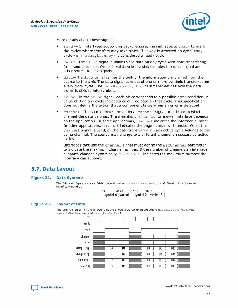
More details about these signals:
• ready—On interfaces supporting backpressure, the sink asserts ready to markthe cycles where transfers may take place. If ready is asserted on cycle <n>,cycle <n + readyLatency> is considered a ready cycle.
• valid—The valid signal qualifies valid data on any cycle with data transferringfrom source to sink. On each valid cycle the sink samples the data signal andother source to sink signals.
• data—The data signal carries the bulk of the information transferred from thesource to the sink. The data signal consists of one or more symbols transferred onevery clock cycle. The dataBitsPerSymbol parameter defines how the datasignal is divided into symbols.
• error—In the error signal, each bit corresponds to a possible error condition. Avalue of 0 on any cycle indicates error-free data on that cycle. This specificationdoes not define the action that a component takes when an error is detected.
• channel—The source drives the optional channel signal to indicate to whichchannel the data belongs. The meaning of channel for a given interface dependson the application. In some applications, channel indicates the interface number.In other applications, channel indicates the page number or timeslot. When thechannel signal is used, all the data transferred in each active cycle belongs to thesame channel. The source may change to a different channel on successive activecycles.
Interfaces that use the channel signal must define the maxChannel parameterto indicate the maximum channel number. If the number of channels an interfacesupports changes dynamically, maxChannel indicates the maximum number theinterface can support.
5.7. Data Layout
Figure 22. Data SymbolsThe following figure shows a 64-bit data signal with dataBitsPerSymbol=16. Symbol 0 is the mostsignificant symbol.
symbol 0 symbol 3symbol 2symbol 163 48 47 32 31 16 15 0
Figure 23. Layout of DataThe timing diagram in the following figure shows a 32-bit example where dataBitsPerSymbol=8,symbolsPerBeat=4, and beatsPerCycle=1.
clk
ready
valid
channel
error
data[31:24]
data[23:16]
data[15:8]
data[7:0]
D0 D4 D8
D1
D2
D3
D5
D6
D7
D9
DA
DD
DC
DE
DF
D11
D12
DB
D10
D13
5. Avalon Streaming Interfaces
MNL-AVABUSREF | 2018.09.26
Send Feedback Avalon® Interface Specifications
45

5.8. Data Transfer without Backpressure
The data transfer without backpressure is the most basic of Avalon-ST data transfers.On any given clock cycle, the source interface drives the data and the optionalchannel and error signals, and asserts valid. The sink interface samples thesesignals on the rising edge of the reference clock if valid is asserted.
Figure 24. Data Transfer without Backpressure
clkvalid
channel
error
data D1 D2 D3D0
5.9. Data Transfer with Backpressure
The sink asserts ready for a single clock cycle to indicate it is ready for an activecycle. If the sink is ready for data, the cycle is a ready cycle. During a ready cycle, thesource may assert valid and provide data to the sink. If the source has no data tosend, the source deasserts valid and can drive data to any value.
Interfaces that support backpressure define the readyLatency parameter to indicatethe number of cycles from the time that ready is asserted until valid data can bedriven. If the readyLatency is nonzero, cycle <n + readyLatency> is a readycycle if ready is asserted on cycle <n>.
When readyLatency = 0, data transfer only happens when ready and valid areasserted on the same cycle. In this mode, the source does not receive the sink’s readysignal before sending valid data. The source provides the data and asserts validwhenever the source has valid data. The source waits for the sink to capture the dataand assert ready. The source can change the data at any time. The sink onlycaptures input data from the source when ready and valid are both asserted.
When readyLatency >= 1, the sink asserts ready before the ready cycle itself.The source can respond during the appropriate cycle by asserting valid. The sourcemay not assert valid during cycles that are not ready cycles.
readyAllowance defines the number of transfers that the sink can capture whenready is deasserted. When readyAllowance = 0, the sink cannot accept anytransfers after ready is deasserted. If readyAllowance = <n> where n > 0, thesink can accept up to <n> transfers after ready is deasserted.
5.9.1. Data Transfers Using readyLatency and readyAllowance
5. Avalon Streaming Interfaces
MNL-AVABUSREF | 2018.09.26
Avalon® Interface Specifications Send Feedback
46

The following rules apply when transferring data with readyLatency andreadyAllowance.
• If readyLatency is 0, readyAllowance can be greater than or equal to 0.
• If readyLatency is greater than 0, readyAllowance can be greater than orequal to readyLatency.
When readyLatency = 0 and readyAllowance = 0, data transfers only whenboth ready and valid are asserted. In this case, the source does not receive thesink’s ready signal before sending valid data. The source provides the data andasserts valid whenever possible. The source waits for the sink to capture the dataand assert ready. The source can change the data at any time. The sink onlycaptures input data from the source when ready and valid are both asserted.
Figure 25. readyLatency = 0, readyAllowance = 0
When readyLatency = 0 and readyAllowance = 0 the source can assert valid at any time. The sinkcaptures the data from source only when ready = 1.
The following figure demonstrates these events:
1. In cycle 1 the source provides data and asserts valid.
2. In cycle 2, the sink asserts ready and D0 transfers.
3. In cycle 3, D1 transfers.
4. In cycle 4, the sink asserts ready, but the source does not drive valid data.
5. The source provides data and asserts valid on cycle 6.
6. In cycle 8, the sink asserts ready, so D2 transfers.
7. D3 transfers at cycle 9 and D4 transfers at cycle 10.
clk0
ready
valid
data
0 1 2 3 4 6 7 8 9 10 11 12 135
D2 D3 D4 D5D1D0
5. Avalon Streaming Interfaces
MNL-AVABUSREF | 2018.09.26
Send Feedback Avalon® Interface Specifications
47
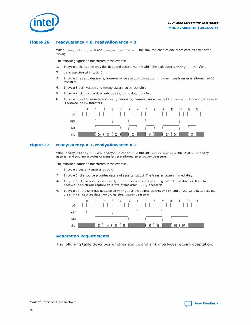
Figure 26. readyLatency = 0, readyAllowance = 1
When readyLatency = 0 and readyAllowance = 1 the sink can capture one more data transfer afterready = 0.
The following figure demonstrates these events:
1. In cycle 1 the source provides data and asserts valid while the sink asserts ready. D0 transfers.
2. D1 is transferred in cycle 2.
3. In cycle 3, ready deasserts, however since readyAllowance = 1 one more transfer is allowed, so D2transfers.
4. In cycle 5 both valid and ready assert, so D3 transfers.
5. In cycle 6, the source deasserts valid, so no data transfers.
6. In cycle 7, valid asserts and ready deasserts, however since readyAllowance = 1 one more transferis allowed, so D4 transfers.
clk0
ready
valid
data D0 D1 D2 D3 D4 D5 D6 D7
0 1 2 3 4 6 7 8 9 10 11 12 135
Figure 27. readyLatency = 1, readyAllowance = 2
When readyLatency = 1 and readyAllowance = 2 the sink can transfer data one cycle after readyasserts, and two more cycles of transfers are allowed after ready deasserts.
The following figure demonstrates these events:
1. In cycle 0 the sink asserts ready.
2. In cycle 1, the source provides data and asserts valid. The transfer occurs immediately.
3. In cycle 3, the sink deasserts ready, but the source is still asserting valid, and drives valid databecause the sink can capture data two cycles after ready deasserts.
4. In cycle 10, the sink has deasserted ready, but the source asserts valid and drives valid data becausethe sink can capture data two cycles after ready deasserts.
clk0
ready
valid
data D0 D1 D2 D3 D6 D7D4 D5
0 1 2 3 4 6 7 8 9 10 11 12 135
Adaptation Requirements
The following table describes whether source and sink interfaces require adaptation.
5. Avalon Streaming Interfaces
MNL-AVABUSREF | 2018.09.26
Avalon® Interface Specifications Send Feedback
48

Table 19. Source/Sink Adaptation Requirements
readyLatency readyAllowance Adaptation
Source readyLatency = SinkreadyLatency
Source readyAllowance =Sink readyAllowance
No adaptation required: The sink can capture alltransfers.
Source readyAllowance >Sink readyAllowance
Adaptation required: After ready is deasserted,the source can send more transfers than the sink cancapture.
Source readyAllowance <Sink readyAllowance
No adaptation required: After ready isdeasserted, the sink can capture more transfers thanthe source can send.
Source readyLatency > SinkreadyLatency
Source readyAllowance =Sink readyAllowance
No adaptation required: After ready is asserted,the source starts sending later than the sink cancapture. After ready is deasserted, the source cansend as many transfers as the sink can capture.
Source readyAllowance>Sink readyAllowance
Adaptation required: After ready is deasserted,the source can send more transfers than the sink cancapture.
Source readyAllowance<Sink readyAllowance
No adaptation required: After ready isdeasserted, the source sends fewer transfers thanthe sink can capture.
Source readyLatency <SinkreadyLatency
Source readyAllowance =Sink readyAllowance
Adaptation required: The source can start sendingtransfers before sink can capture.
Source readyAllowance>Sink readyAllowance
Adaptation required: The source can start sendingtransfers before the sink can capture. Also, afterready is deasserted, the source can send moretransfers than the sink can capture.
Source readyAllowance <Sink readyAllowance
Adaptation required: The source can start sendingtransfers before the sink can capture.
5.9.2. Data Transfers Using readyLatency
If the source or the sink do not specify a value for readyAllowance thenreadyAllowance= readyLatency. Designs that use source and sink do not requirethe addition of readyAllowance unless you want the source or the sink to takeadvantage of this feature.
5. Avalon Streaming Interfaces
MNL-AVABUSREF | 2018.09.26
Send Feedback Avalon® Interface Specifications
49
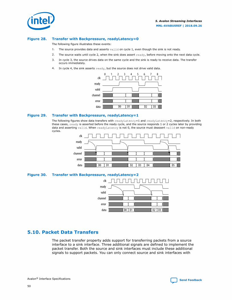
Figure 28. Transfer with Backpressure, readyLatency=0The following figure illustrates these events:
1. The source provides data and asserts valid on cycle 1, even though the sink is not ready.
2. The source waits until cycle 2, when the sink does assert ready, before moving onto the next data cycle.
3. In cycle 3, the source drives data on the same cycle and the sink is ready to receive data. The transferoccurs immediately.
4. In cycle 4, the sink asserts ready, but the source does not drive valid data.
clk
ready
valid
channel
error
data
0 1 2 3 5 6 7 84
D0 D1 D2 D3
Figure 29. Transfer with Backpressure, readyLatency=1The following figures show data transfers with readyLatency=1 and readyLatency=2, respectively. In boththese cases, ready is asserted before the ready cycle, and the source responds 1 or 2 cycles later by providingdata and asserting valid. When readyLatency is not 0, the source must deassert valid on non-readycycles.
clk
ready
valid
channel
error
data D0 D1 D2 D3 D4 D5
Figure 30. Transfer with Backpressure, readyLatency=2
clk
ready
valid
channel
error
data D0 D1 D2 D3
5.10. Packet Data Transfers
The packet transfer property adds support for transferring packets from a sourceinterface to a sink interface. Three additional signals are defined to implement thepacket transfer. Both the source and sink interfaces must include these additionalsignals to support packets. You can only connect source and sink interfaces with
5. Avalon Streaming Interfaces
MNL-AVABUSREF | 2018.09.26
Avalon® Interface Specifications Send Feedback
50

matching packet properties. Platform Designer does not automatically add thestartofpacket , endofpacket, and empty signals to source or sink interfaces thatdo not include these signals.
Figure 31. Avalon-ST Packet Interface Signals
channel<max channel>
valid
dataerror
ready
Data Source Data Sink
empty
startofpacketendofpacket
5.11. Signal Details
• startofpacket—All interfaces supporting packet transfers require thestartofpacket signal. startofpacket marks the active cycle containing thestart of the packet. This signal is only interpreted when valid is asserted.
• endofpacket—All interfaces supporting packet transfers require theendofpacket signal. endofpacket marks the active cycle containing the end ofthe packet. This signal is only interpreted when valid is asserted.startofpacket and endofpacket can be asserted in the same cycle. No idlecycles are required between packets. The startofpacket signal can followimmediately after the previous endofpacket signal.
• empty—The optional empty signal indicates the number of symbols that areempty during the endofpacket cycle. The sink only checks the value of theempty during active cycles that have endofpacket asserted. The empty symbolsare always the last symbols in data, those carried by the low-order bits whenfirstSymbolInHighOrderBits = true. The empty signal is required on allpacket interfaces whose data signal carries more than one symbol of data andhave a variable length packet format. The size of the empty signal in bits isceil[log2(<symbols per cycle>)].
5. Avalon Streaming Interfaces
MNL-AVABUSREF | 2018.09.26
Send Feedback Avalon® Interface Specifications
51
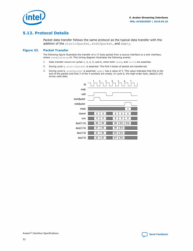
5.12. Protocol Details
Packet data transfer follows the same protocol as the typical data transfer with theaddition of the startofpacket, endofpacket, and empty.
Figure 32. Packet TransferThe following figure illustrates the transfer of a 17-byte packet from a source interface to a sink interface,where readyLatency=0. This timing diagram illustrates the following events:
1. Data transfer occurs on cycles 1, 2, 4, 5, and 6, when both ready and valid are asserted.
2. During cycle 1, startofpacket is asserted. The first 4 bytes of packet are transferred.
3. During cycle 6, endofpacket is asserted. empty has a value of 3. This value indicates that this is theend of the packet and that 3 of the 4 symbols are empty. In cycle 6, the high-order byte, data[31:24]drives valid data.
clk
ready
valid
startofpacket
endofpacket
empty
channel
error
data[31:24]
data[23:16]
data[15:8]
data[7:0]
0 0 0 0 0
0 0 0 0 0
D0 D4 D8 D12 D16
D1 D5 D9 D13
D2 D6 D10 D14
D3 D7 D11 D15
3
1 2 3 4 5 6 7
5. Avalon Streaming Interfaces
MNL-AVABUSREF | 2018.09.26
Avalon® Interface Specifications Send Feedback
52

6. Avalon Conduit InterfacesAvalon Conduit interfaces group an arbitrary collection of signals. You can specify anyrole for conduit signals. However, when you connect conduits, the roles and widthsmust match, and the directions must be opposite. An Avalon Conduit interface caninclude input, output, and bidirectional signals. A module can have multiple AvalonConduit interfaces to provide a logical signal grouping. Conduit interfaces can declarean associated clock. When connected conduit interfaces are in different clock domains,Platform Designer generates an error message.
Note: If possible, you should use the standard Avalon-MM or Avalon-ST interfaces instead ofcreating an Avalon Conduit interface. Platform Designer provides validation andadaptation for these interfaces. Platform Designer cannot provide validation oradaptation for Avalon Conduit interfaces.
Conduit interfaces typically used to drive off-chip device signals, such as an SDRAMaddress, data and control signals.
Figure 33. Focus on the Conduit Interface
Avalon-MM System
System Interconnect Fabric
EthernetPHY
AvalonSlave
Avalon-MMSlave
SDRAMMemory
Avalon-MMMaster
Processor
Avalon-MMMaster
Avalon-MMMaster
Ethernet MAC Custom Logic
SDRAMController
CustomLogic
ConduitInterface
CustomLogic
MNL-AVABUSREF | 2018.09.26
Send Feedback
Intel Corporation. All rights reserved. Intel, the Intel logo, Altera, Arria, Cyclone, Enpirion, MAX, Nios, Quartusand Stratix words and logos are trademarks of Intel Corporation or its subsidiaries in the U.S. and/or othercountries. Intel warrants performance of its FPGA and semiconductor products to current specifications inaccordance with Intel's standard warranty, but reserves the right to make changes to any products and servicesat any time without notice. Intel assumes no responsibility or liability arising out of the application or use of anyinformation, product, or service described herein except as expressly agreed to in writing by Intel. Intelcustomers are advised to obtain the latest version of device specifications before relying on any publishedinformation and before placing orders for products or services.*Other names and brands may be claimed as the property of others.
ISO9001:2015Registered

6.1. Avalon Conduit Signal Roles
Table 20. Conduit Signal Roles
Signal Role Width Direction Description
<any> <n> In, out, orbidirectional
A conduit interface consists of one or more input, output,or bidirectional signals of arbitrary width. Conduits canhave any user-specified role. You can connect compatibleConduit interfaces inside a Platform Designer (Standard)system provided the roles and widths match and thedirections are opposite.
6.2. Conduit Properties
There are no properties for conduit interfaces.
6. Avalon Conduit Interfaces
MNL-AVABUSREF | 2018.09.26
Avalon® Interface Specifications Send Feedback
54
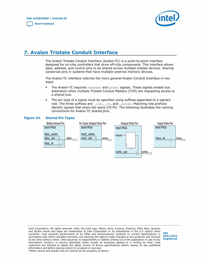
7. Avalon Tristate Conduit InterfaceThe Avalon Tristate Conduit Interface (Avalon-TC) is a point-to-point interfacedesigned for on-chip controllers that drive off-chip components. This interface allowsdata, address, and control pins to be shared across multiple tristate devices. Sharingconserves pins in systems that have multiple external memory devices.
The Avalon-TC interface restricts the more general Avalon Conduit Interface in twoways:
• The Avalon-TC requires request and grant signals. These signals enable busarbitration when multiple Tristate Conduit Masters (TCM) are requesting access toa shared bus.
• The pin type of a signal must be specified using suffixes appended to a signal’srole. The three suffixes are: _out, _in, and _outen. Matching role prefixesidentify signals that share the same I/O Pin. The following illustrates the namingconventions for Avalon-TC shared pins.
Figure 34. Shared Pin Types
data_out datadata_in
data_outen
Intel FPGABidirectional Pin
busy_in busy
Intel FPGAInput Only Pin
reset_out reset
Intel FPGATri-State Output Only Pin
reset_outen ~reset
Intel FPGAOutput Only Pin
write_out write
MNL-AVABUSREF | 2018.09.26
Send Feedback
Intel Corporation. All rights reserved. Intel, the Intel logo, Altera, Arria, Cyclone, Enpirion, MAX, Nios, Quartusand Stratix words and logos are trademarks of Intel Corporation or its subsidiaries in the U.S. and/or othercountries. Intel warrants performance of its FPGA and semiconductor products to current specifications inaccordance with Intel's standard warranty, but reserves the right to make changes to any products and servicesat any time without notice. Intel assumes no responsibility or liability arising out of the application or use of anyinformation, product, or service described herein except as expressly agreed to in writing by Intel. Intelcustomers are advised to obtain the latest version of device specifications before relying on any publishedinformation and before placing orders for products or services.*Other names and brands may be claimed as the property of others.
ISO9001:2015Registered

The next figure illustrates pin sharing using Avalon-TC interfaces. This figure illustratesthe following points.
• The Tristate Conduit Pin Sharer includes separate Tristate Conduit Slave Interfacesfor each Tristate Conduit Master. Each master and slave pair has its own requestand grant signals.
• The Tristate Conduit Pin Sharer identifies signals with identical roles as tristatesignals that share the same FPGA pin. In this example, the following signals areshared: addr_out, data_out, data_in, read_out, and write_out.
• The Tristate Conduit Pin Sharer drives a single bus including all the shared signalsto the Tristate Conduit Bridge. If the widths of shared signals differ, the TristateConduit Pin Sharer aligns them on their 0th bit. Tristate Conduit Pin Sharer drivesthe higher-order pins to 0 whenever the smaller signal has control of the bus.
• Signals that are not shared propagate directly through the Tristate Conduit PinSharer. In this example, the following signals are not shared: chipselect0_out,irq0_out, chipselect1_out, and irq1_out.
• All Avalon-TC interfaces connected to the same Tristate Conduit Pin Sharer mustbe in the same clock domain.
7. Avalon Tristate Conduit Interface
MNL-AVABUSREF | 2018.09.26
Avalon® Interface Specifications Send Feedback
56

Figure 35. Tristate Conduit InterfacesThe following illustrates the typical use of Avalon-TC Master and Slave interfaces and signal naming.
Intel FPGA
TCM
Tristate ConduitPin Sharer TCS
Tristate ConduitBridge
S
Controller for 2 MBytex32 SSRAM
CSIRQ
A[20:0]D_EN
D[31:0]DI[31:0]
RdWr
RequestGrant
TCM
S
GrantReq
A[22:0]D_EN
D[15:0]DI[15:0]
RdWr
TCM
chipselect_out
dataout_outendataout_out[31:0]
data_in[31:0]read_outwrite_out
requestgrant
requestgrant
addr_out_[20:0]
chipselect_outirq_in
Controller for 8 MByte
x16 Flash
addr_out<n>
data_out<n>
data_in<n>
data_outen<n>
chipselect_out
requestgrant
irq_inchipselect_out
write_out
read_out
clock
Avalon-MM Master
TCS
TCS
CSIRQ
Avalon-MM SlaveS
TCM Tristate Conduit Master
Tristate Conduit SlaveTCS
Arb
dataout_outendataout_out[15:0]
data_in[15:0]read_outwrite_out
addr_out_[22:0]
For more information about the Generic Tristate Controller and Tristate Conduit PinSharer, refer to the Avalon Tristate Conduit Components User Guide.
Related Information
Avalon Tristate Conduit Components User Guide
7.1. Avalon Tristate Conduit Signal Roles
The following table lists the signal defined for the Avalon Tristate Conduit interface. AllAvalon-TC signals apply to both masters and slaves and have the same meaning forboth
7. Avalon Tristate Conduit Interface
MNL-AVABUSREF | 2018.09.26
Send Feedback Avalon® Interface Specifications
57
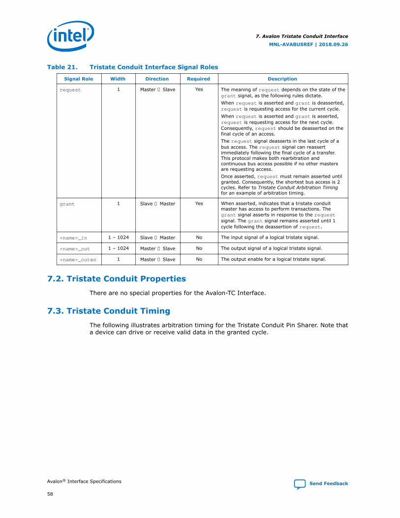
Table 21. Tristate Conduit Interface Signal Roles
Signal Role Width Direction Required Description
request 1 Master → Slave Yes The meaning of request depends on the state of thegrant signal, as the following rules dictate.When request is asserted and grant is deasserted,request is requesting access for the current cycle.When request is asserted and grant is asserted,request is requesting access for the next cycle.Consequently, request should be deasserted on thefinal cycle of an access.The request signal deasserts in the last cycle of abus access. The request signal can reassertimmediately following the final cycle of a transfer.This protocol makes both rearbitration andcontinuous bus access possible if no other mastersare requesting access.Once asserted, request must remain asserted untilgranted. Consequently, the shortest bus access is 2cycles. Refer to Tristate Conduit Arbitration Timingfor an example of arbitration timing.
grant 1 Slave → Master Yes When asserted, indicates that a tristate conduitmaster has access to perform transactions. Thegrant signal asserts in response to the requestsignal. The grant signal remains asserted until 1cycle following the deassertion of request.
<name>_in 1 – 1024 Slave → Master No The input signal of a logical tristate signal.
<name>_out 1 – 1024 Master → Slave No The output signal of a logical tristate signal.
<name>_outen 1 Master → Slave No The output enable for a logical tristate signal.
7.2. Tristate Conduit Properties
There are no special properties for the Avalon-TC Interface.
7.3. Tristate Conduit Timing
The following illustrates arbitration timing for the Tristate Conduit Pin Sharer. Note thata device can drive or receive valid data in the granted cycle.
7. Avalon Tristate Conduit Interface
MNL-AVABUSREF | 2018.09.26
Avalon® Interface Specifications Send Feedback
58
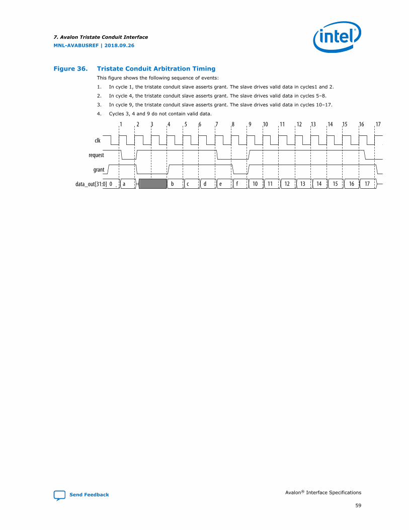
Figure 36. Tristate Conduit Arbitration TimingThis figure shows the following sequence of events:
1. In cycle 1, the tristate conduit slave asserts grant. The slave drives valid data in cycles1 and 2.
2. In cycle 4, the tristate conduit slave asserts grant. The slave drives valid data in cycles 5–8.
3. In cycle 9, the tristate conduit slave asserts grant. The slave drives valid data in cycles 10–17.
4. Cycles 3, 4 and 9 do not contain valid data.
clk
request
grant
data_out[31:0] 0 a b c d e f 10 11 12 13 14 15 16 17
1 3 62 74 5 8 10 139 1411 12 16 1715
.
7. Avalon Tristate Conduit Interface
MNL-AVABUSREF | 2018.09.26
Send Feedback Avalon® Interface Specifications
59
A. Deprecated SignalsDeprecated signals implement functionality that is no longer required or has beensuperseded.
begintransferAn output of Avalon-MM masters. Asserted for a single cycle at the beginning of atransfer. This is signal is not used and not necessary.
chipselect or chipselect_n
chipselect or chipselect_n: The chip select signal as described below wasdeprecated with the release of the Avalon Tristate Conduct (Avalon-TC) interface typewhich includes a chip select signal.
Formerly chipselect was a 1-bit input to an Avalon Memory-Mapped (Avalon-MM)slave interface signaling the beginning of a read or write transfer. The current PlatformDesigner interconnect filters read and write signals from masters according to theaddress and address map. The Platform Designer interconnect only drives read andwrite signals to the appropriate Avalon-MM slave, making a chip select unnecessary.
This signal dates from very early microprocessor designs. CPLDs decodedmicroprocessor addresses and generated chip selects for peripherals that werefrequently asynchronous. With synchronous systems this signal is unnecessary.
flush
Signal removed in version 1.2 of the Avalon Interface Specifications. Formerlyavailable to masters to clear pending transfers for pipelined reads.
MNL-AVABUSREF | 2018.09.26
Send Feedback
Intel Corporation. All rights reserved. Intel, the Intel logo, Altera, Arria, Cyclone, Enpirion, MAX, Nios, Quartusand Stratix words and logos are trademarks of Intel Corporation or its subsidiaries in the U.S. and/or othercountries. Intel warrants performance of its FPGA and semiconductor products to current specifications inaccordance with Intel's standard warranty, but reserves the right to make changes to any products and servicesat any time without notice. Intel assumes no responsibility or liability arising out of the application or use of anyinformation, product, or service described herein except as expressly agreed to in writing by Intel. Intelcustomers are advised to obtain the latest version of device specifications before relying on any publishedinformation and before placing orders for products or services.*Other names and brands may be claimed as the property of others.
ISO9001:2015Registered

B. Document Revision History for the Avalon InterfaceSpecifications
DocumentVersion
Intel Quartus PrimeVersion
Changes
2018.09.26 18.1 In the Write Bursts section, added a statement saying that writes withbyteenables being all 0's are passed on to the Avalon-MM slave as validtransactions.
2018.09.24 18.1 In Avalon Memory-Mapped Interface Signal Roles, added consecutivebyte-enable support.
2018.05.22 18.0 Made the following changes:• In the Avalon-ST Interface Properties table, corrected the default value
for beatsPerCycle. The default value is 1.• In the Avalon-ST Interface Properties table, added legal values for
beatsPerCycle. Legal values are 1, 2, 4, and 8.• Corrected minor errors and typos.
2018.05.07 18.0 Made the following changes:• Added support for the readyAllowance parameter.• Updated the Data Transfers with Backpressure topic to incorporate
support for the readyAllowance parameter.• Fixed minor errors and typos.
2018.03.22 17.1 Made the following changes:• Made the following changes to the Read and Write Transfers with
Waitrequest timing diagram— Removed readdatavalid signal which is not relevant when using
waitrequest
— Moved the number 4, readdata and response forward one cycle.— Aligned the read signal to number 1.
• Expanded the Transfers Using the waitrequestAllowance Propertysection. Provided more complex timing diagrams.
• Updated the discussion in the Read Bursts section. For reads with aburstcount > 1, Intel recommends asserting all byteenables.
• Enhanced discussion in the waitrequestAllowance Equals Two - NotRecommended topic. Corrected timing diagram. Data must be held for2 cycles starting at clock cycle 11.
November 2017 17.1 Made the following changes:
continued...
MNL-AVABUSREF | 2018.09.26
Send Feedback
Intel Corporation. All rights reserved. Intel, the Intel logo, Altera, Arria, Cyclone, Enpirion, MAX, Nios, Quartusand Stratix words and logos are trademarks of Intel Corporation or its subsidiaries in the U.S. and/or othercountries. Intel warrants performance of its FPGA and semiconductor products to current specifications inaccordance with Intel's standard warranty, but reserves the right to make changes to any products and servicesat any time without notice. Intel assumes no responsibility or liability arising out of the application or use of anyinformation, product, or service described herein except as expressly agreed to in writing by Intel. Intelcustomers are advised to obtain the latest version of device specifications before relying on any publishedinformation and before placing orders for products or services.*Other names and brands may be claimed as the property of others.
ISO9001:2015Registered
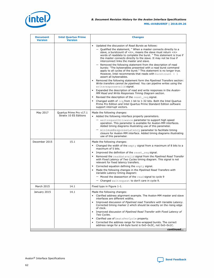
DocumentVersion
Intel Quartus PrimeVersion
Changes
• Updated the discussion of Read Bursts as follows:— Qualified the statement, " When a master connects directly to a
slave, a burstcount of <n>, means the slave must return <n>words of readdata to complete the burst. " This statement is true ifthe master connects directly to the slave. It may not be true ifinterconnect links the master and slave.
— Removed the following statement from the description of readbursts: "The byteenables presented with a read burst commandapply to all cycles of the burst." This statement is no longer true.However, Intel recommends that reads with burstcount > 1assert all byteenables.
• Removed the following statement form the Pipelined Transfers section:Write transfers cannot be pipelined. You can pipeline writes using thewriteresponsevalid signal.
• Expanded the description of read and write responses in the Avalon-MM Read and Write Responses Timing Diagram section.
• Revised the description of the reset_req signal.• Changed width of irq from 1 bit to 1-32 bits. Both the Intel Quartus
Prime Pro Edition and Intel Quartus Prime Standard Edition softwaresupport interrupt vectors.
May 2017 Quartus Prime Pro v17.1Stratix 10 ES Editions
Made the following changes:• Added the following interface property parameters.
— waitrequestAllowance parameter to support high speedoperation. This parameter is available for Avalon-MM interfaces.Added timing diagrams illustrating use of this parameter.
— minimumResponseLatency parameter to facilitate timingclosure for Avalon-MM interface. Added timing diagrams illustratinguse of this parameter.
December 2015 15.1 Made the following changes:• Changed the width of the empty signal from a maximum of 8 bits to a
maximum of 5 bits.• Improved the definition of the reset_req signal.• Removed the readdatavalid signal from the Pipelined Read Transfer
with Fixed Latency of Two Cycles timing diagram. This signal is notrelevant for fixed latency transfers.
• Corrected equation defining the empty signal.• Made the following changes in the Pipelined Read Transfers with
Variable Latency timing diagram:— Moved the deassertion of the read signal to cycle 9— Changed waitrequest to don't care in cycle 9.
March 2015 14.1 Fixed typo in Figure 1-1.
January 2015 14.1 Made the following changes:• Clarified address alignment example. The Avalon-MM master and slave
interfaces are different widths.• Improved discussion of Pipelined read Transfers with Variable Latency.
Corrected timing marker 2 which should be exactly on the rising edgeof clock.
• Improved discussion of Pipelined Read Transfer with Fixed Latency ofTwo Cycles.
• Clarified use of beatsPerCycle property.• Corrected the address range for line-wrapped bursts. The correct
address range for a 64-byte burst is 0x0–0x3C, not 0x0–0x1C.
continued...
B. Document Revision History for the Avalon Interface Specifications
MNL-AVABUSREF | 2018.09.26
Avalon® Interface Specifications Send Feedback
62
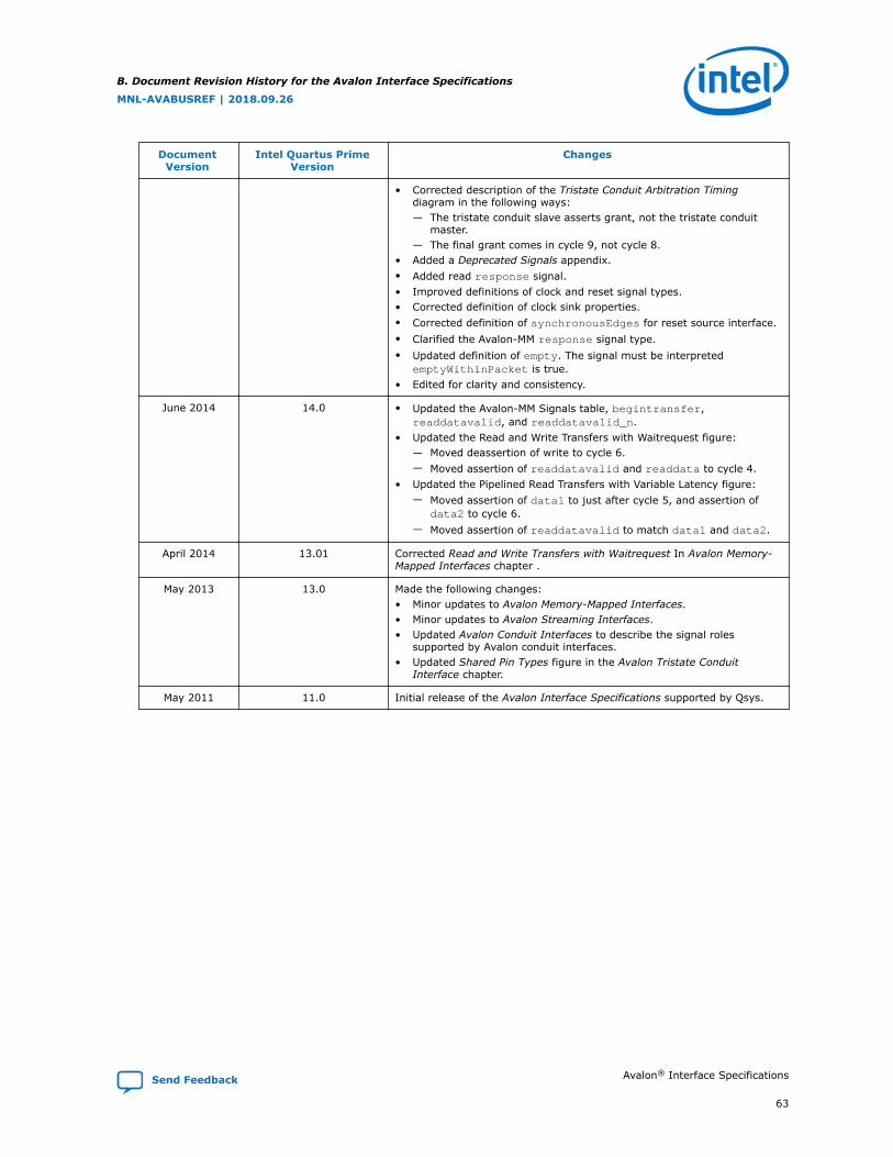
DocumentVersion
Intel Quartus PrimeVersion
Changes
• Corrected description of the Tristate Conduit Arbitration Timingdiagram in the following ways:— The tristate conduit slave asserts grant, not the tristate conduit
master.— The final grant comes in cycle 9, not cycle 8.
• Added a Deprecated Signals appendix.• Added read response signal.• Improved definitions of clock and reset signal types.• Corrected definition of clock sink properties.• Corrected definition of synchronousEdges for reset source interface.• Clarified the Avalon-MM response signal type.• Updated definition of empty. The signal must be interpreted
emptyWithinPacket is true.• Edited for clarity and consistency.
June 2014 14.0 • Updated the Avalon-MM Signals table, begintransfer,readdatavalid, and readdatavalid_n.
• Updated the Read and Write Transfers with Waitrequest figure:— Moved deassertion of write to cycle 6.— Moved assertion of readdatavalid and readdata to cycle 4.
• Updated the Pipelined Read Transfers with Variable Latency figure:— Moved assertion of data1 to just after cycle 5, and assertion of
data2 to cycle 6.— Moved assertion of readdatavalid to match data1 and data2.
April 2014 13.01 Corrected Read and Write Transfers with Waitrequest In Avalon Memory-Mapped Interfaces chapter .
May 2013 13.0 Made the following changes:• Minor updates to Avalon Memory-Mapped Interfaces.• Minor updates to Avalon Streaming Interfaces.• Updated Avalon Conduit Interfaces to describe the signal roles
supported by Avalon conduit interfaces.• Updated Shared Pin Types figure in the Avalon Tristate Conduit
Interface chapter.
May 2011 11.0 Initial release of the Avalon Interface Specifications supported by Qsys.
B. Document Revision History for the Avalon Interface Specifications
MNL-AVABUSREF | 2018.09.26
Send Feedback Avalon® Interface Specifications
63


