85
SpeedStream SpeedStream SpeedStream SpeedStream ® 4-Port DSL/Cable Router Model SS2604 Part No. 007-0113-001
| Date post: | 13-Mar-2015 |
| Category: |
Documents |
| Upload: | matthew-foxwell |
| View: | 73 times |
| Download: | 2 times |

SpeedStreamSpeedStreamSpeedStreamSpeedStream®
4-Port DSL/Cable RouterModel SS2604
Part No. 007-0113-001
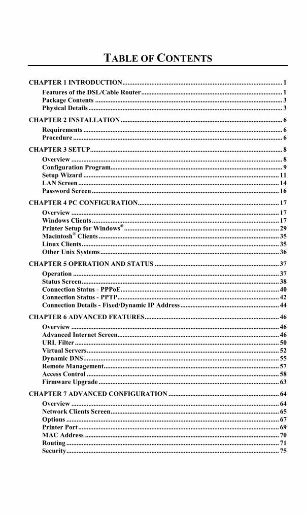
TABLE OF CONTENTS
CHAPTER 1 INTRODUCTION.............................................................................................. 1Features of the DSL/Cable Router................................................................................... 1Package Contents .............................................................................................................. 3Physical Details .................................................................................................................. 3
CHAPTER 2 INSTALLATION ............................................................................................... 6Requirements ..................................................................................................................... 6Procedure ........................................................................................................................... 6
CHAPTER 3 SETUP................................................................................................................. 8Overview ............................................................................................................................ 8Configuration Program..................................................................................................... 9Setup Wizard ................................................................................................................... 11LAN Screen ...................................................................................................................... 14Password Screen .............................................................................................................. 16
CHAPTER 4 PC CONFIGURATION................................................................................... 17Overview .......................................................................................................................... 17Windows Clients .............................................................................................................. 17Printer Setup for Windows®........................................................................................... 29Macintosh® Clients .......................................................................................................... 35Linux Clients.................................................................................................................... 35Other Unix Systems ......................................................................................................... 36
CHAPTER 5 OPERATION AND STATUS ......................................................................... 37Operation ......................................................................................................................... 37Status Screen.................................................................................................................... 38Connection Status - PPPoE............................................................................................. 40Connection Status - PPTP............................................................................................... 42Connection Details - Fixed/Dynamic IP Address .......................................................... 44
CHAPTER 6 ADVANCED FEATURES............................................................................... 46Overview .......................................................................................................................... 46Advanced Internet Screen............................................................................................... 46URL Filter ........................................................................................................................ 50Virtual Servers................................................................................................................. 52Dynamic DNS................................................................................................................... 55Remote Management....................................................................................................... 57Access Control ................................................................................................................. 58Firmware Upgrade .......................................................................................................... 63
CHAPTER 7 ADVANCED CONFIGURATION ................................................................. 64Overview .......................................................................................................................... 64Network Clients Screen................................................................................................... 65Options ............................................................................................................................. 67Printer Port ...................................................................................................................... 69MAC Address .................................................................................................................. 70Routing ............................................................................................................................. 71Security............................................................................................................................. 75

ii
APPENDIX A TROUBLESHOOTING ................................................................................ 77Overview .......................................................................................................................... 77General Problems ............................................................................................................ 77Internet Access................................................................................................................. 77Printing............................................................................................................................. 78
APPENDIX B SPECIFICATIONS........................................................................................ 81SpeedStream 4-Port DSL/Cable Router ........................................................................ 81
APPENDIX C TECHNICAL SUPPORT.............................................................................. 82
© 2002 Efficient Networks, Inc. A Siemens Company. All rights reserved. Efficient Networks,its logos and SpeedStream are registered and unregistered trademarks of Efficient Networks,Inc. Siemens and the Siemens logo are trademarks of Siemens AG, Germany. All other trade-marks are held by their respective companies. Efficient Networks reserves the right to makechanges to product specifications at any time without notice.
All trademarks and trade names are the properties of their respective owners.

1
Chapter 1
IntroductionThis Chapter provides an overview of the SpeedStream 4-Port DSL/CableRouter's features and capabilities.
Congratulations on the purchase of your new SpeedStream DSL/Cable Router, commonlyreferred to as a Broadband Router. The SpeedStream 4-Port DSL/Cable Router is a multi-function device providing the following services:• Shared Broadband Internet Access for all LAN users.• 4-Port Switching Hub for 10BaseT or 100BaseT connections.• Network Printer - LAN users can share the printer attached to the SpeedStream Router.
Figure 1: SpeedStream Router
Features of the DSL/Cable RouterThe SpeedStream 4-Port DSL/Cable Router incorporates many advanced features, carefullydesigned to provide sophisticated functions while being easy to use.
Internet Access Features• Shared Internet Access. All users on the LAN can access the Internet through the
DSL/Cable Router, using only a single external IP Address. The local (invalid) IP Ad-dresses are hidden from external sources. This process is called NAT (Network AddressTranslation).
• DSL & Cable Modem Support. The DSL/Cable Router has a 10BaseT Ethernet portfor connecting a DSL or Cable Modem. All popular DSL and Cable Modems are sup-ported.
• PPPoE and PPTP Support. The Internet (WAN port) connection supports PPPoE(PPP over Ethernet) and PPTP (Peer-to-Peer Tunneling Protocol), as well as "Direct Con-nection" type services.
1

DSL/Cable Router User Guide
2
• Fixed or Dynamic IP Address. On the Internet (WAN port) connection, theDSL/Cable Router supports both Dynamic IP Address (IP Address is allocated on connec-tion) and Fixed IP Address.
Advanced Internet Functions• Conferencing & Telephony Applications. Internet Telephony and Conferencing
applications, which are often difficult to use when behind a Firewall, are supported.• Special Internet Applications. Applications which use non-standard connections or
port numbers are normally blocked by the Firewall. The ability to define and allow suchapplications is provided, to enable such applications to be used normally.
• Virtual Servers. This feature allows Internet users to access Internet servers on yourLAN. The required setup is quick and easy.
• DMZ. One (1) PC on your local LAN can be configured to allow unrestricted 2-waycommunication with Servers or individual users on the Internet. This provides the ability torun programs that are incompatible with Firewalls.
• URL Filter. Use the URL Filter to block access to undesirable Web sites by LAN users.• Internet Access Log. See which Internet connections have been made.• VPN Support. VPN (Virtual Private Networking) connections using PPTP and IPSec are
transparently supported - no configuration is required.
LAN Features• 4-Port Switching Hub. The DSL/Cable Router incorporates a 4-port 10/100BaseT
switching hub, making it easy to create or extend your LAN.• DHCP Server Support. Dynamic Host Configuration Protocol provides a dynamic IP
address to PCs and other devices upon request. The DSL/Cable Router can act as a DHCPServer for devices on your local LAN and WLAN.
• Multi Segment LAN Support. LANs containing one or more segments are supported,via the Router's RIP (Routing Information Protocol) support and built-in static routing ta-ble.
• Network Printer. The printer attached to the DSL/Cable Router becomes a "NetworkPrinter", available to all Windows and Linux (Unix) clients on your LAN.
Configuration & Management• Easy Setup. Use your WEB browser from anywhere on the LAN for configuration.• Remote Management. The DSL/Cable Router can be managed from any PC on your
LAN. And, if the Internet connection exists, it can also (optionally) be configured via theInternet.
• UPnP Support. UPnP (Universal Plug and Play) allows automatic discovery and con-figuration of the DSL/Cable Router. UPnP is by supported by Windows ME, XP, or later.

Introduction
3
Security Features• Password - protected Configuration. Optional password protection is provided to
prevent unauthorized users from modifying the configuration data and settings.• NAT Protection. An intrinsic side effect of NAT (Network Address Translation) tech-
nology is that by allowing all LAN users to share a single IP address, the location and eventhe existence of each PC is hidden. From the external viewpoint, there is no network, onlya single device - the DSL/Cable Router.
• Stateful Inspection Firewall. All incoming data packets are monitored and all incom-ing server requests are filtered, thus protecting your network from malicious attacks fromexternal sources.
• Protection against DoS attacks. DoS (Denial of Service) attacks can flood yourInternet connection with invalid packets and connection requests, using so much bandwidthand so many resources that Internet access becomes unavailable. The DSL/Cable Routerincorporates protection against DoS attacks.
Package ContentsThe following items should be included:• SpeedStream 4-Port DSL/Cable Router (SS2604)• Power Adapter• Quick Start Guide• CD-ROM containing the on-line manual and Print Port Driver for Windows®
• Extended Warranty/Product Registration Card
If any of the above items are damaged or missing, please contact SpeedStream TechnicalSupport for assistance.
Physical Details
LEDs
The front panel contains the following LEDs.
Power On - Normal operation.
Off - No power
Status On - Error condition.
Off - Normal operation.
Blinking - This LED blinks during start up, or when the Firmware is beingupgraded.

DSL/Cable Router User Guide
4
LAN Ports
(1, 2, 3, 4)
For each LAN port, there are 2 LEDs
• Link/Act• On - Corresponding LAN (hub) port is active.• Off - No active connection on the corresponding LAN (hub) port.• Flashing - Data is being transmitted or received via the corre-
sponding LAN (hub) port.• 100
• On - Corresponding LAN (hub) port is using 100BaseT.• Off - Corresponding LAN (hub) port connection is using
10BaseT, or no active connection.
WAN Port Flashing - data is being transmitted or received via the WAN port.
Off - no data is being transferred.
Print Act On - Connection to printer established.
Off - No connection to printer; printer is Off or Off-line.
Flashing - Data is being transmitted to the printer.
Print Err On - Printer error detected.
Off - No printer error detected.
Rear Panel
Figure 2: Rear Panel
Printer Port Standard parallel printer port. If you wish to share a printer, connectit here.
Reset Button This button has three (3) functions:• Reboot. When pressed and released, the DSL/Cable Router
will reboot (restart).• Diagnostic print-out. If held down for 3 seconds, a diagnostic
print-out will be sent to the attached printer.• Ensure the printer is ready.• Both Print LEDs will flash simultaneously during the di-
agnostic printing.• Restore Factory Defaults. This button can also be used to
clear ALL data and restore ALL settings to the factory defaultvalues.
To Clear All Data and restore the factory default values:1. Power Off the router.

Introduction
5
2. Hold the Reset Button down while you Power On the router.3. Continue holding the Reset Button until the Status (Red) LED
blinks TWICE.4. Release the Reset Button.
The factory default configuration has now been restored, andthe Router is ready for use.
WAN port(10BaseT)
Connect the DSL or Cable Modem here. If your modem came witha cable, use the supplied cable. Otherwise, use a standard LANcable.
10/100BaseTLAN connectors
Use standard LAN cables (RJ45 connectors) to connect this port toyour PCs. Both 10BaseT and 100BaseT connections can be usedsimultaneously.
LAN1 can act either as a normal port, or an "Uplink" port forconnection to another Hub. See the "Normal/Uplink" buttonbelow.
Normal/UplinkButton- Optional
If this button is present, it allows LAN port 1 to be used as anUplink port for connecting directly to another hub.
When depressed (in), then the "LAN 1" port becomes an "Uplink"port, and must be connected to a normal port on another Hub.
If this button is extended (out), then the "LAN 1" port acts as anormal LAN port.
Power port Connect the supplied power adapter here.

6
Chapter 2
InstallationThis Chapter covers the physical installation of the SpeedStream DSL/CableRouter.
Requirements• DSL or Cable modem, and an Internet Access account with an ISP, for shared Internet
access.• Network cables. Use standard 10/100BaseT CAT5 network (UTP) cables with RJ45
connectors• TCP/IP network protocol must be installed on all PCs.• For shared access to the attached printer, the following clients are supported:
• Windows 95/98/ME• Windows NT 4.0, 2000 or XP• Unix (LPD printing)
Procedure
Figure 3: Installation Diagram
1. Choose an Installation SiteSelect a suitable place on the network to install the DSL/Cable Router.Ensure that both the DSL/Cable Router and the DSL or Cable modem are powered OFF.
2. Connect LAN Cables• Use standard 10/100 CAT5 network cables to connect PCs to the Switching Hub ports on
the DSL/Cable Router.• Both 10BaseT and 100BaseT connections can be used simultaneously.
2

Installation
7
3. Connect WAN CableConnect the DSL or Cable modem to the WAN port on the DSL/Cable Router. Use the ca-ble supplied with your DSL/Cable modem. .
4. Connect Printer CableUse a standard parallel printer cable to connect your printer to the Printer port on theDSL/Cable Router.
5. Power Up• Power on the Cable or DSL modem.• Power on the Printer.• Connect the supplied power adapter to the DSL/Cable Router and power up the router.
Use only the power adapter provided. Using a different one may cause hardware damage
6. Check the LEDs• The Status LED should flash, then turn On. If it stays On, or flashing, there is a hardware
error.• For each active LAN (PC) connection, the LAN Link/Act LED should be ON• The WAN LED should be ON.• The Print Act LED should be ON.
For more information, refer to LEDs in Chapter 1.

8
Chapter 3
SetupThis Chapter provides details of the Setup process.
OverviewThis chapter describes the setup procedure for:• Internet Access• LAN configuration• Assigning a Password to protect the configuration data.
PCs on your local LAN may also require configuration. For details, see Chapter 4 - PC Con-figuration.
Other configuration may also be required, depending on which features and functions of theDSL/Cable Router you wish to use. Use the table below to locate detailed instructions for therequired functions.
To Do this: Refer to:
Configure PCs on your LAN. Chapter 4:PC Configuration
Check DSL/Cable Router's operation and Status. Chapter 5:Operation and Status
Use any of the following Internet features:• Special Applications• DMZ• Virtual Servers• Dynamic DNS• Remote Management
Chapter 6:Advanced Features
Use any of the following Advanced Configuration settings:• Network Clients• Options (Backup DNS, TFTP, UPnP)• Security and Firewall settings• Printer Port setup (for Linux/Unix only)• Routing (RIP and static Routing)• Firmware Upgrade
Chapter 7Advanced Configuration
Where use of a certain feature requires thatPCs or other LAN devices be configured, thisis also explained in the relevant chapter.
3
Setup
9
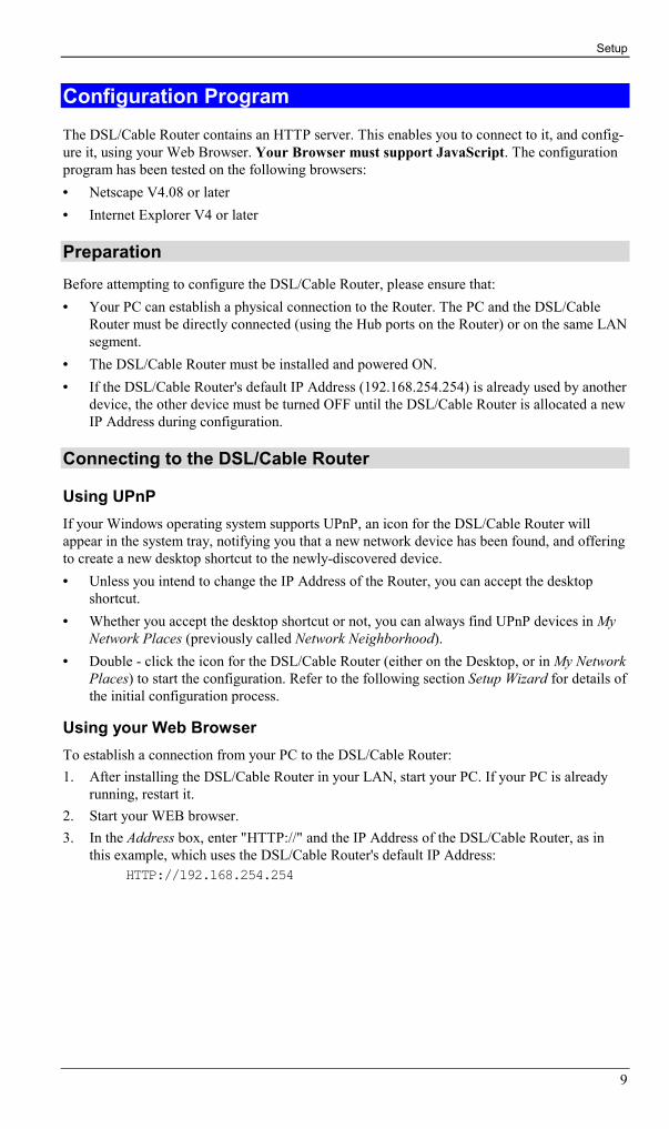
Configuration ProgramThe DSL/Cable Router contains an HTTP server. This enables you to connect to it, and config-ure it, using your Web Browser. Your Browser must support JavaScript. The configurationprogram has been tested on the following browsers:• Netscape V4.08 or later• Internet Explorer V4 or later
PreparationBefore attempting to configure the DSL/Cable Router, please ensure that:• Your PC can establish a physical connection to the Router. The PC and the DSL/Cable
Router must be directly connected (using the Hub ports on the Router) or on the same LANsegment.
• The DSL/Cable Router must be installed and powered ON.• If the DSL/Cable Router's default IP Address (192.168.254.254) is already used by another
device, the other device must be turned OFF until the DSL/Cable Router is allocated a newIP Address during configuration.
Connecting to the DSL/Cable Router
Using UPnPIf your Windows operating system supports UPnP, an icon for the DSL/Cable Router willappear in the system tray, notifying you that a new network device has been found, and offeringto create a new desktop shortcut to the newly-discovered device.• Unless you intend to change the IP Address of the Router, you can accept the desktop
shortcut.• Whether you accept the desktop shortcut or not, you can always find UPnP devices in My
Network Places (previously called Network Neighborhood).• Double - click the icon for the DSL/Cable Router (either on the Desktop, or in My Network
Places) to start the configuration. Refer to the following section Setup Wizard for details ofthe initial configuration process.
Using your Web BrowserTo establish a connection from your PC to the DSL/Cable Router:1. After installing the DSL/Cable Router in your LAN, start your PC. If your PC is already
running, restart it.2. Start your WEB browser.3. In the Address box, enter "HTTP://" and the IP Address of the DSL/Cable Router, as in
this example, which uses the DSL/Cable Router's default IP Address:HTTP://192.168.254.254

DSL/Cable Router User Guide
10
If you can't connectIf the Router does not respond, check the following:• The DSL/Cable Router is properly installed, LAN connection is OK, and it is
powered ON. You can test the connection by using the "Ping" command:• Open the MS-DOS window or command prompt window.• Enter the command:
ping 192.168.254.254If no response is received, either the connection is not working, or yourPC's IP address is not compatible with the DSL/Cable Router's IP Address.(See next item.)
• If your PC is using a fixed IP Address, its IP Address must be within the range192.168.254.1 to 192.168.254.253 to be compatible with the DSL/CableRouter's default IP Address of 192.168.254.254. Also, the Network Mask mustbe set to 255.255.255.0. See Chapter 4 - PC Configuration for details onchecking your PC's TCP/IP settings.
• Ensure that your PC and the DSL/Cable Router are on the same networksegment. (If you don't have a router, this must be the case.)

Setup
11
Setup WizardThe first time you connect to the DSL/Cable Router, the Setup Wizard will run automatically.(The Setup Wizard will also run if the Router's default settings are restored.)
1. Step through the Wizard until finished.• You need to know the type of Internet connection service used by your ISP. Check the
data supplied by your ISP.• The common connection types and associated data are explained in the tables below.
2. On the final screen of the Wizard, run the test and check that an Internet connection can beestablished.• If the connection fails, check your data, the Cable or DSL modem, and all connec-
tions.• When you exit the Wizard, you will see the Home screen. If you wish to run the Wiz-
ard again at any time, use the "Setup Wizard" button on the main menu.
Cable ModemsData Details Check
Hostname Some ISPs allocate a "Host-name".
If so, you must enter this"Hostname" instead of usingthe default value.
Did your ISP allocate a "Host-name" to you?
If so, enter the name provided.
Otherwise, use the default value.
Domain name Some ISPs allocate a "Do-main Name".
If so, you must enter this"Domain Name" instead ofusing the default value.
Did your ISP allocate a "DomainName" to you?
If so, enter the name provided.
Otherwise, use the default value.
MAC address Some ISPs record the MAC(physical) address of yourPC, and will only permitconnections from thataddress.
Does your ISP expect a particularMAC address?
If YES, enter the value (ifknown), or use the "Clone MACaddress" button to copy your PCsaddress to the DSL/Cable Router.
If NO, use the default MACaddress.
IP Address There are 2 systems used:• Dynamic -Your IP
Address is allocatedautomatically, whenyour connect to you ISP.
• Static - Your ISPallocates a permanent IPAddress to you.
Were you allocated a specified IPAddress ?
If YES, select "Fixed IP address"in the Wizard, and enter thedetails provided by your ISP.
If NO, select "Dynamic IP ad-dress" in the Wizard.
DSL/Cable Router User Guide
12
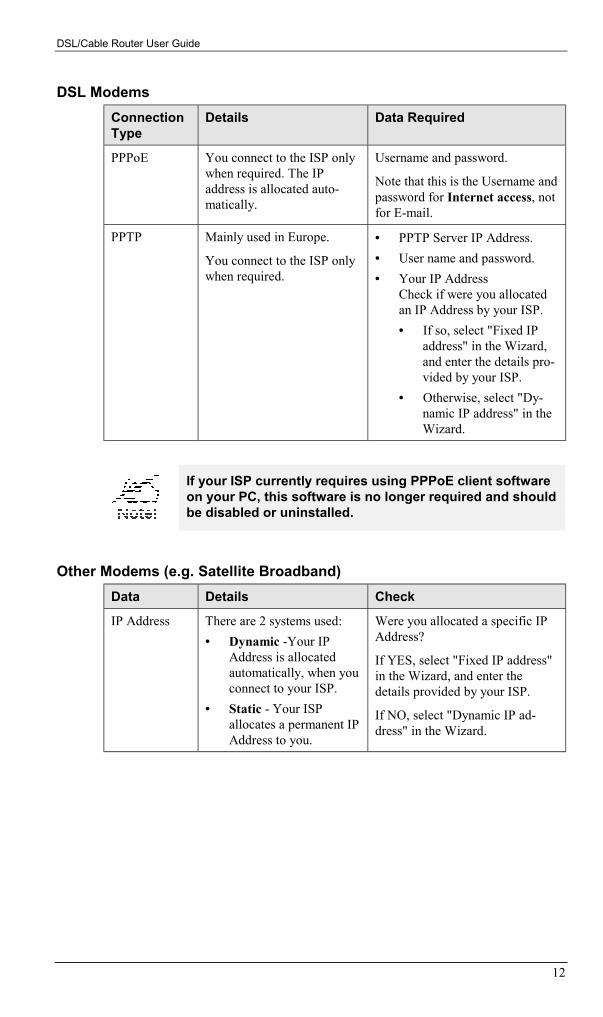
DSL ModemsConnectionType
Details Data Required
PPPoE You connect to the ISP onlywhen required. The IPaddress is allocated auto-matically.
Username and password.
Note that this is the Username andpassword for Internet access, notfor E-mail.
PPTP Mainly used in Europe.
You connect to the ISP onlywhen required.
• PPTP Server IP Address.• User name and password.• Your IP Address
Check if were you allocatedan IP Address by your ISP.• If so, select "Fixed IP
address" in the Wizard,and enter the details pro-vided by your ISP.
• Otherwise, select "Dy-namic IP address" in theWizard.
If your ISP currently requires using PPPoE client softwareon your PC, this software is no longer required and shouldbe disabled or uninstalled.
Other Modems (e.g. Satellite Broadband)Data Details Check
IP Address There are 2 systems used:• Dynamic -Your IP
Address is allocatedautomatically, when youconnect to your ISP.
• Static - Your ISPallocates a permanent IPAddress to you.
Were you allocated a specific IPAddress?
If YES, select "Fixed IP address"in the Wizard, and enter thedetails provided by your ISP.
If NO, select "Dynamic IP ad-dress" in the Wizard.

Setup
13
Home ScreenAfter finishing the Setup Wizard, you will see the Home screen. When you connect in thefuture, you will see this screen when you connect. An example screen is shown below.
Figure 4: Home Screen
Navigation & Data Input• Use the menu bar on the left of the screen, and the "Back" button on your Browser, for
navigation.• Changing to another screen without clicking "Save" does NOT save any changes you may
have made. You must "Save" before changing screens or your data will be ignored.• When finished, you should use the "Logout" button, rather than just close your Browser.
On each screen, clicking the "Help" button willdisplay help for that screen.
From any help screen, you can access the list of allhelp files (help index).

DSL/Cable Router User Guide
14
LAN ScreenUse the LAN link on the main menu to reach the LAN screen An example screen is shownbelow.
Figure 5: LAN Screen
Data - LAN ScreenTCP/IP
IP Address IP address for the DSL/Cable Router, as seen from the local LAN. Usethe default value unless the address is already in use or your LAN isusing a different IP address range. In the latter case, enter an unused IPAddress from within the range used by your LAN.
Subnet Mask The default value 255.255.255.0 is standard for small (class "C")networks. For other networks, use the Subnet Mask for the LANsegment to which the DSL/Cable Router is attached (the same value asthe PCs on that LAN segment).
DHCP Server • If Enabled, the DSL/Cable Router will allocate IP Addresses toPCs (DHCP clients) on your LAN when they start up. The default(and recommended) value is Enabled.
• If you are already using a DHCP Server, this setting must beDisabled, and the existing DHCP server must be re-configured totreat the DSL/Cable Router as the Gateway. See the following sec-tion for further details.
• The Start IP Address and Finish IP Address fields set the valuesused by the DHCP server when allocating IP Addresses to DHCPclients. This range also determines the number of DHCP clientssupported.
See the following section for further details on using DHCP.
Buttons
Save Save the data on screen.
Cancel The "Cancel" button will discard any data you have entered and reloadthe file from the DSL/Cable Router.

Setup
15
DHCP
What DHCP DoesA DHCP (Dynamic Host Configuration Protocol) server allocates a valid IP address to aDHCP client (PC or device) upon request.• The client request is made when the client device starts up (boots).• The DHCP Server provides the Gateway and DNS addresses to the client, as well as
allocating an IP Address.• The DSL/Cable Router can act as a DHCP server.• Windows 95/98/Me and other non-Server versions of Windows will act as a DHCP client.
This is the default Windows setting for the TCP/IP network protocol. However, Windowsuses the term Obtain an IP Address automatically instead of "DHCP Client".
• You must NOT have two (2) or more DHCP Servers on the same LAN segment. (If yourLAN does not have other Routers, this means there must only be one (1) DHCP Server onyour LAN.)
Using the DSL/Cable Router's DHCP ServerThis is the default setting. The DHCP Server settings are on the LAN screen. On this screen,you can:• Enable or Disable the DSL/Cable Router's DHCP Server function.• Set the range of IP Addresses allocated to PCs by the DHCP Server function.
You can assign Fixed IP Addresses to some deviceswhile using DHCP, provided that the Fixed IP Addressesare NOT within the range used by the DHCP Server.
Using another DHCP ServerYou can only use one (1) DHCP Server per LAN segment. If you wish to use another DHCPServer, rather than the DSL/Cable Router's, the following procedure is required.1. Disable the DHCP Server feature in the DSL/Cable Router. This setting is on the LAN
screen.2. Configure the DHCP Server to provide the DSL/Cable Router's IP Address as the Default
Gateway.
To Configure your PCs to use DHCPThis is the default setting for TCP/IP under Windows 95/98/Me See Chapter 4 - Client Con-figuration for the procedure to check these settings.

DSL/Cable Router User Guide
16
Password ScreenThe password screen allows you to assign a password to the DSL/Cable Router.
Figure 6: Password Screen
Once you have assigned a password to the DSL/Cable Router (on the Password screen above)you will be prompted for the password when you connect, as shown below. (If no password hasbeen set, this dialog will not appear.)
Figure 7: Password Dialog
• Leave the "User Name" blank.• Enter the password for the DSL/Cable Router, as set on the Password screen above.

17
Chapter 4
PC ConfigurationThis Chapter details the PC Configuration required on the local ("Internal")LAN.
OverviewFor each PC, the following may to be configured:• TCP/IP network settings• Internet Access configuration• Printer configuration
Windows ClientsThis section describes how to configure Windows clients for:• Internet access via the DSL/Cable Router• Sharing the Printer connected to the DSL/Cable Router.
The first step is to check the PC's TCP/IP settings.
The DSL/Cable Router uses the TCP/IP network protocol for all functions, so it is essential thatthe TCP/IP protocol be installed and configured on each PC.
TCP/IP Settings - Overview
If using the default DSL/Cable Router settings, and the default WindowsTCP/IP settings, no changes need to be made.
• By default, the DSL/Cable Router will act as a DHCP Server, automatically providing asuitable IP Address (and related information) to each PC when the PC boots.
• For all non-Server versions of Windows, the default TCP/IP setting is to act as a DHCPclient.
If using a Fixed (specified) IP address, the following changes are re-quired:• The Gateway must be set to the IP address of the DSL/Cable Router• The DNS should be set to the address provided by your ISP.
If your LAN has a Router, the LAN Administrator must re-configure the Router itself. Refer to Chapter 7 - Routingfor details.
4

DSL/Cable Router User Guide
18
Checking TCP/IP Settings - Windows 9x/Me1. Select Control Panel - Network. You should see a screen like the following:
Figure 8: Network Configuration
2. Select the TCP/IP protocol for your network card.3. Click on the Properties button. You should then see a screen like the following.
Figure 9: IP Address (Win 95)
Ensure your TCP/IP settings are correct, as follows:
Using DHCPTo use DHCP, select the radio button Obtain an IP Address automatically. This is the defaultWindows settings.
Restart your PC to ensure it obtains an IP Address from the DSL/Cable Router.
Using "Specify an IP Address"• If your PC is already configured, do NOT change the settings on the IP Address tab shown
in Figure 9 above.

PC Configuration
19
• On the Gateway tab, enter the DSL/Cable Router's IP address in the New Gateway fieldand click Add. Your LAN administrator can advise you of the IP Address they assigned tothe DSL/Cable Router.
Figure 10: Gateway Tab (Win 95/98)
• On the DNS Configuration tab, ensure Enable DNS is selected. If the DNS Server SearchOrder list is empty, enter the DNS address provided by your ISP in the fields beside theAdd button, then click Add.
Figure 11: DNS Tab (Win 95/98)

DSL/Cable Router User Guide
20
Checking TCP/IP Settings - Windows NT4.01. Select Control Panel - Network, and, on the Protocols tab, select the TCP/IP protocol, as
shown below.
Figure 12: Windows NT4.0 - TCP/IP
2. Click the Properties button to see a screen like the one below.

PC Configuration
21
Figure 13: Windows NT4.0 - IP Address
3. Select the network card for your LAN.4. Select the appropriate radio button - Obtain an IP address from a DHCP Server or Specify
an IP Address, as explained below.
Obtain an IP address from a DHCP ServerThis is the default Windows setting. Using this is recommended. By default, the DSL/CableRouter will act as a DHCP Server.
Restart your PC to ensure it obtains an IP Address from the DSL/Cable Router.
Specify an IP AddressIf your PC is already configured, check with your network administrator before making thefollowing changes.
1. The Default Gateway must be set to the IP address of the DSL/Cable Router. To set this:• Click the Advanced button on the screen above.• On the following screen, click the Add button in the Gateways panel, and enter the
DSL/Cable Router's IP address, as shown in Figure 14 below.• If necessary, use the Up button to make the DSL/Cable Router the first entry in the
Gateways list.

DSL/Cable Router User Guide
22
Figure 14 - Windows NT4.0 - Add Gateway
2. The DNS should be set to the address provided by your ISP, as follows:• Click the DNS tab.• On the DNS screen, shown below, click the Add button (under DNS Service Search
Order), and enter the DNS provided by your ISP.

PC Configuration
23
Figure 15: Windows NT4.0 - DNS

DSL/Cable Router User Guide
24
Checking TCP/IP Settings - Windows 2000:1. Select Control Panel - Network and Dial-up Connection.2. Right click the Local Area Connection icon and select Properties. You should see a screen
like the following:
Figure 16: Network Configuration (Win 2000)
3. Select the TCP/IP protocol for your network card.4. Click on the Properties button. You should then see a screen like the following.
PC Configuration
25
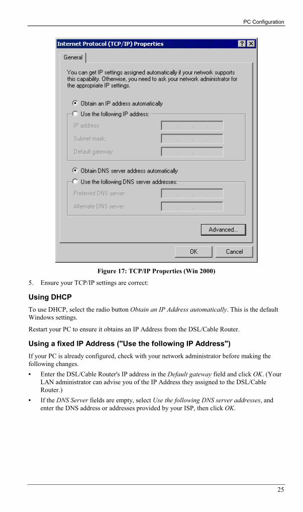
Figure 17: TCP/IP Properties (Win 2000)
5. Ensure your TCP/IP settings are correct:
Using DHCPTo use DHCP, select the radio button Obtain an IP Address automatically. This is the defaultWindows settings.
Restart your PC to ensure it obtains an IP Address from the DSL/Cable Router.
Using a fixed IP Address ("Use the following IP Address")If your PC is already configured, check with your network administrator before making thefollowing changes.• Enter the DSL/Cable Router's IP address in the Default gateway field and click OK. (Your
LAN administrator can advise you of the IP Address they assigned to the DSL/CableRouter.)
• If the DNS Server fields are empty, select Use the following DNS server addresses, andenter the DNS address or addresses provided by your ISP, then click OK.
DSL/Cable Router User Guide
26
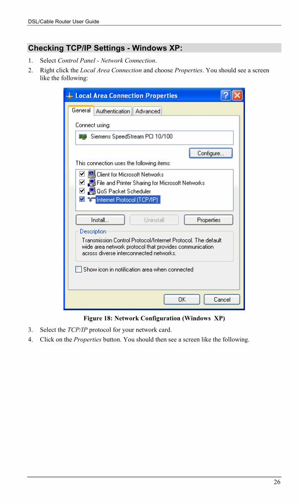
Checking TCP/IP Settings - Windows XP:1. Select Control Panel - Network Connection.2. Right click the Local Area Connection and choose Properties. You should see a screen
like the following:
Figure 18: Network Configuration (Windows XP)
3. Select the TCP/IP protocol for your network card.4. Click on the Properties button. You should then see a screen like the following.

PC Configuration
27
Figure 19: TCP/IP Properties (Windows XP)
5. Ensure your TCP/IP settings are correct.
Using DHCPTo use DHCP, select the radio button Obtain an IP Address automatically. This is the defaultWindows settings.
Restart your PC to ensure it obtains an IP Address from the DSL/Cable Router.
Using a fixed IP Address ("Use the following IP Address")• If your PC is already configured, do NOT change the settings on the screen shown in
Figure 19 above, unless advised to do so by your network administrator.• You can enter the DSL/Cable Router's IP address in the Default gateway field and click
OK. Your LAN administrator can advise you of the IP Address they assigned to theDSL/Cable Router.
• If the DNS Server fields are empty, select Use the following DNS server addresses, andenter the DNS address or addresses provided by your ISP, then click OK.
DSL/Cable Router User Guide
28
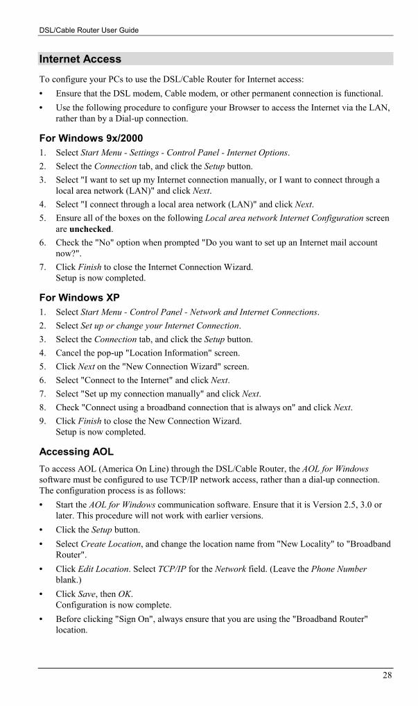
Internet AccessTo configure your PCs to use the DSL/Cable Router for Internet access:• Ensure that the DSL modem, Cable modem, or other permanent connection is functional.• Use the following procedure to configure your Browser to access the Internet via the LAN,
rather than by a Dial-up connection.
For Windows 9x/20001. Select Start Menu - Settings - Control Panel - Internet Options.2. Select the Connection tab, and click the Setup button.3. Select "I want to set up my Internet connection manually, or I want to connect through a
local area network (LAN)" and click Next.4. Select "I connect through a local area network (LAN)" and click Next.5. Ensure all of the boxes on the following Local area network Internet Configuration screen
are unchecked.6. Check the "No" option when prompted "Do you want to set up an Internet mail account
now?".7. Click Finish to close the Internet Connection Wizard.
Setup is now completed.
For Windows XP1. Select Start Menu - Control Panel - Network and Internet Connections.2. Select Set up or change your Internet Connection.3. Select the Connection tab, and click the Setup button.4. Cancel the pop-up "Location Information" screen.5. Click Next on the "New Connection Wizard" screen.6. Select "Connect to the Internet" and click Next.7. Select "Set up my connection manually" and click Next.8. Check "Connect using a broadband connection that is always on" and click Next.9. Click Finish to close the New Connection Wizard.
Setup is now completed.
Accessing AOLTo access AOL (America On Line) through the DSL/Cable Router, the AOL for Windowssoftware must be configured to use TCP/IP network access, rather than a dial-up connection.The configuration process is as follows:• Start the AOL for Windows communication software. Ensure that it is Version 2.5, 3.0 or
later. This procedure will not work with earlier versions.• Click the Setup button.• Select Create Location, and change the location name from "New Locality" to "Broadband
Router".• Click Edit Location. Select TCP/IP for the Network field. (Leave the Phone Number
blank.)• Click Save, then OK.
Configuration is now complete.• Before clicking "Sign On", always ensure that you are using the "Broadband Router"
location.

PC Configuration
29
Printer Setup for WindowsThe DSL/Cable Router provides printing support for 2 methods for printing from Windows:• Printer Port Driver. After installing the Printer Port Driver, Windows users can print
directly to the DSL/Cable Router. Print jobs are spooled (queued) on each PC.The supplied Printer Port Driver supports Windows 95/98, Windows Me Windows NT4.0,Windows 2000 and Windows XP.
• LPD/LPR Printing. If using Windows NT 4.0 Server or Windows 2000 Server,LPD/LPR printing can be used. No software needs to be installed on either the WindowsServer or each client PC. Print jobs will be spooled (queued) on the Windows Server, andcan be managed using the standard Windows Server tools.
Print Port Driver SetupThe following procedure is for all versions of Windows (95/98/Me, NT4.0, 2000, XP). TheWindows "Add Printer" screens will vary depending on your version or Windows, but theprocedure is the same:
1. Insert the supplied CD-ROM into your drive. If the setup program does not start automati-cally, run SETUP.EXE in the root folder.
2. At the Select Components screen, select the Print Port Driver option.3. Follow the prompts to complete the installation.4. The Print Port Setup will then run, and the following screen will be displayed.
Figure 20: Print Port Setup
5. Select the desired device and port, and click the "Add" button.
DSL/Cable Router User Guide
30
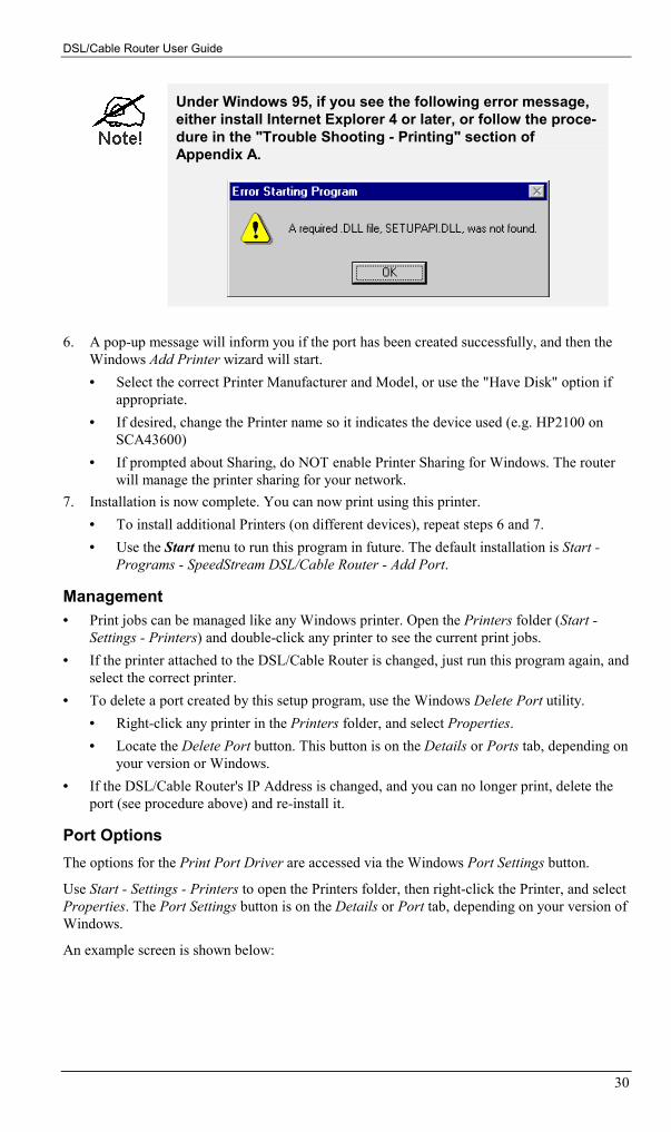
Under Windows 95, if you see the following error message,either install Internet Explorer 4 or later, or follow the proce-dure in the "Trouble Shooting - Printing" section ofAppendix A.
6. A pop-up message will inform you if the port has been created successfully, and then theWindows Add Printer wizard will start.• Select the correct Printer Manufacturer and Model, or use the "Have Disk" option if
appropriate.• If desired, change the Printer name so it indicates the device used (e.g. HP2100 on
SCA43600)• If prompted about Sharing, do NOT enable Printer Sharing for Windows. The router
will manage the printer sharing for your network.7. Installation is now complete. You can now print using this printer.
• To install additional Printers (on different devices), repeat steps 6 and 7.• Use the Start menu to run this program in future. The default installation is Start -
Programs - SpeedStream DSL/Cable Router - Add Port.
Management• Print jobs can be managed like any Windows printer. Open the Printers folder (Start -
Settings - Printers) and double-click any printer to see the current print jobs.• If the printer attached to the DSL/Cable Router is changed, just run this program again, and
select the correct printer.• To delete a port created by this setup program, use the Windows Delete Port utility.
• Right-click any printer in the Printers folder, and select Properties.• Locate the Delete Port button. This button is on the Details or Ports tab, depending on
your version or Windows.• If the DSL/Cable Router's IP Address is changed, and you can no longer print, delete the
port (see procedure above) and re-install it.
Port OptionsThe options for the Print Port Driver are accessed via the Windows Port Settings button.
Use Start - Settings - Printers to open the Printers folder, then right-click the Printer, and selectProperties. The Port Settings button is on the Details or Port tab, depending on your version ofWindows.
An example screen is shown below:

PC Configuration
31
Figure 21: Print Port Configuration
Items shown on this screen are as follows:
Port If desired, click Browse to select a different device. (The SelectDevice Port button is provided to allow this software to workwith multi-port models.)
The Port Name is shown in the Printer's Properties.
Banner Check this option to print a banner page before each print job.• If using a PostScript Printer, check the PostScript box.• The User Name will be printed on the banner page.
RetryInterval
Sets how often Windows will poll the DSL/Cable Router toestablish a connection when the printer is busy. Increase thisvalue if you get too many warning messages.

DSL/Cable Router User Guide
32
LPD/LPR PrintingLPD/LPR printing can be used with Windows NT 4.0 Server or Windows 2000. No softwareneeds to be installed on client PCs.
Windows NT 4.0 Server ConfigurationTo use LPD printing, Microsoft TCP/IP Printing must be installed and enabled. This can bechecked using Start-Settings-Control Panel-Network - Services.
To install LPD printing using the DSL/Cable Router, follow this procedure:
1. Go to Start-Settings-Printer and invoke the Add Printer wizard.2. When prompted with "This printer will be managed by..", select My Computer and click
Next.3. Select Add Port, then select LPR Port and click New Port.4. In the Dialog requesting Name of Address of server providing lpd, enter the IP address of
the DSL/Cable Router.5. For Name of printer or print queue on that server, enter L16. Click OK. When returned to the Printer Ports window, simply select Close and then install
your printer driver as usual.7. When prompted whether or not the printer will be shared, select the Sharing radio button.8. In the Shared dialog box, enter the shared printer name. The shared name is how other
users will see this printer. You should advise client PCs of the Server name and this printername.
9. Click OK to save and exit.

PC Configuration
33
Windows 2000 Server Configuration
The LPD/LPR Port is not enabled by default. To enable it, use this procedure:
1. In Control Panel, select Add/Remove Programs, then Windows Components.2. Select Other Network File and Print Services, then click the Details button.
Figure 22: Adding LPD/LPR Port (Win 2000)
3. Enable Print Services for Unix, and click OK.4. Click Next and complete the Wizard.
Adding the Printer1. Open your Printers folder, and start the Add Printer Wizard.2. When prompted, select Local Printer.3. On the Select the Printer Port screen, select LPR Port, as shown below. Click Next to
continue.

DSL/Cable Router User Guide
34
Figure 23: Windows 2000: Select Port
4. In the Dialog requesting Name or Address of server providing lpd, enter the IP address ofthe DSL/Cable Router.
5. For Name of printer or print queue on that server, enter L16. Click OK, and then Next, and continue the Wizard.7. At the Select Sharing screen, select the Radio Button for Share As, and enter the shared
printer name. The shared name is how other users will see this printer. You should adviseclient PCs of the Server name and this printer name.
8. Complete the Add Printer wizard.
Client PC Setup for LPD/LPR PrintingAfter configuring the Windows Server, client PCs on the LAN can install the new printer.
The following procedure is for Windows 95/98/Me, Windows NT4.0, and Windows 2000workstation.1. Open your Printers folder, and start the Add Printer Wizard.2. When prompted, select Network Printer3. When prompted for Network Path or Queue Name, click the Browse button, and locate the
Server and Printer that your Network Administrator advised you to use.4. Click OK, then Next.5. Select the correct printer Manufacturer and Model, as advised by your Network Adminis-
trator, and click Next.6. Follow the prompts to complete the Wizard.7. The new printer will be listed with any other installed printers, and may be selected when
printing from any Windows application.

PC Configuration
35
Macintosh ClientsFrom your Macintosh, you can access the Internet via the DSL/Cable Router. The procedure isas follows.1. Open the TCP/IP Control Panel.2. Select Ethernet from the Connect via pop-up menu.3. Select Using DHCP Server from the Configure pop-up menu. The DHCP Client ID field
can be left blank.4. Close the TCP/IP panel, saving your settings.
Note:If using manually assigned IP addresses instead of DHCP, the required changes are:• Set the Router Address field to the DSL/Cable Router's IP Address.• Ensure your DNS settings are correct.
Linux ClientsTo access the Internet via the DSL/Cable Router, it is only necessary to set the DSL/CableRouter as the "Gateway".Ensure you are logged in as "root" before attempting any changes.
Fixed IP AddressBy default, most Unix installations use a fixed IP Address. If you wish to continue using a fixedIP Address, make the following changes to your configuration.• Set your "Default Gateway" to the IP Address of the DSL/Cable Router.• Ensure your DNS (Name server) settings are correct.
To act as a DHCP Client (recommended)The procedure below may vary according to your version of Linux and X -windows shell.1. Start your X Windows client.2. Select Control Panel - Network3. Select the "Interface" entry for your Network card. Normally, this will be called "eth0".4. Click the Edit button, set the "protocol" to "DHCP", and save this data.5. To apply your changes
• Use the "Deactivate" and "Activate" buttons, if available.• OR, restart your system.
Printing Setup on LinuxThe DSL/Cable Router supports LPD Printing on Linux.
• The DSL/Cable Router supports 3 "Logical Printers" under LPD. To configure the "Logi-cal Printers" on the DSL/Cable Router, refer to Printer Port in Chapter 7.
• The procedure to install a LPD printer is detailed below, but may vary according to yourversion of Linux and X -windows shell.
1. In your X Windows shell, select Control Panel, then Printer Configuration.

DSL/Cable Router User Guide
36
2. Select Add. For the printer type, select Remote Unix (lpd) Queue.3. Use the following data to complete the resulting dialog.
Field Data Example
Name Enter a name for this printer gw_prn
Spool Directory /var/spool/lpd/printer_nameWhere printer_name is the "Name"entry above.
/var/spool/lpd/gw_prn
File Limit Enter a suitable number. 0 (no limit)
DSL/Cable Router's IP address 192.168.254.254Remote Host
Note:If you have made a host file entry, you can use the name from thehost file instead of the IP Address.
Remote Queue LnWhere n is the Logical Printer number(L1, L2, L3). Logical Printers can beconfigured on the DSL/Cable Router'sAdvanced - Printer Port screen.
L1
4. Save this data, and exit the Printer Configuration. Configuration is now completed, and theprinter is now available for use.
Other Unix Systems
Internet Access• Ensure the "Gateway" field for your network card is set to the IP Address of the
DSL/Cable Router.• Ensure your DNS (Name Server) settings are correct.
Printing SetupTo use LPD printing to the DSL/Cable Router's printer, install an LPD printer using the stan-dard procedure for your system.• Use the DSL/Cable Router's IP Address as the location of the remote host.• Use L1, L2, or L3 for the name of the printer on the remote host.
On the DSL/Cable Router, the logical printers (L1, L2, and L3) can be configured on theAdvanced - Printer Port screen. See Printer Port in Chapter 7 for details.

37
Chapter 5
Operation and StatusThis Chapter details the operation of the DSL/Cable Router and the statusscreens.
Operation
Once both the DSL/Cable Router and the PCs are configured, operation is automatic.
However, there are some situations where additional Internet configuration may be required:• If using Internet-based Conferencing & Telephony applications, it may be necessary to
specify which PC receives an incoming connection. Refer to Chapter 6 - Advanced Fea-tures for further details.
• Applications that use non-standard connections or port numbers may be blocked by theDSL/Cable Router's built-in firewall. You can define such applications as Special Appli-cations to allow them to function normally. Refer to Chapter 6 - Advanced Features forfurther details.
• Some non-standard applications may require use of the DMZ feature. Refer to Chapter 6 -Advanced Features for further details.
5

DSL/Cable Router User Guide
38
Status ScreenUse the Status link on the main menu to view this screen.
Figure 24: Status Screen
Data - Status ScreenInternet
Connection Method This indicates the current connection method, as set in the SetupWizard.
Internet IP Address This IP Address is allocated by the ISP (Internet Service Pro-vider).
Connection Status Current connection status:• OK• No connection• Error
If there is an error, you can click the "Connection Details" buttonto find out more information.
"Access Log"Button
Click this button to open a sub-window and view details of out-going connections to the Internet. The log contains the followingdata:• Date/Time - When the connection was first established.• Source IP Address - The IP Address of the local PC re-

Operation and Status
39
questing the Internet connection.• Destination - The Internet address which was requested. If
the URL Filter is enabled, this address will be shown as aURL. Otherwise, the IP address will be displayed.
• Blocked - If the request was blocked by the URL Filterfunction, this will display "Yes". Otherwise, it will be blank.
"Connection Details"Button
Click this button to open a sub-window and view a detaileddescription of the current connection. Depending on the type ofconnection, a "log" may also be available.
LAN
IP Address The IP Address of the DSL/Cable Router.
Network Mask The Network Mask (Subnet Mask) for the IP Address above.
DHCP Server This shows the status of the DHCP Server function - either "En-abled" or "Disabled".
For additional information about the PCs on your LAN, and the IPaddresses allocated to them, use the Network Clients option on theAdvanced menu.
System
Device Name This displays the current name of the DSL/Cable Router.
Firmware Version The current version of the firmware installed in the DSL/CableRouter.
"System Data"Button
Clicking this button will open a Window which lists all systemdetails and settings.
Printer
Printer Status This indicates the current status of the printer. Possible values are:• Idle• Printing• Off-line• Out of paper
"Abort Current PrintJob" Button
Click this button to terminate the current print job. This buttonshould be used if the current print job is not printing correctly.
Buttons
Connection Details View the details of the current Internet connection. The sub-screen displayed will depend on the connection method used. Seethe following sections for details of each sub-screen.
Access Log View details of outgoing connections to the internet.
System Data Display all system information in a sub-window.
Abort CurrentPrint Job
Use this to terminate the current print job if is not printing cor-rectly.
Refresh Screen Update the data displayed on screen.

DSL/Cable Router User Guide
40
Connection Status - PPPoEIf using PPPoE (PPP over Ethernet), a screen like the following example will be displayedwhen the "Connection Details" button is clicked.
Figure 25: PPPoE Status Screen
Data - PPPoE Status ScreenConnection
Physical Address The hardware address of this device, as seen by remote devices onthe Internet. (This is different to the hardware address seen bydevices on the local LAN.)
IP Address The IP Address of this device, as seen by Internet users. Thisaddress is allocated by your ISP (Internet Service Provider).
Network Mask The Network Mask associated with the IP Address above.
PPPoE Link Status This indicates whether or not the connection is currently estab-lished.• If the connection does not exist, the "Connect" button can be
used to establish a connection.• If the connection currently exists, the "Disconnect" button
can be used to break the connection.
Connection Log
Connection Log • The Connection Log shows status messages relating to theexisting connection.
• The most common messages are listed in the table below.

Operation and Status
41
• The "Clear Log" button will restart the Log, while the Re-fresh button will update the messages shown on screen.
Buttons
Connect If not connected, establish a connection to your ISP.
Disconnect If connected to your ISP, hang up the connection.
Clear Log Delete all data currently in the Log. This will make it easier toread new messages.
Refresh Update the data on screen.
Connection Log Messages
Message Description
Connect on Demand Connection attempt has been triggered by the "Connect auto-matically, as required" setting.
Manual connection Connection attempt started by the "Connect" button.
Reset physical connection Preparing line for connection attempt.
Connecting to remoteserver
Attempting to connect to the ISP's server.
Remote Server located ISP's Server has responded to connection attempt.
Start PPP Attempting to login to ISP's Server and establish a PPP con-nection.
PPP up successfully Able to login to ISP's Server and establish a PPP connection.
Idle time-out reached The connection has been idle for the time period specified inthe "Idle Time-out" field. The connection will now be termi-nated.
Disconnecting The current connection is being terminated, due to either the"Idle Time-out" above, or "Disconnect" button being clicked.
Error: Remote Server notfound
ISP's Server did not respond. This could be a Server problem,or a problem with the link to the Server.
Error: PPP Connectionfailed
Unable to establish a PPP connection with the ISP's Server.This could be a login problem (name or password) or a Serverproblem.
Error: Connection toServer lost
The existing connection has been lost. This could be caused bya power failure, a link failure, or Server failure.
Error: Invalid or unknownpacket type
The data received from the ISP's Server could not be proc-essed. This could be caused by data corruption (from a badlink), or the Server using a protocol which is not supported bythis device.

DSL/Cable Router User Guide
42
Connection Status - PPTPIf using PPTP (Peer-to-Peer Tunneling Protocol), a screen like the following example will bedisplayed when the "Connection Details" button is clicked.
Figure 26: PPTP Status Screen
Data - PPTP Status ScreenConnection
Physical Address The hardware address of this device, as seen by remote devices on theInternet. (This is different to the hardware address seen by devices onthe local LAN.)
IP Address The IP Address of this device, as seen by Internet users. This addressis allocated by your ISP (Internet Service Provider).
PPTP Status This indicates whether or not the connection is currently established.• If the connection does not exist, the "Connect" button can be
used to establish a connection.• If the connection currently exists, the "Disconnect" button can be
used to break the connection.
Connection Log
Connection Log • The Connection Log shows status messages relating to theexisting connection.
• The "Clear Log" button will restart the Log, while the Refreshbutton will update the messages shown on screen.

Operation and Status
43
Buttons
Connect If not connected, establish a connection to your ISP.
Disconnect If connected to your ISP, hang up the connection.
Clear Log Delete all data currently in the Log. This will make it easier to readnew messages.
Refresh Update the data on screen.

DSL/Cable Router User Guide
44
Connection Details - Fixed/Dynamic IP AddressIf your access method is neither PPPoE nor PPTP, a screen like the following example will bedisplayed when the "Connection Details" button is clicked.
Figure 27: Connection Status Screen
Data - Connection Details ScreenInternet
Physical Address The hardware address of this device, as seen by remote devices on theInternet. (This is different to the hardware address seen by devices onthe local LAN.)
IP Address The IP Address of this device, as seen by Internet users. This addressis allocated by your ISP (Internet Service Provider).
Network Mask The Network Mask associated with the IP Address above.
Default Gateway The IP Address of the remote Gateway or Router associated with theIP Address above.
DNS IP Address The IP Address of the Domain Name Server which is currently used.
DHCP Client This will show "Enabled" or "Disabled", depending on whether or notthis device is functioning as a DHCP client.
If "Enabled" the "Remaining lease time" field indicates when the IPAddress allocated by the DHCP Server will expire. The lease isautomatically renewed on expiry; use the "Renew" button if you wishto manually renew the lease immediately.

Operation and Status
45
Buttons
Release/Renew
Button will displayEITHER"Release"OR"Renew"
This button is only useful if the IP address shown above is allocatedautomatically on connection. (Dynamic IP address). Otherwise, it hasno effect.• If the ISP's DHCP Server has NOT allocated an IP Address for
the DSL/Cable Router, this button will say "Renew". Clicking the"Renew" button will attempt to re-establish the connection andobtain an IP Address from the ISP's DHCP Server.
• If an IP Address has been allocated to the DSL/Cable Router (bythe ISP's DHCP Server), this button will say "Release". Clickingthe "Release" button will break the connection and release the IPAddress.
Refresh Update the data shown on screen.
46
Chapter 6
Advanced FeaturesThis Chapter explains when and how to use the DSL/Cable Router's "Ad-vanced" Features.
OverviewAll advanced features are accessed via the Advanced menu. The following advanced featuresare provided.• Special Applications• DMZ• Virtual Servers• Dynamic DNS• Remote Management• Access Control• Firmware Upgrade using your Web Browser
This chapter contains details of the configuration and use of each of these features.
Advanced Internet ScreenThis screen allows configuration of all advanced features relating to Internet access.• Conferencing and Telephony applications• Special Applications• DMZ• URL filter
An example screen is shown below.
6

Advanced Features
47
Figure 28: Advanced Internet Screen
Conferencing & TelephonyMost applications are supported transparently by the DSL/Cable Router. But sometimes it isnot clear which PC should receive an incoming connection. This problem could arise with thefollowing Conferencing & Telephony applications:• CUseeME• ICQ• ICU II (ICU 2)• Internet Phone• mIRC• MS NetMeeting• Yahoo Messenger
If this problem arises, you can use this screen to set which PC should receive an incomingconnection, as described below.
DSL/Cable Router User Guide
48
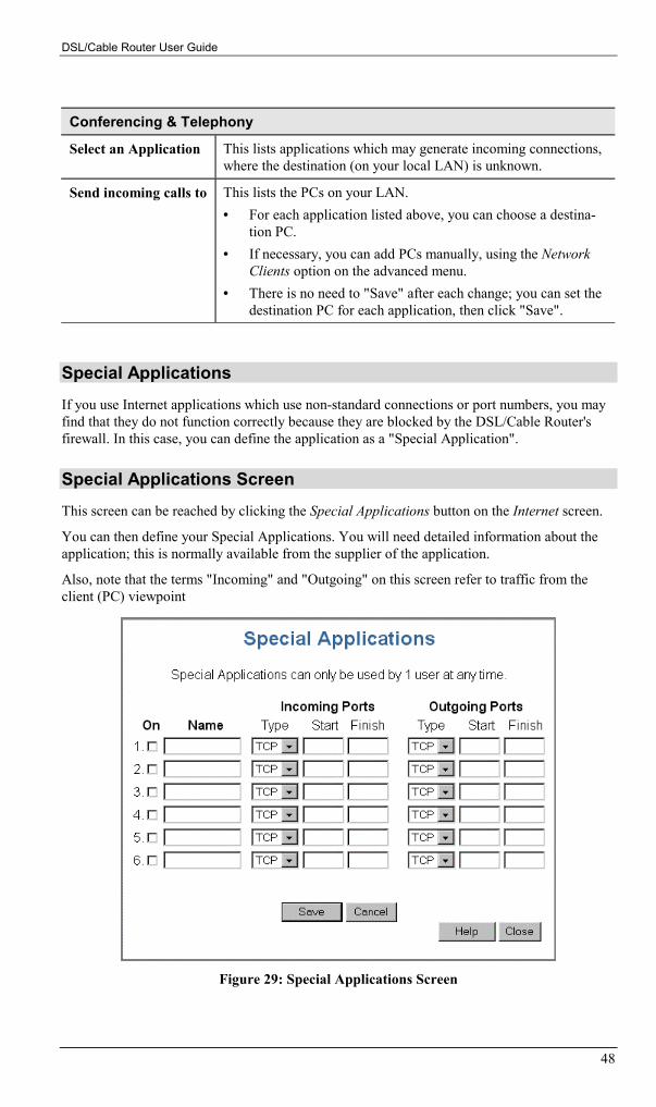
Conferencing & Telephony
Select an Application This lists applications which may generate incoming connections,where the destination (on your local LAN) is unknown.
Send incoming calls to This lists the PCs on your LAN.• For each application listed above, you can choose a destina-
tion PC.• If necessary, you can add PCs manually, using the Network
Clients option on the advanced menu.• There is no need to "Save" after each change; you can set the
destination PC for each application, then click "Save".
Special ApplicationsIf you use Internet applications which use non-standard connections or port numbers, you mayfind that they do not function correctly because they are blocked by the DSL/Cable Router'sfirewall. In this case, you can define the application as a "Special Application".
Special Applications ScreenThis screen can be reached by clicking the Special Applications button on the Internet screen.
You can then define your Special Applications. You will need detailed information about theapplication; this is normally available from the supplier of the application.
Also, note that the terms "Incoming" and "Outgoing" on this screen refer to traffic from theclient (PC) viewpoint
Figure 29: Special Applications Screen

Advanced Features
49
Data - Special Applications ScreenCheckbox Use this to Enable or Disable this Special Application as required.
Name Enter a descriptive name to identify this Special Application.
IncomingPorts
• Type - Select the protocol (TCP or UDP) used when you receive datafrom the special application or service. (Note: Some applications usedifferent protocols for outgoing and incoming data).
• Start - Enter the beginning of the range of port numbers used by theapplication server, for data you receive. If the application uses a singleport number, enter it in both the "Start" and "Finish" fields.
• Finish - Enter the end of the range of port numbers used by the applica-tion server, for data you receive.
OutgoingPorts
• Type - Select the protocol (TCP or UDP) used when you send data tothe remote system or service.
• Start - Enter the beginning of the range of port numbers used by theapplication server, for data you send to it. If the application uses a singleport number, enter it in both the "Start" and "Finish" fields.
• Finish - Enter the end of the range of port numbers used by the applica-tion server, for data you send to it. If the application uses a single portnumber, enter it in both the "Start" and "Finish" fields.
Using a Special Application• Configure the Special Applications screen as required.
• On your PC, use the application normally. Remember that only one (1) PC can use eachSpecial application at any time. Also, when 1 PC is finished using a particular Special Ap-plication, there may need to be a "Time-out" before another PC can use the same SpecialApplication. The "Time-out" period may be up to 3 minutes.
If an application still cannot function correctly,try using the "DMZ" feature.
DMZThis feature, if enabled, allows one (1) computer on your LAN to be exposed to all users on theInternet, allowing unrestricted 2-way communication between the "DMZ PC" and other Internetusers or Servers.• This allows almost any application to be used on the "DMZ PC".• The "DMZ PC" will receive all "Unknown" connections and data.• If the DMZ feature is enabled, you must select the PC to be used as the "DMZ PC".• The DMZ feature can be Enabled and Disabled on the Advanced Internet screen.
DSL/Cable Router User Guide
50
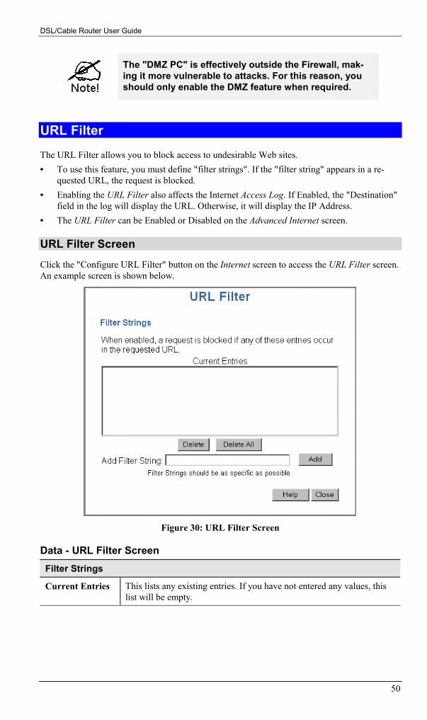
The "DMZ PC" is effectively outside the Firewall, mak-ing it more vulnerable to attacks. For this reason, youshould only enable the DMZ feature when required.
URL FilterThe URL Filter allows you to block access to undesirable Web sites.• To use this feature, you must define "filter strings". If the "filter string" appears in a re-
quested URL, the request is blocked.• Enabling the URL Filter also affects the Internet Access Log. If Enabled, the "Destination"
field in the log will display the URL. Otherwise, it will display the IP Address.• The URL Filter can be Enabled or Disabled on the Advanced Internet screen.
URL Filter ScreenClick the "Configure URL Filter" button on the Internet screen to access the URL Filter screen.An example screen is shown below.
Figure 30: URL Filter Screen
Data - URL Filter ScreenFilter Strings
Current Entries This lists any existing entries. If you have not entered any values, thislist will be empty.

Advanced Features
51
Add Filter String To add an entry to the list, enter it here, and click the "Add" button.An entry may be a Domain name (e.g. www.trash.com) or simply astring. (e.g. ads/ )Any URL that contains ANY entry ANYWHERE in the URL will beblocked.
Buttons
Delete/Delete All Use these buttons to delete the selected entry or all entries, as required.Multiple entries can be selected by holding down the CTRL key whileselecting.(On the Macintosh, hold the SHIFT key while selecting.)
Add Use this to add the current Filter String to the site list.

DSL/Cable Router User Guide
52
Virtual ServersThis feature allows you to make Servers on your LAN accessible to Internet users. Normally,Internet users would not be able to access a server on your LAN because:• Your Server does not have a valid external IP Address.• Attempts to connect to devices on your LAN are blocked by the firewall in this device.
The "Virtual Server" feature solves these problems and allows Internet users to connect to yourservers, as illustrated below.
DSL/CableRouterWeb Server FTP Server
Internet
Remote PC Remote PCUsing Web Server Using FTP Server(http://203.70.212.52)
203.70.212.52
192.168.254.254
(192.168.254.10) (192.168.254.20)
(LAN IP Address)
(WAN IP Address)
(ftp://203.70.212.52)
Figure 31: Virtual Servers
IP Address seen by Internet UsersNote that, in this illustration, both Internet users are connecting to the same IP Address, butusing different protocols.
To Internet users, all virtual Servers on your LAN have the same IP Address.This IP Address is allocated by your ISP.This address should be static, rather than dynamic, to make it easier for Internet users to con-nect to your Servers.However, you can use the DDNS (Dynamic DNS) feature to allow users to connect to yourVirtual Servers using a URL, instead of an IP Address.

Advanced Features
53
Virtual Servers ScreenThe Virtual Servers screen is reached by the Virtual Servers link on the Advanced screen. Anexample screen is shown below.
Figure 32: Virtual Servers Screen
This screen lists a number of pre-defined Servers, and allows you to define your own Servers.Details of the selected Server are shown in the "Properties" area.
Data - Virtual Servers ScreenServers
Servers This lists a number of pre-defined Servers, plus any Servers youhave defined. Details of the selected Server are shown in the "Prop-erties" area.
Properties
Enable Use this to Enable or Disable support for this Server, as required.• If Enabled, any incoming connections will be forwarded to the
selected PC.• If Disabled, any incoming connection attempts will be blocked.
PC (Server) Select the PC for this Server. The PC must be running the appropri-ate Server software.
Protocol Select the protocol (TCP or UDP) used by the Server.
Internal Port No. Enter the port number which the Server software is configured touse.

DSL/Cable Router User Guide
54
External Port No. The port number used by Internet users when connecting to theServer. This is normally the same as the Internal Port Number. If itis different, this device will perform a "mapping" or "translation"function, allowing the server to use one port address, while clientsuse a different port address.
Buttons
Defaults This will delete any Servers you have defined, and set the pre-defined Servers to use their default port numbers.
Disable All This will cause the "Enable" setting of all Virtual Servers to be setOFF.
Add Add a new entry to the Virtual Server list, using the data shown inthe "Properties" area on screen. The entry selected in the list isignored, and has no effect.
Update Update the current Virtual Server entry, using the data shown in the"Properties" area on screen.
Delete Delete the current Virtual Server entry. Note that the pre-definedServers can not be deleted. Only Servers you have defined yourselfcan be deleted.
Clear Form Clear all data from the "Properties" area, ready for input of a newVirtual Server entry.
Show All List all entries in the Virtual Server database. The list will be in newwindow, allowing saving or printing of this data.
For each entry, the PC must be running theappropriate Server software.
Defining your own Virtual ServersIf the type of Server you wish to use is not listed on the Virtual Servers screen, you can defineand manage your own Servers:
Create a new Server: 1. Click "Clear Form"2. Enter the required data, as described above.3. Click "Add".4. The new Server will now appear in the list.
Modify (Edit) a Server: 1. Select the desired Server from the list2. Make any desired changes (for example, change the
Enable/Disable setting).3. Click "Update" to save changes to the selected Server.
Delete a Server: 1. Select the entry from the list.2. Click "Delete".
Note: You can only delete Servers you have defined. Pre-defined Server cannot be deleted.

Advanced Features
55
View all Settings of allServers
Click the "Show All" button. This will generate a report in anew window, where is can be printed or saved, as well asviewed.
From the Internet, ALL Virtual Servers have the IPAddress allocated by your ISP.
Connecting to the Virtual ServersOnce configured, anyone on the Internet can connect to your Virtual Servers. They must use theInternet IP Address (the IP Address allocated to you by your ISP).e.g.
http://203.70.212.52
ftp://203.70.212.52
It is more convenient if you are using a Fixed IP Address from your ISP, rather than Dynamic.However, you can use the Dynamic DNS feature, described in the following section, to allowusers to connect to your Virtual Servers using a URL, rather than an IP Address.
Dynamic DNSThis free service is very useful when combined with the Virtual Server feature. It allows Inter-net users to connect to your Virtual Servers using a URL, rather than an IP Address.
This also solves the problem of having a dynamic IP address. With a dynamic IP address, yourIP address may change whenever you connect, which makes it difficult to connect to you.
The Service works as follows:1. You must register for the service at http://www.dyndns.org (Registration is free). Your
password will be E-mailed to you.2. After registration, use the "Create New Host" option (at www.dyndns.org) to request your
desired Domain name.3. Enter your data from www.dyndns.org in the DSL/Cable Router's DDNS screen.4. The DSL/Cable Router will then automatically ensure that your current IP Address is
recorded at http://www.dyndns.org5. From the Internet, users will be able to connect to your Virtual Servers (or DMZ PC) using
your Domain name, as shown on this screen.
DSL/Cable Router User Guide
56
Dynamic DNS Screen
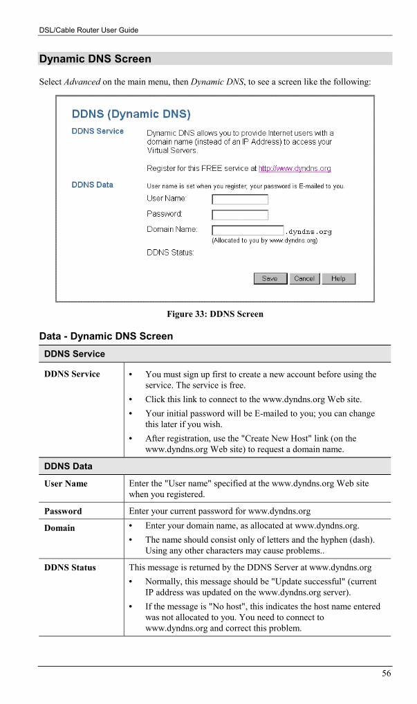
Select Advanced on the main menu, then Dynamic DNS, to see a screen like the following:
Figure 33: DDNS Screen
Data - Dynamic DNS ScreenDDNS Service
DDNS Service • You must sign up first to create a new account before using theservice. The service is free.
• Click this link to connect to the www.dyndns.org Web site.• Your initial password will be E-mailed to you; you can change
this later if you wish.• After registration, use the "Create New Host" link (on the
www.dyndns.org Web site) to request a domain name.
DDNS Data
User Name Enter the "User name" specified at the www.dyndns.org Web sitewhen you registered.
Password Enter your current password for www.dyndns.org
Domain • Enter your domain name, as allocated at www.dyndns.org.• The name should consist only of letters and the hyphen (dash).
Using any other characters may cause problems..
DDNS Status This message is returned by the DDNS Server at www.dyndns.org• Normally, this message should be "Update successful" (current
IP address was updated on the www.dyndns.org server).• If the message is "No host", this indicates the host name entered
was not allocated to you. You need to connect towww.dyndns.org and correct this problem.

Advanced Features
57
Remote ManagementThis feature allows you to manage the DSL/Cable Router via the Internet.
Figure 34: Remote Screen
Data - Remote Management ScreenRemote Management
Enable RemoteManagement
Enable to allow management via the Internet. If Disabled, this devicewill ignore management connection attempts from the Internet.
Port Number Enter a port number between 1024 and 65535 (8080 is recom-mended). This port number must be specified when you connect (seebelow).
Note: The default port number for HTTP (Web) connections is port80, but using port 80 here will prevent the use of a Web "VirtualServer" on your LAN. (See Advanced Internet - Virtual Servers)
Current IP Ad-dress
You must use this IP Address to connect (see below).
This IP Address is allocated by your ISP. But if using a Dynamic IPAddress, this value can change each time you connect to your ISP. Soit is better if your ISP allocates you a Fixed IP Address.
To connect from a remote PC via the Internet1. Ensure your Internet connection is established, and start your Web Browser.2. In the "Address" bar, enter "HTTP://" followed by the Internet IP Address of the
DSL/Cable Router. If the port number is not 80, the port number is also required. (Afterthe IP Address, enter ":" followed by the port number.)e.g.
HTTP://123.123.123.123:8080
This example assumes the WAN IP Address is 123.123.123.123, and the port number is 8080.

DSL/Cable Router User Guide
58
Access ControlThis feature is accessed by the Access Control link on the Advanced menu.
OverviewThe Access Control feature allows administrators to restrict Internet Access by individual PCs.With the default settings, everyone has unrestricted Internet access.
To use this feature:1. Set the desired restrictions on the "Default" group. All PCs are in the "Default" group
unless explicitly moved to another group.2. Set the desired restrictions on the other groups ("Group 1", "Group 2", "Group 3" and
"Group 4") as needed.3. Assign PCs to the groups as required.
Restrictions are imposed by blocking "Services", or typesof connections. All common Services are pre-defined.If required, you can also define your own Services.
Access Control LogTo check the operation of the Access Control feature, an Access Control Log is provided. Clickthe View Log button on the Access Control screen to view this log.
This log shows attempted Internet accesses which have been blocked by the Access Controlfunction.
Data shown in this log is as follows:
Date/Time Date and Time of the attempted access.
Name If known, the name of the PC whose access was blocked. This nameis taken from the Network Clients database
Source IP address The IP Address of the PC or device whose access request wasblocked
MAC address The hardware or physical address of the PC or device whose accessrequest was blocked
Destination The destination URL or IP address

Advanced Features
59
Access Control ScreenTo view this screen, select the Access Control link on the Advanced menu.
Figure 35: Access Control Screen
Data - Access Control ScreenGroup
Select Group Select the desired Group. The screen will update to display thesettings for the selected Group. Groups are named "Default","Group 1", "Group 2", "Group 3" and "Group 4", and cannot be re-named.
"Members" Button Click this button to add or remove members from the currentGroup.
If the current group is "Default", then members can not be added ordeleted. This group contains PCs not allocated to any other group.
See the following section for details of the Group Members screen.
Access Rights
Internet Access Select the desired options for the current group, as detailed below.
No Restriction Nothing is blocked. Use this to create the least restrictive group.
Block All Access All traffic via the WAN port is blocked. Use this to create the mostrestrictive group.

DSL/Cable Router User Guide
60
Use List Below -block SelectedServices
You can select which Services are allowed, and which are blocked.Use this to gain fine control over a group.
Services
Defined Services Select the applications you wish to block.
Multiple Services can be selected by holding the CTRL key (on theMacintosh, the SHIFT key) while selecting.
Selected Services are blocked.
"Services" button Click this to open the Services window, allowing you to define yourown Services.
See the following section for details of the Services screen.
Buttons
Members Click this button to add or remove members from the currentGroup.
If the current group is "Default", then members can not be added ordeleted. This group contains PCs not allocated to any other group.
See the following section for details of the Group Members screen.
Service Click this button to add or remove services from the current list.
Save Save the data on screen.
Cancel Reverse any changes made since the last "Save".
View Log See all the details in the Log.
Clear Log Delete all data currently in the Log. This will make it easier to readnew entries.

Advanced Features
61
Group Members ScreenThis screen is displayed when the Members button on the Access Control screen is clicked.
Figure 36: Group Members
Use this screen to add or remove members (PCs) from the current group.• The "Del >>" button will remove the selected PC (in the Members list) from the current
group.• The "<< Add" button will add the selected PC (in the Other PCs list) to the current group.
PCs not assigned to any group will be in the "Default"group.PCs deleted from any other Group will be added to the"Default" group.

DSL/Cable Router User Guide
62
Services ScreenThis screen is displayed when the Services button on the Access Control screen is clicked.
Figure 37: Services
Data - Services ScreenAvailable Services
Available Services This lists all the available services.
"Delete" button Use this to delete any Service you have added. Pre-defined Servicescan not be deleted.
Add New Service
Name Enter a descriptive name to identify this service.
Type Select the protocol (TCP, UDP, ICMP) used to the remote system orservice.
Start Port For TCP and UDP Services, enter the beginning of the range of portnumbers used by the service. If the service uses a single port number,enter it in both the "Start" and "Finish" fields.
Finish Port For TCP and UDP Services, enter the end of the range of port num-bers used by the service. If the service uses a single port number,enter it in both the "Start" and "Finish" fields.
ICMP Type For ICMP Services, enter the type number of the required service.
Buttons
Delete Delete the selected service from the list.
Add Add a new entry to the Service list, using the data shown in the "Add

Advanced Features
63
New Service" area on screen.
Cancel Clear the " Add New Service " area, ready for entering data for a newService.
Firmware UpgradeThe firmware (software) in the DSL/Cable Router can be upgraded using your Web Browser.
You must first download the upgrade file, then select Upgrade on the Advanced menu. Youwill see a screen like the following.
Figure 38: Upgrade Firmware
To perform the Firmware Upgrade:1. Click the "Browse" button and navigate to the location of the upgrade file.2. Select the upgrade file. It's name will appear in the Upgrade File field.3. Click the "Start Upgrade" button to commence the firmware upgrade.
The DSL/Cable Router is unavailable during theupgrade process, and must restart when the upgradeis completed. Any connections to or through theDSL/Cable Router will be lost.
64
Chapter 7
Advanced ConfigurationThis Chapter explains the settings available via the Advanced configurationsection of the "Advanced" menu.
OverviewNormally, it is not necessary to use these screens, or change any settings. These screens andsettings are provided to deal with non-standard situations, or to provide additional options foradvanced users.
The settings available are:
Network Clients This is the list of PCs shown when you select the "DMZ PC" or a"Virtual Server". This database is maintained automatically, but youcan add and delete entries for PCs which use a Fixed (Static) IPAddress.
Options Various options, including DNS and UPnP.
Printer Configure Logical Printers for use under Unix
MAC Address Set the MAC (hardware) address used on the Internet (WAN port)interface. This is required only if your ISP has recorded the MAC(hardware) address you should use.
Routing Only required if your LAN has other Routers or Gateways.
Security Firewall settings.
7

Advanced Configuration
65
Network Clients ScreenThe Network Clients database is used whenever you need to select a PC (e.g. for the "DMZ"PC). It eliminates the need to enter IP addresses. An example Network Clients screen is shownbelow.
Figure 39: Network Clients Screen
• PCs that are "DHCP Clients" are automatically added to the database, and updated asrequired.
• By default, non-Server versions of Windows act as "DHCP Clients"; this setting is called"Obtain an IP Address automatically".
• The DSL/Cable Router uses the "Hardware Address" to identify each PC, not the name orIP address. The "Hardware Address" can only change if you change the PC's network cardor adapter.
• This system means you do NOT need to use Fixed (static) IP addresses on your LAN.However, you can add PCs using Fixed (static) IP Addresses to the Network Clients data-base if required.
Data - Network Clients ScreenNetwork Clients
Known PCs This lists all current entries. Data displayed is name (IP Address) type.For this model, the "type" will always be "LAN"
Name If adding a new PC to the list, enter its name here. It is best if thismatches the PC's "hostname".
IP Address Enter the IP Address of the PC. The PC will be sent a "ping" to deter-mine its hardware address. If the PC is not available (not connected, ornot powered On) you will not be able to add it.

DSL/Cable Router User Guide
66
Buttons
Add This will add the new PC to the list. The PC will be sent a "ping" todetermine its hardware address. If the PC is not available (not con-nected, or not powered On) you will not be able to add it.
Delete Delete the selected PC from the list. This should be done in 2 situa-tions:• The PC has been removed from your LAN.• The entry is incorrect.
Refresh Update the data on screen.
Generate Report Display a read-only list showing full details of all entries in the Net-work Clients database.

Advanced Configuration
67
OptionsThis screen allows advanced users to enter or change a number of settings. For normal opera-tion, there is no need to use this screen or change any settings. An example Options screen isshown below.
Figure 40: Options Screen
Data - Options ScreenBackup DNS
IP Address Enter the IP Address of the DNS (Domain Name Servers) here. TheseDNS will be used only if the primary DNS is unavailable.
TFTP
Enable Firm-ware Upgradeusing TFTP
• If enabled, TFTP (Trivial FTP) can be used to upgrade the firm-ware in this device. This is normally not required; a Windowsutility is available for this purpose.
• You must obtain the firmware upgrade file first; instructions forusing TFTP will be available with the upgrade.
UPnP
Enable UPnPServices
• UPnP (Universal Plug and Play) allows automatic discovery andconfiguration of equipment attached to your LAN. UPnP is bysupported by Windows ME, XP, or later.
• If Enabled, this device will be visible via UPnP.• If Disabled, this device will not be visible via UPnP.
Allow Configu-ration...
• If checked, then UPnP users can change the configuration.• If Disabled, UPnP users can only view the configuration.

DSL/Cable Router User Guide
68
Allow Internetaccess to bedisabled
• If checked, then UPnP users can disable Internet access via thisdevice.
• If Disabled, UPnP users can NOT disable Internet access via thisdevice.
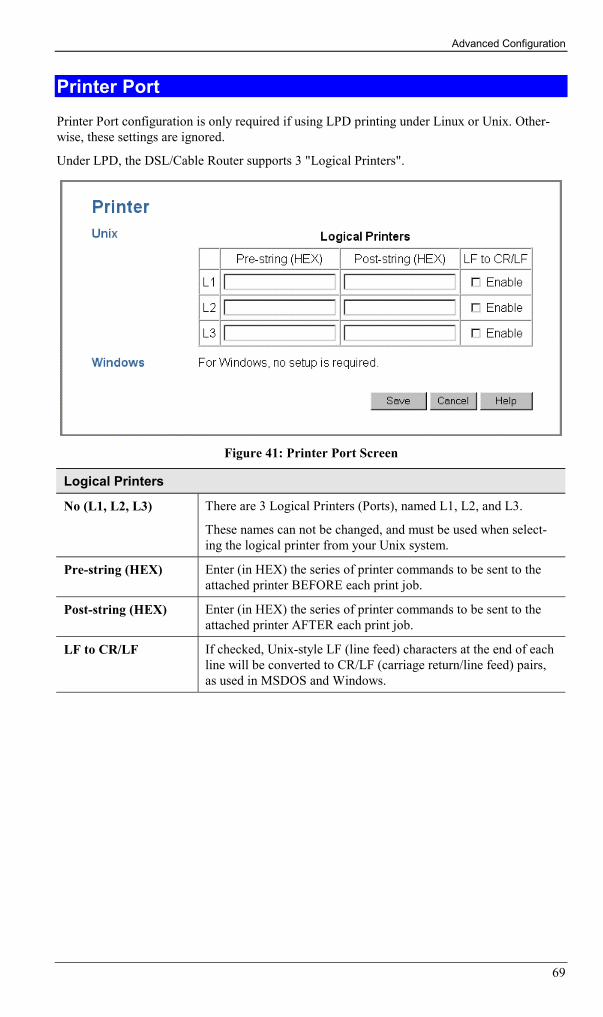
Advanced Configuration
69
Printer PortPrinter Port configuration is only required if using LPD printing under Linux or Unix. Other-wise, these settings are ignored.
Under LPD, the DSL/Cable Router supports 3 "Logical Printers".
Figure 41: Printer Port Screen
Logical Printers
No (L1, L2, L3) There are 3 Logical Printers (Ports), named L1, L2, and L3.
These names can not be changed, and must be used when select-ing the logical printer from your Unix system.
Pre-string (HEX) Enter (in HEX) the series of printer commands to be sent to theattached printer BEFORE each print job.
Post-string (HEX) Enter (in HEX) the series of printer commands to be sent to theattached printer AFTER each print job.
LF to CR/LF If checked, Unix-style LF (line feed) characters at the end of eachline will be converted to CR/LF (carriage return/line feed) pairs,as used in MSDOS and Windows.

DSL/Cable Router User Guide
70
MAC AddressThe MAC (hardware) address is a low-level network identifier. It may be called "MAC Ad-dress", "Hardware Address", or "Physical Address". On a PC, this address is associated withthe Network card or adapter. The address on the MAC Address screen is the address on theInternet (WAN port) interface, and has no effect on the LAN interface.• If your ISP asks for the "Network Adapter Address", "Physical Address", "Hardware
Address", or "MAC Address" for the PC the DSL/Cable modem is connected to, providethis value.
• If your ISP has already recorded a MAC address, you can change the address used by theDSL/Cable Router to match the address recorded by your ISP.
MAC Address ScreenSelect MAC Address from the Advanced menu to reach a screen like the example below.
Figure 42: MAC address screen
Data - MAC address Screen
MAC (hardware)Address
The current MAC (hardware) address is displayed.
If your ISP has recorded a Hardware Address, you can "spoof" thataddress by entering it in the address field. The hardware addressconsists of 12 characters, where each character is a digit (0..9) or acharacter between A and F.
Buttons
Default Inserts the default MAC address into the MAC address field. Youmust click "Save" to actually change the address used.
Clone MACAddress
Inserts the MAC address from your PC into the MAC address field.You must click "Save" to actually change the address used.
Save Save your changes to the DSL/Cable Router.
Cancel Reverse any changes made since the last "Save".
If the MAC address is changed, the DSL/CableRouter must be restarted.
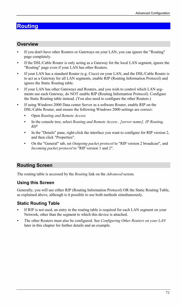
Advanced Configuration
71
Routing
Overview• If you don't have other Routers or Gateways on your LAN, you can ignore the "Routing"
page completely.• If the DSL/Cable Router is only acting as a Gateway for the local LAN segment, ignore the
"Routing" page even if your LAN has other Routers.• If your LAN has a standard Router (e.g. Cisco) on your LAN, and the DSL/Cable Router is
to act as a Gateway for all LAN segments, enable RIP (Routing Information Protocol) andignore the Static Routing table.
• If your LAN has other Gateways and Routers, and you wish to control which LAN seg-ments use each Gateway, do NOT enable RIP (Routing Information Protocol). Configurethe Static Routing table instead. (You also need to configure the other Routers.)
• If using Windows 2000 Data center Server as a software Router, enable RIP on theDSL/Cable Router, and ensure the following Windows 2000 settings are correct:• Open Routing and Remote Access• In the console tree, select Routing and Remote Access , [server name], IP Routing,
RIP• In the "Details" pane, right-click the interface you want to configure for RIP version 2,
and then click "Properties".• On the "General" tab, set Outgoing packet protocol to "RIP version 2 broadcast", and
Incoming packet protocol to "RIP version 1 and 2".
Routing ScreenThe routing table is accessed by the Routing link on the Advanced screen.
Using this ScreenGenerally, you will use either RIP (Routing Information Protocol) OR the Static Routing Table,as explained above, although is it possible to use both methods simultaneously.
Static Routing Table• If RIP is not used, an entry in the routing table is required for each LAN segment on your
Network, other than the segment to which this device is attached.• The other Routers must also be configured. See Configuring Other Routers on your LAN
later in this chapter for further details and an example.
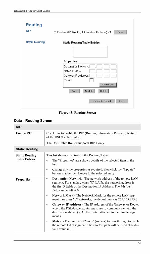
DSL/Cable Router User Guide
72
Figure 43: Routing Screen
Data - Routing ScreenRIP
Enable RIP Check this to enable the RIP (Routing Information Protocol) featureof the DSL/Cable Router.
The DSL/Cable Router supports RIP 1 only.
Static Routing
Static RoutingTable Entries
This list shows all entries in the Routing Table.• The "Properties" area shows details of the selected item in the
list.• Change any the properties as required, then click the "Update"
button to save the changes to the selected entry.
Properties • Destination Network - The network address of the remote LANsegment. For standard class "C" LANs, the network address isthe first 3 fields of the Destination IP Address. The 4th (last)field can be left at 0.
• Network Mask - The Network Mask for the remote LAN seg-ment. For class "C" networks, the default mask is 255.255.255.0
• Gateway IP Address - The IP Address of the Gateway or Routerwhich the DSL/Cable Router must use to communicate with thedestination above. (NOT the router attached to the remote seg-ment.)
• Metric - The number of "hops" (routers) to pass through to reachthe remote LAN segment. The shortest path will be used. The de-fault value is 1.

Advanced Configuration
73
Buttons
Save Save the RIP setting. This has no effect on the Static Routing Table.
Add Add a new entry to the Static Routing table, using the data shown inthe "Properties" area on screen. The entry selected in the list isignored, and has no effect.
Update Update the current Static Routing Table entry, using the data shownin the "Properties" area on screen.
Delete Delete the current Static Routing Table entry.
Clear Form Clear all data from the "Properties" area, ready for input of a newentry for the Static Routing table.
Generate Report Generate a read-only list of all entries in the Static Routing table.
Configuring Other Routers on your LANIt is essential that all IP packets for devices not on the local LAN be passed to the DSL/CableRouter, so that they can be forwarded to the external LAN, WAN, or Internet. To achieve this,the local LAN must be configured to use the DSL/Cable Router as the Default Route or DefaultGateway.
Local RouterThe local router is the Router installed on the same LAN segment as the DSL/Cable Router.This router requires that the Default Route is the DSL/Cable Router itself. Typically, routershave a special entry for the Default Route. It should be configured as follows.
Destination IP Address Normally 0.0.0.0, but check your router documentation.
Network Mask Normally 0.0.0.0, but check your router documentation.
Gateway IP Address The IP Address of the DSL/Cable Router.
Metric 1
Other Routers on the Local LANOther routers on the local LAN must use the DSL/Cable Router's Local Router as the DefaultRoute. The entries will be the same as the DSL/Cable Router's local router, with the exceptionof the Gateway IP Address.• For a router with a direct connection to the DSL/Cable Router's local Router, the Gateway
IP Address is the address of the DSL/Cable Router's local router.• For routers which must forward packets to another router before reaching the DSL/Cable
Router's local router, the Gateway IP Address is the address of the intermediate router.

DSL/Cable Router User Guide
74
Static Routing - Example
Router B(192.168.1.90) (192.168.2.70)
Router A
Segment 0
Segment 2
Segment 1
DSL/Cable(192.168.254.xx)(192.168.1.xx)
(192.168.254.1)
(192.168.2.xx)
(192.168.1.80)
Router(192.168.254.254)
Figure 44: Routing Example
For the DSL/Cable Router's Routing TableFor the LAN shown above, with 2 routers and 3 LAN segments, the DSL/Cable Router requires2 entries as follows.
Entry 1 (Segment 1)Destination IP Address 192.168.1.0
Network Mask 255.255.255.0 (Standard Class C)
Gateway IP Address 192.168.254.1 (DSL/Cable Router's localRouter)
Metric 1
Entry 2 (Segment 2)Destination IP Address 192.168.2.0
Network Mask 255.255.255.0 (Standard Class C)
Gateway IP Address 192.168.254.1 (DSL/Cable Router's localRouter)
Metric 2
For Router A's Default RouteDestination IP Address 0.0.0.0
Network Mask 0.0.0.0
Gateway IP Address 192.168.254.254 (DSL/Cable Router's IPAddress)
For Router B's Default RouteDestination IP Address 0.0.0.0
Network Mask 0.0.0.0
Gateway IP Address 192.168.254.254 (DSL/Cable Router's localrouter)

Advanced Configuration
75
SecurityThe security screen is accessed by the Security option on the Advanced menu.
Figure 45: Security Screen
Data - Security ScreenFirewall
Enable DoSFirewall
If enabled, DoS (Denial of Service) attacks will be detected andblocked. The default is enabled. It is strongly recommended that thissetting be left enabled.
Note:• A DoS attack does not attempt to steal data or damage your PCs,
but overloads your Internet connection so you can not use it - theservice is unavailable.
• The DSL/Cable Router uses "Stateful Inspection" technology. Thissystem can detect situations where individual TCP/IP packets arevalid, but collectively they become a DoS attack.
Threshold This setting affects the number of "half-open" connections allowed.• A "half-open" connection arises when a remote client contacts the
Server with a connection request, but then does not reply to theServer's response.
• While the optimum number of "half-open" connections allowed(the "Threshold") depends on many factors, the most importantfactor is the available bandwidth of your Internet connection.
• Select the setting to match the bandwidth of your Internet connec-tion.

DSL/Cable Router User Guide
76
ICMP (Ping)
Respond toICMP (ping)
The ICMP protocol is used by the "ping" and "traceroute" programs,and by network monitoring and diagnostic programs.• If checked, the DSL/Cable Router will respond to ICMP packets
received from the Internet.• If not checked, ICMP packets from the Internet will be ignored.
Disabling this option provides a slight increase in security.

77
Appendix A
TroubleshootingThis Appendix covers the most likely problems and their solutions.
OverviewThis chapter covers some common problems that may be encountered while using theDSL/Cable Router and some possible solutions to them. If you follow the suggested steps andthe DSL/Cable Router still does not function properly, contact your dealer for further advice.
General Problems
Problem 1: Can't connect to the DSL/Cable Router to configure it.
Solution 1: Check the following:• The DSL/Cable Router is properly installed, LAN connections are OK,
and it is powered ON. Check the LEDs for port status.• Ensure that your PC and the DSL/Cable Router are on the same network
segment. (If you don't have a router, this must be the case.)• If your PC is set to "Obtain an IP Address automatically" (DHCP
client), restart it.• If your PC uses a Fixed (Static) IP address, ensure that it is using an IP
Address within the range 192.168.254.1 to 192.168.254.253 and thuscompatible with the DSL/Cable Router's default IP Address of192.168.254.254.Also, the Network Mask should be set to 255.255.255.0 to match theDSL/Cable Router.In Windows, you can check these settings by using Control Panel-Network to check the Properties for the TCP/IP protocol.
Internet AccessProblem 1: When I enter a URL or IP address I get a time out error.
Solution 1: A number of things could be causing this. Try the following troubleshootingsteps.• Check if other PCs work. If they do, ensure that your PCs IP settings are
correct. If using a Fixed (Static) IP Address, check the Network Mask,Default gateway and DNS as well as the IP Address.
• If the PCs are configured correctly, but still not working, check theDSL/Cable Router. Ensure that it is connected and ON. Connect to itand check its settings. (If you can't connect to it, check the LAN andpower connections.)
• If the DSL/Cable Router is configured correctly, check your Internetconnection (DSL/Cable modem etc) to see that it is working correctly.
Problem 2: Some applications do not run properly when using the DSL/CableRouter.
A

DSL/Cable Router User Guide
78
Solution 2: The DSL/Cable Router processes the data passing through it, so it is nottransparent.
Use the Special Applications feature to allow the use of Internet applicationswhich do not function correctly.
If this does solve the problem you can use the DMZ function. This shouldwork with almost every application, but:• It is a security risk, since the firewall is disabled for the DMZ PC.• Only one (1) PC can use this feature.
PrintingProblem 1: When I tried to install the Printing software for Peer-to-Peer printing, I
received an error message and the installation was aborted..
Solution 1: This may be caused by an existing installation of the printer port software.Before attempting another installation:• Remove the existing installation• Restart your PC
To remove an existing printer port installation:1. Open Start - Settings - Control Panel - Add/Remove Programs2. Look for an entry with a name like "Shared Port", "Shared Printer Port",
"Print Server Driver" or "Print Server Port".3. Select this item, click "Add/Remove", and confirm the deletion.
Problem 2: I am using Windows 95, and the Printing software installed and ran, butwhen I selected a port on a DSL/Cable Router and clicked "Add", theprinter was not installed.
Solution 2: Try installing the printer using the standard Windows tools, as follows:1. Start the Add Printer Wizard.2. Select Network Printer when prompted "How is the printer attached to
your Computer?", and click Next.3. When prompted for the Network Path or Queue, enter a dummy value
such as \\123, as shown below. (Do NOT select Yes for "Do you printfor MS-DOS programs?")

Appendix A - Troubleshooting
79
4. The printer wizard will display a message stating that "The NetworkPrinter is off-line". This is OK. Continue the Add Printer Wizard untilfinished.
5. When finished, go to Control Panel-Printers. The printer icon will begrayed out indicating the printer is not ready.
6. Right-click the Printer, and select Properties. Then select the Detailstab, as shown below.
7. Click the Add Port button. On the resulting screen, select Other, thenShared Port, as the port to add, as shown below.
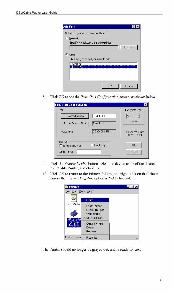
DSL/Cable Router User Guide
80
8. Click OK to see the Print Port Configuration screen, as shown below.
9. Click the Browse Device button, select the device name of the desiredDSL/Cable Router, and click OK.
10. Click OK to return to the Printers folders, and right-click on the Printer.Ensure that the Work off-line option is NOT checked.
The Printer should no longer be grayed out, and is ready for use.
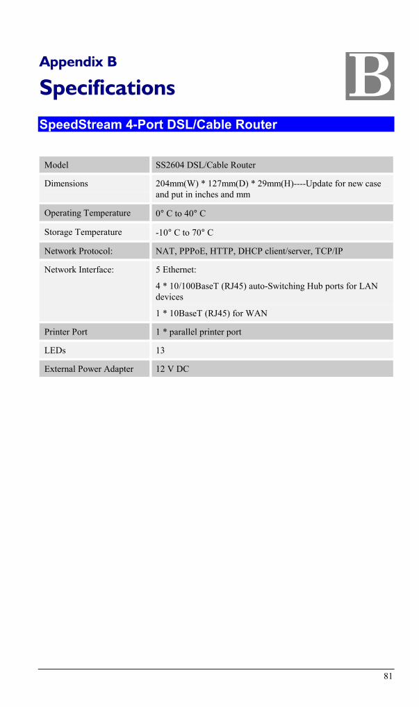
81
Appendix B
Specifications
SpeedStream 4-Port DSL/Cable Router
Model SS2604 DSL/Cable Router
Dimensions 204mm(W) * 127mm(D) * 29mm(H)----Update for new caseand put in inches and mm
Operating Temperature 0° C to 40° C
Storage Temperature -10° C to 70° C
Network Protocol: NAT, PPPoE, HTTP, DHCP client/server, TCP/IP
Network Interface: 5 Ethernet:
4 * 10/100BaseT (RJ45) auto-Switching Hub ports for LANdevices
1 * 10BaseT (RJ45) for WAN
Printer Port 1 * parallel printer port
LEDs 13
External Power Adapter 12 V DC
B

82
Appendix C
Technical SupportBefore contacting technical support, please refer to the previous Troubleshooting information.If you are still unable to resolve the problem, be prepared to provide the following information:
• Model number (SS2604)
• Date of purchase or installation
• Description of problem
SpeedStream Technical Support Services are available 24 hours a day, 7 days a week via theweb, e-mail and telephone.
Visit our website at www.SpeedStream.com for the latest product information and supportknowledge base.
Contact SpeedStream Support via e-mail at: [email protected]
Telephone Support for North America only: 877-823-6722
C


