26W LED WALLPACK INSTALLATION INSTRUCTIONS IMPORTANT READ CAREFULLY BEFORE INSTALLING FIXTURE. RETAIN THESE INSTRUCTIONS FOR FUTURE REFERENCE. RAB fixtures must be wired in accordance with the National Electrical Code and all applicable local codes. Proper grounding is required for safety. THIS PRODUCT MUST BE INSTALLED IN ACCORDANCE WITH THE APPLICABLE INSTALLATION CODE BY A PERSON FAMILIAR WITH THE CONSTRUCTION AND OPERATION OF THE PRODUCT. WARNING: Make certain power is OFF before installing or maintaining fixture. No user serviceable parts inside. Thank you for buying RAB LED lighting. Comments? Call us at 888-RAB-1000, or email: [email protected]JUNCTION BOX MOUNT FOR CONDUIT For use on applications where conduit wiring is needed. 1. Loosen and remove (4) Lens Screws. Remove Door. 2. Loosen and remove (2) Housing Screws. Remove Housing from Back Box. Keep Housing Gasket intact for re-assembly. 3. Secure Back Box to the mounting surface using hardware appropriate for that mounting surface. 4. Wire the fixture using UL listed wire connectors according to NEC and local codes. Apply sealant to all unused conduit entry points. 5. Place Gasket between Back Box and Housing. Re-mount Housing to Back Box. Check Housing Gasket seal all around the Back Box. 6. Re-mount Door to Housing. Tighten (4) Lens Screws. Check door gasket (not shown) seal. 7. Fixture is UL Listed for down and up lighting and may be mounted in either position. Fixture may not melt heavy snow accumulation in an uplight position. CAUTION: For proper weatherproof function all gaskets must be seated properly and all screws inserted and tightened firmly. Lens Screws Junction Box Surface Mount Back Box Housing Gasket Housing Door Housing Screws SURFACE MOUNT FOR RECESSED JUNCTION BOX For use with recessed junction box and wiring. 1. Mount Surface Plate to fixture with (4) Surface Plate Screws. There are two screws from the front and two screws from the back. Make sure Housing Gasket makes complete seal all the way around. 2. Use supplied crossbar. Mount Crossbar to recessed junction box with (2) screws. 3. Place Junction Box Gasket on back of the fixture. Gasket should create seal against mounting surface. 4. Wire fixture to supply wires in recessed junction box according to wiring section. 5. Use 1/4 x 20 stainless steel Mounting Screw to attach fixture to Crossbar. Tighten Mounting Screw. 6. Cover screw with Cap, provided. 7. Fixture is UL Listed for down and up lighting and may be mounted in either position. Fixture may not melt heavy snow accumulation in an uplight position. CAUTION: For proper weatherproof function all gaskets must be seated properly and all screws inserted and tightened firmly. Crossbar Junction Box Gasket Mounting Screw Cap Recessed Junction Box (not provided) Surface Plate Housing Gasket (4) Surface Plate Screws
Transcript
26W LED WALLPACK INSTALLATION INSTRUCTIONS
IMPORTANTREAD CAREFULLY BEFORE INSTALLING FIXTURE. RETAIN THESE INSTRUCTIONS FOR FUTURE REFERENCE.RAB fi xtures must be wired in accordance with the National Electrical Code and all applicable local codes. Proper grounding is required for safety. THIS PRODUCT MUST BE INSTALLED IN ACCORDANCE WITH THE APPLICABLE INSTALLATION CODE BY A PERSON FAMILIAR WITH THE CONSTRUCTION AND OPERATION OF THE PRODUCT. WARNING: Make certain power is OFF before installing or maintaining fi xture. No user serviceable parts inside.
Thank you for buying RAB LED lighting. Comments? Call us at 888-RAB-1000, or email: [email protected]
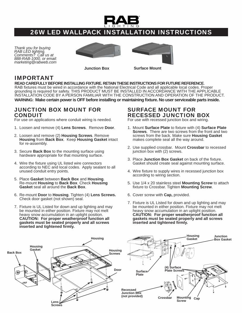
JUNCTION BOX MOUNT FOR CONDUITFor use on applications where conduit wiring is needed.
1. Loosen and remove (4) Lens Screws. Remove Door.
2. Loosen and remove (2) Housing Screws. Remove Housing from Back Box. Keep Housing Gasket intact for re-assembly.
3. Secure Back Box to the mounting surface using hardware appropriate for that mounting surface.
4. Wire the fi xture using UL listed wire connectors according to NEC and local codes. Apply sealant to all unused conduit entry points.
5. Place Gasket between Back Box and Housing. Re-mount Housing to Back Box. Check Housing Gasket seal all around the Back Box.
6. Re-mount Door to Housing. Tighten (4) Lens Screws. Check door gasket (not shown) seal.
7. Fixture is UL Listed for down and up lighting and may be mounted in either position. Fixture may not melt heavy snow accumulation in an uplight position.CAUTION: For proper weatherproof function all gaskets must be seated properly and all screws inserted and tightened fi rmly.
Lens Screws
Junction Box Surface Mount
Back Box
Housing Gasket
Housing
Door
Housing Screws
SURFACE MOUNT FOR RECESSED JUNCTION BOXFor use with recessed junction box and wiring.
1. Mount Surface Plate to fi xture with (4) Surface Plate Screws. There are two screws from the front and two screws from the back. Make sure Housing Gasket makes complete seal all the way around.
2. Use supplied crossbar. Mount Crossbar to recessed junction box with (2) screws.
3. Place Junction Box Gasket on back of the fi xture. Gasket should create seal against mounting surface.
4. Wire fi xture to supply wires in recessed junction box according to wiring section.
5. Use 1/4 x 20 stainless steel Mounting Screw to attach fi xture to Crossbar. Tighten Mounting Screw.
6. Cover screw with Cap, provided.
7. Fixture is UL Listed for down and up lighting and may be mounted in either position. Fixture may not melt heavy snow accumulation in an uplight position.CAUTION: For proper weatherproof function all gaskets must be seated properly and all screws inserted and tightened fi rmly.
Crossbar
Junction Box Gasket
Mounting Screw
Cap
RecessedJunction Box(not provided)
Surface Plate
Housing Gasket
(4) Surface Plate Screws
26W LED WALLPACK INSTALLATION INSTRUCTIONS
TROUBLESHOOTING 1. Check that the line voltage at fi xture is correct. Refer
to wiring directions.
2. Is the fi xture is grounded properly?
3. Is the photocell, if used, functioning properly?
WPLED26-IN-1210
CLEANING & MAINTENANCECAUTION: Be sure fi xture temperature is cool enough to touch. Do not clean or maintain while fi xture is energized.
1. Clean glass lens with non-abrasive glass cleaning solution.
2. Do not open fi xture to clean the LED. Do not touch the LED.
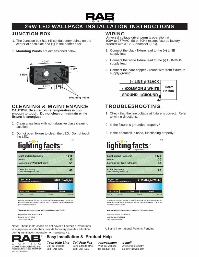
WIRINGUniversal voltage driver permits operation at 100V to 277VAC, 50 or 60Hz except fi xtures factory ordered with a 120V photocell (/PC).
1. Connect the black fi xture lead to the (+) LINE supply lead.
2. Connect the white fi xture lead to the (-) COMMON supply lead.
3. Connect the bare copper Ground wire from fi xture to supply ground.
JUNCTION BOX 1. The Junction box has (4) conduit entry points on the
center of each side and (1) in the center back.
2. Mounting Points are dimensioned below.
US and International Patents Pending
4 3/4”
2 3/16”
3 1/2”
1 1/8”
1 1/8”
Mounting Points
Note: These instructions do not cover all details or variations in equipment nor do they provide for every possible situation during installation, operation or maintenance.
WPLED26 EMERGENCY INSTALLATION SHEET
IMPORTANTREAD CAREFULLY BEFORE INSTALLING FIXTURE. RETAIN THESE INSTRUCTIONS FOR FUTURE REFERENCE. RAB fixtures must be wired in accordance with the National Electrical Code and all applicable local codes. Proper grounding is required for safety. THIS PRODUCT MUST BE INSTALLED IN ACCORDANCE WITH THE APPLICABLE INSTALLATION CODE BY A PERSON FAMILIAR WITH THE CONSTRUCTION AND OPERATION OF THE PRODUCT AND THE HAZARDS INVOLVED. WARNING: Make certain power is OFF and batteries are DISCONNECTED before installing or maintaining fixture. No user serviceable parts inside.
Thank you for buying RAB lighting fixtures. Our goal is to design the best quality products to get the job done right. We’d like to hear your comments. Call the Marketing Department at 888-RAB-1000, or email: [email protected]
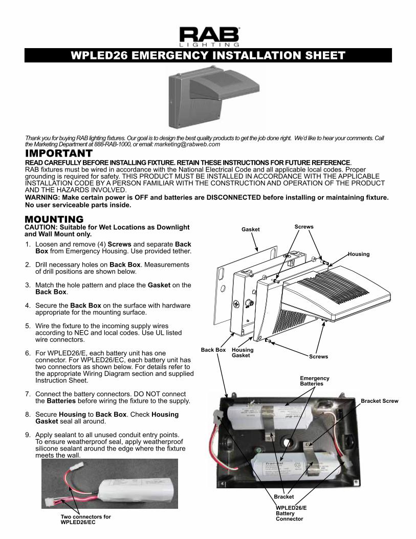
MOuNTINGCAUTION: Suitable for Wet Locations as Downlight and Wall Mount only. 1. Loosen and remove (4) Screws and separate Back
Box from Emergency Housing. Use provided tether.
2. Drill necessary holes on Back Box. Measurements of drill positions are shown below.
3. Match the hole pattern and place the Gasket on the Back Box.
4. Secure the Back Box on the surface with hardware appropriate for the mounting surface.
5. Wire the fixture to the incoming supply wires according to NEC and local codes. Use UL listed wire connectors.
6. For WPLED26/E, each battery unit has one connector. For WPLED26/EC, each battery unit has two connectors as shown below. For details refer to the appropriate Wiring Diagram section and supplied Instruction Sheet.
7. Connect the battery connectors. DO NOT connect the Batteries before wiring the fixture to the supply.
8. Secure Housing to Back Box. Check Housing Gasket seal all around.
9. Apply sealant to all unused conduit entry points.To ensure weatherproof seal, apply weatherproof silicone sealant around the edge where the fixture meets the wall.
Housing
Screws
Bracket Screw
Two connectors for WPLED26/EC
Back Box Housing Gasket
WPLED26/EBatteryConnector
Gasket
Screws
Bracket
EmergencyBatteries
WPLED26 EMERGENCY INSTALLATION SHEET
CLEANING & MAINTENANCE CAUTION: Be sure fixture temperature is cool enough to touch. Do not clean or maintain while fixture is energized.
2. Do not open fixture to clean the LED. Do not touch the LED.
US: Pat. D634,873; CN: ZL 201030129137.X; MX: 32491; TW: D139540; CA: D RAB Lighting Inc. Patent Pending.
Note: These instructions do not cover all details or variations in equipment nor do they provide for every possible situation during installation, operation or maintenance.
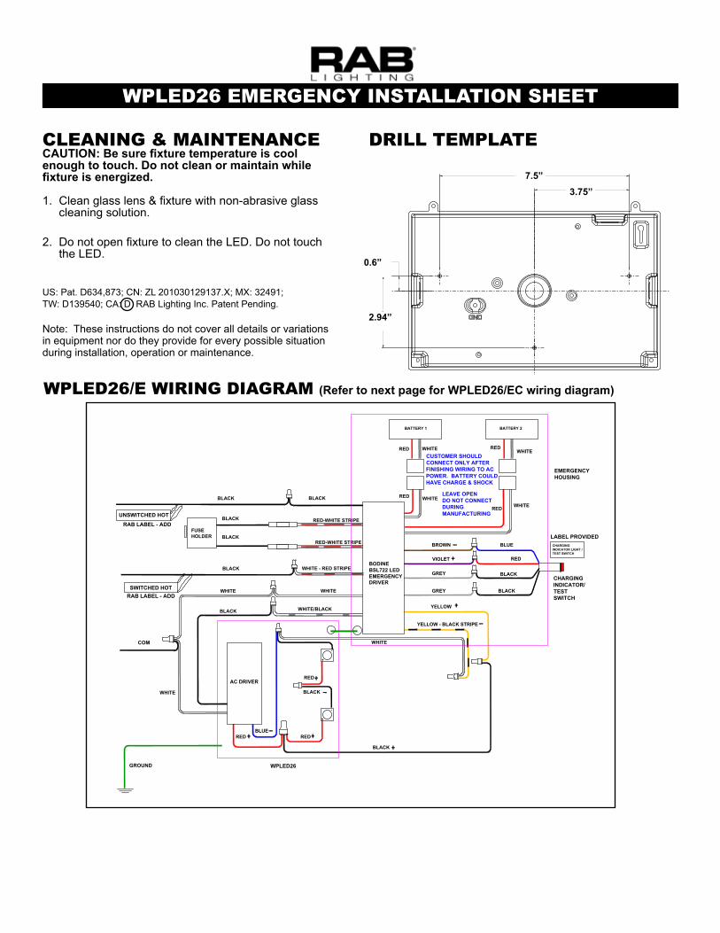
AC DRIVER
COM
GROUND
BODINEBSL722 LEDEMERGENCYDRIVER
BATTERY 1
LEAVE OPENDO NOT CONNECTDURINGMANUFACTURING
CUSTOMER SHOULDCONNECT ONLY AFTERFINISHING WIRING TO ACPOWER. BATTERY COULDHAVE CHARGE & SHOCK
RED-WHITE STRIPE
RED
FUSEHOLDER
CHARGINGINDICATOR LIGHT /TEST SWITCH
BLUE
WHITE
YELLOW
YELLOW - BLACK STRIPE
WPLED26
UNSWITCHED HOT
CHARGINGINDICATOR/TESTSWITCH
BLACK
WHITE
WHITE/BLACK
VIOLET
BROWN
BLACK
RED-WHITE STRIPE BLUE
BLACK
BLACKGREY
GREY
WHITE
WHITE
WHITE
WHITE
WHITE - RED STRIPE
WHITE
BLACK
WHITE
BLACK
BLACK
BLACK
BLACK
SWITCHED HOTRAB LABEL - ADD
RAB LABEL - ADD
LABEL PROVIDED
BATTERY 2
EMERGENCYHOUSING
RED
RED
RED
RED
RED
REDRED
BLACK
WPLED26/E WIRING DIAGRAM (Refer to next page for WPLED26/EC wiring diagram)
2.940[74,68]
7.500[190,5]
.600[15,24]
3.750[95,25]
DRILL TEMPLATE
7.5”3.75”
0.6”
2.94”
WPLED26 EMERGENCY INSTALLATION SHEET
WPLED26 (2X13)EMERGENCY 120V OR277VWIRING DIAGRAM
4.18.12
LED 26W EMERGY COLD120V OR 277V WIRING
KS
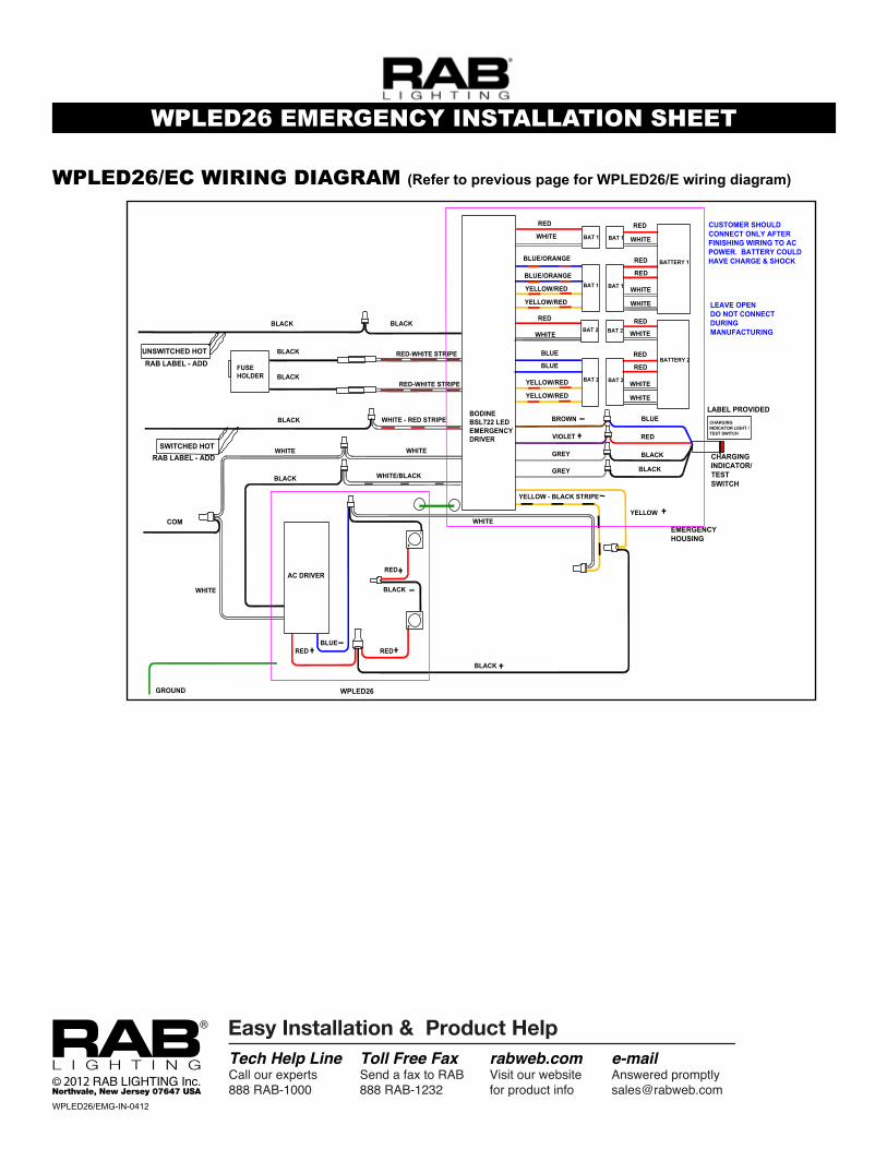
AC DRIVER
COM
GROUND
BODINEBSL722 LEDEMERGENCYDRIVER
BATTERY 1
LEAVE OPENDO NOT CONNECTDURINGMANUFACTURING
CUSTOMER SHOULDCONNECT ONLY AFTERFINISHING WIRING TO ACPOWER. BATTERY COULDHAVE CHARGE & SHOCK
RED-WHITE STRIPE
RED
FUSEHOLDER
CHARGINGINDICATOR LIGHT /TEST SWITCH
BLUE
WHITE
YELLOW
YELLOW - BLACK STRIPE
WPLED26
UNSWITCHED HOT
CHARGINGINDICATOR/TESTSWITCH
BLACK
WHITE
WHITE/BLACK
VIOLET
BROWN
BLACK
RED-WHITE STRIPE
BLUE
BLACK
BLACKGREY
GREY
WHITE
YELLOW/RED
WHITE - RED STRIPE
WHITE
BLACK
WHITE
BLACK
BLACK
BLACK
BLACK
SWITCHED HOTRAB LABEL - ADD
RAB LABEL - ADD
LABEL PROVIDED
BATTERY 2
EMERGENCYHOUSING
RED
RED
RED
REDBLUE/ORANGE
RED
BLACK
WHITE
RED
YELLOW/RED
RED
WHITE
WHITE
WHITE
YELLOW/RED
REDBLUE
BLUE
RED
WHITE
RED
YELLOW/RED
RED
WHITE
WHITE
BLUE/ORANGE
BAT 1
BAT 1
BAT 2
BAT 2
BAT 1
BAT 1
BAT 2
BAT 2
WPLED26/EC WIRING DIAGRAM (Refer to previous page for WPLED26/E wiring diagram)