Proceedings of the International Conference on Emerging Trends in Engineering and Management (ICETEM14)
232-239, December, 2014, Ernakulam, India
233
BIDIRECTIONAL FULL-BRIDGE DC-DC CONVERTER
WITH FLYBACK SNUBBER FOR PHOTOVOLTAIC
APPLICATIONS
INDULEKHA SAJEEV1, SHEMI P A
2
1M.Tech, EEE,Sree Narayana Gurukulam College of Engineering,indu 2Asst.prof., EEE,Sree Narayana Gurukulam College of Engineering
ABSTRACT
Application of a bidirectional full bridge DC-DC converter with flyback snubber for photovoltaic cell is
proposed in this paper. Bidirectional converters are important to interface an energy storage device to renewable energy
sources like fuel cell, solar cell etc. Bridge-type bidirectional converters are important for high power applications. In this
paper, a bridge-type bidirectional dc-dc converter with an isolation transformer is used. A snubber circuit is used to
clamp the voltage spike caused by the current difference between the current-fed inductor and leakage inductance of
isolation transformer. It reduces the current flowing through the active switches at the current-fed side. Operational
principle of the proposed converter is described for step up and step down mode. A PV cell is connected in the low
voltage side to get a boosted output that is used to charge a battery. Simulation is done by using MATLAB.
Keywords: Bidirectional Full Bridge Dc-Dc Converter;Flyback Snubber;PV Cell,Step-Down Mode,Step-Up Mode
1. INTRODUCTION
The importance of bidirectional converters are increasing day by day. They are the main part of a system to
interface an energy storage device and renewable energy sources like solar cell. Bridge-type bidirectional converters are
used for high power applications. A dual full-bridge configuration is used for increasing the power level with step-up
circuit in low voltage side and step-down circuit in high voltage side. A bridge type bidirectional dc-dc converter is used
in this paper to step-up voltage from a solar cell and charge a battery.
Isolated bidirectional dual-active-bridge dc-dc converters have many advantages like electrical isolation, high
reliability, bidirectional energy flow etc[1]. Bidirectional dc-dc converters find applications in battery chargers and
dischargers, uninterruptible power supply, hybrid electric vehicles etc [2]
The main interests of this study includes decreasing switching loss and reduction of current stress. To reduce the
voltage spike caused due to the difference between the currents in the inductor and leakage inductance of transformer,
passive and active clamping circuits have been proposed[3][4]. A fly back snubber circuit can be used to clamp the
voltage to a required level [5]. This reduces the current stress on the switches.
2. ISOLATED BIDIRECTIONAL DC-DC CONVERTER WITH FLYBACK SNUBBER
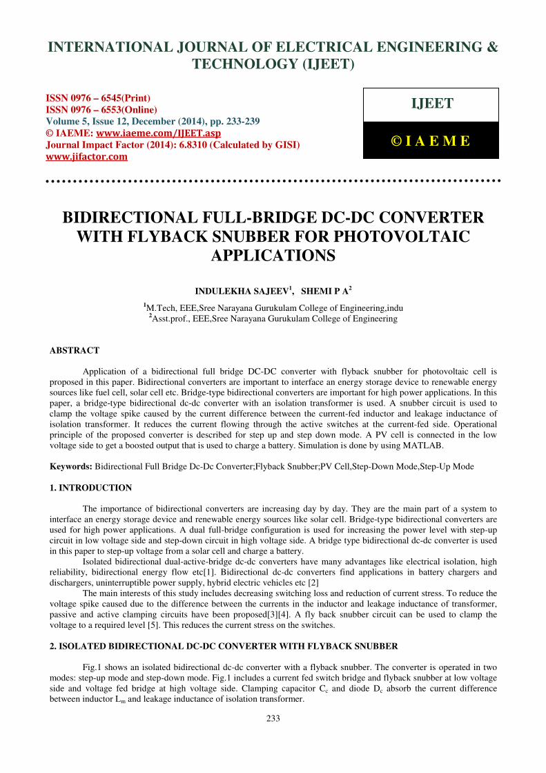
Fig.1 shows an isolated bidirectional dc-dc converter with a flyback snubber. The converter is operated in two
modes: step-up mode and step-down mode. Fig.1 includes a current fed switch bridge and flyback snubber at low voltage
side and voltage fed bridge at high voltage side. Clamping capacitor Cc and diode Dc absorb the current difference
between inductor Lm and leakage inductance of isolation transformer.
INTERNATIONAL JOURNAL OF ELECTRICAL ENGINEERING &
TECHNOLOGY (IJEET)
ISSN 0976 – 6545(Print) ISSN 0976 – 6553(Online) Volume 5, Issue 12, December (2014), pp. 233-239
© IAEME: www.iaeme.com/IJEET.asp Journal Impact Factor (2014): 6.8310 (Calculated by GISI) www.jifactor.com
IJEET
© I A E M E
Proceedings of the International Conference on Emerging Trends in Engineering and Management (ICETEM14)
232-239, December, 2014, Ernakulam, India
234
Voltage stress switches M1-M4 can be limited since the flyback snubber can regulate VC to a desired value
higher than VAB. No spike current circulates through the switches and the voltages across them are clamped. As a result,
reliability of the system is improved.
Assumptions made for the steady state analysis:
1. All components are ideal.
2. Inductor Lm can keep current iL constant for a switching interval.
3. Clamping capacitor Cc is higher than parasitic capacitance of the switches.
Fig.1: isolated bidirectional dc-dc converter with flyback snubber
2.1 Step Up Mode
In this mode, switches M1-M4 are operated and the body diodes of switches M5-M8 conducts for transferring
power to VHV. When switch pair (M1, M4) or (M2,M3) operates, the current difference iC =iL-iP will charge CC to raise iP to
iL. The average power PC transferred to CC is given as:
where:
(2)
VC(R) is regulated VC which is nearly equal to VHV (NP /NS), fs denotes switching frequency and Lm is much
greater than Leq. Power is transferred to the high voltage side through the fly back snubber. The snubber circuit will
regulate the clamping capacitor to VC(R) within one cycle. The peak voltage VC(P) of the clamping capacitor that is
imposed on the low voltage side switches is determined as:
Proceedings of the International Conference on Emerging Trends in Engineering and Management (ICETEM14)
232-239, December, 2014, Ernakulam, India
235
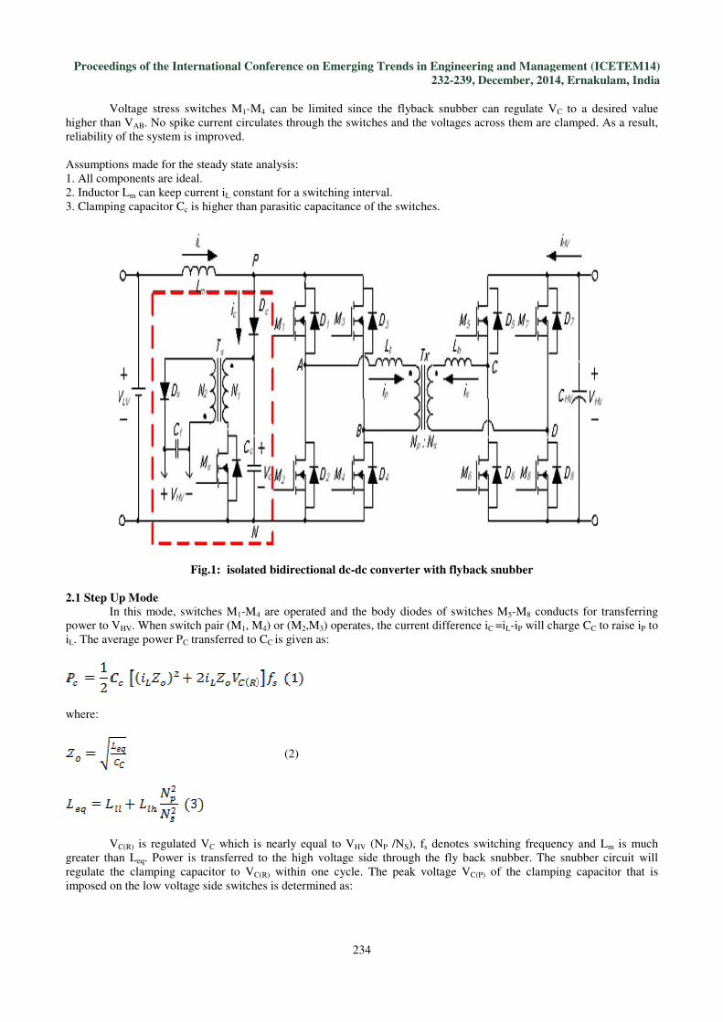
where iL(M) is the maximum inductor current. The operation wave forms of step up mode is shown in Fig 2.
Fig.2:operation wavaforms of step up mode
The different modes of half cycle operation are described below:
Mode 1[t0≤t<t1]:All the switches from M1-M4 are turned on to charge inductor Lm. Inductor current increases linearly.
Equivalent circuit is shown in Fig.3(a).
Mode 2[t1≤t<t2]:At t1, M1 and M4 remain on but M2 and M3 are turned off. Diode Dc conducts till the difference between
iL and ip at t=t2 becomes zero. The body diodes of switches M5 and M8 conduct to transfer power. In this interval, the
current difference flows into Cc. Fig.3(b) shows the equivalent circuit.
Mode 3[t2≤t<t3]:At t2,Dc stops conducting the current difference and the snubber circuit starts its operation. Now the
clamping capacitor Cc discharges and the flyback inductor stores energy.The equivalentcircuit is given in Fig.3(c).
Mode 4[t3≤t<t4]:At t3,energy from the flyback inductor is transferred to the high voltage side. In this intrval,Vc is
regulated to VC(R).Power transfer continues from low voltage side to high voltage side. Fig. 3(d) shows the equivalent
circuit.
Mode 5[t4≤t<t5]: At t4, the capacitor voltage is regulated and snubber remains idle. Power is still transferred which stops
at t5. The equivalent circuit is shown in Fig. 3(e)
Proceedings of the International Conference on Emerging Trends in Engineering and Management (ICETEM14)
232-239, December, 2014, Ernakulam, India
236
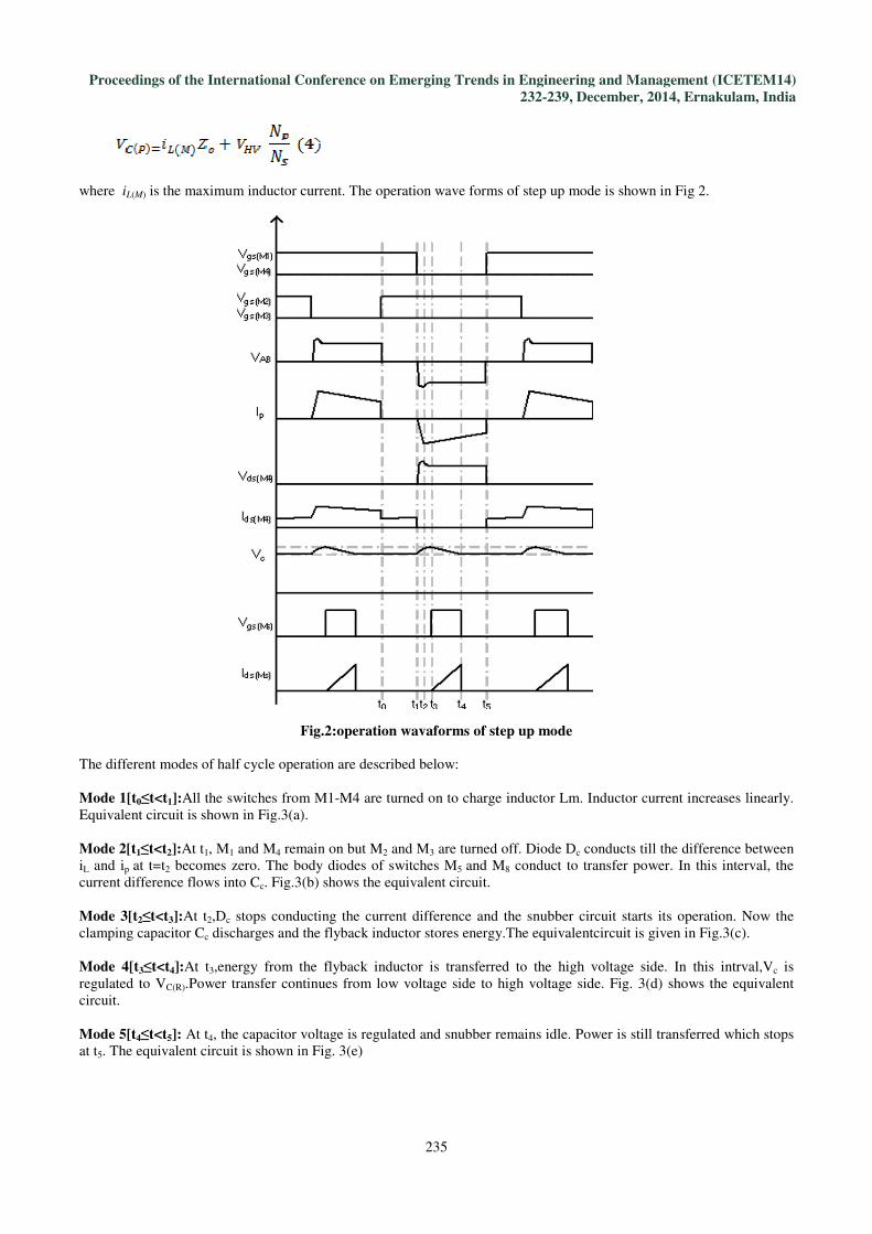
Fig.3:modes of operation of step up mode.(a) mode 1,(b) mode 2, (3)mode3, (4) mode 4, (5)mode 5.
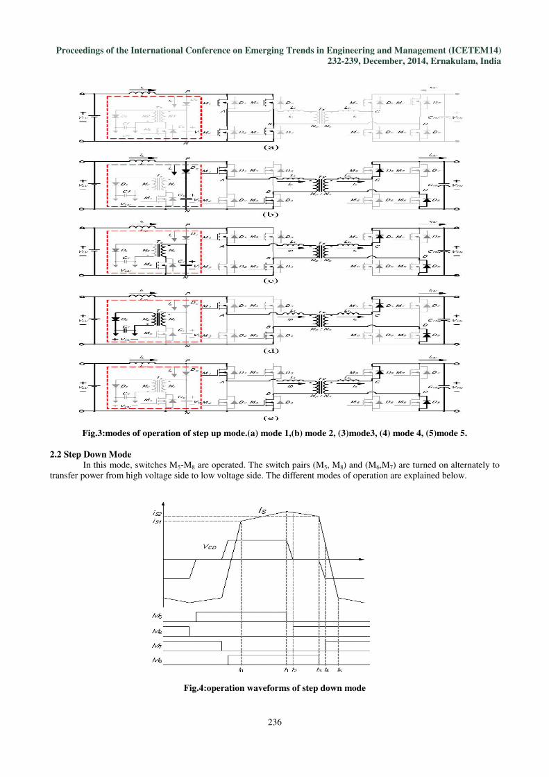
2.2 Step Down Mode
In this mode, switches M5-M8 are operated. The switch pairs (M5, M8) and (M6,M7) are turned on alternately to
transfer power from high voltage side to low voltage side. The different modes of operation are explained below.
Fig.4:operation waveforms of step down mode
Proceedings of the International Conference on Emerging Trends in Engineering and Management (ICETEM14)
232-239, December, 2014, Ernakulam, India
237
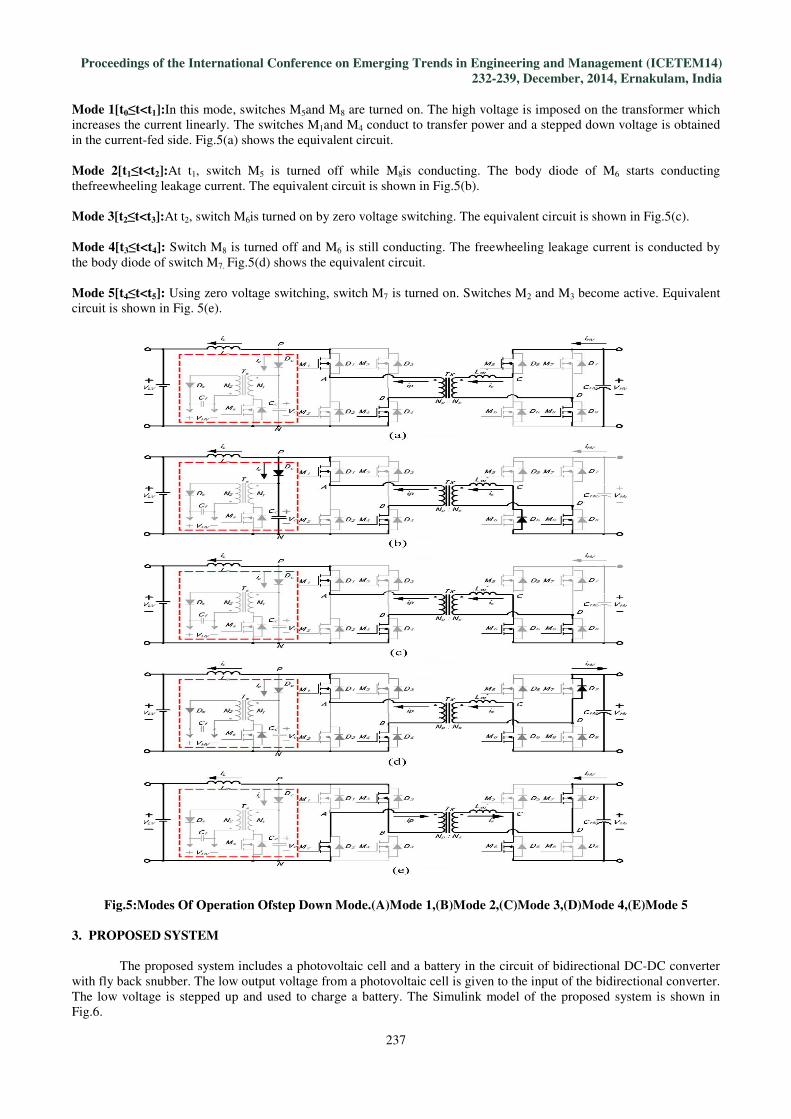
Mode 1[t0≤t<t1]:In this mode, switches M5and M8 are turned on. The high voltage is imposed on the transformer which
increases the current linearly. The switches M1and M4 conduct to transfer power and a stepped down voltage is obtained
in the current-fed side. Fig.5(a) shows the equivalent circuit.
Mode 2[t1≤t<t2]:At t1, switch M5 is turned off while M8is conducting. The body diode of M6 starts conducting
thefreewheeling leakage current. The equivalent circuit is shown in Fig.5(b).
Mode 3[t2≤t<t3]:At t2, switch M6is turned on by zero voltage switching. The equivalent circuit is shown in Fig.5(c).
Mode 4[t3≤t<t4]: Switch M8 is turned off and M6 is still conducting. The freewheeling leakage current is conducted by
the body diode of switch M7. Fig.5(d) shows the equivalent circuit.
Mode 5[t4≤t<t5]: Using zero voltage switching, switch M7 is turned on. Switches M2 and M3 become active. Equivalent
circuit is shown in Fig. 5(e).
Fig.5:Modes Of Operation Ofstep Down Mode.(A)Mode 1,(B)Mode 2,(C)Mode 3,(D)Mode 4,(E)Mode 5
3. PROPOSED SYSTEM
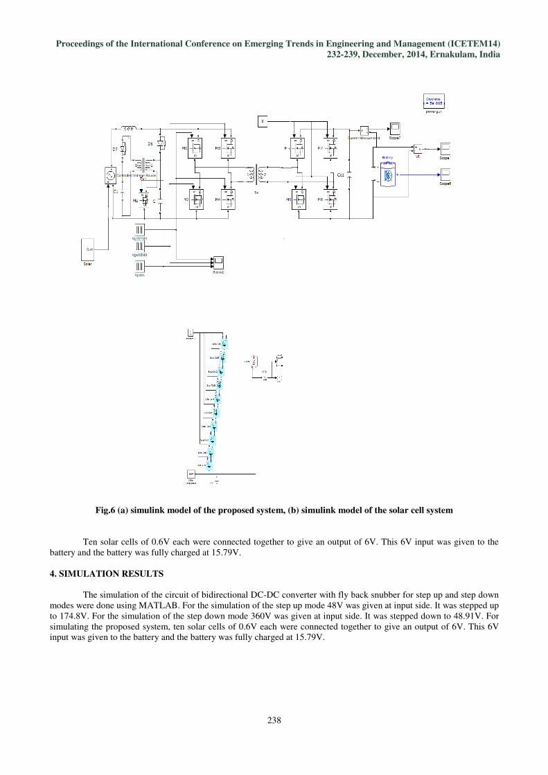
The proposed system includes a photovoltaic cell and a battery in the circuit of bidirectional DC-DC converter
with fly back snubber. The low output voltage from a photovoltaic cell is given to the input of the bidirectional converter.
The low voltage is stepped up and used to charge a battery. The Simulink model of the proposed system is shown in
Fig.6.
Proceedings of the International Conference on Emerging Trends in Engineering and Management (ICETEM14)
232-239, December, 2014, Ernakulam, India
238
Fig.6 (a) simulink model of the proposed system, (b) simulink model of the solar cell system
Ten solar cells of 0.6V each were connected together to give an output of 6V. This 6V input was given to the
battery and the battery was fully charged at 15.79V.
4. SIMULATION RESULTS
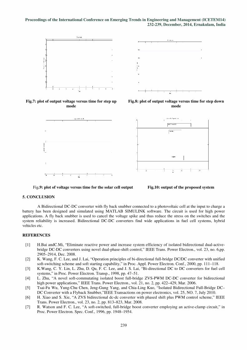
The simulation of the circuit of bidirectional DC-DC converter with fly back snubber for step up and step down
modes were done using MATLAB. For the simulation of the step up mode 48V was given at input side. It was stepped up
to 174.8V. For the simulation of the step down mode 360V was given at input side. It was stepped down to 48.91V. For
simulating the proposed system, ten solar cells of 0.6V each were connected together to give an output of 6V. This 6V
input was given to the battery and the battery was fully charged at 15.79V.
Proceedings of the International Conference on Emerging Trends in Engineering and Management (ICETEM14)
232-239, December, 2014, Ernakulam, India
239
Fig.7: plot of output voltage versus time for step up
mode
Fig.8: plot of output voltage versus time for step down
mode
Fig.9: plot of voltage versus time for the solar cell output Fig.10: output of the proposed system
5. CONCLUSION
A Bidirectional DC-DC converter with fly back snubber connected to a photovoltaic cell at the input to charge a
battery has been designed and simulated using MATLAB SIMULINK software. The circuit is used for high power
applications. A fly back snubber is used to cancel the voltage spike and thus reduce the stress on the switches and the
system reliability is increased. Bidirectional DC-DC converters find wide applications in fuel cell systems, hybrid
vehicles etc.
REFERENCES
[1] H.Bai andC.Mi, “Eliminate reactive power and increase system efficiency of isolated bidirectional dual-active-
bridge DC-DC converters using novel dual-phase-shift control,” IEEE Trans. Power Electron., vol. 23, no. 6,pp.
2905–2914, Dec. 2008.
[2] K. Wang, F. C. Lee, and J. Lai, “Operation principles of bi-directional full-bridge DC/DC converter with unified
soft-switching scheme and soft starting capability,” in Proc. Appl. Power Electron. Conf., 2000, pp. 111–118.
[3] K.Wang, C. Y. Lin, L. Zhu, D. Qu, F. C. Lee, and J. S. Lai, “Bi-directional DC to DC converters for fuel cell
systems,” in Proc. Power Electron. Transp., 1998, pp. 47–51.
[4] L. Zhu, “A novel soft-commutating isolated boost full-bridge ZVS-PWM DC-DC converter for bidirectional
high power applications,” IEEE Trans. Power Electron., vol. 21, no. 2, pp. 422–429, Mar. 2006.
[5] Tsai-Fu Wu, Yung-Chu Chen, Jeng-Gung Yang, and Chia-Ling Kuo, “Isolated Bidirectional Full-Bridge DC–
DC Converter with a Flyback Snubber,”IEEE Transactions on power electronics, vol. 25, NO. 7, July 2010.
[6] H. Xiao and S. Xie, “A ZVS bidirectional dc-dc converter with phased shift plus PWM control scheme,” IEEE
Trans. Power Electron., vol. 23, no. 2, pp. 813–823, Mar. 2008.
[7] R. Watson and F. C. Lee, “A soft-switched, full-bridge boost converter employing an active-clamp circuit,” in
Proc. Power Electron. Spec. Conf., 1996, pp. 1948–1954.