128


28X_EN.indd 2 2015/02/27 13:42

▋Contents▊▊ Introduction
Features 1-1SafetyInformation 1-2
▊▊General▊InformationIntroductiontotheTransmitter 2-1Antenna 2-1Sticklengthadjustment 2-1Neckstrapattachment 2-1Cleaningthetransmitterandscreen 2-1Turningthetransmitteron 2-1Warningdisplay 2-1Unlockingthescreen 2-2TransmitterLED’s 2-2Shuttingdownthetransmitter 2-2InsertingandremovingtheSDcard 2-2USBports,headphonejack,trainerjack,chargejack 2-2Insertingandremovingthetransmitterbatteries 2-3Chargingthetransmitterbatteries 2-3Voiceprompts 2-428channels–upto14msrefreshrates 2-4RG712BXreceiver 2-4Stickmode 2-4
Stickspringtensionandtraveladjustment 2-6
▊▊Functions▊Common▊to▊All▊ModelsInstallingthestickverticalanglecontrolblocks 3-1Changingthestickhorizontalanglecontrolblocks 3-2Removingandinstallingthestickswitch 3-2Operatingthestickswitch 3-3Receiverconnections 3-4Listofreceiverconnectingchannels 3-5Installingtelemetrysensors 3-5
2.4GHzRFcharacteristics 3-5Receiverantennaconsiderations 3-6
Bindingprocedure 3-7Rangecheck 3-7DMSSEZBINDsystem 3-8TransmitterControls 3-9Namesandfunctionsoftheinputkeys 3-11
HomeScreens 3-11Aboutitemsandwidgets 3-12
Addingitemstothehomescreen 3-13Removingitemsfromthehomescreen 3-13Groupingitems 3-13Submenu(home/applicationselectionscreens) 3-14Wallpaper 3-14Systemsettings 3-14
Mixingcurve 3-15Changingvalues 3-15Whatarethefunctionandsystemlists? 3-16Airplanefunctionandsystemlists 3-16Helicopterfunctionandsystemlists 3-17Gliderfunctionandsystemlists 3-17Other 3-18Widgets 3-18
Newmodelsetup 3-18Airplane 3-18Glider 3-19Helicopter 3-19
Flightmodes 3-20Functionsthatcanbeselectedbyflightmode 3-20Functionsrelevantfordifferentmodeltypes 3-20Displayofthecurrentflightmode 3-20Airplane 3-21
Understandingtheswitchselectionmenus 3-22
▊▊Function▊ListDUALRATE&EXPONENTIAL 4-1TRAVELADJUST 4-4LIMITADJUST 4-5SUBTRIM 4-6REVERSESWITCH 4-7SERVOSPEED 4-8THROTTLECURVE 4-9PITCHCURVE 4-11THROTTLEHOLD 4-13GYROSENSITIVITY 4-15GOVERNOR 4-18SWASHMIX 4-19THROTRIM 4-21
28X_EN.indd 1 2015/02/27 13:42

THROTTLEMIX 4-23FLAPSYSTEM 4-24SNAPROLL 4-25DIFFERENTIAL 4-26AILERONTORUDDERMIX 4-28AILERONTOFLAPMIX 4-29ELEVATORTOFLAPMIX 4-31RUDDERTOAILERON/ELEVATORMIX 4-33GEARCONTROL 4-35OUTPUTCURVE 4-36FLAPRATE 4-37MOTORSYSTEM 4-39CAMBERSYSTEM 4-40BRAKESYSTEM 4-41FLAPERONMIX 4-44ELEVATORTOCAMBERMIX 4-46RUDDERTOSPOILERMIX 4-47PROGRAMMIXING[PROG.MIX1-10] 4-49TIMER 4-53MONITOR 4-55
▊▊System▊ListMODELSELECT 5-1TYPESELECT 5-3FLIGHTMODESETUP 5-3FLIGHTMODEDELAY 5-5TRIMSYSTEM 5-5ANALOGUEPOSITIONSWITCH 5-7TRIMINPUTSWITCH 5-8STICKALERT 5-9WARNING 5-9TRANSMITTERSETTING 5-10TRAINERSYSTEM 5-11BIND&RANGECHECK 5-13FAILSAFE 5-14CHANNELSETTINGS 5-15SWASHTYPE 5-16WINGTYPE 5-17HARDWARESETTING 5-19
STICKACCELERATOR 5-20ALLSERVOHOLD 5-21XBUSFUNCTIONS 5-22
▊▊Telemetry▊System▊ 6-1
▊▊Other▊Android▊FunctionsBrowser 7-1Calculator 7-1Downloads 7-1Gallery 7-1Music 7-2OIfilemanager 7-2Setting 7-2
▊▊WidgetsTransmitterbatteryvoltage 8-1Timer 8-1Music 8-1Musicplaylist 8-2Photogallery 8-2Trimpositionindicator 8-2Flightmodeindicator 8-2Telemetryreceivervoltage 8-2Telemetrytemperature 8-2Telemetryrpm 8-2Telemetryaltitude 8-2Telemetryairspeed 8-2Telemetrycurrent 8-2Telemetryvariometer 8-2Telemetryvoltage 8-2
▊▊Other▊InformationRepairandAfterSalesService 9-1FCCandICInformation 9-1Precautions 9-1
28X_EN.indd 2 2015/02/27 13:42

1-1
Introduction
▋FeaturesYour new 28X is one of the finest model aircraft transmitters ever created. It sets a new benchmark in performance and ergonomics. In order to make full use of the features of this radio and to safely enjoy your RC activities, please carefully read this operation manual.
Integrated touch screen android interfaceThe 28X is the first RC system to offer an Android operating system. This technology is accessible through a 480 x 273 pixel, 4.3" WQVGA-TFT full-color touch screen. The transmitter is equipped with dual processors to allow for smooth interfacing and reliable radio frequency output. The user interface is also customizable, so you can change the wallpaper and color schemes to suit your preferences. There is 4GB of internal memory with 512MB RAM 28 channels – up to 14ms refresh rates!The transmitter is configured for sixteen 14ms channels. If you require more than 16 channels, you can choose to add four (56ms) channels at a time, in place of one 14ms channel. So the final 28 channels are in a configuration of twelve 14ms channels, and sixteen 56ms channels. Note all the channels are proportional, and you are unlikely to notice a difference in response between the 14ms and 56ms channels. CNC aluminum ball-bearing supported gimbalsThe 28X stick units have 65,536 step stick resolution, which is 16 times more precise than any other RC transmitter. The CNC machined aluminum gimbals are supported by ball bearings and can be adjusted to suit any pilot. Customizable audio and vibration alertsAnother great feature of the JR 28X is an audio controller, which you can use for voice, music and telemetry notifications. These audio and vibration notifications can also be customized as you see fit. Custom 28X transmitter case includedThe custom designed transmitter case opens from the top, and provides secure storage for your transmitter. Safety power switch designThe transmitter has been designed with a push button power switch that will prevent accidental powering on and off. You will also notice how the antenna is removable, allowing for safe storage. Aluminum chassisThis JR transmitter is contained within a strong, cast aluminum chassis and comes with an integrated USB host controller and USB device port, allowing for easy data interfacing and PC connection. The radio has an external SD card slot to give you additional storage space for models,
images, sound and telemetry data. JR’s revolutionary DMSS systemThe 28X uses JR's proprietary 2.4GHz DMSS protocol for a super secure RF link. JR’s newly developed DMSS system maintains high speed servo response while allowing simultaneous use of telemetry functions. The high-speed telemetry function allows information from the aircraft (that was previously unknown to the user) to be monitored on the transmitter. In addition, alarms with unique sounds alert the user to the situation on the aircraft without even looking at the screen. Stick dialA stick dial has been added on both sticks. Two additional channels can be assigned to these. Long lasting powerThe JR 28X comes with one 3200mAh Li-Ion battery, and supports an optional second battery for extended operation. The included charger fully charges the transmitter in approximately 3 hours. Multiple flight modesFifteen flight modes are available for each aircraft type (acro/heli/sailplane). Each flight mode can be fully customized. Curve adjustment by trim deviceTrim input switches can be used for adjustment of almost all mixing curves and other functions during flight. The entire curve can be increased/decreased using the trim input switch while the curve shape does not change, or alternatively individual points on a curve can be adjusted during flight. Wing typesMany varied pre-settings help as a wizard during the set-up: 4 flaps, 4 ailerons, 2 spoilers, 4 engines, etc.
NEM-B77A
▋TransmitterspecificationsItem Specification
Part Number: NET-T1128GType of control: 28 channel computer mixing
RF: 2.4GHz
Modulation: DMSS(Dual Modulation Spectrum System)2.4GHz FHSS Spread Spectrum Method
Power source: 7.2V Li-Ion battery x 2 (each 3200mAh2L3200(3200mA) ※ 1 or 2 batteries can be used
Neutral position: 1.5ms
28X_EN.indd 1 2015/02/27 13:42
1-2
Introduction
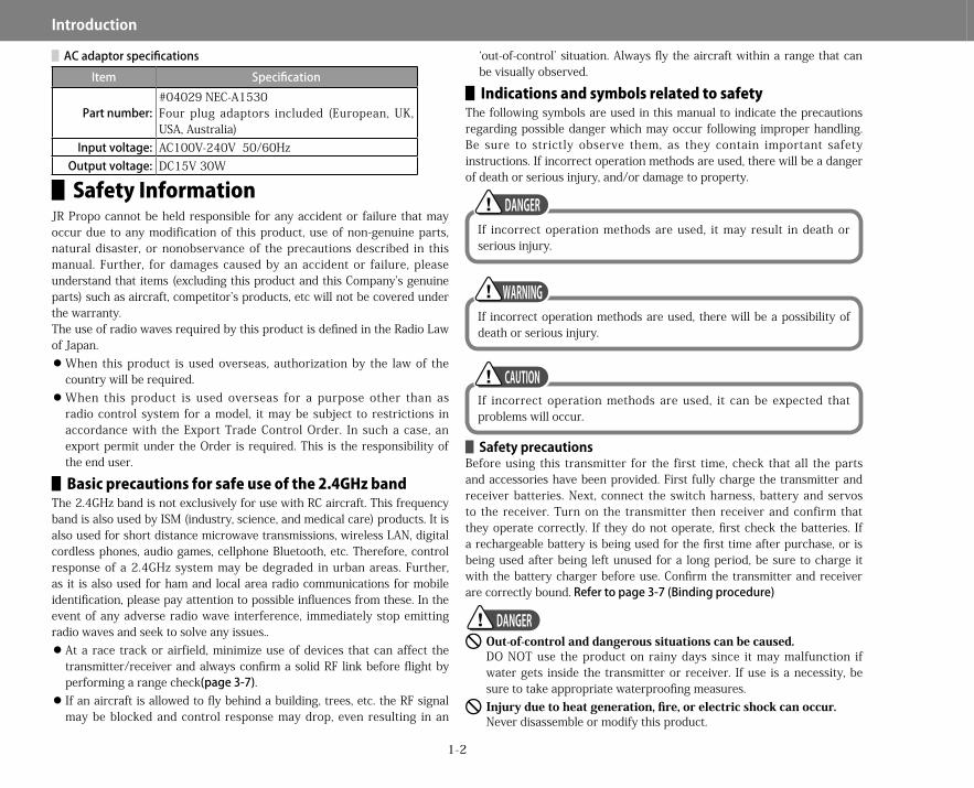
▋Safety InformationJR Propo cannot be held responsible for any accident or failure that may occur due to any modification of this product, use of non-genuine parts, natural disaster, or nonobservance of the precautions described in this manual. Further, for damages caused by an accident or failure, please understand that items (excluding this product and this Company’s genuine parts) such as aircraft, competitor’s products, etc will not be covered under the warranty.The use of radio waves required by this product is defined in the Radio Law of Japan.
When this product is used overseas, authorization by the law of the country will be required. When this product is used overseas for a purpose other than as radio control system for a model, it may be subject to restrictions in accordance with the Export Trade Control Order. In such a case, an export permit under the Order is required. This is the responsibility of the end user.
▋▋Basic▋precautions▋for▋safe▋use▋of▋the▋2.4GHz▋bandThe 2.4GHz band is not exclusively for use with RC aircraft. This frequency band is also used by ISM (industry, science, and medical care) products. It is also used for short distance microwave transmissions, wireless LAN, digital cordless phones, audio games, cellphone Bluetooth, etc. Therefore, control response of a 2.4GHz system may be degraded in urban areas. Further, as it is also used for ham and local area radio communications for mobile identification, please pay attention to possible influences from these. In the event of any adverse radio wave interference, immediately stop emitting radio waves and seek to solve any issues..
At a race track or airfield, minimize use of devices that can affect the transmitter/receiver and always confirm a solid RF link before flight by performing a range check(page3-7). If an aircraft is allowed to fly behind a building, trees, etc. the RF signal may be blocked and control response may drop, even resulting in an
‘out-of-control’ situation. Always fly the aircraft within a range that can be visually observed.
▋▋Indications▋and▋symbols▋related▋to▋safetyThe following symbols are used in this manual to indicate the precautions regarding possible danger which may occur following improper handling. Be sure to strictly observe them, as they contain important safety instructions. If incorrect operation methods are used, there will be a danger of death or serious injury, and/or damage to property.
▋▋Safety▋precautionsBefore using this transmitter for the first time, check that all the parts and accessories have been provided. First fully charge the transmitter and receiver batteries. Next, connect the switch harness, battery and servos to the receiver. Turn on the transmitter then receiver and confirm that they operate correctly. If they do not operate, first check the batteries. If a rechargeable battery is being used for the first time after purchase, or is being used after being left unused for a long period, be sure to charge it with the battery charger before use. Confirm the transmitter and receiver are correctly bound.Refertopage3-7(Bindingprocedure)
�� Out-of-control and dangerous situations can be caused.DO NOT use the product on rainy days since it may malfunction if water gets inside the transmitter or receiver. If use is a necessity, be sure to take appropriate waterproofing measures.�� Injury due to heat generation, fire, or electric shock can occur.Never disassemble or modify this product.
▋ACadaptorspecificationsItem Specification
Part number: #04029 NEC-A1530Four plug adaptors included (European, UK, USA, Australia)
Input voltage: AC100V-240V 50/60HzOutput voltage: DC15V 30W
If incorrect operation methods are used, it may result in death or serious injury.
DANGER
If incorrect operation methods are used, there will be a possibility of death or serious injury.
WARNING
If incorrect operation methods are used, it can be expected that problems will occur.
CAUTION
DANGER
28X_EN.indd 2 2015/02/27 13:42
1-3
Introduction
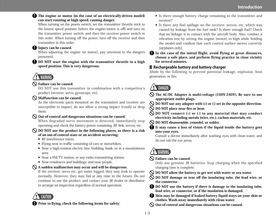
�� The engine or motor (in the case of an electrically-driven model) can start rotating at high speed, causing danger.When turning on the power switch, set the transmitter throttle stick to the lowest speed position (where the engine/motor is off) and turn on the transmitter power switch, and then the receiver power switch in this order. When turning off the power, turn off the receiver and then transmitter in this order.�� Injury can be caused.When adjusting the engine (or motor), pay attention to the dangers presented.�� DO NOT start the engine with the transmitter throttle in a high speed position. This is very dangerous.
�� Failure can be caused.DO NOT use this transmitter in combination with a competitor’s product (receiver, servo, gyroscope, etc).�� Malfunction can be caused.As the electronic parts mounted on the transmitter and receiver are susceptible to impact, do not allow a strong impact (crash) or drop them.�� Out-of-control and dangerous situations can be caused.When degraded servo movement is detected, immediately stop operating and check the battery power remaining, RF link, servos, etc.�� DO NOT use the product in the following places, as there is a risk of an out-of-control state or an accident occurring:��RF interference exists.��Flying near to traffic consisting of cars or motorbikes.��Near a high-tension electric line, building, bank, or in a mountainous area.��Near a FM/TV station, or any radio transmitting station.��Near residences and buildings, and near people.
�� A sudden malfunction may occur and will be dangerous.If the receiver, servo etc. get water logged, they may look to operate normally. However, they may fail at any time in the future. Do not continue to use the product, and contact your JR dealer or distributor to arrange an inspection regardless of normal operation.
�� Prior to flying, check the following items for safety:
��Is there enough battery charge remaining in the transmitter and receiver?��Is there any fuel spillage on the receiver, servos, etc. which was caused by leakage from the fuel tank? Is there enough fuel? Check that no linkage is in contact with the aircraft body. Also, conduct a vibration test by setting the engine (motor) to high while holding the model and confirm that each control surface moves correctly (airplanes only).
�� In the case of the initial flight, avoid flying at great distances, choose a safe place, and perform flying practice in close vicinity for several minutes.▋▋Rechargeable▋battery▋and▋battery▋charger
Abide by the following to prevent potential leakage, explosion, heat generation, or fire.
�� The AC/DC Adapter is multi-voltage (100V-240V). Be sure to use appropriate outlet plugs.�� DO NOT use any adapter with (+) or (-) set in the opposite direction.�� DO NOT place near fire or heat.�� DO NOT connect (+) or (-) to any material that may conduct electricity including metals (wire, etc.), carbon materials, etc.�� DO NOT disassemble, remodel, or solder.�� It may cause a loss of vision if the liquid inside the battery gets into your eyes.Consult a doctor immediately after washing eyes with clean water, and do not rub the eye areas.
�� Failure can be caused.Only use genuine JR batteries. Stop charging when the specified charging time is complete.�� DO NOT allow the battery to get wet with water or sea water.�� DO NOT damage or tear off the insulating tube, the lead wire, or the connector.�� DO NOT use the battery if there is damage to the insulating tube, lead wire, or connector, or if the insulation is damaged.�� Skin may be damaged if leaked battery liquid stays on your skin or clothes. Wash away immediately with clean water.�� Out-of-control and dangerous situations can be caused.
WARNING
CAUTION
DANGER
WARNING
28X_EN.indd 3 2015/02/27 13:42

1-4
Introduction
The rechargeable battery is composed several individual batteries. Note that the actual battery level cannot be precisely confirmed by testers such as a battery checker. Check the state of charge in a comprehensive way by using a battery checker, checking the recharge time, and operating time.
�� Do not store the battery in a place with high temperature/humidity or dust.�� Store the battery out of reach of children. �� Do not charge the battery in a place with low temperature (below zero degrees Celsius).�� Dispose of old batteries according to the local disposal regulations - do not throw them away in garbage cans, etc.▋▋Recycling▋rechargeable▋batteries
Used Li-Ion batteries are important resources. Place a piece of tape or similar over the terminal areas, and drop them off to recycling depots that collect small rechargeable batteries.
CAUTION
28X_EN.indd 4 2015/02/27 13:42

2-1
General▋Information
▋Introduction to the TransmitterYour new JR 28X will provide years of reliable service. To get the best performance from your new transmitter, please be sure to fully understand all its controls and functions. Reading this manual will help greatly with this task.
▋▋AntennaAlways have the antenna installed when using the transmitter. Tighten the antenna with your hand to prevent it from loosening. Confirm it is tight before flight.
▋▋Color▋touch▋screenThe 28X features an all new color touch screen. This is used to quickly program even very complex functions within the radio. The screen should only be operated using light finger pressure. Never use a sharp object such as a pen, etc to press on the screen.
▋▋Switch▋identificationIf you look closely at the transmitter, you will see that each switch is labeled with a letter (A, B, C, etc), as are the various digital auxiliary controls (page3-9).
▋▋Stick▋length▋adjustmentUndo the recessed set screw located at the tip of the control stick. Now rotate the entire stick to adjust its length. When finished, lock the recessed set screw.
▋▋Neck▋strap▋attachmentFor added comfort and stability during use, you may choose to use a neck strap.
▋▋Cleaning▋the▋transmitter▋and▋screenYour transmitter and screen can be cleaned using a soft cloth – ideally a microfiber cloth, as sold for cleaning eyewear. Never use solvents or detergents when cleaning your transmitter.
▋▋Turning▋the▋transmitter▋onTo turn the transmitter on, briefly press the power button located on the face of the transmitter. The first time the transmitter is turned on for a day’s flying, the boot time is approximately 30 seconds.
▋▋Warning▋displayIf the transmitter is turned on and the transmitter stick or other switches are in incorrect positions, a warning tone is generated and the following screen appears.The stick position or switch(s) creating the warning are identified on this screen. Simply move the controls to the correct position to cancel the warning.You can customize the warnings for each model by setting the warning parameters in the warning menu seepage5-9.This menu can be accessed directly from the warning display.
Lock
Unlock
ロック
ロック解除
Flight mode switch(location depends on selected model)
Throttle stick
28X_EN.indd 1 2015/02/27 13:42
2-2
General▋Information
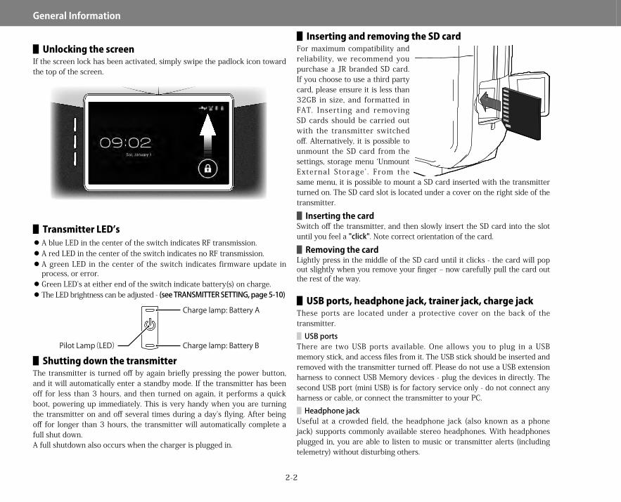
▋▋Unlocking▋the▋screenIf the screen lock has been activated, simply swipe the padlock icon toward the top of the screen.
▋▋Transmitter▋LED’s A blue LED in the center of the switch indicates RF transmission. A red LED in the center of the switch indicates no RF transmission. A green LED in the center of the switch indicates firmware update in process, or error. Green LED’s at either end of the switch indicate battery(s) on charge. The LED brightness can be adjusted - (seeTRANSMITTERSETTING,page5-10)
▋▋Shutting▋down▋the▋transmitterThe transmitter is turned off by again briefly pressing the power button, and it will automatically enter a standby mode. If the transmitter has been off for less than 3 hours, and then turned on again, it performs a quick boot, powering up immediately. This is very handy when you are turning the transmitter on and off several times during a day’s flying. After being off for longer than 3 hours, the transmitter will automatically complete a full shut down.A full shutdown also occurs when the charger is plugged in.
▋▋Inserting▋and▋removing▋the▋SD▋cardFor maximum compatibility and reliability, we recommend you purchase a JR branded SD card. If you choose to use a third party card, please ensure it is less than 32GB in size, and formatted in FAT. Inserting and removing SD cards should be carried out with the transmitter switched off. Alternatively, it is possible to unmount the SD card from the settings, storage menu ‘Unmount External Storage’ . From the same menu, it is possible to mount a SD card inserted with the transmitter turned on. The SD card slot is located under a cover on the right side of the transmitter.▋▋Inserting▋the▋card
Switch off the transmitter, and then slowly insert the SD card into the slot until you feel a "click". Note correct orientation of the card.▋▋Removing▋the▋card
Lightly press in the middle of the SD card until it clicks - the card will pop out slightly when you remove your finger – now carefully pull the card out the rest of the way.
▋▋USB▋ports,▋headphone▋jack,▋trainer▋jack,▋charge▋jackThese ports are located under a protective cover on the back of the transmitter.
▋USBportsThere are two USB ports available. One allows you to plug in a USB memory stick, and access files from it. The USB stick should be inserted and removed with the transmitter turned off. Please do not use a USB extension harness to connect USB Memory devices - plug the devices in directly. The second USB port (mini USB) is for factory service only - do not connect any harness or cable, or connect the transmitter to your PC.
▋HeadphonejackUseful at a crowded field, the headphone jack (also known as a phone jack) supports commonly available stereo headphones. With headphones plugged in, you are able to listen to music or transmitter alerts (including telemetry) without disturbing others.
Pilot Lamp(LED)
Charge lamp: Battery A
Charge lamp: Battery B
28X_EN.indd 2 2015/02/27 13:42

2-3
General▋Information
▋TrainerjackThe 3.5mm mono trainer jack is accessible here to allow flight training to take place. Please see page 5-11 for information regarding the trainer system.
▋ChargejackThe charge jack is conveniently located under this cover. Please refer to page2-3 for information on charging the transmitter.
▋▋Inserting▋and▋removing▋the▋transmitter▋batteries
①Always ensure the transmitter is turned off before removing the batteries.
②Slide the battery cover latch on the rear of the transmitter to the right. The battery cover can now be carefully opened.
③The batteries can now be removed. Be careful to press the lever lock before removing the battery power lead. The battery temperature lead can be carefully pulled straight out.
④When fitting new batteries, be sure to only use JR genuine replacement Li-Ion packs designed for the 28X. Carefully fit the battery power connector and temperature sensor lead. Ensure that the battery power and temperature leads are correctly plugged into their corresponding sockets. When closing the battery cover, be careful not to pinch any wires, and ensure the latch engages fully.
▋▋Charging▋the▋transmitter▋batteriesThe transmitter operates exclusively using genuine JR Li-Ion batteries. One battery is supplied, and a second may be purchased as an optional extra for extended operation. If using one battery, it can be in either the upper or lower battery location. Do not use the transmitter with other rechargeable batteries or with dry cell batteries. The temperature sensor lead must remain connected for charging to be successful. During charging, the transmitter should be switched off. When the transmitter is on, charging will not take place.※ Note that if using a flight simulator with the control cable plugged
into the trainer jack (and the power switch off on the transmitter), it is possible to plug the charge cable into the transmitter and use the power adaptor to supply power. Since the built-in battery will not be used, this will allow extended simulator time while not running down the transmitter battery packs. However, the internal batteries will not charge with the trainer lead plugged in.
①Insert the power adaptor into an AC electric power socket.②Insert the plug of the adaptor as far as it will go into the DC power jack
of the transmitter. The DC power jack is located under a cover on the rear of the transmitter.
③Either one or two green LED’s will illuminate at the top and bottom of the switch. These represent the one or two batteries installed in the transmitter. If the appropriate number of LED’s do not illuminate, an error may have occurred. In this situation, detach the power adapter plug, and re-insert it. If the LED(s) do not light even after the cable has been removed and inserted several times, please contact your JR agent or distributor in your country.
④During charging, the LED(s) will remain illuminated. When charging
A
B
2L3200
A
B
2L3200
A
B
2L3200
A
B
2L3200
28X_EN.indd 3 2015/02/27 13:42
2-4
General▋Information
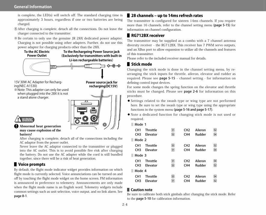
is complete, the LED(s) will switch off. The standard charging time is approximately 3 hours, regardless if one or two batteries are being charged.
⑤After charging is complete, detach all the connections. Do not leave the charger connected to the transmitter.
※ Be certain to only use the genuine JR 28X dedicated power adapter. Charging is not possible using other adapters. Further, do not use this power adapter for charging products other than the 28X.
�� Abnormal heat generation may cause explosion of the battery!After charging is complete, detach all of the connections including the AC adaptor from the power outlet.Never leave the AC adaptor connected to the transmitter or plugged into the AC outlet. This is to avoid possible fire risk after charging the battery. Do not use the AC adapter while the cord is still bundled together, since there will be a risk of heat generation.
▋▋Voice▋promptsBy default, the flight mode indicator widget provides information on which flight mode is currently selected. Voice annunciations can be turned on and off by touching the flight mode widget on the home screen. FM information is announced in preference to telemetry. Announcements are only made when the flight mode name is an English word. Telemetry widgets include common settings such as unit selection, voice output, and no link alarm. See page8-1.
▋▋28▋channels▋–▋up▋to▋14ms▋refresh▋ratesThe transmitter is configured for sixteen 14ms channels. If you require more than 16 channels, refer to the channel setting menu (page5-15) for information on channel configuration.
▋▋RG712BX▋receiverThe transmitter may be supplied as a combo with a 7 channel antenna diversity receiver – the RG712BX. This receiver has 7 PWM servo outputs, and an XBus port to allow expansion to utilize all the channels and features of this transmitter.Please refer to the included receiver manual for details.
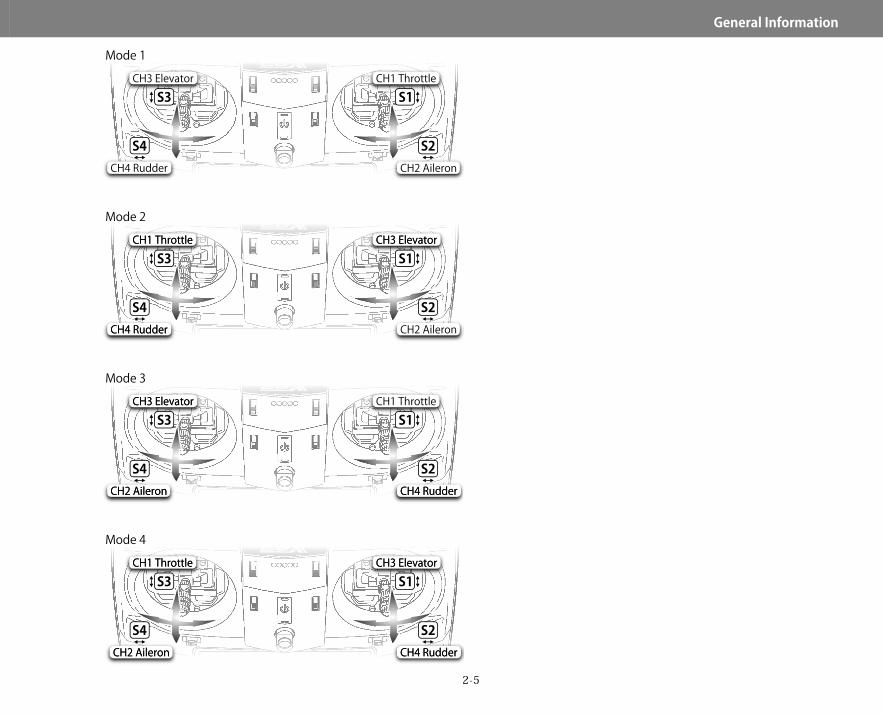
▋▋Stick▋modeChanging the stick mode is done in the channel setting menu, by re-arranging the stick inputs for throttle, aileron, elevator and rudder as required. Please see page5-15 – channel setting - for information on defining control input devices.For some mode changes the spring function on the elevator and throttle sticks must be changed. Please see page2-6 for information on this procedure.
Settings related to the swash type or wing type are not performed here. Be sure to set the swash type or wing type using the appropriate functions in the system menu (page5-16andpage5-17). Note a dedicated function for changing stick mode is not used or required.
▋Mode 1CH1 Throttle S1 CH2 Aileron S2
CH3 Elevator S3 CH4 Rudder S4
▋Mode 2CH1 Throttle S3 CH2 Aileron S2
CH3 Elevator S1 CH4 Rudder S4
▋Mode 3CH1 Throttle S1 CH2 Aileron S4
CH3 Elevator S3 CH4 Rudder S2
▋Mode 4CH1 Throttle S3 CH2 Aileron S4
CH3 Elevator S1 CH4 Rudder S2
▋▋Caution▋noteBe sure to calibrate both stick gimbals after changing the stick mode. Refer to the page5-10 for calibration information.
Power source jack for recharging(DC15V)
To the AC Electric Power Outlet
To the Rechargeing Power Source jack(Exclusively for transmitters with built-in
Li-ion rechargeable batteries)
15V 30W AC Adapter for Recharg-ing(NEC-A1530)※ Note: This adapter can only be used
when plugged into the 28X it is not a stand alone charger.
WARNING
28X_EN.indd 4 2015/02/27 13:42
2-5
General▋Information
S3
S4
S1
S2
Mode 1CH1 Throttle
CH2 Aileron
CH3 Elevator
CH4 Rudder
S3
S4
S1
S2
Mode 2CH3 ElevatorCH3 Elevator
CH2 Aileron
CH1 ThrottleCH1 Throttle
CH4 RudderCH4 Rudder
S3
S4
S1
S2
Mode 3CH1 Throttle
CH4 Rudder CH4 Rudder
CH3 ElevatorCH3 Elevator
CH2 AileronCH2 Aileron
S3
S4
S1
S2
Mode 4CH3 ElevatorCH3 Elevator
CH4 Rudder CH4 Rudder
CH1 ThrottleCH1 Throttle
CH2 Aileron CH2 Aileron
28X_EN.indd 5 2015/02/27 13:42
2-6
General▋Information
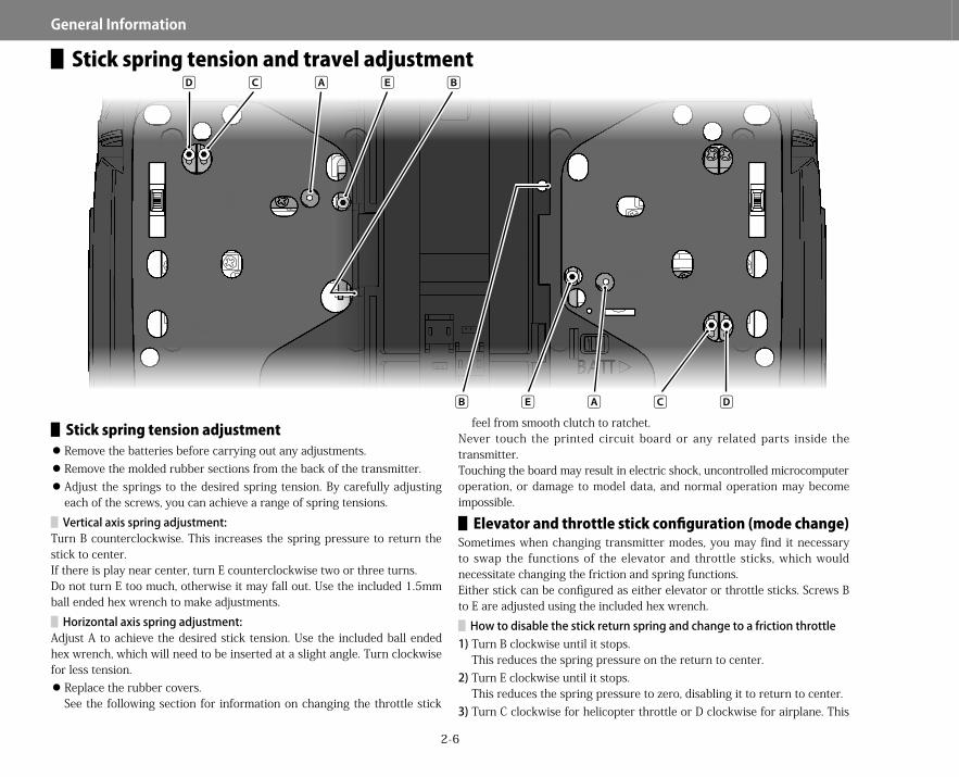
▋Stick spring tension and travel adjustment
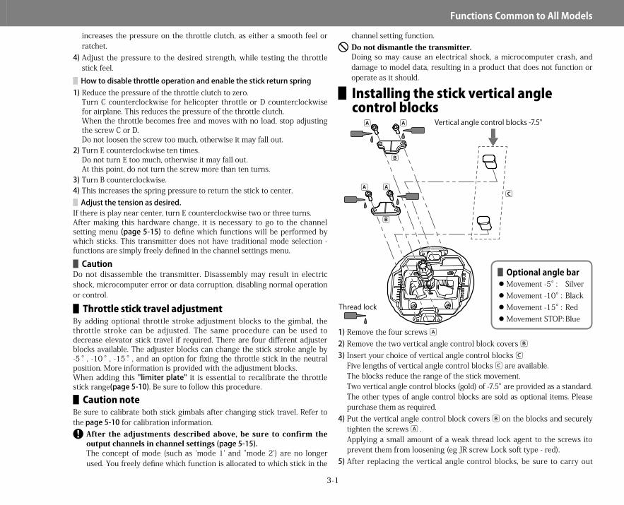
▋▋Stick▋spring▋tension▋adjustment Remove the batteries before carrying out any adjustments. Remove the molded rubber sections from the back of the transmitter. Adjust the springs to the desired spring tension. By carefully adjusting each of the screws, you can achieve a range of spring tensions.▋Verticalaxisspringadjustment:
Turn B counterclockwise. This increases the spring pressure to return the stick to center.If there is play near center, turn E counterclockwise two or three turns.Do not turn E too much, otherwise it may fall out. Use the included 1.5mm ball ended hex wrench to make adjustments.
▋Horizontalaxisspringadjustment:Adjust A to achieve the desired stick tension. Use the included ball ended hex wrench, which will need to be inserted at a slight angle. Turn clockwise for less tension.
Replace the rubber covers.See the following section for information on changing the throttle stick
feel from smooth clutch to ratchet.Never touch the printed circuit board or any related parts inside the transmitter.Touching the board may result in electric shock, uncontrolled microcomputer operation, or damage to model data, and normal operation may become impossible.
▋▋Elevator▋and▋throttle▋stick▋configuration▋(mode▋change)Sometimes when changing transmitter modes, you may find it necessary to swap the functions of the elevator and throttle sticks, which would necessitate changing the friction and spring functions.Either stick can be configured as either elevator or throttle sticks. Screws B to E are adjusted using the included hex wrench.
▋Howtodisablethestickreturnspringandchangetoafrictionthrottle1)Turn B clockwise until it stops.
This reduces the spring pressure on the return to center. 2)Turn E clockwise until it stops.
This reduces the spring pressure to zero, disabling it to return to center. 3)Turn C clockwise for helicopter throttle or D clockwise for airplane. This
A BED C
AB E DC
28X_EN.indd 6 2015/02/27 13:42
3-1
Functions▋Common▋to▋All▋Models
increases the pressure on the throttle clutch, as either a smooth feel or ratchet.
4)Adjust the pressure to the desired strength, while testing the throttle stick feel.▋Howtodisablethrottleoperationandenablethestickreturnspring
1)Reduce the pressure of the throttle clutch to zero.Turn C counterclockwise for helicopter throttle or D counterclockwise for airplane. This reduces the pressure of the throttle clutch.When the throttle becomes free and moves with no load, stop adjusting the screw C or D.Do not loosen the screw too much, otherwise it may fall out.
2)Turn E counterclockwise ten times.Do not turn E too much, otherwise it may fall out.At this point, do not turn the screw more than ten turns.
3)Turn B counterclockwise. 4)This increases the spring pressure to return the stick to center.
▋Adjustthetensionasdesired.If there is play near center, turn E counterclockwise two or three turns.After making this hardware change, it is necessary to go to the channel setting menu (page5-15) to define which functions will be performed by which sticks. This transmitter does not have traditional mode selection - functions are simply freely defined in the channel settings menu.▋▋Caution
Do not disassemble the transmitter. Disassembly may result in electric shock, microcomputer error or data corruption, disabling normal operation or control.
▋▋Throttle▋stick▋travel▋adjustmentBy adding optional throttle stroke adjustment blocks to the gimbal, the throttle stroke can be adjusted. The same procedure can be used to decrease elevator stick travel if required. There are four different adjuster blocks available. The adjuster blocks can change the stick stroke angle by -5 °, -10 °, -15 °, and an option for fixing the throttle stick in the neutral position. More information is provided with the adjustment blocks.When adding this "limiterplate" it is essential to recalibrate the throttle stick range(page5-10). Be sure to follow this procedure.▋▋Caution▋note
Be sure to calibrate both stick gimbals after changing stick travel. Refer to thepage5-10 for calibration information.�� After the adjustments described above, be sure to confirm the output channels in channel settings (page5-15).The concept of mode (such as 'mode 1' and ”mode 2') are no longer used. You freely define which function is allocated to which stick in the
channel setting function.�� Do not dismantle the transmitter.Doing so may cause an electrical shock, a microcomputer crash, and damage to model data, resulting in a product that does not function or operate as it should.
▋Installing the stick vertical angle control blocks
1)Remove the four screws A2)Remove the two vertical angle control block covers B3)Insert your choice of vertical angle control blocks C
Five lengths of vertical angle control blocks C are available.The blocks reduce the range of the stick movement.Two vertical angle control blocks (gold) of -7.5° are provided as a standard. The other types of angle control blocks are sold as optional items. Please purchase them as required.
4)Put the vertical angle control block covers B on the blocks and securely tighten the screws A .Applying a small amount of a weak thread lock agent to the screws ito prevent them from loosening (eg JR screw Lock soft type - red).
5)After replacing the vertical angle control blocks, be sure to carry out
B
C
B
Vertical angle control blocks -7.5°AA
A A
Thread lock
▋▋Optional▋angle▋bar Movement -5°: Silver Movement -10°: Black Movement -15°: Red Movement STOP: Blue
28X_EN.indd 1 2015/02/27 13:42
3-2
Functions▋Common▋to▋All▋Models
stick calibration (seepage5-10).※ When turning on the transmitter, a warning may be issued after
replacing the blocks. To release the warning status, display the warning screen, touch "setting", and increase the numeric value for the position of the throttle stick.
※ After carrying out stick calibration, be sure to return the warning value to the original setting (page5-9).
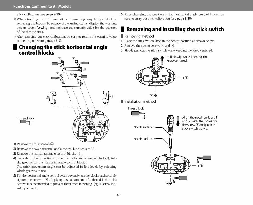
▋Changing the stick horizontal angle control blocks
1)Remove the four screws A .2)Remove the two horizontal angle control block covers B .3)Remove the horizontal angle control blocks C .4)Securely fit the projections of the horizontal angle control blocks C into
the grooves for the horizontal angle control blocks.The stick movement angle can be adjusted in five levels by selecting which grooves to use.
5)Put the horizontal angle control block covers B on the blocks and securely tighten the screws A . Applying a small amount of a thread lock to the screws is recommended to prevent them from loosening (eg JR screw lock soft type - red).
6)After changing the position of the horizontal angle control blocks, be sure to carry out stick calibration (seepage5-10).
▋Removing and installing the stick switch▋▋Removing▋method
1)Place the stick switch knob in the center position as shown below.2)Remove the socket screws A and B .3)Slowly pull out the stick switch while keeping the knob centered.
▋▋Installation▋method
Thread lock
A
C C
A
A AB
B
A
B
Pull slowly while keeping the knob centered
A
B
Notch surface 1
Notch surface 2
Align the notch surfaces 1 and 2 with the holes for the screw A and push the stick switch slowly.
Thread lock
28X_EN.indd 2 2015/02/27 13:42

3-3
Functions▋Common▋to▋All▋Models
1)Insert the stick switch while keeping the notch surface 1 and the notch surface 2 aligned with the hole for the socket screw A .Forcefully pushing the stick switch may cause damage to the equipment.When the stick switch cannot be inserted easily, check the positions of the notches and screw hole and try to insert it again instead of pushing forcefully.Confirm that the stick switch is fully inserted.
2)Look through the hole of the socket screw A to check that the notch surface 1 is in line with the hole.Be sure to tighten socket screw A first.Confirm that the socket screw A is tightened, and then tighten the socket screw B .Be careful not to install the socket screws in the wrong order. If doing so, the center position cannot be set securely.Applying a small amount of a thread lock to the screws to prevent them from loosening (eg JR screw lock soft type -red).
3)Confirm that the stick switch knob moves smoothly. seepage5-10 for information on calibrating the stick switch.
▋▋Removing▋and▋installing▋the▋stick▋head▋for▋the▋stick▋switch Remove the socket screw. Unscrew the stick head to remove. When installing the stick head, screw on till a slight gap of about 0.5mm remains between the stick head and the knob of the stick switch main body. Securely fix the socket screw. Confirm that the stick switch knob turns smoothly.
▋Operating the stick switchThe stick switch knob can be turned as shown below.Channels or control functions can be assigned to the switch.
-5°-5° StandardStandard -10°-10° -15°-15°Fixed
(no horizontal stick movement)
Grooves for fitting the horizontal angle control blocksProjections for fitting
Stick switch main body
Stick headGap of about 0.5mm
Socket screw
28X_EN.indd 3 2015/02/27 13:42

3-4
Functions▋Common▋to▋All▋Models
▋Receiver connections▋▋Receiver▋connections▋to▋the▋servos▋and▋the▋power▋supply
The channels on the receiver are labeled with names rather than numbers. These will not always match the names of the required functions, depending on how you have configured the transmitter.
With reference to the transmitter monitor (page4-55) and channel setting (page5-15)screens, it is easy to confirm the output position of each servo.
If using more than 7 channels, optional XBus servos or XBus to PWM converter harnesses make expansion easy. Please refer to XBus information on the JR website.
Since all receivers are sensitive to vibration, shock, and water, anti-vibration and waterproofing measures should be implemented as necessary.
If the connectors become detached while flying, there will be a risk of the model crashing. Please securely insert all connectors as far as they will go.
If extension leads are used during installation, sticky tape should be wrapped round the connectors to secure them, or commercially available safety clips used. Be absolutely sure not to leave the connectors hanging unsupported.
▋▋Connections▋to▋the▋receiverThe connections to the receiver vary widely depending on your model setup. The monitor screen (page4-55) and channel setting menu (page5-15) can be used to help identify exact servo connections. Always carefully check each function and switch before flying.
▋▋About▋XBus The XBus system employs a serial data transmission method with products supporting XBus instead of control using PWM signals which have conventionally been employed for radio controlled aircraft. The XBus signals contain all channels. Each device selects data that is assigned to it and respond according to the data. Before connecting XBus products, carry out channel assignment using the transmitter or other devices. Otherwise, the devices will not respond to the signals. Do not directly connect conventional PWM devices to the XBus output. Doing so may result in damage. The power supply can be separated using an optional JR XBus hub for separate power supply.
※ *We recommend using a remote antenna when the receiver is mounted on an aircraft where signal reception conditions are poor, such as one made of carbon.
※ When using a remote antenna, be sure to carry out the binding process with the remote antenna connected.
RG712BX Receiver
Receiver Battery(sold separately)
SENSORSensor(sold separately)Connection
Diagram
Switch Harness(sold separately)
When inserting the connectors, take note of the correct direction.
Close up of the connector
Sensor Connections
When connecting sensors, use a Y-Harness (sold separately) connected to the [BIND/BAT-T/SENS] terminal.
* It is not necessary to carry out binding for the sensor.
Conventional servo(sold separately)
X.Bus system products
Remote antenna(sold separately)
Y-Harness(sold separately)
RX
wiring example
Conventional Servo
X.Bus Compatible servo
BATTRY
BATTRY
HUB HUBOutput Port
(1ch)
(2ch)
(3ch) (4ch)
(5ch)
(6ch)
Servos can be operated from a separate power supply by using the optional 'X-Bus power hub'.
※
X.Bus Compatible servo
X.Bus Compatible servoX.Bus Compatible servo
X.Bus Compatible servo
XBus PWM Converter
28X_EN.indd 4 2015/02/27 13:42

3-5
Functions▋Common▋to▋All▋Models
▋▋List▋of▋receiver▋connecting▋channels
▋▋Installing▋telemetry▋sensorsIf installing two or more telemetry sensors, be sure to use the telemetry sensor adapter shown below.
※ It is not necessary to bind the telemetry sensors.
▋2.4GHz RF characteristicsThe 2.4GHz band radio waves are very directional. The receiver signal is very dependent on the direction of the transmitter and receiver antenna. Since the antenna receives radio waves from the sides rather than from the tip, please appropriately position the receiver antenna when installing the receiver in the model.▋▋Transmitter▋antenna▋orientation
Because the strongest radio wave radiate from the sides of the antenna, this orientation allows the best transmission to the receiver and provides the safest operation.
As strong radio waves radiate from the sides of the antenna, this orientation provides the best transmission to the receiver for those who fly helicopters or airplanes. It is also the suggested orientation for those pilots who hold the radio horizontally.
This position provides the best signal to the receiver for those who fly gliders and also those pilots who hold the transmitter vertically to the aircraft.
Receiver Helicopter Airplane Glider1)THRO THRO THRO LAIL
2)AILE AILE AILE RAIL
3)ELEV ELEV ELEV ELEV
4)RUDD RUDD RUDD RUDD
5)GEAR GYRO1 GEAR1 AUX05
6)AUX1 PIT. FLAP FLAP
7)AUX2 AUX07 AUX07 SPOI
TLS1-ADPTelemetrySensorAdapterPartnumber:03439
S
SS
SS
W
28X_EN.indd 5 2015/02/27 13:42
3-6
Functions▋Common▋to▋All▋Models
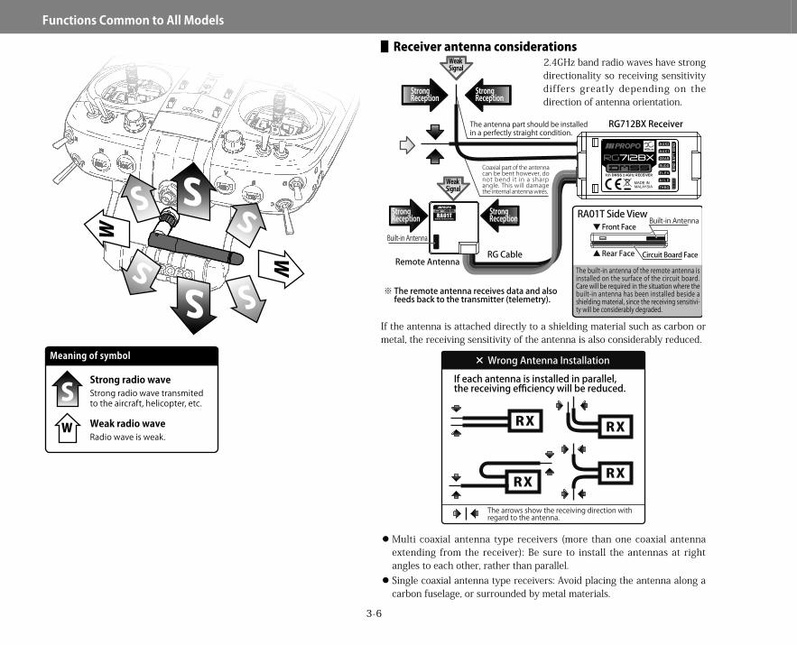
▋▋Receiver▋antenna▋considerations2.4GHz band radio waves have strong directionality so receiving sensitivity differs greatly depending on the direction of antenna orientation.
If the antenna is attached directly to a shielding material such as carbon or metal, the receiving sensitivity of the antenna is also considerably reduced.
Multi coaxial antenna type receivers (more than one coaxial antenna extending from the receiver): Be sure to install the antennas at right angles to each other, rather than parallel. Single coaxial antenna type receivers: Avoid placing the antenna along a carbon fuselage, or surrounded by metal materials.
Meaning of symbol
SW
Strong radio wave transmited to the aircraft, helicopter, etc.
Strong radio wave
Radio wave is weak.Weak radio wave
StrongReception
WeakSignal
StrongReception
Coaxial part of the antenna can be bent however, do not bend it in a sharp angle. This will damage the internal antenna wires.
The antenna part should be installed in a perfectly straight condition.
RG Cable
※ The remote antenna receives data and also feeds back to the transmitter (telemetry).
Remote Antenna
Built-in Antenna▼ Front Face
▲ Rear Face
StrongReception
WeakSignal
StrongReception RA01T Side View
Built-in Antenna
Circuit Board Face
RG712BX Receiver
The built-in antenna of the remote antenna is installed on the surface of the circuit board. Care will be required in the situation where the built-in antenna has been installed beside a shielding material, since the receiving sensitivi-ty will be considerably degraded.
RX
RX
RX
RX
× Wrong Antenna Installation
If each antenna is installed in parallel, the receiving efficiency will be reduced.
The arrows show the receiving direction with regard to the antenna.
28X_EN.indd 6 2015/02/27 13:42
3-7
Functions▋Common▋to▋All▋Models
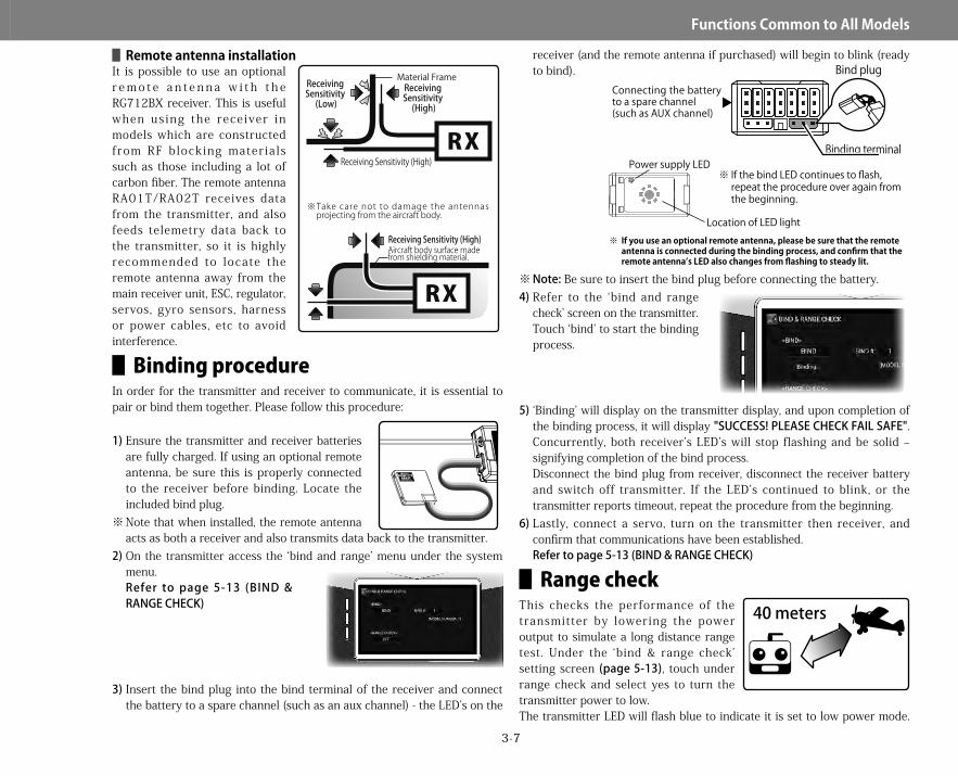
▋▋Remote▋antenna▋installationIt is possible to use an optional r e m o t e a n t e n n a w i t h t h e RG712BX receiver. This is useful when us ing the rece iver in models which are constructed from RF blocking materia ls such as those including a lot of carbon fiber. The remote antenna RA01T/RA02T receives data from the transmitter, and also feeds telemetry data back to the transmitter, so it is highly recommended to locate the remote antenna away from the main receiver unit, ESC, regulator, servos, gyro sensors, harness or power cables, etc to avoid interference.
▋Binding procedureIn order for the transmitter and receiver to communicate, it is essential to pair or bind them together. Please follow this procedure:
1)Ensure the transmitter and receiver batteries are fully charged. If using an optional remote antenna, be sure this is properly connected to the receiver before binding. Locate the included bind plug.
※ Note that when installed, the remote antenna acts as both a receiver and also transmits data back to the transmitter.
2)On the transmitter access the ‘bind and range’ menu under the system menu.Refer to page 5-13 (BIND&RANGECHECK)
3)Insert the bind plug into the bind terminal of the receiver and connect the battery to a spare channel (such as an aux channel) - the LED’s on the
receiver (and the remote antenna if purchased) will begin to blink (ready to bind).
※ Note: Be sure to insert the bind plug before connecting the battery.4)Refer to the ‘bind and range
check’ screen on the transmitter. Touch ‘bind’ to start the binding process.
5)‘Binding’ will display on the transmitter display, and upon completion of the binding process, it will display "SUCCESS!PLEASECHECKFAILSAFE". Concurrently, both receiver’s LED’s will stop flashing and be solid – signifying completion of the bind process.Disconnect the bind plug from receiver, disconnect the receiver battery and switch off transmitter. If the LED’s continued to blink, or the transmitter reports timeout, repeat the procedure from the beginning.
6)Lastly, connect a servo, turn on the transmitter then receiver, and confirm that communications have been established.Refertopage5-13(BIND&RANGECHECK)
▋Range checkThis checks the performance of the transmitter by lowering the power output to simulate a long distance range test. Under the ‘bind & range check’ setting screen (page5-13), touch under range check and select yes to turn the transmitter power to low.The transmitter LED will flash blue to indicate it is set to low power mode.
Receiving Sensitivity (High)RX
RX
Receiving Sensitivity
(Low)
Material FrameReceiving Sensitivity
(High)
Receiving Sensitivity (High)
※Take care not to damage the antennas projecting from the aircraft body.
Aircraft body surface made from shielding material.
Location of LED light
※ If the bind LED continues to flash, repeat the procedure over again from the beginning.
※ If you use an optional remote antenna, please be sure that the remote antenna is connected during the binding process, and confirm that the remote antenna’s LED also changes from flashing to steady lit.
Power supply LED
Bind plugConnecting the battery to a spare channel(such as AUX channel)
Binding terminal
40 meters
28X_EN.indd 7 2015/02/27 13:42

3-8
Functions▋Common▋to▋All▋Models
When in this mode, walk a distance of approximately 40m from the aircraft and confirm that the transmitter operates the aircraft normally. Continue testing as you walk around the aircraft. Touch under range check again and confirm yes to return the transmitter to standard transmission power.
Besurethatthefailsafesettingsaresetinthetransmitter (page5-14).
Please note that when the model or model type is changed in the transmitter, re-binding will be required. Never fly the aircraft in range check mode.
▋DMSS EZ BIND system ▋▋EZ▋BIND▋system
The EZ BIND system is a unique system designed for park flyer receivers. With the EZ BIND system, binding can be carried out without using a binding plug.▋▋If▋the▋power▋supply▋for▋the▋receiver▋is▋switched▋on▋prior▋to▋the▋transmitter▋after▋binding
I f the power supply for the receiver is switched on prior to the transmitter after the bind process is completed, the receiver enters a bind standby state in [3 seconds]. The bind standby lasts in [5 seconds].If the transmitter for which the receiver is bound is switched on, communication will immediately start.If the transmitter is changed, communication will not be performed. Be sure to carry out the bind process again.
▋▋Binding▋methodTo establish communication with a transmitter, binding (pairing) must be carried out. Here, the bind method is described.1)Display "BIND&RANGECHECK" in the system list of the transmitter.(see
BIND&RANGECHECK,page5-13)2)Touch on 'bind'. 'Binding...' will be displayed and the bind process will
begin.The transmitter will remain in bind mode for approximately 20 seconds.
3)While the transmitter is in bind mode, switch on the receiver. The LED will start flashing, and it will automatically bind to the transmitter.When the LED light changes from flashing to solid on, the bind process is complete.If the bind LED continues flashing, repeat the procedure again from the beginning.
4)Finally, connect the servos and confirm they work as expected.When conducting a range test, place the aircraft approximately 40 meters from the transmitter, and select low power output mode in the transmitter. Walk around the aircraft, and check that the aircraft can be operated from any position.seepage5-13(BIND&RANGECHECK).
Be sure to configure the failsafe settings after the bind process.
After the bind process, configure the failsafe settings by using the failsafe function of the transmitter and confirm that the failsafe properly works.
1. Are the transmitter and receiver batteries fully charged?2. Is the remote antenna securely connected? 3. Is the distance between the transmitter and receiver too close?4. When the procedure is carried out on the top of a desk or bench top that is
made from metal, the binding procedure may not be successful.
If the bind process or range check is not successful, check the following items:
CAUTION Location of LED light
40 meters
In normal use, be sure to turn on the transmitter before the receiver.
Turning on the transmitter first ensures the receiver does not enter ez-bind mode. If the receiver happens to enter this mode, it could become bound to another transmitter if it was close by in bind mode.
28X_EN.indd 8 2015/02/27 13:42
3-9
Functions▋Common▋to▋All▋Models
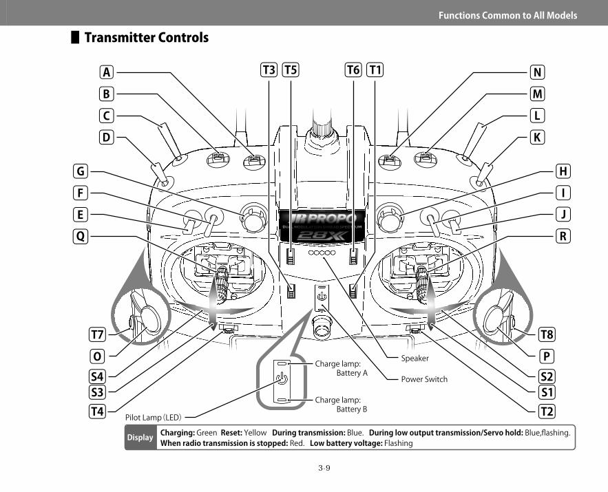
▋Transmitter Controls
Speaker
Power Switch
A
RQ
N
M
HG
B
T8T7
T5
C
F
O
D
S3S4
T4
E
T3 T6
K
S1S2
L
J
I
P
T1
T2
Display
Pilot Lamp(LED)
Charging: Green Reset: Yellow During transmission: Blue. During low output transmission/Servo hold: Blue,flashing. When radio transmission is stopped: Red. Low battery voltage: Flashing
Charge lamp: Battery A
Charge lamp: Battery B
28X_EN.indd 9 2015/02/27 13:42
3-10
Functions▋Common▋to▋All▋Models
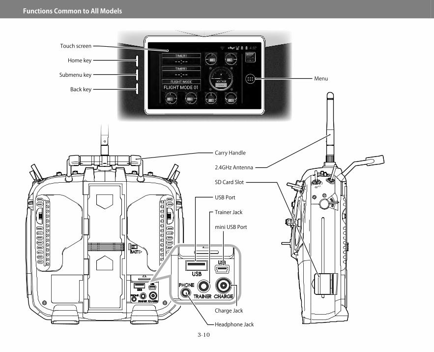
USB Port
mini USB Port
Trainer Jack
Headphone Jack
Charge Jack
Back key
Submenu key
Home key
Touch screen
Carry Handle
2.4GHz Antenna
Menu
SD Card Slot
28X_EN.indd 10 2015/02/27 13:42

3-11
Functions▋Common▋to▋All▋Models
▋Names and functions of the input keys
▋Home Screens
The transmitter features a main home screen (returned to when the home key is pressed) as well as 4 additional home screens which can be used for a variety of purposes. The various home screens are accessed by ‘swiping’ the screen left and right.Widgets can be added to each of these screens – see page8-1 to learn all about widgets. These widgets allow the display of information during flight – such as trim positions, telemetry data, etc.
Pressing this key returns the display to the previous screen. This is very useful when programming various functions.
Back key
• Pressing this key while on the home screen gives access to the wallpaper and system settings menus.
• Pressing this key while within a function gives access to various submenus (if available).
Submenu key
If this key is pressed at any time, the transmitter screen returns to the main home screen.
Home key
This transmitter employs a touch screen. When programming the transmitter, almost all operations can be performed very intuitively using the touch screen. There are also three standard button keys.
Touch screenTouch screen
HOME
LEFT 1 RIGHT 1LEFT 2 RIGHT 2
28X_EN.indd 11 2015/02/27 13:42

3-12
Functions▋Common▋to▋All▋Models
Notification/Status bar
Dock bar
Desktop
・ Status area Status of the model, remaining battery capacity, and
other similar information is displayed.
・ Notification area Status of USB, WiFi, etc. is displayed.
・ Dock Up to 4 icons can be placed here.
・ Menu button Used to switch to the function, system, other
application, or the widgets menu
・ Desktop In this area, items such as shortcuts to the function, system, other
applications and widgets displaying telemetry can be placed.
・ Dock bar The dock bar is a fixed display area. Even if the home screen is changed to another page,
contents on the dock bar will remain the same. Since the dock bar is displayed on all home screen
pages, it is useful to register frequently used items on the bar.
▋▋About▋items▋and▋widgets※ 1 ・・・Icons
An icon refers to a shortcut to an application from the function/system/other lists, and it can be placed on the home screen or dock bar. By touching the icon, you can activate and use the function.
※ 2・・・WidgetsA widget refers to a function that can be placed on the home screen, for example, to display current flight mode or telemetry values, or a small program, such as a calculator or Music Player. � For details about placing these items on the home screen, seeAddingitemstothehomescreen,page3-13.
28X_EN.indd 12 2015/02/27 13:42

3-13
Functions▋Common▋to▋All▋Models
▋Adding items to the home screen1)Display the home screen where you
would like to place an item.If there is no space to place the item, make a space by, for example, removing unnecessary items.
2)Touch the application menu button to display a screen for selecting function/system/other/widgets.Touch and hold an icon you would like to place on the home screen.The shortcut of the icon becomes movable and the screen is changed to the home screen.
3)Move the icon to your favorite position on the home screen.When you release the icon, it will be placed on the selected home screen.If you would like to place the icon on the next home screen (the left page) while the icon is movable, move the icon to the left edge of the screen.The main home screen will be changed to the next page on the left.�� You cannot move to the right page.
4)The icon can also be placed on the dock bar.The icons placed on the dock bar are always displayed even when the home screen is changed. It is thus useful to place functions that are frequently used.
※ Display forms (size or shape) of icons for timer, trim, and other widgets can be selected.Touch the icon to display the sub window and the selection dialog, and select your favorite display forms.
▋Removing items from the home screen1)Touch and hold an icon you would like
to remove so that the icon becomes movable.
2)Confirm that a mark " × " is displayed at the left top of the screen and move the icon onto the mark " × ".When you release the icon, it will be removed.
�� Even if an icon of a function is removed from the home screen, the function itself is not deleted.
▋Grouping itemsFunctions on the list screen can be grouped together (however, icons for telemetry cannot be grouped).1)Attach an icon to the home screen as described on the left side of this
page.2)Touch and move another icon that you would like to group together onto
the icon attached to the home screen.After a blue circle appears, release your finger to group these icons.
3)When you touch the icons placed together, grouped functions are displayed.You can enter a name under the grouped icons.
Menu
28X_EN.indd 13 2015/02/27 13:42
3-14
Functions▋Common▋to▋All▋Models
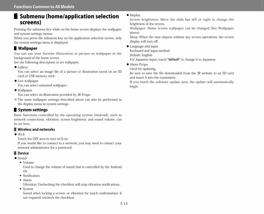
▋Submenu (home/application selection screens)
Pressing the submenu key while on the home screen displays the wallpaper and system settings menus.When you press the submenu key on the application selection screen, only the system settings menu is displayed.
▋▋WallpaperYou can use your favorite illustration or picture as wallpaper in the background of the home screen.See the following description to set wallpaper.
GalleryYou can select an image file of a picture or illustration saved on an SD card or USB memory stick. Live wallpaperYou can select animated wallpaper. WallpaperYou can select an illustration provided by JR Propo.
※ The same wallpaper settings described above can also be performed in the display menu in system settings.
▋▋System▋settingsBasic functions controlled by the operating system (Android), such as network connections, vibration, screen brightness, and sound volume, can be set here.▋▋Wireless▋and▋networks Wi-fiTouch the OFF area to turn wi-fi on.If you would like to connect to a network, you may need to contact your network administrator for a password.▋▋Device Sound
��VolumeUsed to change the volume of sound that is controlled by the Android OS.��Notification��AlarmVibration: Unchecking the checkbox will stop vibration notifications.��SystemSound when locking a screen, or vibration for touch conformation: if not required, uncheck the checkbox.
DisplayScreen brightness: Move the slide bar left or right to change the brightness of the screen.Wallpaper: Home screen wallpaper can be changed (See Wallpaper above).Sleep: When the time elapses without any screen operations, the screen display will turn off. Language and inputKeyboard and input methodDefault: EnglishFor Japanese input, touch “default” to change it to Japanese. About PropoUsed for updating.Be sure to save the file downloaded from the JR website to an SD card and insert it into the transmitter.If you touch the software update area, the update will automatically begin.
28X_EN.indd 14 2015/02/27 13:42
3-15
Functions▋Common▋to▋All▋Models
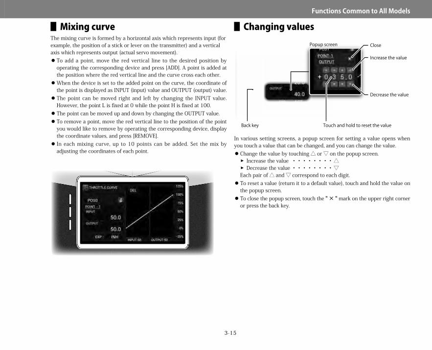
▋Mixing curveThe mixing curve is formed by a horizontal axis which represents input (for example, the position of a stick or lever on the transmitter) and a vertical axis which represents output (actual servo movement).
To add a point, move the red vertical line to the desired position by operating the corresponding device and press [ADD]. A point is added at the position where the red vertical line and the curve cross each other. When the device is set to the added point on the curve, the coordinate of the point is displayed as INPUT (input) value and OUTPUT (output) value. The point can be moved right and left by changing the INPUT value. However, the point L is fixed at 0 while the point H is fixed at 100. The point can be moved up and down by changing the OUTPUT value. To remove a point, move the red vertical line to the position of the point you would like to remove by operating the corresponding device, display the coordinate values, and press [REMOVE]. In each mixing curve, up to 10 points can be added. Set the mix by adjusting the coordinates of each point.
▋Changing values
In various setting screens, a popup screen for setting a value opens when you touch a value that can be changed, and you can change the value.
Change the value by touching △ or ▽ on the popup screen.�� Increase the value ・・・・・・・・△��Decrease the value ・・・・・・・・▽
Each pair of △ and ▽ correspond to each digit. To reset a value (return it to a default value), touch and hold the value on the popup screen. To close the popup screen, touch the " × " mark on the upper right corner or press the back key.
Increase the value
ClosePopup screen
Decrease the value
Touch and hold to reset the valueBack key
28X_EN.indd 15 2015/02/27 13:42
3-16
Functions▋Common▋to▋All▋Models
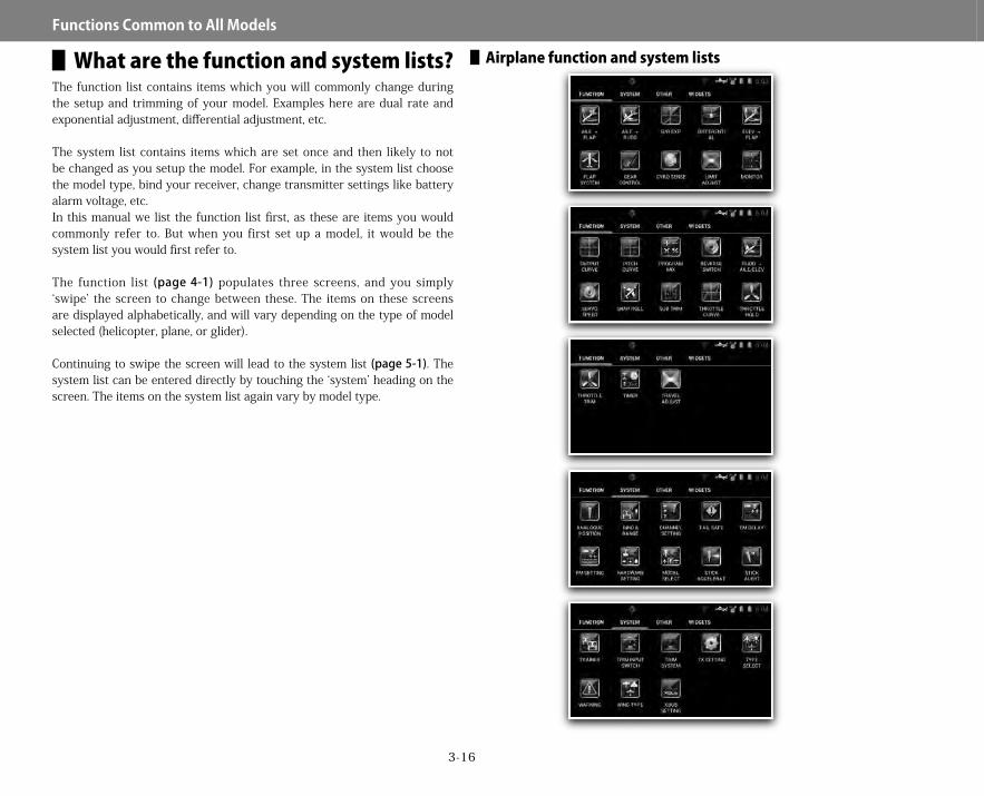
▋What are the function and system lists?The function list contains items which you will commonly change during the setup and trimming of your model. Examples here are dual rate and exponential adjustment, differential adjustment, etc.
The system list contains items which are set once and then likely to not be changed as you setup the model. For example, in the system list choose the model type, bind your receiver, change transmitter settings like battery alarm voltage, etc.In this manual we list the function list first, as these are items you would commonly refer to. But when you first set up a model, it would be the system list you would first refer to.
The function list (page4-1) populates three screens, and you simply ‘swipe’ the screen to change between these. The items on these screens are displayed alphabetically, and will vary depending on the type of model selected (helicopter, plane, or glider).
Continuing to swipe the screen will lead to the system list (page5-1). The system list can be entered directly by touching the ‘system’ heading on the screen. The items on the system list again vary by model type.
▋▋Airplane▋function▋and▋system▋lists
28X_EN.indd 16 2015/02/27 13:42
3-17
Functions▋Common▋to▋All▋Models
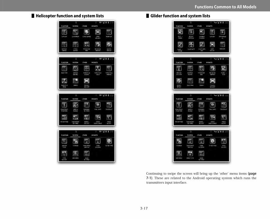
▋▋Helicopter▋function▋and▋system▋lists ▋▋Glider▋function▋and▋system▋lists
Continuing to swipe the screen will bring up the ‘other’ menu items (page7-1). These are related to the Android operating system which runs the transmitters input interface.
28X_EN.indd 17 2015/02/27 13:42

3-18
Functions▋Common▋to▋All▋Models
▋▋Other
▋▋Widgets
Finally you can access the widgets menu (page8-1).
Four additional widgets can be placed on this quick access menu to allow easy access to important functions at all times. See page8-1to learn all about widgets.
▋New model setupWhen you create a new model, it is important some basic parameters are defined when you start setting up the model.
▋▋Airplane①Create a new model in the model select menu (page
5-1). Select ‘airplane’ as the aircraft type. Name the model with a name you can recognize.
②Select XBus if required (page5-22). XBus is used with the JR Axis gyro system, and when using other XBus products.
③Plug the bind plug into your receiver, plug in a battery, and bind the transmitter to the receiver (page5-13).
④Next select the required wing, tail and throttle types (page5-17).⑤Next define any additional flight modes (page5-3). Normally the three
default modes is enough, but you may wish to redefine the names or switches used to select these modes.
⑥Next go to channel settings (page5-15). Here you can move the position of the servo outputs on the receiver. Here you can also define channels as gyro outputs, which must be done before you can use the gyro menu. You can set the gyro values in the gyro menu (page4-15).
⑦Now you may wish to setup the throttle stick to start and stop a timer. You need to define the throttle stick as an ‘analogue position switch – APS’ (page5-7). You will set the input as the throttle channel, and define the left end as ‘off’ and the other two positions as ‘on’.
⑧Having done this, go ahead and set up a timer (page4-53) using the APS to turn it on and off.
⑨Now you should plug in your servos, and get them working in the correct directions. Use the servo reverse function (page4-7) to do this.
⑩Next set the servo arms in neutral. The sub trim function (page4-6) is useful here.
⑪Now set maximum servo travel using the travel adjust menu (page4-4).⑫Next setup dual rates and exponential (page4-1). This function is
useful to allow different control responses to be selected in flight. It is common to use the flight mode switch to control all your dual rates at the same time.
⑬Next setup aileron differential if required (page4-26). Differential is available if using more than one aileron servo. Most models require slightly more up than down aileron throw to roll in an axial manner.
This completes the basic setup of an airplane. You may wish to use some of the advanced functionality of the transmitter – set up a throttle curve
Airplane
28X_EN.indd 18 2015/02/27 13:42
3-19
Functions▋Common▋to▋All▋Models
for linear motor response (page4-9), change the behavior of the throttle trim (page4-21), set up the snap roll function (page4-25) and continue to explore the radio further.
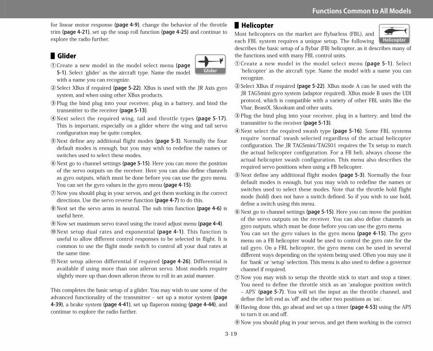
▋▋Glider①Create a new model in the model select menu (page
5-1). Select ‘glider’ as the aircraft type. Name the model with a name you can recognize.
②Select XBus if required (page5-22). XBus is used with the JR Axis gyro system, and when using other XBus products.
③Plug the bind plug into your receiver, plug in a battery, and bind the transmitter to the receiver (page5-13).
④Next select the required wing, tail and throttle types (page5-17). This is important, especially on a glider where the wing and tail servo configuration may be quite complex.
⑤Next define any additional flight modes (page5-3). Normally the four default modes is enough, but you may wish to redefine the names or switches used to select these modes.
⑥Next go to channel settings (page5-15). Here you can move the position of the servo outputs on the receiver. Here you can also define channels as gyro outputs, which must be done before you can use the gyro menu. You can set the gyro values in the gyro menu (page4-15).
⑦Now you should plug in your servos, and get them working in the correct directions. Use the servo reverse function (page4-7) to do this.
⑧Next set the servo arms in neutral. The sub trim function (page4-6) is useful here.
⑨Now set maximum servo travel using the travel adjust menu (page4-4).⑩Next setup dual rates and exponential (page4-1). This function is
useful to allow different control responses to be selected in flight. It is common to use the flight mode switch to control all your dual rates at the same time.
⑪Next setup aileron differential if required (page4-26). Differential is available if using more than one aileron servo. Most models require slightly more up than down aileron throw to roll in an axial manner.
This completes the basic setup of a glider. You may wish to use some of the advanced functionality of the transmitter – set up a motor system (page4-39), a brake system (page4-41), set up flaperon mixing (page4-44), and continue to explore the radio further.
▋▋HelicopterMost helicopters on the market are flybarless (FBL), and each FBL system requires a unique setup. The following describes the basic setup of a flybar (FB) helicopter, as it describes many of the functions used with many FBL control units.①Create a new model in the model select menu (page5-1). Select
‘helicopter’ as the aircraft type. Name the model with a name you can recognize.
②Select XBus if required (page5-22). XBus mode A can be used with the JR TAGSmini gyro system (adaptor required). XBus mode B uses the UDI protocol, which is compatible with a variety of other FBL units like the Vbar, BeastX, Skookum and other units.
③Plug the bind plug into your receiver, plug in a battery, and bind the transmitter to the receiver (page5-13).
④Next select the required swash type (page5-16). Some FBL systems require ‘normal’ swash selected regardless of the actual helicopter configuration. The JR TAGSmini/TAGS01 requires the Tx setup to match the actual helicopter configuration. For a FB heli, always choose the actual helicopter swash configuration. This menu also describes the required servo positions when using a FB helicopter.
⑤Next define any additional flight modes (page5-3). Normally the four default modes is enough, but you may wish to redefine the names or switches used to select these modes. Note that the throttle hold flight mode (hold) does not have a switch defined. So if you wish to use hold, define a switch using this menu.
⑥Next go to channel settings (page5-15). Here you can move the position of the servo outputs on the receiver. You can also define channels as gyro outputs, which must be done before you can use the gyro menu.You can set the gyro values in the gyro menu (page4-15). The gyro menu on a FB helicopter would be used to control the gyro rate for the tail gyro. On a FBL helicopter, the gyro menu can be used in several different ways depending on the system being used. Often you may use it for ‘bank’ or ‘setup’ selection. This menu is also used to define a governor channel if required.
⑦Now you may wish to setup the throttle stick to start and stop a timer. You need to define the throttle stick as an ‘analogue position switch – APS’ (page5-7). You will set the input as the throttle channel, and define the left end as ‘off’ and the other two positions as ‘on’.
⑧Having done this, go ahead and set up a timer (page4-53) using the APS to turn it on and off.
⑨Now you should plug in your servos, and get them working in the correct
Glider
Helicopter
28X_EN.indd 19 2015/02/27 13:42

3-20
Functions▋Common▋to▋All▋Models
directions. Use the servo reverse function (page4-7) to do this. With most FBL units, you would set the transmitter reverse directions to match the FBL unit.
⑩Next set the servo arms in neutral. The sub trim function (page4-6) is useful here. With most FBL units, you would set the transmitter sub trim to match the FBL unit.
⑪Now set maximum servo travel using the travel adjust menu (page4-4). With most FBL units, you would set the transmitter travel adjust to match the FBL unit.
⑫Next setup dual rates and exponential (page4-1). This function is useful to allow different control responses to be selected in flight. It is common to use the flight mode switch to control all your dual rates at the same time.
⑬Next setup the required pitch curves (page4-11). These should be set to match your required flight style.
⑭Now setup the required throttle curves (page4-9). These should be set to match your required flight style.
⑮Again, depending on your setup, the governor menu (page4-18) may be used to control rotor rpm.
This completes the basic setup of an airplane. You may wish to use some of the advanced functionality of the transmitter – set up a throttle curve for linear motor response (page4-9), change the behavior of the throttle trim (page4-21), set up the snap roll function (page4-25) and continue to explore the radio further.
▋Flight modes▋▋Function▋explanation
The flight mode function allows switching between various aircraft settings using a single switch.
Up to fifteen flight modes are possible. The default settings vary with model type. The flight mode that is currently selected can be confirmed on the home screen using the flight mode widget.
Flight mode display names can be changed in flight mode setup, in the system list (page5-3).
▋▋Functions▋that▋can▋be▋selected▋by▋flight▋modeAlmost every function in this transmitter can have multiple options selected by flight mode switch position. Trims, dual rate settings, mixes, etc can all be changed with the flip of one switch. Simply select flight mode as the switch for various functions. This is further explained in the switch selection information on page3-22.
▋▋Functions▋relevant▋for▋different▋model▋types
The functions available in your radio function and system menus vary depending on the selected model type – either airplane, helicopter or glider. In this manual we use the above symbols to indicate for which model types each function is available.
▋▋Display▋of▋the▋current▋flight▋modeThe flight mode that is currently used is displayed as a widget on the home screen at the time of shipment (seeAboutitemsandwidgets,page3-12).Since a widget is an item that can be deleted from or placed again on the home screen, the display of the flight mode (the flight mode widget) may not be present.When the flight mode widget is placed on the home screen, the current flight mode can be confirmed. Touching the flight mode widget allows the voice annunciation options to be changed (page 7-4).The default settings for flight mode switches for helicopter and glider at the time of shipment are different from those for airplanes.If any changes are necessary, change switch allocated to each flight mode in flight mode setup (page5-3).
Airplane Helicopter Glider
28X_EN.indd 20 2015/02/27 13:42

3-21
Functions▋Common▋to▋All▋Models
▋▋Helicopter Normal mode(NORMAL) ・・・・・・・・K SW POS0 Stunt mode 1(STUNT-1) ・・・・・・・・・K SW POS1 Stunt mode 2(STUNT-2) ・・・・・・・・・K SW POS2 ▽ Hold mode(HOLD) ▽ Stunt mode 3(STUNT-3) ▽ Stunt mode 4(STUNT-4)
" ▽ " indicates a mode that can be added in flight mode setup.▋▋Expanding▋flight▋modes
Add flight modes, such as stunt mode 3 or 4, as necessary.To add flight modes, touch the add area in flight mode setup in the system list to add modes, and set names, types (only for helicopters), and switches (seeFLIGHTMODESETUP,page5-3).※ Hold mode is not allocated by default. Set by changing the type to hold.※ When conditions are met for several flight modes at the same time, the
hold type is prioritized over other flight modes. Priorities for other flight modes can be defined in priority settings.
▋▋Airplane Flight mode 01(FLIGHT MODE 01) ・・・・F SW POS0 Flight mode 02(FLIGHT MODE 02) ・・・・F SW POS1 Flight mode 03(FLIGHT MODE 03) ・・・・F SW POS2 ▽ Flight mode 04(FLIGHT MODE 04) ▽ Flight mode 05(FLIGHT MODE 05) ▽ Flight mode 06(FLIGHT MODE 06)
▋▋Using▋flight▋modes" ▽ " indicates a mode that can be added in flight mode setup.* Priorities for flight modes when conditions are met for several flight modes can be defined in priority settings included in the submenu (seeFLIGHTMODESETUP,page5-3).
▋▋Glider ▲ Launch mode(LAUNCH) ・・・・・・・C SW POS1 ▲ Speed mode(SPEED) ・・・・・・・・・K SW POS0 ▲ Thermal mode(THERMAL) ・・・・・・K SW POS1 ▲ Cruise mode(CRUISE) ・・・・・・・・・K SW POS2 ▽ Landing mode(LANDING) ▽ Distance mode(DISTANCE)
" ▲ " indicates a mode that is included in the default settings." ▽ " indicates a mode that is added in the flight mode setup.When further expansion of flight modes is necessary, you can add flight modes such as landing.To add flight modes, touch the add area in flight mode setup in the system list to add modes, and set names and switches.* Priorities for flight modes when conditions are met for several flight modes can be defined in priority settings included in the submenu (seeFLIGHTMODESETUP,page5-3).▋▋Examples▋of▋items▋that▋can▋be▋changed▋by▋flight▋mode
Items that can be changed by flight mode include digital trims and various functions.When you are in various switch selection dialogues, you can often select flight mode as a switch selection.
Current flight mode
28X_EN.indd 21 2015/02/27 13:42
3-22
Functions▋Common▋to▋All▋Models
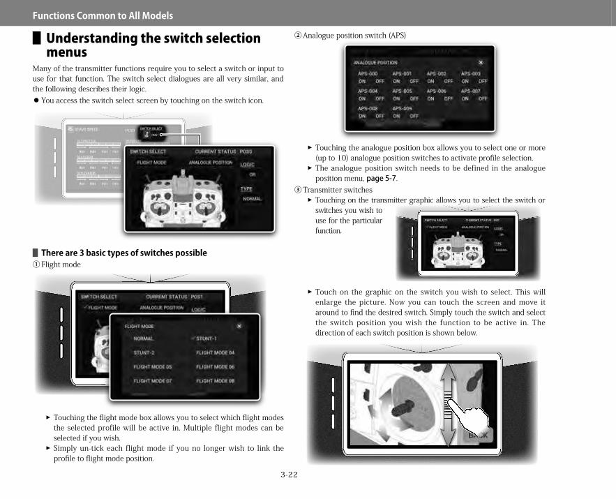
▋Understanding the switch selection menus
Many of the transmitter functions require you to select a switch or input to use for that function. The switch select dialogues are all very similar, and the following describes their logic.
You access the switch select screen by touching on the switch icon.
▋▋There▋are▋3▋basic▋types▋of▋switches▋possible①Flight mode
��Touching the flight mode box allows you to select which flight modes the selected profile will be active in. Multiple flight modes can be selected if you wish.��Simply un-tick each flight mode if you no longer wish to link the profile to flight mode position.
②Analogue position switch (APS)
��Touching the analogue position box allows you to select one or more (up to 10) analogue position switches to activate profile selection.��The analogue position switch needs to be defined in the analogue position menu, page5-7.
③Transmitter switches��Touching on the transmitter graphic allows you to select the switch or switches you wish to use for the particular function.
��Touch on the graphic on the switch you wish to select. This will enlarge the picture. Now you can touch the screen and move it around to find the desired switch. Simply touch the switch and select the switch position you wish the function to be active in. The direction of each switch position is shown below.
28X_EN.indd 22 2015/02/27 13:42

3-23
Functions▋Common▋to▋All▋Models
��Note that the transmitter sticks can be used directly as 3 position switches, or alternatively they can be used as an analogue position switch (page5-7) with greater flexibility.��Multiple switches or stick switches (and positions) can be selected.
▋▋Switch▋logic��First select the type of switching - normal or trigger – both of which have different logics associated with them.
▋Normal–Possiblelogicsare:
On The profile is on regardless of switch position Off The profile is off regardless of switch position Or The profile is active if any one of the switches (flight mode, APS or
transmitter switches) is on. And The profile is active only when all the selected switches are on.▋Trigger–Bothonandofftriggerscanbesetseparately.Possiblelogicsfortheonandofftriggersare: On The profile is on regardless of switch position Off The profile is off regardless of switch position Or The profile is active if any one of the switches (flight mode, APS or
transmitter switches) is on. And The profile is active only when all the selected switches are on.
0
0
0
1
1
1
2
2
0
1
2
0
0
0
1
1
1
2
2
0
1
2
28X_EN.indd 23 2015/02/27 13:42

4-1
Function▋List
DUAL RATE & EXPONENTIAL▋▋Function▋explanation
This function allows different control throw, exponential and user defined curve settings for aileron, elevator, rudder, and one auxiliary channel, selectable using switches on the transmitter. Exponential is a curve adjusting function that logarithmically changes the servo movement in response to the stick action, allowing the movement in the vicinity of the neutral position to be adjusted from mild (+ direction) to quick (- direction) without changing the maximum control surface angle. Additionally, a user
definable curve function allows up to 8 user definable points to be used to create your own curves, rather than use an exponential setting. Adjustments made can be confirmed by looking at the graph on the screen. A sub menu provides access to a delay function and auxiliary channel selection.
▋▋Setting▋method①From the home screen, press the menu
button on the touch screen.②From the function list, select D/R EXP (dual
rate and exponential).③Next select the channel you wish to set up
dual rate and exponential for. Touch the channel select zone, and select from the options given. If you wish to setup dual rates and exponential for an auxiliary channel, you must first select the auxiliary channel in the submenu. Return to the previous screen by pressing the back button.
④Now touch the ‘position’ indication. From here you can ‘add ’ poss ib le D/R and exponential curves, so you can use up to 15 different D/R and exponential settings. You can also delete any unwanted curves.
ADD/DEL Positions
Type select options
Dual rate amount
Exponential amountExponential amount
Channel select options Switch select options
Glider
Helicopter
Airplane
28X_EN.indd 1 2015/02/27 13:42

4-2
Function▋List
Return to the previous screen by pressing the back button.⑤Next click the switch icon. Here you are able to select from up to
15 switches or combinations of switches to select different D/R and exponential curves which you can define. Refer topage3-22(Understandingtheswitchselectionmenus) for a description on how to select various switches.
⑥Now click on the position icon associated with the switch you just selected. Here you can decide which curve will be active when the switch position criteria are met.
⑦Continue setting up to 15 D/R and exponential selections. Use the back button to return to the main D/R and exponential screen.
⑧Select each previously programmed switch position in turn (or touch the ‘POSx’ indicator and select from the options), and click on the normal or curve icon to select a standard exponential curve, or a user defined curve setting.
⑨Now touch the D/R icon to set the left/right (up/down) total throw for each direction, and also set the exponential settings.
⑩With the control stick in the middle position, settings can changed for both control directions at the same time. Touching the input area for a couple of seconds returns the values to the default settings.
⑪Alternatively, if curve was selected, you can add up to 8 user defined points to the response curve as well as change the end points of the curve. Points can be deleted or added as required.
⑫The position of these user de f ined po in t s can be changed by positioning the control stick over a defined point and touching ‘Input’, and changing the value here.
⑬The value of these user defined points can be changed by positioning the control stick over a defined point and touching ‘Output’, and changing the value here.
⑭You can also click on "EXP" to activate or inhibit this to smooth the response curve.
▋▋Submenu▋functionsPressing the submenu button provides access to the trim input function, a delay function as well as auxiliary channel selection.
Trim inputThis option allows a trim input device (seepage5-8) to be chosen to fine tune selected points on the dual rate curve. The trim input device must first be defined before it can be activated. By using the trim input, it is be possible to change the dual rate value using a trim lever, making it is easy to fine tune during flight.This option is only available when 'curve' is selected. DelayTouching the delay indication opens they delay menu. Here you can program delays between various dual rate settings, so settings change smoothly. Use the ‘add’ button to add up to ten different delays as required. You can select which dual rate profile change the delay applies to, and set the delay time between 0-10 seconds. Servos operate slowly when transitioning between selected dual rate settings. Auxiliary channel selectionFrom this menu it is possible to select one auxiliary channel to also apply dual rate and exponential settings for. Simply select the required auxiliary channel from the list of available channels.
Points ADD/DEL
Sub menu key
28X_EN.indd 2 2015/02/27 13:42

4-3
Function▋List
Finally, you can touch the channel selection to select the next channel to program D/R and exponential settings for. Once you are finished, press the back button twice to return to the home screen.
When you are in the switch selection dialogue, it is possible to change the priority of dual rate selection. When two or more dual rate settings are active (on), the highest up the list (closest to #1) is selected as active automatically. To move a particular dual rate selection higher up the priority list, simply touch on the number, and then 'yes' to move. This moves the particular dual rate one position up the list. continue in this manner to move it higher up the list as required. The dual rate setting numerical value can be between 0 and 150%, and expo can be between 0 and ± 100. To reset a numerical value to default, simply long touch on the value. By moving the appropriate control stick, the numerical values can be independently changed for left and right (up and down), so that the control surface angles and curves can be individually adjusted. Typically you may decide to use a flight mode switch to control D/R and exponential setting for ailerons, elevator and rudder simultaneously. The D/R function is useful for allowing high control throws for maneuvers such as snaps and spins, and lower control throws for general flying
▋▋Caution▋note Operate the servos and switches and carefully confirm the operational settings before flying.
Tips
28X_EN.indd 3 2015/02/27 13:42
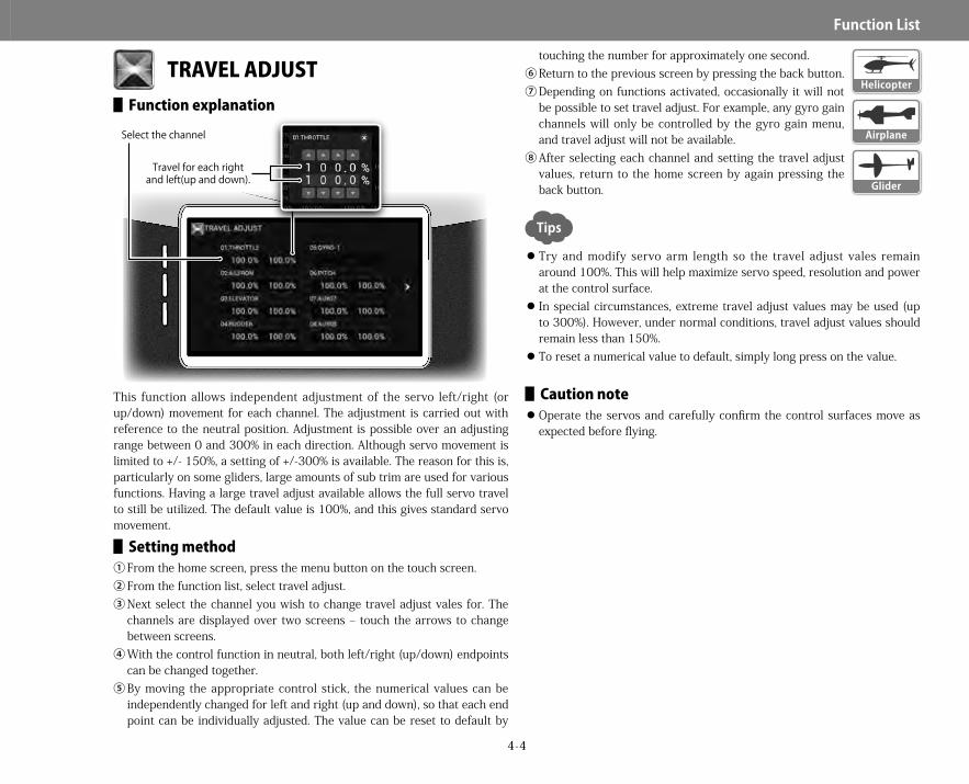
4-4
Function▋List
TRAVEL ADJUST▋▋Function▋explanation
This function allows independent adjustment of the servo left/right (or up/down) movement for each channel. The adjustment is carried out with reference to the neutral position. Adjustment is possible over an adjusting range between 0 and 300% in each direction. Although servo movement is limited to +/- 150%, a setting of +/-300% is available. The reason for this is, particularly on some gliders, large amounts of sub trim are used for various functions. Having a large travel adjust available allows the full servo travel to still be utilized. The default value is 100%, and this gives standard servo movement.
▋▋Setting▋method①From the home screen, press the menu button on the touch screen.②From the function list, select travel adjust.③Next select the channel you wish to change travel adjust vales for. The
channels are displayed over two screens – touch the arrows to change between screens.
④With the control function in neutral, both left/right (up/down) endpoints can be changed together.
⑤By moving the appropriate control stick, the numerical values can be independently changed for left and right (up and down), so that each end point can be individually adjusted. The value can be reset to default by
touching the number for approximately one second.⑥Return to the previous screen by pressing the back button.⑦Depending on functions activated, occasionally it will not
be possible to set travel adjust. For example, any gyro gain channels will only be controlled by the gyro gain menu, and travel adjust will not be available.
⑧After selecting each channel and setting the travel adjust values, return to the home screen by again pressing the back button.
Try and modify servo arm length so the travel adjust vales remain around 100%. This will help maximize servo speed, resolution and power at the control surface. In special circumstances, extreme travel adjust values may be used (up to 300%). However, under normal conditions, travel adjust values should remain less than 150%. To reset a numerical value to default, simply long press on the value.
▋▋Caution▋note Operate the servos and carefully confirm the control surfaces move as expected before flying.
Select the channel
Travel for each right and left(up and down).
Helicopter
Airplane
Glider
Tips
28X_EN.indd 4 2015/02/27 13:42

4-5
Function▋List
LIMIT ADJUST
▋▋Function▋explanationWhen multiple channel mixing is used, the resultant servo movement angle may become too large and the linkage or control surface may jam, causing the servo to stall, and an unreasonable force be applied to the linkages. If limit values are set, it is possible to limit the maximum movement of the servos, regardless of programmable mixing, etc. The limit can be set independently for each direction, over a range of 0-150%.
▋▋Setting▋method①From the home screen, press the menu button on the touch screen.②From the function list, select limit adjust.③Next select the channel you wish to change limit adjust vales for. Do this
by touching the appropriate limit values. The function spans two pages – use the arrows to change between pages.
④With the control function in neutral, both left/right (up/down) endpoints can be changed together.
⑤By moving the appropriate control stick, the numerical values can be independently changed for left and right (up and down), so that each end point can be individually adjusted. Touching a particular limit for more than one second will return the limit to its default value. Return to the previous screen by pressing the back button.
⑥Depending on functions activated, occasionally it will not be possible to
set channel limits. For example, any gyro gain channels will only be controlled by the gyro gain menu, and limit adjust will not be available.
⑦After selecting each channel and setting the limit adjust values, return to the home screen by again pressing the back button.
This function is very handy when programmable mixers may overdrive a servo to the point the servo stalls. Use the limit adjust to provide an appropriate hard endpoint for servo movement. To reset a numerical value to default, simply long press on the value.The default values for limit adjust are +/- 150%
▋▋Caution▋note Operate the servos and carefully confirm the control surfaces move as expected before flying.
Select the channel
Limit for each right and left(up and down).
Glider
Airplane
Helicopter
Tips
28X_EN.indd 5 2015/02/27 13:42

4-6
Function▋List
SUB TRIM
▋▋Function▋explanationThis allows fine trimming of the servos attached to each channel. The sub trim should be used as a fine adjustment when the servo horn angle is not 90 degrees with regard to the linkage. Note that if large amounts of sub trim are used, it will affect the maximum deflection of the servo. It is therefore recommended to use only small values here. The sub trim can be adjusted over a range of +/-512. We would recommend limiting sub trim values to +/-100. Higher values should only be used in specific situations.
▋▋Setting▋method①From the home screen, press the menu button on the touch screen.②From the function list, select sub trim.③Next select the channel you wish to change sub trim values for. With the
control function in neutral, alter the sub trim as required. Return to the previous screen by pressing the back button.
④Depending on functions activated, occasionally it will not be possible to change sub trim values. For example, any gyro gain channels will only be controlled by the gyro gain menu, and sub trim will not be available.
⑤After selecting each channel and setting the sub trim values, return to the home screen by again pressing the back button.
Be sure to only use minimal amounts of sub trim. First position the servo arm close to the correct position, and then use sub trim to fine tune as required. When trimming your model, it is always best to alter the linkage lengths as necessary, rather than use sub trim. Extreme sub trim values are available – please use these with caution. In some specific installations these can be very useful. To reset a numerical value to default, simply long press on the value.
▋▋Caution▋note Operate the servos and carefully confirm the control surfaces move as expected before flying.
Sub trim amount
Select the channel
Glider
Airplane
HelicopterTips
28X_EN.indd 6 2015/02/27 13:42

4-7
Function▋List
REVERSE SWITCH
▋▋Function▋explanationThis function reverses the servo operating direction of each channel.
▋▋Setting▋method①From the home screen, press the menu button on the touch screen.②From the function list, select reverse switch.③Under each channel is an indication of current channel direction – either
‘normal’ or ‘reverse’. Touch this indication to change the servo direction for the required channel. You will then need to confirm this change by touching on ‘yes’.
④Depending on functions activated, occasionally it will not be possible to set channel reverse. For example, any gyro gain channels will only be controlled by the gyro gain menu, and reverse will not be available.
⑤After setting the servo directions, return to the home screen by pressing the back button.
※ The channel names on the screen will differ according to the model type.
▋▋Caution▋note�� ImportantWhenever you make changes to the model setup (and reverse switches in particular), please reset the failsafe settings (seepage5-14). For example, if the throttle failsafe had been set to motor cut, and now the throttle servo is reversed, the failsafe setting will now be for full throttle – a very dangerous situation. After completing all transmitter settings, or after changing any transmitter settings, always be sure to set the failsafe again and check correct operation.
Confirmation popupCurrent channel directionGlider
Airplane
Helicopter
28X_EN.indd 7 2015/02/27 13:42

4-8
Function▋List
SERVO SPEED
▋▋Function▋explanationThis function slows down the operation speed of the servos independently for each channel. This function should be considered as a speed limiter. The speed setting can be set separately for left/right (up/down), and different speeds can be set for servo travel away from neutral, and then returning to neutral. Additionally, two different speed profiles can be set and controlled using optional switches, including a programmed throttle position switch.
▋▋Setting▋method①From the home screen, press the menu button on the touch screen.②From the function list, select servo speed.
There are 3 pages of servo speed selections – use the left and right arrows to change between the screens.
③Depending on functions activated, occasionally it will not be possible to change servo speed. For example, any gyro gain channels will only be
controlled by the gyro gain menu, and servo speed will not be available.
④Two different servo speed profiles can be selected. First select a switch for choosing between these two profiles. Touch the switch icon and select a switch or switches in the usual manner. seepage3-22 for information on switch selection. Use the back button to return to the previous screen.
⑤Next select the profile you wish to modify. Either select the profile using the switch you have selected, or touch the ‘POSx’ indicator, and select form the available options.
⑥Under each channel is an indication of current servo speed. ‘inh’ means the servo is being moved at its fastest speed. A slower speed of 0.1-10 seconds over half the servo travel can be set. This indicates the time that the servo takes to rotate through 60 degrees. Note there may be some slight variation depending on the servos used. The servo can be slowed independently when moving to the left or right (up or down) and also have an independent speed set when returning to neutral from either direction.
⑦After setting the servo speeds, return to the home screen by pressing the back button.
※ The channel names on the screen will differ according to the model type. This function cannot move a servo faster than its rated maximum speed. ‘inh’ (inhibit) means the servo is being moved as fast as it can. The slowest programmable transit speed for half the servo travel is 10 seconds.
Depending on the application, some channels may not be able to have a speed set, and ‘----‘ will be displayed. This function is useful for slowing down retracts and flaps. It would not normally be recommended to slow down any primary control function.
▋▋Caution▋noteWhen the servo speed has been set, carefully confirm the servo speeds using actual switch operation before flying.
Glider
Airplane
Helicopter
Tips
28X_EN.indd 8 2015/02/27 13:42

4-9
Function▋List
THROTTLE CURVE
▋▋Function▋explanationThis function adjusts throttle servo operation in response to throttle stick operation. The servo position can be set independently for a maximum of 8 point positions. In addition, an EXP (exponential) function can be activated to smooth the curve between the programmed points. Several different throttle curves can be programmed, and selected from a wide variety of switches. This function can set a maximum of 15 different throttle curves, both for airplanes and helicopters. Additional options are available from the submenu, depending on the model type, including delay to smooth the transit between curves, trim input settings, hover throttle setting, throttle trim offset and curve type selection.
▋▋Setting▋method①From the home screen, press the menu button on the touch screen.②From the function list, select throttle curve.③Up to 15 different curves can be programmed. First touch on ‘POSx’
and add curves as required by touching ‘position add’. Curves can be removed by touching ‘position delete’. Use the back button to return to the previous screen.
④Now touch the switch icon to define switches to activate the required
throttle curves. Select a switch or switches in the usual manner (seepage3-22).
⑤Next select the curve you wish to modify. Either select the profile using the switch you have selected, or touch the ‘POSx’ indicator, and select form the available options.
⑥There are three initial curve points set at the low, center, and high positions. To add a point, set the throttle stick to the desired position and press "ADD" on the screen. To delete a point, position the throttle stick so the point is highlighted, and press "DEL" on the screen.
⑦To change vales at each point, position the throttle stick at the desired point, and click on ‘output’ to change the value at that point.
⑧The position of the points can be fine-tuned by pressing ‘input’, and then changing the horizontal position of the point.
⑨The ‘EXP’ function can be activated to smooth the throttle curve between points. Simply touch on ‘INH’ and change to ‘ACT’.
⑩Pressing the sub menu button allows the setting of several other options depending on the model type. Further information is given below.
⑪After setting the required throttle curves, return to the home screen by pressing the back button.
Current Flight Mode position
Current point Points ADD/DEL
Numerical Display of the Stick input Position and output position
T h i s c h a n g e s t h e point connections to a Curve.
Each adjusting point input position and output position
Switch select options
Airplane
Helicopter
28X_EN.indd 9 2015/02/27 13:42

4-10
Function▋List
▋HelicopterTypical helicopter throttle curves may look like this:
▋Airplane
The numerical value ‘input’ shows the position of the throttle stick and the numerical value ‘output’ shows the output value to the servo. Adjustment is possible over an adjusting range between -25 and 125% for each of the low to high (up and down) directions.
▋▋Submenu▋functions
Additional submenu features include Delay settingA delay of 0-10 seconds can be used to smooth transition between various curves. Simply touch the delay option and enter a value up to 10 seconds as required. Trim input settingThis option allows a trim input device (seepage5-8) to be chosen to change any selected combination of points on the curve. The trim input device must first be defined before it can be activated. Hovering throttle settingIt is possible to choose which curve points will be changed using the hover throttle trimmer. Throttle trim offsetThis allows different trim positions on each curve. Curve type settingsThis function is useful if you are using a governor which requires a flat line throttle curve. When the setting is changed to ‘gov’, the throttle curve is automatically changed to a flat line, which you can move up and down.▋▋Caution▋note
Actually operate the servos and carefully confirm the settings before flying.
Normal mode (for hovering)
Stunt mode (for 3D)
Tips
Submenu key
28X_EN.indd 10 2015/02/27 13:42
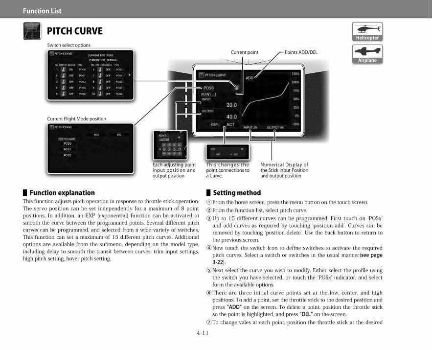
4-11
Function▋List
PITCH CURVE
▋▋Function▋explanationThis function adjusts pitch operation in response to throttle stick operation. The servo position can be set independently for a maximum of 8 point positions. In addition, an EXP (exponential) function can be activated to smooth the curve between the programmed points. Several different pitch curves can be programmed, and selected from a wide variety of switches. This function can set a maximum of 15 different pitch curves. Additional options are available from the submenu, depending on the model type, including delay to smooth the transit between curves, trim input settings, high pitch setting, hover pitch setting.
▋▋Setting▋method①From the home screen, press the menu button on the touch screen.②From the function list, select pitch curve.③Up to 15 different curves can be programmed. First touch on ‘POSx’
and add curves as required by touching ‘position add’. Curves can be removed by touching ‘position delete’. Use the back button to return to the previous screen.
④Now touch the switch icon to define switches to activate the required pitch curves. Select a switch or switches in the usual manner(seepage3-22).
⑤Next select the curve you wish to modify. Either select the profile using the switch you have selected, or touch the ‘POSx’ indicator, and select form the available options.
⑥There are three initial curve points set at the low, center, and high positions. To add a point, set the throttle stick to the desired position and press "ADD" on the screen. To delete a point, position the throttle stick so the point is highlighted, and press "DEL" on the screen.
⑦To change vales at each point, position the throttle stick at the desired
Airplane
Helicopter
Current Flight Mode position
Current point Points ADD/DEL
Numerical Display of the Stick input Position and output position
T h i s c h a n g e s t h e point connections to a Curve.
Each adjusting point input position and output position
Switch select options
28X_EN.indd 11 2015/02/27 13:42

4-12
Function▋List
point, and click on ‘output’ to change the value at that point. ⑧The position of the points can be fine-tuned by pressing ‘input’, and then
changing the horizontal position of the point.⑨The ‘EXP’ function can be activated to smooth the pitch curve between
points. Simply touch on ‘INH’ and change to ‘ACT’.⑩Pressing the sub menu button allows the setting of several other options
depending on the model type. Further information is given below.⑪After setting the required pitch curves, return to the home screen by
pressing the back button.
▋▋Submenu▋functions▋Helicopter
Additional submenu features include Delay settingA delay of 0-10 seconds can be used to smooth transition between various curves. Simply touch the delay option and enter a value up to 10
seconds as required. Trim input settingThis option allows a trim input device (seepage5-8) to be chosen to change any selected combination of points on the curve. The trim input device must first be defined before it can be activated. High pitch settingIt is possible to choose a high pitch trim input device, define its sensitivity, and select a switch to turn the high pitch trim off and on. Hover pitch settingIt is possible to define the curve points the hover pitch trim controls.
▋AirplaneSubmenu features include
Delay settingA delay of 0-10 seconds can be used to smooth transition between various curves. Simply touch the delay option and enter a value up to 10 seconds as required. Trim input settingThis option allows a trim input device (seepage5-8) to be chosen to change any selected combination of points on the curve. The trim input device must first be defined before it can be activated.
The numerical value ‘input’ shows the position of the throttle stick and the numerical value ‘output’ shows the output value to the servo. Adjustment is possible over an adjusting range between -25 and 125% for each of the low to high (up and down) directions. In airplane mode, a pitch servo must first be defined in channel setting (page5-15) for the pitch curve function to be active.
▋▋Caution▋noteAfter the setting, operate the servos and carefully confirm each of the Flight Mode settings before flying.
Submenu key
Tips
28X_EN.indd 12 2015/02/27 13:42

4-13
Function▋List
THROTTLE HOLD
▋▋Function▋explanationThis function is for autorotation landings with helicopters, and can be used as a safety switch while airplanes are on the ground – it places and holds the throttle servo at a low position. Using a selected switch, the engine can be cut, or fixed at an optional slow position. Further, there is also a stick auto function that allows switching of the servo to the hold position when the stick is lowered to a preset position.
▋▋Setting▋method①From the home screen, press the menu button on the touch screen.②From the function list, select throttle hold.③After setting the function, return to the home screen by pressing the
back button.
▋▋Helicopter①Before being able to use throttle hold, it is necessary to
add a switch to the ‘hold’ flight mode. Please see page5-3. It is possible to use a switch in any desired switch location.
②Two separate throttle hold setups can be programmed. These are called ‘ACT1’ and ‘ACT2’. These are selectable from within the throttle hold function. You may decide to program ‘ACT1’ as a throttle hold setting for practice – not killing the motor or engine completely. ‘ACT2’ may be set to completely kill the engine or motor for competition use. You will need to manually select ACT1 or ACT 2.
③To change the hold position, touch the ‘hold position’ area and enter your desired value. Positive values result in idle speeds higher than with the throttle stick at the lowest position. Negative values result in idle speeds lower than with the throttle stick at the lowest position. Be careful setting hold values, especially when using an electric motor.▋StickautoWhen stick auto is activated, the servo will change to the hold position when the stick is lowered past a predetermined point. Initially this function is inhibited. To activate this function, touch on ‘inh’, and enter a stick auto trigger value. This value should typically be higher than your hold position. Now if you are at a high throttle setting and activate the throttle hold switch, throttle hold will not activate till the throttle stick is decreased to the stick auto point or below. To ‘INH’ this function, set the stick auto value to zero.▋HolddelayIt is possible to set a delay to prevent a sudden increase in engine rotations when the hold switch is set to off. The duration of the delay can be set between 0-10 seconds. If the hold delay is set, any throttle setting in the servo speed function will be cancelled.
When using a throttle hold flight mode, it is possible to set dedicated dual rates, pitch curve, etc. Always be aware of throttle stick position when you turn off throttle hold.
Airplane
Helicopter
Tips
28X_EN.indd 13 2015/02/27 13:42

4-14
Function▋List
▋▋Airplane①This function is ‘inh’ by default. Set the function to ‘act’ by touching ‘inh’
and selecting ‘act’. ②Then enter the hold position value required by touching the value input
area and entering a value. ③The hold switch is used by default, but this selection can be modified by
touching the switch icon and selecting an appropriate switch(seepage3-22).
When using more than one engine (seepage5-17) it is possible to allocate the same or different switches for each motor, and set independent hold points. Always be aware of throttle stick position when you turn off throttle hold.
▋▋Caution▋noteActually operate the servos and carefully confirm the settings before flying.
Tips
28X_EN.indd 14 2015/02/27 13:42

4-15
Function▋List
GYRO SENSITIVITY
▋▋Function▋explanationThis function controls gyro sensitivity using one or more channels as defined in the system menu, channel setting (page5-15). It allows adjusting the gyro sensitivity from the transmitter. Further, it supports a special type of ‘dual gain’ as used by JR’s G7000 tail gyro where two channels are required. It also supports two or three separate gyros. In addition, it supports 3 axis gyros such as the JR TAGS01/TAGSmini for helicopters, and the JR Axis airplane gyro, with separate gains for yaw, pitch and roll axis. The sensitivity switching of each gain can be with individual switches, or combined using the flight mode switch. Note that the exact gyro setup will depend on your gyro or flybarless controller. Many flybarless controllers set the gains within the controller software, and the gyro gain function in the transmitter is simply used to switch between different ‘banks’ or setups’. You will need to study the manual for your flybarless controller to learn about these details. The gyro submenu gives access to additional functions depending on model type including delay setting, lift up setting and trim input setting. A calibration function is also provided for JR helicopter 3 axis gyros.
▋▋Setting▋method▋▋Helicopter
①From the home screen, press the menu button on the touch screen.②It is first necessary to select the number of gyro gain channels to be
used. So go to the system menu, channel setting. Here allocate the number of gyro gain channels you require (1-3). See page5-15 for help with the channel setting menu. If you have not done this, you will get the following error when activating this function.
③From the function list, select gyro. ④Next define how many gyro gain options you wish to use. First touch the
‘POSx’ indicator. Here you can add or remove gyro gain options, up to 14 separate gain values.
⑤Next touch the switch icon, and here you can select the switch or switches to use for selecting each gyro gain option. Select a switch or switches in the usual manner (seepage3-22). Press the back button to return to the previous screen.
⑥Now select the gyro type. The options available will vary depending on the number of gains selected in the channel menu. With one gain, there are no options. With two gains you can select from ‘two gyro’ or ‘dual gain’ – which is used exclusively with the JR G7000 tail gyro. With three
Airplane
Helicopter
28X_EN.indd 15 2015/02/27 13:42

4-16
Function▋List
gain settings, only ‘triple gyro’ is available.⑦Next set the mode – either tail lock or normal. With dual gain, one gyro
channel must be set to normal, and one to tail lock – please refer to the JR G7000 gyro for details. In single or dual gyro mode, normal or tail lock can be selected. If three gains are being used, only tail lock mode is available.
⑧With three gains (tail lock mode), the gain can be set to normal or stunt. With two gains, the mode can be set to T (tail lock) or N (normal). In single gyro mode, when tail lock is selected, N (normal) or T (tail lock) can be used.
⑨The gain is set in the usual manner. Note the differences between normal and tail lock gain values.
⑩Pressing the submenu button allows the setting of several other options. Further information is given below.
⑪After setting the function, return to the home screen by pressing the back button.
▋SingleaxisgyroIn single gyro mode, the mode can be set to either till lock or normal. In tail lock mode, T (tail lock) or N (normal) can be selected.▋TwoaxisgyrosIn two gyro mode, the mode can be set to either tail lock or normal. In tail lock mode, T (tail lock) or N (normal) can be selected.▋Dualgyrogains(JRG7000)If dual gains are selected, the display changes to allow the easy setting of both gains as required by the JR G7000 gyro. Please see the gyro manual for further information.▋ThreeAxisgyrosFor 3 Axis gyro applications (such as the JR TAGS01 or TAGSmini) three separate gain channels can be used. Each sensitivity for yaw, pitch and roll axis can be set using individual switches, or combined onto the flight mode switch. The gyro sensitivities can also be changed to normal or stunt modes when using the JR TAGS01/TAGSmini.
▋▋AirplaneThe basic channel setting and overall gyro menu adjustment is similar in airplane mode.
▋SinglegyromodeIn single gyro mode, the mode can be set to either till lock or normal. In tail lock mode, T (tail lock) or N (normal) can be selected.
▋TwogyrogainsIn two gyro mode, the mode can be set to either till lock or normal. In tail lock mode, T (tail lock) or N (normal) can be selected.▋ThreegyrogainsIf you are using the JR Axis 3 axis airplane gyro, please refer to the gyro manual in combination with these instructions for information on setting three separate gyro gains for aileron, elevator and rudder. Only tail lock gain is available, and you can select between D (damping) or H (head lock) gains.
Setting values and actual output valuesNORMAL
-150% -100% -50% 0% 50% 100% 150%
0% 50% 100% 125%
T.LOCK
T
N
-150% -100% -50% 0% 50% 100% 150%
0% 50% 100% 150%
-150% -100% -50% 0% 50% 100% 150%
0%50%100%150%
TRIPLE AXIS
S(H)
N(D)
-150% -100% -50% 0% 50% 100% 150%
0% 50% 100% 150%
-150% -100% -50% 0% 50% 100% 150%
0%50%100%150%
DUAL GAINNORM GAIN
T.LOCK
-150% -100% -50% 0% 50% 100% 150%
0% 50% 100% 125%
0% 50% 100% 150%
-150% -100% -50% 0% 50% 100% 150%
The upper numerical values are the setting values.
S = StuntT = Tail lockN = Normal
28X_EN.indd 16 2015/02/27 13:42

4-17
Function▋List
▋▋Submenu▋functions
Gyro delayTo avoid excessive servo hunting when switching the gyro sensitivity from a low to higher sensitivity setting, it is possible to set an up delay on this function. The delay will smoothly change the gain over a defined period of time (0-10 seconds).lso possible to set a down delay when changing from a high to low sensitivity. The delay will smoothly change the gain over a defined period of time (0-10 seconds). Lift up (takeoff) settingThe takeoff function allows gyro gains to be temporarily lowered for takeoff. This is possible for single axis and multi axis gyros or flybarless units, but only if the gain is being directly controlled by the transmitter gain setting. First select a switch to activate this function during takeoff – seepage3-22 for information on switch selection. Next enter how much you wish to decrease the gyro gain during takeoff by. Typical values may be -5 to -10%. This gain reduction is then available on a switch, and is especially useful during takeoff with some gyro systems. Trim Input
This option allows a trim input device (seepage5-8) to be chosen to change any selected gyro gain. The trim input device must first be defined before it can be activated. Calibration for 3 axis gyros (3 gyro mode only)The JR 3 axis gyro system (TAGS01 or TAGSmini) as used for Flybarless R/C helicopters requires calibration prior to flying. This is required to recognize the type of CCPM being employed, and learn the servo travel ranges used. Calibration requires precise gimbal stick movement of one function at a time (elevator or pitch stick up & down, and aileron stick right to left). If, for example, the aileron stick is pushed by mistake during elevator calibration, the calibration will be incorrect. In order to avoid this problem, the calibration function allows single channel calibration.Simply touch ‘start’ on the function you wish to calibrate. The other two functions will be kept at zero. After you have calibrated the required function, simply touch ‘stop’. Repeat this process for all three functions.
Follow and understand the details of the JR TAGS01/TAGSmini 3 axis gyro manual completely prior to using this calibration function. By using the trim Input function, it is possible to change the gyro sensitivity values using a trim lever. Therefore, it is be possible to easily adjust the sensitivity during flight.
▋▋Caution▋noteBe sure to understand your gyro manual thoroughly to allow correct use of this function.Carefully check the direction of the tail servo and be sure that everything works correctly before flight.
Tips
28X_EN.indd 17 2015/02/27 13:42

4-18
Function▋List
GOVERNOR
▋▋Function▋explanationA governor maintains the rotor rotation speed at a uniform value. This function sets the rotation speed of the governor to aid in stable flight. Different rpm settings can be made separately for each flight mode.
▋▋Setting▋method①From the home screen, press the menu button on the touch screen.②It is first necessary to select the channel to use for governor. So go to the
system menu, channel setting. Here allocate the governor channel. See
page5-15 for help with the channel setting menu. Press the back button to return to the previous screen. If you have not done this, the following screen will appear.
③From the function list, select governor.④Next define how many governor speed options you wish to use. First
touch the ‘POSx’ indicator. Here you can add or remove governor speed options, up to 14 separate speed values.
⑤Next touch the switch icon, and here you can select the switch or switches to use for selecting each governor gain option. Select a switch or switches in the usual manner (seepage3-22). Press the back button to return to the previous screen.
⑥Now set the governor speed (gain) percentage for each governor mode.⑦Pressing the sub menu button allows the setting of several other options.
Further information is given below.⑧After setting the function, return to the home screen by pressing the
back button.▋▋Submenu▋functions DelayTo avoid fast changes in head speed, a delay can be utilized (0-10 seconds) to smooth out requested changes in head speed. Trim inputThis option allows a trim input device (seepage5-8) to be chosen to fine tune the selected governor gain. The trim input device must first be defined before it can be activated. By using the trim input, it is be possible to change the governor speed value using a trim lever, making it is easy to fine tune the rpm during flight.
Always start with a lower value (head speed) and increase as necessary. The trim input function is very useful for fine tuning head speed during flight. It is possible to link governor speeds to each flight mode by selecting the appropriate switch. Note that because the setting from the transmitter is a numeric adjustment, the actual rotation speed should be set and confirmed by using an optical head speed measuring device.
▋▋Caution▋noteBe sure to understand your Governor manual thoroughly to allow you to use this function correctly.
Submenu key
Current Flight Mode position Switch select options
Helicopter
Tips
28X_EN.indd 18 2015/02/27 13:42

4-19
Function▋List
SWASH MIX
▋▋Function▋explanationThis function sets the mixing relating to the swash plate and swash plate servos (1-4) to allow coordinated control of the helicopter. This swash mixing is essential for helicopters that incorporate CCPM systems. CCPM is a type of pitch mixing in which the servos are directly linked to the swash plate. Before using the swash mix function, it is first necessary to set the swash type in the system menu (page5-16). Match the swash type in the system list with your helicopters servo configuration. The submenu
allows the use of an electronic cyclic ring and various swash correction settings.
▋▋Setting▋method①From the home screen, press the menu button on the touch screen.②It is first necessary to select the swash plate type. Go to the system menu,
swash type. Here select the swashplate configuration which matches your helicopter. seepage5-16 for help with swash type selection. Press the back button to return to the previous screen.
③From the function list, select swash mixing.④Next, you will be able to set the aileron, elevator and pitch values
for swash mix. Note negative values can be used to reverse function direction.
⑤For certain swash types it is possible to activate EXP which acts to correct for servo geometry at extremes of swashplate travel. Note this should not be used with any flybarless unit.
⑥Pressing the sub menu button allows the setting of several other options. Further information is given below.
⑦After setting the function, return to the home screen by pressing the back button.
※ Note that some flybarless systems require the swash type to be set to 1 servo (normal). The JR flybarless systems require the transmitter configured in a traditional manner, using the swashplate configuration used by the helicopter. The default settings for the swash mix are +60% on Aileron, Elevator and Pitch. If necessary, adjust the mixing amount and direction according to the type of helicopter and servo setup.
▋▋Submenu▋functions E-ring functionBy activating this function, the e-ring electronically corrects the swash to move in the same angle in all directions. The operation of the stick and e-ring can be confirmed on the graph. The diameter of the circle is the swash tilt angle, which can be set as desired. Simply touch the setup value and adjust as desired. The e-ring should not be used when using a flybarless unit as this function is performed by the flybarless system. Correction mixingThese corrective mixers should not be used on flybarless helicopters.
��PIT → AILE, PIT → ELEVThis mix corrects tilt of the swashplate in the aileron and elevator axis when the pitch stick is moved up and down. Adjustment of the
Submenu key
Helicopter
28X_EN.indd 19 2015/02/27 13:42

4-20
Function▋List
mixing amount can be carried out separately to the front and rear and to the left and right. The mix can be switched on and off of using a switch or flight modes as desired.��AILE → ELEV, ELEV → AILEThis is used to correct interactions where aileron and elevator movement influence each other. The aileron and elevator mutual mixing amount can be separately adjusted. The switching on/off of the mixing on this screen can be set using a switch or flight modes as desired. It is also possible to use trim input to adjust the mix during flight using a trim lever.
These corrective mixing functions are individually programmed in the usual manner. An additional submenu is available within these functions to adjust delay and trim input settings for the individual mixes. Corrective mix setupThis example shows the setup of an aileron to elevator corrective mix. The other corrective mixes are programmed in a similar manner.
①From the swash mix screen, press the submenu button. Touch ‘mixing correction setting’.
②To select which mix you wish to adjust, touch on the mix description area (eg aileron to elevator), and select from the available options.
③Now select the switch to activate the two profiles. Touch the switch icon to define switches to activate the two curves. Select a switch or switches in the usual manner (seepage3-22). Use the back button to return to the previous screen.
④Select the mix profile you wish to program. Either touch the POSx part of the screen and select the profile to program, or use the switch to select the desired profile.
⑤Now move the aileron stick and add any points to the mix curve. Up to eight points can be added. To add points to the curve, move the aileron stick and press ‘add’ when the stick is in the desired location to add a point. Typically, it is only necessary to hold full left aileron and add a point, then full right aileron and add a point.
⑥After adding any additional mix points, move the aileron stick to the desired position and touch the output area and change the mix value to elevator as required.
⑦The EXP function can be used to smooth the curve between points. Simply touch on the ‘INH’ and select ‘ACT’.
⑧The submenu button provides additional options to set a delay when changing corrective mix curves to smooth the transition, and a trim input function to allow fine tuning of the mix in flight.
⑨After setting the function, return to the home screen by pressing the back button.
If the servo direction is incorrect, it is possible to set the mixing amount in a negative direction to achieve an appropriate setting. The setting value in this function should be between 0 to ± 125, with a practical range of ± 50-70%). If the mixing values are too low, adjust the servo horn hole position inward. With some flybarless systems, the swash mix should be set to 1 servo (normal). With flybarlesss systems, the e-ring function and corrective mixing should not be used in the transmitter and instead fine-tuned in the flybarless unit.
※ Note that swash phase adjustment is performed in the swash type menu (system list) - seepage5-16.
▋▋Caution▋noteActually operate the servos and carefully confirm the settings before flying.
Tips
28X_EN.indd 20 2015/02/27 13:42

4-21
Function▋List
THRO TRIM
▋▋Function▋explanationThrottle cut allows a single switch to cut the motor regardless of throttle stick position. If you choose not to use the throttle cut function, you can instead use the throttle trim offset memory function. When the trim is lowered in a single action, the trim position immediately prior to the movement will be memorized, and when the trim is raised again, the trim will automatically return to the memorized position with just a brief single push up. The throttle cut and throttle trim offset memory functions are only available in ‘normal’ flight modes, as defined in flight mode setup, page5-3. An idle adjust function is available in airplane mode. This function allows the motor idle speed to be adjusted either up or down using a switch, and also the option of fine tuning using a trim input device. Two different idle adjustments are available.
▋▋Setting▋method①From the home screen, press the menu button on the touch screen.②From the function list, select throttle trim.③Use the right and left navigation arrows to change between the various
function pages.④After setting the function, return to the home screen by pressing the
back button.▋▋Throttle▋cut
①The throttle cut can be used by setting it to ‘ACT’. Activating this function automatically inhibits the throttle trim offset memory function.
②Next touch the switch icon, and here you can select the switch or switches to use for this function. Select a switch or switches in the usual manner (seepage3-22).
③Next enter the throttle cut position. Negative values reflect a lower than idle throttle setting, and would normally be used here.
④Finally it is possible to enter a time lag. This function is to avoid the sudden stopping of the engine if the throttle cut switch is activated in error. This is especially useful when using a momentary switch, and it is then possible to use this momentary switch as timer switch at the same time as throttle cut. When the time lag function is activated, throttle cut only activates when the switch is held on for a certain duration. The timer can be activated by a momentary action as usual. The time lag duration can be set between 0.1 to 10 seconds.
⑤After setting the function, return to the home screen by pressing the back button.▋▋Throttle▋trim▋offset▋memory
①To use this function, you must first inhibit the throttle cut function.②Use the right arrow to move to the next page.③Next activate the throttle trim offset memory function by touching the
‘ihn’ on the screen.④After setting the function, return to the home screen by pressing the
back button.▋▋Idle▋adjust▋(airplane▋mode▋only)The idle speed when the throttle stick is at the low position can be adjusted using a switch, and fine-tuned using an optional trim input function. This allows the motor idle speed to be decreased using a switch for landing.
①When you enter the throttle trim menu, use the right arrow to move to the page showing the idle adjust function.
②Two different idle adjusts may be programmed, but only one with a delay function.
③First touch the switch icon, and select a switch to use for this function. Often this may be the same switch which is used to lower the flaps for landing, so that when configured for landing the idle speed is decreased. seepage3-22 for information on switch selection.
This screen is for Airplane type.This screen is for Airplane type.
Airplane
Helicopter
28X_EN.indd 21 2015/02/27 13:42
4-22
Function▋List
④Next enter a value to (typically) decrease idle speed for landing. This would be entered as a negative value.
⑤You may also set up a trim input to fine tune the final idle speed. Please first define a trim input device (seepage5-8) and then select the device under trim input.
⑥Finally a delay is available for one of the idle adjust functions. The delay smooth’s the change between two idle adjust positions.
⑦After setting the function, return to the home screen by pressing the back button.
Please carefully confirm the linkage does not jam when the carburetor is closed.
▋▋Caution▋noteBe very careful when programming this function when using an electric motor. Program the transmitter with the motor disconnected, and then confirm the function behaves as described on the monitor screen before plugging the motor back in.
In helicopter mode, throttle cut will only work when the flight mode is set to ‘normal’.
Tips
28X_EN.indd 22 2015/02/27 13:42
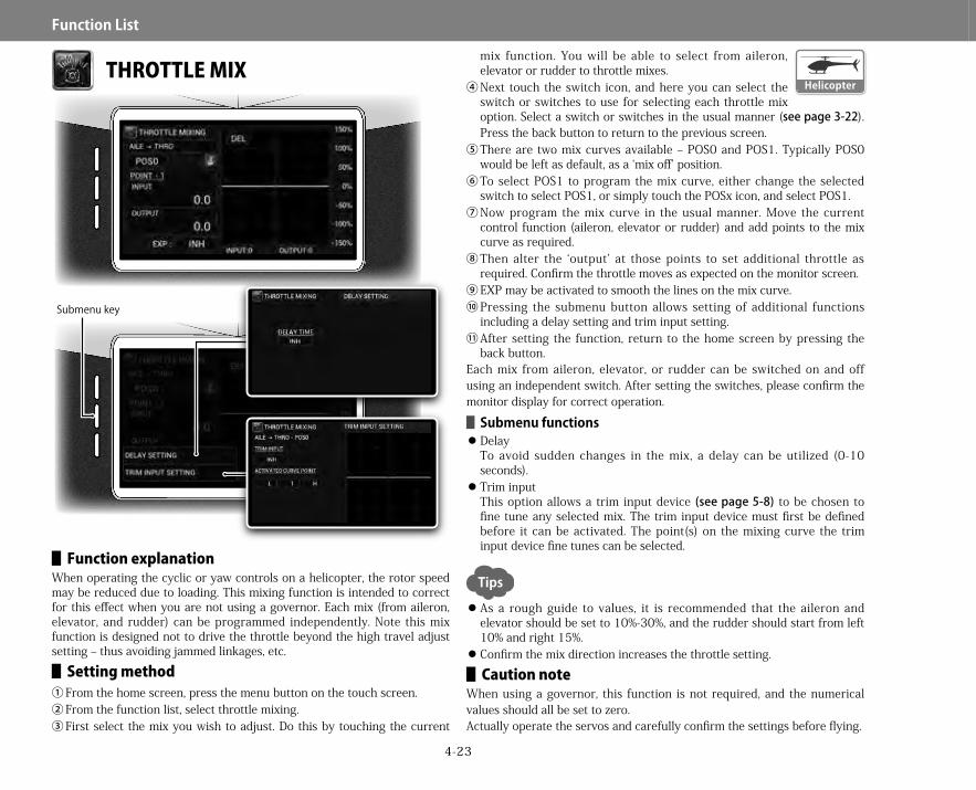
4-23
Function▋List
THROTTLE MIX
▋▋Function▋explanationWhen operating the cyclic or yaw controls on a helicopter, the rotor speed may be reduced due to loading. This mixing function is intended to correct for this effect when you are not using a governor. Each mix (from aileron, elevator, and rudder) can be programmed independently. Note this mix function is designed not to drive the throttle beyond the high travel adjust setting – thus avoiding jammed linkages, etc.▋▋Setting▋method
①From the home screen, press the menu button on the touch screen.②From the function list, select throttle mixing.③First select the mix you wish to adjust. Do this by touching the current
mix function. You will be able to select from aileron, elevator or rudder to throttle mixes.
④Next touch the switch icon, and here you can select the switch or switches to use for selecting each throttle mix option. Select a switch or switches in the usual manner (seepage3-22). Press the back button to return to the previous screen.
⑤There are two mix curves available – POS0 and POS1. Typically POS0 would be left as default, as a ‘mix off’ position.
⑥To select POS1 to program the mix curve, either change the selected switch to select POS1, or simply touch the POSx icon, and select POS1.
⑦Now program the mix curve in the usual manner. Move the current control function (aileron, elevator or rudder) and add points to the mix curve as required.
⑧Then alter the ‘output’ at those points to set additional throttle as required. Confirm the throttle moves as expected on the monitor screen.
⑨EXP may be activated to smooth the lines on the mix curve.⑩Pressing the submenu button allows setting of additional functions
including a delay setting and trim input setting.⑪After setting the function, return to the home screen by pressing the
back button.Each mix from aileron, elevator, or rudder can be switched on and off using an independent switch. After setting the switches, please confirm the monitor display for correct operation. ▋▋Submenu▋functions DelayTo avoid sudden changes in the mix, a delay can be utilized (0-10 seconds). Trim inputThis option allows a trim input device (seepage5-8) to be chosen to fine tune any selected mix. The trim input device must first be defined before it can be activated. The point(s) on the mixing curve the trim input device fine tunes can be selected.
As a rough guide to values, it is recommended that the aileron and elevator should be set to 10%-30%, and the rudder should start from left 10% and right 15%. Confirm the mix direction increases the throttle setting.▋▋Caution▋note
When using a governor, this function is not required, and the numerical values should all be set to zero.Actually operate the servos and carefully confirm the settings before flying.
Submenu key
Helicopter
Tips
28X_EN.indd 23 2015/02/27 13:42

4-24
Function▋List
FLAP SYSTEM
▋▋Function▋explanationThe flaps can be controlled in three stages using a switch. As well as setting the position for the flap servo(s), the aileron servo(s) (and flaperon servos if being used) can be freely adjusted as required. Further, the elevator and rudder can be adjusted so the model remains perfectly in trim as the flaps are deployed. The submenu contains a flap delay function to slow the transition of all control surfaces associated with this function. Additionally, trim input switches can be used to fine tune each of the flap system settings in flight.
▋▋Setting▋method①From the home screen, press the menu button on the touch screen.②From the function list, select flap system.
③First activate the function.④Next touch the switch icon, and here you can select the
switch or switches to use for selecting each flap system option. Select a switch or switches in the usual manner (seepage3-22). Note that if an analogue position switch is used (page5-7), it is possible to activate the flap system using the throttle stick. Press the back button to return to the previous screen.
⑤The display to the left of the switch icon indicates the current flap position. To set this function, either move the switch to select and then program each flap position in turn, or alternatively select the position to program by touching the current flap position indication and changing from here.
⑥Now set values for your desired flap position, aileron, elevator and rudder positions as required. In order to off-set the pitching action upon activating the flaps, it is possible to set an independent elevator trim position with each flap position. It is also possible to set a correction to roll and yaw in the same way.
⑦Pressing the submenu button allows setting of additional functions including a delay setting and trim input setting.
⑧After setting the function, return to the home screen by pressing the back button.▋▋Submenu▋functions DelayTo avoid sudden changes in the mix, a delay can be utilized (0-10 seconds). This smooth’s the model reaction as the flaps are lowered. Trim inputThis option allows a trim input device (seepage5-8) to be chosen to fine tune any selected mix. The trim input device must first be defined before it can be activated. By using the trim input, it is possible to change the amount of any selected flap system control surface deflection using a trim lever. Therefore, it is possible to easily adjust the flap system setup during flight.
This function is very handy for fine tuning model behavior when the flaps are deployed. The elevator can be trimmed to eliminate any pitch up or down tendency, as well as any roll or yaw induced with flap deployment.
▋▋Caution▋noteActually operate the servos and carefully confirm the settings before flying.
Submenu key
Airplane
Tips
28X_EN.indd 24 2015/02/27 13:42
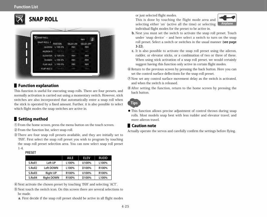
4-25
Function▋List
SNAP ROLL
▋▋Function▋explanationThis function is useful for executing snap rolls. There are four presets, and normally activation is carried out using a momentary switch. However, stick switches are also incorporated that automatically enter a snap roll when the stick is operated by a fixed amount. Further, it is also possible to select which flight modes the snap switches are active in.
▋▋Setting▋method①From the home screen, press the menu button on the touch screen.②From the function list, select snap roll.③There are four snap roll presets available, and they are initially set to
‘INH’. First select the snap roll preset you wish to program by touching the snap roll preset selection area. You can now select snap roll preset 1-4.
④Next activate the chosen preset by touching ‘INH’ and selecting ‘ACT’.⑤Next touch the switch icon. On this screen there are several selections to
be made.a. First decide if the snap roll preset should be active in all flight modes
or just selected flight modes.This is done by touching the flight mode area and selecting either ‘on’ (active all the time) or selecting individual flight modes for the preset to be active in.
b.Next you must set the switch to activate the snap roll preset. Touch under ‘snap device’ – and here select a switch to turn on the snap roll preset. Select a switch or switches in the usual manner (seepage3-22).
c. It is also possible to activate the snap roll preset using the aileron, rudder, or elevator sticks, or a combination of two or three of these. When using stick activation of a snap roll preset, we would certainly suggest having this function only active in certain flight modes.
⑥Return to the previous screen by pressing the back button. Here you can set the control surface deflections for the snap roll preset.
⑦Now set any control surface movement delay as the switch is activated, and when the switch is released.
⑧After setting the function, return to the home screen by pressing the back button.
This function allows precise adjustment of control throws during snap rolls. Most models snap best with less rudder and elevator travel, and more aileron travel.
▋▋Caution▋noteActually operate the servos and carefully confirm the settings before flying.
Airplane
PRESETAILE ELEV RUDD
S.Roll1 LeftUP L100% U100% L100%S.Roll2 LeftDOWN L100% D100% R100%S.Roll3 RightUP R100% U100% R100%S.Roll4 RightDOWN R100% D100% L100%
Tips
28X_EN.indd 25 2015/02/27 13:42
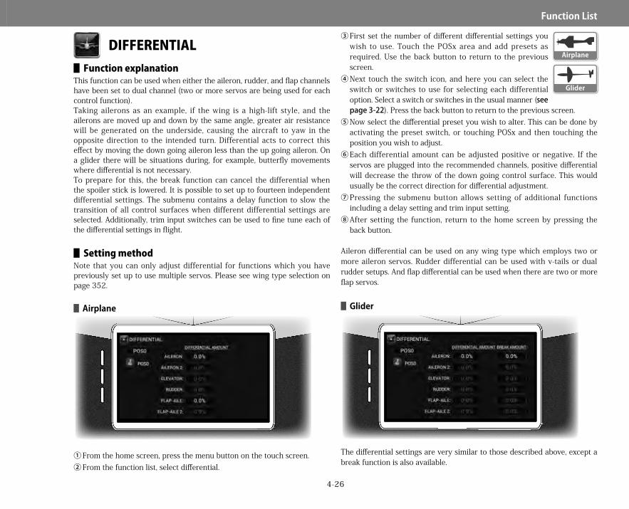
4-26
Function▋List
DIFFERENTIAL▋▋Function▋explanation
This function can be used when either the aileron, rudder, and flap channels have been set to dual channel (two or more servos are being used for each control function).Taking ailerons as an example, if the wing is a high-lift style, and the ailerons are moved up and down by the same angle, greater air resistance will be generated on the underside, causing the aircraft to yaw in the opposite direction to the intended turn. Differential acts to correct this effect by moving the down going aileron less than the up going aileron. On a glider there will be situations during, for example, butterfly movements where differential is not necessary.To prepare for this, the break function can cancel the differential when the spoiler stick is lowered. It is possible to set up to fourteen independent differential settings. The submenu contains a delay function to slow the transition of all control surfaces when different differential settings are selected. Additionally, trim input switches can be used to fine tune each of the differential settings in flight.
▋▋Setting▋methodNote that you can only adjust differential for functions which you have previously set up to use multiple servos. Please see wing type selection on page 352.
▋▋Airplane
①From the home screen, press the menu button on the touch screen.②From the function list, select differential.
③First set the number of different differential settings you wish to use. Touch the POSx area and add presets as required. Use the back button to return to the previous screen.
④Next touch the switch icon, and here you can select the switch or switches to use for selecting each differential option. Select a switch or switches in the usual manner (seepage3-22). Press the back button to return to the previous screen.
⑤Now select the differential preset you wish to alter. This can be done by activating the preset switch, or touching POSx and then touching the position you wish to adjust.
⑥Each differential amount can be adjusted positive or negative. If the servos are plugged into the recommended channels, positive differential will decrease the throw of the down going control surface. This would usually be the correct direction for differential adjustment.
⑦Pressing the submenu button allows setting of additional functions including a delay setting and trim input setting.
⑧After setting the function, return to the home screen by pressing the back button.
Aileron differential can be used on any wing type which employs two or more aileron servos. Rudder differential can be used with v-tails or dual rudder setups. And flap differential can be used when there are two or more flap servos.
▋▋Glider
The differential settings are very similar to those described above, except a break function is also available.
Airplane
Glider
28X_EN.indd 26 2015/02/27 13:42

4-27
Function▋List
▋BreakdifferentialfunctionThe spoiler stick position can be used to break (remove) any differential settings. The stick can be set to have no effect on differential (0%). You can set any position between 0% and 100% (full spoiler activation) for which the break to be activated, resulting in any differential settings being removed.
▋▋Submenu▋functions
DelayTo avoid sudden changes in the mix, a delay can be utilized (0-10 seconds). This smooth’s the model reaction as differential settings are changed. Trim inputThis option allows a trim input device (seepage5-8) to be chosen to fine tune any selected mix. The trim input device must first be defined before it can be activated. By using the trim input, it is possible to change the amount of any selected differential using a trim lever. Therefore, it is possible to easily adjust differential settings during flight.
Correct differential is important for optimal model performance. First equalize aileron up and down travels using travel adjust, and then fine tune the required differential using this function.
▋▋Caution▋noteActually operate the servos and carefully confirm the settings before flying.
Submenu key
Tips
28X_EN.indd 27 2015/02/27 13:42
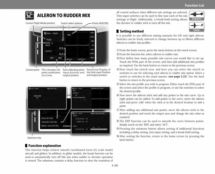
4-28
Function▋List
AILERON TO RUDDER MIX
▋▋Function▋explanationThis function helps achieve smooth coordinated turns for scale model aircraft and gliders. In addition, in glider models, the break function can be used to automatically turn off this mix when rudder or elevator operation is sensed. The submenu contains a delay function to slow the transition of
all control surfaces when different mix settings are selected. Trim input switches can be used to fine tune each of the mix settings in flight. Additionally, a break/hold setting allows the elevator or rudder stick to turn off the mix
▋▋Setting▋methodIt is possible to use different mixing amounts for left and right aileron. Switches can be freely selected to change between up to fifteen different aileron to rudder mix profiles.
①From the home screen, press the menu button on the touch screen.②From the function list, select aileron to rudder mix.③First define how many possible mix curves you would like to set up.
Touch the POSx part of the screen, and then add additional mix profiles as required. Use the back button to return to the previous screen.
④Next touch the switch icon, and here you can select the switch or switches to use for selecting each aileron to rudder mix option. Select a switch or switches in the usual manner (seepage3-22). Use the back button to return to the previous screen.
⑤Select the mix profile you wish to program. Either touch the POSx part of the screen and select the profile to program, or use the switches to select the desired profile.
⑥Now move the aileron stick and add any points to the mix curve. Up to eight points can be added. To add points to the curve, move the aileron stick and press ‘add’ when the stick is in the desired location to add a point.
⑦After adding any additional mix points, move the aileron stick to the desired position and touch the output area and change the mix value as required.
⑧The EXP function can be used to smooth the curve between points. Simply touch on the ‘INH’ and select ‘ACT’.
⑨Pressing the submenu button allows setting of additional functions including a delay setting, trim input setting, and a break/hold setting.
⑩After setting the function, return to the home screen by pressing the back button.
Submenu key
Points ADD/DELSwitch select optionsCurrent Flight Mode position
Current point Numerical Display of the Stick input Position and output position
This changes the point connections to a Curve.
Each adjusting point input position and output position
Airplane
Glider
28X_EN.indd 28 2015/02/27 13:42

4-29
Function▋List
▋▋Submenu▋functions DelayTo avoid sudden changes in the mix, a delay can be utilized (0-10 seconds). This smooth’s the model reaction if rudder mix settings are changed. Trim inputThis option allows a trim input device (seepage5-8) to be chosen to fine tune any selected mix. The trim input device must first be defined before it can be activated. By using the trim input, it is possible to change the amount of any selected rudder mix using a trim lever. Therefore, it is possible to easily adjust rudder mix settings during flight. BreakAs you move the elevator or rudder stick, the amount of mixing can be decreased.For example, if you set the elevator break to 30%, the amount of mix will decrease by up to 30% as you feed in more up elevator. And if you set the rudder break to 30%, the amount of mix will decrease by up to 30% as you feed in more rudder. HoldIf the elevator stick is moved beyond the designated position, the rudder will be fixed in its current position. If you go back to center, the rudder starts working again.Note, to inhibit these functions, touch the touch the selection area, and then touch and hold the value display till 'inh' is displayed.
Aileron to rudder mix is great on scale models and gliders for easing the workload on the pilot when performing coordinated turns. We would not however use this function on an aerobatic aircraft.
▋▋Caution▋noteActually operate the servos and carefully confirm the settings before flying.
AILERON TO FLAP MIX
▋▋Function▋explanationThis function mixes aileron operation to flaps. This allows maneuvering using the whole trailing edge of the wing as an aileron - minimizing the
Tips
Submenu key
Points ADD/DELSwitch select optionsCurrent Flight Mode position
Current point Numerical Display of the Stick input Position and output position
This changes the point connections to a Curve.
Each adjusting point input position and output position
Airplane
28X_EN.indd 29 2015/02/27 13:42

4-30
Function▋List
generation of air resistance when you wish to speed up the roll rate. The submenu contains a delay function to slow the transition of all control surfaces when different mix settings are selected. Trim input switches can be used to fine tune each of the mix settings in flight. Additionally, the aileron trim settings can be reflected in the flaps as desired
▋▋Setting▋methodFor this function to be active, the main wing type selected in the system menu (page5-17) must use at least two flap servos. If this is not the case, the following warning will be displayed:
It is possible to use different mixing amounts for left and right aileron. Switches can be freely selected to change between two different aileron to flap mix profiles.
①From the home screen, press the menu button on the touch screen.②From the function list, select aileron to flap mix.③Next touch the switch icon, and here you can select the switch or
switches to use for selecting each aileron to flap mix option. Select a switch or switches in the usual manner (seepage3-22). Use the back button to return to the previous screen.
④Select the mix profile you wish to program. Either touch the POSx part of the screen and select the profile to program, or use the switches to select the desired profile.
⑤Now move the aileron stick and add any points to the mix curve. Up to eight points can be added. To add points to the curve, move the aileron stick and press ‘add’ when the stick is in the desired location to add a point.
⑥After adding any additional mix points, move the aileron stick to the desired position and touch the output area and change the mix value as required.
⑦The EXP function can be used to smooth the curve between points. Simply touch on the ‘INH’ and select ‘ACT’.
⑧Pressing the submenu button allows setting of additional functions including a delay setting, trim input setting, and aileron trim include.
⑨After setting the function, return to the home screen by pressing the back button.
▋▋Submenu▋functions DelayTo avoid sudden changes in the mix, a delay can be utilized (0-10 seconds). This smooth’s the model reaction if aileron to flap mix settings are changed. Touch the delay time area on the screen, and input a delay time value. Press the back button to return to the previous screen. Trim inputThis option allows a trim input device (seepage5-8) to be chosen to fine tune any selected mix. The trim input device must first be defined before it can be activated. By using the trim input, it is possible to change the amount of any selected aileron to flap mix using a trim lever. Therefore, it is possible to easily adjust mix settings during flight. It is possible to select which point or points on the curve you would like the trim input to adjust. Aileron trim includeIncluding the aileron trim allows the flaps to move with the ailerons as the aileron trim is changed. This greatly decreases the drag of the wing if aileron trim changes are required.
▋▋Caution▋noteActually operate the servos and carefully confirm the settings before flying.
28X_EN.indd 30 2015/02/27 13:42

4-31
Function▋List
ELEVATOR TO FLAP MIX
▋▋Function▋explanationThis function mixes elevator operation to flaps, for so-called ‘air combat flaps’ (snap flaps). The submenu contains a delay function to slow the
transition of all control surfaces when different mix settings are selected. Trim input switches can be used to fine tune each of the mix settings in flight.
▋▋Setting▋methodFor this function to be active, the main wing type selected in the system menu (page5-17) must include a flap component. It is possible to use different mixing amounts for up and down aileron. Switches can be freely selected to change between two different elevator to flap mix profiles.
①From the home screen, press the menu button on the touch screen.②From the function list, select elevator to flap mix.③Next touch the switch icon, and here you can select the switch or
switches to use for selecting each elevator to flap mix option. Select a switch or switches in the usual manner (seepage3-22). Use the back button to return to the previous screen.
④Select the mix profile you wish to program. Either touch the POSx part of the screen and select the profile to program, or use the switches to select the desired profile.
⑤Now move the elevator stick and add any points to the mix curve. Up to eight points can be added. To add points to the curve, move the elevator stick and press ‘add’ when the stick is in the desired location to add a point.
⑥After adding any additional mix points, move the elevator stick to the desired position and touch the output area and change the mix value as required.
⑦The EXP function can be used to smooth the curve between points. Simply touch on the ‘INH’ and select ‘ACT’.
⑧Pressing the submenu button allows setting of additional functions including a delay setting and trim input setting.
⑨After setting the function, return to the home screen by pressing the back button.
▋▋Submenu▋functions DelayTo avoid sudden changes in the mix, a delay can be utilized (0-10 seconds). This smooth’s the model reaction if elevator to flap mix settings are changed. Trim inputThis option allows a trim input device (seepage5-8) to be chosen to
Submenu key
Points ADD/DELSwitch select optionsCurrent Flight Mode position
Current point Numerical Display of the Stick input Position and output position
This changes the point connections to a Curve.
Each adjusting point input position and output position
Airplane
28X_EN.indd 31 2015/02/27 13:42

4-32
Function▋List
fine tune any selected mix. The trim input device must first be defined before it can be activated. By using the trim input, it is possible to change the amount of any selected elevator to flap mix using a trim lever. Therefore, it is possible to easily adjust mix settings during flight. It is possible to select which point or points on the curve you would like the trim input to adjust.
This function is perfect to increase the maneuverability of a variety of models.
▋▋Caution▋noteActually operate the servos and carefully confirm the settings before flying.
Tips
28X_EN.indd 32 2015/02/27 13:42

4-33
Function▋List
RUDDER TO AILERON/ELEVATOR MIX
▋▋Function▋explanationThis function mixes rudder operation to the ailerons and elevators. This is convenient for removing biases in knife-edge flight. The mixing amounts from can be set separately for left and right as two independent settings. The submenu contains a delay function to slow the transition of all control
surfaces when different mix settings are selected. Trim input switches can be used to fine tune each of the mix settings in flight.
▋▋Setting▋methodSwitches can be freely selected to change between two different mix profiles.
①From the home screen, press the menu button on the touch screen.②From the function list, select rudder to elevator/aileron mix.③Select the mix you wish to adjust – either rudder to aileron, or rudder to
elevator. It is easy to switch between these two mixes by simply touching the screen and selecting the desired mix.
④Next touch the switch icon, and here you can select the switch or switches to use for selecting each mix option. Select a switch or switches in the usual manner (seepage3-22). Use the back button to return to the previous screen.
⑤Select the mix profile you wish to program. Either touch the POSx part of the screen and select the profile to program, or use the switches to select the desired profile.
⑥Now move the rudder stick and add any points to the mix curve. Up to eight points can be added. To add points to the curve, move the rudder stick and press ‘add’ when the stick is in the desired location to add a point.
⑦After adding any additional mix points, move the rudder stick to the desired position and touch the output area and change the mix value as required.
⑧The EXP function can be used to smooth the curve between points. Simply touch on the ‘INH’ and select ‘ACT’.
⑨Pressing the submenu button allows setting of additional functions including a delay setting and trim input setting.
⑩After setting the function, return to the home screen by pressing the back button.
Submenu key
Points ADD/DELSwitch select optionsCurrent Flight Mode positionMix select options
Current point Numerical Display of the Stick input Position and output position
This changes the point connections to a Curve.
Each adjusting point input position and output position
Airplane
28X_EN.indd 33 2015/02/27 13:42

4-34
Function▋List
▋▋Submenu▋functions DelayTo avoid sudden changes in the mix, a delay can be utilized (0-10 seconds). This smooth’s the model reaction if mix settings are changed. Trim inputThis option allows a trim input device (seepage5-8) to be chosen to fine tune any selected mix. The trim input device must first be defined before it can be activated. By using the trim input, it is possible to change the amount of any selected mix using a trim lever. Therefore, it is possible to easily adjust mix settings during flight. It is possible to select which point or points on the curve you would like the trim input to adjust.
This function is ideal for making a precision aerobatic model fly in a ‘pure’ manner with respect to yaw behavior.
▋▋Caution▋noteActually operate the servos and carefully confirm the settings before flying.
Tips
28X_EN.indd 34 2015/02/27 13:42

4-35
Function▋List
GEAR CONTROL
▋▋Function▋explanationThis function allows the precise mixing of retractable landing gear and landing gear doors (inner and outer) to be accomplished with ease. We recommend you set this function up with all servo linkages disconnected, so you can be sure of correct operation before connecting everything up.
▋▋Setting▋method①From the home screen, press the menu button on the touch screen.②From the function list, select gear control.③If you do not have appropriate servos assigned (seeCHANNELSETTINGS,
page5-15), the following warning will be displayed.④ Assign channels for all necessary functions - landing gears or covers (gear
doors) using the channel setting menu (page5-15).⑤The function is initially inhibited. So first touch ‘inh’ and then select the
required mode of operation.a. Single mode: In this mode up and down gear actuation follows the
same sequenceb.Separate mode: In this mode up and down gear and
door action can be different.c. Curve movement can be made slowly. Activating exp
makes the curve smooth.'Step' is for a quick movement. Operation time is the servo speed.
d.Set the time required from moving from the left to right of the graph.e.To add a point, press the triangular arrow on the left and right sides
of each graph. That changes the position of the blue line. Move the blue line to the desired point and press the 'add' key..
f. Switch select - allows the appropriate switch to be defined.▋▋Point▋setting▋
To set the output value at each point, tap the adjusting point display (“POINT-L, etc.) and select the point to be set from the submenu. Then, tap the output position of the adjusting point and set the value.
This function is ideal for correctly sequencing the operation of complex retractable landing gear and gear doors. Take your time to set the function up as accurately as you can.
▋▋Caution▋noteActually operate the servos and carefully confirm the settings before flying.
Stick output PositionStick output PositionCurrent point
Points ADD/DEL
This changes the point connections to a Curve.
Curve or Step
Time set options
Switch select options
Airplane
Tips
28X_EN.indd 35 2015/02/27 13:42

4-36
Function▋List
OUTPUT CURVE
▋▋Function▋explanationThis function is used to correct for individual servo characteristic to equalize the travel of each control surface. It is available on all 16 proportional channels, but particularly useful when using multiple aileron, elevator, and flap servos. It is also useful when more than two servos are used on a control surface. The submenu contains trim input setting can be used to fine tune each of the output curves in flight.
▋▋Setting▋method▋▋Airplane
①From the home screen, press the menu button on the touch screen.
②From the function list, select output curve.③Select the servo output curve you wish to modify. It is
possible to fine tune the output curve for each of the 16 proportional channels. Touch the channel selection area and select the channel to modify.
④Add points to the output curve. Often you would only need to add points at maximum control deflection for each channel.
⑤Now modify the output curve as required.⑥You can activate the EXP function to smooth the response curve between
points.⑦Pressing the submenu button allows setting of additional functions
including trim input setting.⑧After setting the function, return to the home screen by pressing the
back button.
▋▋Submenu▋functions Trim inputThis option allows a trim input device (seepage5-8) to be chosen to fine tune any selected output curve. The trim input device must first be defined before it can be activated. By using the trim input, it is possible to change the output curve using a trim lever. Therefore, it is possible to easily adjust the settings during flight. It is possible to select which point or points on the curve you would like the trim input to adjust.
For each servo, eight points can be adjusted, along with the high and low points. This allows not only exact matching of the servo neutrals, but also matching of additional points including full travel. By using the EXP function, it is possible to smooth the transition between points on the curve.
▋▋Caution▋noteActually operate the servos and carefully confirm the settings before flying.
Submenu key
Points ADD/DELCurrent channel
Current point Numerical Display of the Stick input Position and output position
This changes the point connections to a Curve.
Each adjusting point input position and output position
Glider
Helicopter
Airplane
Tips
28X_EN.indd 36 2015/02/27 13:42

4-37
Function▋List
FLAP RATE
▋▋Function▋explanationThis function sets the maximum up and down movement of the flap control surface angles independently in each flight mode when using the flap lever. The submenu contains a delay function to slow the transition of all control surfaces when different mix settings are selected. Trim input switches can
be used to fine tune each of the mix settings in flight.
▋▋Setting▋method①From the home screen, press the menu button on the touch screen.②From the function list, select flap rate.③Flap rates can be set for flap, flap 2, flaperon, flaperon 2 – touch the
channel selector, and select the function you wish to adjust.④Next select how many different profiles you would like for this function.
Touch the profile area and add profiles as necessary. Use the back button to return to the previous screen.
⑤Next touch the switch icon, and here you can select the switch or switches to use for selecting each flap rate option. Select a switch or switches in the usual manner (seepage3-22). Use the back button to return to the previous screen.
⑥Select the mix profile you wish to program. Either touch the POSx part of the screen and select the profile to program, or use the switches to select the desired profile.
⑦Now move the flap lever and add any points to the mix curve as required. Up to eight points can be added. To add points to the curve, move the lever and press ‘add’ when the cursor is in the desired location to add a point. Often it is fine to just use the default low and high points.
⑧After adding any additional mix points, move the flap lever to the desired position and touch the output area and change the flap rate as required.
⑨The EXP function can be used to smooth the curve between points. Simply touch on the ‘INH’ and select ‘ACT’.
⑩Pressing the submenu button allows setting of additional functions including a delay setting and trim input setting.
⑪After setting the function, return to the home screen by pressing the back button.
Initially, the flap rate is set to 0% (default for each flight mode). To change this setting, adjust the numeric values. The default lever for this function is the right side flap lever. This can be changed in the channel setting menu (page5-15) – the lever input is that assigned to flap.
Submenu key
Points ADD/DELSwitch select optionsCurrent Flight Mode positionCurrent channel
Current point Numerical Display of the Stick input Position and output position
This changes the point connections to a Curve.
Each adjusting point input position and output position
Glider
28X_EN.indd 37 2015/02/27 13:42
4-38
Function▋List
▋▋Submenu▋functions DelayTo avoid sudden changes in the mix, a delay can be utilized (0-10 seconds). This smooth’s the model reaction if mix settings are changed. Trim inputThis option allows a trim input device (seepage5-8) to be chosen to fine tune any selected mix. The trim input device must first be defined before it can be activated. By using the trim input, it is possible to change the amount of any selected mix using a trim lever. Therefore, it is possible to easily adjust mix settings during flight. It is possible to select which point or points on the curve you would like the trim input to adjust.
When operating a competition aircraft where there is concern regarding mistaken operation of the flap switches or levers, set the outputs to zero. Flap operation can still be carried out using other mixing – for example using the camber system.
▋▋Caution▋noteActually operate the servos and carefully confirm the settings before flying.
Tips
28X_EN.indd 38 2015/02/27 13:42

4-39
Function▋List
MOTOR SYSTEM
▋▋Function▋explanationThis function is used to switch off (hold) the motor channel using a switch. By using the delay function, it is possible to smoothly change motor speed (the speed controller must have a linear transition to correctly use this function).
▋▋Setting▋methodIn order to use this function, it is necessary to set a motor channel in the channel setting menu (system menu). Here you can also define the control lever for the motor (seepage5-15). If you have not defined a motor channel, the following warning will be displayed when you enter this function.①From the home screen, press the menu button on the touch screen.②From the function list, select motor system.③First select a switch to activate the hold function. Touch the switch icon,
and here you can select the switch or switches to use for selecting each option. Select a switch or switches in the usual manner (seepage3-22). Use the back button to return to the previous screen.
④Next select the hold position. This would typically be motor off, with a value of 0%. Touch the appropriate area of the screen and set the value here.
⑤Now set the hold delay. This function slows the throttle change rate between high and low settings. The up arrow indicates the speed to increase throttle, and the down arrow the speed to decrease throttle.
Delays form 0-10 seconds are possible.⑥After setting the function, return to the home screen by
pressing the back button.
▋▋Caution▋noteBe sure to set the ‘warning’ function in the system list and be aware of the motor starting unexpectedly.It is very easy to accidently turn on a switch and the motor start, and not immediately realize why. Always program this function with the motor disconnected. Finally run the motor and carefully confirm the settings before flight.
Glider
28X_EN.indd 39 2015/02/27 13:42
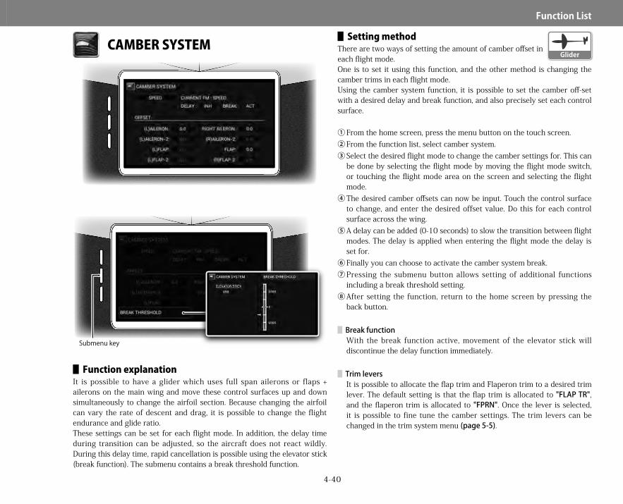
4-40
Function▋List
CAMBER SYSTEM
▋▋Function▋explanationIt is possible to have a glider which uses full span ailerons or flaps + ailerons on the main wing and move these control surfaces up and down simultaneously to change the airfoil section. Because changing the airfoil can vary the rate of descent and drag, it is possible to change the flight endurance and glide ratio.These settings can be set for each flight mode. In addition, the delay time during transition can be adjusted, so the aircraft does not react wildly. During this delay time, rapid cancellation is possible using the elevator stick (break function). The submenu contains a break threshold function.
▋▋Setting▋methodThere are two ways of setting the amount of camber offset in each flight mode.One is to set it using this function, and the other method is changing the camber trims in each flight mode.Using the camber system function, it is possible to set the camber off-set with a desired delay and break function, and also precisely set each control surface.
①From the home screen, press the menu button on the touch screen.②From the function list, select camber system.③Select the desired flight mode to change the camber settings for. This can
be done by selecting the flight mode by moving the flight mode switch, or touching the flight mode area on the screen and selecting the flight mode.
④The desired camber offsets can now be input. Touch the control surface to change, and enter the desired offset value. Do this for each control surface across the wing.
⑤A delay can be added (0-10 seconds) to slow the transition between flight modes. The delay is applied when entering the flight mode the delay is set for.
⑥Finally you can choose to activate the camber system break.⑦Pressing the submenu button allows setting of additional functions
including a break threshold setting.⑧After setting the function, return to the home screen by pressing the
back button.
▋BreakfunctionWith the break function active, movement of the elevator stick will discontinue the delay function immediately.
▋TrimleversIt is possible to allocate the flap trim and Flaperon trim to a desired trim lever. The default setting is that the flap trim is allocated to "FLAPTR", and the flaperon trim is allocated to "FPRN". Once the lever is selected, it is possible to fine tune the camber settings. The trim levers can be changed in the trim system menu (page5-5).
Submenu key
Glider
28X_EN.indd 40 2015/02/27 13:42

4-41
Function▋List
▋▋Submenu▋functions Break thresholdThe break threshold setting defines the elevator stick position at which the delay function is deactivated.
To prevent unnoticed changes of the camber trim position that has been set in each flight mode, the sensitivity of the camber trim levers can be set to zero.After fine tuning the camber trim settings, the FLAP and FPRM trim steps in the trim system screen (page5-5) can be set to zero. By doing so, even though the trim lever will not actually operate, the set positions will remain memorized.
▋▋Caution▋noteActually operate the servos and carefully confirm the settings before flying.
BRAKE SYSTEM
▋▋Function▋explanationThis function creates air brakes to slow the model using a combination of any of the following controls: spoilers, ailerons, and/or flaps.The function is also known as butterfly mixing or crow mixing. When the spoiler stick is lowered, the flaps will lower and the ailerons will be lifted, and spoilers deployed if available. Looking from the front of the aircraft you
Tips
Submenu key
Points ADD/DELSwitch select optionsCurrent Flight Mode position
Current point Numerical Display of the Stick input Position and output positionThis changes the
point connections to a Curve.
Each adjusting point input position and output position
Speed
Current channelGlider
28X_EN.indd 41 2015/02/27 13:42

4-42
Function▋List
will see the whole wing will no longer generate lift, and will have a huge amount of drag. A dead band can be set to prevent unintentional operation if the stick is just moved a small amount.In addition, trim correction provided by the elevator can be finely adjusted to the air brake position using an adjustable mixing curve. The submenu contains a trim input setting can be used to fine tune each of the brake settings in flight.
▋▋Setting▋method①From the home screen, press the menu button on the touch screen.②From the function list, select brake system.③First select a switch to change between POS0 and POS1. Touch the
switch icon, and here you can select the switch or switches to use for selecting each option. Select a switch or switches in the usual manner (seepage3-22). Use the back button to return to the previous screen.
④Touch on the function select area, and select ‘start position’. ⑤Here you can set the start position (or dead band at the start of spoiler
stick travel) for brake activation. Touch on the position area, and change the start position as desired. We would recommend using a value of 90-95.
⑥Touch on the function select area, and select ‘spoiler’. ⑦On this screen you are able to adjust spoiler operation as the spoiler
stick is moved. You are able to set two different spoiler profiles. First touch the switch icon and select the switches to use to activate the different profiles.To adjust each profile, either select the desired profile using the assigned switch, or touch the profile area on the screen and select from here.
⑧Up to eight user definable points can be added to the spoiler response curve. Simply move the spoiler stick and touch add. You will see you are able to delete points by touching delete.The curve output at each point can be adjusted by moving the spoiler stick to the desired point and touching on ‘output’ and making adjustments as required.
⑨EXP can be activated which will smooth the defined response curve.⑩The speed of spoiler movement can also be slowed – touch on speed and
enter a value between 0-10 seconds. This modifies the speed of spoiler response in both directions.
⑪Again touch on the function select area, and select ‘spoiler to elevator’. ⑫On this screen you are able to adjust elevator compensation as the
spoiler stick is moved.
You are able to set two different elevator compensation profiles. First touch the switch icon and select the switches to use to activate the different profiles.To adjust each profile, either select the desired profile using the assigned switch, or touch the profile area on the screen and select from here.
⑬Up to eight user definable points can be added to the elevator compensation response curve. Simply move the spoiler stick and touch add. You will see you are able to delete points by touching delete. The curve output at each point can be adjusted by moving the spoiler stick to the desired point and touching on ‘output’ and making adjustments as required.
⑭EXP can be activated which will smooth the defined response curve.⑮The speed of elevator movement can also be slowed – touch on speed
and enter a value between 0-10 seconds. This modifies the speed of elevator response in both directions.
⑯Again touch on the function select area, and select ‘spoiler to flap’. ⑰On this screen you are able to adjust flap operation as the spoiler stick is
moved. You are able to set two different flap profiles.First touch the switch icon and select the switches to use to activate the different profiles.To adjust each profile, either select the desired profile using the assigned switch, or touch the profile area on the screen and select from here.
⑱Up to eight user definable points can be added to the flap response curve. Simply move the spoiler stick and touch add. You will see you are able to delete points by touching delete. The curve output at each point can be adjusted by moving the spoiler stick to the desired point and touching on ‘output’ and making adjustments as required.
⑲EXP can be activated which will smooth the defined response curve.⑳The speed of flap movement can also be slowed – touch on speed and
enter a value between 0-10 seconds. This modifies the speed of flap response in both directions.
㉑Touch on the function select area, and select ‘spoiler to flaperon’. ㉒On this screen you are able to adjust flaperon operation as the spoiler
stick is moved. You are able to set two different spoiler profiles. First touch the switch icon and select the switches to use to activate the different profiles. To adjust each profile, either select the desired profile using the assigned switch, or touch the profile area on the screen and select from here.
㉓Up to eight user definable points can be added to the spoiler response curve. Simply move the spoiler stick and touch add. You will see you are
28X_EN.indd 42 2015/02/27 13:42
4-43
Function▋List
able to delete points by touching delete. The curve output at each point can be adjusted by moving the spoiler stick to the desired point and touching on ‘output’ and making adjustments as required.
㉔EXP can be activated which will smooth the defined response curve.㉕The speed of flaperon movement can also be slowed – touch on speed
and enter a value between 0-10 seconds.This modifies the speed of spoiler response in both directions.
㉖Spoiler to flap 2 and spoiler to flaperon 2 can be set in the same manner if present.
㉗Pressing the submenu button allows setting of additional functions including trim input setting.
㉘After setting the function, return to the home screen by pressing the back button.
▋▋Submenu▋functions Trim inputThis option allows a trim input device (seepage5-8) to be chosen to fine tune any selected mix. The trim input device must first be defined before it can be activated. By using the trim input, it is possible to change the amount of any selected mix using a trim lever. Therefore, it is possible to easily adjust mix settings during flight. It is possible to select which point or points on the curve you would like the trim input to adjust.Trim input settings are available for each of the brake system curves. This is particularly useful for the spoiler to elevator mix, and allows fine turning of this function during flight.
In quick summary: The spoiler stick is used to control the brake function. It can be linked to spoilers, flaps and/or flaperons. As more brake is added, it is possible to precisely adjust the elevator mix so the model does not stall.
▋▋Caution▋noteWhen this function is fully operated, the servos will move a considerable amount. At this time, care is required to avoid jamming any of the control surfaces.Use the limit adjust function to apply limits to servo movement to avoid damaging the control surfaces or servos.
After programming these settings, operate the servos and carefully confirm each of the flight mode settings before flying.
Tips
28X_EN.indd 43 2015/02/27 13:42

4-44
Function▋List
FLAPERON MIX
▋▋Function▋explanationThis function allows flaperon mixing.
‘Aileron to flap’ (and aileron to flap 2):This mixes from aileron to flap, to use the flaps as ailerons - therefore the roll rate can be increased with less drag.
‘Flap to flaperon’:This mixes from flap to aileron, to use the ailerons as flaps. ‘Flap to elevator’:This mixes from flap to elevator, to correct pitch variation caused by flap extension.
The submenu contains a delay function to slow the transition of all control surfaces when different mix settings are selected.Trim input switches can be used to fine tune each of the mix settings in flight.Additionally, the aileron trim settings can be reflected in the flaps where appropriate.
▋▋Setting▋method▋Flaptoflaperon
①From the home screen, press the menu button on the touch screen.②From the function list, select flaperon mix.③Touch on the function select area, and select ‘flap to flaperon’. ④On this screen you are able to adjust how the ailerons respond to flap
operation. You are able to set up to 15 different mix profiles. Touch the profile area of the screen and add or remove profiles as necessary.
⑤Next touch the switch icon and select the switches to use to activate the different profiles. seepage3-22.
⑥To adjust each profile, either select the desired profile using the assigned switch, or touch the profile area on the screen and select from here.
⑦Up to eight user definable points can be added to the flap to flaperon response curve. Simply move the flap lever and touch add.You will see you are able to delete points by touching delete.The curve output at each point can be adjusted by moving the spoiler stick to the desired point and touching on ‘output’ and making adjustments as required.
⑧EXP can be activated which will smooth the defined response curve.⑨Pressing the submenu button allows setting of additional functions
including a delay setting and trim input setting.⑩After setting the function, return to the home screen by pressing the
back button. If you are using 4 ailerons, flap to flaperon 2 mix is also available.
▋Ailerontoflap①From the home screen, press the menu button on the touch screen.
Submenu key
Points ADD/DELSwitch select optionsCurrent Flight Mode positionMix select options
Current point Numerical Display of the Stick input Position and output position
This changes the point connections to a Curve.
Each adjusting point input position and output position
Glider
28X_EN.indd 44 2015/02/27 13:42

4-45
Function▋List
②From the function list, select flaperon mix.③Touch on the function select area, and select ‘aileron to flap’. ④On this screen you are able to adjust how the flaps respond to aileron
operation. You are able to set up to 15 different mix profiles.Touch the profile area of the screen and add or remove profiles as necessary.
⑤Next touch the switch icon and select the switches to use to activate the different profiles. To adjust each profile, either select the desired profile using the assigned switch, or touch the profile area on the screen and select from here.
⑥Up to eight user definable points can be added to the aileron to flap response curve. Simply move the aileron stick and touch add. You will see you are able to delete points by touching delete.The curve output at each point can be adjusted by moving the spoiler stick to the desired point and touching on ‘output’ and making adjustments as required.
⑦EXP can be activated which will smooth the defined response curve.⑧Pressing the submenu button allows setting of additional functions
including a delay setting and trim input setting.Additionally, it is possible to have the aileron trim move only the ailerons or for the aileron trim to also move the flaps using the aileron trim include function.
⑨After setting the function, return to the home screen by pressing the back button. If you are using 4 flaps, aileron to flap 2 mix is also available.
▋Flaptoelevator①From the home screen, press the menu button on the touch screen.②From the function list, select flaperon mix.③Touch on the function select area, and select ‘elevator to flap’. ④On this screen you are able to adjust how the elevator respond to flap
operation. You are able to set up to 15 different mix profiles.Touch the profile area of the screen and add or remove profiles as necessary. Next touch the switch icon and select the switches to use to activate the different profiles.To adjust each profile, either select the desired profile using the assigned switch, or touch the profile area on the screen and select from here.
⑤Up to eight user definable points can be added to the elevator to flap response curve. Simply move the flap lever and touch add. You will see you are able to delete points by touching delete.
The curve output at each point can be adjusted by moving the flap lever to the desired point and touching on ‘output’ and making adjustments as required.
⑥EXP can be activated which will smooth the defined response curve.⑦Pressing the submenu button allows setting of additional functions
including a delay setting and trim input setting.⑧After setting the function, return to the home screen by pressing the
back button.
▋▋Submenu▋functions DelayTo avoid sudden changes in the mix, a delay can be utilized (0-10 seconds). This smooth’s the model reaction if flaperon mix settings are changed. Trim inputThis option allows a trim input device (seepage5-8) to be chosen to fine tune any selected mix. The trim input device must first be defined before it can be activated. By using the trim input, it is possible to change the amount of any selected flaperon mix using a trim lever. Therefore, it is possible to easily adjust mix settings during flight. It is possible to select which point or points on the curve you would like the trim input to adjust. Include aileron trim (aileron to flap or aileron to flap2 mix only)Including the aileron trim allows the flaps to move with the ailerons as the aileron trim is changed. It is possible to have the aileron trim move only the ailerons (inh) or for the aileron trim to also move the flaps (act). This greatly decreases the drag of the wing if aileron trim changes are required.
The initial setting for the flap rate is set to 0%. When mixing from flaps, set the flap travel amount using the flap rate first, before setting this mix.
▋▋Caution▋noteActually operate the servos and carefully confirm the settings before flying.
Tips
28X_EN.indd 45 2015/02/27 13:42
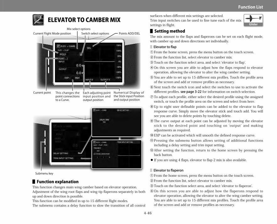
4-46
Function▋List
ELEVATOR TO CAMBER MIX
▋▋Function▋explanationThis function changes main wing camber based on elevator operation. Adjustment of the wing root flaps and wing tip flaperons separately in both up and down direction is possible.This function can be modified in up to 15 different flight modes.The submenu contains a delay function to slow the transition of all control
surfaces when different mix settings are selected.Trim input switches can be used to fine tune each of the mix settings in flight.
▋▋Setting▋methodThe mix amount to the flaps and flaperons can be set on each flight mode, with camber up and down directions set individually.
▋Elevatortoflap①From the home screen, press the menu button on the touch screen.②From the function list, select elevator to camber mix.③Touch on the function select area, and select ‘elevator to flap’.④On this screen you are able to adjust how the flaps respond to elevator
operation, allowing the elevator to alter the wing camber setting. ⑤You are able to set up to 15 different mix profiles. Touch the profile area
of the screen and add or remove profiles as necessary.⑥Next touch the switch icon and select the switches to use to activate the
different profiles. seepage3-22 for information on switch selection.⑦To adjust each profile, either select the desired profile using the assigned
switch, or touch the profile area on the screen and select from here.⑧Up to eight user definable points can be added to the elevator to flap
response curve. Simply move the elevator stick and touch add. You will see you are able to delete points by touching delete.
⑨The curve output at each point can be adjusted by moving the elevator stick to the desired point and touching on ‘output’ and making adjustments as required.
⑩EXP can be activated which will smooth the defined response curve.⑪Pressing the submenu button allows setting of additional functions
including a delay setting and trim input setting.⑫After setting the function, return to the home screen by pressing the
back button. If you are using 4 flaps, elevator to flap 2 mix is also available.
▋Elevatortoflaperon①From the home screen, press the menu button on the touch screen.②From the function list, select elevator to camber mix.③Touch on the function select area, and select ‘elevator to flaperon’. ④On this screen you are able to adjust how the flaperons respond to
elevator operation, allowing the elevator to alter the wing camber setting. You are able to set up to 15 different mix profiles. Touch the profile area of the screen and add or remove profiles as necessary.
Submenu key
Points ADD/DELSwitch select optionsCurrent Flight Mode positionMix select options
Current point Numerical Display of the Stick input Position and output position
This changes the point connections to a Curve.
Each adjusting point input position and output position
Glider
28X_EN.indd 46 2015/02/27 13:42

4-47
Function▋List
Next touch the switch icon and select the switches to use to activate the different profiles. To adjust each profile, either select the desired profile using the assigned switch, or touch the profile area on the screen and select from here.
⑤Up to eight user definable points can be added to the elevator to flaperon response curve. Simply move the elevator stick and touch add. You will see you are able to delete points by touching delete.The curve output at each point can be adjusted by moving the elevator stick to the desired point and touching on ‘output’ and making adjustments as required.
⑥EXP can be activated which will smooth the defined response curve.⑦Pressing the submenu button allows setting of additional functions
including a delay setting and trim input setting.⑧After setting the function, return to the home screen by pressing the
back button. If you are using 4 ailerons, elevator to aileron 2 mix is also available.
▋▋Submenu▋functions DelayTo avoid sudden changes in the mix, a delay can be utilized (0-10 seconds). This smooth’s the model reaction if mix settings are changed. Trim inputThis option allows a trim input device (seepage5-8)to be chosen to fine tune any selected mix. The trim input device must first be defined before it can be activated.By using the trim input, it is possible to change the amount of any selected elevator to camber mix using a trim lever. Therefore, it is possible to easily adjust mix settings during flight. It is possible to select which point or points on the curve you would like the trim input to adjust.
Elevator to camber mix creates so called snap flaps and can be used on aircraft with main wings that have at least 2 aileron servos. To maximize stability, have less mix to the wing tip ailerons, and more mix at the wing root flaps.
▋▋Caution▋noteActually operate the servos and carefully confirm the settings before flying.
RUDDER TO SPOILER MIX
▋▋Function▋explanationThis function emulates (or augments) rudder operation using spoilers on aircraft equipped with dual spoilers. This yaw method is also known as drag rudder.According to the rudder stick operation, the left and right spoilers extend and retract. It is possible to program up to 14 different mix profiles.
Tips
Submenu key
Points ADD/DELSwitch select optionsCurrent Flight Mode position
Current point Numerical Display of the Stick input Position and output position
This changes the point connections to a Curve.
Each adjusting point input position and output position
Glider
28X_EN.indd 47 2015/02/27 13:42

4-48
Function▋List
The submenu contains a delay function to slow the transition of all control surfaces when different mix settings are selected. Trim input switches can be used to fine tune each of the mix settings in flight.
▋▋Setting▋methodIt is essential to set up dual spoilers in the wing type settings (page5-17) for this function to be active. If you have not activated dual spoilers, the following warning will be displayed.①From the home screen, press the menu button on the touch screen.②From the function list, select rudder to spoiler mix.③On this screen you are able to adjust how the spoilers respond to rudder
operation, allowing the rudder to alter the spoiler positions. You are able to set up to 14 different mix profiles. Touch the profile area of the screen and add or remove profiles as necessary.
④Next touch the switch icon and select the switches to use to activate the different profiles. seepage3-22 for information on switch selection.
⑤To adjust each profile, either select the desired profile using the assigned switch, or touch the profile area on the screen and select from here.
⑥Up to eight user definable points can be added to the rudder to spoiler response curve. Simply move the rudder stick and touch add. You will see you are able to delete points by touching delete.
⑦The curve output at each point can be adjusted by moving the elevator stick to the desired point and touching on ‘output’ and making adjustments as required.
⑧EXP can be activated which will smooth the defined response curve.⑨Pressing the submenu button allows setting of additional functions
including a delay setting and trim input setting.⑩After setting the function, return to the home screen by pressing the
back button.
▋▋Submenu▋functions DelayTo avoid sudden changes in the mix, a delay can be utilized (0-10 seconds). This smooth’s the model reaction if mix settings are changed. Trim inputThis option allows a trim input device (seepage5-8) to be chosen to fine tune any selected mix.The trim input device must first be defined before it can be activated.By using the trim input, it is possible to change the amount of any selected rudder to spoiler mix using a trim lever. Therefore, it is possible
to easily adjust mix settings during flight.It is possible to select which point or points on the curve you would like the trim input to adjust.
On a large large-sized aircraft equipped with spoilers on its main wing, this form of augmented yaw control using spoilers is very effective.
▋▋Caution▋noteActually operate the servos and carefully confirm the settings before flying.
Tips
28X_EN.indd 48 2015/02/27 13:42
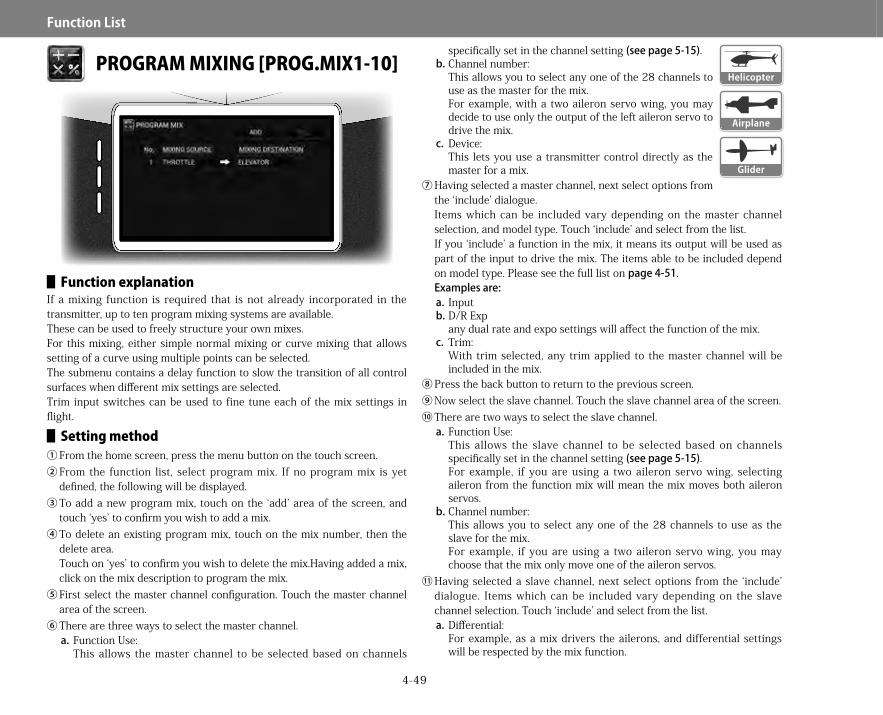
4-49
Function▋List
PROGRAM MIXING [PROG.MIX1-10]
▋▋Function▋explanationIf a mixing function is required that is not already incorporated in the transmitter, up to ten program mixing systems are available.These can be used to freely structure your own mixes.For this mixing, either simple normal mixing or curve mixing that allows setting of a curve using multiple points can be selected.The submenu contains a delay function to slow the transition of all control surfaces when different mix settings are selected.Trim input switches can be used to fine tune each of the mix settings in flight.
▋▋Setting▋method①From the home screen, press the menu button on the touch screen.②From the function list, select program mix. If no program mix is yet
defined, the following will be displayed.③To add a new program mix, touch on the ‘add’ area of the screen, and
touch ‘yes’ to confirm you wish to add a mix.④To delete an existing program mix, touch on the mix number, then the
delete area.Touch on ‘yes’ to confirm you wish to delete the mix.Having added a mix, click on the mix description to program the mix.
⑤First select the master channel configuration. Touch the master channel area of the screen.
⑥There are three ways to select the master channel. a. Function Use:
This allows the master channel to be selected based on channels
specifically set in the channel setting (seepage5-15).b.Channel number:
This allows you to select any one of the 28 channels to use as the master for the mix.For example, with a two aileron servo wing, you may decide to use only the output of the left aileron servo to drive the mix.
c. Device:This lets you use a transmitter control directly as the master for a mix.
⑦Having selected a master channel, next select options from the ‘include’ dialogue.Items which can be included vary depending on the master channel selection, and model type. Touch ‘include’ and select from the list.If you ‘include’ a function in the mix, it means its output will be used as part of the input to drive the mix. The items able to be included depend on model type. Please see the full list on page4-51.Examplesare:a. Inputb.D/R Exp
any dual rate and expo settings will affect the function of the mix.c. Trim:
With trim selected, any trim applied to the master channel will be included in the mix.
⑧Press the back button to return to the previous screen.⑨Now select the slave channel. Touch the slave channel area of the screen.⑩There are two ways to select the slave channel.
a. Function Use:This allows the slave channel to be selected based on channels specifically set in the channel setting (seepage5-15).For example, if you are using a two aileron servo wing, selecting aileron from the function mix will mean the mix moves both aileron servos.
b.Channel number:This allows you to select any one of the 28 channels to use as the slave for the mix.For example, if you are using a two aileron servo wing, you may choose that the mix only move one of the aileron servos.
⑪Having selected a slave channel, next select options from the ‘include’ dialogue. Items which can be included vary depending on the slave channel selection. Touch ‘include’ and select from the list.a.Differential:
For example, as a mix drivers the ailerons, and differential settings will be respected by the mix function.
Glider
Helicopter
Airplane
28X_EN.indd 49 2015/02/27 13:42

4-50
Function▋List
⑫Press the back button to return to the previous screen.⑬Next select if you wish to use a normal mix or the curve mix function.
The normal mix only allows adjustment of the endpoints of the mixing function. A curve mix allows the degree of mix to be changed based on the position of the master channel.Touch on the mix type (normal or curve) to select the type of mix you wish to use.
⑭Next touch on the switch icon to select a switch to use for activating the mix. seepage3-22 for information on switch selection.
⑮Each mix allows two different mix profiles.⑯Normal mix:
a.The total mix in each profile is set by touching the required profile (POS 0 or 1).
b.Move the master channel to each extreme of travel, and set the total mix required. If the master channel is in the center of travel, the mix in both directions can be adjusted simultaneously.
c. Often POS 0 would be set to 0% mix values (mix off), and POS 1 would have mix values entered (mix active).
⑰Curve mix:
Submenu key
Switch select options
Mixing Offset on reference point
Mix profiles Master channel Slave channel
Mixing value
Submenu key
Points ADD/DEL
Switch select options
Current point Numerical Display of the Stick input Position and output position
This changes the point connections to a Curve.
Each adjusting point input position and output position
Current Flight Mode position Mix profiles
Master channel
Slave channel
28X_EN.indd 50 2015/02/27 13:42

4-51
Function▋List
a.On this screen you are able to adjust how the mix responds in a very exact manner. You are able to set two different mix profiles.
b.Touch the switch icon and select the switches to use to activate the different profiles.
c. To adjust each profile, either select the desired profile using the assigned switch, or touch the profile area on the screen and select from here.
d.Up to eight user definable points can be added to the mix curve. Simply move the master control, and touch add. You will see you are able to delete points by touching delete.
e.The curve output at each point can be adjusted by moving the master control to the desired point and touching on ‘output’ and making adjustments as required.
f. EXP can be activated which will smooth the defined response curve.⑱Pressing the submenu button allows setting of additional functions
including a delay setting and trim input setting.⑲After setting the function, return to the home screen by pressing the
back button.
▋▋Submenu▋functions DelayTo avoid sudden changes in the mix, a delay can be utilized (0-10 seconds). This smooth’s the model reaction if mix settings are changed. Trim inputThis option allows a trim input device (seepage5-8) to be chosen to fine tune any selected mix.The trim input device must first be defined before it can be activated. By using the trim input, it is possible to change the amount of any selected mix using a trim lever. Therefore, it is possible to easily adjust mix settings during flight.It is possible to select which point or points on the curve you would like the trim input to adjust.
By very careful when programming a mix involving throttle. Always disconnect any electric motors.
▋▋Items▋which▋can▋be▋"INCLUDED"▋based▋on▋master▋channel
▋▋Names▋and▋usage▋of▋master▋channels,▋and▋items▋which▋can▋be▋'included'▋▋About▋'include'
When setting a master channel, trims and other items related to the selected master channel can be included in the mix.For example, when ailerons are set to the master channel, D/R&EXP can be included. D/R&EXP settings are now reflected in the mixing. When the check is removed, the aileron stick position itself is purely used as the master for the mix.In the same way, trim movement can be included in the mix by checking trim.
Tips
▋Helicopter D/R & exponential E-ring Throttle curve Pitch curve Throttle mix Swash mix Trim Throttle cut Throttle hold
▋Airplane D/R & exponential Throttle curve Pitch curve Flap system Trim Throttle cut Throttle hold
▋Glider D/R & exponential Motor hold Trim Camber system Brake system RUDD->SPOI mix ELEV->CAMB mix Flap rate AILE->RUDD mix Flaperon mix
28X_EN.indd 51 2015/02/27 13:42

4-52
Function▋List
▋▋HelicopterUsage Items▊which▊can▊be▊"INCLUDED"
Throttle Throttle trim,Throttlecurve,Throttlemixing,Throttlehold,Throttlecut
Aileron Ailerontrim,DualrateElevator Elevatortrim,DualrateRudder Ruddertrim,DualratePitch PitchCurve
▋▋AirplaneUsage Items▊which▊can▊be▊"INCLUDED"Throttle Throttletrim,Throttlecurve,Throttlehold,ThrottlecutAileron Ailerontrim,DualrateElevator Elevatortrim,DualrateRudder Ruddertrim,DualrateFlap Flaptrim,Flapsystem
▋▋GliderUsage Items▊which▊can▊be▊"INCLUDED"
Flaperon Flaperonmixing,Cambersystem,Brakesystem,Elevatortoflapmixing
Aileron Ailerontrim,Dualrate,CambersystemElevator Trim,Dualrate,Flaperonmixing,BrakesystemRudder Trim,Dualrate,AilerontoruddermixingFlap Trim,Flaperonmixing,Brakesystem,Elevatortoflapmixing
▋▋Names▋and▋usage▋of▋slave▋channels,▋and▋items▋which▋can▋be▋“INCLUDED”▋▋Helicopter
Usage Items▊which▊can▊be▊"INCLUDED"CH2 Whentheswashtypeisset,thechannel2isincludedinthemix.CH3 Whentheswashtypeisset,thechannel3isincludedinthemix.CH6 Whentheswashtypeisset,thechannel6isincludedinthemix.CH8 Whentheswashtypeisset,thechannel8isincludedinthemix.NEDL Achannelthatissettoaneedlechannelcanbeincludedinthemix.
▋▋AirplaneUsage Items▊which▊can▊be▊"INCLUDED"
FPRN Whenthewingtypeisdualailerons,fourailerons,orsixailerons,mixingflapoperationstotheaileronsispossible.
Usage Items▊which▊can▊be▊"INCLUDED"
AILVWhenthewingtype(tailwing)isdualelevatorsorfourelevators,mixingaileronoperationstotheelevatorsispossible.Ailerondifferentialcanbe"INCLUDED".
RDVT Whenthewingtype(tailwing)isdualrudders,mixingelevatoroperationstotheruddersispossible.
FLAIWhenthewingtype(mainwing)isdualflaps,mixingaileronoperationstotheflapsispossible.Flapdifferentialcanbe"INCLUDED"
▋▋GliderUsage Items▊which▊can▊be▊"INCLUDED"
AILVWhenthewingtype(tailwing)isdualelevators,mixingaileronoperationstotheelevatorsispossible.Ailerondifferentialcanbe"INCLUDED".
RDVT Whenthewingtype(tailwing)isdualrudders,mixingelevatoroperationstotheruddersispossible.
FLAIWhenthewingtype(mainwing)isdualflaps,mixingaileronoperationstotheflapsispossible.Flapdifferentialcanbe"INCLUDED".
SPRD Whenthewingtype(mainwing)isdualspoilers,mixingrudderoperationstothespoilersispossible.
MOTO Achannelthatissettoamotorchannelcanbeincludedinthemix.
▋▋Names▋of▋slave▋channels▋when▋used▋▋Helicopter
Usage Items▊which▊can▊be▊"INCLUDED"
Gear Achannelthatissettoagear1channelcanbeincludedinthemix.
Needle Achannelthatissettoaneedlechannelcanbeincludedinthemix.
▋▋AirplaneUsage Items▊which▊can▊be▊"INCLUDED"
Aileron Whenthewingtype(mainwing)istwoorfourailerons,ordelta,differentialcanbe'included'.
Rudder Whenthewingtype(tailwing)istworudders,differentialcanbe'included'.
AILVWhenthewingtype(tailwing)istwoelevators,mixingaileronoperationstotheelevatorispossible.Further,differentialcanbe'included'.
RDVT Whenthewingtype(tailwing)istworudders,mixingelevatoroperationstotherudderispossible.
FLAIWhenthewingtype(mainwing)istwoorfourflaps,mixingaileronoperationstotheflapispossible.Further,differentialcanbe'included'.
28X_EN.indd 52 2015/02/27 13:42
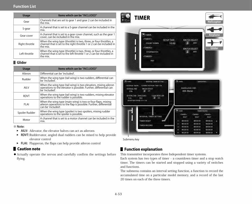
4-53
Function▋List
Usage Items▊which▊can▊be▊"INCLUDED"
Gear Channelsthataresettogear1andgear2canbeincludedinthemix.
S-gear AchannelthatissettoaS-gearchannelcanbeincludedinthemix.
Gearcover Achannelthatissettoagearcoverchannel,suchasthegear1cover,canbeincludedinthemix.
RightthrottleWhenthewingtype(throttle)istwo,three,orfourthrottles,achannelthatissettotherightthrottle1or2canbeincludedinthemix.
LeftthrottleWhenthewingtype(throttle)istwo,three,orfourthrottles,achannelthatissettotheleftthrottle1or2canbeincludedinthemix.
▋▋GliderUsage Items▊which▊can▊be▊"INCLUDED"Aileron Differentialcanbe'included'.
Rudder Whenthewingtype(tailwing)istworudders,differentialcanbe'included'.
AILVWhenthewingtype(tailwing)istwoelevators,mixingaileronoperationstotheelevatorispossible.Further,differentialcanbe'included'.
RDVT Whenthewingtype(tailwing)istworudders,mixingelevatoroperationstotherudderispossible.
FLAIWhenthewingtype(mainwing)istwoorfourflaps,mixingaileronoperationstotheflapispossible.Further,differentialcanbe'included'.
SpoilerRudder Whenthewingtype(spoiler)istwospoilers,mixingrudderoperationstothespoilerispossible.
Motor Achannelthatissettoamotorchannelcanbeincludedinthemix.
※ Note:�� AILV: Ailevator, the elevator halves can act as ailerons�� RDVT: Ruddervator, angled dual rudders can be mixed to help provide
elevator control�� FLAI: Flapperon, the flaps can help provide aileron control
▋▋Caution▋note Actually operate the servos and carefully confirm the settings before flying.
TIMER
▋▋Function▋explanationThis transmitter incorporates three Independent timer systems.Each system has two types of timer – a countdown timer and a stop watch timer. The timers can be started and stopped using a variety of switches and functions.The submenu contains an interval setting function, a function to record the accumulated time on a particular model memory, and a record of the last 20 times on each of the three timers.
Submenu key
Glider
Helicopter
Airplane
28X_EN.indd 53 2015/02/27 13:42
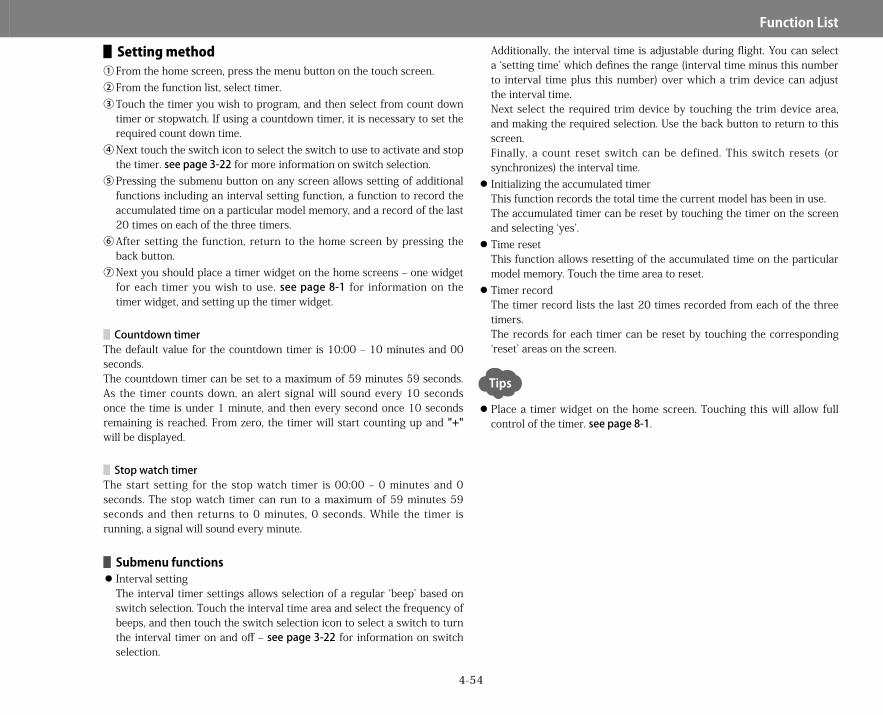
4-54
Function▋List
▋▋Setting▋method①From the home screen, press the menu button on the touch screen.②From the function list, select timer.③Touch the timer you wish to program, and then select from count down
timer or stopwatch. If using a countdown timer, it is necessary to set the required count down time.
④Next touch the switch icon to select the switch to use to activate and stop the timer. seepage3-22 for more information on switch selection.
⑤Pressing the submenu button on any screen allows setting of additional functions including an interval setting function, a function to record the accumulated time on a particular model memory, and a record of the last 20 times on each of the three timers.
⑥After setting the function, return to the home screen by pressing the back button.
⑦Next you should place a timer widget on the home screens – one widget for each timer you wish to use. seepage8-1 for information on the timer widget, and setting up the timer widget.
▋CountdowntimerThe default value for the countdown timer is 10:00 – 10 minutes and 00 seconds.The countdown timer can be set to a maximum of 59 minutes 59 seconds. As the timer counts down, an alert signal will sound every 10 seconds once the time is under 1 minute, and then every second once 10 seconds remaining is reached. From zero, the timer will start counting up and "+" will be displayed.
▋StopwatchtimerThe start setting for the stop watch timer is 00:00 – 0 minutes and 0 seconds. The stop watch timer can run to a maximum of 59 minutes 59 seconds and then returns to 0 minutes, 0 seconds. While the timer is running, a signal will sound every minute.
▋▋Submenu▋functions Interval settingThe interval timer settings allows selection of a regular ‘beep’ based on switch selection. Touch the interval time area and select the frequency of beeps, and then touch the switch selection icon to select a switch to turn the interval timer on and off – seepage3-22 for information on switch selection.
Additionally, the interval time is adjustable during flight. You can select a ‘setting time’ which defines the range (interval time minus this number to interval time plus this number) over which a trim device can adjust the interval time.Next select the required trim device by touching the trim device area, and making the required selection. Use the back button to return to this screen.Finally, a count reset switch can be defined. This switch resets (or synchronizes) the interval time. Initializing the accumulated timerThis function records the total time the current model has been in use.The accumulated timer can be reset by touching the timer on the screen and selecting ‘yes’. Time resetThis function allows resetting of the accumulated time on the particular model memory. Touch the time area to reset. Timer recordThe timer record lists the last 20 times recorded from each of the three timers.The records for each timer can be reset by touching the corresponding ‘reset’ areas on the screen.
Place a timer widget on the home screen. Touching this will allow full control of the timer. seepage8-1.
Tips
28X_EN.indd 54 2015/02/27 13:42

4-55
Function▋List
MONITOR
▋▋Function▋explanationThis function gives a graphical representation of all functions as they will work on the model. Because this shows the ‘final output’ of all servo signals, provisional confirmation of correct programming can be carried out before actually connecting the servos.This is useful for discovering unintentional mixing and switch setting mistakes. The submenu contains information on each individual channel (channel detail) and a servo test function.
▋▋Setting▋method①From the home screen, press the menu button on the
touch screen.②From the function list, select monitor.③Here you can see final servo outputs as they will be sent
to the model.④Touching an individual servo display will bring up a list of
all inputs driving that servo (channel detail).This is very handy for determining where inputs to a particular servo are being derived from. This function is also accessible from the sub menu – please see the description below.
⑤After viewing this function, return to the previous screen by pressing the back button.
⑥Pressing the submenu button allows setting of additional functions including an individual servo monitor and servo check function.
⑦Return to the home screen by pressing the home button.▋▋Submenu▋functions Channel detailThis brings up the same screen as is obtained by touching an individual servo channel. This lists all inputs driving each servo.This is very handy for determining where inputs to a particular servo are being derived from.Change servos by touching the servo name and selecting from the list. Servo testA Servo Test can be carried out within this function. Select the required servo test mode from the four options. Note that if a limit adjust has been set (seepage4-5), servos will not move further than is allowed by the limit setting. In this way you can avoid damaging servos or linkages on the aircraft if servo travel is set below 100%.Thefourtestmodesare
��Neutral:All the servos move to their neutral positions.��Slow:All servos simultaneously move at slow speed linearly using ± 100% travel.��Quick:All servos simultaneously move at high speed linearly using ± 100% travel.��Step:Each channel’s servo sequentially moves in turn using 100% travel.
Simply touch the start button to begin the test, and stop to finish.
Submenu key
Output signals of transmitter
When you touch any channel in the list, the screen will change to individual channel display. Return to the list by pressing the back button.
Mixed elements having effects on the channel
Glider
Helicopter
Airplane
28X_EN.indd 55 2015/02/27 13:42

5-1
System▋List
MODEL SELECT
▋▋Function▋explanationHere it is possible to start setting up a new model, and switch between existing models. The model select function also lets you name models, add a picture to your model, copy models to and from a SD card or USB stick, and also delete models. Up to 100 unique models can be stored in this transmitter.
▋▋Setting▋method①From the home screen, press the menu button on the touch screen.②From the system list, choose model select.
③The transmitter will cease RF transmission while in this menu. This must be confirmed on the following screen by touching on ‘yes’. Note that any active model should be first turned off.
▋Creatinganewmodel①To create a new model, touch the ‘new’ area of the screen.②It will be necessary to confirm new model creating by
touching ‘yes’.③Next it will be necessary to choose the type of model. This transmitter
supports specific functionality for airplanes, helicopters and gliders. The type selection screen is automatically displayed when creating a new model. Simply touch on the model type required.
④After the model is created, you will be returned to the model select screen. Here you will notice that the new model is automatically selected, as indicated by the red square around its model number.(picture missing the model name area)
⑤Next we should name this model.
▋Naminganewmodel(orchangingthenameofanexistingmodel)①The name of a model can only be changed if it is the currently selected
model. The currently selected model is identified by the red square around its model number. If the model you wish to name (or change the name of) is not currently selected, first refer to ‘model select’ below.
②Touch on the area of the screen indicated. This is where the model name will appear.(picture missing the model name area)
③A touch key board will appear. Enter or edit your desired model name. Remember to keep the name easy to remember which model it is referring to. Touch done when finished.▋Modelselect
①To select an existing model, touch on the model name, and then touch on ‘select’.
②It will be necessary to confirm the change of model by touching ‘yes’.③After selecting a new model, return to the home screen by pressing the
back button.
▋Modelcopy①Touch on the model you wish to copy②Touch on the copy button.
Submenu key
Glider
Helicopter
Airplane
28X_EN.indd 1 2015/02/27 13:42

5-2
System▋List
③Next select where you would like to copy the model to. Options will be internal memory, SD card (if mounted) and USB device (if connected).
④If copying to internal memory, the model will be copied to the next free model location. If copying to SD card or USB device, the model will be copied to the JR/MODEL/ folder, and the file name will include the memory location the model is being copied from and the name of the model. The file extension will be .JRM.
⑤If the file name already exists, you will be asked if you would like to change the file name. Touching ‘yes’ will allow you to do this. Touching ‘no’ will cancel the copy. You cannot overwrite an existing file name.
▋Modelload①This function is only available when you first enter the model select
menu.②Touch on load, and you will be able to load a model from SD card or USB
device if connected. The transmitter will initially look in the /JR/MODEL folder if present, but you can navigate to the folder of your choosing.
③Touch on the model you wish to load, and then touch on done.④The model will be loaded to the first free memory location on the
transmitter.
▋Modeldelete①To delete a model from the transmitter memory, first touch on the model
to be deleted on the model list. Note that the currently selected model cannot be deleted.
②You will be asked to confirm you wish to delete the model. Touch yes.Once you are finished using this function, return to the home screen by pressing the back button.
▋▋Submenu▋functions SortThis function allows the transmitter internal model memories to be sorted by model number, model name, date & time created or date and time updated.Simply touch on the option you wish to use, and the model list will be appropriately sorted. Display selectTouching display select toggles between two display options in the model select menu.
Name models in such a way so they are easily recognizable. It is possible to add an image of the model to help identify it.
▋AddingamodelimagetothemodelmenuYou will need image files on a SD card in the folder /pictures/. The images should be .jpg’s, you will be able to crop them during image selection.①First select the model you wish to change the image for.②Next touch on the image placeholder for the model.③Confirm you wish to add an image by touching yes.④Any images in the pictures folder of the SD card will be displayed.⑤Select an image. Now you will be able to crop the image as required.
Select the area of the image to use, then touch ‘crop’.⑥The image will now been shown alongside the model information.
▋▋Caution▋noteActually operate the servos and carefully confirm the correct model is selected before flying.
Never remove the SD card without either un-mounting it or turning the transmitter off. Doing this may destroy model data on the card. See page2-2 for details.
Tips
28X_EN.indd 2 2015/02/27 13:42
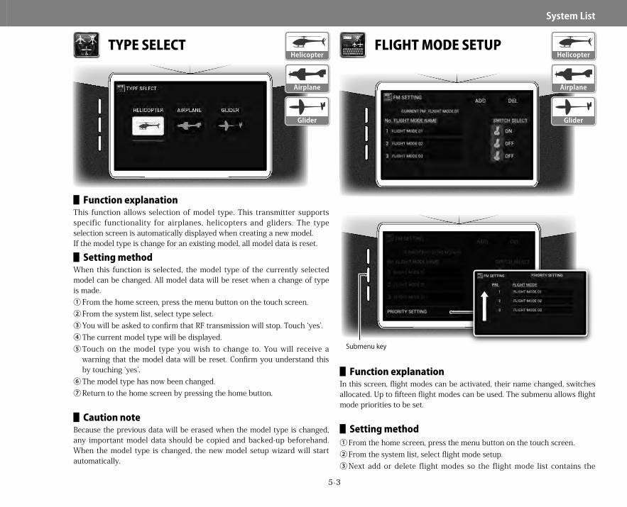
5-3
System▋List
TYPE SELECT
▋▋Function▋explanationThis function allows selection of model type. This transmitter supports specific functionality for airplanes, helicopters and gliders. The type selection screen is automatically displayed when creating a new model.If the model type is change for an existing model, all model data is reset.
▋▋Setting▋methodWhen this function is selected, the model type of the currently selected model can be changed. All model data will be reset when a change of type is made.①From the home screen, press the menu button on the touch screen.②From the system list, select type select.③You will be asked to confirm that RF transmission will stop. Touch ‘yes’.④The current model type will be displayed.⑤Touch on the model type you wish to change to. You will receive a
warning that the model data will be reset. Confirm you understand this by touching ‘yes’.
⑥The model type has now been changed.⑦Return to the home screen by pressing the home button.
▋▋Caution▋noteBecause the previous data will be erased when the model type is changed, any important model data should be copied and backed-up beforehand. When the model type is changed, the new model setup wizard will start automatically.
FLIGHT MODE SETUP
▋▋Function▋explanationIn this screen, flight modes can be activated, their name changed, switches allocated. Up to fifteen flight modes can be used. The submenu allows flight mode priorities to be set.
▋▋Setting▋method①From the home screen, press the menu button on the touch screen.②From the system list, select flight mode setup.③Next add or delete flight modes so the flight mode list contains the
Glider
Helicopter
Airplane
Submenu key
Airplane
Glider
Helicopter
28X_EN.indd 3 2015/02/27 13:42

5-4
System▋List
number of flight modes you wish to use. Do this by touching the add or delete areas on the screen.
④For each flight mode, first touch the flight mode name – this will bring up the name change dialogue where you can modify the flight mode name as required. Press the back button to return to the previous screen.
⑤On helicopter models, you can also choose the flight mode type – normal, stunt, or hold. Normally you would set up one flight mode as ‘normal, one as ‘hold’, and one or more flight modes defined as ‘stunt’.If a flight mode is defined as ‘normal’, throttle cut and throttle trim offset functions are available.If a flight mode is defined as ‘hold’, activation of this flight mode will activate the throttle hold function (page4-13).
⑥Finally select the switch to activate each flight mode. Switch selection follows the usual procedure as described on page3-22.
⑦Pressing the submenu button allows setting of additional functions including setting flight mode priorities.
⑧After setting the function, return to the home screen by pressing the back button.▋▋Submenu▋functions Priority settingsIn this function, each flight mode can be given a different priority setting. For example, if two flight modes are activated at the same time, it is important the transmitter knows which flight mode should be used. Simply touch each flight mode as required to move it up the priority list, one step at a time.
The flight mode name is displayed on the home screen flight mode widget as well as each function showing flight mode condition.▋▋Default▋flight▋modes▋are▋as▋follows▋Helicopter
1)NORMAL ・・・・・・ K SW POS02)STUNT-1 ・・・・・・ K SW POS13)STUNT-2 ・・・・・・ K SW POS2HOLD (throttle hold) is not set. If necessary, set HOLD with a name and switch position.
▋Airplane1)FLIGHT MODE 01 ・・ F SW POS02)FLIGHT MODE 02 ・・ F SW POS1
3)FLIGHT MODE 03 ・・ F SW POS2▋Glider
1)LAUNCH ・・・・・・ C SW POS12)SPEED ・・・・・・・ K SW POS03)THERMAL ・・・・・・ K SW POS24)CRUISE ・・・・・・・ K SW POS1If necessary, set LAND, ZOOM, DISTANCE, etc. with names and switch positions.
Tips
28X_EN.indd 4 2015/02/27 13:42

5-5
System▋List
FLIGHT MODE DELAY
▋▋Function▋explanationWhen the flight mode is changed, the servos may move suddenly, causing a jerky reaction in flight. To prevent this, it is possible to set a delay during which the servos will move slowly to the new position when switching flight modes. Up to 20 delays can be set. If a particular servo is being moved by a control at the time of flight mode change, the delay is ignored, and the servo immediately moves to the new position.▋▋Setting▋method
①From the home screen, press the menu button on the touch screen.②From the system list, select flight mode delay.③Here you can program delays for up to 20 different flight mode
transitions. Select the flight mode you are changing from, and the flight mode you are changing to, and then enter a delay value (0-10 seconds).Do this for each flight mode change you would like a delay set for.
④It is also possible to set a common delay, which is applied over all the flight mode changes, regardless of the flight modes being entered on this list. Touch the common delay setting, and enter a delay between 0-10 seconds.
⑤After setting the function, return to the home screen by pressing the back button.▋▋Sub▋menu▋functions▋Channelsettings
By default, flight mode delay acts upon all channels, but you may not need a delay on all channels.Deselect any channels that do not need a delay.▋▋Caution▋note
Actually operate the servos and carefully confirm the settings before flying.
TRIM SYSTEM
▋▋Function▋explanationVarious settings relating to the trims can be changed. The resolution of each trim and the trim type can be set for each flight mode. Using this function, you can easily change the trim settings. The submenu allows the trim for each function to be independent on each flight mode, or grouped to two or more flight modes – using the flight mode group settings
▋▋Setting▋method①From the home screen, press the menu button on the touch screen.②From the system list, select trim system.③First touch on the channel select area to select the channel you wish to
Helicopter
Airplane
Glider
Submenu key
Trim
Glider
Helicopter
Airplane
28X_EN.indd 5 2015/02/27 13:42

5-6
System▋List
change the trim setup for.④Next choose the trim input device. Touch the trim input device area, and
select the trim device from the graphic. Selecting ‘INH’ inhibits the trim function.
⑤Now set the trim step. This determines how much trim you get with each click of trim. This can be set between 0-200. Not that if you set the step to 0, the trim will be inactive. With the trim set to 200, full trim deflection occurs with one click. Note the trim step does not change the total trim throw – only how many clicks it takes to get to full trim deflection.
⑥The trim can also be reversed. Touch the reverse box, and select on or off.
⑦The trim type can also be selected – either normal or LST.a.Normal trim (norm): Results in the trim lever having an effect over the
entire servo operation range.b.Limit stroke trim (LST): The trim has its greatest effect when the
control function is at neutral, and the effect of the trim will disappear at the stick end positions. End point travel adjustment is not changed by the trim settings. It is possible to avoid damage to servos, linkages and control surfaces by using LST.
c. The throttle function automatically uses a special form of LST. This trim only functions at the low position of the throttle stick, and by half throttle the trim has no effect.
⑧A switch can also be selected to turn the trim on and off. With the trim off, current trim settings are maintained. See page3-22 for information about switch selection.
⑨Some functions include a ‘use’ menu, trim rate, input type and offset.⑩Pressing the submenu button allows setting of trim flight mode groups.⑪After setting the function, return to the home screen by pressing the
back button.
▋▋Submenu▋functions Flight mode group settingsIn this function, the trims associated with each function can be set individually for each flight mode (separate trim), or grouped together and set for two or more flight modes (common trim).After selecting this function, first select the trim function you wish to program – touch the function area of the screen and select the trim.Now select the trim group for each flight mode. Up to 15 individual trim groups can be used. If the trim is set to a different group for each flight mode, the trims are
all set individually in each flight mode. If all flight modes are set to the same group, altering the trim in one flight mode will also change the trim in another. This function is set individually for each trim function.
By setting the trim step to "0" it is possible to inhibit the operation of a trim lever.
Tips
28X_EN.indd 6 2015/02/27 13:42

5-7
System▋List
ANALOGUE POSITION SWITCH
▋▋Function▋explanationThis function allows switching (on/off ) of virtual switches using stick operation. Virtual switches can be programmed to any stick position, and then used to switch various functions on and off.
▋▋Setting▋methodTen analogue position switches (APS) are available (APS0-APS9). All the switches are initially inhibited.①From the home screen, press the menu button on the touch screen.②From the system list, select analogue position switch.③There are ten definable APS’s. Simply touch the arrows to change
screens.④Activate an APS by touching ‘INH’ and selecting ‘ACT’.⑤Next choose an input device for the switch. Touch the input device box,
and select the input as either a device or channel.a.Device: The input is taken from raw values from a control, irrespective
of any mixes, etc that may be effecting the function.b.Channel: Selecting a channel means the final channel output is used
for the APS. This would include any trim settings, mixes, etc.⑥Now set the switch logic. The switch can be set with three possible on/
off configurations, and four user defined switching zones.There is an on/off indication on the screen which is of great help when programming the APS logic. Start by deciding in which basic areas you wish the APS to be on or off. Three zones can be set as shown below.
After setting these zones, it is now necessary to set the switch logic within each zone. I will use an example of an APS setup as on-off-on.
The first position box sets the point the APS will change from on to off, as the stick is moved from the extreme of travel toward center. This is shown by the grey bar.Next set the point at which the APS will change from off to on, when the stick is moved from the center position back to the left position on the image. The point of switching is indicated by the blue bar.The remaining two switch points are set in a similar manner.
※ Note that at least one switch point must be set for the APS to function.As you experiment with different set points, you will discover how powerful this function is.
⑦After setting the function, return to the home screen by pressing the back button.
In various functions, by choosing analogue position switch, it is possible to turn functions on and off using stick control. The function display shows the current APS switch position (on/off ) - this is very useful when setting up this function.
▋▋Caution▋noteActually operate the servos and carefully confirm the settings before flying.
Glider
Helicopter
Airplane
Tips
28X_EN.indd 7 2015/02/27 13:42
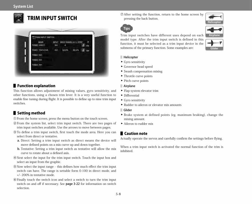
5-8
System▋List
TRIM INPUT SWITCH
▋▋Function▋explanationThis function allows adjustment of mixing values, gyro sensitivity, and other functions, using a chosen trim lever. It is a very useful function to enable fine tuning during flight. It is possible to define up to nine trim input switches.
▋▋Setting▋method①From the home screen, press the menu button on the touch screen.②From the system list, select trim input switch. There are two pages of
trim input switches available. Use the arrows to move between pages.③To define a trim input switch, first touch the mode area. Here you can
select from direct or tentative.a.Direct: Setting a trim input switch as direct means the device will
move defined points on a mix curve up and down together.b.Tentative: Setting a trim input switch as tentative will allow the mix
curve to rotate about a defined axis.④Next select the input for the trim input switch. Touch the input box and
select an input from the graphic.⑤Now select the input range – this defines how much effect the trim input
switch can have. The range is settable form 0-100 in direct mode, and +/- 200% in tentative mode.
⑥Finally touch the switch icon and select a switch to turn the trim input switch on and off if necessary. See page3-22 for information on switch selection.
⑦After setting the function, return to the home screen by pressing the back button.
Trim input switches have different uses depend on each model type. After the trim input switch is defined in this function, it must be selected as a trim input device in the submenu of the primary function. Some examples are:
▋Helicopter �Gyro sensitivity �Governor head speed � Swash compensation mixing �Throttle curve points �Pitch curve points▋Airplane � Flap system elevator trim �Differential �Gyro sensitivity �Rudder to aileron or elevator mix amounts▋Glider �Brake system at defined points (eg. maximum braking), change the mixing amount. �Aileron to rudder mix
▋▋Caution▋noteActually operate the servos and carefully confirm the settings before flying.
When a trim input switch is activated the normal function of the trim is inhibited.
Glider
Helicopter
Airplane
Tips
28X_EN.indd 8 2015/02/27 13:42
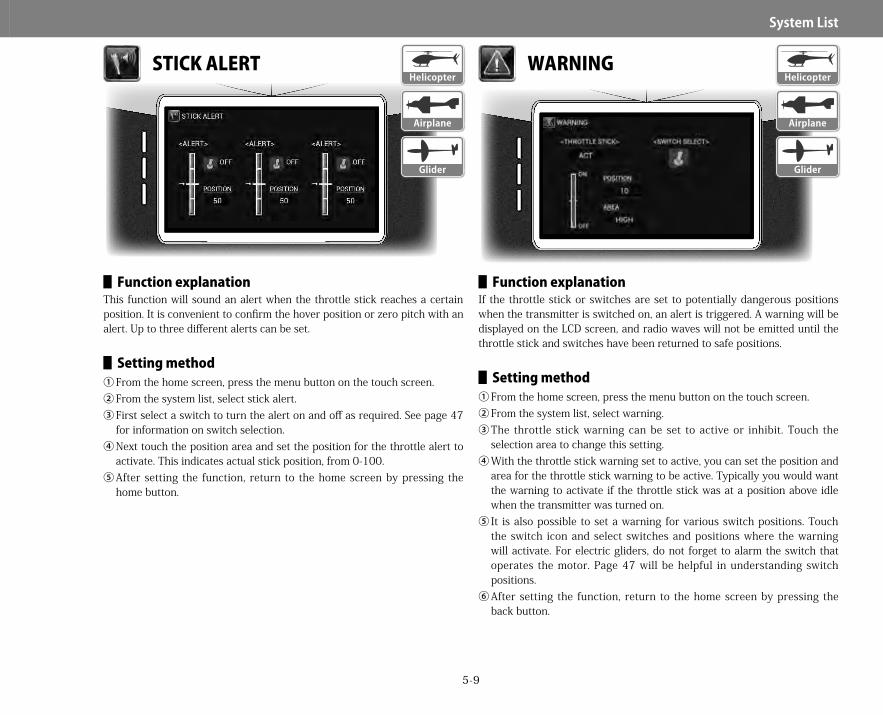
5-9
System▋List
STICK ALERT
▋▋Function▋explanationThis function will sound an alert when the throttle stick reaches a certain position. It is convenient to confirm the hover position or zero pitch with an alert. Up to three different alerts can be set.
▋▋Setting▋method①From the home screen, press the menu button on the touch screen.②From the system list, select stick alert.③First select a switch to turn the alert on and off as required. See page 47
for information on switch selection.④Next touch the position area and set the position for the throttle alert to
activate. This indicates actual stick position, from 0-100.⑤After setting the function, return to the home screen by pressing the
home button.
WARNING
▋▋Function▋explanationIf the throttle stick or switches are set to potentially dangerous positions when the transmitter is switched on, an alert is triggered. A warning will be displayed on the LCD screen, and radio waves will not be emitted until the throttle stick and switches have been returned to safe positions.
▋▋Setting▋method①From the home screen, press the menu button on the touch screen.②From the system list, select warning.③The throttle stick warning can be set to active or inhibit. Touch the
selection area to change this setting.④With the throttle stick warning set to active, you can set the position and
area for the throttle stick warning to be active. Typically you would want the warning to activate if the throttle stick was at a position above idle when the transmitter was turned on.
⑤It is also possible to set a warning for various switch positions. Touch the switch icon and select switches and positions where the warning will activate. For electric gliders, do not forget to alarm the switch that operates the motor. Page 47 will be helpful in understanding switch positions.
⑥After setting the function, return to the home screen by pressing the back button.
Helicopter
Glider
Airplane
Glider
Helicopter
Airplane
28X_EN.indd 9 2015/02/27 13:42

5-10
System▋List
▋Warningdefaults HelicopterInitially, the warning alert will not shut off unless the following conditions are met:Throttle stick set to the lowest position.Flight mode switch set to normal mode. AirplaneInitially, the warning alert will not shut off unless the following conditions are met:Throttle stick set to the lowest position. GliderThere is no warning alert default for glider mode. If necessary, set a warning which suits your application. For example, with an electric power glider, you may set a warning to ensure the motor switch is in the off position when the transmitter is turned on.
▋▋Caution▋noteFor safety reasons, be certain to activate this function and check the warning works as expected.
TRANSMITTER SETTING
▋▋Function▋explanationThis function allows basic adjustment of transmitter settings such as battery mode, idle alert, alarm volumes, etc. The submenu allows calibration of the transmitter sticks.
▋▋Setting▋method①From the home screen, press the menu button on the touch screen.②From the system list, select transmitter setting. There are three screens
of information accessible using the arrow keys.
Submenu key
Glider
Helicopter
Airplane
28X_EN.indd 10 2015/02/27 13:42

5-11
System▋List
③Battery logic:a. It is possible to change how the two transmitter batteries are used.
Battery A may be used first, or battery B, or both used simultaneously.b.Touch the battery area, and select from the menu.c. The battery alarm voltages can be set by touching the alarm voltage
area and setting a new alarm voltage.④Idle alert:
a. It is possible to change the transmitter idle time (latency) before the idle alert sounds. This can be set between 0 (inhibit) and 254 minutes.
⑤System sounds can be adjusted.The tone and volume can be changed. Simply touch the area to modify.The last screen in this function shows the current transmitter firmware version.Pressing the submenu button allows calibration of the transmitter sticks.After setting the function, return to the home screen by pressing the home button.
⑥LED brightnessControls the brightness of the power switch LED. Select from high (default) or low.▋▋Submenu▋functions Stick calibrationThis function calibrates the neutral position of the sticks, and stick travel which is especially useful after changing stick modes (mode 1 to mode 2, etc) and after any changes to stick travel. After entering this function, the calibration procedure is as follows.
①Set both right and left sticks to their center positions, and press the set key to calibrate neutral.
②Next move both right and left sticks up and down and right to left and then press the set key to calibrate stick travel.
③Be sure to check control movement and neutral positions on the servo monitor screen.
TRAINER SYSTEM
▋▋Function▋explanationThis function allows two transmitters to be connected via a trainer cable (sold separately) to allow dual control flight instruction. A skilled pilot can teach a beginner how to fly an aircraft using this trainer system. The 28X can function as the master (trainer) or pupil (trainee). Control can be changed between master and pupil using the master transmitter’s trainer switch (user defined).
▋▋Setting▋method①From the home screen, press the menu button on the touch screen.②From the system list, select trainer system.③The trainer type can be set to normal or program – touch the type
Normal
Program
Select Normal/Program
Glider
Helicopter
Airplane
28X_EN.indd 11 2015/02/27 13:42

5-12
System▋List
selection area and select the desired mode.④The switch to allow the master transmitter to give control to the pupil
transmitter (‘trainer switch’) can be freely selected. Touch the switch icon, and select a switch. See page3-22 for information on switch selection.
⑤After setting the function, return to the home screen by pressing the back button.▋▋As▋a▋master▋transmitter
When using the 28X as the master:①The main power must be turned on - the transmitter is transmitting radio
waves - and is bound to the aircraft.②The trainer cable is plugged in.
The ‘trainer switch’ is selected in the master transmitter as above. There are two modes available for the master transmitter.In normal mode the pupil transmitter can be another JR 28X, JR XG 6, 8, 11, 14 or JR 11X. Some Spektrum transmitters are also compatible. The pupil transmitter should always have its power switch in the off position. In program mode, the pupil transmitter must be a compatible JR transmitter which includes program mode as a ‘slave’. Examples include the JR 28X, JR XG 6, 8, 11, 14 or JR 11X.▋▋Normal▋mode
The master transmitter normally controls the model. Control data comingfrom pupil transmitter is only sent to the aircraft by switching control frommaster to pupil using the defined trainer switch. Both master and pupil transmitter must have the same program settings, including servo reverse, trim and dual rate settings, etc. Data from the pupil transmitter is sent directly to the model. The pupil transmitter should be in PPM mode (not slave mode).Always carefully check all control functions of the master and pupil transmitters. If any pupil control inputs are moving the wrong functions, this can be corrected in the below screen. Simply change the channel controlling the particular function.Additionally, this screen can be used to define pupil transmitter controls to different functions on the aircraft. For example, it is possible to have a master transmitter control the primary functions, and have a pupil transmitter control say a camera gimbal on a multirotor model.▋▋Program▋trainer
The master transmitter must be programmed and bound to the model. The pupil transmitter does not need to be programed to match the model. Flight mode, dual rate and trim settings are all controlled by the master transmitter.
Both transmitter must be set to program mode.If the 28X is the master, simply select from the left hand list which stick inputs from the pupil transmitter should control which functions on the aircraft. Select one or more channels to be controlled by the pupil transmitter. This allows the beginner pilot to learn a single control at a time. This is makes it easier to learn, without the worry of controlling all functions at once. The data coming from pupil to master is combined with data from the master transmitter settings (trim, dual rates, mixing, etc…) before being transmitted to the model. Precise adjustments and settings must be done on the master transmitter. The pupil transmitter must be selected as a pupil (slave) in the pupil transmitter programming. This trainer program is available on most recent JR computer transmitters.▋▋As▋a▋pupil▋transmitter
When using the 28X as a pupil transmitter:①The main power switch must always remain off.②The trainer cable is plugged in.There are two modes available for the pupil transmitter:
�Normal mode:When the master transmitter is set to normal mode, the pupil transmitter should also be set to normal mode. There are no specific setting requirements, however, if the radio has a trainer program, do not set it to pupil. �Program mode:Use this mode when the master transmitter is set to "programtrainer". When set as a pupil, only the gimbal stick functions pass control outputs to the master transmitter. Therefore, settings such as dual rates and mixing are ignored completely.
The master transmitter can be another JR 28X, JR XG 6, 8, 11, 14 or JR 11X. Some Spektrum transmitters are also compatible. The master transmitter should always have its power switch in the on position, and be bound to the model.
▋▋Caution▋noteBe sure to check both master and slave transmitters for correct function and control prior to commencing flight training using two transmitters. Pay particular attention to control direction, dual rates, trim settings, mixing, etc.
28X_EN.indd 12 2015/02/27 13:42
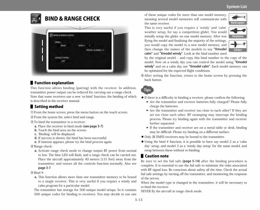
5-13
System▋List
BIND & RANGE CHECK
▋▋Function▋explanationThis function allows binding (pairing) with the receiver. In addition, transmitter power output can be reduced for carrying out a range check.Note that some receivers use a new 'ez-bind' function, the binding of which is described in the receiver manual.
▋▋Setting▋method①From the home screen, press the menu button on the touch screen.②From the system list, select bind and range.③To bind the transmitter to a receiver:
a.Place the receiver in bind mode (seepage3-7)b.Touch the bind area on the screen.c. ‘Binding’ will be displayed.d.If success is shown, the bind has been successful.e. If timeout appears, please try the bind process again.
④Range check:a.Activate range check mode to change output RF power from normal
to low. The blue LED will flash, and a range check can be carried out. Place the aircraft approximately 40 meters (131 feet) away from the transmitter, and ensure all the controls function normally. Also see page3-7.
⑤Bind #:a.This function allows more than one transmitter memory to be bound
to a single receiver. This is very useful if you require a windy and calm program for a particular model.
The transmitter has storage for 500 unique model setups. So it contains 500 unique codes for binding to receivers. You may decide to use one
of these unique codes for more than one model memory, meaning several model memories will communicate with the same receiver.This is very useful if you require a ‘windy’ and ‘calm’ weather setup, for say a competition glider. You would initially setup the glider on one model memory. After test flying the model and finalizing the majority of the settings, you would copy the model to a new model memory, and then change the names of the models to say "Xmodelcalm" and "Xmodelwindy". Look at the bind number used by the original model – and copy this bind number to the copy of the model. Now on a windy day you can control the model using "Xmodelwindy" and on a calm day use "Xmodelcalm". Each model memory can be optimized for the expected flight conditions.
⑥After setting the function, return to the home screen by pressing the back button.
If there is a difficulty in binding a receiver, please confirm the following:��Are the transmitter and receiver batteries fully charged? Please fully charge the batteries.��Are the transmitter and receiver too close to each other? If they are set too close each other, RF swamping may interrupt the binding process. Please try binding again with the transmitter and receiver further separated.��If the transmitter and receiver are on a metal table or desk, binding may be difficult. Please try binding on a different surface.
Only JR DMSS receivers may be bound to the transmitter. Using the bind # function, it is possible to have say model 2 as a ‘calm day’ setup, and model 3 as a ‘windy day setup’ for the same model, and swap between these without re-binding.
▋▋Caution▋noteBe sure to set the fail safe (page5-14) after the binding procedure is complete. It is essential to use the fail safe to minimize the risks associated with RF signal loss. Be conscious about safety all the time. Check the actual fail safe settings by turning off the transmitter, and monitoring the response of the servos.When the model type is changed in the transmitter, it will be necessary to re-bind the receiver.NEVER fly the aircraft in range check mode.
Glider
Helicopter
Airplane
Tips
28X_EN.indd 13 2015/02/27 13:42
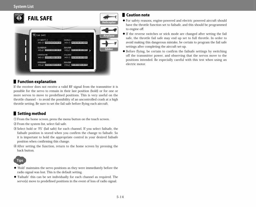
5-14
System▋List
FAIL SAFE
▋▋Function▋explanationIf the receiver does not receive a valid RF signal from the transmitter it is possible for the servo to remain in their last position (hold) or for one or more servos to move to predefined positions. This is very useful on the throttle channel – to avoid the possibility of an uncontrolled crash at a high throttle setting. Be sure to set the fail safe before flying each aircraft.
▋▋Setting▋method①From the home screen, press the menu button on the touch screen.②From the system list, select fail safe.③Select hold or ‘FS’ (fail safe) for each channel. If you select failsafe, the
failsafe position is stored when you confirm the change to failsafe. So it is important to hold the appropriate control in your desired failsafe position when confirming this change.
④After setting the function, return to the home screen by pressing the back button.
‘Hold’ maintains the servo positions as they were immediately before the radio signal was lost. This is the default setting. ‘Failsafe’ this can be set individually for each channel as required. The servo(s) move to predefined positions in the event of loss of radio signal.
▋▋Caution▋note For safety reasons, engine-powered and electric powered aircraft should have the throttle function set to failsafe, and this should be programmed to engine off. If the reverse switches or stick mode are changed after setting the fail safe, the throttle fail safe may end up set to full throttle. In order to avoid making this dangerous mistake, be certain to program the fail safe settings after completing the aircraft set-up. Before flying, be certain to confirm the failsafe settings by switching off the transmitter power, and observing that the servos move to the positions intended. Be especially careful with this test when using an electric motor.
Glider
Helicopter
Airplane
Tips
28X_EN.indd 14 2015/02/27 13:42
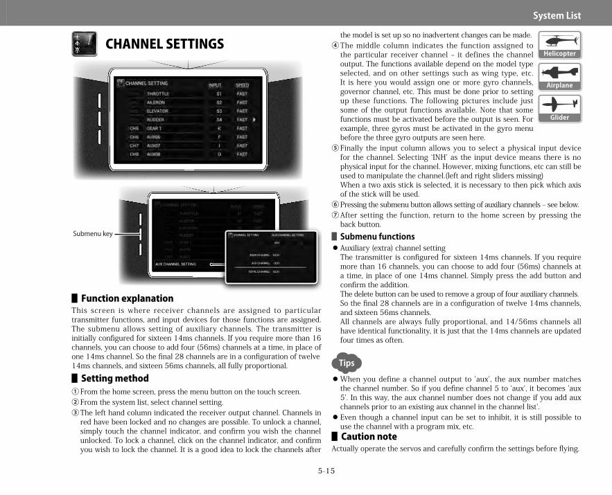
5-15
System▋List
CHANNEL SETTINGS
▋▋Function▋explanationThis screen is where receiver channels are assigned to particular transmitter functions, and input devices for those functions are assigned. The submenu allows setting of auxiliary channels. The transmitter is initially configured for sixteen 14ms channels. If you require more than 16 channels, you can choose to add four (56ms) channels at a time, in place of one 14ms channel. So the final 28 channels are in a configuration of twelve14ms channels, and sixteen 56ms channels, all fully proportional.▋▋Setting▋method
①From the home screen, press the menu button on the touch screen.②From the system list, select channel setting.③The left hand column indicated the receiver output channel. Channels in
red have been locked and no changes are possible. To unlock a channel, simply touch the channel indicator, and confirm you wish the channel unlocked. To lock a channel, click on the channel indicator, and confirm you wish to lock the channel. It is a good idea to lock the channels after
the model is set up so no inadvertent changes can be made.④The middle column indicates the function assigned to
the particular receiver channel – it defines the channel output. The functions available depend on the model type selected, and on other settings such as wing type, etc. It is here you would assign one or more gyro channels, governor channel, etc. This must be done prior to setting up these functions. The following pictures include just some of the output functions available. Note that some functions must be activated before the output is seen. For example, three gyros must be activated in the gyro menu before the three gyro outputs are seen here.
⑤Finally the input column allows you to select a physical input device for the channel. Selecting ‘INH’ as the input device means there is no physical input for the channel. However, mixing functions, etc can still be used to manipulate the channel.(left and right sliders missing)When a two axis stick is selected, it is necessary to then pick which axis of the stick will be used.
⑥Pressing the submenu button allows setting of auxiliary channels – see below.⑦After setting the function, return to the home screen by pressing the
back button.▋▋Submenu▋functions Auxiliary (extra) channel settingThe transmitter is configured for sixteen 14ms channels. If you require more than 16 channels, you can choose to add four (56ms) channels at a time, in place of one 14ms channel. Simply press the add button and confirm the addition. The delete button can be used to remove a group of four auxiliary channels.So the final 28 channels are in a configuration of twelve 14ms channels, and sixteen 56ms channels.All channels are always fully proportional, and 14/56ms channels all have identical functionality, it is just that the 14ms channels are updated four times as often.
When you define a channel output to 'aux', the aux number matches the channel number. So if you define channel 5 to 'aux', it becomes 'aux 5'. In this way, the aux channel number does not change if you add aux channels prior to an existing aux channel in the channel list'. Even though a channel input can be set to inhibit, it is still possible to use the channel with a program mix, etc.▋▋Caution▋note
Actually operate the servos and carefully confirm the settings before flying.
Submenu key
Helicopter
Glider
Airplane
Tips
28X_EN.indd 15 2015/02/27 13:42

5-16
System▋List
SWASH TYPE
▋▋Function▋explanationThis function allows electronic CCPM mixing to match the mechanical structure and control of the helicopter swash plate. After making the swash type selection, detailed settings should be made using swash mixing in the function list (page 122). The submenu allows swash angle correction (electronic swashplate phasing adjustment).
▋▋Setting▋method①From the home screen, press the menu button on the touch screen.
②From the system list, select swash type.③Touch the area of the screen representing the swashplate.④From here select the swash plate configuration which
matches your helicopter. Note the top of the screen represents the front of the helicopter. There are twelve possible swash configurations, spread over two screens. Simply touch on the configuration which matches your helicopter.
⑤Pressing the submenu button allows electronic setting of swashplate angle correction (phasing) – see below.
⑥After setting the function, return to the home screen by pressing the back button.
※ Note that the actual mixing amount and direction settings, etc are made in ‘swash mixing’, found in the function list, page4-19.
▋▋Submenu▋functions Swash angle correction (phasing)Selecting this function allows the phasing angle of the swashplate to be changed electronically. Note that this should not be done on flybarless helicopters using electronic stabilization – this should instead be done within the flybarless unit.
Many flybarless systems require the transmitter to be set to 1s normal swashplate configuration, regardless of the actual helicopter swash configuration. Please be careful of this when using a flybarless flight controller.
▋▋Caution▋noteActually operate the servos and carefully confirm the settings before flying.Submenu key
Helicopter
Tips
28X_EN.indd 16 2015/02/27 13:42

5-17
System▋List
WING TYPE
▋▋Function▋explanationHere the wing type can be set. Dual ailerons and dual flaps, dual elevators, dual rudders, tailless planes, and V-tail wings can be selected. Multiengine aircraft throttle configuration is also set here.
▋▋Setting▋method①From the home screen, press the menu button on the touch screen.②From the system list, select wing type.③Now select the layout you would like to adjust – for example, ‘main wing’
or ‘tail wing’, and then select from the options available.④After setting the function, return to the home screen by pressing the
back button.This options available with this function vary depending on which model type you have selected – glider or airplane.After selecting the various configurations, check the channels setting options (page331) and here you will be able to see (and change) the default receiver channel outputs for each control surface.
▋▋Airplane▋Mainwing
Here select the main wing configuration. It is very easy to understand the wing servo configuration by looking at the pictures of each main wing type.
One aileron – Select this option if the wing uses a single aileron servo. Flaperon – Select this option if you use two aileron servos, which can
also be used as flaps. Two ailerons – Select this option if you are using two aileron servos, and don’t wish them to be used as flaps. Two ailerons + one flap – This option is used if you are using two aileron servos, and a separate single flap servo. Two ailerons and two flaps – This option is used if you are using two aileron servos, and two flap servos. Two ailerons and four flaps – This option is used if you are using two aileron servos, and four flap servos. Four ailerons – This option is used if your wing uses four aileron servos. Four ailerons and one flap – This option is used if you are using four aileron servos, and a separate single flap servo. Four ailerons and two flaps – This option is used if you are using four aileron servos, and two flap servos. Four ailerons and four flaps – This option is used if you are using four aileron servos, and four flap servos. Delta – This option is used when the ailerons must also act as elevators. Delta and one flap – This option is used when the ailerons must also act as elevators, and you have a single flap servo. Delta and two flaps – This option is used when the ailerons must also act as elevators, and you have two flap servos. Delta and four flaps - T his option is used when the ailerons must also act as elevators, and you have four flap servos.▋Tailtype
Here you can choose the tail configuration of your plane. One elevator and one rudder – This is the ‘standard’ configuration for most aircraft. A single servo controls the elevator, and a single servo controls the rudder. Two elevators and one rudder – Choose this option if your model uses dual elevator servos. Two elevators and two rudders - Choose this option if your model uses dual elevator servos and two rudder servos. V-tail – choose this option if your model uses a v-tail, requiring mixing of two servos for elevator and rudder control.
▋Throttle One throttle – Use this option if your airplane uses a single motor and throttle servo. Two throttles - Use this option if your airplane uses two motors.
Airplane
Glider
28X_EN.indd 17 2015/02/27 13:42
5-18
System▋List
Three throttles - Use this option if your airplane uses three motors. Four throttles - Use this option if your airplane uses four motors.
※ Note that it is possible to add normal throttle trim to this second channel, or add a separate trim lever as the second throttle trim.The throttle hold function (page4-13) is useful for bringing one or more motors back to idle and holding them there.
▋▋Glider▋Mainwing
Here select the main wing configuration. It is very easy to understand the wing servo configuration by looking at the pictures of each main wing type.
Two ailerons + one flap – This option is used if you are using two aileron servos, and a separate single flap servo. Two ailerons and two flaps – This option is used if you are using two aileron servos, and two flap servos. Two ailerons and four flaps – This option is used if you are using two aileron servos, and four flap servos. Four ailerons and one flap – This option is used if you are using four aileron servos, and a separate single flap servo. Four ailerons and two flaps – This option is used if you are using four aileron servos, and two flap servos. Four ailerons and four flaps – This option is used if you are using four aileron servos, and four flap servos.
▋TailwingHere you can choose the tail configuration of your glider.
One elevator and one rudder – This is the ‘standard’ configuration for most aircraft. A single servo controls the elevator, and a single servo controls the rudder. Two elevators and one rudder – Choose this option if your model uses dual elevator servos. Two elevators and two rudders - Choose this option if your model uses dual elevator servos and two rudder servos. V-tail – choose this option if your model uses a v-tail, requiring mixing of two servos for elevator and rudder control.▋Spoiler One spoiler – Choose this option if your glider uses a single spoiler channel. Two spoilers - Choose this option if your glider uses two spoiler channels.
▋▋Caution▋noteActually operate the servos and carefully confirm the settings before flying.
28X_EN.indd 18 2015/02/27 13:42
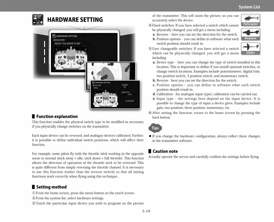
5-19
System▋List
HARDWARE SETTING
▋▋Function▋explanationThis function enables the physical switch type to be modified as necessary if you physically change switches on the transmitter.
Each input device can be reversed, and analogue devices calibrated. Further, it is possible to define individual switch positions, which will affect their function.
For example, some pilots fly with the throttle stick working in the opposite sense to normal (stick away = idle, stick down = full throttle). This function allows the direction of operation of the throttle stick to be reversed. This is quite different from simply reversing the throttle channel. It is necessary to use this function (rather than the reverse switch) so that all mixing functions work correctly when flying using this technique.
▋▋Setting▋method①From the home screen, press the menu button on the touch screen.②From the system list, select hardware settings.③Touch the particular input device you wish to program on the picture
of the transmitter. This will zoom the picture, so you can accurately select the device.
④Fixed switches: If you have selected a switch which cannot be physically changed, you will get a menu includinga.Reverse – here you can set the direction for the switch.b.Position options – you can define in software what each
switch position should result in.⑤User changeable switches: If you have selected a switch
which can be physically changed, you will get a menu includinga.Device type – here you can change the type of switch installed in this
location. This is important to define if you install optional switches, or change switch locations. Examples include potentiometer, digital trim, two position switch, 3 position switch, and momentary switch.
b.Reverse - here you can set the direction for the switch.c. Position options – you can define in software what each switch
position should result in.d.Calibration - for analogue input types, calibration can be carried out.e. Input type – the settings here depend on the input device. It is
possible to change the type of input a device gives. Examples include gain, two position, three position, momentary, etc.
⑥After setting the function, return to the home screen by pressing the back button.
If you change the hardware configuration, always reflect these changes in the transmitter software.
▋▋Caution▋noteActually operate the servos and carefully confirm the settings before flying.
Glider
Helicopter
Airplane
Tips
28X_EN.indd 19 2015/02/27 13:42

5-20
System▋List
STICK ACCELERATOR
▋▋Function▋explanationThis function enables the transmitter to accentuate the action of a particular stick movement. Two acceleration profiles are available, and switches can be set to change between these in flight. This function should be used with caution, and only be experienced pilots. If you quickly move a stick on the transmitter, this function anticipates you are requiring an immediate and large response, so sends a larger signal to the appropriate receiver channel. You can set the area of stick travel where the function is active, and set the degree of acceleration and recovery time.
▋▋Setting▋methodIt is possible to setup two accelerator profiles for two different controls (ACCEL1 and ACCEL2). A switch can be assigned to turn the accelerators on and off. Note the same switch is used to control both ACCEL1 and 2.①From the home screen, press the menu button on the touch screen.②From the system list, select stick accelerator.③Select the accelerator profile you wish to program. Touch the ACCELx
part of the screen and select the profile to program.④Next touch the switch icon, and here you can select the switch or
switches to use for turning the accelerator on and off. Select a switch or switches in the usual manner (page3-22). Use the back button to return to the previous screen.
⑤Next select the stick you wish to use the stick accelerator function for. Click on the stick selection dialogue and select the stick from the available options.
⑥Now program the area of stick travel the accelerator function will be active. Normally you would want the accelerator off in the center of stick travel (to allow small corrections normally required during flight), and have the accelerator on toward extremes of travel.The setting of on/off points is then required. These are set in the same ways as the on/off points for the analogue position switch (APS) function,so it is useful to refer to that section of the manual for information on this setting. See page5-7.Note that it is possible to set a hysteresis for turning the accelerator on and off.
⑦Now set the required scale - either low or center. Low means the accelerator works from low stick position. Center means the accelerator is based around center stick. This is the mode you would normally use.
⑧Next set the rate and recovery time in both direction of travel.The rate sets the acceleration in that direction of travel.The return sets how quickly the servo will return to match the stick position.These values are set independently for both travel away from center, and travel toward center.
⑨Now set the ACCEL parameter. This sets how long the overshoot position is held for.
⑩After setting the function, return to the home screen by pressing the back button.
This function is ideal for experienced pilots experimenting with unique maneuvers requiring the fastest response times available.
▋▋Caution▋noteActually operate the servos and carefully confirm the settings before flying.
Glider
Helicopter
Airplane
Tips
28X_EN.indd 20 2015/02/27 13:42

5-21
System▋List
ALL SERVO HOLD
▋▋Function▋explanationThis function holds (locks) all the servos in their current positions. It is used when the operator does not wish the servos to move, typically during some radio adjustments. When this function is set to on, the blue RF indicator LED on the switch will flash, indicating all servos are held.
▋▋Setting▋method①From the home screen, press the menu button on the touch screen.②From the system list, select all servo hold.③Touch the 'off' button, and then 'yes' to activate this function. The servos
will now remain held at their current positions.To de-activate the hold, touch 'on', and then select 'yes'. The servos are now active again.
④After setting the function, return to the home screen by pressing the back button.
Additionally, for helicopter models, it is possible to disable the dialogue which normally asks if you wish to hold the servos while adjusting certain functions (dual rate & expo, throttle curve, pitch curve, gyro sensitivity).
With this turned off, the hold dialogue will not appear, and the servos will not be held during adjustment. Be very careful making adjustments when the servos are not held.
The function is disabled by touching the 'on' area, and confirming you wish to turn the function off.
▋▋Caution▋noteWarning: It is very dangerous to set this function to be activate at the same time as an electric motor is being connected, as the motor may start moving and not be able to be shut off immediately. Take extra care and attention to disconnect any electric motors before activating this function.
This screen is for Helicopter type.This screen is for Helicopter type.
Helicopter
Airplane
Glider
28X_EN.indd 21 2015/02/27 13:42
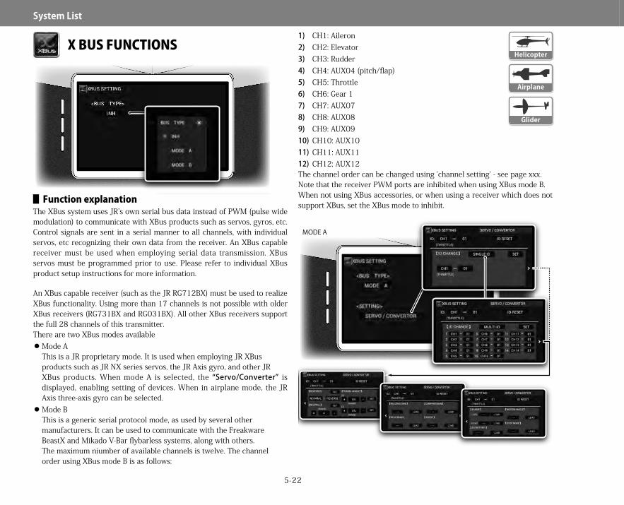
5-22
System▋List
X BUS FUNCTIONS
▋▋Function▋explanationThe XBus system uses JR’s own serial bus data instead of PWM (pulse wide modulation) to communicate with XBus products such as servos, gyros, etc. Control signals are sent in a serial manner to all channels, with individual servos, etc recognizing their own data from the receiver. An XBus capable receiver must be used when employing serial data transmission. XBus servos must be programmed prior to use. Please refer to individual XBus product setup instructions for more information.
An XBus capable receiver (such as the JR RG712BX) must be used to realizeXBus functionality. Using more than 17 channels is not possible with older XBus receivers (RG731BX and RG031BX). All other XBus receivers support the full 28 channels of this transmitter.There are two XBus modes available
Mode AThis is a JR proprietary mode. It is used when employing JR XBusproducts such as JR NX series servos, the JR Axis gyro, and other JRXBus products. When mode A is selected, the “Servo/Converter” is displayed, enabling setting of devices. When in airplane mode, the JR Axis three-axis gyro can be selected. Mode BThis is a generic serial protocol mode, as used by several othermanufacturers. It can be used to communicate with the FreakwareBeastX and Mikado V-Bar flybarless systems, along with others.The maximum niumber of available channels is twelve. The channelorder using XBus mode B is as follows:
1) CH1: Aileron2) CH2: Elevator3) CH3: Rudder4) CH4: AUX04 (pitch/flap)5) CH5: Throttle6) CH6: Gear 17) CH7: AUX078) CH8: AUX089) CH9: AUX0910) CH10: AUX1011) CH11: AUX1112) CH12: AUX12The channel order can be changed using 'channel setting' - see page xxx.Note that the receiver PWM ports are inhibited when using XBus mode B.When not using XBus accessories, or when using a receiver which does not support XBus, set the XBus mode to inhibit.MODE A
Glider
Helicopter
Airplane
MODE A
28X_EN.indd 22 2015/02/27 13:42

5-23
System▋List
▋▋Setting▋method①From the home screen, press the menu button on the touch screen.②From the system list, select XBus.③Select XBus mode A, mode B or inhibit as required.④If mode A is chosen, many other settings are available as required – see
below. Note that there will be no PWM output signals from standard ports on the receiver when XBus has been activated in mode B. When using a DMSS receiver without XBus capability the bus type should be set to inhibit.
⑤After setting the function, return to the home screen by pressing the back button.▋▋XBus▋mode▋A▋settings XBus ID’sXBus components operate on the basis of a main ID and sub ID where:
��The main ID identifies the function of that particular component e.g. aileron, elevator, rudder, throttle, and so forth. The channel name will vary depending on the wing type or swash type being used.��The sub ID number identifies 1-4 servos moving in unison on the particular function. XBus allows up to four components per function, meaning that each channel can control up to four servos. It is possible to fine tune the neutral position, servo direction, and travel limits for each sub ID independently.
ID resetThe ID reset function will initialize (reset) all applicable data to factory settings including centering and travel limits. ID ChangeID setting of a device XBus can be performed from the transmitter. When setting one by one, use "IDSingle". When setting ID collectively for the XPort Duo (XB1-14DRS) or other similar devices, use "IDMulti".Input the channel ID of the device and the channel ID to be changed and tap 'set; to change the channel ID of the device supporting XBus. This also initializes the preset parameters. ReverseUsed to reverse servo movement. Set the particular servo’s channel IDand sub ID, set either normal or reverse. To save the setting after confirming the reverse movement, tap "set". NeutralIt is used to set the servo neutral. Set the particular servo’s channel ID and sub ID, and tap "+" or "-" to change the neutral value. The initial value is 1 step. To zero the adjustment, lower the value to reach "res"
(reset) then touch "set" to reset the neutral setting. To save the setting after confirming the neutral movement, tap "set". TravelIt is possible to set the travel (maximum movement angle) of each individual servo. Set the particular servo’s channel ID and sub ID, touch on "+" or "-" to change the travel value. The initial value is 1 step. To zero the adjusted value, lower the value to reach "res" (reset). When it reaches to "res", touch "set" to reset the neutral setting. To save the setting after confirming the travel movement, tap "set". Additional parameters for servos supporting XBusJR NX servos can be programmed (download / setup / upload the settings) using this function. First confirm the target main ID and sub ID is correctly selected. Default status for all items is "___". Tap "load" to read the parameter set in the servo. After reading the data, the values set in the servo are displayed. The servo operates in accordance with the setting after the values are changed and saved. However, note that the parameter is not stored at this point. When proper operation of the servo is confirmed, press "set" to store the parameter to the servo. Holding gain (HOLDING) -> Retaining force+ value increases the retaining force.- value decreases the retaining force.[Setting range] -50 〜 +50 Damping gain (DAMPING) -> Stopping characteristic of the servo + value stops the servo earlier. The servo decreases in speed before reaching the target angle.- value stops the servo later. The servo starts stopping after reaching the target angle and then returns (overshoots).[Setting range] -50 〜 +50Try to increase the damping gain first to remove any hunting.If there is hunting after increasing the holding gain, either decrease the holding gain or increase the damping gain.Sometimes hunting can occur after decreasing the holding gain. Try increasing the holding gain or decreasing the damping gain.JR NX servos are optimally set up at the factory. Apply +/- 0% for factory settings.The best settings depend on the application. Experiment to find the optimal settings. Dead band (DEAD BAND)+ value widens the dead band.- value narrows the dead band.[Setting range] -10 〜 +10 Boost (BOOST) -> power to start the motor.
28X_EN.indd 23 2015/02/27 13:42

5-24
System▋List
+ value increases the starting power to the motor. This results in a better response but also characteristically rough running.- value decreases the starting power to the motor. This results in smooth movement but with a slower response.[Setting range] -999 〜 +999 Alarm level (ALARM LEVEL)A beep (high frequency) sound is used to provide feedback on servo load. Set the percentage of maximum load to alarm at.[Setting range] 0% 〜 99% Delay time for alarm (ALERM DELAY)Set the delay before the alarm sounds after sensing the set load.[Setting range] 0.0s 〜 5.0s Angle (ANGLE)Selectable 120° or 180° total servo travel. Slow start (SLOW START)Enable (ON) / Disable (OFF) the servo slow start function. When selected, on initial power on, the servos will slowly travel to their neutral positions. Useful on large control surfaces. Stop mode (STOP MODE)Select the servo action if receiver signal is lost.Free: The servo is free to move - no power is applied to the motor. Useful if more than one servo is driving a control surface.Hold: The servo holds its current position after signal loss.These settings must be accomplish with the transmitter and receiver bound (paired) and XBus devices must be appropriately connected with power turned on.
※ Note: When the servo ID is set (or changed), the XBus servos and other devices will return to factory settings. ▋▋Setting▋up▋the▋JR▋Axis▋airplane▋gyro▋using▋XBus
The JR Axis three axis airplane gyros can be programmed by the 28X. The transmitter allows access to the same functions as the Axis Assistant, a PC application. Read the manual for the Axis carefully before commencing configuration.
▋TransmittersetupSet the same trim values in each flight mode (refer to page 53 of the Axis manual).By default, this transmitter does not use common trims in each flight mode. Set common trim values for each flight mode from the submenu → Flight Mode Group in the trim system (seepage5-5). Change all trims to a common group.. Channel assignment (transmitter) (refer to page 54 of the Axis manual). All
channel assignment in this transmitter is performed from 'channel setting' in the system list. To setup a switch for changing flight mode, see 'flight mode setting' in the system list.
▋PreparationBefore setting gyro gains, first assign gyro gain channels in the 'channel setting' menu (page 5-12). Assign three gyro gain channels - 1, 2, 3. Then, set the gyro gains in the gyro menu (page 4-11) in the function list.
▋SettingswitchesTap the switch icon on the gyro gain screen to show the switch selection screen. By default, the switch is linked to the flight mode.
▋DelayTo set a delay when switching gyro gains, select 'set delay' in the gyro submenu.
▋Gyrosetup-page63oftheAxismanualSelect airplane gyro (Axis) in the XBus settings..
▋ChannelassignmentTouch the channel section of the channel assignment screen and designate the channel numbers to be used from the list.
▋WingtypesettingFirst, select the main wing type.Touch on the main wing setting, and select from the list.※ In the transmitter system list, select 1 aileron for the main wing, 1
Elevator + 1 Rudder for the tail wing.▋Normal
Flap trim (up and down ( ↑ / ↓ ) trim for Axis)▋Tailsetting(tailtype)(page67oftheAxismanual) Sync trimIt is used to equalize the neutral position of the elevators on the right and the left.▋Limitadjust(page68oftheAxismanual)▋Storesthemaximumtravelintheaxis.
1)Touch 'start' (the display changes to 'stop')2)Move the transmitter sticks to the maximum angles in all four directions,
from side to side and up and down.3)Be sure to be in 'high rate' (maximum control throws) when doing this
calibration.※ Dual rates can be set later in the transmitter.4)When the maximum movement angle is set, tap 'stop'. The display
returns to 'start'. This can be repeated at any times. If you tap 'stop'
28X_EN.indd 24 2015/02/27 13:42
5-25
System▋List
before you have moved the sticks in all directions, simply start the process again.
5)When the setting is complete, move the transmitter sticks to the maximum angles, from side to side and up and down again to check if each control surface moves to the maximum angle possible.▋MountingtheAxis(page71oftheAxismanual) Setting of control directionSelect 'setting of gyro mounting direction'. Tap either normal or reverse so that each control moves in the right direction.
▋▋Caution▋noteActually operate the servos and carefully confirm the setting before flying.
28X_EN.indd 25 2015/02/27 13:42
6-1
TELEMETRY▋SYSTEM
Telemetry System▋▋Function▋explanation
The telemetry system allows various model parameters (airspeed, altitude, etc) to be viewed on the transmitter screen. In addition to the data on the display, alarms and voice alerts can be set, so aircraft conditions can be monitored without taking your eyes off the aircraft. Telemetry sensor data values can be displayed on the various home screens (seepage8-1, telemetry widgets). Note that these functions require optional telemetry sensors to be fitted to the aircraft.
▋▋Setting▋method①First you must place telemetry widgets on the various home screens.
Please refer to section (page8-1) for information on this procedure.②Touching on a telemetry widget once it is positioned on the home screen
brings up a menu to change settings for that widget.The 'common setting' menu changes parameters for all telemetry widgets. Touching on 'setting' brings up this common menu.Hereyoucanset:
��Units for the telemetry functions (temperature, distance and speed). Touch on a unit of measure to be given options to change the unit.��Voice outputtouching on voice output setting allows configuration of which widget functions will report their values when a defined switch is selected. It is also possible to move items up and down the list, so you can define the order in which data is given.a. Select the items to be included in the voice outputb.Move items up and down the list as required, to set the order
information will be reportedc. Touch the switch icon to select a switch to activate the voice data
readout. See page xxx for more information on switch selectiond.Once you are done, press the back button to close this window.��No link alarmif this is activated, the transmitter will alarm if the telemetry link is lost. When setting this function, a delay must be included, which is the length of time between the loss of telemetry data, and activation of the alarm.
Telemetryalarmswitch:This allows telemetry alarms to be turned on and off.
③Additional individual telemetry widget settings can also be adjusted as described below.
④After setting the function, return to the home screen by pressing the back button.
▋▋Receiver▋voltageReceiver battery voltage can be remotely monitored from the transmitter. In addition, a low voltage alarm can be set.
▋ReceiverbatteryalarmThis function alerts to a drop in receiver battery voltage. Initially it is inhibited. To activate, touch on the widget once it is placed on the home screen. Here the alarm voltage can be set between 3.0V – 9.0V in 0.1V increments.▋▋Temperature
Temperature can be remotely monitored from the transmitter. In addition, a high temperature alarm can be set. Temperature units are set in the common menu as described above.
▋AlarmThis sets the temperature at which the alarm will sound – between 30 and 500°C. Initially this alarm is inhibited. Set the temperature to the desired alarm point.▋▋Revolutions▋per▋minute▋(RPM)
RPM can be remotely monitored from the transmitter. Various sensor types can be selected and programmed.
▋SensortypemagneticUsing the optional JR hall effect (magnetic) sensor, rpm can be measured using a small sensor and magnet.By setting the gear ratio, the transmitter can display actual final rpm even if the sensor is installed prior to the final output gear stage. Refer to your aircraft manual to confirm the gear ratio. Initially it is set as "INH" (inhibit). Input the necessary value (1.00 to 20.00) in 0.01 steps.Forexample:
If used on a gas (or nitro) powered helicopter, it is possible to obtain main rotor blade RPM by installing the magnetic sensor on the clutch bell, and calculating rotor RPM using the gear ratio. On an electric helicopter, it is advisable to install the magnetic sensor on the main gear and directly measure rotor blade RPM (gear ratio 1.00).▋Sensortypeoptical
Using the optional JR optical sensor, it is possible to monitor motor RPM by setting the number of propeller blades.The optical sensor monitors RPM by counting the number of times light is blocked by a passing blade. Therefore it is necessary to input the number
Glider
Helicopter
Airplane
28X_EN.indd 1 2015/02/27 13:42

6-2
TELEMETRY▋SYSTEM
of propeller blades. So input the actual number of propeller blades (eg 2, 3, etc). Initially, it is set to "INH". Input the necessary number of the propeller blades (1-20 blades).
▋Sensortypemotor(pole)It is possible to monitor the actual motor rpm of a brushless motor by installation of an optional motor pulse sensor. It is necessary to input the number of magnetic poles in order to have actual motor rpm displayed. Initially, it is inhibited. The number of magnetic poles can be set between 2-40 (even numbers).▋▋Altimeter
Altitude can be remotely monitored from the transmitter. In addition, high altitude alarms can be set. Altitude units are set in the common menu as described above.
▋Sound(1,2,3)It is possible to select from three types of audio for different altitude indications. Initially it is set to inhibit. If desired, set the alert sound depending on the situation. It is possible to set altitude between 1 〜2000m in 1.0 meter increments.
▋Typesofalert:↑ : When the altitude is greater than the set value.↓ : When the altitude is less than the set value.〜 : When flying within the set altitude range.※ When the alert is set in an altitude range, it can be set between 0.3m 〜
9.9m in 0.3m increments.If the three conditions overlap, priority is set as "SOUND3>SOUND2>SOUND1".
▋SwitchselectIt is possible to set an alert to be active by switches or stick position, or a combination of those devices.Reset procedure for widgetsTo reset the altitude to "0" meters (or "0" feet) touch and hold the widget. It will reset the altitude to zero.▋▋Climb▋indicator▋(variometer)
Rate of climb or descent can be remotely monitored from the transmitter. In addition, rate of climb or descent alarms can be set.
▋UpsoundRate of climb per second and a beep sound can be set. The default value is 'inh'. Rate of climb can be set by 0.1m/s, from 0.1m/s to 3.0m/s. Pitch can be set by 0.1m/s, from 1.0m/s ~ 10.0m/s. If the pilot knows the normal (still air) descent speed of the model, an alert
can be set to a slightly lower descent speed, and therefore the pilot will be alerted to the presence of some thermal activity.
▋DownsoundRate of descent per second and a beep sound can be set. The default value is 'inh'.Rate of descent can be set by 0.1m/s, from 0.1m/s to 3.0m/s.Setupexample:
[Tosetanintegratedvario]:To know if the aircraft is climbing, set the up sound to be active at say 0.5m/sec (minimum value 0.1m/sec) - now if your aircraft climbs at greater than 0.5m/sec you will receive an audible tone.[Tosetanetvario]:Set a value more positive than the still air sink rate of your aircraft as the up sound to know if the surrounding air is rising. For example, if the aircraft still air sink rate is -1.0m/sec, set an alarm value of -0.7m/sec. With this setting, you get informed when the surrounding air is rising at more than 0.3m/sec. To get a net sink rate, set the alarm to a value more negative than the still air sink rate of your aircraft. In this example, set the down sound to a value of -1.3m/sec.
※ Note: if the up sound and down sound are very close in values, you may get false alarms caused by small aircraft movements.▋Switchselect
It is possible to set the alert to be active by switches or stick position, or a combination of those devices.▋▋Voltage▋-▋for▋motive▋power▋battery
Motive battery voltage can be remotely monitored from the transmitter. In addition, a low voltage alarm can be set.
▋MotivepowerbatteryalarmIt is possible to set an alert for low motive power battery voltage. Initially it is set as Inhibited. Set the alert voltage as desired. The voltage can be set between 0.1V 〜 655.3V in 0.1V increments.▋▋Current▋-▋for▋motive▋power▋battery
Motive battery current can be remotely monitored from the transmitter. In addition, a capacity alarm can be set.
▋NominalcapacityvalueIt is possible to set a nominal capacity value to match your motive power battery capacity. It can be set between 0mAh 〜 30,000mAh, in 10mAh increments.
▋Batterycapacityalarm
28X_EN.indd 2 2015/02/27 13:42

6-3
TELEMETRY▋SYSTEM
It is possible to set a capacity remaining alert based on the nominal capacity value of your battery. Initially it is set as Inhibited. To activate, set a percentage between 0-100%. The alarm will sound when this calculated percent capacity remaining reaches this figure.Residual capacity of the battery is calculated and displayed by deducting the consumed capacity from the preset capacity.The setting is by 1mAh, from 0mAh ~ 30000mAh. ▋▋Airspeed
Airspeed can be remotely monitored from the transmitter. Speed alarms and
▋CalibrationThe TLS1-SPD monitors airspeed using a pressure sensor. Sometimes it is necessary to modify the displayed values slightly because of installation differences, etc. Here you can modify the displayed airspeed by inputting a +/- percentage.
▋SPD-alarmA hiogh speed alarm can be set. The default value is disabled (INH). It is necessary to set a speed to enable the high speed alarm. The alarm range is from 1 km/h to 999 km/h in 1 km/h steps.
▋VS1-alarmLow speed alarm. The default value is disabled (INH). It is necessary to set a speed to enable the low speed alarm. The alarm range is from 1 km/h to 999 km/h in 1 km/h steps.
By using the telemetry widgets, it is possible to display telemetry information on any of the 5 home screens.
▋▋Caution▋noteThe Telemetry sensor data is meant as an indication only, and therefore we cannot guarantee the accuracy of any recordings obtained.
Tips
28X_EN.indd 3 2015/02/27 13:42
7-1
Other▋Android▋Functions
▋Other Android FunctionsBecause the 28X uses the android operating system to interface the user to the RF section, this interface is also available for other functionality.
Browser▋▋Function▋explanation
This function allows you access to the internet when connected over a wifi connection (page3-14).
▋▋Setting▋method①From the home screen, press the menu button on the touch screen.②From the ‘other’ list, select browser.③The browser will automatically go to the JR Propo home page.④To browse the web, touch the URL (web link) line on the browser, and
enter a website URL.⑤History, favorites, and browser tabs can be managed by touching the
folder symbol at the top right of the page.⑥Return to the home screen by pressing the home button.
▋▋CautionNever attempt to browse the internet while flying.
Calculator▋▋Function▋explanation
This function allows you to perform calculations using your transmitter.
▋▋Setting▋method①From the home screen, press the menu button on the touch screen.②From the ‘other’ list, select calculator.③The calculator can be used in the normal manner.④Return to the home screen by pressing the home button.
▋▋CautionNever attempt to perform calculations while flying.
Downloads▋▋Function▋explanation
This function allows you to access files downloaded while using the web browser.
▋▋Setting▋method①From the home screen, press the menu button on the touch screen.②From the ‘other’ list, select downloads.③Here you will find files downloaded from the internet. From here the files
can be run as necessary.④Return to the home screen by pressing the home button.▋▋Caution
Never attempt to view downloads while flying.
Gallery▋▋Function▋explanation
This function allows you to view pictures and videos stored on the SD card (sold separately).
▋▋Setting▋method①From the home screen, press the menu button on the touch screen.②From the ‘other’ list, select gallery, which opens the ‘albums’ page.③Touching on the pictures thumbnail allows you to choose a picture to
view full screen. You may then scroll left and right through the pictures. Pictures can be deleted from the SD card by clicking on the trash icon at the top right of the screen. Press the back button to go back one level.
④It is possible to touch the ‘play’ icon to view all the pictures as a slide show. Exit the slide show by pressing the back button or touching on the screen.
⑤Use the back button to return to the albums page.⑥If there are videos on the card, touch the video thumbnail, and from here
it is possible to play each video.⑦Return to the home screen by pressing the home button.
PicturesCompatible picture formats include: jpg, VideosCompatible video formats include: mpg,
28X_EN.indd 1 2015/02/27 13:42

7-2
Other▋Android▋Functions
It is handy to setup a gallery widget on the home screen to directly access your picture and video collection .
▋▋CautionNever attempt to view gallery items while flying.
Music▋▋Function▋explanation
This function allows you to browse music files stored on the SD card. You can browse by artist, albums, and songs. It is also possible to create playlists.
▋▋Setting▋method①From the home screen, press the menu button on the touch screen.②From the ‘other’ list, select music.③Artists:
Selecting the artists icon allows you to view music stored on the SD card by artist.
④Albums:Selecting the albums icon allows you to view music stored on the SD card by album.
⑤Songs:Selecting the songs icon allows you to view music stored on the SD card by song.
⑥Playlists:Selecting the playlists icon allows you to view music stored on the SD card by playlist.
⑦Now playing:Selecting the now playing icon allows you to view the currently playing song. From here you can stop or pause playback.
⑧Return to the home screen by pressing the home button.
It is handy to setup a music widget on the home screen to directly access your music collection.
▋▋CautionNever allow music to distract you while flying.
OI file manager▋▋Function▋explanation
This function allows viewing and manipulation of certain files on the transmitter and SD card.▋▋Setting▋method
①From the home screen, press the menu button on the touch screen.②From the ‘other’ list, select OI file manager.③Return to the home screen by pressing the home button.
Never use this function without understanding the consequences of file manipulation.
▋▋CautionNever use this function while flying.
Setting▋▋Function▋explanation
This function allows you to change certain settings in the android operating system.
▋▋Setting▋method
①From the home screen, press the menu button on the touch screen.②From the ‘other’ list, select setting.③Wireless and networks:
Wifi can be turned on and off. It is possible to join networks from this screen.
※ Note on joining wifi networks:
Tips
Tips
Tips
28X_EN.indd 2 2015/02/27 13:42

7-3
Other▋Android▋Functions
When joining a wifi network, it maybe necessary to enter a password for the wifi. When you touch the required wifi network, it is necessary to scroll the screen to get to the area to enter the password.
④Device:a. Sound: Sound options can be modified.b.Display: Display options can be modified.c. Storage: Storage options can be modified.d.Apps: App options can be modified.
⑤Personal:a.Location services: Location services options can be modified.b.Security: Security options can be modified.c. Language and input: Language and input options can be modified.d.Backup and reset: Backup and reset options can be modified.
⑥System:a.Date and time: Date and time options can be modified.b.Developer options: Information about the developer.c. About Propo: Information about the transmitter.
⑦Return to the home screen by pressing the home button.
▋▋CautionNever use this function while flying.
28X_EN.indd 3 2015/02/27 13:42

8-1
Widgets
▋Widgets
Widgets can be placed on the transmitter home screens to allow easy access to important data and functions.Telemetry widgets allow the viewing of telemetry data, as well as the setup of telemetry alarms and audible telemetry information. Please see page6-1 for more information on the telemetry system.There are five home screens available, and multiple widgets can be placed on each screen. Additionally, a single widget can be placed on more than one screen.There is also a quick access menu on the right hand side of the screen which remains the same regardless of which home screen you are on. It is convenient to place here widgets which are commonly accessed – such as model select.
To place a widget on the home screen or quick access menu, touch the menu area of the screen, then go to widgets. Find the widget you require, and touch it for a second or two until the display jumps to the home screen. While keeping your finger on the screen, you can move the widget to the left or right to change between the 5 home screens. You can also position the widget on the quick start menu (compact size widgets only). Once you have positioned the widget where required, simply remove your finger from the screen.Widgets can come from either the 'widgets' menu, or you can drag and drop icons from the function, system, or other lists.If there is not enough room for the selected widget, it is necessary to remove a widget or reposition the widgets on the screen. Simply touch and hold a widget on the home screen or quick access menu until the widget quivers. Now you are able to reposition the widget, or drag the widget to the ‘X’ where you can drop it to remove it from the screen. You can of course add the widget again simply by going to the widget menu.Telemetry widgets include common settings such as unit selection, voice output, and no link alarm. The voice output is in English. You can select the parameters to be read out, and the order they will be reported. Tap the up/down arrows to move items up or down. An on/off switch for reading out parameter information can be set using switch select.
▋▋Transmitter▋battery▋voltageThe transmitter voltage widget provides a display of transmitter battery voltage. The voltage of each transmitter battery is displayed separately.
▋▋TimerThe timer widget gives information on each of the timers in the transmitter. If you are using all three available timers, three timer widgets can be placed on the screen. Briefly touching the timer widget (once placed on the home screen) allows you to set various parameters for the widget.
You can select which timer (1, 2, or 3) the widget should display, including displaying total run time for the particular model. You are able to reset the time on the widget, including re-setting total model run time if that is currently displayed.
▋▋MusicThe music widget opens a compact version of the music media player, allowing you to easily listen to music from the transmitter. See page7-2, music.
Helicopter
Airplane
Glider
28X_EN.indd 1 2015/02/27 13:42

8-2
Widgets
▋▋Music▋playlistThe music playlist widget opens the full music player, allowing you to select albums and songs to listen to.
▋▋Photo▋galleryPlacing the photo gallery widget on the home screen gives options to either:
Access a picture album Choose an image to display on the screen (it may need cropping) Or shuffle images on display
▋▋Trim▋position▋indicatorMultiple trim position indicators can be positioned on the home screens. Touching a trim position indicator allows you to set which trim function you wish it to display information for.The orientation of the trim widget changes automatically depending on the assigned function.
▋▋Flight▋mode▋indicatorThe flight mode indicator widget provides information on which flight mode is currently selected.Voice annunciations can be turned on and off by touching the flight mode widget on the home screen. FM information is announced in preference to telemetry. Announcements are only made when the flight mode name is an English word.
▋▋Telemetry▋receiver▋voltageThe telemetry voltage widget provides a display of telemetry voltage.
▋▋Telemetry▋temperatureThe telemetry temperature widget provides a display of telemetry temperature.
▋▋Telemetry▋rpmThe telemetry rpm widget provides a display of telemetry rpm.
▋▋Telemetry▋altitudeThe telemetry altitude widget provides a display of telemetry altitude.
▋▋Telemetry▋airspeedThe telemetry airspeed widget provides a display of telemetry airspeed.
▋▋Telemetry▋currentThe telemetry current widget provides a display of telemetry motive power pack current.
▋▋Telemetry▋variometer
The telemetry variometer widget provides a display of telemetry variometer.
▋▋Telemetry▋voltageThe telemetry voltage widget provides a display of telemetry motive power pack voltage.
28X_EN.indd 2 2015/02/27 13:42
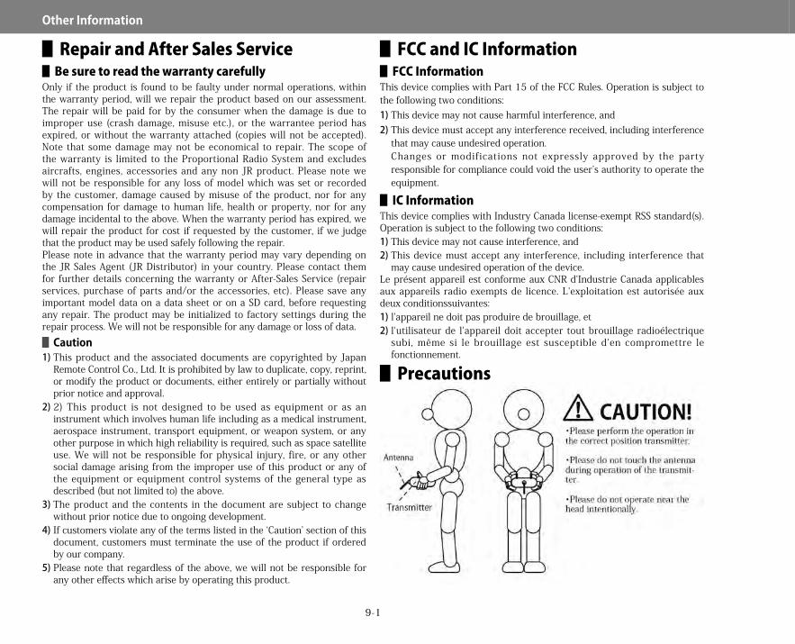
9-1
Other▋Information
▋Repair and After Sales Service▋▋Be▋sure▋to▋read▋the▋warranty▋carefully
Only if the product is found to be faulty under normal operations, within the warranty period, will we repair the product based on our assessment. The repair will be paid for by the consumer when the damage is due to improper use (crash damage, misuse etc.), or the warrantee period has expired, or without the warranty attached (copies will not be accepted). Note that some damage may not be economical to repair. The scope of the warranty is limited to the Proportional Radio System and excludes aircrafts, engines, accessories and any non JR product. Please note we will not be responsible for any loss of model which was set or recorded by the customer, damage caused by misuse of the product, nor for any compensation for damage to human life, health or property, nor for any damage incidental to the above. When the warranty period has expired, we will repair the product for cost if requested by the customer, if we judge that the product may be used safely following the repair.Please note in advance that the warranty period may vary depending on the JR Sales Agent (JR Distributor) in your country. Please contact them for further details concerning the warranty or After-Sales Service (repair services, purchase of parts and/or the accessories, etc). Please save any important model data on a data sheet or on a SD card, before requesting any repair. The product may be initialized to factory settings during the repair process. We will not be responsible for any damage or loss of data.▋▋Caution
1)This product and the associated documents are copyrighted by Japan Remote Control Co., Ltd. It is prohibited by law to duplicate, copy, reprint, or modify the product or documents, either entirely or partially without prior notice and approval.
2)2) This product is not designed to be used as equipment or as an instrument which involves human life including as a medical instrument, aerospace instrument, transport equipment, or weapon system, or any other purpose in which high reliability is required, such as space satellite use. We will not be responsible for physical injury, fire, or any other social damage arising from the improper use of this product or any of the equipment or equipment control systems of the general type as described (but not limited to) the above.
3)The product and the contents in the document are subject to change without prior notice due to ongoing development.
4)If customers violate any of the terms listed in the ‘Caution’ section of this document, customers must terminate the use of the product if ordered by our company.
5)Please note that regardless of the above, we will not be responsible for any other effects which arise by operating this product.
▋FCC and IC Information▋▋FCC▋Information
This device complies with Part 15 of the FCC Rules. Operation is subject to the following two conditions:1)This device may not cause harmful interference, and2)This device must accept any interference received, including interference
that may cause undesired operation.Changes or modifications not expressly approved by the party responsible for compliance could void the user’s authority to operate the equipment.
▋▋IC▋InformationThis device complies with Industry Canada license-exempt RSS standard(s). Operation is subject to the following two conditions:1)This device may not cause interference, and2)This device must accept any interference, including interference that
may cause undesired operation of the device.Le présent appareil est conforme aux CNR d'Industrie Canada applicables aux appareils radio exempts de licence. L'exploitation est autorisée aux deux conditionssuivantes:1)l'appareil ne doit pas produire de brouillage, et2)l'utilisateur de l'appareil doit accepter tout brouillage radioélectrique
subi, même si le brouillage est susceptible d'en compromettre le fonctionnement.
▋Precautions
28X_EN.indd 1 2015/02/27 13:42

28X_EN.indd 2 2015/02/27 13:42

The contents and specifications are subject to change without notice.
http://www.jrpropo.comOperation Manual Please read this manual thoroughly before use.
Keep this manual in a convenient place for quick and easy reference.
Operaton M
anual
■Pantone 442c■Pantone Black6c ■Pantone 485cData : 28Xman_H
Date : 20141119
Size : 185-230mm
28X_EN.indd 3 2015/02/27 13:42


