49
IOWA BYWAYS SIGNAGE POLICY 800 Lincoln Way Ames, Iowa Revised September 2015

IOWA BYWAYS
SIGNAGE POLICY
800 Lincoln Way
Ames, Iowa
Revised September 2015

ii
Page intentionally blank

iii
Contents INTRODUCTION 1 Policy Basis 1 1
Additional Iowa Byways Program Signage Resources 2
GRAPHIC IDENTITY FOR IOWA BYWAYS 3
Basic Principals 3 BYWAY GUIDE SIGNS FOR ROUTE MARKINGS 5
Byway Guide Sign Installation Guidelines 5
Byway Guide Sign Mounting Requirements 6
Byway Guide Sign Placement 6
Longitudinal Placement 6
Lateral Placement 7
Mounting Height 8
Byway Guide Sign Assemblies Supplement Route Guide Sign Assemblies 9
Directional Assembly for Byways 9
Junction Assembly for Byways 10
Confirming or Reassurance Assemblies for Byways 11
Loop Indicators 11
FIGURES FOR IOWA BYWAY GUIDE SIGNS 12
Auxiliary Sign Dimensions MUTCD Change 12 Metal Poles 12
Figure 1: Iowa Byways – System-wide Graphic Identity 13
Figure 2: Iowa Byways – System-wide Graphic Identity Color 14
Figure 3: Iowa Byways – System-wide Graphic Identity Proportions 15
Figure 4: Individual Byway Graphic Identities 16
Figure 5: Iowa Byway guide Sign Dimensions 17
Figure 6: Typical Byway Guide Sign Assemblies Illustrating Placement with
Adjoining Route Guide Sign Assemblies 18
Figure 7: Iowa Byway Guide Sign with Loop Indicator 21
Figure 8: Iowa Byway Guide Sign Use of the National Scenic Byways Sign 22
Figure 9: Typical Byway Guide Signs at Primary Highway Intersections –
Example A 23
Figure 10: Typical Byway Guide Signs at Primary Highway Intersections –
Example B 24
Figure 11: Typical Byway Guide Signs at Primary Highway Intersections –
Example C 25

iv
Figure 12: Typical Byway Guide Signs at Intersection of Primary and Secondary
Road – Example A 26
Figure 13: Typical Byway Guide Signs at Intersection of Primary and Secondary
Road – Example B 27
Figure 14: Typical Byway Guide Signs at Intersection of Primary and Secondary
Road – Example C 28
Figure 15: Typical Byway Guide Signs at Intersection of Primary with Primary and
Secondary Road – Example A 29
Figure 16: Typical Byway Guide Signs at Intersection of Primary with Primary and
Secondary Road – Example B 30
Figure 17: Typical Byway Guide Signs at Intersection of Primary with Primary and
Secondary Road – Example C 31
Figure 18: Delaware Crossing Scenic Byway Graphic Identity Specifications 32
Figure 19: Driftless Area Scenic Byway Graphic Identity Specifications 33
Figure 20: Glacial Trail Scenic Byway Graphic Identity Specifications 34
Figure 21: Grant Wood Scenic Byway Graphic Identity Specifications 35
Figure 22: Historic Hills Scenic Byway Graphic Identity Specifications 36
Figure 23: Iowa Great River Road National Scenic Byway Graphic Identity
Specifications 37
Figure 24: Iowa Valley Scenic Byway Graphic Identity Specifications 38
Figure 25: Lincoln Highway Heritage Byway Graphic Identity Specifications 39
Figure 26: Loess Hills National Scenic Byway graphic Identity Specifications 40
Figure 27: River Bluff Scenic Byway Graphic Identity Specifications 41
Figure 28: Western Skies Scenic Byway Graphic Identity Specifications 42
REFERENCES 43
CREDITS 44

1
INTRODUCTION
This Iowa Department of
Transportation policy manual has
been prepared, adopted and revised
to meet the growing interest and
needs of travelers for consistent
visual image and effective
wayshowing tools that identify
Iowa’s designated byways. The
previous Iowa Byways graphic
identity served a useful life and has
been phased out of public
presentation and use at all levels.
This manual presents the updated, approved and official graphic imagery and
design, application standards, and shared organizational responsibilities for new
Iowa Byways graphic identity. This manual supports safe, educational, and
enjoyable experiences for visitors to Iowa’s most treasured roads.
Policy Basis 1
This policy manual is supported by Chapter 306 D of the Iowa Code and Chapter
132, Iowa Scenic Byway Program of the Iowa Administrative Rules. In turn, this
Iowa Byways Signage policy is consistent and integrated with the Traffic and
Safety Manual (http://www.iowadot.gov/traffic/manuals/tsmanual.aspx)
and the Design Manual (http://www.iowadot.gov/design/dmanual/manual.html)
of the Iowa Department of Transportation. Furthermore, this manual reflects the
guidance provided by the Manual on Uniform Traffic Control Devices (MUTCD)
(http://mutcd.fhwa.dot.gov/kno_2009.htm).
Adherence to the standards (assuring that all provisions are fulfilled and any
deviations are approved only to meet a unique need or situation) set forth in this
manual will be essential to achieving success from the public investment of human
and financial resources in Iowa’s Byways.
This manual is intended to meet the needs of those who are directly responsible for
implementing, installing and sustaining the graphic identify of the collection of Iowa
Byways as well as the unique graphic identities approved for each individual byway.
Previous Iowa Byways Signage circa 2009

2
These audiences include:
Officials and personnel of the Iowa Department of Transportation including
District office.
County and municipal-level officials and personnel who are responsible for
signage on public roads, streets and arterials that are designated as Iowa
Byways.
Metropolitan Planning Organizations (MPOs); Regional Planning Affiliations
(RPAs); and Resource Conservation and Development organizations (RC&Ds)
that play an important role in planning, managing and sustaining Iowa
Byways.
Individual byway organizations and committees.
The Iowa Division of Tourism within the Iowa Department of Economic
Development.
Regional tourism organizations.
Managers of sites and attractions which present scenic, heritage, cultural,
historic and other types of intrinsic resources of a byway.
This manual provides:
The design of the approved graphic identities for the Iowa Byways collection
as well as the individual byways. These graphic designs have been officially
approved for use in street, road, and highway signs; public exhibit panels for
visitor orientation and interpretation; printed brochures; web sites and other
appropriate uses.
Guidelines for color, font, size, backgrounds, and relative placement of
graphics.
Guidelines of the location of the byway signage in the public right-of-way.
Specifications and guidelines for material options and alternatives.
The terms “scenic byway,” “byway,” “heritage byway,” and “Iowa Byway,” as used
in this manual and its references, are intended to have the same meaning.
Additional Iowa Byways Program Signage Resources
The Iowa Byways Program provides additional guidelines for sign replacement and other program information here: http://www.iowadot.gov/iowasbyways/index.aspx
Local jurisdiction signing agreements
Individual Iowa Byways brand guidelines
Sign inventory and replacement

3
GRAPHIC IDENTITY FOR IOWA BYWAYS
Basic Principles
By recognizing the informational needs associated with travel, one must assume
that consistent graphic identities would assist in creating positive memories. The
Iowa Department of Transportation recognizes that effective graphic identity needs
to be associated with Iowa Byways for several reasons:
The experiences that Iowa Byways provide Iowans and state visitors are
important sources of education, enjoyment, community pride, and economic
activity. The graphic imagery associated with Iowa Byways should support
these desirable outcomes.
A quality graphic identity can suggest (or symbolize a brand of) the essence
of what a byway and a collection of byways represent. In promoting Iowa
Byways as travel destinations, an effective graphic identity plays an
important role for prospective byway visitors in making decisions about
where and how to spend their time.
A consistent and reliable graphic identity is an essential tool that byway
travelers rely on to successfully and safely self-navigate byway routes which
are, for most byway travelers, coursed through unfamiliar landscapes, towns,
and cities. To be an effective guidance tool, byway graphic identities must
be guided by the same principle requirements that guide all traffic control
devices (MUTCD):
o Fulfill a need
o Command attention
o Convey a clear, simple meaning
o Command respect from road users
o Give adequate time for proper response
These principles must underlie the design, placement, and maintenance of all
byway signage and the graphic identities they support.
The Iowa Byways Program will express several fundamental characteristics in the
signage associated with Iowa Byways.
1. While each Iowa Byway possesses unique characteristics, Iowa Byways
represent a collection of assets and the expression of the collection’s
“wholeness” is valuable and greater than any one byway. The overarching

4
characteristic of the “collection” is expressed graphically and with the words
“Iowa Byways”. See Figures 1, 2, 3 and 4.
2. Iowa Byways are distinguished as being either “Scenic” aesthetic beauty
(visual resources that make up the primary intrinsic qualities) of the entire
viewshed or singular elements in the viewable landscape as witnessed from
the designated road or “Heritage” (historic or cultural resources that make up
the primary intrinsic qualities of the byway). The expression of these
distinctions is critical in establishing authenticity to a visitor’s experience of
driving a particular byway. This characteristic is expressed with words
“Scenic” or “Heritage” associated with the name of individual byways.
3. Most importantly, each Iowa Byway has its own distinction and uniqueness
which needs to be graphically identified. The Iowa Great River Road and the
Lincoln Highway have graphic identities that symbolize their intrinsic qualities
that extend beyond the borders of Iowa. A unique graphic image and the
name of the byway will be expressed in byway signage. The graphic
identities for each individual Iowa Byway are shown in Figures 4 and 18
through 28.
4. If an Iowa Byway attains the rare designation of “National Scenic Byway” or
“All American Road,” it is granted the right by the Federal Highway
Administration to exhibit the America’s Byways® graphic as an indication of
this important recognition (see Figure 8). The application of the America’s
Byways graphic, as an auxiliary sign (MUTCD D6-4a) in Iowa Byway signage,
will be reserved as a special identifier at intersections with primary highways
and at other important entrances and exits to those Iowa Byways that are
nationally designated.

5
BYWAY GUIDE SIGNS FOR ROUTE MARKING
This section describes the standards and uniformity for Byway Guide signs that
shall be located within the right-of-way of all primary roads, secondary roads, and
city streets that are designated Iowa Byways. Byway Guide signs are essential to:
1. informing motorists of the designation of routes as Iowa Byways;
2. guiding byway travelers along the multiple routes that comprise a designated
byway;
3. informing byway users of entrances and exits on a byway; and
4. directing byway travelers to specific attractions related to a byway route.
Iowa Byways guide signing is primarily for the purposes of providing a safe
traveling environment as well as orienting and directing road users who are not
familiar with the byway route or the area surrounding the byway. Iowa Byways
guide signs are solely for the purpose of route marking and are not an advertising
medium.
Byway Guide signs shall, where appropriate, supplement and be added to route
sign assemblies on primary roads, secondary roads, and city streets, as specified in
the Traffic and Safety Manual
(http://www.iowadot.gov/traffic/manuals/tsmanual.aspx) and applicable county
and city road and street sign policies for designated Iowa Byways.
Byway Guide signs shall not interfere with the placement and location of regulatory
and warning signs. Byway Guide signs shall be retroreflective to show similar
shape, color, and message by both day and night.
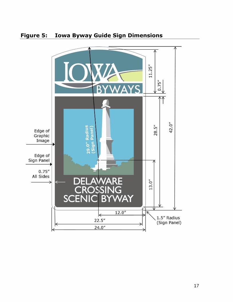
Byway Guide signs shall exhibit: 1) the Iowa Byways graphic identity, 2) the
individual byway graphic identity, and 3) the designated byway name. See Figures
1 and 4. See Figure 5 for Byway Guide Sign dimensions.
Byway Guide Sign Installation Guidelines
The guidelines contained in this policy, as well as the figures contained herein, and
applicable portions of sections 2A-7, 2A-8, 2A-9 and 2A-10 of the Traffic and
Safety Manual (http://www.iowadot.gov/traffic/manuals/tsmanual.aspx), are
intended to give field personnel the information needed to install and maintain
Byway Guide signs on the primary road system, secondary roads, local roads, and
city streets that are designated as Iowa Byways. The applicable sections of the
Traffic and Safety Manual include post mounting supports, longitudinal location

6
of signs along a roadway, lateral placement of signs, sign mounting height, and
details on hardware as well as assembly and sign maintenance.
These guidelines have been developed to supplement the MUTCD and supersede all
previous procedures, instructions, and memorandums relative to byway sign
installation and maintenance.
The contents of this policy reflect the latest information available concerning Byway
Guide sign installation and maintenance. It is the governing jurisdiction’s
responsibility to reconcile any discrepancies with other publications concerning the
topics covered and referenced herein with the approval of the Iowa Byways
Program Coordinator. The Iowa Byways Program Coordinator will provide
assistance at the request of the District Office and local jurisdictions.
Byway Guide Sign Mounting Requirements
The guidelines and requirements of the Traffic and Safety Manual, Chapter 2—
Signing, 2A – General, Mounting Requirements (2A-7)
(http://www.iowadot.gov/traffic/manuals/pdf/02a-07.pdf), and its subsequent
updates, shall apply to the mounting of individual Byway Guide signs as well as
Byway Guide Sign Assemblies associated with Route Sign Assemblies.
Byway Guide Sign Placement
Byway Guide signs should be located on the right side of the roadway where they
are easily recognized and understood by road users. Byway Guide signs should be
installed on posts and with mountings to supplement and be part of route marker
and directional guide signs referred to herein as Route Guide Sign Assemblies. In
cases where there are already two numbered route markers in a Route Guide Sign
Assembly, certain Byway Guide Sign Assemblies may/should be installed on a
separate post from the Route Guide Sign Assembly. The State Traffic Engineer will
provide assistance for individual cases at the request of the District Office for
primary routes.
Longitudinal Placement
The location of Byway Guide signs and assemblies should be placed adjacent to
Route Guide Sign Assemblies. If engineering judgment indicates that a Byway
Guide sign assembly cannot be located adjacent to Route Guide Sign Assemblies,
alternative placement shall be considered.
For alternate placement, the roadway cross section should be considered first.
Select a location where the sign can be offset the desired distance without
encountering a severe fill section requiring long posts or a cut section where the

7
sign cannot be offset at the proper mounting height. If available, a relatively level
section is preferred. Locations behind existing guardrails or barriers should be
considered to take advantage of protected areas.
Check to see if there are physical features that may obstruct visibility of the sign.
Examples are trees, mailboxes, vertical or horizontal curves, utility or luminaire
poles, bridge piers and abutments and other essential signs. Locations must be
adjusted to points where these features are not obstructions. In some cases, it
may be necessary to clear obstructions. Care should be taken to see that the shape
or outline of a sign is not obscured when mounting signs back-to-back.
Normally, the minimum longitudinal spacing of signs is 300 feet on two-lane and
four-lane undivided roadways and 800 feet on four-lane divided roadways. At
intersections and in urban areas where room is limited, it may be necessary to
reduce spacing. In sections with reduced speed limits, spacing of five times the
posted speed limit is desirable, but conditions may limit spacing to as little as three
times the posted speed limit. Uniform spacing enhances the effectiveness of a
series of signs. Spacing is important to allow signs to be viewed without
obstructing one another and to allow the motorist time to read and understand the
message conveyed before encountering another sign.
Lateral Placement
Signs on all newly constructed highways are to be offset from the traveled way if
practical. This concept is to be extended to all signs that are replaced or are
otherwise in need of attention by maintenance personnel.
The shape of the cross section, available right of way, maximum length of posts
available and condition of the soil to resist wind load, control the permissible offset.
Good signing practice requires that signs be at least 6 feet from the edge of the
shoulder and at least 12 feet from the edge of the traveled way. Taking into
consideration all of the above factors, offsets prescribed below should be used for
all signs in rural areas except those in special categories covered later in this
section.
Type of Offset Distance from Edge of the Traveled Way
to Near Post
Minimum 18 feet
Desirable 24 feet
Offsets should be measured from the edge of the pavement in all cases, regardless
of the shoulder width. The offset distances are to the post for a single support

8
assembly or the near post for a multiple support assembly. Although the near edge
of the sign projects closer to the roadway, offset distances will provide more than
the minimum distances prescribed in the MUTCD.
Depending on shoulder width, these offsets will result in approximately 12 feet of
clearance from the edge of the shoulder to the near edge of the sign. A distance of
approximately 14 feet is provided from the shoulder edge to the signpost to provide
a recovery area for errant vehicles, to allow for mowing and snow plowing, and to
keep the signs cleaner.
The desirable 24-foot offset (from the pavement) should be used in most normal
cases. Where site conditions do not permit this offset, the 18-foot minimum may
be used. It is recognized that there may be unusual circumstances where these
distances cannot be attained. For special cases, the near edge of the sign should
be installed not less than 6 feet from the edge of the shoulder.
In urban areas, signs may be installed on existing utility and light poles when space
for installing posts is otherwise not available. Permission and documentation of the
approval to use this facility should be obtained from the owner before installing
signs. A minimum offset of 2 feet from the face of the curb to the near edge of the
sign should be maintained if practical.
Mounting Height
On two-lane routes in rural areas, the MUTCD specifies that signs be mounted at a
height of at least 5 feet measured from the bottom of the sign to the near edge of
the pavement. In urban areas or locations where parking or pedestrian movements
are likely to occur or where there are other obstructions to view, the clearance from
the bottom of the sign to the curb or ground at the base of the sign shall be at least
7 feet. When a secondary sign is mounted below another sign, the mounting
heights prescribed above may be reduced to 4 feet in rural areas and 6 feet in
urban areas. For the purpose of this section, a Byway Guide Sign Assembly is
treated as a single sign. The mounting heights presented above are considered
minimums.
It is recognized that signs cannot be installed precisely at the above stated heights,
therefore a mounting tolerance of 6 inches is allowed. The above mounting heights
are considered minimums. As an example, the permissible range in mounting
height for a rural area would be from 5 feet, 0 inches to 5 feet, 6 inches.

9
Byway Guide Sign Assemblies Supplement Route Guide
Sign Assemblies
Iowa Byways shall be marked with Byway Guide Sign Assemblies within the right-
of-way of all primary roads, secondary roads and city streets that are designated
Iowa Byways. An Iowa Byway Guide Sign Assembly is the Iowa Byway Guide sign
combined with, when needed, an auxiliary sign that further identifies the byway’s
route and indicates the direction to follow. The placement of Byway Guide
Assemblies shall be adjacent to and to the right of Route Guide Sign Assemblies.
Route Guide Sign Assemblies are prescribed in Traffic and Safety Manual,
Chapter 2—Signing, 2A – General, Sign Placement (2A-8).
Iowa Byway Guide Signs and appropriate auxiliary signs shall be placed adjacent to
Route Guide Signs so as to supplement these standard guide sign functions:
Directional Assemblies consisting of the appropriate Iowa Byway Guide Sign
and related auxiliary sign(s);
Junction Assemblies consisting of the appropriate Iowa Byway Guide Sign
and related auxiliary sign(s) only at intersections where directional assembly
is not installed; and
Confirming or Reassurance Assemblies consisting of the appropriate Iowa
Byway Guide Sign.
Iowa Byway Guide Sign Assemblies shall be grouped with Route Guide Sign
Assemblies. If engineering judgment indicates that groups of assemblies that
include overlapping routes or multiple turns might be confusing, alternative
placements shall be considered provided that clear directions are given to road
users following the byway route.
See Figure 6 for illustrations of typical Route Guide Sign and Byway Guide Sign
Assemblies.
Directional Assembly for Byways
For routes that are designated Iowa Scenic and/or Heritage Byways, a Directional
Assembly consists of 1) a Route Guide Sign Assembly and 2) a Byway Guide Sign
Assembly and its attendant directional arrow auxiliary sign. A Directional Assembly
for a byway marks the turn movements that are required to follow the byway route.
See Figures 6A and 9 through 17.
The Byway Guide Sign Assembly shall consist of 1) the Iowa Byways graphic
identity; 2) the individual byway graphic identity; and 3) the individual byway or
byway loop name. The Byway Guide Sign Assembly shall be positioned to the right
of the Route Sign Assembly. In extremely rare locations where horizontal space is

10
limited, the Byway Guide Sign Assembly may be mounted below the Route Sign
Assembly based on appropriate engineering judgment. See Figure 6A.1.
For Iowa Byways that are also designated as “National Scenic Byway” or “All-
American Road” by the Federal Highway Administration, the National Scenic Byways
Sign (D6-4a) may be attached below the Byway Guide Sign as part of a Directional
Assembly. Placement of the National Scenic Byways Sign shall be limited to
Directional Assembly signs installed in advance of an intersection where a
numbered route is intersected or joined by a route that is designated a National
Scenic Byway or an All American Road by the Federal Highway Administration. See
Figure 8 for typical mounting arrangement.
Junction Assembly for Byways
A Byway Guide Sign Assembly shall be installed with a route guide Junction
Assembly only if a Directional Assembly is not installed at an intersection for routes
that are designated Iowa Scenic and/or Heritage Byways. A Junction Assembly
consists of 1) a Junction Auxiliary sign; 2) a U.S., State, and/or County route sign;
and 3) a Byway Guide Sign Assembly that includes the Byway Guide sign and its
attendant Junction Auxiliary sign. The route sign shall carry the number of the
intersected or joined route. See Figure 6B.
The Byway Guide Sign Assembly shall consist of 1) the Iowa Byways graphic
identity; 2) the individual byway graphic identity; and 3) the individual byway or
byway loop name. The Byway Guide Sign Assembly shall be positioned to the right
of the route sign assembly. In extremely rare locations where horizontal space is
limited, the Byway Guide Sign Assembly may be mounted below the route sign
assembly based on appropriate engineering judgment. See Figure 6B.1.
The Junction Assembly shall be installed on a secondary road in advance of an
intersection where the secondary road is intersected or joined by a primary road
and an Iowa Byway. See Figures 12 through 17.
For Iowa Byways that are also designated as “National Scenic Byway” or “All-
American Road” by the Federal Highway Administration, the National Scenic Byways
Sign (D6-4a) may be attached below the Byway Guide Sign as part of a Junction
Assembly if a Directional Assembly is not present at an intersection. Placement of
the National Scenic Byways Sign shall be limited to Directional or Junction Assembly
signs installed in advance of an intersection where a numbered route is intersected
or joined by a route that is designated a National Scenic Byway or an All American
Road by the Federal Highway Administration. See Figure 8.

11
Confirming or Reassurance Assemblies for Byways
Confirming or Reassurance Assemblies for Byways consist of 1) a Route Guide Sign
Assembly and 2) a Byway Guide Sign Assembly. See Figure 6C.
The Byway Guide Sign Assembly shall consist of 1) the Iowa Byways graphic
identity; 2) the individual byway graphic identity; and 3) the individual byway or
byway loop name. The Byway Guide Sign Assembly shall be positioned to the right
of the route sign assembly. In extremely rare locations where horizontal space is
limited, the Byway Guide Sign Assembly may be mounted below the route sign
assembly based on appropriate engineering judgment. See Figure 6C.1
The Confirming Assembly shall be erected just beyond primary-to-primary,
primary-to-secondary, secondary-to-primary, and secondary-to-secondary
intersections of numbered routes to inform motorists of the route they have turned
onto. See Figures 6C and 9 through 17.
Reassurance Assemblies should be spaced at such intervals as necessary to keep
drivers informed of their route. For the benefit of traffic entering from paved
secondary routes, Reassurance Assemblies for the primary route and byway shall
be placed for both directions of traffic. They should also be placed at unpaved
intersections on alternating sides of the primary highway. However, in areas with
closely spaced intersections it is not necessary to have Reassurance Assemblies at
each of them as long as the minimum spacing is approximately two miles. In urban
areas Reassurance Assemblies should be erected just beyond major intersections
and at intervals of about six city blocks.
Loop Indicators
Some Iowa Byways have officially designated secondary routes known as “Loops”.
For byway routes that are designated as Loops, a Loop Indicator graphic shall be
included in the Byway Guide sign as indicated in Figure 7. Application of the Loop
Indicator is appropriate for Directional Assemblies, Junction Assemblies, Confirming
Assemblies, and Reassurance Assemblies.
The Loop Indicator graphic is a diagonal band containing the word “LOOP” placed in
the upper left corner of the byway graphic identity as indicated in Figure 7.
Typeface for the loop name shall be Gills Sans set in all caps and printed white on
the black background.
If an Iowa Byway Loop has a name approved by the Iowa Byways Program
Coordinator, the loop name may be printed on the Byway Guide sign in lieu of the
designated byway name.

12
FIGURES FOR IOWA BYWAY GUIDE SIGNS
Refer to the following figures and appropriate figures of the Traffic and Safety
Manual for proper and official fabrication and installation of Iowa Byway Guide Sign
Assemblies. These figures are not all to scale.
Auxiliary Sign Dimensions
September 2015
Many of the MUTCD auxiliary sign size standards have changed since the assembly
figures were developed. This chart provides the updated standard dimensions. The size of these auxiliary signs may affect the appearance of the configurations in new
and replacement installations.
Metal Poles
Beginning with the 2016 construction season, the Iowa DOT will require Perforated
Square Steel Tube (PSST) posts for new sign installations.

13
Figure 1: Iowa Byways—System-wide Graphic Identity
System-wide Graphic Identity
System wide Graphic identify in combination with individual byway graphic
identity
The Iowa Byways system-wide graphic identity is single image that represents the
comprehensive family of Iowa Byways. It can be a stand-alone graphic for
identifying and promoting the Iowa Byways program. It combines with individual
byway graphic identities on highway guide signage. The system-wide identity
graphic is an intentionally simple graphic style that is a recognizable and
memorable graphic theme without competing with or dominating the individual
byway graphic identity when displayed on wayshowing signage. The colors and
curves in the graphic identity are an abstraction of the undulating Iowa landscape.
These colors serve as the primary color palette for the Iowa Byways brand.

14
Figure 2: Iowa Byways—System-wide Graphic Identity
Color
The typeface for “IOWA” is a derivation of Cheltenham BT set in all caps. The
original typeface is manipulated to blend with abstract graphic representations of
hills and valleys. Typeface for “BYWAYS” is Gill sans set in all caps.
Colors for the brand identity are Light Blue (C100 M60 Y50) or PMS equivalent,
Dark Blue (C100 M90 Y70) or PMS equivalent, and green (C40 M20 Y80) or PMS
equivalent.

15
Figure 3: Iowa Byways—System-wide Graphic Identity
Proportions
The proportion of the system-wide identity graphic is created in a ratio of 1.0
(height) to 1.5 (width). Any enlargement or reduction of the graphic identity must
maintain the ratio. At a ratio of 1.0 to 1.5, the radii of the arcs comprising the top
and bottom of the mark = 2.0.

16
Figure 4: Individual Byway Graphic Identities
The graphic identities for the individual byways in the Iowa Byways program were
developed in an intentionally simple graphic style so as to be a recognizable and
memorable graphic theme, descriptive of the character and experience of the
byway, and as a safe and effective wayshowing tool when displayed on highway
guide signs.
17
Figure 5: Iowa Byway Guide Sign Dimensions

18
Figure 6: Typical Byway Guide Sign Assemblies Illustrating Placement with Adjoining Route
Guide Sign Assemblies
Route numbers and auxiliary signs shown are illustrated for example only. Type
and number of route and auxiliary signs are determined on a location-by-location
basis.
Note: Many of the auxiliary sign size standards have changed since the above
assembly figures were developed. See page 12 for current standards as of
September 2015.

19
Route numbers and auxiliary signs shown are illustrated for example only. Type
and number of route and auxiliary signs are determined on a location-by-location
basis.
Note: Many of the auxiliary sign size standards have changed since the above
assembly figures were developed. See page 12 for current standards as of
September 2015.

20
Route numbers and auxiliary signs shown are illustrated for example only. Type
and number of route and auxiliary signs are determined on a location-by-location
basis.

21
Figure 7: Iowa Byway Guide Sign with Loop Indicator
22
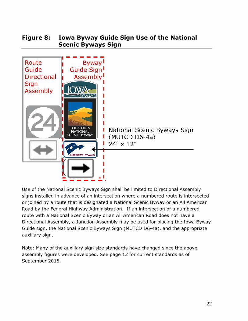
Figure 8: Iowa Byway Guide Sign Use of the National
Scenic Byways Sign
Use of the National Scenic Byways Sign shall be limited to Directional Assembly
signs installed in advance of an intersection where a numbered route is intersected
or joined by a route that is designated a National Scenic Byway or an All American
Road by the Federal Highway Administration. If an intersection of a numbered
route with a National Scenic Byway or an All American Road does not have a
Directional Assembly, a Junction Assembly may be used for placing the Iowa Byway
Guide sign, the National Scenic Byways Sign (MUTCD D6-4a), and the appropriate
auxiliary sign.
Note: Many of the auxiliary sign size standards have changed since the above
assembly figures were developed. See page 12 for current standards as of
September 2015.

23
Figure 9: Typical Byway Guide Signs at Primary Highway
Intersections—Example A
Note: Many of the auxiliary sign size standards have changed since the above assembly figures were developed. See page 12 for current standards as of September 2015.

24
Figure 10: Typical Byway Guide Signs at Primary Highway
Intersections—Example B
Note: Many of the auxiliary sign size standards have changed since the above assembly figures were developed. See page 12 for current standards as of September 2015.

25
Figure 11: Typical Byway Guide Signs at Primary
Highway Intersections—Example C
Note: Many of the auxiliary sign size standards have changed since the above assembly figures were developed. See page 12 for current standards as of September 2015.

26
Figure 12: Typical Byway Guide Signs at Intersection of
Primary and Secondary Road—Example A
Note: Many of the auxiliary sign size standards have changed since the above assembly figures were developed. See page 12 for current standards as of September 2015.

27
Figure 13: Typical Byway Guide Signs at Intersection of
Primary and Secondary Road—Example B
Note: Many of the auxiliary sign size standards have changed since the above assembly figures were developed. See page 12 for current standards as of September 2015.

28
Figure 14: Typical Byway Guide Signs at Intersection of
Primary and Secondary Road—Example C
Note: Many of the auxiliary sign size standards have changed since the above assembly figures were developed. See page 12 for current standards as of September 2015.

29
Figure 15: Typical Byway Guide Signs at Intersection of Primary with Primary and Secondary Road—
Example A
Note: Many of the auxiliary sign size standards have changed since the above assembly figures were developed. See page 12 for current standards as of September 2015.

30
Figure 16: Typical Byway Guide Signs at Intersection of Primary with Primary and Secondary Road—
Example B
Note: Many of the auxiliary sign size standards have changed since the above assembly figures were developed. See page 12 for current standards as of September 2015.

31
Figure 17: Typical Byway Guide Signs at Intersection of Primary with Primary and Secondary Road—
Example C
Note: Many of the auxiliary sign size standards have changed since the above assembly figures were developed. See page 12 for current standards as of September 2015.

32
Figure 18: Delaware Crossing Scenic Byway Graphic
Identity Specifications
The typeface for “DELAWARE CROSSING SCENIC BYWAY” is Gill Sans set in all
caps. Colors for the Delaware Crossing graphic identity:
Blue: C80 M40 Y30
Green: C90 M70 Y90
Black 1: 100%
Black 2: 30%
Black 3: 50%
Black 4: 80%
Black 5: 90%
White

33
Figure 19: Driftless Area Scenic Byway Graphic Identity
Specifications
The typeface for “DRIFTLESS AREA SCENIC BYWAY” is Gill Sans set in all caps.
Colors for the Driftless Area graphic identity:
Red: M90 Y90
Yellow: M20 Y70
Blue: C70 M20
Black
White

34
Figure 20: Glacial Trail Scenic Byway Graphic Identity
Specifications
The typeface for “GLACIAL TRAIL SCENIC BYWAY” is Gill Sans set in all caps.
Colors for the Glacial Trail graphic identity:
Blue: C50 M20 Y20
Green: C40 M20 Y80
Light Brown: M10 Y30
Dark Brown: C80 M90 Y100
Black
White

35
Figure 21: Grant Wood Scenic Byway Graphic Identity
Specifications
The typeface for “GRANT WOOD SCENIC BYWAY” is Gill Sans set in all caps. Colors
for the Grant Wood graphic identity:
Blue: C30 Y20
Yellow 1: Y10
Yellow 2: Y20
Green 1: C20 Y50
Green 2: C30 M20 Y70
Green 3: C60 M50 Y100
Green 4: C80 M70 Y100
Green 5: C70 M50 Y80
Green 6: C100 M80 Y100
Black
White

36
Figure 22: Historic Hills Scenic Byway Graphic Identity
Specifications
The typeface for “HISTORIC HILLS SCENIC BYWAY” is Gill Sans set in all caps.
Colors for the Historic Hills graphic identity:
Blue: C60 M40
Light Green: C10 Y20
Medium Green: C70 M60 Y90
Dark Green: C100 M90 Y100
Twig 1: C90 M100 Y100
Twig 2: C70 M90 Y80
Twig 3: C20 M40 Y60
Twig 4: M10 Y20
Pink 1: C40 M100 Y30
Pink 2: C20 M60
Pink 3: C20 M80
Pink 4: M40
Pink 5: M20
Pink 6: M20
Lavender 1: C20 M40
Lavender 2: C10 M30Dark
Red 1: C60 M100 Y90Dark
Red 2: C70 M100 Y90
Black
White

37
Figure 23: Iowa Great River Road National Scenic Byway
Graphic Identity Specifications
The typeface for “GREAT RIVER ROAD IOWA” is historical, unknown. The typeface
for “NATIONAL SCENIC BYWAY” is Gill Sans set in all caps. Colors for the Iowa
Great River Road National Scenic Byway graphic identity:
Green 1: C100 M80 Y100
Black
White

38
Figure 24: Iowa Valley Scenic Byway Graphic Identity
Specifications
The typeface for “IOWA VALLEY SCENIC BYWAY” is Gill Sans set in all caps. Colors
for the Iowa Valley graphic identity:
Blue: C70 M30 Y30
Yellow 1: Y10
Yellow 2: C10 M10 Y60
Yellow 3: C30 M30 Y100
Green 1: C60 M40 Y80
Green 2: C90 M70 Y90
Black
White

39
Figure 25: Lincoln Highway Heritage Byway Graphic
Identity Specifications
The typeface for “LINCOLN HIGHWAY HERITAGE BYWAY” is Gill Sans set in all caps.
Colors for the Lincoln Highway graphic identity:
Red: M100 Y100 C20
Blue: C100 M70 Y20
Black
White
NOTE: These typeface and color specifications apply when used for LOOP
identification and guide signs.
40
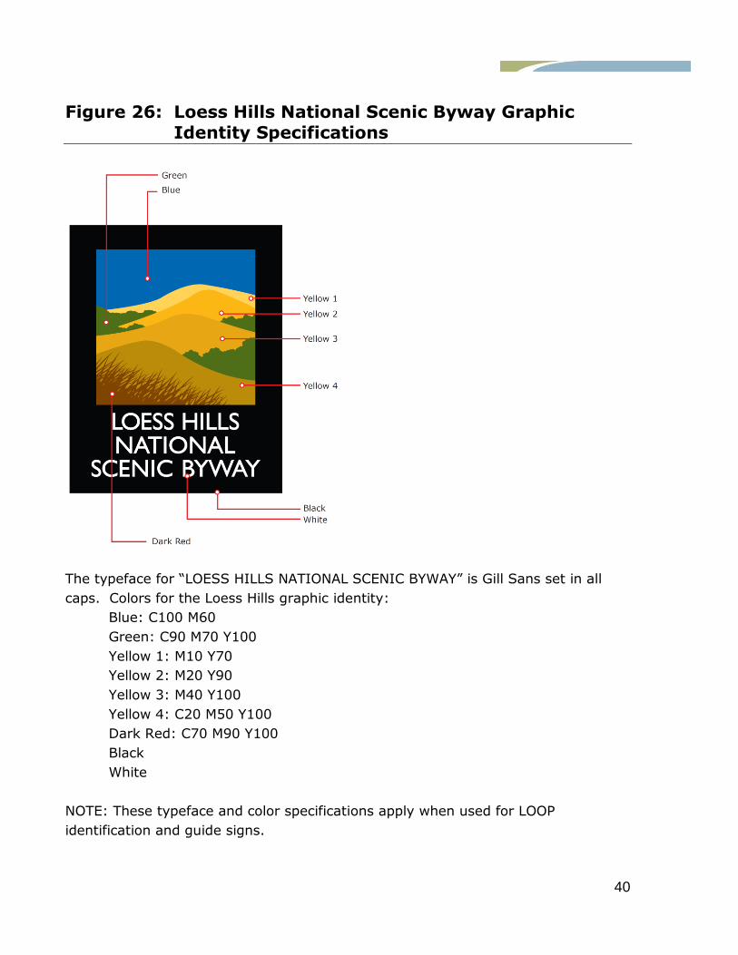
Figure 26: Loess Hills National Scenic Byway Graphic
Identity Specifications
The typeface for “LOESS HILLS NATIONAL SCENIC BYWAY” is Gill Sans set in all
caps. Colors for the Loess Hills graphic identity:
Blue: C100 M60
Green: C90 M70 Y100
Yellow 1: M10 Y70
Yellow 2: M20 Y90
Yellow 3: M40 Y100
Yellow 4: C20 M50 Y100
Dark Red: C70 M90 Y100
Black
White
NOTE: These typeface and color specifications apply when used for LOOP
identification and guide signs.

41
Figure 27: River Bluff Scenic Byway Graphic Identity
Specifications
The typeface for “RIVER BLUFFS SCENIC BYWAY” is Gill Sans set in all caps. Colors
for
the River Bluffs graphic identity:
Blue 1: C50 M10 Y20
Blue 2: C40 M10 Y10
Blue 3: C70 M30 Y30
Blue 4: C100 M70 Y50
Blue 5: C100 M80 Y70
Green 1: C100 M80 Y100
Green 2: C100 M90 Y100
Yellow 1: C10 M10 Y60
Yellow 2: C20 M20 Y70
Yellow 3: C30 M30 Y100
Black
White

42
Figure 28: Western Skies Scenic Byway Graphic Identity
Specifications
The typeface for “WESTERN SKIES SCENIC BYWAY” is Gill Sans set in all caps.
Colors for the Western Skies graphic identity:
Orange: M40 Y90
Green 1: C20 Y60
Green 2: C40 M20 Y80
Black
White

43
REFERENCES
Appropriate and applicable portions of the following documents are incorporated in
this manual by reference:
Manual on Uniform Traffic Control Devices (MUTCD), Federal Highway Administration, latest edition as referenced and currently used by the Iowa Department of Transportation
http://mutcd.fhwa.dot.gov/pdfs/2009/pdf_index.htm
Standard Highway Signs and Markings (SHSM) Book, Federal Highway Administration, latest edition as referenced and currently used by the Iowa Department of Transportation
http://mutcd.fhwa.dot.gov/ser-shs_millennium.htm
Chapter 132, Iowa Scenic Byway Program, Iowa Administration Code, latest edition http://search.legis.state.ia.us/nxt/gateway.dll/ar/iac/7610___transportation%20de
partment%20__5b761__5d/1320___chapter%20132%20iowa%20scenic%20byway%20program/_c_7610_1320.xml?f=templates$fn=document-frame.htm$3.0
Traffic and Safety Manual, Office of Traffic and Safety, Iowa Department of Transportation, latest edition
http://www.iowadot.gov./traffice/manuals/tsmanual
Design Manual, Office of Design, Iowa Department of Transportation, latest edition http://www.iowadot.gov/design/index.htm
Wayshowing for Byways–A Reference Manual, America’s Byways® Resource
Center, latest edition http://www.bywaysresourcecenter.org/
Federal Register / Vol. 60, No. 96 / Thursday, May 18, 1995, Interim Policy for the
National Scenic Byway Program, Federal Highway Administration http://assets.byways.org/asset_files/000/002/997/FedReg.pdf
Iowa Byways Program, local jurisdiction signing agreements, guidelines for sign replacement, more program information
http://www.iowadot.gov/iowasbyways/index.aspx Individual Iowa Byways Brand Guidelines – The Iowa Byways logos are
trademarked. “Word and Design Marks and Specifications for Proper Use” documents and latest editions as submitted and accepted for Trademark copyright
protection and discussed in Iowa Department of Transportation Procedures and Policy Manual Section: Trademarks No. 000.08 are available on the Iowa Byways Program web pages at http://www.iowadot.gov/iowasbyways/index.aspx

44
Iowa Great River Road Brand, The green and white “pilot’s wheel” in the Great River Road graphic is further protected by guidelines dictated by the Mississippi
River Parkway Commission. Logo Use Policy at http://mrpcmembers.com/files/MRPCLogousage.pdf
45
CREDITS
December 2010
Iowa Department of Transportation
Nancy J. Richardson, Director
Stuart Anderson
Planning, Programming and Modal Division Director
Craig Markley
Grant Team Leader Office of Systems Planning
Troy Siefert, LA
Project Manager Iowa Byways Program Coordinator Office of Systems Planning
Key participants representing the Iowa Department of Transportation included:
Tim Crouch, P.E., P.T.O.E. David Matulac, P.E. Office of Traffic & Safety Traffic Engineering (Operations)
Mark Masteller, LA
Highway Division Office of Design Roadside Development
Byway Planning Consultants:
Shive-Hattery, Inc.
1601 48th Street, Suite 200 West Des Moines, IA 50266
In association with:
David L. Dahlquist Associates, LLC
5204 Shriver Avenue Des Moines, Iowa 50312
September 2015
Tim Crouch, P.E., P.T.O.E. David Matulac, P.E. Office of Traffic & Safety Traffic Engineering (Operations)
Mary K. Stahlhut
Iowa Byways Program Coordinator
Office of Systems Planning


