General The Redwood® engine powers and communicates with Redwood gateways, sensors, and wall switches. The engine offers sophisticated controls that significantly reduce energy consumption. Multiple engines can be linked together to power and control hundreds or thousands of fixtures.
The Redwood engine centralizes power conversion and control processing for LED lighting and control and communications for other lighting technologies, including fluorescent, CFL, and HID. It takes high-voltage 120–250 VAC or 277 VAC input power, converts it to low-voltage DC, and distributes the power to all fixtures via Redwood gateways using Class 2, low-voltage cabling. The engine can be located on a rack or wall-mounted in an electrical or telecom closet.
Ordering information is listed below:
Part No. Description
RE64-2G-120-250-ROS Engine, 2G, 120–250 VAC. Includes one (1) license of the Redwood operating system (ROS) with Redwood manager software.
RE64-2G-277-ROS Engine, 2G, 277 VAC. Includes one (1) license of the Redwood operating system (ROS) with Redwood manager software.
WallMount-Tray-1G Engine wall mount kit
RPC-RJ45-1G Patch cord with RJ45 connector RPC-LSZH-RJ45-1G Patch cord (low smoke zero halogen) with RJ45 connector RPC-PD-1G Patch cord with open wire for punch down (without RJ45 connector)
Redwood® Engine
How to Contact Us • To find out more about CommScope® products, visit us on the web at www.commscope.com/
• For technical assistance:
- Within North and South America, contact your local technical manager or technical support at 1-800-840-0709 (Option 2). Outside North and South America, contact your local technical manager or technical support at +1 510-270-5360 (Option 2).
- Live technical support for Redwood products is available Monday through Friday from 8 AM to 5 PM (PST), excluding holidays.
- An email can also be sent to [email protected] for technical support.
• For installations in Canada, no uninsulated live parts in the output from the Redwood Engine can be readily accessible, as defined by the Canadian Electrical Code (CES). Accessibility is determined using the risk of shock accessibility criteria by using the finger probe from the CSA standards cited for the category associated with the C-UL Mark. Also consider access to such parts for panels that can be removed without tools. Insulated parts, such as wire or cabling with outer insulation or a jacket that is certified and carries a sufficient voltage rating (>60V), can be accessible to contact.
• If a fixture requires more than one channel for power, use additional wiring (see each fixture’s specification for requirements). All additional channels for a two- or three-channel fixture must be connected to the same engine. Wiring for an individual fixture cannot be spread across multiple engines.
• For one engine in a group of co-located engines, it is recommended that one bank of eight ports be left unused to facilitate future expansion of the system. It also provides a measure of redundancy.
• It is recommended that the fixtures in a single space be interleaved across engines to provide a level of redundancy. If an electrical failure affects an engine, only a portion of the lights in a room would turn off.
• The Redwood engine, director, sensors, gateways and wall switches are designed for commercial use only and are not for household use.
Preparation 1. Determine location for all fixtures and Redwood wall switches.
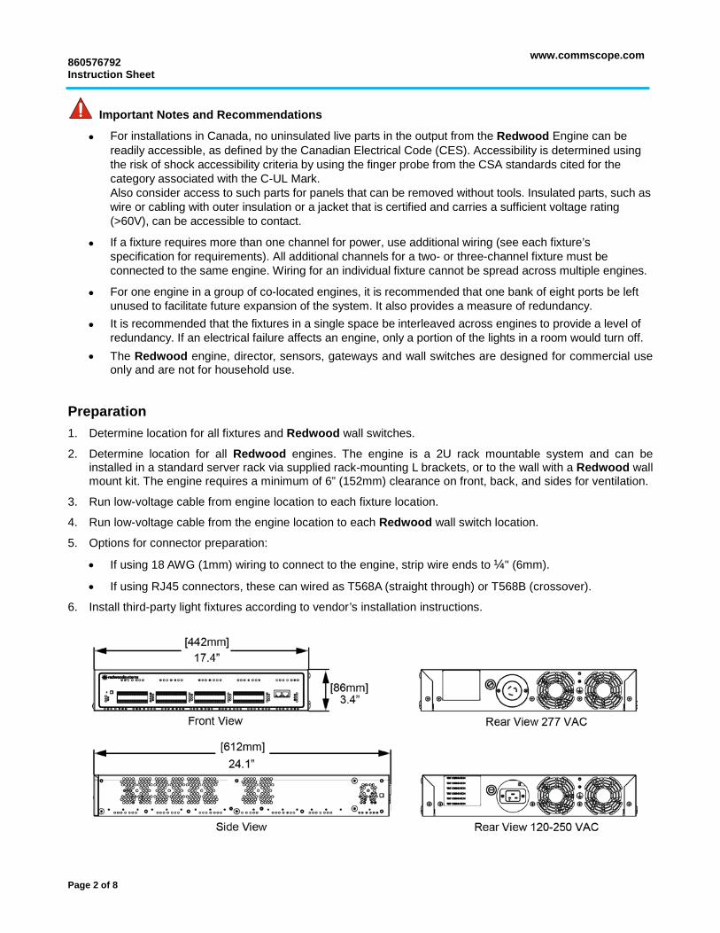
2. Determine location for all Redwood engines. The engine is a 2U rack mountable system and can be installed in a standard server rack via supplied rack-mounting L brackets, or to the wall with a Redwood wall mount kit. The engine requires a minimum of 6” (152mm) clearance on front, back, and sides for ventilation.
3. Run low-voltage cable from engine location to each fixture location.
4. Run low-voltage cable from the engine location to each Redwood wall switch location.
5. Options for connector preparation:
• If using 18 AWG (1mm) wiring to connect to the engine, strip wire ends to ¼" (6mm).
• If using RJ45 connectors, these can wired as T568A (straight through) or T568B (crossover).
6. Install third-party light fixtures according to vendor’s installation instructions.
Page 2 of 8
www.commscope.com 860576792
Instruction Sheet
Installation Rack Mount Instructions
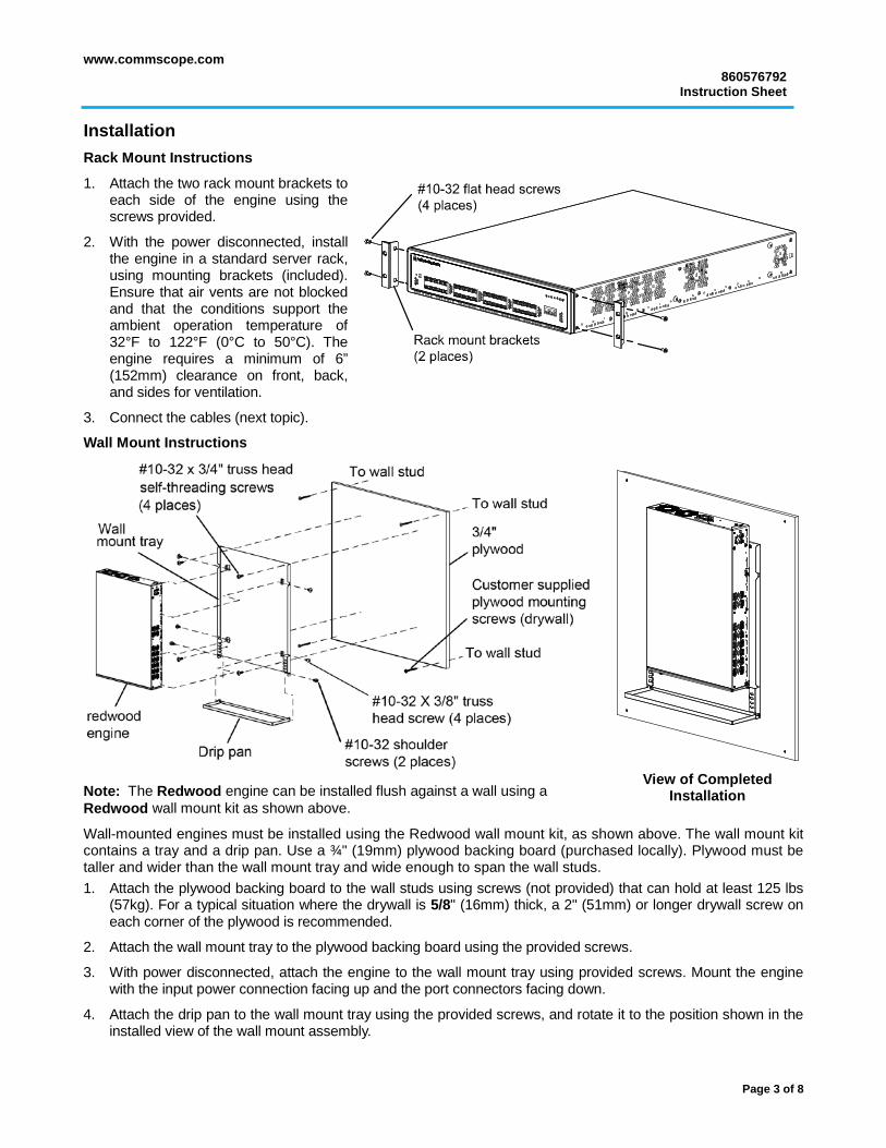
1. Attach the two rack mount brackets to each side of the engine using the screws provided.
2. With the power disconnected, install the engine in a standard server rack, using mounting brackets (included). Ensure that air vents are not blocked and that the conditions support the ambient operation temperature of 32°F to 122°F (0°C to 50°C). The engine requires a minimum of 6” (152mm) clearance on front, back, and sides for ventilation.
3. Connect the cables (next topic).
Wall Mount Instructions
Note: The Redwood engine can be installed flush against a wall using a Redwood wall mount kit as shown above.
Wall-mounted engines must be installed using the Redwood wall mount kit, as shown above. The wall mount kit contains a tray and a drip pan. Use a ¾" (19mm) plywood backing board (purchased locally). Plywood must be taller and wider than the wall mount tray and wide enough to span the wall studs. 1. Attach the plywood backing board to the wall studs using screws (not provided) that can hold at least 125 lbs
(57kg). For a typical situation where the drywall is 5/8" (16mm) thick, a 2" (51mm) or longer drywall screw on each corner of the plywood is recommended.
2. Attach the wall mount tray to the plywood backing board using the provided screws.
3. With power disconnected, attach the engine to the wall mount tray using provided screws. Mount the engine with the input power connection facing up and the port connectors facing down.
4. Attach the drip pan to the wall mount tray using the provided screws, and rotate it to the position shown in the installed view of the wall mount assembly.
View of Completed
Installation
Page 3 of 8
860576792 Instruction Sheet
www.commscope.com
Cabling
Note: If using a category cable, see the Category Cabling instructions below. If using 18 AWG wiring, see the 18 AWG (1mm) Cabling instructions on page 6.
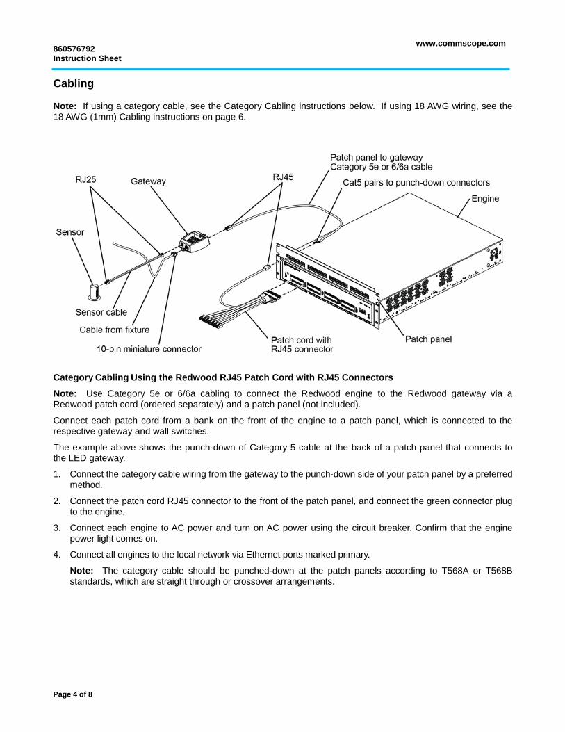
Category Cabling Using the Redwood RJ45 Patch Cord with RJ45 Connectors
Note: Use Category 5e or 6/6a cabling to connect the Redwood engine to the Redwood gateway via a Redwood patch cord (ordered separately) and a patch panel (not included).
Connect each patch cord from a bank on the front of the engine to a patch panel, which is connected to the respective gateway and wall switches.
The example above shows the punch-down of Category 5 cable at the back of a patch panel that connects to the LED gateway.
1. Connect the category cable wiring from the gateway to the punch-down side of your patch panel by a preferred method.
2. Connect the patch cord RJ45 connector to the front of the patch panel, and connect the green connector plug to the engine.
3. Connect each engine to AC power and turn on AC power using the circuit breaker. Confirm that the engine power light comes on.
4. Connect all engines to the local network via Ethernet ports marked primary.
Note: The category cable should be punched-down at the patch panels according to T568A or T568B standards, which are straight through or crossover arrangements.
Page 4 of 8
www.commscope.com 860576792
Instruction Sheet
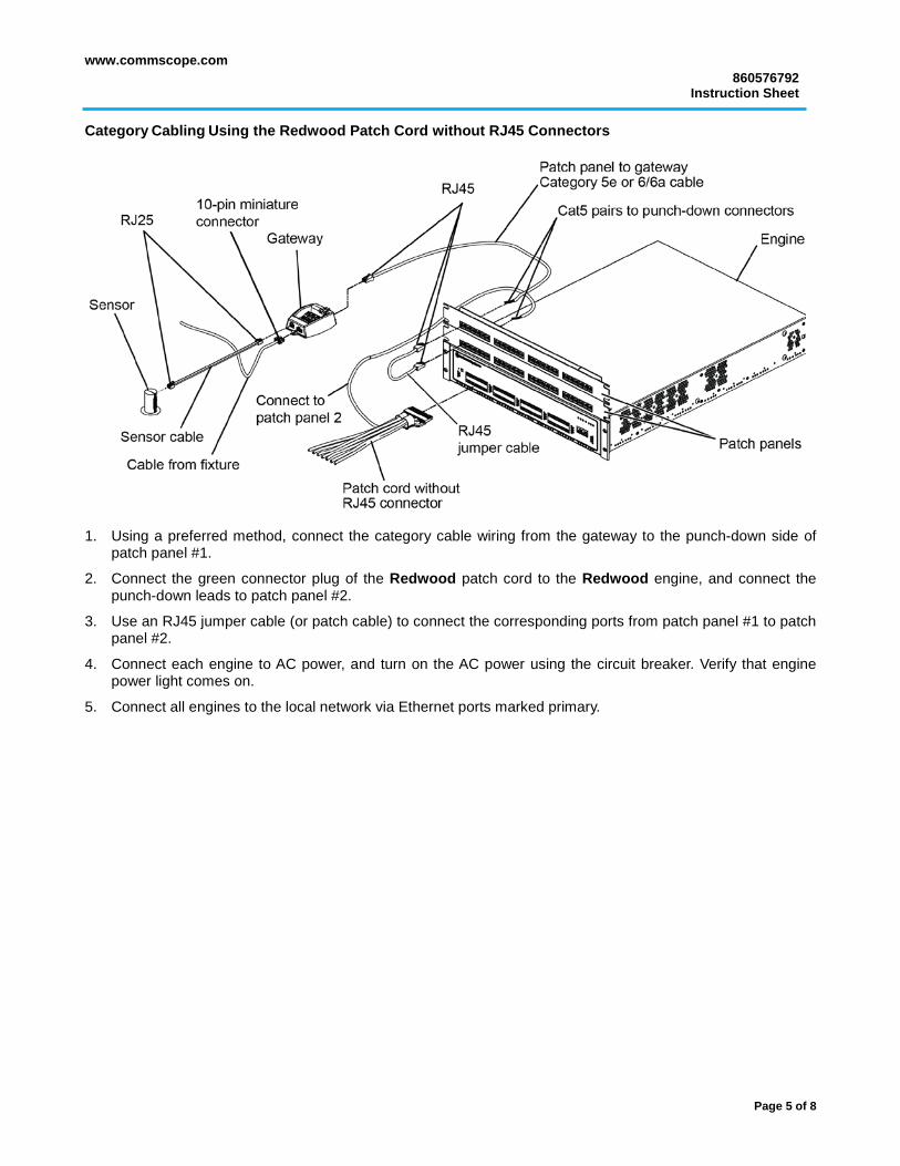
Category Cabling Using the Redwood Patch Cord without RJ45 Connectors
1. Using a preferred method, connect the category cable wiring from the gateway to the punch-down side of
patch panel #1.
2. Connect the green connector plug of the Redwood patch cord to the Redwood engine, and connect the punch-down leads to patch panel #2.
3. Use an RJ45 jumper cable (or patch cable) to connect the corresponding ports from patch panel #1 to patch panel #2.
4. Connect each engine to AC power, and turn on the AC power using the circuit breaker. Verify that engine power light comes on.
5. Connect all engines to the local network via Ethernet ports marked primary.
Page 5 of 8
860576792 Instruction Sheet
www.commscope.com
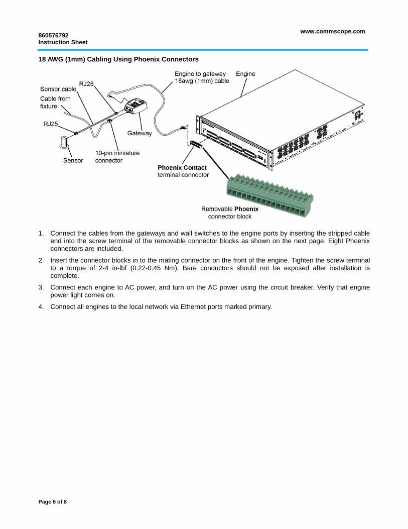
18 AWG (1mm) Cabling Using Phoenix Connectors
1. Connect the cables from the gateways and wall switches to the engine ports by inserting the stripped cable
end into the screw terminal of the removable connector blocks as shown on the next page. Eight Phoenix connectors are included.
2. Insert the connector blocks in to the mating connector on the front of the engine. Tighten the screw terminal to a torque of 2-4 in-lbf (0.22-0.45 Nm). Bare conductors should not be exposed after installation is complete.
3. Connect each engine to AC power, and turn on the AC power using the circuit breaker. Verify that engine power light comes on.
4. Connect all engines to the local network via Ethernet ports marked primary.
Page 6 of 8
www.commscope.com 860576792
Instruction Sheet
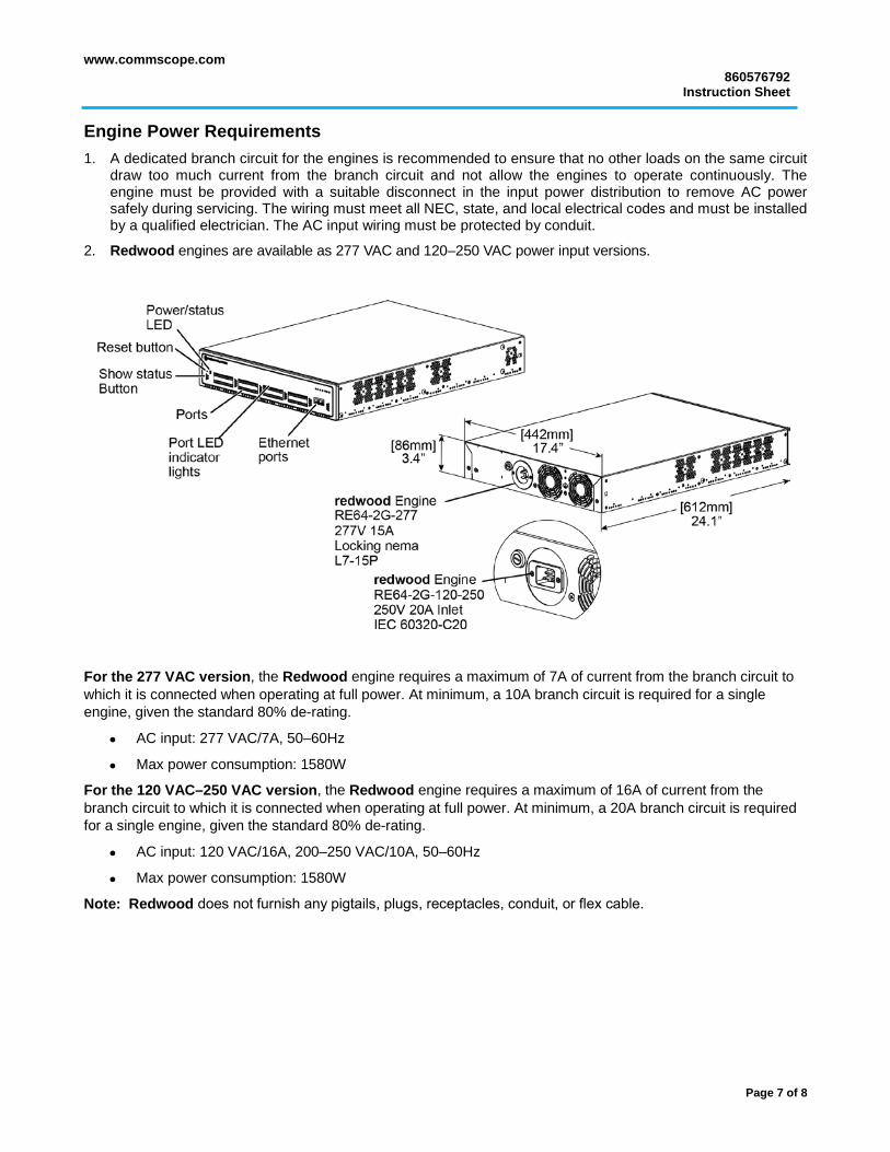
Engine Power Requirements 1. A dedicated branch circuit for the engines is recommended to ensure that no other loads on the same circuit
draw too much current from the branch circuit and not allow the engines to operate continuously. The engine must be provided with a suitable disconnect in the input power distribution to remove AC power safely during servicing. The wiring must meet all NEC, state, and local electrical codes and must be installed by a qualified electrician. The AC input wiring must be protected by conduit.
2. Redwood engines are available as 277 VAC and 120–250 VAC power input versions.
For the 277 VAC version, the Redwood engine requires a maximum of 7A of current from the branch circuit to which it is connected when operating at full power. At minimum, a 10A branch circuit is required for a single engine, given the standard 80% de-rating.
• AC input: 277 VAC/7A, 50–60Hz
• Max power consumption: 1580W
For the 120 VAC–250 VAC version, the Redwood engine requires a maximum of 16A of current from the branch circuit to which it is connected when operating at full power. At minimum, a 20A branch circuit is required for a single engine, given the standard 80% de-rating.
• AC input: 120 VAC/16A, 200–250 VAC/10A, 50–60Hz
• Max power consumption: 1580W
Note: Redwood does not furnish any pigtails, plugs, receptacles, conduit, or flex cable.
Page 7 of 8
860576792 Instruction Sheet
www.commscope.com
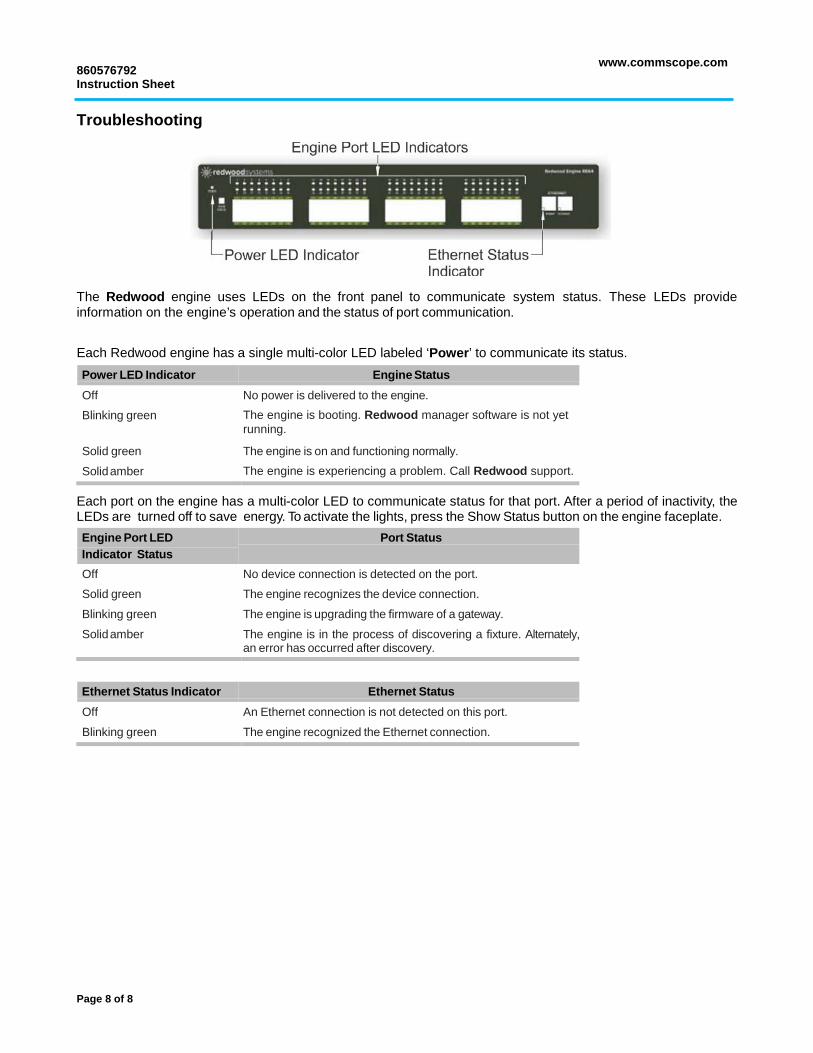
Troubleshooting
The Redwood engine uses LEDs on the front panel to communicate system status. These LEDs provide information on the engine’s operation and the status of port communication. Each Redwood engine has a single multi-color LED labeled ‘Power’ to communicate its status. Power LED Indicator Engine Status
Off No power is delivered to the engine.
Blinking green The engine is booting. Redwood manager software is not yet running.
Solid green The engine is on and functioning normally.
Solid amber The engine is experiencing a problem. Call Redwood support.
Each port on the engine has a multi-color LED to communicate status for that port. After a period of inactivity, the LEDs are turned off to save energy. To activate the lights, press the Show Status button on the engine faceplate. Engine Port LED Indicator Status
Port Status
Off No device connection is detected on the port.
Solid green The engine recognizes the device connection.
Blinking green The engine is upgrading the firmware of a gateway.
Solid amber The engine is in the process of discovering a fixture. Alternately, an error has occurred after discovery.
Ethernet Status Indicator Ethernet Status
Off An Ethernet connection is not detected on this port.
Blinking green The engine recognized the Ethernet connection.


![2G. Technical Specifications · 2G. Technical Specifications avus 1500 ... Engine-management-system: TCG2020V16 [1/min] [ - ] ... capacity required:](https://static.documents.pub/doc/80x56/5b563a4a7f8b9adf7d8c46bd/2g-technical-specifications-2g-technical-specifications-avus-1500-engine-management-system.jpg)
![The Redwood gazette. (Redwood Falls, Minn.), 1925-06-17, [p ]. · 2019-10-27 · THE REDWOOD GAZETTE, REDWOOD FALLS, MINNESOTA The Redwood Gazette prints wedding an- nouncements or](https://static.documents.pub/doc/80x56/5fa04f2ead664330d06ddb4a/the-redwood-gazette-redwood-falls-minn-1925-06-17-p-2019-10-27-the.jpg)


![The Redwood gazette. (Redwood Falls, Minn.), 1909-05-19, [p ].](https://static.documents.pub/doc/80x56/61f3066c4fb1c01f2e62eb08/the-redwood-gazette-redwood-falls-minn-1909-05-19-p-.jpg)
