1 Parker Hannifin Corporation Actuator Division Wadsworth, Ohio USA 2MA Series Non-Lube NFPA Air Cylinder Contents Introduction ......................................................................... 2 Specifications/Mounting Styles 1-1/4" to 4" Bores ............. 3 Design Features 1-1/4" to 4" Bores .................................... 4 Dimensions 1-1/4" to 4" Bores ........................................... 6 Bumper Seal Option ......................................................... 16 Specifications/Mounting Styles 5" to 8" Bores ................. 20 Design Features 5" to 8" Bores ........................................ 21 Dimensions 5" to 8" Bores ................................................ 22 Cylinder Accessories ........................................................ 37 Cylinder Selection ............................................................ 38 How to Order .................................................................... 39 2MAE Series ..................................................................... 41 “Style 55” Rod End ........................................................... 45
Transcript
1 Parker Hannifin CorporationActuator DivisionWadsworth, Ohio USA
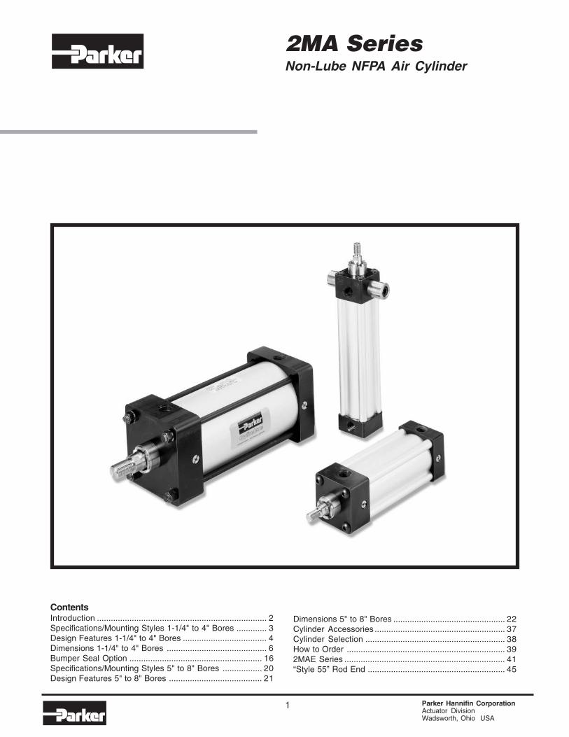
2MA SeriesNon-Lube NFPA Air Cylinder
ContentsIntroduction ......................................................................... 2Specifications/Mounting Styles 1-1/4" to 4" Bores ............. 3Design Features 1-1/4" to 4" Bores .................................... 4Dimensions 1-1/4" to 4" Bores ........................................... 6Bumper Seal Option ......................................................... 16Specifications/Mounting Styles 5" to 8" Bores ................. 20Design Features 5" to 8" Bores ........................................ 21
Dimensions 5" to 8" Bores ................................................ 22Cylinder Accessories ........................................................ 37Cylinder Selection ............................................................ 38How to Order .................................................................... 392MAE Series ..................................................................... 41“Style 55” Rod End ........................................................... 45
Parker Hannifin CorporationActuator DivisionWadsworth, Ohio USA
2
! WARNINGFAILURE OR IMPROPER SELECTION OR IMPROPER USE OF THE PRODUCTS AND/OR SYSTEMS DESCRIBEDHEREIN OR RELATED ITEMS CAN CAUSE DEATH, PERSONAL INJURY AND PROPERTY DAMAGE.
This document and other information from the Company, its subsidiaries and authorized distributors provide productand/or system options for further investigation by users having expertise. It is important that you analyze all aspectsof your application, including consequences of any failure and review the information concerning the product orsystem in the current product catalog. Due to the variety of operating conditions and applications for these productsor systems, the user, through its own analysis and testing, is solely responsible for making the final selection ofthe products and systems and assuring that all performance, safety and warning requirements of the applicationare met.
The products described herein, including without limitation, product features, specifications, designs, availabilityand pricing, are subject to change by the Company and its related companies at any time without notice.
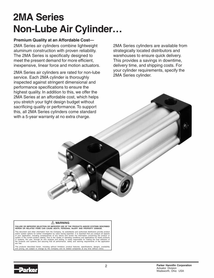
2MA SeriesNon-Lube Air Cylinder…Premium Quality at an Affordable Cost—2MA Series air cylinders combine lightweightaluminum construction with proven reliability.The 2MA Series is specifically designed tomeet the present demand for more efficient,inexpensive, linear force and motion actuators.
2MA Series air cylinders are rated for non-lubeservice. Each 2MA cylinder is thoroughlyinspected against stringent dimensional andperformance specifications to ensure thehighest quality. In addition to this, we offer the2MA Series at an affordable cost, which helpsyou stretch your tight design budget withoutsacrificing quality or performance. To supportthis, all 2MA Series cylinders come standardwith a 5-year warranty at no extra charge.
2MA Series cylinders are available fromstrategically located distributors andwarehouses to ensure quick delivery.This provides a savings in downtime,delivery time, and shipping costs. Foryour cylinder requirements, specify the2MA Series cylinder.
3 Parker Hannifin CorporationActuator DivisionWadsworth, Ohio USA
Air Cylinders2MA Series
Catalog AU03-0900P-2/NA
Standard Specifications, Mounting Styles
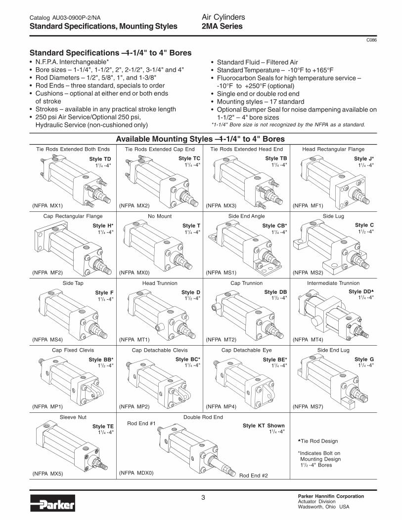
• N.F.P.A. Interchangeable*• Bore sizes – 1-1/4", 1-1/2", 2", 2-1/2", 3-1/4" and 4"• Rod Diameters – 1/2", 5/8", 1", and 1-3/8"• Rod Ends – three standard, specials to order• Cushions – optional at either end or both ends
of stroke• Strokes – available in any practical stroke length• 250 psi Air Service/Optional 250 psi,
Hydraulic Service (non-cushioned only)
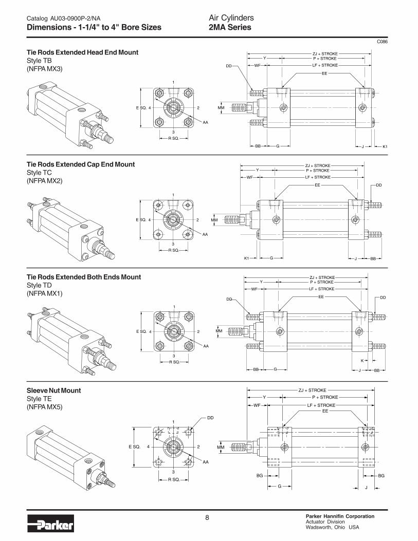
Available Mounting Styles — 1-1/4" to 4" BoresTie Rods Extended Both Ends Tie Rods Extended Cap End Tie Rods Extended Head End Head Rectangular Flange
Cap Rectangular Flange No Mount Side End Angle Side Lug
(NFPA MX0)
Style T11/4 -4"
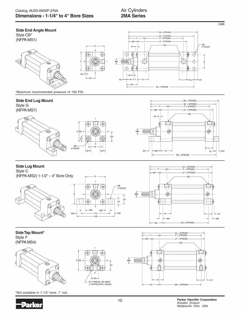
(NFPA MS1)
Style CB*11/4 -4"
(NFPA MS2)
Style C11/2 -4"
(NFPA MF2)
Style H*11/4 -4"
(NFPA MX1)
Style TD11/4 -4"
(NFPA MX2)
Style TC11/4 -4"
(NFPA MX3)
Style TB11/4 -4"
(NFPA MF1)
Style J*11/4 -4"
Side Tap Head Trunnion Cap Trunnion Intermediate Trunnion
(NFPA MT1)
Style D11/2 -4"
(NFPA MT2)
Style DB11/2 -4"
(NFPA MT4)
Style DD▲
11/4 -4"
(NFPA MS4)
Style F11/4 -4"
Cap Fixed Clevis Cap Detachable Clevis Cap Detachable Eye
(NFPA MP2)
Style BC*11/4 -4"
(NFPA MP4)
Style BE*11/4 -4"
(NFPA MS7)
Style G11/4 -4"
(NFPA MP1)
Style BB*11/2 -4"
Double Rod End
Style KT Shown11/4 -4"
Side End Lug
(NFPA MDX0)
*Indicates Bolt on Mounting Design 11/2 -4" Bores
▲Tie Rod Design
Sleeve Nut
(NFPA MX5)
Style TE11/4 -4"
Rod End #2
Rod End #1
Standard Specifications — 1-1/4" to 4" Bores• Standard Fluid – Filtered Air• Standard Temperature – -10°F to +165°F• Fluorocarbon Seals for high temperature service –
-10°F to +250°F (optional)• Single end or double rod end• Mounting styles – 17 standard• Optional Bumper Seal for noise dampening available on
1-1/2" – 4" bore sizes*1-1/4" Bore size is not recognized by the NFPA as a standard.
C086
Air Cylinders2MA Series
Parker Hannifin CorporationActuator DivisionWadsworth, Ohio USA
4
C086
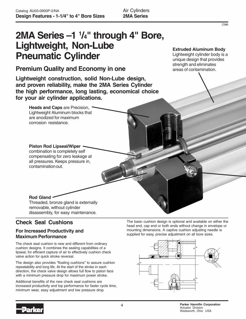
2MA Series – 1 1/4" through 4" Bore,Lightweight, Non-LubePneumatic CylinderPremium Quality and Economy in oneLightweight construction, solid Non-Lube design,and proven reliability, make the 2MA Series Cylinderthe high performance, long lasting, economical choicefor your air cylinder applications.
Check Seal CushionsFor Increased Productivity andMaximum PerformanceThe check seal cushion is new and different from ordinarycushion designs. It combines the sealing capabilities of alipseal, for efficient capture of air to effectively cushion checkvalve action for quick stroke reversal.
The design also provides “floating cushions” to assure cushionrepeatability and long life. At the start of the stroke in eachdirection, the check valve design allows full flow to piston facewith a minimum pressure drop for maximum power stroke.
Additional benefits of the new check seal cushions areincreased productivity and top performance for faster cycle time,minimum wear, easy adjustment and low pressure drop.
The basic cushion design is optional and available on either thehead end, cap end or both ends without change in envelope ormounting dimensions. A captive cushion adjusting needle issupplied for easy, precise adjustment on all bore sizes.
Extruded Aluminum BodyLightweight cylinder body is aunique design that providesstrength and eliminatesareas of contamination.
Heads and Caps are Precision,Lightweight Aluminum blocks thatare anodized for maximumcorrosion resistance.
Piston Rod Lipseal/Wipercombination is completely selfcompensating for zero leakage atall pressures. Keeps pressure in,contamination out.
Rod GlandThreaded, bronze gland is externallyremovable, without cylinderdisassembly, for easy maintenance.
Catalog AU03-0900P-2/NA
Design Features - 1-1/4" to 4" Bore Sizes
Air Cylinders2MA Series
5 Parker Hannifin CorporationActuator DivisionWadsworth, Ohio USA
C086
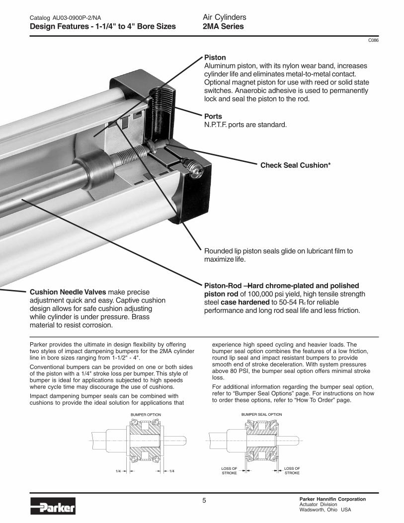
Cushion Needle Valves make preciseadjustment quick and easy. Captive cushiondesign allows for safe cushion adjustingwhile cylinder is under pressure. Brassmaterial to resist corrosion.
Piston-Rod — Hard chrome-plated and polishedpiston rod of 100,000 psi yield, high tensile strengthsteel case hardened to 50-54 Rc for reliableperformance and long rod seal life and less friction.
PortsN.P.T.F. ports are standard.
Check Seal Cushion*
Rounded lip piston seals glide on lubricant film tomaximize life.
PistonAluminum piston, with its nylon wear band, increasescylinder life and eliminates metal-to-metal contact.Optional magnet piston for use with reed or solid stateswitches. Anaerobic adhesive is used to permanentlylock and seal the piston to the rod.
STROKELOSS OF
STROKELOSS OF
1/41/4
BUMPER SEAL OPTIONBUMPER OPTION
Parker provides the ultimate in design flexibility by offeringtwo styles of impact dampening bumpers for the 2MA cylinderline in bore sizes ranging from 1-1/2" - 4".
Conventional bumpers can be provided on one or both sidesof the piston with a 1/4" stroke loss per bumper. This style ofbumper is ideal for applications subjected to high speedswhere cycle time may discourage the use of cushions.
Impact dampening bumper seals can be combined withcushions to provide the ideal solution for applications that
experience high speed cycling and heavier loads. Thebumper seal option combines the features of a low friction,round lip seal and impact resistant bumpers to providesmooth end of stroke deceleration. With system pressuresabove 80 PSI, the bumper seal option offers minimal strokeloss.
For additional information regarding the bumper seal option,refer to “Bumper Seal Options” page. For instructions on howto order these options, refer to “How To Order” page.
Catalog AU03-0900P-2/NA
Design Features - 1-1/4" to 4" Bore Sizes
Air Cylinders2MA Series
Parker Hannifin CorporationActuator DivisionWadsworth, Ohio USA
6
C086
4 2
FB4 HOLES
E
TF
UF
GF J
3
1
MM
LB + STROKE
P + STROKEZJ + STROKE
EE
Y
W
E
K1
R1
4 2
AA
E SQ.
R SQ.
G JK1
3
1
MM
LF + STROKE
P + STROKEZJ + STROKE
WF
EE
Y
GK1 J F
MM
LB + STROKE
P + STROKEZF + STROKE
WF
EE
Y
2 4
FB4 HOLES
R1
E
TF
UF
3
1
E
ZJ + STROKE
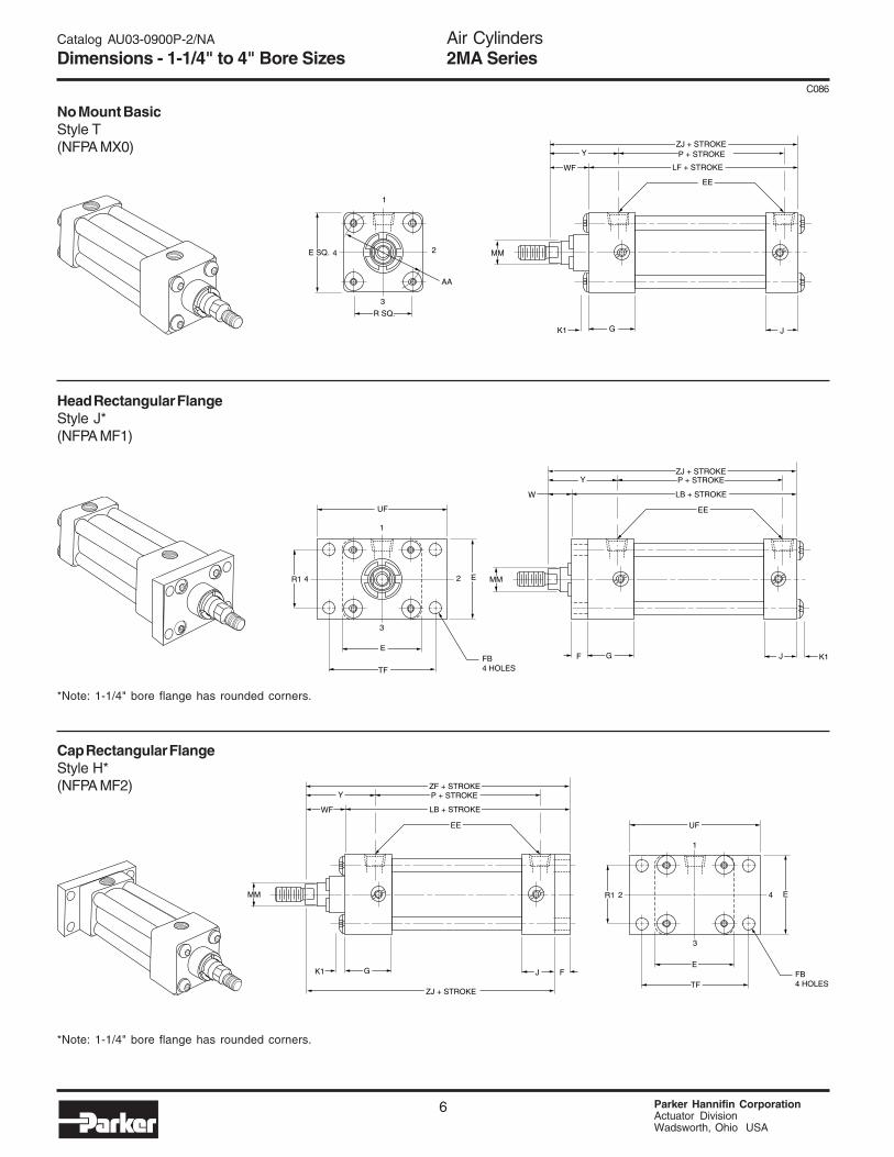
Head Rectangular FlangeStyle J*(NFPA MF1)
Cap Rectangular FlangeStyle H*(NFPA MF2)
No Mount BasicStyle T(NFPA MX0)
*Note: 1-1/4" bore flange has rounded corners.
*Note: 1-1/4" bore flange has rounded corners.
Catalog AU03-0900P-2/NA
Dimensions - 1-1/4" to 4" Bore Sizes
Air Cylinders2MA Series
7 Parker Hannifin CorporationActuator DivisionWadsworth, Ohio USA
C086
Rod Thread Add StrokeStyle Style +.000
Bore Rod Dia. 8 4 & 9 -.002Size No. MM CC KK A B C D LA NA VF W WF Y ZF ZJ
Table 1—Envelope and Mounting DimensionsAdd Stroke
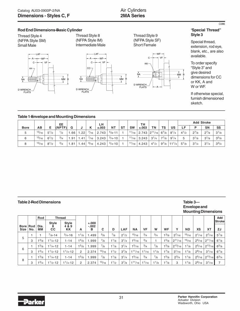
Thread Style 4(NFPA Style SM)Small Male
Thread Style 8(NFPA Style IM)Intermediate Male
Thread Style 9(NFPA Style SF)Short Female
LAF
A WF
C VF
KK
D WRENCHFLATS
NA MM B
LAF
A WF
C VF
CC
D WRENCHFLATS
NA MM B
WF
A
C VF
KK
D WRENCHFLATS
NA MM B
Table 2—Rod Dimensions
Rod Thread Add Stroke
Table 3–Envelope and Mounting Dimensions
* Mounting style CB for 11/4" bore only is furnished with four mounting holes (two each end). Center holes omitted.▲ Mounting style C is not available in 11/4" bore.† Mounting style F for 11/4" bore only is furnished with two mounting holes (one each end).
* Cushion not available head end.▲ Mounting style C is not available in 11/4" bore.
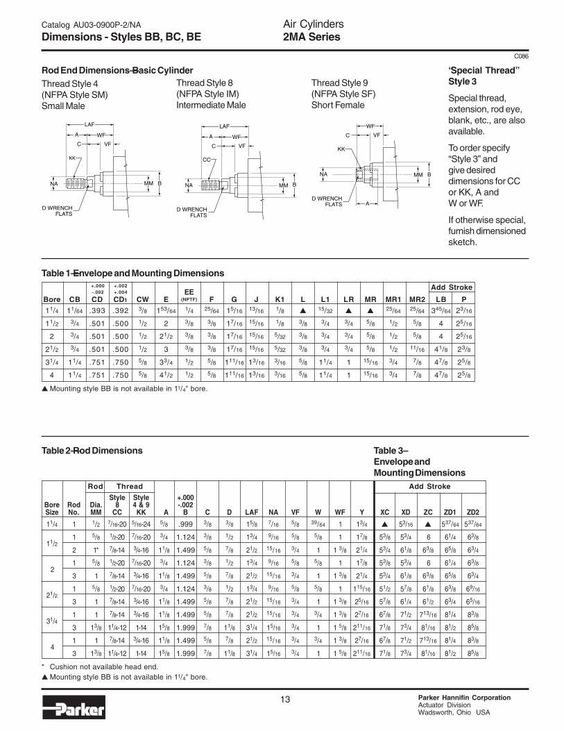
Rod End Dimensions—Basic Cylinder “Special Thread”Style 3
Special thread,extension, rod eye,blank, etc., are alsoavailable.
To order specify“Style 3” andgive desireddimensions for CCor KK, A andW or WF.
If otherwise special,furnish dimensionedsketch.
±.003±.003±.003 (NPTF)
Air Cylinders2MA Series
Parker Hannifin CorporationActuator DivisionWadsworth, Ohio USA
12
C086
Catalog AU03-0900P-2/NA
Dimensions - 1-1/4" to 4" Bore Sizes
2 4
G
XC + STROKE
K1 J F
L3
1
MM
LB + STROKE
P + STROKEZC + STROKE
WF
EE
Y
E SQ.
CW
CB
CW
MR
LR
CD
2 4
G
XD + STROKE
K1 J F
L13
1
MM
LB + STROKE
P + STROKEZD1 + STROKE
WF
EE
Y
E SQ.
CW
CB
CW
MR 1
CD
2 4
G
XD + STROKE
K1 J F
L13
1
MM
LB + STROKE
P + STROKEZD2 + STROKE
WF
EE
Y
E SQ.
CB
MR2
CD1
Cap Fixed Clevis MountStyle BB(NFPA MP1) 1-1/2" – 4" Bore Only
Cap Detachable Clevis MountStyle BC(NFPA MP2)
Cap Detachable Eye MountStyle BE(NFPA MP4)
For maximum swivel angle with rear mounting plate for “BB” mounting, see 2MA Series cylinder accessories.
1-1/4" Bore
1-1/4" Bore
1-1/2" – 4" Bore
1-1/2" – 4" Bore
Air Cylinders2MA Series
13 Parker Hannifin CorporationActuator DivisionWadsworth, Ohio USA
C086
Catalog AU03-0900P-2/NA
Dimensions - Styles BB, BC, BE
EEBore CB CD CD1 CW E F G J K1 L L1 LR MR MR1 MR2 LB P
Table 1—Envelope and Mounting DimensionsAdd Stroke Style
MT4Minimum
Stroke
+.000
-.001(NPTF)
Thread Style 4(NFPA Style SM)Small Male
Thread Style 8(NFPA Style IM)Intermediate Male
Thread Style 9(NFPA Style SF)Short Female
LAF
A WF
C VF
KK
D WRENCHFLATS
NA MM B
LAF
A WF
C VF
CC
D WRENCHFLATS
NA MM B
WF
A
C VF
KK
D WRENCHFLATS
NA MM B
Table 2—Rod Dimensions
Rod Thread
Table 3–Envelope andMounting Dimensions
Add Stroke
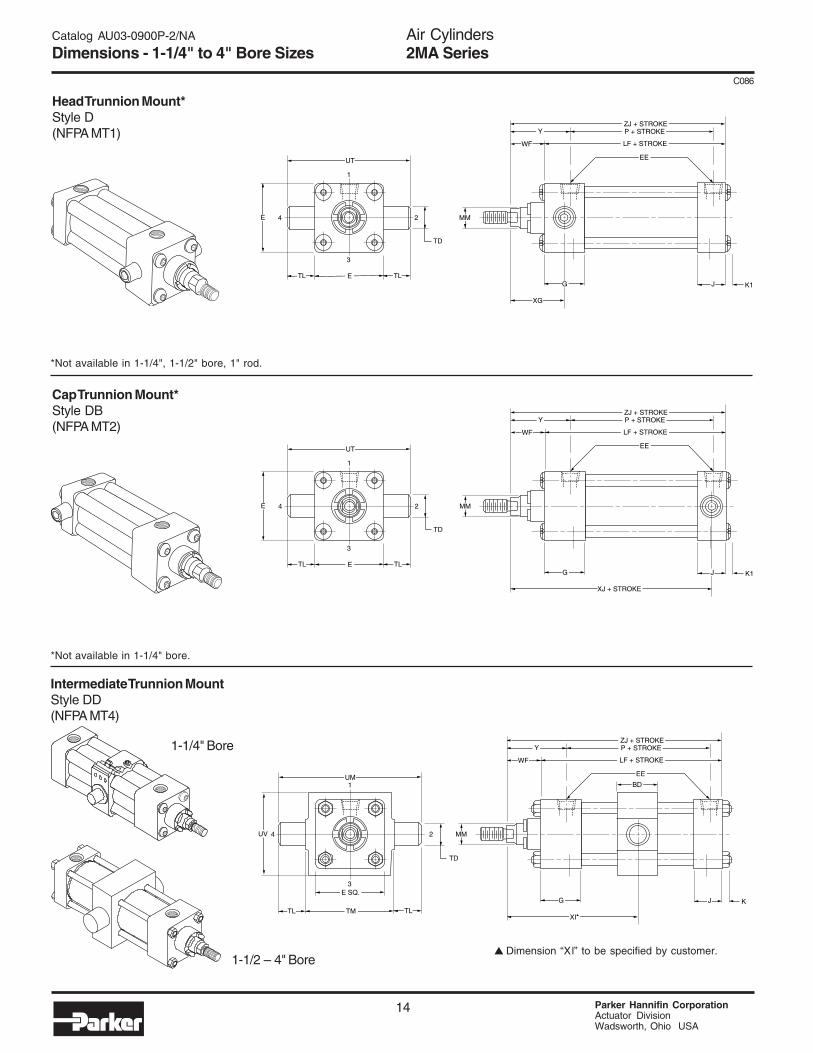
* Cushion not available head end.▲ Dimension “Xl” to be specified by customer.■ Mounting styles D and DB are not available in 11/4" bore.
■ Mounting styles D and DB are not available in 11/4" bore.
▲▲▲▲▲Min.
“Special Thread”Style 3
Special thread,extension, rod eye,blank, etc., are alsoavailable.
To order specify“Style 3” andgive desireddimensions for CCor KK, A andW or WF.
If otherwise special,furnish dimensionedsketch.
Air Cylinders2MA Series
Parker Hannifin CorporationActuator DivisionWadsworth, Ohio USA
16
C086
Catalog AU03-0900P-2/NA
Bumper Seal Option
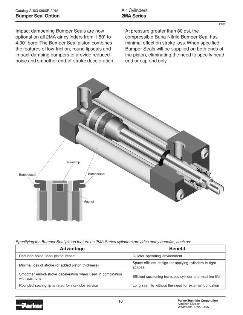
Impact dampening Bumper Seals are nowoptional on all 2MA air cylinders from 1.50" to4.00" bore. The Bumper Seal piston combinesthe features of low-friction, round lipseals andimpact-damping bumpers to provide reducednoise and smoother end-of-stroke deceleration.
At pressure greater than 80 psi, thecompressible Buna Nitrile Bumper Seal hasminimal effect on stroke loss. When specified,Bumper Seals will be supplied on both ends ofthe piston, eliminating the need to specify headend or cap end only.
Specifying the Bumper Seal piston feature on 2MA Series cylinders provides many benefits, such as:
AdvantageReduced noise upon piston impact
Minimal loss of stroke (or added piston thickness)
Smoother end-of-stroke deceleration when used in combinationwith cushions
Rounded sealing lip is rated for non-lube service
BenefitQuieter operating environment
Space-efficient design for applying cylinders in tightspaces
Efficient cushioning increases cylinder and machine life
Long seal life without the need for external lubrication
Magnet
BumpersealBumperseal
Wearstrip
Air Cylinders2MA Series
17 Parker Hannifin CorporationActuator DivisionWadsworth, Ohio USA
C086
Catalog AU03-0900P-2/NA
Bumper Seal Option
Summary ofAccelerometerTest Results
Bore Piston Cushioning Efficiency Cushioning TimeSize Type (Maximum G's of (Ms)
deceleration force created)
1.50"
2.00"
2.50"
Standard Piston 13.4 22Bumper Seal Piston 5.1 22Standard Piston 12.6 33Bumper Seal Piston 7.8 26Standard Piston 12.2 36Bumper Seal Piston 5.2 24
Bumper Seals Reduce Noise
The special profile of the Bumper Sealprevents the piston from banging intothe end cap at the end of stroke.Independent testing shows that theBumper Seal, when combined withcushions, will absorb the final pistoninertia and reduce the stroke noise byas much as 20 dB. The Sound LevelComparison graph illustrates the noise-reducing effects of the Bumper Sealpiston when combined with cushions.
Impact noise was recorded at a distance of3 feet from the front of the cylinder, inside asemi-anechoic chamber. Cylinders wereoperating at 95 psi.
Bumper Seals have Minimum Effect on Stroke Length
The accompanying chart depicts typical amountsof overall stroke loss incurred at various systempressures. The amount of stroke loss may varyslightly due to design tolerances of: seal size,variance in seal durometer, and compression setassociated with cylinder wear. To determine thestroke loss at either end of the cylinder, divide thevalues by two.
Typical Overall Loss by Bore Size (in.)Pressure 1.50" 2.00" 2.50" 3.25" 4.00"
All dimensions are in inches and apply to standard rod sizes only. For alternate rodsizes, determine all envelope dimensions (within LD dim.) as described above and thenuse appropriate rod end dimensions for proper rod size from single rod cylinder.
RodDia.
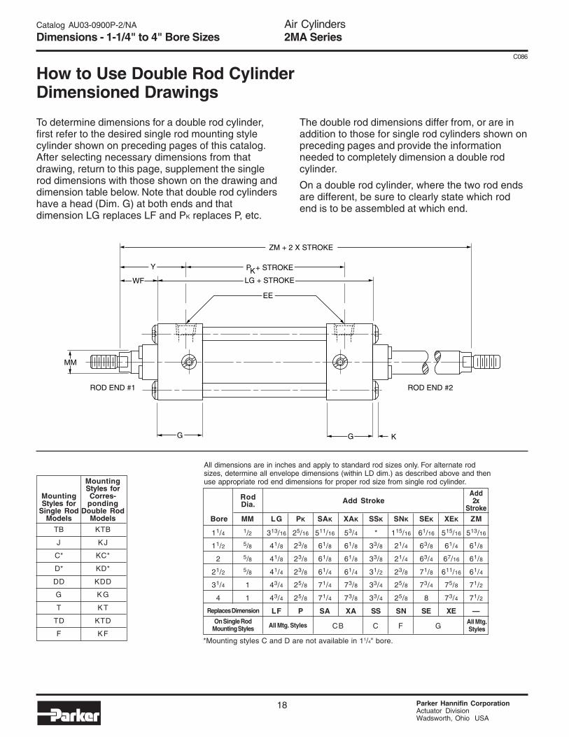
How to Use Double Rod CylinderDimensioned Drawings
To determine dimensions for a double rod cylinder,first refer to the desired single rod mounting stylecylinder shown on preceding pages of this catalog.After selecting necessary dimensions from thatdrawing, return to this page, supplement the singlerod dimensions with those shown on the drawing anddimension table below. Note that double rod cylindershave a head (Dim. G) at both ends and thatdimension LG replaces LF and PK replaces P, etc.
G G K
MM
LG + STROKE
P + STROKE
ZM + 2 X STROKE
ROD END #1 ROD END #2
WF
EE
Y K
Add2x
Stroke
CB C F G
Add Stroke
*Mounting styles C and D are not available in 11/4" bore.
The double rod dimensions differ from, or are inaddition to those for single rod cylinders shown onpreceding pages and provide the informationneeded to completely dimension a double rodcylinder.
On a double rod cylinder, where the two rod endsare different, be sure to clearly state which rodend is to be assembled at which end.
MountingStyles forCorres-
pondingDouble Rod
Models
KTB
KJ
KC*
KD*
KDD
K G
KT
KTD
KF
MountingStyles for
Single RodModels
TB
J
C*
D*
DD
G
T
TD
F
Replaces Dimension
On Single RodMounting Styles All Mtg. Styles All Mtg.
Styles
Air Cylinders2MA Series
19 Parker Hannifin CorporationActuator DivisionWadsworth, Ohio USA
C086
Catalog AU03-0900P-2/NA
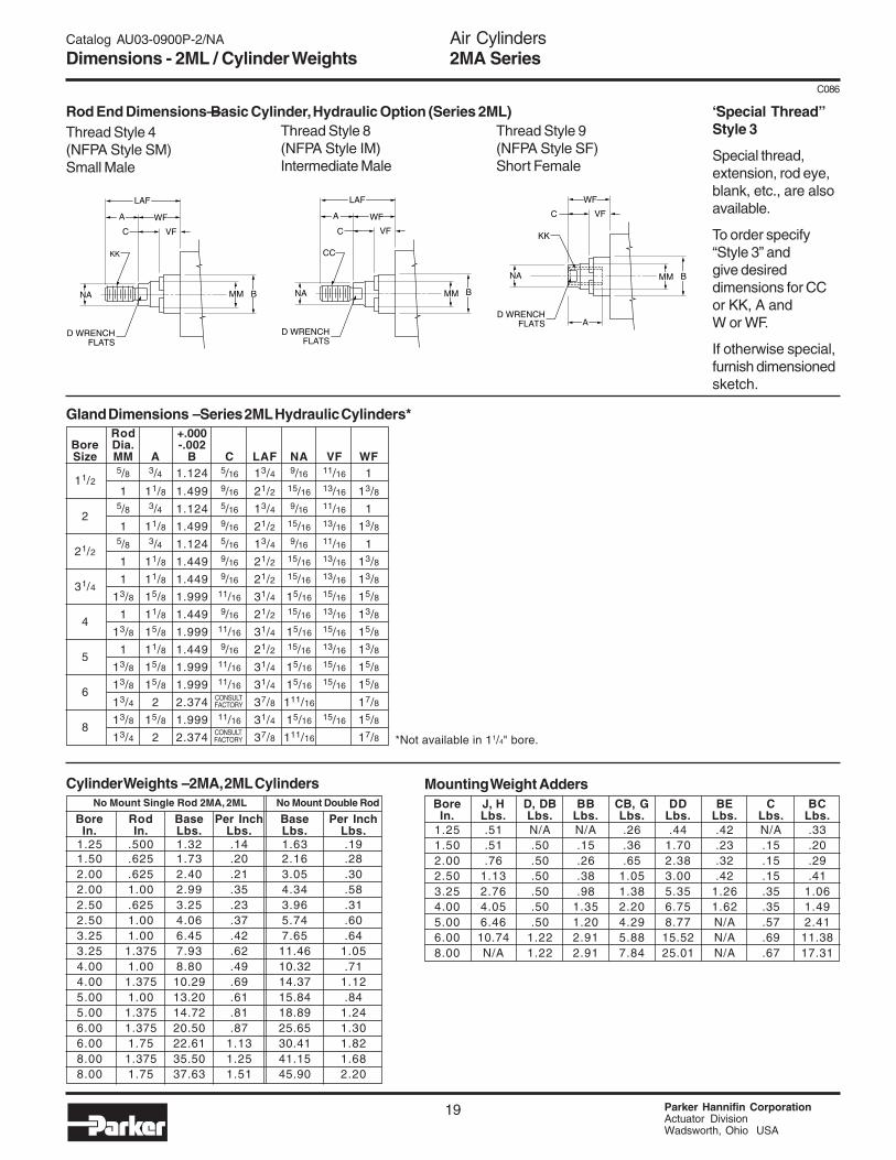
Dimensions - 2ML / Cylinder Weights
Rod End Dimensions—Basic Cylinder, Hydraulic Option (Series 2ML)Thread Style 4(NFPA Style SM)Small Male
Thread Style 8(NFPA Style IM)Intermediate Male
Thread Style 9(NFPA Style SF)Short Female
LAF
A WF
C VF
KK
D WRENCHFLATS
NA MM B
LAF
A WF
C VF
CC
D WRENCHFLATS
NA MM B
WF
A
C VF
KK
D WRENCHFLATS
NA MM B
Gland Dimensions – Series 2ML Hydraulic Cylinders*
*Not available in 11/4" bore.
Rod +.000Bore Dia. -.002Size MM A B C LAF NA VF WF
11/25/8 3/4 1.124 5/16 13/4 9/16 11/16 1
1 11/8 1.499 9/16 21/2 15/16 13/16 13/8
25/8 3/4 1.124 5/16 13/4 9/16 11/16 1
1 11/8 1.499 9/16 21/2 15/16 13/16 13/8
21/25/8 3/4 1.124 5/16 13/4 9/16 11/16 1
1 11/8 1.449 9/16 21/2 15/16 13/16 13/8
31/41 11/8 1.449 9/16 21/2 15/16 13/16 13/8
13/8 15/8 1.999 11/16 31/4 15/16 15/16 15/8
41 11/8 1.449 9/16 21/2 15/16 13/16 13/8
13/8 15/8 1.999 11/16 31/4 15/16 15/16 15/8
51 11/8 1.449 9/16 21/2 15/16 13/16 13/8
13/8 15/8 1.999 11/16 31/4 15/16 15/16 15/8
613/8 15/8 1.999 11/16 31/4 15/16 15/16 15/8
13/4 2 2.374 37/8 111/16 17/8
813/8 15/8 1.999 11/16 31/4 15/16 15/16 15/8
13/4 2 2.374 37/8 111/16 17/8
CONSULTFACTORY
CONSULTFACTORY
Bore J, H D, DB BB CB, G DD BE C BCIn. Lbs. Lbs. Lbs. Lbs. Lbs. Lbs. Lbs. Lbs.
Special thread,extension, rod eye,blank, etc., are alsoavailable.
To order specify“Style 3” andgive desireddimensions for CCor KK, A andW or WF.
If otherwise special,furnish dimensionedsketch.
Air Cylinders2MA Series
Parker Hannifin CorporationActuator DivisionWadsworth, Ohio USA
20
C086
Catalog AU03-0900P-2/NA
Standard Specifications, Mounting Styles
Standard Specifications — 5" to 8" Bores• N.F.P.A. Interchangeable• Bore sizes – 5", 6" and 8"• Rod Diameters – 1", 1-3/8", and 1-3/4"• Rod Ends – three standard, specials to order.• Cushions – optional at either end or both ends
of stroke• Strokes – available in any practical stroke length.• 250 psi Air Service• 250 psi Hydraulic Service (non-cushioned only)
Available Mounting Styles — 5" to 8" BoresTie Rods Extended Both Ends Tie Rods Extended Cap End Tie Rods Extended Head End Head Rectangular Flange
Cap Rectangular Flange No Mount Side End Angle Side Lug
(NFPA MX0)
Style T5"-8"
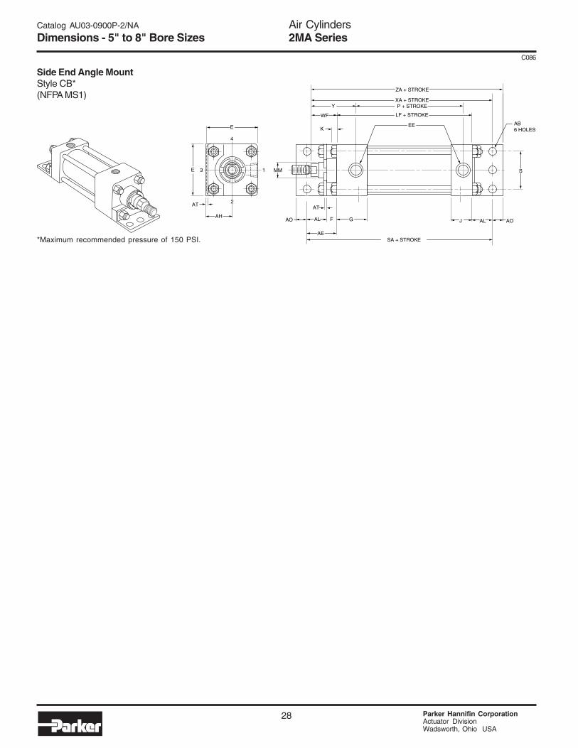
(NFPA MS1)
Style CB5"-8"
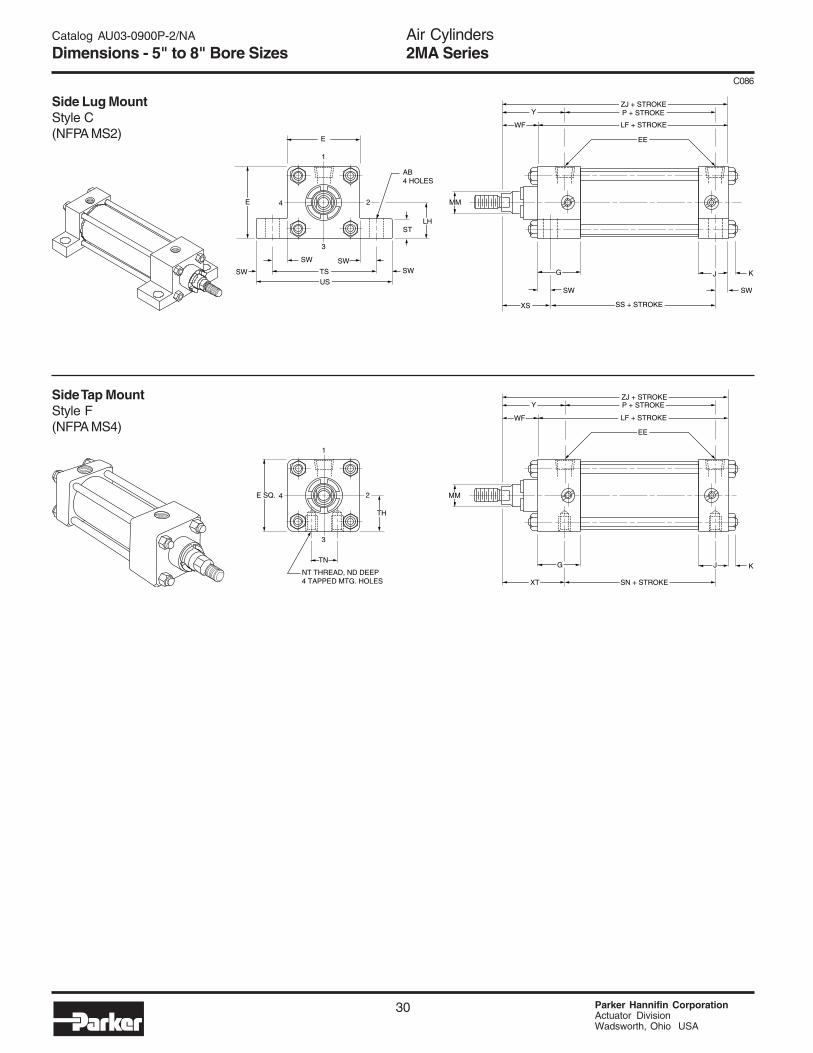
(NFPA MS2)
Style C5"-8"
(NFPA MF2)
Style H5"-6"
(NFPA MX1)
Style TD5"-8"
(NFPA MX2)
Style TC5"-8"
(NFPA MX3)
Style TB5"-8"
(NFPA MF1)
Style J5"-6"
Side Tap Head Trunnion Cap Trunnion Intermediate Trunnion
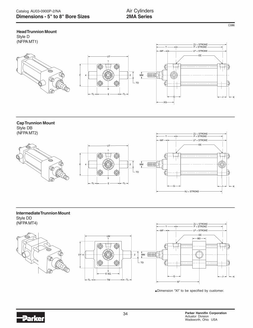
(NFPA MT1)
Style D5"-8"
(NFPA MT2)
Style DB5"-8"
(NFPA MT4)
Style DD5"-8"
(NFPA MS4)
Style F5"-8"
Cap Fixed Clevis Cap Detachable Clevis Head Square
(NFPA MP2)
Style BC5"-8"
(NFPA ME3)
Style JB8"
(NFPA MP1)
Style BB5"-8"
Double Rod End
(NFPA ME4)
Style HB8"
Cap Square
Style KT Shown5"-8"
(NFPA MDX0)
Sleeve Nut
(NFPA MX5)
Style TE5"-8"
Cap Detachable Eye
Style BE5"-6"ROD END
#1
• Standard Fluid – Filtered Air• Standard Temperature – -10°F to +165°F• Fluorocarbon Seals for high temperature service –
-10°F to +250°F (optional)• Single end or double end• Mounting styles – 18 standard
Air Cylinders2MA Series
21 Parker Hannifin CorporationActuator DivisionWadsworth, Ohio USA
C086
Catalog AU03-0900P-2/NA
Design Features and Materials
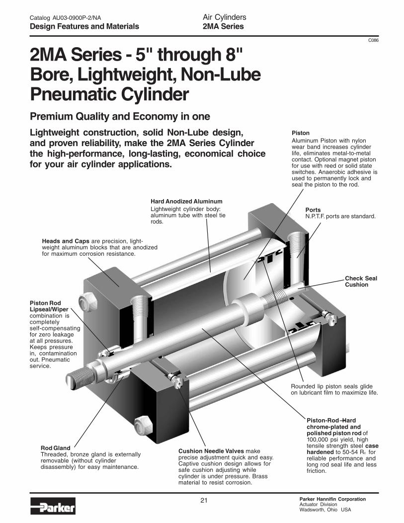
2MA Series - 5" through 8"Bore, Lightweight, Non-LubePneumatic CylinderPremium Quality and Economy in oneLightweight construction, solid Non-Lube design,and proven reliability, make the 2MA Series Cylinderthe high-performance, long-lasting, economical choicefor your air cylinder applications.
Hard Anodized AluminumLightweight cylinder body:aluminum tube with steel tierods.
Check SealCushion
PortsN.P.T.F. ports are standard.
Rounded lip piston seals glideon lubricant film to maximize life.
Piston-Rod —Hardchrome-plated andpolished piston rod of100,000 psi yield, hightensile strength steel casehardened to 50-54 Rc forreliable performance andlong rod seal life and lessfriction.
Cushion Needle Valves makeprecise adjustment quick and easy.Captive cushion design allows forsafe cushion adjusting whilecylinder is under pressure. Brassmaterial to resist corrosion.
PistonAluminum Piston with nylonwear band increases cylinderlife, eliminates metal-to-metalcontact. Optional magnet pistonfor use with reed or solid stateswitches. Anaerobic adhesive isused to permanently lock andseal the piston to the rod.
Rod GlandThreaded, bronze gland is externallyremovable (without cylinderdisassembly) for easy maintenance.
Piston RodLipseal/Wipercombination iscompletelyself-compensatingfor zero leakageat all pressures.Keeps pressurein, contaminationout. Pneumaticservice.
Heads and Caps are precision, light-weight aluminum blocks that are anodizedfor maximum corrosion resistance.
Air Cylinders2MA Series
Parker Hannifin CorporationActuator DivisionWadsworth, Ohio USA
22
C086
Catalog AU03-0900P-2/NA
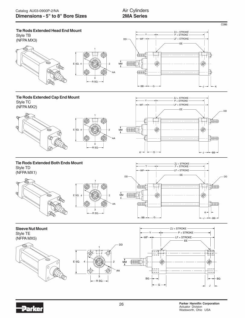
Dimensions - 5" to 8" Bore Sizes
No Mount (5" and 8" Bore Sizes)Style T(NFPA MX0)
Head Rectangular Flange Mount (5" and 6" Bore Sizes)Style J(NFPA MF1)
Cap Rectangular Flange Mount (5" and 6" Bore Sizes)Style H(NFPA MF2)
4 2
AA
E SQ.
R SQ.
G J K
3
1
MM
LF + STROKE
P + STROKEZJ + STROKE
WF
EE
Y
4 2
FB4 HOLES
E
TF
UF
GF J K
3
1
MM
LB + STROKE
P + STROKEZJ + STROKE
EE
Y
W
ER
GK J F
MM
LB + STROKE
P + STROKEZF + STROKE
WF
EE
Y
2 4
FB4 HOLES
R
E
TF
UF
3
1
E
ZJ + STROKE
Air Cylinders2MA Series
23 Parker Hannifin CorporationActuator DivisionWadsworth, Ohio USA
C086
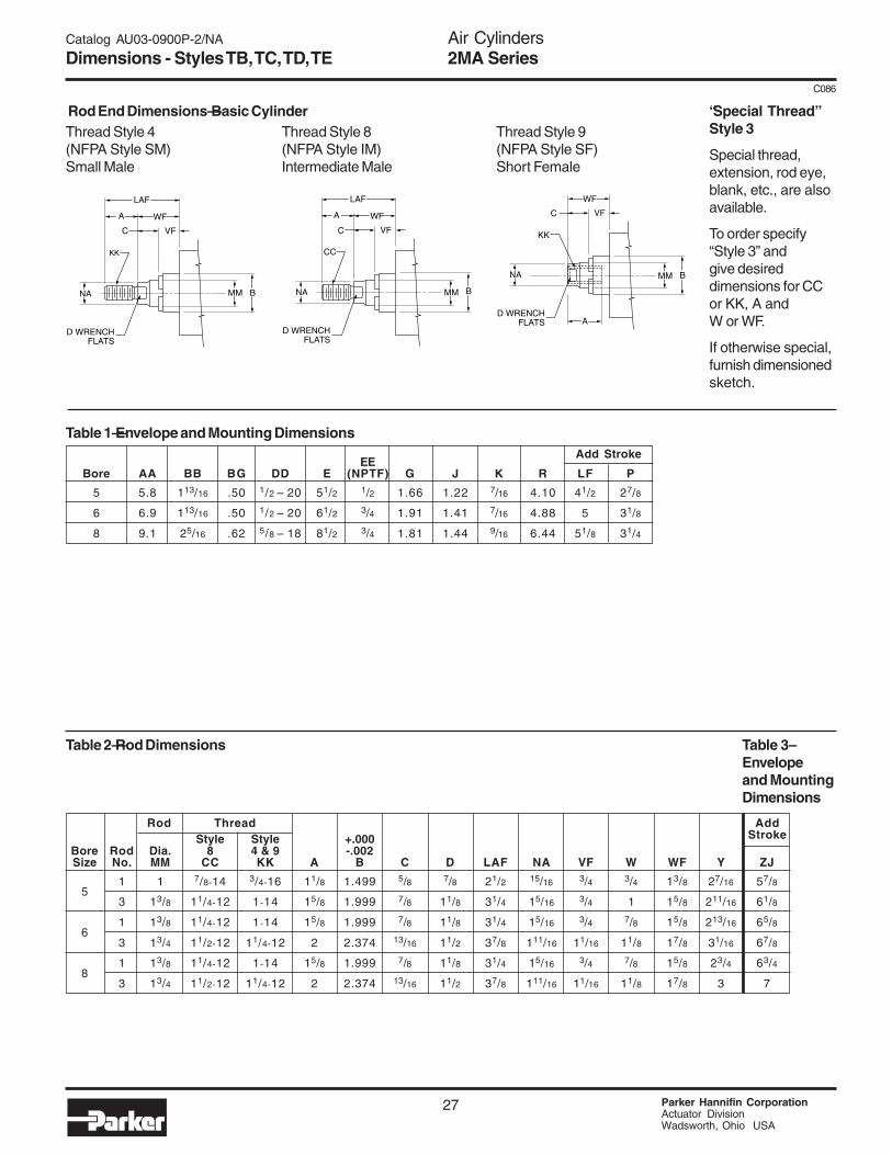
Catalog AU03-0900P-2/NA
Dimensions - Styles T, J, H
Rod Thread Add StrokeStyle Style +.000
Bore Rod Dia. 8 4 & 9 -.002Size No. MM CC KK A B C D LA NA VF W WF Y ZF ZJ
Special thread,extension, rod eye,blank, etc., are alsoavailable.
To order specify“Style 3” andgive desireddimensions for CCor KK, A andW or WF.
If otherwise special,furnish dimensionedsketch.
Air Cylinders2MA Series
Parker Hannifin CorporationActuator DivisionWadsworth, Ohio USA
36
C086
Catalog AU03-0900P-2/NA
Dimensions - 5" to 8" Bore Sizes
How to Use Double Rod CylinderDimensioned DrawingsTo determine dimensions for a double rod cylinder,first refer to the desired single rod mounting stylecylinder shown on preceding pages of this catalog.After selecting necessary dimensions from thatdrawing, return to this page and supplement thesingle rod dimensions with those shown on thedrawing and dimension table below. Note thatdouble rod cylinders have a head (Dim. G) at bothends and that dimension LG replaces LF and PK
G G K
MM
LG + STROKE
P + STROKE
ZM + 2 X STROKE
WF
EE
Y K
ROD END #1 ROD END #2
replaces P, etc. The double rod dimensions differfrom, or are in addition to those for single rodcylinders shown on preceding pages and providethe information needed to completely dimension adouble rod cylinder.
On a double rod cylinder where the two rod endsare different, be sure to clearly state which rod endis to be assembled and at which end.
All dimensions are in inches and apply to standard rod sizes only. Foralternate rod sizes, determine all envelope dimensions (within LD dim.) asdescribed above and then use appropriate rod end dimensions for properrod size from single rod cylinder.
Air Cylinders2MA Series
37 Parker Hannifin CorporationActuator DivisionWadsworth, Ohio USA
C086
Catalog AU03-0900P-2/NA
Cylinder Accessories
Symbol 0856640044 0856640050 0856640075 0856640100 0856640138 0856640175
CD 7/16 1/2 3/4 1 13/8 13/4
CL 15/16 17/8 25/8 31/8 41/8 53/16
ShearCap. 6600 8600 19300 34300 65000 105200Lbs.
A¡
CD
CL
CD
CBCACD
CD
CD
+.004+.002ER
A
KK
FULLTHREAD
THREAD
CD+.004+.002
ERCW CWCB
ACE
KK THREAD
TABLE A TABLE B TABLE C
Mating Parts Mating Parts Mounting PlateRodEnd Female For Mtg. For Mtg.
Cylinder AccessoriesRod end accessories can be selected by cylinder rod end thread size from Table A & Bbelow. Mating parts for rod end accessories are listed just to the right of the knuckle orclevis selected. Mounting plates for style MP1 & MP4 cylinder mounts are selected bybore size from Table C.
Note: Pivot Pin must be ordered separately forsingle lug pivot mounting.
Pivot Pin+.001 -.002
*Includes Pivot Pin
Bore 11/4 11/2 2 21/2 31/4 4 5 6 8
Angle A 55 52 43 29 50 49 45 42 42
Female Rod Clevis Rod Eye Knuckle
Clevis Bracket Mounting Plate & Eye Bracket
Air Cylinders2MA Series
Parker Hannifin CorporationActuator DivisionWadsworth, Ohio USA
38
C086
Catalog AU03-0900P-2/NA
Cylinder Selection
How to Select a CylinderParker cylinders are available based on air or hydraulic operating pressure. The many styles, sizes and optional featuresavailable assure that your application requirements are met precisely. To select a Parker cylinder, follow these simplesteps:
Step 1 - Determine the correct cylinder bore size necessary to achieve required force using the available operatingpressure.
Step 2 - Determine the series cylinder to use, based on operating pressure.
Step 3 - Turn to the appropriate cylinder selection section. Select the mounting style that fits your installation needs.Determine the bore and rod sizes available for the model you select. Then complete model selection.
- Choose a rod end style and the desired rod end accessories.
- Size the cylinder to meet your application requirements.
Step 4 - Consider the following conditions which may require further modifications to the cylinder you have selected.See Table of Contents for location of additional information on each subject.
Table C – Mounting Styles
* 8" bore only.**** Mounting styles can be ordered assembled to the cylinder or as a basic (T) no-mount cylinder with a bolt on mounting kit as a separate
item (1-1/2 to 4" only).† For cylinders with intermediate trunnion mounting (style DD) specify distance between the piston rod end reference point and the
centerline of the trunnion pin (dimension "XI").▲ Not available on 1-1/4" Bore.
T No Mount JB*▲ Head Square DB▲ Cap Trunnion
TD Tie Rods Extended Both Ends HB*▲ Cap Square BB▲ Cap Fixed ClevisTC Tie Rods Extended Cap End CB**** Side End Angle BC Cap Detachable Clevis
TB Tie Rods Extended Head End C▲ Side Lug DD† Intermediate Trunnion
TE Sleeve Nut F▲ Side Tap BE**** Cap Detachable Eye
J**** Head Rectangular Flange G Side End LugH**** Cap Rectangular Flange D▲ Head Trunnion
ApplicationCondition Check the Following
Quick Starts or Stops Confirm that determined thrust is sufficient to accelerate or decelerate cylinder and load withinprescribed distance. Optional cushions should be used to reduce shock during deceleration, checkthat peak pressures will be within tolerable limits.
Long Push Stroke Check whether stop tube is required to prevent excessive bearing loads and wear.
High-column Loading Determine if standard size piston rod is strong enough to accommodate intended load.Long Push Stroke
Long Horizontal Stroke Determine if standard size piston rod is strong enough to accommodate intended load.
High Operating For temperatures between 165°F and 250°F use 2MA cylinder with high temperature seals.Temperatures
Options and - Adjustable CushionsModifications - Piston Bumper Seals (1-1/2" through 4")
- Adjustable Switches- Linear Position Sensing- Piston Bumpers (1-1/2" through 8")- Port and Cushion Adjust Relocation
- Stop Tube- Mixed Mountings- Rod End Modifications- Double Rod End- Multiple Ports
Air Cylinders2MA Series
39 Parker Hannifin CorporationActuator DivisionWadsworth, Ohio USA
C086
Catalog AU03-0900P-2/NA
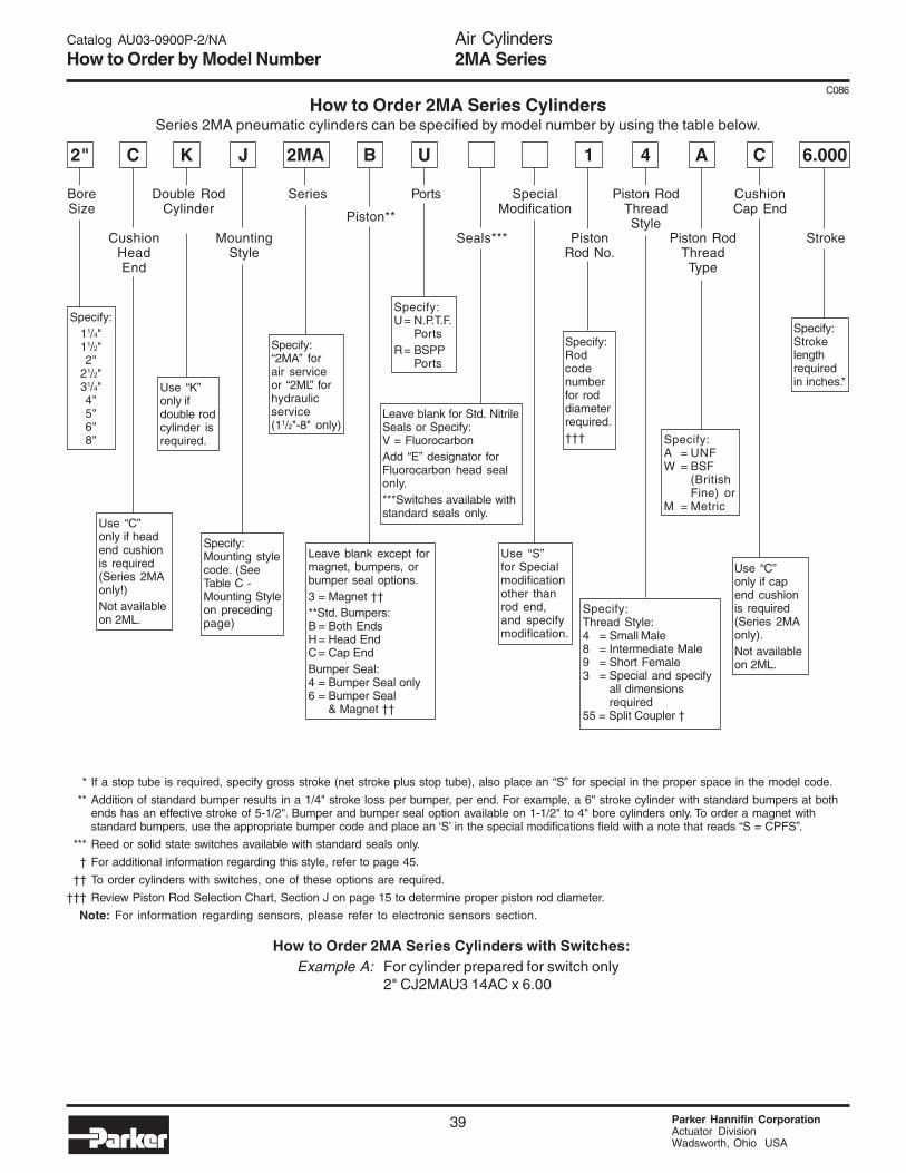
How to Order by Model Number
How to Order 2MA Series CylindersSeries 2MA pneumatic cylinders can be specified by model number by using the table below.
How to Order 2MA Series Cylinders with Switches:Example A: For cylinder prepared for switch only
2" CJ2MAU3 14AC x 6.00
2MA
BoreSize
C
CushionHeadEnd
K J
MountingStyle
B
Piston**
U 1
PistonRod No.
4 A
Piston RodThreadType
C 6.000
Stroke
Double RodCylinder
Series Ports SpecialModification
Piston RodThreadStyle
CushionCap End
2"
Seals***
Specify:11/4"11/2"2"
21/2"31/4"4"5"6"8"
Use “C”only if headend cushionis required(Series 2MAonly!)Not availableon 2ML.
Use “K”only ifdouble rodcylinder isrequired.
Specify:Mounting stylecode. (SeeTable C -Mounting Styleon precedingpage)
Leave blank except formagnet, bumpers, orbumper seal options.3 = Magnet ††**Std. Bumpers:B = Both EndsH= Head EndC= Cap EndBumper Seal:4 = Bumper Seal only6 = Bumper Seal
& Magnet ††
Specify:Strokelengthrequiredin inches.*
Use “C”only if capend cushionis required(Series 2MAonly).Not availableon 2ML.
Specify:A = UNFW = BSF
(BritishFine) or
M = Metric
Specify:Thread Style:4 = Small Male8 = Intermediate Male9 = Short Female3 = Special and specify
all dimensionsrequired
55 = Split Coupler †
Specify:Rodcodenumberfor roddiameterrequired.†††
Use “S”for Specialmodificationother thanrod end,and specifymodification.
Leave blank for Std. NitrileSeals or Specify:V = FluorocarbonAdd “E” designator forFluorocarbon head sealonly.***Switches available withstandard seals only.
Specify:U= N.P.T.F.
PortsR= BSPP
Ports
* If a stop tube is required, specify gross stroke (net stroke plus stop tube), also place an “S” for special in the proper space in the model code.
** Addition of standard bumper results in a 1/4" stroke loss per bumper, per end. For example, a 6" stroke cylinder with standard bumpers at bothends has an effective stroke of 5-1/2". Bumper and bumper seal option available on 1-1/2" to 4" bore cylinders only. To order a magnet withstandard bumpers, use the appropriate bumper code and place an ‘S’ in the special modifications field with a note that reads “S = CPFS”.
*** Reed or solid state switches available with standard seals only.
† For additional information regarding this style, refer to page 45.
†† To order cylinders with switches, one of these options are required.
††† Review Piston Rod Selection Chart, Section J on page 15 to determine proper piston rod diameter.
Note: For information regarding sensors, please refer to electronic sensors section.
Air Cylinders2MA Series
Parker Hannifin CorporationActuator DivisionWadsworth, OH USA
40
Catalog AU03-0900P-2/NA
Notes
NOTES
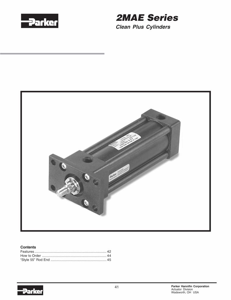
41 Parker Hannifin CorporationActuator DivisionWadsworth, OH USA
2MAE SeriesClean Plus Cylinders
ContentsFeatures ............................................................................ 42How to Order .................................................................... 44“Style 55” Rod End ........................................................... 45
Parker Hannifin CorporationActuator DivisionWadsworth, Ohio USA
42
Heads and Caps are Precision,Lightweight Aluminum blocks thatare Lectrofluor® coated formaximum corrosion resistance.
Piston rod lipseal/wiper combinationis completely self compensating forzero leakage at all pressures. Keepspressure in, contamination out.Pneumatic service.
Rod GlandThreaded, bronze gland isexternally removable withoutcylinder disassembly for easymaintenance.
Hard AnodizedLECTROFLUOR® * CoatedAluminumLightweight cylinder body:unique design providesstrength, eliminates areas ofcontaminant collection andallows for effectivewashdown.
A group of high-technology coatings, each with uniqueproperties that include superior corrosion and chemicalresistance, USDA approvals and FDA compliance.
The LECTROFLUOR® series of high-technologypolymer-based coatings was developed to actas a protective surface on non-ferrous metals.They provide superior resistance to corrosionand chemical attack in hostile environment
applications. In addition, LECTROFLUOR®
coatings carry USDA approval/FDA compliance foruse in food, pharmaceutical or medicalapplications.
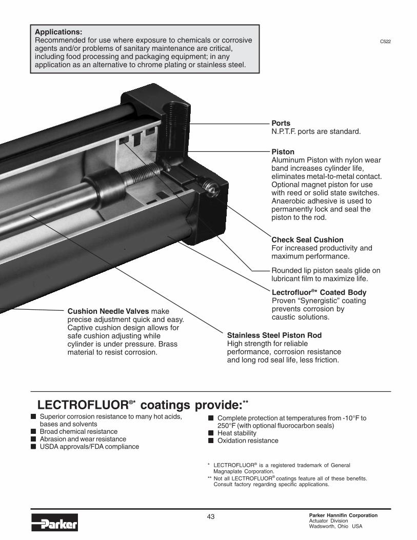
2MAE Series Clean Plus11/2" through 4" Bore Lightweight,Non-Lube, Anti CorrosionPneumatic Cylinder.Premium Quality and Economy in one.
Lightweight construction and solid Non-Lube design withproven reliability make the 2MAE Series Clean PlusCylinder the high performance, long lasting, economicalchoice for your air cylinder applications.
43 Parker Hannifin CorporationActuator DivisionWadsworth, Ohio USA
PistonAluminum Piston with nylon wearband increases cylinder life,eliminates metal-to-metal contact.Optional magnet piston for usewith reed or solid state switches.Anaerobic adhesive is used topermanently lock and seal thepiston to the rod.
PortsN.P.T.F. ports are standard.
Check Seal CushionFor increased productivity andmaximum performance.
Rounded lip piston seals glide onlubricant film to maximize life.
Stainless Steel Piston RodHigh strength for reliableperformance, corrosion resistanceand long rod seal life, less friction.
LECTROFLUOR® * coatings provide:**
■■■■■ Superior corrosion resistance to many hot acids,bases and solvents
■■■■■ Broad chemical resistance■■■■■ Abrasion and wear resistance■■■■■ USDA approvals/FDA compliance
Applications:Recommended for use where exposure to chemicals or corrosiveagents and/or problems of sanitary maintenance are critical,including food processing and packaging equipment; in anyapplication as an alternative to chrome plating or stainless steel.
■■■■■ Complete protection at temperatures from -10°F to250°F (with optional fluorocarbon seals)
■■■■■ Heat stability■■■■■ Oxidation resistance
* LECTROFLUOR® is a registered trademark of GeneralMagnaplate Corporation.
** Not all LECTROFLUOR® coatings feature all of these benefits.Consult factory regarding specific applications.
Cushion Needle Valves makeprecise adjustment quick and easy.Captive cushion design allows forsafe cushion adjusting whilecylinder is under pressure. Brassmaterial to resist corrosion.
C522
Air Cylinders2MAE Series
Parker Hannifin CorporationActuator DivisionWadsworth, OH USA
44
C522
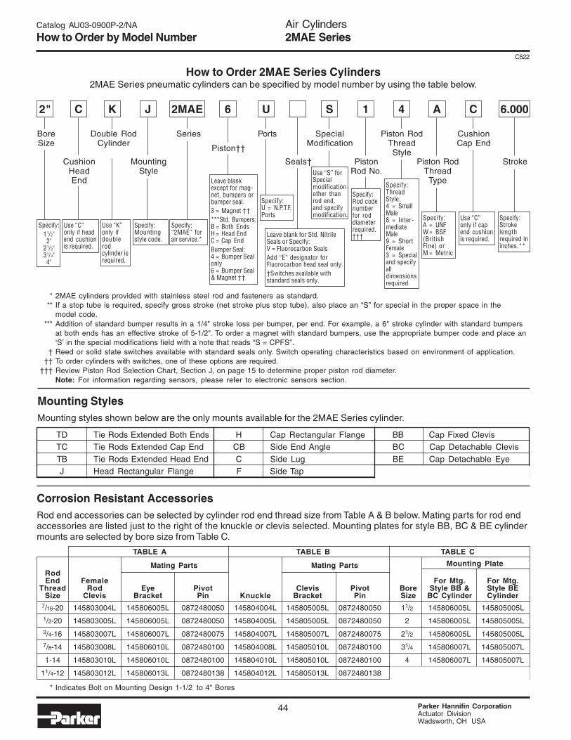
Catalog AU03-0900P-2/NA
How to Order by Model Number
How to Order 2MAE Series Cylinders2MAE Series pneumatic cylinders can be specified by model number by using the table below.
* 2MAE cylinders provided with stainless steel rod and fasteners as standard.** If a stop tube is required, specify gross stroke (net stroke plus stop tube), also place an “S” for special in the proper space in the
model code.*** Addition of standard bumper results in a 1/4" stroke loss per bumper, per end. For example, a 6" stroke cylinder with standard bumpers
at both ends has an effective stroke of 5-1/2". To order a magnet with standard bumpers, use the appropriate bumper code and place an‘S’ in the special modifications field with a note that reads “S = CPFS”.
† Reed or solid state switches available with standard seals only. Switch operating characteristics based on environment of application.†† To order cylinders with switches, one of these options are required.
††† Review Piston Rod Selection Chart, Section J, on page 15 to determine proper piston rod diameter.Note: For information regarding sensors, please refer to electronic sensors section.
Mounting StylesMounting styles shown below are the only mounts available for the 2MAE Series cylinder.
TD Tie Rods Extended Both Ends H Cap Rectangular Flange BB Cap Fixed ClevisTC Tie Rods Extended Cap End CB Side End Angle BC Cap Detachable Clevis
TB Tie Rods Extended Head End C Side Lug BE Cap Detachable EyeJ Head Rectangular Flange F Side Tap
TABLE A TABLE B TABLE C
Mating Parts Mating Parts Mounting PlateRodEnd Female For Mtg. For Mtg.
* Indicates Bolt on Mounting Design 1-1/2 to 4" Bores
Corrosion Resistant AccessoriesRod end accessories can be selected by cylinder rod end thread size from Table A & B below. Mating parts for rod endaccessories are listed just to the right of the knuckle or clevis selected. Mounting plates for style BB, BC & BE cylindermounts are selected by bore size from Table C.
BoreSize
C
CushionHeadEnd
K J
MountingStyle
6
Piston††
U S 1
PistonRod No.
4 A
Piston RodThreadType
C 6.000
Stroke
Double RodCylinder
Series Ports SpecialModification
Piston RodThreadStyle
CushionCap End
2"
Seals†
Specify:11/2"2"
21/2"31/4"4"
Use “C”only if headend cushionis required.
Use “K”only ifdoublerodcylinder isrequired.
Specify:Mountingstyle code.
Specify:“2MAE” forair service.*
Leave blankexcept for mag-net, bumpers orbumper seal.3 = Magnet ††***Std. Bumpers:B = Both EndsH = Head EndC = Cap EndBumper Seal:4 = Bumper Sealonly6 = Bumper Seal& Magnet ††
Use “S” forSpecialmodificationother thanrod end,and specifymodification.
Leave blank for Std. NitrileSeals or Specify:V = Fluorocarbon SealsAdd “E” designator forFluorocarbon head seal only.†Switches available withstandard seals only.
Specify:U = N.P.T.F.Ports
2MAE
Piston Rod End“Style 55”
45 Parker Hannifin CorporationActuator DivisionWadsworth, OH USA
C086
Catalog AU03-0900P-2/NA
Parker “Style 55”Piston Rod EndRod end flange coupling for Parker2MA Series Pneumatic Cylinders
■■■■■ Simplifies alignment
■■■■■ Reduces assembly time
■■■■■ Allows full rated pneumatic pressure in pushand pull directions
■■■■■ Available in 5/8" through 5-1/2" piston rod diameters
Consult Factory for availability of mounting accessoriesand Hardware.
How To OrderComplete Model Number and place a “55” in thePiston Rod End designator position.
Example: 6.0JJ2AKT355X12.0
Style 55 Rod End Dimensions Style 55 Rod EndMM Rod Dia. AD AE AF AM WG
See Cylinder Catalog for F, G and RT per bore and series.
R 1/16
Ø AM
Ø AF
Ø MM
AE
AD
WG
G
F or RT DEPENDINGON MOUNTING
F or RT DEPENDINGON MOUNTING
Ø MM
G
R 1/16
Ø AM
Ø AF
AE
AD
WG
Series 2MA
Series 2A/2AN
Piston Rod End“Style 55”
Parker Hannifin CorporationActuator DivisionWadsworth, OH USA
46
C086
Catalog AU03-0900P-2/NA
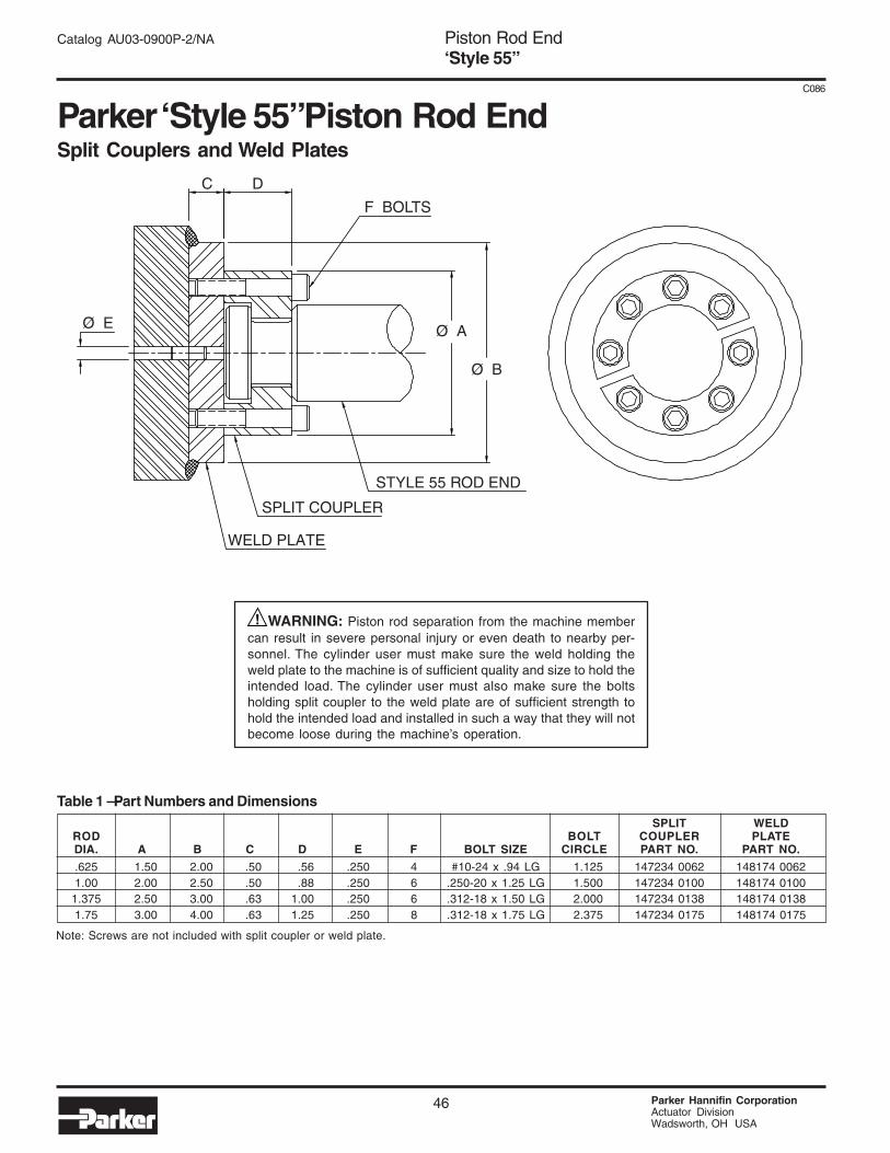
SPLIT WELDROD BOLT COUPLER PLATEDIA. A B C D E F BOLT SIZE CIRCLE PART NO. PART NO.
.625 1.50 2.00 .50 .56 .250 4 #10-24 x .94 LG 1.125 147234 0062 148174 00621.00 2.00 2.50 .50 .88 .250 6 .250-20 x 1.25 LG 1.500 147234 0100 148174 0100
1.375 2.50 3.00 .63 1.00 .250 6 .312-18 x 1.50 LG 2.000 147234 0138 148174 01381.75 3.00 4.00 .63 1.25 .250 8 .312-18 x 1.75 LG 2.375 147234 0175 148174 0175
Table 1 — Part Numbers and Dimensions
Note: Screws are not included with split coupler or weld plate.
Parker “Style 55” Piston Rod EndSplit Couplers and Weld Plates
WARNING: Piston rod separation from the machine membercan result in severe personal injury or even death to nearby per-sonnel. The cylinder user must make sure the weld holding theweld plate to the machine is of sufficient quality and size to hold theintended load. The cylinder user must also make sure the boltsholding split coupler to the weld plate are of sufficient strength tohold the intended load and installed in such a way that they will notbecome loose during the machine’s operation.