79
www.2n.cz Version 2N ® Helios IP Vario Door Entry IP Intercom Installation Manual 2.3
www.2n.czVersion
2N ® Helios IP VarioDoor Entry IP Intercom
Installation Manual
2.3

The 2N TELEKOMUNIKACE a.s. is a Czech manufacturer and supplier of telecommunicationsequipment.
The product family developed by 2N TELEKOMUNIKACE a.s. includes GSM gateways, privatebranch exchanges (PBX), and door and lift communicators. 2N TELEKOMUNIKACE a.s. hasbeen ranked among the Czech top companies for years and represented a symbol ofstability and prosperity on the telecommunications market for almost two decades. Atpresent, we export our products into over 120 countries worldwide and have exclusivedistributors on all continents.
2N is a registered trademark of 2N TELEKOMUNIKACE a.s. Any product and/or other®
names mentioned herein are registered trademarks and/or trademarks or brands protectedby law.
2N TELEKOMUNIKACE a.s. administers the FAQ database to help you quickly findinformation and to answer your questions about 2N products and services. Onwww.faq.2n.cz you can find information regarding products adjustment and instructions foroptimum use and procedures „What to do if...“.
2N TELEKOMUNIKACE a.s. hereby declares that the 2N product complies® Helios IP Variowith all basic requirements and other relevant provisions of the 1999/5/EC directive. Forthe full wording of the Declaration of Conformity see the CD-ROM (if enclosed) or ourwebsite at www.2n.cz.
This device complies with part 15 of the FCC Rules. Operation is subject to the followingtwo conditions: (1) This device may not cause harmful interference, and (2) this devicemust accept any interference received, including interference that may cause undesiredoperation.
The 2N TELEKOMUNIKACE a.s. is the holder of the ISO 9001:2009 certificate. Alldevelopment, production and distribution processes of the company are managed by thisstandard and guarantee a high quality, technical level and professional aspect of all ourproducts.
Content

Content 1. Product Overview . . . . . . . . . . . . . . . . . . . . . . . . . . . . . . . . . . 4
1.1 Components and Associated Products . . . . . . . . . . . . . . . . . . . . . . . . . . . . . . . 6 1.2 Terms and Symbols . . . . . . . . . . . . . . . . . . . . . . . . . . . . . . . . . . . . . . . . . . . . . . 18
2. Description and Installation . . . . . . . . . . . . . . . . . . . . . . . . . . 19 2.1 Before You Start . . . . . . . . . . . . . . . . . . . . . . . . . . . . . . . . . . . . . . . . . . . . . . . . . 20
2.2 Mechanical Installation . . . . . . . . . . . . . . . . . . . . . . . . . . . . . . . . . . . . . . . . . . . . 21 2.3 Electric Installation . . . . . . . . . . . . . . . . . . . . . . . . . . . . . . . . . . . . . . . . . . . . . . . 30
2.4 Completion . . . . . . . . . . . . . . . . . . . . . . . . . . . . . . . . . . . . . . . . . . . . . . . . . . . . . 41 2.5 Extending Module Connection . . . . . . . . . . . . . . . . . . . . . . . . . . . . . . . . . . . . . . 43
3. Function and Use . . . . . . . . . . . . . . . . . . . . . . . . . . . . . . . . . . 56 3.1 Configuration . . . . . . . . . . . . . . . . . . . . . . . . . . . . . . . . . . . . . . . . . . . . . . . . . . . 57
3.2 Intercom Control as Viewed by External User . . . . . . . . . . . . . . . . . . . . . . . . . . 62 3.3 Display-Equipped Intercom as Viewed by External User . . . . . . . . . . . . . . . . . . 65
3.4 Intercom Control as Viewed by Internal User . . . . . . . . . . . . . . . . . . . . . . . . . . . 68 3.5 Maintenance . . . . . . . . . . . . . . . . . . . . . . . . . . . . . . . . . . . . . . . . . . . . . . . . . . . . 70
4. Technical Parameters . . . . . . . . . . . . . . . . . . . . . . . . . . . . . . . 71
5. Supplementary Information . . . . . . . . . . . . . . . . . . . . . . . . . . 73 5.1 Troubleshooting . . . . . . . . . . . . . . . . . . . . . . . . . . . . . . . . . . . . . . . . . . . . . . . . . 74
5.2 Directives, Laws and Regulations . . . . . . . . . . . . . . . . . . . . . . . . . . . . . . . . . . . 75 5.3 General Instructions and Cautions . . . . . . . . . . . . . . . . . . . . . . . . . . . . . . . . . . . 77

42N TELEKOMUNIKACE a.s., www.2n.cz®
1. Product Overview
Here is what you can find in this section:
1.1 Components and Associated Products1.2 Terms and Symbols
Basic Features2N® Helios IP Vario is a highly reliable IP door access intercom provided with a lot ofuseful above-standard functions. Supporting the SIP standard and being compatiblewith the leading IP PBX and telephone suppliers, can make use2N® Helios IP Vario of all VoIP services.
2N® Helios IP Vario can be equipped with a colour camera, which displays the callingperson on the called party's video telephone or PC monitor.
2N® Helios IP Vario can be provided with up to 54 pre-programmed buttons. You canset up to three telephone numbers and time profiles for each of the buttons to increasethe accessibility of the called party.
2N® Helios IP Vario can be equipped with a numerical keypad to be used as a codelock for lock switch activating or telephone/subscriber number dialling.
2N® Helios IP Vario is equipped with an electric lock switch. You can control theswitch using a numerical keypad or, during a call, using any telephone set. Anadditional switch module can be installed if necessary. A wide range of settings allowfor a variety of applications.
2N® Helios IP Vario can also be provided with RFID card reader modules.
2N® Helios IP Vario is very easy to install. All you have to do is connect the systeminto your LAN via a network cable and feed it from a 12 V power supply or your PoEsupporting LAN.
Configure using your PC via any web browser. Use the 2N® Helios IP Vario IP

52N TELEKOMUNIKACE a.s., www.2n.cz®
to manage extensive systems easily and quickly.Manager 2N® Helios IP Vario
Advantages of UseBidirectional communication – acoustic echo cancellingIntegrated colour cameraOptional dial buttons including name tags with backlightOptional numerical keypad with backlightIntegrated electronic lock switches with wide setting optionsOptional integrated RFID card reader moduleLAN (PoE) or external 12 V power supplyConfiguration via web interface or dedicated PC applicationSIP 2.0 supportUp to 54 buttons pre-programmed buttonsUp to 1999 telephone directory positionsUp to 20 user time profilesVideo codecs (H.263, H.263+, H.264, MPEG-4, JPEG)Audio codecs (G.711, G.729, G.722, L16/16kHz)HTTP server for configurationSNTP client for time synchronisation with serverRTSP server for video streamingSMTP client for e-mail sendingTFTP client for automatic configuration and firmware update

62N TELEKOMUNIKACE a.s., www.2n.cz®
1.1 Components and Associated Products
Basic Units

72N TELEKOMUNIKACE a.s., www.2n.cz®
PartNo. 9137111(C)U
1 button
control of oneelectric lock
possibility ofconnecting card
reader, extenders orinformation panel or
additional switch
PartNo. 9137131(C)U
3 buttons
control of oneelectric lock
possibility ofconnecting card
reader, extenders orinformation panel or
additional switch
PartNo. 9137161(C)U
6 buttons
control of oneelectric lock
possibility ofconnecting card
reader, extenders orinformation panel or
additional switch
PartNo. 9137111(C)KU
1 button
keypad
control of oneelectric lock
possibility ofconnecting card
reader, extenders orinformation panel or
additional switch
PartNo. 9137131(C)KU
3 buttons
keypad
control of oneelectric lock
possibility ofconnecting card
reader, extenders orinformation panel or
additional switch
PartNo. 9137161(C)KU
6 buttons
keypad
control of oneelectric lock
possibility ofconnecting card
reader, extenders orinformation panel or
additional switch
PartNo. 9137160(C)KDU
6 buttons
graphic display
keypad
control of one electriclock
possibility ofconnecting card
reader, extenders orinformation panel or
additional switch

82N TELEKOMUNIKACE a.s., www.2n.cz®
(C) = integrated camera
Extending Modules
9135181EPart No. Extending module
8 buttons
Dimension of the module 100x 210 x 29 mm
9135182EPart No. Extending module
16 buttons
Dimension of the module 100x 210 x 29 mm
9135310EPart No. Info panel
Backlit panel withoutbuttons; used
for insertion of atelephone directory,company logo, house
number, etc.

92N TELEKOMUNIKACE a.s., www.2n.cz®
Extenders
9135301EPart No. Spare button name plate
9135311EPart No. Info panel – name plate
Replacing cover for four name tags.Helps you use a half of the extending
module for insertion of a telephone directory,working hours, etc.
9135302EPart No. Spare double-button name plate
Tip
All units can be surface mounted without needing any additionalaccessories.To make them even more robust and resistant, use a Vandal Resistantmask.
Caution
For flush or outdoor mounting you need to use the accessories; see theMounting Accessories subsection.

102N TELEKOMUNIKACE a.s., www.2n.cz®
Mounting Accessories
9135331EPart No. Surface 1-module roof
(103 × 218 ×Dimensions:60) mm (W × H × D)
9135351EPart No. Wall mounting boxwith
1-module frame (125 × 235 ×Dimensions:
46) mm (W × H × D) (110 × 220 × 50)Wall hole:±5 mm
9135361EPart No. Wall mounting boxwith
1-module roof (129 ×Roof dimensions:
240 × 41) mm (W × H × D) (110 × 220 × 50)Wall hole:±5 mm
9135332EPart No. Surface 2-module roof
(203 × 218 ×Dimensions:60) mm (W × H × D)
9135352EPart No. Wall mounting boxwith
2-module frame (225 × 235 ×Dimensions:
46) mm (W × H × D) (210 × 220 × 50)Wall hole:±5 mm
9135362EPart No. Wall mounting boxwith
2-module roof (229 ×Roof dimensions:
240 × 41) mm (W × H × D) (210 × 220 × 50)Wall hole:±5 mm
The mounting accessories are made of stainless steel. For outdoor applications, the useof the roof is required unless weather protection is provided otherwise. The box withframe (without roof) allows for installation of in indoor2N® Helios IP Vario applications so that the unit does not practically stick out (up to 1 mm).

122N TELEKOMUNIKACE a.s., www.2n.cz®
Part No. 91378365
2N Indoor Touch® -black
The elegant internal touchpanel, 2N Indoor Touch®
, is suitable for all 2N®
intercoms. OnHelios IPthe panel’s display not onlycan you find out who is atthe door, but also start a
conversation with thevisitor, open the lock orturn on the light in the
entrance hall.
Part No. 91378365WH
-2N Indoor Touch®
white
The elegant internal touchpanel, 2N Indoor Touch®
, is suitable for all 2N®
intercoms. OnHelios IPthe panel’s display not onlycan you find out who is atthe door, but also start a
conversation with thevisitor, open the lock orturn on the light in the
entrance hall.
Part No. 91378366
-2N Indoor Touch®
black
WiFi
The elegant internal touchpanel, 2N Indoor Touch®
, is suitable for all 2N®
intercoms. OnHelios IPthe panel’s display not onlycan you find out who is atthe door, but also start a
conversation with thevisitor, open the lock orturn on the light in the
entrance hall.
Part No. 91378367
-2N Indoor Touch®
black
WiFi + NFC
The elegant internal touchpanel, 2N Indoor Touch®
, is suitable for all 2N®
intercoms. OnHelios IPthe panel’s display not onlycan you find out who is atthe door, but also start a
conversation with thevisitor, open the lock orturn on the light in the
entrance hall.
Part No. 91378368
-2N Indoor Touch®
black
NFC
The elegant internal touchpanel, 2N Indoor Touch®
, is suitable for all 2N®
intercoms. OnHelios IPthe panel’s display not onlycan you find out who is atthe door, but also start a
conversation with thevisitor, open the lock orturn on the light in the
entrance hall.

132N TELEKOMUNIKACE a.s., www.2n.cz®
VoIP Telephones
91378357Part No. Grandstream GXV3240 VoIP video
telephone
GXV3240 is the successor to the popularGXV3140 model, which allows comfortablevideo calls in the IP network. Touchscreen
and keyboard control.
91378358Part No. Grandstream GXV3275 VoIP video
telephone
GXV3275 is the successor to thepopular GXV3175 model, which allows
comfortable video calls in the IPnetwork. Touchscreen control.
Electric Locks
932070EPart No. BEFO 1211
12 V / 600 mA
932080EPart No. BEFO 1221 with momentum
pin
12 V / 600 mA
For opening of the lock ashort electrical impuls is
sufficient, which unlocks thelock. Lock is then open untilsomeone closes the door.
932090EPart No. BEFO 1211MB withmechanical blocking
12 V / 600 mA
Enables mechanically close oropen the lock. When opened,the lock is open all the time.When closed, it behaves as
standart electrical lock.
Tip
FAQ: Electric locks - Difference between locks in 2N Helios IP accesories®

142N TELEKOMUNIKACE a.s., www.2n.cz®
Power Supply
Part. No. 91378100
PoE injector - withoutcable
Part. No.91378100E
PoE injector - with EUcable
Part. No.91378100US
PoE injector - with UScable
91341481EPart No. Adapter 12 V / 2 A
A stabilised power supply has to be usedif the Ethernet (PoE) power supply is not
available.
932928Part No. 12 V transformer
Additional Modules

152N TELEKOMUNIKACE a.s., www.2n.cz®
9137310EPart No. Enables control of asecondary device,
NO/NC passivecontacts. Time
unlimited switching upto 48 V / 2 A.
9137430EPart No.
Card reader 125kHzInternal RFID card
reader for installation inthe basic module of the
2N® Helios IP Vario intercom. Allows the
use of EM4100, EM4102and HID Proximitycards. Another two
switches, two logicalinputs and a Wiegandinterface are available.It is compatible with all
2N® Helios IP Vario models.
Part No. 9137420E
USB RFID card reader 125kHzExternal RFID card reader for
connection to a PC using a USBinterface. Suitable for system
management and the addition ofEM41xx cards via the PC
application, 2N Helios IP®
.Manager
9159010Part No. Security Relay
A handy add-on thatsignificantly enhancesdoor entry security asit prevents tamperingwith the intercom andforced opening of thelock. To be installed
between intercom andlock, powered by the
intercom.
9159011Part No. Wiegand Isolator
The 2N Helios IP®
isWiegand Isolatordesigned for galvanic
isolation of two devicesseparately power
supplied andinterconnected via theWiegand bus. The 2N®
Helios IP Wiegand protects theIsolator
interconnected devicesagainst communicationerrors and/or damage.
9137410EPart No. External IP Relay - 1 output
Standalone IP device which can becontrolled by HTTP commands sentby Helios IP intercom, which canthus control devices on unlimited
distance.

162N TELEKOMUNIKACE a.s., www.2n.cz®
9137411EPart No. External IP Relay - 4
outputs, PoE
Standalone IP devicewhich can be
controlled by HTTP commands sent by
Helios IP intercom,which can thus controldevices on unlimited
distance.
9134165EPart No.
EM4100 type RFID card
9134166EPart No. EM4100 type RFID key fob
Part No. 9159013
Exit button
(suitable for InternalRFID card reader or
Security relay)
A button forconnection to a logicinput for opening a
door inside a building.
Part No. 9159012
Magnetic door contact
(suitable for InternalRFID card reader)
Part No. 9159014EU/US/UK
2N 2Wire®
(set of 2 adaptors and powersource for EU/US/UK)
The converter allows2N 2Wire®
you to use existing wiring (2 wires)from your original door bell or doorintercom to connect any IP device.
You don’t have to configureanything, and you only need one
unit at each end of the2N 2Wire®
cable and a power sourceconnected to at least one of theseunits. The unit then2N 2Wire®
provides power not only to thePoEsecond converter, but also to allother connected IP end devices.

172N TELEKOMUNIKACE a.s., www.2n.cz®
Part No. 9159030External 125kHz RFID
card readerSecondary reader for
connection to aninternal reader. Allowscontrol of card entry
from both sides of thedoor. IP67 cover, alsosuitable for exteriors.Reads EM4100 and
EM4102 cards.
Part No. 9154004
Water-proof metalbutton
(suitable for InternalRFID card reader)
Tip
For more accessories and particular advice please contact your localdistributor of 2N products.

182N TELEKOMUNIKACE a.s., www.2n.cz®
1.2 Terms and Symbols
The following symbols and pictograms are used in the manual:
Safety
abide by this information to prevent persons from injury.Always
Warning
abide by this information to prevent damage to the device.Always
Caution
Important information for system functionality.
Tip
Useful information for quick and efficient functionality.
Note
Routines or advice for efficient use of the device.

192N TELEKOMUNIKACE a.s., www.2n.cz®
2. Description and Installation
Here is what you can find in this section:
2.1 Before You Start2.2 Mechanical Installation2.3 Electric Installation2.4 Completion2.5 Extending Module Connection

202N TELEKOMUNIKACE a.s., www.2n.cz®
2.1 Before You Start
Product Completeness Check
Before you start please check whether the contents of the package of your new 2N® complies with the following list. Helios IP Vario
1× 2N® Helios IP Vario1× spare seal1× drilling template1× hexagonal wrench1× spare name plate1× terminal block plug2× screw2× dowel

212N TELEKOMUNIKACE a.s., www.2n.cz®
2.2 Mechanical Installation
Overview of Installation TypesAn overview of the installation types and the list of the required components areprovided in the table below.

222N TELEKOMUNIKACE a.s., www.2n.cz®
Installationtype Symbol What you need for installation
Indoor, onsurface 2N® Helios IP Vario only
Indoor,flushmounting
2N® Helios IP VarioBox with 1-module frame or9135351EBox with 2-module frame 9135352E
Outdoor,on surface
2N® Helios IP VarioSurface 1-module roof or9135331ESurface 2-module roof 9135332E
Outdoor,flushmounting
2N® Helios IP VarioWall mounting box with 1-module roof
or Wall mounting box with9135361E 2-module roof 9135362E
Withincreasedresistance
2N® Helios IP VarioVandal resistant mask with box, versionaccording to the assembly
Indoorapplicationmeans
Indoor areas with a low relative airhumidity value (e.g., hallways, officesand other heated rooms).Indoor areas where humidity
on walls condenses but never flows (porches, storage areas,down the walls
industrial areas, e.g.).Outdoor areas where protection againstrain and water flowing down the wall
(sheds, passages. e.g.).is provided
Outdoorapplicationmeans
Environments where the product isexposed to rain or where water may flowdown the walls (fence, outer wall of abuilding, e.g.).

232N TELEKOMUNIKACE a.s., www.2n.cz®
Caution
The warranty does not apply to the product defects and failures arisen asa result of improper mounting (in contradiction herewith). Themanufacturer is neither liable for damage caused by theft within an areathat is accessible after the attached electric lock is switched. The productis not designed as a burglar protection device except when used incombination with a standard lock, which has the security function.When the proper mounting instructions are not met, water might get inand destroy the electronics. It is because the intercom circuits are undercontinuous voltage and water infiltration causes an electro-chemicalreaction. The manufacturer's warranty shall be void for products damagedin this way!

242N TELEKOMUNIKACE a.s., www.2n.cz®
1.
2.
3.
Surface Mounting
Drill holes according to the template included in the 2N ® Helios IP Vario supply. Insert the included dowels in the wall holes.
Use the hexagon key wrench included in the supply and remove the 2N ® Heliosmetal cover. Remove the screw in the lower part of the metal cover andIP Vario
fold out the cover.
Use a cross-head screwdriver to remove the plastic cover and demount thecover.

252N TELEKOMUNIKACE a.s., www.2n.cz®
3.
4.
5. 6. 7.
In multiple-module assemblies connect the boxes, placing the basic module tothe left and the extending modules to the right. The interconnecting cable shallbe connected later!
Install blank modules on the unused side holes as shown in Figure previous step.If you are installing a roof module, put it on the wall now.Fix on the wall with screws. Carry the supply cables2N ® Helios IP Vario (Ethernet, lock, power cables) to the basic module box through one of the holes. Seal the screw hole carefully with some cement or non-aggressive silicone toavoid water infiltration.
WarningNever remove the main board or camera electronics from under thelower cover while installing . Do not2N® Helios IP Vario disconnect the camera flat cable from the main board. Do not bendand press upon the flat cable either.

262N TELEKOMUNIKACE a.s., www.2n.cz®
7.
8.
9.
While installing a roof module, paste its top and side edges to the wall usingsilicone glue to prevent water from flowing into the box along or around thecables.
Connect the cables as described in subsection 2.4, Mounting – ElectricalInstallation. Make sure that the cables are not squeezed while installing theplastic cover. For the correct cable installation.
WarningMake sure that the mounting surface for the 2N® Helios IP Vario door communicator is perfectly flat. Avoid mechanical overload uponthe bottom part of the cover. An incorrect installation on an unevensurface may lead to cover deformation and thus productmalfunctions.

272N TELEKOMUNIKACE a.s., www.2n.cz®
9.
10.
11.
12.
13.
14.
15.
Remove the protective foil from the display (for display-equipped 2N ® Helios IPversions only).Vario
Make sure that the cables are placed properly inside and that none of themobstructs a perfect cover closure.Make sure that the three loudspeaker holder feet fit into the board holes. Keepthe required loudspeaker position to make the seal work properly.Having mounted the unit on the wall and connected all cables, replace the plasticcover using cross-recessed screws.
Take out the name plates from the plastic cover. Use a flat-bladed screwdriver,for example.
Remove the inserts from the name plates.
WarningRemember to tighten all the four corner screws to fix theloudspeaker seal after electric installation to avoid water in-leak! A
cross-head screwdriver is recommended.PZ1

282N TELEKOMUNIKACE a.s., www.2n.cz®
15.
16.
17. 18.
19.
20.
Insert the printed foil labels.
Put the inserts back in the name plates.Replace the name plates, clicking them into position. The name plates hold thematt foil inserted underneath.Check whether a silicone seal is inserted in the top groove of the plastic cover. Aspare seal package is included.Close the metal cover and fix it with screws.
Outdoor Installation Rules
Always connect button backlighting – it is used for heating.The joint between the roof module and the wall must be filled with a waterproofcement to prevent water in-leak (see Figure 2.5).Water must not leak in along or around the cables.
Name Tag Material and Printing
Each package includes a sheet of transparent foil for laser2N ® Helios IP Vario printing. Cut the printed foil into pieces and insert the labels in the name plates. Do notuse paper to avoid water in-leak and paper damage.
Red arrows are printed on the name plate. Make sure that the text and the arrow donot overlap. We recommend you to use a template (MS Word) available at fwww.2n.czor printing.
Warning
Make sure that all the holes are filled with a waterproof material – top,around the cables and screws - and that a side sealing is ensured.

292N TELEKOMUNIKACE a.s., www.2n.cz®
Flush MountingFollow the installation instructions included in the flush mounting box delivery.
Caution
The warranty shall not apply to product failures and defects caused byimproper installation (contrary to these instructions). The manufacturer isneither liable for damages caused by theft within an area that isaccessible after the attached electric lock is switched. The product is notdesigned as a burglar protection device except when used in combinationwith a standard lock, which has the security function.

302N TELEKOMUNIKACE a.s., www.2n.cz®
2.3 Electric Installation2N ® Helios IP Vario is designed for connection in the Ethernet computer network(10/100BASE-T) using a UTP cable. Use a CAT 5e UTP cable at least for connection.
2N ® Helios IP Vario is fed through the PoE (Power over Ethernet) technology. Noadditional cabling is therefore necessary. If your Ethernet is not equipped with the PoEtechnology, it is possible to use a PoE injector, Part No. 91378100. As an alternative,you can use a power adapter, Part No. 91341481E. is configured2N ® Helios IP Vario over an integrated administration web server, which can be controlled from any webbrowser, e.g., Mozilla Firefox.
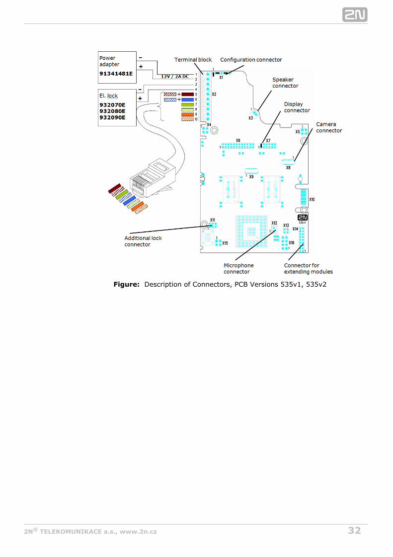
Description of Printed Circuit Board ConnectorsIn figure bellow you can see the location of the printed circuit board (PCB) connectors.Connectors to which the accessories can be connected and connectors that serve forconfiguring are indicated on the board. The UTP cable for the2N ® Helios IP Vario Ethernet connection is to be connected to the terminal block X2 as shown in tablebelow. The terminal block can be removed from the PCB. The connection of each of theconnectors is described in the subsections below.
Tip
Video Tutorial: Door communication system 2N Helios IP Vario -®
.Electrical Installation

312N TELEKOMUNIKACE a.s., www.2n.cz®
Description of Connectors, PCB Version 530v2Figure:
322N TELEKOMUNIKACE a.s., www.2n.cz®
Description of Connectors, PCB Versions 535v1, 535v2Figure:

332N TELEKOMUNIKACE a.s., www.2n.cz®
1.
2. 3. 4.
Description of Connectors, PCB Versions 535v5Figure:
Terminal Block X2 ConnectionTerminal block X2 includes 10 terminals whose functions are distinguished by colour.Terminals 5–10 are used for connecting to the2N ® Helios IP Vario Ethernet. Terminals 3–4 are designed for connecting the electric lock and terminals 1–2help connect an external 12 V / 2 A DC power supply if no PoE power supply isavailable.
The terminal block is included in the package. To adjust an already installed 2N®
, disconnect it IP from the power supply. Then pull to removeHelios IP Vario the terminal block from the printed circuit board.Insert the wires under the respective terminals.Tighten the terminals using a flat screwdriver.Replace the terminal block to the printed circuit board.
Caution
Make sure that the cables leading through the 2N® Helios IP Vario cover bottom groove are installed properly. For the correct installation ofthe cables refer to Figure 2.7.

342N TELEKOMUNIKACE a.s., www.2n.cz®
Ethernet ConnectionFor the connections and meanings of the wires see the table below. Join UTP cablewires 4 (blue) and 5 (white-blue) and attach them under terminal 6 on 2N ® Helios IP
In the same way, join wires 7 and 8 and place them under terminal 5 of Vario 2N ®
.Helios IP Vario
Terminal Block ConnectionsFigure:
Electric Lock ConnectionThe electric lock can be connected to terminals 3 and 4 of terminal block X2.
Terminal Block Connection for Electric LockFigure:
Terminals 3 and 4 are connected to a relay on the board. The 2N ® Helios IP Vario relay terminals may act as normally open or normally closed contacts. Configuration isperformed through the configuration connector X1 as described in the
352N TELEKOMUNIKACE a.s., www.2n.cz®
1.
2.
Configuration Connector Connection subsection. Set on the configuration connectorwhether the electric lock will be powered from an external or internal power supply.
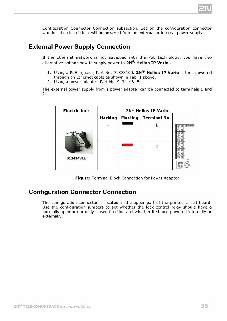
External Power Supply ConnectionIf the Ethernet network is not equipped with the PoE technology, you have twoalternative options how to supply power to .2N ® Helios IP Vario
Using a PoE injector, Part No. 91378100. is then powered2N ® Helios IP Vario through an Ethernet cable as shown in Tab. 1 above.Using a power adapter, Part No. 91341481E.
The external power supply from a power adapter can be connected to terminals 1 and2.
Terminal Block Connection for Power AdapterFigure:
Configuration Connector ConnectionThe configuration connector is located in the upper part of the printed circuit board.Use the configuration jumpers to set whether the lock control relay should have anormally open or normally closed function and whether it should powered internally orexternally.

362N TELEKOMUNIKACE a.s., www.2n.cz®
Connection of Configuration Connector JumpersFigure:
Display ConnectorThe display connector includes the name plate backlighting ON/OFF switching pins and
resetting pins. The remaining pins are intended for display2N® Helios IP Vario connection.

372N TELEKOMUNIKACE a.s., www.2n.cz®
1. 2.
3. 4. 5.
6.
Resetting procedure
Switch off.2N® Helios IP Vario Connect the jumper into the resetting (default setting) position (put the displayswitch into the F_RES position in the display-equipped models with 535v1 and535v2 board versions).Switch on and wait for the acoustic start signalling.2N® Helios IP Vario Switch off.2N® Helios IP Vario Remove the jumper from the resetting (default setting) position (put the displayswitch into the NORMAL position in the display-equipped models with 535v1 and535v2 board versions).Switch on.2N® Helios IP Vario
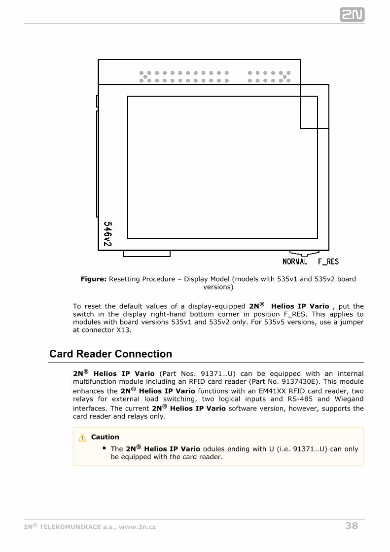
Configuration Jumpers on Display ConnectorFigure:
382N TELEKOMUNIKACE a.s., www.2n.cz®
Resetting Procedure – Display Model (Figure: models with 535v1 and 535v2 board)versions
To reset the default values of a display-equipped , put the2N® Helios IP Vario switch in the display right-hand bottom corner in position F_RES. This applies tomodules with board versions 535v1 and 535v2 only. For 535v5 versions, use a jumperat connector X13.
Card Reader Connection
2N® Helios IP Vario (Part Nos. 91371…U) can be equipped with an internalmultifunction module including an RFID card reader (Part No. 9137430E). This moduleenhances the functions with an EM41XX RFID card reader, two2N® Helios IP Vario relays for external load switching, two logical inputs and RS-485 and Wiegandinterfaces. The current software version, however, supports the2N® Helios IP Vario card reader and relays only.
Caution
The odules ending with U (i.e. 91371…U) can only2N® Helios IP Vario be equipped with the card reader.

392N TELEKOMUNIKACE a.s., www.2n.cz®
1. 2. 3. 4.
5.
6. 7. 8.
Card Reader Mounting
Power off .2N ® Helios IP Vario Use a hexagonal wrench to unscrew and remove the metal cover.Use a cross-head screwdriver to unscrew and remove the plastic cover.Connect the reader module into the basic unit bottom2N ® Helios IP Vario connector making sure that the microphone cable lies under the module.Use the enclosed screws to fix the reader module to the 2N ® Helios IP Vario plastic base.Connect the wires for the reader module interface(s) if necessary.Replace and fix the plastic cover using cross-head screws.Replace and screw back the metal cover.

402N TELEKOMUNIKACE a.s., www.2n.cz®
Available switchesLocation Name Description
Basic Unit Relay 1
Passive switch: NO and NC contacts, up to 30 V / 1 AAC/DC
Active switch output: 10 up to 14 V DC depending onpower supply (PoE: approx. 14 V; adaptor: same voltageas power supply), max 700 mA
AdditionalSwitch
(Part No.9137310 E)
Relay 2 Passive switch: NO and NC contacts, up to 30 V / 1 AAC/DC
Internal RFIDCard Reader125 kHz
(Part No.9137430 E)
Relay 1(CardReader)
Passive switch: NO and NC contacts, up to 30 V / 1 AAC/DC
Relay 2(CardReader)
Passive switch: NO and NC contacts, up to 30 V / 1 AAC/DC

412N TELEKOMUNIKACE a.s., www.2n.cz®
1.
2.
3.
2.4 CompletionRemember to seal the cable passage hole properly to2N® Helios IP Vario avoid moisture in-leak and damage to electronics due to condensation.Make sure that the wires inside are not squeezed and2N® Helios IP Vario insert the plastic top cover (a transparent plastic mould) carefully making itscontacts plug into the electronics board connectors. Push the plastic cover intoposition moderately. If the part swings over an obstacle or one corner is higherthan the others, remove the cover and find the obstacle. Then tighten the cornerscrews properly.Mounting the metal sheet cover follow the steps included in the subsectiondedicated to name plate removal. Make sure that the cover fits well and isperfectly flat. If its bottom part is loose, the mounting wall is probably uneven.Support the corners to avoid bending.2N® Helios IP Vario
Most Frequent Mounting ErrorsFor illustration, a part of the plastic cover is removed in the figures below to reveal thesealed loudspeaker and the cover-seal touch point. The cross section plane is markedwhite for better orientation.
Caution
An improper mounting may significantly deteriorate the button function.A poor outdoor mounting may cause water in-leak and damage to theelectronics.

432N TELEKOMUNIKACE a.s., www.2n.cz®
2.5 Extending Module Connection2N ® Helios IP Vario allows to connect following extending modules:
Extending button modulesAdditional SwitchInternal RFID Card Reader 125 kHzSecurity RelayWiegand Isolator
Extending button modules
2N ® Helios IP Vario features an easy installation of extending button modules.Extending modules are connected using a single cable (included in every extenderdelivery) in a chain pattern (every additional unit is connected with the previous one).Each extending module has two connectors – an input connector (for connectiontowards the basic unit) and an output connector (for connection2N ® Helios IP Vario of another, more remote unit). Be sure to maintain the correct orientation of the unitsand avoid connector mismatch to ensure a proper function of the device!
Connection of One-Row-Button Extending ModulesFigure:

442N TELEKOMUNIKACE a.s., www.2n.cz®
Maximum Count of Extenders
9135181E (1× 8 buttons) 6 5 4 3 2 1 0
9135182E (2× 8 buttons) 0 0 1 1 2 2 3
Table 2.6 Optional Extension
The table above shows how to combine modules with single (whole) and doublebuttons.
Module Cable Interconnection
The cable is included in every extending module delivery. Both its ends are thesame. Configuration is 1:1. Connectors cannot be shifted or inserted converselybecause they are equipped with a so-called key.The basic unit is always on the left. Extenders are chain-connected, i.e. each islinked with its neighbour.The cable cannot be driven through the box interconnecting holes until the boxeshave been connected (see subsection 2.3 Mounting – Mechanical Installation).
Figure 2.16 Connection of Two-Button-Row Extending Module
Caution
The extending modules must be connected mutually and with the basicunit by means of a formed piece supplied with the extending module!!!

452N TELEKOMUNIKACE a.s., www.2n.cz®
Button Numbering
Button numbering – one-button with a whole-button set
Button numbering – whole-button sets
462N TELEKOMUNIKACE a.s., www.2n.cz®
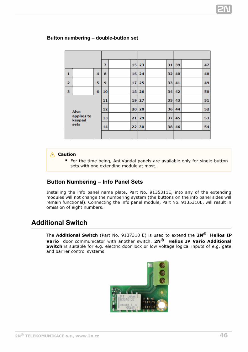
Button numbering – double-button set
Button Numbering – Info Panel Sets
Installing the info panel name plate, Part No. 9135311E, into any of the extendingmodules will not change the numbering system (the buttons on the info panel sides willremain functional). Connecting the info panel module, Part No. 9135310E, will result inomission of eight numbers.
Additional Switch
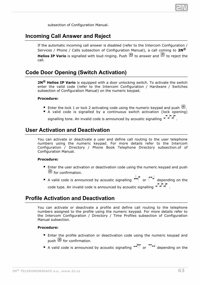
The (Part No. ) is used to extend the Additional Switch 9137310 E 2N® Helios IPdoor communicator with another switch. Vario 2N ® Helios IP Vario Additional is suitable for e.g. electric door lock or low voltage logical inputs of e.g. gateSwitch
and barrier control systems.
Caution
For the time being, AntiVandal panels are available only for single-buttonsets with one extending module at most.

472N TELEKOMUNIKACE a.s., www.2n.cz®
Function:
The adds one additional switch to the 2N ® Helios IP Vario Additional Switch 2N ®
basic unit. Helios IP Vario
Specifications:
Passive switch: NO and NC contacts, up to 30 V / 1 A AC/DC
Module mounting:
Switch off the intercom before module installation.
Module settings:
Refer to the for details.2N Helios IP Configuration Manual®
Caution
Before installing the module, make sure that the current and voltagelimits of the module will not be exceeded in your application (refer to theTechnical Parameters chapter). In no case use this module for mainsvoltage switching!

482N TELEKOMUNIKACE a.s., www.2n.cz®
Connection:
Switch ConnectionNormally opened NO – CNormally closed NC – C
Internal RFID Card Reader 125 kHzThe Internal RFID Card Reader (Part No. 9137430 E) is used for reading RFID cardIds in the 125 kHz band. This module is intended for mounting into the 2N ® Helios IPVario model 91371....U.
Function:
The Internal RFID Card Reader adds these features2N ® Helios IP Vario
RFID card reader
492N TELEKOMUNIKACE a.s., www.2n.cz®
2 relay outputs2 digital inputsWIEGAND interfaceSignalling outputs (LED / buzzer)
Specifications:
Card reader
Compatible with EM4100 / EM4102 / HID Prox RFID cards®
Working frequency: 125 KHzMinimum reading distance: 10 mm above cover2N ® Helios IP Vario
Relay outputs
Switching contact30V / 1A AC / DC
Logical inputs
Active mode – requires external voltage (JP2 jumper OFF)
U = min +2.5 VIN-ONU = max +1.5 VIN-OFFU = +48 VIN maxI (U +48 V) = max 1 mAIN IN
Passive mode – requires external contact only (JP2 jumper ON)
U = approx. 8.3 VOUTI = approx. 0.5 mALOOP
Signalling outputs
5 V or 12V DC voltage270 ohm current limiter
WIEGAND interface
Input / Output (as programmed)

502N TELEKOMUNIKACE a.s., www.2n.cz®
Module mounting:
Power off .2N Helios IP Vario®
Use a hexagonal wrench to unscrew and remove the metal cover.Use a cross-head screwdriver to unscrew and remove the plastic cover.Connect the reader module into the basic unit bottom2N Helios IP Vario®
connector making sure that the microphone cable lies under the module.Use the enclosed screws to fix the reader module to the 2N Helios IP Vario®
plastic base.Connect the wires for the reader module interface(s) if necessary.Replace and fix the plastic cover using cross-head screws.Replace and screw back the metal cover.
Module settings:
Refer to the for details.2N Helios IP Configuration Manual®
Connection:
Security RelayThe (Part No. 9159010) is used for enhancing security between theSecurity Relayintercom and the connected electric lock. The is2N Helios IP Security Relay®
designed for any intercom model with firmware versions 1.15 and2N Helios IP®
higher. It significantly enhances security of the connected electric lock as it preventslock opening by forced intercom tampering.

512N TELEKOMUNIKACE a.s., www.2n.cz®
Function:
The is a device installed between an intercom (outside2N Helios IP Security Relay®
the secured area) and the electric lock (inside the secured area). The 2N Helios IP®
includes a relay that can only be activated if the valid opening code isSecurity Relayreceived from the intercom.
Specifications:
Passive switch: NO and NC contacts, up to 30 V / 1 A AC/DCActive switch output: 12 V / 700 mA DCDimensions: (56 × 31 × 24) mmWeight: 20 g
Installation:
Install the onto a two-wire cable between the intercom2N Helios IP Security Relay®
and the electric lock inside the area to be secured (typically behind the door). Thedevice is powered and controlled via this two-wire cable and so can be added to anexisting installation. Thanks to its compact dimensions, the device can be installed intoa standard mounting box.
Connection:
Connect the to the intercom as follows:2N Helios IP Security Relay®
To the intercom active output (OUT1 or OUT2) , orTo the intercom relay output with a 12 V DC serial external power supply.
Connect the electric lock to the output as follows:2N Helios IP Security Relay®
To the active 12 V / 700 mA DC output, orTo the relay output with a serial external power supply.
The device also supports a Departure button connected between the ‘PB’ and ‘-HeliosIP’ terminals. Press the Departure button to activate the output for 5 seconds.
Status signalling:
Green LED Red LED Statusblinking off Operational modeon off Activated outputblinking blinking Programming mode – waiting for initialisationon blinking Error – wrong code received

522N TELEKOMUNIKACE a.s., www.2n.cz®
Configuration:
Connect the to the properly set intercom switch2N Helios IP Security Relay®
output; refer to the . Make sure that one2N Helios IP Configuration Manual®
LED at least on the is on or blinking.2N Helios IP Security Relay®
Press and hold the Reset button for 5 seconds to2N Helios IP Security Relay®
put the device in the programming mode (both the red and green LEDs areblinking).Activate the intercom switch using the keypad, telephone, etc. The first code sentfrom the intercom will be stored in the memory and considered valid. After codeinitialisation, the will pass into the operational2N Helios IP Security Relay®
mode (the green LED is blinking).
Connection:
Wiegand IsolatorThe (Part No. 9159011) is usef for galvanic isolation of theWiegand IsolatorWiegand bus.
The is designed for galvanic isolation of two2N Helios IP Wiegand Isolator®
Tip
FAQ: 2N Helios IP Security Relay – what it is and how to use it with 2N® ®
Helios IP intercom?
Tip
Video Tutorial: Door intercoms 2N Helios IP - Security Relay®

532N TELEKOMUNIKACE a.s., www.2n.cz®
devices with separate power supply and interconnected via the Wiegand bus. The 2N®
protects the interconnected devices against Helios IP Wiegand Isolatorcommunication errors and/or damage.
Connection of the to a security system unit is a typical2N Helios IP Card Reader®
example of application.
Function:
The separates galvanically a two-wire Wiegand bus2N Helios IP Wiegand Isolator®
in one direction and a status LED signal in the other direction. The module is powersupplied from the Wiegand bus receiver side.
Specifications:
2-wire WIEGAND IN2-wire WIEGAND OUTLED IN switched against GND on WIEGAND OUT sideOpen LED OUT switched against GND on WIEGAND IN side (up to 24 V / 50 mA)5 to 16V / 10 mA power supply from Wiegand bus receiver side500 V DC isolation strength

562N TELEKOMUNIKACE a.s., www.2n.cz®
3. Function and Use
This section describes the basic and extending functions of the the 2N® Helios IPproduct. Vario
Here is what you can find in this section:
3.1 Configuration3.2 Intercom Control as Viewed by External User3.3 Display-Equipped Intercom as Viewed by External User3.4 Intercom Control as Viewed by Internal User3.5 Maintenance

572N TELEKOMUNIKACE a.s., www.2n.cz®
3.1 ConfigurationUse a PC equipped with any web browser to configure :2N® Helios IP Vario
Launch your web browser (Internet Explorer, Firefox, etc.).Enter the IP address of your intercom (http://192.168.1.100/, e.g.).Log in using the user name and password.Admin 2n
You have to know the IP address of your device to log in to the integrated web server.By default, is switched into the dynamic IP address mode, i.e. it2N® Helios IP Vario obtains the IP address automatically if a properly set DHCP server is available in yourLAN. If no such DHCP server is available, you can operate in the2N® Helios IP Vario static IP address mode.
If your device remains inaccessible (you have forgotten the IP address, or the LANconfiguration has changed, for example), change the LAN settings using the buttons onthe device.
IP Address Retrieval
Take the following steps to retrieve the IP address:2N® Helios IP Vario
Connect (or, if connected, disconnect and reconnect) to2N® Helios IP Vario the power supply.
Wait for the second sound signal .1-button models: Press the quick dial button on the basic unit five times.
3-buttons models: Press the second quick dial button on the basic unit fivetimes.

582N TELEKOMUNIKACE a.s., www.2n.cz®
6-buttons models: Press the fifth quick dial button on the basic unit fivetimes.
2N ® Helios IP Vario will read its IP address.If the address is 0.0.0.0, it means that the intercom has not obtained the IPaddress from the DHCP server.
Static IP Address SettingFollow the instructions below to enable the static IP address mode:
Connect to the power supply (or, disconnect and reconnect2N® Helios IP Vario it if already connected).
Wait for the first acoustic signal .Press following buttons sequentially:
1, 1, 1, 2, 2, 3 for 3-buttons models
Note
Be sure to press the button sequence within thirty seconds after thesound signal for security reasons. Up to 2 s intervals are allowed betweenthe presses.

592N TELEKOMUNIKACE a.s., www.2n.cz®
Figure 3.1 Switching to static IP address
4, 4, 4, 5, 5, 6 for 6-buttons modely
The acoustic signal indicates mode switching.Wait until the device is restarted automatically.
The device will have the following network parameters after restart:
IP address – 192.168.1.100Network mask – 255.255.255.0Default gateway – 192.168.1.1
Note
The 1, 1, 1, 2, 2, 3 sequence must be entered within 30 seconds after thefirst sound signal for security reasons. The inter-digit delay may be 2 s atmost.

602N TELEKOMUNIKACE a.s., www.2n.cz®
Dynamic IP Address SettingFollow the instructions below to enable automatic getting of network parameters fromthe DHCP server:
Connect to the power supply (or, disconnect and reconnect2N® Helios IP Vario it if already connected).
Wait for the first acoustic signal Press following buttons sequentially:
2, 1, 1, 2, 2, 3 for 3-buttons models
Figure 3.2 Switching to dynamic IP address
5, 4, 4, 5, 5, 6 for 6-buttons modely
The acoustic signal indicates mode switching.Wait until the device is restarted automatically.
2N® Helios IP Vario gets the IP address upon restart only if the DHCP server isconfigured properly.
Note
The 2, 1, 1, 2, 2, 3 sequence must be entered within 30 seconds after thefirst sound signal for security reasons. The inter-digit delay may be 2 s atmost.

612N TELEKOMUNIKACE a.s., www.2n.cz®
Mode Switching with 1-Button ModelsIn case your device is equipped with 1 button, you can switch2N® Helios IP Vario the modes using one button only.
Connect to the power supply (or, disconnect and reconnect2N® Helios IP Vario it if already connected).
Wait for the first acoustic signal .Press 15 times.the quick dial button
The acoustic signal indicates mode switching.Wait until the device is restarted automatically.
Figure 3.3 Switching between static and dynamic IP address
The static IP address mode will be switched into the dynamic IP address mode and viceversa upon restart.
Note
The 15 times 1 sequence must be entered within 30 seconds after the firstsound signal for security reasons. The inter-digit delay may be 2 s atmost.

622N TELEKOMUNIKACE a.s., www.2n.cz®
1. 2.
3.
4.
3.2 Intercom Control as Viewed by External User
Quick Dialling ButtonsBy pushing a quick dialling button on the basic unit you can call to positions 1, 3...6 ofthe telephone directory (depending on the model type). With extending modules youcan use up to 54 quick dialling options.
By pushing a quick dialling button you call the telephone number assigned to theselected telephone directory position. A call set-up is signalled by a long discontinuoustone or any other tone as defined in the attached PBX configuration.
By re-pushing the same button during calling or setting up you can hang up, hang upand call to another telephone number, or activate nothing as defined in the IntercomConfiguration / Hardware / Keyboard subsection of Configuration Manual.
You can also hang up the call any time by pushing if the button isHang-up by #enabled; refer to Intercom Configuration / Hardware / Keyboard subsection ofConfiguration Manual.
Calling to Phone Book Position
The telephone directory may contain up to 19992N® Helios IP Vario pre-programmed positions. You can use the quick dialling buttons for positions 1 to 54only. To retrieve the remaining positions, use the numeric keypad if Dial Users by
is enabled; refer to the Phonebook Position Intercom Configuration / Hardware /Keyboard subsection of Configuration Manual.
Procedure:
Enter the position number using the numeric keypad (e.g. 05, 15, 200, 1759 –
two digits at least and four digits at most) and push for confirmation.
You can also hang up the call any time by pushing if the Hang-up by #button is enabled; refer to Intercom Configuration / Hardware / Keyboardsubsection of Configuration Manual.
Calling to User-Defined Telephone NumberIf the (refer to the Telephone function enable Intercom Configuration / Hardware /
) is selected, you can call the user-definedKeyboard subsection of Configuration Manualtelephone number using the numeric keypad.2N® Helios IP Vario
Procedure:
Push . You can hear the continuous tone from the loudspeaker.
Enter the telephone number using the numeric keypad and push again forconfirmation.
You can also hang up the call any time by pushing if the Hang-up by #button is enabled; refer to the Intercom Configuration / Hardware / Keyboard
632N TELEKOMUNIKACE a.s., www.2n.cz®
4.
.subsection of Configuration Manual
Incoming Call Answer and RejectIf the automatic incoming call answer is disabled (refer to the Intercom Configuration /
), a call coming to Services / Phone / Calls subsection of Configuration Manual 2N®
is signalled with loud ringing. Push to answer and to reject theHelios IP Vario call.
Code Door Opening (Switch Activation)
2N® Helios IP Vario is equipped with a door unlocking switch. To activate the switchenter the valid code (refer to the Intercom Configuration / Hardware / Switches
) on the numeric keypad.subsection of Configuration Manual
Procedure:
Enter the lock 1 or lock 2 activating code using the numeric keypad and push .A valid code is signalled by a continuous switch activation (lock opening)
signalling tone. An invalid code is announced by acoustic signalling .
User Activation and DeactivationYou can activate or deactivate a user and define call routing to the user telephonenumbers using the numeric keypad. For more details refer to the IntercomConfiguration / Directory / Phone Book Telephone Directory subsection.of ofConfiguration Manual.
Procedure:
Enter the user activation or deactivation code using the numeric keypad and push
for confirmation.
A valid code is announced by acoustic signalling or depending on the
code type. An invalid code is announced by acoustic signalling .
Profile Activation and DeactivationYou can activate or deactivate a profile and define call routing to the telephonenumbers assigned to the profile using the numeric keypad. For more details refer tothe Intercom Configuration / Directory / Time Profiles subsection of Configuration
subsection.Manual
Procedure:
Enter the profile activation or deactivation code using the numeric keypad and
push for confirmation.
A valid code is announced by acoustic signalling or depending on the

642N TELEKOMUNIKACE a.s., www.2n.cz®
code type. An invalid code is announced by acoustic signalling .

652N TELEKOMUNIKACE a.s., www.2n.cz®
3.3 Display-Equipped Intercom as Viewed by ExternalUser
Until the display program is uploaded to , the display shows the2N® Helios IP Vario following text: ; refer to the figure below. In2N Helios IP display is not configured
this state, behaves and is controlled like no-display models, see2N® Helios IP Vario Display-Equipped Control as Viewed by External User.2N® Helios IP Vario
With the proper display configuration, the advertisement or electronic name tag modeis displayed upon the power on as pre-programmed.2N® Helios IP Vario
The display-equipped model is controlled using the numeric2N® Helios IP Vario keypad and quick dialling buttons. Buttons 2, 4, 6 and 8 are cursor keys in thetelephone directory mode. Buttons 3 and 6 are functional keys and initiate the actiondisplayed in the right-hand and left-hand screen corners.
Advertisement ModeOne or more images defined in the display program are displayed in the advertisementmode. To quit the ad mode and move to the electronic name tag mode, push any quickdialling button or numeric keypad key.
Electronic Name Tags1, 2 or 4 name tags emulating the paper name tags can be displayed in the electronicname tag mode. Push one of the 1, 2, 4 and 5 quick dialling buttons to call the userassigned.
You can also enter the door lock opening codes and activate or deactivate a user orprofile in this mode. For steps refer to the no-display subsection.2N® Helios IP Vario

662N TELEKOMUNIKACE a.s., www.2n.cz®
Push the quick dialling button 6 to move to the Telephone directory mode and the button to move to the mode (only if the telephone function isCalling to numberenabled, see ).Miscellaneous
Calling to Number
If the is selected (see ), Telephone function enable Miscellaneous 2N® Helios IPcan be used for calling to selected telephone numbers in a standard way. Push Vario
in the mode to move to this mode.Electronic name tag
Push the quick dialling button 3 or the button to return to the electronic name tagmode. To dial and display the number to be called, use the numeric keypad and push
for confirmation. Push the quick dialling button 6 to delete and re-enter thelast-dialled number if necessary.
Telephone DirectoryA structured telephone directory as defined by the display program is displayed in thetelephone directory mode. To browse through the telephone directory use the numerickeypad arrow keys (i.e. keys 2, 4, 6 and 8). Use the up and down arrows to movebetween the items. Push the right arrow to establish a call or move to a subgroup. The
key and quick dialling buttons 4 and 5 have the same function as the right arrow.Use the left arrow to return to the superior group.
3-line telephone directory 4-line telephone directory
You can also use the telephone directory for retrieving contacts. Push the quick diallingbutton 6 to switch on the phone directory searching mode.
To retrieve a text, use the numeric keypad. The text to be searched is displayed in thecentre of the status line. To delete the last character push the quick dialling button 3.

672N TELEKOMUNIKACE a.s., www.2n.cz®
Entering the text to be searched Selecting one of the contacts found
The text string is retrieved on the current level and all sublevels of the telephonedirectory. The count of contacts found is displayed on the top line. The first 3 (or 4)found contacts are displayed in the central part of the window.
To browse through the contacts found and select the required one, push the quickdialling button 6, thus recovering the arrow function of the numeric keypad.
Status Information
In addition to the above described modes, the display indicates2N® Helios IP Vario various device statuses:
Call being set up Ringing – outgoing call Call connected
Call set-up failure No response Call terminated
Incoming call Door opened/unlocked

682N TELEKOMUNIKACE a.s., www.2n.cz®
3.4 Intercom Control as Viewed by Internal User
Call answering
Incoming calls from can be received like any other call. You can2N ® Helios IP Vario open the lock and activate or deactivate a user or profile during the call using yourtelephone numeric keypad. The call duration is limited to avoid unintentional 2N ®
line blocking. Use the Call time limit parameter to set the maximumHelios IP Vario call duration (refer to the Intercom Configuration / Services / Phone / Calls subsectionof Configuration Manual). To prolong a call push the # button on your telephone anytime. A short beep 10 s before the call end signals an automatic all termination.
Calling to Helios IP Vario
2N ® Helios IP Vario allows to answer an incoming call too. To set the requiredparameters use the Incoming calls item, refer to the Intercom Configuration / Services
./ Phone / Calls subsection of Configuration Manual
Code Door Opening (Switch Activation)
2N ® Helios IP Vario is equipped with a door unlocking switch. To activate the switchenter the valid code (refer to the Intercom Configuration / Hardware / Switches
) on the numeric keypad.subsection of Configuration Manual
Procedure:
Enter the lock 1 or lock 2 activating code using your telephone numeric keypad
and push (confirmation is unnecessary if the Lock code without confirmationoption is selected, refer to the Intercom Configuration / Hardware / Switches /
).Advanced subsection of Configuration Manual
A valid code is announced by acoustic signalling . An invalid code is
announced by acoustic signalling
User Activation and DeactivationYou can activate or deactivate a user and define call routing to the user telephonenumbers using the numeric keypad. For more details refer to the Intercom
.Configuration / Directory / Phone Book subsection of Configuration Manual
Procedure:
Enter the user activation or deactivation code using the numeric keypad and push
for confirmation.
A valid code is announced by acoustic signalling or depending on the
code type. An invalid code is announced by acoustic signalling .

692N TELEKOMUNIKACE a.s., www.2n.cz®
Profile Activation and DeactivationYou can activate or deactivate a profile and define call routing to the telephonenumbers assigned to the profile using the numeric keypad. For more details refer tothe Intercom Configuration / Directory / Time Profiles subsection of Configuration
.Manual
Procedure:
Enter the profile activation or deactivation code using the numeric keypad and
push for confirmation.
A valid code is announced by acoustic signalling or depending on
the code type. An invalid code is announced by acoustic signalling .
702N TELEKOMUNIKACE a.s., www.2n.cz®
3.5 Maintenance
Cleaning
If used frequently, gets dirty. To clean it, use a piece of soft2N ® Helios IP Vario cloth moistened with clean water. We recommend you to obey the following principleswhile cleaning:
Never use aggressive detergents (such as abrasives or strong disinfectants).Use suitable cleaning agents for glass lens cleaning (cleaners for glasses, opticdevices screens, etc.).Alcohol-based cleaners may be applied.Clean the device in dry weather in order to make waste water evaporate quickly.
Future Tag Replacement, Programming ChangesFor necessary steps refer to the preceding subsections. Keep the following for futurechanges:
This manualUnused transparent foil strips for button tags
Caution
Always use the product for the purpose it was designed and manufacturedfor, in compliance herewith.The manufacturer reserves the right to modify the product in order toimprove its qualities.2N ® Helios IP Vario contains no environmentally harmful components.When the product's service life is exhausted and you would like to disposeof it please do so in accordance with applicable legal regulations.

712N TELEKOMUNIKACE a.s., www.2n.cz®
4. Technical Parameters
Signalling protocolSIP (UDP, TCP, TLS)
ButtonsButton design: Stainless-steel push buttonsCount of buttons: 1, 3 or 6Button extension: up to 54 buttonsNumerical keypad: optional
AudioVolume control: AdjustableFull duplex: Yes (AEC)
Audio streamProtocols: RTP / RTSPCodecs: G.711, G.729, G.722, L16/16kHz
CameraSensor: 1/4'' colour CMOSResolution: 640 (H) x 480 (V)Picture frequency: Up to 30 snaps/sSensitivity: 1.9 V/lux-sec (550 nm)Viewing angle: 55° (H), 39° (V)Focal length: 3.11 mm

722N TELEKOMUNIKACE a.s., www.2n.cz®
Video streamProtocols: RTP / RTSP / HTTPCodecs: H.263, H.263+, H.264, MPEG-4, M-JPEGIP camera function: Yes
InterfacePower supply: 12 V ±15 % / 2 A DC or PoEPoE: PoE 802.3af (Class 0 - 12.95 W)LAN: 10/100BASE-TX s Auto-MDIXRecommended cabling: Cat-5e or higherPassive switch: NO and NC contacts, up to 30 V / 1 A AC/DCActive switch output: 10 up to 14 V DC depending on power supply (PoE:approx. 14 V; adaptor: same voltage as power supply), max 700 mA
RFID card readerOptional (Part No. 9137430E)
Equipped with two relay outputs, two inputs and Wiegand interfaceSupported cards 125 kHz:
EM4100, EM4102, HID Prox
Mechanical propertiesWorking temperature: −20 °C to 55 °CWorking relative humidity: 10 % – 95 % (non-condensing)Storing temperature:−40 °C to 70 °CDimensions: (210 × 100 × 29) mmWeight: 500 gCovering level:
IP53 when the roof is used (see Mounting Accessories)IP50 when the roof is not used

732N TELEKOMUNIKACE a.s., www.2n.cz®
5. Supplementary Information
Here is what you can find in this section:
5.1 Troubleshooting5.2 Directives, Laws and Regulations5.3 General Instructions and Cautions

742N TELEKOMUNIKACE a.s., www.2n.cz®
5.1 Troubleshooting
For the most frequently asked questions refer to .faq.2n.cz

752N TELEKOMUNIKACE a.s., www.2n.cz®
5.2 Directives, Laws and Regulations
Europe
2N ® Helios IP Vario conforms to the following directives and regulations:
Directive 1999/5/EC of the European Parliament and of the Council, of 9 March 1999 –on radio equipment and telecommunications terminal equipment and the mutualrecognition of their conformity
Directive 2006/95/EC of the European Parliament and of the Council of 12 December2006 on the harmonisation of the laws of Member States relating to electricalequipment designed for use within certain voltage limits
Directive 2004/108/EC of the Council of 15 December 2004 on the harmonisation ofthe laws of Member States relating to electromagnetic compatibility
Commission Regulation (EC) No. 1275/2008, of 17 December 2008, implementingDirective 2005/32/EC of the European Parliament and of the Council with regard toecodesign requirements for standby and off mode electric power consumption ofelectrical and electronic household and office equipment
Directive 2011/65/EU of the European Parliament and of the Council of 8 June 2011 onthe restriction of the use of certain hazardous substances in electrical and electronicequipment
Regulation (EC) No. 1907/2006 of the European Parliament and of the Council of 18December 2006 concerning the Registration, Evaluation, Authorisation and Restrictionof Chemicals (REACH), establishing a European Chemicals Agency, amending Directive1999/45/EC and repealing Council Regulation (EEC) No. 793/93 and CommissionRegulation (EC) No. 1488/94 as well as Council Directive 76/769/EEC and CommissionDirectives 91/155/EEC, 93/67/EEC, 93/105/EC and 2000/21/EC
Directive 2012/19/EC of the European Parliament and of the Council of 4 July 2012 onwaste electrical and electronic equipment.
Industry Canada
This Class B digital apparatus complies with Canadian ICES-003. / Cet appareilnumérique de la classe B est conforme a la norme NMB-003 du Canada.

762N TELEKOMUNIKACE a.s., www.2n.cz®
FCCNOTE: This equipment has been tested and found to comply with the limits for a ClassB digital device, pursuant to part 15 of the FCC Rules. These limits are designed toprovide reasonable protection against harmful interference in a residential installation.This equipment generates, uses and can radiate radio frequency energy and, if notinstalled and used in accordance with the instructions, may cause harmful interferenceto radio communications. However, there is no guarantee that interference will notoccur in a particular installation. If this equipment does cause harmful interference toradio or television reception, which can be determined by turning the equipment offand on, the user is encouraged to try to correct the interference by one or more of thefollowing measures:
Reorient or relocate the receiving antennaIncrease the separation between the equipment and receiverConnect the equipment into an outlet on a circuit different from that to which thereceiver is connectedConsult the dealer or an experienced radio/TV technician for help.
Changes or modifications to this unit not expressly approved by the party responsiblefor compliance could void the user's authority to operate this equipment.

772N TELEKOMUNIKACE a.s., www.2n.cz®
5.3 General Instructions and Cautions
Please read this User Manual carefully before using the product. Follow all instructionsand recommendations included herein.
Any use of the product that is in contradiction with the instructions provided hereinmay result in malfunction, damage or destruction of the product.
The manufacturer shall not be liable and responsible for any damage incurred as aresult of a use of the product other than that included herein, namely undue applicationand disobedience of the recommendations and warnings in contradiction herewith.
Any use or connection of the product other than those included herein shall beconsidered undue and the manufacturer shall not be liable for any consequences arisenas a result of such misconduct.
Moreover, the manufacturer shall not be liable for any damage or destruction of theproduct incurred as a result of misplacement, incompetent installation and/or undueoperation and use of the product in contradiction herewith.
The manufacturer assumes no responsibility for any malfunction, damage ordestruction of the product caused by incompetent replacement of parts or due to theuse of reproduction parts or components.
The manufacturer shall not be liable and responsible for any loss or damage incurred asa result of a natural disaster or any other unfavourable natural condition.
The manufacturer shall not be held liable for any damage of the product arising duringthe shipping thereof.
The manufacturer shall not make any warrant with regard to data loss or damage.
The manufacturer shall not be liable and responsible for any direct or indirect damageincurred as a result of a use of the product in contradiction herewith or a failure of theproduct due to a use in contradiction herewith.
All applicable legal regulations concerning the product installation and use as well asprovisions of technical standards on electric installations have to be obeyed. Themanufacturer shall not be liable and responsible for damage or destruction of theproduct or damage incurred by the consumer in case the product is used and handledcontrary to the said regulations and provisions.
The consumer shall, at its own expense, obtain software protection of the product. Themanufacturer shall not be held liable and responsible for any damage incurred as aresult of the use of deficient or substandard security software.
The consumer shall, without delay, change the access password for the product afterinstallation. The manufacturer shall not be held liable or responsible for any damageincurred by the consumer in connection with the use of the original password.
The manufacturer also assumes no responsibility for additional costs incurred by theconsumer as a result of making calls using a line with an increased tariff.

782N TELEKOMUNIKACE a.s., www.2n.cz®
Electric Waste and Used Battery Pack Handling
Do not place used electric devices and battery packs into municipal waste containers.An undue disposal thereof might impair the environment!
Deliver your expired electric appliances and battery packs removed from them todedicated dumpsites or containers or give them back to the dealer or manufacturer forenvironmental-friendly disposal. The dealer or manufacturer shall take the productback free of charge and without requiring another purchase. Make sure that the devicesto be disposed of are complete.
Do not throw battery packs into fire. Battery packs may not be taken into parts orshort-circuited either.

792N TELEKOMUNIKACE a.s., www.2n.cz®
2N TELEKOMUNIKACE a.s.
Modřanská 621, 143 01 Prague 4, Czech Republic
Phone: +420 261 301 500, Fax: +420 261 301 599
E-mail: [email protected]
Web: www.2n.cz
EN1777_v2.0.1