112
www.2n.cz Firmware Version 2N VoiceBlue Next ® User Manual 3.4 1.16.5
The 2N TELEKOMUNIKACE joint-stock company is a Czech manufacturer and supplier oftelecommunications equipment.
The product family developed by 2N TELEKOMUNIKACE a.s. includes GSM gateways, privatebranch exchanges (PBX), and door and lift communicators. 2N TELEKOMUNIKACE a.s. hasbeen ranked among the Czech top companies for years and represented a symbol of stabilityand prosperity on the telecommunications market for almost two decades. At present, weexport our products into over 120 countries worldwide and have exclusive distributors on allcontinents.
2N is a registered trademark of 2N TELEKOMUNIKACE a.s.. Any product and/or other®
names mentioned herein are registered trademarks and/or trademarks or brands protectedby law.
2N TELEKOMUNIKACE administers the FAQ database to help you quickly find information andto answer your questions about 2N products and services. On www.faq.2n.cz you can findinformation regarding products adjustment and instructions for optimum use and procedures„What to do if...“.
Declaration of Conformity
2N TELEKOMUNIKACE hereby declares that the 2N VoiceBlue product complies with all®
basic requirements and other relevant provisions of the 1999/5/EC directive. For the fullwording of the Declaration of Conformity see the CD-ROM enclosed and at www.2n.cz.
The 2N TELEKOMUNIKACE company is the holder of the ISO 9001:2009 certificate. Alldevelopment, production and distribution processes of the company are managed by thisstandard and guarantee a high quality, technical level and professional aspect of all our
Content
Content 1. Product Overview . . . . . . . . . . . . . . . . . . . . . . . . . . . . . . . . . . 4 1.1 Product Description . . . . . . . . . . . . . . . . . . . . . . . . . . . . . . . . . . . . . . . . . . . . . . 5
1.2 Safety Precautions . . . . . . . . . . . . . . . . . . . . . . . . . . . . . . . . . . . . . . . . . . . . . . . 6 1.3 Upgrade . . . . . . . . . . . . . . . . . . . . . . . . . . . . . . . . . . . . . . . . . . . . . . . . . . . . . . . 7
1.4 Terms and Symbols Used . . . . . . . . . . . . . . . . . . . . . . . . . . . . . . . . . . . . . . . . . 8
2. Description and Installation . . . . . . . . . . . . . . . . . . . . . . . . . . 9 2.1 Before You Start . . . . . . . . . . . . . . . . . . . . . . . . . . . . . . . . . . . . . . . . . . . . . . . . . 10 2.2 Factory Settings . . . . . . . . . . . . . . . . . . . . . . . . . . . . . . . . . . . . . . . . . . . . . . . . . 15
2.3 Brief Installation Guide . . . . . . . . . . . . . . . . . . . . . . . . . . . . . . . . . . . . . . . . . . . . 16 2.4 IP Voice Transmission . . . . . . . . . . . . . . . . . . . . . . . . . . . . . . . . . . . . . . . . . . . . 23
2.5 VoiceBlue Next Connection to VoIP . . . . . . . . . . . . . . . . . . . . . . . . . . . . . . . . . . 26
3. VoiceBlue Next Configuration . . . . . . . . . . . . . . . . . . . . . . . . 28 3.1 Factory Reset . . . . . . . . . . . . . . . . . . . . . . . . . . . . . . . . . . . . . . . . . . . . . . . . . . . 29
3.2 Basic Configuration – Step by Step . . . . . . . . . . . . . . . . . . . . . . . . . . . . . . . . . . 30 3.3 Call Routing . . . . . . . . . . . . . . . . . . . . . . . . . . . . . . . . . . . . . . . . . . . . . . . . . . . . 32
3.4 Web Configuration Interface . . . . . . . . . . . . . . . . . . . . . . . . . . . . . . . . . . . . . . . . 38
4. Terminal . . . . . . . . . . . . . . . . . . . . . . . . . . . . . . . . . . . . . . . . . . 79 4.1 Terminal-Based Communication . . . . . . . . . . . . . . . . . . . . . . . . . . . . . . . . . . . . 80
4.2 AT Interface . . . . . . . . . . . . . . . . . . . . . . . . . . . . . . . . . . . . . . . . . . . . . . . . . . . . 81 4.3 LOGs . . . . . . . . . . . . . . . . . . . . . . . . . . . . . . . . . . . . . . . . . . . . . . . . . . . . . . . . . 89
4.4 CDR . . . . . . . . . . . . . . . . . . . . . . . . . . . . . . . . . . . . . . . . . . . . . . . . . . . . . . . . . . 91 4.5 SDR . . . . . . . . . . . . . . . . . . . . . . . . . . . . . . . . . . . . . . . . . . . . . . . . . . . . . . . . . . 92
4.6 Available Status Messages . . . . . . . . . . . . . . . . . . . . . . . . . . . . . . . . . . . . . . . . 93 4.7 Statistics . . . . . . . . . . . . . . . . . . . . . . . . . . . . . . . . . . . . . . . . . . . . . . . . . . . . . . . 97
4.8 Tracing . . . . . . . . . . . . . . . . . . . . . . . . . . . . . . . . . . . . . . . . . . . . . . . . . . . . . . . . 100 4.9 External SMS Control . . . . . . . . . . . . . . . . . . . . . . . . . . . . . . . . . . . . . . . . . . . . . 101
5. Technical Parameters . . . . . . . . . . . . . . . . . . . . . . . . . . . . . . . 103
6. Supplementary Information . . . . . . . . . . . . . . . . . . . . . . . . . . 106 6.1 Troubleshooting . . . . . . . . . . . . . . . . . . . . . . . . . . . . . . . . . . . . . . . . . . . . . . . . . 107
6.2 List of Abbreviations . . . . . . . . . . . . . . . . . . . . . . . . . . . . . . . . . . . . . . . . . . . . . . 108 6.3 Regulations and Directives . . . . . . . . . . . . . . . . . . . . . . . . . . . . . . . . . . . . . . . . . 109
6.4 General Instructions and Cautions . . . . . . . . . . . . . . . . . . . . . . . . . . . . . . . . . . . 110

42N TELEKOMUNIKACE a.s., www.2n.cz®
1. Product Overview
In this section, we introduce the product, outline its application2N VoiceBlue Next®
options and highlight the advantages following from its use. This section also includessafety instructions.
Here is what you can find in this section:
1.1 Product Description1.2 Safety Precautions1.3 Upgrade1.4 Terms and Symbols Used
52N TELEKOMUNIKACE a.s., www.2n.cz®
1.1 Product Description2N VoiceBlue Next® is a device that helps directly interconnect a SIP–supportingVoIP network with GSM networks and can be used for direct connection with atelephone set. The voice mode, i.e. outgoing and incoming calls, is the basic function ofthe gateway. is equipped with all voice mode functions and 2N VoiceBlue Next®
provides the highest user comfort. In addition to voice transmission, 2N VoiceBlue®
enables you to send and receive text messages (SMS). No additional equipmentNext(such as an external phone) is needed for normal operation. You can use the webinterface or AT commands for all the gateway settings. The programmable parametersare set in such a way that you can make calls the moment you connect the system tothe Ethernet, connect an antenna and insert the SIM card. can 2N VoiceBlue Next®
be combined with the service (remote GSM extension) for up 2N Mobility Extension ®
to 8 users . also provides connection to the syst1 2N VoiceBlue Next® 2N SIM Star®
em . 2
2N VoiceBlue Next Basic Features®
Compact sizeTwo/four GSM/UMTS channels2
System rack installation option2
Intelligent incoming/outgoing call routingSMS sending/receiving (web, AT interfaces)User–friendly web interfacePower over Ethernet (PoE)A single antenna for 1 or 2 GSM modulesAutomatic call records and detailed statistics2N Mobility Extension® support2N SIM® supportStarPossibility of SMS sending+receiving via web interfaceTone detection
[1] Depending on the available licence type[2] Depending on the part number

62N TELEKOMUNIKACE a.s., www.2n.cz®
1.2 Safety PrecautionsIt is prohibited to use any transmitters, including the UMTS/GSM devices, inareas where explosives are used, such as quarries.It is prohibited to use the GSM gateways at petrol stations where mobiletelephones are also prohibited.GSM phones may affect sensitive life–saving devices in medical centres.Therefore, it is forbidden to use GSM/UMTS devices, including the GSM gateways,in such facilities.In general, any prohibition regarding mobile phones based on RF energyradiation applies to GSM/UMTS devices too.If necessary, the GSM gateways may be installed at a safe distance from theprohibited area and connected with the original place through an Ethernet cable.Although GSM gateways are not intended for cars or aeroplanes, all relevantprohibitions and regulations regarding mobile phones apply to them too.
72N TELEKOMUNIKACE a.s., www.2n.cz®
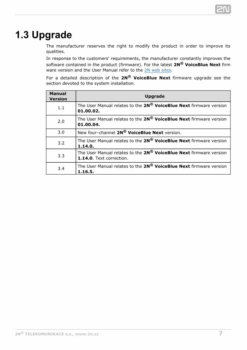
1.3 UpgradeThe manufacturer reserves the right to modify the product in order to improve itsqualities.
In response to the customers' requirements, the manufacturer constantly improves thesoftware contained in the product (firmware). For the latest firm2N VoiceBlue Next®
ware version and the User Manual refer to the .2N web sites
For a detailed description of the firmware upgrade see the2N VoiceBlue Next®
section devoted to the system installation.
ManualVersion
Upgrade
1.1 The User Manual relates to the firmware version 2N VoiceBlue Next®
01.00.02.
2.0 The User Manual relates to the firmware version 2N VoiceBlue Next®
01.00.04.
3.0 New four–channel version.2N VoiceBlue Next®
3.2 The User Manual relates to the 2N VoiceBlue Next® firmware version 1.14.0.
3.3The User Manual relates to the firmware version 2N VoiceBlue Next®
. Text correction.1.14.0
3.4 The User Manual relates to the 2N VoiceBlue Next® firmware version 1.16.5.
82N TELEKOMUNIKACE a.s., www.2n.cz®
1.4 Terms and Symbols Used
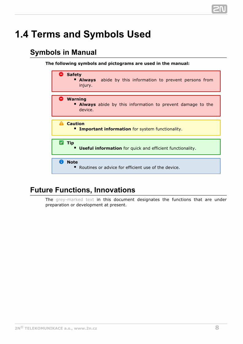
Symbols in ManualThe following symbols and pictograms are used in the manual:
Safety abide by this information to prevent persons fromAlways
injury.
Warning abide by this information to prevent damage to theAlways
device.
CautionImportant information for system functionality.
TipUseful information for quick and efficient functionality.
NoteRoutines or advice for efficient use of the device.
Future Functions, InnovationsThe in this document designates the functions that are undergrey-marked textpreparation or development at present.
92N TELEKOMUNIKACE a.s., www.2n.cz®
2. Description and Installation
This section describes the proper product installation and2N VoiceBlue Next®
connection.
Here is what you can find in this section:
2.1 Before You Start2.2 Factory Settings2.3 Brief Installation Guide2.4 IP Voice Transmission2.5 VoiceBlue Next Connection to VoIP
102N TELEKOMUNIKACE a.s., www.2n.cz®
2.1 Before You StartCaution
Make sure that you are equipped with all system componentsnecessary for putting in operation (SIM2N VoiceBlue Next®
card, VoIP phone and/or duly configured SIP line of your SIPProxy, an available 100BaseT socket and a PC for initialsettings).
Product Completeness CheckBefore installing this product, check whether the delivery2N VoiceBlue Next®
complies with the following packing list. Be careful because there may be differences inthe packing list depending on whether you have ordered a two-channel or four-channelversion of the product (different part numbers).2N VoiceBlue Next®
Package 2ch VBN 4ch VBN
2N VoiceBlue Next® 1 1
Power supply adapter 1 1
Short antenna 1 None
Long antenna 1 1
Ethernet cable 1 1
Quick Start manual 1 1
Wall–mounting set 1 None
SIM card cover including screws 1 None
Rubber feet None 4
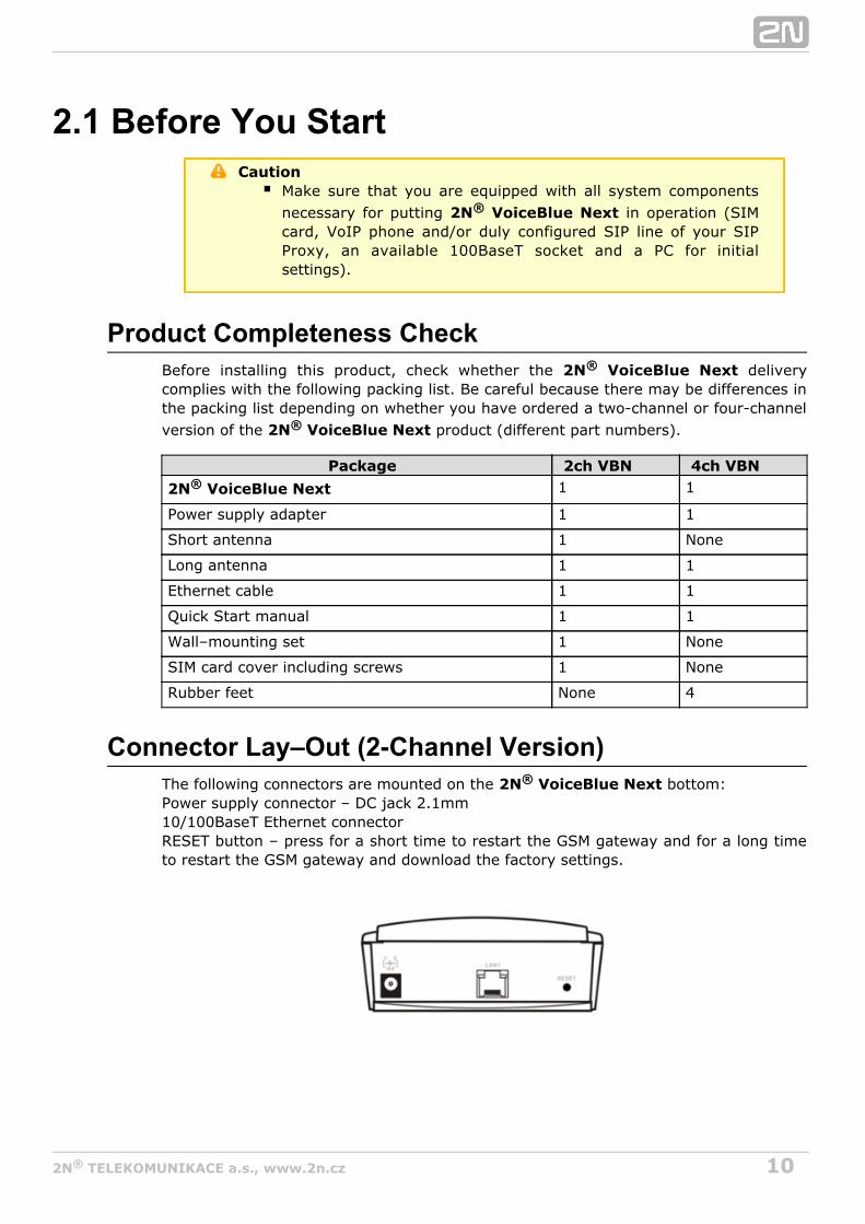
Connector Lay–Out (2-Channel Version)The following connectors are mounted on the bottom:2N VoiceBlue Next®
Power supply connector – DC jack 2.1mm10/100BaseT Ethernet connectorRESET button – press for a short time to restart the GSM gateway and for a long timeto restart the GSM gateway and download the factory settings.

112N TELEKOMUNIKACE a.s., www.2n.cz®
Connector Lay–Out (4-Channel Version)The following connectors are mounted on the bottom:2N VoiceBlue Next®
10/100BaseT Ethernet connector with PoE supportRESET button – press for a short time to restart the GSM gateway and for a longtime to restart the GSM gateway and download the factory settings.Antenna connector for all GSM/UMTS channelsSIM holder
Find a power supply connector (DC Jack 2.1mm) and type plates at the rear.
Status LED IndicatorsThe states are indicated by LEDs on the front and system2N VoiceBlue Next®
connector sides. For the LED types see the table below.

122N TELEKOMUNIKACE a.s., www.2n.cz®
SIM Card Placement (2-Channel Version)Lift off the SIM card holder on the backside, insert the SIM card2N VoiceBlue Next®
and replace the holder, securing the latch.
SIM Card Placement (4-Channel Version)Insert a SIM card into one of the four SIM holders on the front 2N VoiceBlue Next®
making sure that the chip contacts are at the front bottom. The SIM holders areequipped with the push&pull technology for facilitation.

132N TELEKOMUNIKACE a.s., www.2n.cz®
CautionRemember to call forwarding, call barring, preferentialsetnetwork(s), SMS centre and similar provider and SIM cardservices in your mobile phone before inserting the SIM card in .2N VoiceBlue Next®
If two SIM cards are used, both of them must have an, or must be selected.identical PIN PIN request disable
Disconnect 2N VoiceBlue Next® from the power supply before inserting the SIM cards!
Licences2N VoiceBlue Next® may contain time–limited software licences (SIP signalling,Mobility Extension, e.g.) that render services for limited hours only. Every gatewayrestart adds one hour to the internal licence counter. To check the current licencestatus, use the web interface of the gateway (refer to ), or the AT interface ofSubs. 3.4the Telnet protocol (refer to ).S. 4
CautionA GSM gateway with an expired licence cannot process anyincoming and/or outgoing calls! To avoid this, ask your dealerfor licence prolongation or an unlimited licence!
GSM/UMTS Network RestrictionSome types may be restricted to certain GSM/UMTS networks2N VoiceBlue Next®
only. If so, the red indicator at the given GSM/UMTS module is on and the 'netw-err'cause is detected. Contact your dealer please for more information.
TipContact your dealer please for more information.
Potential GSM/UMTS TroublesAll 2N GSM gateways work reliably under a long-time full load. The following problemsmay be caused by GSM/UMTS networks:
GSM/UMTS module(s) cannot log in, log in slowly, or log out occasionally. Thisproblem may be caused by any of the following situations:
The GSM/UMTS signal is low. The minimum signal level should beapproximately . If lower, change the antenna position or type!–80dBmThe GSM/UMTS cell (BTS) to which the GSM/UMTS modules are trying tolog in is overloaded. Change the antenna position or reduce the count ofthe logged-in GSM/UMTS modules.
One of the GSM/UMTS modules is permanently logged-out or fails to makeoutgoing calls:
The problem indicates a GSM/UMTS network overload on the installationsite. To eliminate the problem, set the parameter to Relax delay 2

142N TELEKOMUNIKACE a.s., www.2n.cz®
(refer to the subsection). If the GSMseconds GSM Basic Parametersmodule fails to log in or rejects to make outgoing GSM calls even after thegateway restart, consult your GSM provider for your SIM card/GSM moduleavailability.
The manufacturer shall not be held liable for any SIM card or provider serviceunavailability in the case of a breach of the provider's SIM terms and conditions for theSIM card use.
152N TELEKOMUNIKACE a.s., www.2n.cz®
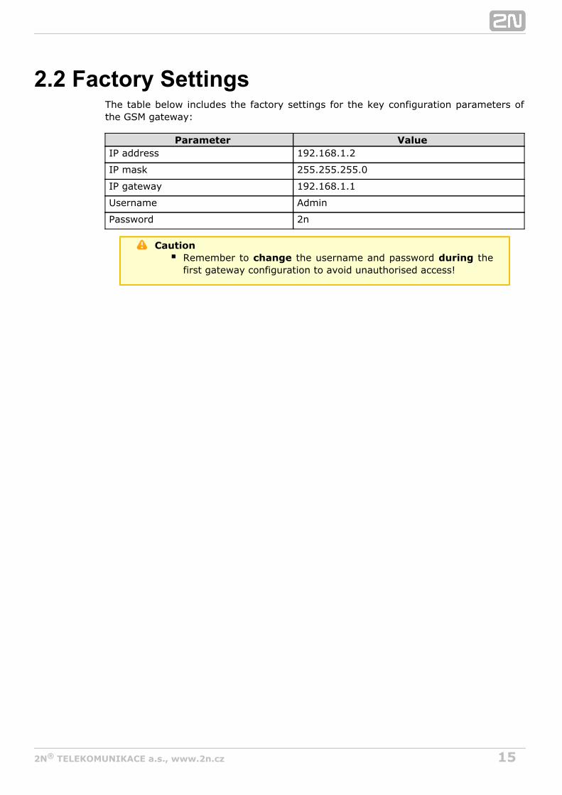
2.2 Factory SettingsThe table below includes the factory settings for the key configuration parameters ofthe GSM gateway:
Parameter ValueIP address 192.168.1.2
IP mask 255.255.255.0
IP gateway 192.168.1.1
Username Admin
Password 2n
CautionRemember to the username and password thechange duringfirst gateway configuration to avoid unauthorised access!

162N TELEKOMUNIKACE a.s., www.2n.cz®
2.3 Brief Installation Guide
SIM Card Inserting/RemovingFor the correct handling of SIM cards refer to the SIM Card Placement subsection.
CautionMake sure that the GSM gateway is off before inserting andremoving SIM cards to avoid the GSM/UMTS module damage.
Installation ConditionsThe following installation conditions have to be met for proper installation:
2N VoiceBlue Next® is to be installed on a site with enough free space.2N VoiceBlue Next® can be mounted on a vertical surface (2-channel version),or on a horizontal surface or into a system rack (4-channel version). It is possibleto operate in another working position too, e.g. on a desk,2N VoiceBlue Next®
for a short time for servicing and testing purposes, for example.Any excess of the allowed working temperature may not affect the 2N®
function immediately but may result in faster ageing and lowerVoiceBlue Next reliability. For the allowed working temperature and humidity ranges refer to S. 52N VoiceBlue Next® is not designed for high–vibration environments such asmeans of transport, machine rooms, and similar.2N VoiceBlue Next® is not designed for dusty environments or places exposedto high humidity and temperature changes.2N VoiceBlue Next® may not be exposed to aggressive gases, acid and solventvapours, and so on.2N VoiceBlue Next® is intended for indoor use. It may not be exposed to rain,flowing water, condensing moisture, fog, and so on.2N VoiceBlue Next® may never be exposed to direct sunshine or placed closeto heat sources (radiators).A sufficient clearance must be kept over and under for 2N VoiceBlue Next®
cabling and air flow to carry off the heat.A sufficient GSM/UMTS signal intensity has to be provided for 2N VoiceBlue®
.NextAn adequate capacity of the GSM/UMTS network has to be ensured (no BTSoverload). Remember that multiple GSM gateways used in one location mayoverload the base transceiver station (BTS) you are currently logged in to. Thismay lead to a permanent or occasional rejection of GSM/UMTS calls!No strong electromagnetic radiation is allowed on the 2N VoiceBlue Next®
installation site.No strong electromagnetic reflections are allowed on the 2N VoiceBlue Next®
antenna installation site.An inappropriate location of or its antenna close to2N VoiceBlue Next®
television, broadcasting and/or other rf-sensitive sets may impair the function ofthese sets.Being a source of radio frequency emissions, the antenna2N VoiceBlue Next®

172N TELEKOMUNIKACE a.s., www.2n.cz®
1.
2.
should not occur in the close vicinity of the human body. The health hazard ishigher than with mobile phones as, generally, gateways shared by multiple usersshow a very high traffic.Make sure that the VoIP connection has been configured properly according tothe SIP and other VoIP recommendations.It is recommended that the power supply adapter should be connected to anetwork with a UPS back-up and due overvoltage protection.
Wall Mounting (2-Channel Version)Follow the instructions below to wall mount :2N VoiceBlue Next®
Drill two screws into the wall in a relative distance matching the wall mountingholes in the rear. 2N VoiceBlue Next® The maximum screw head – wall
distance is 5mm.Hang the unit onto the pre-drilled screws.2N VoiceBlue Next®
CautionDo not open the GSM gateway during wall mounting to avoidproduct damage and subsequent warranty invalidation!The screw head – wall distance must allow for simple handlingsuch as removing from the wall.

182N TELEKOMUNIKACE a.s., www.2n.cz®
1.
2. 3.
1.
Horizontal Mounting (4-Chanel Version)2N VoiceBlue Next® is ready for mounting on a horizontal support. You can stickrubber feet (included in the delivery) on the device if necessary. Follow the instructionsbelow:
Put the GSM gateway carefully on a stable horizontal support with its bottom sideup.Stick the rubber feet into the corners as shown below.Place the device on a stable horizontal support.
cautionRefer to the Proper Location subsection for correct placing!
System Rack Mounting (4-Channel Version)2N VoiceBlue Next® can be mounted into a system rack. Purchase the rackaccessories separately under Part No. . The accessory pack includes the5051099Efollowing components:
Components PiecesShort wing 2
Long wing 1
Rear connecting plate 1
Upper connecting plate 1
Mounting screws 12
Rack screws 4
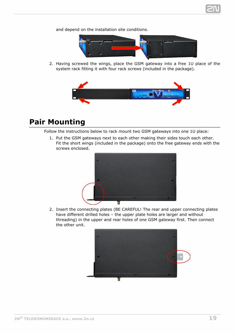
Single MountingFollow the instructions below to mount a single unit into a system rack:
Fit the rack wings to the right and left sides using four screws for each wing(included in the package). The positions of the long and short wings are optional
192N TELEKOMUNIKACE a.s., www.2n.cz®
1.
2.
1.
2.
and depend on the installation site conditions.
Having screwed the wings, place the GSM gateway into a free 1U place of thesystem rack fitting it with four rack screws (included in the package).
Pair MountingFollow the instructions below to rack mount two GSM gateways into one 1U place:
Put the GSM gateways next to each other making their sides touch each other.Fit the short wings (included in the package) onto the free gateway ends with thescrews enclosed.
Insert the connecting plates (BE CAREFUL! The rear and upper connecting plateshave different drilled holes – the upper plate holes are larger and withoutthreading) in the upper and rear holes of one GSM gateway first. Then connectthe other unit.

202N TELEKOMUNIKACE a.s., www.2n.cz®
2.
3. Place the GSM gateway pair into a free 1U place in the system rack and fit it withfour rack screws (included in the package).
CautionThe rear and upper connecting plates have different holes – theupper plate holes are larger and without threading.Make sure that the plate does not get into the device to avoidelectric short-circuit inside the GSM gateway.Leave 2 cm free space at least over and under the GSM gatewayfor better ventilation (airflow)!
Power Supply ConnectionUse only the power supply adapter included, or, with the power over Ethernet, acertified PoE adapter to feed the gateway. Make sure that the electric distributionnetwork voltage is in compliance with the data on the supply adapter plate beforeplugging the adapter. First plug the supply adapter into the mains socket and only thenconnect the adapter connector to the gateway. Refer to the status indicators.
WarningConnecting a defective or inappropriate power supply adaptermay lead to a temporary or permanent 2N VoiceBlue Next®
error!Never connect using the PoE and a local2N VoiceBlue Next®
adapter at the same time to avoid permanent 2N VoiceBlue®
malfunction!NextCheck whether the antenna is connected before plugging theadapter. Feeding the device without antenna connectionmay result in the GSM module transmitter damage.

212N TELEKOMUNIKACE a.s., www.2n.cz®
Antenna Connection2N VoiceBlue Next® is equipped with a SMA female antenna connector for all theGSM/UMTS modules. The external antenna should always be installed vertically on asite with a good wireless signal.
WarningTighten the antenna – connector gently with your hand
!never use a wrenchBeing a source of radio frequency emissions, the 2N®
antenna should not occur in the close vicinity VoiceBlue Nextof the human body. The is higher than withhealth hazardmobile phones as, generally, gateways shared by multiple usersshow a very high traffic.
NoteThe antenna has a sufficient gain for a trouble-free operationunder normal conditions. If the signal is poor or you want toplace your antenna separately from , you2N VoiceBlue Next®
can use an antenna with an SMA–connector terminated cable.The antenna should be mounted vertically.Refer to the section for the antenna andTechnical Parameterscable parameters.
Ethernet Cable ConnectionTo connect into an Ethernet network use a standard straight2N VoiceBlue Next®
cable terminated with RJ–45 connectors (included in the package). The GSM gatewaysupports the 10BaseT and 100BaseT standards, the Ethernet connection status isindicated by the status LED indicators located on the RJ–45 connector (refer to Subs.
for details).2.1For the Ethernet interface factory settings for refer to .2N VoiceBlue Next® Subs. 2.2
CautionResetting factory values results in a change of the 2N®
Ethernet interface configuration! VoiceBlue NextUsing a defective Ethernet cable may lead to a high packet lossrate in the Ethernet network and subsequent instability and poorquality of all GSM/UMTS calls!

222N TELEKOMUNIKACE a.s., www.2n.cz®
RJ–45 connector for LAN connection
Antenna SplitterThe antenna splitter is a passive component that combines multiple GSM/UMTSchannels into one antenna. In , it combines two/four antennae2N VoiceBlue Next®
into one. The antenna splitter is placed in the installation box. It is a passive element –it has a characteristic signal attenuation value that the antenna connected mustcompensate. No antenna splitter is used for one-channel gatewa2N VoiceBlue Next®
ys.
Licence Restrictions2N VoiceBlue Next® may contain time limited software licences. See p. for moreinformation.
Firmware UpgradePlease upgrade the firmware before installing the system. Check2N VoiceBlue Next®
the web sites for the latest firmware for this gateway type.www.2N.cz
WarningUse the for this gateway type only! Anyfirmware certifiedother firmware type may damage 2N VoiceBlue Next®
!irreversibly
Follow the instructions below to download firmware easily using the gateway webinterface:
Connect your PC and the gateway into the Ethernet network.Open the web browser (MS Internet Explorer 9 and higher or Mozzila Firefox 4and higher are recommended).Enter the to register at the web interface.http://IP_addressClick on , then on and select theManagement–>Firmware update Browsenew firmware file.Click on the icon in the lower part of the web page.Download firmware2N VoiceBlue Next® will upgrade the firmware automatically.

232N TELEKOMUNIKACE a.s., www.2n.cz®
2.4 IP Voice Transmission
Speech Encoding MethodsVoice transmission is strictly separated from signalling in VoIP networks. Modern VoIPnetworks mostly use the RTP (Realtime Transport Protocol) for voice transmission. Thepurpose of the RTP is only to transmit data (voice) from a source to a destination atreal time. Codecs are used to save the channel data capacity. Codecs process the voicesignal using variable algorithms to minimise the volume of user data. The degree ofcompression used by the codec affects the quality of voice transmission. Thus, thebetter voice transmission is required, the wider data range (the higher transmissionrate) is needed. The MOS (Mean Opinion Score) scale is used for rating voicetransmission quality, where 1 means the worst and 5 the best quality. For a survey ofthe codecs supported by refer to the table below.2N VoiceBlue Next®
Codecs supported
Standard Algorithm Transmission rate [kbps] MOSG.711a PCM 64 4.1
G.711u PCM 64 4.1
G.729* CS–ACELP 8 3.92
[*] G.729 is an optional part of the system.
For , quadruple the above mentioned rates (two fully duplex 2N VoiceBlue Next®
calls) and add the TCP and IP header transmission rate to the result to get theresultant transmission rate.It is important to keep both a stable appropriate transmission rate during connectionand a small and identical transmission time per data packet in order to maintain ahigh-quality voice transmission.
G.711 – this codec is used in digital telephone networks. The PCM (Pulse CodeModulation) is used for voice signal encoding. The sampled signal is encoded in12 bits and then compressed using a non-linear scheme into the resultant 8 bits.Europe uses the A–law compression system while North America and Japan obeythe µ-law. The resultant data flow is 64 kbps.G.729 – this codec uses the CS–ACELP (Conjugate-StructureAlgebraic-Code-Excited Linear-Prediction) algorithm with the resultanttransmission rate of 8 kbps. The speech signal is split into blocks of 10 ms each.The parameters of these blocks are then inserted in frames of the size of 10bytes. 2–byte frames are generated for noise transmission.
During call set-up, a codec is selected automatically for voice transmission. 2N®
supports the codecs included in the table above. The type of codec toVoiceBlue Nextbe used depends on your VoIP network (individual devices) and your 2N VoiceBlue®
configuration. is designed primarily for VoIP corporateNext 2N VoiceBlue Next®
networks and tries to meet the opponent's codec requirements. If a codec is requestedthat is incompatible with , the call will be rejected.2N VoiceBlue Next®
The SIP and ITU–T H.323 recommended protocols are mostly used for connectionestablishing, maintaining and cancelling. uses the (Session2N VoiceBlue Next® SIP

242N TELEKOMUNIKACE a.s., www.2n.cz®
Initiation Protocol) signalling.
TipIn the case of separated direct connection of your SIP Proxy and
, use the G.711 codec to achieve a high2N VoiceBlue Next®
voice quality.
SIP ComponentsThe following components are involved in the SIP message exchange:
UAC (User Agent Client) – the terminal device client, which initiates SIPsignalling.UAS (User Agent Server) – the terminal device server, which responds to SIPsignalling from the UAC.UA (User Agent) – a SIP network terminal (SIP phones, gateways to othernetworks, etc.), which contains the UAC and UAS.Proxy server – receives connection requests from the UA and transfers them tothe next Proxy server if the given station is not under it administration.Redirect server – receives connection requests, but, instead of sending them tothe called line, sends them back to the requesting device asking for where toroute the request.Location server – receives registration requests from the UA and updates theterminal database accordingly.
All the server components (Proxy, Redirect, Location) are mostly on one physicaldevice called Proxy server, which is responsible for keeping a client database andconnection establishing, maintaining and terminating, as well as call routing.The VoIP–GSM gateway acts as a UA in any case (has the same 2N VoiceBlue Next®
functions as a VoIP phone), i.e. receives call set-up requirements and, on the basis ofits inner LCR table, routes calls to GSM networks.None of the SIP–defined server components are integrated in the 2N VoiceBlue®
gateway.Next
SIP Signalling MessagesBelow is a list of messages sent via the SIP:
INVITE – connection set-up request;ACK – INVITE confirmation by the final message addressee;BYE – connection termination;CANCEL – failed connection cancellation;REGISTER – UA registration with the SIP Proxy;OPTIONS – server capability query.
The answers to the SIP messages are numerically coded as the case is with the httpprotocol. Below are the most important ones:
1XX – information messages (100 – trying, 180 – ringing, 183 – progress);2XX – successful request completion (200 – OK);3XX – request forwarding needed (302 – temporarily moved, 305 – use Proxy);4XX – error (403 – forbidden, 486 – busy here);5XX – server error (500 – Server Internal Error, 501 – not implemented);
262N TELEKOMUNIKACE a.s., www.2n.cz®
2.5 VoiceBlue Next Connection to VoIPSince communicates using the SIP only, this subsection outlines2N VoiceBlue Next®
solutions for its interconnection with networks working with the H.323 signallingprotocols. can be used either in the Point-to-Point or2N VoiceBlue Next®
Point-to-Multipoint mode with the SIP Proxy server.
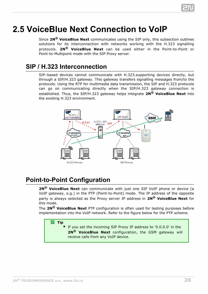
SIP / H.323 InterconnectionSIP–based devices cannot communicate with H.323.supporting devices directly, butthrough a SIP/H.323 gateway. This gateway transfers signalling messages from/to theprotocols. Using the RTP for multimedia data transmission, the SIP and H.323 protocolscan go on communicating directly when the SIP/H.323 gateway connection isestablished. Thus, the SIP/H.323 gateway helps integrate into2N VoiceBlue Next®
the existing H.323 environment.
Point-to-Point Configuration2N VoiceBlue Next® can communicate with just one SIP VoIP phone or device (aVoIP gateway, e.g.) in the PTP (Point-to-Point) mode. The IP address of the oppositeparty is always selected as the Proxy server IP address in for2N VoiceBlue Next®
this mode.The PTP configuration is often used for testing purposes before2N VoiceBlue Next®
implementation into the VoIP network. Refer to the figure below for the PTP scheme.
TipIf you set the incoming SIP Proxy IP address to '0.0.0.0' in the
configuration, the GSM gateway will2N VoiceBlue Next®
receive calls from any VoIP device.

272N TELEKOMUNIKACE a.s., www.2n.cz®
All calls outbound to GSM are routed to the gateway in the2N VoiceBlue Next®
Point-to-Point mode that uses .2N VoiceBlue Next®
Point-to-Multipoint ConfigurationPoint-to-Multipoint is a classical scheme of a distributed VoIP network with one or moreSIP Proxy servers (VoIP gateway). The SIP Proxy server is a software PBX (or astandard PBX extended with VoIP services), which is responsible for all VoIP signalling.Multiple source devices (VoIP phones, e.g.) and multiple target devices (2N®
, e.g.) can be used in this mode. An internal routing algorithm (LeastVoiceBlue NextCost Router, LCR) of your SIP Proxy is used for routing outgoing GSM and other calls inthis mode. Calls to GSM networks can be routed via the gateway2N VoiceBlue Next®
s. All SIP signalling is governed by the SIP Proxy server and the subsequent voicestream is based on the Point-to-Point RTP.
282N TELEKOMUNIKACE a.s., www.2n.cz®
3. VoiceBlue NextConfiguration
This section describes the configuration.2N VoiceBlue Next®
Here is what you can find in this section:
3.1 Factory Reset3.2 Basic Configuration – Step by Step3.3 Call Routing3.4 Web Configuration Interface
Gateway controlGateway configurationMessaging
SMPP Basic Configuration – Step by StepSMTP/POP3 Basic Configuration – Step by Step
MonitoringList of SNMP traps
Others
292N TELEKOMUNIKACE a.s., www.2n.cz®
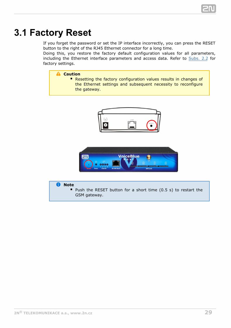
3.1 Factory ResetIf you forget the password or set the IP interface incorrectly, you can press the RESETbutton to the right of the RJ45 Ethernet connector for a long time.Doing this, you restore the factory default configuration values for all parameters,including the Ethernet interface parameters and access data. Refer to forSubs. 2.2factory settings.
CautionResetting the factory configuration values results in changes ofthe Ethernet settings and subsequent necessity to reconfigurethe gateway.
NotePush the RESET button for a short time (0.5 s) to restart theGSM gateway.

302N TELEKOMUNIKACE a.s., www.2n.cz®
3.2 Basic Configuration – Step by StepThis section will help put your gateway in operation for the first2N VoiceBlue Next®
time. Refer to all subsections for detailed settings.S. 3
Install the GSM gateway as instructed in Before the first start, removeSubs. 2.3.the SIM cards, or insert the SIM cards with the PIN request disable.Connect the GSM gateway to the Ethernet network to enable connection to theaddress mentioned in from the configuration terminal. If the gatewaySubs. 2.2default IP address is not suitable for your Ethernet installation, reset the IPaddress as follows:
Disconnect the configuration terminal from the Ethernet network.Disconnect the GSM gateway from the Ethernet network.Prepare the Ethernet switches, or an Ethernet crossed cable.With the Ethernet crossed cable, interconnect the configuration terminalwith the GSM gateway directly.With the Ethernet switch, connect the configuration terminal and GSMgateway to the pre–prepared Ethernet switch. We do not recommendconnecting any other equipment.Change the Ethernet IP setting in the configuration terminal, e.g.:IP=192.168.1.200, Net Mask: 255.255.255.0.Open your web browser and enter the GSM gateway IP address.Enter the factory login data.Change the required settings in the Gateway configuration, Ethernet
menu and store the data into the GSM gateway.configurationConnect the GSM gateway to a standard Ethernet network.Restore the configuration terminal IP setting and connect the configurationterminal to a standard Ethernet network.
Enter the new GSM gateway IP address to get connected to the web interface.Enter the current time and date in the menu forGateway control, Date/Timethe GSM gateway.Make sure that the item is in the Licence status unlocked Gateway control,
menu. If not, your GSM gateway does not contain theFirmware/Licencelicence. Contact your dealer for the licence key.Set the correct PIN value in the Gateway configuration, System parametersmenu. The value must comply with the SIM card PIN value.Set new login data in the menu.Gateway configuration, Login configurationSwitch the GSM gateway off and insert the SIM cards. Connect an antenna to theGSM gateway and switch it on.The GSM gateway contains the factory configuration settings that enableoutgoing calls without additional settings. Now enter the IP address equal to theGSM gateway IP address on your SIP Proxy or IP terminal.
From now on, will be ready to receive VoIP–SIP calls and route2N VoiceBlue Next®
them to GSM/UMTS networks. If all the GSM modules are occupied, or logged out, theGSM gateway will reject all VoIP–IP and GSM/UMTS calls.Should you get in troubles, follow the steps below please:
Read the User Manual carefully and check all parameters.Find answers to the frequently asked questions at .http://faq.2n.czConsult your servicing partner.
You are recommended to attend a certified training to improve your installation2N®
chances.

322N TELEKOMUNIKACE a.s., www.2n.cz®
3.3 Call RoutingCalls from a VoIP port to a GSM/UMTS network are routed to any GSM/UMTS portaccording to the LCR (Least Cost Routing) table. If an incoming call is routed via a busyport, other ports are checked automatically for availability (depending on theconfiguration) and in case no allowed outgoing port is available, the outgoing call isrejected.
The LCR algorithm identifies the outgoing call type, current time tariff rate, day in aweek, and/or free minutes of GSM providers and routes outgoing calls accordingly.
Incoming calls from GSM networks are routed directly to the defined SIP address, orthe DISA function is activated. Furthermore, calls can be routed according to the CLIP(caller's telephone number). And the CallBack service is also available.
Mobility ExtensionMobility Extension (ME) is a function that turns your mobile phone into a fixed officeline and thus helps you take advantage of all PBX functions.Advantages:
You never miss any important call as you are available at all times.You can get information SMS messages on missed calls.You can control your company PBX call forwarding services from your mobilephone.You can make use of a comfortable DTMF code control.You need not make complicated forwarding actions as the function is fullyautomatic.ME can work with any SIP Proxy PBX.ME can replace any standard VoIP phone.Calls to your mobile phone are free of charge or at a moderate cost .4
You need not integrate a costly DECT system any longer.
Model Situation:“Follow me” function
Figure 1: Follow Me Function
Fig. 1 shows routing of calls in the case of absence of a subscriber in the VoIP network.Subscriber A calls subscriber B, for whom the Mobility Extension function has been

332N TELEKOMUNIKACE a.s., www.2n.cz®
permitted with the active “Follow me” function. Subscriber B does not answer the callin the VoIP network and so the call is rerouted to its mobile telephone.
“SMS at no answer” function
In the case of a missed call in the VoIP network, the Mobility Extension providessending of an information text announcement. This function is called “SMS at noanswer”. Like with call forwarding, it is possible to use the DTMF option to activate anddeactivate the service of sending text announcements for missed calls.
Figure 2: SMS at No Answer Function
Fig. 2 shows sending of information texts if an incoming call is not answered.Subscriber A calls subscriber B, for whom the Mobility Extension has been permittedwith activated “Follow me” and “SMS at no answer” services. Subscriber B does notanswer the call in the VoIP network and so the call is rerouted to its mobile telephone.Subscriber B does not answer the mobile phone call and is sent a text announcing thatthe call from subscriber A has been missed.
Call forwarding function
In addition to rerouting calls in the event of absence, the Mobility Extension allows callsto be forwarded within a VoIP network, which brings the services of the SIP Proxy toa mobile telephone. The description of this function is shown in Fig. 3.
Figure 3: Call Forwarding Function

342N TELEKOMUNIKACE a.s., www.2n.cz®
In Fig. 3 subscriber A is talking to subscriber B, for whom the Mobility Extension hasbeen permitted. Subscriber A would like to be forwarded to subscriber C. For thisreason, subscriber B holds the call with A (7* in the default setting ), dials the numberof subscriber C, terminates dialling with the dialling end character (# in the defaultsetting), notifies subscriber C of the call to be forwarded and hangs up to forward thecall. If subscriber C does not want to talk to subscriber A, subscriber B terminates thecall with C (9# in the default setting) and returns to the call with A.
Quick call forwarding function
In Fig. 4 subscriber A is talking to subscriber B, for whom the Mobility Extension hasbeen permitted. Subscriber A would like to be forwarded to subscriber C. Subscriber Bwants to forward the call without having to talk to subscriber C. So subscriber Bputs the call with A on hold (7* in the default setting), dials the quick forwardingcharacter (default value #) and dials the telephone number of subscriber C,terminating the dialling with the dialling end character (default value #). Havingreceived the dialling end character, terminates the call between2N VoiceBlue Next®
A and B and attempts to make a call between subscribers A and C. Subscriber A thenreceives the ring tone.
Figure 4: Quick Call Forwarding Function
Correct ME configuration:
Connect the GSM gateway to your PBX/SIP Proxy.Check whether the Mobility Extension licence key has been entered correctly.Enter all ME users in the menu.Gateway configuration - Mobility ExtensionEnter the prefix matching the ME user mobile number in the Gateway
menu.configuration - prefixes

352N TELEKOMUNIKACE a.s., www.2n.cz®
LCR TableThe LCR (Least Cost Routing) table is the key telephone cost cutting factor. It helpsyou select call routes according to the called subscriber's number and the day time andweekdays. By adding bank holidays to the LCR table you achieve even higher call costsavings.To make your prefix and LCR routing work properly, enter the prefix and the totalcount of digits for the number to be dialled to a GSM/UMTS network in the List of
. Furthermore, make sure that the SIM card of the provider consistent withnetworksthe defined group has been inserted in the GSM gateway. Use the Assignment to
table to assign outgoing and incoming calls to groups.GSM groupsWhenever a call is to be set up, the LCR table is searched sequentially from top tobottom. If the called destination prefix matches the network prefix included in the List
table (and designated as in the LCR table), the call isof networks Network numberrouted according to the routing group parameters ( in the LCR table) as set inGroupsthe table. The call will be connected via the GSM module asGSM outgoing groupsassigned to the in the table.GSM outgoing group Assignment to GSM groupsIf the selected GSM/UMTS module is busy, the call is routed according to the nextrouting rule in the as defined by the table. Again, theGroups GSM outgoing groupsGSM outgoing group is assigned to a GSM module in the Assignment to GSM groupstable.The LCR row is checked in this way until a free GSM/UMTS module is found. If noavailable GSM/UMTS module ( ) is found, the call is rejected.GSM outgoing groups
Routing Algorithm for Outgoing CallsThe GSM/UMTS outgoing call routing algorithm is launched whenever the SIP Proxyroutes an outgoing call to . Outgoing calls are routed via 2N VoiceBlue Next® 2N®
as follows:VoiceBlue Next
The calling subscriber dials the subscriber number and the SIP Proxy routes it to depending on the SIP Proxy settings.2N VoiceBlue Next®
The number prefix is checked against the prefixes in the tablesList of networksin the ascending sequence, i.e. table 1 is searched first, followed by table 2 andso on.When a matching prefix is found in a , the LCR is checked for aList of networksvalid row. Again, the LCR is searched upwardly, starting from the first row.If a number matches a valid number on the respective row,List of networksthe call time is checked against the routing rule. If no match is found, the nextLCR row is checked.If the number and call time meet the routing rules, the call isList of networksrouted to the module selected in the tableAssignment to GSM groupsaccording to the first routing rule included in the section and given in theGroups
table.GSM outgoing groupsMoreover, call duration limiting timer can be selected for the outgoing call.If the selected GSM/UMTS module is occupied or has a low credit, the algorithmreturns to the preceding step but considers the next row instead of theGroupsfirst one. If no record is found in this section, the next LCR row is used.If the selected GSM/UMTS module is available and has a sufficient credit, theGSM gateway will start dialling the GSM number.If the calling subscriber number has an unknown prefix or all routes are

362N TELEKOMUNIKACE a.s., www.2n.cz®
occupied, rejects the connection request.2N VoiceBlue Next®
The outgoing call is not billed until the called party answers the call.The GSM network signals the call answering moment and the GSM gatewaytransfers this information to the SIP Proxy.It can be set for GSM outgoing calls that the calling subscriber should be sent theconnection tone* instead of a silence between the request sending to GSM andthe ringing tone.
* This option can be activated for TC35i modules.
Routing Algorithm for Incoming CallsIncoming calls are processed according to the parameter setting in the Mode GSM
table. The following options are available:incoming groups
Reject/ Ignore incoming calls – incoming calls are not routed to the VoIPnetwork. On the GSM side, the connection request is either rejected or ignored(the caller hears the check ringing tone).If the above mentioned option is not selected, the CLIP routing table is checked.If the calling number is found, it is checked for CallBack first. If the CallBackfunction is enabled for this number, will ignore the2N VoiceBlue Next®
incoming call and set up a CallBack to GSM after the caller hangs up. If theAutoDial function is enabled for the calling number, the caller will be routeddirectly to the extension number entered in the AutoDial item. If both theCallBack and AutoDial functions are activated, will ignore2N VoiceBlue Next®
the incoming call and set up a call to GSM after the caller hangs up.Simultaneously, a call to the VoIP extension will be set up and then the calls willbe connected. If the CallBack function is enabled and the caller fails to hang upwithin 10 s, will try to set up a call according to the2N VoiceBlue Next®
AutoDial settings.In case the CLIP routing function is disabled or the calling number is not includedin the CLIP routing table, the Dynamic CLIP routing table is checked. If thecalling number is found, the incoming call is routed directly to the correspondingextension. To set the Dynamic CLIP routing function use the GSM incoming
menugroups .If the incoming call is still not processed, the gateway will receive the call andsend either a voice message or the dialtone to the caller. After that, 2N®
awaits the required count of digits necessary for connectionVoiceBlue Nextset-up. Set the minimum and maximum counts of DTMF digits in the GSM
menu.incoming groupsIf does not receive the minimum count of digits and no2N VoiceBlue Next®
other digit comes within the timeout set in the DTMF dialling timeoutparameter, the call is forwarded to the operator as if the called extension numberwere unknown.If call forwarding to the operator is inactive, the incoming call will be rejected.

372N TELEKOMUNIKACE a.s., www.2n.cz®
DISA Welcome NoteIf the DISA service is active and a welcome note has been recorded, the welcome noteis played to every incoming call whose number is not included in the CLIP table orforwarded according to the Dynamic CLIP routing table. When the welcome note hasbeen played, the gateway waits for the first DTMF digit for the period set in the GSM
table. Having received the count of digitsincoming groups – DTMF dialling timeoutincluded in the table, theGSM incoming groups Minimum count of DTMF digitsgateway will set up connection to the SIP Proxy. Use the GSM gateway web interface toupload the DISA welcome note.

382N TELEKOMUNIKACE a.s., www.2n.cz®
3.4 Web Configuration Interface
Essential DataThe web interface supports the following web browsers:2N VoiceBlue Next®
MS Internet Explorer v9Mozilla Firefox v4 and higher
Any other web browsers may cause troubles. The recommended screen resolution is1280x1024 and colour quality 32bit or higher. The configuration interface is available inthe English language version only at present.
TipUse the F11 key to activate the full–screen mode for betterresolution.
LoginFor login to the web configuration interface, enter the server IP2N VoiceBlue Next®
address into your web browser. The following login dialogue will get displayed.
Just one user may be logged in at a time. Refer to for details on the loginSubs. 2.2factory settings.
TipThe user limitation applies to the web interface access only. Theaccess to the Telnet interface is limited to ten simultaneoususers.
A login timeout is set automatically and recovered automatically uponthree-minuteevery user activity on the web interface. After this timeout, the current user is loggedout automatically. Click on the button to reset the maximum timeout value.RefreshSet the login timeout value in the sectioGateway–Web configuration–Auto logoutn.
392N TELEKOMUNIKACE a.s., www.2n.cz®
CautionYou are recommended to change the initial login data upon yourfirst login to considerably increase your system security.
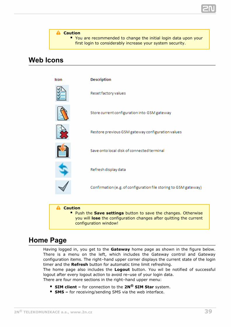
Web Icons
CautionPush the button to save the changes. OtherwiseSave settingsyou will the configuration changes after quitting the currentloseconfiguration window!
Home PageHaving logged in, you get to the home page as shown in the figure below.GatewayThere is a menu on the left, which includes the Gateway control and Gatewayconfiguration items. The right–hand upper corner displays the current state of the logintimer and the button for automatic time limit refreshing.RefreshThe home page also includes the button. You wil be notified of successfulLogoutlogout after every logout action to avoid re–use of your login data.There are four more sections in the right–hand upper menu:
SIM client – for connection to the system.2N SIM Star®
SMS – for receiving/sending SMS via the web interface.

402N TELEKOMUNIKACE a.s., www.2n.cz®
Messaging – for receiving/sending SMS via SMPP or SMTP/POP3Monitoring – for gateway monitoring via SNMPUtils – including extending system tools (Network capture, Report capture).Management – for firmware update, license upload and configurationupload/download.
The main window displays information on the gateway licence status, firmware andbootware versions and the Ethernet interface MAC address. In2N VoiceBlue Next®
addition, you can download a new licence here.

412N TELEKOMUNIKACE a.s., www.2n.cz®
Gateway controlThis group helps:
Monitor the current statuses of the GSM gateway components;Check and set the GSM gateway licence;View and save LOG files and CDR.
Firmware / LicenceThis window provides information on the gateway licensing, firmware and bootwareversions and Ethernet interface MAC address. A new licence code can be inserted here.
Firmware version – current firmware version of the gateway connected.Bootware version – current bootware version of the gateway connected.MAC address – Ethernet interface MAC address of the gateway connected.CPU serial number – GSM gateway serial number in the formatM202–xxxxxxxxxxActive: licensed protocols:
SIP – SIP support;MEx – Mobility Extension support, 'x' gives the maximum count of users;G729 – G.729ab voice codec support;TUN – GSM–CSD remote supervision support.SMSU – count of SMS users.SMSS – SMPP support.SMSE – SMS@email support.SMSW – SMS via web support.SNMP – SNMP monitoring support.
Gateway limitation – gateway operation time (licence limitation if any).Licence status – current licence status (unblocked/blocked).
CautionThe licensed protocols will be blocked when the licence code hasexpired!
Networks – list of allowed/barred GSM/UMTS networks.
TipUpon the dealer's request, the gateway may contain blocking ofcertain GSM/UMTS networks. This state is indicated by a redshining Ch 1 / Ch 2 LED. The GSM module diagnostic windowdisplays the 'netw–err' status.Contact your dealer for more information please.
Licence key for gateway – item for entering a new gateway connecting licence.
CautionBy entering a new licence code you restart the GSM gatewayand discontinue all current calls!

422N TELEKOMUNIKACE a.s., www.2n.cz®
Date / TimeThe Date / Time window enables you to set the current date and time for the gateway.Select the item and the and items will be setSynchronise with local PC Time Dateautomatically according to your PC data.
CautionThe internal back–up source is able to back up the internal clocksource for a few hours only! Make sure that the gateway dateand time values are correct after a long disconnection from thepower supply!
Voice MessagesThis window is used for recording, checking and downloading voicemessages. Supported format is PCM–Alaw, Mono, 8000 Hz, 8 bits.
Index Type of message Use Max. length(s)
0 DISA message Inc. calls from GSM/UMTS 64
1 ME "Hallo" Mobility Extension calls 4
2 ME"Mobility extension" Mobility Extension calls 43 ME"Please dial number" Mobility Extension calls 44 ME"Text message" Mobility Extension calls 45 ME"Activated" Mobility Extension calls 46 ME"Deactivated" Mobility Extension calls 47 ME"beeep" Mobility Extension calls 48 ME"be,be,be" Mobility Extension calls 4
21 GSM outgoing group 1 Calls via Out. GSM group 1 8
22 GSM outgoing group 2 Calls via Out. GSM group 2 8
23 GSM outgoing group 3 Calls via Out. GSM group 3 8
24 GSM outgoing group 4 Calls via Out. GSM group 4 8
25 GSM outgoing group 5 Calls via Out. GSM group 5 8
26 GSM outgoing group 6 Calls via Out. GSM group 6 8
27 GSM outgoing group 7 Calls via Out. GSM group 7 8
28 GSM outgoing group 8 Calls via Out. GSM group 8 8
30 Message 30 Voice message detector 831 Message 31 Voice message detector 832 Message 32 Voice message detector 833 Message 33 Voice message detector 834 Message 34 Voice message detector 835 Message 35 Voice message detector 836 Message 36 Voice message detector 837 Message 37 Voice message detector 8
You can choose which message will be uploaded or use detection by filename. Detection requires file name: "mess[index of message][optional
432N TELEKOMUNIKACE a.s., www.2n.cz®
remark].wav". You can upload more than one message in .tar file.
NoteVoice messages with indexes 30 – 37 are used for detection ofthe mobile provider's voice message played before callconnection. If a match is found of the voice message with any ofthe voice messages recorded in the gateway, the call isterminated automatically or established via the last GSMoutgoing group set in the LCR table (on condition that the ITD –Ignore tone detection in last group parameter is active) in the
section. Refer to theGateway Configuration–>LCR table Gateway Configuration–>GSM basic parameters–>Voice
for details.message detector settings
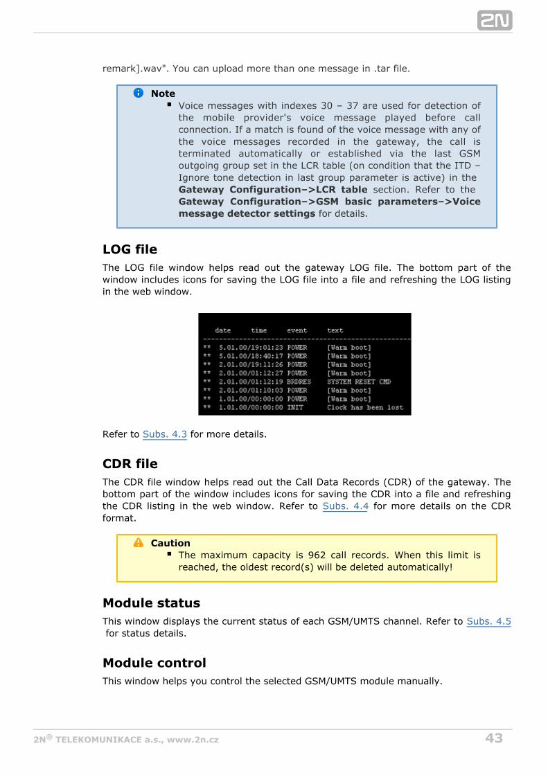
LOG fileThe LOG file window helps read out the gateway LOG file. The bottom part of thewindow includes icons for saving the LOG file into a file and refreshing the LOG listingin the web window.
Refer to for more details.Subs. 4.3
CDR fileThe CDR file window helps read out the Call Data Records (CDR) of the gateway. Thebottom part of the window includes icons for saving the CDR into a file and refreshingthe CDR listing in the web window. Refer to for more details on the CDRSubs. 4.4format.
CautionThe maximum capacity is 962 call records. When this limit isreached, the oldest record(s) will be deleted automatically!
Module statusThis window displays the current status of each GSM/UMTS channel. Refer to Subs. 4.5 for status details.
Module controlThis window helps you control the selected GSM/UMTS module manually.

442N TELEKOMUNIKACE a.s., www.2n.cz®
StatisticsThe window displays the current statistics on calls. The bottom part of the windowincludes icons for saving the LOG file into a file and refreshing the CDR listing in theweb window. Refer to for format information. Subs. 4.6
Current call infoThe window displays the currently made calls. The bottom part of the window includesicons for saving the LOG file into a file and refreshing the listing in the web window.
Connection stateThe window displays the states of all available configuration sessions. The bottom partof the window includes icons for saving the LOG file into a file and refreshing the listingin the web window.
AutoCLIP routing tableThe window displays the current state of the AutoCLIP table. The bottom part of thewindow includes icons for saving the LOG file into a file and refreshing the listing in theweb window.
NoteThe maximum AutoCLIP routing table capacity is 128 records.
SIP registrationThe window displays the current SIP registration state of the gateway.
Online reportThe window displays on–line gateway tracing.
452N TELEKOMUNIKACE a.s., www.2n.cz®
Gateway configuration
System parameters
GeneralSaving call data (CDR) – select the call types on which records are to be savedinto the CDR file.Gateway ID – identifies numerically in the CDR in case2N VoiceBlue Next®
multiple devices generate the CDR in the network.
Summer / winter timeAutomatically switch to summer/winter time – enable an automatic change of thegateway system time at the time of transition to/from the daylight saving time.Date of switch to winter time [dd.mm] – transition day and month.Date of switch to summer time [dd.mm] – transition day and month.
Mobility Extension (DTMF settings)Start dialling (quick call forwarding) – DTMF code for quick forwarding start.End dialling (quick call forwarding) – DTMF code for quick forwarding end.Hold call – DTMF code for active call holding.Hang up call – DTMF code for call termination.Follow me activation – activation of the function. The GSM gatewayFollow mestarts routing call to the defined GSM/UMTS subscriber number. The defaultvalue is *55.Follow me deactivation – deactivation of the function. The defaultFollow mevalue is #55.SMS at no answer activation – activation of the function for aSMS at no answerregistered user. The default value is *33.SMS at no answer deactivation – deactivation of the functionSMS at no answerfor a registered user. The default value is #33.
TipThe and functions can beSMS at no answer Follow meenabled/disabled using the above mentioned DTMF codes bycalling the GSM gateway from a registered mobile user phone.The values of these functions can be changed using theconfiguration interface too (see below).
OthersPIN – PIN code for the SIM cards that request the PIN code.
CautionA SIM card with a PIN code other than that set in the GSMgateway configuration will be blocked with the 'pin-err' cause.To unblock the so-rejected SIM card, enter the correct PIN onyour mobile phone!

462N TELEKOMUNIKACE a.s., www.2n.cz®
End of dialling (empty=off) – a selectable DTMF code for DTMF dialling end in theevent of a DISA incoming call. The default value is '#'.
VoIP parameters
VoIP functionsDay of deleting statistics on VoIP (every month) – the day of automatic deletionof call statistics on the VoIP interface. None = no deletion.
SIP protocol settingsUse CLIP from INVITE field – the CLIP as set in the or field will beContact Fromused for routing calls into GSM/UMTS networks.Send 180 ringing instead of 183 session progress.Send 200 OK instead of 180/183.Send 200 OK and BYE when rejected from GSM.Send 200 OK on REGISTER request – virtual registration of the device in 2N®
(necessary for registration–requiring equipment). VoiceBlue NextReplace CLIP from GSM with Caller ID.Deny DTMF according to RFC2833.Forward DTMF for ME (Mobility Extension).
SIP registration
Registration expires [s] – the timeout after which the 2N VoiceBlue Next®
registration data expire at the SIP Proxy.Reattempt registration [s] – time interval for re-sending the request.Registration domain (realm).Caller ID.Username – registration data for the SIP Proxy.Password – registration data for the SIP Proxy.
Voice parametersFirst RTP port (even: 1024 – 65524) – number of the first RTP port. The numbermust be even as recommended.Last RTP port (even: first RTP+10 – 65534) – number of the last RTP port. Thenumber must be even as recommended. The recommended minimum range ofRTP ports should be 10.
Codec settingsdetailed codec settings (G.711a/u, or G.729).
Codec priority preferential speech codec setting:
Priority 1Priority 2Priority 3
472N TELEKOMUNIKACE a.s., www.2n.cz®
IP addresses
SIP Proxy (IP–>GSM) IP address of the SIP Proxy from which – 2N VoiceBlue®
awaits the GSM outgoing call requirements.Next
TipIn case you keep the default values (0.0.0.0), 2N VoiceBlue®
will receive requests from any IP address.Next
SIP Proxy (GSM–>IP) – IP address of the SIP Proxy to which 2N VoiceBlue®
turns in the case of a GSM incoming call.NextSIP registrar – IP address of the SIP registration server.
TipYou can use the domain name Registration domain (realm)for the , andSIP proxy (IP–>GSM) SIP proxy (GSM–>IP)
IP addresses on condition that you complete theSIP registrardomain name and set the Registration domain (realm) DNS
properly in the server address Websection.The configuration–>Ethernet configuration SIP
and IP addresses must be set to theproxy SIP registrar default value (0.0.0.0).
NAT firewall – IP address for the NAT firewall.STUN server – IP address of the STUN (Simple Traversal of UDP through NATs(Network Address Translation)) server for obtaining the public IP address underwhich operates in the Internet network. You are advised to2N VoiceBlue Next®
fill in this field if operates in a private network separated2N VoiceBlue Next®
from the Internet using the NAT or firewall. The default port for sending requeststo STUN is 3478.Next STUN request (60–6553, 0=off) [s] – used for refreshing information on thepublic IP address of . By editing this item you can configure2N VoiceBlue Next®
the frequency of queries sent to the STUN server.
NoteIn case the GSM gateway is located behind the NAT, make surethat the NAT router routing settings for the appropriate ports(SIP, RTP, STUN) are made. The integrated firewalls may affectVoIP calls too!
TipShould there occur call errors (one-way audibility, connectionerrors, e.g.), check the settings of all active elements on theVoIP call route. To detect the problems quickly, you can test thePoint-to-Point connection with a software IP phone (SJ phone,e.g.) in your PC and use tracing by means of a network analyser(WireShark – e.g.) at the same time.www.wireshark.orgRefer to for easy tracing through Subs. 4.2 2N VoiceBlue®
.Next

482N TELEKOMUNIKACE a.s., www.2n.cz®
Tones generated to VoIPRing tone to VoIP – generate a ringing tone of your own, or transmit a realringing tone from the GSM/UMTS networks.
GSM basic parameters
Count of digits dialled from VoIPMinimum digits from VoIP – minimum count of digits to be dialled into GSM.Maximum digits from VoIP: maximum count of digits to be dialled into GSM.Wait for next digit [s] – timeout during which awaits2N VoiceBlue Next®
further digits dialled from VoIP to GSM.
CallsRelax timeout [s] – time interval between the end of the last call and thebeginning of the next call via one and the same GSM module (all incoming andoutgoing calls are rejected during this timeout). The recommended value is 2seconds. Do not change this setting unless absolutely necessary.Timeout for ringing to GSM [s] – ringing timeout for outgoing calls to GSM. If notanswered or terminated within this timeout, the call will be terminatedautomatically by the gateway when this timeout elapses.
Bank holiday listA list of dates to which the weekend routing mode should be applied in the LCR table.
DTMF settingsThe minimum delay between two identical DTMF characters received [s/100].
Tone detector settingsThe GSM gateway can automatically detect user defined tones sent by the GSM/UMTSnetwork during call setup. In general, user defined tones are tones of the number to betransmitted. Having detected such tone, the GSM gateway terminates the callautomatically and attempts to set it up through the next available outgoing group (asdefined in the LCR table).
Frequency 1;2;3;4 – defined frequency of the tone to be detected.Sequence list – sequence of the above defined tones for detection.
Voice message detector settingsMinimum percent to match – set the match percentage range in which the voice message is detected as identical with one of the voice messages recorded in the
section under index 30 - 37. The–>Voice messagesGateway controlrecommended value is 70-90%.
Voice parameters of GSM modulesHere you can set the voice level for the GSM modules in the GSM gateway.

492N TELEKOMUNIKACE a.s., www.2n.cz®
Audio level DSPHere you can set the voice level for calls in the signal processor of the GSM gateway.
Output audio level DSP [dB] – audio volume gain/loss to VoIPInput audio level DSP [dB] – audio volume gain/loss to GSM
CautionAn excessively high volume may deteriorate the voice quality(distortion, echo, etc.) and wrong DTMF detection!
Tone generated for incoming calls from GSM/UMTSDialtone – the dialtone type for GSM/UMTS incoming calls.Ring tone – the ringing tone type for GSM/UMTS incoming calls.Generate busy tone to GSM/UMTS – generation of the busy tone for call end.
CautionIf the function is enabled, the length ofGenerate busy tonethe outgoing calls billed by the GSM/UMTS operator increases
Error GSM/UMTS causesHere you can set the ISDN release cause for the states mentioned below. The callthat meets the below mentioned requirements will be rejected with auser–defined cause (the ISDN cause number will be transformed into a SIP codefor VoIP according to the table shown below).
Lack of digits in OVERLAP mode – the call will be rejected that fails to meetthe minimum digits requirement.Restricted number prefix – the call will be rejected whose prefix has notbeen found in any of the prefix lists.Selected module / GSM group is not ready – the call will be rejected in caseno GSM module is available in the LCR–selected GSM outgoing group.Selected module / GSM groups are not ready – the call will be rejected incase no GSM module is available in the LCR–selected GSM outgoing groups.
Cause translationHere you can convert the release cause received from GSM/UMTS into another ISDNrelease cause. The resultant ISN cause number will be transformed into a VoIP SIPcode as included in the table below:
Conversion table:

502N TELEKOMUNIKACE a.s., www.2n.cz®
ISDN causevalue
DescriptionSIPcode
Description
1 Unallocated number 410 Gone
3 No route to destination 404 Not found
6 Channel unacceptable 503 Service unavailable
16 Normal call clearing BYE
17 User busy 486 Busy here
18 No user responding 480Temporarilyunavailable
19 No answer from user 480Temporarilyunavailable
21 Call rejected 603 Decline
22 Number changed 410 Gone
27 Destination out of order 404 Not found
28 Address incomplete 484 Address incomplete
29 Facility rejected 501 Not implemented
31 Normal, unspecified BYE
34 No circuit available 503 Service unavailable
38 Network out of order 503 Service unavailable
41 Temporary failure 503 Service unavailable
42 Switching equipment congestion 503 Service unavailable
44Requested facility notsubscribed
503 Service unavailable
47 Resource unavailable 503 Service unavailable
50Requested facility notsubscribed
503 Service unavailable
55Incoming class barred withinCVG
603 Decline
57 Bearer capability not authorised 501 Not implemented
58Bearer cap, unavailable atpresent
501 Not implemented
63 Service or option unavailable 503 Service unavailable
65 Bearer cap, not implemented 501 Not implemented
79Service or option notimplemented
501 Not implemented
87 User not member of CVG 603 Decline
88 Incompatible destination 400 Bad request
98 Invalid message 400 Bad request
102 Recover on timer expiry 408 Request timeout
XXXThe other received CAU fromnetw.
500 Internal server error

512N TELEKOMUNIKACE a.s., www.2n.cz®
OthersText of SMS at no answer – type the text of the SMS to be sent to the calledsubscriber in the event of no answer (+ the function is active). The %N stringinserts the CLIP received from VoIP into the SMS.Text of SMS for all calls – fill in this parameter to make the GSM gateway sendan SMS message to every called subscriber regardless of whether or not the callwas connected. The %N string inserts the CLIP received from VoIP into the SMS.Save received SMS to – select the storage for SMS received.SIM card identification – select the SIM IMSI/SCID for CDRs.Disable CLIP from GSM/UMTS to VoIP – enable/disable resending the CLIP fromGSM to VoIP.Reject call with CHLD – reject incoming GSM/UMTS calls by means of AT+CHLD(user busy) instead of standard ATH.
GSM group assignmentYou can assign the GSM/UMTS modules to groups separately for incoming and outgoingcalls. See the two items below for outgoing and incoming group settings.
GSM outgoing groups
2N VoiceBlue Next® allows you to work with two groups of outgoing calls for each ofwhich you can set variable connection set–up modes and count of used minutes andsent SMS messages for a selected period.
General settingsDelay for CONNECT [s] – define a delay before sending information on theconnected call after receipt from GSM.Minimum ring duration to send SMS at no answer [s] – set the minimum ringingtime for an outgoing call to GSM/UMTS before the SMS at no answer is sent.
NoteThe function works properly only if theSMS at no answerINVITE message contains the called and caller numbers.
Delay for ALERTING [a] – define a delay before sending information on ringingstart.Minute parameter – select whether or not the GSM gateway should record thecall length or count for outgoing call restriction.Day of deleting statistics in group (every month) – define a day on whichstatistics on disconnected calls should be deleted.Generate virtual ring tone – enable/disable generation of the virtual ringing toneto the VoIP interface.Call length counting: select whether the call should be counted in seconds orminutes.BTS lock – identify the BTS to which the GSM modules should be logged fixedly.Restart the selected GSM modules to execute the changes.
522N TELEKOMUNIKACE a.s., www.2n.cz®
CautionThe BTS lock service works with specific GSM modules only(Q55)!An error in BTS identification results in a GSM module loginfailure.
After call relax delay – interval between the current call termination and next callsetup via the same GSM/UMTS module. 2 seconds is recommended forhigh-traffic installations.
Disconnect callSpecify the reasons for an immediate disconnection of an outgoing GSM/UMTS call.
Send CLIP from VoIP to GSM/UMTSTransfer CLIP to GSM/UMTS – enable/disable the function.Separating char – the CDN / CLIP separating character.Modify (" removes one digit) – you can change the CLIP. The "– character is usedfor deleting one char from the left.
CautionThe service must be supportedSend CLIP from VoIP to GSMby the GSM/UMTS provider. If not, the provider's network mayreject the call!
GPRS activationAPN string – define the Access Point Name (APN) for GPRS connectivity.
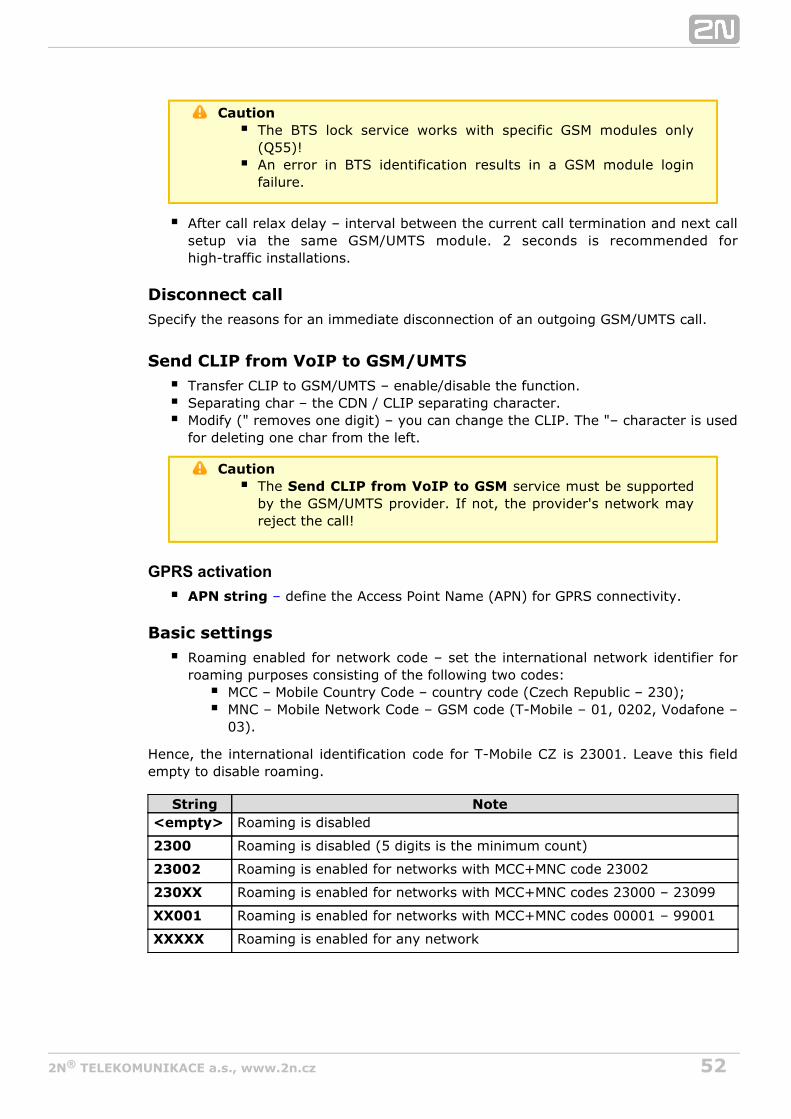
Basic settingsRoaming enabled for network code – set the international network identifier forroaming purposes consisting of the following two codes:
MCC – Mobile Country Code – country code (Czech Republic – 230);MNC – Mobile Network Code – GSM code (T-Mobile – 01, 0202, Vodafone –03).
Hence, the international identification code for T-Mobile CZ is 23001. Leave this fieldempty to disable roaming.
String Note<empty> Roaming is disabled
2300 Roaming is disabled (5 digits is the minimum count)
23002 Roaming is enabled for networks with MCC+MNC code 23002
230XX Roaming is enabled for networks with MCC+MNC codes 23000 – 23099
XX001 Roaming is enabled for networks with MCC+MNC codes 00001 – 99001
XXXXX Roaming is enabled for any network
532N TELEKOMUNIKACE a.s., www.2n.cz®
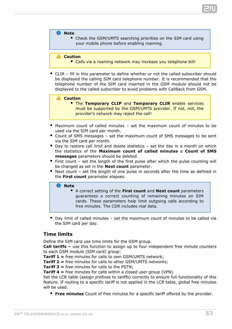
NoteCheck the GSM/UMTS searching priorities on the SIM card usingyour mobile phone before enabling roaming.
CautionCalls via a roaming network may increase you telephone bill!
CLIR – fill in this parameter to define whether or not the called subscriber shouldbe displayed the calling SIM card telephone number. It is recommended that thetelephone number of the SIM card inserted in the GSM module should not bedisplayed to the called subscriber to avoid problems with CallBack from GSM.
CautionThe and enable servicesTemporary CLIP Temporary CLIRmust be supported by the GSM/UMTS provider. If not, not, theprovider's network may reject the call!
Maximum count of called minutes – set the maximum count of minutes to beused via the SIM card per month.Count of SMS messages – set the maximum count of SMS messages to be sentvia the SIM card per month.Day to restore call limit and delete statistics – set the day in a month on whichthe statistics of the a Maximum count of called minutes Count of SMS
parameters should be deletedmessages .First count – set the length of the first pulse after which the pulse counting willbe changed as set in the parameterNext count .Next count – set the length of one pulse in seconds after the time as defined inthe parameter elapsesFirst count .
NoteA correct setting of the and parametersFirst count Next countguarantees a correct counting of remaining minutes on SIMcards. These parameters help limit outgoing calls according tofree minutes. The CDR includes real data.
Day limit of called minutes – set the maximum count of minutes to be called viathe SIM card per day.
Time limitsDefine the SIM card use time limits for the GSM group.
use this function to assign up to four independent free minute countersCall tariffs –to each GSM module (SIM card) group:
free minutes for calls to own GSM/UMTS network;Tariff 1 = free minutes for calls to other GSM/UMTS networks;Tariff 2 = free minutes for calls to the PSTN;Tariff 3 = free minutes for calls within a closed user group (VPN).Tariff 4 =
Set the LCR table (assign prefixes to tariffs) correctly to ensure full functionality of thisfeature. If routing to a specific tariff is not applied in the LCR table, global free minuteswill be used.
Free minutes Count of free minutes for a specific tariff offered by the provider.
542N TELEKOMUNIKACE a.s., www.2n.cz®
Transferred minutes Maximum count of unused free minutes to be transferredto the next period.Day of restoring free minutes Day on which the free minute counters are tobe reset automatically. Choose every 24 hours, a day in a month, or a day in aweek for restoring.Week of restoring free minutes Define the week in which the freein monthminute counters are to be reset automatically. This setting is useful when counterreset takes place on 'every other Friday in month'. Otherwise, leave the 'every'value.
CautionWe recommend you to set the free minute counter value to X–5,where X is the count of free minutes obtained from theGSM/UMTS provider to avoid limit excesses.The manufacturer is not liable for any additional call costs incase the GSM/UMTS provider's free minute/SMS limits areexceeded.

552N TELEKOMUNIKACE a.s., www.2n.cz®
GSM incoming groups
2N VoiceBlue Next® allows you to work with two groups of incoming calls for each ofwhich you can set variable connection set-up modes.
General settingsMode – set how the gateway should process incoming GSM calls:
Reject incoming calls – all incoming GSM calls are automatically rejected.Ignore incoming calls – all incoming GSM calls are ignored. The callingsubscriber gets the check ringing tone.Accept incoming calls + voice message – incoming GSM calls are receivedand, if preset so, the DTMF dial-in with a voice welcome note is activated.Accept incoming calls + dialtone – incoming GSM calls are received and, ifpreset so, the DTMF dial-in function with a simulated secondary dialtone isactivated.CallBack after ring / Reject – in case the CallBack table includes the CLIP, aCallBack is made. CLIP–less incoming calls are rejected.CallBack after ring / Ignore – in case the CallBack table includes the CLIP, aCallBack is made. CLIP–less incoming calls are ignored.Report to PC + voice message – the GSM gateway sends information onincoming calls to a PC equipped with the call routing software. The DTMFdial-in with a voice welcome note can be activated for incoming calls.Report to PC + dialtone – the GSM gateway sends information on incomingcalls to a PC equipped with the call routing software. The DTMF dial-in witha simulated secondary dialtone can be activated for incoming calls.
Minimum digits in DTMF – set the minimum count of digits to be required by thegateway for DTMF dial-in.Maximum digits in DTMF – set the minimum count of digits to be accepted by thegateway for DTMF dial-in.DTMF dialling timeout [s] – set the time for the GSM gateway to wait for the first/ next DTMF digits. If you set this parameter to 0, the incoming call isautomatically connected to the numbers included in the .List of called numbersDay of deleting GSM incl. group statistics – define a day in a month on which thestatistics on incoming calls should be deleted.Prefix before DISA dial-in – enter a numerical prefix to be automatically insertedbefore the DTMF dial-in.CLIP – use this parameter to modify the CLIP from GSM/UMTS networks. '+' isremoved automatically from international identifiers. Use '–' to remove a digit.Examples (GSM CLIP +420600123456):
ParameterCLIP toVoIP/PRI 1
Note
Null 420261301500 No CLIP change
+ +420261301500 + inserted before CLIP received
00 00420261301500 00 inserted before CLIP received
– 0261301500 First two digits removed from CLIP received
–––99 99261301500First three digits removed from CLIP received, prefix'99' added
Looping of voice message – set the voice message playing time.
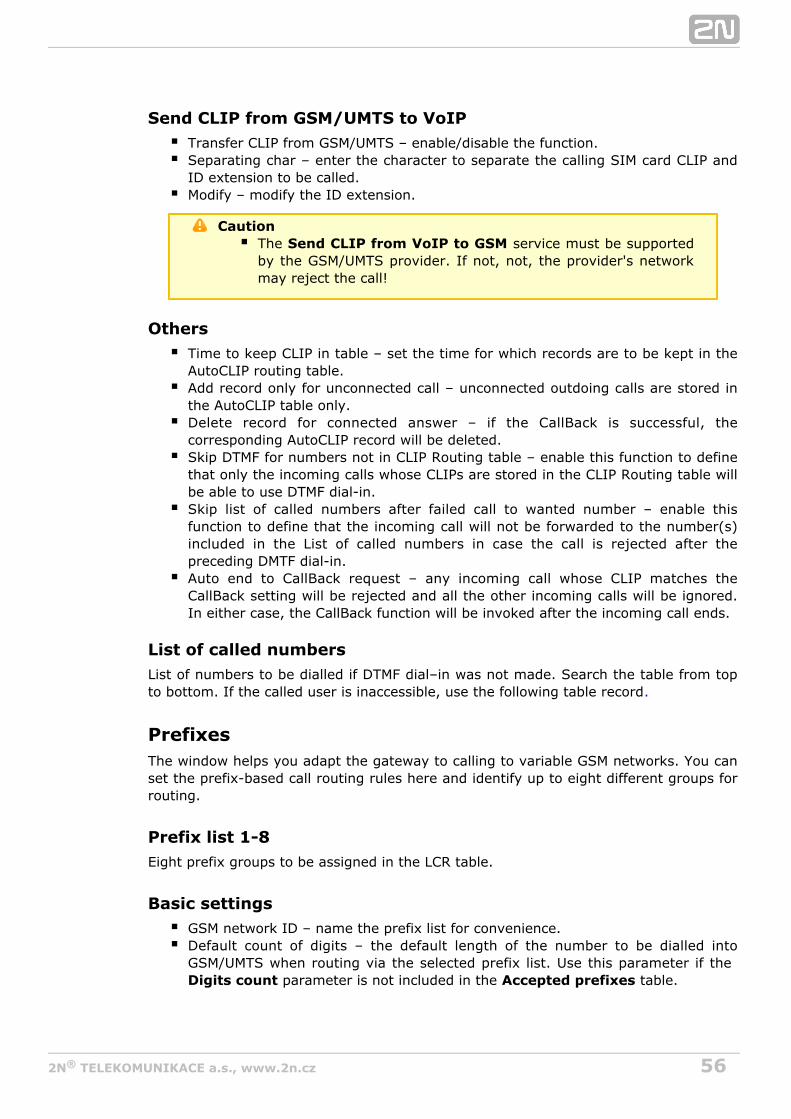
562N TELEKOMUNIKACE a.s., www.2n.cz®
Send CLIP from GSM/UMTS to VoIPTransfer CLIP from GSM/UMTS – enable/disable the function.Separating char – enter the character to separate the calling SIM card CLIP andID extension to be called.Modify – modify the ID extension.
CautionThe service must be supportedSend CLIP from VoIP to GSMby the GSM/UMTS provider. If not, not, the provider's networkmay reject the call!
OthersTime to keep CLIP in table – set the time for which records are to be kept in theAutoCLIP routing table.Add record only for unconnected call – unconnected outdoing calls are stored inthe AutoCLIP table only.Delete record for connected answer – if the CallBack is successful, thecorresponding AutoCLIP record will be deleted.Skip DTMF for numbers not in CLIP Routing table – enable this function to definethat only the incoming calls whose CLIPs are stored in the CLIP Routing table willbe able to use DTMF dial-in.Skip list of called numbers after failed call to wanted number – enable thisfunction to define that the incoming call will not be forwarded to the number(s)included in the List of called numbers in case the call is rejected after thepreceding DMTF dial-in.Auto end to CallBack request – any incoming call whose CLIP matches theCallBack setting will be rejected and all the other incoming calls will be ignored.In either case, the CallBack function will be invoked after the incoming call ends.
List of called numbersList of numbers to be dialled if DTMF dial–in was not made. Search the table from topto bottom. If the called user is inaccessible, use the following table record.
PrefixesThe window helps you adapt the gateway to calling to variable GSM networks. You canset the prefix-based call routing rules here and identify up to eight different groups forrouting.
Prefix list 1-8Eight prefix groups to be assigned in the LCR table.
Basic settingsGSM network ID – name the prefix list for convenience.Default count of digits – the default length of the number to be dialled intoGSM/UMTS when routing via the selected prefix list. Use this parameter if the
parameter is not included in the table.Digits count Accepted prefixes
572N TELEKOMUNIKACE a.s., www.2n.cz®
Table of replaced prefixesThis table helps you change the prefix of the number received (from 00 to +, e.g.). Youcan just add or remove a prefix using this table. This change is performed before theprefix table search is initiated. Keep the „"/ „" record at least in the table for a properfunction.
Table of accepted prefixesA list of prefixes of called destinations to which the selected prefix list applies.
NoteThe maximum count of Accepted Prefixes table records is 128.
LCR tableThe LCR (Least Cost Routing) table helps route calls according to the called numberand depending on the day time and weekday.
Prefix list – select a list of prefixes to be used for the selected LCR row.Time limitation – set a time limitation for a particular LCR row.Weekend usage – enable/disable a particular PCR row during weekends.Maximum call length – set the maximum length (in minutes) for an activeoutgoing call to GSM/UMTS.Groups – set the GSM outgoing groups to be used for the selected LCR row.Tariffs – select the tariff group (free minute counter) to be used for the outgoingcall. Refer to the for more details.GSM outgoing groupsIgnore tone detection in last group – having detected a user defined tone (referto ), the GSM gateway terminates the call and seeks forGSM basic settingsanother call setup option by default. If this parameter is activated, the GSMgateway ignores the tone detection results and sets up the call if this is the lastcall setup option.
NoteYou are recommended to read the Routing Algorithm for
section on p. before setting the LCR table andOutgoing Callsprefix lists.Remember to set the tariffs correctly in the GSM outgoing
section to make tariff routing work properly.groupsThe maximum count of LCR table records is 64.
CLIP routing table + CallBackThe table permanently assigns CLIPs to the extensions to which incoming calls are tobe routed automatically and set the CLIP list for the GMS network for which theCallBack function is enabled.
GSM number (CLIP) – user identification in a GSM/UMTS network.AutoDial – enable/disable CLIP routing for the selected CLIP.Dial to VoIP – enter the VoIP destination number for CLIP routing.Auto CallBack – enable/disable CallBack for the selected CLIP.Limit – set the maximum call length (in minutes).

582N TELEKOMUNIKACE a.s., www.2n.cz®
NoteRemember to activate the CallBack mode in the GSM incoming
window for a proper CallBack function.groupsThe maximum count of CLIP routing table records is 96.
Mobility ExtensionThe table registers the Mobility Extension users.
Name – enter the user name for calling to VoIP.User – enter the registration user name for VoIP.Password – enter the registration user password for VoIP.GSM number (CLIP) – enter the user SIM card CLIP.Follow me function – enable/disable call forwarding to a mobile user station(based on CLIP).SMS at no answer function – enable/disable sending of information SMS onmissed calls.
NoteYou are recommended to read the Mobility Extension section onpage carefully before using the Mobility Extension function.
Ethernet configurationThis window helps you configure the Ethernet interface of your gateway.
Use DHCP – enable/disable the DHCP client function in .2N VoiceBlue Next®
IP address – the fixed IP address (v4) of the Ethernet2N VoiceBlue Next®
interface.Subnet mask – the subnet mask for the Ethernet2N VoiceBlue Next®
interface.Default gateway – The IP gateway IP address (v4) in the Ethernet network.
– primary DNS server.DNS server1 – secondary DNS server. Used as a back-up when DNS server 1 isDNS server2
not functional.
CautionIncorrect settings, e.g. enabling the service, mayDHCP clientresult in a denial of access to the 2N VoiceBlue Next®
configuration. To avoid this, restore the GSM gateway defaultsettings. Refer to for details.Subs. 3.1
TipIn case the gateway is in the DHCP client mode, currentassignments obtained from the DHCP server are displayed inthe , and items.IP address Subnet mask Default gateway
592N TELEKOMUNIKACE a.s., www.2n.cz®
Login configuration
The window helps you set the access password and name for the 2N VoiceBlue®
web interface. Use the same data for Telnet connection too.Next
CautionRemember to the username and password thechange duringfirst gateway configuration to avoid unauthorised access!
Web configurationSet additional parameters for the gateway web interface.
Auto logout – set the count of minutes in which the current user should belogged out automatically.Enable web session lock – by default, one Admin user may only be connected tothe GSM gateway at a moment. If another authorised user tries to log in, theprevious session will be aborted automatically. By activating this function youdisable such automatic logout and block any further access attempts.Simple login form – here you can change the login window graphic lay-out. Uponactivation, the GSM gateway login page will have an anonymous appearance.This function is recommended for connecting the gateway to the Internetdirectly.Use SMS user for SMS operations on the web – enable/disable the userauthorised for SMS sending/receiving only.SMS user name/password – the gateway enables independent connection of auser authorised for SMS receiving/sending only.
Report configurationThis window is used for setting details on automatic tracing generated by the GSMgateway.

602N TELEKOMUNIKACE a.s., www.2n.cz®
MessagingThis group helps:
Set the GSM gateway to send/receive SMS via SMTP/POP3 or SMPPDefine the routing rules for incoming and outgoing SMS messagesCheck the GSM gateway SMS database filling capacity
CautionThis service is file-licensed. Refer to Management–>Licence
for the current GSM gateway licence details.key
Modules Grouping
Global settings SMS server enabled – enable/disable the SMS server at the GSM gateway
(keep disabled if you select another SMS processing method).
set the maximumAutoCLIP routing expires [hours] (1-10000, 0=off) – time for keeping of the automatic SMS routing record (response) in the AutoCLIPtable.
Modules to SMS groups assignmentThis section helps you assign GSM modules to SMS groups (according to the GSMprovider, e.g.) to facilitate incoming/outoging SMS routing.
SMS groups to User groups assignment This section helps you assign SMS groups to User groups for SMS sending/recevingpurposes. The GSM gateway can contain up to four User groups.
CautionThe count of user accounts is file-licensed. Refer to
for the current GSM gatewayManagement–>Licence keylicence details.
612N TELEKOMUNIKACE a.s., www.2n.cz®
UsersThis section helps you manage the SMS users. Select a communication protocol foruser adding (SMTP/POP3 or SMPP).
Add userassign the user to a User group.User group –
define the system user name.User full name – define the number (CPN) to which the user'sReplace dial for outgoing SMS –
outgoing SMS messages shall be sent.select the communication protocol for SMS processing:Access type –
define the login name for the client Email.Login name (without domain) – Email (SMTP/POP3) – use SMTP for SMS sending and POP3 for SMSreceiving.
– set the GSM gateway into the 'SMS centre' mode.SMPP (SMSC) – set the GSM gateway into the 'ESME - External ShortSMPP (ESME)
Messaging Entity' mode.SMSC user ID.System ID –
SMSC/SMTP user password.Password – ESME user ID.System ID (for authentication on remote side) –
ESME user ID.Password (for authentication on remote side) – set the TCP parameter into the client/server mode.TCP type –
set the server IP address and TCP server transport port.Server address – set the ESME user details:Message direction of Esme –
Transceiver – ESME works as a transmistter/receiver.ESME works as a transmitter.Transmitter –
ESME works as a receiver.Receiver – Address range – set this parameter if required so by SMSC for SMS receiving.
Delivery status required – set the SMS sending request for outgoing SMSdelivery confirmation.
Send message as Flash SMS – activate the Flash SMS function for outgoingSMS messages.
NoteYou can set the parameter only if theDelivery status required SMTP/POP3 protocol is used. With SMPP, the delivery information is active automatically incase the service is required by the SMPP counterparty or via anincoming SMS message from the GSM/UMTS network.

622N TELEKOMUNIKACE a.s., www.2n.cz®
User GroupThis section helps you edit the User group and set the routing rules for the group'sincoming and outgoing SMS.
General settingsSet the basic parameters for SMS sending via SMTP/POP3 or SMPP.
Optional informationsDescription – set the User group details.Identical SMS limit – set the check of identical SMS messages, i.e. sequentiallysent messages with identical SMS PDUs. When the set limit is exceeded, theexcessive SMS messages are discarded without being sent.

632N TELEKOMUNIKACE a.s., www.2n.cz®
Email settingsDomain – define the domain name for SMS sending/receiving via SMTP/POP3.POP3 - Subject of email – set the message subject to be added automaticallyto the SMS loaded from the GSM gateway via POP3.POP3 - Subject of email (delivery acknowledgement) – set the SMSdelivery acknowledging message subject.
– set the SMS non-deliveryPOP3 - Subject of email (not delivered)acknowledging message subject.
– set the SMS sending failure messagePOP3 - Subject of email (send error)subject.SMTP - Maximum SMS per email – set the maximum count of SMS messagesto be sent within one Email message. Any characters exceeding the set lengthwill be ignored.SMTP - Add "From" to SMS – add 'From' from the Email message to theoutgoing SMS. The sender information will be displayed at the beginning of theSMS message. SMTP - Add "Subject" to SMS – add 'Subject' from the Email message to theoutgoing SMS. The subject information will be displayed at the beginning of theSMS message.
642N TELEKOMUNIKACE a.s., www.2n.cz®
SMPP address modification Source address of message incoming from SMPP – set how to modify themessage sender ID received via SMPP.
Never replace original addressReplace if the original address is emptyAlways replace original address
address – enter sender's new ID TON – type of number – numbering plan indicatorNPI
Destination address of message incoming from SMPP – set how to modifythe message addressee telephone number received via SMPP.
Never replace original addressReplace if the original address is emptyAlways replace original address
address – enter addressee's new telephone number TON – type of number – numbering plan indicatorNPI
Source address of message outgoing to SMPP – set how to modify themessage sender ID to be sent via SMPP.
Never replace original addressReplace if the original address is emptyAlways replace original address
address – enter sender's new ID TON – type of number – numbering plan indicatorNPI
Destination address of message outgoing to SMPP – set how to modify themessage addressee telephone number to be sent via SMPP.
Never replace original addressReplace if the original address is emptyAlways replace original address
address – enter addressee's new telephone number TON – type of number – numbering plan indicatorNPI
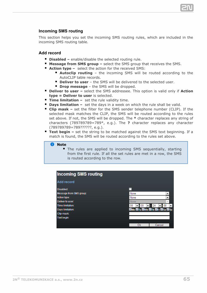
652N TELEKOMUNIKACE a.s., www.2n.cz®
Incoming SMS routingThis section helps you set the incoming SMS routing rules, which are included in theincoming SMS routing table.
Add recordenable/disable the selected routing rule.Disabled –
select the SMS group that receives the SMS.Message from SMS group – select the action for the received SMS:Action type –
– the incoming SMS will be routed according to theAutoclip routingAutoCLIP table records.
– the SMS will be delivered to the selected user.Deliver to user – the SMS will be dropped.Drop message
select the SMS addressee. This option is valid only if Deliver to user – Action is selected.type = Deliver to user
set the rule validity time.Time limitation – set the days in a week on which the rule shall be valid.Days limitation –
set the filter for the SMS sender telephone number (CLIP). If theClip mask – selected mask matches the CLIP, the SMS will be routed according to the rulesset above. If not, the SMS will be dropped. The character replaces any string of*characters (789789789=789*, e.g.). The character replaces any character?(789789789=789??????, e.g.).
set the string to be matched against the SMS text beginning. If aText begin – match is found, the SMS will be routed according to the rules set above.
NoteThe rules are applied to incoming SMS sequentially, startingfrom the first rule. If all the set rules are met in a row, the SMSis routed according to the row.

662N TELEKOMUNIKACE a.s., www.2n.cz®
Outgoing SMS routingThis section helps you define the outgoing SMS routing rules, which are included in theoutgoing SMS routing table.
Add recordenable/disable the selected routing rule. Disabled –
select the SMS group via which the SMS will be sent.Message to SMS group – select the action for the outgoing SMS:Action type –
Submit from user – enable sending SMS from the selected user. – enable sending SMS from all the SMS groupSubmit from all users
users.select the user in case Submit from user – Action type = Submit from user
is selected. set the rule validity time. Time limitation – set the days in a week on which the rule shall be valid.Days limitation –
set the filter for the SMS addressee telephone number (Dial). If theDial mask – selected mask matches the Dial, the SMS will be routed accroding to the rules setabove. If not, the SMS will be rejected and deleted. The * character replaces anystring of characters (789789789 = 789*, e.g.). The ? character replaces anycharacter (789789789 = 789??????, e.g.).
set the string to be matched against the SMS text beginning. If aText begin – match is found, the SMS will be routed according to the rules set above.
NoteThe rules are applied to outgoing SMS sequentially, startingfrom the first rule. If all the set rules are met in a row, the SMSis routed according to the row.
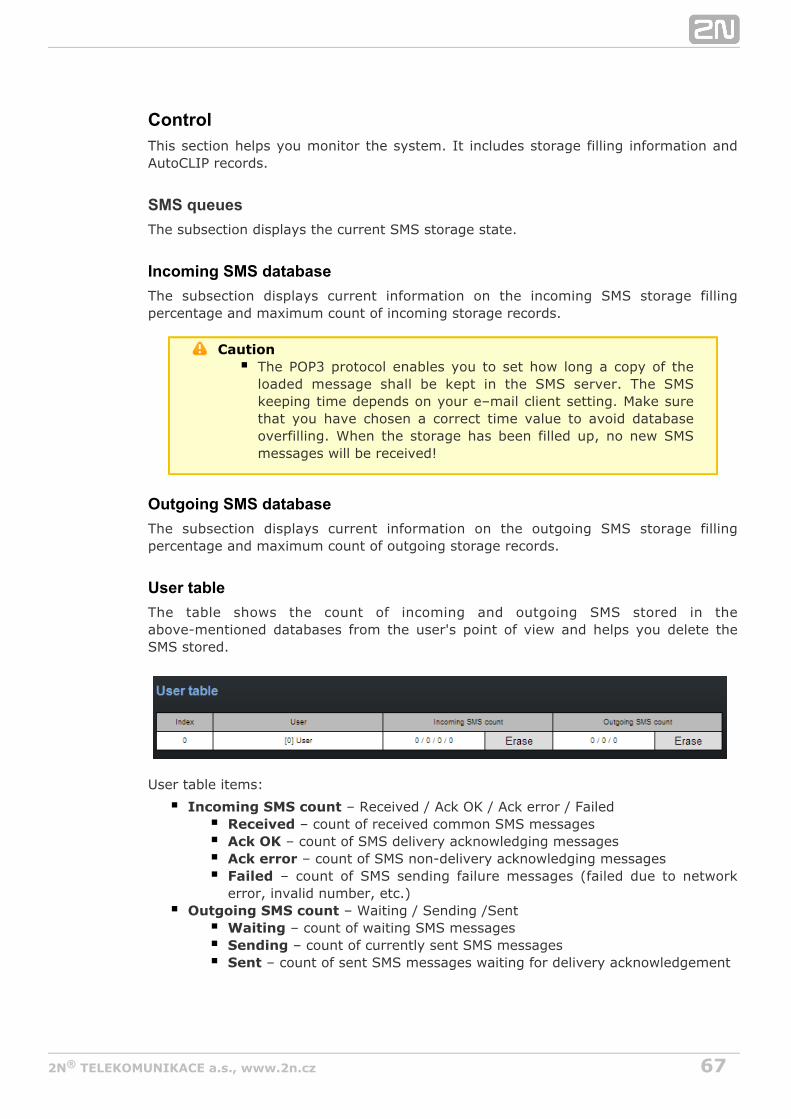
672N TELEKOMUNIKACE a.s., www.2n.cz®
ControlThis section helps you monitor the system. It includes storage filling information andAutoCLIP records.
SMS queuesThe subsection displays the current SMS storage state.
Incoming SMS databaseThe subsection displays current information on the incoming SMS storage fillingpercentage and maximum count of incoming storage records.
CautionThe POP3 protocol enables you to set how long a copy of theloaded message shall be kept in the SMS server. The SMSkeeping time depends on your e–mail client setting. Make surethat you have chosen a correct time value to avoid databaseoverfilling. When the storage has been filled up, no new SMSmessages will be received!
Outgoing SMS databaseThe subsection displays current information on the outgoing SMS storage fillingpercentage and maximum count of outgoing storage records.
User tableThe table shows the count of incoming and outgoing SMS stored in theabove-mentioned databases from the user's point of view and helps you delete theSMS stored.
User table items:
– Received / Ack OK / Ack error / FailedIncoming SMS count – count of received common SMS messagesReceived
– count of SMS delivery acknowledging messagesAck OK – count of SMS non-delivery acknowledging messagesAck error
– count of SMS sending failure messages (failed due to networkFailederror, invalid number, etc.)
– Waiting / Sending /SentOutgoing SMS count – count of waiting SMS messagesWaiting – count of currently sent SMS messagesSending
– count of sent SMS messages waiting for delivery acknowledgementSent

682N TELEKOMUNIKACE a.s., www.2n.cz®
AutoCLIP routing tableThe window displays the current state of the AutoCLIP table.

692N TELEKOMUNIKACE a.s., www.2n.cz®
1. a.
b.
2. a. b. c.
d. 3.
a.
b.
c.
SMPP Basic Configuration – Step by StepThis section helps you define the basic parameters for SMS sending/receiving via SMPPin . Read the subsection carefully before setting2N VoiceBlue NEXT® Messagingdetails.
shows sending/receiving SMS via SMPP. Having created user accounts in Figure 1 2N, the users can send/receive SMS via SMPP. The figure shows an VoiceBlue NEXT®
example with two SMSC accounts created in (to the right).2N VoiceBlue NEXT®
Another (ESME) gateway and a PC on which the SMPP (ESME)2N VoiceBlue NEXT®
application is running are connected to these accounts via SMPP. An SMS coming to 2N via SMPP is routed according to the gateway outgoing routing rules VoiceBlue NEXT®
and sent to GSM. An SMS coming from GSM is routed according to the gatewayincoming routing rules and sent to the destination via SMPP.
SMPP CommunicationFigure 1:
Take the following basic steps in to enable SMS2N VoiceBlue NEXT®
sending/receiving:
In the menu: Monitoring–>SMS grouping Assign the selected GSM modules to the SMS groups (according to the GSMprovider and SIM cards with identical tariffs, for example).Assign the SMS groups created in step 1.a above to the User groups if youuse messaging with different routing rules to different companydepartments, for example.
Add users in the menu:Monitoring–>Users–>Add Assign the user to a .User groupSet Access type: SMPP (SMSC).Set and to access the GSM gateway SMS server viaSystem ID PasswordESME.Set .TCP type: server
Create the incoming SMS routing rules in the Messaging–>UserGroup–>General settings–>Incoming SMS routing–>Add menu:
Select the group to receive the SMS via the Message from SMS group menu.Select the to define how to process incoming SMS. Example:Action type Set to deliver SMS to selected users.Action type: Deliver to user

702N TELEKOMUNIKACE a.s., www.2n.cz®
3.
c. 4.
a.
b.
c. 5.
Set to to define the SMS receiving user.Deliver to user Create the outgoing SMS routing rules in the Messaging–>User
menu:Group–>General settings–>Outgoing SMS routing–>Add Enable the SMS server in the –>Messaging Modules grouping–>SMS serverenabled menu.
Set the via which the outgoing SMS will be routed in the SMS groupmenu.Message to SMS group
Select the to define how to process outgoing SMS. Example:Action type Set to send SMS from selected users.Action type: Submit from userSet to define the SMS sending user.Submit from user
Should you get in troubles, follow the steps below please:
Read the User Manual carefully and check all parameters.Find answers to the frequently asked questions at .http://faq.2n.czConsult your servicing partner.
You are recommended to attend a 2N certified training to improve your installationchances.

712N TELEKOMUNIKACE a.s., www.2n.cz®
1. a.
b.
2. a. b. c.
3.
a.
SMTP/POP3 Basic Configuration – Step by StepThis section helps you define the basic parameters for SMS2N VoiceBlue NEXT®
sending/receiving via SMTP/POP3. Read the subsection carefully beforeMessagingsetting details.
shows sending/receving SMS via SMTP/POP3. Having created user accountsFigure 1in , the users can access the accounts via the e-mail client and2N VoiceBlue NEXT®
send SMS messages to via SMTP. The gateway receives the2N VoiceBlue NEXT®
messages and resends them to the GSM users according to the predefined routingrules.A message coming to from GSM is routed according to the2N VoiceBlue NEXT®
incoming SMS rules and delivered to the user via POP3.
SMTP/POP3 CommunicationFigure 1:
NoteYou can send an SMS message of any length to up to 100 usersat the same time from the e-mail client. The maximum SMScount per e-mail is only limited by the –>User group General
–> settings.settings SMTP Maximum SMS per email
Take the following basic steps in to enable SMS2N VoiceBlue NEXT®
sending/receiving:
In the menu: Monitoring–>SMS grouping Assign the selected GSM modules to the SMS groups (according to the GSMprovider and SIM cards with identical tariffs, for example).Assign the SMS groups created in step 1.a above to the User groups if youuse messaging with different routing rules to different companydepartments, for example.
Add users in the menu:Monitoring–>Users–>Add Assign the user to a .User groupSet .Access type: Email(SMTP/POP3)Define the and to log in to theLogin name (without domain) PasswordSMS server via your e-mail client.
Set the Domain in the Messaging–>User Group–>General settings–>Emailmenu.settings–>Domain
Set the user domain. The domain is automatically assigned to the username in the selected User group and represents the user e-mail address.Example: Suppose a user was created in step 2.c with Login name: USER and domain , then the e-mail address of the userDomain: email.com
722N TELEKOMUNIKACE a.s., www.2n.cz®
3.
a.
4.
a. b.
c. 5.
a.
b.
c. 6.
with the right to access the SMS server will be . The @[email protected] is completed automatically and is not included in the Domain:field.
Create the incoming SMS routing rules in the Messaging–>Usermenu:Group–>General settings–>Incoming SMS routing–>Add
Select the group to receive the SMS via the . Message from SMS groupSelect the to define how to process incoming SMS. Example:Action type Set to deliver SMS to selected users.Action type: Deliver to userSet to define the SMS receiving user.Deliver to user
Create the outgoing SMS routing rules in the Messaging–>Usermenu:Group–>General settings–>Outgoing SMS routing–>Add
Enable the SMS server in the –>Messaging Modules grouping–>SMS server menu.enabled
Set the via which the outgoing SMS will be routed in the SMS groupMessage to SMS group menu.Select the to define how to process outgoing SMS. Example:Action type Set to send SMS from selected users.Action type: Submit from userSet to define the SMS sending user.Submit from user
Should you get in troubles, follow the steps below please:
Read the User Manual carefully and check all parameters.Find answers to the frequently asked questions at .http://faq.2n.czConsult your servicing partner.
You are recommended to attend a 2N certified training to improve your installationchances.

732N TELEKOMUNIKACE a.s., www.2n.cz®
MonitoringThis section helps you configure sending of SNMP traps. Download the list of availabletraps, i.e. the MIB table, from the gateway web interface. The main purpose of SNMPmonitoring is to observe your GSM gateway states continuously and send stateinformation to the defined IP addresses whenever an error occurs.
Refer to the for the list of all SNMP traps sent by List of SNMP traps 2N VoiceBlue®
. NEXT
CautionThis service is subject to licence! Refer to
for the current GSM gatewayManagement–>Licence key licence state details.
Common Settings
General define the maximum/minimum level of the signal received by theSignal level –
GSM/UMTS module. The SNMP trap is sent automatically whenever the definedvalues are exceeded.
– define the maximum filling capacity of the SMSSMS bufer upper limitstorage. The SNMP trap is sent automatically whenever the defined value isexceeded.
SNMP
General – enable/disable the SNMP service.Enabled
– SNMP community is a group that owns the device and controlCommunitystations on which SNMP is running. Default value = public.

742N TELEKOMUNIKACE a.s., www.2n.cz®
Servers – the addressee's primary IP address and transport port forFirst SNMP server
SNMP traps (default port = 162). Please make sure that the parameters havebeen completed correctly to avoid SNMP malfunction.
– the addressee's secondary IP address and transportSecond SNMP serverport for SNMP traps (default port = 162). If these parameters are correctlycompleted, the SNMP traps will be sent both to the primary and secondary IPaddresses.
Download MIB filesThis section helps you download the MIB files that are necessary for a proper functionof your MIB browser.
CautionThe SNMP service works properly on condition that
SNMP is licensed in the section.ManagementThe primary IP address, transport port and communityparameters are completed.SNMP is enabled in the section.eMonitoring
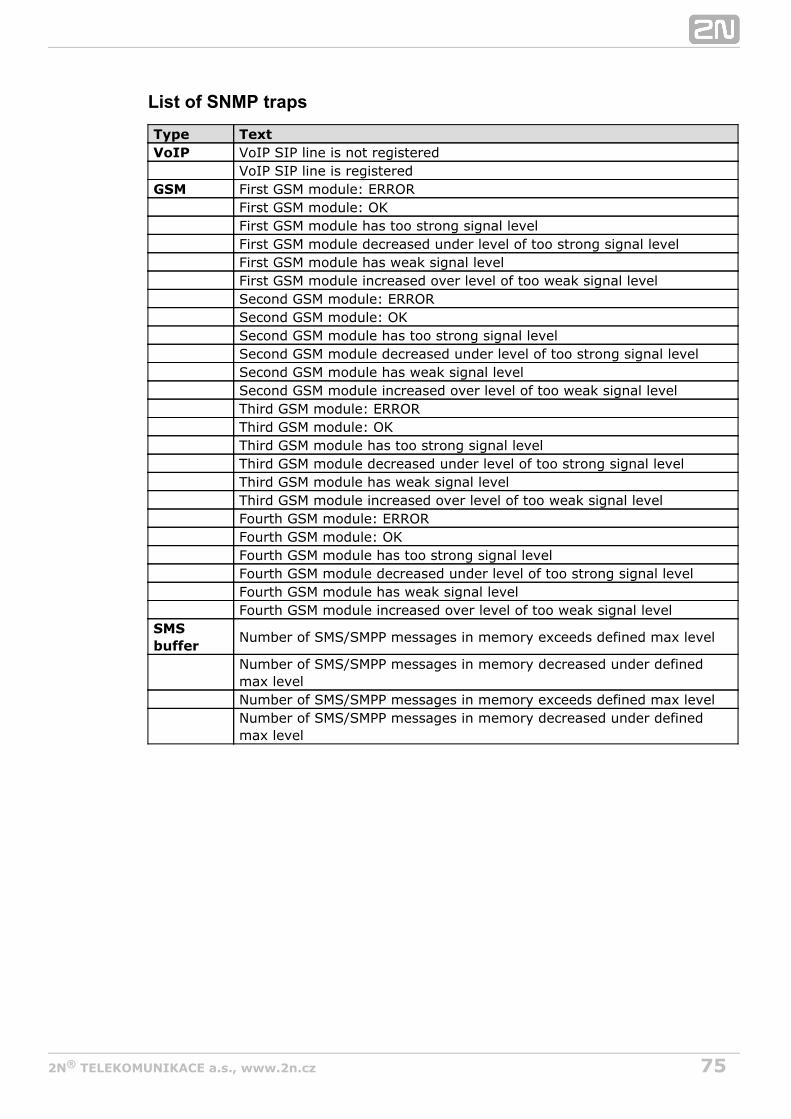
752N TELEKOMUNIKACE a.s., www.2n.cz®
List of SNMP traps
Type TextVoIP VoIP SIP line is not registered VoIP SIP line is registeredGSM First GSM module: ERROR First GSM module: OK First GSM module has too strong signal level First GSM module decreased under level of too strong signal level First GSM module has weak signal level First GSM module increased over level of too weak signal level Second GSM module: ERROR Second GSM module: OK Second GSM module has too strong signal level Second GSM module decreased under level of too strong signal level Second GSM module has weak signal level Second GSM module increased over level of too weak signal level Third GSM module: ERROR Third GSM module: OK Third GSM module has too strong signal level Third GSM module decreased under level of too strong signal level Third GSM module has weak signal level Third GSM module increased over level of too weak signal level Fourth GSM module: ERROR Fourth GSM module: OK Fourth GSM module has too strong signal level Fourth GSM module decreased under level of too strong signal level Fourth GSM module has weak signal level Fourth GSM module increased over level of too weak signal levelSMSbuffer
Number of SMS/SMPP messages in memory exceeds defined max level
Number of SMS/SMPP messages in memory decreased under definedmax level
Number of SMS/SMPP messages in memory exceeds defined max level
Number of SMS/SMPP messages in memory decreased under definedmax level

762N TELEKOMUNIKACE a.s., www.2n.cz®
Others
SIM ClientThis section is displayed for those GSM gateways only that support the 2N SIM Star®
system connection – remote SIM card function.
SMSThis subsection helps you send and receive SMS via the modules.
TipYou can also use the SMS user account for SMSsending/receiving. Refer to the Web Configuration subsection forSMS user configuration details.
UtilsThis section provides extra functions of the GSM gateway. Currently, they includeEthernet interface tracing ( ), which helps detect gateway installationNetwork traceproblems, such as SIP communication debugging. The downloaded file is in the PCAPformat, which is, for example, readable by WireShark ( ).http://www.wireshark.org/
Management
Firmware updateIn this menu you can store new firmware into the GSM gateway. Select the
files only. Refer to the Firmware Upgrade subsection on page VBN–xx.xx.xx.bin Brief for more firmware information.Installation Guide
WarningUse the for this gateway type only! Anyfirmware certifiedother firmware type may damage 2N VoiceBlue®
!Next irreversibly
After the new firmware file is stored and sent, the GSM gateway is restartedautomatically.

772N TELEKOMUNIKACE a.s., www.2n.cz®
Licence key This section helps you upload the licence file/code to 2N VoiceBlue NEXT ® and
provides information on the current licence file. Refer to for moreGateway Controldetails.
CautionBy inserting a new licence code you restart the GSM gatewayand discontinue all the currently made calls!
RestartThis subsection provides information on a forced restart of .2N VoiceBlue Next®
Configuration download
The window helps you download the current configuration. The2N VoiceBlue Next®
file format is .CFG–M202–gateway_serial_number–rrrrmmdd–hhmmss.tar
Configuration upload
The window helps you upload new configuration settings into co2N VoiceBlue Next®
nfiguration. The Ethernet interface and login data remain the same!
WarningBe sure to upload the configuration file intended for the selectedGSM gateway only to avoid malfunction of the GSM gateway andthe necessity to restart the system.
Configuration ResetThis subsection helps you restore the default configuration (except for Ethernet andlogin).
– enable/disable keeping of the LCR table records .Including LCR table – enable/disable keeping of the CLIP routingIncluding CLIP routing table

782N TELEKOMUNIKACE a.s., www.2n.cz®
table records.
DocumentationDownload the User Manual saved in the gateway.
CautionThe User Manual version will not change during the gatewayfirmware upgrade. Click on the link to for the latestwww.2n.czUser Manual version!

792N TELEKOMUNIKACE a.s., www.2n.cz®
4. Terminal
This section describes communication with using a terminal.2N VoiceBlue Next®
Here is what you can find in this section:
4.1 Terminal-Based Communication4.2 AT Interface4.3 LOGs4.4 CDR4.5 SDR4.6 Available Status Messages4.7 Statistics4.8 Tracing4.9 External SMS Control

802N TELEKOMUNIKACE a.s., www.2n.cz®
4.1 Terminal-Based Communication2N VoiceBlue Next® allows for communication via the TCP/IP Telnet protocol. Themaximum count of active Telnet sessions is . If there are more Telnet connectiontenrequests than ten, the GSM gateway rejects the connection.
Terminal2N VoiceBlue Next® acts as an ANSI terminal with echo. Text commands are enteredin one of the following formats: AT[command]<CR>, or AT[command]<CR><LF>. Theanswer consists of up to several rows, an empty row with <CR><LF> and the replytype: OK, ERROR, or BUSY. Use A/<CR> to repeat the command.
The gateway requests a password by displaying the and prompts.Login: Password:It uses an extended set of AT commands for configuration. Refer to for theSubs.4.2list of terminal AT commands.
Example of a login window:
[ VoiceBlue Next ] V–01.00.01 B–00.91
Date/time: 15.1.2010/20:56:53.98
SNumber: M202–1501270008
Login: Admin
Password: **
Access Data2N VoiceBlue Next® receives Telnet requests on port 23. Port 23 can not bereconfigured.
The access password and name are identical with those of the web interface. Theaccess data cannot be changed from the gateway Telnet interface (only from the webinterface) for security reasons.
Refer to for access data factory settings.Subs. 2.2
812N TELEKOMUNIKACE a.s., www.2n.cz®
4.2 AT Interface2N VoiceBlue Next® uses the list of AT commands derived from the standard AT setfor configuration and monitoring purposes.
The configuration entering commands start with AT%parameter_id.
The configuration writing out commands start with AT§ion.
The following list of AT commands is universal and some commands may not beincluded in .2N VoiceBlue Next®

822N TELEKOMUNIKACE a.s., www.2n.cz®
Basic Commands
System Information
ATI3 Firmware version and copyright
ATI4 Factory number
Statistics
AT&T Statistics of calls via PRI interface
AT&TIN Statistics of incoming calls via GSM modules
AT&TOUT Statistics of outgoing calls via GSM modules
AT&T##Statistics of calls via SIM cards of GSM module##
AT%TPR=mi,ci,mo,co Setting of statistics via PRI
AT%TG0=mi,ci,0,0Setting of statistics of incoming calls via all GSMmodules in GSM group 0
AT%TG#=mi,co,ri,ro Settings of statistics of GSM group #
AT%TGALL=mo.co,ri,ro Settings of statistics of all GSM groups
AT%T##=#,mi,ci,si,mo,co,soSettings of statistics of SIM card # of GSMmodule ##
AT%T##=ALL,mi,ci,si,mo,co,soSettings of statistics of all SIM cards of GSMmodule ##
AT%TALL=ALL,mi,ci,si,mo,co,soSettings of statistics of all SIM cards of all GSMmodules
Description of parameters:
Mi/mo > Minutes of incom./outg. callsCi/co >number of connected incom./outg. callsRi/ro >number of re–routed incom/outg. calls ingroupSi/so > number of received/sent SMSmessages
! When you change theseparameters, all the othercounters will be reset!!
Wireless Engines
AT&Q## Received GSM signal level (##=00–15)
AT&QALL Received GSM signal level from all GSM modules
AT&Gxx=atcmdSend command for AT commands directly toGSM module
AT&Gxx=at+cnum – SIM card telephonenumberAT&Gxx=at+cpin="xxxx" – PIN enteringAT&Gxx=at+clck="sc",1"xxxx" – PIN requestenableAT&Gxx=at+clck="sc",0"xxxx" – PIN requestdisable

832N TELEKOMUNIKACE a.s., www.2n.cz®
LOG and CDR List
AT&LLog file listing (PRIGW awaits pressing of theSpace bar after every 20 lines)
AT&CCall file listing (PRIGW awaits pressing of anykey after every 20 lines)
AT&CRCall file listing and deleting (PRIGW awaitspressing of the # key to delete this line /withcall info/ from memory and sends next line)

842N TELEKOMUNIKACE a.s., www.2n.cz®
Configuration commands
Status Information
AT&V Overview of all system settings
AT&VI Overview of ISDN PRI settings
AT&V0 Overview of basic GSM settings
AT&V# Overview of GSM group # settings (#=1–8)
AT&VALL Overview of all GSM group settings
AT&N#Overview of parameters of network list #(#=1–8)
AT&NALL Overview of parameters of all network lists
AT&R Overview of LCR lines
Default Reset
AT&FRES Reset with gateway factory settings
System Settings
AT%S70=x.x.x.x IP address
AT%S71=x.x.x.x IP address mask
AT%S81=Initialisation string for setting of mode connectedto the gateway COM2
AT%S90=xType of assignment of B–channels to GSMmodules (0–rotating; 1–locked; 2–according tocredit)
AT%S91=x,y
Way of call information recording (0– no record;1– successfully connected outgoing call; 2–successfully connected incoming calls; 3–successfully connected incoming and outgoingcalls; 5– all outgoing calls; 6– all incoming calls;7–all incoming+outgoing calls)Y = to each call add NET info (1) or no (0)
AT%S93=xGlobal selection of SIM card (0= according toGSM group, 1–8= number of SIM holder)
AT%S98=xxxx PIN code for SIM cards inserted in the gateway
AT%S99=dd.mm.yy.w/hh:mm:ss
Gateway date and time settings
AT%X00=hout,hin,min
Automatic logout of GSM moduleshout ...hourwhen the modules start to log out randomlyhin...hour when the modules start to log inrandomlymin ...minimum number of modules ina group (2..15) that always remain logged–in
AT%X80=name/passUsername/password for access via IP port (thisparameter is write only– you cannot see itsvalue)

852N TELEKOMUNIKACE a.s., www.2n.cz®
System Control AT&BSYS=RESET Reset of PRIGW
AT&Gxx=RESET Reset of GSM module xx
AT&Gxx=BLOCK Block of GSM module xx
AT&Gxx=DOWN Transfer of GSM module into the sleep mode
AT&Gxx=ON Transfer of GSM module into the idle mode
Basic GSM Settings
AT%G00=rr,gggggg,gggggg,gggggg,gggggg,gggggg
g,r=Number of GSM group for each GSM module
AT%G01=mode,atms,atfs
Voice processing settings (for GM22 GSMmodules only)mode – algorithm (0–none, 1–semiduplex,2–fullduplex)atms,atfs – transit, receive gain(3=+5dB, 1=+2.5dB, 0=0dB, 2=–2.5dB,4=–5dB
AT%G02=mode,atms,atfs
Voice processing settings (for TC35 GSMmodules only)mode – algorithm (2–echo canceller)atms,atfs –transit, receive gain (3=+5dBm, 1=+2.5dB,0=0dB, 2=–2.5dB, 4=–5dB
AT%G06=mmdd,…mmdd…List of holiday days (mm–month;dd–day), maxlength of line is 63 chars!
AT%G07=mmdd,…mmdd Net list of holiday days
AT%G08=delay,min,max,tout
Parameters of dialling from ISDN to GSMdelay–relax delay between callsmin – minimum lengthof number dialled from ISDNmax – maximumlength of number dialled from ISDNtout – delaybetween dialled digits
GSM Settings (X–GSMGroup)
AT%G#0=sim
Mode of switching SIM card
sim=0: 0 – OFF – group is turned-off
sim>0: 1-4 – SIM card 1-4; 5 – switching bytime; 6 – switching at random time
AT%G#1=netid,clir,min,sms,sec,sec2,pseudo
Basic parameters of SIM card in slot 1netid–network numberclir – 0=default,1=enabled,2=disabledmin –maximum number of minutes called sms –maximum number of SMS sent sec – minimumcall length (not for cdr info)sec2 – accuracy ofcall length measurement (not for cdr info)pseudo– default = 0
AT%G#2=netid,clir,min,sms,sec,sec2,pseudo
Basic parameters of SIM card in slot 2
List of Networks

862N TELEKOMUNIKACE a.s., www.2n.cz®
AT%N#0=op/np,…op/npList of prefixes replaced by new prefixes(#–number of netlist; op–old prefix;np–newprefix)
AT%N#1=pr/n,…pr/nList of prefixes dialled into ISDN (to be used forLCR table) pr=prefix n=length of number(parameter /n is optional)
AT%N#2..7=pr/n,…pr/n Other 7 lists of prefixes dialled into ISDN
AT%N#9=net,maxNet–network number, max–default length ofnumber dialled from ISDN
LCR Table
AT&R Shows LCR table
AT%R##=net,hh:mm/hh:mm/w,gr*
Settings of line ## (0..63) of LCR tablenet –number of network list (0..8)hh:mm/hh:mm/w*– line using time limitation gr – GSM groupnumbers
Test Calls
AT!SGxx=dial
Initiates testing call from AUX interface (xx isthe called interface):00..31 GSM module32– to GSM via GSM module according to callprefix
AT!WGxx
Connects the following call from interface xx toAUX interface00..31 from GSM No.32 first incoming calls from GSM
AT!D Terminates call on AUX interface
TraceTrace can be activated for only onesession at a time
AT!REStart tracing of error messages on activeinterface
AT!LxStart tracing of LAN & Telnet on layer xx=2 –Layers IP,TCP,Telnetx=3 – Layers TCP,Telnetx=4 – Layer Telnet
AT!RxStart tracing of ISDN PRI & GSM on layer xx=1 –Layers 1,2,3,4x=2 – Layers 2,3,4x=3 – Layers3,4x=4 – Layer 4
AT!RR Start tracing (AT!R2) to COM1 interface
AT!RX Stop tracing (AT!R2) to COM1 interface
SMS ControlSMS control can be activated for onlyone session at a time
AT!G=#A6 – activate control via used session55 –deactivate control via used session99 –deactivate control on all sessions
AT^MS=ch Module status ch=0 – 31
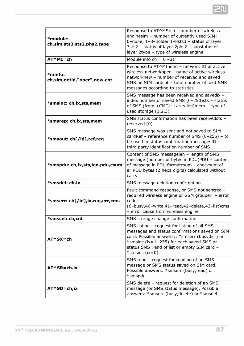
872N TELEKOMUNIKACE a.s., www.2n.cz®
*module:ch,sim,sts3,sts2,phs2,type
Response to AT^MS:ch – number of wirelessenginesim – number of currently used SIM:0–none, 1–8–holder 1–8sts3 – status of layer3sts2 – status of layer 2phs2 – substatus oflayer 2type – type of wireless engine
AT^MI=ch Module info ch = 0 –31
*minfo:ch,sim,netid,"oper",new,cnt
Response to AT^MInetid – network ID of activewireless networkoper – name of active wirelessnetworknew – number of received and savedSMS on SIM cardcnt – total number of sent SMSmessages according to statistics
*smsinc: ch,ix,sts,mem
SMS message has been received and savedix –index number of saved SMS (0–250)sts – statusof SMS (from +CMGL: ix.sts.len)mem – type ofused storage (1,2,3)
*smsrep: ch,ix,sts,memSMS status confirmation has been receivedsts –reserved (0)
*smsout: ch[/id],ref,req
SMS message was sent and not saved to SIMcardRef – reference number of SMS (0–255) – tobe used in status confirmation messagesID –third party identification number of SMS
*smspdu: ch,ix,sts,len,pdu,csum
Content of SMS messagelen – length of SMSmessage (number of bytes in PDU)PDU – contentof message in PDU formatcsum – checksum ofall PDU bytes (2 hexa digits) calculated withoutcarry
*smsdel: ch,ix SMS message deletion confirmation
*smserr: ch[/id],ix,req,err,cms
Fault command response, or SMS not sentreq –required wireless engine or GSM grouperr – errorcode(6–busy,40–write,41–read,42–delete,43–list)cms– error cause from wireless engine
*smssel: ch,cnt SMS storage change confirmation
AT^SX=ch
SMS listing – request for listing of all SMSmessages and status confirmations saved on SIMcard. Possible answers:: *smserr (busy,list) or*smsinc (ix=1..255) for each saved SMS orstatus SMS , end of list or empty SIM card –*smsinc (ix=0).
AT^SR=ch.ix
SMS read – request for reading of an SMSmessage or SMS status saved on SIM card.Possible answers: *smserr (busy,read) or*smspdu
AT^SD=ch,ixSMS delete – request for deletion of an SMSmessage (or SMS status message). Possibleanswers: *smserr (busy,delete) or *smsdel

882N TELEKOMUNIKACE a.s., www.2n.cz®
AT^SM=ch,len,pdu,chsum
SMS to module – request for sending a messagevia GSM module 0..31 or via any GSM module(ch=32). Possible answers: *smserr (busy,write)or *smsout
AT^SG=grp[/id],len,pdu,csumSMS to group – request for sending an SMSmessage via GSM group 1..8. Possible answers:*smserr (busy,write) or *smsout
AT^SS=ch,mem
Command for changing SMS storage. Mem(1;2;3) = type of SMS storageSiemens:1=SM,2=ME, 3=MEEricsson:1=SM, 2=ME,3=MEWavecom:1=SM, 2=ME,3=SRHuawei:1=SM, 2=SM,3=SMSierraWir.:1=SM, 2=ME,3=SRMotorola:1=IM, 2=IM, 3=IM

892N TELEKOMUNIKACE a.s., www.2n.cz®
4.3 LOGsFor the current LOG records see the sectionGateway / Gateway control – LOG fileor use the AT&L AT command for Telnet sessions. The following list of LOG statuses isuniversal and some LOGs may not be included in :2N VoiceBlue Next®
Type Text Description
POWER [Power on] System switched on
[Power off] System switched off
[Warm boot] Restart of system, unknown cause
[Watchdog] Restart of system by watchdog
[BKPT code] CPU error: break code detected
[Stack error] CPU error: stock integrity failure
[Divided byzero]
CPU error: dividing by zero
[RETI code] CPU error: illegal using of instruction reti
[NMI intr] CPU error: wrong interrupt
[VOID intr] CPU error: wrong interrupt
[Upgrade reset] Start of upgrade firmware procedure
[Softwarereset]
Reset by AT commands (at&fres…)
INIT Eeprom Initialisation of eeprom (configuration)
Flash Initialisation of flash memory (firmware)
HW–ERR (##…address of chip, RD…read value/WR…expectedvalue)
Codec##,RD/WR
Error in initialisation of codec on GSM,AUX board
COM2#####,RD/WR
Error in initialisation of COM2 on AUX board
Duart#####,RD/WR
Error in initialisation of serial controller on GSM board
Hscx#####,RD/WR
Error in initialisation of HDLC controller on AUX board
Pri#####,RD/WR
Error in initialisation of PRI controller
SYSERRUser stackerror!
SW error: stock integrity failure
BRDIN #08 TYP STS Board inserted (number of gsm board, type, status)
BRDOUT #08 TYP STS Board disconnected
BRDRES #08 TYP STS Reset the board by AT command

902N TELEKOMUNIKACE a.s., www.2n.cz®
ALL GSMRESET CMD
Reset all GSM boards by AT command
SYSTEM RESETCMD
Reset the system by at&bsys command
L1–ERR (reserved)
L2–ERR Error of ISDN layer 2 by Q.921
A: unsol.RX(F) Received packet RR,RNR,REJ with unexpected bit F=1
B: unsol.DM(F) Received packet DM with unexpected bit F=1
C: unsol.UA(F) Received packet UA with unexpected bit F=1
D: unsol.UA(–) Received packet UA with unexpected bit F=0
E: unsol.DM(–) Received packet DM with unexpected bit F=0
F: peer re–est Received packet SABME in status OKEST
G: repeatedSABME
Repeated unsuccessful send of packet SABME
H: repeated DM Repeated unsuccessful send of packet DM
I: failed(TIMREC)
Unsuccessful breaking–up of status TIMREC
J: N(R) error Received wrong value N(R) – numbering of packets
K: recv.FRMR Received packet FRMR (information about error)
L: undef.frame Received packet of unknown type
M: (I field) Received wrong I–packet (numbered packet)
N: frame size Received packet with wrong length
O: N201 error Value N201 was exceeded (max length of packet)
L3–ERRtout sts #(p##)
Error of isdn layer 3: timeout in status # on channelp##
G2–ERRATD/ERROR init(g##)
Error of isdn layer 2: restart of module g## afterrejected command ATD by GSM network
GSM Cause 150(g##)
Error of isdn layer 2: restart of module g## after cause150 was received (call barred by GSM network)
G3–ERRtout sts #(g##)
Error of isdn layer 3: timeout in status # on moduleg##
C4–ERRtout sts #(p##/g##)
Error of connecting layer 4: timeout in status # on callbetween channel p## and GSM module g##

912N TELEKOMUNIKACE a.s., www.2n.cz®
4.4 CDRFor the current CDRs see the section or useGateway–>Gateway control–>CDR filethe AT&C / AT&CR AT commands for Telnet sessions.
**Date Time Type Cause From/to Groups conn. durat. aoc-info gid CDN CGN IMSI/SCID
Column 1: **Column 2: call date and timeColumn 3: call status
I–FD : failed incoming callI–OK : successfully connected incoming callO–FD : failed outgoing callO–OK : successfully connected outgoing call
Column 4: release cause sent to ISDNColumn 5: used channel number / used GSM moduleColumn 6: used GSM group (C=CallBack)Column 7: connection timeColumn 8: call duration mmm:ss (max. 255:59), or error cause for unconnectedcall
9:Column call cost (to be implemented in higher firmware versions) / gatewayID (optional)
10:Column called party number (CDN)Column 11: calling party number (CGN)Column 12: SIM card slot number / SIM card IMSI or SCID
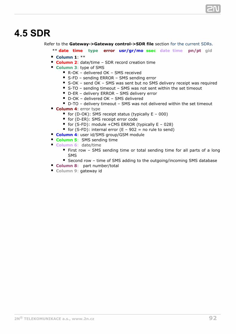
922N TELEKOMUNIKACE a.s., www.2n.cz®
4.5 SDRRefer to the sectionGateway->Gateway control->SDR file for the current SDRs.
** date time type error usr/gr/mo ssec date time pn/pt gid
1Column : **:Column 2 date/time – SDR record creation time:Column 3 type of SMS
R-OK – delivered OK – SMS receivedS-FD – sending ERROR – SMS sending errorS-OK – send OK – SMS was sent but no SMS delivery receipt was requiredS-TO – sending timeout – SMS was not sent within the set timeoutD-ER – delivery ERROR – SMS delivery errorD-OK – delivered OK – SMS deliveredD-TO – delivery timeout – SMS was not delivered within the set timeout
: Column 4 error typefor (D-OK): SMS receipt status (typically E – 000)for (D-ER): SMS receipt error codefor (S-FD): module +CMS ERROR (typically E – 028)for (S-FD): internal error (E – 902 = no rule to send)
:Column 4 user id/SMS group/GSM module:Column 5 SMS sending time :Column 6 date/time
First row – SMS sending time or total sending time for all parts of a longSMSSecond row – time of SMS adding to the outgoing/incoming SMS database
:Column 8 part number/total:Column 9 gateway id

932N TELEKOMUNIKACE a.s., www.2n.cz®
4.6 Available Status MessagesThe following list of statuses is universal and some messages may not be included in
.2N VoiceBlue Next®
GSM Layer Statuses
GSM Layer 2
Name DescriptionWhatFollows
INIT GSM module initialisation start PINREQ
SIM0 Module switch to internal SIM card INIT
PINREQ Module PIN request PINSET
PINSET PIN value sending to module INFO
BLOCKModule blocked temporarily or permanently (see Layer 2information)
INIT
SET-UP Module configuration running IDLE
SLEEP Module sleep running (transition to BLOCK status) BLOCK
NWAIT Awaiting GSM log-in SET-UP
IDLE Rest status, can start/receive call, execute AT&G command CALL/CMD
CALL Call running (call establishing, connected call, call end) IDLE
CMD Communicating with module upon AT&G command IDLE
INFO Information loading from module and SIM card NWAIT
GSM Layer 2 Info for BLOCK
Name Description
(block)Blocked by AT&G command, terminated by module, board or systemreset
Netw-reg GSM log-in refused (not activated SIM), next attempt in 5..60 minutes
Clir-err CLIR activation request refused, next attempt in 2..10 minutes
Mod-err Defective or unconnected GSM module, next attempt in 2 minutes
Pin-err Wrong PIN, permanently in BLOCK status
Sim-err Defective or non- inserted SIM card, next attempt in 2 minutes
Log-out Temporarily logged-out according to parameter X00
Puk-req SIM card requires PUK
(undef) This position of SIM card was not checked by gateway

942N TELEKOMUNIKACE a.s., www.2n.cz®
GSM Layer 3
Name DescriptionNULL Rest status, ready for call
CINIT Request of call to GSM (from Layer 4)
OPROC Call to GSM is connected
CDELIV Call to GSM is ringing
CPRES Indication of call from GSM (from Layer 2)
CRECV Call from GSM is ringing on ISDN interface
IPROC Call from GSM is processed by ISDN interface
ACTIVE Connected call
DISREQ Disconnection request (to Layer 2)
DISIND Indication of disconnection (from Layer 2)
RELREQ Module release for another call (to Layer 2)
OVRECV Reading of DTMF dialling from GSM (from Layer 2)
RELIND Indication of module release (from Layer2)
Link Layer Statuses
Layer 4
Name DescriptionNULL Rest status, ready for call
MORECall request received from GSM or ISDN, awaiting further dialling ortimeout
SET-UP Call request sent to opposite interface
PROC Call request confirmed, awaiting call answer
ACTIVE Connected call
DISC Call disconnection in progress
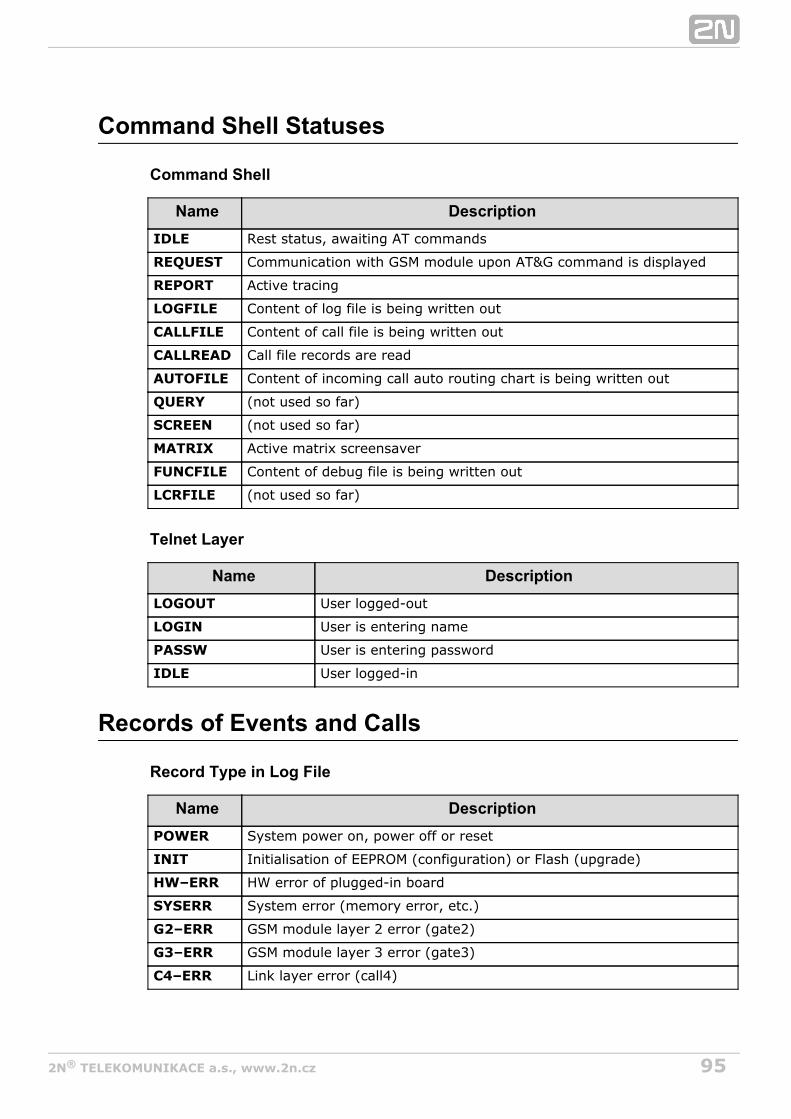
952N TELEKOMUNIKACE a.s., www.2n.cz®
Command Shell Statuses
Command Shell
Name DescriptionIDLE Rest status, awaiting AT commands
REQUEST Communication with GSM module upon AT&G command is displayed
REPORT Active tracing
LOGFILE Content of log file is being written out
CALLFILE Content of call file is being written out
CALLREAD Call file records are read
AUTOFILE Content of incoming call auto routing chart is being written out
QUERY (not used so far)
SCREEN (not used so far)
MATRIX Active matrix screensaver
FUNCFILE Content of debug file is being written out
LCRFILE (not used so far)
Telnet Layer
Name DescriptionLOGOUT User logged-out
LOGIN User is entering name
PASSW User is entering password
IDLE User logged-in
Records of Events and Calls
Record Type in Log File
Name DescriptionPOWER System power on, power off or reset
INIT Initialisation of EEPROM (configuration) or Flash (upgrade)
HW–ERR HW error of plugged-in board
SYSERR System error (memory error, etc.)
G2–ERR GSM module layer 2 error (gate2)
G3–ERR GSM module layer 3 error (gate3)
C4–ERR Link layer error (call4)
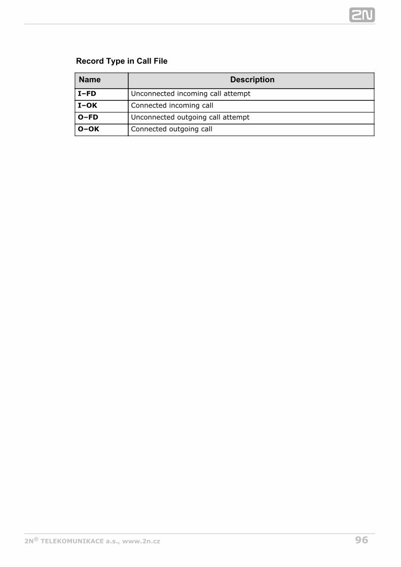
962N TELEKOMUNIKACE a.s., www.2n.cz®
Record Type in Call File
Name DescriptionI–FD Unconnected incoming call attempt
I–OK Connected incoming call
O–FD Unconnected outgoing call attempt
O–OK Connected outgoing call

972N TELEKOMUNIKACE a.s., www.2n.cz®
4.7 StatisticsThe GSM gateway automatically generates statistic data on all outgoing and incomingcalls. These data can be deleted on the user level or though configuration (automaticdeletion on a selected day).
Explanation of columnsPri/grp – type of calls
Reset – date of last reset the statistics
Minutes – number of minutes Hhhh:mm:ss : same number converted to time
Calls – number of calls
SMS – number of sent SMS messages
Reject – number of unconnected calls (no available free GSM module–call rejectedwith cause 41(42))
Failed – number of unconnected calls (rejected by GSM network)
C.offs – number of unconnected calls (terminated by calling party)
Errors – number of unconnected calls (wrong requests – disallowed prefix, etc.)
Red.in – number of connected calls (rerouted to this GSM group)
Redout – number of connected calls (rerouted to another GSM group)
Statistics of outgoing and incoming groups[Statistics of calls in groups]
group (reset) minutes hhhh:mm:ss calls reject failed c.offs errors
––––––––––––––––––––––––––––––––––––––––––––––––––––––––––––––––––––––––––––––
#i1 inc ( 2.01) 0 0:00:00 0 0 0 0 0
#i2 inc ( 2.01) 0 0:00:00 0 0 0 0 0
group (reset) minutes hhhh:mm:ss calls reject failed red.in redout
––––––––––––––––––––––––––––––––––––––––––––––––––––––––––––––––––––––––––––––
#g1 out ( 2.01) 0 0:00:00 0 0 0 0 0
#g2 out ( 2.01) 0 0:00:00 0 0 0 0 0
Statistics of incoming calls on all GSM modules[Statistics of incoming calls on all modules]
network (reset) minutes hhhh:mm:ss calls reject failed c.offs errors
––––––––––––––––––––––––––––––––––––––––––––––––––––––––––––––––––––––––––––––
#vi inc ( 0.00) 0 0:00:00 0 0 0 0 0
#grpinc ( 0.00) 0 0:00:00 0 0 0 0 0

982N TELEKOMUNIKACE a.s., www.2n.cz®
group (reset) minutes hhhh:mm:ss calls reject failed c.offs errors
––––––––––––––––––––––––––––––––––––––––––––––––––––––––––––––––––––––––––––––
#i1 inc ( 2.01) 0 0:00:00 0 0 0 0 0
#i2 inc ( 2.01) 0 0:00:00 0 0 0 0 0
module (reset) minutes hhhh:mm:ss calls reject failed c.offs smses
––––––––––––––––––––––––––––––––––––––––––––––––––––––––––––––––––––––––––––––
#m0 inc ( 2.01) 0 0:00:00 0 0 0 0 0
#m1 inc ( 2.01) 0 0:00:00 0 0 0 0 0
Statistics of outgoing calls on all modules[Statistics of outgoing calls on all modules]
network (reset) minutes hhhh:mm:ss calls reject failed c.offs errors
––––––––––––––––––––––––––––––––––––––––––––––––––––––––––––––––––––––––––––––
#vi out ( 0.00) 0 0:00:00 0 0 0 0 0
#grpout ( 0.00) 0 0:00:00 0 0 0 0 0
group (reset) minutes hhhh:mm:ss calls reject failed red.in redout
––––––––––––––––––––––––––––––––––––––––––––––––––––––––––––––––––––––––––––––
#g1 out ( 2.01) 0 0:00:00 0 0 0 0 0
#g2 out ( 2.01) 0 0:00:00 0 0 0 0 0
module (reset) minutes hhhh:mm:ss calls reject failed c.offs smses
––––––––––––––––––––––––––––––––––––––––––––––––––––––––––––––––––––––––––––––
#m0 out ( 2.01) 0 0:00:00 0 0 0 0 0
#m1 out ( 2.01) 0 0:00:00 0 0 0 0 0
Statistics of calls on specific GSM modules[Statistics of calls on module #0]
sim/dir net/grp minutes hhhh:mm:ss calls reject failed c.offs smses
––––––––––––––––––––––––––––––––––––––––––––––––––––––––––––––––––––––––––––––
#1 inc /1 0 0:00:00 0 0 0 0 0
––––––––––––––––––––––––––––––––––––––––––––––––––––––––––––––––––––––––––––––
#1 out /1 0 0:00:00 0 0 0 0 0
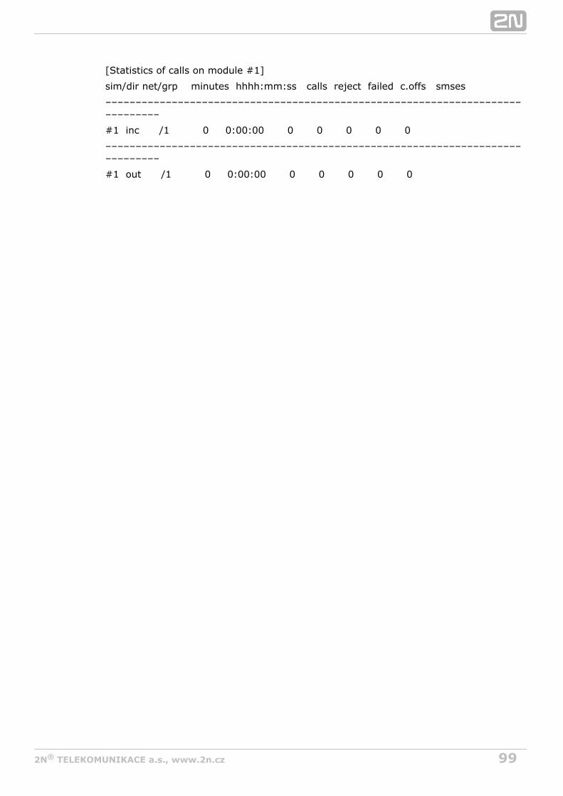
992N TELEKOMUNIKACE a.s., www.2n.cz®
[Statistics of calls on module #1]
sim/dir net/grp minutes hhhh:mm:ss calls reject failed c.offs smses
––––––––––––––––––––––––––––––––––––––––––––––––––––––––––––––––––––––––––––––
#1 inc /1 0 0:00:00 0 0 0 0 0
––––––––––––––––––––––––––––––––––––––––––––––––––––––––––––––––––––––––––––––
#1 out /1 0 0:00:00 0 0 0 0 0

1002N TELEKOMUNIKACE a.s., www.2n.cz®
4.8 Tracing2N VoiceBlue Next® allows for operation tracing (VoIP, SIP, GSM). Tracing isaccessible in one session only at a time, the other tracing requests are rejected withBUSY. With regard to a rather extensive volume of data, we recommend that the
function should be activated before tracing. AnyWrite communication into fileTelnet–supporting terminal (HyperTerminal, Putty, etc.) can be used.
TipYou are advised to synchronise your GSM gateway with the SIPProxy, or a PC before tracing.
AT Command DescriptionAT%S92=x Set the tracing details. Refer to the table below for value X.
AT!R2 Start tracing via the active session.
Any character Terminate tracing.
Layer 3 and 4Status Listing
TimestampWrite–Out
SMP PacketWrite–Out
Layer 2 StatusListing
LCRListing
1 2 4 8 16
The resultant value X is a sum of the required functions (X= timestamps+LCR = 16+2= 18, e.g.).
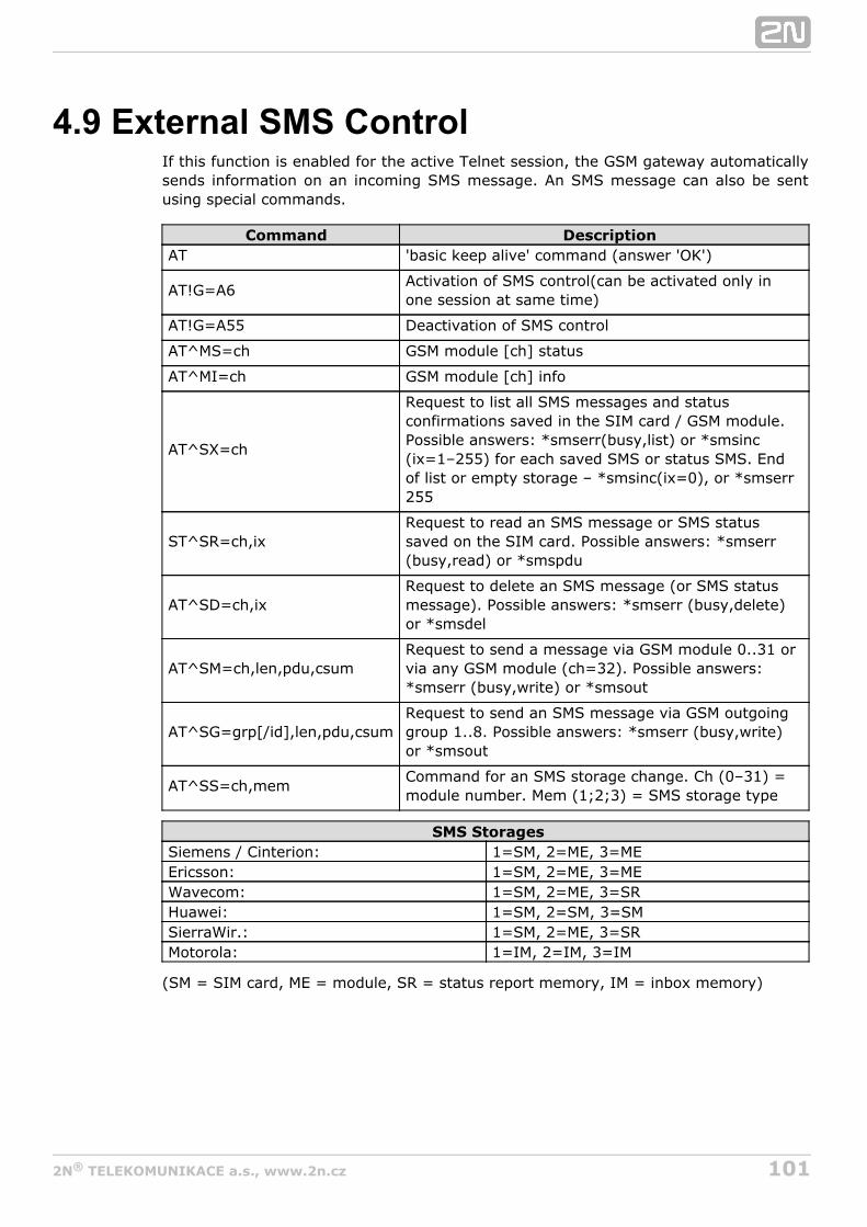
1012N TELEKOMUNIKACE a.s., www.2n.cz®
4.9 External SMS ControlIf this function is enabled for the active Telnet session, the GSM gateway automaticallysends information on an incoming SMS message. An SMS message can also be sentusing special commands.
Command DescriptionAT 'basic keep alive' command (answer 'OK')
AT!G=A6Activation of SMS control(can be activated only inone session at same time)
AT!G=A55 Deactivation of SMS control
AT^MS=ch GSM module [ch] status
AT^MI=ch GSM module [ch] info
AT^SX=ch
Request to list all SMS messages and statusconfirmations saved in the SIM card / GSM module.Possible answers: *smserr(busy,list) or *smsinc(ix=1–255) for each saved SMS or status SMS. Endof list or empty storage – *smsinc(ix=0), or *smserr255
ST^SR=ch,ixRequest to read an SMS message or SMS statussaved on the SIM card. Possible answers: *smserr(busy,read) or *smspdu
AT^SD=ch,ixRequest to delete an SMS message (or SMS statusmessage). Possible answers: *smserr (busy,delete)or *smsdel
AT^SM=ch,len,pdu,csumRequest to send a message via GSM module 0..31 orvia any GSM module (ch=32). Possible answers:*smserr (busy,write) or *smsout
AT^SG=grp[/id],len,pdu,csumRequest to send an SMS message via GSM outgoinggroup 1..8. Possible answers: *smserr (busy,write)or *smsout
AT^SS=ch,memCommand for an SMS storage change. Ch (0–31) =module number. Mem (1;2;3) = SMS storage type
SMS StoragesSiemens / Cinterion: 1=SM, 2=ME, 3=MEEricsson: 1=SM, 2=ME, 3=MEWavecom: 1=SM, 2=ME, 3=SRHuawei: 1=SM, 2=SM, 3=SMSierraWir.: 1=SM, 2=ME, 3=SRMotorola: 1=IM, 2=IM, 3=IM
(SM = SIM card, ME = module, SR = status report memory, IM = inbox memory)
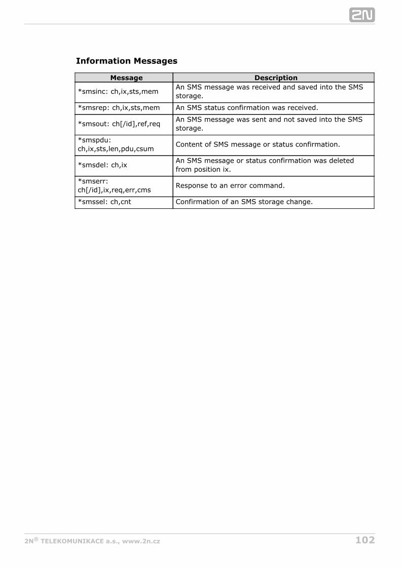
1022N TELEKOMUNIKACE a.s., www.2n.cz®
Information Messages
Message Description
*smsinc: ch,ix,sts,memAn SMS message was received and saved into the SMSstorage.
*smsrep: ch,ix,sts,mem An SMS status confirmation was received.
*smsout: ch[/id],ref,reqAn SMS message was sent and not saved into the SMSstorage.
*smspdu:ch,ix,sts,len,pdu,csum
Content of SMS message or status confirmation.
*smsdel: ch,ixAn SMS message or status confirmation was deletedfrom position ix.
*smserr:ch[/id],ix,req,err,cms
Response to an error command.
*smssel: ch,cnt Confirmation of an SMS storage change.
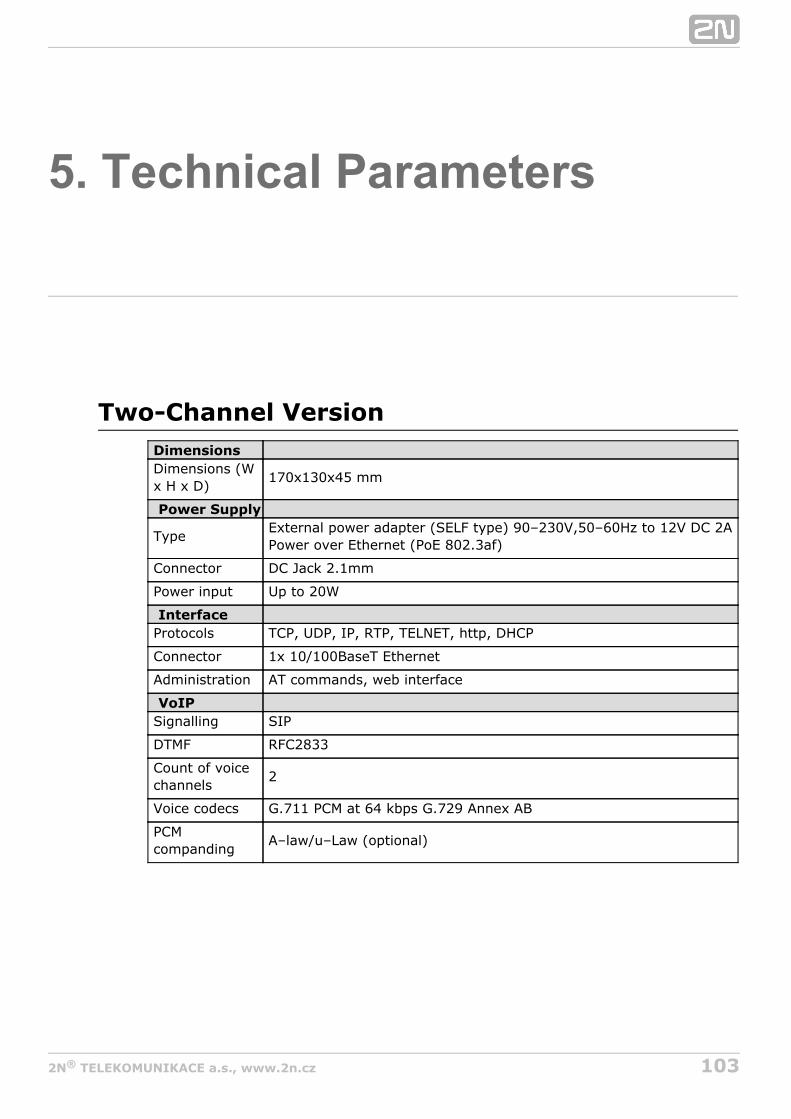
1032N TELEKOMUNIKACE a.s., www.2n.cz®
5. Technical Parameters
Two-Channel VersionDimensions Dimensions (Wx H x D)
170x130x45 mm
Power Supply
TypeExternal power adapter (SELF type) 90–230V,50–60Hz to 12V DC 2APower over Ethernet (PoE 802.3af)
Connector DC Jack 2.1mm
Power input Up to 20W
Interface Protocols TCP, UDP, IP, RTP, TELNET, http, DHCP
Connector 1x 10/100BaseT Ethernet
Administration AT commands, web interface
VoIP Signalling SIP
DTMF RFC2833
Count of voicechannels
2
Voice codecs G.711 PCM at 64 kbps G.729 Annex AB
PCMcompanding
A–law/u–Law (optional)
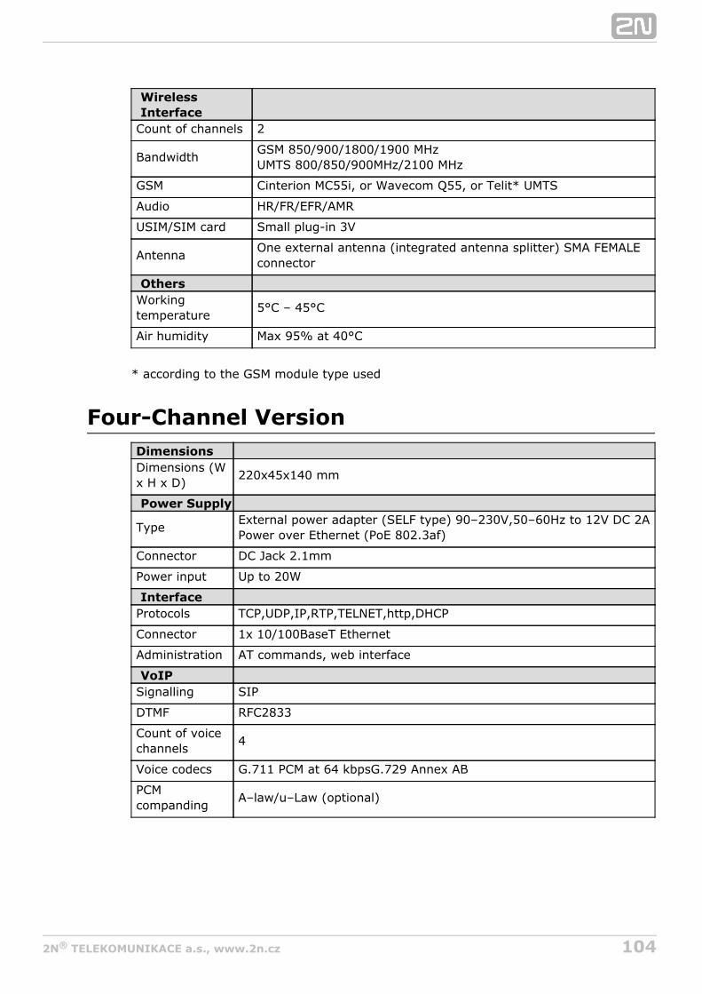
1042N TELEKOMUNIKACE a.s., www.2n.cz®
WirelessInterface
Count of channels 2
BandwidthGSM 850/900/1800/1900 MHzUMTS 800/850/900MHz/2100 MHz
GSM Cinterion MC55i, or Wavecom Q55, or Telit* UMTS
Audio HR/FR/EFR/AMR
USIM/SIM card Small plug-in 3V
AntennaOne external antenna (integrated antenna splitter) SMA FEMALEconnector
Others Workingtemperature
5°C – 45°C
Air humidity Max 95% at 40°C
* according to the GSM module type used
Four-Channel VersionDimensions Dimensions (Wx H x D)
220x45x140 mm
Power Supply
TypeExternal power adapter (SELF type) 90–230V,50–60Hz to 12V DC 2APower over Ethernet (PoE 802.3af)
Connector DC Jack 2.1mm
Power input Up to 20W
Interface Protocols TCP,UDP,IP,RTP,TELNET,http,DHCP
Connector 1x 10/100BaseT Ethernet
Administration AT commands, web interface
VoIP Signalling SIP
DTMF RFC2833
Count of voicechannels
4
Voice codecs G.711 PCM at 64 kbpsG.729 Annex AB
PCMcompanding
A–law/u–Law (optional)

1052N TELEKOMUNIKACE a.s., www.2n.cz®
WirelessInterface
Count of channels 4
BandwidthGSM 850/900/1800/1900 MHzUMTS 800/850/900MHz/2100 MHz
GSM Cinterion MC55i, or Wavecom Q55, or Telit* UMTS
Audio HR/FR/EFR/AMR
USIM/SIM card Small plug-in 3V
AntennaOne external antenna (integrated antenna splitter) SMA FEMALEconnector
Others Workingtemperature
5°C – 45°C
Air humidity Max 95% at 40°C
* according to the GSM module type used
1062N TELEKOMUNIKACE a.s., www.2n.cz®
6. Supplementary Information
This section provides supplementary information on .2N VoiceBlue Next®
Here is what you can find in this section:
6.1 Troubleshooting6.2 List of Abbreviations6.3 Regulations and Directives6.4 General Instructions and Cautions
1072N TELEKOMUNIKACE a.s., www.2n.cz®
6.1 Troubleshooting
For the most frequently asked questions refer to .faq.2n.cz
No LED is shining on .2N VoiceBlue Next®
2N VoiceBlue Next® is disconnected from the power supply. fails to log in to the GSM network.2N VoiceBlue Next®
Check the SIM card.Check the PIN.Check the antenna connection.Select a place with a good GSM signal.
is not communicating with the PC.2N VoiceBlue Next®
Check the Ethernet cable connection and the Ethernet interfacesettings in your PC.
1082N TELEKOMUNIKACE a.s., www.2n.cz®
6.2 List of AbbreviationsFollowing abbreviations are used within manual:
API (Application Programming Interface)ASR (Answer Seizure Ratio)BIOS (Basic Input–Output System)CD (Compact Disc)CDR (Call Data Record)CLIR (Calling Line Identification Restriction)COM (PC serial interface)CPU (Central Processor Unit)DHCP (Dynamic Host Configuration Protocol)DNS (Domain Name Server)DTMF (Dual Tone Multifrequency)eCPU (enhanced CPU)FW (Firmware)GMT (Greenwich Mean Time)GSM (Group Switched Mobile system)GPRS (General Packet Radio Service)GW (Gateway)HW (Hardware)IMEI (International Mobile Equipment Identity)IMSI (International Mobile Subscriber Identity)IP (Internet Protocol)IVR (Interactive Voice Response)LAN (Local Area Network)LED (Light Emitting Diode)NAT (Network Address Translation)PC (Personal Computer)PCB (Printed Circuit Board)PCM (Pulse–code modulation)PIN (Personal Identification Number)PRI (Primary Rate Interface)PUK (Personal Unblocking Key)SB (SIM Board)SC (SIM Client)SIM (Subscriber Identity Module)SIP (Session Initiation Protocol)SMS (Short Message Service)SSH (Secure Shell)SW (Software)TCP (Transmission Control Protocol)UCMD (UDP commands)UDP (User Datagram Protocol)UMTS (Universal Mobile Telecommunication System)UPS (Uninterruptible Power Supply)USSD (Unstructured Supplementary Service Data)VoIP (Voice over Internet Protocol)WAN (Wide Area Network)

1092N TELEKOMUNIKACE a.s., www.2n.cz®
6.3 Regulations and Directives
Europe2N VoiceBlue Next® conforms to the following directives and regulations:
Directive 1999/5/EC of the European Parliament and of the Council, of 9 March 1999 –on radio equipment and telecommunications terminal equipment and the mutualrecognition of their conformity
Directive 2006/95/EC of the European Parliament and of the Council of 12 December2006 on the harmonisation of the laws of Member States relating to electricalequipment designed for use within certain voltage limits
Directive 2004/108/EC of the Council of 15 December 2004 on the harmonisation ofthe laws of Member States relating to electromagnetic compatibility
Commission Regulation (EC) No. 1275/2008, of 17 December 2008, implementingDirective 2005/32/EC of the European Parliament and of the Council with regard toecodesign requirements for standby and off mode electric power consumption ofelectrical and electronic household and office equipment
Directive 2011/65/EU of the European Parliament and of the Council of 8 June 2011 onthe restriction of the use of certain hazardous substances in electrical and electronicequipment
Regulation (EC) No. 1907/2006 of the European Parliament and of the Council of 18December 2006 concerning the Registration, Evaluation, Authorisation and Restrictionof Chemicals (REACH), establishing a European Chemicals Agency, amending Directive1999/45/EC and repealing Council Regulation (EEC) No. 793/93 and CommissionRegulation (EC) No. 1488/94 as well as Council Directive 76/769/EEC and CommissionDirectives 91/155/EEC, 93/67/EEC, 93/105/EC and 2000/21/EC
Directive 2002/96/EC of the European Parliament and of the Council of 27 January2003 on waste electrical and electronic equipment.
Industry CanadaThis Class A digital apparatus complies with Canadian ICES-003. / Cet appareilnumérique de la classe A est conforme a la norme NMB-003 du Canada.
FCCNOTE: This equipment has been tested and found to comply with the limits for a ClassA digital device, pursuant to part 15 of the FCC Rules. These limits are designed toprovide reasonable protection against harmful interference when the equipment isoperated in a commercial environment. This equipment generates, uses, and canradiate radio frequency energy and, if not installed and used in accordance with theinstruction manual, may cause harmful interference to radio communications.Operation of this equipment in a residential area is likely to cause harmful interferencein which case the user will be required to correct the interference at his own expense.
Changes or modifications not approved by the responsible party could void the user’sauthority to operate the equipment.
1102N TELEKOMUNIKACE a.s., www.2n.cz®
6.4 General Instructions and CautionsGeneral Instructions and Cautions
Please read this User Manual carefully before using the product. Follow allinstructions and recommendations included herein.Any use of the product that is in contradiction with the instructions providedherein may result in malfunction, damage or destruction of the product.The manufacturer shall not be liable and responsible for any damage incurred asa result of a use of the product other than that included herein, namely undueapplication and disobedience of the recommendations and warnings incontradiction herewith.Any use or connection of the product other than those included herein shall beconsidered undue and the manufacturer shall not be liable for any consequencesarisen as a result of such misconduct.Moreover, the manufacturer shall not be liable for any damage or destruction ofthe product incurred as a result of misplacement, incompetent installation and/orundue operation and use of the product in contradiction herewith.The manufacturer assumes no responsibility for any malfunction, damage ordestruction of the product caused by incompetent replacement of parts or due tothe use of reproduction parts or components.The manufacturer shall not be liable and responsible for any loss or damageincurred as a result of a natural disaster or any other unfavourable naturalcondition.The manufacturer shall not be held liable for any damage of the product arisingduring the shipping thereof.The manufacturer shall not make any warrant with regard to data loss ordamage.The manufacturer shall not be liable and responsible for any direct or indirectdamage incurred as a result of a use of the product in contradiction herewith or afailure of the product due to a use in contradiction herewith.All applicable legal regulations concerning the product's installation and use aswell as provisions of technical standards on electric installations have to beobeyed. The manufacturer shall not be liable and responsible for damage ordestruction of the product or damage incurred by the consumer in case theproduct is used and handled contrary to the said regulations and provisions.The consumer shall, at its own expense, obtain software protection of theproduct. The manufacturer shall not be held liable and responsible for anydamage incurred as a result of the use of deficient or substandard securitysoftware.The consumer shall, without delay, change the access password for the productafter installation. The manufacturer shall not be held liable or responsible for anydamage incurred by the consumer in connection with the use of the originalpassword.The manufacturer also assumes no responsibility for additional costs incurred bythe consumer as a result of making calls using a line with an increased tariff.

1112N TELEKOMUNIKACE a.s., www.2n.cz®
Electric Waste and Used Battery Pack Handling
Do not place used electric devices and battery packs into municipal waste containers.An undue disposal thereof might impair the environment!
Deliver your expired electric appliances and battery packs removed from them todedicated dumpsites or containers or give them back to the dealer or manufacturer forenvironmental–friendly disposal. The dealer or manufacturer shall take the productback free of charge and without requiring another purchase. Make sure that the devicesto be disposed of are complete.
Do not throw battery packs into fire. Battery packs may not be taken into parts orshirt–circuited either.

1122N TELEKOMUNIKACE a.s., www.2n.cz®
2N TELEKOMUNIKACE a.s.
Modřanská 621, 143 01 Prague 4, Czech Republic
Tel.: +420 261 301 500, Fax: +420 261 301 599
E-mail: [email protected]
Web: www.2n.cz
PR1561 v3.4


