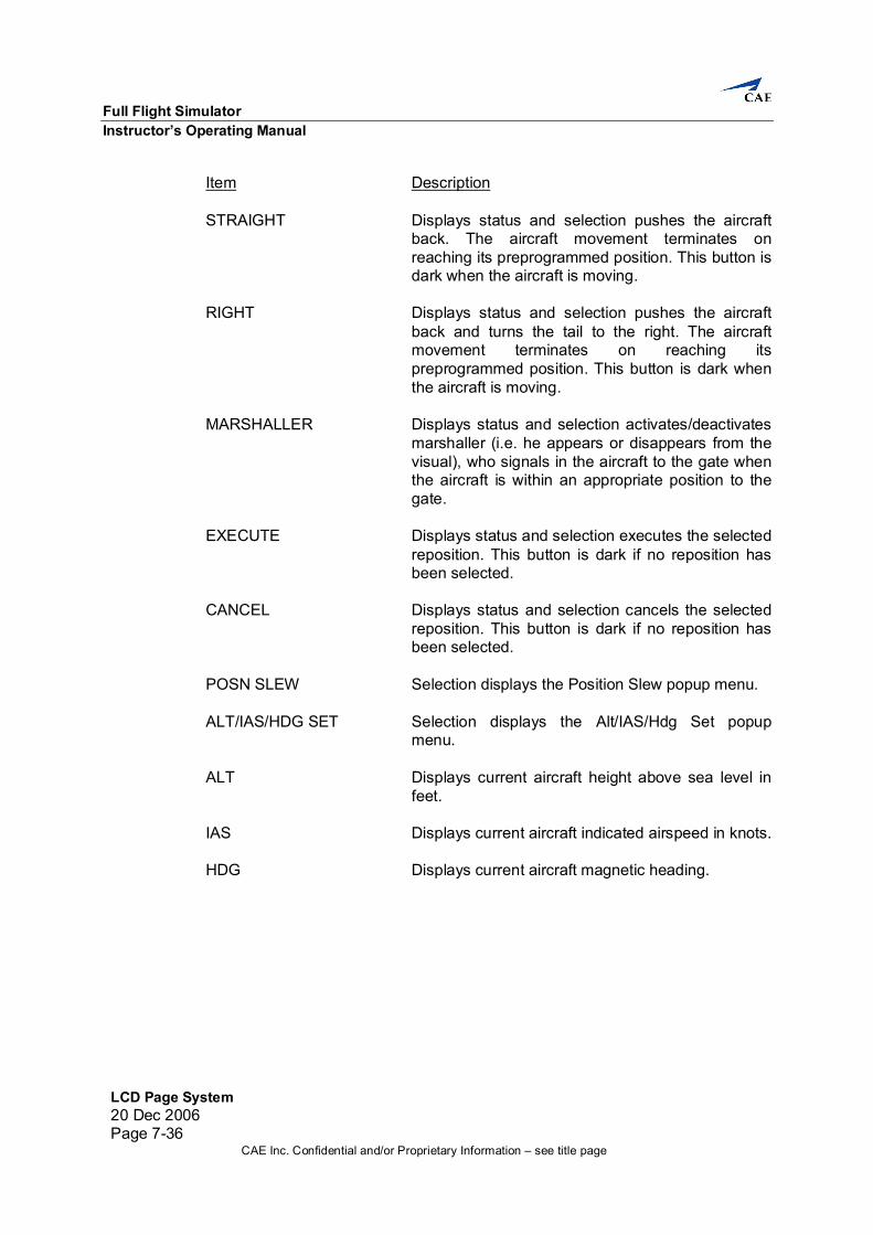
PROPRIETARY NOTICE: This document, including the information contained herein, is confidential and/or proprietary to CAE Inc., and shall not be reproduced or disclosed in whole or in part, or used for any purpose whatsoever without the prior written authorization of CAE Inc. 20 Dec 2006 TPD 18027 B737 Full Flight Simulator Instructor’s Operating Manual
Transcript
PROPRIETARY NOTICE: This document, including the information contained herein, is confidential and/or proprietary to CAE Inc., and shall not be reproduced or disclosed in whole or in part, or used for any purpose whatsoever without the prior written authorization of CAE Inc.
20 Dec 2006 TPD 18027
B737 Full Flight Simulator
Instructor’s Operating Manual
CAE Inc. Confidential and/or Proprietary Information – see title page
Contact Information Customer Support Web Site: custserv.cae.com Telephone: (514) 341-6780 Fax: (514) 341-7699 Mailing Address: CAE Inc. 8585 Cote de Liesse Saint-Laurent, Quebec Canada H4T 1G6 Trademarks and/or registered trademarks of CAE Inc. and/or its affiliates include but are not limited to CAE, CAE & Design, CAE Atmos, Atmos, CAE Exos, Exos, CAE Ionos, Ionos, CAE Lithos, Lithos, CAE Mesos, Mesos, CAE Stratos, Stratos, CAE Tropos, Tropos, CAE ROSE, ROSE, CAELIB, CAE Medallion, Medallion, CAE Medallion-S, Medallion-S, CAE SIM XXI, SIM XXI, CAE Simfinity, Simfinity, CAE ITEMS, ITEMS, CAE RAVE, RAVE, CAE STRIVE, STRIVE, CAE TIGERS, TIGERS, and ROTORSIM. All other brands and product names are trademarks or registered trademarks of their respective owners. All logos, tradenames and trademarks referred to and used herein remain the property of their respective owners and may not be used, changed, copied, altered, or quoted without the written consent of the respective owner. All rights reserved.
Instructor’s Operating Manual Safety Precautions
Safety Precautions20 Dec 2006
Page iCAE Inc. Confidential and/or Proprietary Information – see title page
Safety Precautions The following general safety notices supplement the specific warnings and cautions appearing elsewhere in this manual. There are recommended precautions that must be understood and applied during operation and maintenance of the equipment covered herein. Should situations arise that are not covered by safety precautions given consult the proper local authority. (1) Under no circumstances should a person operate or maintain this equipment without the
immediate presence or assistance of another person capable of rendering aid. (2) Personnel working with or near high voltages must be familiar with modern methods of
resuscitation. In the event of electrical shock, always:
(a) Remove power.
(b) Administer first aid treatment.
(c) Summon assistance. (3) In the event of fire, carry out the procedures provided in your local fire code. (4) All operation and maintenance personnel should be familiar with the location and
function of the emergency shutdown switches. They should also be familiar with the emergency procedures needed to remove power from damaged equipment.
(5) The simulator has voltages that are dangerous and may be fatal if contacted by
operation or maintenance personnel. (6) Do not energize equipment unless safety grounds have been established; failure to do
so may result in electrical shock to the operator. (7) Do not place a finger over a leak to determine the extent of a leakage. High pressure
spray can puncture the skin and enter the bloodstream. High pressure spray is potentially explosive.
(8) Spilled hydraulic fluid is a safety hazard and must be wiped up immediately. (9) Before starting the motion system, ensure that the area around the simulator envelope is
clear of personnel and that all loose objects are secured. (10) If, at any time, a safety hazard is detected, it is the responsibility of the individual to
report the hazard to ensure it is corrected. (11) All personnel in the flight compartment are to be fastened with seat belts. (12) Do not adjust the seat(s) when the motion system is on.
Instructor’s Operating Manual List of Effective Pages
List of Effective Pages20 Dec 2006
Page iiiCAE Inc. Confidential and/or Proprietary Information – see title page
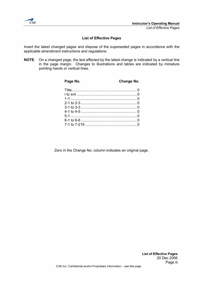
List of Effective Pages Insert the latest changed pages and dispose of the superseded pages in accordance with the applicable amendment instructions and regulations: NOTE: On a changed page, the text affected by the latest change is indicated by a vertical line
in the page margin. Changes to illustrations and tables are indicated by miniature pointing hands or vertical lines.
Page No. Change No. Title...............................................................0 i to xvii ..........................................................0 1-1 ................................................................0 2-1 to 2-3 ......................................................0 3-1 to 3-3 ......................................................0 4-1 to 4-5 ......................................................0 5-1 ................................................................0 6-1 to 6-6 ......................................................0 7-1 to 7-219 ..................................................0
Zero in the Change No. column indicates an original page.
Instructor’s Operating Manual Table of Contents
Table of Contents20 Dec 2006
Page vCAE Inc. Confidential and/or Proprietary Information – see title page
Table of Contents Section/Title Page
List of Effective Pages ................................................................................................................ iii
Table of Contents ........................................................................................................................v
List of Illustrations....................................................................................................................... ix
List of Tables.............................................................................................................................. xi
List of Terms and Abbreviations.................................................................................................xiii
General ....................................................................................................................................1-1 1. Introduction.....................................................................................................................1-1
1.1 Reference .........................................................................................................1-1 1.2 Main Sections....................................................................................................1-1
Safety Features ........................................................................................................................2-1 2. Introduction.....................................................................................................................2-1
2.1 Emergency Cutoff Switches...............................................................................2-1 2.1.1 Motion System Cutoff Switches....................................................................2-1 2.1.2 Electrical Power System Emergency Cutoff..................................................2-1
2.2 Crew Access .....................................................................................................2-1 2.2.1 Emergency Operation of Accessway............................................................2-1
2.3 Rope Ladder .....................................................................................................2-2 2.4 Smoke and Heat Detection System....................................................................2-2 2.5 Emergency Lighting...........................................................................................2-3 2.6 Emergency Power Source .................................................................................2-3 2.7 Fire Suppression System (Optional)...................................................................2-3
Instructor Station Configuration.................................................................................................3-1 3. Introduction.....................................................................................................................3-1
3.1 Instructor Station Hardware Configuration..........................................................3-2
Full Flight Simulator Instructor’s Operating Manual
Table of Contents 20 Dec 2006 Page vi
CAE Inc. Confidential and/or Proprietary Information – see title page
Startup and Shutdown ..............................................................................................................4-1 4. Introduction.....................................................................................................................4-1
4.1 Daily Site Inspections ........................................................................................4-1 4.2 Startup ..............................................................................................................4-2
4.2.1 Control Loading System Startup...................................................................4-2 4.2.2 Motion System Startup.................................................................................4-2 4.2.3 Instructor Operating Station Touch Screen...................................................4-3
4.3 Shutdown..........................................................................................................4-4 4.3.1 Control Loading System Shutdown ..............................................................4-4 4.3.2 Motion System Shutdown ............................................................................4-5 4.3.3 Instructor Operating Station Touch Screen...................................................4-5
7.2.1 Regular and Lesson Page Color Logic .........................................................7-3 7.2.2 Malfunction Pages Color Logic.....................................................................7-3 7.2.3 Map Color Logic ..........................................................................................7-4 7.2.4 Approach Plots Color Logic..........................................................................7-4 7.2.5 Runway Plots Color Logic ............................................................................7-4
7.6 Index Pages ....................................................................................................7-14 7.6.1 Master Index..............................................................................................7-14 7.6.2 Malfunction Index.......................................................................................7-17 7.6.3 Lesson Plan Index .....................................................................................7-18
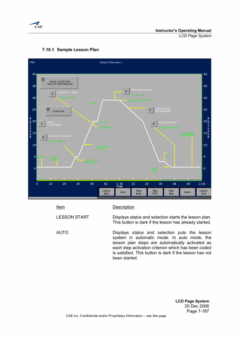
7.10 Lesson Plan Pages........................................................................................7-185 7.10.1 Sample Lesson Plan ..........................................................................7-187
7.12 Help Pages ...................................................................................................7-210
Instructor’s Operating Manual List of Illustrations
List of Illustrations20 Dec 2006
Page ixCAE Inc. Confidential and/or Proprietary Information – see title page
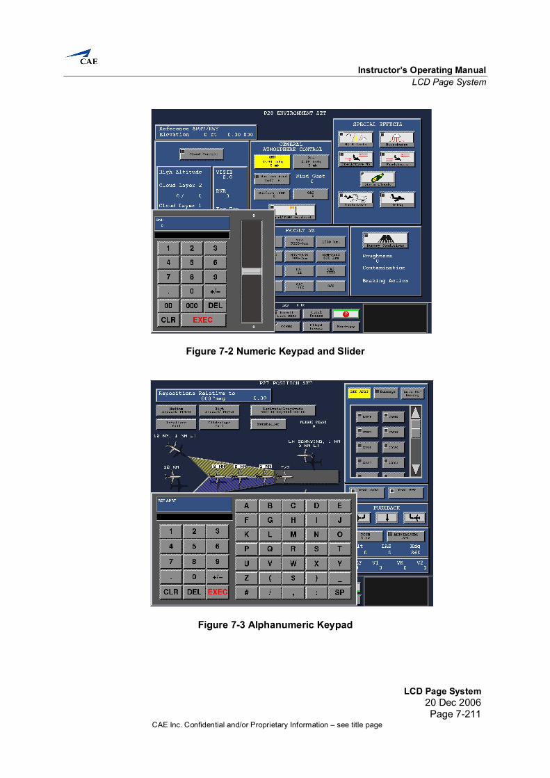
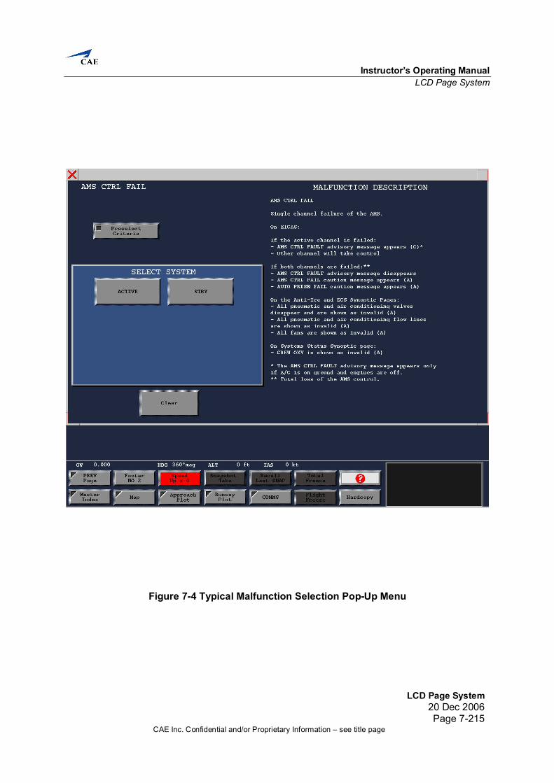
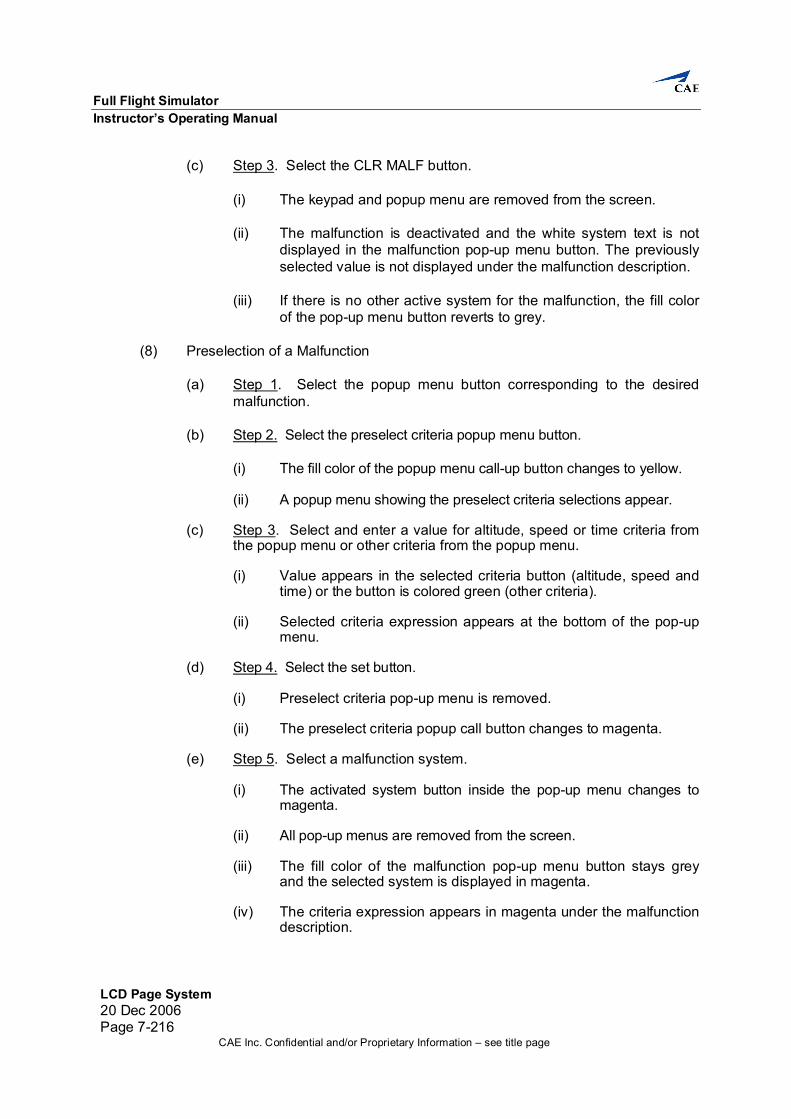
List of Illustrations Figure/Title Page Figure 3-1 Forward Facing IOS.............................................................................................3-3 Figure 6-1 Emergency Shutdown Panel................................................................................6-1 Figure 6-2 Communications Facility Panel ............................................................................6-3 Figure 6-3 Lighting Control Panel..........................................................................................6-4 Figure 6-4 Accessway Control Panel ....................................................................................6-5 Figure 6-5 Temperature Control Panel..................................................................................6-6 Figure 7-1 LCD Layout..........................................................................................................7-1 Figure 7-2 Numeric Keypad and Slider..............................................................................7-211 Figure 7-3 Alphanumeric Keypad......................................................................................7-211 Figure 7-4 Typical Malfunction Selection Pop-Up Menu....................................................7-215
Instructor’s Operating Manual List of Tables
List of Tables20 Dec 2006
Page xiCAE Inc. Confidential and/or Proprietary Information – see title page
List of Tables Table/Title Page Table 4-1 Control Loading System Startup Procedure ..........................................................4-2 Table 4-2 Motion System in Normal Mode Startup Procedure (IOS) .....................................4-3 Table 4-3 Control Loading System Shutdown Procedure (IOS).............................................4-4 Table 4-4 Motion System Shutdown Procedure (IOS)...........................................................4-5 Table 7-1 Map Symbology ....................................................................................................7-5
Instructor’s Operating Manual List of Terms and Abbreviations
List of Terms and Abbreviations20 Dec 2006
Page xiiiCAE Inc. Confidential and/or Proprietary Information – see title page
List of Terms and Abbreviations ac alternating current ACARS Aircraft Communications Addressing and Reporting System ACIP ac Input ACOP ac Output ADC Analog-to-Digital Converter ADF Automatic Direction Finder ADIO Analog/Digital Input/Output AI Analog Inputs AIM Acknowledgment, ISO Alphabet no. 5 and Maintenance AIO Analog Input/Output AIOI ARINC 429 input/output interface AIP Analog Input AIRO Analog Input Reference Output AGL Above Ground Level AM Amplitude Modulated amp Ampere AOM Analog Output Module AOP Analog Output ASCII American Standard Code for Information Exchange ASL Above Sea Level ATC Air Traffic Control ATIS Automated Terminal Information Service ATO Address Time-Out A/W Accessway BCD Binary Coded Decimal BFO Beat Frequency Oscillator BI Bus Identification BPS beats per second BU Buffer Unit B/W Black and White CAL Instrument Calibration Utility CAPT Computer Assisted Procedures Trainer CB Circuit Breaker CCD Charge Coupled Device CCU C-Bus Check Utility CDB Common Database CMS Central Monitoring System CO2 Carbon Dioxide Comp. Computers Corp. Corporation CPU Central Processing Unit CRA Coefficient RAM Address
Full Flight Simulator Instructor’s Operating Manual
List of Terms and Abbreviations 20 Dec 2006 Page xiv
CAE Inc. Confidential and/or Proprietary Information – see title page
CRT Cathode Ray Tube CS Card Select CSMA/CD Carrier Sense Multiple Access with Collision Detection CSS Cockpit Simulator System CTS Computerized Test System CVR Cockpit Voice Recorder CWE CAELIB Working Environment DAC Digital-to-Analog Converter DACW DAC Write DASIU Digital Audio System Interface Unit DAST Direct Analog Storage Technology dc direct current DCB Data Control Block DCR Data Control Register DFC Digital Flight Controls DIN Deutsche Industrie Normen DIO Digital Input/Output DIO-CB Digital Input/Output Circuit Breaker DIP Digital Input DMC Datapath® C Microprocessor Controller DMM Digital Multi-Meter DN1 Digital Control Cabinet DOP Digital Output DOP Discrete Output DOR Digital Output Relay DPA Dual Power Amplifier DRA Data RAM Address DSG Digital Signal Generator DSP Digital Signal Processor DTO Data Time-Out DV Digital Voice DVM Digital Voltmeter EFCS Electronic Flight Control System EICAS Engine Instrument and Crew Alert System EL Electroluminescent Elec. Electronics EMI Electromagnetic Interference EPO Emergency Power Off ESU Electronic Service Unit F/C Flight Compartment FC Flight Compartment FDCC Fiber-Optic Digital Chassis Controller FDDI Fiber-Optic Distributed Digital Interface
Instructor’s Operating Manual List of Terms and Abbreviations
List of Terms and Abbreviations20 Dec 2006
Page xvCAE Inc. Confidential and/or Proprietary Information – see title page
FFIOS Forward-Facing Instructor Operating System FFS Full Flight Simulator FIFO First-In, First-Out FIR Finite Impulse Response FIRCTL FIR Control FMAST Flight Management and System Trainer FMC Flight Management Computer FOV Field of View FP Feature Processor FPMC Floating Point Motion Controller FSK Frequency Shift Keying FTD Flight Training Device FWS Flight Warning System GAL Generic Array Logic GB Giga Byte GBYTE Giga Byte GPWS Ground Proximity Warning System HPS Hydraulic Power Supply HP Hewlett Packard HPU Hydraulic Power Unit HS High Speed Hz Hertz I/O Input/Output IATA International Air Transport Association IC Integrated Circuit ID Identification IDS Integrated Diagnostic System IGW Increased Gross Weight Int’l International IOS Instructor Operating System IP Internet Protocol IPE Integral Position Equipment KYBD Keyboard LAHSO Land and Hold Short Operations LAN Local Area Network LCD Liquid Crystal Display LED Light Emitting Diode LRU Line Replaceable Unit LSB Least Significant Bit LVOS Light-to-Voltage Optical Sensor
Full Flight Simulator Instructor’s Operating Manual
List of Terms and Abbreviations 20 Dec 2006 Page xvi
CAE Inc. Confidential and/or Proprietary Information – see title page
MA Mechanical Assembly MAC MAXVUE™ Autocal Controller MAIB MAXVUE™ Autocal Integrated Board MCL Motion and Control Loading MCU Master Control Unit Misc. Miscellaneous MMU Memory Management Unit MOB Multiple Output Board MOS Metal-Oxide Semi-conductor MSB Most Significant Bit MSV Main Switch-Visual MTFAA Motion Test FAA MTP Motion Test Program NMI Non-Maskable Interrupt OEM Original Equipment Manufacturer OSI Open System Interconnection PA Public Address PAL Programmable Array Logic PC Programmable Controller PC Personal Computer PCB Printed Circuit Board PDM Pulse Duration Modulation PE Position Error PHU Projector Head Unit PIC Programmable Interrupt Controller PIT Programmable Interval Timer PP2 Pixel Processor type 2 PROM Programmable Read Only Memory PSC Parallel-to-Serial Converter PSCD Procurement Specification Control Drawing PTT Press-to-Talk QTG Qualification Test Guide RACU Remote Alignment and Control Unit RAM Rapid Access Maintenance RCP Radio Control Panel RFT Ready for Training RPM Rotations per minute RTD Resistance Temperature Detector
Instructor’s Operating Manual List of Terms and Abbreviations
List of Terms and Abbreviations20 Dec 2006
Page xviiCAE Inc. Confidential and/or Proprietary Information – see title page
SAH Sample and Hold SC-bus Super Chassis Bus SOP Synchro Output Spec. Specification TCAS Traffic Alert and Collision Avoidance System TCP Transmission Control Protocol temp. Temperature TOP Torquer Output TPD Technical Publications Department TSD Time-Shared Data UPS Uninterruptible Power Supply V Volts Vac Volts of alternating current VAE Voice Alteration Effect VCP Video Cassette Player VCR Video Cassette Recorder Vdc Volts of direct current VESDA® Very Early Smoke Detection Apparatus VHF Very High Frequency VHS Very High Speed VOR VHF Omni-Range VP Vocal Player VPC Video Player Card
Instructor’s Operating Manual General
General20 Dec 2006
Page 1-1CAE Inc. Confidential and/or Proprietary Information – see title page
General 1. Introduction
The Instructor’s Operating Manual is one manual in a set of CAE-supplied hardware documentation that supports the operation and maintenance of the Boeing 737 Full Flight Simulator.
1.1 Reference
The following reference documents for the Boeing 737 Full Flight Simulator apply herein:
(1) Part 1 is a general introduction. (2) Part 2 outlines the safety features. (3) Part 3 outlines the instructor station configuration. (4) Part 4 describes the startup and shutdown procedures. (5) Part 5 describes the flight readiness checks. (6) Part 6 describes the individual instructor station panels. (7) Part 7 describes the LCD page system.
NOTE: All LCD pages included in this IOM are snapshots of LCD pages at Ready for Training (RFT).
Instructor’s Operating Manual Safety Features
Safety Features20 Dec 2006
Page 2-1CAE Inc. Confidential and/or Proprietary Information – see title page
Safety Features 2. Introduction
The instructor station and surrounding areas are provided with the following safety equipment and systems.
2.1 Emergency Cutoff Switches
2.1.1 Motion System Cutoff Switches The motion system can be de-pressurized in less than 30 seconds when it is shutdown either by switching off the motion system (normal operation) or by selecting one of the hydraulic cutoff switches in the off position. These switches are guarded and located at the instructor console, in the maintenance areas and in the forward simulated area. The switch(es) in the simulated area blend with the appearance of the cockpit and are accessible to the flight crew. Operation of any of the switches cuts power from all hydraulic pumps, causes the motion system to make an orderly transition to the rest position, and deactivates the flight controls.
2.1.2 Electrical Power System Emergency Cutoff An electrical power emergency cutoff system is provided. Emergency cutoff switches are easily accessible and located at the IOS and P1 cabinet. Activation of any EPO switch shall deactivate the main power input.
2.2 Crew Access When the simulator flight compartment comes to the rest position, the accessway automatically swings into position against the exit platform at the rear of the flight compartment.
2.2.1 Emergency Operation of Accessway In the event of a complete power failure, the motion platform automatically retracts to the rest position and the accessway lowers. The accessway is driven up and down by means of a dc motor. Power for the dc motor is supplied from an emergency power source. As an alternative, it is possible to unlatch the drive mechanism and manually lower the accessway. If any of the emergency cutoff switches are operated, the power to the drive mechanism of the accessway is maintained and is operable from a switch located at the flight compartment exit.
Full Flight Simulator Instructor’s Operating Manual
Safety Features 20 Dec 2006 Page 2-2
CAE Inc. Confidential and/or Proprietary Information – see title page
2.3 Rope Ladder If the accessway does not function properly, a rope escape ladder is provided for exiting the simulator. The rope escape ladder is located under the floor at the rear of the simulator. To use the rope escape ladder, open the access door and unroll the escape ladder over the middle railing rung or lower panel on the back of the flight compartment. NOTE: If there is no immediate danger, wait for the maintenance crew to provide
a solid ladder before using the rope ladder.
2.4 Smoke and Heat Detection System A Very Early Smoke Detection Apparatus (VESDA®) system detects invisible molecules generated during the precombustion stages of an incipient fire. This system continuously samples air from the equipment environment through a high efficiency aspirator. The detection unit signal is then processed and, depending on the smoke level, can be programmed to indicate: (1) Alert: to investigate detection of something out of the ordinary (2) Action: to initiate emergency procedures for a potential fire (3) Fire: actual fire condition. Air sampled through pipes installed inside the CAE interface cabinets and simulator flight compartment is routed via tubing to the VESDA® system detector where the air sample is analyzed. The self-contained VESDA® unit is installed in the computer room. Automatic deactivation of simulator power by the power control cabinet (P1), audible warning, and indication of the effected zone on power control cabinet monitor screen as well as on the detector control unit are provided. The VESDA® detection system is equipped with a component failure detection and self-test capability. Alarm and other monitor signals are available for connection to the building fire detection control panel from the P1 cabinet. The system operates via a purchaser-supplied facility power source independent from normal simulator power. The HPS is monitored using a conventional smoke detector system.
Instructor’s Operating Manual Safety Features
Safety Features20 Dec 2006
Page 2-3CAE Inc. Confidential and/or Proprietary Information – see title page
2.5 Emergency Lighting Emergency lighting is provided in the flight compartment and at the entry platform. The lighting is powered from the emergency power source and switches on automatically in the event of a complete loss of building power when the simulator is in operation.
2.6 Emergency Power Source All emergency operations described are powered from a standby CAE-supplied line-rechargeable battery power pack. The pack automatically recharges when normal power is available.
2.7 Fire Suppression System (Optional) The fire suppression systems consist of a CO2 fire extinguisher in the instructor's area and an automatic suppression system using a chemical agent. This automatic fire suppression system is often comprised of a control panel, alarm devices and cylinders for chemical agent. For more information, refer to 115-9 (Safety) of the Maintenance Manual.
Instructor’s Operating Manual Instructor Station Configuration
Instructor Station Configuration20 Dec 2006
Page 3-1CAE Inc. Confidential and/or Proprietary Information – see title page
Instructor Station Configuration 3. Introduction
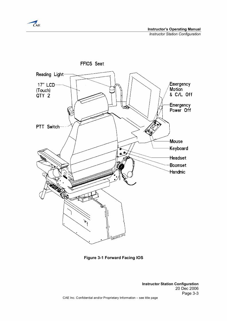
A typical CAE forward-facing IOS station is designed to assist the instructor in monitoring all aspects of crew performance in the simulator (see Figure 3-1). Two touch-sensitive color Liquid Crystal Displays (LCDs) are mounted on the Instructor Seat’s workstation which allow the instructor to move his seat forward behind the crew and easily monitor crew performance. The station incorporates the design features necessary to tailor it to the operational needs of the user. The state-of-the-art hardware and software are utilized to make the station a powerful and user friendly human-computer interface. A facility is provided at the sidewall to store books and to house various controls that are not continually required by the instructor. The basic components of the station include: (1) Two 17" Touch-Sensitive High-resolution Color LCDs. The LCDs use a flexible system
of high-resolution graphics, icons, scrolling, graphic slew/slider controls, context sensitive popup menus and windowing techniques to simplify and optimize the IOS pages, providing the user with an easy-to-use environment. The flight deck responds within a second of instructor input.
To allow the instructor to structure a training exercise before commencing the simulator session, a powerful lesson plan editor is provided. With lesson plans, the entire simulator controls and monitor functions may be preprogrammed and automatically executed under instructor control during the training session.
(2) Seats.
(a) Instructor Seat. The instructor seat is positioned to optimize the instructor’s view of trainee actions. Equipped with armrests and a lap belt, the instructor seat has adjustments such as height and position along the track which provide comfort and safety while the instructor remains seated.
(b) Observer Seat. The observer seat is a non-aircraft seat equipped with armrests
and a lap belt. It is mounted on a track to allow fore and aft movement, and is capable of height adjustment. The observer seat is mechanically controlled.
(c) Second Observer Seat. The second observer seat is a non-aircraft type seat. The
seat is a non-adjustable folding jumpseat and is maintained in a fixed position at the rear of the flight compartment.
Full Flight Simulator Instructor’s Operating Manual
Instructor Station Configuration 20 Dec 2006 Page 3-2
CAE Inc. Confidential and/or Proprietary Information – see title page
3.1 Instructor Station Hardware Configuration The instructor station (see Figure 3-1) consists of the following:
• Simulator controls for emergency motion and control loading stop; emergency
power off • Communications facility – audio jack panel mounted at the back of the instructor
seat and a Press-To-Talk (PTT) switch provided on the station • Lighting controls for the flight compartment and a reading light for the IOS station • Service Outlet panel • Accessway control • Temperature control. The panels on the instructor station are described in section 6.
Instructor’s Operating Manual Instructor Station Configuration
Instructor Station Configuration20 Dec 2006
Page 3-3CAE Inc. Confidential and/or Proprietary Information – see title page
Figure 3-1 Forward Facing IOS
Instructor’s Operating Manual Startup and Shutdown
Startup and Shutdown20 Dec 2006
Page 4-1CAE Inc. Confidential and/or Proprietary Information – see title page
Startup and Shutdown 4. Introduction
The following section includes a startup and shutdown checklist for the motion and control loading on the IOS. For a more detailed description of the safety precautions, and startup and shutdown procedures, refer to the Maintenance Operating Manual.
4.1 Daily Site Inspections Before prestart, tour the simulator site and check the following: (1) On the projector maintenance deck atop the flight compartment, if equipped with
a hinged rear railing, ensure that that it is in the “flight” position. The railing is in the flight position when it is canted forward, and should be secured in this position using the quick-release pins located near its pivot points. While on the projector maintenance deck, check to ensure that no maintenance equipment has been left behind.
(2) In the mirror cavity, ensure that no maintenance equipment has been left behind and that no service personnel are inside.
(3) Ensure that all doors, covers and hatches on the flight compartment are secured in the closed position.
(4) Ensure that the doors on all cabinets are closed.
(5) Ensure that all personnel and maintenance equipment (ladders, scaffolding, forklifts, etc.) are outside the motion envelope of the simulator.
(6) Check the status of the following battery backup and UPS systems.
Full Flight Simulator Instructor’s Operating Manual
Startup and Shutdown 20 Dec 2006 Page 4-2
CAE Inc. Confidential and/or Proprietary Information – see title page
4.2 Startup
4.2.1 Control Loading System Startup WARNING: BEFORE STARTING THIS PROCEDURE AND WHILE THE
SYSTEM IS IN OPERATION, THE TECHNICIAN MUST ENSURE THAT THE CREW IS CLEAR OF THE FLIGHT CONTROLS.
Table 4-1 lists the steps to startup the control loading system in the NORMAL mode. This procedure will start up the flight controls (control loading) from the IOS. NOTE: During these procedures, various warnings or failures may be
annunciated; they must be cleared before the procedure is continued.
Table 4-1 Control Loading System Startup Procedure Step Location Check(s)/Action(s) Expected
Input(s)/Output(s)
1 IOS In the footer of the IOS page, perform the following:
2 IOS Check C/L button. Reads READY.
3 IOS Press C/L button. Starts flashing while indicating STARTING; changes to ON and remains illuminated.
4.2.2 Motion System Startup The following paragraphs describe the procedures to start up the motion system in normal mode (see Table 4-2). In normal mode the motion system can be engaged only from the IOS control panel. NOTE: Prior to engaging the motion system, the hydraulic power supply must
be operational and control loading must be ON. The M4 cabinet must be on with the simulator loaded and running.
WARNING: BEFORE STARTING THIS PROCEDURE AND WHILE THE
SYSTEM IS IN OPERATION, THE TECHNICIAN MUST ENSURE THAT:
(1) ALL PERSONNEL ARE CLEAR OF THE MOTION BASE. (2) ANY LOOSE EQUIPMENT IS REMOVED OR SAFELY
STOWED.
Instructor’s Operating Manual Startup and Shutdown
Startup and Shutdown20 Dec 2006
Page 4-3CAE Inc. Confidential and/or Proprietary Information – see title page
(3) ALL PERSONNEL IN THE FLIGHT COMPARTMENT ARE
TO BE FASTENED WITH SEAT BELTS.
(4) THE ACCESSWAY GATE, FC DOOR AND ALL BAY DOORS ARE CLOSED.
Table 4-2 Motion System in Normal Mode Startup Procedure (IOS) Step Location Check(s)/Action(s) Expected
Input(s)/Output(s)
1 IOS On the IOS SIMULATOR CONTROLS page perform the following:
2 IOS Check MOTION button. Reads READY
3 IOS Press MOTION button.. Starts flashing while indicating STARTING; changes to ON and remains illuminated.
NOTE: Cooling pump motor must be ON.
Another person will observe the following actions outside the simulator.
4 Audible alarm. Sounds until the motion system rises to the neutral position
5 Drawbridge warning light (located near the drawbridge entrance.
Flashes red
6 Motion warning lights (located under the motion platform).
Flashes red
7 Accessway. Accessway is raised and system is pressurized.
8 Motion platform. Rises to the neutral position (mid travel)
4.2.3 Instructor Operating Station Touch Screen To turn on the IOS touch screen, locate and turn on the power switch. Power indicator should illuminate.
Full Flight Simulator Instructor’s Operating Manual
Startup and Shutdown 20 Dec 2006 Page 4-4
CAE Inc. Confidential and/or Proprietary Information – see title page
4.3 Shutdown
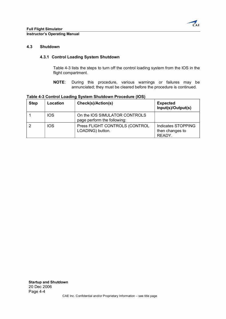
4.3.1 Control Loading System Shutdown Table 4-3 lists the steps to turn off the control loading system from the IOS in the flight compartment. NOTE: During this procedure, various warnings or failures may be
annunciated; they must be cleared before the procedure is continued.
Table 4-3 Control Loading System Shutdown Procedure (IOS) Step Location Check(s)/Action(s) Expected
Input(s)/Output(s)
1 IOS On the IOS SIMULATOR CONTROLS page perform the following:
Instructor’s Operating Manual Startup and Shutdown
Startup and Shutdown20 Dec 2006
Page 4-5CAE Inc. Confidential and/or Proprietary Information – see title page
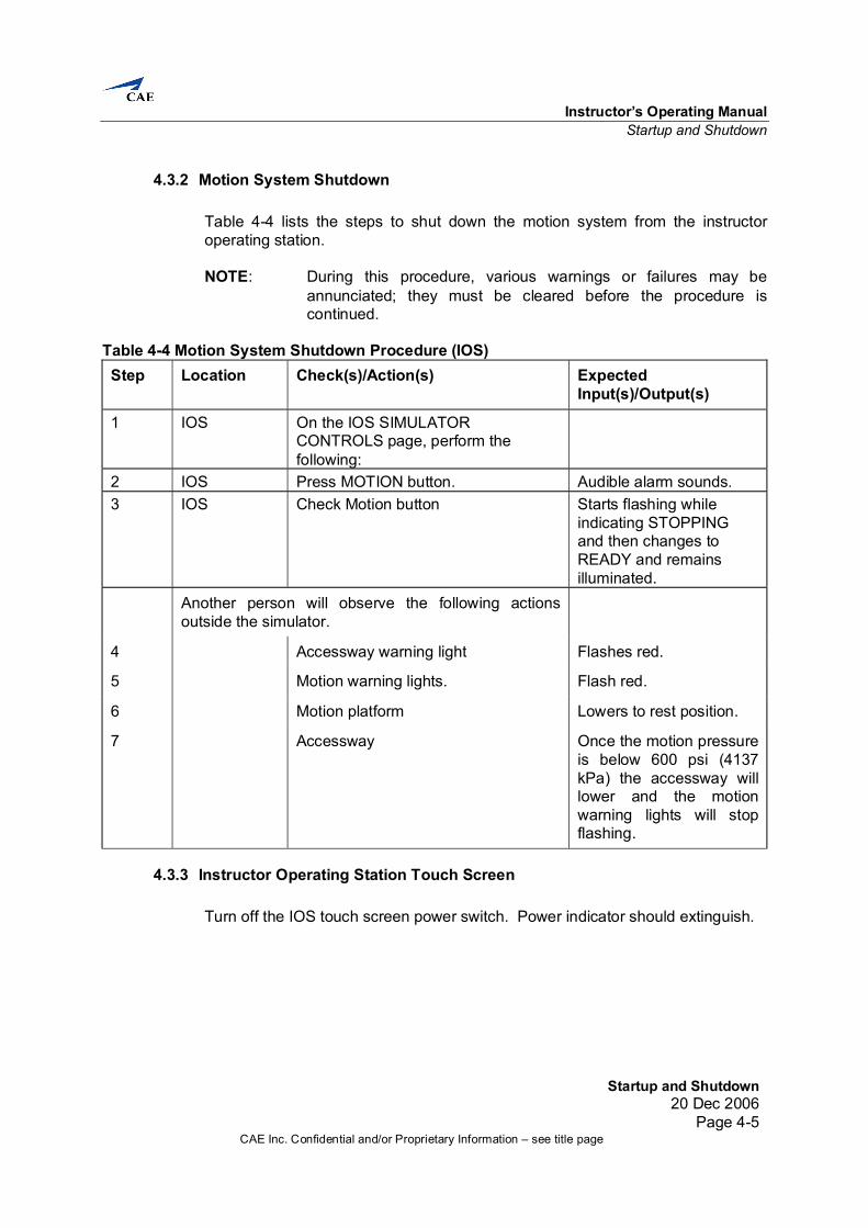
4.3.2 Motion System Shutdown Table 4-4 lists the steps to shut down the motion system from the instructor operating station. NOTE: During this procedure, various warnings or failures may be
annunciated; they must be cleared before the procedure is continued.
indicating STOPPING and then changes to READY and remains illuminated.
Another person will observe the following actions outside the simulator.
4 Accessway warning light Flashes red.
5 Motion warning lights. Flash red.
6 Motion platform Lowers to rest position.
7 Accessway Once the motion pressure is below 600 psi (4137 kPa) the accessway will lower and the motion warning lights will stop flashing.
4.3.3 Instructor Operating Station Touch Screen Turn off the IOS touch screen power switch. Power indicator should extinguish.
Instructor’s Operating Manual Flight Readiness
Flight Readiness20 Dec 2006
Page 5-1CAE Inc. Confidential and/or Proprietary Information – see title page
Flight Readiness 5. Introduction
Before starting a training session, ensure that the instructor station is in a preflight condition, i.e., ready to be activated. Scan the station and refer to the following paragraphs to determine its readiness.
5.1 Preflight Checks
5.1.1 Panel 1: Emergency Shutdown No preflight check is necessary.
5.1.2 Panel 2: Communications Facility Set up the panel as required for the training session.
5.1.3 Panel 3: Lighting Control Adjust the two control knobs to the desired lighting intensity and push the CEILING LIGHTS button to turn the ceiling lights on.
5.1.4 Panel 4: Accessway Control No preflight check is necessary.
5.1.5 Panel 5: Temperature Control Ensure that the desired temperature is displayed. If not, set accordingly (refer to Section 6 for instructions on how to set the controls).
5.2 Postflight Checks At the end of a training session, it is desirable to return the simulator to normal conditions. To achieve this, perform the following functions:
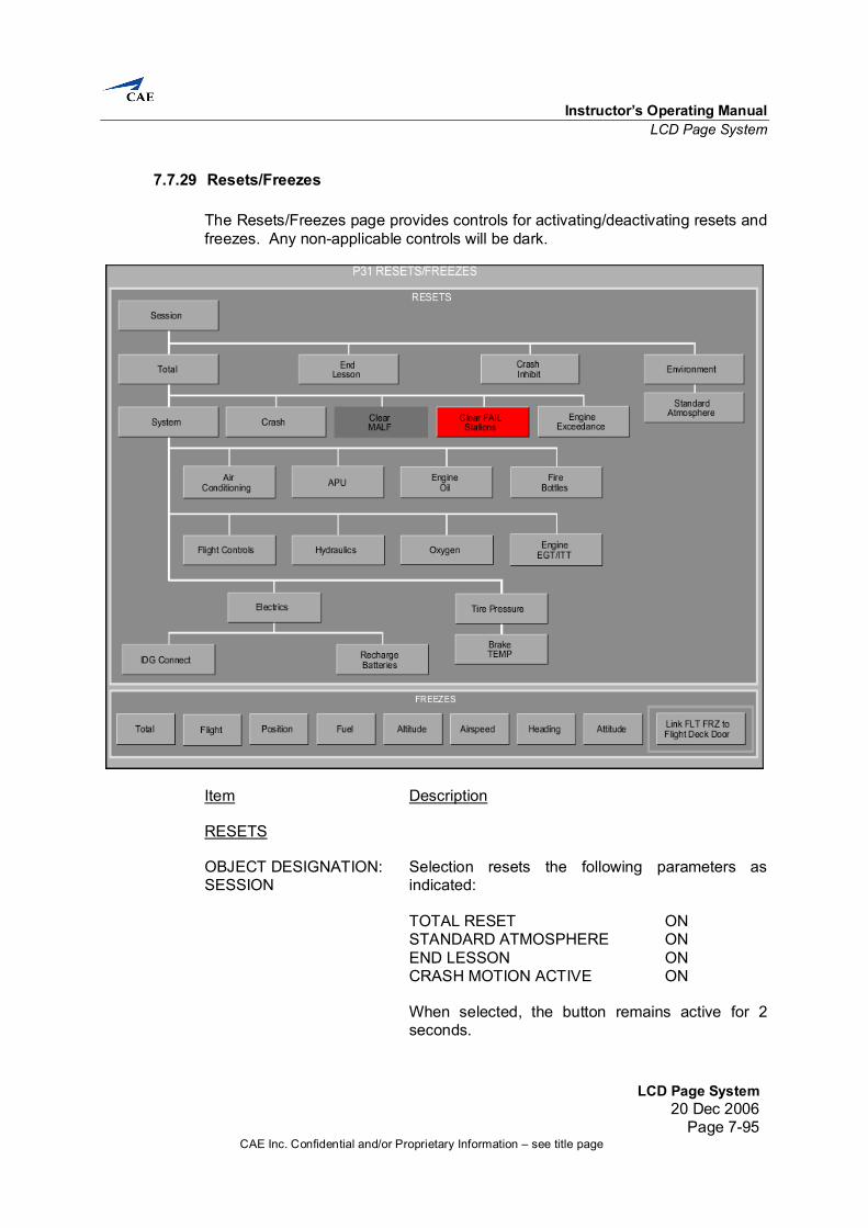
5.2.1 Reset To return the simulator to normal conditions select TOTAL RESET from the Resets/Freezes page.
5.2.2 Motion and Control Loading Refer to Section 4 for a description of the Motion and Control Loading shutdown procedures.
Instructor’s Operating Manual Instructor Station Panel Description
Instructor Station Panel Description20 Dec 2006
Page 6-1CAE Inc. Confidential and/or Proprietary Information – see title page
Instructor Station Panel Description 6. Introduction
This section provides a description of the individual panels located on the instructor station.
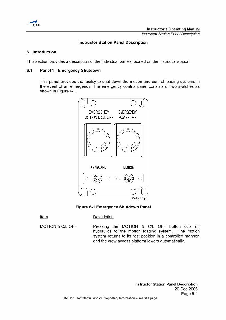
6.1 Panel 1: Emergency Shutdown This panel provides the facility to shut down the motion and control loading systems in the event of an emergency. The emergency control panel consists of two switches as shown in Figure 6-1.
Figure 6-1 Emergency Shutdown Panel
Item Description MOTION & C/L OFF Pressing the MOTION & C/L OFF button cuts off
hydraulics to the motion loading system. The motion system returns to its rest position in a controlled manner, and the crew access platform lowers automatically.
Full Flight Simulator Instructor’s Operating Manual
Instructor Station Panel Description 20 Dec 2006 Page 6-2
CAE Inc. Confidential and/or Proprietary Information – see title page
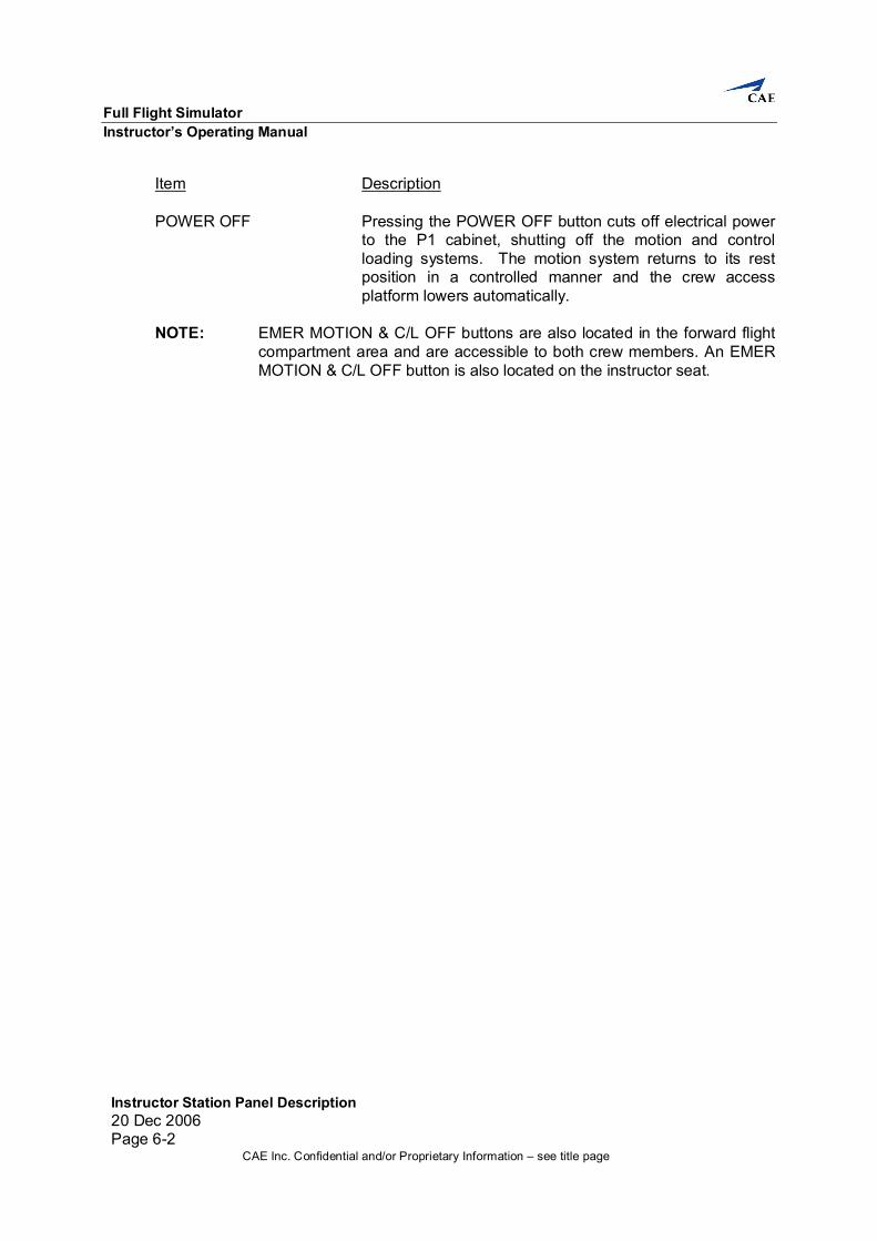
Item Description POWER OFF Pressing the POWER OFF button cuts off electrical power
to the P1 cabinet, shutting off the motion and control loading systems. The motion system returns to its rest position in a controlled manner and the crew access platform lowers automatically.
NOTE: EMER MOTION & C/L OFF buttons are also located in the forward flight
compartment area and are accessible to both crew members. An EMER MOTION & C/L OFF button is also located on the instructor seat.
Instructor’s Operating Manual Instructor Station Panel Description
Instructor Station Panel Description20 Dec 2006
Page 6-3CAE Inc. Confidential and/or Proprietary Information – see title page
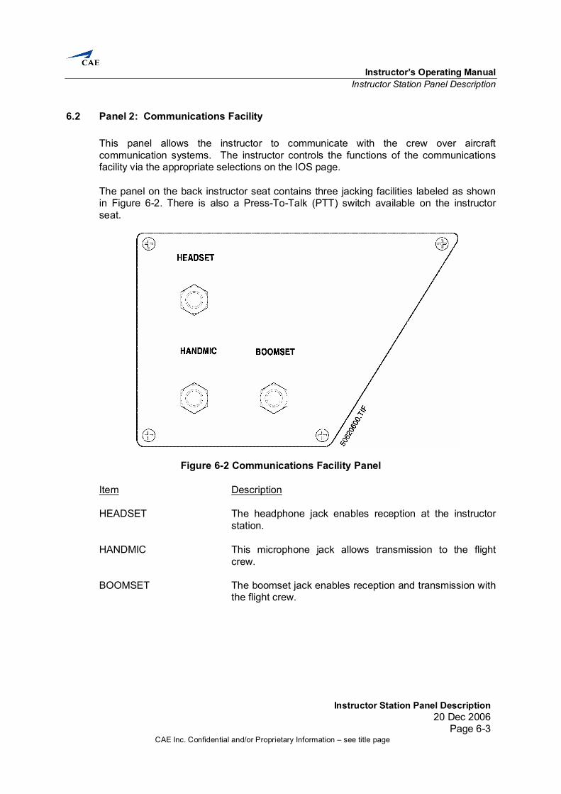
6.2 Panel 2: Communications Facility This panel allows the instructor to communicate with the crew over aircraft communication systems. The instructor controls the functions of the communications facility via the appropriate selections on the IOS page. The panel on the back instructor seat contains three jacking facilities labeled as shown in Figure 6-2. There is also a Press-To-Talk (PTT) switch available on the instructor seat.
Figure 6-2 Communications Facility Panel Item Description HEADSET The headphone jack enables reception at the instructor
station. HANDMIC This microphone jack allows transmission to the flight
crew. BOOMSET The boomset jack enables reception and transmission with
the flight crew.
Full Flight Simulator Instructor’s Operating Manual
Instructor Station Panel Description 20 Dec 2006 Page 6-4
CAE Inc. Confidential and/or Proprietary Information – see title page
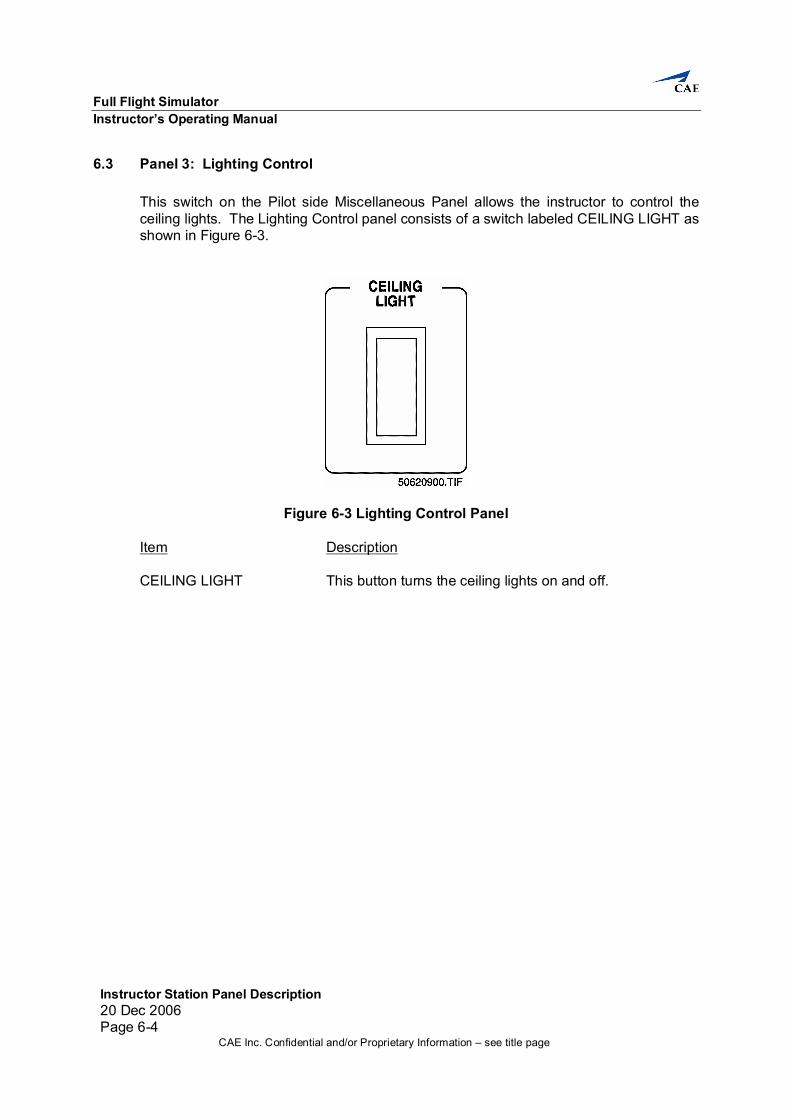
6.3 Panel 3: Lighting Control This switch on the Pilot side Miscellaneous Panel allows the instructor to control the ceiling lights. The Lighting Control panel consists of a switch labeled CEILING LIGHT as shown in Figure 6-3.
Figure 6-3 Lighting Control Panel
Item Description CEILING LIGHT This button turns the ceiling lights on and off.
Instructor’s Operating Manual Instructor Station Panel Description
Instructor Station Panel Description20 Dec 2006
Page 6-5CAE Inc. Confidential and/or Proprietary Information – see title page
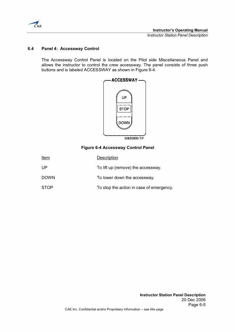
6.4 Panel 4: Accessway Control The Accessway Control Panel is located on the Pilot side Miscellaneous Panel and allows the instructor to control the crew accessway. The panel consists of three push buttons and is labeled ACCESSWAY as shown in Figure 6-4.
Figure 6-4 Accessway Control Panel
Item Description UP To lift up (remove) the accessway. DOWN To lower down the accessway. STOP To stop the action in case of emergency.
Full Flight Simulator Instructor’s Operating Manual
Instructor Station Panel Description 20 Dec 2006 Page 6-6
CAE Inc. Confidential and/or Proprietary Information – see title page
6.5 Panel 5: Temperature Control This panel allows the instructor to display the present temperature, the set temperature or an alarm value, and to set a temperature or an alarm value. The panel contains an LED display and three control keys as shown in Figure 6-5. A hidden key provides for protection from unauthorized users.
Figure 6-5 Temperature Control Panel Item Description LED Display The LED display displays the present temperature, set
temperature or alarm value (usually not used) depending on the main display value chosen using the return key. The up and down deviation indicators to the left of the main display illuminate if the present temperature is higher or lower than the set temperature. The square indicator appears in green if the deviation is within 1% of the full scale.
SP SP appears beside the main display when set temperature
is displayed. ON The control output indicator illuminates while the control
output is being produced. Return Key The return key changes the value displayed on the main
display from present temperature to set temperature to alarm value.
Instructor’s Operating Manual LCD Page System
LCD Page System20 Dec 2006
Page 7-1CAE Inc. Confidential and/or Proprietary Information – see title page
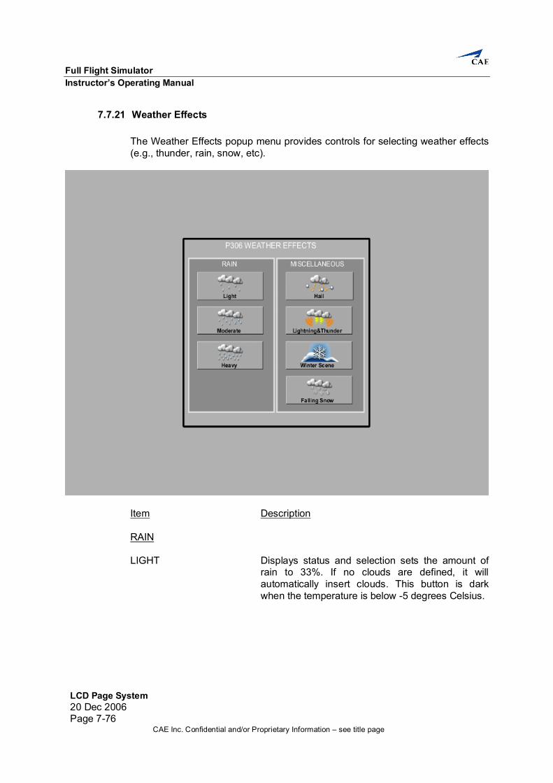
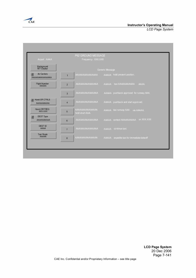
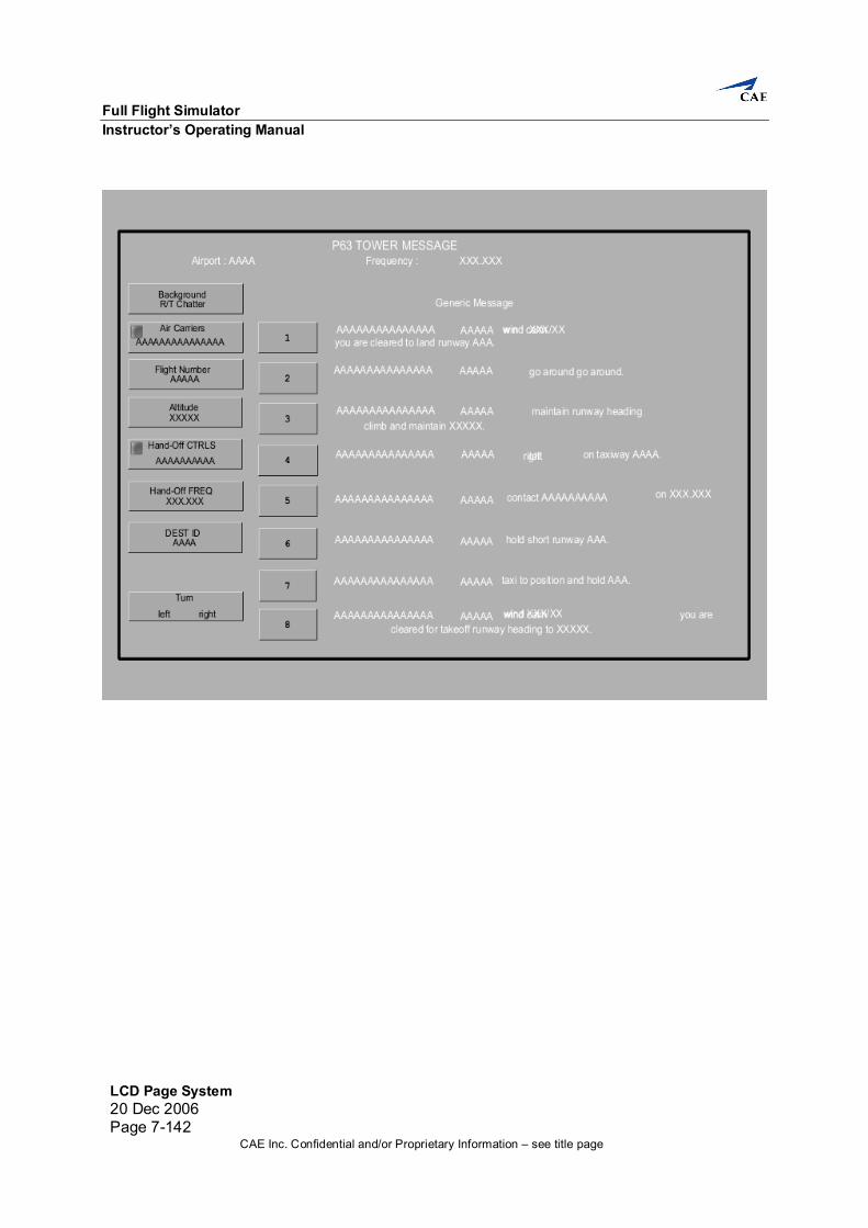
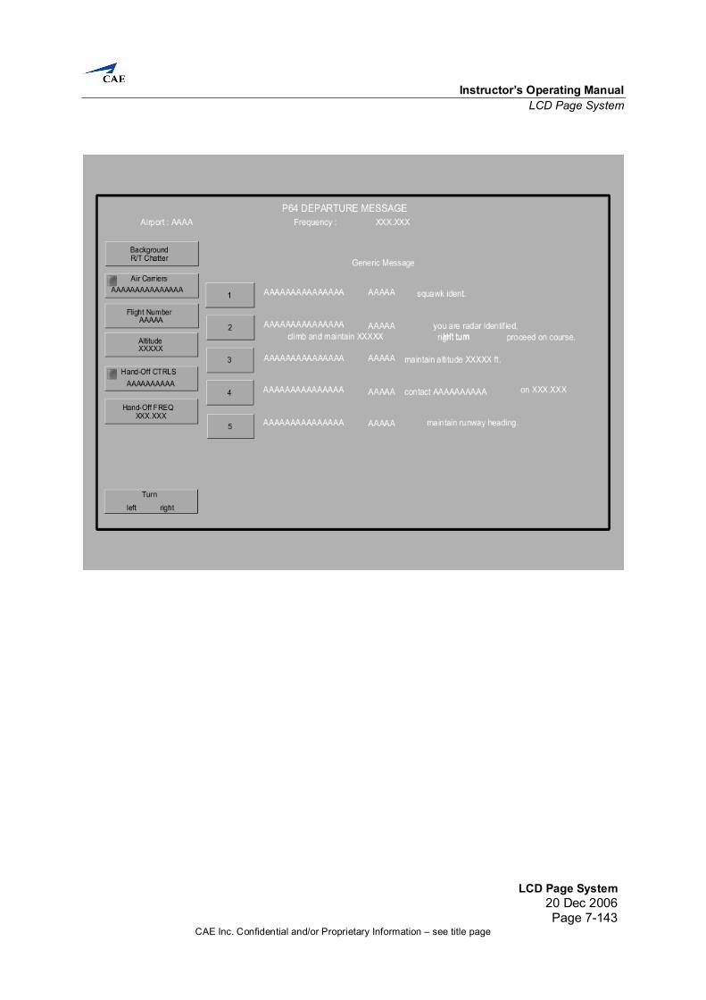
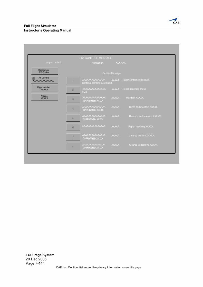
LCD Page System 7. Introduction
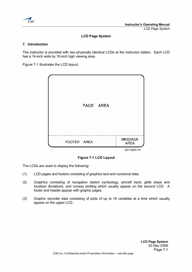
The instructor is provided with two physically identical LCDs at the instructor station. Each LCD has a 14-inch wide by 10-inch high viewing area. Figure 7-1 illustrates the LCD layout.
Figure 7-1 LCD Layout The LCDs are used to display the following: (1) LCD pages and footers consisting of graphics text and numerical data. (2) Graphics consisting of navigation station symbology, aircraft track, glide slope and
localizer deviations, and runway plotting which usually appear on the second LCD. A footer and header appear with graphic pages.
(3) Graphic recorder data consisting of plots of up to 16 variables at a time which usually
appear on the upper LCD.
Full Flight Simulator Instructor’s Operating Manual
LCD Page System 20 Dec 2006 Page 7-2
CAE Inc. Confidential and/or Proprietary Information – see title page
LCD pages are lists of information grouped logically by function or system, each uniquely identified by a number in the range of 1 to 2500. Each LCD page is a collection of items. Typically, an item is composed of a comment field and a volatile field. The comment field describes the parameter or function and does not change (although it may change color), and the volatile field displays the parameter value or state and follows changes in the value or state. In addition to displaying information, the instructor can change information on an LCD page. Items whose state or value the instructor can change have a box or touch area around them. Items are selected by touching the area within the box. LCD pages can be selected from: (1) Index pages (2) Menu from the footer area (3) Lesson plans.
7.1 LCD Page Input/Output Types Variables on an LCD page are displayed using different formats depending on the type of the variable. The types of variables that may be found on an LCD page are described as follows: (1) DECIMAL: A decimal type function displays and accepts input in a decimal
format. This includes the latitude/longitude, angle, time, and alphanumeric formats.
(2) BOOLEAN. A Boolean type function has two states: on and off. (3) SET VALUE: A set value type function sets a predetermined value for up to 60
decimal or Boolean type variables when selected. A set value may also be pre-programmed to activate when certain criteria are met.
(4) MULTIPLE: A multiple type function is a single display, which may display up to
10 decimal functions. (5) BAR CHART/BAR SCROLL: Decimal values also may be displayed and accept
input in the form of a bar chart/bar scroll graphic representation. (6) POPUP MENU: A popup menu function displays a window that contains
additional controls relating to the selection made.
Instructor’s Operating Manual LCD Page System
LCD Page System20 Dec 2006
Page 7-3CAE Inc. Confidential and/or Proprietary Information – see title page
7.2 LCD Pages Color Logic The LCD pages can use the following eight colors: red, green, blue, cyan, magenta, white, yellow and black. The LCD page color logic is described in the following paragraphs.
7.2.1 Regular and Lesson Page Color Logic The color logic for regular text pages and scenario pages is as follows: (1) GREEN: The fill color of boxes around discrete functions which are
active (on), and the lesson plan text for steps already actioned is green. (2) RED: The fill color of boxes around freeze functions which are active (on)
is red. (3) LIGHT GRAY: The fill color of boxes around freeze functions which are
inactive (off) is light gray. (4) BLACK: This is the normal color for text displayed within the touch
boxes. (5) WHITE: This is the normal color for text displayed on the LCD page and
in the header and footer areas. The lesson plan text for steps yet to be actioned is white.
(6) YELLOW: The lesson step of interest in an active lesson plan is yellow.
The fill color of a decimal item on input is yellow. (7) CYAN: The fill color of an item on input (when touched) is cyan.
7.2.2 Malfunction Pages Color Logic The color logic for malfunction pages is as follows: (1) RED: The fill color of the box around an active malfunction is red. (2) LIGHT GRAY: The fill color of the box around an inactive malfunction is
light gray. (3) WHITE: Text on malfunction pages is white. (4) MAGENTA: Preselected malfunction information text is magenta.
Full Flight Simulator Instructor’s Operating Manual
LCD Page System 20 Dec 2006 Page 7-4
CAE Inc. Confidential and/or Proprietary Information – see title page
7.2.3 Map Color Logic The color logic for map pages is as follows: (1) GREEN: The default color for all information and the spiderweb is green. (2) RED: Killed stations (including idents) are red. (3) YELLOW: Tuned stations (including idents) are yellow. NOTE: Killed status overrides tuned status for display purposes. (4) WHITE: The aircraft symbol and aircraft track and trail, including the
spiderweb, are white. Radio station idents have the same color as the station symbol. Station frequency displays are white.
7.2.4 Approach Plots Color Logic The approach plot color logic is as follows: (1) GREEN: The default color for all information and the plot grids are green. (2) WHITE: The localizer deviation, glide slope deviation, target speed, and
the non-precision plots are white. (3) RED: The localizer deviation plot is red when ±2 dots deviation is
exceeded or the grid limits are reached. The glide slope deviation plot is red when ±1 dot deviation is exceeded or the limits are reached. The speed deviation plot is red when the grid limits are reached. The touchdown marker and the runway length vector are also red.
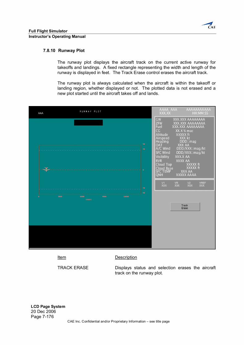
7.2.5 Runway Plots Color Logic The runway plot color logic is as follows: (1) GREEN: The default color for all information is green. The plot grids are
green. (2) WHITE: The aircraft symbol is white. The aircraft track is white when the
aircraft is on the ground, (3) CYAN: The aircraft track is cyan when the aircraft is in the air.
Instructor’s Operating Manual LCD Page System
LCD Page System20 Dec 2006
Page 7-5CAE Inc. Confidential and/or Proprietary Information – see title page
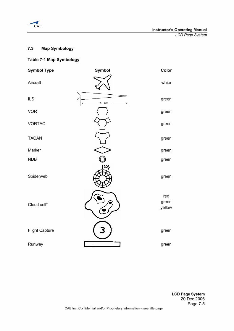
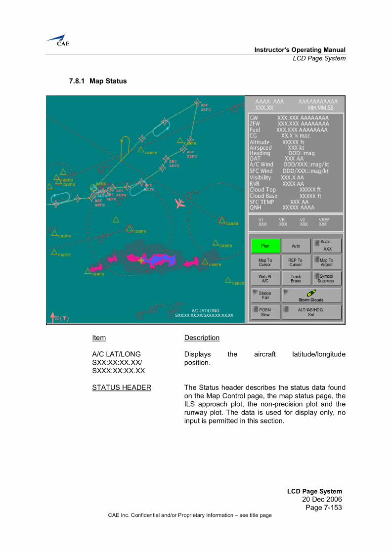
7.3 Map Symbology Table 7-1 Map Symbology Symbol Type Symbol Color
Aircraft
white
ILS
green
VOR
green
VORTAC
green
TACAN
green
Marker
green
NDB green
Spiderweb
green
Cloud cell*
red green yellow
Flight Capture
green
Runway green
Full Flight Simulator Instructor’s Operating Manual
LCD Page System 20 Dec 2006 Page 7-6
CAE Inc. Confidential and/or Proprietary Information – see title page
7.4 LCD Pages LCD pages are divided into the following groups and are described on the following pages: (1) Footer pages (2) Index pages (3) Control pages (4) Map pages (5) Malfunction pages (6) Lesson Plan pages (7) Maintenance pages (8) Help pages. NOTE: All LCD pages included in this IOM are snapshots of LCD pages at Ready
for Training (RFT).
Instructor’s Operating Manual LCD Page System
LCD Page System20 Dec 2006
Page 7-7CAE Inc. Confidential and/or Proprietary Information – see title page
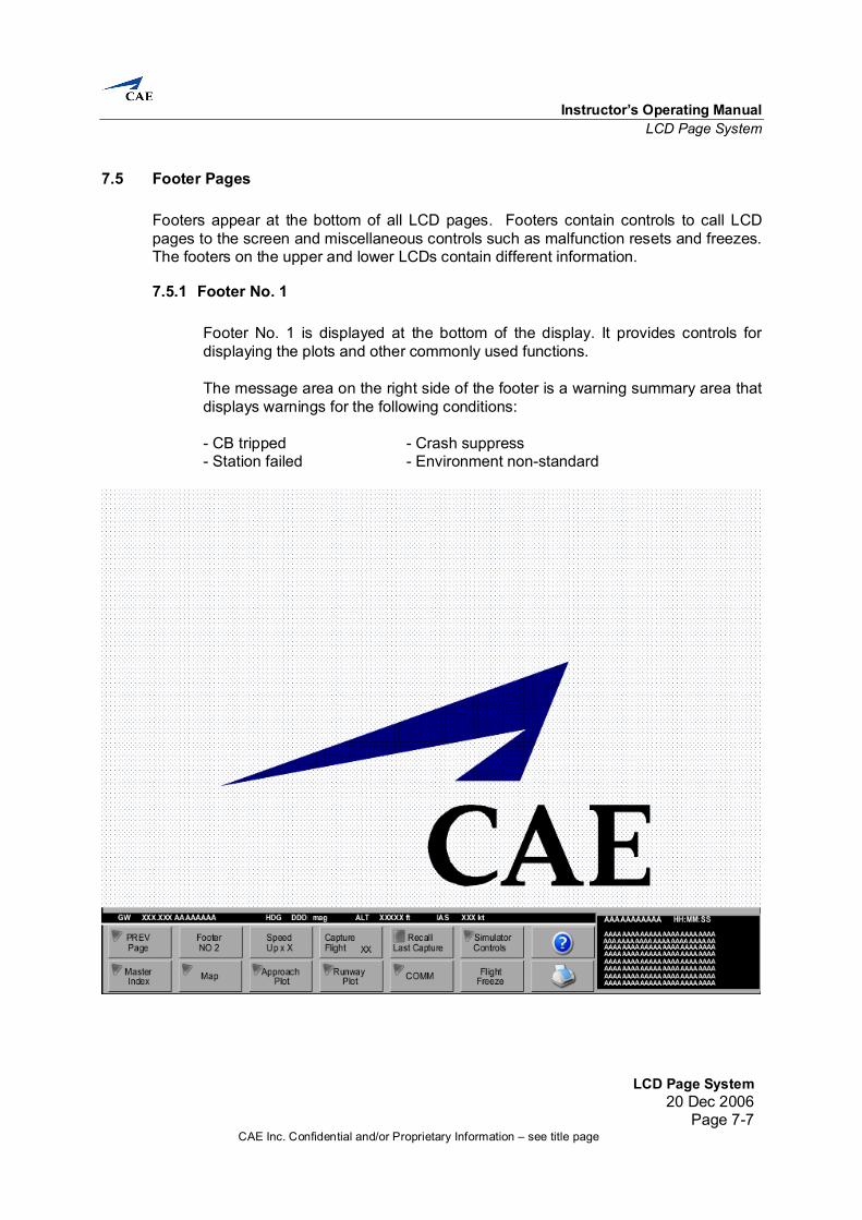
7.5 Footer Pages Footers appear at the bottom of all LCD pages. Footers contain controls to call LCD pages to the screen and miscellaneous controls such as malfunction resets and freezes. The footers on the upper and lower LCDs contain different information.
7.5.1 Footer No. 1 Footer No. 1 is displayed at the bottom of the display. It provides controls for displaying the plots and other commonly used functions. The message area on the right side of the footer is a warning summary area that displays warnings for the following conditions: - CB tripped - Crash suppress - Station failed - Environment non-standard
Full Flight Simulator Instructor’s Operating Manual
LCD Page System 20 Dec 2006 Page 7-8
CAE Inc. Confidential and/or Proprietary Information – see title page
Item Description PREV PAGE Selection displays the previously displayed page.
When selected, the button remains active for two seconds.
FOOTER NO 2 Selection displays the Footer No. 2 page in the
footer area. SPEED UP X X Displays status and selection allows input of the
ground speed, speed up factor. Selection maintains current indicated airspeed but increases ground speed rate by the speed up factor.
Although the speed up factor displayed on the
button does not change, the speed up factor used in the simulation automatically reverts back to one in conditions where LNAV is engaged and the roll or pitch exceed reasonable angles. The purpose is to force back a normal speed to allow the aircraft to follow the flight plan properly in the critical phases of the flight plan. Please note the fuel consumption follows the speed up factor.
(Min = 1, Max = Dynamic) CAPTURE FLIGHT Displays status and selection activates a flight
situation capture operation. When selected, the button remains active for 2 seconds. The button is dark if a recall is active.
RECALL LAST CAPTURE Selection displays the Recall Last Capture confirm
popup menu. SIMULATOR CONTROLS Selection displays the requested page. HELP Displays status and selection activates/deactivates
help mode. Selecting an item on the page while help mode is active displays a popup containing a description of the selected item. If no selection is made within 2-3 seconds after help mode is activated, a popup describing the functionality of the current page appears.
MASTER INDEX Displays status and selection displays the Master
Index page on the display.
Instructor’s Operating Manual LCD Page System
LCD Page System20 Dec 2006
Page 7-9CAE Inc. Confidential and/or Proprietary Information – see title page
Item Description MAP Displays status and selection displays the Map
page on the display. APPROACH PLOT Selection displays the Approach Plot. RUNWAY PLOT Displays status and selection displays the Runway
Plot on the display. COMM Selection displays the requested page. FLIGHT FREEZE Displays status and selection activates/deactivates
flight freeze. When flight freeze is active, the following occurs: (1) All flight parameters (i.e., pitch, bank,
heading, airspeed) freeze. (2) Altitude and position freeze. (3) The motion system freezes except for
washout as predicted by the flight conditions at the moment of freeze.
(4) Sound level decreases. (5) Most simulated aircraft systems remain
unaffected and continue to follow crew actions and malfunction insertions except for the effects of frozen altitude and position parameters. Release of flight freeze does not cause violent control or motion movements, irrespective of whether the autopilot is on or off and independent of the control positions at the moment of unfreeze.
(6) During a reposition, the flight freeze button is dark until the reposition or flight trim is completed.
HARDCOPY Displays status and selection makes a hardcopy of
the page displayed. WARNING DATE Displays the current year, month and day. TIME Displays time in hours, minutes, seconds format. AAAAAAAAAAAA Displays the warnings.
Full Flight Simulator Instructor’s Operating Manual
LCD Page System 20 Dec 2006 Page 7-10
CAE Inc. Confidential and/or Proprietary Information – see title page
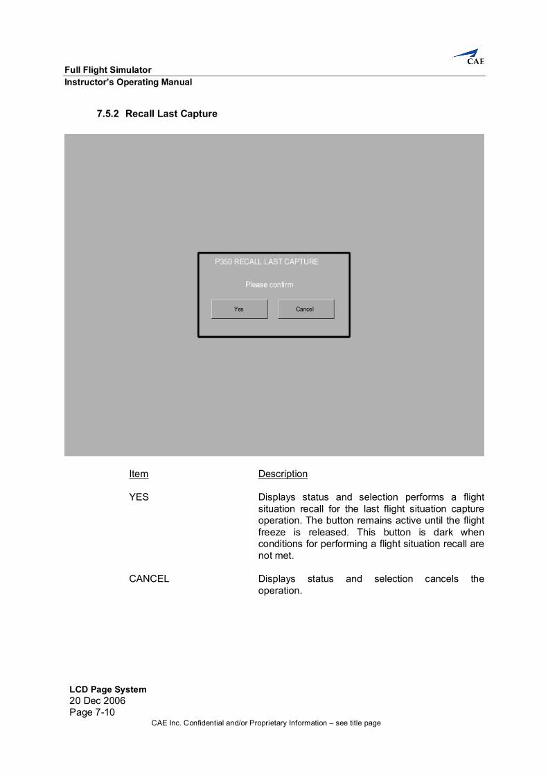
7.5.2 Recall Last Capture
Item Description YES Displays status and selection performs a flight
situation recall for the last flight situation capture operation. The button remains active until the flight freeze is released. This button is dark when conditions for performing a flight situation recall are not met.
CANCEL Displays status and selection cancels the
operation.
Instructor’s Operating Manual LCD Page System
LCD Page System20 Dec 2006
Page 7-11CAE Inc. Confidential and/or Proprietary Information – see title page
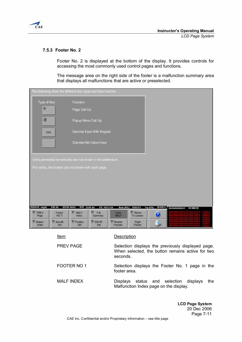
7.5.3 Footer No. 2 Footer No. 2 is displayed at the bottom of the display. It provides controls for accessing the most commonly used control pages and functions. The message area on the right side of the footer is a malfunction summary area that displays all malfunctions that are active or preselected.
Item Description PREV PAGE Selection displays the previously displayed page. When selected, the button remains active for two seconds. FOOTER NO 1 Selection displays the Footer No. 1 page in the footer area. MALF INDEX Displays status and selection displays the Malfunction Index page on the display.
Full Flight Simulator Instructor’s Operating Manual
LCD Page System 20 Dec 2006 Page 7-12
CAE Inc. Confidential and/or Proprietary Information – see title page
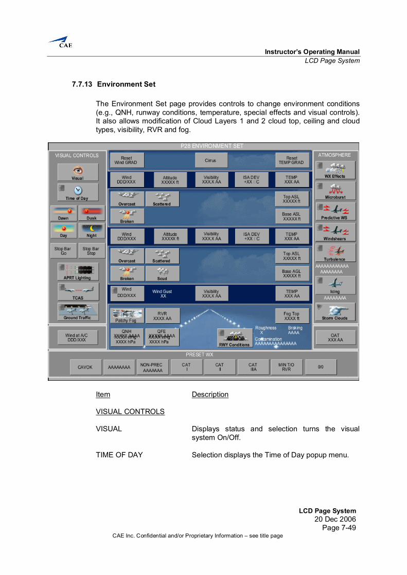
Item Description FAIL SUMMARY Displays status and selection displays the Fail Summary page, which lists all active/preselected malfunctions, popped CBs, and failed stations. CLEAR MALF Displays status and selection clears all active and preselected malfunctions. This button is dark if no malfunctions are active or preselected. When selected, the button remains active for 2 seconds. RETURN TO LESSON Selection displays the active lesson plan. This button is dark if there is no lesson plan active or a lesson is active and is currently being displayed. HELP Displays status and selection activates/deactivates help mode. Selecting an item on the page while help mode is active displays a popup containing a description of the selected item. If no selection is made within 2-3 seconds after help mode is activated, a popup describing the functionality of the current page appears. MASTER INDEX Displays status and selection displays the Master Index page on the display. AIRCRAFT SET Displays status and selection displays the A/C Set page, which displays and allows input of aircraft parameters (e.g. GW, CG, fuel tanks). POSITION SET Displays status and selection displays the Position Set page, which allows the instructor to reposition the aircraft, specify the reference runway, and initiate pushback. ENVIR SET Displays status and selection displays the Environment Set page, which allows input of environment conditions (e.g., QNH, temp, runway conditions, special effects, and visual conditions). RESETS/ FREEZES Displays status and selection displays the Freeze/Reset page, which lists the freezes and resets available.
Instructor’s Operating Manual LCD Page System
LCD Page System20 Dec 2006
Page 7-13CAE Inc. Confidential and/or Proprietary Information – see title page
Item Description FLIGHT FREEZE Displays status and selection activates/deactivates flight freeze. When flight freeze is active, the following occurs: (1) All flight parameters (i.e., pitch, bank,
heading, airspeed) freeze. (2) Altitude and position freeze. (3) The motion system freezes except for
washout as predicted by the flight conditions at the moment of freeze.
(4) Sound level decreases. Most simulated aircraft systems remain unaffected and continue to follow crew actions and malfunction insertions except for the effects of frozen altitude and position parameters. Release of flight freeze does not cause violent control or motion movements, irrespective of whether the autopilot is on or off and independent of the control positions at the moment of unfreeze. During a reposition, the flight freeze button is dark until the reposition or flight trim is completed.
HARDCOPY Displays status and selection makes a hardcopy of the page displayed. MALFUNCTION DATE Displays the current year, month and day. TIME Displays time in hours, minutes, seconds format. DESCRIPTION Displays the description of the selected malfunction. SYSTEM DESCRIPTION Displays the system name of the selected
malfunction.
Full Flight Simulator Instructor’s Operating Manual
LCD Page System 20 Dec 2006 Page 7-14
CAE Inc. Confidential and/or Proprietary Information – see title page
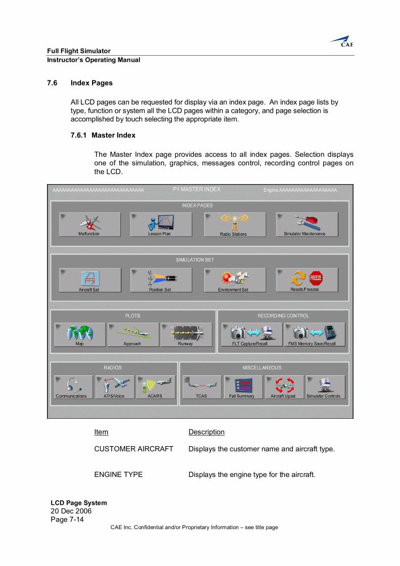
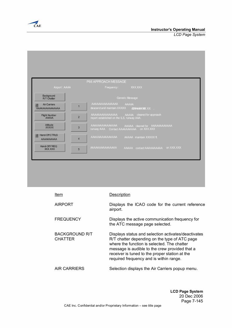
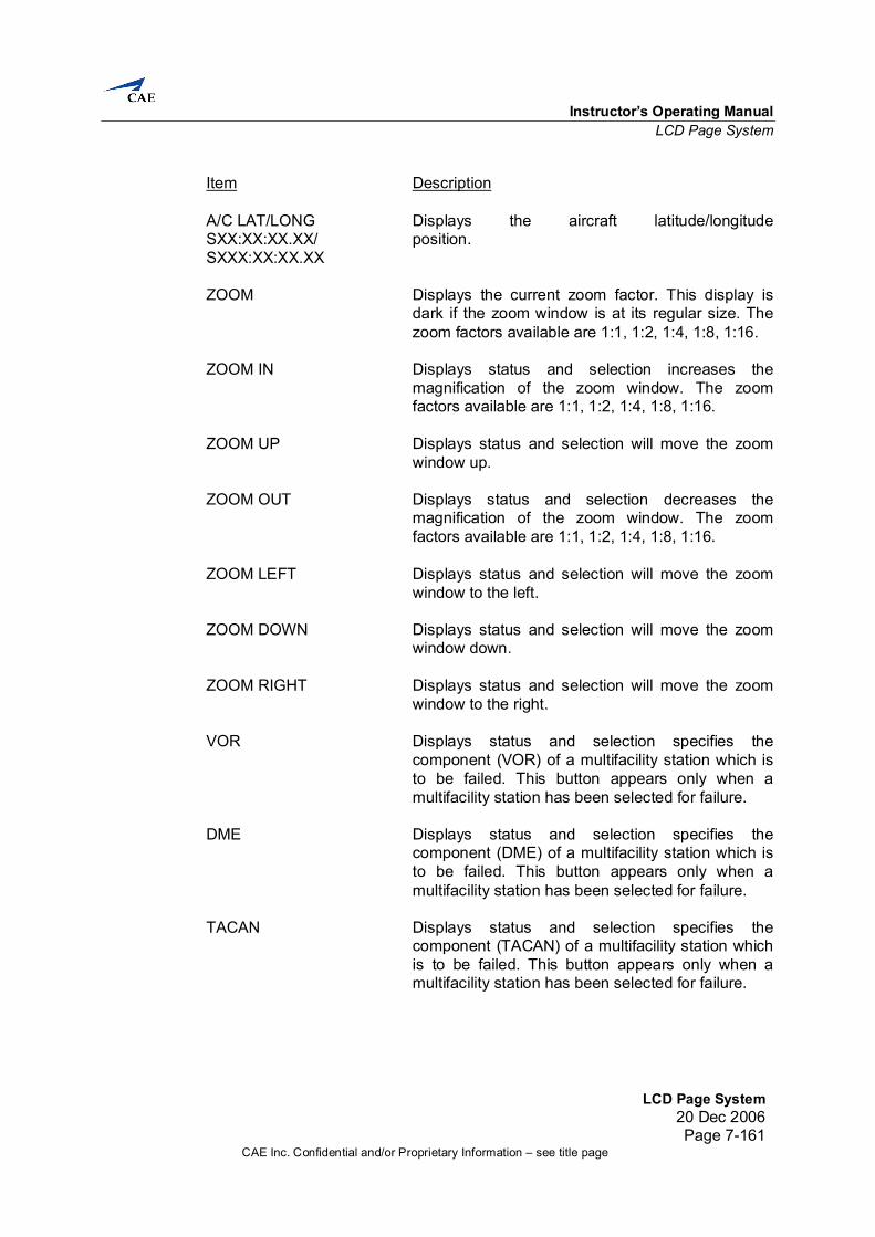
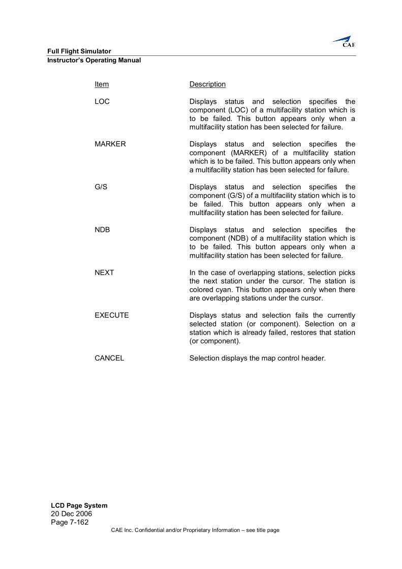
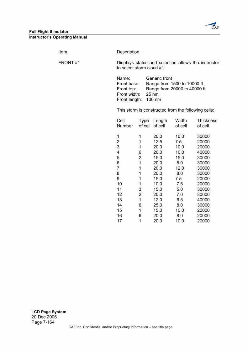
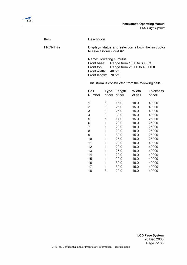
7.6 Index Pages All LCD pages can be requested for display via an index page. An index page lists by type, function or system all the LCD pages within a category, and page selection is accomplished by touch selecting the appropriate item.
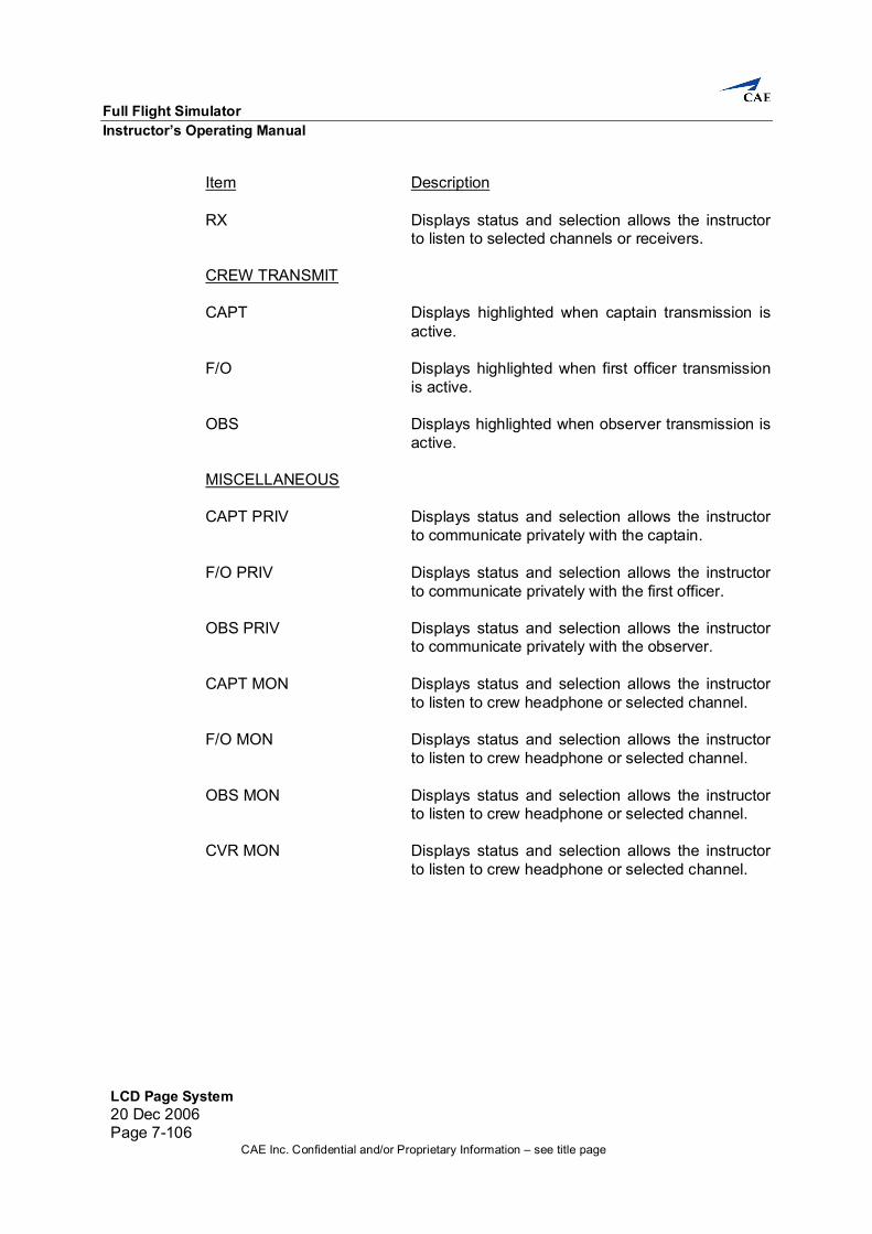
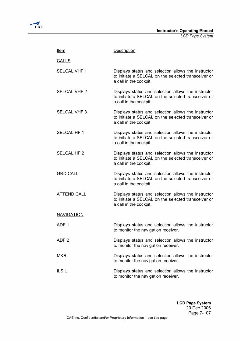
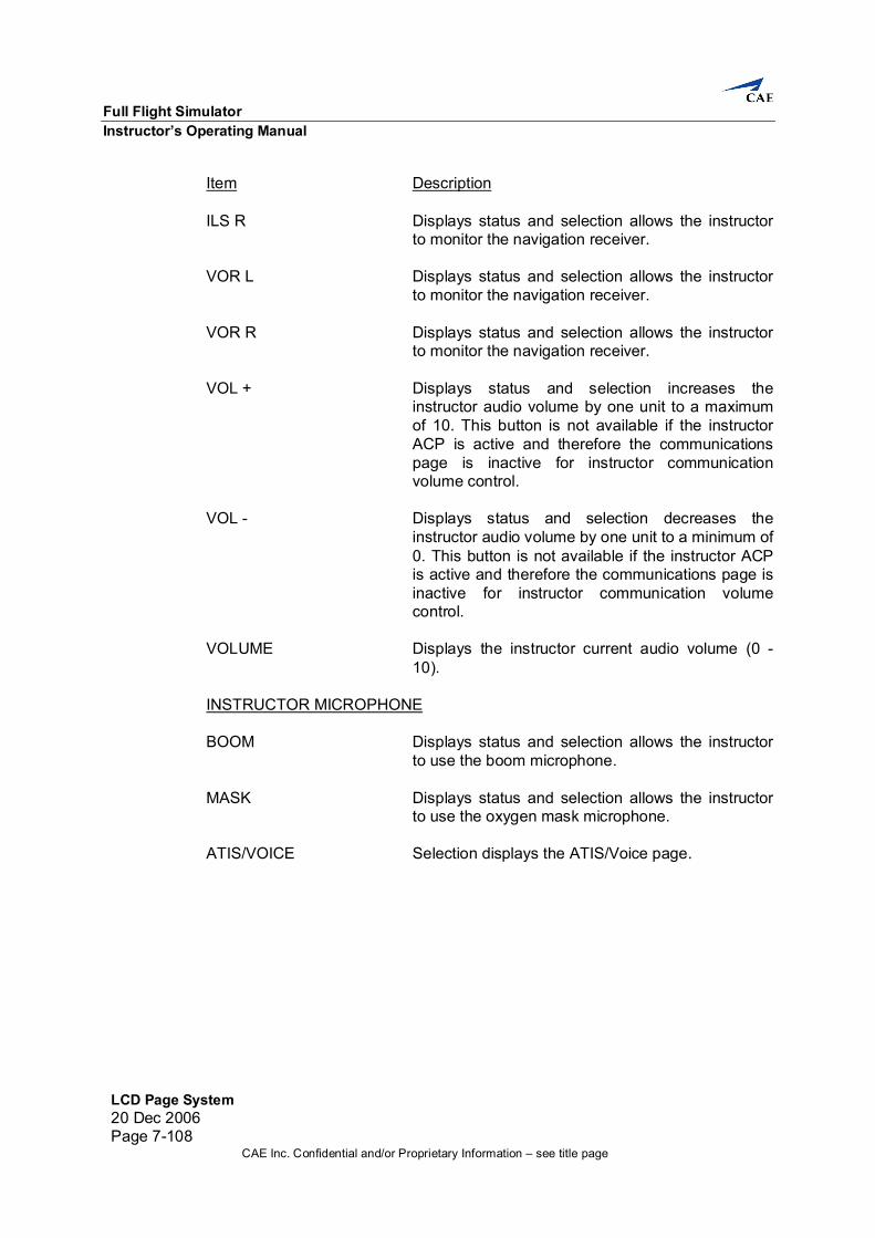
7.6.1 Master Index The Master Index page provides access to all index pages. Selection displays one of the simulation, graphics, messages control, recording control pages on the LCD.
Item Description CUSTOMER AIRCRAFT Displays the customer name and aircraft type. ENGINE TYPE Displays the engine type for the aircraft.
Instructor’s Operating Manual LCD Page System
LCD Page System20 Dec 2006
Page 7-15CAE Inc. Confidential and/or Proprietary Information – see title page
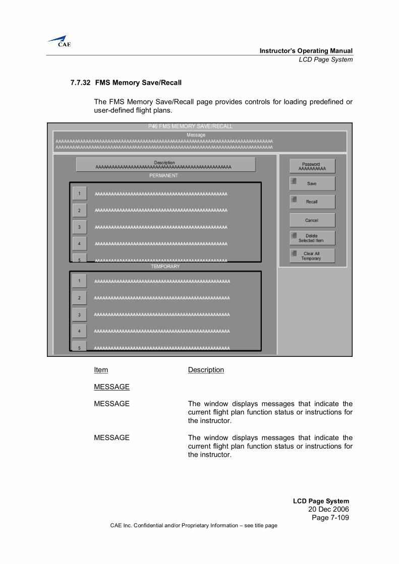
Item Description INDEX PAGES MALFUNCTION Selection displays the requested page. LESSON PLAN Selection displays the requested page. RADIO STATIONS Selection displays the requested page. SIMULATOR Selection displays the requested page. MAINTENANCE SIMULATION SET AIRCRAFT SET Selection displays the requested page. POSITION SET Selection displays the requested page. ENVIRONMENT SET Selection displays the requested page. RESETS/FREEZES Selection displays the requested page. PLOTS MAP Selection displays the requested page. APPROACH Selection displays the requested page. RUNWAY Selection displays the requested page. RECORDING CONTROL FLT CAPTURE/RECALL Selection displays the requested page. FMS MEMORY SAVE/ Selection displays the FMS Memory Save/ RECALL Recall page. RADIOS COMMUNICATIONS Selection displays the requested page. ATIS/VOICE Selection displays the requested page. ACARS Selection displays the requested page.
Full Flight Simulator Instructor’s Operating Manual
LCD Page System 20 Dec 2006 Page 7-16
CAE Inc. Confidential and/or Proprietary Information – see title page
Item Description MISCELLANEOUS TCAS Selection displays the requested popup menu. FAIL SUMMARY Selection displays the requested page. AIRCRAFT UPSET Selection displays the requested page. SIMULATOR CONTROLS Selection displays the requested page.
Instructor’s Operating Manual LCD Page System
LCD Page System20 Dec 2006
Page 7-17CAE Inc. Confidential and/or Proprietary Information – see title page
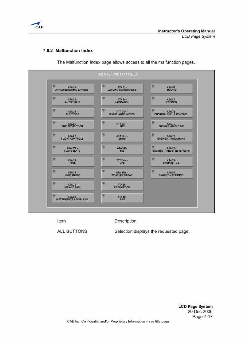
7.6.2 Malfunction Index The Malfunction Index page allows access to all the malfunction pages.
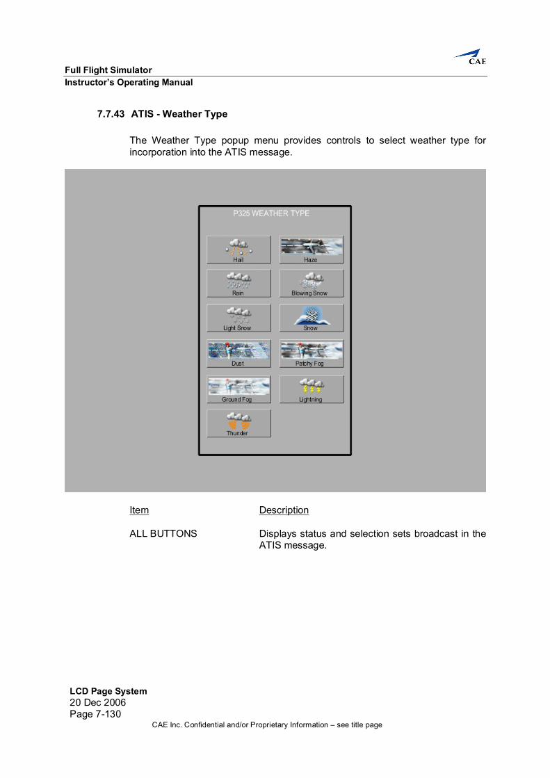
Item Description ALL BUTTONS Selection displays the requested page.
Full Flight Simulator Instructor’s Operating Manual
LCD Page System 20 Dec 2006 Page 7-18
CAE Inc. Confidential and/or Proprietary Information – see title page
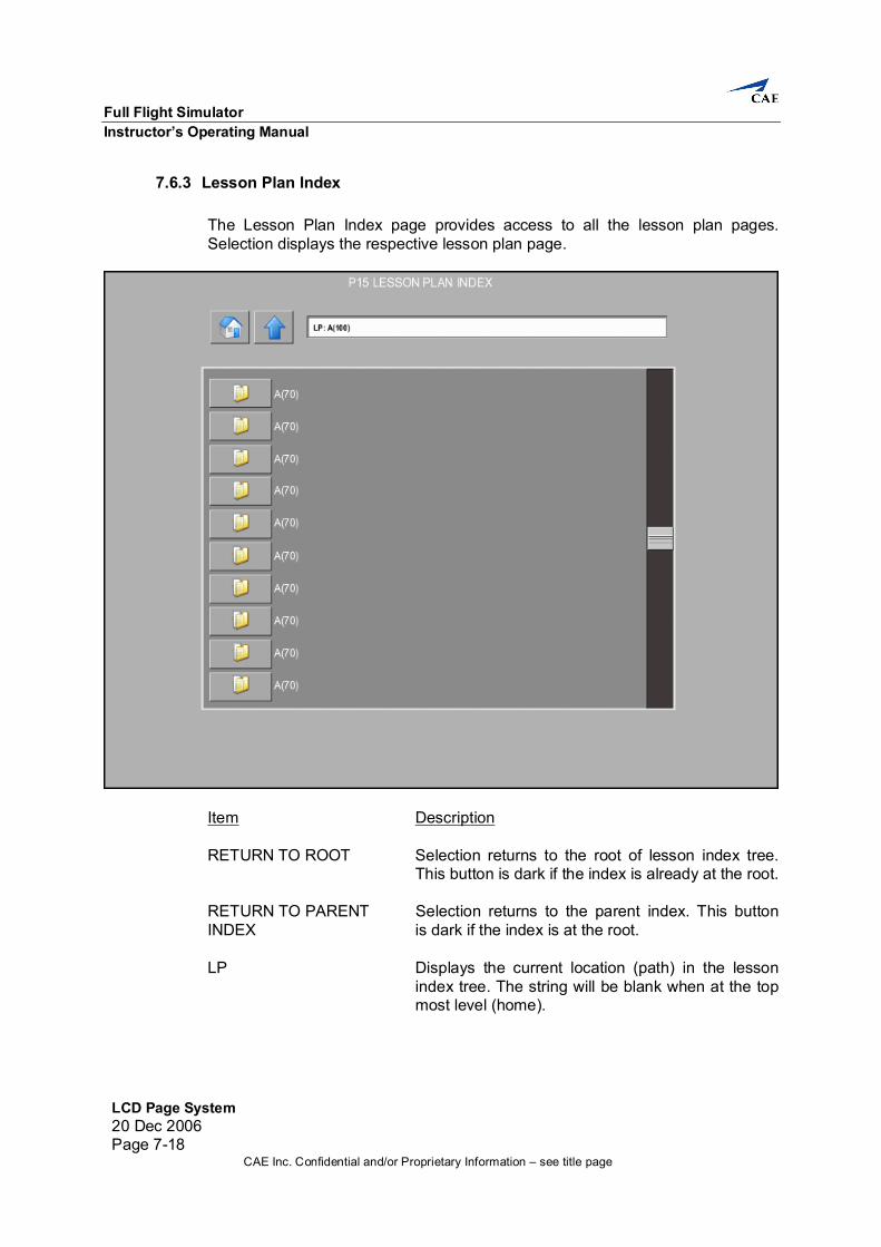
7.6.3 Lesson Plan Index The Lesson Plan Index page provides access to all the lesson plan pages. Selection displays the respective lesson plan page.
Item Description RETURN TO ROOT Selection returns to the root of lesson index tree. This button is dark if the index is already at the root. RETURN TO PARENT Selection returns to the parent index. This button INDEX is dark if the index is at the root. LP Displays the current location (path) in the lesson index tree. The string will be blank when at the top most level (home).
Instructor’s Operating Manual LCD Page System
LCD Page System20 Dec 2006
Page 7-19CAE Inc. Confidential and/or Proprietary Information – see title page
Item Description INDEX SCROLL BAR Displays status and selection allows the instructor to scroll through the lesson/session index listing. LESSON/INDEX CALL Selection displays the corresponding Lesson Index or Lesson Plan.
Full Flight Simulator Instructor’s Operating Manual
LCD Page System 20 Dec 2006 Page 7-20
CAE Inc. Confidential and/or Proprietary Information – see title page
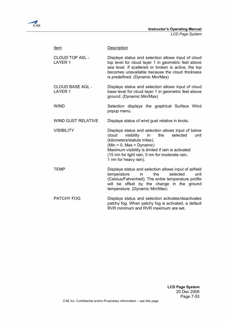
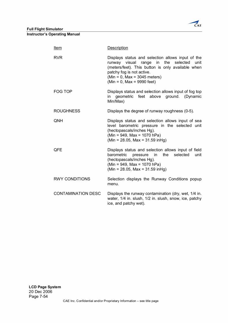
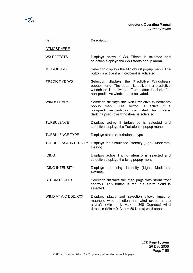
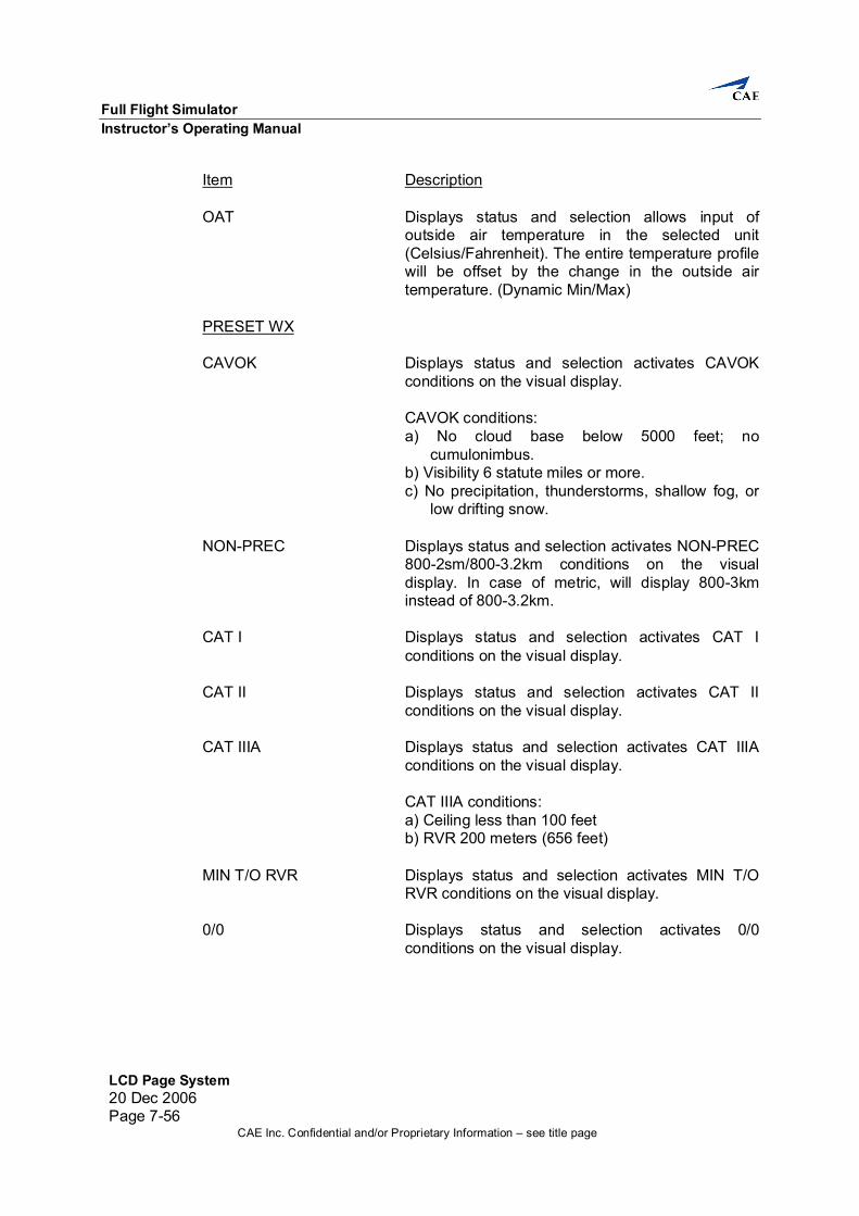
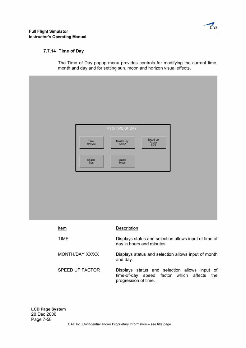
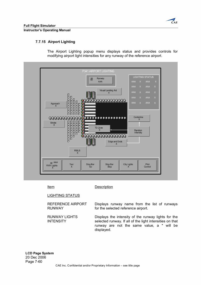
7.7 Control Pages These LCD pages allow the operator to control and monitor the simulated aircraft configuration and environment.
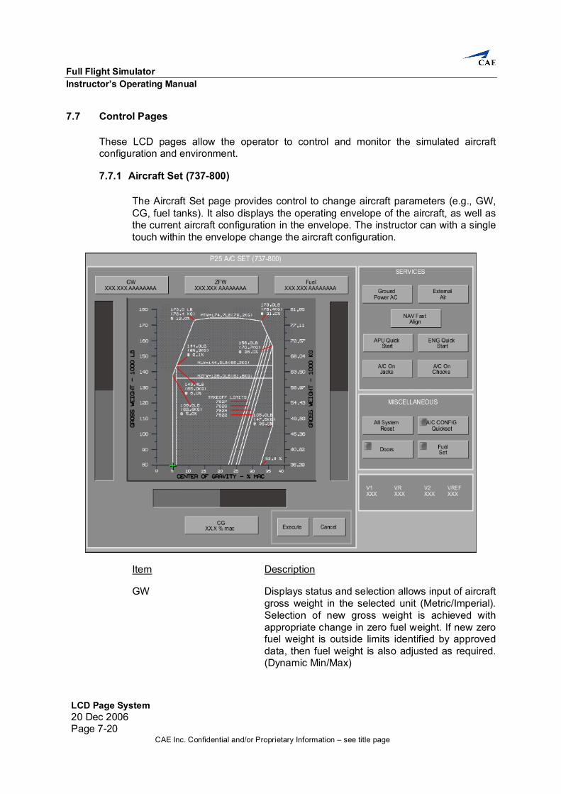
7.7.1 Aircraft Set (737-800) The Aircraft Set page provides control to change aircraft parameters (e.g., GW, CG, fuel tanks). It also displays the operating envelope of the aircraft, as well as the current aircraft configuration in the envelope. The instructor can with a single touch within the envelope change the aircraft configuration.
Item Description GW Displays status and selection allows input of aircraft gross weight in the selected unit (Metric/Imperial). Selection of new gross weight is achieved with appropriate change in zero fuel weight. If new zero fuel weight is outside limits identified by approved data, then fuel weight is also adjusted as required. (Dynamic Min/Max)
Instructor’s Operating Manual LCD Page System
LCD Page System20 Dec 2006
Page 7-21CAE Inc. Confidential and/or Proprietary Information – see title page
Item Description ZFW Displays status and selection allows input of aircraft zero fuel weight in the selected unit (Metric/Imperial). Selection of new zero fuel weight is achieved with appropriate change in gross weight. If new gross weight is outside limits identified by approved data, then fuel weight is also adjusted as required. (Dynamic Min/Max) FUEL Displays status and selection allows input of aircraft total fuel in the selected unit (Metric/Imperial). Fuel is distributed in accordance with the aircraft fuel distribution schedule. Selection of new fuel weight is achieved with appropriate change in gross weight. If new gross weight is outside limits identified by approved data, then zero fuel weight is also adjusted as required. (Dynamic Min/Max) CG Displays status and selection allows input of center
of gravity in % MAC. Selection of new aircraft center of gravity is achieved with appropriate change in zero fuel weight center of gravity. If new zero fuel weight center of gravity is outside limits identified by approved data, then the fuel weight is reduced and the zero fuel weight is increased as required. (Dynamic Min/Max)
EXECUTE Displays status and selection executes the selected
aircraft configuration change ( Gw, ZFW, or CG). This button is dark if no change has been selected.
CANCEL Displays status and selection cancels the selected
aircraft configuration change (GW, ZFW, or CG). This button is dark if no change has been selected.
SERVICES GROUND POWER AC Displays status and selection activates/deactivates
external AC electric power. External AC electric power is automatically disconnected if the aircraft starts moving. This button is dark when the aircraft is moving.
Full Flight Simulator Instructor’s Operating Manual
LCD Page System 20 Dec 2006 Page 7-22
CAE Inc. Confidential and/or Proprietary Information – see title page
Item Description EXTERNAL AIR Displays status and selection connects/disconnects
external pneumatic ground air. External pneumatic air is automatically disconnected if the aircraft starts moving. This button is dark when the aircraft starts moving.
NAV FAST ALIGN Displays status and selection aligns the reference
system bypassing the systems normal alignment period (IRS, INS, AHRS, ADIRS). This button is dark when the reference system is aligned or the reference system is off. When selected, the button illuminates active for 2 seconds.
APU QUICK START Displays status and selection starts the APU. The
electrical and pneumatic outputs are available within 5 seconds. This button is dark when the APU is running or if correct conditions for operating are not met (master switch on, CB in, fuel available). When selected, the button remains active for 2 seconds.
ENG QUICK START Displays status and selection starts the dead
engine dependent upon the correct conditions being met (e.g. fuel available, fuel levers at idle). This button is dark when all engines are running. When selected, the button illuminates active for 2 seconds.
A/C ON JACKS Displays status and selection selects/deselects the
aircraft on jacks condition. It is possible to apply thrust without falling off or rotating around the jacks. When selected, the aircraft is raised such that the landing gear strut is fully extended. It is then possible to raise and lower the gear. This button is dark when the aircraft is moving. The A/C On Jacks and the A/C On Chocks selections are mutually exclusive.
A/C ON CHOCKS Displays status and selection chocks the wheels.
The aircraft does not move under any conditions. This button is dark when the aircraft is moving. The A/C On Jacks and the A/C On Chocks selections are mutually exclusive.
Instructor’s Operating Manual LCD Page System
LCD Page System20 Dec 2006
Page 7-23CAE Inc. Confidential and/or Proprietary Information – see title page
Item Description MISCELLANEOUS ALL SYSTEM RESET Selection resets all systems, including
temperatures, to normal operating values: - Engine Oil Qty - Engine Oil Temp
When selected, the button remains active for 2 seconds. A/C CONFIG QUICKSET Selection displays the requested popup menu. DOORS Selection displays the requested popup menu. FUEL SET Selection displays the requested popup menu. V1 Displays V1 speed in knots. VR Displays VR speed in knots. V2 Displays V2 speed in knots. VREF Displays Vref speed in knots.
Full Flight Simulator Instructor’s Operating Manual
LCD Page System 20 Dec 2006 Page 7-24
CAE Inc. Confidential and/or Proprietary Information – see title page
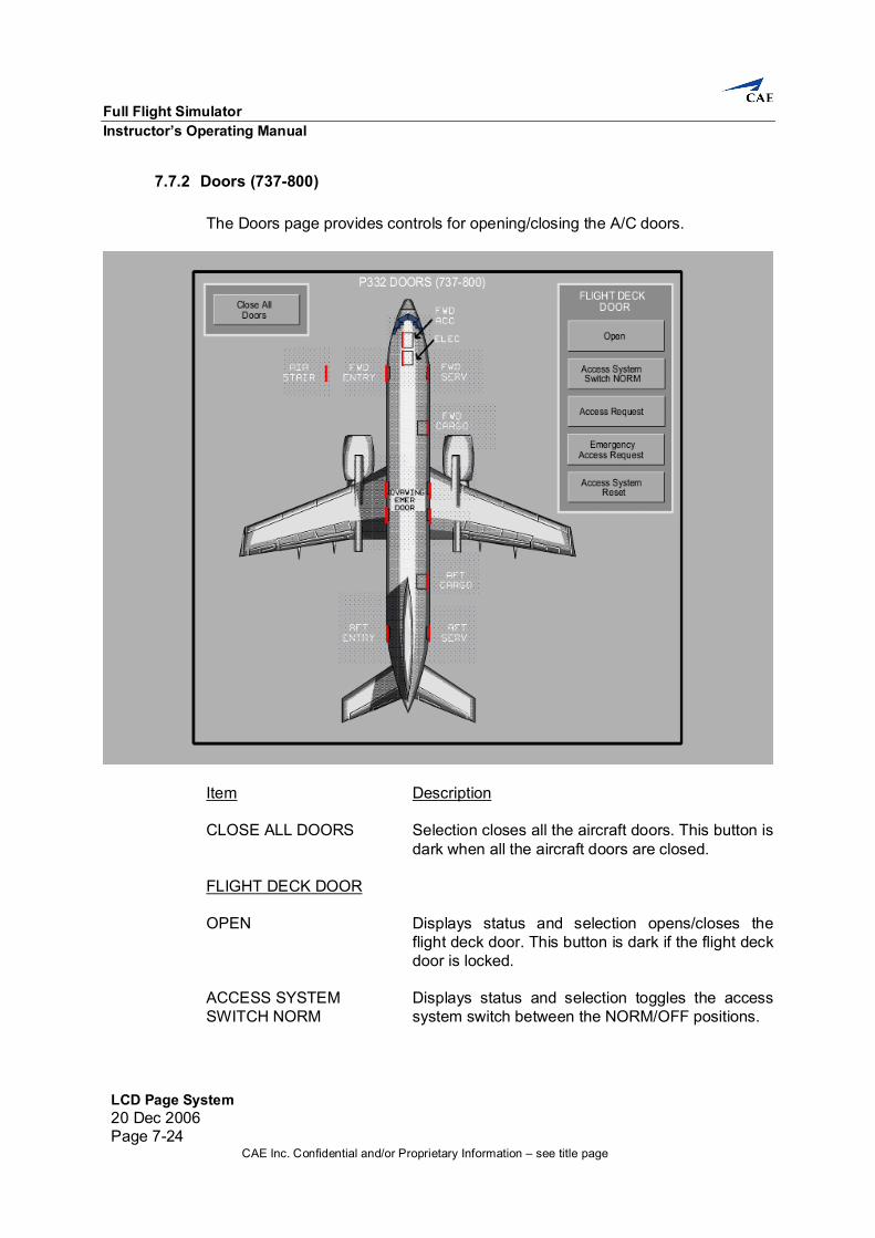
7.7.2 Doors (737-800) The Doors page provides controls for opening/closing the A/C doors.
Item Description CLOSE ALL DOORS Selection closes all the aircraft doors. This button is dark when all the aircraft doors are closed. FLIGHT DECK DOOR OPEN Displays status and selection opens/closes the flight deck door. This button is dark if the flight deck door is locked. ACCESS SYSTEM Displays status and selection toggles the access SWITCH NORM system switch between the NORM/OFF positions.
Instructor’s Operating Manual LCD Page System
LCD Page System20 Dec 2006
Page 7-25CAE Inc. Confidential and/or Proprietary Information – see title page
Item Description ACCESS REQUEST Displays status and selection emulates an access
request at the flight deck door. This button is dark if the flight deck door access keypad is deactivated because an access request has been denied or if the system control unit is unpowered. When selected, the button remains active for 2 seconds.
EMERGENCY ACCESS Displays status and selection emulates an REQUEST emergency access request at the flight deck door. This button if dark if the flight deck door access keypad is deactivated because an access request has been denied or if the system control unit is unpowered. When selected, the button remains active for 2 seconds. ACCESS SYSTEM RESET Displays status and selection resets the flight deck
door access system. This button is dark if a denied delay has not been activated by the crew via a cockpit panel selection. When selected, the button remains active for 2 seconds.
ALL DOORS Displays status and selection opens/closes the selected aircraft door.
Full Flight Simulator Instructor’s Operating Manual
LCD Page System 20 Dec 2006 Page 7-26
CAE Inc. Confidential and/or Proprietary Information – see title page
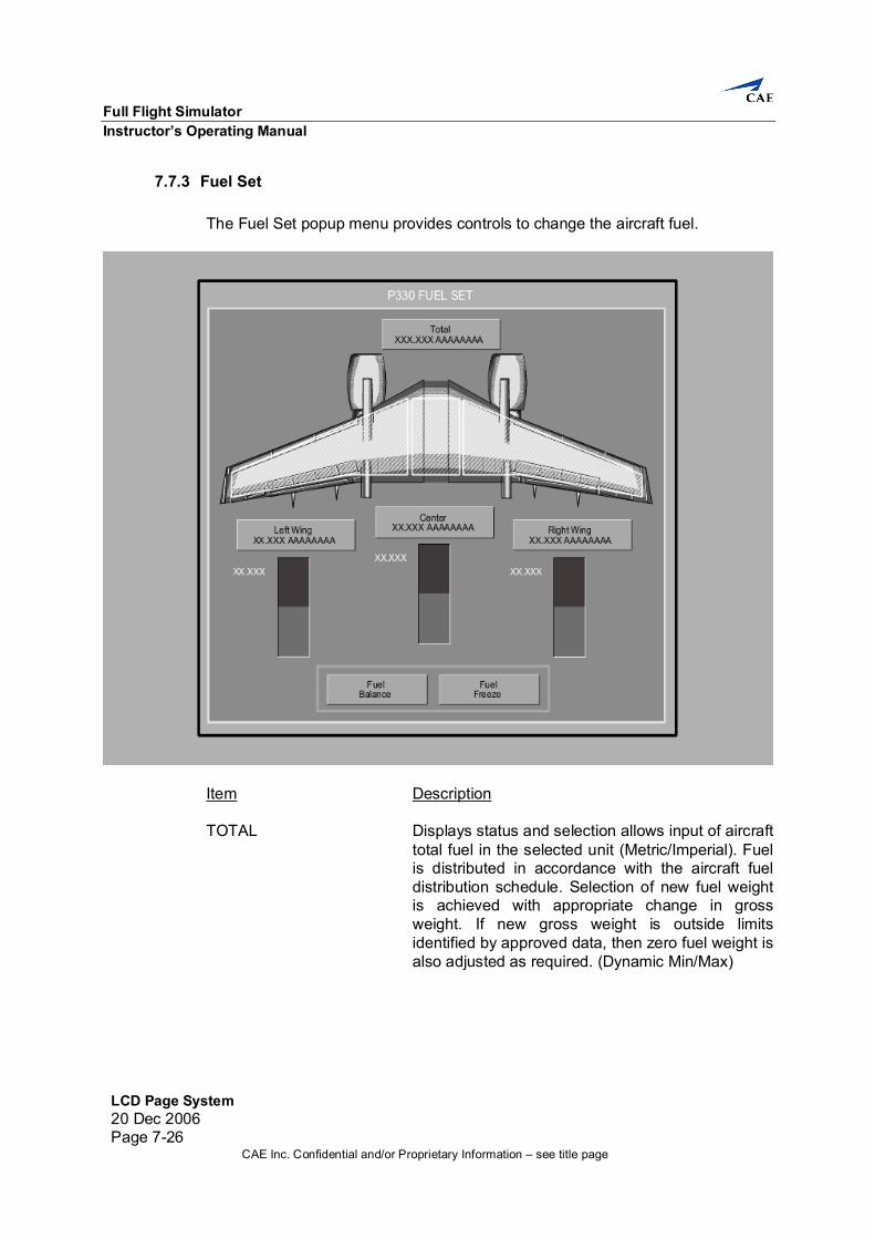
7.7.3 Fuel Set The Fuel Set popup menu provides controls to change the aircraft fuel.
Item Description TOTAL Displays status and selection allows input of aircraft
total fuel in the selected unit (Metric/Imperial). Fuel is distributed in accordance with the aircraft fuel distribution schedule. Selection of new fuel weight is achieved with appropriate change in gross weight. If new gross weight is outside limits identified by approved data, then zero fuel weight is also adjusted as required. (Dynamic Min/Max)
Instructor’s Operating Manual LCD Page System
LCD Page System20 Dec 2006
Page 7-27CAE Inc. Confidential and/or Proprietary Information – see title page
Item Description CENTER FUEL Displays status and selection allows input of fuel
quantity in the center fuel tank in the selected unit (Metric/Imperial). Selection of new fuel weight is achieved with appropriate change in gross weight. If new gross weight is outside limits identified by approved data, then zero fuel weight is also adjusted as required. (Dynamic Min/Max)
CENTER FUEL TANK Displays maximum value for center fuel tank. MAXIMUM LEFT WING Displays status and selection allows input of fuel
quantity in the left wing fuel tank in the selected unit (Metric/Imperial). Selection of new fuel weight is achieved with appropriate change in gross weight. If new gross weight is outside limits identified by approved data, then zero fuel weight is also adjusted as required. (Dynamic Min/Max)
LEFT WING FUEL Displays maximum value for left wing fuel tank. TANK MAXIMUM RIGHT WING Displays status and selection allows input of fuel
quantity in the right wing fuel tank in the selected unit (Metric/Imperial). Selection of new fuel weight is achieved with appropriate change in gross weight. If new gross weight is outside limits identified by approved data, then zero fuel weight is also adjusted as required. (Dynamic Min/Max)
RIGHT WING FUEL TANK Displays maximum value for right wing fuel MAXIMUM tank. FUEL BALANCE Displays status and selection balances fuel quantities in tanks. When selected, the button illuminates active for 2 seconds. FUEL FREEZE Displays status and selection activates/deactivates
fuel freeze. With fuel freeze active, all instruments other than fuel quantity indicate normally. All other aircraft systems remain unaffected except for the effects of frozen fuel. Refuel is possible when fuel freeze is active
Full Flight Simulator Instructor’s Operating Manual
LCD Page System 20 Dec 2006 Page 7-28
CAE Inc. Confidential and/or Proprietary Information – see title page
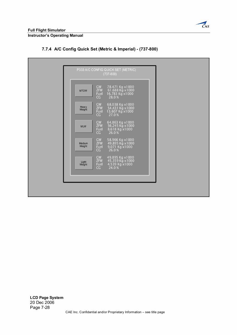
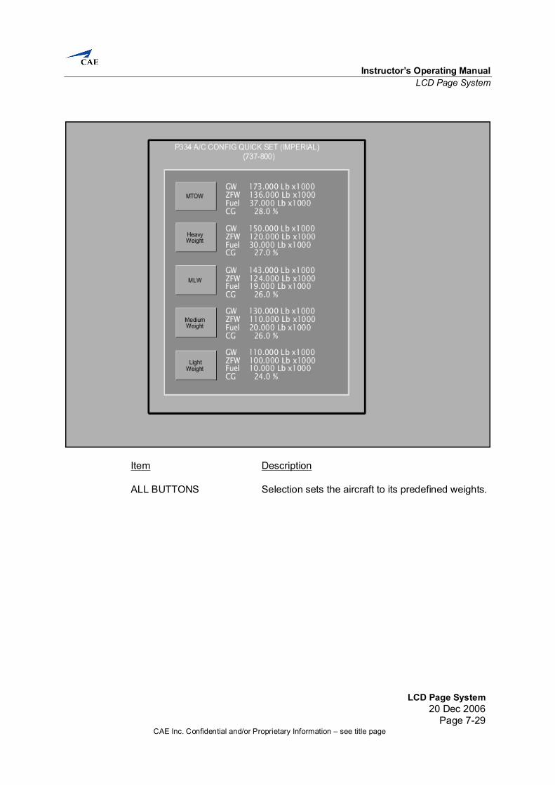
7.7.4 A/C Config Quick Set (Metric & Imperial) - (737-800)
Instructor’s Operating Manual LCD Page System
LCD Page System20 Dec 2006
Page 7-29CAE Inc. Confidential and/or Proprietary Information – see title page
Item Description ALL BUTTONS Selection sets the aircraft to its predefined weights.
Full Flight Simulator Instructor’s Operating Manual
LCD Page System 20 Dec 2006 Page 7-30
CAE Inc. Confidential and/or Proprietary Information – see title page
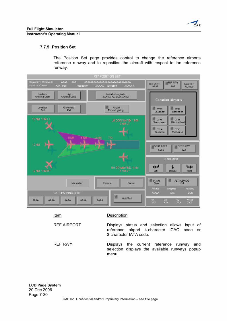
7.7.5 Position Set The Position Set page provides control to change the reference airports reference runway and to reposition the aircraft with respect to the reference runway.
Item Description REF AIRPORT Displays status and selection allows input of reference airport 4-character ICAO code or 3-character IATA code. REF RWY Displays the current reference runway and selection displays the available runways popup menu.
Instructor’s Operating Manual LCD Page System
LCD Page System20 Dec 2006
Page 7-31CAE Inc. Confidential and/or Proprietary Information – see title page
Item Description AUTO REF RUNWAY Displays status and selection toggles between auto
and manual mode. Auto allows automatic updates of the reference airfield to the nearest available runway until the nearest is the arrival airfield (then reference airfield locks to arrival airfield and runway). Selection unlocks if manual mode is selected or the arrival airfield is changed. In manual mode, the reference airfield and runway do not change unless there is new input from the instructor or lesson plan.
MEDIUM AIRWORK FL100 Displays status and selection repositions the
aircraft to the medium airwork FL100 position, followed by the execute button, relative to the current reference runway. Flight freeze is set at the end of the reposition.
The aircraft is configured as follows: Gear : Up Flap : Clean Speed: 250 KCAS Altitude: 10000 feet ASL Localizer Deviation: Centered Profile : Level Distance: 30 NM
HIGH AIRWORK FL350 Displays status and selection repositions the aircraft to the high airwork FL350 position, followed by the execute button, relative to the current reference runway. Flight freeze is set at the end of the reposition.
The aircraft is configured as follows:
Gear : Up Flap : Clean Speed: Mach 0.78 Altitude: 35000 ft pressure alt Localizer Deviation: Centered Profile : Level Distance: 100 NM
Full Flight Simulator Instructor’s Operating Manual
LCD Page System 20 Dec 2006 Page 7-32
CAE Inc. Confidential and/or Proprietary Information – see title page
Item Description LATITUDE/LONGITUDE Displays status and selection allows input SXX:XX:XX/SXXX:XX:XX of new aircraft latitude and longitude positions. LOCALIZER FAIL Displays status and selection fails the localizer of the reference runway. GLIDESLOPE FAIL Displays status and selection fails the glideslope of the reference runway. AIRPORT REPOS/ Selection displays the Airport Reposition popup LIGHTING menu. 12 NM, 1 NM LT Displays status and selection, followed by the execute button, repositions the aircraft to 12 nm, 1 nm left relative to the current reference runway. Flight freeze is set at the end of the reposition. Speed up is deactivated. The aircraft is configured as follows:
Gear : Up Flap : Flaps 5 Speed: 200 KCAS Altitude: 3000 ft AGL Localizer Deviation: 1 NM left Profile : Level Distance: 12 NM Intercept Angle: 30 degrees
LH DOWNWIND, 1NM, Displays status and selection, followed by the 3NM LT execute button, repositions the aircraft to LH downwind, 3 nm abeam and 1 nm prior to touchdown point, relative to the current reference runway. Flight freeze is set at the end of the reposition. Speed up is deactivated.
The aircraft is configured as follows: Gear : Up Flap : Flaps 5 Speed: 200 KCAS Altitude: 1500 feet AGL Localizer Deviation: 3 NM left Profile : Level Distance: 1 NM
Instructor’s Operating Manual LCD Page System
LCD Page System20 Dec 2006
Page 7-33CAE Inc. Confidential and/or Proprietary Information – see title page
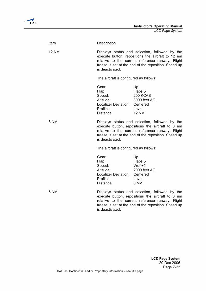
Item Description 12 NM Displays status and selection, followed by the
execute button, repositions the aircraft to 12 nm relative to the current reference runway. Flight freeze is set at the end of the reposition. Speed up is deactivated.
8 NM Displays status and selection, followed by the
execute button, repositions the aircraft to 8 nm relative to the current reference runway. Flight freeze is set at the end of the reposition. Speed up is deactivated.
The aircraft is configured as follows: Gear : Up Flap : Flaps 5 Speed: Vref +5 Altitude: 2000 feet AGL Localizer Deviation: Centered Profile : Level Distance: 8 NM 6 NM Displays status and selection, followed by the
execute button, repositions the aircraft to 6 nm relative to the current reference runway. Flight freeze is set at the end of the reposition. Speed up is deactivated.
Full Flight Simulator Instructor’s Operating Manual
LCD Page System 20 Dec 2006 Page 7-34
CAE Inc. Confidential and/or Proprietary Information – see title page
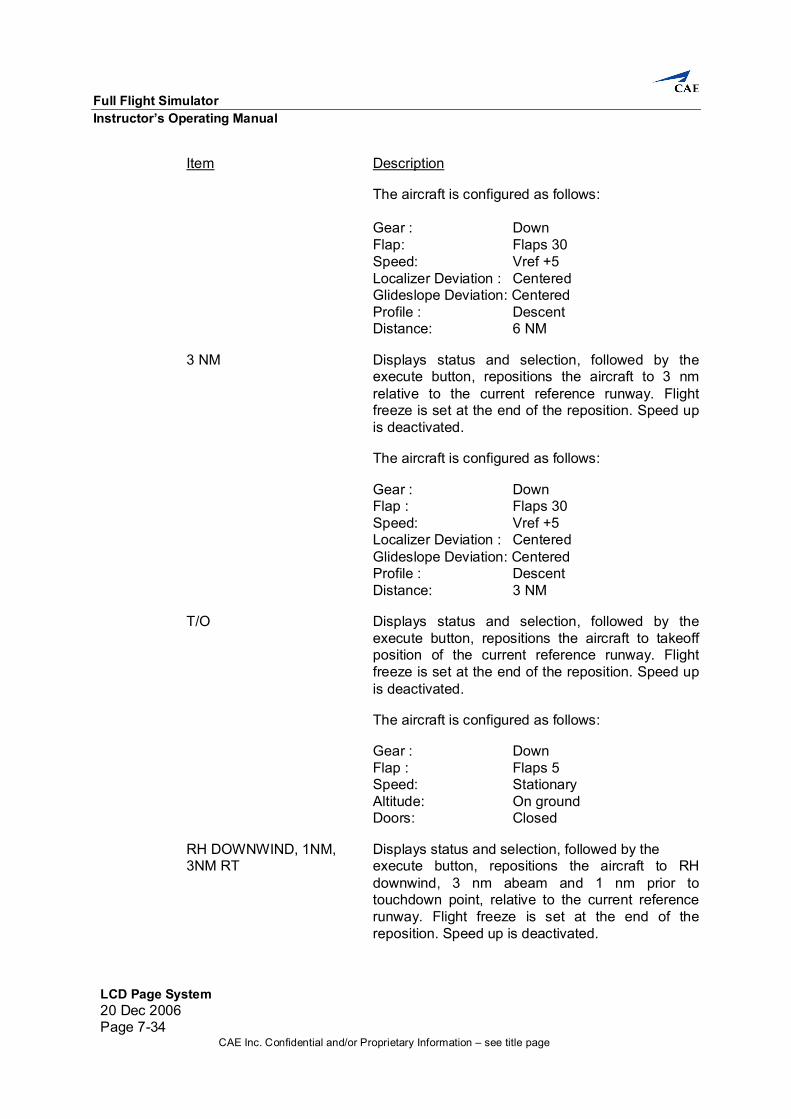
Item Description
The aircraft is configured as follows: Gear : Down Flap: Flaps 30 Speed: Vref +5 Localizer Deviation : Centered Glideslope Deviation: Centered Profile : Descent Distance: 6 NM
3 NM Displays status and selection, followed by the
execute button, repositions the aircraft to 3 nm relative to the current reference runway. Flight freeze is set at the end of the reposition. Speed up is deactivated.
The aircraft is configured as follows: Gear : Down Flap : Flaps 30 Speed: Vref +5 Localizer Deviation : Centered Glideslope Deviation: Centered Profile : Descent Distance: 3 NM
T/O Displays status and selection, followed by the
execute button, repositions the aircraft to takeoff position of the current reference runway. Flight freeze is set at the end of the reposition. Speed up is deactivated.
The aircraft is configured as follows: Gear : Down Flap : Flaps 5 Speed: Stationary Altitude: On ground Doors: Closed
RH DOWNWIND, 1NM, Displays status and selection, followed by the 3NM RT execute button, repositions the aircraft to RH downwind, 3 nm abeam and 1 nm prior to touchdown point, relative to the current reference runway. Flight freeze is set at the end of the reposition. Speed up is deactivated.
Instructor’s Operating Manual LCD Page System
LCD Page System20 Dec 2006
Page 7-35CAE Inc. Confidential and/or Proprietary Information – see title page
Item Description
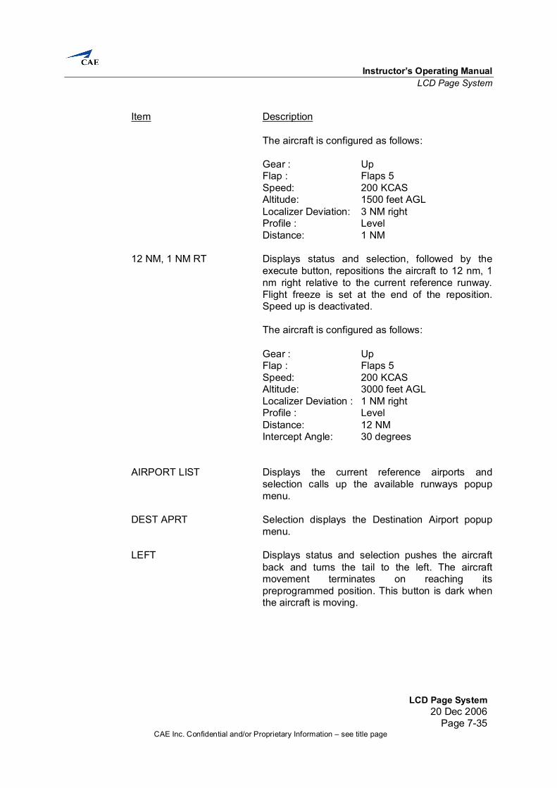
The aircraft is configured as follows: Gear : Up Flap : Flaps 5 Speed: 200 KCAS Altitude: 1500 feet AGL Localizer Deviation: 3 NM right Profile : Level Distance: 1 NM
12 NM, 1 NM RT Displays status and selection, followed by the
execute button, repositions the aircraft to 12 nm, 1 nm right relative to the current reference runway. Flight freeze is set at the end of the reposition. Speed up is deactivated.
The aircraft is configured as follows: Gear : Up Flap : Flaps 5 Speed: 200 KCAS Altitude: 3000 feet AGL Localizer Deviation : 1 NM right Profile : Level Distance: 12 NM Intercept Angle: 30 degrees
AIRPORT LIST Displays the current reference airports and
selection calls up the available runways popup menu.
DEST APRT Selection displays the Destination Airport popup
menu. LEFT Displays status and selection pushes the aircraft
back and turns the tail to the left. The aircraft movement terminates on reaching its preprogrammed position. This button is dark when the aircraft is moving.
Full Flight Simulator Instructor’s Operating Manual
LCD Page System 20 Dec 2006 Page 7-36
CAE Inc. Confidential and/or Proprietary Information – see title page
Item Description STRAIGHT Displays status and selection pushes the aircraft
back. The aircraft movement terminates on reaching its preprogrammed position. This button is dark when the aircraft is moving.
RIGHT Displays status and selection pushes the aircraft
back and turns the tail to the right. The aircraft movement terminates on reaching its preprogrammed position. This button is dark when the aircraft is moving.
MARSHALLER Displays status and selection activates/deactivates
marshaller (i.e. he appears or disappears from the visual), who signals in the aircraft to the gate when the aircraft is within an appropriate position to the gate.
EXECUTE Displays status and selection executes the selected
reposition. This button is dark if no reposition has been selected.
CANCEL Displays status and selection cancels the selected
reposition. This button is dark if no reposition has been selected.
POSN SLEW Selection displays the Position Slew popup menu. ALT/IAS/HDG SET Selection displays the Alt/IAS/Hdg Set popup
menu. ALT Displays current aircraft height above sea level in
feet. IAS Displays current aircraft indicated airspeed in knots. HDG Displays current aircraft magnetic heading.
Instructor’s Operating Manual LCD Page System
LCD Page System20 Dec 2006
Page 7-37CAE Inc. Confidential and/or Proprietary Information – see title page
Item Description GATE/PARKING SPOT GATE/PARKING SPOT Displays status and selection repositions the
aircraft to the respective gate/parking spot position, followed by the execute button. Flight freeze is set at the end of the reposition.
The aircraft is configured as follows: Gear : Down Doors: 1L, fwd and aft cargo doors
open.
HOLD/TAXI Selection displays the requested popup menu. V1 Displays V1 speed in knots. VR Displays VR speed in knots. V2 Displays V2 speed in knots. VREF Displays Vref speed in knots. ALL BUTTONS Selection sets new reference airport and brings up
the runway popup selection. The runway popup name displays the runways available for the reference airport.
Full Flight Simulator Instructor’s Operating Manual
LCD Page System 20 Dec 2006 Page 7-38
CAE Inc. Confidential and/or Proprietary Information – see title page
7.7.6 Runways
Item Description RUNWAY INDEX NO Displays status and selection sets all the runway
lights for the selected runway to the automatic default value. This button is transparent if the runway does not exist for the selected reference airport. This button is dark if it is not the reference runway for the generic airport.
Instructor’s Operating Manual LCD Page System
LCD Page System20 Dec 2006
Page 7-39CAE Inc. Confidential and/or Proprietary Information – see title page
7.7.7 Destination Airport Displays the current list of airports and allows selection of the destination airport.
Full Flight Simulator Instructor’s Operating Manual
LCD Page System 20 Dec 2006 Page 7-40
CAE Inc. Confidential and/or Proprietary Information – see title page
Item Description DESTINATION AIRPORT Displays status and selection allows input of the destination airport 4-character ICAO code or 3-character IATA code. ALL AIRPORT BUTTONS Selection sets the new destination airport and
brings up the runway popup selection. The runway popup name displays the runways available for the destination airport.
Instructor’s Operating Manual LCD Page System
LCD Page System20 Dec 2006
Page 7-41CAE Inc. Confidential and/or Proprietary Information – see title page
7.7.8 Destination Runways The Destination Runways popup menu displays the runways available for the current destination airport.
Item Description RUNWAY Displays the designation of the runways available at that current destination airport. Selection designates that runway as the current destination runway. Buttons with no runway designation are blank.
Full Flight Simulator Instructor’s Operating Manual
LCD Page System 20 Dec 2006 Page 7-42
CAE Inc. Confidential and/or Proprietary Information – see title page
7.7.9 ALT/IAS/HDG Set
Item Description ALTITUDE Displays status and selection allows input of aircraft
altitude in feet. Input may be done through the keypad by selecting the ALT box or via the respective bar chart.
ALTITUDE SCROLL BAR Displays status and selection allows the instructor
to input an aircraft altitude in feet via the respective scroll bar.
Instructor’s Operating Manual LCD Page System
LCD Page System20 Dec 2006
Page 7-43CAE Inc. Confidential and/or Proprietary Information – see title page
Item Description AIRSPEED Displays status and selection allows the instructor
to input an indicated airspeed in knots. The aircraft is trimmed at the requested speed. Flap and gear position will be driven as required so as to not create an overspeed condition. Flight freeze is set once complete.
AIRSPEED SCROLL BAR Displays status and selection allows the instructor
to input an indicated airspeed in knots via the respective scroll bar.
MACH Displays status and selection allows input of the
aircraft mach number. The aircraft is trimmed at the requested mach number. Flap and gear position will be driven as required so as to not create an overspeed condition. Flight freeze is set once complete. (Min = 0, Max = 0.85)
HEADING Displays status and selection allows input of the
magnetic heading of the aircraft. No other parameters are affected.
EXECUTE Displays status and selection slews the aircraft
speed or altitude to the selected amount. CANCEL Displays status and selection cancels the selected
items that were to be executed.
Full Flight Simulator Instructor’s Operating Manual
LCD Page System 20 Dec 2006 Page 7-44
CAE Inc. Confidential and/or Proprietary Information – see title page
7.7.10 Position Slew The Position Slew popup menu provides controls to slew the aircraft. Slewing is possible while position freeze is on. Below 100 feet above ground the aircraft height above ground will be maintained as position is slewed.
Item Description NORTH Displays status and selection slews the aircraft to
the north. WEST Displays status and selection slews the aircraft to
the west. EAST Displays status and selection slews the aircraft to
the east. SOUTH Displays status and selection slews the aircraft to
the south.
Instructor’s Operating Manual LCD Page System
LCD Page System20 Dec 2006
Page 7-45CAE Inc. Confidential and/or Proprietary Information – see title page
Item Description SLEW RATE Displays the current rate at which the slews
function. RATE SCROLL BAR Displays status and selection allows the instructor
to input a rate at which the slews will function. (Min = 1, Max = 5) FORWARD Displays status and selection slews the aircraft
forward. LEFT Displays status and selection slews the aircraft left. RIGHT Displays status and selection slews the aircraft
right. BACK Displays status and selection slews the aircraft
back.
Full Flight Simulator Instructor’s Operating Manual
LCD Page System 20 Dec 2006 Page 7-46
CAE Inc. Confidential and/or Proprietary Information – see title page
7.7.11 Hold/Taxi
Item Description HOLD/TAXI Displays status and selection, followed by the
execute button, repositions the aircraft to the corresponding hold/taxi position. Flight freeze is set at the end of the reposition. Speed up is deactivated.
The aircraft is configured as follows:
Gear : Down Doors: Closed
Instructor’s Operating Manual LCD Page System
LCD Page System20 Dec 2006
Page 7-47CAE Inc. Confidential and/or Proprietary Information – see title page
Item Description EXECUTE Displays status and selection executes the selected
reposition. Speed up is deactivated. This button is dark if no reposition has been selected.
CANCEL Displays status and selection cancels the selected
reposition. This button is dark if no reposition has been selected.
Full Flight Simulator Instructor’s Operating Manual
LCD Page System 20 Dec 2006 Page 7-48
CAE Inc. Confidential and/or Proprietary Information – see title page
7.7.12 Airport Repos/Lighting
Item Description EXECUTE Displays status and selection executes the selected
reposition. This button is dark if no reposition has been selected.
CANCEL Displays status and selection cancels the selected
reposition. This button is dark if no reposition has been selected.
Instructor’s Operating Manual LCD Page System
LCD Page System20 Dec 2006
Page 7-49CAE Inc. Confidential and/or Proprietary Information – see title page
7.7.13 Environment Set The Environment Set page provides controls to change environment conditions (e.g., QNH, runway conditions, temperature, special effects and visual controls). It also allows modification of Cloud Layers 1 and 2 cloud top, ceiling and cloud types, visibility, RVR and fog.
Item Description VISUAL CONTROLS VISUAL Displays status and selection turns the visual
system On/Off. TIME OF DAY Selection displays the Time of Day popup menu.
Full Flight Simulator Instructor’s Operating Manual
LCD Page System 20 Dec 2006 Page 7-50
CAE Inc. Confidential and/or Proprietary Information – see title page
Item Description DAWN Displays status and selection activates dawn
conditions on the visual display. Dawn, Day, Dusk and Night are mutually exclusive.
DUSK Displays status and selection activates dusk
conditions on the visual display. Dawn, Day, Dusk and Night are mutually exclusive.
DAY Displays status and selection activates day
conditions on the visual display. Dawn, Day, Dusk and Night are mutually exclusive.
NIGHT Displays status and selection activates night
conditions on the visual display. Dawn, Day, Dusk and Night are mutually exclusive.
STOP BAR GO Displays status and selection turns off all the stop
bar lights at the airport. STOP BAR STOP Displays status and selection turns on all the stop
bar lights at the airport. APRT LIGHTING Selection displays the Airport Lighting popup menu. TCAS Selection displays the TCAS popup menu. This
button is dark if gates traffic is active. GROUND TRAFFIC Selection displays the Ground Traffic popup menu. RESET WIND GRAD Displays status and selection resets the wind
profile. When selected, the button remains active for two seconds.
CIRRUS Displays status and selection sets cirrus clouds at
high altitude. No control of altitude available. RESET TEMP GRAD Displays status and selection resets the
temperature profile. When selected, the button remains active for two seconds.
WIND DDD/XXX Displays status and selection allows input of upper
level magnetic wind direction and wind speed. (Min = 1, Max = 360 Degrees) wind direction (Min = 0, Max = 200 Knots) wind speed
Instructor’s Operating Manual LCD Page System
LCD Page System20 Dec 2006
Page 7-51CAE Inc. Confidential and/or Proprietary Information – see title page
Item Description ALTITUDE Displays status and selection allows input of upper
level altitude for wind speed and direction. (Dynamic Min, Max = 45000)
VISIBILITY Displays status and selection allows input of above
cloud visibility in the selected unit (kilometers/statute miles).
(Min = 0, Max = Dynamic) ISA DEV Displays status and selection allows input of the
temperature deviation from ISA at the corresponding level in degrees Celsius.
(Dynamic Min/Max) TEMP Displays status and selection allows input of high
altitude temperature in the selected unit (Celsius/Fahrenheit). (Dynamic Min/Max)
OVERCAST Displays status and selection sets cloud layer 2 to
overcast. SCATTERED Displays status and selection sets cloud layer 2 to
scattered. This button becomes dark whenever Scattered or Broken is selected on another cloud layer.
BROKEN Displays status and selection sets cloud layer 2 to
broken. This button becomes dark whenever Scattered or Broken is selected on another cloud layer.
CLOUD TOP ASL - LAYER 2 Displays status and selection allows input of cloud
top level for cloud layer 2 in geometric feet above sea level. If scattered or broken is active, the top becomes unavailable because the cloud thickness is predefined. (Dynamic Min/Max)
Full Flight Simulator Instructor’s Operating Manual
LCD Page System 20 Dec 2006 Page 7-52
CAE Inc. Confidential and/or Proprietary Information – see title page
Item Description CLOUD BASE ASL - Displays status and selection allows input of cloud LAYER 2 base level for cloud layer 2 in geometric feet above sea level. (Dynamic Min/Max) WIND DDD/XXX Displays status and selection allows input of
intermediate 2 magnetic wind direction and wind speed.
(Min = 1, Max = 360 Degrees) wind direction (Min = 0, Max = 200 Knots) wind speed ALTITUDE Displays status and selection allows input of
intermediate 2 altitude for wind speed and direction. (Dynamic Min/Max)
VISIBILITY Displays status and selection allows input of
between cloud visibility in the selected unit (kilometers/statute miles).
(Min = 0, Max = Dynamic) ISA DEV Displays status and selection allows input of the
temperature deviation from ISA at the corresponding level in degrees Celsius.
(Dynamic Min/Max) TEMP Displays status and selection allows input of
intermediate 2 temperature in the selected unit (Celsius/Fahrenheit). (Dynamic Min/Max)
OVERCAST Displays status and selection sets cloud layer 1 to
overcast. SCATTERED Displays status and selection sets cloud layer 1 to
scattered. This button becomes dark whenever Scattered or Broken is selected on another cloud layer.
BROKEN Displays status and selection sets cloud layer 1 to
broken. This button becomes dark whenever Scattered or Broken is selected on another cloud layer.
SCUD Displays status and selection activates/deactivates
scud for overcast clouds at cloud layer 1.
Instructor’s Operating Manual LCD Page System
LCD Page System20 Dec 2006
Page 7-53CAE Inc. Confidential and/or Proprietary Information – see title page
Item Description CLOUD TOP ASL - Displays status and selection allows input of cloud LAYER 1 top level for cloud layer 1 in geometric feet above sea level. If scattered or broken is active, the top becomes unavailable because the cloud thickness is predefined. (Dynamic Min/Max) CLOUD BASE AGL - Displays status and selection allows input of cloud LAYER 1 base level for cloud layer 1 in geometric feet above ground. (Dynamic Min/Max) WIND Selection displays the graphical Surface Wind
popup menu. WIND GUST RELATIVE Displays status of wind gust relative in knots. VISIBILITY Displays status and selection allows input of below
cloud visibility in the selected unit (kilometers/statute miles).
(Min = 0, Max = Dynamic) Maximum visibility is limited if rain is activated (15 nm for light rain, 5 nm for moderate rain, 1 nm for heavy rain). TEMP Displays status and selection allows input of airfield
temperature in the selected unit (Celsius/Fahrenheit). The entire temperature profile will be offset by the change in the ground temperature. (Dynamic Min/Max)
PATCHY FOG Displays status and selection activates/deactivates
patchy fog. When patchy fog is activated, a default RVR minimum and RVR maximum are set.
Full Flight Simulator Instructor’s Operating Manual
LCD Page System 20 Dec 2006 Page 7-54
CAE Inc. Confidential and/or Proprietary Information – see title page
Item Description RVR Displays status and selection allows input of the
runway visual range in the selected unit (meters/feet). This button is only available when patchy fog is not active.
(Min = 0, Max = 3045 meters) (Min = 0, Max = 9990 feet) FOG TOP Displays status and selection allows input of fog top
in geometric feet above ground. (Dynamic Min/Max)
ROUGHNESS Displays the degree of runway roughness (0-5). QNH Displays status and selection allows input of sea
level barometric pressure in the selected unit (hectopascals/inches Hg).
(Min = 949, Max = 1070 hPa) (Min = 28.05, Max = 31.59 inHg) QFE Displays status and selection allows input of field
barometric pressure in the selected unit (hectopascals/inches Hg).
(Min = 949, Max = 1070 hPa) (Min = 28.05, Max = 31.59 inHg) RWY CONDITIONS Selection displays the Runway Conditions popup
menu. CONTAMINATION DESC Displays the runway contamination (dry, wet, 1/4 in.
water, 1/4 in. slush, 1/2 in. slush, snow, ice, patchy ice, and patchy wet).
Instructor’s Operating Manual LCD Page System
LCD Page System20 Dec 2006
Page 7-55CAE Inc. Confidential and/or Proprietary Information – see title page
Item Description ATMOSPHERE WX EFFECTS Displays active if Wx Effects is selected and
selection displays the Wx Effects popup menu. MICROBURST Selection displays the Microburst popup menu. The
button is active if a microburst is activated. PREDICTIVE WS Selection displays the Predictive Windshears
popup menu. The button is active if a predictive windshear is activated. This button is dark if a non-predictive windshear is activated.
WINDSHEARS Selection displays the Non-Predictive Windshears
popup menu. The button is active if a non-predictive windshear is activated. This button is dark if a predictive windshear is activated.
TURBULENCE Displays active if turbulence is selected and
selection displays the Turbulence popup menu. TURBULENCE TYPE Displays status of turbulence type. TURBULENCE INTENSITY Displays the turbulence intensity (Light, Moderate,
Heavy). ICING Displays active if icing intensity is selected and
selection displays the Icing popup menu. ICING INTENSITY Displays the icing intensity (Light, Moderate,
Severe). STORM CLOUDS Selection displays the map page with storm front
controls. This button is red if a storm cloud is selected.
WIND AT A/C DDD/XXX Displays status and selection allows input of
magnetic wind direction and wind speed at the aircraft. (Min = 1, Max = 360 Degrees) wind direction (Min = 0, Max = 50 Knots) wind speed
Full Flight Simulator Instructor’s Operating Manual
LCD Page System 20 Dec 2006 Page 7-56
CAE Inc. Confidential and/or Proprietary Information – see title page
Item Description OAT Displays status and selection allows input of
outside air temperature in the selected unit (Celsius/Fahrenheit). The entire temperature profile will be offset by the change in the outside air temperature. (Dynamic Min/Max)
PRESET WX CAVOK Displays status and selection activates CAVOK
conditions on the visual display. CAVOK conditions:
a) No cloud base below 5000 feet; no cumulonimbus.
b) Visibility 6 statute miles or more. c) No precipitation, thunderstorms, shallow fog, or
low drifting snow. NON-PREC Displays status and selection activates NON-PREC
800-2sm/800-3.2km conditions on the visual display. In case of metric, will display 800-3km instead of 800-3.2km.
CAT I Displays status and selection activates CAT I
conditions on the visual display. CAT II Displays status and selection activates CAT II
conditions on the visual display. CAT IIIA Displays status and selection activates CAT IIIA
conditions on the visual display. CAT IIIA conditions: a) Ceiling less than 100 feet b) RVR 200 meters (656 feet) MIN T/O RVR Displays status and selection activates MIN T/O RVR conditions on the visual display. 0/0 Displays status and selection activates 0/0 conditions on the visual display.
Instructor’s Operating Manual LCD Page System
LCD Page System20 Dec 2006
Page 7-57CAE Inc. Confidential and/or Proprietary Information – see title page
Item Description 1000-3SM/1000-5KM Displays status and selection activates CIRCLING
1000-3sm/1000-4.82km conditions on the visual display. In case of metric, will display 1000-5km instead of 1000-4.82km.
Full Flight Simulator Instructor’s Operating Manual
LCD Page System 20 Dec 2006 Page 7-58
CAE Inc. Confidential and/or Proprietary Information – see title page
7.7.14 Time of Day The Time of Day popup menu provides controls for modifying the current time, month and day and for setting sun, moon and horizon visual effects.
Item Description TIME Displays status and selection allows input of time of
day in hours and minutes. MONTH/DAY XX/XX Displays status and selection allows input of month
and day. SPEED UP FACTOR Displays status and selection allows input of
time-of-day speed factor which affects the progression of time.
Instructor’s Operating Manual LCD Page System
LCD Page System20 Dec 2006
Page 7-59CAE Inc. Confidential and/or Proprietary Information – see title page
Item Description ENABLE SUN Displays status and selection enables sun effects
on the visual display. ENABLE MOON Displays status and selection enables moon effects
on the visual display.
Full Flight Simulator Instructor’s Operating Manual
LCD Page System 20 Dec 2006 Page 7-60
CAE Inc. Confidential and/or Proprietary Information – see title page
7.7.15 Airport Lighting The Airport Lighting popup menu displays status and provides controls for modifying airport light intensities for any runway of the reference airport.
Item Description LIGHTING STATUS REFERENCE AIRPORT Displays runway name from the list of runways RUNWAY for the selected reference airport. RUNWAY LIGHTS Displays the intensity of the runway lights for the INTENSITY selected runway. If all of the light intensities on that runway are not the same value, a * will be displayed.
Instructor’s Operating Manual LCD Page System
LCD Page System20 Dec 2006
Page 7-61CAE Inc. Confidential and/or Proprietary Information – see title page
Item Description RUNWAY Selection displays the Runway Lighting popup
menu. VISUAL LANDING AID Displays status and selection allows input of VLA
lighting brightness intensity. (Min = 0, Max = 5) APPROACH Displays status and selection allows input of
approach lighting intensity for the active reference runway. (Min = 0, Max = 5)
CENTERLINE Displays status and selection allows input of
centerline lighting intensity. (Min = 0, Max = 5) STROBE Displays status and selection allows input of the
strobe lighting intensity for either end of the runway. (Min = 0, Max = 5)
TD ZONE Displays status and selection allows input of touch
down zone lighting intensity. (Min = 0, Max = 5) RANDOM INTENSITY Displays status and selection enables/disables the
runway lighting system to have random intensity lighting. Selection affects random lighting for Edge and Ends, Centerline, and TD Zone.
EDGE AND ENDS Displays status and selection allows input of
runway edge and ends lighting intensity. (Min = 0, Max = 5) REILS Displays status and selection allows input of reils
brightness intensity. (Min = 0, Max = 5) ALL RUNWAY LIGHTS Displays status and selection allows input of all
lighting intensities for the active visual lighting runway (i.e., horizon, reils, centerline/touchdown, runway, VLA, approach and environment lighting). A star is displayed when all light intensities are not the same for the selected runway.
(Min = 0, Max = 5)
Full Flight Simulator Instructor’s Operating Manual
LCD Page System 20 Dec 2006 Page 7-62
CAE Inc. Confidential and/or Proprietary Information – see title page
Item Description TAXI Displays status and selection allows input of all taxi
light intensities for the active airport. (Min = 0, Max = 5) STOP BAR GO Displays status and selection turns off all the stop
bar lights at the airport. STOP BAR STOP Displays status and selection turns on all the stop
bar lights at the airport. CITY LIGHTS Displays status and selection allows input of
environment light intensity for the active airport. (Min = 0, Max = 5)
PILOT CONTROL Displays status and selection allows the pilot to
control airport lighting.
Instructor’s Operating Manual LCD Page System
LCD Page System20 Dec 2006
Page 7-63CAE Inc. Confidential and/or Proprietary Information – see title page
7.7.16 Runway Lights The Runway Lights popup menu provides controls for selecting runways associated with the current reference airport. Each runway can be set with different lighting.
Item Description RUNWAY INDEX NO Displays status and selection sets the described
runway as the current runway for which lighting will be set.
Full Flight Simulator Instructor’s Operating Manual
LCD Page System 20 Dec 2006 Page 7-64
CAE Inc. Confidential and/or Proprietary Information – see title page
7.7.17 TCAS How to set up scenario intruder for TCAS training: Step 1: Select direction of scenario intruder. Sets direction of the intruder
relative to own A/C. Step 2: Select level change scenario intruder. Sets change of rate of climb
of the intruder. Step 3: Select transponder type of scenario intruder. Sets transponder
mode of intruder.
Mode A: Intruders will not report their altitude. On the TCAS display, the intruder symbol will be shown without any altitude tag. Therefore no Resolution Advisory is issued by TCAS.
Mode C/S: The normal mode for TCAS. The intruders will report their altitude and TCAS will issue Traffic Advisory and Resolution Advisory if any.
Step 4: Select scenario advisory. Very important: the own A/C must be in
stable path (i.e. own A/C must be in stable climb or descent up to a max V/S described below, stable heading and constant speed).
Scenario 1: Traffic Advisory only TCAS issues a traffic
advisory. Number of intruders specified in scenario is 1. Own A/C V/S max limit +-1000fpm.
Scenario 2: Resolution Advisory, No Climb/No Descend TCAS issues a resolution advisory. Number of intruders specified in scenario is 2. Own A/C V/S max limit +-200fpm.
Scenario 3: Resolution Advisory, Climb/Descend TCAS issues a resolution advisory. Number of intruders specified in scenario is 1. Own A/C V/S max limit +-1000fpm.
Scenario 4: Resolution Advisory, Requiring Further Action By Crew (Single Threat) TCAS issues a resolution advisory. Number of intruders specified in scenario is 1. Own A/C V/S max limit +-1000fpm.
Scenario 5: Resolution Advisory, Requiring Further Action By Crew (Multiple Threat) TCAS issues a resolution advisory. Number of intruders specified in scenario is 2. Own A/C V/S max limit +-1000fpm.
Step 5: Once all these selections have been made, press
the Activate Scenario button.
Instructor’s Operating Manual LCD Page System
LCD Page System20 Dec 2006
Page 7-65CAE Inc. Confidential and/or Proprietary Information – see title page
Item Description 1. Select Direction of Scenario Intruder AHEAD LEFT Displays status and selection sets the approaching
direction of the intruder aircraft. (Bearing = -45 deg) AHEAD Displays status and selection sets the approaching
direction of the intruder aircraft. (Bearing = 0 deg) AHEAD RIGHT Displays status and selection sets the approaching
direction of the intruder aircraft. (Bearing = +45 deg)
Full Flight Simulator Instructor’s Operating Manual
LCD Page System 20 Dec 2006 Page 7-66
CAE Inc. Confidential and/or Proprietary Information – see title page
Item Description ABEAM LEFT Displays status and selection sets the approaching
direction of the intruder aircraft. (Bearing = -90 deg) ABEAM RIGHT Displays status and selection sets the approaching
direction of the intruder aircraft. (Bearing = +90 deg)
BEHIND LEFT Displays status and selection sets the approaching
direction of the intruder aircraft. (Bearing = -145 deg)
BEHIND RIGHT Displays status and selection sets the approaching
direction of the intruder aircraft. (Bearing = +145 deg)
2. Select Level Change of Scenario Intruder DESCEND Displays status and selection sets the level change
of the intruder aircraft, (climb, same level, descend). (Intruder ALT = higher, Intruder V/S = descending)
LEVEL Displays status and selection sets the level change
of the intruder aircraft, (climb, same level, descend). (Intruder ALT = N/A, Intruder V/S = level)
CLIMB Displays status and selection sets the level change
of the intruder aircraft, (climb, same level, descend). (Intruder ALT = lower, Intruder V/S = climbing)
3. Select Transponder Type of Scenario Intruder MODE A Displays status and selection allows input of aircraft
transponder or type for the random aircraft. MODE C/S Displays status and selection allows input of aircraft
transponder or type for the random aircraft.
Instructor’s Operating Manual LCD Page System
LCD Page System20 Dec 2006
Page 7-67CAE Inc. Confidential and/or Proprietary Information – see title page
Item Description 4. Select Scenario 1 Displays status and selection sets the
traffic/resolution advisory (single threat). 2 Displays status and selection sets the resolution
advisory no climb/no descend (dual threats). 3 Displays status and selection sets the resolution
advisory climb/descend (single threat). 4 Displays status and selection sets the resolution
advisory requiring further action by crew (single threat).
5 Displays status and selection sets the resolution
advisory requiring further action by crew (dual threats).
COLLISION TIME Displays amount of time remaining prior to collision
with the nearest intruder. ACTIVATE SCENARIO Displays status and selection activates/deactivates
the scenario intruder. The button is dark when the aircraft is not stable.
Random Intruder Options NUMBER OF RANDOM Displays status and selection allows input of the
number of random intruders. (Min = 0, Max = Dynamic) MODE A Displays status and selection activates/deactivates
the random intruder equipped with transponder but no altitude reporting.
MODE C/S Displays status and selection activates/deactivates
the random intruder equipped with transponder and all altitude reporting.
MIXED Displays status and selection activates/deactivates
the random intruder in a random selection of transponder mode.
Full Flight Simulator Instructor’s Operating Manual
LCD Page System 20 Dec 2006 Page 7-68
CAE Inc. Confidential and/or Proprietary Information – see title page
7.7.18 Ground Traffic The Ground Traffic popup menu displays a summary of previously recorded ground traffic scenarios and provides controls for activating/deactivating the scenario on the visual display.
Item Description REFERENCE AIRPORT Displays the ICAO code of the reference airport. RUNWAY Displays the name of the reference runway. GROUND TRAFFIC Displays status and selection activates specific MODEL model of ground traffic. MODEL NAME Displays the model name of the ground traffic
scenario.
Instructor’s Operating Manual LCD Page System
LCD Page System20 Dec 2006
Page 7-69CAE Inc. Confidential and/or Proprietary Information – see title page
Item Description MODELS VISUAL ROUTE Displays the route description of the ground traffic
scenario. START/STOP Displays status and selection activates vehicle
start/stop button. The model returns to the start point if not stopped prior to the end of the recording.
Full Flight Simulator Instructor’s Operating Manual
LCD Page System 20 Dec 2006 Page 7-70
CAE Inc. Confidential and/or Proprietary Information – see title page
7.7.19 Surface Wind The Surface Wind popup menu displays a circle with vectors representing the current surface wind speed and direction. Wind speed is represented by the length of the vectors. Wind direction is represented by the direction of the vectors. The white vector represents the current wind and the red represents the new wind input. The green arrow represents the A/C heading. Input is done directly by touching on the circle.
Item Description WIND DDD/XXX Displays status and selection allows input of airfield
magnetic wind direction and wind speed. The entire wind profile will be offset by the change in the airfield wind. The wind gust will be reset to zero when the wind is set to zero.
(Min = 1, Max = 360 Degrees) wind direction (Min = 0, Max = 50 Knots) wind speed
Instructor’s Operating Manual LCD Page System
LCD Page System20 Dec 2006
Page 7-71CAE Inc. Confidential and/or Proprietary Information – see title page
Item Description WIND GUST RELATIVE Displays status and selection allows input of wind
gust relative. Gust input is additional to the mean wind. If the mean wind speed at A/C is 15 and the gust entered value is 10, the instantaneous wind at A/C will randomly vary between 15 knots and 25 knots. This button is dark if there is no wind.
(Min = 0, Max = 25 Knots) CALM WIND Displays status and selection eliminates wind at the
surface (i.e., sets surface wind speed to 0 knots, surface wind direction to 0 degrees, and wind gust to 0 knots).
SURFACE FRICTION Displays status and selection increases the surface
wind by 2 kt/1000 ft and veers (increases) in direction clockwise up to a maximum altitude of 3000 feet above reference runway elevation. This will only occur if there is a surface wind active.
PRESET X-WIND L10 Displays status and selection sets a surface wind
coming in towards the runway from the left, at a right angle to the runway, having a wind speed of 10 knots. The entire wind profile will be offset by the change in the airfield wind.
R10 Displays status and selection sets a surface wind
coming in towards the runway from the right, at a right angle to the runway, having a wind speed of 10 knots. The entire wind profile will be offset by the change in the airfield wind.
L20 Displays status and selection sets a surface wind
coming in towards the runway from the left, at a right angle to the runway, having a wind speed of 20 knots. The entire wind profile will be offset by the change in the airfield wind.
R20 Displays status and selection sets a surface wind
coming in towards the runway from the right, at a right angle to the runway, having a wind speed of 20 knots. The entire wind profile will be offset by the change in the airfield wind.
Full Flight Simulator Instructor’s Operating Manual
LCD Page System 20 Dec 2006 Page 7-72
CAE Inc. Confidential and/or Proprietary Information – see title page
Item Description L30 Displays status and selection sets a surface wind
coming in towards the runway from the left, at a right angle to the runway, having a wind speed of 30 knots. The entire wind profile will be offset by the change in the airfield wind.
R30 Displays status and selection sets a surface wind
coming in towards the runway from the right, at a right angle to the runway, having a wind speed of 30 knots. The entire wind profile will be offset by the change in the airfield wind.
DDD/XXX Displays status of the current surface wind direction
in degrees and surface wind speed in knots. DDD/XXX Displays status of the new wind direction in
degrees and the new wind speed in knots. HDG Displays current aircraft magnetic heading. EXECUTE Displays status and selection sets the new wind as
the current surface wind. CANCEL Displays status and selection cancels the operation
and returns to the Environment page.
Instructor’s Operating Manual LCD Page System
LCD Page System20 Dec 2006
Page 7-73CAE Inc. Confidential and/or Proprietary Information – see title page
7.7.20 Runway Conditions The Runway Conditions popup menu displays status and allows selection of Runway Roughness, and Runway Contamination.
Item Description BRAKING ACTION GOOD Displays status and selection sets good braking
action. The Braking Action selection compliments the Runway Contamination selection. The effects are additive.
MEDIUM Displays status and selection sets medium braking
action. The Braking Action selection compliments the Runway Contamination selection. The effects are additive.
Full Flight Simulator Instructor’s Operating Manual
LCD Page System 20 Dec 2006 Page 7-74
CAE Inc. Confidential and/or Proprietary Information – see title page
Item Description POOR Displays status and selection sets poor braking
action. The Braking Action selection compliments the Runway Contamination selection. The effects are additive.
RUNWAY ROUGHNESS 0 - 5 Displays status and selection sets runway
roughness to the selected value, from 0 to 5. RUNWAY CONTAMINATION DRY Displays status and selection sets dry runway
conditions. On a dry runway, normal touchdown zone rubber residue from landing aircraft will change the braking effect where the rubber is evident including if runway contaminants are selected such as wet runway, etc.
WET Displays status and selection sets wet runway
conditions. This button is dark when the temperature is below -5 degrees Celsius.
3 MM WATER Displays status and selection sets 3 millimeters of
water on the runway. This button is dark when the temperature is below -5 degrees Celsius.
1/8 IN WATER Displays status and selection sets 1/8 inch of water
on the runway. This button is dark when the temperature is below -5 degrees Celsius.
6 MM SLUSH Displays status and selection sets 6 millimeters of
slush on the runway. This button is dark if the temperature is above 5 degrees Celsius.
1/4 IN SLUSH Displays status and selection sets 1/4 inch of slush
on the runway. This button is dark if the temperature is above 5 degrees Celsius.
13 MM SLUSH Displays status and selection sets 13 millimeters of
slush on the runway. This button is dark if the temperature is above 5 degrees Celsius.
Instructor’s Operating Manual LCD Page System
LCD Page System20 Dec 2006
Page 7-75CAE Inc. Confidential and/or Proprietary Information – see title page
Item Description 1/2 IN SLUSH Displays status and selection sets 1/2 inch of slush
on the runway. This button is dark if the temperature is above 5 degrees Celsius.
SNOW Displays status and selection sets a predefined
amount of snow on the runway. This button is dark if the temperature is above 5 degrees Celsius.
ICE Displays status and selection sets a predefined
amount of ice on the runway. This button is dark if the temperature is above 5 degrees Celsius.
PATCHY WET Displays status and selection sets patchy wet
conditions on the runway. This button is dark when the temperature is below -5 degrees Celsius.
PATCHY ICE Displays status and selection sets patchy ice
conditions on the runway. This button is dark if the temperature is above 5 degrees Celsius.
Full Flight Simulator Instructor’s Operating Manual
LCD Page System 20 Dec 2006 Page 7-76
CAE Inc. Confidential and/or Proprietary Information – see title page
7.7.21 Weather Effects The Weather Effects popup menu provides controls for selecting weather effects (e.g., thunder, rain, snow, etc).
Item Description RAIN LIGHT Displays status and selection sets the amount of
rain to 33%. If no clouds are defined, it will automatically insert clouds. This button is dark when the temperature is below -5 degrees Celsius.
Instructor’s Operating Manual LCD Page System
LCD Page System20 Dec 2006
Page 7-77CAE Inc. Confidential and/or Proprietary Information – see title page
Item Description MODERATE Displays status and selection sets the amount of
rain to 66%. If no clouds are defined, it will automatically insert clouds. This button is dark when the temperature is below -5 degrees Celsius.
HEAVY Displays status and selection sets the amount of
rain to 100%. If no clouds are defined, it will automatically insert clouds. This button is dark when the temperature is below -5 degrees Celsius.
MISCELLANEOUS HAIL Displays status and selection sets light amount of
hail to 33%. If cloud is not active, it will automatically insert cloud. This button is dark when the temperature is below -5 degrees Celsius.
LIGHTNING&THUNDER Displays status and selection activates/deactivates
thunder and lightning simulation. WINTER SCENE Displays status and selection turns on/off the winter
scene on the visual. This button is dark when the temperature is above 20 degrees Celsius.
FALLING SNOW Displays status and selection activates/deactivates
falling snow simulation. This button is dark when the temperature is above 5 degrees Celsius.
Full Flight Simulator Instructor’s Operating Manual
LCD Page System 20 Dec 2006 Page 7-78
CAE Inc. Confidential and/or Proprietary Information – see title page
7.7.22 Microburst The Microburst popup menu provides controls for preselecting microburst profiles (only one profile can be active at a time). See legend below for more details.
Item Description MICROBURST X POSITION Displays status and selection allows input of
microburst X position relative to the touchdown point. This button is dark if no microburst is selected. (Min = -5, Max = 8 nautical miles)
MICROBURST Y POSITION Displays status and selection allows input of
microburst Y position relative to the touchdown point. This button is dark if no microburst is selected. (Min = -3, Max = 3 nautical miles)
Instructor’s Operating Manual LCD Page System
LCD Page System20 Dec 2006
Page 7-79CAE Inc. Confidential and/or Proprietary Information – see title page
Item Description PROFILE MICROBURST Selection displays the Microburst Description DESCRIPTION popup menu. T/O Displays status and selection sets the selected
microburst profile number. LDG Displays status and selection sets the selected
microburst profile number. INTENSITY LIGHT Displays status and selection sets microburst
intensity to light. This button is dark if no microburst is selected.
MODERATE Displays status and selection sets microburst
intensity to moderate. This button is dark if no microburst is selected.
SEVERE Displays status and selection sets microburst
intensity to severe. This button is dark if no microburst is selected.
ACTIVATE MICROBURST Displays status and selection allows the instructor
to activate/deactivate the selected microburst profile. This button is dark if no microburst is selected.
Full Flight Simulator Instructor’s Operating Manual
LCD Page System 20 Dec 2006 Page 7-80
CAE Inc. Confidential and/or Proprietary Information – see title page
7.7.23 Microburst Description The Microburst Description page provides a detailed description of the microbursts.
Instructor’s Operating Manual LCD Page System
LCD Page System20 Dec 2006
Page 7-81CAE Inc. Confidential and/or Proprietary Information – see title page
7.7.24 Predictive Windshear The Predictive Windshear popup menu provides controls for activating a predictive windshear profile.
Item Description X POSITION Displays status and selection allows the instructor
to enter the x position of the fixed windshear relative to the touchdown point on the runway in nautical miles. This button is dark if no windshear is selected. (Min = -8, Max = 5)
Y POSITION Displays status and selection allows the instructor
to enter the y position of the fixed windshear relative to the touchdown point on the runway in nautical miles. This button is dark if no windshear is selected. (Min = -3, Max = 3)
Full Flight Simulator Instructor’s Operating Manual
LCD Page System 20 Dec 2006 Page 7-82
CAE Inc. Confidential and/or Proprietary Information – see title page
Item Description TAKEOFF T/O Displays status and selection sets the predicted
windshear profile described below: Tailwind increasing to XXX kts. Windshear position will be initialized to 3000 feet
from the runway threshold on takeoff. Only one windshear can be active at a time. This profile is not available if an FAA windshear profile is active. The profile is reset once the aircraft leaves the area of the windshear profile.
WINDSHEAR GAIN Displays the windshear wind speed. T/O Displays status and selection sets the predicted
windshear profile described below: Tailwind increasing to XXX kts, along with varying
updrafts, downdrafts, and crosswind. Windshear position will be initialized to 6000 feet
from the runway threshold on takeoff. Only one windshear can be active at a time. This profile is not available if an FAA windshear profile is active. The profile is reset once the aircraft leaves the area of the windshear profile.
T/O Displays status and selection sets the predicted
windshear profile described below: Tailwind increasing to XXX kts, along with
downdraft. Windshear position will be initialized to 6000 feet
from the runway threshold on takeoff. Only one windshear can be active at a time. This profile is not available if an FAA windshear profile is active. The profile is reset once the aircraft leaves the area of the windshear profile.
Instructor’s Operating Manual LCD Page System
LCD Page System20 Dec 2006
Page 7-83CAE Inc. Confidential and/or Proprietary Information – see title page
Item Description LANDING LDG Displays status and selection sets the predicted
windshear profile described below: Headwind increasing to XXX kts, switching to XXX
kts tailwind, along with varying updrafts, downdrafts and crosswind.
Windshear position will be initialized to 12000 feet
before the runway threshold on approach. Only one windshear can be active at a time. This profile is not available if an FAA windshear profile is active. The profile is reset once the aircraft leaves the area of the windshear profile.
LDG Displays status and selection sets the predicted
windshear profile described below: Tailwind increasing to XXX kts. Windshear position will be initialized to 6000 feet
before the runway threshold on approach. Only one windshear can be active at a time. This profile is not available if an FAA windshear profile is active. The profile is reset once the aircraft leaves the area of the windshear profile.
WINDSHEAR INTENSITY LIGHT Displays status and selection sets windshear profile
intensity to light. The windshear intensity is mutually exclusive with the non-recoverable windshear function. This button is dark if no windshear is selected.
Full Flight Simulator Instructor’s Operating Manual
LCD Page System 20 Dec 2006 Page 7-84
CAE Inc. Confidential and/or Proprietary Information – see title page
Item Description MODERATE Displays status and selection sets windshear profile
intensity to moderate. The windshear intensity is mutually exclusive with the non-recoverable windshear function. This button is dark if no windshear is selected.
SEVERE Displays status and selection sets windshear profile
intensity to severe. The windshear intensity is mutually exclusive with the non-recoverable windshear function. This button is dark if no windshear is selected.
ACTIVATE WINDSHEAR Displays status and selection activates/deactivates
the selected fixed position windshear profile. The profile is deactivated once the aircraft leaves the area of the windshear profile. This button is dark if no windshear is selected.
Instructor’s Operating Manual LCD Page System
LCD Page System20 Dec 2006
Page 7-85CAE Inc. Confidential and/or Proprietary Information – see title page
7.7.25 Non-Predictive Windshears The Non-predictive Windshears popup menu provides controls for activating a windshear profile.
Item Description TAKEOFF WINDSHEAR GAIN Displays the windshear wind speed. T/O Displays status and selection arms the windshear
profile described below: Tailwind increasing to XXX kts, triggered as A/C reaches Vr less 8 kts on T/O.
Full Flight Simulator Instructor’s Operating Manual
LCD Page System 20 Dec 2006 Page 7-86
CAE Inc. Confidential and/or Proprietary Information – see title page
Item Description Only one windshear can be active at a time. T/O Displays status and selection arms the windshear
profile described below: Tailwind increasing to XXX kts, triggered
during T/O rotation. Only one windshear can be active at a time. T/O Displays status and selection arms the windshear
profile described below: Tailwind increasing to XXX kts, along with varying
updrafts, downdrafts, and crosswind, through 100 ft AGL on T/O.
Only one windshear can be active at a time. T/O Displays status and selection arms the windshear
profile described below: Tailwind increasing to XXX kts, along with
downdraft, triggered as A/C climbs through 200 ft AGL on T/O.
Only one windshear can be active at a time. LANDING LDG Displays status and selection arms the windshear
profile described: Headwind increasing to XXX kts, switching to XXX
kts tailwind, along with varying updrafts, downdrafts and crosswind, triggered as A/C descends through 1200 ft AGL on appr.
Instructor’s Operating Manual LCD Page System
LCD Page System20 Dec 2006
Page 7-87CAE Inc. Confidential and/or Proprietary Information – see title page
Item Description LDG Displays status and selection arms the windshear
profile described below: Tailwind increasing to XXX kts, triggered as A/C
descends through 300 ft AGL during approach. Only one windshear can be active at a time. WINDSHEAR INTENSITY LIGHT Displays status and selection sets windshear profile
intensity to light. The windshear intensity is mutually exclusive with the non-recoverable windshear function. This button is dark if no windshear is selected.
MODERATE Displays status and selection sets windshear profile
intensity to moderate. The windshear intensity is mutually exclusive with the non-recoverable windshear function. This button is dark if no windshear is selected.
SEVERE Displays status and selection sets windshear profile
intensity to severe. The windshear intensity is mutually exclusive with the non-recoverable windshear function. This button is dark if no windshear is selected.
Full Flight Simulator Instructor’s Operating Manual
LCD Page System 20 Dec 2006 Page 7-88
CAE Inc. Confidential and/or Proprietary Information – see title page
7.7.26 Turbulence The Turbulence popup menu displays status and selection allows input of turbulence type and intensity.
Item Description THUNDERSTORM HEAVY Displays status and selection sets thunderstorm
turbulence intensity to heavy. Turbulence types are mutually exclusive.
MODERATE Displays status and selection sets thunderstorm
turbulence intensity to moderate. Turbulence types are mutually exclusive.
Instructor’s Operating Manual LCD Page System
LCD Page System20 Dec 2006
Page 7-89CAE Inc. Confidential and/or Proprietary Information – see title page
Item Description LIGHT Displays status and selection sets thunderstorm
turbulence intensity to light. Turbulence types are mutually exclusive.
INTENSITY Displays status and selection allows input of
thunderstorm turbulence intensity. (Min = 0, Max = 100%) CLEAR AIR HEAVY Displays status and selection sets clear air
turbulence intensity to heavy. Turbulence types are mutually exclusive.
MODERATE Displays status and selection sets clear air
turbulence intensity to moderate. Turbulence types are mutually exclusive.
LIGHT Displays status and selection sets clear air
turbulence intensity to light. Turbulence types are mutually exclusive.
INTENSITY Displays status and selection allows input of clear
air turbulence intensity. (Min = 0, Max = 100%) LOW LEVEL HEAVY Displays status and selection sets low level
turbulence intensity to heavy. Turbulence types are mutually exclusive.
MODERATE Displays status and selection sets low level
turbulence intensity to moderate. Turbulence types are mutually exclusive.
LIGHT Displays status and selection sets low level
turbulence intensity to light. Turbulence types are mutually exclusive.
INTENSITY Displays status and selection allows input of low level turbulence intensity. (Min = 0, Max = 100%)
Full Flight Simulator Instructor’s Operating Manual
LCD Page System 20 Dec 2006 Page 7-90
CAE Inc. Confidential and/or Proprietary Information – see title page
7.7.27 Icing The Icing popup menu displays status and allows input of icing intensity.
Item Description ICING CONDITIONS EXIST Displays message to indicate when icing conditions
exist. LIGHT Displays status and selection sets light rate and
quantity of airframe/wing ice build up to 33%. MODERATE Displays status and selection sets moderate rate
and quantity of airframe/wing ice build up to 67%. SEVERE Displays status and selection sets severe rate and
quantity of airframe/wing ice build up to 100%.
Instructor’s Operating Manual LCD Page System
LCD Page System20 Dec 2006
Page 7-91CAE Inc. Confidential and/or Proprietary Information – see title page
Item Description AIRFRAME ACTUAL Displays the actual ice accumulation on the ICE ACCUMULATION airframe in percent. ENGINE 1 ACTUAL Displays the actual ice accumulation on engine #1 ICE ACCUMULATION in percent. ENGINE 2 ACTUAL Displays the actual ice accumulation on engine # 2 ICE ACCUMULATION in percent. LEFT WING ACTUAL Displays the actual ice accumulation on the left ICE ACCUMULATION wing in percent. RIGHT WING ACTUAL Displays the actual ice accumulation on the right ICE ACCUMULATION wing in percent.
Full Flight Simulator Instructor’s Operating Manual
LCD Page System 20 Dec 2006 Page 7-92
CAE Inc. Confidential and/or Proprietary Information – see title page
7.7.28 Simulator Controls
Item Description IOS UNITS METRIC Selection sets metric units. IMPERIAL Selection sets imperial units. MISCELLANEOUS VISUAL Displays status and selection turns the visual
system On/Off. SOUND VOL Displays status and selection allows input of sound
volume in percent. (Min = 0%, max = 100%)
Instructor’s Operating Manual LCD Page System
LCD Page System20 Dec 2006
Page 7-93CAE Inc. Confidential and/or Proprietary Information – see title page
Item Description LIGHTING CEILING LIGHTS Displays status and when selected, the state of the
ceiling lights is toggled. The button remains active for two seconds.
MOTION & CONTROL LOADING MOTION Displays status and selection turns on/off the
simulator motion system. This button is dark if the motion system is not running. (There are three `phases` in the motion OFF (or stopping) sequence: (1) the motion system retracts to the at-rest position, (2) the system depressurizes and, (3) the accessway lowers. Start requests during the depressurization phase are inhibited to prevent the hoses `kicking` when the flow is restored.
Status Color Response Failed red selection ignored not ready white selection ignored ready blue changes to starting on green changes to stopping starting flashing green changes to stopping stopping flashing blue changes to starting unless motion system is depressurizing. CONTROL LOADING Displays status and selection turns on/off the
simulator control loading system. This button is dark if the control loading system is not running.
Status Color Response failed red selection ignored not ready white selection ignored ready blue changes to starting on green changes to stopping starting flashing green changes to stopping stopping flashing blue selection ignored.
Full Flight Simulator Instructor’s Operating Manual
LCD Page System 20 Dec 2006 Page 7-94
CAE Inc. Confidential and/or Proprietary Information – see title page
Item Description FAILURE RESET Displays status and selection attempts to reset all
warning and failure messages of the motion and control loading systems. When selected, the button remains active for 2 seconds.
INTERLOCK RESET Displays status and selection attempts to reset all
interlock messages of the motion and control loading systems. When selected, the button remains active for 2 seconds.
MOTION/CONTROL LOADING IOS MESSAGE BUFFER END_ DESIGNATION MOTION/CONTROL Displays a limited set of motion and control loading LOADING MESSAGES error, warning and specifically, interlock messages, which are useful to the instructor.
Instructor’s Operating Manual LCD Page System
LCD Page System20 Dec 2006
Page 7-95CAE Inc. Confidential and/or Proprietary Information – see title page
7.7.29 Resets/Freezes The Resets/Freezes page provides controls for activating/deactivating resets and freezes. Any non-applicable controls will be dark.
Item Description RESETS OBJECT DESIGNATION: Selection resets the following parameters as SESSION indicated: TOTAL RESET ON STANDARD ATMOSPHERE ON END LESSON ON CRASH MOTION ACTIVE ON When selected, the button remains active for 2
seconds.
Full Flight Simulator Instructor’s Operating Manual
LCD Page System 20 Dec 2006 Page 7-96
CAE Inc. Confidential and/or Proprietary Information – see title page
Item Description TOTAL Selection resets the following parameters as
indicated: TEMP RESET ON
QTY RESET ON MALF RESET ON SYSTEM RESET ON RADIO STN RESET ON CLOSE ALL DOORS ON STANDARD ATMOSPHERE ON CRASH RESET (if crashed) ON ENGINE EXCEEDANCE ON
When selected, the button remains active for 2
seconds. END LESSON Displays status and selection causes the lesson
plan in progress to end and the master index page is displayed. The button is dark when there is no active lesson plan.
CRASH INHIBIT Displays status and selection prevents a crash from
occurring when crash limits are exceeded. The following parameters are monitored to detect an aircraft crash condition:
(1) Excessive rate of descent at touchdown (2) Excessive roll angle at touchdown (3) Tail strike
(4) Landing gear not down and locked at touchdown
(5) Excessive side force on ground (6) Excessive speed (7) Excessive G Force (8) Mid-air collision This button is dark if the aircraft has already
crashed.
Instructor’s Operating Manual LCD Page System
LCD Page System20 Dec 2006
Page 7-97CAE Inc. Confidential and/or Proprietary Information – see title page
Item Description ENVIRONMENT Displays status and selection sets standard
atmosphere and the following:
- dry runway - runway roughness 2 - visibility 40 nm - no clouds - RVR 9900 ft - no fog - no rain - no hail - no falling snow - no winter scene - no lightning - no thunder - no storm clouds - no icing
This button is dark when all the above conditions
are met. When selected, the button remains active for 2 seconds.
STANDARD ATMOSPHERE Selection resets atmosphere to ISA standard
conditions as follows: - Sea Level Baro Press 1013.2 mb
- Sea Level Temperature 15 Deg C - Temp Lapse Rate -1.98 Deg C/1000ft - Airfield Wind Speed 0 knots - Airfield Wild Direction 000 - Intermediate Temp -4.8 Deg C - Intermediate Altitude 10 000 ft - Intermediate Wind Speed 0 knots - Intermediate Wind Dir 000 - Upper Level Altitude 36 089 ft - Upper Level Temp -56.5 Deg C - Upper Level Wind Speed 0 knots - Upper Level Wind Dir 000 - Turbulence Intensity 0 - No gust - No aircraft wind - No turbulence - No windshear - No microburst
When selected, the button remains active for 2
seconds.
Full Flight Simulator Instructor’s Operating Manual
LCD Page System 20 Dec 2006 Page 7-98
CAE Inc. Confidential and/or Proprietary Information – see title page
Item Description SYSTEM Selection resets all systems, including
seconds. CRASH Displays status and selection resets the simulator
as follows:
(1) Excessive rate of descent at touchdown - clears the crash page and performs a reposition to takeoff position.
(2) Excessive roll angle at touchdown - clears the crash page. Crash condition will not be monitored for a period of 30 seconds after a crash reset.
(3) Tail Strike - clears the crash page. Crash condition will not be monitored for a period of 30 seconds after a crash reset.
(4) Landing gear not down and locked at touch-down - clears the crash page.
(5) Excessive side force on ground - clears the crash page and performs a reposition to takeoff position.
Instructor’s Operating Manual LCD Page System
LCD Page System20 Dec 2006
Page 7-99CAE Inc. Confidential and/or Proprietary Information – see title page
Item Description
(6) Excessive speed - clears the crash page and releases Flight Freeze. Crash condition will not be monitored for a period of 30 seconds after a Crash Reset.
(7) Excessive G force - clears the crash page and releases Flight Freeze. Crash condition will not be monitored for a period of 30 seconds after a Crash Reset.
(8) Midair collision - clears the crash page and performs a reposition to takeoff position.
This button is dark if the aircraft has not crashed.
When selected, the button remains active for 2 seconds.
CLEAR MALF Displays status and selection clears all active and
preselected malfunctions. This button is dark if no malfunctions are active or preselected. When selected, the button remains active for 2 seconds.
CLEAR FAIL STATIONS Displays status and selection clears all stations
failed by the instructor. This button is dark when there are no failed stations. When selected, the button remains active for 2 seconds.
ENGINE EXCEEDANCE Displays status and selection clears the Engine
Displays exceedances red box (N1, N2, and EGT) by moving the exceedances into the next DEU flight leg. This is achieved by setting the airspeed over 80 knots for 2 seconds. When selected, the button remains active for 2 seconds.
AIR CONDITIONING Displays status and selection resets the air
conditioning temperature to normal. This button is dark when the air conditioning temperature is normal. When selected, the button remains active for 2 seconds.
APU Displays status and selection resets APU oil
quantities to normal operating values and resets oil temperature to ambient temperature. This button is dark when the APU oil quantity is at normal operating value and the APU oil temperature is at ambient temperature. When selected, the button remains active for 2 seconds.
Full Flight Simulator Instructor’s Operating Manual
LCD Page System 20 Dec 2006 Page 7-100
CAE Inc. Confidential and/or Proprietary Information – see title page
Item Description ENGINE OIL Displays status and selection resets engine oil
quantities and engine oil temperature to normal operating values. This button is dark when the engine oil tank quantities and engine oil temperature are at normal operating values. When selected, the button remains active for 2 seconds.
FIRE BOTTLES Displays status and selection refills all fire bottles.
This button is dark if the fire bottles are filled. When selected, the button remains active for 2 seconds.
FLIGHT CONTROLS Displays status and selection resets the flight
controls systems, i.e., stall management. This button is dark when no logic has been latched in the stall management system. When selected, the button remains active for 2 seconds.
HYDRAULICS Displays status and selection resets hydraulic fluid
quantities and hydraulic oil temperature to normal operating values. This button is dark when the hydraulic fluid quantities and the hydraulic oil temperature are at normal operating values. When selected, the button remains active for 2 seconds.
OXYGEN Displays status and selection refills the oxygen
bottles. This button is dark if the oxygen bottles are full. When selected, the button remains active for 2 seconds.
ENGINE EGT/ITT Displays status and selection resets the engine ITT
(inter turbine temperature) to 190 degrees Celsius to speed up manual engine start. This button is dark if the engine ITT is at steady state. When selected, the button remains active for 2 seconds.
Instructor’s Operating Manual LCD Page System
LCD Page System20 Dec 2006Page 7-101
CAE Inc. Confidential and/or Proprietary Information – see title page
Item Description ELECTRICS Displays status and selection resets the following to
normal:
- IDG Connect - Recharge Batteries - Stow Rat
This button is dark when all of the above are reset
to normal. When selected, the button remains active for 2 seconds.
TIRE PRESSURE Displays status and selection resets the tire
pressure to normal and the brake temperature to the ambient temperature. This button is dark when tire pressure is in the normal operating range and the brake temperature is at ambient temperature. When selected, the button remains active for 2 seconds.
BRAKE TEMP Displays status and selection resets the brake
temperature to the ambient temperature. This button is dark when the brake temperature is at ambient temperature. When selected, the button remains active for 2 seconds.
IDG CONNECT Displays status and selection resets disconnected
IDGs. This button is dark when the IDG is connected. When selected, the button remains active for 2 seconds.
RECHARGE BATTERIES Displays status and selection recharges batteries.
This button is dark when all the batteries are charged. When selected, the button remains active for 2 seconds.
Full Flight Simulator Instructor’s Operating Manual
LCD Page System 20 Dec 2006 Page 7-102
CAE Inc. Confidential and/or Proprietary Information – see title page
Item Description FREEZES TOTAL Displays status and selection activates/deactivates
total freeze. When total freeze is active, the following occurs:
(1) All flight parameters (i.e., pitch, bank, heading, airspeed) freeze. (2) Altitude and position freeze. (3) Flight controls freeze irrespective of whether
the autopilot is on or off (control loading is not frozen).
(4) Motion freezes except for washout as predicted by the flight conditions at the moment of freeze.
(5) All aircraft systems freeze. Crew selections are no longer reflected in changing indications except where a selector directly drives an indicator (e.g., frequency selectors). The communication system continues to function.
(6) Sound level decreases to zero. Releasing of total freeze does not cause violent
control or motion movements, irrespective of whether the autopilot is on or off and independent of the control positions at the moment of freeze release.
FLIGHT Displays status and selection activates/deactivates
flight freeze. When flight freeze is active, the following occurs:
(1) All flight parameters (i.e., pitch, bank, heading, airspeed) freeze.
(2) Altitude and position freeze. (3) The motion system freezes except for
washout as predicted by the flight conditions at the moment of freeze.
(4) Sound level decreases.
Instructor’s Operating Manual LCD Page System
LCD Page System20 Dec 2006Page 7-103
CAE Inc. Confidential and/or Proprietary Information – see title page
Item Description Most simulated aircraft systems remain unaffected
and continue to follow crew actions and malfunction insertions except for the effects of frozen altitude and position parameters. Release of flight freeze does not cause violent control or motion movements, irrespective of whether the autopilot is on or off and independent of the control positions at the moment of unfreeze.
During a reposition, the flight freeze button is dark
until the reposition or flight trim is completed. POSITION Displays status and selection freezes/unfreezes the
aircraft at the current geographical position. The aircraft flies normally during the freeze.
FUEL Displays status and selection activates/deactivates
fuel freeze. With fuel freeze active, all instruments other than fuel quantity indicate normally. All other aircraft systems remain unaffected except for the effects of frozen fuel. Refuel is possible when fuel freeze is active
ALTITUDE Displays status and selection activates/deactivates
aircraft altitude freeze. No other parameters are affected.
AIRSPEED Displays status and selection activates/deactivates
aircraft airspeed freeze. No other parameters are affected.
HEADING Displays status and selection activates/deactivates
aircraft heading freeze. No other parameters are affected.
ATTITUDE Displays status and selection activates/deactivates
attitude freeze. No other parameters are affected. LINK FLT FRZ TO FLIGHT Displays status and selection allows the DECK DOOR specified button in the cockpit to be used as a flight
freeze control.
Full Flight Simulator Instructor’s Operating Manual
LCD Page System 20 Dec 2006 Page 7-104
CAE Inc. Confidential and/or Proprietary Information – see title page
7.7.30 Aircraft Upset The Aircraft Upset page allows the instructor to force the aircraft into an unusual attitude situation during flight without invoking a flight freeze. An upset is performed by selecting a point on the pitch and roll graph and then selecting the activate button.
Item Description ROLL Displays the aircraft upset roll angle. PITCH Displays the aircraft upset pitch angle. ACTIVATE Displays status and selection activates the aircraft
upset function based on the instructor requested pitch and roll angles. The function is active as long as the aircraft is being forced into the unusual attitude position.
Instructor’s Operating Manual LCD Page System
LCD Page System20 Dec 2006Page 7-105
CAE Inc. Confidential and/or Proprietary Information – see title page
7.7.31 Communications The Communications page provides controls to change any audio monitor, instructor x-mit, crew x-mit or calls controls.
Item Description INSTRUCTOR TRANSMIT/ RECEIVE TX Displays status and selection allows the instructor
to transmit on the selected device. This button is dark if there is no power on a specific radio transmitter.
Full Flight Simulator Instructor’s Operating Manual
LCD Page System 20 Dec 2006 Page 7-106
CAE Inc. Confidential and/or Proprietary Information – see title page
Item Description RX Displays status and selection allows the instructor
to listen to selected channels or receivers. CREW TRANSMIT CAPT Displays highlighted when captain transmission is
active. F/O Displays highlighted when first officer transmission
is active. OBS Displays highlighted when observer transmission is
active. MISCELLANEOUS CAPT PRIV Displays status and selection allows the instructor
to communicate privately with the captain. F/O PRIV Displays status and selection allows the instructor
to communicate privately with the first officer. OBS PRIV Displays status and selection allows the instructor
to communicate privately with the observer. CAPT MON Displays status and selection allows the instructor
to listen to crew headphone or selected channel. F/O MON Displays status and selection allows the instructor
to listen to crew headphone or selected channel. OBS MON Displays status and selection allows the instructor
to listen to crew headphone or selected channel. CVR MON Displays status and selection allows the instructor
to listen to crew headphone or selected channel.
Instructor’s Operating Manual LCD Page System
LCD Page System20 Dec 2006Page 7-107
CAE Inc. Confidential and/or Proprietary Information – see title page
Item Description CALLS SELCAL VHF 1 Displays status and selection allows the instructor
to initiate a SELCAL on the selected transceiver or a call in the cockpit.
SELCAL VHF 2 Displays status and selection allows the instructor
to initiate a SELCAL on the selected transceiver or a call in the cockpit.
SELCAL VHF 3 Displays status and selection allows the instructor
to initiate a SELCAL on the selected transceiver or a call in the cockpit.
SELCAL HF 1 Displays status and selection allows the instructor
to initiate a SELCAL on the selected transceiver or a call in the cockpit.
SELCAL HF 2 Displays status and selection allows the instructor
to initiate a SELCAL on the selected transceiver or a call in the cockpit.
GRD CALL Displays status and selection allows the instructor
to initiate a SELCAL on the selected transceiver or a call in the cockpit.
ATTEND CALL Displays status and selection allows the instructor
to initiate a SELCAL on the selected transceiver or a call in the cockpit.
NAVIGATION ADF 1 Displays status and selection allows the instructor
to monitor the navigation receiver. ADF 2 Displays status and selection allows the instructor
to monitor the navigation receiver. MKR Displays status and selection allows the instructor
to monitor the navigation receiver. ILS L Displays status and selection allows the instructor
to monitor the navigation receiver.
Full Flight Simulator Instructor’s Operating Manual
LCD Page System 20 Dec 2006 Page 7-108
CAE Inc. Confidential and/or Proprietary Information – see title page
Item Description ILS R Displays status and selection allows the instructor
to monitor the navigation receiver. VOR L Displays status and selection allows the instructor
to monitor the navigation receiver. VOR R Displays status and selection allows the instructor
to monitor the navigation receiver. VOL + Displays status and selection increases the
instructor audio volume by one unit to a maximum of 10. This button is not available if the instructor ACP is active and therefore the communications page is inactive for instructor communication volume control.
VOL - Displays status and selection decreases the
instructor audio volume by one unit to a minimum of 0. This button is not available if the instructor ACP is active and therefore the communications page is inactive for instructor communication volume control.
VOLUME Displays the instructor current audio volume (0 -
10). INSTRUCTOR MICROPHONE BOOM Displays status and selection allows the instructor
to use the boom microphone. MASK Displays status and selection allows the instructor
to use the oxygen mask microphone. ATIS/VOICE Selection displays the ATIS/Voice page.
Instructor’s Operating Manual LCD Page System
LCD Page System20 Dec 2006Page 7-109
CAE Inc. Confidential and/or Proprietary Information – see title page
7.7.32 FMS Memory Save/Recall The FMS Memory Save/Recall page provides controls for loading predefined or user-defined flight plans.
Item Description MESSAGE MESSAGE The window displays messages that indicate the
current flight plan function status or instructions for the instructor.
MESSAGE The window displays messages that indicate the
current flight plan function status or instructions for the instructor.
Full Flight Simulator Instructor’s Operating Manual
LCD Page System 20 Dec 2006 Page 7-110
CAE Inc. Confidential and/or Proprietary Information – see title page
Item Description PASSWORD Selection allows entry of a valid password of up to
10 characters for continuing the FMC flight plan operation.
SAVE Selection displays the Save popup menu. RECALL Selection displays the Recall popup menu. CANCEL Displays status and selection cancels the flight plan
menu. CLEAR ALL TEMPORARY Selection displays the Clear All Temporary popup
menu. DESCRIPTION Displays status and selection allows the instructor
to enter a description of the flight plan to be saved. PERMANENT This page allows the instructor to save and recall FMS flight plans for a rehosted FMS. The permanently saved flight plans can only be overwritten with a password. 1 Displays status and selection allows input of the
flight plan number to be saved or recalled. FLIGHT PLAN Displays the FMC flight plan description DESCRIPTION saved in that flight plan number slot. NUMBER TEMPORARY This page allows the instructor to save and recall FMS flight plans for a rehosted FMS. The temporarily saved flight plans can be overwritten without a password.
Instructor’s Operating Manual LCD Page System
LCD Page System20 Dec 2006Page 7-111
CAE Inc. Confidential and/or Proprietary Information – see title page
7.7.33 Title Designation: Save
Item Description YES Displays status and selection activates the process
that saves the flight plan. CANCEL Displays status and selection cancels the
operation.
Full Flight Simulator Instructor’s Operating Manual
LCD Page System 20 Dec 2006 Page 7-112
CAE Inc. Confidential and/or Proprietary Information – see title page
7.7.34 Recall
Item Description YES Displays status and selection recalls the selected
flight plan number. CANCEL Displays status and selection cancels the
operation.
Instructor’s Operating Manual LCD Page System
LCD Page System20 Dec 2006Page 7-113
CAE Inc. Confidential and/or Proprietary Information – see title page
7.7.35 Delete Selected Item
Item Description YES Displays status and selection cancels the flight plan
keystroke recording operation. CANCEL Displays status and selection cancels the
operation.
Full Flight Simulator Instructor’s Operating Manual
LCD Page System 20 Dec 2006 Page 7-114
CAE Inc. Confidential and/or Proprietary Information – see title page
7.7.36 Clear All Temporary
Item Description YES Displays status and selection clears all temporary
flight plans. CANCEL Displays status and selection cancels the
operation.
Instructor’s Operating Manual LCD Page System
LCD Page System20 Dec 2006Page 7-115
CAE Inc. Confidential and/or Proprietary Information – see title page
7.7.37 Fail Summary The malfunction description (up to 2 lines of 60 characters) displayed on the page is extracted from the malfunction page. A total of five active or armed malfunctions can be displayed. If more than five malfunctions are active or preselected, the scroll bar is automatically displayed and can be used to view more malfunctions. A maximum of 50 malfunctions can be displayed. If the total of active and preselected malfunctions exceeds 50, then the display of active malfunctions takes precedence over preselected malfunctions. The overflow malfunctions are displayed when an entry on the page is available (e.g., due to cancellation of a malfunction). Selecting one of the malfunctions listed on the summary deactivates the malfunction or cancels the preselect. The CB summary portion of the page displays the description and location of popped CBs. Three are displayed on the CB summary area. If more are popped, the scroll bar appears allowing scrolling to view other CBs. CBs must be reset manually. A total of 15 CBs may be displayed. The Failed Stations portion of the page lists the first three failed stations in the system. If more than three stations are failed, the scroll bar is automatically displayed and can be used to view more failed stations. Selection of one of the failed station boxes restores that station and the list scrolls up. Auto killed stations are displayed with an “*” character in the first column. These are stations. Auto killed stations are not reset by Clear Fail Station but can be reset individually.
Full Flight Simulator Instructor’s Operating Manual
LCD Page System 20 Dec 2006 Page 7-116
CAE Inc. Confidential and/or Proprietary Information – see title page
Item Description MALFUNCTION SUMMARY OVERFLOW Displays “overflow'' when there is an overflow of
malfunction descriptions. CLEAR MALF Displays status and selection clears all active and
preselected malfunctions. This button is dark if no malfunctions are active or preselected. When selected, the button remains active for 2 seconds.
Instructor’s Operating Manual LCD Page System
LCD Page System20 Dec 2006Page 7-117
CAE Inc. Confidential and/or Proprietary Information – see title page
Item Description 1 Selection will deactivate the malfunction #1 or
disarm the preselect. MALFUNCTION Displays the active/armed malfunction description. DESCRIPTION MALFUNCTION SYSTEM Displays the active/armed malfunction system
number and/or description. PRESELECT ACTIVATION Displays armed malfunction trigger criterion as well
as armed variable malfunction end value. MALFUNCTION SYSTEM Displays the dynamic count down counter. CB SUMMARY This window area displays all popped circuit breakers. FAILED STATIONS CLEAR FAIL STATIONS Displays status and selection clears all stations
failed by the instructor. This button is dark when there are no failed stations. When selected, the button remains active for 2 seconds.
1 Displays status and selection of a line in the Failed
Stations section resets the station described on the line. This button is dark if there is no selection available.
STATION DESCRIPTION Displays the name and description of the failed
station.
Full Flight Simulator Instructor’s Operating Manual
LCD Page System 20 Dec 2006 Page 7-118
CAE Inc. Confidential and/or Proprietary Information – see title page
7.7.38 Controls Not In Agreement (CNIA) The CNIA page appears automatically when an aircraft situation does not correspond with the proper controls position as the result of a reposition or a snapshot setup recall. The page remains on the display as long as any control remains out of agreement, or until a new page request is made, or the FLIGHT FREEZE is removed. The possible controls not in agreement on this page are as follows: (1) Regular Repositions:
The description refers to the desired control position, not the actual position. Only the relevant message appears. If a control position is corrected, the relevant CNIA message disappears. When all CNIA messages have been cleared, the CNIA page is no longer displayed.
Instructor’s Operating Manual LCD Page System
LCD Page System20 Dec 2006Page 7-119
CAE Inc. Confidential and/or Proprietary Information – see title page
Item Description CNIA DESCRIPTION The description refers to the desired controls
position, not the actual position. Only the relevant message appears. If a control position is corrected, the relevant CNIA message disappears. When all CNIA messages have been cleared, the CNIA page is no longer displayed.
Full Flight Simulator Instructor’s Operating Manual
LCD Page System 20 Dec 2006 Page 7-120
CAE Inc. Confidential and/or Proprietary Information – see title page
7.7.39 Crash Status The Crash Status page appears automatically when a crash has occurred, displaying the cause(s) of the crash. The possible causes are summarized on this page. Only the applicable causes of crash appear.
Item Description TAIL CLEARANCE Selection displays the requested page. CRASH INHIBIT Displays status and selection prevents a crash from
occurring when crash limits are exceeded. The following parameters are monitored to detect an aircraft crash condition:
Instructor’s Operating Manual LCD Page System
LCD Page System20 Dec 2006Page 7-121
CAE Inc. Confidential and/or Proprietary Information – see title page
Item Description (1) Excessive rate of descent at touchdown (2) Excessive roll angle at touchdown (3) Tail strike (4) Landing gear not down and locked at
touchdown (5) Excessive side force on ground (6) Excessive speed (7) Excessive G Force (8) Mid-air collision This button is dark if the aircraft has already
crashed. CRASH RESET Displays status and selection resets the simulator
as follows: (1) Excessive rate of descent at touchdown -
clears the crash page and performs a reposition to takeoff position.
(2) Excessive roll angle at touchdown - clears the crash page. Crash condition will not be monitored for a period of 30 seconds after a crash reset.
(3) Tail Strike - clears the crash page. Crash condition will not be monitored for a period of 30 seconds after a crash reset.
(4) Landing gear not down and locked at touchdown - clears the crash page.
(5) Excessive side force on ground - clears the crash page and performs a reposition to takeoff position.
(6) Excessive speed - clears the crash page and releases Flight Freeze. Crash condition will not be monitored for a period of 30 seconds after a Crash Reset.
(7) Excessive G force - clears the crash page and releases Flight Freeze. Crash condition will not be monitored for a period of 30 seconds after a Crash Reset.
(8) Midair collision - clears the crash page and performs a reposition to takeoff position.
This button is dark if the aircraft has not crashed.
When selected, the button remains active for 2 seconds.
Full Flight Simulator Instructor’s Operating Manual
LCD Page System 20 Dec 2006 Page 7-122
CAE Inc. Confidential and/or Proprietary Information – see title page
7.7.40 Radio Station Index The Radio Station Index page provides a complete list of radio stations in alphabetical order. When the page is called from the Master Index, the Radio Stations page is displayed with an alphabetical list of stations starting at A. To select a specific station, use the input box in the upper left hand corner to input a string (from 1 to 10 characters) for the desired station. The display then updates with the stations starting at the alphabetical characters specified. Page Fwd and Page Back allows the user to step backwards and forwards through the stations.
Item Description STATION NAME Displays status and selection allows entry of 1 to 10
alphabetical characters for which the display of stations on the rest of the page will update.
Instructor’s Operating Manual LCD Page System
LCD Page System20 Dec 2006Page 7-123
CAE Inc. Confidential and/or Proprietary Information – see title page
Item Description STATION IDENT Displays status and selection allows entry of 1 to 4
alphabetical idents for which the display of stations on the rest of the page will update.
PAGE BACK Selection calls the previous radio stations page to
the display in order. PAGE FORWARD Selection calls the next radio stations page to the
display in order. STATION INPUT Selection allows input of the station and displays
the Failed Stations popup menu. STATION NAME Displays station name. STATION Displays station description. STATION DESCRIPTION Displays station description. CLEAR FAIL STATIONS Displays status and selection clears all stations
failed by the instructor. This button is dark when there are no failed stations. When selected, the button remains active for 2 seconds.
Full Flight Simulator Instructor’s Operating Manual
LCD Page System 20 Dec 2006 Page 7-124
CAE Inc. Confidential and/or Proprietary Information – see title page
7.7.41 Failed Stations The Failed Station popup menu provides controls for Failing/Unfailing selected station components and for repositioning to the selected station.
Item Description RANGE Displays range to selected station. BEARING Displays bearing to selected station. IDENT Displays ident of selected station. FAIL STN Displays status and selection activates the fail/clear
function for the station selected. The station type and the string FAIL or UNFAIL are displayed in the box depending on the station status.
Instructor’s Operating Manual LCD Page System
LCD Page System20 Dec 2006Page 7-125
CAE Inc. Confidential and/or Proprietary Information – see title page
Item Description STATION TYPE Displays the station type in the Fail Station button. STATION FAIL/UNFAIL Displays the string FAIL or UNFAIL in the Fail
Station button, depending on the station status. REPOSITION TO STATION Displays status and selection activates the
reposition function to the selected station. EXECUTE Displays status and selection executes the selected
station fail/unfail. CANCEL Displays status and selection cancels the selected
station fail/unfail and closes the fail station popup menu.
Full Flight Simulator Instructor’s Operating Manual
LCD Page System 20 Dec 2006 Page 7-126
CAE Inc. Confidential and/or Proprietary Information – see title page
7.7.42 ATIS The ATIS page provides access to modify the spoken volatile segments of the ATIS message.
Item Description AIRPORT Displays the selected airport 4-character ICAO
code. ATIS FREQ Displays the frequency of the ATIS station at the
current airport. ATIS FREQ Displays the alternate frequency of the ATIS station
at the current airport.
Instructor’s Operating Manual LCD Page System
LCD Page System20 Dec 2006Page 7-127
CAE Inc. Confidential and/or Proprietary Information – see title page
Item Description ATIS TO FOLLOW Displays status and selection activates/deactivates CURRENT WEATHER AUTO mode. When active, the voice message reflects the actual environmental conditions and when inactive, the voice message reflects instructor inputs from the ATIS page. UPDATE BROADCAST Displays status and selection updates the ATIS
spoken message with the instructor inputs on this page.
UPDATE BROADCAST Displays status and selection updates the
departure ATIS spoken message with the instructor inputs on this page.
ARR Indicates if an arrival ATIS station is available at the
reference airport. DEP Indicates if a departure ATIS station is available at
the reference airport. AIRPORT NAME Displays active reference airport for which ATIS
information is applicable. ARR Indicates if an arrival ATIS station is available at the
reference airport. DEP Indicates if a departure ATIS station is available at
the reference airport. ATIS ID CODE Displays the departure ATIS information ID code
letter for the current ATIS message. ATIS ID CODE Displays the ATIS information ID code letter for the
current ATIS message. MET REPORT Displays GMT report time and allows time
modification for the ATIS message without affecting simulator actual time.
WIND XXX/XXX (KT) Displays status and selection allows input of the
ATIS message wind direction and wind speed in degrees and knots. Wind Calm is broadcast for zero wind speed.
Full Flight Simulator Instructor’s Operating Manual
LCD Page System 20 Dec 2006 Page 7-128
CAE Inc. Confidential and/or Proprietary Information – see title page
Item Description WIND GUST Displays status and selection allows input of the
ATIS wind gust in knots, different from the actual simulator value. (Min = 0, Max = 50)
VISIBILITY Displays the status and selection allows input of
ATIS message visibility in the selected unit (kilometers/statute miles), different from the actual simulator value. Units in the broadcast ATIS message reflect the region from where the message originates.
RVR Displays status and selection allows input of the
ATIS message Runway Visual Range (RVR) in the selected unit (meters/feet). Units in the broadcast ATIS message reflect the region from where the message originates.
WEATHER TYPE Displays current ATIS message special weather
condition and selection displays the Weather Type popup menu.
CLOUD FT Displays current ATIS message cloud type and
selection displays the ATIS cloud popup menu. TEMPERATURE Displays status and selection allows input of the
ATIS message ground temperature in the selected unit (Celsius/Fahrenheit). (Dynamic Min/Max)
DEW POINT Displays status and selection allows input of the
ATIS message dew point temperature in the selected unit (Celsius/Fahrenheit). The dew point maximum will be the temperature and the dew point itself will be modified to the temperature if the temperature is ever set less than the dew point. (Dynamic Min/Max)
QNH Displays the ATIS environment pressure in the
selected unit (hectopascals/inches Hg) and allows input of barometric pressure different from the actual simulator sea level barometric pressure. Units in the broadcast ATIS message reflect the region from where the message originates.
Instructor’s Operating Manual LCD Page System
LCD Page System20 Dec 2006Page 7-129
CAE Inc. Confidential and/or Proprietary Information – see title page
Item Description APPROACH Displays current ATIS message approach type and
selection displays the Approach Type popup menu. ARRIVAL RUNWAY Displays current ATIS message arrival runway and
selection displays the Arrival Runway popup menu. DEPARTURE RUNWAY Displays current ATIS message departure runway
and selection displays the Departure Runway popup menu.
RUNWAY CONDITION Displays the runway conditions for the ATIS
message and selection displays the Runway Conditions popup menu.
BRAKING ACTION Displays current ATIS message braking action and
selection displays the Braking Action popup menu. REMARKS Displays current reference airport ATIS remarks
and selection displays the Remarks popup menu. ARR Indicates if an arrival ATIS station is available at the
reference airport. DEP Indicates if a departure ATIS station is available at
the reference airport. ATIS ID CODE Displays the departure ATIS information ID code
letter for the current ATIS message. ATIS ID CODE Displays the ATIS information ID code letter for the
current ATIS message. CLEARANCE Selection displays the Clearance popup menu. GROUND Selection displays the Ground popup menu. TOWER Selection displays the Tower popup menu. DEPARTURE Selection displays the Departure popup menu. CONTROL Selection displays the Control popup menu. APPROACH Selection displays the Approach popup menu.
Full Flight Simulator Instructor’s Operating Manual
LCD Page System 20 Dec 2006 Page 7-130
CAE Inc. Confidential and/or Proprietary Information – see title page
7.7.43 ATIS - Weather Type The Weather Type popup menu provides controls to select weather type for incorporation into the ATIS message.
Item Description ALL BUTTONS Displays status and selection sets broadcast in the
ATIS message.
Instructor’s Operating Manual LCD Page System
LCD Page System20 Dec 2006Page 7-131
CAE Inc. Confidential and/or Proprietary Information – see title page
7.7.44 ATIS - Clouds The Cloud popup menu allows selection of cloud items for ATIS message.
Item Description SCATTERED Displays status and selection sets the
corresponding cloud conditions. BROKEN Displays status and selection sets the
corresponding cloud conditions. OVERCAST Displays status and selection sets the
corresponding cloud conditions. OVERCAST & SCUD Displays status and selection sets the
corresponding cloud conditions.
Full Flight Simulator Instructor’s Operating Manual
LCD Page System 20 Dec 2006 Page 7-132
CAE Inc. Confidential and/or Proprietary Information – see title page
Item Description NONE Displays status and selection sets the
corresponding cloud conditions. CLOUD BASE XXXXX FT Displays status and selection allows input of cloud
base in feet for ATIS message broadcast in the ATIS message. (Min = 0, Max = 40000)
Instructor’s Operating Manual LCD Page System
LCD Page System20 Dec 2006Page 7-133
CAE Inc. Confidential and/or Proprietary Information – see title page
7.7.45 Approach The Approach popup menu provides controls to select approach types for incorporation into the ATIS message.
Item Description APPROACH TYPE Displays status and selection activates the
corresponding approach for broadcast on the ATIS message.
NONE Displays status and selection clears approach
selection for broadcast on the ATIS message.
Full Flight Simulator Instructor’s Operating Manual
LCD Page System 20 Dec 2006 Page 7-134
CAE Inc. Confidential and/or Proprietary Information – see title page
7.7.46 Arrival Runway The Arrival Runway popup menu provides controls to select an landing runway for incorporation into the ATIS message.
Item Description LANDING RUNWAY Displays status and selection sets the displayed
landing runway for broadcast in the ATIS message. LANDING RUNWAY ID Displays the landing runway ID.
Instructor’s Operating Manual LCD Page System
LCD Page System20 Dec 2006Page 7-135
CAE Inc. Confidential and/or Proprietary Information – see title page
7.7.47 ATIS - Departure Runway The Departure Runway popup menu provides controls to select a departure runway for incorporation into the ATIS message.
Item Description DEPARTURE RUNWAY Displays status and selection sets the displayed
runway for broadcast in the ATIS message. DEPARTURE RUNWAY ID Displays the ATIS environment runway in use.
Full Flight Simulator Instructor’s Operating Manual
LCD Page System 20 Dec 2006 Page 7-136
CAE Inc. Confidential and/or Proprietary Information – see title page
7.7.48 ATIS - Runway Conditions The Runway Conditions popup menu provides controls to set the runway conditions for the current ATIS message.
Item Description RUNWAY DRY Displays status and selection sets the
corresponding runway condition type for broadcast in the ATIS message.
RUNWAY WET Displays status and selection sets the
corresponding runway condition type for broadcast in the ATIS message.
SNOW ON RUNWAY Displays status and selection sets the
corresponding runway condition type for broadcast in the ATIS message.
Instructor’s Operating Manual LCD Page System
LCD Page System20 Dec 2006Page 7-137
CAE Inc. Confidential and/or Proprietary Information – see title page
Item Description ICE ON RUNWAY Displays status and selection sets the
corresponding runway condition type for broadcast in the ATIS message.
Full Flight Simulator Instructor’s Operating Manual
LCD Page System 20 Dec 2006 Page 7-138
CAE Inc. Confidential and/or Proprietary Information – see title page
7.7.49 ATIS - Braking Action The Braking Action popup menu provides controls to select braking action types for incorporation into the ATIS message. The following phrases are available for selection: Good, Fair and Poor.
Item Description GOOD Selection sets braking action annunciation for ATIS
message. FAIR Selection sets braking action annunciation for ATIS
message. POOR Selection sets braking action annunciation for ATIS
message. NIL Selection sets braking action annunciation for ATIS
message.
Instructor’s Operating Manual LCD Page System
LCD Page System20 Dec 2006Page 7-139
CAE Inc. Confidential and/or Proprietary Information – see title page
7.7.50 Remarks TBD
Item Description REMARK Displays status and selection sets the remark for
broadcast in the ATIS message.
Full Flight Simulator Instructor’s Operating Manual
LCD Page System 20 Dec 2006 Page 7-140
CAE Inc. Confidential and/or Proprietary Information – see title page
7.7.51 ATC Message Pages A set of six pages are provided to simulate Air Traffic Controller (ATC) and background R/T chatter messages. ATC messages are classified in six different types depending on the type of radio station provided: - Clearance - Ground - Tower - Departure - Control - Approach A page is provided for each ATC station type. The contents of the ATC message pages are the same for each type.
Instructor’s Operating Manual LCD Page System
LCD Page System20 Dec 2006Page 7-141
CAE Inc. Confidential and/or Proprietary Information – see title page
Full Flight Simulator Instructor’s Operating Manual
LCD Page System 20 Dec 2006 Page 7-142
CAE Inc. Confidential and/or Proprietary Information – see title page
Instructor’s Operating Manual LCD Page System
LCD Page System20 Dec 2006Page 7-143
CAE Inc. Confidential and/or Proprietary Information – see title page
Full Flight Simulator Instructor’s Operating Manual
LCD Page System 20 Dec 2006 Page 7-144
CAE Inc. Confidential and/or Proprietary Information – see title page
Instructor’s Operating Manual LCD Page System
LCD Page System20 Dec 2006Page 7-145
CAE Inc. Confidential and/or Proprietary Information – see title page
Item Description AIRPORT Displays the ICAO code for the current reference
airport. FREQUENCY Displays the active communication frequency for
the ATC message page selected. BACKGROUND R/T Displays status and selection activates/deactivates CHATTER R/T chatter depending on the type of ATC page where the function is selected. The chatter message is audible to the crew provided that a receiver is tuned to the proper station at the required frequency and is within range. AIR CARRIERS Selection displays the Air Carriers popup menu.
Full Flight Simulator Instructor’s Operating Manual
LCD Page System 20 Dec 2006 Page 7-146
CAE Inc. Confidential and/or Proprietary Information – see title page
Item Description FLIGHT NUMBER Displays current air carrier flight number and allows
input of a new air carrier flight number. (Min = 0, Max = 99999) ALTITUDE Displays status and selection allows input of
altitude for ATC messages. (Min = 0, Max = Dynamic Max) DESTINATION AIRPORT Displays status and selection allows input of the
destination airport name. This button is available on the Clearance Delivery Message page only.
HAND-OFF CTRLS Selection displays the Hand-Off Controls popup
menu. HAND-OFF FREQ Displays status and selection allows input of the
frequency for the hand-off controller. (Min = 118.0, Max = 136.97) DEST TYPE Selection displays the Destination Type popup
menu. DEST ID Sets the destination identifier for the movement
area. TAXI ROUTE Selection sets the taxi route for the ATC message
as an alphanumeric string. TURN Displays status and selection sets turn direction for
the ATC message. LEFT Displays turn direction in the ATC message. RIGHT Displays turn direction in the ATC message. GENERIC MESSAGE 1 Displays status and selection of message number
plays the respective message. FLIGHT NUMBER Displays current flight number, consisting of as
many as 5 alphanumeric characters. WINDS CALM Displays a calm wind string if the current wind
speed is less than 5.
Instructor’s Operating Manual LCD Page System
LCD Page System20 Dec 2006Page 7-147
CAE Inc. Confidential and/or Proprietary Information – see title page
Item Description WIND XXX/XX Displays the wind direction and speed. RUNWAY AAA Displays the name of the reference runway. ATC CLEARS AAAAAAA Displays the air carrier name. DESTINATION AIRPORT Displays the destination airport ICAO code. FLIGHT LEVEL Displays the flight level for ATC clearance. IDENT Displays the ATC requested ident. ALTITUDE Displays current altitude for the ATC messages. ALTIMETER (INHG) Displays altimeter in inches Hg when altitude is
below the transition level. ATIS ID CODE Displays the ATIS information ID code letter for the
current ATIS message. QNH (MB) Displays QNH in millibars when altitude is below
the transition level. FREQUENCY Displays the active communication frequency for
the ATC message page selected. RIGHT Displays turn direction in the ATC message. LEFT Displays turn direction in the ATC message. DESTINATION ID Displays the destination identifier for the movement
area. TAXI ROUTE Displays the taxi route for the ATC messages. HAND-OFF CONTROLLER Displays the current hand-off controller for the next
designated radio contact. FREQUENCY Displays the hand-off communication frequency for
the ATC message.
Full Flight Simulator Instructor’s Operating Manual
LCD Page System 20 Dec 2006 Page 7-148
CAE Inc. Confidential and/or Proprietary Information – see title page
7.7.52 Air Carriers The Air Carriers popup menu allows selection of various airline carrier names to be spoken in the messages.
Item Description ALL BUTTONS Displays status and selection displays information
for the specified air carrier in the Generic Messages section.
Instructor’s Operating Manual LCD Page System
LCD Page System20 Dec 2006Page 7-149
CAE Inc. Confidential and/or Proprietary Information – see title page
7.7.53 Hand-Off Controller The Hand-Off Controller popup menu provides controls for selecting the hand-off controller which will be given in the ATC messages.
Item Description ALL BUTTONS Display status and selection sets the ATC controller designated for the next radio contact.
Full Flight Simulator Instructor’s Operating Manual
LCD Page System 20 Dec 2006 Page 7-150
CAE Inc. Confidential and/or Proprietary Information – see title page
7.7.54 Destination Type The Destination Type popup menu provides controls for selecting a destination type for the ATC messages.
Item Description ALL BUTTONS Display status and selection sets the selected
destination type to be given in the ATC messages.
Instructor’s Operating Manual LCD Page System
LCD Page System20 Dec 2006Page 7-151
CAE Inc. Confidential and/or Proprietary Information – see title page
7.8 Map Pages The instructor can display tracks of cross-country flights and terminal area maneuvers. The map registers the aircraft track as a plan position on an area map. Selection of the Map button on the footer displays the map with symbols for the aircraft and radio stations. The map display is automatically drawn in auto mode when selected. (1) Scaling.
The following scales for area plots are available to the instructor:
(a) 10 nm
(b) 25 nm
(c) 50 nm
(d) 150 nm.
For the 150-nm scale, ILS, runway and marker symbols are automatically suppressed. Changing the map scale puts the map in manual mode.
(2) Plotting.
The map has two modes: plan mode and map mode.
(a) Plan Mode. In plan mode, as the aircraft moves, the aircraft symbol moves accordingly, always pointing in a direction which corresponds to the aircraft heading. A white track is left behind the aircraft symbol.
(b) Map Mode. In map mode, the aircraft is stationary at the center of the
map pointing at magnetic north, while the radio station symbols and other map information move. A white track is drawn behind the aircraft symbol.
Full Flight Simulator Instructor’s Operating Manual
LCD Page System 20 Dec 2006 Page 7-152
CAE Inc. Confidential and/or Proprietary Information – see title page
(3) Map Center.
In map mode, the map center remains fixed on the aircraft position. In plan mode, the map center can be changed as follows: (a) Latitude/longitude (by positioning the cursor on the desired map center
and then selecting the MAP TO CURSOR button on the map header or from the lesson plans).
(b) Active reference runway (in automatic mode as the A/C reaches the
boundary of the map at the current scale, the map will be redrawn at the next scale centered on the active reference runway)
(c) Any airport (by selecting an airport from the Map to Airport popup menu).
(4) Automatic and Manual Mode.
Automatic mode is the default mode when the map is displayed. In automatic mode, the best map for the aircraft position and the selected reference runway is automatically selected, i.e.:
(a) 10-nm scale when the aircraft is close to the airport (b) 25-nm scale when the aircraft is approaching the boundary of the 10-nm
map (c) 50-nm scale when the aircraft is approaching the boundary of the 25-nm
map (d) 150-nm scale when the aircraft is approaching the boundary of the 50-nm
map. On the 150-nm scale, when the aircraft reaches the boundary of the map, the map is redrawn until the aircraft enters the 50, 25 or 10-nm map area around any airport.
Maps drawn automatically on the 150-nm scale are drawn with the aircraft as the map center.
The map is automatically set to manual mode when a scale or map center change is selected. When the map is in manual mode, the system reverts to automatic mode if it is specifically selected using the AUTO button or if the map is redisplayed.
Instructor’s Operating Manual LCD Page System
LCD Page System20 Dec 2006Page 7-153
CAE Inc. Confidential and/or Proprietary Information – see title page
7.8.1 Map Status
Item Description A/C LAT/LONG Displays the aircraft latitude/longitude SXX:XX:XX.XX/ position. SXXX:XX:XX.XX STATUS HEADER The Status header describes the status data found on the Map Control page, the map status page, the ILS approach plot, the non-precision plot and the runway plot. The data is used for display only, no input is permitted in this section.
Full Flight Simulator Instructor’s Operating Manual
LCD Page System 20 Dec 2006 Page 7-154
CAE Inc. Confidential and/or Proprietary Information – see title page
Item Description PLAN Displays status and selection toggles between plan
and area map modes. AUTO Displays status and selection toggles the map
between the automatic and the manual modes. Manual mode inhibits the automatic changeover of map scale and center as the aircraft is flying out of the current map range.
SCALE Displays status and selection displays the map
Scale popup menu. SCALE Displays the map Scale currently selected. MAP TO CURSOR Displays status and selection repositions the map
to the cursor position. This control is dark if there has been no touch in the map area within the last 30 seconds.
REP TO CURSOR Displays status and selection repositions the
aircraft to the current cursor position. This control is dark if there has been no touch in the map area within the last 30 seconds.
MAP TO AIRPORT Displays status and selection displays the Map To
Airport popup menu. WEB AT A/C Displays status and selection displays the
spiderweb at the aircraft position. TRACK ERASE Displays status and selection clears the map track.
The button remains active for two seconds after selection.
SYMBOL SUPPRESS Displays status and selection displays the Symbol
Suppress popup menu. STATION FAIL Selection calls up the fail station header which
allows stations to be failed by touching on the map. This control is not available in plan mode.
STORM CLOUDS Selection displays the map page with storm front
controls. This button is red if a storm cloud is selected.
Instructor’s Operating Manual LCD Page System
LCD Page System20 Dec 2006Page 7-155
CAE Inc. Confidential and/or Proprietary Information – see title page
Item Description POSN SLEW Selection displays the Position Slew popup menu. ALT/IAS/HDG SET Selection displays the Alt/IAS/Hdg Set popup
menu.
Full Flight Simulator Instructor’s Operating Manual
LCD Page System 20 Dec 2006 Page 7-156
CAE Inc. Confidential and/or Proprietary Information – see title page
7.8.2 Scale The Scale popup menu provides controls for changing the map scale. The scale represents the range across the x-axis of the display in nautical miles.
Item Description ALL BUTTONS Display status and selection set the map scale to
the specified value in nautical miles. The map is then put into manual mode.
Instructor’s Operating Manual LCD Page System
LCD Page System20 Dec 2006Page 7-157
CAE Inc. Confidential and/or Proprietary Information – see title page
7.8.3 Map To Airport Selection sets the map center to the selected airport latitude and longitude.
Full Flight Simulator Instructor’s Operating Manual
LCD Page System 20 Dec 2006 Page 7-158
CAE Inc. Confidential and/or Proprietary Information – see title page
Item Description AIRPORT AAAA Displays status and selection allows input of the
reference airport 4-character ICAO code or 3-character IATA code for the map.
ALL AIRPORT BUTTONS Display status and selection sets the defined airport
as the current reference airport for the map.
Instructor’s Operating Manual LCD Page System
LCD Page System20 Dec 2006Page 7-159
CAE Inc. Confidential and/or Proprietary Information – see title page
7.8.4 Symbol Suppress The Symbol Suppress popup menu provides controls for suppressing/displaying the different map symbols.
Item Description ALL BUTTONS Display status and selection suppresses/restores
all symbols on the map display.
Full Flight Simulator Instructor’s Operating Manual
LCD Page System 20 Dec 2006 Page 7-160
CAE Inc. Confidential and/or Proprietary Information – see title page
7.8.5 Station Fail The Station Fail header provides a magnified view of the radio station currently in the station fail box on the map. A touch in the map area will move the zoom window to that location. A touch in the zoom window will designate that station as the current station of interest. A station will automatically be designated as the current station of interest if no touch has been made. The current station will be colored CYAN in the zoom window, and RED (failed) or GREEN (active) in the main map area. If the state of the current station changes, it will be displayed in the new color for 3 seconds and then revert to CYAN. If the current station is a multifacility station, a choice of components appears to allow selection of which one to fail. Selecting NEXT will alternate between the various components of a given station. Selection of EXEC fails the station selected and selection of CANCEL will cancel the operation.
Instructor’s Operating Manual LCD Page System
LCD Page System20 Dec 2006Page 7-161
CAE Inc. Confidential and/or Proprietary Information – see title page
Item Description A/C LAT/LONG Displays the aircraft latitude/longitude SXX:XX:XX.XX/ position. SXXX:XX:XX.XX ZOOM Displays the current zoom factor. This display is
dark if the zoom window is at its regular size. The zoom factors available are 1:1, 1:2, 1:4, 1:8, 1:16.
ZOOM IN Displays status and selection increases the magnification of the zoom window. The zoom factors available are 1:1, 1:2, 1:4, 1:8, 1:16. ZOOM UP Displays status and selection will move the zoom
window up. ZOOM OUT Displays status and selection decreases the
magnification of the zoom window. The zoom factors available are 1:1, 1:2, 1:4, 1:8, 1:16.
ZOOM LEFT Displays status and selection will move the zoom
window to the left. ZOOM DOWN Displays status and selection will move the zoom
window down. ZOOM RIGHT Displays status and selection will move the zoom
window to the right. VOR Displays status and selection specifies the
component (VOR) of a multifacility station which is to be failed. This button appears only when a multifacility station has been selected for failure.
DME Displays status and selection specifies the
component (DME) of a multifacility station which is to be failed. This button appears only when a multifacility station has been selected for failure.
TACAN Displays status and selection specifies the
component (TACAN) of a multifacility station which is to be failed. This button appears only when a multifacility station has been selected for failure.
Full Flight Simulator Instructor’s Operating Manual
LCD Page System 20 Dec 2006 Page 7-162
CAE Inc. Confidential and/or Proprietary Information – see title page
Item Description LOC Displays status and selection specifies the
component (LOC) of a multifacility station which is to be failed. This button appears only when a multifacility station has been selected for failure.
MARKER Displays status and selection specifies the
component (MARKER) of a multifacility station which is to be failed. This button appears only when a multifacility station has been selected for failure.
G/S Displays status and selection specifies the
component (G/S) of a multifacility station which is to be failed. This button appears only when a multifacility station has been selected for failure.
NDB Displays status and selection specifies the
component (NDB) of a multifacility station which is to be failed. This button appears only when a multifacility station has been selected for failure.
NEXT In the case of overlapping stations, selection picks
the next station under the cursor. The station is colored cyan. This button appears only when there are overlapping stations under the cursor.
EXECUTE Displays status and selection fails the currently
selected station (or component). Selection on a station which is already failed, restores that station (or component).
CANCEL Selection displays the map control header.
Instructor’s Operating Manual LCD Page System
LCD Page System20 Dec 2006Page 7-163
CAE Inc. Confidential and/or Proprietary Information – see title page
7.8.6 Storm Clouds
Item Description A/C LAT/LONG Displays the aircraft latitude/longitude SXX:XX:XX.XX/ position. SXXX:XX:XX.XX STORM CLOUDS The Storm Clouds popup menu provides controls for selecting and activating storm clouds.
Full Flight Simulator Instructor’s Operating Manual
LCD Page System 20 Dec 2006 Page 7-164
CAE Inc. Confidential and/or Proprietary Information – see title page
Item Description FRONT #1 Displays status and selection allows the instructor
to select storm cloud #1. Name: Generic front Front base: Range from 1500 to 10000 ft Front top: Range from 20000 to 40000 ft Front width: 25 nm Front length: 100 nm This storm is constructed from the following cells: Cell Type Length Width Thickness
CAE Inc. Confidential and/or Proprietary Information – see title page
Item Description FRONT #2 Displays status and selection allows the instructor
to select storm cloud #2. Name: Towering cumulus Front base: Range from 1000 to 6000 ft Front top: Range from 25000 to 40000 ft Front width: 40 nm Front length: 70 nm This storm is constructed from the following cells: Cell Type Length Width Thickness
Full Flight Simulator Instructor’s Operating Manual
LCD Page System 20 Dec 2006 Page 7-166
CAE Inc. Confidential and/or Proprietary Information – see title page
Item Description FRONT #3 Displays status and selection allows the instructor
to select storm cloud #3. Name: Squall line Front base: Range from 1000 to 3000 ft Front top: Range from 5000 to 35000 ft Front width: 30 nm Front length: 120 nm This storm is constructed from the following cells: Cell Type Length Width Thickness
CAE Inc. Confidential and/or Proprietary Information – see title page
Item Description FRONT #4 Displays status and selection allows the instructor
to select storm cloud #4. Name: Cumulus Front base: 2000 ft Front top: Range from 25000 to 35000 ft Front width: 35 nm Front length: 75 nm This storm is constructed from the following cells: Cell Type Length Width Thickness
Full Flight Simulator Instructor’s Operating Manual
LCD Page System 20 Dec 2006 Page 7-168
CAE Inc. Confidential and/or Proprietary Information – see title page
Item Description FRONT #5 Displays status and selection allows the instructor
to select storm cloud #5. Name: Nimbo stratus Front base: Range from 1000 to 10000 ft Front top: Range from 10000 to 30000 ft Front width: 40 nm Front length: 200 nm This storm is constructed from the following cells: Cell Type Length Width Thickness
CAE Inc. Confidential and/or Proprietary Information – see title page
Item Description FRONT #6 Displays status and selection allows the instructor
to select storm cloud #6. Name: Thunder shower Front base: 1500 ft Front top: 38500 ft Front width: 10 nm Front length: 20 nm This storm is constructed from the following cells: Cell Type Length Width Thickness
Number of cell of cell of cell of cell 1 5 20.0 10.0 38500 FRONT #7 Displays status and selection allows the instructor
to select storm cloud #7. Name: Rain shower Front base: 1500 ft Front top: 38500 ft Front width: 10 nm Front length: 20 nm This storm is constructed from the following cells: Cell Type Length Width Thickness
Number of cell of cell of cell of cell 1 5 14.0 7.0 38500
Full Flight Simulator Instructor’s Operating Manual
LCD Page System 20 Dec 2006 Page 7-170
CAE Inc. Confidential and/or Proprietary Information – see title page
Item Description FRONT #8 Displays status and selection allows the instructor
to select storm cloud #8. Name: Tropical storm Front base: 1000 ft Front top: 48350 ft Front width: 60 nm Front length: 60 nm This storm is constructed from the following cells: Cell Type Length Width Thickness
BRG/RNG: DDD/XXX░ Displays the selected storm cloud bearing in MAG/NM degrees from the aircraft, and the storm cloud range from the aircraft in nautical miles. DIR/SPD: DDD/XXX░ Displays status of the wind used for the MAG/KT movement of the selected storm cloud in degrees mag/knots.
Instructor’s Operating Manual LCD Page System
LCD Page System20 Dec 2006Page 7-171
CAE Inc. Confidential and/or Proprietary Information – see title page
Item Description TURBULENCE Displays turbulence at aircraft due to proximity of
storm. LATITUDE/LONGITUDE Displays status and selection allows input of the SXX:XX:XX/SXXX:XX:XX storm cloud position. WX TO MAP CURSOR Displays status and selection moves the storm
cloud to the current map cursor location. This button is dark until there is a touch in the map area.
ROTATE Displays status and selection allows input of an
angle of rotation of the selected storm cloud orientation. (Min = 0, Max = 359 Degrees).
WIND EFFECTS Displays status and selection activates/deactivates
the effects of surface wind on the movement of the selected storm cloud.
WEATHER EFFECTS Displays status and selection activates/deactivates
turbulence and audio effects of the storm cloud. ACTIVATE Displays status and selection activates/deactivates
the specified storm cloud. MAP CONTROL Selection displays the map control header.
Full Flight Simulator Instructor’s Operating Manual
LCD Page System 20 Dec 2006 Page 7-172
CAE Inc. Confidential and/or Proprietary Information – see title page
7.8.7 Approach Plot Pages Selection of the APPR PLOT button on the footer displays the approach plot for the selected reference runway. There are two types of plots: ILS and Non-precision. The approach plot, when selected, displays: (1) ILS when: (a) The selected reference runway is equipped with ILS (b) That ILS is operative on at least one pilot's side when the aircraft
is entering the approach region. (2) Non-precision when: (a) Conditions (a) and/or (b) are not fulfilled. For the ILS plot, there are three grids displayed: • Glide path deviation
• Localizer deviation
• Speed deviation. For the non-precision plot, there are two grids displayed. • Altitude
• Centerline deviation. In addition, a Track Erase control is provided. Selection of this function erases the track. The approach plot is always calculated when within the approach region whether displayed or not. The approach plot is not erased and a new plot started until the aircraft reenters the entry area and is in flight.
Instructor’s Operating Manual LCD Page System
LCD Page System20 Dec 2006Page 7-173
CAE Inc. Confidential and/or Proprietary Information – see title page
7.8.8 Non-Precision Approach Plot
Item Description SCALE 4NM/8NM/12NM Displays status and selection changes the plot
scale to 4/8/12 nautical miles. TRACK ERASE Displays status and selection erases the aircraft
track on the plot. PRECISION APPROACH Selection displays the Precision Approach Plot. PLOT The Precision Approach Plot is not available if the ILS is not tuned.
Full Flight Simulator Instructor’s Operating Manual
LCD Page System 20 Dec 2006 Page 7-174
CAE Inc. Confidential and/or Proprietary Information – see title page
7.8.9 ILS Approach Plot
Item Description SCALE 4NM/8NM/12NM Displays status and selection changes the plot
scale to 4/8/12 nautical miles. LOCALIZER FAIL Displays status and selection fails the localizer of
the reference runway. GLIDESLOPE FAIL Displays status and selection fails the glideslope of
the reference runway.
Instructor’s Operating Manual LCD Page System
LCD Page System20 Dec 2006Page 7-175
CAE Inc. Confidential and/or Proprietary Information – see title page
Item Description TRACK ERASE Displays status and selection erases the aircraft
track on the plot. NON-PRECISION Selection displays the Non Precision Approach APPROACH PLOT Plot.
Full Flight Simulator Instructor’s Operating Manual
LCD Page System 20 Dec 2006 Page 7-176
CAE Inc. Confidential and/or Proprietary Information – see title page
7.8.10 Runway Plot The runway plot displays the aircraft track on the current active runway for takeoffs and landings. A fixed rectangle representing the width and length of the runway is displayed in feet. The Track Erase control erases the aircraft track. The runway plot is always calculated when the aircraft is within the takeoff or landing region, whether displayed or not. The plotted data is not erased and a new plot started until the aircraft takes off and lands.
Item Description TRACK ERASE Displays status and selection erases the aircraft
track on the runway plot.
Instructor’s Operating Manual LCD Page System
LCD Page System20 Dec 2006Page 7-177
CAE Inc. Confidential and/or Proprietary Information – see title page
7.8.11 Tail Clearance This page displays the value of the airspeed (knots), radar alt (ft), ground/air (1=ground), deck angle (deg) and pitch rate (deg/sec) up to 20 seconds before tail skid.
Full Flight Simulator Instructor’s Operating Manual
LCD Page System 20 Dec 2006 Page 7-178
CAE Inc. Confidential and/or Proprietary Information – see title page
7.9 Malfunction Pages All available malfunctions, including discrete malfunctions, variable malfunctions and certain circuit breakers are listed on these LCD pages. Malfunctions are grouped by system. The instructor can activate/deactivate malfunctions by touching the function on the malfunction page or can preselect the malfunction to activate upon satisfaction of operator-entered criterion (i.e., airspeed, altitude or time).
7.9.1 Typical Malfunction Page Select a malfunction for specific help information.
Instructor’s Operating Manual LCD Page System
LCD Page System20 Dec 2006Page 7-179
CAE Inc. Confidential and/or Proprietary Information – see title page
7.9.2 Preselect The preselect system provides for the automatic activation of malfunctions and other instructor controls (from a lesson plan). Activation occurs when the aircraft satisfies a predefined criterion (real-time or preprogrammed preselects). Real-time preselects are malfunctions which are preselected directly from a malfunction page during a training session using altitude, airspeed or time as a criterion. Preprogrammed preselects are programmed into lesson plans at lesson plan generation time and may be malfunctions or other simulator variables. The criterion may be any simulator variable. A maximum of 25 preselects (real-time or preprogrammed) can be active at one time. (1) Real-Time Preselects.
The following malfunctions can be preselected:
(a) Discrete malfunctions (e.g., ENG 1 FIRE) (b) Variable malfunctions (e.g., ENGINE THRUST VARY). The criterion for malfunction activation can be one of the following: (c) Altitude - height above selected runway in feet (d) Airspeed - indicated airspeed in knots (e) Time - time delay in hours, minutes, seconds (f) Flap lever – position (UP, 1, 2, 3, 4, 5, FULL) (g) Gear lever – (UP, DOWN) (h) Power Plant START/STOP (STOP, RUN, START) (i) Speed brake lever (0, ½, FULL) (j) Thrust levers (MAX REV, MIN REV, IDLE, To GA, MAX).
Full Flight Simulator Instructor’s Operating Manual
LCD Page System 20 Dec 2006 Page 7-180
CAE Inc. Confidential and/or Proprietary Information – see title page
Malfunction activation occurs when the specified airspeed, altitude, time or other criteria are attained. For the altitude and speed criteria, the descend/decel or climb/accel controls can be used to specify malfunction activation when the criterion is increasing or decreasing through the specified value.
(2) Preprogrammed Preselects.
The capability to program preselects in a lesson plan page at page coding time is provided. These preselects are called preprogrammed. Preprogrammed preselects have a wider scope than real-time preselects; the items which can be activated are not limited to malfunctions and the criteria are not limited to the set defined in the paragraph above.
Up to three common data base (CDB) variables can be specified as criteria for activation and any discrete (on/off type) or numeric variable in the CDB can be activated or set to a value. A preselect is satisfied when the specified criterion has been satisfied. Criterion satisfaction can be specified as one of the following:
(a) Variable increases to a specified value
(b) Variable decreases to a specified value
(c) Variable increases or decreases to a specified value
(d) Discrete (e.g., ENG 1 FIRE) achieves the active or on state
(e) Discrete achieves the inactive or off state.
Criterion satisfaction consists of the logical `AND' or `OR' of the three criteria.
When a malfunction is preselected the Fail Summary page the preselect malfunction. NOTE: When an item other than a malfunction is preselected from
a lesson plan page, it will not appear on the Fail Summary page.
Instructor’s Operating Manual LCD Page System
LCD Page System20 Dec 2006Page 7-181
CAE Inc. Confidential and/or Proprietary Information – see title page
Item Description PRESELECT CRITERIA Selection displays the Preselect Criteria popup
menu on the CRT. SELECT SYSTEM SYSTEM DESCRIPTION Displays the malfunction system description and
selection activates/deactivates the current malfunction. This button is dark if the corresponding system does not exist for this malfunction.
CLEAR Displays status and selection resets all the systems of the current malfunction. DESCRIPTION SCROLL Displays status and selection allows the instructor BAR to scroll up through the malfunction description.
Full Flight Simulator Instructor’s Operating Manual
LCD Page System 20 Dec 2006 Page 7-182
CAE Inc. Confidential and/or Proprietary Information – see title page
7.9.3 Preselect Criteria
Item Description CLEAR Clears preselect condition that is currently being
defined. SET Sets the defined preselect. ALTITUDE Displays status and selection allows input of
altitude in feet (ASL) at which the selected malfunction on the malfunction page is armed to activate. (Min=0, Max=41000)
SPEED Displays status and selection allows input of
airspeed in knots at which the selected malfunction on the malfunction page is armed to activate. (Min=0, Max=340)
Instructor’s Operating Manual LCD Page System
LCD Page System20 Dec 2006Page 7-183
CAE Inc. Confidential and/or Proprietary Information – see title page
Item Description TIME Displays status and selection allows input of the
time in minutes and seconds format, after which the selected malfunction on the malfunction page is armed to activate.
DESCEND Selection defined the direction of criterion
evaluation. Selecting descend causes the preselect system to evaluate criterion as the aircraft descends through the target value.
DISPLAYS PRESELECT DESCENDING DIRECTION CANCEL PRESELECT Displays status and selection cancels the preselect
option associated with the malfunction. ASCEND Selection defines the direction of criterion
evaluation. Selecting ascend causes the preselect system to evaluate criterion as the aircraft climbs though the target value.
DISPLAYS PRESELECT ASCENDING DIRECTION FLAP LEVER ALL BUTTONS Display status and allow input of flap setting as the
criteria at which the selected malfunction on the malfunction page is armed to activate.
GEAR LEVER ALL BUTTONS Display status and allows input of gear setting as
the criteria at which the selected malfunction on the malfunction page is armed to activate.
ENG START LEVER ALL BUTTONS Display status and allows input of engine start lever
setting as the criteria at which the selected malfunction on the malfunction page is armed to activate. The switch that is monitored will be for the engine on which the malfunction is to take effect.
Full Flight Simulator Instructor’s Operating Manual
LCD Page System 20 Dec 2006 Page 7-184
CAE Inc. Confidential and/or Proprietary Information – see title page
Item Description SPEED BRAKE LEVER ALL BUTTONS Display status and allow input of speed brake lever
set position as the criteria at which the selected malfunction on the malfunction page is armed to activate.
THRUST LEVER ALL BUTTONS Displays status and allow input of thrust lever
position as the criteria at which the selected malfunction on the malfunction page is armed to activate.
Instructor’s Operating Manual LCD Page System
LCD Page System20 Dec 2006Page 7-185
CAE Inc. Confidential and/or Proprietary Information – see title page
7.10 Lesson Plan Pages Lesson plans provide a framework for structured and efficient training by sequential and repeatable actions via preprogrammed lesson steps. There are two types of lesson plan formats: • Text. The lesson plan scrolls vertically. • Profile. The lesson plan scrolls horizontally, where the x-axis corresponds to
lesson plan elapsed time. The contents of a lesson plan can be: • Steps. Provide multiple, repeatable commands which may be actioned using
optional predefined criteria.
• Popup Menus. Provide direct input selections.
• Static Information. Such as flight profile for profile lesson plans, ATIS warnings and step descriptions.
The system supports up to 100 lesson plans. (1) Lesson Plan Operation.
The execution of a lesson plan is performed via the Lesson Plan Control Footer using the following functions:
(a) Lesson Start. Begins the lesson plan session. (b) Action. Executes the current step. (c) Step Back. Makes the previous step the current step. (d) Step Forward. Makes the next step the current step. (e) Auto. Toggles the auto/manual mode.
Full Flight Simulator Instructor’s Operating Manual
LCD Page System 20 Dec 2006 Page 7-186
CAE Inc. Confidential and/or Proprietary Information – see title page
Lesson plans execute sequentially. Once a lesson plan begins, by selecting the LESSON START button on the Lesson Plan Control Footer, the first step, which is normally the initial conditions step, is automatically armed. The armed step represents the current step of interest and is colored yellow. The instructor can choose to action the armed step using the ACTION button, or choose another step of interest via the STEP BACK or STEP FORWARD buttons or by directly selecting the step. When a step is actioned, it becomes green and the following step is automatically armed. Steps which have not yet been actioned are light gray. In auto mode, the steps are automatically actioned based on predefined action criteria. The lesson plan popups compliment the lesson plan steps. They provide for additional informative text and regular direct input controls without the use of the ACTION button and are independent of lesson plan flow. After diverting to another page, the RETURN TO LESSON button, which resides on the regular footer, provides quick access to the current active lesson plan page.
(2) Lesson Plan Editor.
The lesson plan editor is an off-line PC utility which is used to generate the lesson plan page files for the simulation system. The Microsoft® Windows®-based editor provides a user-friendly and familiar environment for ease of creation of new lesson plans, or modification of existing lesson plans for non-technical staff. Refer to the lesson plan user guide for details.
Instructor’s Operating Manual LCD Page System
LCD Page System20 Dec 2006Page 7-187
CAE Inc. Confidential and/or Proprietary Information – see title page
7.10.1 Sample Lesson Plan
Item Description LESSON START Displays status and selection starts the lesson plan.
This button is dark if the lesson has already started. AUTO Displays status and selection puts the lesson system in automatic mode. In auto mode, the lesson plan steps are automatically activated as each step activation criterion which has been coded is satisfied. This button is dark if the lesson has not been started.
Full Flight Simulator Instructor’s Operating Manual
LCD Page System 20 Dec 2006 Page 7-188
CAE Inc. Confidential and/or Proprietary Information – see title page
Item Description STEP BACK Displays status and selection causes the lesson
plan step of interest (colored yellow) to move up (back) one step without actioning the current step. The button is dark when there is no active lesson plan.
STEP FWD Displays status and selection causes the lesson
plan step of interest (colored yellow) to move down (forward) one step without actioning the current step. The button is dark when there is no active lesson plan.
STEP SKIP Displays status and selection causes the lesson
plan step of interest (colored yellow) to skip one step, hence forwarding two steps without actioning the current step. The button is dark when there is no active lesson plan.
ACTION Displays status and selection causes the lesson
step of interest (colored yellow) to be executed. The step of interest advances automatically to the next lesson step. The button is dark when there is no active lesson plan.
LESSON END Displays status and selection causes the lesson
plan in progress to end and the master index page is displayed. The button is dark when there is no active lesson plan.
Instructor’s Operating Manual LCD Page System
LCD Page System20 Dec 2006Page 7-189
CAE Inc. Confidential and/or Proprietary Information – see title page
7.11 Maintenance Pages These pages, defined by CAE, display the values of various simulation system parameters and are for integration purposes.
7.11.1 Initial Conditions and FMC Performance
Full Flight Simulator Instructor’s Operating Manual
LCD Page System 20 Dec 2006 Page 7-190
CAE Inc. Confidential and/or Proprietary Information – see title page
7.11.2 Engine Fails
Instructor’s Operating Manual LCD Page System
LCD Page System20 Dec 2006Page 7-191
CAE Inc. Confidential and/or Proprietary Information – see title page
7.11.3 ATM Reposition
Full Flight Simulator Instructor’s Operating Manual
LCD Page System 20 Dec 2006 Page 7-192
CAE Inc. Confidential and/or Proprietary Information – see title page
Instructor’s Operating Manual LCD Page System
LCD Page System20 Dec 2006Page 7-193
CAE Inc. Confidential and/or Proprietary Information – see title page
Item Description GATE (1) Displays status and selection sets aircraft to the
following configuration:
(1) Reposition to gate/ramp (2) Aircraft configuration as is except landing
gear down.
Full Flight Simulator Instructor’s Operating Manual
LCD Page System 20 Dec 2006 Page 7-194
CAE Inc. Confidential and/or Proprietary Information – see title page
Item Description ALL POWER OFF(2) Displays status and selection sets aircraft to the
following configuration:
(1) Engines off (2) Ground power AC off (3) External Air off (4) APU off (5) Battery off (6) AC pwr source none (7) Fuel, hydraulics off (8) Parking brake set (9) Door open (10) Flaps up (11) Landing gear down (12) Reposition to gate.
GROUND AIR(3) Displays status and selection sets aircraft to the
following configuration:
(1) Engines off (2) Ground power AC off (3) External air on (4) APU off (5) Battery on (6) AC pwr source none (7) Fuel, hydraulics off (8) Parking brake set (9) Door open (10) Flaps up (11) Landing gear down (12) Reposition to gate.
GROUND ELEC(4) Displays status and selection sets aircraft to the
following configuration:
(1) Engines off (2) Ground power AC on (3) External air off (4) APU off (5) Battery on (6) AC pwr source grd (7) Fuel, hydraulics off (8) Parking brake set (9) Door open (10) Flaps up
Instructor’s Operating Manual LCD Page System
LCD Page System20 Dec 2006Page 7-195
CAE Inc. Confidential and/or Proprietary Information – see title page
Item Description
(11) Landing gear down (12) Reposition to gate
GROUND POWER(5) Displays status and selection sets aircraft to the
following configuration:
(1) Engines off (2) Ground power AC on (3) External air on (4) APU off (5) Battery on (6) AC pwr source grd (7) Fuel, hydraulics off (8) Parking brake set (9) Door open (10) Flaps up (11) Landing gear down (12) Reposition to gate.
APU (6) Displays status and selection sets aircraft to the
following configuration:
(1) Engines off (2) Ground power AC off (3) External air off (4) APU on (5) Battery on (6) AC pwr source APU (7) Fuel, hydraulics on (8) Parking brake set (9) Door open (10) Flaps up (11) Landing gear down (12) Reposition to gate.
ENGINES (7) Displays status and selection sets aircraft to the
following configuration:
(1) Engines idle (2) Ground power AC off (3) External air off (4) APU off (5) Battery on (6) AC pwr source eng (7) Fuel, hydraulics on
Full Flight Simulator Instructor’s Operating Manual
LCD Page System 20 Dec 2006 Page 7-196
CAE Inc. Confidential and/or Proprietary Information – see title page
Item Description
(8) Parking brake set (9) Door closed (10) Flaps up (11) Landing gear down (12) Reposition to gate.
TAKEOFF A (10) Displays status and selection sets aircraft to the
following configuration:
(1) Reposition aircraft to takeoff (2) Aircraft configuration as is except landing
gear down. TAKEOFF B (11) Displays status and selection sets aircraft to the
following configuration:
(1) Engines idle (2) Ground power AC off (3) External air off (4) APU off (5) Battery on (6) AC pwr source eng (7) Fuel, hydraulics on (8) Parking brake off (9) Door closed (10) Flaps a/r (11) Landing gear down (12) Reposition aircraft to takeoff.
OPPOSITE T/O (12) Displays status and selection sets aircraft to the
following configuration:
(1) Reposition aircraft to opposite takeoff (2) Aircraft configuration as is except landing
gear down. TOUCH DOWN (13) Displays status and selection sets aircraft to the
following configuration:
(1) IAS vref (2) Flap a/r (3) Landing gear down.
Instructor’s Operating Manual LCD Page System
LCD Page System20 Dec 2006Page 7-197
CAE Inc. Confidential and/or Proprietary Information – see title page
Item Description ILS 20 FT (14) Displays status and selection sets aircraft to the
INTERCEPT 12 NM(18) Displays status and selection sets aircraft to the
following configuration:
(1) Distance 12 nm (2) Altitude 3,000 ft (3) IAS 210 knots (4) Flap up (5) Landing gear up.
Full Flight Simulator Instructor’s Operating Manual
LCD Page System 20 Dec 2006 Page 7-198
CAE Inc. Confidential and/or Proprietary Information – see title page
Item Description AIR WORK 2000 (20) Displays status and selection sets aircraft to the
following configuration:
(1) Ground power AC off (2) External Air off (3) APU off (4) Battery on (5) AC pwr source eng (6) Fuel, hydraulics on (7) Parking brake off (8) Door closed (9) Flaps up (10) Landing gear up (11) Distance 10 nm (12) Altitude 2,000 ft (13) IAS 200 knots.
AIR WORK 5000 (21) Displays status and selection sets aircraft to the
following configuration:
(1) Ground power AC off (2) External Air off (3) APU off (4) Battery on (5) Fuel, hydraulics on (6) Parking brake off (7) Door closed (8) Flaps up (9) Landing gear up (10) Distance 10 nm (11) Altitude 5,000 ft (12) IAS 200 knots.
AIR WORK FL100 (22) Displays status and selection sets aircraft to the
following configuration:
(1) Ground power AC off (2) External Air off (3) APU off (4) Battery on (5) Fuel, hydraulics on (6) Parking brake off (7) Door closed (8) Flaps up (9) Landing gear up
Instructor’s Operating Manual LCD Page System
LCD Page System20 Dec 2006Page 7-199
CAE Inc. Confidential and/or Proprietary Information – see title page
AIR WORK FL200 (23) Displays status and selection sets aircraft to the
following configuration:
(1) Ground power AC off (2) External Air off (3) APU off (4) Battery on (5) Fuel, hydraulics on (6) Parking brake off (7) Door closed (8) Flaps up (9) Landing gear up (10) Distance 20 nm (11) Altitude 20,000 ft (12) IAS 250 knots.
AIR WORK FL370 (24) Displays status and selection sets aircraft to the
following configuration:
(1) Ground power AC off (2) External Air off (3) APU off (4) Battery on (5) Fuel, hydraulics on (6) Parking brake off (7) Door closed (8) Flaps up (9) Landing gear up (10) Distance 30 nm (11) Altitude 37,000 ft (12) IAS 250 knots.
Full Flight Simulator Instructor’s Operating Manual
LCD Page System 20 Dec 2006 Page 7-200
CAE Inc. Confidential and/or Proprietary Information – see title page
7.11.4 Flight Situation Capture/Recall The Flight Situation and Stored Edit features enable simulator parameters or configurations to be marked for later recall. When a recall to a marked situation is performed, the simulated aircraft is returned to the stored situation. Some of the parameters may not be recalled, such as environment. The Flight Situation can be defined as a limited version of the Snapshot Store/Recall software. A Stored Capture/Recall is similar to a Flight Situation Capture/Recall except that it is saved when the simulator is unloaded. (1) Flight Situation
The Flight Situation feature allows up to 10 different and identified cases to be marked, and later returned to. Flight Situations are taken and recalled using the Flight Situation Capture/Recall page.
(2) Flight Situation Capture
A Flight Situation Capture is defined as marking a situation to be returned to. To capture Flight Situation, the Flight Situation Capture box must be selected. This saves the current situation under a unique Flight Situation Capture number.
If a Flight Situation is already associated with a specified box, the new captured Flight Situation overwrites the previous one, and the old situation is lost.
Not all parameters of the current situation can be captured.
(3) Flight Situation Recall
Flight Situation Recall is similar to a reposition, where the simulator is trimmed to a position that has been marked by a Flight Situation take. To recall a Flight Situation, the desired recall box on the CAPTURE section of Flight Situation Capture/Recall page must be selected.
The simulator flight freeze is activated internally and a recall is executed as smoothly and rapidly as possible, consistent with instrument reposition rates. If a control is not in agreement, the CNIA page is displayed on the lower LCD. At the end of the recall, Flight Freeze is set. When Flight Freeze is released, the Pilot is able to continue flight from the Flight situation.
Instructor’s Operating Manual LCD Page System
LCD Page System20 Dec 2006Page 7-201
CAE Inc. Confidential and/or Proprietary Information – see title page
The parameters that are saved and recalled are as follows:
(1) Total Fuel (2) Gross Weight (3) Center of Gravity (4) Landing Gear Position (5) Latitude (6) Longitude (7) Height (8) Heading Angle (9) Vertical Speed (10) Roll Angle (11) Calibrated Airspeed (12) Roll Rate (13) Pitch Rate (14) Yaw Rate (15) Roll Acceleration (16) Pitch Acceleration (17) Yaw Acceleration (18) Flap Position (19) Engine Flame (20) X Body Acceleration (21) Y Body Acceleration (22) Z Body Acceleration (23) Airport ICAO.
(4) Stored Edit
A Stored Edit is a Flight Situation Capture that is permanently stored and retained even when the simulator is unloaded. Up to 10 configurations of aircraft situations can be permanently stored.
(5) Stored Capture Creation
Stored Captures are created from the Flight Situation Captures. The Flight Situation Transfer page enables the instructor to copy an existing Flight Situation Capture to a selected Stored Capture for permanent storage.
The instructor selects the Flight Situation to be copied, and the Stored Number it is to be saved under. A password must be entered. A description line is available for each Stored Capture. The transfer occurs when the Execute box is selected.
Full Flight Simulator Instructor’s Operating Manual
LCD Page System 20 Dec 2006 Page 7-202
CAE Inc. Confidential and/or Proprietary Information – see title page
If an error occurs, the transfer will not happen and a feedback message will be displayed on the pages. An error may occur due to any of the following:
(7) Invalid password (8) Description not entered (9) Valid Flight Situation Capture box not selected (10) Stored box not selected.
(6) Stored Capture Recall
A Stored Capture is recalled from the STORED CAPTURE section on the Flight Situation Capture/Recall page. This section contains the Stored Capture, the date and time of capture, and a description line of the Stored Capture which was entered by the instructor when it was saved.
Instructor’s Operating Manual LCD Page System
LCD Page System20 Dec 2006Page 7-203
CAE Inc. Confidential and/or Proprietary Information – see title page
7.11.5 Flight Situation Transfer
Item Description CAPTURE 1-10 Displays the Capture Recall/Delete control page.
The button is dark if this capture does not exist or if a capture, recall, reposition, or slew is active.
ALTITUDE Displays the altitude for the capture. IAS Displays the indicated airspeed for the capture. HEADING Displays the magnetic heading for the capture. CLEAR ALL CAPTURES Selection displays the Clear All Captures popup
menu.
Full Flight Simulator Instructor’s Operating Manual
LCD Page System 20 Dec 2006 Page 7-204
CAE Inc. Confidential and/or Proprietary Information – see title page
Item Description STORED CAPTURE 1-10 Displays the Stored Capture Recall/Delete control
page. The button is dark if this capture does not exist or if a capture, recall, reposition, or slew is active.
DESCRIPTION Displays a user-entered description for the stored
flight situation capture. FLIGHT SITUATION Displays the Flight Situation Transfer page, used TRANSFER to transfer a temporary capture into permanent stored capture. The button is dark if a capture, recall, reposition, or slew is active. STATUS Displays flight situation capture recall status,
warning and error messages. FLIGHT SITUATION TRANSFER PASSWORD Displays status and selection allows input of a
password which must be entered before transferring a selected capture into a stored capture slot. This button is dark when conditions for performing a transfer are not met.
DESCRIPTION Displays status and selection allows input of the description which will be used for a new stored capture slot. This button is dark when conditions for entering a description are not met. EXECUTE Displays status and selection starts transfer from
Capture to Stored Capture. The button is active until the transfer operation is completed. This button is dark when conditions for performing a transfer operation are not met.
CANCEL Selection cancels the operation.
Instructor’s Operating Manual LCD Page System
LCD Page System20 Dec 2006Page 7-205
CAE Inc. Confidential and/or Proprietary Information – see title page
7.11.6 Delete All Captures
Item Description YES Selection clears all temporary captures. CANCEL Selection cancels the operation.
Full Flight Simulator Instructor’s Operating Manual
LCD Page System 20 Dec 2006 Page 7-206
CAE Inc. Confidential and/or Proprietary Information – see title page
7.11.7 Flight Situation – Capture Recall Details
Item Description CAPTURE 1-10 Displays the Capture Recall/Delete control page.
The button is dark if this capture does not exist or if a capture, recall, reposition, or slew is active.
ALTITUDE Displays the altitude for the capture. IAS Displays the indicated airspeed for the capture. HEADING Displays the magnetic heading for the capture. CLEAR ALL CAPTURES Selection displays the Clear All Captures popup
menu.
Instructor’s Operating Manual LCD Page System
LCD Page System20 Dec 2006Page 7-207
CAE Inc. Confidential and/or Proprietary Information – see title page
Item Description STORED CAPTURE 1-10 Displays the Stored Capture Recall/Delete control
page. The button is dark if this capture does not exist or if a capture, recall, reposition, or slew is active.
DESCRIPTION Displays a user-entered description for the stored
flight situation capture. FLIGHT SITUATION Displays the Flight Situation Transfer page, used to TRANSFER transfer a temporary capture into permanent stored capture. The button is dark if a capture, recall, reposition, or slew is active. STATUS Displays flight situation capture recall status,
warning and error messages. CAPTURE RECALL This page displays a subset of the flight situation DETAILS variables that were captured. DELETE Selection deletes the selected capture. CAPTURE NUMBER Displays the capture number. CAPTURE VARIABLE Displays the capture variable name. NAME CAPTURE VARIABLE Displays the capture variable value. VALUE EXECUTE Displays status and selection recalls the flight
situation to that of the select capture. The button is dark if this capture does not exist or if a capture, recall, reposition, or slew is active.
CANCEL Selection deselects any selected capture.
Full Flight Simulator Instructor’s Operating Manual
LCD Page System 20 Dec 2006 Page 7-208
CAE Inc. Confidential and/or Proprietary Information – see title page
7.11.8 Flight Situation –Stored Recall Details
Item Description CAPTURE 1-10 Displays the Capture Recall/Delete control page.
The button is dark if this capture does not exist or if a capture, recall, reposition, or slew is active.
ALTITUDE Displays the altitude for the capture. IAS Displays the indicated airspeed for the capture. HEADING Displays the magnetic heading for the capture. CLEAR ALL CAPTURES Selection displays the Clear All Captures popup
menu.
Instructor’s Operating Manual LCD Page System
LCD Page System20 Dec 2006Page 7-209
CAE Inc. Confidential and/or Proprietary Information – see title page
Item Description STORED CAPTURE 1-10 Displays the Stored Capture Recall/Delete control
page. The button is dark if this capture does not exist or if a capture, recall, reposition, or slew is active.
DESCRIPTION Displays a user-entered description for the stored
flight situation capture. FLIGHT SITUATION Displays the Flight Situation Transfer page, used to TRANSFER transfer a temporary capture into permanent stored capture. The button is dark if a capture, recall, reposition, or slew is active. STATUS Displays flight situation capture recall status,
warning and error messages. STORED RECALL DETAILS This page displays a subset of the flight situation
variables that were captured. DELETE Displays status and selection clears the stored
capture. User will be prompted for the stored capture passcode. This is a permanent deletion, the stored capture can not be recovered.
OBJECT DESIGNATION: Displays the stored capture number. STORED NUMBER STORED CAPTURE Displays the stored capture variable name. VARIABLE NAME STORED CAPTURE Displays the stored capture variable value. VARIABLE VALUE EXECUTE Displays status and selection recalls the flight
situation to that of the select stored capture. The button is dark if this capture does not exist or if a capture, recall, reposition, or slew is active.
CANCEL Selection deselects any selected capture.
Full Flight Simulator Instructor’s Operating Manual
LCD Page System 20 Dec 2006 Page 7-210
CAE Inc. Confidential and/or Proprietary Information – see title page
7.12 Help Pages The following paragraphs describe data entry procedures at the instructor station. The slider and keypad (numeric and alphanumeric) which are used for data entry on LCD pages are shown in Figure 7-2 and Figure 7-3. The slider and numeric keypad appear on the LCD when an LCD page function which accepts numeric input is selected. The alphanumeric keypad appears with the numeric keypad if the function is alphanumeric (the slider does not appear). The following procedures are described hereafter: (1) Activation/deactivation of a discrete function (2) Slider data entry
(3) Keypad data entry
(4) Activation of a discrete malfunction
(5) Activation of a variable malfunction
(6) Deactivation of a discrete malfunction
(7) Deactivation of a variable malfunction
(8) Preselection of a malfunction
(9) Reposition of the aircraft on the map
(10) Station fail from the map
(11) Help on instructor controls
(12) Help on malfunctions. NOTE: Selecting another page or item cancels any input in progress. (1) Activation/Deactivation of a Discrete Function
(a) Step 1. Activate/deactivate a discrete function by positioning or sliding finger within the area of the touch box drawn around the function. The box is pushed in.
(b) Step 2. Remove finger from the button. The button returns to its normal
position and the color of the button is changed to its active/inactive color.
Instructor’s Operating Manual LCD Page System
LCD Page System20 Dec 2006Page 7-211
CAE Inc. Confidential and/or Proprietary Information – see title page
Figure 7-2 Numeric Keypad and Slider
Figure 7-3 Alphanumeric Keypad
Full Flight Simulator Instructor’s Operating Manual
LCD Page System 20 Dec 2006 Page 7-212
CAE Inc. Confidential and/or Proprietary Information – see title page
(2) Slider Data Entry
(a) Step 1. Select a numeric item.
(i) Position or slide finger within the button and the button is pushed in.
(ii) Remove finger from the button and the fill color of the button
changes to yellow. (iii) The numeric keypad and slider are displayed on the bottom left
corner of the screen. The minimum and maximum values of the variable are displayed below and above the slider. The current value of the variable is displayed above the scratch pad.
(b) Step 2. Touch along the slider to change the value displayed in the
scratch pad. Sliding up increments the value, while sliding down decrements the value.
(i) The box on the slider follows the movement of the finger. (ii) The value in the scratch pad is updated.
(iii) The value cannot be changed beyond the minimum or maximum
limits for the variable.
(c) Step 3. Select EXEC to enter the desired value.
(i) The keypad and slider are removed from the page. (ii) The new value entered is displayed in the button.
(iii) The fill color of the box reverts to light gray.
(3) Keypad Data Entry
(a) Step 1. Select the numeric item.
(b) Step 2. Use the keypad to enter the new value (CLR clears the value, and DEL deletes the last character entered).
(i) As the digits are entered, they are displayed in the scratch pad.
Instructor’s Operating Manual LCD Page System
LCD Page System20 Dec 2006Page 7-213
CAE Inc. Confidential and/or Proprietary Information – see title page
(c) Step 3. Select EXEC to enter the desired value. If the value entered is
valid: (i) The keypad and slider are removed from the page. (ii) The new value entered is displayed in the button. (iii) The fill color of the box around the item reverts to light gray.
If the value entered is invalid, an “OUT OF BOUNDS” message is displayed in the scratch pad.
(4) Activation of a Discrete Malfunction
(a) Step 1. Select the popup menu button corresponding to the desired malfunction.
(i) The fill color of the popup menu button changes to yellow.
(ii) A popup appears containing the preselect criteria button and the
possible system selections for the malfunction. The malfunction description is displayed on the right side.
(b) Step 2. Select the desired system from the popup menu.
(i) The activated system box inside the popup menu changes to red.
(ii) The popup menu is removed from the screen.
(iii) The fill color of the malfunction call-up button changes to red and
the selected system is displayed in white. (5) Activation of a Variable Malfunction
(a) Step 1. Select the popup menu button corresponding to the desired malfunction.
(b) Step 2. Select the desired system from the popup menu.
(i) The fill color of the desired system button changes to yellow.
(ii) The numeric keypad and slider appear on the screen.
Full Flight Simulator Instructor’s Operating Manual
LCD Page System 20 Dec 2006 Page 7-214
CAE Inc. Confidential and/or Proprietary Information – see title page
(c) Step 3. Select the value for the variable malfunction using the keypad or
the slider and press EXEC.
(i) The keypad and slider are removed from the screen.
(ii) The popup menu is removed from the screen.
(iii) The fill color of the malfunction pop-up button changes to red and the selected system is displayed in white.
(iv) The entered value is displayed in red under the malfunction
description. (6) Deactivation of a Discrete Malfunction
(a) Step 1. Select the popup menu button corresponding to the desired malfunction.
(i) The fill color of the popup menu call-up box changes to yellow.
(ii) A pop-up menu appears containing the preselect criteria button and
the possible system selections for the malfunction. The fill color of the active system boxes is red. The malfunction description is displayed on the right side.
(b) Step 2. Select the active system button or the CLEAR button.
(i) The pop-up menu is removed from the screen. (ii) The malfunction is deactivated and the white system text is not
displayed in the malfunction pop-up menu button.
(iii) If there is no other active system for the malfunction, the fill color of the pop-up menu call-up button reverts to grey.
(7) Deactivation of a Variable Malfunction
(a) Step 1. Select the popup menu button corresponding to the desired malfunction.
(b) Step 2. Select the active system button.
(i) The numeric keypad and slide bar appear on the screen (see Figure 7-4).
(ii) A red button containing the text “CLR MALF” is displayed on the
keypad.
Instructor’s Operating Manual LCD Page System
LCD Page System20 Dec 2006Page 7-215
CAE Inc. Confidential and/or Proprietary Information – see title page
Figure 7-4 Typical Malfunction Selection Pop-Up Menu
Full Flight Simulator Instructor’s Operating Manual
LCD Page System 20 Dec 2006 Page 7-216
CAE Inc. Confidential and/or Proprietary Information – see title page
(c) Step 3. Select the CLR MALF button.
(i) The keypad and popup menu are removed from the screen. (ii) The malfunction is deactivated and the white system text is not
displayed in the malfunction pop-up menu button. The previously selected value is not displayed under the malfunction description.
(iii) If there is no other active system for the malfunction, the fill color
of the pop-up menu button reverts to grey. (8) Preselection of a Malfunction
(a) Step 1. Select the popup menu button corresponding to the desired malfunction.
(b) Step 2. Select the preselect criteria popup menu button.
(i) The fill color of the popup menu call-up button changes to yellow. (ii) A popup menu showing the preselect criteria selections appear.
(c) Step 3. Select and enter a value for altitude, speed or time criteria from
the popup menu or other criteria from the popup menu.
(i) Value appears in the selected criteria button (altitude, speed and time) or the button is colored green (other criteria).
(ii) Selected criteria expression appears at the bottom of the pop-up
menu.
(d) Step 4. Select the set button.
(i) Preselect criteria pop-up menu is removed. (ii) The preselect criteria popup call button changes to magenta.
(e) Step 5. Select a malfunction system.
(i) The activated system button inside the pop-up menu changes to
magenta. (ii) All pop-up menus are removed from the screen.
(iii) The fill color of the malfunction pop-up menu button stays grey
and the selected system is displayed in magenta.
(iv) The criteria expression appears in magenta under the malfunction description.
Instructor’s Operating Manual LCD Page System
LCD Page System20 Dec 2006Page 7-217
CAE Inc. Confidential and/or Proprietary Information – see title page
(9) Reposition of the Aircraft on the Map.
A touch in the map area without a mode initiated such as Station Fail automatically brings up a cursor on the map that can be positioned. Upon finger release, the cursor remains on the screen for 30 seconds.
(a) Step 1. Select desired position on the map.
(i) A white cursor is displayed on the map.
(b) Step 2. Select the Rep To Cursor box on the map header.
(i) The aircraft symbol is displayed over the cursor symbol.
(ii) The white cursor disappears.
NOTE: If 30 seconds expire between step 1 and step 2, the white cursor
disappears and the input process is cancelled. (10) Station Fail from the Map
(a) Step 1. Select Station Fail on the map header.
(i) The fill color of the Station Fail box changes to green. (ii) A red box is displayed on the center of the screen.
(iii) The station fail header appears on the right side of the screen. A
zoomed-up display of the area contained in the red box appears at the upper right-hand corner.
(b) Step 2. Touch the station on the map to be failed, or use the arrow key
below the zoomed-up display.
(i) The red box follows the finger or, if using the arrow keys, the red box moves in the corresponding direction.
(ii) The station being selected for failure is amber in the zoomed-up
display.
Full Flight Simulator Instructor’s Operating Manual
LCD Page System 20 Dec 2006 Page 7-218
CAE Inc. Confidential and/or Proprietary Information – see title page
(c) Step 3. If the station is a single station, select EXEC to fail it.
(i) The color of the failed station changes to red in the zoomed-up
display. Pressing EXEC again reactivates the failed station.
If there are many stations under the red box on the zoomed-up display, a Next box is displayed on the bottom right side of the screen. Selection of NEXT changes the current station being considered for failure. The current station is drawn in amber. Select NEXT to select the required station. The ZOOM IN function will further ease the station selection by magnifying the center of the display window. The ZOOM OUT selection performs the reverse function. Select the station to be failed. Select EXEC to fail the station. (ii) The color of the failed stations changes to red. Selecting EXEC a
second time reactivates the failed station.
(d) Step 4. If the station is a multifacility station (e.g., VDME):
(i) The different components of the station (VOR and DME for a VDME) are displayed in the window at the bottom right of the screen.
(ii) The fill color of failed components is red. Components which are
available but not yet failed are grey.
Select the components to be failed or reactivated.
(e) Step 5. Select EXEC to fail or reactivate the selected components.
(i) The color of the failed station changes to red. The color of the reactivated station reverts to grey.
NOTE: (1) Selecting CANCEL terminates the station fail procedure
without failing any station and the red box disappears.
(2) Failed stations may also be cleared by selecting TOTAL RESET or CLEAR FAIL STATIONS from the Freeze/Resets page, or by selecting the failed station on the Fail Summary page.
Instructor’s Operating Manual LCD Page System
LCD Page System20 Dec 2006Page 7-219
CAE Inc. Confidential and/or Proprietary Information – see title page
(11) Help on Instructor Controls
(a) Select the HELP control from the LCD footer.
(i) For help on the currently displayed page/popup menu, wait for the Help window to appear.
(ii) For help on a control on the displayed page/popup, select the
control immediately after selecting the HELP button. A window appears describing the function of the control.
(b) When in help mode, all regular input is inhibited and selection of any
control thereafter brings up the HELP window. (b) To exit from the help mode, reselect the HELP button.
(12) Help on Malfunctions
(a) Select the desired malfunction page. (b) Select the HELP button from the LCD footer. (c) Select the desired malfunction pop-up menu button. (d) The Help window appears on the screen with a description of the selected
malfunction. (e) When in Help mode, all regular input is inhibited and selection of any
malfunction thereafter brings up the Help window. (f) To exit from Help mode, reselect the HELP button.